Embed Size (px)
Citation preview
AD-A266 P53I h I ltI11111H1 HI1 11111111 l ll 11
SOLID LUBRICANTS FOR SPACE STRUCTURES
SBIR Final Report: PHASE II
Dr. T.S. SudarshanMaterials Modification Inc.
2929-P 1, Eskridge RoadFairfax, Virginia 22031, U.S.A.
April 17, 1993
Period: June 1990 to January 1993Contract No:. DASG 60-90-C-0 114 D TIC
.10s ELECTE
Prepared for: E
U.S. Army Strategic Defense CommandHuntsville, Alabama 35807-3801, U.S.A.
proed orpublic -I-
- 93-1542898 7 08 0 10' Iil~ 11hIII~iil,|wt
II!I
The views and conclusions contained in this document are those of theIauthor and should not be interpreted as necessarily representing theIofficial policies, either expressed or implied, of the U.S. Government. I
IIIIIIIIUIUI[I1
DISCLAIMEI NOTICE
THIS DOCUMENT IS BEST
QUALITY AVAILABLE. THE COPY
FURNISHED TO DTIC CONTAINED
A SIGNIFICANT NUMBER OF
COLOR PAGES WHICH DO NOT
REPRODUCE LEGIBLY ON BLACK
AND WHITE MICROFICHE.
I Ua.ASISIFIED
SECURITY CLASSIFICATION OF THIS PAGE
REPORT DOCUMENTATION PAGE OM No. 0704-0188
Ila. REPORT SECURITY CLASSIFICATION lb. RESTRICTIVE MARKINGSUnclassi fied None
Ia. SECURITY CLASSIFICATION AUTHORITY 3. DISTRIBUTION/AVAILABILITY OF REPORT
2b. DECLASSIFICATION IDOWNGRADING SCHEDULE Unlimited
14. PERFORMING ORGANIZATION REPORT NUMBER(S) 5. MONITORING ORGANIZATION REPORT NUMBER(S)
6a. NAME OF PERFORMING ORGANIZATION 6b. OFFICE SYMBOL 7a. NAME OF MONITORING ORGANIZATION3 aterials vbdification, Inc. (if applicable) U.S. Army Strategic Defense Cmnnand
6c. ADDRESS (City, State, and ZIP Code) 7b. ADDRESS (City, State, and ZIP Code)
2929 Eskridge Road, P-I Contr & Acq Nvgt Ofc, CS-CM-•CDFairfax, Virginia 22031 P.O. Box 1500
Huntsville, Alabama 35807-3801Ba. NAME OF FUNDING ISPONSORING 8b. OFFICE SYMBOL 9. PROCUREMENT INSTRUMENT IDENTIFICATION NUMBER
ORGANIZATION SDIO Innovat ion Of applicable)
Science & Technology Office ISDI/1NI IYSG60-90-C-0114Sc. ADDRESS (City, State. and ZIP Code) 10. SOURCE OF FUNDING NUMBERS
Director, SDIO; ATTN: SDIO/ThNI PROGRAM PROJECT TASK WORK UNIT
Pentagon, Washington, D.C. 20301-7100 ELEMENT NO. NO. NO. ACCESSION NO.
11. TITLE (Include Security Clanification)
"Solid'Lubricants for Space Structures" (Unclassified)
12. PERSONAL AUTHOR(S)Dr. T.S. Sudarshan
13a. TYPE OF REPORT -113b. TIME COVERED 114. DATE OF REPORT (Year, Month, Day) 15. PAGE COUNT
Final Report FROMO6[29[90TO06128[93 93/06/14 9716. SUPPLEMENTARY NOTATION
Prepared in cooperation with The National Centre of Tribology, U.K.
17. . COSATI CODES 18. SUBJECT TERMS (Continue on reverse If necessary and identify by block number)
FIELD GROUP
SUB-GROUP
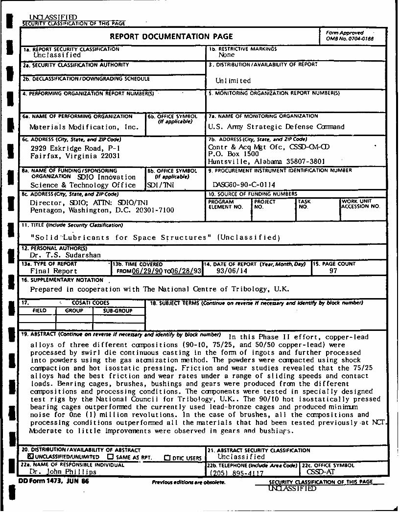
19. ABSTRACT (Continue on reverse If necesary and identify by block number) In this Phase II effort, copper-lead
alloys of three different compositions (90-10, 75/25, and 50/50 copper-lead) wereprocessed by swirl die continuous casting in the form of ingots and further processedinto powders using the gas atomization method. The powders were cmpacted using shockcampaction and hot isostatic pressing. Friction and wear studies revealed that the 75/25alloys had the best friction and wear rates under a range of sliding speeds and contactloads. Bearing cages, brushes, bushings and gears were produced from the differentcompositions and processing conditions. The cmIponents were tested in specially designedtest rigs by the National Council for Tribology, U.K.. The 90/10 hot isostatically pressedbearing cages outperformed the currently used lead-bronze cages and produced mininumnoise for One (1) million revolutions. In the case of brushes, all the compositions andprocessing conditions outperformed all the materials that had been tested previously -at KCTI bderate to little improvenents were observed in gears and bushings.
20. DISTRIBUTION/AVAILABILITY OF ABSTRACT 21. ABSTRACT SECURITY CLASSIFICATION13 UNCLASSIFIED/UNLIMITED 0 SAME AS RPT. 0 DTIC USERS Unclassified
22a. NAME OF RESPONSIBLE INDIVIDUAL 22b. TELEPHONE (Indude Area Code) 22c. OFFICE SYMBOLDr. John Phillips (205) 895-4117 CSSD-AT
DD Form 1473, JUN 86 Previous editions are obsolete. SECURITY CLASSIFICATION OF THIS PAGE3 INASSIFIED
A
"SOLID LUBRICIAiTS FOR SPACE STRUCTURES0
I Accesion ForNTIS CRA&I
PRINCIPAL INVESTIGATOR DTIC TAB
T.S. SUDARSHAN Unannounced [1Justification ................................
By ............................Distribution I
I MATERIALS MODIFICATION, INC., (MMI) Availability Codes
2929-PI Eskridge Center Dist Avail and/orSpecial
FAIRFAX, VIRGINIA 22044 i
(703) 560-1371
FINAL REPORT
(Period: 28 July 1990 - 28 Jan 1993)
PIIN DASG 60-90-C-0114DEPARTMENT OF THE ARMY
I STRATEGIC DEFENSE COMMANDHUNTSVILLE, AL 35812
FOR
STRATEGIC DEFENSE INITIATIVE ORGANIZATION
I
Acknowledgements
i The author acknowledges the ef forts of Bill McClung and Tammy
Oreskovic who assisted in the testing and to Rob Rowntree and Stevei Gill of NCT, U.K. and Dr Srivatsan of University of Akron who
provided valuable input and discussions related to testing andinterpretations of results during several aspects of this program.
I
II2
TABLE OF CONTENTS
SECTION PAGE
1.0. Introduction .............................................. 8
1.1. Characteristics of Solid Lubricants ................. 11
1.2 Processing of Composites for use as Solid
Lubricants .......................................... 13
2.0. Processing of Copper-lead Alloys ......................... 18
2.1. Continuous Casting .................................. 18
2.2. Gas Atomization Methods ............................. 19
3.0. Consolidation Methods .................................... 22
3.1. Shock Compaction .................................... 22
3.2. Hot Isostatic Pressing .............................. 27
4.0. Friction and Wear Studies ................................ 29
4.1. Friction Studies .................................... 31
4.2. Wear Rates .......................................... 35
5.0. Component Studies ........................................ 39
5.1. Component Testing ................................... 473 5.1.1. Cages ........................................ 47
5.1.2. Gears ........................................ 52
3 5.1.3. Bushings ..................................... 68
5.1.4. Brushes .................................... 80
6.0. Conclusions .............................................. 92
7.0. Further Work Recommendations ............................. 94
8.0. References ................................................ 96
3
F r LIST OF ILLUSTRATIONS
Figures Page
1 Phase Diagram for the copper-lead system ................. 14
S 2 Surface Tension of the liquids at elevated temperatures
in the copper-lead system ................................ 17
3 Typical set up for the inert gas atomization ..............204 Typical powder morphology produced in alloys ............. 20
5 Optical microscopy of spherical copper-lead powders ...... 23
6 SEM of typical spherical powders ......................... 23
7 Typical set up for "Shock Compaction" experiment ......... 24
8 Typical microstructure of "Shock Compacted"
copper-lead alloy ........................................ 26
9 Typical x-ray pattern for "Shock Compacted"
copper-lead ingot ........................................ 26
10 Interparticle bonding of 90/10 & 75/25 copper-lead
composition samples ...................................... 28
11 50/50 billet coated with lead segregation at grain
bond ...................................................... 28
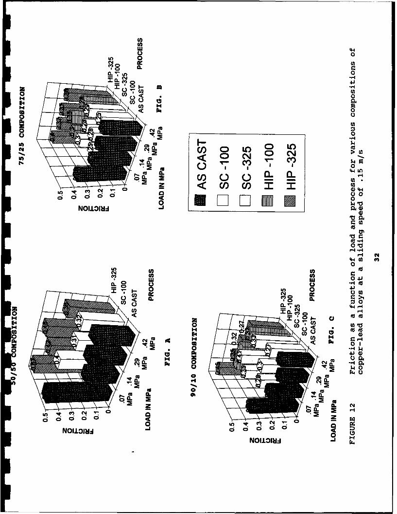
5 12 Friction as a function of load and process for various
compositions of copper-lead alloys at a sliding speed
of.15 m\s ................................................. 32
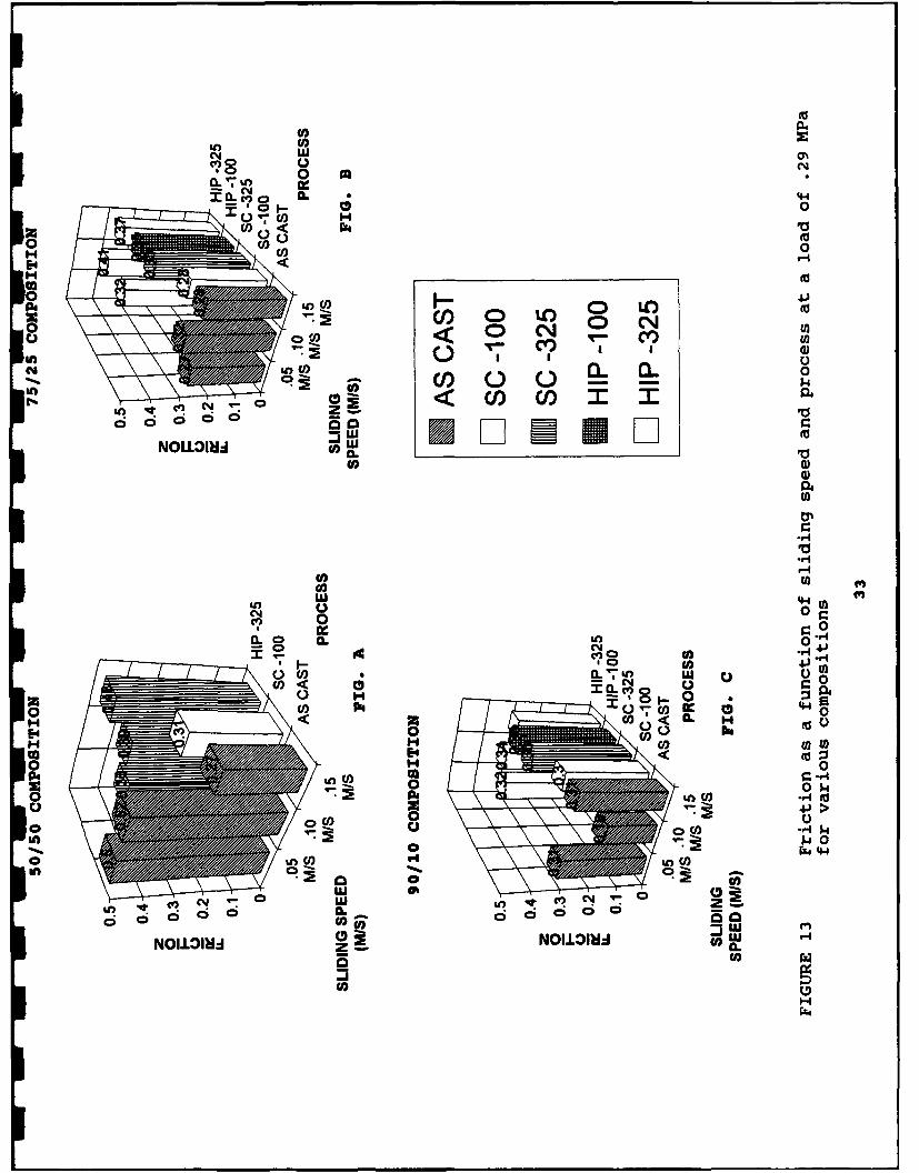
13 Friction as a function of sliding speed and process at
a load of .29 MPa for various copositons ................. 33
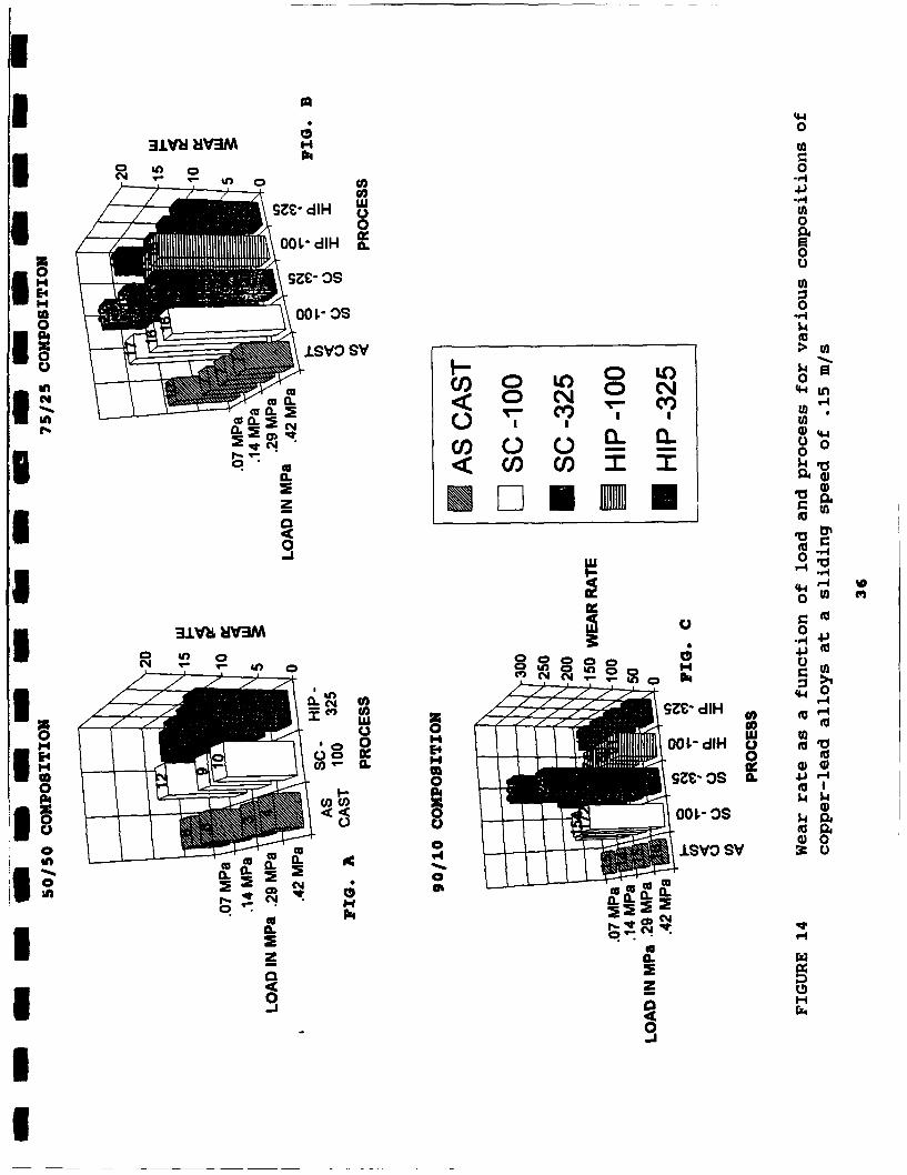
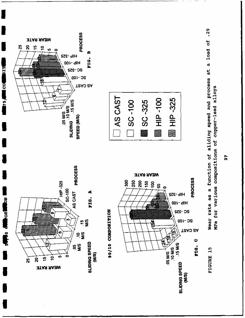
14 Wear rate as a function of load and process for various
compositions of copper-lead alloys at a sliding speed
of .15 m/s ............................................... 36
15 Wear rate as a function of sliding speed and process
for various compositions of copper-lead alloys ........... 37
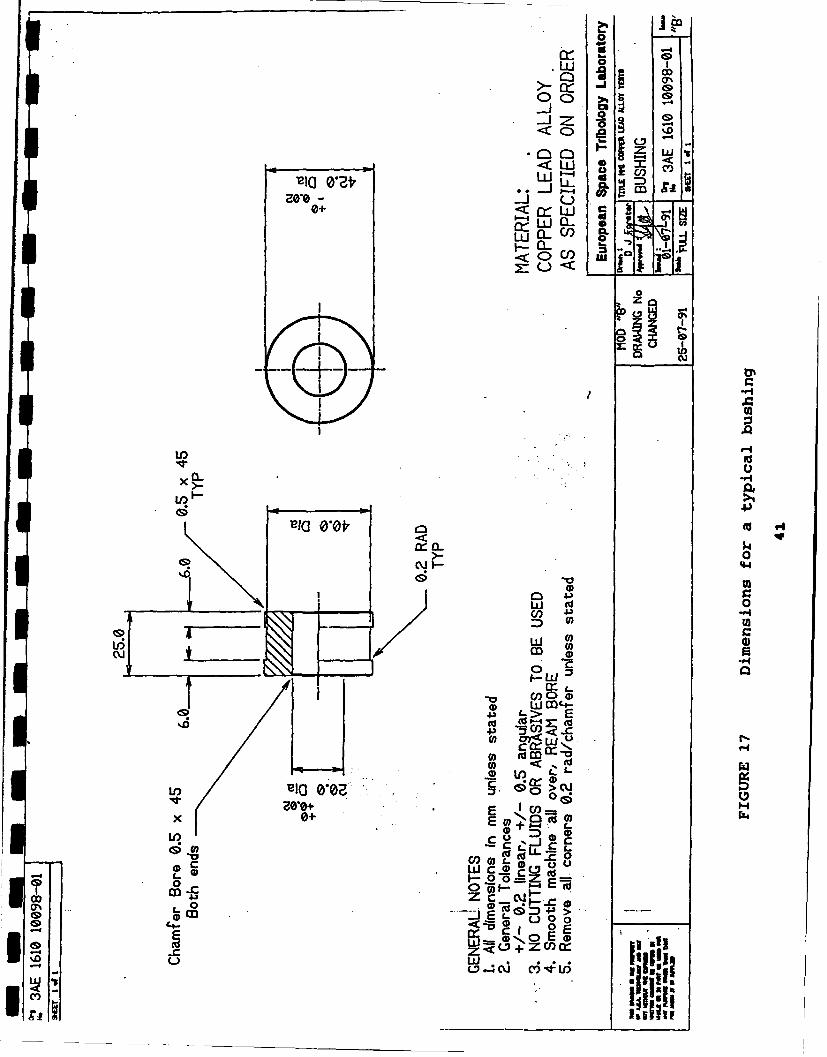
16 General view of the components for tribological testing..40
4
LIST OF ILLUSTRATIONS (cont.)
Figures Page
17 Dimensions for a typical Bushing ......................... 41
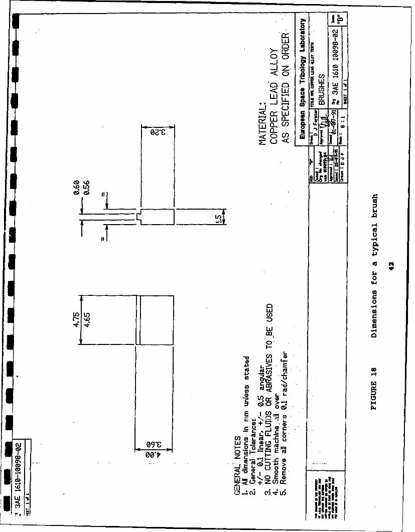
18 Dimensions for a typical Brush ........................... 42
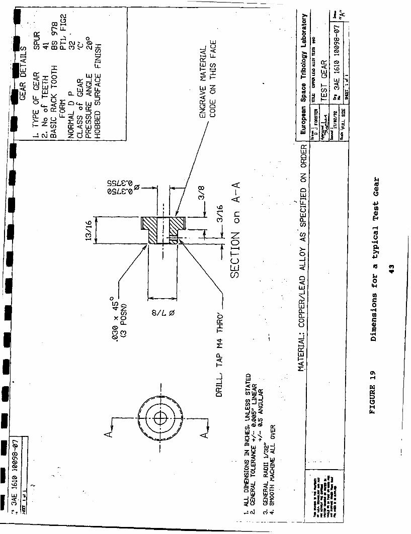
19 Dimensions for a typical Test gear ....................... 43
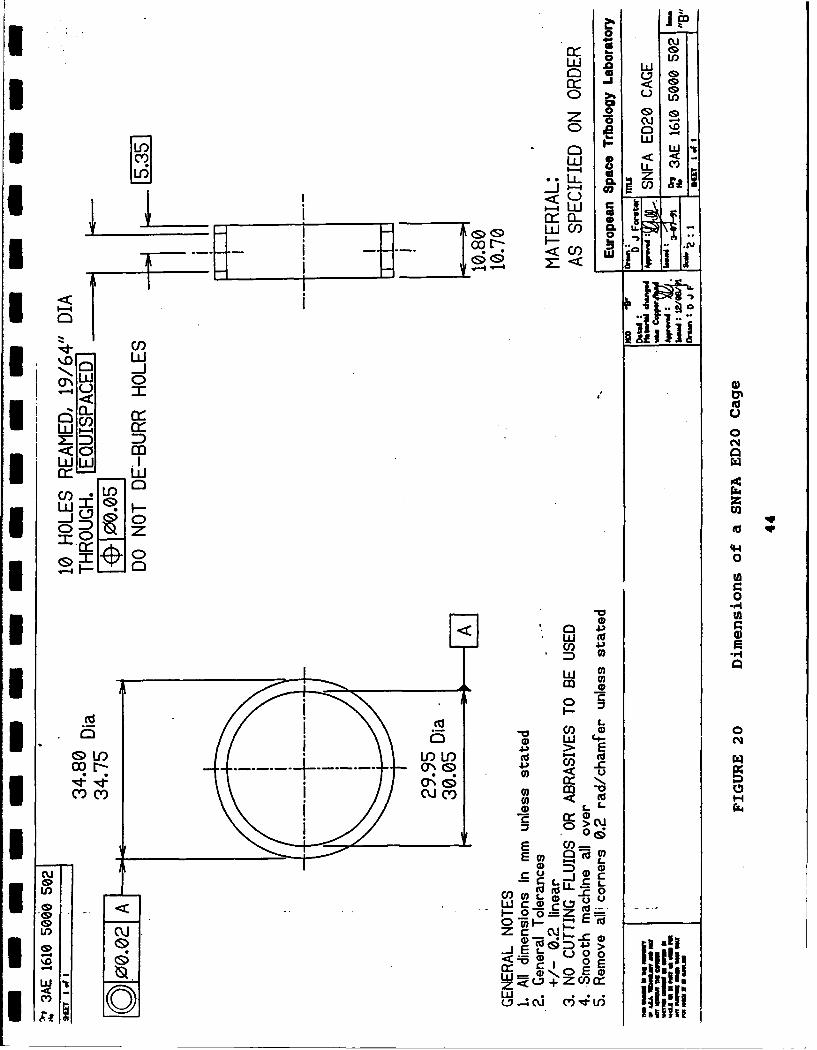
20 Dimensions of a SNFA ED20 Cage ........................... 44
21 View of the Failed "Shock Compacted" components .......... 45
22 View of the Bearing Test Facility ........................ 49
23 Cross section drawings of In-vacuo Bearing Torque
Measurement System ....................................... 50
24 Bearing Cage test results of "As Cast" material .......... 53
25 Bearing Cage test results of "HIP'ped"
-325 Mesh material ....................................... 54
26 Time versus Torque plot of 90/10 "HIP'ped" material ...... 55
27 View of the 90/10 "HIP'ped" cage and its Test Bearing
Inner Race ................................................ 56
28 View of the 50/50 "HIP'ped" cage and its Test Bearing
Inner Race ................................................ 575 29 View of the Four Square Gear Test Facility ............... 59
30 Gear test results of the "As Cast" material .............. 613 31 Gear test results of the "HIP'ped" -325 Mesh material ....6232 View of the 50/50 and 90/10 "As Cast" Gear after Testing.64
33 Close-up View of the 90/10 "As Cast" Gear after testing..65
34 Close-up View of the 90/10 "HIP'ped" Gear after testing..66
U 5
I
LIST OF ILLUSTRATIONS (cont.)
Figures Page
35 SEM Views of the 90/10 Cu/Pb "As Cast" and 90/10 Cu/Pb
"HIP'ped" Gears after Testing ............................ 67
36 View of Bushing Test Rig with Torque Measuring
Transducer and Belleville Washers ....................... 69
37 View of Bushing Test Rig showing Applied Load Sensor
in the distance .......................................... 70
38 View of 75/25 "As Cast" Bush and Mating Shaft ............ 72
39 Bushing test results of the "As Cast" material ........... 73
40 Bushing test results of the Shock Compacted
-100 + 325 material ...................................... 74
41 Bushing test results of the Shock Compacted
-325 material ...................... .......................... 75
42 Bushing test results of the "HIP'ped" -100 + 325
material ................................................. 76
43 Bushing test results of the "HIP'ped" -325 material ...... 77
44 View of 90/10 and 50/50 "As Cast" Bushings and their
Mating Shafts ................ ................................................ 79
45 Close-up View of the Bores of 50/50 As Cast and 90/10
"HIP'ped" -325 Bushings after testing .................... 81
46 View of the Slip-Ring Brush Test Facility ................ 82
47 Close-up View of Brushes contacting Silver Plated
Slip-Ring ................................................. 83
48 Slip-Ring Rig: Schematic Layout during Brush Tests ....... 85
49 Brush test results of the "As Cast" material ............. 86
50 Brush test results of the "Shock Compacted" material ..... 8751 Brush test results of the "HIP'ped" material, ............ 883 52 SEM Views of 90/10 -100 + 325 Mesh "Shock Compacted"
Brush after testing ...................................... 90
i 53 SEM Views of 50/50 -325 Mesh "HIP'ped" Brush after
testing ................................................... 91
6
LIST OF TABLESUTPble Title Page
1 Properties of Soft Metals ................................ 12
2 Average Density of Copper-Lead Alloys .................... 30
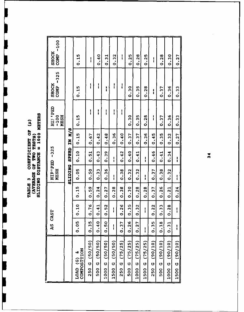
3 Coefficient of Friction for various copper-lead
processes ................................................ 34
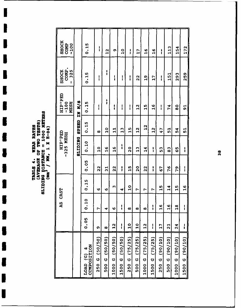
4 Wear Rates for various copper-lead processes ............. 38
5 Matrix of Test Samples ................................... 46
6 ED20 Bearing Size Parameters ............................. 48
3 7 Gear Wear Rate Measurements .............................. 63
8 Bushing Test Results ..................................... 78
I7
i
Ii
UIiUIUiU
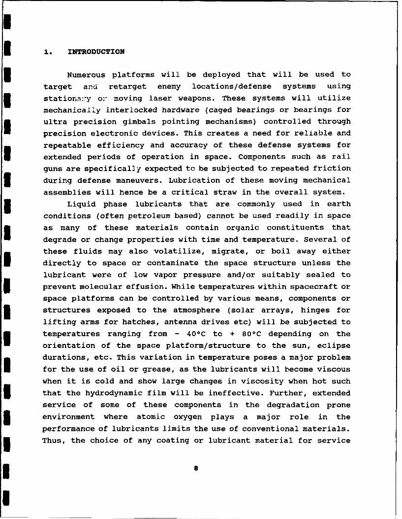
1. INTRODUCTION
*I Numerous platforms will be deployed that will be used to
target and retarget enemy locations/defense systems using
5 stationary or moving laser weapons. These systems will utilize
mechanically interlocked hardware (caged bearings or bearings for
ultra precision gimbals pointing mechanisms) controlled through
precision electronic devices. This creates a need for reliable and
repeatable efficiency and accuracy of these defense systems for
extended periods of operation in space. Components such as rail
guns are specifical]y expected to be subjected to repeated friction
3 during defense maneuvers. Lubrication of these moving mechanical
assemblies will hence be a critical straw in the overall system.
5 Liquid phase lubricants that are commonly used in earth
conditions (often petroleum based) cannot be used readily in space
as many of these materials contain organic constituents that
degrade or change properties with time and temperature. Several of
these fluids may also volatilize, migrate, or boil away either
directly to space or contaminate the space structure unless the
lubricant were of low vapor pressure and/or suitably sealed to
I prevent molecular effusion. While temperatures within spacecraft or
space platforms can be controlled by various means, components or
3 structures exposed to the atmosphere (solar arrays, hinges for
lifting arms for hatches, antenna drives etc) will be subjected to
temperatures ranging from - 40 0 C to + 80 0 C depending on the
orientation of the space platform/structure to the sun, eclipse
durations, etc. This variation in temperature poses a major problem
for the use of oil or grease, as the lubricants will become viscouswhen it is cold and show large changes in viscosity when hot such
5 that the hydrodynamic film will be ineffective. Further, extended
service of some of these components in the degradation prone
3 environment where atomic oxygen plays a major role in the
performance of lubricants limits the use of conventional materials.
3 Thus, the choice of any coating or lubricant material for service
I S
Iunder these severe conditions must be based on avoiding frequent
replacements and ensuring long term service.
Solid lubricants are materials that can provide lubrication to
two relatively moving surfaces under essentially dry conditions.
Over the years, many different types of dry lubricants have been
used and are classified as either bonded or unbonded. Most of the
technical literature on solid lubricants is relatively recent (last
50 years), however the knowledge that graphite and MoS 2 were solid
lubricants has existed for a much longer time.
In space environments where oxygen and water vapor are not
readily available to repair damaged surfaces, the performance of
I solid lubricants will be an important factor in determining the
efficiency of several operating systems. Mechanisms for use in
space and vacuum environments generally have a requirement for long
term durability with no maintenance during their life. In addition
low friction or torque levels with low frictional noise are often
desirable and furthermore over the life duration there should be
minimal wear debris production.
Solid lubrication can be achieved either by coating
tribological components with a lubricant or alternatively directly
manufacturing them from a self-lubricating material. In addition
the life of coated components can sometimes be enhanced by the
fitting of a self lubricating element which regenerates the film by
a transfer process; for example lead ion plated bearings in which
a lead bronze cage replenishes the dry lubricant on the bearing
races.
A comprehensive handbook for lubrication in space was
assembled by NASA in 1985 (1). This handbook serves as a useful
guideline for providing all the data associated with the different
types of lubricants that are currently commercially available in
the form of bonded or unbonded films. The development of strategic
defense systems that are going to experience extremely different
service conditions coupled with extended and sometimes demanding
performance has motivated the need to develop techniques for
producing solid lubricant alloys. Several methods and techniques
9
that have been developed and commercialized to produce composites
and non equilibrium alloys can now be adapted for the development
and commercialization of products for use as solid lubricants in
space and earth related applications.
Prior solid lubricant studies (2-3) have been empirical and
little attempts have been made by researchers to understand the
concept of using different types of soft metals as solid
lubricants. A number of investigations were focussed on the use of
inorganic compounds as solid lubricants (4). Some of the materials
I studied include:
* organics (soaps, fats, waxes),
1 • polymers (PTFE, polyethylene, methacrylate, polyimides),
* inorganic compounds (sulfides, chlorides, iodides,
i oxides, hydroxides), and,
0 glasses (boric oxide, silicates and phosphates).
Some of the important properties desired in a solid lubricantare:are lubricant film adhesion,
* film cohesion,
1 crystal structure,
* shear strength,
presence or absence of absorbed species,
* presence of film impurities, and,
1 the composition and finish of the substrate material.
Other materials that have been studied include double oxides,
dichalcogenides, mixed fluorides, and intercalcated layer lattice
compounds that have a hexagonal layered crystal structure. Some of
the most common compounds of this type are MoS 2 and WS2 whose
stabilities are limited by the temperature and atmosphere.
Solid lubricants offer several advantages compared to
conventional synthetic lubricants. Some of these include:
10
0 their ability to be used under high loadconditions,
a suitability for use over a wide temperature range,
o resistant to the effects of nuclear and gamma
radiation, and,
o] excellent storage stability.
The disadvantage of these solid lubricants are:
a they are generally more expensive,
a] provisions for the removal of wear debris must be
provided,
0 higher friction coefficients than with hydrodynamic
lubrication, and,
a poor elevated temperature properties.
1.1 Characteristics of Solid LubricantsSolid lubricants generally exhibit low shear strengths and
hence low friction. Crystalline lubricants undergo shear by
slipping on preferred crystallographic planes. Slipping leads to asevere plastic flow such that the solid lubricant particles adhere
to the surface as a continuous film. Further, since the particles
in the lubricant film are soft, they undergo very low abrasion.
Most solid lubricants are also thermochemically stable and hence
can be used in a wide variety of environments without problems
related to corrosion.
A limited number of soft metals can be used as solid
lubricants (see Table 1) (5). Soft metals have:
* low shear strengths,
* can be applied as continuous films over hard materials,5 good conductors of heat and electricity, and,
* stable at elevated temperatures as well as in vacuum.
I 11
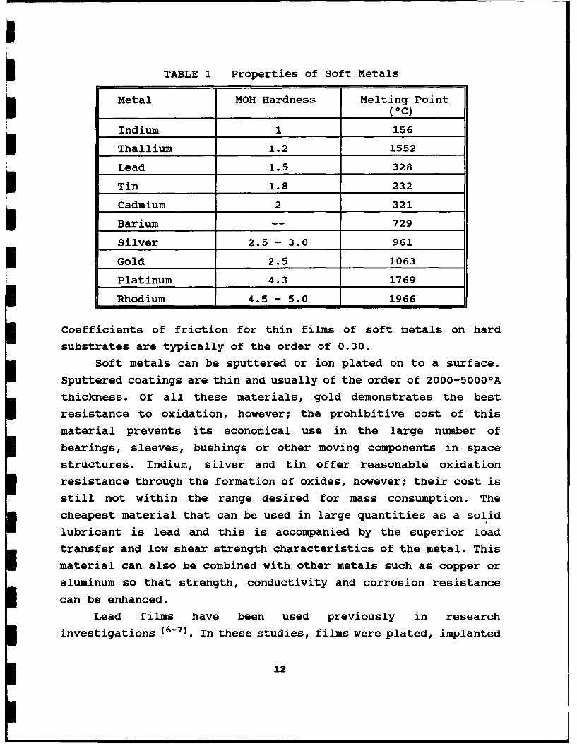
i TABLE 1 Properties of Soft Metals
Metal MOH Hardness Melting Point(OC)
Indium 1 156
Thallium 1.2 1552
Lead 1.5 328
Tin 1.8 232
Cadmium 2 321
Barium -- 729
Silver 2.5 - 3.0 961
Gold 2.5 1063
Platinum 4.3 1769
Rhodium 4.5 - 5.0 1966
Coefficients of friction for thin films of soft metals on hard
substrates are typically of the order of 0.30.
Soft metals can be sputtered or ion plated on to a surface.
Sputtered coatings are thin and usually of the order of 2000-5000 0 A
thickness. Of all these materials, gold demonstrates the best
resistance to oxidation, however; the prohibitive cost of this
material prevents its economical use in the large number of
bearings, sleeves, bushings or other moving components in space
structures. Indium, silver and tin offer reasonable oxidation
resistance through the formation of oxides, however; their cost is
still not within the range desired for mass consumption. The
cheapest material that can be used in large quantities as a solid
lubricant is lead and this is accompanied by the superior load
transfer and low shear strength characteristics of the metal. This
material can also be combined with other metals such as copper or
aluminum so that strength, conductivity and corrosion resistance
can be enhanced.
Lead films have been used previously in research
investigations (6-7). In these studies, films were plated, implanted
12
or sputtered on to the surface. One major limitation that has
hindered the use of lead is the difficulty associated with the
U plating process. Lead cannot be plated easily on many substrate
materials and the process has to be controlled carefully such that
,-- minimum formation of undesirable compounds of lead (mostly
different stoichiometries of oxides) are generated on the surface.
These compounds can be destroyed easily under loads. On the other
hand, sputtering or implantation techniques are effective but
expensive and are limited to small surfaces and to minimal
thicknesses of penetration (typically 250 microns). Use of soft
metals in several friction applications would be benefitted if a
* composite/alloy was created such that it would have alternate
islands of lubricant and a heat dissipating load bearing material.
3 A reservoir of lubrication would also be created and this could be
useful in carefully tailored combinations of alloys containing the
soft metal such that specific friction values can be attained for
a given application and also provide the benefit of extended life.
U 1.2 Processing of Composites for use as Solid Lubricants.
Copper due to its excellent thermal conductivity, affordable
* price and ability to withstand moderate mechanical strengths is a
candidate for numerous applications involving solid lubrication.
* Alloys of lead containing copper are often difficult to produce as
the two metals are immiscible. Although lead mixes with several
metals in the liquid state, immiscibility or the monotectic
reaction at the lower temperatures leads to segregation upon
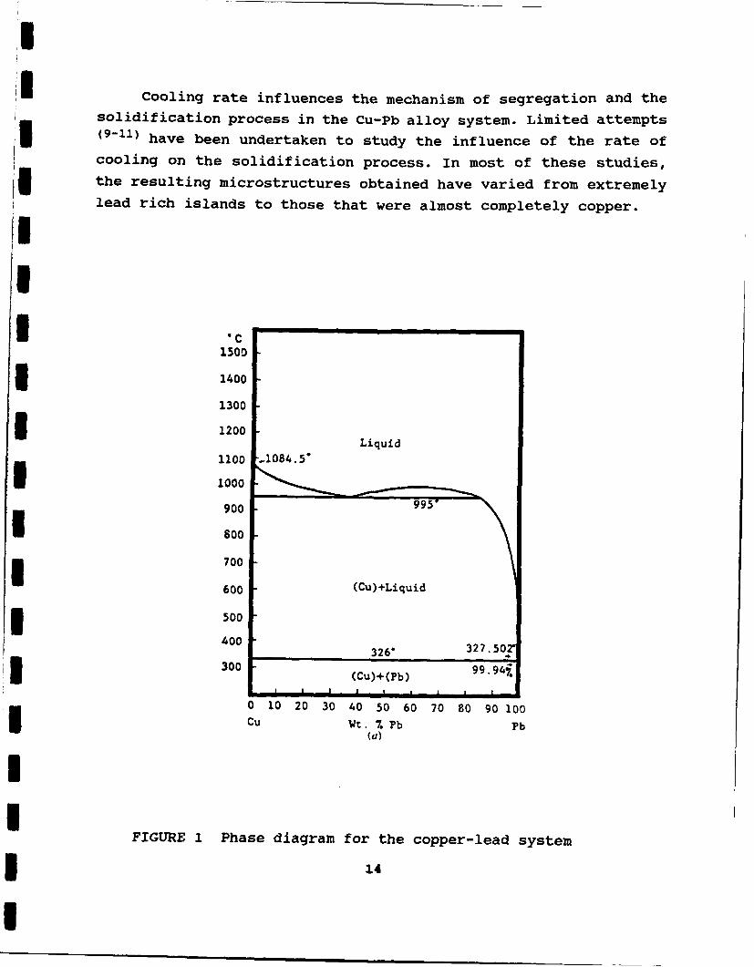
solidification. The phase diagram for the copper-lead system is
shown in Figure 1 (8). Monotectic reaction results when Liquid 1 -
Solid 1 + Liquid 2. The Liquid 2 then subsequently solidifies at a
lower temperature to Solid 1 + Solid 2. This secondary reaction
creates segregation during the transition from the liquid to the
solid state creating several phases that are rich or poor in lead.
Such phases are observed when the concentration of lead exceeds 36%
in copper-lead mixtures.
13
1
Cooling rate influences the mechanism of segregation and thesolidification process in the Cu-Pb alloy system. Limited attempts
(9-11) have been undertaken to study the influence of the rate ofcooling on the solidification process. In most of these studies,the resulting microstructures obtained have varied from extremelylead rich islands to those that were almost completely copper.I
IIC
1500
3 1400
13003 1200Liquid
1100 .1084.5'1 1000
900 9951 800
700
600 (Cu)+Liquid
500
400 326" 327.502
300999fS300 ~~(Cu)+(Pb) '9.4
S I I I I I I
0 10 20 30 40 50 60 70 80 90 100Cu Wt. Z Pb Pb
(a)
FIGURE I Phase diagram for the copper-lead system
14
In all these studies, the mechanisms associated with segregation
have been outlined. Other investigators (12-16) have attempted to
remove the immiscibility by producing lab scale quantities of these
alloys in microgravity environments using a KC-135 aircraft and
comparing these with alloys produced in gravity. Segregation of
lead to either the top or bottom of the test ingot based on the
rate of extraction of the heat continued to be a problem under
conditions of microgravity. In some cases, the addition of aluminum
appeared to show limited possibilities for homogenization of the
microstructure in the microgravity environment. For the specificcopper-lead system investigated by other researchers, microgravity
3I appeared to create little difference from the microstructures
produced in a gravity environment.
5I Investigators have also used tertiary elements to improve the
microstructure in copper-lead alloys (17). Some of these elements
3 include nickel, zinc, tin, silver and iron in percentages up to 2-
4%. The solubility of many of these elements in copper wasexcellent and this subsequently allowed the lead to wet the surface
of these alloys. This resulted in a range of microstructures that
have been well characterized and which appear to be better than the
conventional non equilibrium copper-lead alloys. Limited research
also appears to demonstrate that directional solidification of manyof these monotectic alloys were found to result in regular rod-likestructures. Similar structures have been observed in other
miscibility gap alloys (18).
Over the years, metallurgists have tried to develop process
related techniques to overcome the immiscibility of lead with
various metals. The most frequently used process for producinghigh lead mixtures is by "quick" freezing the molten metal. This
method forces the lead to solidify in the copper matrix by
entrapping islands of lead which vary in size and shape and is
dependent on the cooling process. Unfortunately, "quick" cooling
or rapid solidification techniques do not necessarily create a
solid solution and thus the immiscibility problem between copper
and lead continues to exist. Thus, the process of rapid cooling is
I5
neither reliable nor controllable and therefore not consistently
repeatable. Furthermore, the "quick" cooling process is limited in
its applicability to thin wall sections, and consequently, cannot
be useful for any large scale sections such as those produced by
* sand or centrifugal casting techniques.
Continuous casting has been used extensively by the steel
I industry and some limited facilities around the world have adapted
this method of production for non-ferrous alloys. In continuous
casting of solid rods, one type of general casting system utilizes
a stationary die which moves intermittently in a longitudinal
manner resulting thereby in the formation of the ingot. During the
3 withdrawal stroke, the casting moves fast enough so that liquid
metal enters the cooled length of the die causing intimate die-
3 metal contact. This stroke is followed by a dwell period during
which the casting is stopped or slowed so that it will exit from
the solidification zone at the proper temperature.
However, in many cases, non equilibrium microstructures are
generated because of the gross directional solidification that
results when the material transitions from the liquid to the solid
state. Such gross directional solidification results when the
crystals or grains grow in a direction opposite to the direction of
heat flow. Mechanical working of such non-uniform microstructures
results in cracks and imperfections that renders the product unfit
for any engineering application. In cases where the liquid metal is
3 extremely hot or the casting speed too slow, the grain structure
takes on a coarse configuration that cannot be altered easily
during subsequent cold working operations.
Thus continuous cast materials of non ferrous alloys such as
copper or aluminum have resulted in gradients across the cross
I section and the length of the material. While such inhomogeneity is
tolerated in some applications, these alloys are unfit for use in
3 tribological applications where uniformity in microstructure is
desired.
I Recently, a process that utilizes a special die was designed
for incorporation in the continuous cast system. The die made of
16
Recently, a process that utilizes a special die was designedfor incorporation in the continuous cast system. The die made of
graphite, consists of a plurality of openings or holes located inthe die and positioned (unlined) relative to each other in such amanner that a cyclonic or swirling motion is produced in the liquidalloy as it flows into the die. This stirring of the liquid alloyclose to the near freezing zone facilitates the fragmentation ofthe liquid droplets and thus the homogenous distribution of the
phases in the solidifying die.
In the case of producing non equilibrium copper-lead alloysand other miscibility gap systems, a new technique that usesproprietary organic and inorganic salts during melting,facilitates the reduction in surface tension between the two metalsat elevated temperatures and also induces a vigorous stirring
action creating tiny droplets that act as nuclei and form anemulsion instead of the normal mixtures. This facilitates non
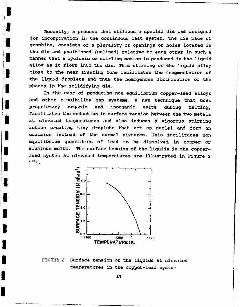
equilibrium quantities of lead to be dissolved in copper oraluminum melts. The surface tension of the liquids in the copper-lead system at elevated temperatures are illustrated in Figure 2(14). f; '
4 .I 4.0
53.0
P 0.0U .o
1200 1250 1300TEMPERATURE (KW
FIGURE 2 Surface tension of the liquids at elevatedtemperatures in the copper-lead system
17
I
* Lowering of the surface tension improves miscibility and in
combination with the swirl die (facilitates the breaking up of the
melt stream prior to solidification) fine grained materials can be
produced. Thus, this technique ensures that lead stays homogenous
with the copper and can also be continuously cast into bars, rods
or tubes up to 9 inches in diameter. Alloys containing up to 60%
lead can be produced using this technique under carefully
controlled melting conditions.
I 2. PROCESSING OF COPPER-LEAD ALLOYS
2.1 Continuous Casting Methods
Copper-lead alloys of nominal compositions Cu 90-10 Pb, Cu 75-
25 Pb, Cu 50-50 Pb (weight percent) were melted in an induction
furnace with a capacity of 2000 lbs. The charge sequence for
melting consisted of first adding the copper and waiting for the
copper to melt completely and reach a temperature of 1300 0 C prior
to addition of the lead. Due to the large degree of superheat, the
lead melts immediately and reduces the temperature of the melt. The
temperature was raised again to 1300 0 C and deoxidant under thetrade name of "Phos Copper" marketed by Foseco, Cleveland, Ohio was
* added to remove the oxides that collect on top of the melt in the
form of a slag. Deslagging was achieved by skimming the slag from
the surface of the melt. Proprietary additives were then added.
The preparation of the additive consisted of mixing known
quantities of sodium carbonate, cupric phosphate, silver sulfide in
"a beaker and subsequently wrapping them in lead foil in the form of
"a pouch. Lead foil serves as a excellent carrier for the additives
as it sinks to the bottom of the melt during the dissolutionprocess and therefore facilitates intimate mixing with the molten
melt. The proprietary additives were always added just prior to
casting.
3 Continuous casting was achieved by using a patented swirl die
designed using graphite. The die has angular holes positioned
3 equidistant along the periphery. This causes the molten metal
stream to pass through the holes in the die and swirl as it enters
I
I
I the continuous caster. A combination of the aggressive reactions
induced by the additives coupled with the vigorous induced mixing
S by the swirl die results in a very close control over the
microstructure. The draw rate of the motor was adjusted to ensure
that only fine grained materials were produced.
All alloys were produced in the form of 3 inch diameter ingots
and samples were machined from these ingots for all studies in this
research effort. A selected portion of the ingot material was
converted to powder using a inert gas atomization process to study
the effects of powder metallurgy consolidation methods and
properties on component behavior.
2.2 Gas Atomization Methods
I The conversion of copper-lead to spherical powder is achieved
by a inert gas atomization process. In this process, the ingot
produced using the swirl die continuous casting method is first
melted in an induction furnace at around 912 - 10830 C and held for
five to ten minutes for complete homogenization of composition. A
blanket of sodium carbonate is placed over the melt surface toensure that there is no oxygen pick up from the environment and to
also ensure that the lead and the copper stay mixed in solution at
the elevated temperature. A nozzle at the bottom of the holding pot
I allows the flow of the molten metal stream into the atomization
chamber for conversion to powder. The nozzle can be plugged or
unplugged with a stainless steel stopper rod that has a pointed V
shaped configuration. A typical schematic of the gas atomization
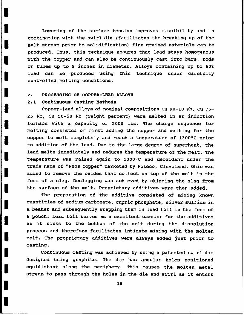
process is shown in Figure 3.
A low porosity (less than 5 %) zirconia nozzle available from
Zircoa (Union Carbide subsidiary) was used in all the powder
conversion experiments. The crucible containing the hot metal
(copper-lead) is placed over the atomization chamber and the
3 stopper rod is removed. The metal flows in a cylindrical stream and
is met by a perpendicularly injected gas flow of nitrogen through
a annular ring in the atomization chamber. The pressure of the gas
determines the ability to break the molten metal stream into
*19
Iinduction-
gas..mette r.soure'
I""I
fine :o.*.
powder..
IFIGURE 3 Typical set up for Inert Gas Atomization
I~spherical tO
I j rotundeW .
14cikic sponge orLF &Porus
A4cular.
I
vo5 iregla2r
flake c ~ r u
týýpolygonai
"$ndrfti
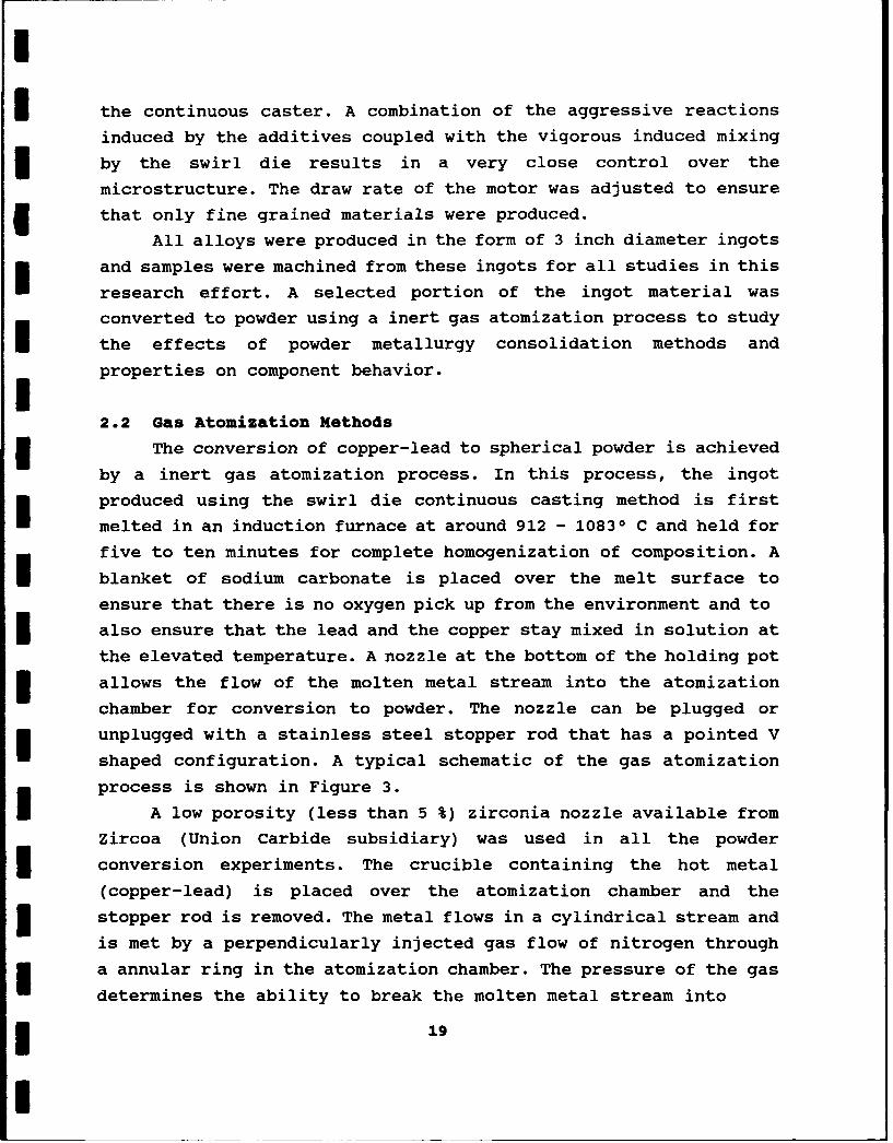
FIGURE 4 Typical powder morphology produced in alloys
* 20
I droplets. The process of free fall solidifies the droplets and
collects at the bottom of the atomization chamber as a solidified
3 powder. A range of powder sizes is produced in any inert gas
atomization process and careful control over pressure can maximize
the creation of a particular powder size and shape. Lower pressures
and use of gases such as helium, argon, hydrogen or oxygen can
result in the formation of powders of different shapes other than
spherical. Typical powder shapes are illustrated in Figure 4.
If coarse spherical powders are desired (+325 mesh to -100
mesh) low pressures (200-250 psi) are used, if very fine spherical
powders are desired (-325 mesh), higher pressures are desired (250-
400 psi). Since most powder metallurgy products use coarse powder
to achieve uniform sintering characteristics, we chose the 200-250
psi range for the pressure of the inert nitrogen. This ensured that
we had uniformly round powders independent of composition.
In any inert gas atomization system, a certain proportion of
the powders also end up in the very fine range and are collected in
a cyclone separator that is located in the gas atomization chamber.
One of the major problems noticed during production was the
corrosive nature of the hot metal. As the lead content increased
the nozzles were badly eroded. This can be attributed to the
infiltration of the pores in the nozzle by the hot metal and the
* chemical attack that occurs along the grain boundaries between the
lead rich metal and zirconia.
After atomization, the powder that is collected in the cyclone
separator and the container at the bottom of the chamber were
subjected to sieve analysis. This ensures a clean mixing of the
different powder sizes for further use in powder metallurgy
applications. The powder was classified into three sizes by using
mechanical sieve shakers with three different sieves. The sizes
were -325 mesh, +325 to -100 mesh and +100 mesh. The different
3 sizes were then packed in plastic lined drums and carefully sealed
with silica gel to ensure that no moisture contaminated the raw
material powders. Optical and scanning electron microscopy was
performed on the typical spherical powders (different sizes) and
!21
are displayed in Figures 5-6. Homogenous spherical powders were
observed in all the three different compositions and tae two
different sizes (-325 mesh and +325 to -100 mesh).
3. CONSOLIDATION METHODS
3.. Shock Compaction
Shock compaction is an extremely rapid near net shape
technique for consolidation of powders. It has been used in the
past to consolidate compositions in shapes or forms that are very
difficult by any of the conventiona± heat assisted consolidation
techniques. When a shock wave is applied and is traveling at a high
3 velocity, the heat generated between the packed powder particles
creates interparticle friction and hence localized fusion. If
I proper conditions are applied the materials can form consolidated
products that are near theoretical density.
In the case of atomized copper-lead powders that have fine
distributions of lead dispersed in the matrix, consolidation using
sustained exposure to thermal sources will result in diffusion of
the lead to the exterior surface and possible agglomeration of the
lead. This is not desired if both self lubricating and mechanical
properties are desired. Hence techniques that can minimize any
diffusion of lead and maintain the fine distribution in the copper
3 matrix are preferred.
In "Shock Compaction" of copper-lead powders, the lead
distribution can be retained in the fine form such that extremely
good self lubrication will be feasible without a compromise in the
mechanical properties thereby ensuring a long life for the
bearings, cages or bushings. A typical set up for a "Shock
Compaction" experiment is shown in Figure 7.
5 In the shock wave compaction set up, powders of the three
different compositions were packed into a hollow steel cylinder of
I 42 inch length and 3.5 inch diameter. This cylinder is then
enclosed in a larger diameter (4.5 inch) pipe of the same length.
Each of the three compositions had two sizes of powders, the +325
mesh to -100 mesh (coarse powders) and -325 mesh, (fine powders).
322
i
FIGURE 5 Optical microscopy of spherical copper-lead
powders (Magnification 750X)
I
IIli
FIGURE 6 SEM of typical spherical powders
(Magnification 200X)
23
DOUBLE TUBEI IMPLOSION GEOMETRY
.. ..I. ..*. ........................ ... ... ... ... ... .5j ...... ..........ORON
ANFO
f-4.5* -
3I-- PVC PIPE
3~O PLUG
144 CNAE
30
II
3 FIGURE 7 Typical set up for a "Shock compaction"
experiment
* 24
The powders were packed by tapping and gentle shaking of the steel
cylinder and the density of packing was calculated to be 59-62%.
This is the normal packing density for the hollow cylinder
configuration.
The cylinders were placed in a 12" inch diameter plastic tube
and Ammonium Nitrate mixed with diesel oil and termed commercially
as ANFO was packed in the space between the steel and the plastic
cylinders. A flat wooden plate was placed on top of the pipe and a
detonator fuse was attached to the system. The other end of the
fuse was attached to the power discharge system.
The power discharge system consists of a charge-discharge
capacitor. A short circuit was created by discharging the power
into the fuse creating a spark that ignites the ANFO. The shock
3 wave that is created due to this process moves from top to bottom
and from the outside to inside of the cylinder at about 1.5 km/sec.
This creates tremendous interparticle friction (plastic
deformation) between the powder particles and thereby generates
incipient fusion of the particles resulting in the formation of an
I ingot.
Six ingots were produced (three compositions of two particle
3 sizes each). During machining of the outer steel sleeve, the -325
mesh ingot of 50/50 copper-lead composition fractured at several
3 locations probably due -to the high internal stresses developed
during shock compaction. Only small selected regions were free of
cracks and for all practical purposes it was difficult to salvage
sections that would be large enough to produce components. Hence
50/50 (-325 mesh) copper-lead "Shock Compacted" ingots were not
available for friction and wear or component testing. The typical
microstructure of a "Shock Compacted" ingot is shown in Figure 8.
The interesting feature observed was the extra fine structure
within the grains of the ingot. The dark areas represent lead and
3 the white areas represent copper. No other known metallurgical
process can create such fine grain sizes in such large ingots other
than shock-wave compaction.
25
le
FIGURE 8 Typical microstructure of a "Shock Compacted"
copper-lead alloy (Magnification 400X)
4000
1 Cu
3200 2 Pb
3 PbO
2400 4 Unknown
.2 1600
S 3 ý2 4 2
0
10 20 30 40 50 60 70 80 90 100
Two Theta Angle
FIGURE 9 Typical x-ray pattern for "Shock Compacted" copper-
lead ingot
26
- X-ray diffraction studies on the "Shock Compacted" samples showedpresence of both copper and lead and a small amount of lead oxide.
A typical x-ray pattern is shown in Figure 9.
Friction and wear studies were performed using a ball on flatmachine and component life testing was performed on test rigsspecially designed for space environment simulation by the NationalCouncil for Tribology (NCT) U.K. Tests were run on the different
ingots produced using the "Shock Compaction" process.
3.2 Hot Isostatic Pressing (HIP'ping)Hot I-ostatic Pressing ("HIP'ping") was used to fabricate bars
of the various gas atomized powder materials. "Hip'ping" wasperformed at 750 0C for one hour under an argon gas pressure of 103MPa. All "HIP'ping" was performed by HIP Ltd in Derbyshire, U.K..Mild steel capsules (65 mm diameter x 95 mm long) were used toproduce the "HIP'ped" samples. The nominal size of the bar producedafter "HIP'ping" was 42 mm diameter x 75 mm long. A mild steel foilwasher and smaller diameter foil plate were placed on top of the
powder to be compacted and a mild steel lid was welded onto thesteel capsule and an evacuation tube attached. The presence of the
foil sections was to prevent the loss of the fine powder duringevacuation. The capsules were evacuated using a double stage rotary3 pump to a pressure less than 1 x 10⁻² mbar. Sealing of the capsuleswas achieved by hot crimping the evacuation tubes while under5 vacuum. Each capsule was individually "HIP'ped" to achieveddensification. The HIP'ping studies revealed the followingobservations:
a) The 90-10 and the 75-25 developed good interparticle bondingand very little lead segregation except a small layer on theoutermost surface. This suggests that the gas atomized powdershad indeed locked the lead inside the copper matrix therebypreventing leaching of the lead and the loss of itslubricating ability. (See Figure 10.)
27
I . . . . . . . " " • - • .
FIGURE 10 Interparticle bonding of 90/10 &75/25 copper-lead
composition samples (Magnification 200X)
ItII
'44k
FIGURE 10 50/50 billet coated with lead segregation at.grain
bond (Magnification 50X)
28
b) The 50-50 billet was coated with a film of lead and some lead
segregation at the grain boundaries was observed. (See Figure
11.) There was also a gradient in the density across the
diameter of the bar. This suggests that the "HIP'ping"
parameters used were approaching the melting temperatures of
lead and hence some amount of fluidity of the lead resulted in
the coating of the particles.
4.0 FRICTION AND WEAR STUDIES
Flat disks of 2" diameter and 0.25" thickness were machined
from the ingots that were "As Cast" (AC), "Shock Compacted (SC), or
"HIP'ped" (HIP) and used in all the friction and wear studies. The
tests were performed using a ball on flat disk machine. The ball
was 5/16" diameter 52100 hardened to HRc 50. Although the
temperature and humidity were not continuously controlled, the
tests were run in conditions between 65 0 F - 73 0 F and relative
humidity of 27 - 50%. Each set of copper-lead disk and steel ball
were thoroughly cleaned in an ultrasonic cleaner using methanol for
approximately 2 minutes. The weights of the ball and copper-lead
disk were recorded before and after each test. After the friction
test was completed the disk samples were again cleaned in methanol
and the difference in weight was used for calculation of volume
loss. Since there was no substantial weight gain for the ball, only
the weight loss for the disk was taken into account for calculating
the volume loss for each sample.
The friction tests were performed in a computer controlled
system, by allowing the stationary ball to rub against the plane
surface of the rotating sample. Three different sliding speeds
(0.05 m/s, 0.10 m/s and 0.15 m/s) and normal pressures ranging from5.07 MPa to .42 MPa (which correspond to 250 grams to 1500 grams
axial load) were applied to the surface of the sample. All samples
were tested for a total sliding distance of 1000 meters.
The force resulting from the friction between the ball and
disk was measured by a transducer and recorded by a computer. A Q
Basic computer program designed for this machine was used to
29
acquire the data at regular intervals so that the calculated values
could be displayed on the computer screen in terms of the
coefficient of friction versus time (sec). The coefficient of
friction is defined as:
NI Coefficient of friction (p) = Force / Applied load NThe data derived from the test related to the coefficient of
friction was averaged and plotted as a data point by the computer
every 5 - 20 seconds depending on the sliding speed.
Volume loss for each disk was calculated by measuring the mass
loss.
I volume loss, mm 3 = Mass Loss, (g) X 1000/ Density, g/cm3 IN
Since each copper-lead composition was based on weight percent, the
density was an average of the densities of copper (8.93 g/cm3 ) and
lead (11.38 g/cm3 ) in the appropriate ratios. (See Table 2)
TABLE 2 Average Density of Copper-Lead Alloys
COMPOSITION DENSITY g/cm3
50/50 9.13
75/25 9.44
90/10 10.01
By calculating the volume loss, the specific wear rate was
calculated for each material and sample tested.
Specific Wear Rate = Volume loss, mm3 /
Normal force (N) X distance (M)
30
The Normal force is defined as:
j Normal force = Gravity (M/s 2 ) X Load (kg)
4.1 Friction StudiesThe coefficient of friction for the varying processes and
specific compositions tested in this program are shown as afunction of load and composition (Figures 12A - 12C) and as a
function of sliding speed (Figures 13A - 13C). A complete listing
of all the data collected in this program is shown in Table 3. The
principal observations are:
* An increase in applied load resulted in a decrease in friction
independent of sliding speed, composition, or manufacturing/consolidation processes.
• Increase in the lead content generally resulted in an increase
in friction for all the processing conditions evaluated inthis study. This could be attributed to the rapid formation ofa film and its subsequent oxidation to PbO that is brittle andhence promotes formation of debris.3 Increase in sliding speed resulted in increase in friction forall the "HIP'ped" compositions. This occured probably due tothe easy break up of the particles and their subsequent
oxidation. In contrast the "As Cast" materials demonstrated
minimal changes in the friction values except in the case of
50/50 where an increase was observed at lower sliding speeds.This could be attributed to the distribution of lead withinthe matrix and the ability of the "As Cast" materials torapidly form a transfer film.5 Changes in particle size did not affect the friction valuesfor all loads, compositions, or sliding speeds.3 For all the different conditions tested in this program the"HIP'ped" compositions had the most consistent values. (See
Table 3.)
31
CO)
w (44(L 0
W, 0T .
CL 0C.4 rq
C0 U,)
N 0co o0 6 < 0
0 U.
0000 00
"N.%. WI .2 0O C lC
CL 0
0 0 00
c~0
0~00Ng
00
0 *F-4 -r
00
CL a toC~
0OL WO 0r.V
It)z
T 0 10 0
F: 0
o L)
0 0 0%J
00
0 N C)
ianaI
0i (aCi 0
CCJ
LO 0 wCM 0
00
0 CM 4
o to00 CO) wf0
0 0 ,C) c4
E-4rz 4-4 COto E-4 <
0 0.
0 rz 4
V- $4H
0OH N L D L D 0 r0
LnN
LA I I I O) L ON O (
Q- I4 (n o~ Ln co r %S0 (n en N m en *
C) O 0 000 000 - D
0z Ii AM e I m m mZ * 0.4 . . . . .
LA 01 LA C, I , 1 D 0 0
SLA Nl N w w~ 0 % I- w LA LA N N-
No
I -I * * * *
0 0 0 0 0 00
pa aA 04 Mr '0 C NO N m m
0 0 0 1 0 00 I 0 00 I
o4 o oo 0 000 0 0 0 00 0
0 ~ N %o LAN N Cr1 m O
E-i I *ý *ý *O 0 00(D0 0 0 00C)0
LA LA) 0 0 tN %0 Nl LA CO IimO 0 C1 LA I (n1 N N1 Mr V- CV)
0 000O000 1 000;
0 00o0 LA LA LA LA 0000oLn Ln LA LA Nq Nq Nq N~ H- H- H H
'8 00 0 00 LA LA LA 0 00 0
OH
0
4 LA 0 00 LA 000 LA 00000 N LA LAm N LA LA0 N LA LA. ) r4 H- w-4 H- H H
4.2 Wear Rates
In addition to the friction values, wear rates were calculated
for all the tests conducted in this program using the procedure
described earlier and are presented in Table 4. The wear data from
Table 4 is graphically illustrated as a function of load and
process in Figures 14A - 14C and as a function of sliding speed and
process in Figures 15A - 15C. The general observations include:
* As lead content decreased below 25% there was a significant
increase in the wear rate for all the materials and process
conditions tested in this program. This suggests that
insufficient material was available to form the transfer film.
* Increase in applied load resulted in an increase in the wear
rate except in the 50/50 and 75/25 "Shock Compacted" material
where there was a tendency for a reduction in the wear rates.
This could be attributed to the speed of formation of the
transfer film and its subsequent oxidation except in the case
of the "shock compacted" samples where the fine distribution
of lead may have lead to a more homogeneous formation of the
transfer film.
0 Increasing the sliding speed, was accompanied by a decrease in
wear rate for all compositions and processing conditions.
* The "As Cast" material in all three cases of load,
composition, and sliding speed had the lowest wear rate
values.
* The "Shock Compacted" material (both meshes -100 + 325 and -
325) showed extremely high wear rates especially in the 90/10
composition. Such results may be due to the high stresses
present in the material after compaction as no post heat
treatment was applied to reduce the stresses.
35
3 031vs 4.4
040CM VI~~
SZE- d1H .
0 019
OW d1H I0
H 0
< Cl) LOI) N 44 2hnM cC V0a. 2 < CfawSEC4
CL __ _ _ ___ m 4w*1:CU) C) 0 0I<I t
CLVVI 04I
001p.4
o (A'ai Hvm 05CC
440
UUtIO0 HL
u 4400
SM- dIH 0
- ------- gS - as
0In01,O U)C) OCO))
&(1c) 0 0 04 -
CCL
4l) 0
~.,I0~ ~~~~~~ __ _ _ _ _ _ _ __ _ _ _ _.-* " 0
IflU
0-~ coCD)
0D SZ-II'40
m ~4)0a>
00
LU A: inI
&I 00IoI
0 a r I I~ e~0IN % ~ -n N
=/U 0 C; 1-C4 () I t1 r ,-4D w- I fr4 L4 r,
in 04 1- rM: r N- H I I I T O1 N i i o 4I
II oIt I I I m% %0 14 v 0- C -4
I q - -I(
0 in
Ln I 0 % w 1 0 m w I n r) in Iit P0 C14 H N N -4 '-I I v-4 % 1I
H~~~~~ ~ ~ '0I H0 CC O 0 C4 1 t o CYN4 Me c I NO NO N I w- t%- r-I I
I 00,0
E- -- Z -
H in 0w in N i f n 0 %If1-4 'D %Dt- v1-4 II - - - =- =- - = -= -= * CA
I6
S.0 COMPONENT STUDIES (National Council for Tribology U.K.)
Four different types of tribological components that are used
in space systems were manufactured using the copper-lead alloys
produced in this program for testing in special test rigs available
at the National Council for Tribology, UK (NCT). The components
were:
* Ball bearing cages,
* Gears,
* Bushings, and,
I * Electrical motor brushes.
The manufacture of all these components was undertaken by
Premax Engineering Ltd, of Birmingham, United Kingdom who were
accredited to follow the quality standards prescribed by British
Standards, BS 5750-broadly equivalent to International Standards
Organization, ISO 9001.
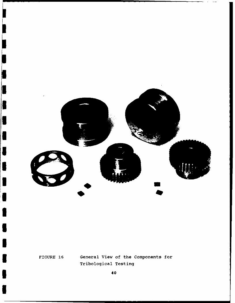
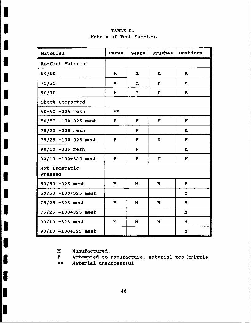
Figure 16 is a general view of the tribological components
tested in this program. The engineering drawings for these
components are provided in Figures 17-20. Table 5 provides a
detailed summary of the various components manufactured and tested
in this program.
One of the inherent limitations of the shock compaction
process is reduced ductility (brittle). Hence, no cages or gears
which had intricate geometries could be manufactured from the
"Shock Compacted" material. The benefits of extremely fine
microstructures and thereby the lead distribution derived by the
shock compaction process can be optimized only if extensive process
parameter studies related to improving the ductility are
undertaken. This can facilitate easier manufacturing and the
microstructural improvement "Shock Compacted" cages could result in
greater benefits than the currently used standard lead bronze.
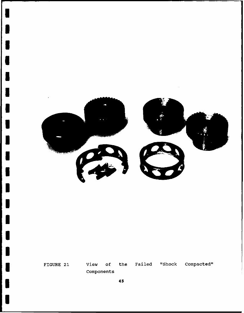
Figure 21 is a typical example of some of the cracked
specimens. The cracked gears also had missing teeth, and in one
case the gear blank itself was cracked. The cages manufactured
using the "Shock Compacted" material were just too brittle to
handle, and some even failed after arrival at NCT during
39
II
FIUE1 eea iw fteCmoet oTrblgcaIetn
*4
I
b..a4-4
01%
00.-iz
< w200a -TI Li-J (.p
0+ <CC LI
C I - ,
<CI) U_
0
cu
x f-I
">- jai
ixa
0 - 0
IJ 0
m 0
0 0
I~wCCO
0) W CD4-IS! ~4Jt L> E
M) uM -0
0- 0I LL
?0*0+ Ecn-X 0+ 0 -R 0U
.9 Cu
-~W C.2 Co EOD w c c
CP% 0 CD -o5 -.
u0EII
w !zu+ z CODclci-c C I
__L_ ___ _________ bwi'N~L ____ ______ _6___
0
ED 0
0 0
-iz
< w ou C/ij 1-4
IJ (-3
w CL
U <'
11
G4 gj
4.)
14 £
0
_______ U
0
U) Cl)
LLJ
(P L>
Lo W60Il)
o 6
00
.2 -
zo 0 W-- E
00 7r- LL
ccr-
Cl) <<LLJC,)
LL LJ <ci<
LU < QJL)
*< = jx 0 **r
U Dx0, u L U) 0
>-ZooSSV0 Co) 0K<L
OSLC0
0 $4
0V <C'1-4
C. ) -J
Cl) z co
0 . 0
W 0
0/L
x 0 0 ..0.. cr. 0
1-4cr
OL. w<CI
0
W
. c co.W
zw
-l c cr
mILCu
z .2 4s0 CU
I., ' -I ý 0
_j - 2)<- U
cr 0)(S> 0
I~W w
oCl) .10
< 00
a: 4.'40
(> 0 0
010
m -
0O LOLL
00~~~~ -- - -- c*,()cfEý Gl
C o 0\ (Y) M
<C~o~,L L.C
cu0 !I)i;I
UIUIII
IIII
IFIGURE 21 View of the Failed "Shock Compacted"
I Components
I
I TABLE 5.Matrix of Test Samples.
Material JCages Gears Brushes Bushings
I As-Cast Material
3 50/50 M M M M
75/25 M M M M
90/10 M M M M
Shock Compacted
3 50-50 -325 mesh **
50/50 -100+325 mesh F F M M
75/25 -325 mesh F M
3 75/25 -100+325 mesh F F M M
90/10 -325 mesh F M
3 90/10 -100+325 mesh F F M M
Hot Isostatic3 Pressed
50/50 -325 mesh M M M M
3 50/50 -100+325 mesh M
75/25 -325 mesh M M M M
I 75/25 -100+325 mesh M
90/10 -325 mesh M M M M
90/10 -100+325 mesh M
M Manufactured.F Attempted to manufacture, material too brittle** Material unsuccessful
46
I
I preparations for testing. This probably occurred due to the
internal stresses developed during consolidation (shock compaction)
that were relieved during manufacturing operations.
5.1 Component Testing.
Standard in vacuum test facilities available at NCT were used
to test the components by examining their torque performance. Such
information provides an indication of the overall endurance of the
component. The extensive tribological testing performed by NCT in
the past on a wide variety of materials was the basis for the
selection of the test conditions in this program. This also
facilitated direct correlation with existing data. All testing was
performed at ambient temperature (20 0 C +/- 20C controlled in the
3 laboratory) using calibrated instruments and power supplies. For
the cages, bushings and gears the data was acquired on a chart
recorder, in line with previous testing at NCT. The brush test
measurements were taken using a Solartron Type 7066 computing
digital voltmeter for the 100mv range and the time period of these
measurements, had an accuracy of ± 0.001%.
I 5.1.1. Cages.
The National Centre of Tribology developed the use of ion
* plated lead films as a lubricant with a high load carrying capacity
for spacecraft components as early as 1972. These films have a
limited ability to operate under atmospheric conditions, currently
a distinct advantage over some of the more exotic MoS 2 coatings.
When applied to rolling element bearings, a lead bronze cage is
additionally employed. One of the functions of this cage is to
transfer lead bronze via the balls to the race, thus replenishing
the lead film. However, with the increasing life and speed
requirements of the space industry limitations are now being set by
3 the cage behavior; in particular the formation of wear particles.
I
I
I
I Early research (19) showed that a continuously cast lead
bronze, of approximately 10% lead, was the optimum choice based ona bearing duty of two million revolutions. This research alsoexamined some of the factors which affected the transfer rate and
* the subsequent torque noise registered by bearings fitted with lead
bronze cages.Since this early research (19 - 20), limitations have started
to appear in the performance of these lead bronze cage materials.
The performance of the bearings has always been susceptible to wear
of the cage and subsequently induced noise. In situations, whereextended life was required (> 108 revolutions) cage wear wassignificant and where variations in speed occurred, cage inertia
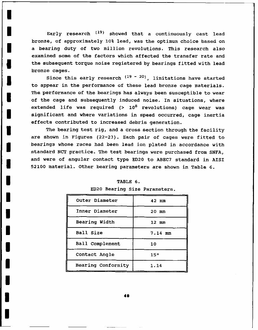
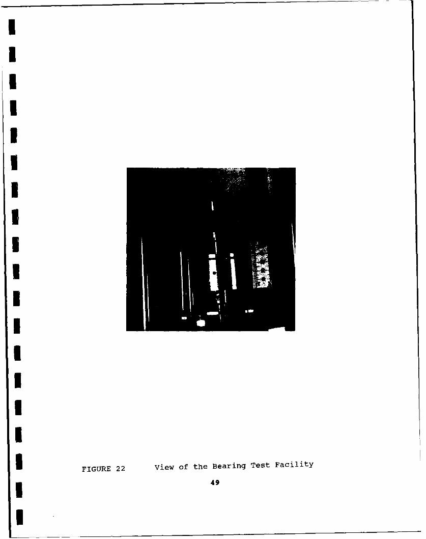
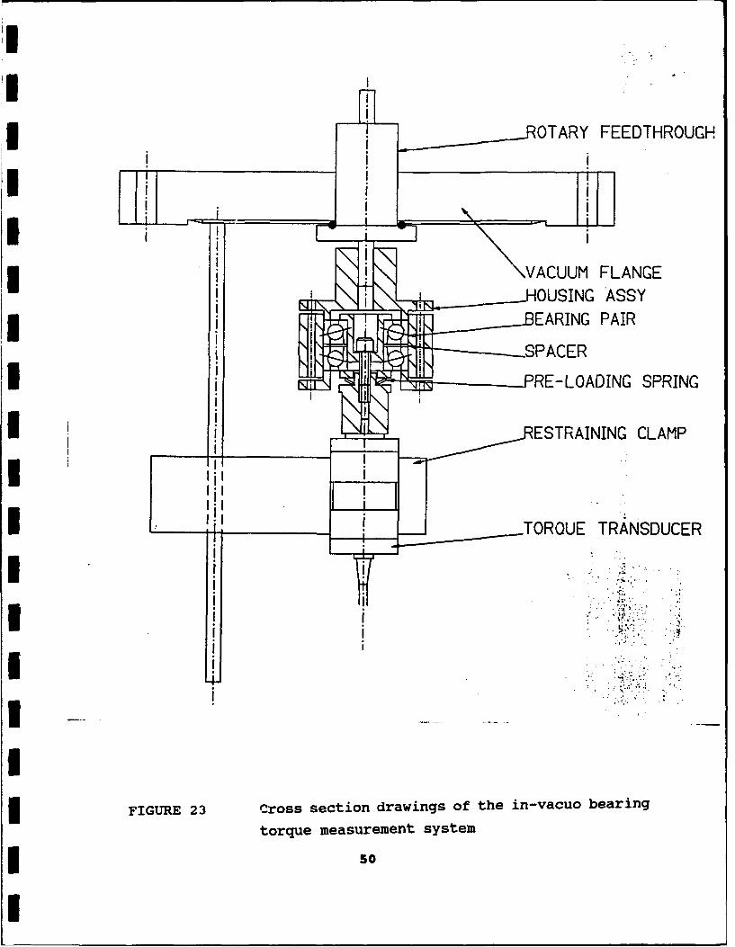
effects contributed to increased debris generation.The bearing test rig, and a cross section through the facility
are shown in Figures (22-23). Each pair of cages were fitted tobearings whose races had been lead ion plated in accordance with
standard NCT practice. The test bearings were purchased from SNFA,
and were of angular contact type ED20 to ABEC7 standard in AISI52100 material. Other bearing parameters are shown in Table 6.
* TABLE 6.
ED20 Bearing Size Parameters.
I Outer Diameter 42 mm
Inner Diameter 20 mm
Bearing Width 12 mm
I Ball Size 7.14 mm
Ball Complement 10
Contact Angle 150
Bearing Conformity 1.14
I48I
IIIIIiIUIUI
II-
IIIIFIUE2ViwothBergTetFcltI FIUE24iw9fteBaig etFclt
I
______-OTARY FEEDTHROUGH
I \ VACUUM FLANGE
HOUSING ASSYEARING PAIR
I RE -LOADING SPRING
IESTRAINING CLAMP
LI_______TORQUE TRA*NSDUCER
FIUR 23 crs seto rwnso.tei-a ern
torque measurement system
* so
I
I Each test involved a pair of bearings, with a "soft" preload
of 40 N set by the deflection of the wavy washer. The bearings were
rotated at 100 rpm for 2x10 6 revs, at test pressures between 10-6
and 10-8 torr. The average torque and the peak torque noise levels* were sensed by an inductive torque transducer and the signals were
fed to a chart recorder.
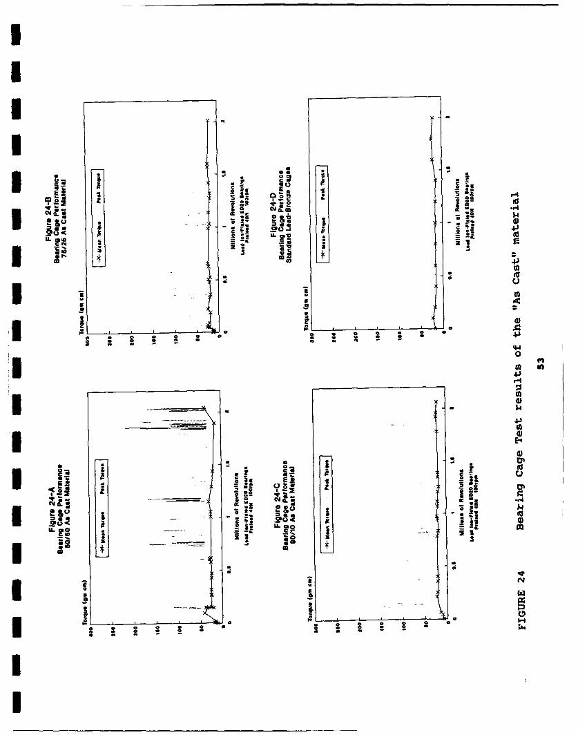
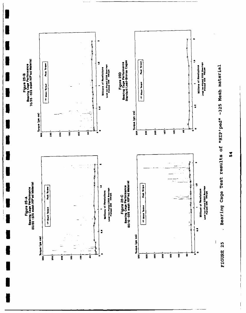
The bearing torque test results for the different alloys and
manufacturing methods are shown in Figures 24 and 25. Figures 24-D
and 25-D illustrate the results from a standard lead bronze caged
pair of bearings. Since all the materials tested can be expected tohave similar coefficients of friction in this mode of operation,3 the mean torque level for the bearings should be similar in each
case if the preload setting was applied correctly. The recorded
3 mean torque levels of 20 gm.cm, were the same in all the tests,
confirming that correct preload settings had been maintained.
The torque noise generated by the bearings is of importance in
rI comparison to other cage materials. Short lived torque spikes wereevident for all the materials. All the cage materials produced from
the supersaturated lead copper alloys performed better than thelead bronze for short periods, unfortunately at other times the
3 torque spikes generated by material transfer from the cage were of
a high magnitude. As can be seen in Figure 24-D and 25-D, the peaktorque noise levels for bearings fitted with standard lead-bronze
cages varies between 50 and 100 gm.cm. over the duration of the two
million revolutions. The key observations from our tests include:
* Peak noise levels increased with an increase in the leadcontent.
I * 50/50 "As-Cast" exhibited dramatic increases in peak
torque levels as the test progressed. This is probably
3 due to the transfer of large copper particles from the
cage (Figure 24-A).
3 * 75/25 "As-Cast" had a performance very close to that ofthe standard lead bronze (Figure 24-B).
I 51
I
I 90-10 "As-Cast" exhibited a better performance than the
standard lead bronze cage with the exception of a number
of short time periods (Figure 24-C).
• 50/50 and 75/25 "HIP'ped" cages registered high torque
glitches periodically throughout their tests, although
the magnitude of these fell as the tests proceeded
3 (Figure 25-A,B).
* 90/10 "HIP'ped" material initially exhibited very low
torque noise but this rose periodically as the test
proceeded, presumably with transfer of material to the
raceways following extended running (Figure 25-C).
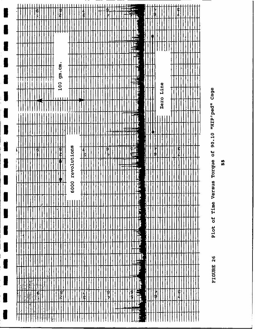
A segment of the time plot taken from the 90/10 "HIP'ped"
results, at the inception of the first major noise area around 1.2
million revolutions shows relatively high value torque spikes at
3 random positions on the trace (Figure 26). As the test progressed,
the regularity and severity of these peaks increased, but the
baseline torque noise levels stayed low.
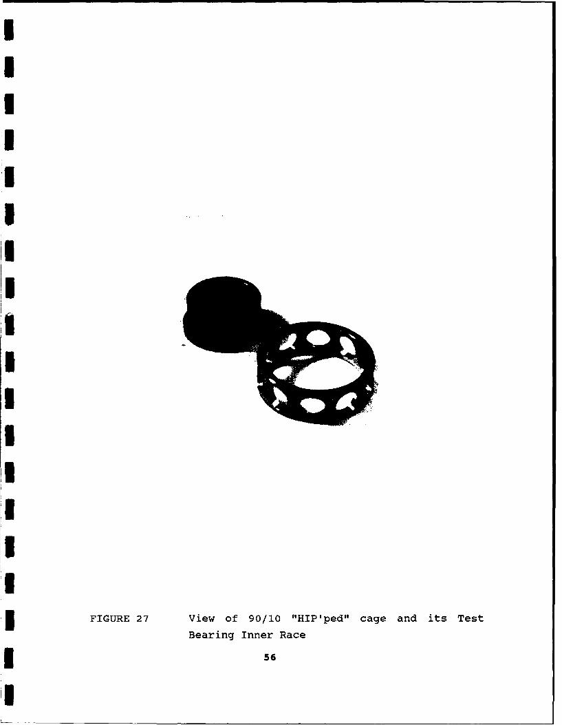
SEM examination of the cages after testing did not provide
conclusive results on the mechanisms for failure. In the case of
the 90/10 "HIP'ped" sample that provided the best performance,
examination of the inner race and the cage ball pockets reveals
only light wear marks, and the ball track on the inner race shows
only a small amount of transfer at the edges (Figure 27).
The 50/50 "HIP'ped" sample showed the worst performance, and
examination of its inner race and cage pockets reveals wear marks
that were darkened heavily compared to the 90/10 "HIP'ped" sample.
Substantial amount of wear debris was also present to the side of
the ball track on the inner race (Figure 28).
5.1.2. Gears.
Gears are widely used in space satellites for the generation
of high torque capacity when using low torque capacity prime
movers. The basic design of gears for use in space is as on earth,
52
I
i b i
2t to.
,.. 2 I._.
IIo = o o o1
U ia L0
00 a
0
....... .. .. ...... . 4 1
I a
I
4.)
________ IN0O
100
0 0L
aao
*0 022-a
~~t Ina :3 a.~a. 4G
a.30
- --
to~ : 2 2 0 4*0 00 :
IIIl L
40 a
a~ a" a
IIH
4-1I
0) E-0
E-4.
0
1 '0
I TIT
IIIIII
U3IIUUIIII
FIGURE 27 View of 90/10 "HIP'ped" cage and its Test
Bearing Inner Race
* 56
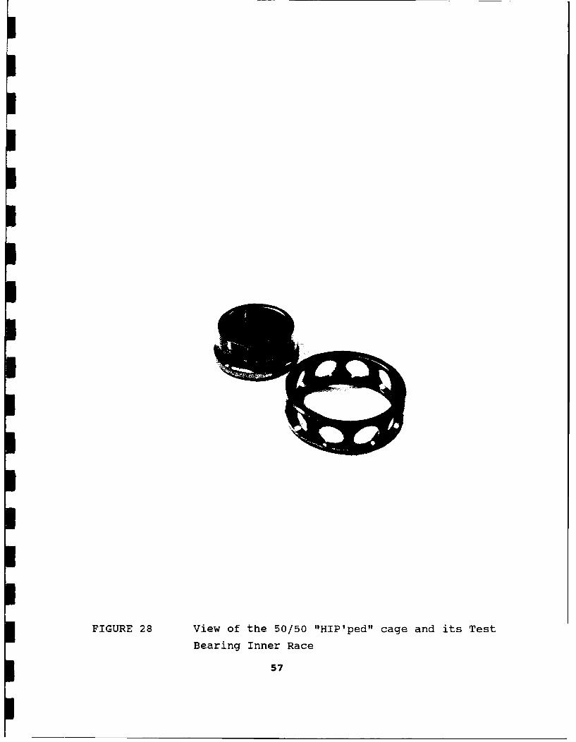
FIGURE 28 View of the 50/50 "HIP'ped" cage and its Test
Bearing Inner Race
57
the major design problem is to minimize mass while ensuring load
carrying capacity, and to choose a lubrication system which is
compatible with the space environment for up to ten year life
durations or longer. The choice of gear materials, and some
historical data for direct comparison with the results obtained in
this series of tests are provided in Reference 21.
To date, self-lubricating gears in space applications have
been limited to polymeric materials and the standard bronze
materials (21). Conventionally these have been employed in low
contact stress applications (typically <20 MPa). Medium stress
applications (typically 100 MPa) for dry lubricated gears, where
contamination by fluid lubricants could not be tolerated, have
employed gears plated with films such as lead or gold. Such films
always have a limited life.
A photograph of the four-square gear test rig is shown in
Figure 29. The rig was underslung by the stub shaft from a heavy
duty ferrofluidic rotary feedthrough, and driven by an external
drive motor. The steady at the lower end of the rig maintains
stability. The gear preload was locked into the system by rotating
the lower gearwheel, against the spring load, around the shaft and
locking in position. After initial trial testing, a load of 2 N/mm
face width (on the gear teeth) was chosen for comparison purposes.
The running torque of the gears was measured via the linkage arm,
which prevented the main body assembly fiom rotating.
The gear module used was 0.75 mm, and the pinions manufactured
from the various alloys had 41 teeth and a face width of 10 mm. For
the purposes of these tests, the counterface gearwheels were
manufactured from nitrided steel (hardened to 1000 HV) and had 120
teeth of 3 mm face width. All the gears were manufactured to
British Standards-BS 978 Part 1 - Class C (approximately equivalent
to AGMA 9). All tests were performed under vacuum, at pressures
between 10-6 and 10-7 torr, for one million revolutions at 100 rpm
and the torque levels were continuously monitored using a chart
recorder.
58
FIGURE 29 View of the Four Square Gear Test Facility
59
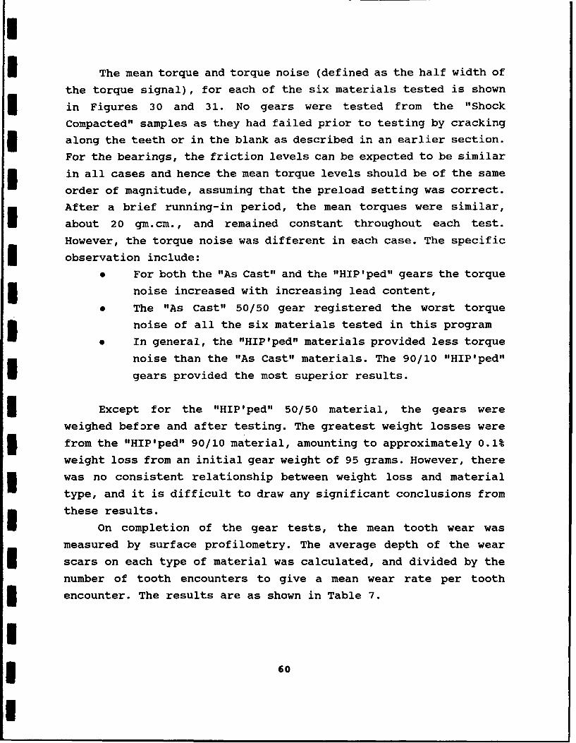
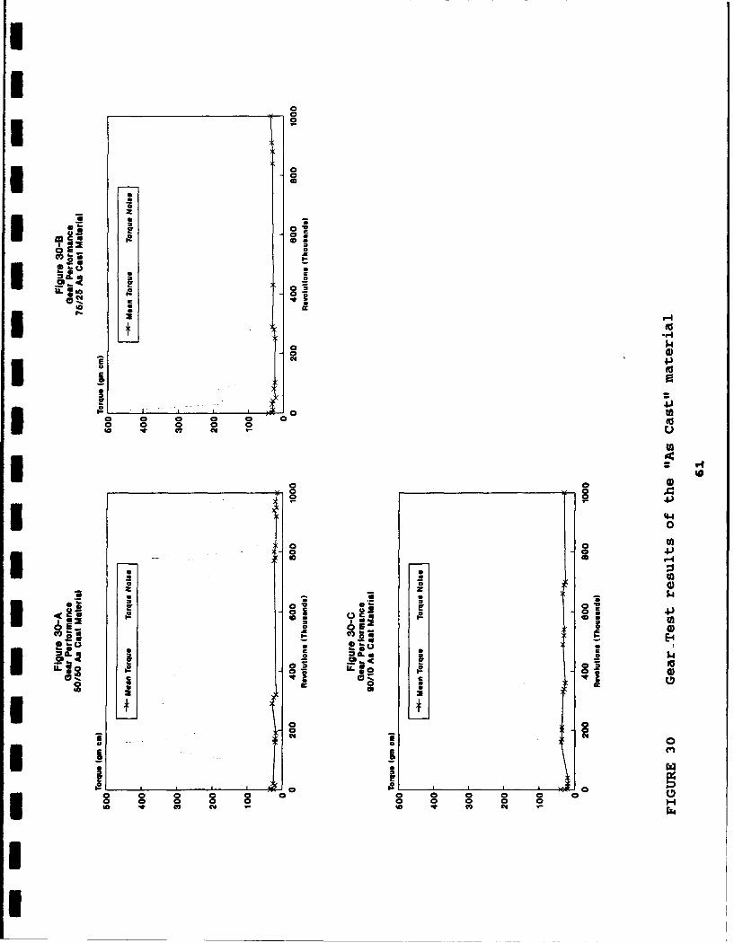
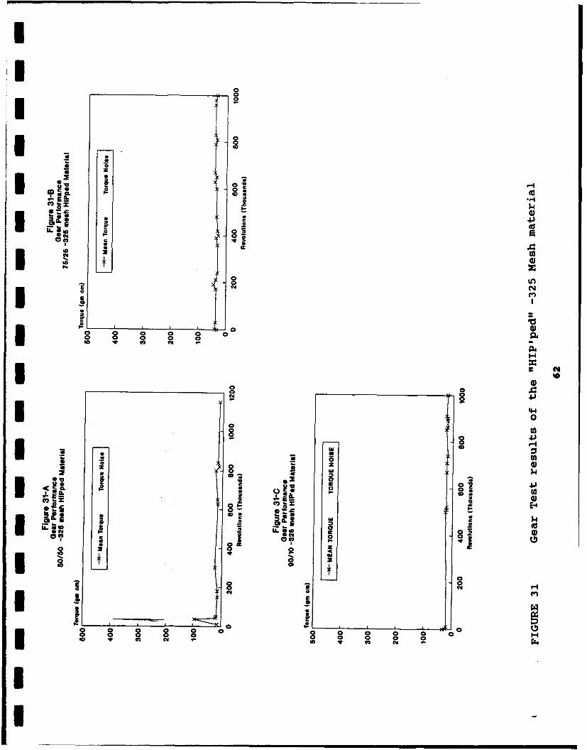
The mean torque and torque noise (defined as the half width of
the torque signal), for each of the six materials tested is shown
in Figures 30 and 31. No gears were tested from the "Shock
Compacted" samples as they had failed prior to testing by cracking
along the teeth or in the blank as described in an earlier section.
For the bearings, the friction levels can be expected to be similar
in all cases and hence the mean torque levels should be of the same
order of magnitude, assuming that the preload setting was correct.
After a brief running-in period, the mean torques were similar,
about 20 gm.cm., and remained constant throughout each test.
However, the torque noise was different in each case. The specific
* observation include:
* For both the "As Cast" and the "HIP'ped" gears the torque
3 noise increased with increasing lead content,
0 The "As Cast" 50/50 gear registered the worst torque
noise of all the six materials tested in this program
• In general, the "HIP'ped" materials provided less torque
noise than the "As Cast" materials. The 90/10 "HIP'ped"
gears provided the most superior results.
Except for the "HIP'ped" 50/50 material, the gears were
weighed before and after testing. The greatest weight losses were
from the "HIP'ped" 90/10 material, amounting to approximately 0.1%
weight loss from an initial gear weight of 95 grams. However, there
was no consistent relationship between weight loss and material
type, and it is difficult to draw any significant conclusions from
these results.
On completion of the gear tests, the mean tooth wear was
measured by surface profilometry. The average depth of the wear
scars on each type of material was calculated, and divided by the
number of tooth encounters to give a mean wear rate per tooth
encounter. The results are as shown in Table 7.
60
02
-0
0 $0 a)
Im V
0 C 0
~0~0
20 0
I0I0 4)
o) 0o-1
X 0
z0
0,0
E &'zS 4-)
Lne
E m
: :0 0
0 0 0 0 0
.44* 0
0 0 U0
*z 0 CcEn 02 ag
10 N 1.400) C
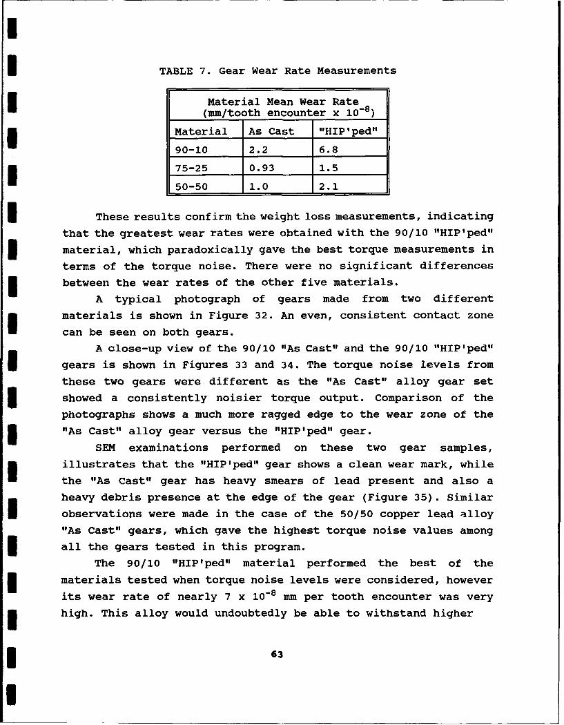
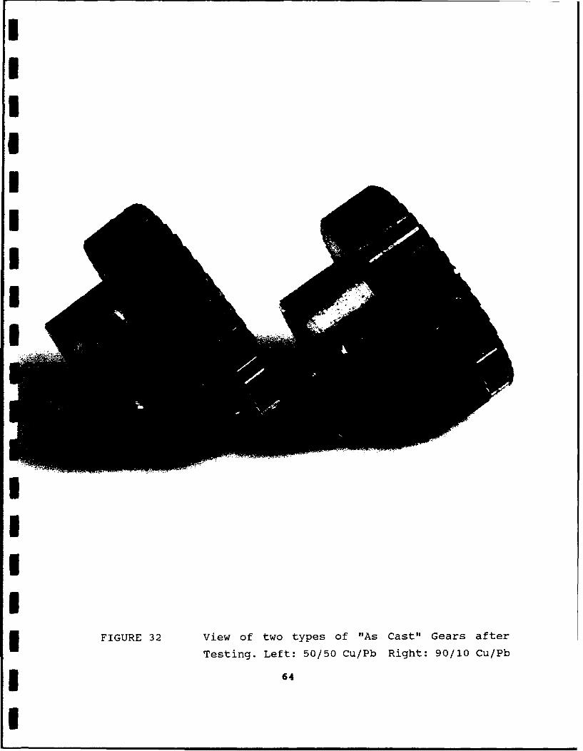
TABLE 7. Gear Wear Rate Measurements
Material Mean Wear Rate(mm/tooth encounter x 10-8)
Material As Cast "HIP'ped"
90-10 2.2 6.8
I 75-25 0.93 1.5
50-50 1.0 2.1
These results confirm the weight loss measurements, indicating
that the greatest wear rates were obtained with the 90/10 "HIP'ped"
3material, which paradoxically gave the best torque measurements in
terms of the torque noise. There were no significant differences
3 between the wear rates of the other five materials.
A typical photograph of gears made from two different
materials is shown in Figure 32. An even, consistent contact zone
can be seen on both gears.
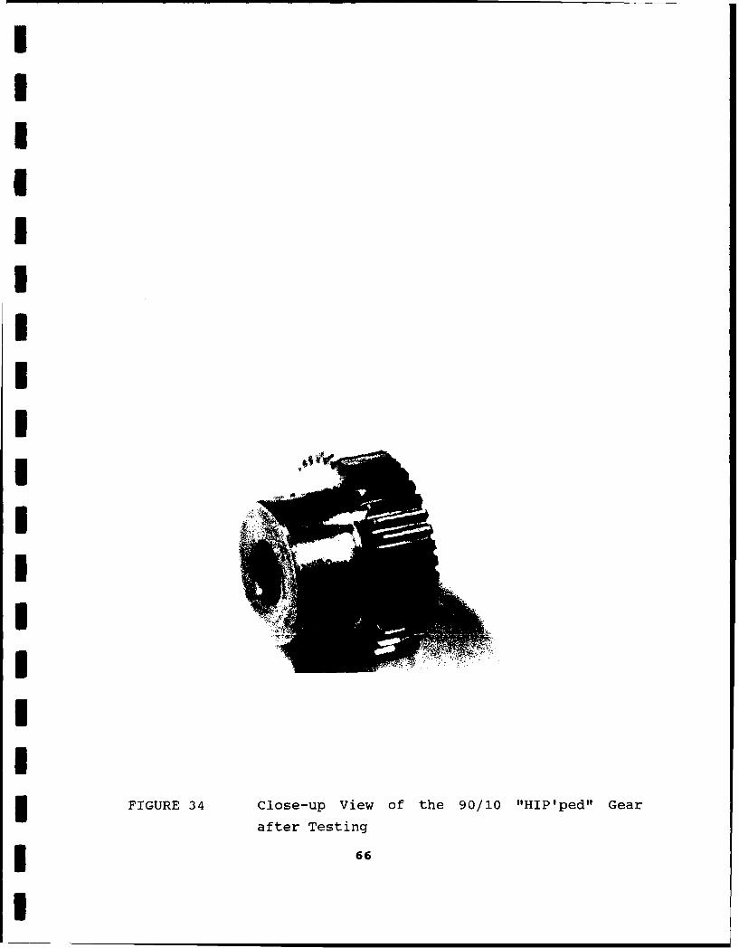
A close-up view of the 90/10 "As Cast" and the 90/10 "HIP'ped"
gears is shown in Figures 33 and 34. The torque noise levels from
these two gears were different as the "As Cast" alloy gear set
3 showed a consistently noisier torque output. Comparison of the
photographs shows a much more ragged edge to the wear zone of the
3 "As Cast" alloy gear versus the "HIP'ped" gear.
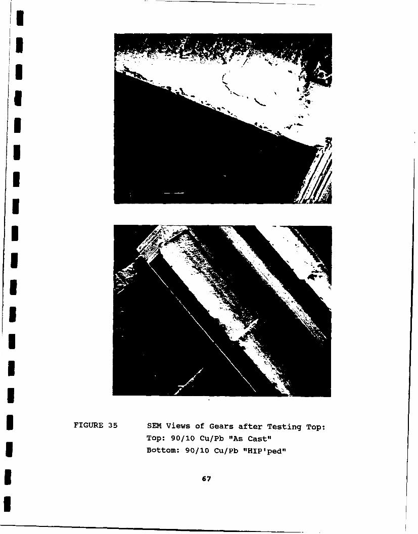
SEM examinations performed on these two gear samples,
illustrates that the "HIP'ped" gear shows a clean wear mark, while
the "As Cast" gear has heavy smears of lead present and also a
heavy debris presence at the edge of the gear (Figure 35). Similar
observations were made in the case of the 50/50 copper lead alloy
"As Cast" gears, which gave the highest torque noise values among
* all the gears tested in this program.
The 90/10 "HIP'ped" material performed the best of the
materials tested when torque noise levels were considered, however
its wear rate of nearly 7 x 10⁻⁸ mm per tooth encounter was very
high. This alloy would undoubtedly be able to withstand higher
63
IIIIII,
III
I
IFIGURE 32 View of two types of "As Cast" Gears after
Testing. Left: 50/50 Cu/Pb Right: 90/10 Cu/Pb
I
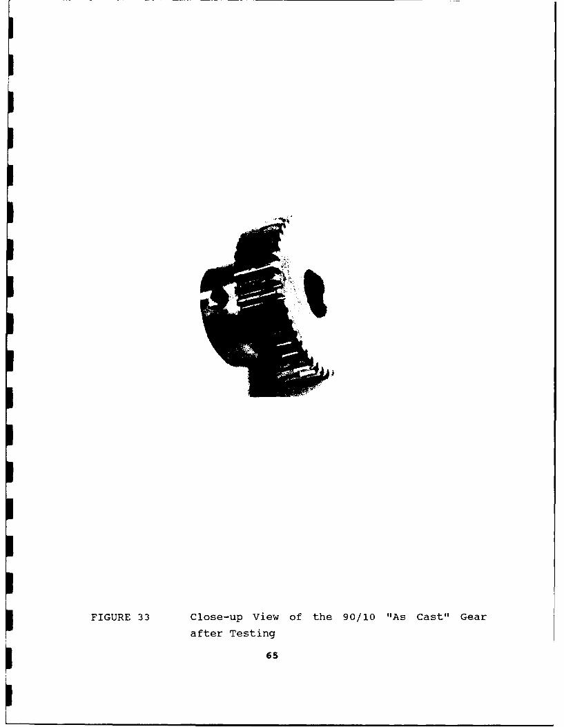
FIGURE 33 Close-up View of the 90/10 "As Cast" Gear
after Testing
65
mIIUI
I
IIIII
II
IFIGURE 34 close-up View of the 90/10 "HIP'ped" Gear
after Testing
* 66
I
I
'II
Botm 901 ../,. HI'e " ,a
I
III
=FIGURE 35 SEM Views of Gears after Testing Top:
Top: 90/10 Cu/Pb "As Cast"Bottom: 90/10 Cu/Pb "HIP'ped"
* 67
I• m
1
I contact loads, however the wear rate would increase commensurately.
Comparison with wear rates for plastic gears running against
I stainless steel wheels show the plastics to have much lower wear
rates at similar load capacities, example for Vespel SP3, a
I polyamide with MoS 2 , the wear rate was 6 x 10⁻⁹ mm per encounter at
a load of 7 N per mm of gear face width (See Ref 21, Table 8). The
higher wear rates combined with the weight penalty of the copper-
lead alloys suggest that future uses of these alloys in gears for
i space applications is unlikely.
5.1.3. Bushings
I There are a limited number of applications in space for self
lubricating bushings. These are normally in areas which do not see
continual usage, and to date have employed the standard proprietary
materials which are available from several manufacturers. There is
little data available about the performance of bushings in vacuum.
Reference 22 by Poncet provides some general data, and it was on
the basis of this paper that the test conditions were chosen for
this program. Previous experience at NCT has not been published in
the open literature and is limited to tests at contact loads ten
I times higher than those used in this program.
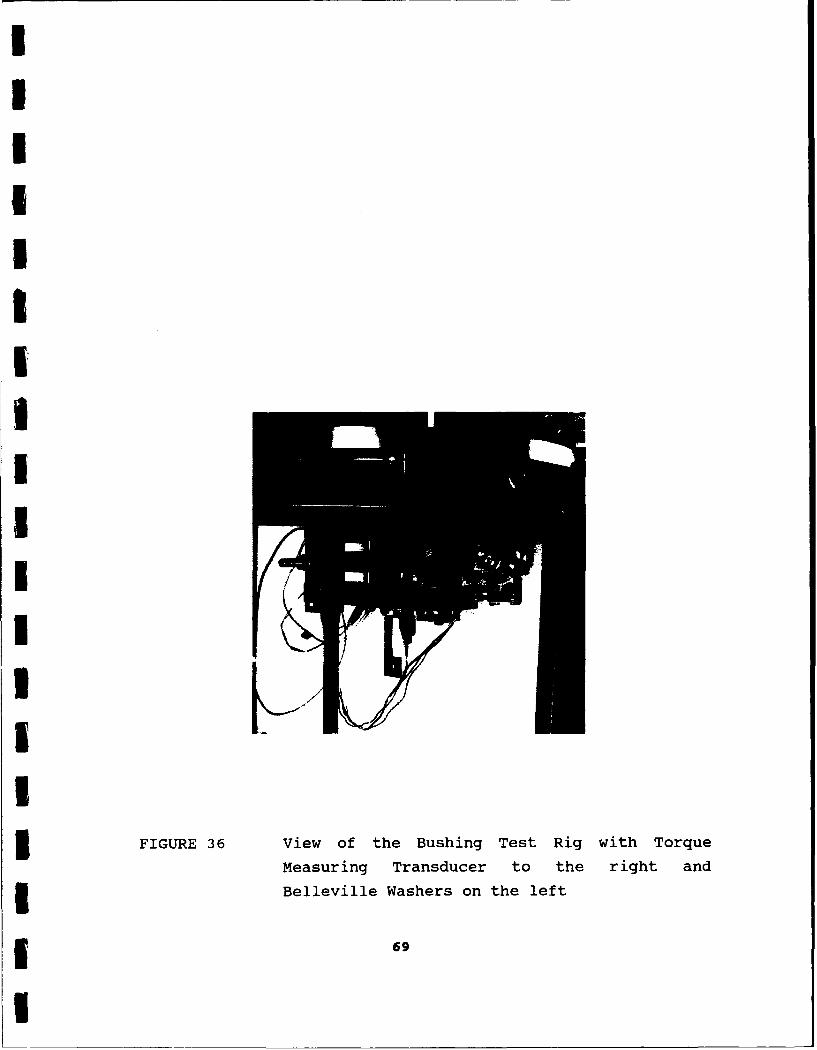
A typical rig is shown in Figures 36 and 37. The rig is
underslung from a heavy duty ferrofluidic rotary feedthrough and
driven by a motor/oscillatory crank mechanism external to the
vacuum chamber. The bush is clamped into the central lever arm, and
is loaded against the stainless steel test shaft (typically 180 HV)
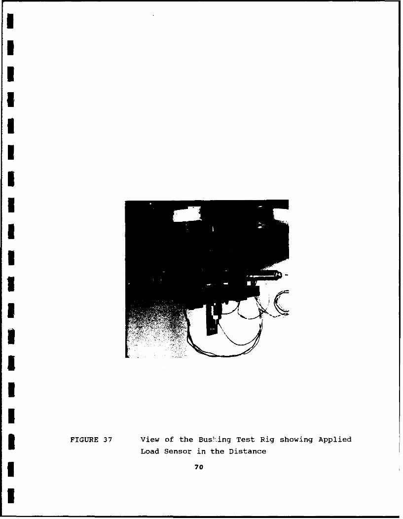
by the stack of belleville washers seen in Figure 36. A load sensor
on the opposing side, Figure 37, was used to set the load levels.
The frictional torque generated is measured by the load cell, which
I supplies the torque required to restrain the free-swinging test
section. All opposing shafts were manufactured from 316 stainless
steel to a surface finish of 0.4 microns CLA. The bush hole
diameter was nominally 20 mm with clearance toleranced between
0.01-0.05 mm.
68
II
IIII
I
3 FIGURE 36 View of the Bushing Test Rig with Torque
Measuring Transducer to the right and3 Belleville Washers on the left
1 69
I
IIIIIUII •=II
II
IFIGURE 37 View of the Bushing Test Rig showing Applied
Load Sensor in the Distance
I
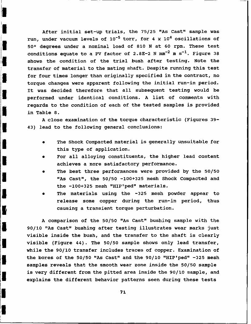
After initial set-up trials, the 75/25 "As Cast" sample was
run, under vacuum levels of 10-5 torr, for 4 x 10⁴ oscillations of
500 degrees under a nominal load of 810 N at 60 rpm. These test
conditions equate to a PV factor of 2.8E-2 N mm- 2 m s-1. Figure 38
shows the condition of the trial bush after testing. Note the
transfer of material to the mating shaft. Despite running this test
for four times longer than originally specified in the contract, no
torque changes were apparent following the initial run-in period.
It was decided therefore that all subsequent testing would be
performed under identical conditions. A list of comments with
regards to the condition of each of the tested samples is provided
in Table 8.
A close examination of the torque characteristic (Figures 39-
43) lead to the following general conclusions:
* The Shock Compacted material is generally unsuitable for
this type of application.
i For all alloying constituents, the higher lead content
achieves a more satisfactory performance.
0 The best three performances were provided by the 50/50
I "As Cast", the 50/50 -100+325 mesh Shock Compacted and
the -100+325 mesh "HIP'ped" materials.
I The materials using the -325 mesh powder appear to
release some copper during the run-in period, thus
3 causing a transient torque perturbation.
A comparison of the 50/50 "As Cast" bushing sample with the
5 90/10 "As Cast" bushing after testing illustrates wear marks just
visible inside the bush, and the transfer to the shaft is clearly
visible (Figure 44). The 50/50 sample shows only lead transfer,
while the 90/10 transfer includes traces of copper. Examination of
5 the bores of the 50/50 "As Cast" and the 90/10 "HIP'ped" -325 mesh
samples reveals that the smooth wear zone inside the 50/50 sample
is very different from the pitted area inside the 90/10 sample, and
explains the different behavior patterns seen during these tests
71
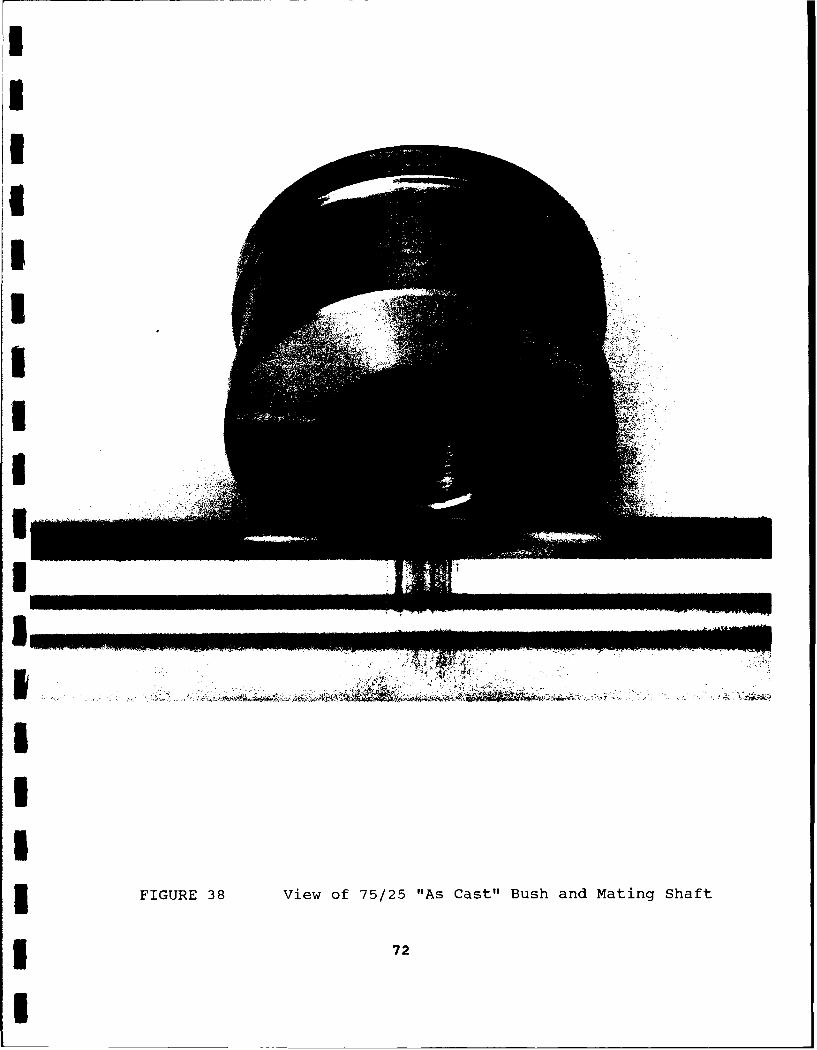
II
II
I* IUE3 iwo 52 A at uhadMtn hf
I
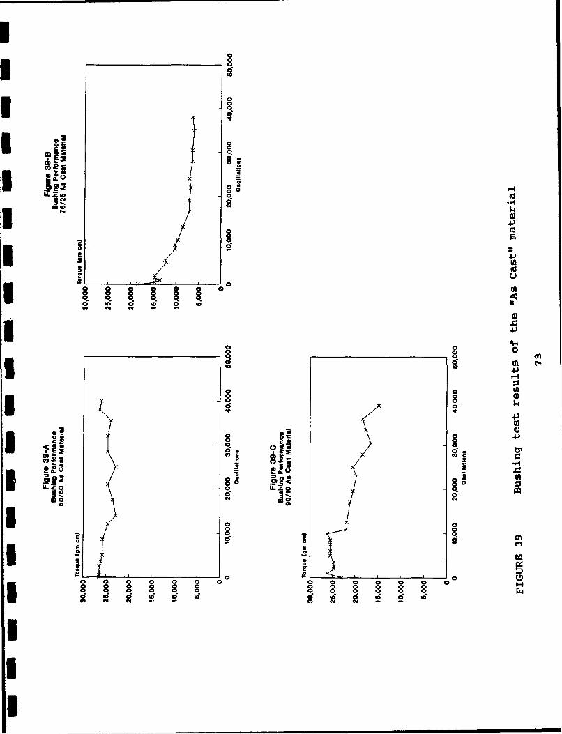
I0OC
0
C, r-4
,t- $4
ILta 8~u
4-)
0 4)
co COC) Ct10
0 0 0ai
toi C - b C l 0 '0 d -
oy 0)cm
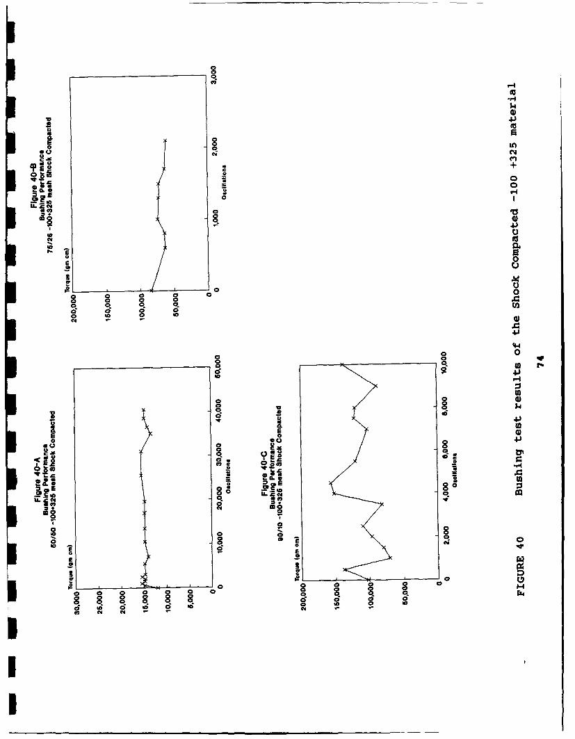
$4
U 4)
CLU
E aL
a +Odl C1z. Ica,
4)
0
o .0
0 0
Cdd
E 4)(44
oo 0o. 0S 040 0
r E)2 '4
q 0. cm
-4 8
.1 4
66 C4
8l 04
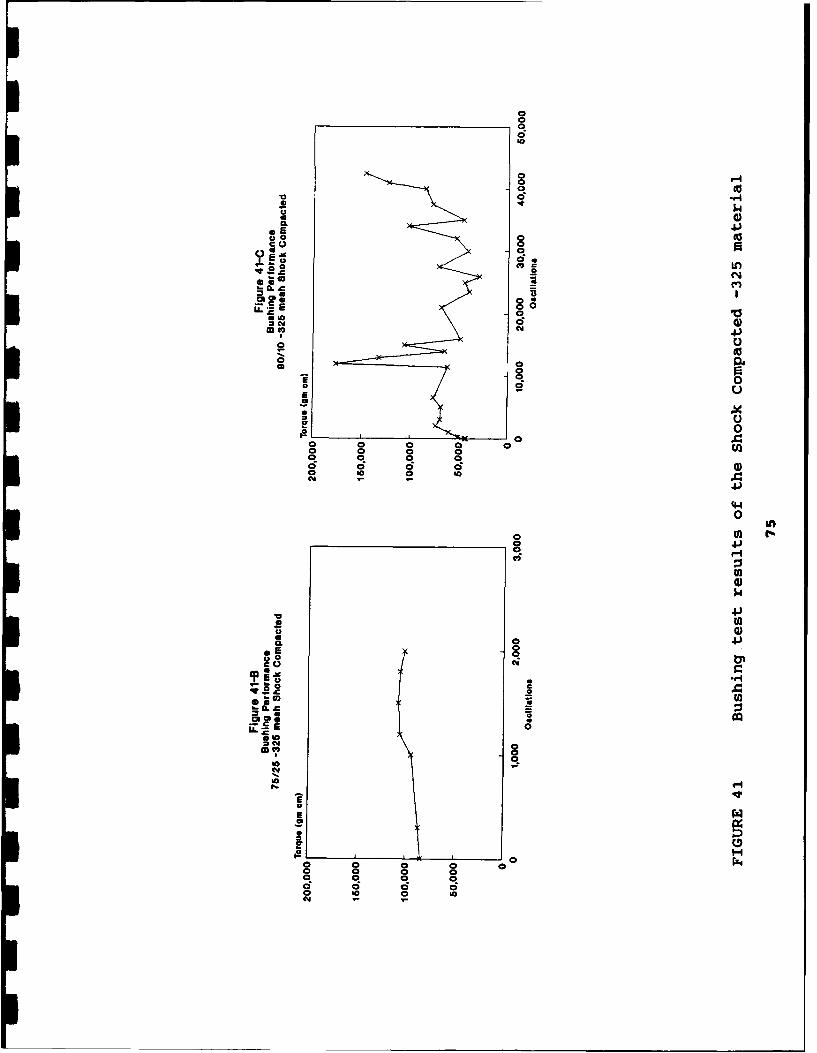
V0
0 0c6
0 L0
a oa
co. 00
*0
CIA
V
000
4-)U
o to
Z FA
.9 0
oto
44)
Ct-100
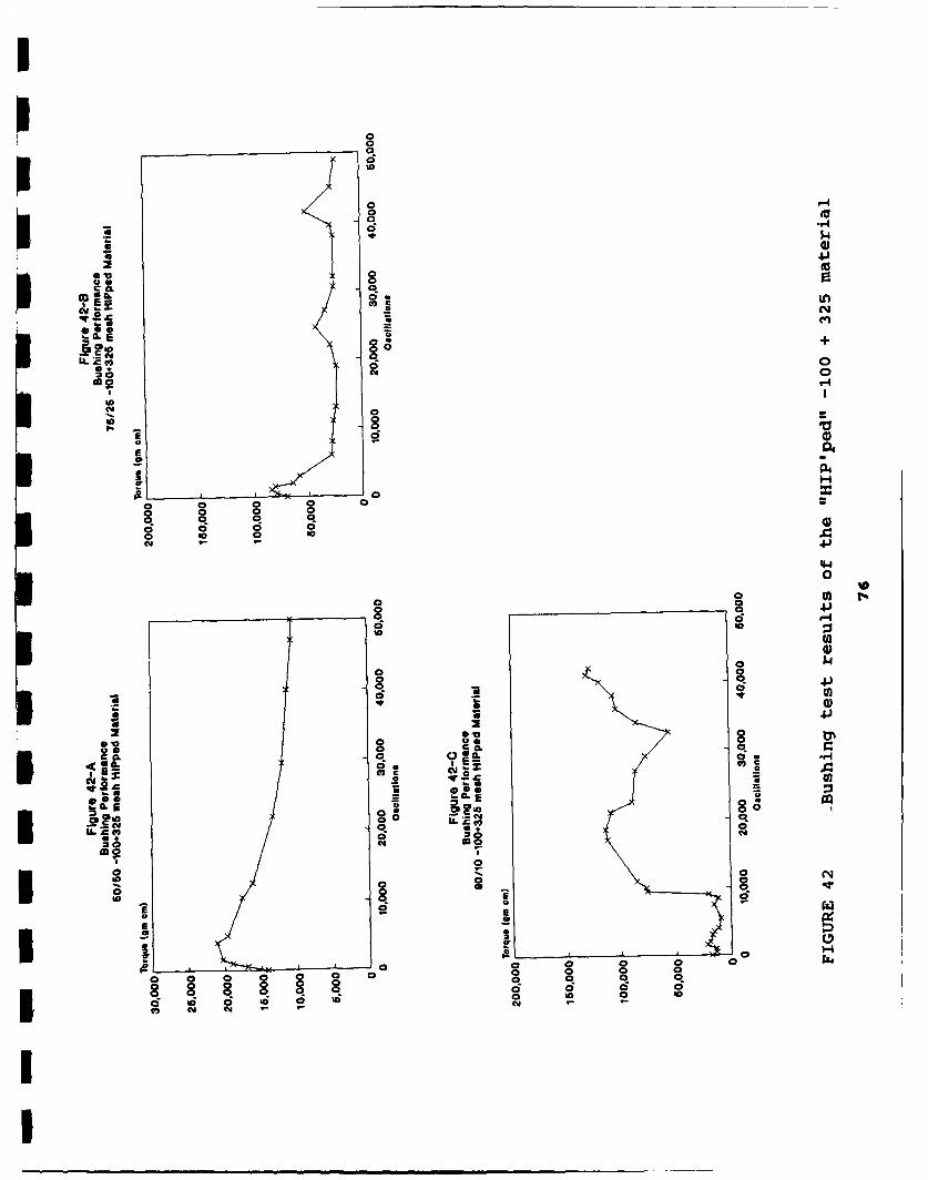
II1m o
100000
l00
o M7
s~o 4)0 $4.
8u 0Ud0
O'-I
EE
o 0y 0x 0
c o aos C 0
400
to d
0
0 S a0
CI
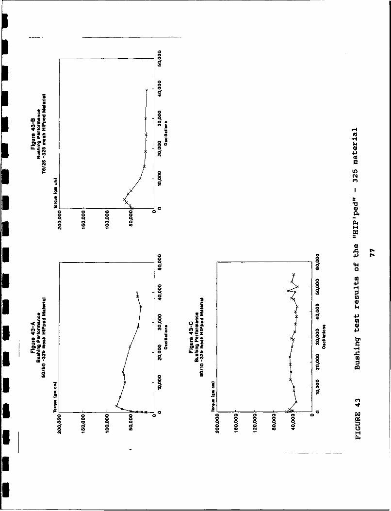
0
aaOZ 0
10 0
C C;
0~ 0
v to
L 00 LL loma c
C0
00 0 0
a 0 0 0
CQ)
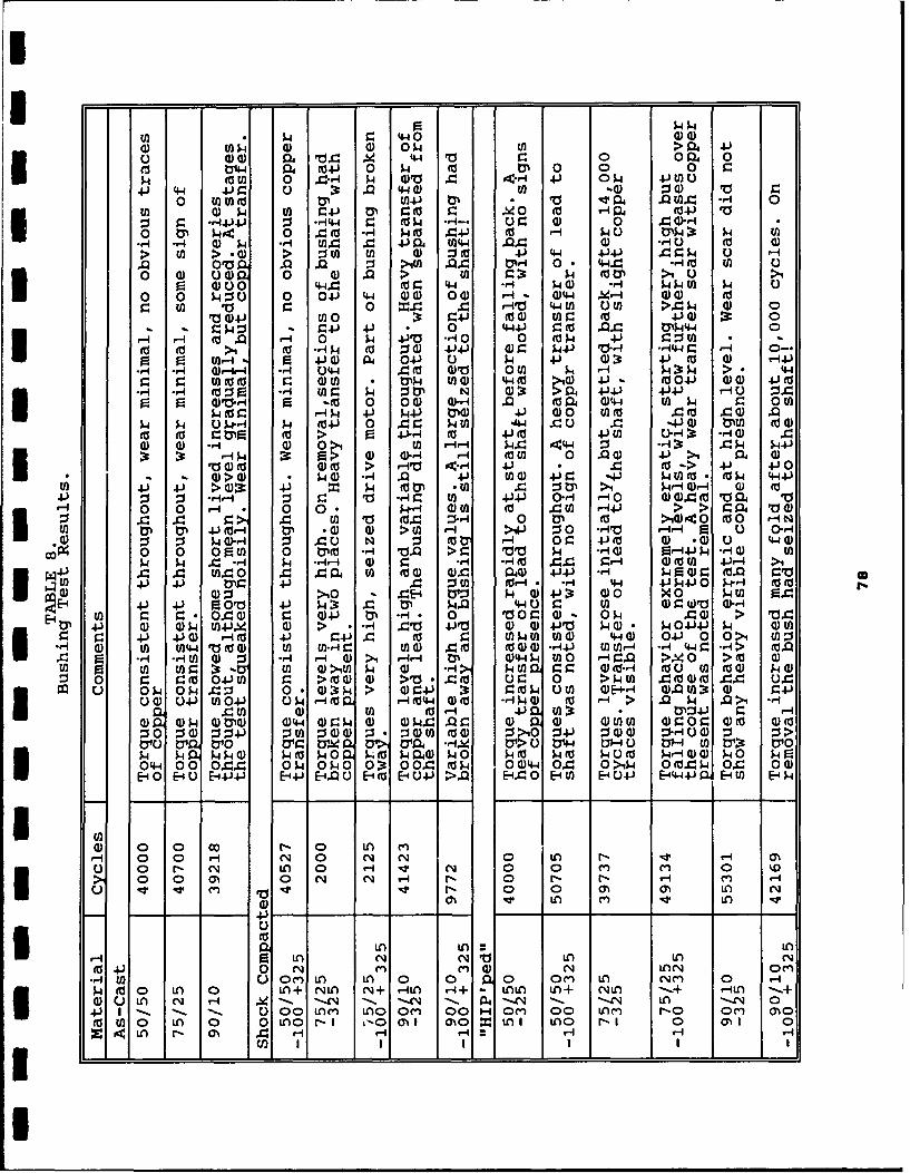
U) t 4 9: (440 (L)(10) 4) (0 0 O4 W U) -0. 00W P4 9 44 r.V 0 004 0
0'44 04 04-) 0 P- 0) 0 0 0 z(a M 0 ~r,-tq p. Oro .4 4H 41-) 0 p4 4-1 t)C.
4.) 4-4 4-) z .3 0 4-44) ED Q) 04 V0 z0 tnFA(d W4-) 0 ro e V4 4 .W4 ~-4 0
U) 0L p. M) Z41 M Z 0 9 40 (o w-404 (041 VcSr -144)W. 0 -H44 r. M pU "-H- 014 0 0 4 W*-H
0 tP ý4 0 r. (o *Hq $403 .44- t r4q ý4J 0 U)g P
3q 0 r 0 ) ý4 0q W 0 04. tA44 4r. 0W rq E)e 00 o (> ) w 1 0 M (n (1)-3to V 44 4- >.L2i0 0:u ý
A r a 10 A4 41 *4 r. t 0 4 4414 .Qq -IVN U 00- a)4 (u ) a - 0 4) 4 >' --0) r p t 0 ) (UP u1 >
0U ( (UO *'-4P to 9 4-41 H P~ W~ V.11 *-44I 4 0-.p
0 0 k 0 04J 44 0)a) 04) - W. ~ 4-4 gr- (1)4 (1) (1
ra 44 En 0 941 w o-'t w 90 414 3: 0)
=1 4 4j %0 r.4- 4- P 444J r.1 (o 44 MP-44 0) (= -s i 0> *- ~.0 p 4 ia -41 0 0 4Jo p .4U)((r .:%-M %
4o it11 ( -1 P'i~ 0 V W'I U)4 414 MV4 V-40 -144 UV VZrf
0 0 M'-4 * 0 0 4 04-1- W (U 41) ~4):r 4. fu 4) 14
r. .9 to oty . ) V Mm ) a Z' 4 40 a) (U >iO J )(U) 4-).H - m: H1U- M r.0 p 0 u >0) a)- >i M0 4J-)V '-- r- u 0~4
wC* %ti 0 0 W1- W.-r 4 0 14 44 E 0. 0 r. 0 M
41 - a 90 41 I P3 4J W-) PQ) 4J W M 0 M) .~) 0 4)-ý4 $4 U.0r0 X 041) 0 loo 04 V0tl -4P r.0 U V0-j ) Mh
-3 41 0- pP U)r1 0 (1 *- *.-4 caV W1 0 4 4V P0* P4141 P4 4)T5U))t (1)-'4 to0 > ~ ( (U0.44 4- 4 C 0 > 4.
4U) U Q-400 4J P M'~ t4 4 0 ON >4 prID 0 )104-)-I -'-4W 0 r4 '- > '-Ho- w 44-4. ) O-r >.q 0>)(4to U 04 o
0 0 410)04 oP-4(W '-(44(n -'(o (U V-4>J >P £> r -.4 v01U 01 4U(rI P ( ) W >M -4 >,P (10: *- rr4 R u '-H
0 0P4W!W 0 r.40P u N Wmt - 0 r JV 4 WU 440 04 0 ~ 00 (CP 004-a-qV4>r.f 4 ,q 04-) 0-441P 0-14 00
pEp 4 H 04- a r rq E-i d.~0 E4 HO-P Ea) (o4-to E-U) E-4
w 0) 0 0 Co N4 0 LA X: Na 0) 0. 14 4-) -4 p9a A gN coo o 41 M '. : -I (L)4 0 $44N 0 LAP Itw- 00o) NQ( L 0 >40 r.& (N0 0 C) 0 p MoE 0 V ' 04 Ord vN p :4w -4 N 0 . W w 0 Wca W-4
to r. r r 4) 'r. W~ LA -rI- 0 r .() O 9) > 1
-, - M Q 0 r'L LA 0- 1 ýrl ) W4ý 0 0- r.4 LA0 >J 0t 4)P n Mr ý t (n LA 0It pA NA (N+ .4 $44 VW 9:L LA+ wN *- .+ toA (-W.+ p
0 0 LA (N 04-. w5 9 >00 w L >Vg 4( U 9.% L ) A '(o 0Dto 4(uO LA p0m 0LAONI >4 r4 ý :0$ 0-0' tfOLA LO NI 0. to I 0:a ..
00 o*- z 0-1- OOL~ U)0c Z O: :1()t(00 :% ý 00J LWW NOr On) 0 >
~E -LA 0~ E-4 U vJ4 -44 E- w - ( - V>4 -4: 4 0 -4 En HU- w-44. a -4W 4
ON IV Inm le34I0
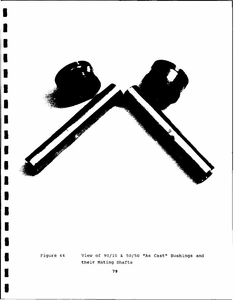
,
I
Ii?
I-2
UIIII F g r 4V e f 9 / 0 & 5 / 0 " s C s " B s i g n
Ihi aigSat
I
(Figure 45). These observations are typical of the transfer
patterns seen for all the other samples in this program.
On the basis of the catastrophic failures seen with some of
the other shock compacted materials, the choice for further
consideration resides between the "As Cast" and "HIP'ped" -100+325
mesh 50/50 materials. Since a torque load of 20,000 gm.cm. is
equivalent to a friction coefficient of 0.24, it can be seen by
reviewing Table 7 in Reference 22 that the "HIP'ped" material
compares to the Glacier DU material.
Since bushings are usually produced by sintering, the copper-
lead material in the powder form may very well be suitable for more
extensive testing, dependent of course on the envisaged cost of
production of such bushings versus the industry w-ide accepted
standard Glacier DU manufactured by Glacier Metal, U.K..
5.1.4. Brushes.
Current pressed MoS 2 /Cu/Si composite brushes u- for
electrical communication have limitations in terms of their
electrical noise and wear - particularly for low earth orbit
applications. NCT has tested several methods for brushes (23). The
problems with brushes currently in use in space mechanisms with
regard to their susceptibility to contamination and the subsequent
effects on their electrical performance is summarized in Reference
24. These materials can also cause small regions of high resistance
on the opposing slip-ring, while the surface of the slip-ring
(usually silver or gold plated) can suffer from tarnishing, which
leads to higher contact resistances.
The small brushes were soldered to beryllium copper cantilever
springs and pressed into contact with silver coated slip rings of
25mm diameter. An overall view of the slipping test facility and a
close up view of the brushes in contact with the slip-ring is shown
in Figures 46 and 47.
s0
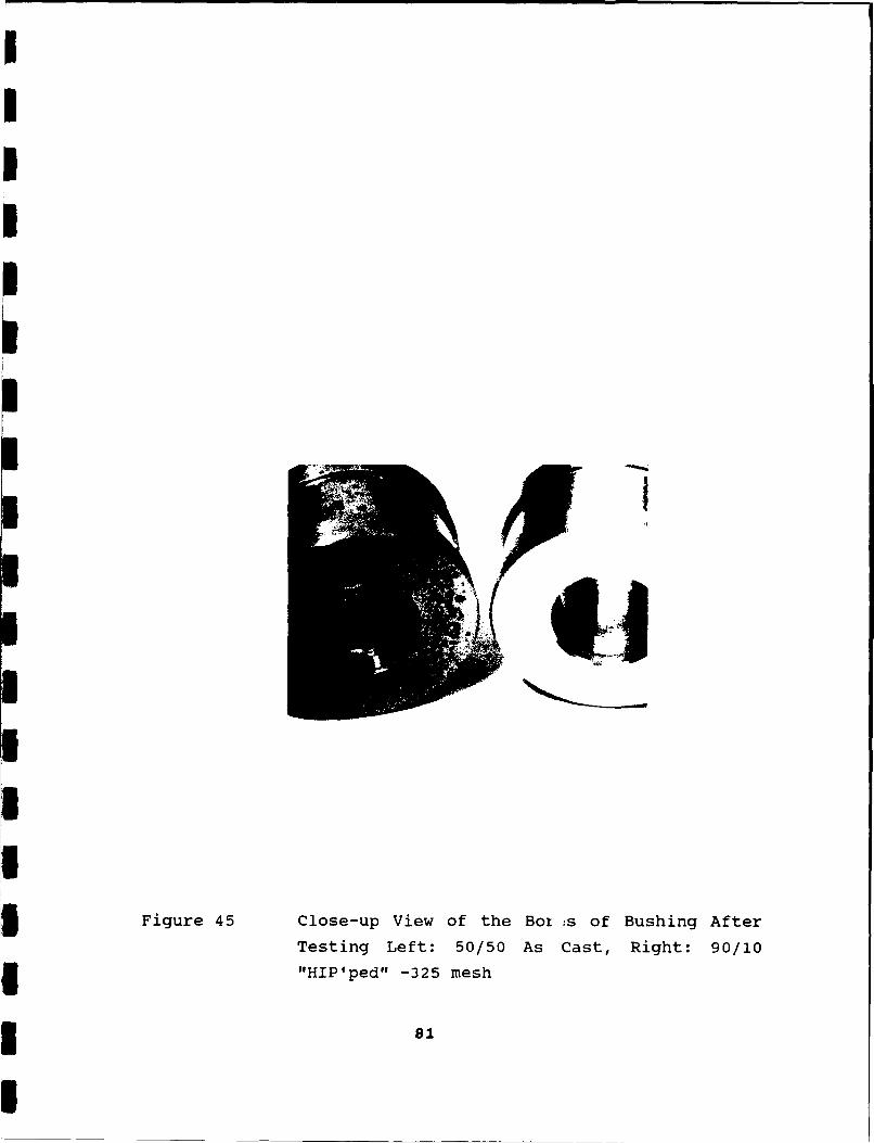
Figure 45 Close-up View of the Box :s of Bushing After
Testing Left: 50/50 As Cast, Right: 90/10
"HIP'ped" -325 mesh
81
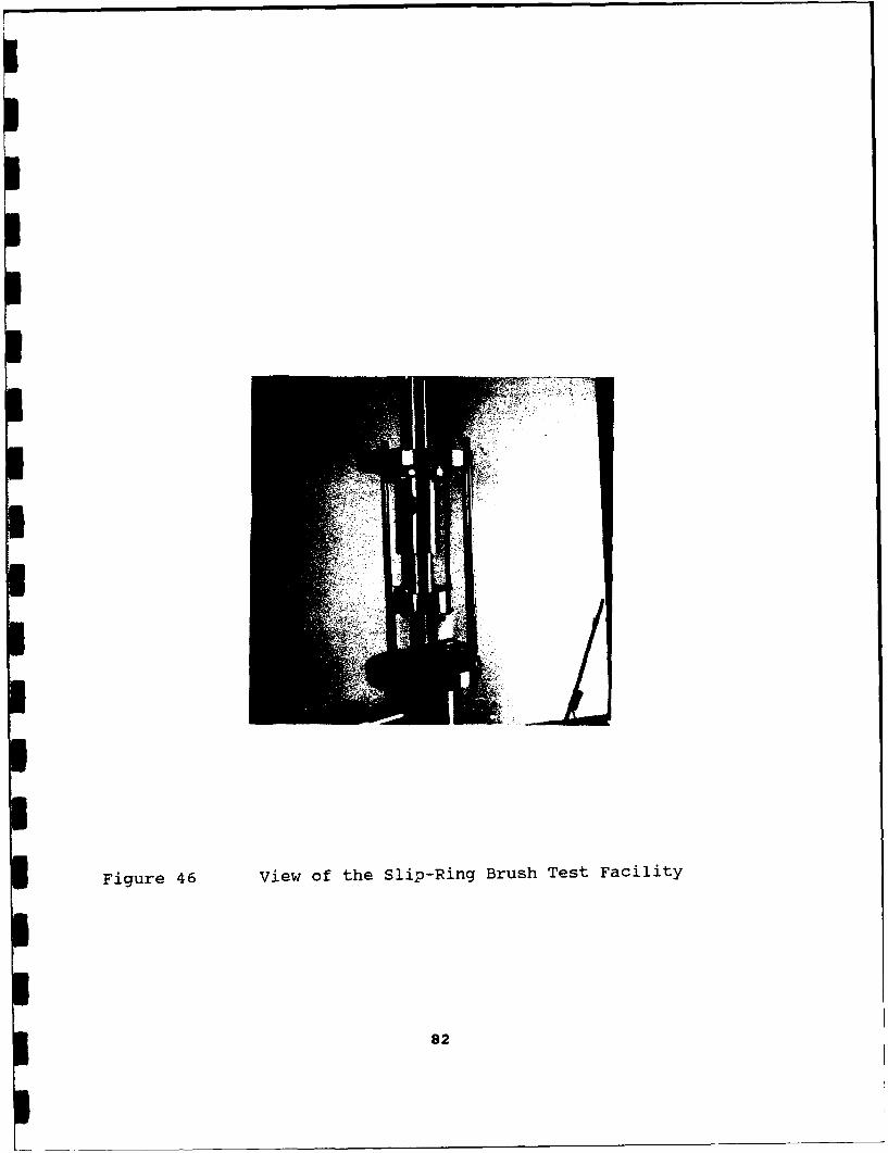
Figure 46 view of the Slip-Ring Brush Test Facility
82
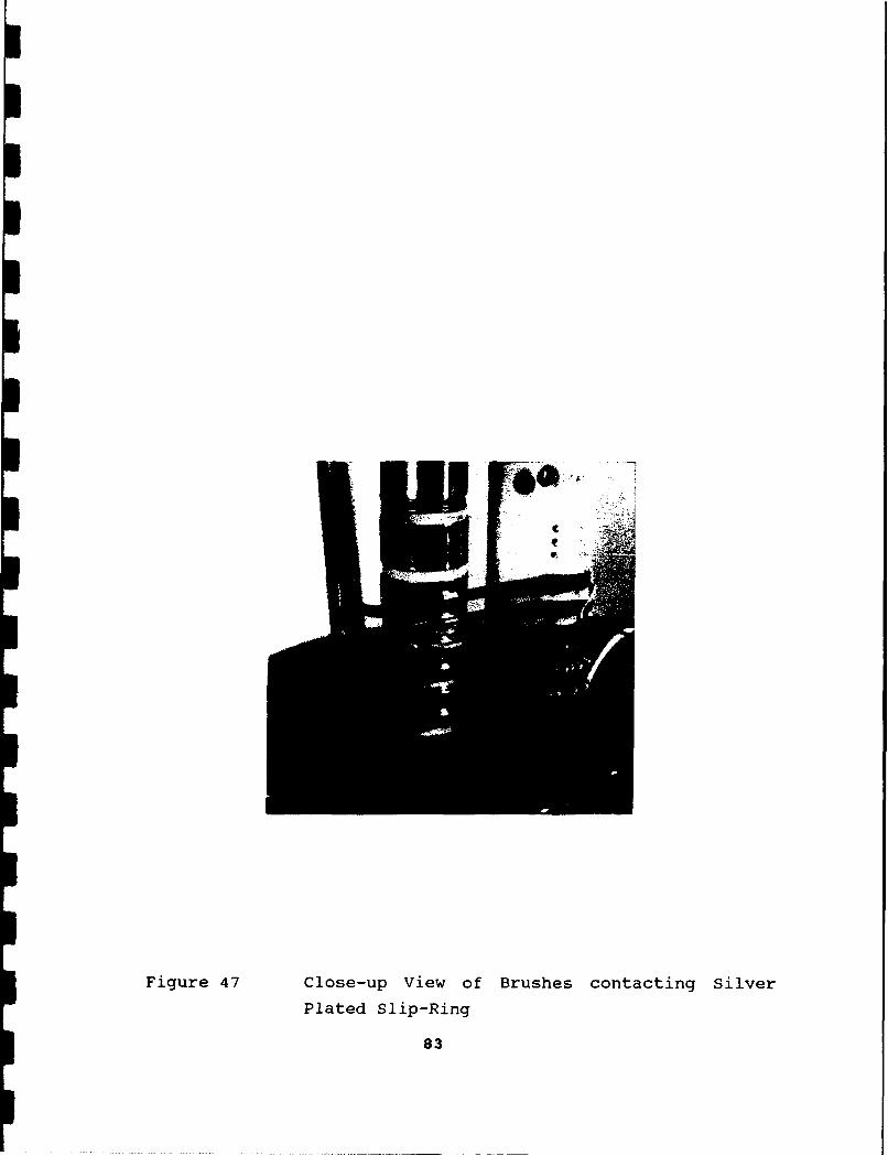
Figure 47 Close-up View of Brushes contacting Silver
Plated Slip-Ring
83
The mean load on each brush was set to about 0.6N. Three pairs
of brushes were tested simultaneously. A constant current supply
was used to feed a current of 2 amps through each brush throughout
the test, as shown in the schematic diagram in Figure 48. The slip-
rings were rotated at 100 rpm for 10,000 revolutions, in vacuum at
a pressure less than ix10-6 torr. The voltage drop across a pair of
brushes was monitored using a digital computing voltmeter, and used
to calculate the contact resistance of that pair of brushes. The
voltmeter was used to compute the maximum, minimum and mean voltage
drops across pairs of brushes during 30 second periods, usually at
intervals of 1,000 revolutions of the slip-rings, but more
frequently at the start of each test. The brush dimensions were
measured before and after each test, but the actual wear seen was
too low to make meaningful assessments of the specific wear rates
of the different types of material.
The measured resistances for each of the nine types of brush
material, as a function of the number of slip-ring revolutions are
shown in Figures 49-51. The general observations are:
* Increasing the amount of lead demonstrated an improvement
in the performance in all cases.
* "HIP'ped" materials, (Figures 51A-C) produced low
variations in the mean resistance throughout their tests
and the superimposed peak resistances were only slightly
greater. These brushes were the best compared to all
others tested in this program.
* The 50/50 "As Cast" material gave a performance similar
to the "HIP'ped" materials.
* The 75/25 and 50/50 "Shock Compacted" materials, and the
90/10 "As Cast" material, showed some variability in
their mean resistances, and high peak resistances, during
the early stages of their tests (up to one or two
thousand revolutions of the slip-rings), but then behaved
similar to the "HIP'ped" materials.
84
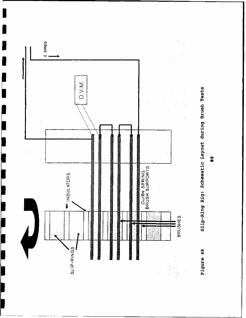
C,)
jEijio
C~U)
$4
Ee
0
>4
U) H
M- z A
U) EU
0%
C))
0 co
EEn
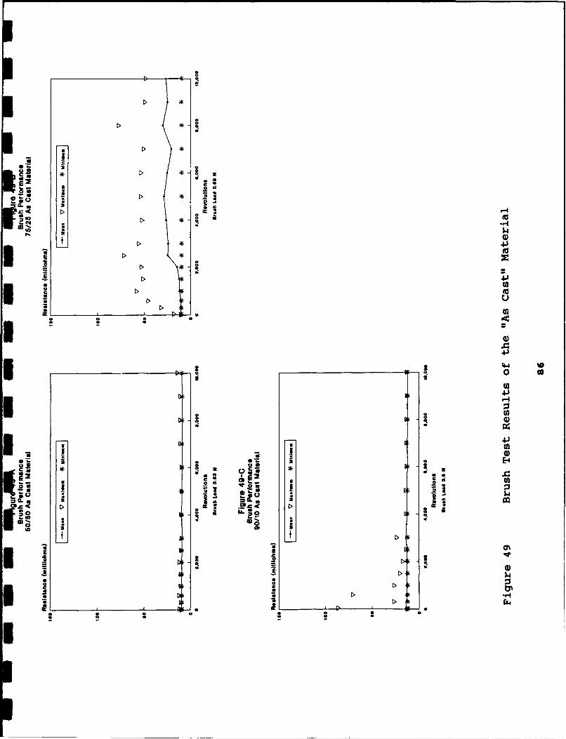
0 c
2 0 2
uWO
C>.
C 44
2~0)
EE-4
02 lk
v %)
ok 3 t. a0U !)
0,040.
C C a
Cc U
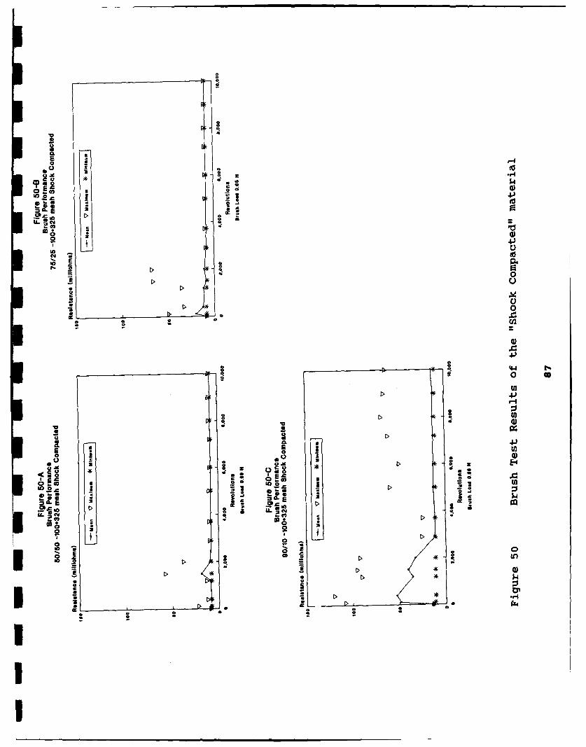
QS
E0
co
am
0.
0 22
-~0
CL.00
o C2
I0
20 0
.CC
0 -0CO',
Co Z 04
*v co
CF) +
'a
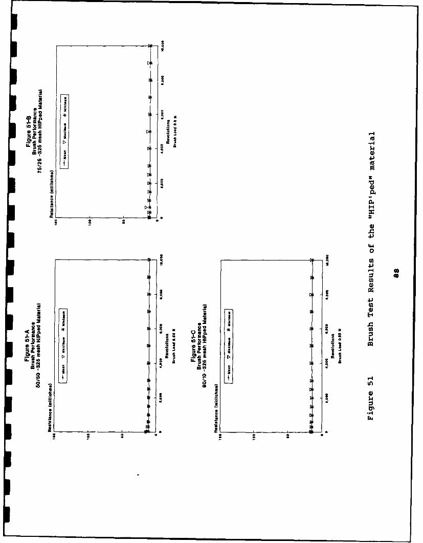
00
itS 0
00
.4.*00
o 00-00
04
E-4
-00
to 0 a
* C c
0. 0 0
The 75/25 "As Cast", and the 90/10 "Shock Compacted"
materials gave the worst performances, with high peak
resistances, and the greatest variation in their mean
resistances throughout the tests.
SEM examination of the brush condition after testing shows a
large wear zone with ragged edges in the 90/10 -100+325 mesh "Shock
Compacted" brushes (Figure 52). The. observed wear zone is
consistent with the noisy contact resistance observed throughout
testing.
The 50/50 -325 mesh "HIP'ped" alloy brushes ran very quietly
in terms of contact resistance throughout testing and this is
consistent with the clean wear zone with no sign of raggedness in
the contact area. These are representative of all the test samples,
and provide pictorial evidence to support the test results (Figure
53). The "HIP'ped" materials were however all very successful, with
low resistance variation throughout, comparing very favorably to
the historical data both in terms of contact resistance level and
variation.
However, this noticable improvement may not on its own be
enough to generate further interest by the space community since
the friction levels and high wear rates (as shown by the gear test
results) may act as negative influences. If this market is to be
addressed seriously, then a further extended period of testing
varying speed and load would be required to show the limits of
performance, and to allow proper wear rates to be measured on these
specific items.
89
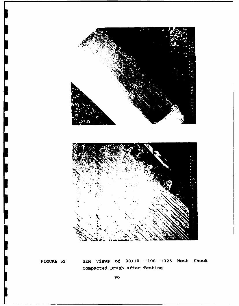
4jS
I I.
FIGURE 52 SEM Views of 90/10 -100 +325 Mesh Shock
Compacted Brush after Testing
90
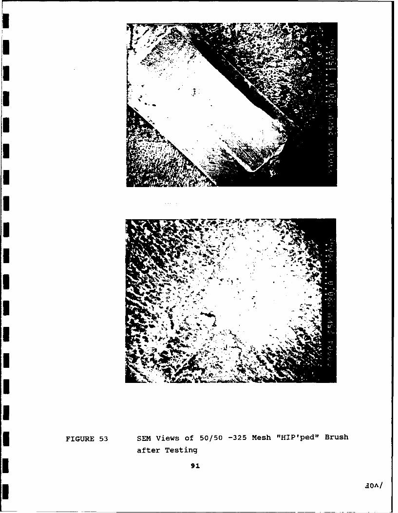
I
II
4-
FIGURE 53 SEM Views of 50/50 -325 Mesh "HIP'ped" Brush
after Testing
I O91
AOA/l
IIII 6. CONCLUSIONS
This program has demonstrated the following!I0 Non-equilibrium compositions of copper lead alloys can be
continuously cast into ingots or gas atomized into powders.
* The powders can be consolidated successfully using both"HIP'ped" and "Shock Compaction Methods."
I The "As Cast" and the "HIP'ped" powders can be readily
machined into engineering components while the "Shock
Compacted" materials proved to be brittle, and little prospect
can be seen for this class of materials without further
studies devoted to the optimization of heat treatment and
compaction parameters to increase the strength and ductility
* of the base material.
The general conclusions from the friction and wear studies are the
I following:
S [a Processing and composition significantly influence the overall
behavior of these alloys.Ia It was clearly established that fine distributions of lead
produced better friction and wear values than coarse
distributions of lead.
Ia "As Cast" alloys showed low friction values but high wear
rates. Clearly this suggests that lead distribution plays a
* major role in the film formation and degradation processes.
* "Shock Compacted" materials have to be post heat-treated to
achieve ductility and reduce residual stresses induced by
processing.
92
a The ability of lead to form a tenacious form of lead oxide
during consolidation is probably responsible for the high
friction values observed in the "HIP'ped" and "Shock
Compacted" conditions.
The general conclusions from the testing of tribological components
in vacuum suggest that:
In the case of bearing cages, the best performance was
provided by the 90/10 "HIP'ped" -325 mesh material, which far
outperformed the standard lead bronze cages over the first one
million revolutions, in that the torque noise of the running
bearings was greatly reduced. Unfortunately beyond this point
the performance suffered from unacceptable short-lived torque
noise spikes as material was transferred to the bearing races
from the cages.
* In the case of gears, the best performance was provided by the
pair of gears manufactured from the 90/10 "HIP'ped" -325
material, however the wear rate was a factor of ten cr more
higher than other polymeric gears under similar conditions.
* In the case of bushings, the best performance was provided in
the 50/50 alloy constituents. Long endurance at steady torque
levels was recorded. The performance is very similar in terms
of torque levels to the proprietary material Glacier DU, which
is a sintered material. Commercial opportunities can exist for
the -100+325 mesh material and will be purely dependent on the
manufacturing costs.
* For brushes, the "HIP'ped" materials performed extremely well
and the peak contact resistance remained stable near the mean
levels throughout the test. The mean contact resistance was
similar to that registered in earlier tests at NCT on the
9.1
standard pressed MoS 2 /Cu/Si composite brushes, which also
suffer from far higher peak resistance performance.
7.0. RECOMMENDATIONS FOR FURTHER WORK
This Phase II program has clearly identified several areas of
promise for the application of copper-lead alloys. However,
designers and materials engineers would be able to exploit the full
potential for these alloys if the following areas are addressed in
future work:
0 Process optimization studies will be necessary in the case of
hot isostatic pressing of the copper-lead powders. This will
significantly improve the information available for pressing
components at the correct temperature for each alloy
composition.
* The "Shock Compacted" process demonstrated considerable
promise and exhibited very fine microstructures in these
alloys. However significant work related to post shock
compaction processing to relieve the stresses will be required
prior to fabrication of engineering components.
The testing of tribological components in vacuum has some
areas which are worthy of consideration for further investigation.
These include:
* Brushes are the most worthy of further consideration at this
stage. A market for these powders in terrestrial applications
relating to brush materials in car starter motors and other
similar items, where copper lead powders are currently used is
readily available. The brush industry currently blends
individual copper and lead powders which leads to problems in
homogeneity and environment. If free floating lead can be
tied up as an alloy these powders can be used directly in
brush applications.
94
* In the case of high value added brushes used in spacecraft,
the following program of work would give the rest of the
information required to prove their viability:-
1) Measure friction levels and wear rates both in air and in
vacuum against load and speed, when running against a
silver plated hardened steel counterface.
2) Perform further extended testing on the best materials in
vacuum against silver plated slip rings.
3) Fit a DC motor with sample brushes, and measure the "in-
vacuo" performance characteristics.
Each item of work should be performed sequentially to allow
the best choices to be made at the end of each stage.
* With regard to the bearing cage performance, the "HIP'ped"
material gave precisely the desired performance for the first
period of running. Further work to enhance the "HIP'ping"
parameters, or alternatively looking at different mesh sizes
could lead to prolonging this behavior beyond the current
result.
* The bushing market may be receptive to a new material both for
terrestrial and space environments. Further development
however will be dependent on the relative costs and
performance of the powders versus the current standard
materials.
95
8.0. REFERENCES
1) Lubrication Handbook for the Space Industry - NASA TM 86556,
December 1985.
2) G.R.Smith and C.E.Vest, Lubrication Engineering, p 27, 1971.
3) C.L.Harris and M.G.Warwick, Proceedings I Mech E, Vol.31, p
183, 1969.
4) M.D.Kanakia and M.B.Peterson, Report BFLRF No 213, Fort
Belvoir, July 1987.
5) F.J.Clauss, Solid Lubricants and Self Lubricating Solids,
Academic Press, 1972.6) M.J.Todd and R.H.Bentall, ASLE SP-6, p 148, 1978.
7) P.J. O'Donnell, Proceedings of First European Space Tribology
Symposium, SP 111, p 251, 1975.
8) M.Hansen and K.Anderko, "Constitution of Binary Alloys"
Second Edition, McGraw Hill, New York, pp 347, 1958.9) A.Kamio and S.Oya, Report of the Castings Research
Laboratory, Waseda University, No.19, 1968.
10) J.D.Livingston and H.E.Cline, Transactions of Metallurgical
Society of AIME, Vol.245, p 351, 1969.11) J.P. Pathall and S.N. Tiwari, Wear, Vol 155, pp 37-47, 1992.
12) S.Shah, R.N.Grugel and B.D.Lichter, MetallurgicalTransactions, Vol.19A, p 2677, 1988.
13) A.Bergmann, T.Carlberg, H.Fredriksson and J.Stjerndahl,
Materials Processing in the Reduced Gravity Environment ofSpace, Guy.E.Rindone, Editor, Materials Research Society,
Elsevier, p 579, 1982.
14) A.Bergmann, H.Frederiksson and H.Shahani, Journal of
Materials Science, Vol.23, p 1573, 1988.15) A.C.Sandlin, J.B.Andrews and P.A.Curreri, Metallurgical
Transactions, Vol.19A, p 2665, 1988.
16) J.B.Andrews, A.C.Sandlin and P.A.Curreri, Metallurgical
Transactions, Vol.19A, p 2645, 1988.
17) A.Kamio and S.Oya, Report of the Castings Research
Laboratory, Waseda Universrity, No.20, 1968.
96
18) R.N.Grugel and A.Hellawell, Metallurgical Transactions,
Vol.12A, p 669, 1981.
19) A.Thomas, A.L.Garnham and M.J.Todd, Current Status of LeadLubrication of Ball Bearings, Proceding Second Tribology
Workshop, ESA SP-158, pp.97-103, December 1980,
20) E.W.Roberts and M.J.Todd, Space and Vacuum Tribology, Wear,
136, pp.157-167, (1990).
21) R.A.Rowntree, The Tribology of Gears for Space, Tribology in
Aerospace Institute of Mechanical Engineers Seminar, January
1985.22) A.Poncet, Ultra-High-Vacuum Tests and Experience of a Long-
Life, Heavy-Duty, Oscillating ROd-End Pivot for the Movable
Ferrite Shutters of the CERN Antiproton Accumulator, Proc.
Second Tribology Workshop, ESA SP-158, pp.49-55, December
1980.
23) J.C.Anderson, "The Wear and Electrical Characteristics of some
Dry Lubricated Slip Ring/Brush Contacts," Proceedings of the
Second Tribology Workshop, ESA SP-158, pp.125-132, December
1980.
24) E.W.Roberts, Sliding Electric Contacts in Space: "Observations
on Existing Technology and New Trends in Low-Speed
Applications", Proceedings of the First European Space
Mechanisms and Tribology Symposium, ESA SP-196, pp.3-10,
October 1983.
97


![HIGen HIGeneralInformationandAdjustments 2018 HI1 · $5Children'sTrust,DomesticViolence,andAbuseSpecialAccounts.....(T=Taxpayer,S=Spouse,B=Both) [11] 2018 ExacTax,Inc. HI1 HI1](https://img.pdfslide.net/doc/110x75/5e749bee97352f17b44d7aef/higen-higeneralinformationandadjustments-2018-hi1-5childrenstrustdomesticviolenceandabusespecialaccountsttaxpayersspousebboth.jpg)