Embed Size (px)
Citation preview

Tidal Height Retrieval Using Globally Corrected GPS in the Amundsen Gulf Region of the
Canadian Arctic
Travis Wert, Mapping and Charting Establishment, Department of National Defence (Canada) Peter Dare, Geodetic Research Laboratory, Dept. of Geodesy and Geomatics Engineering, University of New Brunswick
John Hughes Clarke, Ocean Mapping Group, Dept. of Geodesy and Geomatics Engineering, University of New Brunswick
BIOGRAPHIES Travis Wert is a Captain in the Canadian Forces, presently posted to the Mapping and Charting Establishment in Ottawa, Ontario. Travis is currently employed as the 1 (Geo) Troop Commander of the unit’s Geomatics Support Squadron, where he is responsible for the training and overall preparedness of five Geomatics Support Teams for rapid or long term deployment with Canadian Forces anywhere in the world. Travis received a B.Eng. in Civil Engineering from the Royal Military College of Canada in 1996. He successfully defended his M.Sc.E. in Geomatics Engineering from the University of New Brunswick’s Department of Geodesy and Geomatics Engineering in September 2004. Peter Dare is the Chair of the Department of Geodesy and Geomatics Engineering, University of New Brunswick. He obtained a BSc (Hons.) in Land Surveying Sciences from North East London Polytechnic in 1980, a MASc in Civil Engineering from the University of Toronto in 1983 and a Phd in Geodesy from the University of East London in 1996. He joined the University of New Brunswick in 2000 and became the Chair of the Department in 2002. He is a member of the Department’s Geodetic Research Laboratory. John Hughes Clarke is the Chair of the Ocean Mapping Group, Department of Geodesy and Geomatics Engineering, University of New Brunswick. John obtained a BA in Geology from Oxford University in 1983, an MSc in Oceanography from the University of Southampton in 1984, and a PhD in Geological Oceanography from Dalhousie University in 1988. ABSTRACT The recent evolution of global Wide Area Differential GPS (WADGPS) networks has greatly increased the already high level of interest in GPS technologies by thehydrographic community. The aim of this paper is to evaluate one of these WADGPS systems, the C & C Technologies Globally Corrected GPS (GcGPS) C-Nav, as an instrument for tidal height retrieval in the Canadian Arctic. The C-Nav receiver was mounted aboard the Canadian Coast Guard Ship (CCGS) Amundsen for her 14-month over-wintering expedition in the Northwest Passage. C-Nav height data were collected in Franklin Bay, North West Territories, over February to April 2004. Data were collected over a 40-day period to ensure the capture of all significant wavelength tidal effects. As a ‘true’ vertical reference, Knudsen K320 sub-bottom profiling sonar depth data were collected. The 1 Hz C-Nav data were processed and decimated down to 6-minute epochs, thus speeding the filter processing to obtain real-time data latency. Over the course of the research period, the standard deviation of the C-Nav data was 4.3 cm, when compared to the ‘true’ tidal signature given by the K320. This level of positioning is commensurate with International Hydrographic Organization (IHO) Special Order surveys. In addition, the benefits of the C-Nav solution were apparent in capturing the phase lag of the tides due to sea ice effects. Tidal predictions using common software applications such as the Unix based program Xtide, yielded standard deviations of 5.3 cm. INTRODUCTION Hydrographers have, over the last two decades, utilized the benefits of global navigation satellite systems (GNSS) such as the Navstar Global Positioning System (GPS) for horizontal positioning. As GPS technologies and procedures have improved, hydrographers have come to realize the full benefits of new GNSS measurement methods, such as real time kinematic GPS (RTK GPS), in providing accurate, high frequency, vertical positioning solutions for inshore hydrographic surveys. This has reduced the requirement for the hydrographer to base their vertical solutions on the measurement and collection of

raw tidal data which, when coupled with predictions for propagated amplitude and phase in coastal regions, would become the uneven datum upon which they would measure their soundings. An offshoot of this advantage is the possible ability to collect these tidal data using GPS heights as an observable for water level estimation in any hydrographic, oceanographic, or similar scenario. RTK is not a suitable choice for offshore or otherwise remote operations, due to the inherent baseline limitations. Recently, globally augmented technologies have come to the forefront in this question. This paper evaluates one of these new globally augmented systems, the C & C Technologies C-Nav Globally Corrected GPS (GcGPS) for tidal height retrieval in an area of small tidal influence, the Amundsen Gulf of the Canadian Arctic. The evaluation utilizes temporally efficient processing techniques in an attempt to maximize the value of the observables while minimizing both processing complexity and time. C-NAV GLOBALLY CORRECTED GPS (GcGPS) In partnership with NavCom Technologies Inc., a subsidiary of John Deere and Co., C & C Technologies has developed a Satellite Based Augmentation System (SBAS). This technology is designed to provide decimetre level positioning worldwide, for the hydrographic, offshore oil, construction, and geodetic survey industries [Roscoe Hudson and Sharp, 2001]. This section of the paper contains a brief explanation of the service, its evolution, global infrastructure, user equipment, and published specifications. Additional papers describing the service can be found on the C & C Technologies website, www.cctechnol.com. C & C Technologies’ GcGPS is essentially a marine version of NavCom Technology Inc.’s StarFire™. StarFire™ was developed by NavCom and Ag Management Systems (AMS), both subsidiaries of John Deere and Company, and is operated by NavCom Technology Inc. The system is based on dual frequency architecture and therefore only corrects for satellite orbit and clock errors. Tropospheric effects are modeled using the UNB3 model while multipath is reduced using advanced carrier smoothing techniques. StarFire™, in its original form, consisted of several regional, independent WADGPS networks around the world. NavCom’s Wide Area Correction Transform (WCT) technology was the algorithm put in place to support the international agricultural operations of John Deere. In terms of infrastructure, little has changed between early versions of StarFire and the current evolution although, as we will see later, there has been a much larger reference network component added to the
system. The current status of the system can be decomposed into seven distinct components:
- Reference stations in the WCT network
number 20, with 8 in the USA, 5 in Australia, 4 in Europe, and 3 in South America. A full set of observables (C/A and P code pseudoranges, L1 and L2 phase pseudoranges, plus a record of the broadcast ephemeris) to each satellite in view is sent from each reference station to terrestrial Network Processing Hubs.
- Network Processing Hubs (NPH) take the
smoothed, refraction corrected pseudoranges and normalize them with respect to clock offsets, and further augment these with site modeled tropospheric effects. These ranges are then amalgamated in a weighted average to produce a single, wide area correction for each satellite in the constellation.
- Land Earth Stations (LES) are satellite
uplink facilities that upload the correction messages to the geostationary satellites.
- Communication links are required to
transmit data from each reference station to the processing hubs, and again from the hubs to the LES. The data are sent via an assortment of transmissions, ensuring that there is constant transmission between any of the separate components.
- Geostationary satellites receive the
corrections from the LES and transmit them to users via L-Band satellite communication frequencies. Currently, StarFire™ transmits via Inmarsat, with coverage between 76˚ N and 76˚ S latitude.
- Monitor receivers are distributed throughout
the global footprint to continually observe the operation and health of the system.
- StarFire™ user equipment combines the
broadcast corrections with the raw, dual frequency GPS observables through a Kalman filter, giving the precise position solution.
Two important advances were made with WCT
to eliminate weaknesses of WADGPS: first a dual frequency system was chosen to eliminate ionospheric effects and, secondly, extended carrier smoothing techniques were developed, thus eliminating multipath effects at the receiver, thereby negating the two largest

sources of error in WADGPS solutions. The dual frequency, refraction corrected pseudoranges allow for a differential correction free from the spatial de-correlation existent in ionospheric delays present when using single frequency observables, thus making the initial StarFire WCT corrections valid over the continental network footprints. This central processing allows for upgrades or changes to the processing algorithms to be carried out transparent to users, while the single correction over the continental footprint requires much less bandwidth, thereby lowering cost of the service considerably. The one-sigma accuracy expected from WCT StarFire™ is 23 cm horizontal and 32 cm vertical [Hatch et al., 2003]. As with WAAS, the performance of the WCT correction is dependent on the receiver’s location with respect to the reference network. WCT correction performance degrades increasingly as the receiver moves away from the respective continental footprints. Principally, this is due to the inaccuracies in broadcast satellite orbits limiting the differential solution to an extent which makes it inoperable over a global area. Using a state-space approach, satellite errors can be estimated and corrected in the satellite space, irrespective of the user receiver position. Employing this theory, the improved evolution of the system uses satellite clock and orbit error estimates from the Jet Propulsion Laboratory’s (JPL) Real Time Gipsy (RTG) software to provide global sub-decimetre accuracy making use of an enlarged reference network. The California Institute of Technology’s JPL has developed a precise GPS positioning software package, GIPSY-OASIS II. Recently, improvements to the initial GIPSY algorithms were made, enabling the software to perform in real-time, culminating in the RTG correction software. RTG corrects for two significant error sources [Gregorius, 1996]:
- Clock corrections for each GPS satellite. These are computed every few seconds, optimized for dual frequency users.
- Orbit corrections for each GPS satellite.
These are computed every few minutes. A global GPS reference network, known as the Global GPS Network (GGN), was established and is maintained by NASA and JPL. This network consists of over 50 stations, many of which have to date been linked to JPL’s RTG algorithm. These sites maximize the observability of the GPS constellation and are therefore concentrated in the mid latitudes. Again, global representation is not a requirement of the network as the corrections computed are rooted in the satellite state-space, not on the earth based receivers, or their local effects.
Figure 1: C-Nav Global Corrected GPS (GcGPS) Network [from C & C Technologies, 2004a]
Figure 1 shows the C-Nav representation of the StarFire™ Network, combining the WCT network with many of the GGN stations. The original John Deere WCT reference sites are shown in green, while the JPL/NASA GGN sites are shown in red. The RTG algorithms use the full set of observables from each GGN and WCT station. The WCT corrections are still offered as a backup set of corrections in the areas where WCT is available. The blue symbols in Figure 1 represent the processing and communication components, such as the NPHs, the satellite uplink LEHs, and the GPS master clock located at the US Naval Observatory. The footprint and nadir position of each Inmarsat communication satellite are also visible. C-NAV USER EQUIPMENT The C-Nav user equipment is tasked with receiving the broadcast corrections, applying these values to its own dual frequency, refraction corrected observables, and performing the position and navigation solution. To carry this out, the user equipment consists of:
- A tri-band antennae; to receive GPS L1 and L2, as well as the L-band Inmarsat signal.
- An Inmarsat signal receiver, which acquires,
tracks, and demodulates the correction data. - A high performance dual-frequency GPS
engine, the NavCom NCT2000D. Illustrations of the three separate components as well as a picture of the completely integrated housing are shown in

Figure 2. A hardhat is placed next to the C-Nav unit to give scale.
Figure 2: C-Nav antennae/receiver [from C & C Technologies, 2003]
The GPS receiver has 10 dual frequency channels for tracking GPS satellite signals, and two dedicated for reception of the SBAS signals. Multipath mitigation and tropospheric corrections are accomplished using techniques which further enhance the 10 Hz or 1 Hz solution. Although not a critical component of the system, a display unit can be used for receiver settings and firmware upgrades, or they can be input via serial communications from laptop computer. C-Nav’s specified 1σ accuracies, as published in the product brochure [C & C Technologies, 2004b] are 10 cm horizontal, and less than 30 cm vertical. This level of accuracy achieves International Hydrographic Organization (IHO) First Order positioning standards as described in the next section. HYDROGRAPHIC USE OF GPS POSITIONING An accurate real-time DGPS solution allows the hydrographer to avoid the whole issue of tides. To the hydrographer, tides are a nuisance parameter and are not required to be explicitly solved for. With the movement of the IHO to GPS referenced tide gauges, there is now a much clearer understanding of WGS84 to chart datum transfers [Wells, 2003]. These separation values are currently being refined worldwide, producing local separation models similar to GPS ellipsoid-geoid height transfers. Using GPS at a vertical positioning accuracy commensurate with the required heighting standard allows the hydrographer to reference their depths directly to the GPS ellipsoid, thereby completely avoiding the
tidal reduction process. Transfer of these soundings to chart datum then only requires the application of the one- dimensional shift as described above. This shift, however, can be cumbersome, and a clear understanding of the vertical datum is required. In areas of marine traffic, benchmarks are positioned near docks and jetties that are measured with respect to chart datum. There are current efforts to annotate each of these benchmarks with GPS ellipsoid elevations as well. Once this is complete, the practice of mapping GPS heights to chart datum will be a simple scalar addition. Although there are numerous country-defined designations of allowable tolerances for vertical control during hydrographic surveys, the IHO has developed a set of standards that have been adopted by many member countries. Table 1 gives the position tolerances as a function of survey order. The depth accuracies include all errors in positioning and propagation. We can roughly equate the fixed ‘a’ value for each order to the allowable positioning error.
Table 1: IHO positioning standards [from International Hydrographic Organization, 1998]
Order Special First Second Third Area Example
Harbours, berths, critical
channels
Harbour approaches,
depths to 100m
Areas not yet
described up to 200m depth
Offshore areas not classified special, 1st
or 2nd order
Horizontal Accuracy, (2σ)
2m 5m + 5% depth
20m + 5% 150m + 5%
Depth Accuracy, (2σ)
a = 0.25m b = 0.0075
a = 0.5m b = 0.013
a = 1.0m B = 0.023
Same as 2nd Order
Where depth accuracy is given as +/- √(a2 + (b*depth)2) Using commonly relied upon techniques such as RTK-GPS, centimetre level accuracies are attainable up to baselines of 20 km length from the base station. This is sufficient for all orders of survey. In addition to the removal of tidal ‘noise’, GPS also removes the long wavelength effects of dynamic draft. However, for baselines in excess of 20 km length, the RTK-GPS solution becomes less reliable. For surveys far offshore, the requirement for a base-station simply cannot be met. In this instance, a different method must be used. For GcGPS positioning, or any other system to merit use hydrographically, the vertical solution must be of an order which would satisfy the IHO vertical standards shown in Table 1. Figure 3 illustrates the technique, explaining the differences between this method and traditional hydrographic survey height calculations.

Figure 3: Vertical positioning with GPS
In the case of positioning with GPS, only one measurement is required: GPS height with respect to the ellipsoid, HAE. Note that this value can be negative as shown in Figure 3. This case measures in essence a GPS height below the ellipsoid. This is generally the case in the province of New Brunswick in eastern Canada, where Mean Sea Level (MSL), or its representative geo-potential surface, the geoid, is ~25 m below the WGS84 ellipsoid. The GPS antenna will be surveyed to the vessel coordinate frame once installed, giving the height value, H. This measured height value never changes, though we will see later its orientation can. For each survey area, datum shift values (Diff in Figure 3) between the WGS84 ellipsoid and chart datum will be previously established, as already mentioned. Therefore, every sounding can be automatically converted into a chart sounding as per Equation 1.
DiffHHAEDC SS −−−= )( (1) Other motions that may bias these GPS heights affect survey vessels. Heave sensors are a requirement for short wavelength vertical motions but they also have another important role. Because the GPS antenna is positioned well away from the centre of gravity of the vessel, (normally the centre of the vessel coordinate frame), there is a large lever arm that will reduce the GPS antenna’s HAE in cases of pitch and roll. Using heave sensor data, these rotations must be applied to the lever arm in order to eliminate the vertical biases caused by these motions. EXPERIMENTAL DESIGN There have been numerous studies into the performance of globally augmented systems in recent years. The C-Nav itself has been the subject of multiple studies such as Bisnath et al. [2003], Dixon [2003], Chance et al. [2003] and Osbourne and King [2004]. While all of these have
undertaken a performance evaluation of the service, only Osbourne and King [2004] employed the C-Nav receiver in a dynamic environment, with comparisons of vertical performance with respect to tides. The aim of this research was to evaluate C-Nav’s performance in an area of micro-tidal influence, non-optimal GPS coverage, using expeditious processing techniques to further improve the vertical solution in order to attain IHO Special Order standards. The research occurred in two phases: preliminary investigation took place in the summer and fall of 2003 at the University of New Brunswick (UNB), while the field research took place from February to April 2004 aboard the Canadian Coast Guard Ship (CCGS) Amundsen (see Figure 4).
Figure 4: Author Travis Wert in front of CCGS Amundsen
The primary purpose of the preliminary investigation was to conduct independent checks on previously published C-Nav results while concurrently developing algorithms for both data handling and processing. As mentioned, this occurred at UNB with two separate C-Nav units; one mounted statically atop UNB’s Geodetic Research Laboratory in UNB’s Gillin Hall (see Figure 5), and the other mounted aboard the UNB Ocean Mapping Group (OMG) survey launch, CSL Heron (see Figure 6).

Figure 5: C-Nav mounted on Gillin Hall roof
Figure 6: CSL Heron During static evaluations, several decisions were made with regards to sampling. In regular hydrographic operations, a 1 pulse per second (pps) or 1 Hz data frequency is normally used. This was chosen as the C-Nav output frequency. NMEA GPGGA strings were used as the standard output, again mimicking hydrographic operations data flow. As this research was designed to achieve the greatest benefit from the C-Nav system while minimizing cumbersome processing techniques, the use of RINEX data in higher grade processing formats was not employed. In traditional tidal sampling, i.e. with standard float gauges, a 6-minute sampling interval is employed. It was therefore important to limit smoothing effects so that there would be no filter effects entering this period. The NMEA strings were parsed using awk scripts
and ellipsoidal heights were smoothed using a 1-minute moving average filter, and then decimated to 6 minute intervals. These smoothed heights were then passed through a low-pass filter, set to reduce the effects of wavelengths less than 6 hours. The 6-hour cut-off frequency was chosen to fully mitigate the effects of short wavelength effects while fully preserving the desired signals in the 12 and 24-hour period ranges. PRELIMINARY RESULTS Figure 7 shows the results of the filtering over a 7 day period in winter 2003 for the UNB static investigation. The variability in the heights seems excessive before realizing that the earth tides in the Fredericton region can be as great as 25 cm. There is an obvious diurnal nature to the oscillations. In addition, there is an unexplained overrun at the peak of each tidal oscillation that exceeds 25 cm in some instances. The residuals between the filtered signal and the raw data are shown in Figure 8.
Figure 7: Initial static evaluation
Figure 8: 7-Day static residuals
The mean of the residuals is -4.7 mm, with a standard deviation of 9.2 cm: this bias is statistically insignificant. There are, however, short period trends present in the residuals. SHIPPAGAN SURVEY DATA During the summer of 2003, the UNB OMG took part in a survey near Shippagan, New Brunswick, Canada. Figure 6 shows the survey vessel CSL Heron outfitted with the C-Nav receiver. During the survey, the horizontal position output from the C-Nav was used as the primary positioning, while the vertical solution was determined through the use of a conventional tide gauge located at the dock in Shippagan Harbour. The survey work was only done during the day so there was no long term, continuous, sample taken. The NMEA data were extracted from the Simrad EM3000 data strings, producing the plot seen in Figure 8. For the most part, the C-Nav height solution is very close to true tides, though there is some evidence of overrun at the tidal peaks, possibly due by the vessel moving into a different tidal regime.
Figure 8: Shippagan tidal comparisons
FIELD RESEARCH PLAN The Canadian Arctic poses numerous challenges to GPS positioning. Poor geometry and increased ionospheric and tropospheric refraction can greatly reduce system performance. For this reason, C-Nav evaluation aboard the CCGS Amundsen during her Canadian Arctic Shelf Exchange Study (CASES) over-wintering expedition in the Amundsen Gulf was expected to be a rigorous test. CASES is a Canadian Government scientific research initiative that includes researchers in varying fields from numerous countries; including Poland, Germany, Switzerland, Russia, and the United States. As part of the funding, the original CCGS Sir John Franklin was refitted for scientific purposes and renamed the CCGS
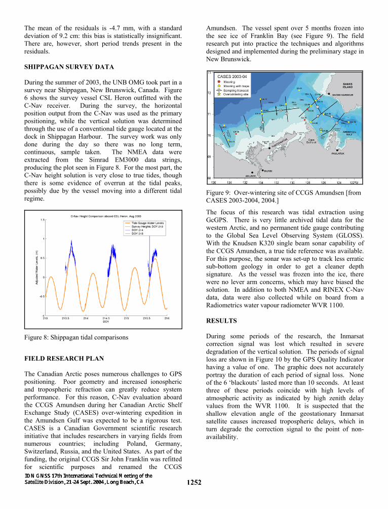
Amundsen. The vessel spent over 5 months frozen into the see ice of Franklin Bay (see Figure 9). The field research put into practice the techniques and algorithms designed and implemented during the preliminary stage in New Brunswick.
Figure 9: Over-wintering site of CCGS Amundsen [from CASES 2003-2004, 2004.]
The focus of this research was tidal extraction using GcGPS. There is very little archived tidal data for the western Arctic, and no permanent tide gauge contributing to the Global Sea Level Observing System (GLOSS). With the Knudsen K320 single beam sonar capability of the CCGS Amundsen, a true tide reference was available. For this purpose, the sonar was set-up to track less erratic sub-bottom geology in order to get a cleaner depth signature. As the vessel was frozen into the ice, there were no lever arm concerns, which may have biased the solution. In addition to both NMEA and RINEX C-Nav data, data were also collected while on board from a Radiometrics water vapour radiometer WVR 1100. RESULTS During some periods of the research, the Inmarsat correction signal was lost which resulted in severe degradation of the vertical solution. The periods of signal loss are shown in Figure 10 by the GPS Quality Indicator having a value of one. The graphic does not accurately portray the duration of each period of signal loss. None of the 6 ‘blackouts’ lasted more than 10 seconds. At least three of these periods coincide with high levels of atmospheric activity as indicated by high zenith delay values from the WVR 1100. It is suspected that the shallow elevation angle of the geostationary Inmarsat satellite causes increased tropospheric delays, which in turn degrade the correction signal to the point of non-availability.

Figure 10: Raw observations
Figures 11 through 13 illustrate selectively chosen poor performance of the filter aided C-Nav solution during the period Day-of-Year (DOY) 60-90. It should be noted that the standard deviation of the K320 filtered heights is less than 3 cm, likely caused by bottom scattering effects. Figure 11 depicts one of the rare periods where there appeared to be a divergence between the two filtered signals that appeared to be dependent on phase – there is no explanation for this effect at the moment.
Figure 11: DOY 83-84
During DOY 86, increased atmospheric activity likely caused the spike in elevation of nearly 1.5 m shown in Figure 12. It was a short wavelength event and was removed by the filter.
Figure 12: DOY 85-87
Figure 13 illustrates the worst case of divergence between the filtered GPS and the K320 heights during the research period. Here, the separation grows and shrinks over 5 hours, reaching a maximum residual of nearly 15 cm. Although there was no Inmarsat loss during this period, extreme tropospheric zenith delays were present, as observed with the WVR 1100 and plotted in Figure 10, and at the reduced GPS satellite elevation angles characteristic of Arctic operations, this would be sufficient to contaminate the vertical solution.
Figure 13: DOY 89-90
Throughout the entire sampling period, the standard deviation of the C-Nav solution compared to the K320 tidal signature was 4.3 cm. This is more than sufficient for IHO Special Order surveys. Normally, in areas where a tide gauge is neither close by nor where installation is impractical, the hydrographer is reliant upon tidal prediction software to reduce soundings to chart datum. In moderate latitudes where there exists a wealth of historical tidal data among numerous sites of each major ocean basin, this does not present significant problems. In the Arctic however, there is not a great deal

of archived data, and environmental considerations make temporary gauge installations all but impossible. Frequently, tidal predictions are less than ideal but are the only data available. Figure 14 demonstrates the result of both C-Nav and XTide predictions as compared to the K320 data over a four day period. During this time, the standard deviation of the XTide prediction compared to the K320 tides was 5.3 cm, greater than the 4.3 cm value for the C-Nav.
Figure 14: Comparison of measured and predicted tides
CONCLUSION AND FUTURE STUDY The intent of this paper was to determine if the C & C Technologies C-Nav GcGPS receiver was capable of extracting the 40 cm tidal signature in the Amundsen Gulf of Canada’s Arctic. The research methodology was designed to carry out the experiment under the harshest conditions of the Arctic winter. The findings are summarized as follows:
- With a standard deviation of 4.3 cm, C-Nav accurately detected the tides to a level commensurate with IHO Special Order surveys.
- During Arctic operations, increased
meteorological activity can make the low elevation Inmarsat signal susceptible to corruption and ultimately signal loss.
- Increased tropospheric delays manifest
themselves as degraded elevation performance.
- The C-Nav receiver module is capable of
operating in environmental temperatures below -50 ºC.
Further study should be expanded to possibly include trial runs underway over a flat ocean bottom so that an accurate height reference is available. Although no problems with regards to the GPS antenna lever arm are anticipated, seaward trials would solidify this opinion. In keeping the focus of this research to create easy-to-use hydrographic survey operator tools, little attention was paid to the receiver RINEX files. A deeper investigation of the constellation parameters during the research could further enhance the understanding of inherent limitations of both Arctic operations, and hydrographic positioning in general. ACKNOWLEDGMENTS The authors would like to thank C & C Technologies, Inc., specifically Jim Chance, Art Kleiner, and Tim Patro, for guidance and insight regarding the C-Nav equipment. The Canadian Arctic Shelf Exchange Study (CASES) and the Canadian Coast Guard are acknowledged for allowing the opportunity to use the CASES expedition and the CCGS Amundsen as the platform for this research project. REFERENCES Bisnath, S., D. E. Wells, and D. Dodd (2003). “Evaluation of commercial carrier phase-based WADGPS services for marine applications.” Proceedings of the Institute of Navigation GPS/GNSS 2003. Portland, Oregon, U.S.A. C & C Technologies (2003). C-Nav GPS System Operations Manual”. [On-line] October 23 2003. ftp://ftp.cctechnol.com/pub/C-Nav/C-Nav Manual.pdf C & C Technologies (2004a). “C-Nav Global Corrected GPS (GcGPS) Network”. [On-line] September 26 2004. http://www.cctechnol.com/site52.php C & C Technologies (2004b). “C-Nav 2000 RM” [On-line] September 26 2004. http://www.cctechnol.com/uploads/CNav_2000RM.pdf CASES 2003-2004 (2004). [On-line] September 26 2004. http://www.cases.quebec-ocean.ulaval.ca/trip/map2.asp Chance, J., J. Gravely, J. Roscoe-Hudson, A. Kleiner. (2003). Hydro INTERNATIONAL, October. Dixon, K. (2003). “Decimetre accuracy – without base stations.” Geomatics World, Vol.11, No. 4, pp. 32-34. Gregorius, T. (1996). “GIPSY-OASIS II, How It Works.” Department of Geomatics, Technical Report, University of Newcastle upon Tyne, Newcastle upon Tyne, U.K.

Hatch, R., T. Sharpre, and P. Galyean. (2001). “StarFire: A Global High Accuracy Differential GPS System”. [On-line] September 2003. http://www.cctechnol.com/papers/StarFireAGlobalHighAccuracySystem.pdf International Hydrographic Organization (1998) “IHO Standards for Hydrographic Surveys”. International Hydrographic Organization, Special Publication No. 44, 4th edition, April, pp 23. Osbourne, A., and L. K. Wing. (2004). “GcGPS for Offshore Tide Measurement.” Geomatics World. Vol. 12, No. 3, pp. 22-23. Roscoe Hudson, J., and T. Sharp (2001) “Globally Corrected GPS (GcGPS): C-Nav GPS System.” Proceedings of the Dynamic Positioning Conference, Houston, Texas, U.S.A. Wells, D.E. (2003). Personal communication. Department of Geodesy and Geomatics Engineering, University of New Brunswick, Fredericton, New Brunswick, Canada.