Embed Size (px)
Citation preview

8/7/2019 timer fuction
http://slidepdf.com/reader/full/timer-fuction 1/16
1
AVR130: Setup and Use the AVR® Timers
Features Description of Timer/Counter Events
• Timer/Counter Event Notification
• Clock Options
• Example Code for Timer0
– Overflow Interrupt
• Example Code for Timer1
– Input Capture Interrupt
• Example Code for Timer2
– Asynchronous Operation
– Compare Match Interrupt• PWM Basics
• Example Code for PWM Operation of Timer2
Introduction
This application note describes how to use the different timers of the AVR. The
AT90S8535 is used as an example. The intention of this document is to give a general
overview of the timers, show their possibilities and explain how to configure them. The
code examples will make this clearer and can be used as guidance for other
applications.
Starting from a general overview of the timers, several examples will show how the
timers work and how they are configured. Experienced users can start directly with the
section “Setting Up the Timers” on page 7. The last section is a short description of
the PWM mode.
Additional information can be found in the data sheets and in application notes where
the timers are used.
General Description
In principle, a timer is a simple counter. Its advantage is that the input clock and oper-
ation of the timer is independent of the program execution. The deterministic clock
makes it possible to measure time by counting the elapsed cycles and take the input
frequency of the timer into account.
Why Different TimersThe answer is quite simple: To have the r ight timer for the right application and to have
enough resources to do this.
Generally, the 90S- and megaAVRs have two 8-bit and one 16-bit timer. A timer with
16-bit resolution is certainly more flexible to use than one with 8-bit resolution. How-
ever, the saying “bigger is better” does not necessarily apply to the microcontroller
world. For many applications, it is sufficient to have 8-bit resolution. Using a higher
resolution means a larger program overhead, which costs processing time and should
be avoided in speed optimized code. It also means higher device cost.
8-bit
RISC
Microcontoller
Application
Note
Rev. 2505A–AVR–02/02

8/7/2019 timer fuction
http://slidepdf.com/reader/full/timer-fuction 2/16
2 AVR1302505A–AVR–02/0
Because of the flexibility of the AVR timers, they can be used for different purposes. The
number of timers determines the amount of independent configurations. In the following
the different configuration options will be described more closely.
Timer Events The timer of the AVR can be specified to monitor several events. Status flags in the
TIMSK register show if an event has occurred. The AT90S8535 can be configured to
monitor up to three events per timer.
Timer Overflow A timer overflow means that the counter has counted up to its maximum value and is
reset to zero in the next timer clock cycle. The resolution of the timer determines the
maximum value of that timer. There are two timers with 8-bit resolution and one timer
with 16-bit resolution on the AT90S8535. The maximum value a timer can count to can
be calculated by Equation 1. Res is here the resolution in bits.
The timer overflow event causes the Timer Overflow Flag (TOVx) to be set in the Timer
Interrupt Flag Register (TIFR).
Compare Match In cases where it is not sufficient to monitor a timer overflow, the compare match inter-
rupt can be used. The Output Compare Register (OCRx) can be loaded with a value
[0 .. MaxVal] which the timer will be checked against every timer cycle. When the time
reaches the compare value, the corresponding Output Compare Flag (OCFx) in the
TIFR register is set. The Timer can be configured to clear the count register to “0” on a
compare match.
Related output pins can be configured to be set, cleared or toggled automatically on a
compare match. This feature is very useful to generate square wave signals of differen
frequencies. It offers a wide range of possibilities which makes it possible to implement
a DAC. The PWM mode is a special mode which is even better suited for wave genera-
tion. See the “PWM Basics” on page 14, the data book or [3] for details.
Input Capture The AVR has an input pin to trigger the input capture event. A signal change at this pin
causes the timer value to be read and saved in the Input Capture Register (ICRx). At the
same time the Input Capture Flag (ICFx) in the TIFR will be set. This is useful to mea
sure the width of external pulses.
Timer Event Notification The timer operates independently of the program execution. For each timer event there
is a corresponding status flag in the Timer Interrupt Flag Register (TIFR). The occur-
rence of timer events require a notification of the processor to trigger the execution o
corresponding actions. This is done by setting the status flag of the event which
occurred.
There are three different ways to monitor timer events and react on them:1. Constantly polling of status flags – interrupt flags and execution of corresponding
code.
2. Break of program flow and execution of Interrupt Service Routines (ISR).
3. Changing the level of output pins automatically.
Polling of Interrupt Flags This method makes use of the fact that the processor marks the timer events by setting
the corresponding interrupt flags. The main program can frequently check the status o
these flags to see if one of these events occurred. This requires some program over
MaxVal 2 Re s 1–= 1( )
8/7/2019 timer fuction
http://slidepdf.com/reader/full/timer-fuction 3/16
3
AVR130
2505A–AVR–02/02
head, which will cost additional processing time. The advantage of this solution is the
very short response time when tight loops are used.
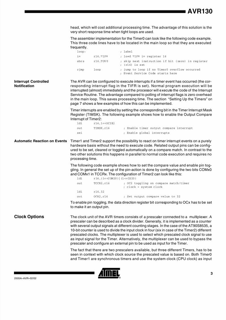
The assembler implementation for the Timer0 can look like the following code example
This three code lines have to be located in the main loop so that they are executed
frequently.loop: ; label
in r16,TIFR ; load TIFR in register 16
sbrs r16,TOV0 ; skip next instruction if bit (zero) in register; (r16) is set
rjmp loop ; jump to loop if no Timer0 overflow occurred
; Event Service Code starts here
Interrupt Controlled
Notification
The AVR can be configured to execute interrupts if a timer event has occurred (the cor-
responding interrupt flag in the TIFR is set). Normal program execution will be
interrupted (almost) immediately and the processor will e xecute the code of the Interrup
Service Routine. The advantage compared to polling of interrupt flags is zero overhead
in the main loop. This saves processing time. The section “Setting Up the Timers” on
page 7 shows a few examples of how this can be implemented.
Timer interrupts are enabled by setting the corresponding bit in the Timer Interrupt Mask
Register (TIMSK). The following example shows how to enable the Output Compare
Interrupt of Timer2:ldi r16,1<<OCIE2
out TIMSK,r16 ; Enable timer output compare interrupt
sei ; Enable global interrupts
Automatic Reaction on Events Timer1 and Timer2 support the possibility to react on timer interrupt events on a purely
hardware basis without the need to execute code. Related output pins can be config-
ured to be set, cleared or toggled automatically on a compare match. In contrast to the
two other solutions this happens in parallel to normal code execution and requires no
processing time.
The following code example shows how to set the compare value and enable pin tog
gling. In general the set up of the pin-action is done by configuring the two bits COMx0
and COMx1 in TCCRx. The configuration of Timer2 can look like this:ldi r16,(1<<COM20)|(1<<CS20)
out TCCR2,r16 ; OC2 toggling on compare match/timer
; clock = system clock
ldi r16,32
out OCR2,r16 ; Set output compare value to 32
To enable pin toggling, the data direction register bit corresponding to OCx has to be se
to make it an output pin.
Clock Options The clock unit of the AVR timers consists of a prescaler connected to a multiplexer. A
prescaler can be described as a clock divider. Generally, it is implemented as a counte
with several output signals at different counting stages. In the case of the AT90S8535, a
10-bit counter is used to divide the input clock in four (six in case of the Timer2) different
prescaled clocks. The multiplexer is used to select which prescaled clock signal to use
as input signal for the Timer. Alternatively, the multiplexer can be used to bypass the
prescaler and configure an external pin to be used as input for the Timer.
The fact that there are two prescalers available, but three different Timers, has to be
seen in context with which clock source the prescaled value is based on. Both Timer0
and Timer1 are synchronous timers and use the system clock (CPU clock) as inpu

8/7/2019 timer fuction
http://slidepdf.com/reader/full/timer-fuction 4/16
4 AVR1302505A–AVR–02/0
source. In this case there is no limitation if both use the same prescaler (as long as each
timer can be configured separately). However, the asynchronous clocked Timer2 needs
its own prescaler to be independent of the system clock.
Figure 1 shows the prescaling and the configuration unit. The data sheets contain more
detailed drawings showing all prescalers and multiplexers. An overview of the possible
clock settings is given in Table 1. In the following sections these settings will be
described more clearly.Notes: 1. The prescaler is constantly running during operation. In cases where the timer has to
count very accurately it has to be ensured that the prescaler starts counting from
zero. On parts without prescaler reset this has to be done by detecting the prescaler
overflow by software and the initialization of the timer counter TCNTx registe
afterwards.
2. On newer devices with shared prescaler, executing a prescaler reset will affect al
connected timers.
Figure 1. Prescaler
Clocking by System Clock In this case, the system clock is used as input signal for the prescaler. Even if a pres-caled value is chosen instead of the system clock, this clock is based on the system
clock. The timer clock is therefore synchronous to the system clock.
All three timers of the AT90S8535 and most timers on other AVR parts support this
option. The advantage of this is that no additional external circuits are needed. Smal
time frames can be implemented or monitored because of the high frequency of the sys
tem clock.
The timer overflow frequency is a good indication of the size of the time frame a time
covers. Equation 1 shows the correlation between the timer overflow frequency TOV CK
the maximum value (MaxVal) of the timer, the system clock (CK) and the division facto
of the prescaler (PVal).
10-bit T/C Prescaler
TCKx
CSx0CSx1CSx2
PCKx
Tx(0-1)
0
PCKx /8
PCKx /32 (2)
PCKx /64
PCKx /128 (2)
PCKx /256
PCKx /1024
(0-1) only available on Timer 0 and 1(2) only available on Timer 2
x [0..2]

8/7/2019 timer fuction
http://slidepdf.com/reader/full/timer-fuction 5/16
5
AVR130
2505A–AVR–02/02
Assume that the CPU is running with f CPU = 3.69 MHz and the resolution of the timer is 8
bit (MaxVal = 256). A prescale value of 64 will then cause the timer to be clocked with
TCK = 3.69 MHz/64 so that there will be about 225 timer overflows per second. See
Equation 2 for the correct mathematical description:
To get 225 timer overflow events per second means that every 4.4 ms an overflow
occurs. The maximum prescaler value will generate a timer overflow every 71 ms while
the minimum prescaler value generates a timer overflow every 69 µs.
In most cases a different approach will be used to determine the settings. The require-
ments of the application will specify the frequency of the timer overflows. Based on this
and the given clock frequency of the CPU together with the timer resolution the pres
caler settings will be calculated according to Equation 3.
Table 1. Overview of the Clock Settings
TCCRxSynchronous Timer0 &
Timer1 PCK = CK
Synchronous/Asynchronous
Timer2 PCK2 = f (AS2)Bit 2 Bit 1 Bit 0
CSx2 CSx1 CSx0 TCK0,1 TCK2
0 0 0 0 (Timer Stopped) 0 (Timer Stopped)
0 0 1 PCK (System Clock) PCK2 (System Clock/Asynchronous
Clock)
0 1 0 PCK/8 PCK2/8
0 1 1 PCK/64 PCK2/32
1 0 0 PC/256 PCK2/64
1 0 1 PCK/1024 PCK2/128
1 1 0 External Pin Tx falling edge PCK2/256
1 1 1 External Pin Tx rising edge PCK2/1024
TOV CK
f CK
MaxVal --------------------
P CKx PVal ⁄ ( )
MaxVal ------------------------------------
P CKx
PVal MaxVal • ( )-------------------------------------------= = = 2 ( )
TOV CK
f CK
MaxVal --------------------
3.69 MHz 64 ⁄ ( )
256 ----------------------------------------- ~225 = = =
PVal P CK x
TOV MaxVal •( )----------------------------------------------- = 3 ( )
8/7/2019 timer fuction
http://slidepdf.com/reader/full/timer-fuction 6/16
6 AVR1302505A–AVR–02/0
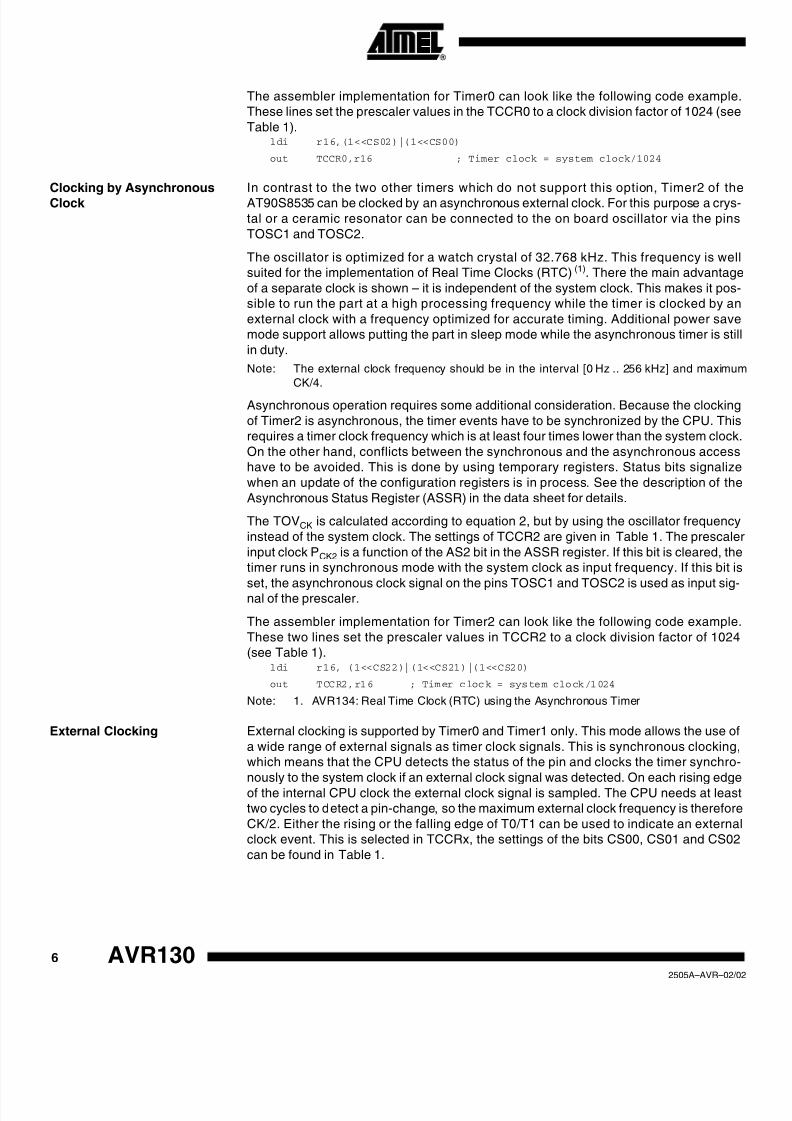
The assembler implementation for Timer0 can look like the following code example
These lines set the prescaler values in the TCCR0 to a clock division factor of 1024 (see
Table 1).ldi r16,(1<<CS02)|(1<<CS00)
out TCCR0,r16 ; Timer clock = system clock/1024
Clocking by Asynchronous
Clock
In contrast to the two other timers which do not support this option, Timer2 of the
AT90S8535 can be clocked by an asynchronous external clock. For this purpose a crys
tal or a ceramic resonator can be connected to the on board oscillator via the pins
TOSC1 and TOSC2.
The oscillator is optimized for a watch crystal of 32.768 kHz. This frequency is wel
suited for the implementation of Real Time Clocks (RTC)(1). There the main advantage
of a separate clock is shown – it is independent of the system clock. This makes it pos
sible to run the part at a high processing frequency while the timer is clocked by an
external clock with a frequency optimized for accurate timing. Additional power save
mode support allows putting the part in sleep mode while the asynchronous timer is stil
in duty.
Note: The external clock frequency should be in the interval [0 Hz .. 256 kHz] and maximum
CK/4.
Asynchronous operation requires some additional consideration. Because the clocking
of Timer2 is asynchronous, the timer events have to be synchronized by the CPU. This
requires a timer clock frequency which is at least four times lower than the system clock
On the other hand, conflicts between the synchronous and the asynchronous access
have to be avoided. This is done by using temporary registers. Status bits signalize
when an update of the configuration registers is in process. See the description of the
Asynchronous Status Register (ASSR) in the data sheet for details.
The TOVCK is calculated according to equation 2, but by using the oscillator frequency
instead of the system clock. The settings of TCCR2 are given in Table 1. The prescale
input clock PCK2 is a function of the AS2 bit in the ASSR register. If this bit is cleared, the
timer runs in synchronous mode with the system clock as input frequency. If this bit is
set, the asynchronous clock signal on the pins TOSC1 and TOSC2 is used as input sig-nal of the prescaler.
The assembler implementation for Timer2 can look like the following code example
These two lines set the prescaler values in TCCR2 to a clock division factor of 1024
(see Table 1).ldi r16, (1<<CS22)|(1<<CS21)|(1<<CS20)
out TCCR2,r16 ; Timer clock = system clock/1024
Note: 1. AVR134: Real Time Clock (RTC) using the Asynchronous Timer
External Clocking External clocking is supported by Timer0 and Timer1 only. This mode allows the use of
a wide range of external signals as timer clock signals. This is synchronous clocking
which means that the CPU detects the status of the pin and clocks the timer synchro-
nously to the system clock if an external clock signal was detected. On each rising edge
of the internal CPU clock the external clock signal is sampled. The CPU needs at leas
two cycles to d etect a pin-change, so the maximum external clock frequency is therefore
CK/2. Either the rising or the falling edge of T0/T1 can be used to indicate an externa
clock event. This is selected in TCCRx, the settings of the bits CS00, CS01 and CS02
can be found in Table 1.

8/7/2019 timer fuction
http://slidepdf.com/reader/full/timer-fuction 7/16
7
AVR130
2505A–AVR–02/02
The assembler implementation for the Timer0 can look like the following code example
These lines set pin T0 as input pin for the timer clock with the rising edge as the active
clock edge (see Table 1).ldi r16,(1<<CS02)|(1<<CS01)|(1<<CS00)
out TCCR0,r16 ; Timer clock = external pin T0, rising edge
Note: It is important ensure that pin T0 is an input pin in the Data Direction Register of Port B
(DDRB). The setting of the direction register will not be overwritten by the timer setup
because it is also allowed to implement a software clocked timer in the AVR. T0 and T1
are inputs by default.
How to Stop the Timer Stopping the timer from counting is simple. A value of zero as prescaler values in the
TCCRx stops the corresponding timer (see Table 1). Remember, however, that the
prescaler is still running.
The assembler implementation for the Timer0 can look like the following code example.clr r16
out TCCR0,r16 ; writing zero to TCCR0 stops Timer0
Note: Other TCCRx may contain configuration bits besides the clock select (CSxx) bits. The
command lines above will clear these bits. This has to avoided if these bits were set
That costs one extra program line, as shown below.
in r16,TCCR0 ; Load current value of TCCR0
andi r16,~((1<<CS02)|(1<<CS01)|(1<<CS00))
; Clear CS02,CS01,CS00
out TCCR0,r16 ; Writing zero to CS02, CS01, and CS00 in TCCR0 stops
; Timer0. The other bits are not affected.
Setting Up the Timers This section shows concrete examples for how to set up the three different timers. The
data sheet and the application notes listed in the “Litterature” section should be read in
addition. Especially when transforming the settings to other parts than the AT90S8535.
Using interrupts is the most common way to react on timer events. The examples which
are described in the following use interrupts.
Independent of the different features of the three timers, they all have two things in common. The timer has to be started by selecting the clock source, and if interrupts are used
they have to be enabled.
Shared Registers If the same registers are used in the interrupt service routines as in the main code, these
registers have to be saved at the beginning of the ISR and restored at the end of the
ISR. If not all 32 registers are needed in the application, the save and restore operations
can be avoided by using separate registers in the main code and the ISR.
It is also very important to remember to store the Status Register (SREG), as this is no
automatically done by the interrupt h andler.
Note: The C compiler handles this automatically, while it has to be done manually by using fo
instance push and pop instructions if assembly language is used.
8-bit Timer0 The 8-bit Timer0 is a synchronous Timer. This means that it is clocked by the system
clock, a prescaled system clock or an external clock which is synchronized with the sys-
tem clock (see section “Clock Options” on page 3 for details about this). This timer is the
least complex of the three. Only a few settings have to be made to get it running.
8/7/2019 timer fuction
http://slidepdf.com/reader/full/timer-fuction 8/16
8 AVR1302505A–AVR–02/0
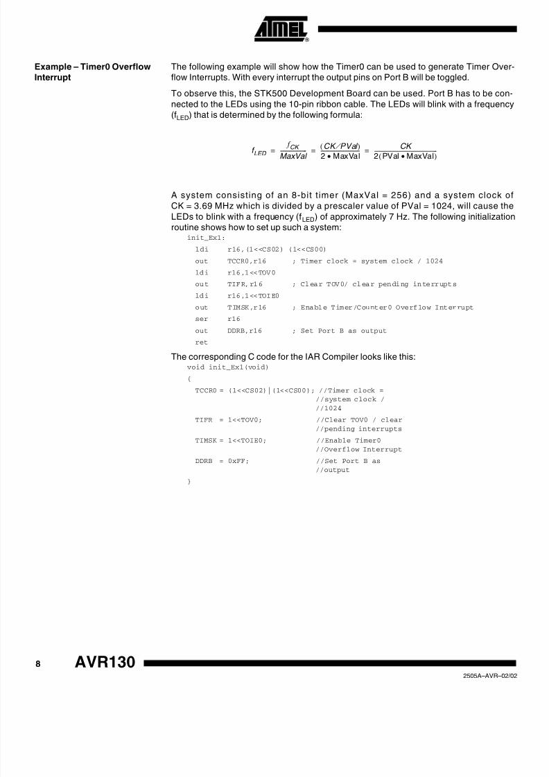
Example – Timer0 Overflow
Interrupt
The following example will show how the Timer0 can be used to generate Timer Over
flow Interrupts. With every interrupt the output pins on Port B will be toggled.
To observe this, the STK500 Development Board can be used. Port B has to be con-
nected to the LEDs using the 10-pin ribbon cable. The LEDs will blink with a frequency
(fLED) that is determined by the following formula:
A system consisting of an 8-bit t imer (MaxVal = 256) and a system clock of
CK = 3.69 MHz which is divided by a prescaler value of PVal = 1024, will cause the
LEDs to blink with a frequency (fLED) of approximately 7 Hz. The following initialization
routine shows how to set up such a system:init_Ex1:
ldi r16,(1<<CS02)|(1<<CS00)
out TCCR0,r16 ; Timer clock = system clock / 1024
ldi r16,1<<TOV0out TIFR,r16 ; Clear TOV0/ clear pending interrupts
ldi r16,1<<TOIE0
out TIMSK,r16 ; Enable Timer/Counter0 Overflow Interrupt
ser r16
out DDRB,r16 ; Set Port B as output
ret
The corresponding C code for the IAR Compiler looks like this:void init_Ex1(void)
{
TCCR0 = (1<<CS02)|(1<<CS00); //Timer clock =//system clock /
//1024TIFR = 1<<TOV0; //Clear TOV0 / clear
//pending interrupts
TIMSK = 1<<TOIE0; //Enable Timer0
//Overflow Interrupt
DDRB = 0xFF; //Set Port B as
//output
}
f LED
f CK
MaxVal --------------------
CK PVal ⁄ ( )
2 MaxVal•-----------------------------
CK
2 PVal MaxVal•( )-----------------------------------------------= = =

8/7/2019 timer fuction
http://slidepdf.com/reader/full/timer-fuction 9/16
9
AVR130
2505A–AVR–02/02
In the next step, the interrupt service routine has to be implemented. This routine will be
executed with every timer overflow. Its purpose in this example is to toggle the bits of
the Port B (the LEDs).ISR_TOV0:
push r16
in r16,SREG
push r16in r16,PORTB ; Read Port B
com r16 ; Invert bits of r16 register
out PORTB,r16 ; Write Port B
pop r16
out SREG,r16
pop r16
reti
The corresponding C code for the IAR Compiler looks like this:void interrupt [TIMER0_OVF0_vect] ISR_TOV0 (void)
{
PORTB = ~PORTB; // Toggle pins on Port B
}
16-bit Timer1 The 16-bit timer1 is a synchronous timer. This means that it is clocked by the system
clock, a prescaled system clock or an external clock which is synchronized with the sys-
tem clock. To ensure that the 16-bit registers of the Timer1 are written and read
simultaneously, a temporary register (Temp) is used. This makes it necessary to access
these registers in a specific order. Please see the application note “AVR072: Accessing
16-bit I/O Registers” and the data book for details. The correct way to access the regis-
ters is shown in Table 2.
According to this, a read operation of a 16-bit register can look like this:in r16,TCNT1L
in r17,TCNT1H
A write operation to this register has to access the registers in the opposite order:out TCNT1H,r17
out TCNT1L,r16
The C Compiler automatically handles 16-bit I/O read and write operations in the correc
order.
Table 2. Accessing 16-bit Registers
Operation 1st Access 2nd Access
Read Low Byte High Byte
Write High Byte Low Byte

8/7/2019 timer fuction
http://slidepdf.com/reader/full/timer-fuction 10/16
10 AVR1302505A–AVR–02/0
Example – Timer Input
Capture Interrupt
This example will show the implementation of a very simple use of the input capture
event and interrupt. The port pin PD6 is the input capture pin (ICP). If the value of this
pin changes, the time between successive positive or negative edges on this pin will be
measured by Timer1. The eight most significant bits of the timer value will be written to
Port B. Again Port B has to be connected to the LEDs of the STK500, while Port D has
to be connected to the switches (using two 10-bit ribbon cables). This makes it possible
to see the timer value on the LEDs and to use the switch as the input pin for the inpu
capture event.
In this example, the maximum time the system should be able to detect is specified to
approximately one second (TOVCK = 1). Using Equation 3 the required clock division
factor of the prescaler can be determined. For a system clock of 3.69 MHz the prescaler
value is determined through:
The following initialization routine shows how to set up such a system:init_Ex2:
ldi r16,(1<<CS11)|(1<<CS10)
out TCCR1B,r16 ; timer clock = system clock/64
ldi r16,1<<ICF1
out TIFR,r16 ; Clear ICF1/clear pending interrupts
ldi r16,1<<TICIE1
out TIMSK,r16 ; Timer/Counter1 Capture Event Interrupt
ser r16 ; Set all bits in register
out DDRB,r16 ; Set Port B as output
cbi DDRD,PD6 ; Set PD6/ICP as input
ret
The corresponding C code for the IAR Compiler looks like this:void init_Ex2(void)
{
TCCR1B = (1<<CS11)|(1<<CS10); // Timer clock =
// system clock/64
TIFR = 1<<ICF1; // Clear ICF1/// clear pending
// interrupts
TIMSK = 1<<TICIE1; // Enable Timer1
// Capture Event
// Interrupt
DDRB = 0xFF; // Set Port B as// output
DDRD &= ~(1<<PD6); // Set PD6 as input}
3.69 MHz
216
------------------------- 56 PValÞ 64 = = Closest Selectable Value( )

8/7/2019 timer fuction
http://slidepdf.com/reader/full/timer-fuction 11/16
11
AVR130
2505A–AVR–02/02
In the next step, the interrupt service routine has to be implemented. This routine will be
executed with every input capture event. Its purpose in this example is to output the high
byte of Timer1 on Port B (the LEDs). Secondly the timer is reset for the next
measurement.TIM1_CAPT:
push r16
in r16,SREGpush r16
in r16,ICR1L ; Read ICR low byte and high
; byte/ save high byte in Temp
in r16,ICR1H ; Read ICR high byte
com r16 ; Invert bits - 1 complement (see Note 1)
out PORTB,r16 ; Write ICR1H to PORTB
clr r16
out TCNT1H,r16 ; Write Temp register
out TCNT1L,r16 ; Clear the 16 bit register
pop r16
out SREG,r16
pop r16reti
The corresponding C code for the IAR Compiler looks like this:void interrupt [TIMER1_CAPT1_vect] ISR_ICP1(void)
{
// read high byte from Input Capture Register (read
// 16 bit value and shift it eight bits to the
// right)
PORTB = ~( ICR1>>8); // Invert Byte (see Note
// 1)and output high byte
// on Port B
TCNT1 = 0; // Reset Timer1 Count// Register
}
Notes: 1. The inversion of the bits is necessary because of the way the LEDs are connected on
the STK500 (Low Level = LED on / High Level = LED off)
2. This implementation has one disadvantage: A timer overflow is not detected. A globa
variable which is set in a timer overflow ISR can be used to avoid this. If this variable
is set, a value like 0xFF should be written to Port B instead of the timer value.

8/7/2019 timer fuction
http://slidepdf.com/reader/full/timer-fuction 12/16
12 AVR1302505A–AVR–02/0
Asynchronous 8-bitTimer2
Timer2 can be used in synchronous mode like Timer0 and Timer1. In addition, an asyn-
chronous mode can be used. Please see the description of the asynchronous clocking
in “Clocking by Asynchronous Clock” on page 6 or the data sheet for details.
Example – Timer Output
Compare Interrupt
This example shows how to use the timer output compare interrupt of Timer2. The time
will be configured so that the compare match event occurs every second. This feature
could be used to implement a RTC. In this example, however, the port pins will beinverted with every compare match event so that the connected LEDs will be blinking
with a frequency of 0.5 Hz.
Like in the previous example, Port B has to be connected to the LEDs and Port D to the
switches of the STK500. In addition, a 32.768 kHz crystal has to be mounted on the pins
TOSC1/PC6 and TOSC2/PC7 of Port C.
The timer settings can be calculated according to Equation 2. As Timer maximum value
(MaxVal) the value of the OCR2 has to be used instead. The prescaler clock (P CKx) is in
this case the clock signal of the watch crystal (f OSCCK), while TOVCK as the clock signa
for the pin change events is specified by the application to 1 second. The mathematica
description of this relation is shown by the following equation:
A prescaler value of 1024 is selected plus a corresponding OCR2 value of 32 to get the
delay time of one second between two Timer compare match events.
The following initialization routine shows how to set up such a system:init_Ex3:
ldi r16,1<<AS2
out ASSR,r16 ; Enable asynchronous mode
; Clear timer on compare match / Timer Clock =
; system clock / 1024
ldi r16,(1<<CTC2)|(1<<CS22)|(1<<CS21)|(1<<CS20)
out TCCR2,r16 ; Timer clock = system clock/1024
ldi r16,1<<OCF2
out TIFR,r16 ; Clear OCF2/clear pending interrupts
ldi r16,1<<OCIE2
out TIMSK,r16 ; Enable timer output compare interrupt
ldi r16,32
out OCR2,r16 ; Set output compare value to 32
ser r16
out DDRB,r16 ; Set Port D as output
loop:
sbic ASSR, OCR2UB ; Wait for registers to update
rjmp loop
ret
1 TO V CK
f OSCCK
PVal OCR2•-----------------------------------
32.768 kHz
PVal OCR2•-----------------------------------= = =

8/7/2019 timer fuction
http://slidepdf.com/reader/full/timer-fuction 13/16
13
AVR130
2505A–AVR–02/02
The corresponding C code for the IAR Compiler looks like this:void init_Ex3(void)
{
ASSR= 1<<AS2; // Enable asynchronous// mode
// Clear timer on compare match / Timer Clock =
// system clock / 1024
TCCR2 = (1<<CTC2)|(1<<CS22)|(1<<CS21)|(1<<CS20);
TIFR= 1<<OCF2; // Clear OCF2/ Clear
// pending interrupts
TIMSK= 1<<OCIE2; // Enable Timer2 Output
// Compare Match Interrupt
OCR2= 32; // Set Output Compare
// Value to 32
DDRB= 0xFF; // Set Port B as output
while (ASSR&(1<<OCR2UB))
; // Wait for registers to update
}
In the next step the interrupt service routine has to be implemented. This routine will be
executed with every output compare event. The purpose in this example is to toggle thebits of Port B (the LEDs).
ISR_OCIE2:
push r16
in r16,SREG
push r16
in r16,PORTB ; Read Port B
com r16 ; Invert bits of r16 register
out PORTB,r16 ; Write Port B
pop r16
out SREG,r16
pop r16
reti
The corresponding C code for the IAR Compiler looks like this:void interrupt [TIMER2_COMP_vect] ISR_OCIE2 (void)
{
PORTB = ~PORTB; // invert bits on Port B
}

8/7/2019 timer fuction
http://slidepdf.com/reader/full/timer-fuction 14/16
14 AVR1302505A–AVR–02/0
PWM Basics PWM is an abbreviation for Pulse Width Modulation. It is a special mode, which the
Timer1 and Timer2 can be configured to use. In this mode, the timer acts as an up/down
counter. That means that the counter counts up to its maximum value and then counts
down back to zero. This is contrary to the usual counting mode where the timer has an
overflow the cycle after reaching the maximum value. The advantage of the PWM is tha
the duty cycle relation can be changed in a phase consistent way.
If the PWM is configured to toggle the Output Compare pin (OCx), the signal at this pincan look like shown in Figure 2.
Figure 2. Output Signal of PWM
VH: Output Voltage high level
VL: Output Voltage low level
VAV: Average Output Voltage level
x: Duty cycle h igh level
y: Duty cycle low level
A low pass filter at the output pin combined with the relative high speed of the PWM wil
cause a constant voltage level instead of a square wave signal as output signal. Equa-
tion 4 shows how this voltage level can be calculated:
with
The fact that this method allows the timer to generate voltage levels between V CC and
GND means that a DAC can be implemented using the PWM. Details about this are
t
VH
V
VL
VAV
yx
V AV
V H x V L y • +• ( )
x y+( )-------------------------------------------= 4 ( )
x OCRx 2 • =
y MaxVal OCRx –( ) 2 • =
V AV
V H OCRx V L MaxVal OCRx –( )• +• ( )
MaxVal -----------------------------------------------------------------------------------------------------= 5 ( )

8/7/2019 timer fuction
http://slidepdf.com/reader/full/timer-fuction 15/16
15
AVR130
2505A–AVR–02/02
described in the application notes “AVR314: DTMF Transmitter” and “AVR335: Digita
Sound Recorder with AVR and Serial DataFlash”.
Example – Timer2 as 8-bit
PWM
This example shows how to generate voltages between VCC and GND at the output pin
of the PWM (PD7/OC2). To observe this, Port D should be connected to the LEDs using
one of the 10-pin ribbon cables.
Port D is configured the way that the LEDs connected to the low nibble will be switchedon while the LEDs connected to the high nibble will be switched off. Only the LED on
PD7 / OC2 will not be switched off nor will it be switched on but shine with a low bright
ness. This LED is connected to the output pin of the PWM whichs output signal has a
duty relation of 1/8 to 7/8 (OCR2 = 0xE0).
Note: The duty cycle ratio for this configuration is inverted because of the way the LEDs are
connected on the STK500.
The following initialization routine shows how to set up such a system:init_Ex4:
; 8 bit PWM non-inverted (Fck/510)
ldi r16,(1<<PWM2)|(1<<COM21)|(1<<CS20)
out TCCR2,r16 ; 8 bit PWM non-inverted (Fck/510)
ldi r16,0xE0
out OCR2,r16 ; Set compare value/duty cycle ratio
ldi r16,0x8F
out DDRD,r16 ; Set PD7/OC2 and low nibble Port D as output
ret
The corresponding C code for the IAR Compiler looks like this:void init_Ex4(void)
{
// Enable non inverting 8Bit PWM /// Timer Clock = system clock / 1
TCCR2 = (1<<COM21)+(1<<PWM2)+(1<<CS20);
DDRD = (1 << PD7)|0x0F; // PD7 (OC2) and PD0
// -PD3 as outputs
OCR2= 0xE0; // Set compare// value/duty
// cycle ratio
}
Literature 1. AVR072: Accessing 16-bit I/O Registers
2. AVR134: Real Time Clock (RTC) using the Asynchronous Timer
3. AVR314: DTMF Transmitter
4. AVR335: Digital Sound Recorder with AVR and Serial DataFlash

8/7/2019 timer fuction
http://slidepdf.com/reader/full/timer-fuction 16/16
Printed on recycled paper
© Atmel Corporation 2002.Atmel Corporation makes no warranty for the use of its products, other than those expressly contained in the Company’s standard warrantywhich is detailed in Atmel’s Terms and Conditions located on the Company’s web site. The Company assumes no responsibility for any errorswhich may appear in this document, reserves the right to change devices or specifications detailed herein at any time without notice, and doesnot make any commitment to update the information contained herein. No licenses to patents or other intellectual property of Atmel are grantedby the Company in connection with the sale of Atmel products, expressly or by implication. Atmel’s products are not authorized for use as criticacomponents in life support devices or systems.
Atme l Headquarters Atmel Opera tions
Corporate Headquarters2325 Orchard Parkway
San Jose, CA 95131TEL 1(408) 441-0311FAX 1(408) 487-2600
EuropeAtmel SarLRoute des Arsenaux 41Casa Postale 80CH-1705 FribourgSwitzerlandTEL (41) 26-426-5555FAX (41) 26-426-5500
AsiaAtmel Asia, Ltd.Room 1219Chinachem Golden Plaza77 Mody Road TsimhatsuiEast KowloonHong KongTEL (852) 2721-9778FAX (852) 2722-1369
JapanAtmel Japan K.K.9F, Tonetsu Shinkawa Bldg.1-24-8 ShinkawaChuo-ku, Tokyo 104-0033JapanTEL (81) 3-3523-3551FAX (81) 3-3523-7581
MemoryAtmel C orporate
2325 Orchard ParkwaySan Jose, CA 95131TEL 1(408) 436-4270FAX 1(408) 436-4314
MicrocontrollersAtmel C orporate2325 Orchard ParkwaySan Jose, CA 95131TEL 1(408) 436-4270FAX 1(408) 436-4314
Atmel NantesLa ChantrerieBP 70602
44306 Nantes Cedex 3, FranceTEL (33) 2-40-18-18-18FAX (33) 2-40-18-19-60
ASIC/ASSP/Smart CardsAtmel RoussetZone Industrielle13106 Rousset Cedex, FranceTEL (33) 4-42-53-60-00FAX (33) 4-42-53-60-01
Atmel Colorado Springs1150 East Cheyenne Mtn. Blvd.Colorado Springs, CO 80906TEL 1(719) 576-3300FAX 1(719) 540-1759
Atmel Smart Card ICsScottish Enterprise Technology ParkMaxwell BuildingEast Kilbride G75 0QR, ScotlandTEL (44) 1355-803-000FAX (44) 1355-242-743
RF/AutomotiveAtmel Heilbronn
Theresienstrasse 2Postfach 353574025 Heilbronn, GermanyTEL (49) 71-31-67-0FAX (49) 71-31-67-2340
Atmel Colorado Springs1150 East Cheyenne Mtn. Blvd.Colorado Springs, CO 80906TEL 1(719) 576-3300FAX 1(719) 540-1759
Biometrics/Imaging/Hi-Rel MPU/High Speed Converters/RF Datacom
Atmel Grenoble
Avenue de RochepleineBP 12338521 Saint-Egreve Cedex, FranceTEL (33) 4-76-58-30-00FAX (33) 4-76-58-34-80
Web Sitehttp://www.atmel.com
2 505 A–A VR –0 2/ 02 0M
ATMEL® and AVR® are the registered trademarks of Atmel.
Other terms and product names may be the trademarks of others.