Embed Size (px)
Citation preview
TITAN SERIES
2967-013A/2967-014A NARROW ROW SHORT U.N.T. ™
RESIDUE MANAGER
OPERATOR’S MANUAL PART IDENTIFICATION
2565-748_I JULY 2017
YETTER MANUFACTURING CO. FOUNDED 1930
Colchester, IL 62326-0358 Toll free: 800/447-5777 309/776-3222 (Fax) Website: www.yetterco.com E-mail: [email protected]
2
FOREWORD
You’ve just joined an exclusive but rapidly growing club. For our part, we want to welcome you to the group and thank you for buying a Yetter product. We hope your new Yetter products will help you achieve two goals: increase your productivity and increase your efficiency so that you may generate more profit.
This SAFETY ALERT SYMBOL indicates important safety
messages in the manual. When you see this symbol, be alert to
the possibility of PERSONAL INJURY and carefully read the message that follows. The word NOTE is used to convey information that is out of context with the manual text. It contains special information such as specifications, techniques, and reference information of a supplementary nature. The word IMPORTANT is used in the text when immediate danger will occur to the machine due to improper technique or operation.
It is the responsibility of the user to read the owner’s manual, comply with safe and correct operating procedure, and to lubricate and maintain the product according to the information listed in this owner’s manual. The user is responsible for inspecting their machine and for having parts repaired or replaced when it is damaged or worn. Continued use of a damaged or worn part can cause injury or more extensive damage to the machine. If you have any questions regarding the information given in this manual, consult your local Yetter dealer or contact:
Yetter Manufacturing Co. (309)776-4111 (800)447-5777
Website: www.yetterco.com Email: [email protected]
WARRANTY Yetter Manufacturing warrants all products manufactured and sold by it against defects in material. This warry being expressly limited to replacement at the factory of such parts or products that appear to be defective after inspection. The warranty does not obligate Yetter Manufacturing to bear the cost of labor in replacement of parts. It is the policy of the Company to make improvements without incurring obligations to add them to any unit sold prior. No warranty is made, or authorized to be made, other than herein set forth. This warranty is in effect for one year after purchase.
Dealer:__________________________
Yetter Manufacturing warrants its own products and cannot be held responsible for damages to equipment on which they are mounted.
3
TABLE OF CONTENTS
SAFETY INFORMATION ........................................................................... 4
BOLT TORQUE .......................................................................................... 5
OPTIONAL EQUIPMENT ........................................................................... 6
INSTALLATION INSTRUCTIONS ........................................................... 7-8
OPERATION ......................................................................................... 9-10
PLANTER ADJUSTMENT ....................................................................... 11
MAINTENANCE .................................................................................. 12-17
PART IDENTIFICATION ..................................................................... 18-19
4
SAFETY INFORMATION
BE ALERT! YOUR SAFETY IS INVOLVED
It is the responsibility of the owner, operator, or supervisor to know and instruct everyone using this machine at the time of initial assignment and at least annually thereafter, of the proper operation, precautions, and work hazard which exist in the operation of the machine in accordance with OSHA regulations.
SAFETY IS NO ACCIDENT The following safety instructions combines with common sense will save your equipment from needless damage and the operator from unnecessary exposure to personal hazard. Pay special attention to the caution notes in the text. Review this manual each year and with new and experience operators.
1. Read and understand the operator’s manual before operating this machine.
Failure to do so is considered a misuse of the equipment.
2. Make sure equipment is secure before use.
3. Always keep children away from equipment while in operation.
4. Make sure everyone that is not directly involved with the operation is clear of the
work area before use.
5. Be sure all safety devices, shield, and guards are in place and functional before
beginning operation
6. Shut off all power to the unit prior to adjustment, servicing, or cleaning.
7. Keep hands, feet, and clothing away from moving parts. It is a good idea to
remove all jewelry before starting the operation.
8. Visually inspect the machine periodically during operation for signs of excessive
vibration, loose fasteners, and unusual noises.
WARNING: Never work around the toolbar/implement while in a raised position
without using safety lockups.
CAUTION: The TitanTM Residue Manager attachments are very heavy. Pay extra
attention to lifting techniques while handling and/or maneuvering the opener
during assembly. Failure to do so may lead to personal injury.

5
BOLT TORQUE
Important: Over tightening hardware can cause as much damage as under tightening. Tightening hardware beyond the recommended range can reduce it shock load capacity. All hardware used on the TitanTM Residue Manager is Grade 5 unless otherwise specified. If hardware must be replaced, be sure to replace it with hardware of equal size, strength, and thread type. The chart below is a guide for proper torque. Use it unless a specified torque value is given elsewhere in the manual. Torque is the force you apply to the wrench handle times the length of the handle.
Use a torque wrench wherever possible
The following table shows torque in ft-lbs for coarse thread hardware.

6
OPTIONAL EQUIPMENT
7
INSTALLATION INSTRUCTIONS
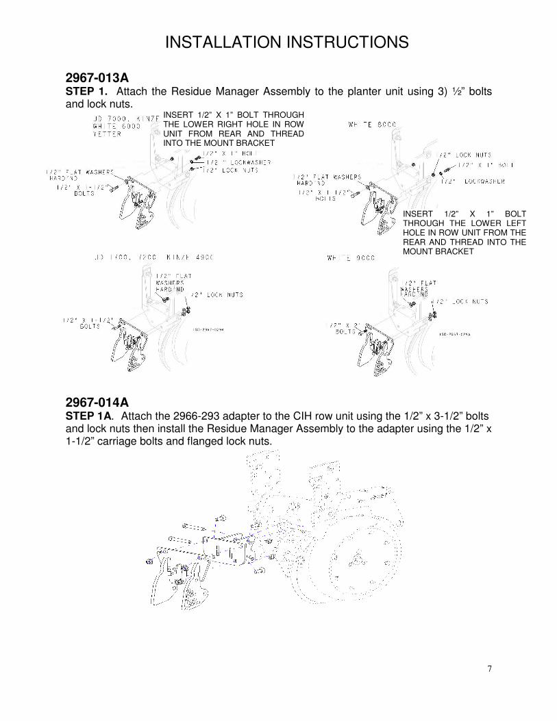
2967-013A STEP 1. Attach the Residue Manager Assembly to the planter unit using 3) ½” bolts and lock nuts.
2967-014A STEP 1A. Attach the 2966-293 adapter to the CIH row unit using the 1/2” x 3-1/2” bolts and lock nuts then install the Residue Manager Assembly to the adapter using the 1/2” x 1-1/2” carriage bolts and flanged lock nuts.
INSERT 1/2” X 1” BOLT THROUGH THE LOWER RIGHT HOLE IN ROW UNIT FROM REAR AND THREADINTO THE MOUNT BRACKET
INSERT 1/2” X 1” BOLT THROUGH THE LOWER LEFT HOLE IN ROW UNIT FROM THE REAR AND THREAD INTO THE MOUNT BRACKET
8
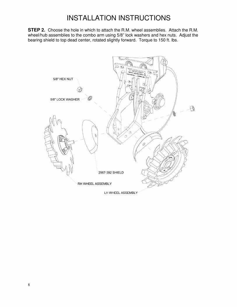
INSTALLATION INSTRUCTIONS STEP 2. Choose the hole in which to attach the R.M. wheel assemblies. Attach the R.M. wheel/hub assemblies to the combo arm using 5/8” lock washers and hex nuts. Adjust the bearing shield to top dead center, rotated slightly forward. Torque to 150 ft. lbs.
9
OPERATION
CAUTION: Where rocks are present the residue manager should be set in the “float” position, not locked down.
Adjust the residue manager to move crop residue aside and not move any soil. Adjustments to the residue manager may have to be made when changing field conditions and type and amount of residue. Use the handle for leverage when changing depth settings.
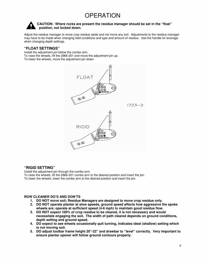
“FLOAT SETTINGS” Install the adjustment pin below the combo arm. To raise the wheels, lift the 2966-201 and move the adjustment pin up. To lower the wheels, move the adjustment pin down.
“RIGID SETTING” Install the adjustment pin through the combo arm. To raise the wheels, lift the 2966-201 combo arm to the desired position and insert the pin. To lower the wheels, lower the combo arm to the desired position and insert the pin.
ROW CLEANER DO’S AND DON’TS
1. DO NOT move soil; Residue Managers are designed to move crop residue only. 2. DO NOT operate planter at slow speeds, ground speed affects how aggressive the spoke
wheels are; operate at sufficient speed (4-6 mph) to maintain good residue flow. 3. DO NOT expect 100% of crop residue to be cleared, it is not necessary and would
necessitate engaging the soil. The width of path cleared depends on ground conditions, depth setting and ground speed.
4. DO expect to see wheels occasionally quit turning, indicates ideal (shallow) setting which is not moving soil.
5. DO adjust toolbar frame height 20”-22” and drawbar to “level” correctly. Very important to ensure planter opener will follow ground contours properly.
10
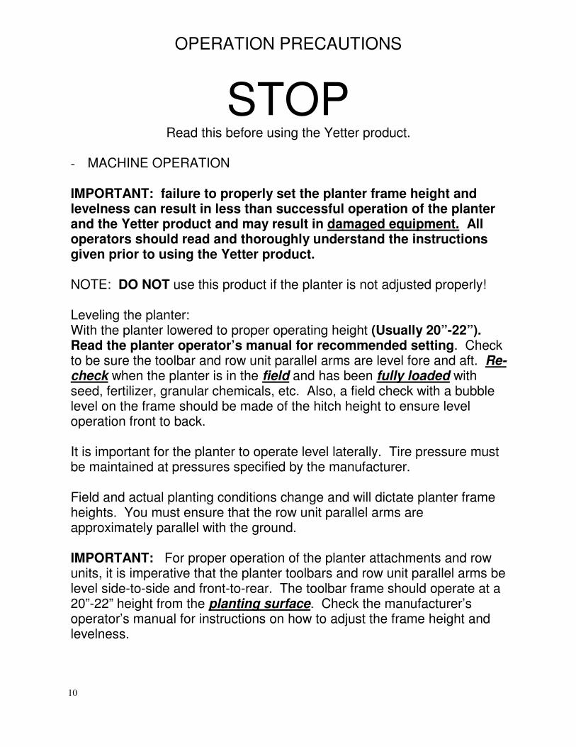
OPERATION PRECAUTIONS
STOP Read this before using the Yetter product.
- MACHINE OPERATION IMPORTANT: failure to properly set the planter frame height and levelness can result in less than successful operation of the planter and the Yetter product and may result in damaged equipment. All operators should read and thoroughly understand the instructions given prior to using the Yetter product. NOTE: DO NOT use this product if the planter is not adjusted properly! Leveling the planter: With the planter lowered to proper operating height (Usually 20”-22”). Read the planter operator’s manual for recommended setting. Check to be sure the toolbar and row unit parallel arms are level fore and aft. Re-check when the planter is in the field and has been fully loaded with seed, fertilizer, granular chemicals, etc. Also, a field check with a bubble level on the frame should be made of the hitch height to ensure level operation front to back. It is important for the planter to operate level laterally. Tire pressure must be maintained at pressures specified by the manufacturer. Field and actual planting conditions change and will dictate planter frame heights. You must ensure that the row unit parallel arms are approximately parallel with the ground. IMPORTANT: For proper operation of the planter attachments and row units, it is imperative that the planter toolbars and row unit parallel arms be level side-to-side and front-to-rear. The toolbar frame should operate at a 20”-22” height from the planting surface. Check the manufacturer’s operator’s manual for instructions on how to adjust the frame height and levelness.
11
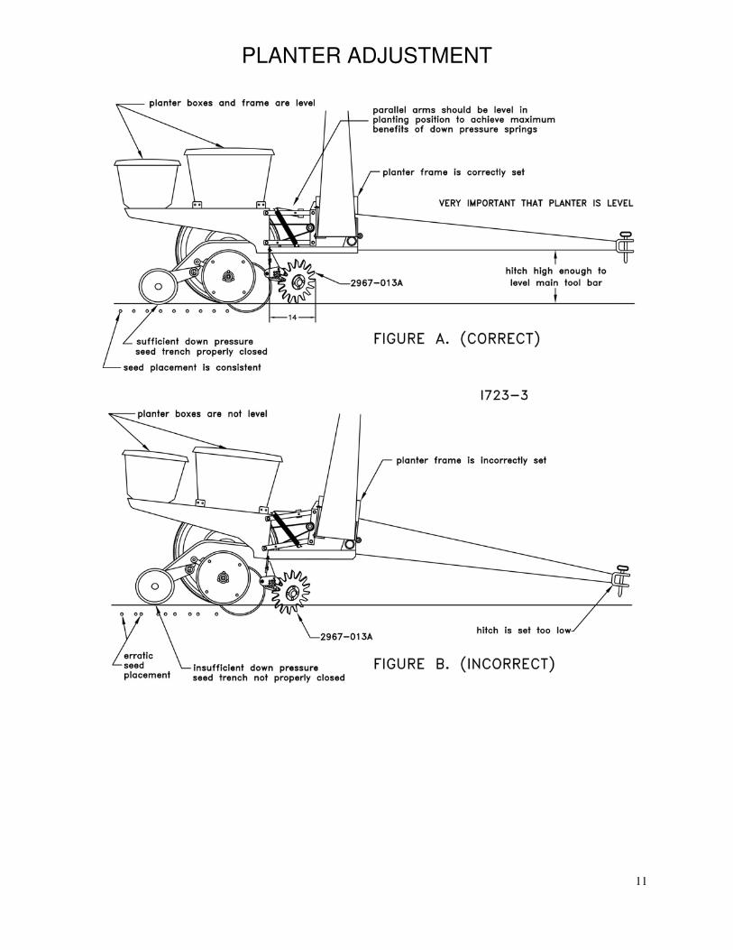
PLANTER ADJUSTMENT
12
MAINTENANCE
Regularly inspect the residue manager for loose or worn parts. Repair and replace as needed.
BEARING ASSEMBLY AND LUBRICATION
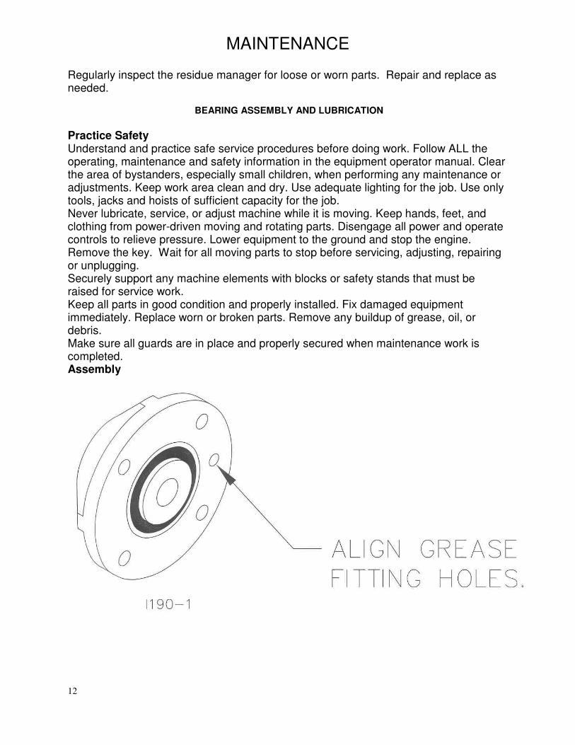
Practice Safety Understand and practice safe service procedures before doing work. Follow ALL the operating, maintenance and safety information in the equipment operator manual. Clear the area of bystanders, especially small children, when performing any maintenance or adjustments. Keep work area clean and dry. Use adequate lighting for the job. Use only tools, jacks and hoists of sufficient capacity for the job. Never lubricate, service, or adjust machine while it is moving. Keep hands, feet, and clothing from power-driven moving and rotating parts. Disengage all power and operate controls to relieve pressure. Lower equipment to the ground and stop the engine. Remove the key. Wait for all moving parts to stop before servicing, adjusting, repairing or unplugging. Securely support any machine elements with blocks or safety stands that must be raised for service work. Keep all parts in good condition and properly installed. Fix damaged equipment immediately. Replace worn or broken parts. Remove any buildup of grease, oil, or debris. Make sure all guards are in place and properly secured when maintenance work is completed. Assembly
13
MAINTENANCE
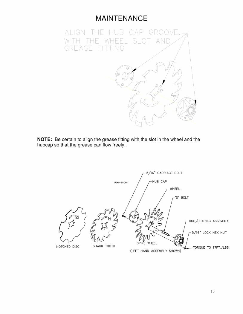
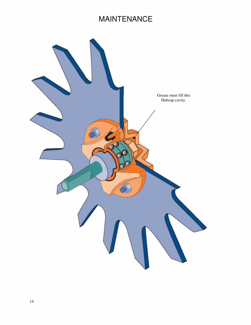
NOTE: Be certain to align the grease fitting with the slot in the wheel and the hubcap so that the grease can flow freely.
14
MAINTENANCE
Grease must fill this
Hubcap cavity.
15
MAINTENANCE
Lubrication
CAUTION: To help prevent serious injury or death to you or others caused by unexpected movement, service machine on a level surface. Lower
machine to ground or sufficiently lock or block raised machine before servicing. If machine is connected to tractor, engage parking brake and place transmission in "PARK", shut off engine and remove key. If machine is detached from tractor, block wheels and use shop stands to prevent movement.
CAUTION: Do not clean, lubricate, or adjust machine while in motion.
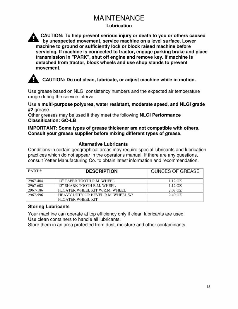
Use grease based on NLGI consistency numbers and the expected air temperature range during the service interval.
Use a multi-purpose polyurea, water resistant, moderate speed, and NLGI grade #2 grease. Other greases may be used if they meet the following NLGI Performance Classification: GC-LB
IMPORTANT: Some types of grease thickener are not compatible with others. Consult your grease supplier before mixing different types of grease.
Alternative Lubricants
Conditions in certain geographical areas may require special lubricants and lubrication practices which do not appear in the operator's manual. If there are any questions, consult Yetter Manufacturing Co. to obtain latest information and recommendation. PART # DESCRIPTION OUNCES OF GREASE
2967-404 13” TAPER TOOTH R.M. WHEEL 1.12 OZ
2967-602 13” SHARK TOOTH R.M. WHEEL 1.12 OZ
2967-186 FLOATER WHEEL KIT W/R.M. WHEEL 2.08 OZ
2967-596 HEAVY DUTY OR BEVEL R.M. WHEEL W/
FLOATER WHEEL KIT
2.40 OZ
Storing Lubricants
Your machine can operate at top efficiency only if clean lubricants are used. Use clean containers to handle all lubricants. Store them in an area protected from dust, moisture and other contaminants.
16
MAINTENANCE
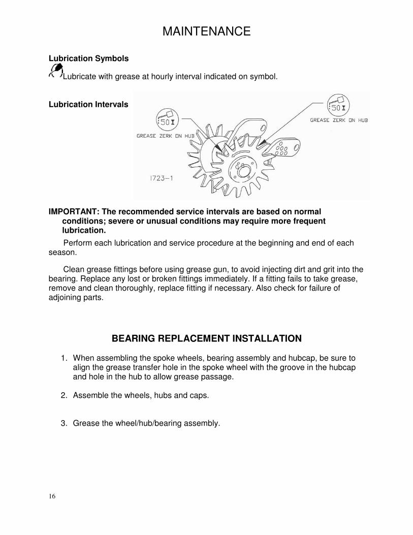
Lubrication Symbols
Lubricate with grease at hourly interval indicated on symbol. Lubrication Intervals
IMPORTANT: The recommended service intervals are based on normal conditions; severe or unusual conditions may require more frequent lubrication.
Perform each lubrication and service procedure at the beginning and end of each season.
Clean grease fittings before using grease gun, to avoid injecting dirt and grit into the bearing. Replace any lost or broken fittings immediately. If a fitting fails to take grease, remove and clean thoroughly, replace fitting if necessary. Also check for failure of adjoining parts.
BEARING REPLACEMENT INSTALLATION 1. When assembling the spoke wheels, bearing assembly and hubcap, be sure to
align the grease transfer hole in the spoke wheel with the groove in the hubcap and hole in the hub to allow grease passage.
2. Assemble the wheels, hubs and caps.
3. Grease the wheel/hub/bearing assembly.
17
MAINTENANCE
Storing the Equipment Store the machine in an area away from human activity
Store machine in RAISED position.
Install service locks on all wheel cylinders.
At the end of the season, the machine should be thoroughly inspected and prepared for storage. Repair or replace any worn or damaged components to prevent down time at the start of the next season. Store machine under cover with all parts in operating condition.
• Clean machine thoroughly to remove all dirt, debris and crop residue, which would hold moisture and cause rusting.
• Inspect machine for worn or broken parts. See your Yetter Farm Equipment dealer during the off-season so that parts or service can be acquired when machine is not needed in the field.
• Lubricate bearings as outlined in the Lubrication section
• Paint all parts which are chipped or worn and require repainting.
• Store machine in a clean, dry place with the planting unit out of the sun.
• If the machine cannot be stored inside, cover with a waterproof tarpaulin and tie securely in place.
• Do not allow children to play on or around the machine
18
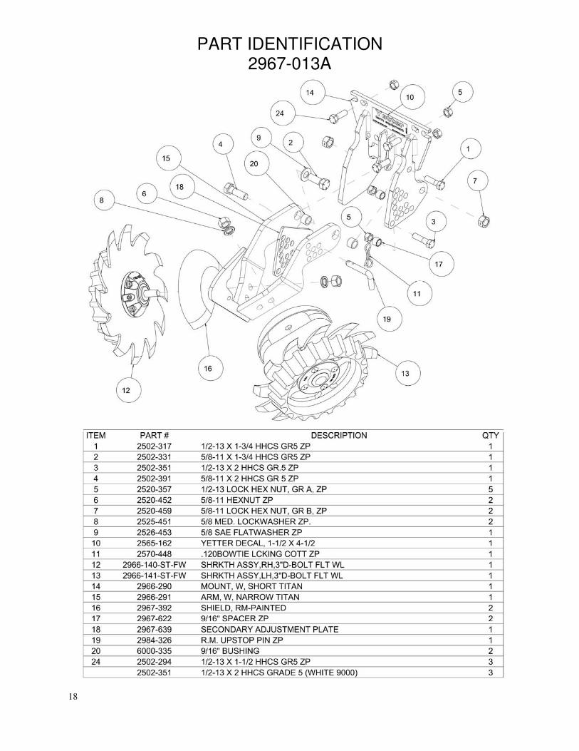
PART IDENTIFICATION 2967-013A
19
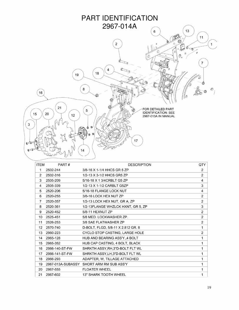
PART IDENTIFICATION 2967-014A

20
Our name Is getting known
Just a few years ago, Yetter products were sold primarily to the Midwest only. Then we embarked on a program of expansion
and moved into the East, the South, the West and now north into Canada. We’re even getting orders from as far away as
Australia and Africa.
So, when you buy Yetter products . . .you’re buying a name that’s recognized. A name that’s known and respected. A name that’s become a part of American agriculture and has become synonymous with quality
and satisfaction in the field of conservation tillage.
Thank you.
YETTER MANUFACTURING CO.
Colchester, IL 62326-0358 • 309/776-4111 Toll Free 800/447-5777
Fax 309/776-3222 Website: WWW.YETTERCO.COM E-MAIL: [email protected]
2565-748_I • JULY 2017