Embed Size (px)
Citation preview

Cooper Industries Crouse-Hinds Division Crouse-Hinds Airport Lighting Products 1200 Kennedy Road Windsor, CT 06095 860 683-4300 Fax 860 683-4354 Title:
Copyright © 2008 Cooper Technologies Company
DOCUMENT 9540 January 7, 2008 Revision W
INSTRUCTION MANUAL
L-828 & L-829 CONSTANT CURRENT REGULATOR
SERIES 82860-D (L-828,60HZ) & 82960-D (L-829,60HZ)
10KW, 6.6A; 15, 20, 30KW, 6.6 & 20A;
82850-D (L-828, 50HZ) & 82950-D (L-829, 50HZ)
10KW, 6.6A; 15 , 20, 30KW, 6.6 & 20A;

9540 Rev. W
CONFIGURATION RECORD
The following information is specific to the equipment described herein as shipped from the factory and should be retained. It should be provided when contacting the factory about this equipment for any reason. Constant Current Regulator, FAA Type Manufacturer’s Part Number Serial Number Date of Manufacture Factory Installed Options: OPTION/PART NUMBER DESCRIPTION
ii

9540 Rev. W
REVISIONS
REV. DESCRIPTION LTR. DATE APVL A Added Page 38.1; updated PCB on Pg.38
A96- 026
1/17/96 RBM
B Item 22, Pg’s 53 & 60, added p/n 32270; Item 30, Pg’s 57 & 65, added p/n 32271; corrected page numbering.
A96- 082
11/19/96 JAS
C Deleted 2.1.5.3 on page 7; 31879-3l was 31879-1l, P/N 32277-1 was 31984-1 on page 49;P/N 32323 was 32042-X-Y-6H, P/N 32277-1 was 31984-1 on page 55; P/N 32323 was 32042-X-Y-5H,P/N 32277-1 was 31984-1 on page62.
A97- 211
4/15/97 JAS
D 1) Revised wiring diagram Figure 4-4, secondary of T20 was 12,6,0
A97-327 6/5/97 JAS
E 1) Pg. 39. Fig. 4-4, re-routed wire 13 from F1 to T20. A97- 387
7/28/97 JAS
F Sheet 38, S2, S3 & S4 was S2-S4 A98-071 6/1/98 RBM G
Changed notes on Figure 4-3c, Sheet 38 A98- 395
1/11/99 JAS
H 1) Pg. 39, F1 fuse value for 30KW, 208 & 220V was 2 Amp; 2) Revised pg. 40 and added pg. 40.1; 3) Pg. 45, Item 26 P/N was”10053-266 (shown), 10047-1751”; 4) Pg. 46, changed P/N and picture of Item 26; 5) Pg. 52 & 59, Item 15 P/N 10047-1305 was P/N 10047-1141, Fuse, 2 Amp, Buss P/N MDL-2, added Item 19, P/N 32605 and Item 21 P/N’s 10047-2424and 10047-1444; 6) Pg. 53, Item 26 P/N was 10053-682 & Mfg. P/N was Ross Eng. P/N E25-NO-0-84-CH; 7) Pg. 54 & 61 added Item 27, RV1 Varistor Assy P/N 32606 and Item 26 Contactor, P/N 10047-2737 was P/N 32093; 8) Pg. 57 & 65, deleted item 30 P/N 32271, Potential Transformer (30KW, 6.6A Units only)
A200- 296
3/22/01 WAG
J
1) Added pilot relay (K2) and related data for 30 KW, 208V and 220V Regulators
A201-175 7/11/01 DMG
K R1 Assy in Figures 1 & 2 was R1, 2K, 50W; Parts List Item 26 10047-2774 was 10047-2737; Deleted Parts List Item 32 (K2 ref) was 10047-1898 Relay Socket and Deleted Item 33 (K2) was 10047-1899 Relay Octal Plug (30KW, 208/220V only)
A201-217 10/5/01 GFR
L 1) Added Pilot Relay (K2) and related data to 2400V Regulators
A201-239 11/12/01 GFR
M Update Figures 4-5, 5-3, & 5-4 to show latest mfg; Pg. 52, item 21, 32414 was 30190 & modified voltages; Pg. 53, item 26, 10047-2757 was 125A; Pg. 54 & 61, item 26, del 10047-1249, 32085, 32087 & adjusted voltages; Pg. 57, added 2400V only ref to items 32 & 33; Pg. 59, item 21, modified voltages; Pg. 65, deleted items 32 & 33, 10047-1898 & 10047-1899; Pg. 66, 1 amp fuse was 10047-1205 & added 10047-1141
A203-043 3/24/03 GFR
iii

9540 Rev. W
REVISIONS
REV. DESCRIPTION LTR. DATE APVL N Updated Schematic Figure 4-4; Updated T3 Wiring
Charts Figures 4-5, 4-5a; Added F1 (2 Amp) to Item 15 Pg 52 and Pg 59; Updated T3 configuration Item 21 Pg 52 and Pg 59; Updated K1 Item 26 Pg 54 and Pg 61
A203- 152
9/29/03 GFR
P Pg 19 & 43, revised pictorial; Pgs 51 & 58, item 1 P/N was 31490 & deleted item 2, P/N 31544 & deleted item 5, P/N 31509
A205-184 12/21/05 PG
R 1.2.3.1, Specification 150/5345-10F was 10E; cover page, revised copyright
A206-260 8/10/06 PG
S Pg 60, C1 P/N for 10 kW was 30062-01, for 15 kW was 30062-04 & for 20 kW was 30062-02; pg 53 item 23 & pg 60 item 23, added note to item that it is not field replaceable
A206-431 11/9/06 PG
T Title pg, copyright 2007 was 2006; 50 Hz parts list, Item 26 P/N 10047-2990 was 32084, Contactor, 94A, 2 pole & 10047-2989 was 10047-1249, Contactor, 75A, 2 pole, Square D P/N 8910 DPA62-V02-y236 & 10047-2991 was 10047-2774, Joslyn Clark P/N CVC77U032006-76 & deleted 32085, Contactor, 120A, 2 pole, for K1 (208, 22, 230, 240V-20 KW); Item 27 P/N 31665-2 was 31665 & deleted P/N 32606 , RV1 for 208 & 220V 30 KW
A207-186 6/11/07 PG
U 50 Hz parts list, item 26, added 10047-2774, 10047-1990 description was 125A & usage was 208-240V, 15 & 20 KW & 380-415V, 30 KW and 10047-2989 description was 80A & usage was 10 KW all & 380-415V, 15 & 20 KW and 10047-2991 description was 200A & usage was 208-240V, 30 KW
A207-201 6/21/07 PG
V Table 3-1, revised input currents A207-318 12/20/07 PG W Revised copyright to 2008; Figure 4-5 & 4-5A, 208V,
30 kW, wire #43 was #44 and wire #44 was #43 and item number 52 was 53 and item number 53 was 52; parts list item 21, added mfg P/N TB-81305 TO 10047-2424 & TB-8123 to 10047-1444
A208-002 1/7/08 PG
iii.a

9540 Rev. W
LIMITED PRODUCT WARRANTY
THE FOLLOWING WARRANTY IS EXCLUSIVE AND IN LIEU OF ALL OTHER WARRANTIES, WHETHER EXPRESS, IMPLIED OR STATUTORY, INCLUDING, BUT NOT BY WAY OF LIMITATION, ANY WARRANTY OF MERCHANTABILITY OR FITNESS FOR ANY PARTICULAR PURPOSE. Crouse-Hinds Airport Lighting Products (the “Company”) warrants to each original Buyer of Products manufactured by the Company that such Products are, at the time of delivery to the Buyer, free of material and workmanship defects, provided that no warranty is made with respect to: a) any Product which has been repaired or altered in such a way, in Company’s judgment, as to
affect the Product adversely; b) any Product which has, in Company’s judgment, been subject to negligence, accident or
improper storage; c) any Product which has not been operated and maintained in accordance with normal practice
and in conformity with recommendations and published specification of Company; and, d) any Product, component parts or accessories manufactured by others but supplied by
Company (any claims should be submitted directly to the manufacturer thereof). Crouse-Hinds Airport Lighting Product’s obligation under this warranty is limited to use reasonable effects to repair or, at its option, replace, during normal business hours at any authorized service facility of Company, any Products which in its judgment proved not to be as warranted within the applicable warranty period. All costs of transportation of Products claimed not to be as warranted and of repaired or replacement Products to or from such service facility shall be borne by Purchaser. Company may require the return of any Product claimed not to be as warranted to one of its facilities as designed by Company, transportation prepaid by Purchaser, to establish a claim under this warranty. The cost of labor for installing a repaired or replacement product shall be borne by Purchaser. Replacement parts provided under the terms of this warranty are warranted for the remained of the warranty period of the Products upon which they are installed to the same extent as if such parts were original components thereof. Warranty services provided under the Agreement do not assure uninterrupted operations of Products; Company does not assume any liability for damages caused by any delays involving warranty service. The warranty period for the Products is 24 months from date of shipment or 12 months from date of first use whichever occurs first.
iv

9540 Rev. W
SAFETY NOTICES
This equipment is normally used or connected to circuits that may employ voltages which are dangerous and may be fatal if accidentally contact by operating or maintenance personnel. Extreme caution should be exercised when working with this equipment. While practical safety precautions have been incorporated in this equipment, the following rules must be strictly observed.
KEEP AWAY FROM LIVE CIRCUITS Operating and maintenance personnel must at all times observe all safety regulations. Do not perform maintenance on internal components or re-lamp with power ON.
RESUSCITATION
Maintenance personnel should familiarize themselves with the technique for resuscitation found in widely published manuals of first aid instructions.
v

9540 Rev. W
TABLE OF CONTENTS
Title Page . . . . . . . . . . . . . . . . . . . . . . . . . . . . . . . . . . . . . . . . . . . . . . . . . i Configuration Record. . . . . . . . . . . . . . . . . . . . . . . . . . . . . . . . . . . . . . . . . ii List of Effective Pages . . . . . . . . . . . . . . . . . . . . . . . . . . . . . . . . . . . . . . . . iii Limited Product Warranty . . . . . . . . . . . . . . . . . . . . . . . . . . . . . . . . . . . . . iv Safety Notices . . . . . . . . . . . . . . . . . . . . . . . . . . . . . . . . . . . . . . . . . . . . . . v Table of Contents . . . . . . . . . . . . . . . . . . . . . . . . . . . . . . . . . . . . . . . . . . . . vi SECTION 1. GENERAL INFORMATION 1.1 Introduction . . . . . . . . . . . . . . . . . . . . . . . . . . . . . . . . . . . . . . 1 1.2 Equipment Description . . . . . . . . . . . . . . . . . . . . . . . . . . . . . . . 1 1.3 Installation Requirements . . . . . . . . . . . . . . . . . . . . . . . . . . . . . 3 SECTION 2. TECHNICAL DESCRIPTION 2.1 Theory of Operation . . . . . . . . . . . . . . . . . . . . . . . . . . . . . . . . . . 5 SECTION 3. INSTALLATION AND OPERATION 3.1 Installation . . . . . . . . . . . . . . . . . . . . . . . . . . . . . . . . . . . . . . . . 10 3.2 Operation . . . . . . . . . . . . . . . . . . . . . . . . . . . . . . . . . . . . . . . . . 14 SECTION 4. MAINTENANCE 4.1 Periodic Maintenance . . . . . . . . . . . . . . . . . . . . . . . . . . . . . . . 22 4.2 Corrective Maintenance . . . . . . . . . . . . . . . . . . . . . . . . . . . . . . 23 4.3 Problem Solving Guide . . . . . . . . . . . . . . . . . . . . . . . . . . . . . . . 23 SECTION 5. PARTS LIST 5.1 Scope . . . . . . . . . . . . . . . . . . . . . . . . . . . . . . . . . . . . . . . . . . . . 42 5.2 Arrangement . . . . . . . . . . . . . . . . . . . . . . . . . . . . . . . . . . . . . . 42 5.3 Reference Designation . . . . .. . . . . . . . . . . . . . . . . . . . . . . . . . . 42 5.4 Option Parts . . . . . . . . . . . . . . . . . . . . . . . . . . . . . . . . . . . . . . . 42 5.5 Recommended Spares . . . . . . . . . . . . . . . . . . . . . . . . . . . . . . . . 51
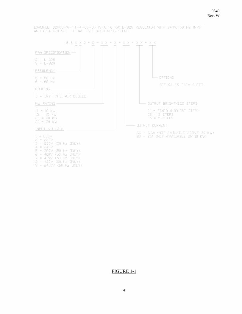
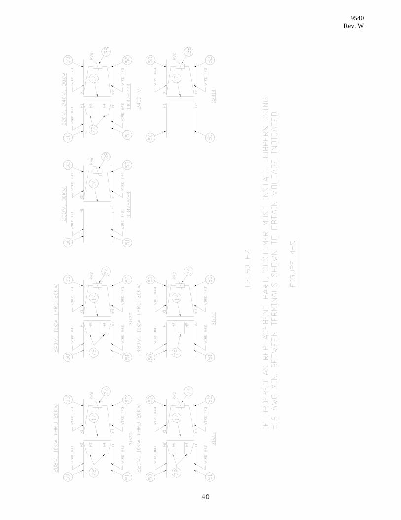
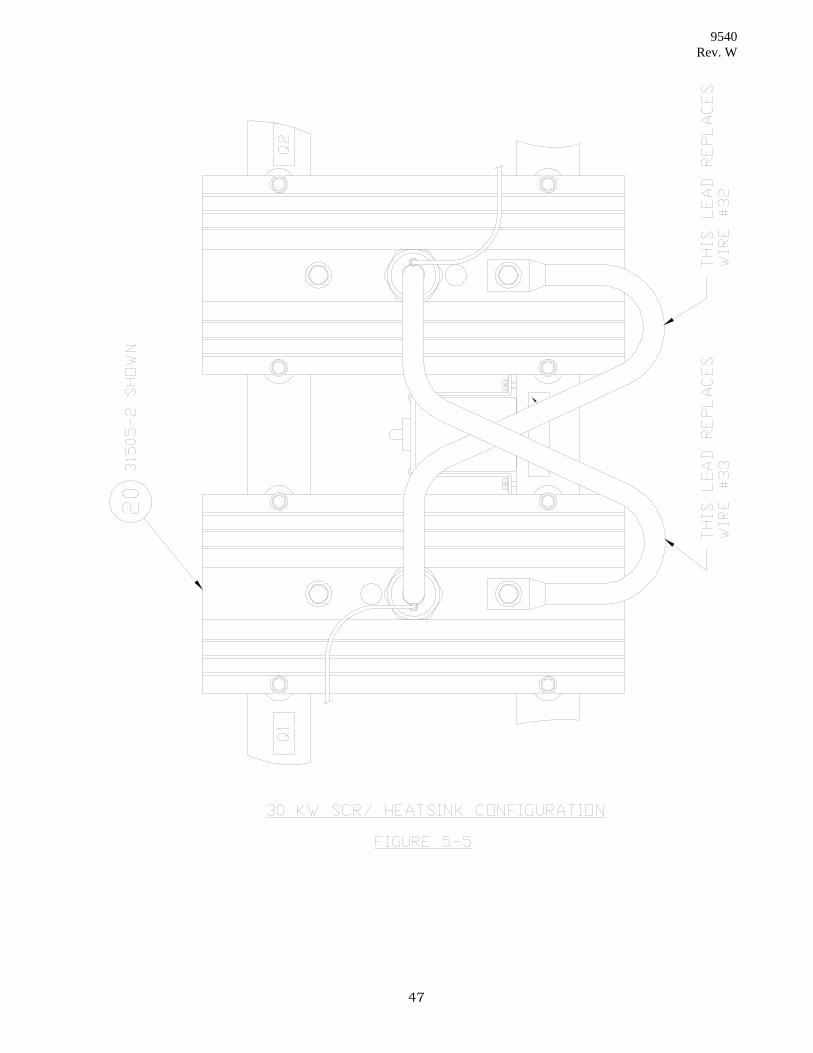
FIGURES Figure 1-1 - Catalog Number Breakdown . . . . . . . . . . . . . . . . . . . . . . . . . 4 Figure 3-1 - Mechanical Dimensions . . . . . . . . . . . . . . . . . . . . . . . . . . . . 19 Figure 3-2 - Controls and Indicators . . . . . . . . . . . . . . . . . . . . . . . . . . . . 20 Figure 3-3 - Calibration Flow Chart . . . . . . . . . . . . . . . . . . . . . . . . . . . . 21 Figure 4-1 - Control System Connector Operation . . . . . . . . . . . . . . . . . . 28 Figure 4-2 - Standard Model Diagnostic Indicators . . . . . . . . . . . . . . . . . 29 Figure 4-3 - Remote Control Connections . . . . . . . . . . . . . . . . . . . . . . . 37 Figure 4-3c - Remote Control Jumper Connections . . . . . . . . . . . . . . . . . 38 Figure 4-3d - Switch Configurations . . . . . . . . . . . . . . . . . . . . . . . . . . . . . 38.1 Figure 4-4 - System Wiring Diagram . . . . . . . . . . . . . . . . . . . . . . . . . . . 39 Figure 4-5 - Control Transformer Wiring Details . . . . . . . . . . . . . . . . . . . 40 Figure 4-6 - Monitor Wiring . . . . . . . . . . . . . . . . . . . . . . . . . . . . . . . . . . 41 Figure 5-1 - Front Parts Identification . . . . . . . . . . . . . . . . . . . . . . . . . . 43 Figure 5-2 - Upper Internal Parts Identification. . . . . . . . . . . . . . . . . . . . 44 Figure 5-3 - Lower Internal Parts Identification. . . . . . . . . . . . . . . . . . . . 45 Figure 5-4 - 2400V K1, LA1A & LA1B Configuration . . . . . . . . . . . . . . . . 46 Figure 5-5 - 30KW Heatsink Detail . . . . . . . . . . . . . . . . . . . . . . . . . . . . . 47 Figure 5-6 - Rear Parts Identification. . . . . . . . . . . . . . . . . . . . . . . . . . . . 48 Figure 5-7 - Control Box Circuit Card Identification. . . . . . . . . . . . . . . . . 49 Figure 5-8 - Transformer (T20 &T5) Location . . . . . . . . . . . . . . . . . . . . 50
vi

9540 Rev. W
TABLE OF CONTENTS
Cont'd TABLES AND CHARTS Table 3-1 - Power Requirements . . . . . . . . . . . . . . . . . . . . . . . . . . . . . . . . . 10 Display Messages and What They Mean . . . . . . . . . . . . . . . . . . . . . . . . . . . 25 Quick Problem Solving Checklist . . . . . . . . . . . . . . . . . . . . . . . . . . . . . . . . 26 Power Supply Problem Checklist . . . . . . . . . . . . . . . . . . . . . . . . . . . . . . . . . 30 Protection Problem Checklist . . . . . . . . . . . . . . . . . . . . . . . . . . . . . . . . . . . 31 Regulation Problem Checklist . . . . . . . . . . . . . . . . . . . . . . . . . . . . . . . . . . . 32 Local Control Problem Checklist. . . . . . . . . . . . . . . . . . . . . . . . . . . . . . . . . 33 Remote Control Problem Checklist . . . . . . . . . . . . . . . . . . . . . . . . . . . . . . . 34 Digital Problem Checklist. . . . . . . . . . . . . . . . . . . . . . . . . . . . . . . . . . . . . . 35 Display Problem Checklist . . . . . . . . . . . . . . . . . . . . . . . . . . . . . . . . . . . . . 36 Parts List - 60 Hz . . . . . . . . . . . . . . . . . . . . . . . . . . . . . . . . . . . . . . . . . . . . 51 Parts List - 50 Hz . . . . . . . . . . . . . . . . . . . . . . . . . . . . . . . . . . . . . . . . . . . . 58
vii

9540 Rev. W
SECTION I. GENERAL INFORMATION
1.1 INTRODUCTION 1.1.1 Purpose
This instruction manual provides information for installing and maintaining air-cooled (dry) FAA Type L-828 & L-829 Constant Current Regulators manufactured by Crouse-Hinds Airport Lighting Products, Windsor, Connecticut 06095, U.S.A.
1.1.2 Applicability
Only 10 - 30 KW regulators bearing Crouse-Hinds catalog number series 82860-D, 82960-D, 82850-D, & 82950-D are covered by this manual. Refer to Figure 1-1 for complete part number information. Instructions for standard options are provided as supplements to this manual.
1.2 EQUIPMENT DESCRIPTION 1.2.1 Features
The Constant Current Regulator is a power supply designed for precision operation of airfield lighting. The output current is regulated within +/-1% at any load and for line voltages form +10% to -5% of nominal. The three or five discrete brightness steps conform to FAA standards. The regulator may be controlled both locally and from a remote location.
Protective circuits are provided to sense an overcurrent or an open circuit in the series lighting loop and shutdown the regulator. The front panel display alerts maintenance personnel to the nature of the shutdown. The protective circuitry can be reset by setting the regulator control switch to off for 1 second. Provided no fault condition remains, setting the control switch to the desired brightness step will restore operation.
The regulator may be connected directly to an FAA approved load switching device. No regulator malfunction or damage to the series lighting loop will occur.
1.2.2 Options
This regulator can be factory supplied with various options. Contact Crouse-Hinds Airport Lighting Products for a current list of options.
1

9540 Rev. W
1.2.3 Specification 1.2.3.1 FAA Classification
Specification: Constant Current Regulator manufactured and qualified to FAA Advisory Circular 150/5345-10F
Type: L-828 Regulator L-829 Regulator (with monitoring)
Class: 1 - 6.6 amperes output current (10KW, 15KW, 20KW, 30KW) 2 - 20 amperes output current (15KW, 20KW, 30KW) Style: 1 - 3 Brightness Steps: 4.8, 5.5, 6.6 amperes or 14.5, 16.7, 20.0
amperes 2 - 5 Brightness Steps: 2.8, 3.4, 4.1, 5.2, 6.6 amperes or 8.5, 10.3,
12.4, 15.8, 20.0 amperes Ratings: Sizes - 10KW, 15KW, 20KW, 30KW
Voltages - 208, 220, 240, 480, 2400V; 60 Hz 208, 220, 230, 240, 380, 400 & 415; 50 Hz
1.2.3.2 Electrical Characteristics Primary Power:
Refer to Table 3-1 for ampacity information based on regulator size and line voltage. Remote Control Power:
(a) Internal Supply - 120 VAC, standard (Other voltages optional)
(b) External Supply - 120 VAC, Standard (Other voltages optional) 1.2.3.3 Physical Characteristics
Dimensions:
Refer to Outline Drawings, Figure 3-1. Weight: 10 KW - 750 lbs. 15 KW - 800 lbs. 20 KW - 925 lbs. 30 KW - 1070 lbs.
2

9540 Rev. W
Mechanical:
The regulator has a louvered sheet steel enclosure painted blue with light gray accents. Removable front panels provides access to line and load connections. The electronic controls are housed in a hinged compartment which provides access to the remote control terminals when open. Other removable panels allow easy access to other customer serviceable parts. A control power safety interlock and line power warning indicator are standard.
Environmental: Temperature: -40 degrees C to + 55 degrees C (-40 degrees F to +131 degrees F) Relative Humidity: 10 percent to 95 percent Altitude: Zero to 6,600 feet (2000 m) 1.3 Installation Requirements
The regulator is shipped from the factory complete and ready to install. The agency responsible for installation must supply all necessary connectors, wire and conduit. The regulator is for indoor use only. It may be floor mounted, or mounted on a rack or shelf. However, floor mounting is recommended. Rack mounting schemes are the sole responsibility of the engineer and/or contractor.
3
9540 Rev. W
FIGURE 1-1
4
9540 Rev. W
SECTION 2. TECHNICAL DESCRIPTION
2.1 THEORY OF OPERATION (BASIC REGULATOR)
The information presented here applies to a standard model Constant Current Regulator (CCR). Regulators supplied with options may have minor operating differences, but the basic operation is the same for all units.
Many functions in the CCR are controlled by a custom programmed electronic circuit. This device performs brightness step and digital display control, open circuit and over-current sensing, and handles system fault conditions. Several optional features also use the programmed circuit to reduce the amount of additional circuitry required. Each of the standard functions is discussed in detail in the following paragraphs. Optional functions are discussed in Supplemental sections of this manual.
2.1.1 Current Regulation
A ferro-resonant transformer is conjunction with a pair of silicon controlled rectifiers (SCR) is used for current regulation. This design provides precise control regardless of the load size or line voltage. For very low loads or low brightness settings, the SCR conduction angle will be large. At increased loads or higher brightness settings, the conduction angle will be smaller. The SCR gating signal is controlled using closed-loop electronic feedback control. Load current is sensed by a current transformer which generates an analog signal. The signal is processed by an electronic circuit and compared to a predetermined reference. The result is a time delayed SCR control signal. This control signal is applied to a pulse transformer to generate a gating signal for the SCR’s.
2.1.2 Brightness Control
Each brightness step has a specific digital reference value stored in electronic memory. When the desired step is selected on the keypad, the proper memory value is converted to an analog signal. This signal is the reference used for comparison as discussed in paragraph 2.1.1. Refer to Section 3.2 for keypad operation. All remote brightness connections are electrically isolated form the control electronics by opto-couplers for transient protection.
5

9540 Rev. W
2.1.3 Remote Control Operation
The regulator can operate remotely using external switches connected to the remote control terminal block TB1. The exact wiring of these switches depends upon whether control power is obtained from the regulator internal supply or from an external source.
The regulator turns on to brightness B1 (or B10) when control power is applied to terminals CC and B1 (B10). To get a higher brightness, control power is applied to terminal B2, B3, B4 or B5. (For three-step regulators, apply control power to B30 or B100, for one-step regulators, apply control power to on). Only the terminal for the desired step and CC require control power. If two or more steps are energized together, the regulator will operate at the highest brightness step selected.
2.1.4 Digital Display
A multi-purpose Digital Display provides system operation data. Under normal conditions, the display shows the output current being supplied by the CCR. Under power-up and system fault conditions, it displays specific CCR status data (refer to paragraph 2.1.6).
2.1.5 Protective System 2.1.5.1 Overcurrent Protection
Overcurrent protection is triggered by comparison of the value of the feedback signal to predetermined limits. In the event of a minor overcurrent (between 5% and 25% above rated output), the control system responds within 5 seconds. If a major overcurrent (greater than 25% above rated output) occurs, the control system responds immediately. The response consists of de-energizing the load by opening the main contactor and providing status data to the digital display. To reset and re-energize the CCR, the keypad or remote brightness control switch must be set to OFF for at least one second.
2.1.5.2 Open-Circuited Load Protection
This protection is triggered by comparison of the value of the feedback signal to a minimum current level. If the current remains below 2 amps for about 1 second, the control system performs the same shutdown sequence as for overcurrent protection.
6

9540 Rev. W
2.1.5.3 2.1.5.4 Fuses
There are two fuses in the regulator for internal power supply protection. Fuse F1 protects the internal 120 VAC supply. Fuse F2 protects the remote control system supply.
2.1.5.5 Transient Protection Protection against transients from lightning or other sources is provided. Lightning
arrester LA1 protects the regulator power lines. Arresters LA2 and LA3 protect the regulator load lines. Varistors are provided on the control system assembly to protect it from transients on the power and control lines.
The lightning protection provided exceeds the requirements of the applicable Advisory Circular. Lightning is a naturally occurring phenomenon that varies in intensity and frequency based upon geographic location. Therefore, each installation should be evaluated to determine the need for additional lightning protection.
2.1.6 System Status Information
The CCR Digital Display is used during power-up and fault conditions to provide data regarding system status.
2.1.6.1 Power-Up
When power is applied to the CCR and when resetting from a latched fault mode, the control electronics performs a series of internal checks. If these are completed without incident, the control program number will be displayed for one second. The display will then begin to indicate CCR output current. If any check is not successfully completed, the system will "lock-up" preventing further operation.
2.1.6.2 Fault Status Messages
If the CCR control circuits detect an abnormal system shutdown, a message will automatically scroll across the display. When two or more fault conditions exist, the most recent occurrence is displayed. Messages are cleared when the system is reset or conditions return to normal. Refer to the Operation and Maintenance Sections for information on specific messages.
7

9540 Rev. W
2.1.7 Monitoring (L-829 Only)
The monitor circuitry utilizes runway circuit and regulator signals to perform its function. The runway circuit current and voltage are applied to current and potential transformers which perform isolation and step-down functions. The outputs of these transformers are applied to the electronic circuitry for processing. Also, the regulator brightness step signals are used by the monitor circuit.
2.1.7.1 Calibration (L-829 Only)
The calibration function is used to initialize the monitor. Upon selection of this mode, the operator is prompted for information on the specific load circuit and the desired alarm levels. When all the information has been entered, the monitor turns on the regulator and automatically adjusts itself for each brightness step. When this adjustment period is completed (usually within 2 minutes), the regulator is returned to the off state.
2.1.7.2 Normal Operation (L-829 Only)
The monitor continuously checks the runway circuit for faults. If no system faults have been detected, the monitor relay is in the energized state, the lampout warning and alarm relays are in the de-energized state, and the digital display functions as a true-RMS ammeter.
2.1.7.3 Regulator Power Fault (L-829 Only)
Any removal of input power will de-energize the monitor relay immediately, thereby signaling a regulator fault.
2.1.7.4 Protective Circuit Faults
In the event of an open circuit or overcurrent shutdown (see section 2.1.5), the monitor relay will be de-energized, signaling a regulator fault. In addition, the display will indicate what fault was encountered.
2.1.7.5 Brightness Step Fault (L-829 Only)
The monitor continuously checks the load current. This current value is compared with reference values selected by information from the brightness step control inputs. If the fault is continuously present for a five second period, the monitor relay is de-energized. A star (*) will appear to the right of the current reading on the digital display to indicate an alarm. This fault condition will reset when (1) the current returns to an in-tolerance value, (2) another properly operating brightness step is selected, (3) the regulator is set to the off position.
8

9540 Rev. W
2.1.7.6 Ten Percent Drop in Load Volt-Amperes (L-829 Only)
When a large change in load volt-amperes occurs, it is an indication that there are either two ground paths in the runway circuit or that there are many lamp burned out in the circuit. After a five second delay, the monitor relay is energized and a star (*) appears on the digital display to indicate an alarm. The fault condition remains until the situation is corrected. Connection of a runway circuit selector between the monitor and the loads will affect monitor performance.
2.1.7.7 Lamp Failure Detection (L-829 Only)
The lamp failure detection feature of the monitor is performed in essentially the same manner as the monitoring of volt-amperes discussed in paragraph 2.1.7.6. It is important to note that because of the method used to detect lampouts, it is not necessary to eliminate lamp shorting devices commonly used in some lighting circuits. If the number of lampouts exceeds the warning level entered by the user, the lampout warning relay will energize. If the number of lampouts exceed the alarm level entered by the user, the lampout alarm relay will energize as well, and the monitor relay will de-energize.
2.1.8 Elapsed Time Meter
The regulator is equipped with an electronic elapsed time meter. It records the total on-time of the regulator as well as the individual brightness steps. It will record up to 9999.9 hours of operation before starting at zero hours again. It can be viewed by entering the appropriate command at the regulator keypad. The total or individual brightness step on-time may be viewed while the regulator is in the on or off state.
9

9540 Rev. W
SECTION 3. INSTALLATION AND OPERATION
WARNING
INSTALLATION, SERVICE, MAINTENANCE OR OPERATION SHOULD BE PERFORMED BY QUALIFIED PERSONNEL ONLY.
3.1 INSTALLATION
The Constant Current Regulator is supplied ready for operation with all ordered options installed. When properly connected, no electrical adjustments other than noted in this section should be necessary before use.
3.1.1 Location
The regulator is designed for indoor locations meeting the environment specified in Section 1.2.3.3. The area should be clean and dry, protected from rain, snow, dust, etc., and have adequate ventilation. The equipment should be accessible to qualified personnel only.
3.1.2 Installation Drawings
Typical details are provided in Figure 3-1. Small removable panels are provided in the cabinet sides for convenient punching of conduit holes. These panels may be punched and attached to electrical conduits prior to installation. Should an error be made in the holes size or location, replacement panels are available.
3.1.3 Power Requirements
Table 3-1 lists the line current requirements for the different CCR power and voltage ratings. It is recommended that the distribution circuit breaker or fuses be sized to carry 125% of the rated circuit.
TABLE 3-1
POWER REQUIREMENTS
RATED RATED INPUT CURRENT INPUT (RMS AMPERES) VOLTAGE 10KW 15KW 20KW 30KW 208 53 80 106 159 220 50 75 100 150 230 48 72 96 143 240 46 69 92 138 380 29 43 58 87 400 28 41 55 83 415 27 40 53 80 480 23 34 46 69 2400 5 7 9 14
10

9540 Rev. W
3.1.4 Cable and Conduit
Do not locate line and load cables near sensitive control, radar, or communications lines. For suggested cable entrance locations, see Figure 5-1.
3.1.5 Installation Check List (1) Read these instructions before attempting installation.
Improper installation can damage this regulator and may void the warranty! If the equipment fails to perform properly at any step of this procedure, consult the troubleshooting guide in Section 4. Call Crouse-Hinds Airport Lighting Products (860) 683-4300 if further information is required during installation.
(2) Instructions for each equipment option included should also be read before proceeding with installation.
(3) SUGGESTION: To stay organized, make a check mark next to each step as
it is completed.
3.1.5.1 Mechanical Installation
1. Unpack the Constant Current Regulator, and check for any shipping damage.
2. For handling, a 2” fork-lift clearance is provided underneath the unit and 4
lifting lugs are provided. The regulator cover should be in place before lifting.
3. Refer to Figure 3-1 for mechanical installation details including required clearance for access and proper cooling.
3.1.5.2 Power Wiring and Checkout
1. Connect the ground conductor to the equipment ground terminal. It is located on the lower right side toward the front of the regulator. Caution: DO NOT connect counterpoise system to this terminal.
2. Verify that the line voltage is the same as the regulator nameplate voltage
rating. This is very important. CONNECTION TO THE WRONG LINE VOLTAGE MAY VOID THE WARRANTY.
3. Make required conduit holes as suggested in Figure 5-1.
11

9540 Rev. W
4. Connect the line voltage source to the input terminals. On 2400 volt WYE
units, the phase wire connects to the left terminal and the neutral connects to the right terminal. Do not rely on the ground wire as a neutral conductor.
5. Connect the series lighting circuit to the output terminals.
CAUTION: DO NOT MEGGER test the series lighting load while it is connected to the regulator.
6. Before connecting remote control lines, check regulator operation using the
front panel control switch. Follow steps A-C below. NOTICE: The regulator is equipped with a safety interlock. Be sure the control module is in its normal operating position before operating.
(A) Apply main power to the regulator.
(B) Operate the regulator at all brightness steps and check that the load
current levels are correct. See regulator nameplate for load current levels. (See Section 3.2 for keypad operation.)
IMPORTANT: Only a True RMS instrument can accurately measure the regulator output externally. Other instruments will provide improper readings. (C) Shut off main power to the regulator.
3.1.5.3 Control Wiring and Checkout
1. Connect remote control lines to terminal block TB1 using the appropriate wiring diagram. Refer to Figure 4-3.
Units which are shipped without an internal primary contactor (Option 92) must use 120Vac external control. See the instructions in the Option 92 Supplement for connection data. CAUTION: Incorrect wiring can cause malfunction or damage to the control system and possibly void the equipment warranty. Re-check these connections before operating.
12

9540 Rev. W
2. Make a final operation check using local and remote modes. Steps A-C
below.
(A) Apply main power to the regulator. (B) Operate the regulator in the local mode at all rightness steps and
check for correct current levels. (See Section 3.2 for keypad operation.)
(C) Operate the regulator in the Remote mode at all rightness steps and
check for correct current levels.
3.1.5.4 Monitor Wiring (L-829 Only)
This regulator is equipped with monitor relay, and a warning and alarm lampout relay. Connect the relay contacts to the monitor and lampout circuits per Figure 4-6. Each relay is rated for 120 VAC, 2 AMPS resistive load. The lampout relays are protected by 2 AMP fuses on the P.C. board.
3.1.5.5 Final Installation Steps
1. Make any option related connections discussed in the option Supplements. 2. Check that all cables an wiring are dressed within the cabinet. Reinstall all
covers.
13

9540 Rev. W
3.2 OPERATION
Figure 3-2 shows the standard controls and indicators on the front control panel.
3.2.1 Local Control Keypad
The local control keypad in conjunction with the digital display acts as an interactive control terminal for entering many different operational commands into the regulator. All keypad entries are echoed to the display for a period of five seconds for operator verification. In all instances, with two exceptions, the command sequence ends with the “E” key ( for Enter). The two exceptions are the “ABORT” command - which erases any un-entered command, and the “OFF” command - which will immediately turn off the regulator. To select an operating brightness step, simply press the keys according to the following list: (Remember - If you make a mistake, press “A” for ABORT.) To select OFF - Press “OFF” (no Enter required) or Press “BO (Enter)” or Press “0 (Enter)” To select Remote - Press “BB (Enter)” For 1 step regulators: To select ON - Press “B1 (Enter)” For 3 step regulators: To select B10 - Press “B10 (Enter)” or Press “B1 (Enter)” To select B30 - Press “B30 (Enter)” or Press “B2 (Enter)” To select B100 - Press “B100 (Enter)” or Press “B3 (Enter)” Entering B4 or B5 will result in an “ERROR” message.
14

9540 Rev. W
For 5 step regulators: To select B1 - Press “B1 (Enter)” To select B2 - Press “B2 (Enter)” To select B3 - Press “B3 (Enter)” To select B4 - Press “B4 (Enter)” To select B5 - Press “B5 (Enter)” Entering B10, B30 or B100 will result in an “ERROR” message. The brightness step command is stored in what is called ‘non-volatile’ electronic memory which is reliable for at least 10 years without power applied. This enables the regulator to immediately return to the selected brightness after a power interruption without operator intervention - just as if a rotary switch were used for brightness control.
3.2.2 Digital Display
During normal operation, the digital display functions as a True RMS ammeter, displaying the regulator load current. during power-up, under system fault conditions and when the keypad is in use, the display performs other functions. When these other functions are finished using the display, it automatically returns to reading load current. If the display is echoing keypad entries and no new entry is made within 5 seconds, the display returns to reading load current. They key entries are not lost. When power is initially applied to the regulator, the computer performs checks for valid operation. If these checks are completed successfully, the display will read “VER. X.X.”, where X.X is the software program version number, for a period of 1 second. Then normal display activity will begin. If the regulator should shut down due to system fault, a message will immediately begin to scroll across the display to explain the reason for the shut down. See Section 3.2.4 for further information. L-829 only If a lamp out monitor or brightness step monitor fault is detected, the display will continue to read current, but a “*” will appear to the right of the current reading. See Section 3.2.4 for further information.
15

9540 Rev. W
3.2.3 Monitor Calibration (L-829 only)
Calibrating the monitor does not require any tools. All that you need to know is the number of lamps in the circuit and at what number of lamp burn outs you want the warning and alarm functions to activate. If you wish, you may elect to calibrate the monitor in percentage rather than lamp count. This is recommended when there are different lamp wattages, very few lamps, many lighted signs or more than 200 lamps on the circuit. Complete instructions are provided below. A flow chart is also provided in Figure 3-3. TO CALIBRATE THE MONITOR: BEFORE CALIBRATING THE MONITOR, BE SURE ALL THE LAMPS ARE OPERATING PROPERLY. IF SOME ARE BURNED OUT, THEY WILL BE IGNORED BY THE MONITOR!!. (Remember - Press “A” to ABORT if you make a mistake.) Press “CC(Enter)” - This enters the calibrate mode. The CCR will turn off and
the prompt LMPS = XXX where XXX equals the number of lamps previously entered (100 if in percent mode) will appear on the display.
If you wish to use the lamp mode:
Press the keys for the number of lamps in the load, followed by “E” for Enter. All future prompts will refer to number of lamps.
If you wish to use the percent mode:
Press “C” for “Change” - the display will now prompt “PERCENT?”. If you change your mind and want to go back to lamp mode, press “C” again. If you are sure you want percent mode press “(Enter)”. The number of lamps is not important in percent mode. All future prompts will refer to percentage of the total load.
The next prompt in either monitor mode is “WARN = XX”. Where “XX” = the lamps or percent previously entered. Press the keys for the number or percentage of lamps at which the warning signal is to be activated, followed by “E” for Enter. If you are not using the warning signal, enter any number (a number must be entered). At the prompt NORM = XX, WHERE “XX” equals the lamps or percent previously entered, press the keys for the number or percentage of lamps at which the Primary Alarm signal should activate, followed by “E” for Enter. In the FAA Advisory Circular this is called the Normal operation mode.
16

9540 Rev. W
The last data entry is at the DEGR = “XX” where XX equals the lamps or percent previously entered prompt. Press the keys for the number or percentage of lamps at which the Secondary Alarm signal should activate followed by “E” for Enter. In the FAA Advisory Circular this is called the degraded operation mode. This entry must be higher than the Primary Alarm entry or an error message will appear. At this point the monitor will ask permission to perform automatic calibration with the prompt “AUTOCAL?”. Check to be sure the load circuit is connected and no personnel are working on it. When you are sure of these things, press “E” (for Enter). The monitor now will assume control of the regulator, turning it on to the highest brightness step. The monitor will automatically adjust for the load circuit and then proceed to the lower steps. For a 5 step CCR, it will do B3-B5, A 1 or 3 step will be monitored at every step. This normally takes about 5 minutes. You can check on the progress of this calibration by watching the starts (“*”) on the display. Each time a step change take place, one star will go out. When the calibration procedure is finished, the display will read “COMPLETE” for about one second and then normal display operation will resume. If the regulator was in remote control mode before calibration, it must be reset to remote by pressing “BB(Enter)”.
3.2.4 Monitor Operation (L-829 only)
After calibration the monitor will continuously operate in both local and remote control modes. The lamp-out monitor always begins in the Primary Alarm (Normal) mode. To switch to the Secondary Alarm (Degraded) mode, press “CD(Enter)” on the keypad. To return to Primary Alarm mode, press “CB(Enter)” on the keypad. If a regulator shutdown occurs you can find out what happened by reading the display: “HIGH LOAD CURRENT” - Over current protection trip. “OPEN LOAD CURRENT” - Open Load protection trip. “LOW INPUT LINE” - Low line voltage trip.
17

9540 Rev. W
Other monitor alarms, which do not result from complete regulator shutdown, are indicated by one star (“*”) to the right of the load current reading on the display. To find out exactly what is happening, press “CF(Enter)” on the keypad. One of the following messages will scroll across the display. “10% LOAD OUT” More than 10 percent of the load is not operating, typically
the indication of a ‘double ground’ on the load circuit. “STEP CURRENT OUT OF SPEC.” - The brightness step which is selected is not
operating within the FAA Advisory Circular limits. WARNING “XXX” LAMPS OUT - The actual number or percentage of lamps
out, only “XXX% LAMPS OUT” if the alarm limit has been exceeded. “NO WARNINGS OR ALARMS” - Self-explanatory.
3.2.5 Elapsed Time Meter Operation
To display the elapsed operating time of the brightness step, press “DB” followed by the selected step. (1-3 for a three step regulator, 1 for a one step regulator, or 1-5 for a five step regulator) Press “E” for Enter on the keypad. To display the total elapsed operating time of the regulator, press “DBO(Enter)”.
18

9540 Rev. W
19

9540 Rev. W
20

9540 Rev. W
21

9540 Rev. W
MAINTENANCE WARNING INSTALLATION, SERVICE, MAINTENANCE, OR OPERATION SHOULD BE PERFORMED BY QUALIFIED PERSONNEL ONLY.
4.1 PERIODIC MAINTENANCE
The Constant Current Regulator should be inspected periodically as shown below: INTERVAL PROCEDURE 6 months (1) Remove main power from the regulator.
(2) Remove the front access panel and open the control box compartment.
(3) Check all wiring connections for loose or missing screws. (4) Check for broken or damaged wires and parts. (5) Remove dust build-up. (6) Inspect housing for rust or chipped paint. Clean and touch
up with paint as required. (7) Secure control box and re-install access panels. (8) Restore primary power to the regulator. Operate the
regulator at all brightness steps, first by local control, then by remote control. Check for proper load currents.
22

9540 Rev. W
4.2 CORRECTIVE MAINTENANCE
Corrective maintenance is required when the regulator does not work properly. This usually requires the replacement of parts or subassemblies. The use of easily removable subassemblies make repair a simple task. The removal and replacement method should be obvious to qualified maintenance personnel.
WARNING
VOLTAGES ABOVE 1000 VOLTS ARE PRESENT WHEN THE REGULATOR IS OPERATING. DO NOT REPAIR OR SERVICE WITHOUT FIRST REMOVING POWER FROM THE REGULATOR. THE USE OF LOCK-OUT DEVICES IS RECOMMENDED. The control assembly contains parts which can be replaced in the field by a service person. If properly trained personnel are not available, replace the entire control assembly. Improper removal and handling can cause damage to the equipment. Particular areas of concern are: (A) Remove power from the regulator before disconnecting the connector plug
from the control compartment. (B) Depress the serrated release on the connector to remove it from the control
compartment. DO NOT try to remove by pulling on the wire harness. See Figure 4-1 for operation of the connector.
(C) CAUTION: The circuit cards within the control assembly are STATIC
SENSITIVE. Do not remove or handle them without a static control wrist strap.
4.3 PROBLEM SOLVING GUIDE
This guide will assist qualified airport maintenance personnel in locating and correcting equipment failures. Problems associated with option functions are addressed in the specific option Supplement. If further assistance is required, contact the Customer Service Department at Crouse-Hinds Airport Lighting Products, Windsor, Connecticut.
4.3.1 FAULT ISOLATION
The first step in fault isolation is the preliminary evaluation. Start by checking for disconnected wires, switches in the wrong position, blown or missing fuses, etc. Determine if other equipment on the same circuit is operating properly. Be sure that the equipment is being used properly by checking the operation instructions. Finally, if the digital display is working, use the displayed message to localize the problem.
23

9540 Rev. W
If these checks do not pinpoint the problem, try operating the regulator with a short across the load terminals. OPERATING INTO A SHORT WILL NOT HARM THE REGULATOR. This is the best way to find out if the problem is with the regulator or the load circuit. Once these checks have been made, refer to the checklist for further instructions.
24

9540 Rev. W
DISPLAY MESSAGES AND WHAT THEY MEAN
DISPLAY MESSAGE WHAT IT MEANS
‘VER.X.X’ (where X.X is a number like 1.1)
This is the indication that all power-up checks are OK. The number is the program version. This should appear for 1 second.
‘LOW INPUT LINE’ The line voltage supplied to the regulator is too low for proper operation. Check to be sure the supply voltage is the same as the regulator nameplate. If OK then see section on power supply problems.
‘HIGH LOAD CURRENT’ The regulator has tripped off-line due to an over current condition. See the section on protection problems to fix.
‘OPEN LOAD CIRCUIT’ The regulator has tripped off-line due to an open circuit condition. Try operating the regulator into a short circuit. If it doesn’t trip again, check the field wiring for an open. If no open is found, or the unit trips even with a short circuit see the section on protection problems.
Display shows some other readable message.
See the option supplement to find out what the message means.
Display shows a bunch of funny things or garbage.
See the section on display problems.
25

9540 Rev. W
QUICK PROBLEM SOLVING CHECKLIST
SYMPTOM WHAT TO DO
System will not turn on. Control display OFF.
(1) Check power source turned on. (2) Check for 120VAC across X1 to X2 on transformer T3. It is probably bad. (3) Check F1. If good, see the section on power supply problems.
System will not turn on. Control display ON.
(1) If display reads ‘0.00A’ see the section on local control problem. (2) See section on digital problems.
System will not turn off. (1) See section on local control problems. (2) See section on remote control problems. (3) If supplied with Option 92, contact Crouse-Hinds Airport Lighting Products.
System turn on for 1 to 5 seconds, then trips out.
(1) If display reads ‘Open in load circuit’ or “High load current’ see section on protection problems. (2) See section on digital problems.
System works find in Local but does not work in Remote.
(1) See section on remote control problems.
Wrong current levels in any or all steps.
(1) Check for overload. (2) If problem is only in remote see section on remote control problems. (3) Otherwise, see section on regulation problems.
Regulator works but display is out or showing ‘funny’ data.
(1) See section on display problems.
Monitoring Problems (L-829 only) (1) Check load circuit. (2) Re-calibrate (Section 3.2.3 (3) See section on monitor problems.
26

9540 Rev. W
4.3.2 DETAIL PROBLEM SOLVING GUIDE
On the next few pages are detail problem solving guides. These guides make use of the digital display and the indicators on the control box circuit cards to speed repair.
4.3.2.1 OPENING THE CONTROL BOX
TURN OFF MAIN POWER TO THE REGULATOR BEFORE STARTING: To open the control box, swing it away from the cabinet and unplug the connector. Then use a screw driver to remove the top cover screws. Be careful to keep screws from falling into the box, as they could short out components inside. Plug the connector back in. BE CAREFUL! THE CIRCUITS INSIDE THE CONTROL BOX ARE LIVE.
4.3.2.2 CIRCUIT CARD INDICATORS
Before doing any problem solving, take a few minutes to become familiar with the circuit card indicators. They are provided as an aid in deciding what part or subassembly to change. A diagram showing the indicators is shown in Figure 4-2. Now go to the detail checklist for the problem being addressed.
27

9540 Rev. W
28

9540 Rev. W
29

9540 Rev. W
POWER SUPPLY PROBLEM CHECKLIST SYMPTOM WHAT TO DO
All board indicators are OFF. (1) Remove the power supply board
an check fuse F1. If blown, replace it. If not blown, replace the power supply board. (2) If the fuse blows again right away, replace the power supply board. (3) If the indicators light, but the regulator still does not work, go to the next symptom.
One power supply board indicator is OFF or it is very dim.
(1) Remove all boards except the power supply and display. If the problem is still there, replace the power supply board. If the problem goes away, install one board at a time until it reappears. Replace the faulty board.
For further help contact Crouse-Hinds Airport Lighting Products.
30

9540 Rev. W
PROTECTION PROBLEM CHECKLIST PLEASE REMEMBER TO TURN OFF MAIN AND CONTROL POWER BEFORE REMOVING OR INSTALLING CIRCUIT CARDS: SYMPTOMS WHAT TO DO
Display reads ‘OPEN LOAD CIRCUIT.’ (1) Observe feedback indicator on
the Regulation Circuit Card before shutdown. If OFF, check T2 for an open winding. If T2 is OK, replace Regulation Circuit Card. (2) Observe both SCR drive indicators. If both are off, replace Regulation Circuit Card. If both are on, replace SCRs Q1 and Q2.
Display reads ‘HIGH LOAD CURRENT.’ (1) If regulator operates on lower steps but currents are high, replace Regulation Circuit Card. (2) If regulator trips right away, regardless of step, observe SCR drive indicators. They should be dim before out. If they are, then replace SCRs Q1 an Q2. Otherwise, replace Regulation Circuit Card.
Display reads ‘LO INPUT LINE.’ (1) Observe +12V power supply indicator. If dim, see section on power supply problems. If OK, replace Regulation Circuit Card.
For further help contact Crouse-Hinds Airport Lighting Products.
31
9540 Rev. W
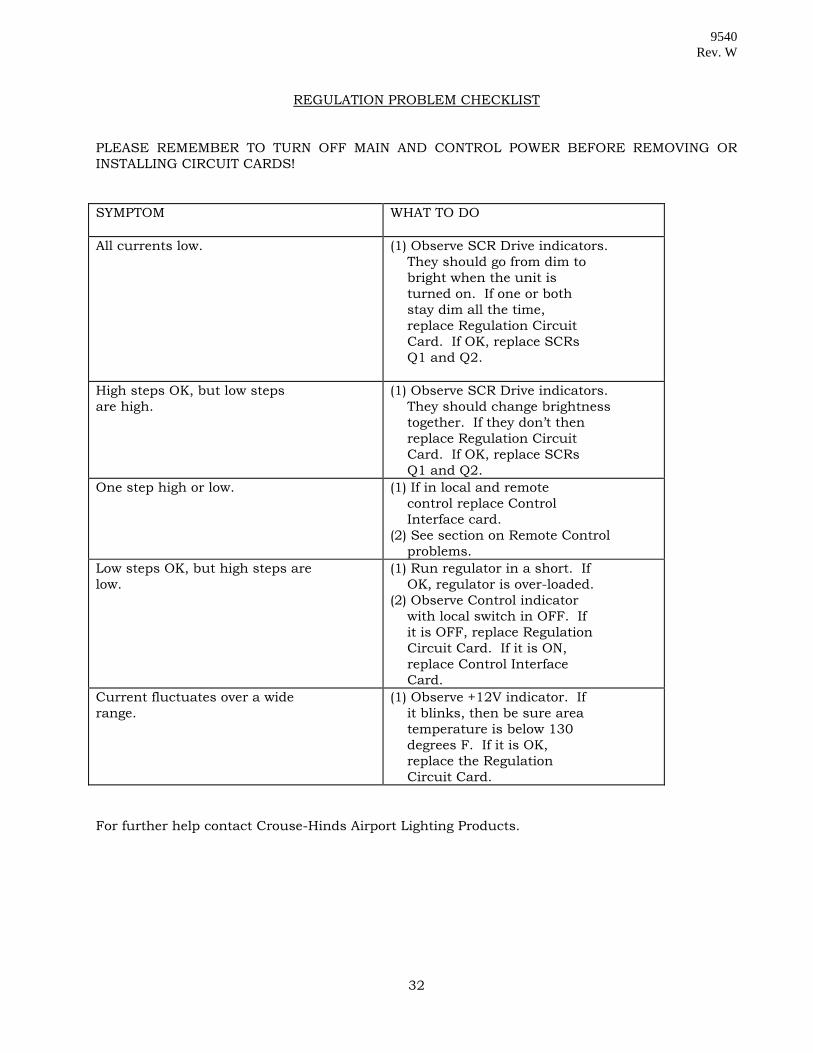
REGULATION PROBLEM CHECKLIST PLEASE REMEMBER TO TURN OFF MAIN AND CONTROL POWER BEFORE REMOVING OR INSTALLING CIRCUIT CARDS! SYMPTOM WHAT TO DO
All currents low. (1) Observe SCR Drive indicators.
They should go from dim to bright when the unit is turned on. If one or both stay dim all the time, replace Regulation Circuit Card. If OK, replace SCRs Q1 and Q2.
High steps OK, but low steps are high.
(1) Observe SCR Drive indicators. They should change brightness together. If they don’t then replace Regulation Circuit Card. If OK, replace SCRs Q1 and Q2.
One step high or low. (1) If in local and remote control replace Control Interface card. (2) See section on Remote Control problems.
Low steps OK, but high steps are low.
(1) Run regulator in a short. If OK, regulator is over-loaded. (2) Observe Control indicator with local switch in OFF. If it is OFF, replace Regulation Circuit Card. If it is ON, replace Control Interface Card.
Current fluctuates over a wide range.
(1) Observe +12V indicator. If it blinks, then be sure area temperature is below 130 degrees F. If it is OK, replace the Regulation Circuit Card.
For further help contact Crouse-Hinds Airport Lighting Products.
32

9540 Rev. W
LOCAL CONTROL PROBLEM CHECKLIST PLEASE REMEMBER TO TURN OFF MAIN AND CONTROL POWER BEFORE REMOVING OR INSTALLING CIRCUIT CARDS! SYMPTOMS WHAT TO DO
System will not turn on. (1) Observe Control and
Contactor indicators. They should go on and off together when switching from off to a step. If they don’t then replace Microcontroller Circuit Card. (2) Check K1 coil for open. If open replace K1. If OK replace Regulation Circuit Card.
System will not turn off. (1) If system will not turn off when the interlock switch is opened, K1 may be welded closed. (2) Observe Contactor indicator. If on all the time, replace Microcontroller Circuit Card. If it turns off, replace Control Interface Card.
Keypad does not respond to one or more key presses.
(1) Check for damage to keypad. If found, replace. (2) Replace display card.
For further help contact Crouse-Hinds Airport Lighting Products.
33

9540 Rev. W
REMOTE CONTROL PROBLEM CHECKLIST PLEASE REMEMBER TO TURN OFF MAIN AND CONTROL POWER BEFORE REMOVING OR INSTALLING CIRCUIT CARDS! SYMPTOM WHAT TO DO
System will not turn on. (1) Check in local control. If
not OK, see section on local control problems. (2) Check remote supply and wiring. If OK, replace Control Interface Card.
System will not turn off. (1) Check for control lines longer than 10,000 feet in length.
Current fluctuates up or down. (1) Check for control lines longer than 10,000 feet in length.
For further help contact Crouse-Hinds Airport Lighting Products
34

9540 Rev. W
DIGITAL PROBLEM CHECKLIST PLEASE REMEMBER TO TURN OFF MAIN AN CONTROL POWER BEFORE REMOVING OR INSTALLING CIRCUIT CARDS! SYMPTOM WHAT TO DO
System will not turn on. (1) Observe Run and Halt
indicators. If they are blinking, replace Regulation Circuit Card. If the Half indicator is always on, replace Microcontroller Circuit Card. If the Run indicator is on all the time, see the section on local control problems.
For further help contact Crouse-Hinds Airport Lighting Products.
MONITOR PROBLEM CHECKLIST (L-829 ONLY) SYMPTOM WHAT TO DO
Remote indicators out. (1) Check for power source on.
(2) Check fuses on load monitor board. (3) If relay indicators on monitor board switch on and off, replace K1, K2 and/or K3. (4) Replace load monitor board.
Unit will not calibrate. (1) Try percent mode calibration (2) Replace load monitor board. (3) Replace transformer T5.
Erroneous readings or alarms. (1) Re-calibrate. (2) Replace load monitor board.
For further help contact Crouse-Hinds Airport Lighting Products.
35

9540 Rev. W
DISPLAY PROBLEM CHECKLIST PLEASE REMEMBER TO TURN OFF MAIN AND CONTROL POWER BEFORE REMOVING OR INSTALLING CIRCUIT CARDS! SYMPTOM WHAT TO DO
Regulator runs but no display. (1) Check for a loose cable from
the display to the Control Interface Card. If OK replace Display Card.
Regulator runs but Display shows wrong current.
(1) Check switch settings on the Control Interface Card. (2) Replace Control Interface Card.
(1) If display reads ‘VER.X.X.’ and does not change, see the section on digital problems. (2) Replace Microcontroller Circuit Card.
For further help contact Crouse-Hinds Airport Lighting Products.
36

9540 Rev. W
37

9540 Rev. W
38

9540 Rev. W
38.1

9540 Rev. W
39

9540 Rev. W
39.1
9540 Rev. W
40

9540 Rev. W
40.1

9540 Rev. W
41
9540 Rev. W
5.1 SCOPE
The Parts List provides ordering data for all replaceable parts and subassemblies.
5.2 ARRANGEMENT
The Figures and Tables in this section are arranged to show each replaceable part or assembly. The parts are identified in each Figure by Index Number. The Index Number appears in the corresponding Parts List which also provides the part number and description.
5.3 REFERENCE DESIGNATION
A reference designation number is assigned to each electrical part contained in the regulator. These reference designations are shown on the wiring diagram.
5.4 OPTION PARTS
Parts that are option related are discussed in the respective Supplement for that Option.
42

9540 Rev. W
43

9540 Rev. W
44

9540 Rev. W

9540 Rev. W
45

9540 Rev. W
46
9540 Rev. W
47

9540 Rev. W
48

9540 Rev. W
49

9540 Rev. W
50

9540 Rev. W
RECOMMENDED SPARES DESCRIPTION PART NUMBER NUMBER REQUIRED Interlock Safety Switch 10047-1878 1 Fuse, 1 amp, Slo-Blo 10047-1205 5 Fuse, 1/8 amp, Slo-Blo 10047-1005 5 Fuse, 2 amp, Slo-Blo 10047-1141 5 SCR/Heatsink Assembly 31505-1 2 (10, 15 & 20 KW) SCR/Heatsink Assembly 31505-2 2 (30 KW) Controller Assembly SEE ITEM 28 DESCRIPTION * *Minimum of one. Consider having 1 controller for every ten CCRS.
51

INDEX NO.
REFERENCE DESIGNATION
DESCRIPTION CROUSE-HINDS AIRPORT LIGHTING PART NO.
MANUFACTURER PART NO.
1
Panel, High Voltage
31544
2
3
Panel, H.V. Switch
31501
4
Panel, Heatsink/SCR
31489
5
6
RI
Resistor Assembly
31499
7
P1
Connector Assembly
32054
8
TB1
Terminal Block Assembly
32048
9
Label, Indicator Light
31683
10
C2
Capacitor
10047-1051
C.S.I. P/N 2N256T
11
S2
Interlock Safety Switch
10047-1878
Unimax P/N 23TL6-4 or equal
12
Standoff, 3/4” Dia.
10053-10
H.H. Smith #2615 or equal
13
DS1
Neon Indicator
10047-938
Lee Craft R2911-T
60 HZ PARTS
9540 R
ev. W
52

INDEX NO.
REFERENCE DESIGNATION
DESCRIPTION CROUSE-HINDS AIRPORT LIGHTING PART NO.
MANUFACTURER PART NO.
14
Fuse Holder
10047-1660
Buss P/N HKP-HH Littlefuse P/N 342858
15
F1 (208, 220, 240, 480V – 10, 15, 20KW; 480V – 30KW
Fuse, 1 amp, Slo-Blo
10047-1205
Buss P/N MDL-1 Littlefuse P/N 313001
F1 (208, 220, 240V – 30KW; 2400V – ALL KW)
Fuse, 2 amp, Slo-Blo
10047-1141
Buss P/N MDL-2 Littlefuse P/N 313002
16
F2
Fuse, 1/8 amp, Slo-Blo
10047-1005
Buss P/N MDL-1/8
17
Standoff Insulator
10053-696
Glastic P/N 1603-1D
Standoff Insulator (2400V)
10053-698
Glastic P/N 1872-1A
18
Wiring Diagram
32055
19
RV2 (ALL VERSIONS EXCEPT 30KW, 208 & 220V) RV3 (ALL VERSIONS)
Varistor, 150V RMS, 20J
10047-1297
G.E. P/N V150LA20B
19
RV2 (30KW, 208 & 220V)
Varistor Assembly
32605
20
Q1 & Q2 (10, 15 & 20KW)
SCR/Heatsink Assembly
31505-1
Q1 & Q2 (30KW)
SCR/Heatsink Assembly
31505-2
21
T3 (208, 220, 240V – 10,15, 20KW; 480V ALL KW)
Transformer
31675
(2400V – ALL KW)
Transformer
32414
(208V – 30KW)
Transformer
10047-2424
ACME P/N TA-2-81305 or TB-81305
(220, 240V – 30KW)
Transformer
10047-1444
ACME P/N TA-2-81213 OR TB-81213
60 HZ PARTS
9540 R
EV. W
53

INDEX NO.
REFERENCE DESIGNATION
DESCRIPTION CROUSE-HINDS AIRPORT LIGHTING PART NO.
MANUFACTURER PART NO.
22
T2 (6.6A)
Current Transformer 31374
T2 (30 KW, 6.6A units only)
Current Transformer
32270
T2 (20A)
Current Transformer
31394
23
C1 (10KW)
Capacitor (not field replaceable)
30062-01
C1 (15KW)
Capacitor (not field replaceable)
30062-04
C1 (20KW)
Capacitor (not field replaceable)
30062-02
C1 (30KW)
Capacitor (not field replaceable)
30062-03
24
LA2 & LA3
Lightning Arrestor, 3KV (10KW; 15KW; 20KW, 20A; 30KW, 20A)
10053-693
G.E. P/N 9L23BXX003XH or Cooper Power AZLP19B3
LA2 & LA3
Lightning Arrestor, 6KV (20KW, 6.6A; 30KW, 6.6A)
10053-351
G.E. P/N 9L23BXX006XH or Cooper Power AZLP19B6
LA1A (2400V)
Lightning Arrestor, 6KV (all KW sizes)
10053-351
25
LA1 (208-480V)
Lightning Arrestor
10047-885
G.E. P/N 9L15ECB001
26
K1 (2400V – ALL KW)
Relay, 160A, Single Pole
10047-2757
Joslyn Clark P/N VC77U01436-76
60 HZ PARTS
9540
REV
. W
54
INDEX NO.
REFERENCE DESIGNATION
DESCRIPTION CROUSE-HINDS AIRPORT LIGHTING PART NO.
MANUFACTURER PART NO.
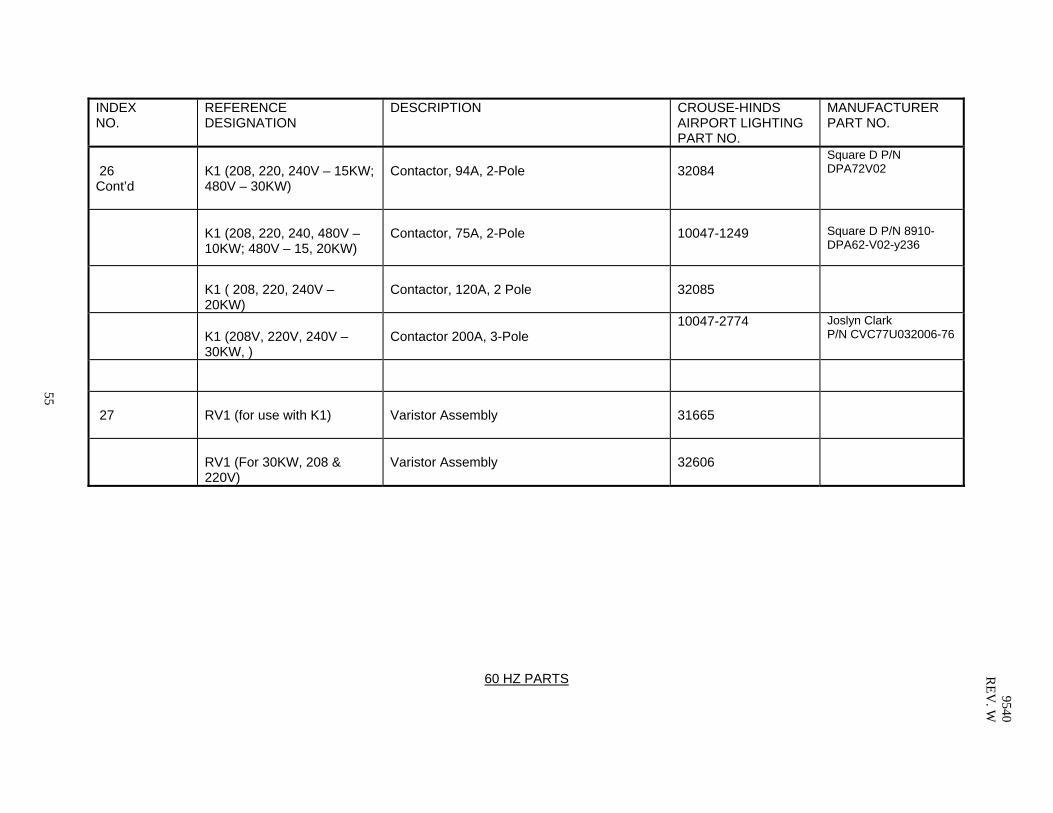
26 Cont’d
K1 (208, 220, 240V – 15KW; 480V – 30KW)
Contactor, 94A, 2-Pole
32084
Square D P/N DPA72V02
K1 (208, 220, 240, 480V – 10KW; 480V – 15, 20KW)
Contactor, 75A, 2-Pole
10047-1249
Square D P/N 8910-DPA62-V02-y236
K1 ( 208, 220, 240V – 20KW)
Contactor, 120A, 2 Pole
32085
K1 (208V, 220V, 240V – 30KW, )
Contactor 200A, 3-Pole
10047-2774 Joslyn Clark P/N CVC77U032006-76
27
RV1 (for use with K1)
Varistor Assembly
31665
RV1 (For 30KW, 208 & 220V)
Varistor Assembly
32606
60 HZ PARTS 9540
REV
. W
55

INDEX NO.
REFERENCE DESIGNATION
DESCRIPTION CROUSE-HINDS AIRPORT LIGHTING PART NO.
MANUFACTURER PART NO.
28
Control Assembly (insert 1, 3 or 5 in place of “X” for number of steps desired. Insert 1 for 6.6A and 2 for 20A in place of “Y” for current desired *(2) The standard Control Assembly consists of the following major replaceable items: Keyboard/Display Card Power Supply Board Assembly Control Interface Board Assembly *(1) Microcontroller Board Assembly Regulation Board Assembly Load Monitor Board Assembly *(2) (L-829 only) Keyboard, 4 x 4 Matrix *(1) If complete control assembly not ordered, set DIP switch on board per instructions. *(2) Specify KW rating of regulator when ordering
32323 ADD -61 at end for L-829 31765-1 31971 31716-1 32277-1 31879-3L 31926-1 10047-2176
60 HZ PARTS
9540 R
EV. W
56

INDEX NO.
REFERENCE DESIGNATION
DESCRIPTION CROUSE-HINDS AIRPORT LIGHTING PART NO.
MANUFACTURER PART NO.
29 T1 Main X’fmr Assy, 10 KW, 6.6A, 208V 31634-10-1 Main X’fmr Assy, 10 KW, 6.6A, 220V 31634-10-2 Main X’fmr Assy, 10 KW, 6.6A, 240V 31634-10-4 Main X’fmr Assy, 10 KW, 6.6A, 480V 31634-10-8 Main X’fmr Assy, 10 KW, 6.6A, 2400V 31634-10-9 Main X’fmr Assy, 15 KW, 6.6A, 208V 31634-15-1 Main X’fmr Assy, 15 KW, 6.6A, 220V 31634-15-2 Main X’fmr Assy, 15 KW, 6.6A, 240V 31634-15-4 Main X’fmr Assy, 15 KW, 6.6A, 480V 31634-15-8 Main X’fmr Assy, 15 KW, 6.6A,2400V 31634-15-9 Main X’fmr Assy, 20 KW, 6.6A, 208V 31634-20-1 Main X’fmr Assy, 20 KW, 6.6A, 220V 31634-20-2 Main X’fmr Assy, 20 KW, 6.6A, 240V 31634-20-4 Main X’fmr Assy, 20 KW, 6.6A, 480V 31634-20-8 Main X’fmr Assy, 20 KW, 6.6A,2400V 31634-20-9 Main X’fmr Assy, 30 KW, 6.6A, 208V 31634-30-1 Main X’fmr Assy, 30 KW, 6.6A, 220V 31634-30-2 Main X’fmr Assy, 30 KW, 6.6A, 240V 31634-30-4 Main X’fmr Assy, 30 KW, 6.6A, 480V 31634-30-8 Main X’fmr Assy, 30 KW, 6.6A, 2400V 31634-30-9 Main X’fmr Assy, 15 KW, 20A, 208V 31634-16-1 Main X’fmr Assy, 15 KW, 20A, 220V 31634-16-2 Main X’fmr Assy, 15 KW, 20A, 240V 31634-16-4 Main X’fmr Assy, 15 KW, 20A, 480V 31634-16-8 Main X’fmr Assy, 15 KW, 20A, 2400V 31634-16-9
60 HZ PARTS
57
9540 R
EV. W
INDEX NO.
REFERENCE DESIGNATION
DESCRIPTION CROUSE-HINDS AIRPORT LIGHTING PART NO.
MANUFACTURER PART NO.
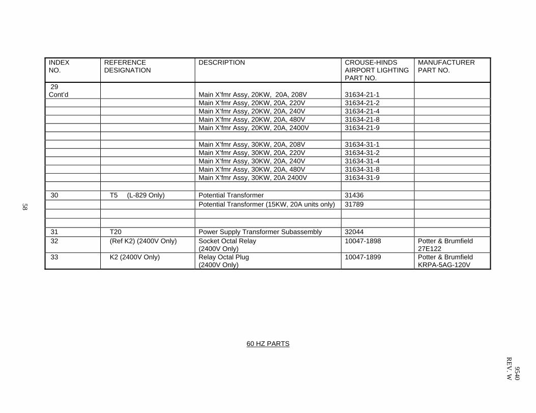
29 Cont’d
Main X’fmr Assy, 20KW, 20A, 208V
31634-21-1
Main X’fmr Assy, 20KW, 20A, 220V 31634-21-2 Main X’fmr Assy, 20KW, 20A, 240V 31634-21-4 Main X’fmr Assy, 20KW, 20A, 480V 31634-21-8 Main X’fmr Assy, 20KW, 20A, 2400V 31634-21-9 Main X’fmr Assy, 30KW, 20A, 208V 31634-31-1 Main X’fmr Assy, 30KW, 20A, 220V 31634-31-2 Main X’fmr Assy, 30KW, 20A, 240V 31634-31-4 Main X’fmr Assy, 30KW, 20A, 480V 31634-31-8 Main X’fmr Assy, 30KW, 20A 2400V 31634-31-9 30 T5 (L-829 Only) Potential Transformer 31436 Potential Transformer (15KW, 20A units only) 31789 31 T20 Power Supply Transformer Subassembly 32044 32 (Ref K2) (2400V Only) Socket Octal Relay
(2400V Only) 10047-1898 Potter & Brumfield
27E122 33 K2 (2400V Only) Relay Octal Plug
(2400V Only) 10047-1899 Potter & Brumfield
KRPA-5AG-120V
60 HZ PARTS
58
9540 R
EV. W

INDEX NO.
REFERENCE DESIGNATION
DESCRIPTION CROUSE-HINDS AIRPORT LIGHTING PART NO.
MANUFACTURER PART NO.
1
Panel, H.V. Input
31544
2
3
Panel, H.V. Switch
31501
4
Panel, Heatsink/SCR
31489
5
6
RI
Resistor Assembly
31499
7
P1
Connector Assembly
32054
8
TB1
Terminal Block Assembly
32048
9
Label, Indicator Light
31683
10
C2
Capacitor
10047-1051
C.S.I. P/N 2N256T
11
S2
Interlock Safety Switch
10047-1878
Unimax P/N 23TL6-4 or equal
12
Standoff, 3/4” Dia.
10053-10
H.H. Smith #2615 or equal
13
DS1
Neon Indicator
10047-938
Lee Craft R2911-T
50 HZ PARTS 9540
REV
. W
59

INDEX NO.
REFERENCE DESIGNATION
DESCRIPTION CROUSE-HINDS AIRPORT LIGHTING PART NO.
MANUFACTURER PART NO.
14
Fuse Holder
10047-1660
Buss P/N HKP-HH Littlefuse P/N 342858
15
F1
Fuse, 1 amp, Slo-Blo (10, 15, 20 KW All; 380, 400, 415 – 30KW)
10047-1205
Buss P/N MDL-1 Littlefuse P/N 313001
F1
Fuse, 2 amp, Slo-Blo (208, 220, 230, 240v – 30KW)
10047-1141
Buss P/N MDL-2 Littlefuse P/N 313002
16
F2
Fuse, 1/8 amp, Slo-Blo
10047-1005
Buss P/N MDL-1/8
17
Standoff Insulator
10053-696
Glastic P/N 1603-1D
18
Wiring Diagram
32055
19
RV2 (ALL VERSIONS EXCEPT 30KW, 208 & 220V) RV3 (ALL VERSIONS)
Varistor, 150V RMS, 20J
10047-1297
G.E. P/N V150LA20B
19
RV2 (30KW, 208 & 220V)
Varistor Assembly
32605
20
Q1 & Q2 (10, 15 & 20KW)
SCR/Heatsink Assembly
31505-1
Q1 & Q2 (30KW)
SCR/Heatsink Assembly
31505-2
21
T3 (10, 15, 20KW All; 380V, 400V, 415V – 30KW)
Transformer
31675
(208V – 30KW)
Transformer
10047-2424
Acme P/N TA-2-81305 or TB-81305
(220V, 230V, 240V – 30KW))
Transformer
10047-1444
Acme P/N TA-2-81213 OR TB-81213
50 HZ PARTS
9540 R
EV. W
60

INDEX NO.
REFERENCE DESIGNATION
DESCRIPTION CROUSE-HINDS AIRPORT LIGHTING PART NO.
MANUFACTURER PART NO.
22
T2 (6.6A)
Current Transformer
31374
T2 (30KW, 6.6A units only)
Current Transformer
32270
T2 (20A)
Current Transformer
31394
23
C1 (10KW)
Capacitor (not field replaceable)
30062-04
C1 (15KW)
Capacitor (not field replaceable)
30062-05
C1 (20KW)
Capacitor (not field replaceable)
30062-05
C1 (30KW)
Capacitor (not field replaceable)
30062-01 30062-03 or (2) 30062-02
24
LA2 & LA3
Lightning Arrestor, 3KV (10KW; 15KW; 20KW, 20A; 30KW, 20A)
10053-693
G.E. P/N 9L23BXX003XH or Cooper Power AZLP19B3
LA2 & LA3
Lightning Arrestor, 6KV (20KW, 6.6A; 30KW, 6.6A)
10053-351
G.E. P/N 9L23BXX006XH or Cooper Power AZLP19B6
25
LA1 (208-415V)
Lightning Arrestor
10047-885
G.E. P/N 9L15ECB001
50 HZ PARTS
9540 R
EV. W
61
INDEX NO.
REFERENCE DESIGNATION
DESCRIPTION CROUSE-HINDS AIRPORT LIGHTING PART NO.
MANUFACTURER PART NO.
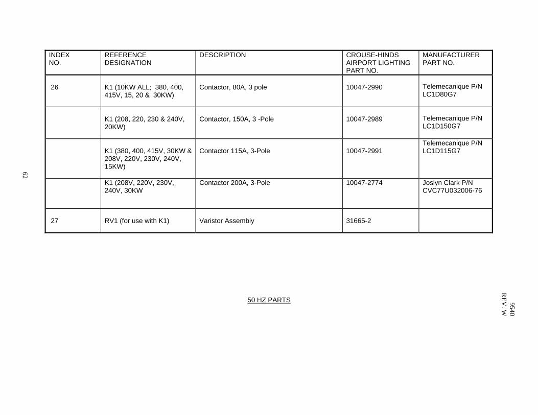
26
K1 (10KW ALL; 380, 400, 415V, 15, 20 & 30KW)
Contactor, 80A, 3 pole
10047-2990
Telemecanique P/N LC1D80G7
K1 (208, 220, 230 & 240V, 20KW)
Contactor, 150A, 3 -Pole
10047-2989
Telemecanique P/N LC1D150G7
K1 (380, 400, 415V, 30KW & 208V, 220V, 230V, 240V, 15KW)
Contactor 115A, 3-Pole
10047-2991
Telemecanique P/N LC1D115G7
K1 (208V, 220V, 230V, 240V, 30KW
Contactor 200A, 3-Pole 10047-2774 Joslyn Clark P/N CVC77U032006-76
27
RV1 (for use with K1)
Varistor Assembly
31665-2
50 HZ PARTS
9540 R
EV. W
62

28
Control Assembly (insert 1, 3 or 5 in place of “X” for number of steps desired. Insert 1 for 6.6A and 2 for 20A in place of “Y” for current desired *(2) The standard Control Assembly consists of the following major replaceable items: Keyboard/Display Card Power Supply Board Assembly Control Interface Board Assembly *(1) Microcontroller Board Assembly Regulation Board Assembly Load Monitor Board Assembly *(2) (L-829 only) Keyboard, 4 x 4 Matrix *(1) If complete control assembly not ordered, set DIP switch on board per instructions. *(2) Specify KW rating of regulator when ordering
32323- ADD -61 at end for L-829 31765-1 31971 31716-1 32277-1 31879-3L 31926-1 10047-2176
50 HZ PARTS
9540 R
EV. W
63

INDEX NO.
REFERENCE DESIGNATION
DESCRIPTION CROUSE-HINDS AIRPORT LIGHTING PART NO.
MANUFACTURER PART NO.
29 T1 Main X’fmr Assy, 10 KW, 6.6A, 208V 31635-10-1 Main X’fmr Assy, 10 KW, 6.6A, 220V 31635-10-2 Main X’fmr Assy, 10 KW, 6.6A, 230V 31635-10-3 Main X’fmr Assy, 10 KW, 6.6A, 240V 31635-10-4 Main X’fmr Assy, 10 KW, 6.6A, 380V 31635-10-5 Main X’fmr Assy, 10 KW, 6.6A, 400V 31635-10-6 Main X’fmr Assy, 10 KW, 6.6A, 415V 31635-10-7 Main X’fmr Assy, 15 KW, 6.6A, 208V 31635-15-1 Main X’fmr Assy, 15 KW, 6.6A, 220V 31635-15-2 Main X’fmr Assy, 15 KW, 6.6A, 230V 31635-15-3 Main X’fmr Assy, 15 KW, 6.6A, 240V 31635-15-4 Main X’fmr Assy, 15 KW, 6.6A, 380V 31635-15-5 Main X’fmr Assy, 15 KW, 6.6A, 400V 31635-15-6 Main X’fmr Assy, 15 KW, 6.6A, 415V 31635-15-7 Main X’fmr Assy, 20 KW, 6.6A, 208V 31635-20-1 Main X’fmr Assy, 20 KW, 6.6A, 220V 31635-20-2 Main X’fmr Assy, 20 KW, 6.6A, 230V 31635-20-3 Main X’fmr Assy, 20 KW, 6.6A, 240V 31635-20-4 Main X’fmr Assy, 20 KW, 6.6A, 380V 31635-20-5 Main X’fmr Assy, 20 KW, 6.6A, 400V 31635-20-6 Main X’fmr Assy, 20 KW, 6.6A, 415V 31635-20-7 Main X’fmr Assy, 30 KW, 6.6A, 208V 31635-30-1 Main X’fmr Assy, 30 KW, 6.6A, 220V 31635-30-2 Main X’fmr Assy, 30 KW, 6.6A, 230V 31635-30-3 Main X’fmr Assy, 30 KW, 6.6A, 240V 31635-30-4 Main X’fmr Assy, 30 KW, 6.6A, 380V 31635-30-5 Main X’fmr Assy, 30KW, 6.6A, 400V 31635-30-6 Main X’fmr Assy, 30KW, 6.6A, 415V 31635-30-7
50 HZ PARTS
9540 R
EV. W
64

INDEX NO.
REFERENCE DESIGNATION
DESCRIPTION CROUSE-HINDS AIRPORT LIGHTING PART NO.
MANUFACTURER PART NO.
29 Cont’d
Main X’fmr Assy, 15 KW, 20A, 208V 31635-16-1 Main X’fmr Assy, 15 KW, 20A, 220V 31635-16-2 Main X’fmr Assy, 15 KW, 20A, 230V 31635-16-3 Main X’fmr Assy, 15 KW, 20A, 240V 31635-16-4 Main X’fmr Assy, 15 KW, 20A, 380V 31635-16-5 Main X’fmr Assy, 15 KW, 20A, 400V 31635-16-6 Main X’fmr Assy, 15 KW, 20A, 415V 31635-16-7
50 HZ PARTS
9540 R
EV. W
65

INDEX NO.
REFERENCE DESIGNATION
DESCRIPTION CROUSE-HINDS AIRPORT LIGHTING PART NO.
MANUFACTURER PART NO.
29 Cont’d
Main X’fmr Assy, 20 KW, 20A, 208V
31635-21-1
Main X’fmr Assy, 20 KW, 20A, 220V 31635-21-2 Main X’fmr Assy, 20 KW, 20A, 230V 31635-21-3 Main X’fmr Assy, 20 KW, 20A, 240V 31635-21-4 Main X’fmr Assy, 20 KW, 20A, 380V 31635-21-5 Main X’fmr Assy, 20 KW, 20A, 400V 31635-21-6 Main X’fmr Assy, 20 KW, 20A, 415V 31635-21-7 Main X’fmr Assy, 30 KW, 20A, 208V 31635-31-1 Main X’fmr Assy, 30 KW, 20A, 220V 31635-31-2 Main X’fmr Assy, 30 KW, 20A, 230V 31635-31-3 Main X’fmr Assy, 30 KW, 20A, 240V 31635-31-4 Main X’fmr Assy, 30 KW, 20A, 380V 31635-31-5 Main X’fmr Assy, 30 KW, 20A, 400V 31635-31-6 Main X’fmr Assy, 30 KW, 20A, 415V 31635-31-7 NOTE: Main X’fmr Assy P/N includes
capacitor (C1) and transformer (T2)
30 T5 (L-829 Only) Potential Transformer 31436 Potential Transformer (15KW, 20A units only) 31789 31 T20 Power Supply Transformer Subassembly 32044 32
33
50 HZ PARTS 9540
REV
. W
66