Embed Size (px)
Citation preview

TITLE “Mixing Technology”
SPEAKER: Mr. Jan Siert Tjeerdsma
JOB TITLE: Sr. Project Manager
DATE : Antwerp, March 20th, 2013
WWW.STOCEXPO.COM
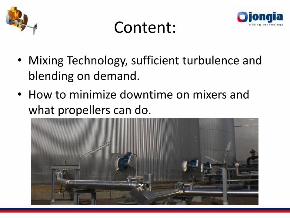
Content:
• Mixing Technology, sufficient turbulence and blending on demand.
• How to minimize downtime on mixers and what propellers can do.
SUBJECT
• Introduction
• Why Mixing ? – Laminar and Turbulent Flow
– Blending time & improvement of heat-transfer
– Mixer positioning
• Common mixer specifications – Mechanical design
– Propeller design
– Process innovation
• Summary
Introduction
• Jan Siert Tjeerdsma
• Bsc Chemical Engineering
• Project Engineer Jongia Mixing Technology
• 18 years experience with Major contractors
• Responsible for projects in Biofuels, Tank Storage farms, Petrochemical & Fine Chemicals
• Linkedin-profile
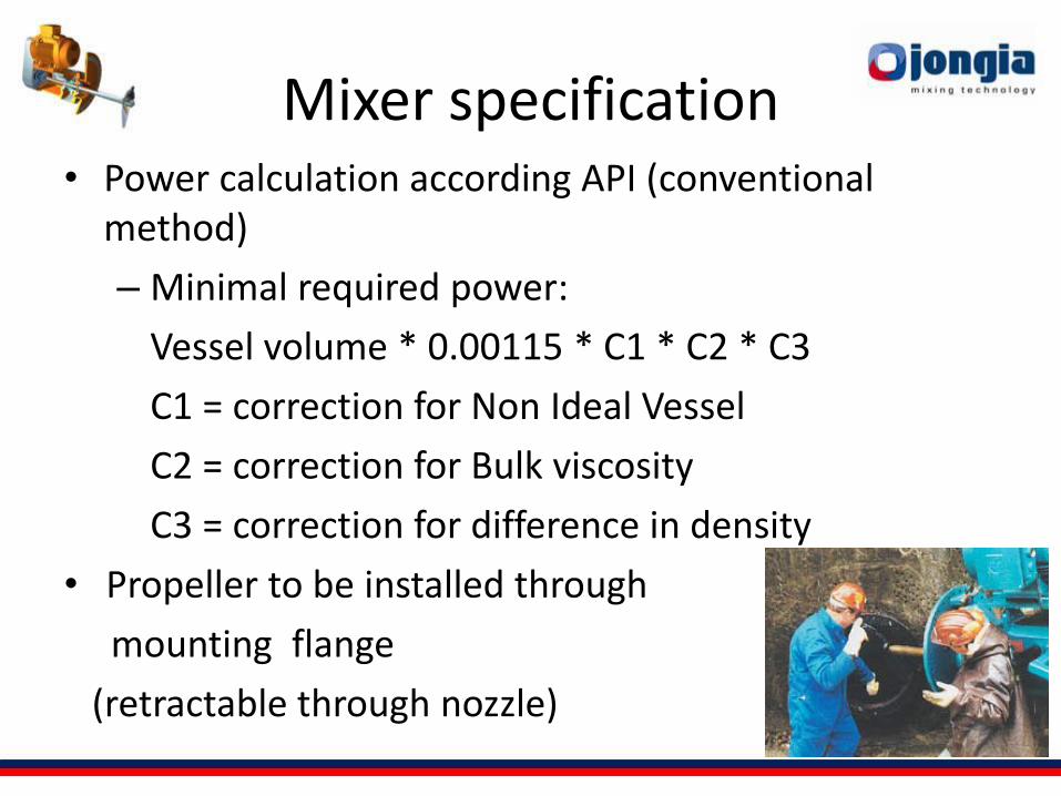
Mixer specification • Power calculation according API (conventional
method)
– Minimal required power:
Vessel volume * 0.00115 * C1 * C2 * C3
C1 = correction for Non Ideal Vessel
C2 = correction for Bulk viscosity
C3 = correction for difference in density
• Propeller to be installed through
mounting flange
(retractable through nozzle)
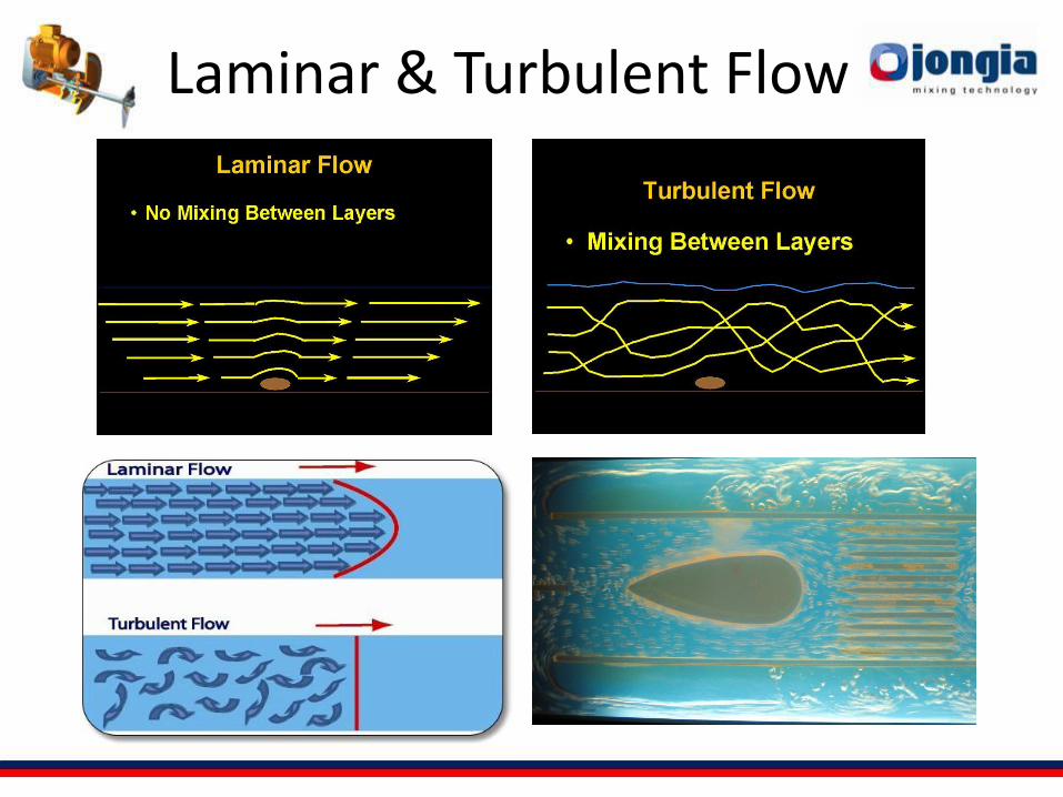
Laminar & Turbulent Flow
Laminar & Turbulent Mixing
• Reynolds < 2000 Laminar flow
• Reynolds 2000 – 3200 Transition region
• Reynolds >3200 Turbulent flow
• Reynolds in mixing depends on: – Liquid density
– Rotational speed of propeller
– Propeller Diameter
– Viscosity of the liquid
– Independent of propeller geometry
Flow in the tank
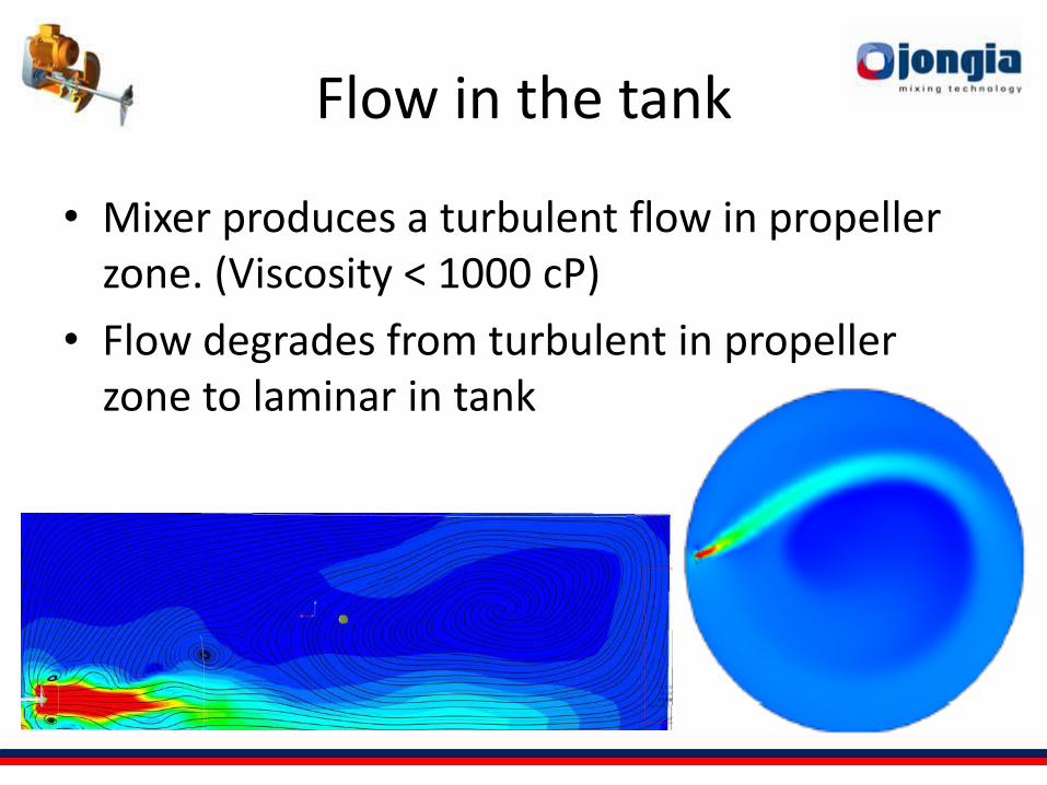
• Mixer produces a turbulent flow in propeller zone. (Viscosity < 1000 cP)
• Flow degrades from turbulent in propeller zone to laminar in tank
Why should we mix in a tank ? • Preventing settling of solids
• Homogenize temperature (Prevent stratification)
• Blending various fluids or fractions
• Prevent emission of volatile components
Why should we NOT? • High power consumption, useless?
• Risk of oilspill
• Maintenance required
• Cost aspect
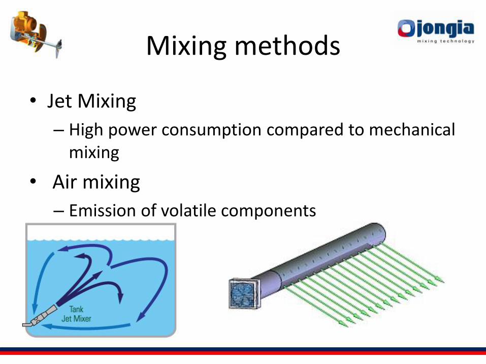
Mixing methods
• Jet Mixing
– High power consumption compared to mechanical mixing
• Air mixing
– Emission of volatile components
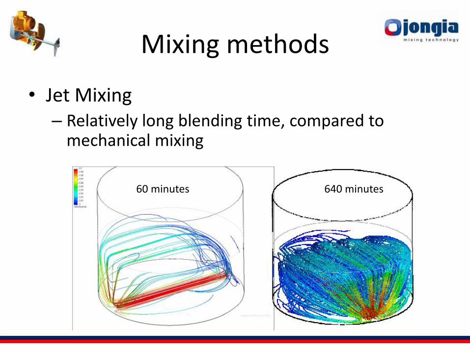
Mixing methods
• Jet Mixing – Relatively long blending time, compared to
mechanical mixing
60 minutes 640 minutes
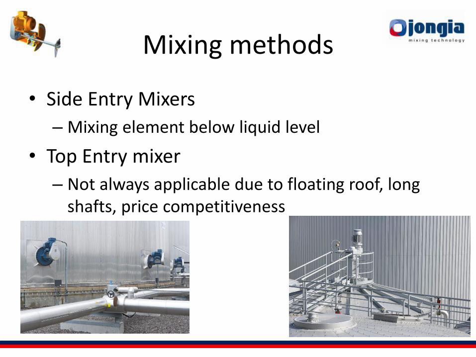
Mixing methods
• Side Entry Mixers
– Mixing element below liquid level
• Top Entry mixer
– Not always applicable due to floating roof, long shafts, price competitiveness
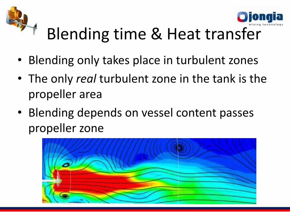
Blending time & Heat transfer
• Blending only takes place in turbulent zones
• The only real turbulent zone in the tank is the propeller area
• Blending depends on vessel content passes propeller zone
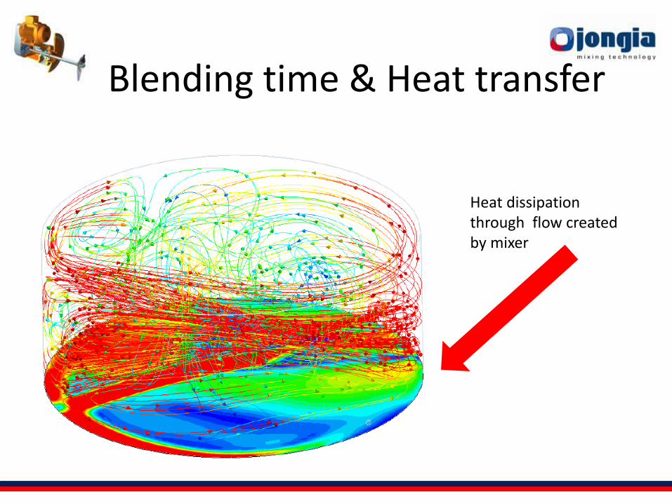
Blending time & Heat transfer
Heat dissipation through flow created by mixer
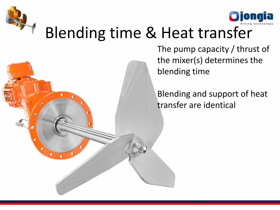
Blending time & Heat transfer The pump capacity / thrust of the mixer(s) determines the blending time Blending and support of heat transfer are identical
Blending time
• Important to specify required blending
• Relation between blending time and power is quadratic
• Blending time is based upon completely topped-up vessel
• Positioning of mixer has a major influence on blend time
• Flow of impeller determines blend time
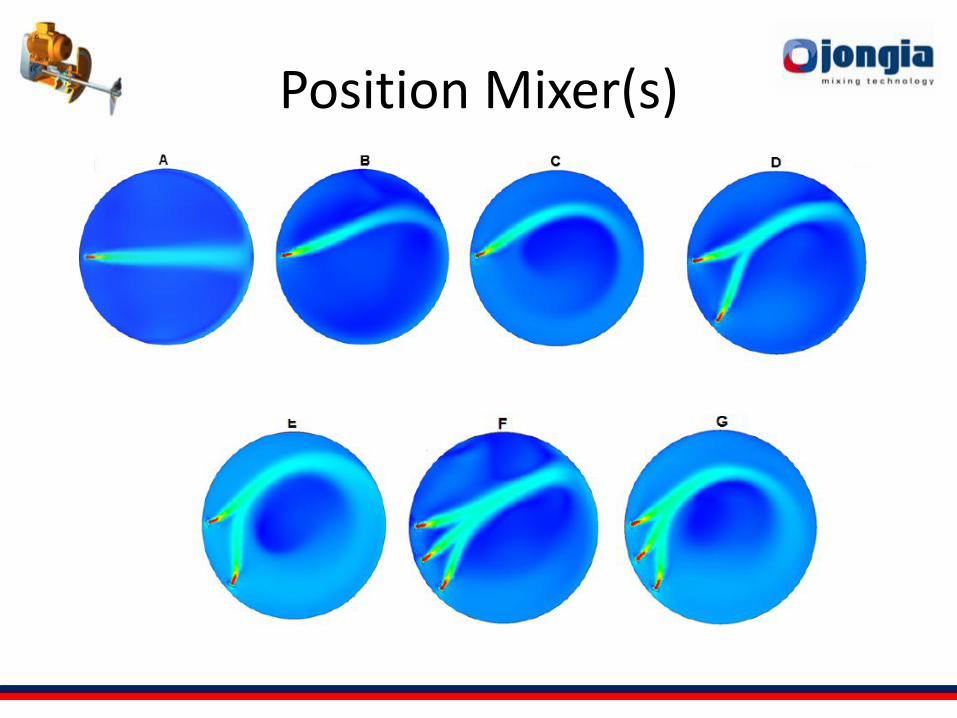
Position Mixer(s)
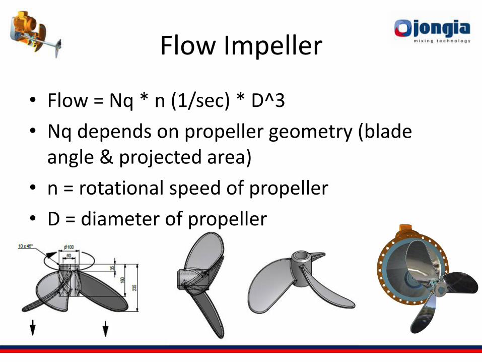
Flow Impeller
• Flow = Nq * n (1/sec) * D^3
• Nq depends on propeller geometry (blade angle & projected area)
• n = rotational speed of propeller
• D = diameter of propeller
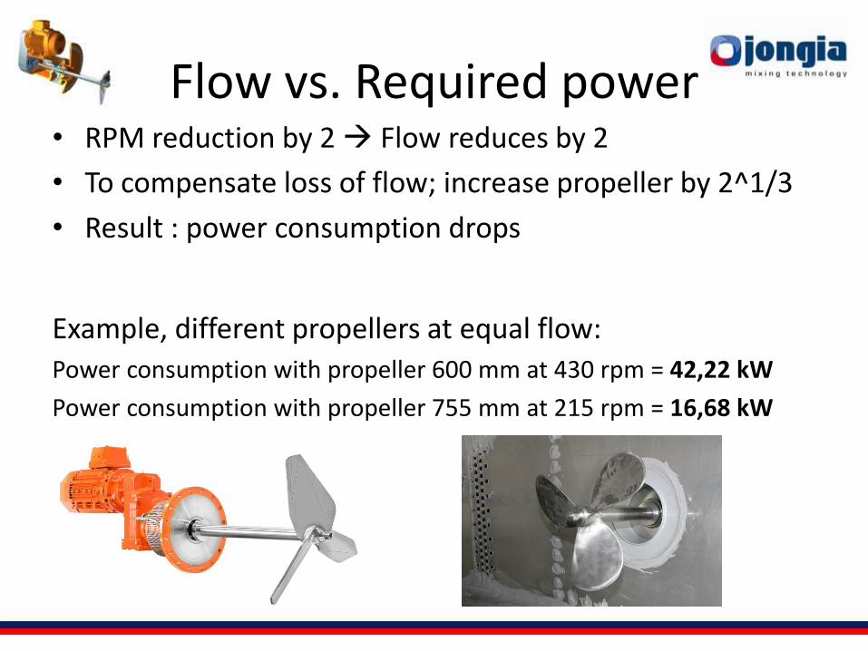
Flow vs. Required power • RPM reduction by 2 Flow reduces by 2
• To compensate loss of flow; increase propeller by 2^1/3
• Result : power consumption drops
Example, different propellers at equal flow:
Power consumption with propeller 600 mm at 430 rpm = 42,22 kW
Power consumption with propeller 755 mm at 215 rpm = 16,68 kW
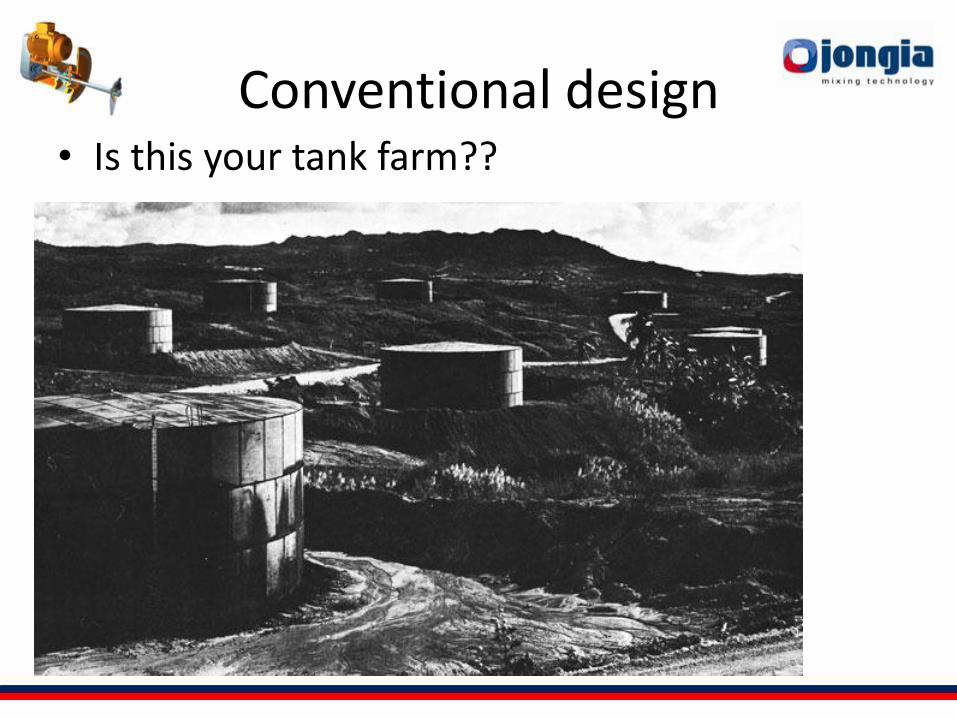
Conventional design • Is this your tank farm??
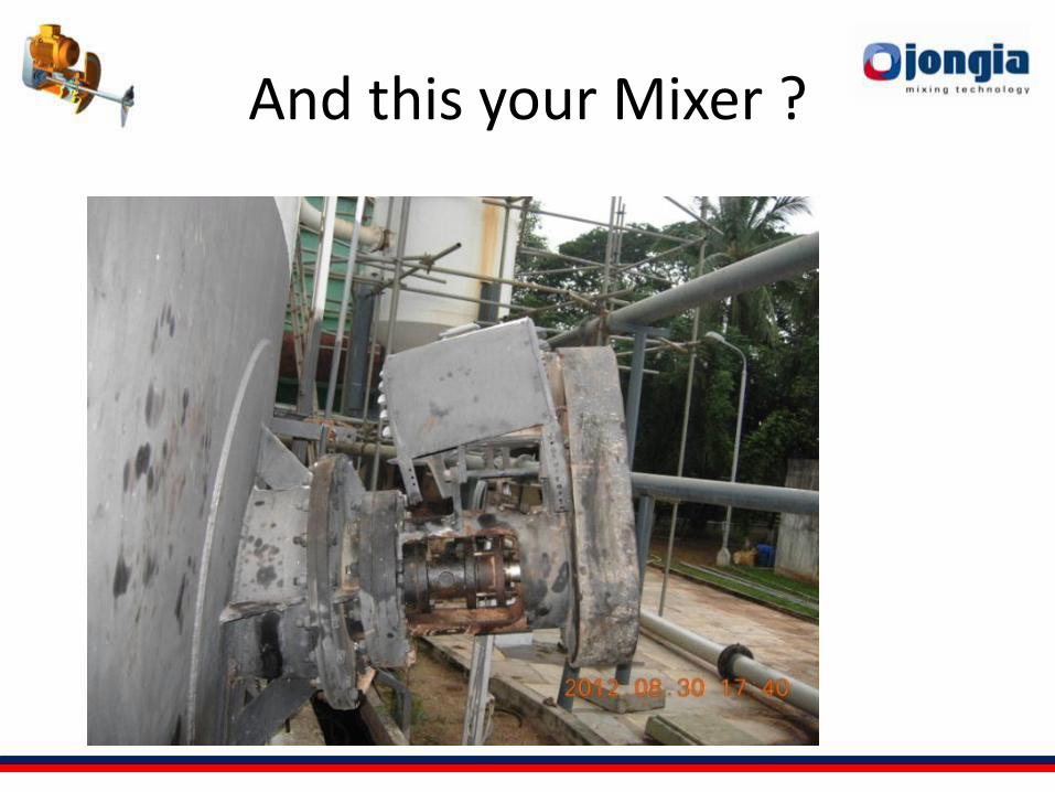
And this your Mixer ?
Consider
• Reliable product
• High efficient thrust
• Easy to maintain
• Versatile commodity parts applied
• Compact and Modular design
• Developed for relability
• The Jongia Sydmikser RWM range!
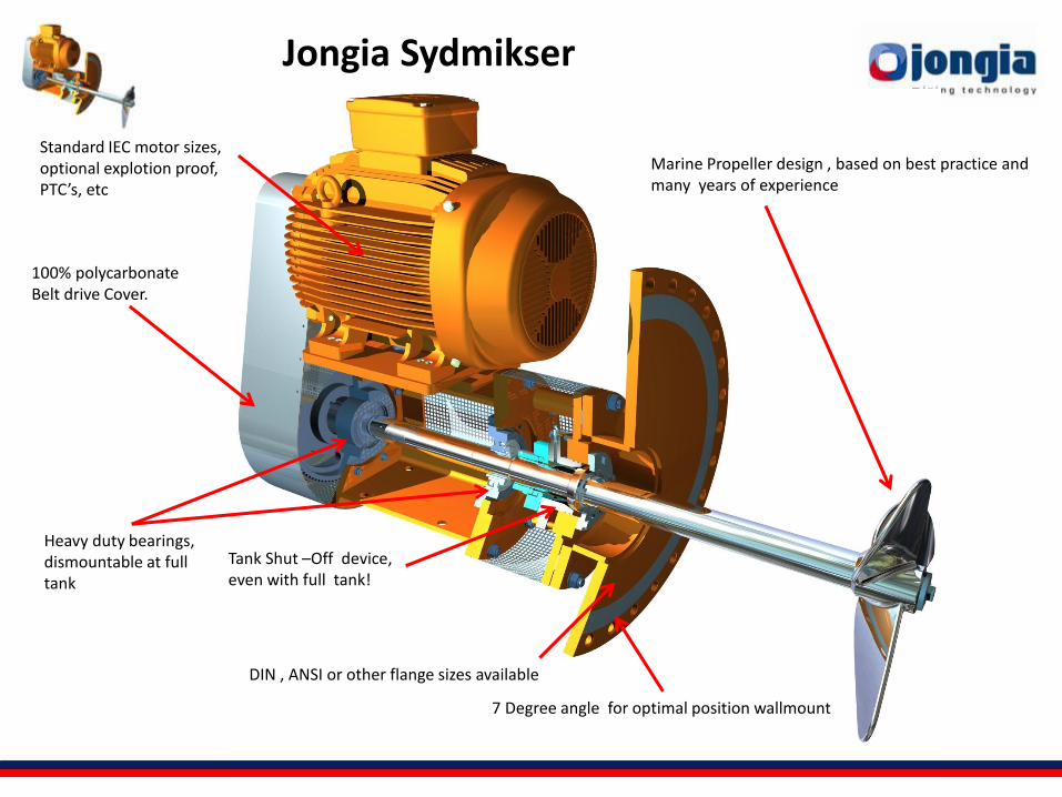
Marine Propeller design , based on best practice and many years of experience
7 Degree angle for optimal position wallmount
Standard IEC motor sizes, optional explotion proof, PTC’s, etc
Heavy duty bearings, dismountable at full tank
DIN , ANSI or other flange sizes available
100% polycarbonate Belt drive Cover.
Tank Shut –Off device, even with full tank!
Jongia Sydmikser
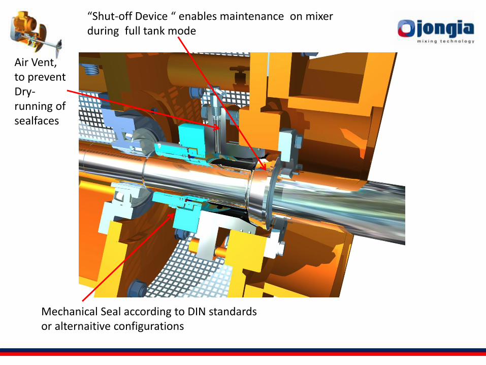
“Shut-off Device “ enables maintenance on mixer during full tank mode
Mechanical Seal according to DIN standards or alternaitive configurations
Air Vent, to prevent Dry-running of sealfaces
WWW.STOCEXPO.COM
See for yourself
It is at our booth # F1
Get your free brochure
Get your Sydmikser RWM from
Jongia Mixing Technology!!
Thank you!