Embed Size (px)
Citation preview

Xraise Outreach for CLASSE 161 Synchrotron Drive, Wilson Lab, Cornell University, Ithaca, NY 14853
xraise.classe.cornell.edu
Title: Stunt Car Challenge!
Original: Revision:
28 October 2007 9 January 2009
Authors: Buzz Putnam
Appropriate Level: High School Physics (New York State Regents-Level)
Abstract: A projectile motion lab is required for the NYS Regents Physics classroom and state standards require a qualitative and quantitative understanding of the horizontal and vertical displacements as a function of launch angle. In a fun and engaging way, students meet these standards with this lab. The lab apparatus consists of a launcher that includes three angle settings and a photogate placed to measure the initial launch velocity of the projectile. In Part I, the lab team will qualitatively experiment with a projectile motion simulation, working through the launch angle vs, dv and dh. In Part II, they calculate their car’s initial velocity from the photogate time and car length. After calculating the horizontal and vertical distances for the different launch angles, the lab team will attempt to hit a landing pad and have their car fly through the dreaded “Ring of Fire.”
Time Required: Two 40 minute class periods
NY Standards Met: The path of a projectile is the result of the simultaneous effect of the horizontal and vertical components of its motion; these components act independently. (5.1f, 5.1i, 5.1ii, 5.1vii)
A projectile's time of flight is dependent upon the vertical components of its motion. (5.1g, 5.1vii)
The horizontal displacement of a projectile is dependent upon the horizontal component of its motion and its time of flight. (5.1h, 5.1vii)
Special Notes: Stunt Car Challenge is a kit available from the CIPT Equipment Lending Library, Xraise.classe.cornell.edu Created by the CNS Institute for Physics Teachers via the Nanoscale Science and Engineering Initiative under NSF Award # EEC-0117770, 0646547 and the NYS Office of Science, Technology & Academic Research under NYSTAR Contract # C020071

Page 2
Teacher Section – Stunt Car Challenge!
Behavioral Objectives: Upon completion of this lab, a student should be able to:
Qualitatively determine the horizontal and vertical displacements through the use of a projectile motion simulation that allows them to vary launch angles.
Conceptually visualize the relationship between the launch angle and the resulting horizontal and vertical displacements.
Quantitatively determine the horizontal and vertical displacements for a project launched with a given angle and velocity.
Class Time Required: For the complete Projectile Motion lab experiment, the students will need a minimum of two-40 minute lab periods or one period if on a “Block” schedule. Teacher Preparation Time Required: Total prep time - ~20 minutes, longer if you are not familiar with the photogates
For Part I, the set-up requires only a computer station and the “PhET simulation” either installed or Internet capability.
For Part II, the teacher must set up the launch apparatus with accompanying photogates.
Teachers must observe heightened awareness of safety throughout this lab. This lab requires the launching of objects at high speeds. Be certain to have supervision and practice safety precautions such as safety glasses at all times.
Materials Needed:
“PhET simulation” available free through…http://phet.colorado.edu/simulations/projectilemotion/projectile.swf
“Jump Track” set-up
Photogates (Vernier, Pasco or Arbor Scientific)
“Darda” toy car (pull-back car)
Fish nets
Protractor/Metric tape measure/meter stick
Carbon paper
Calculators Assumed Prior Knowledge of Students: Very little prior knowledge of projectile motion is required for using the computer simulation in Part I, which is intended to be discovery/inquiry-based activity for exploring the relationship between the launch angle and the resulting horizontal and vertical distances for projectile trajectories in vacuum and air. Part II can only be done after the student is introduced to the following mathematical concepts of projectile motion: determination of the velocity components, the vertical and horizontal times of flight, and the horizontal and vertical distances for the projectile as a function of launch angle.

Page 3
Teacher Section – Stunt Car Challenge!
Background Information for Teacher:
The teacher should have complete conceptual knowledge of qualitative and quantitative determinations of dh, dv and the angle vs. dh and dv relationship. Despite the simulation illustrating the ideal conditions, the teacher should be aware that the application of projectile motion in a real-life situation leads to some deviation from the “perfect” answers that will result in this lab. The “Jump Track” set-up and “Darda” toy car (pull-back car) are affected by friction variables and will not result in true textbook accuracy depending on conditions. Students will ask why the angles are not at higher settings as exhibited in the simulation. Real-life car and motorcycle jumps are accomplished at angles less than 30 degrees. Remember that each set-up may vary in its launch velocities and a number of experimental trials will result in truer calculations.
The crucial point of this lab is the set-up of the photogate at the end of the track. The photogate determines the time the entire car passes through its detectors. Numerous photogate set-ups have been tested and manipulated at Cornell to achieve the highest degree of precision in measuring the car’s velocity at its take-off point. Be certain that the photogate is placed as seen in the attached photo at the end of this lab. Through trials at CIPT, it was found that vertically-arranged photogates provide the best measurements for the car’s velocity leaving the track. Photogates can also be set-up on ring stands prior to the students’ experiments if the teacher prefers, but pre-test all set-ups prior to the lab.
The “Stunt Car Track” set-up has been designed to accept most photogate types. Each type of photogate MUST be arranged vertically in order to clearly detect the length of the car. Horizontally mounted photogates are too inconsistent in their readings, consequently causing the data/calculation of the car’s initial velocity to render the lab conclusions vague and meaningless. The track has adaptations for Arbor Scientific and Vernier/Pasco photogates. (See included schematic of the track assembly.)
If using Vernier Photogates:
For the Vernier photogates, you will need a Vernier LabQuest or a Vernier LabPro.
Attach the patch cord from the photogate to the LabQuest or LabPro and plug the power cord.
Turn on your LabQuest/LabPro and this will activate the photogate.
The measurement read by the LabQuest is the total time the photogate is blocked by the car.
Before you launch your car, your partner must prepare to catch the car as it leaves the ramp using the fish net.
The Vernier photogate timer will record the time that the entire toy car body passes through the photogate.
The resulting velocity of the car can be found by calculating the length of the toy car divided by the time the car takes to pass through the vertically-arranged photogates. v = d/t

Page 4
Teacher Section – Stunt Car Challenge!
If using Arbor Photogates:
Attach a single Photogate to the Arbor Timer.
Screw the Photogate on the track vertically (see diagram) to capture the motion of the car as it passes through. The car will block the light beam as it passes through the gate.
Use the Mode button to choose “Gate Mode.”
Launch the car through the Photogate.
Find the car’s velocity by dividing the car length (the distance traveled) by the measured time (the time it took to travel that short distance).--> v = d/t
The student can view each trial of data collection if they wish by viewing “Memory in One Gate Mode”. Normally all data collected can be viewed by pressing the Memory button to “step” through all data results. When using the One Gate, the timer starts counting when a phototgate is interrupted the first time and continues to count until a second interruption of the photogates occurs. If the timer is in its counting cycle it is not possible to view data in memory. You must either press the reset button to exit the cycle or turn off power to the unit. Directions in using the Arbor Photogate in additional modes can be found at www.arborsci.com or calling 1-800-367-6695.
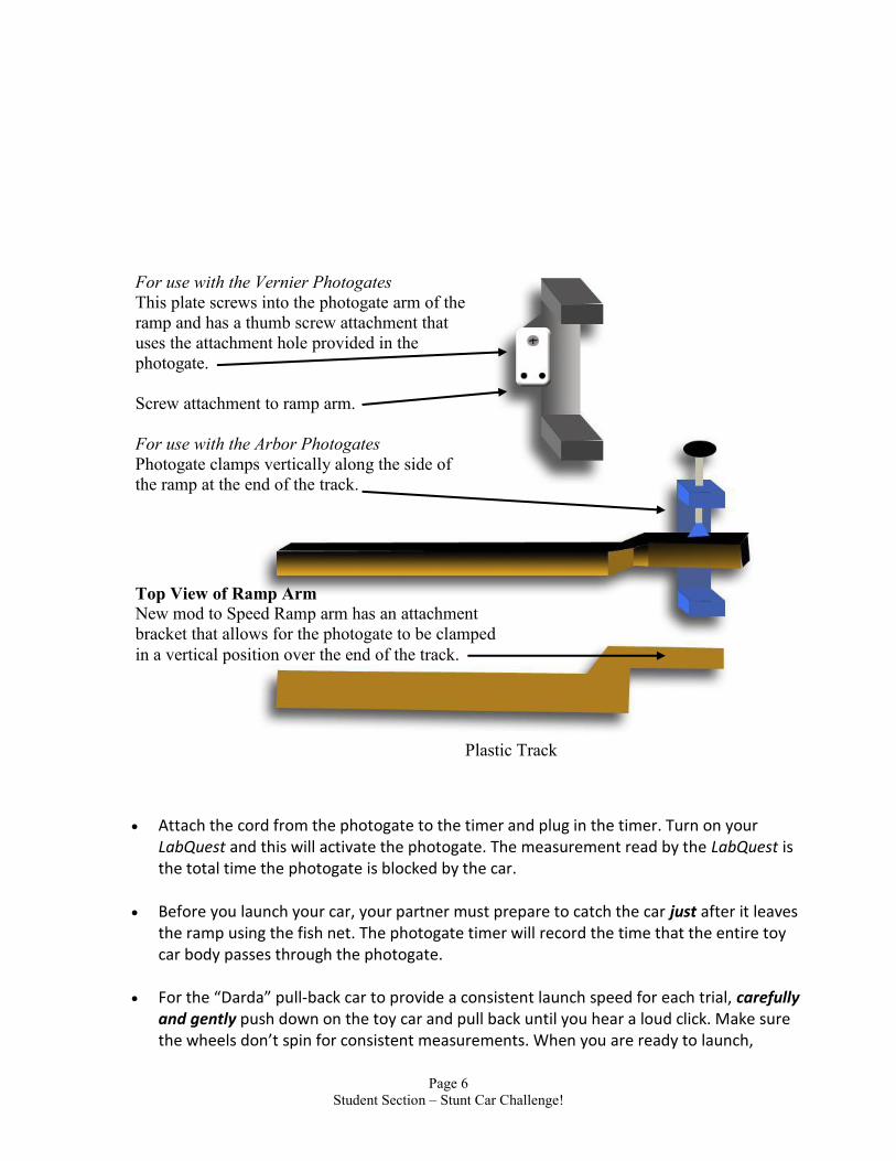
Plastic Track
Top View of Ramp Arm
New mod to Speed Ramp arm has an attachment
bracket that allows for the photogate to be clamped
in a vertical position over the end of the track.
For use with the Vernier Photogates
This plate screws into the photogate arm of the
ramp and has a thumb screw attachment that
uses the attachment hole provided in the
photogate.
Screw attachment to ramp arm.
For use with the Arbor Photogates
Photogate clamps vertically along the side of
the ramp at the end of the track.

Page 5
Teacher Section – Stunt Car Challenge!
Prior to the students actually launching their cars for this lab, the students are required to calculate the Horizontal Displacement (dh) and the Vertical Displacement (dv) for their individual car/track set-up. The cars’ velocities and the track specifications differ slightly for each individual lab set-up, but the results between all lab set-ups are similar, with some slight deviations. Below is a data table of five (5) launched car trials at the 10o, 20o and 30o angles, the velocity of the car as it leaves the ramp, and the resulting dh and dv values. The actual calculations for the horizontal and vertical displacements at the given angles are shown below as a reference for the teacher. The calculation method uses d = vit + ½ at2 for both vertical and horizontal motion. Remember to keep the horizontal and vertical motion calculations of the car during its flight completely independent from each other. The vertical motion of the launched car does not affect the horizontal motion of that same launched car while in flight, no matter what the initial velocity or angle of launch is!
Helpful Equations General Equation for Projectile Motion d = vit + ½ at2
For Vertical Motion only ---------------- dv = vivtv + ½ avtv2
For Horizontal Motion only ------------- dh = vihth + ½ ahth2
For determination for time of flight ------ a = v/t For determining the vertical and horizontal components of the car’s velocity --------- c2 = a2 + b2 Sine, Cosine, Tangent functions
Steps in solving an angled projectile motion problem
Find the vertical (vv) and horizontal (vh) components of the car’s velocity.
Find the time (tv) it takes the car to reach its highest vertical displacement; its “halfway point” during its flight.
Multiply the tv by 2 to find the horizontal time (th).
B using the Velocity data (vv & vh) and the Time data (tv & th), the the Horizontal Displacement and the Vertical Displacement of the launched car can be found.
For finding Vertical Displacements, use the equation, dv = vivtv + ½ avtv2, where…
dv = Vertical Displacement viv = Initial Vertical Velocity tv = Vertical Time av = Vertical Acceleration
For finding Horizontal Displacements, use the equation, dh = vihth + ½ ahth2,
where… dh = Horizontal Displacement vih = Initial Horizontal Velocity th = Horizontal Time ah = Horizontal Acceleration
Remember that the Horizontal Acceleration of a projectile is zero, meaning the object is moving at a constant velocity resulting in zero acceleration of the object (Dynamic Equilibrium).

Page 6
Teacher Section – Stunt Car Challenge!
Sample Calculations
The cars have been tested for their reliability and consistency in launch velocity results. Each car will have its own launch velocity due to the manufacturing of the car’s mechanics, but numerous tests have found the cars’ average launch velocities to be 3.4 m/s. Your individual results will vary with each lab set-up, but for the 3.4 m/s as the Initial Launch Velocity of the car.
The track allows three (3) angle settings for the students in their experiments; 10o, 20o and 30o. The sample calculations for all three angles are shown below. Your students’ calculations will vary from set-up to set-up, with slight variation resulting from friction, car manufacturing, student error and other factors.
Car Launch #1 at 3.4 m/s with 10o
1. Find Vertical Velocity (Vv) Component Sin 10o=Vv/3.4 0.59 m/s 2. Find Horizontal Velocity (Vh) Component Cos 10o=Vv/3.4 3.3 m/s 3. Find the Vertical Time (tv) a = v/t -9.8 m/s2 = 0 m/s – 0.59 m/s 0.060 sec t 4. Find the Horizontal Time (th) 0.060 sec X 2 = 0.12 sec 5. Find Vertical Displacement (dv) dv = vivtv + ½ avtv
2 dv = (0.59 m/s)(0.060 sec) + ½ (-9.8 m/s2)(0.060)2 dv = 0.017m 6. Find Horizontal Displacement (dh) dh = vihth + ½ ahth
2 dh = (3.3 m/s)(0.12 sec) + ½ (0 m/s2)(0.12)2 dh = 0.40m 3.4 m/s Vv = 0.59 m/s 10o Vh = 3.3 m/s Car Launch #2 at 3.4 m/s with 20o
1. Find Vertical Velocity (Vv) Component Sin 20o=Vv/3.4 1.2 m/s 2. Find Horizontal Velocity (Vh) Component Cos 20o=Vv/3.4 3.2 m/s 3. Find the Vertical Time (tv) a = v/t -9.8 m/s2 = 0 m/s – 1.2 m/s 0.12 sec t 4. Find the Horizontal Time (th) 0.12 sec X 2 = 0.24 sec 5. Find Vertical Displacement (dv) dv = vivtv + ½ avtv
2 dv = (1.2 m/s)(0.12 sec) + ½ (-9.8 m/s2)(0.12)2 dv = 0.073m 6. Find Horizontal Displacement (dh) dh = vihth + ½ ahth
2 dh = (3.2 m/s)(0.24 sec) + ½ (0 m/s2)(0.24)2 dh = 0.77m

Page 7
Teacher Section – Stunt Car Challenge!
3.4 m/s Vv = 1.2 m/s 20o Vh = 3.2 m/s Car Launch #3 at 3.4 m/s with 30o
1. Find Vertical Velocity (Vv) Component Sin 30o=Vv/3.4 1.7 m/s 2. Find Horizontal Velocity (Vh) Component Cos 30o=Vv/3.4 2.9 m/s 3. Find the Vertical Time (tv) a = v/t -9.8 m/s2 = 0 m/s – 1.7 m/s 0.17 sec
t 4. Find the Horizontal Time (th) 0.17 sec X 2 = 0.34 sec 5. Find Vertical Displacement (dv) dv = vivtv + ½ avtv
2 dv = (1.7 m/s)(0.17 sec) + ½ (-9.8 m/s2)(0.17)2 dv = 0.15m
6. Find Horizontal Displacement (dh) dh = vihth + ½ ahth2
dh = (2.9 m/s)(0.34 sec) + ½ (0 m/s2)(0.34)2 dh = 0.99m
3.4 m/s Vv = 1.7 m/s 30o Vh = 2.9 m/s Extension(s) for the Teacher (As a follow-up to the lab experience)
Using the Movie “Speed,” you can use the concepts gained from this lab and apply it to Hollywood and its application to “real” Physics. From the movie clip of the runaway bus jumping the “gap” in the highway, the student is able to gather important data to solve whether the bus would actually be successful in its jump or is Hollywood skewing its science to thrill the viewer. The questions are shown on the following page.
As a conceptually-higher level (such as Honors or AP), the teacher can have the students predict the dh at DIFFERENT launch and landing heights. Using the ramp on the floor without providing the SAME landing area height or launching from a lab table and making quantitative predictions in landing on the floor. (Be certain to use a “soft” landing area for the fragile cars!)
Teacher Extension Question In the movie “Speed,” a bus must jump a gap in an unfinished highway. The bus JUST makes it, but are the movie makers accurate? Collect your data from the movie clip and use your knowledge of Angled Projectile Motion, find out if the bus SHOULD make it or fall short into disaster.
Movie Facts
Launch Velocity [v] of Bus _____
] _____
Length [dh] of “gap” in road _____
Conversion
MPH/2.2 = m/s

Page 8
Teacher Section – Stunt Car Challenge!
Answers to Questions: send request for answers to [email protected]
References:
http://phet.colorado.edu/simulations/projectilemotion/projectile.swf
http://www.nysed.gov/
Physics, 5th edition, Giancoli, Prentice Hall 1998
College Physics, A Strategic Approach, Pearson/Addison-Wesley 2007
dh
______ How far does the bus jump?

Page 1
Equipment – Stunt Car Challenge!
Equipment List
Item Number Quantity Item
1 1 2m track (two pieces with Velcro conntector)
2 1 “Jump Track” ramp
3 3 Variegated length dowels for supporting ramp
4 1 Darda car (pull back car)
5 1 Ring of Fire
6 1 LabPro
7 1 Photogate
8 1 Fish net
9 1 Sheet of carbon paper
10 2 Bolt, washer and nut connector for track
11 1 Tape measure or meter stick
1
2
3
5
4
8 6
7
Not shown:
9 Carbon paper
10 Bolt and nut
connector for track
11 Tape measure

Page 1
Student Section – Stunt Car Challenge!
STUNT CAR CHALLENGE! Introduction: We see examples of Projectile Motion in every aspect of our lives; a football punt or kick, a home run in baseball, a 9-iron golf shot, or a stunt driver driving his car off a ramp. In this lab, you will find out how projectiles fired at different angles behave and use real-world applications to confirm your calculations of distances and times. Part I - Projectile Motion Simulator Materials: computer (Windows Systems, Macintosh
System OS 10.3.9 or later, Linux Systems, Microsoft Windows 98SE/2000/XP)
Macromedia Flash 7 or later projectile motion simulation software calculator Procedure: Open the Projectile Motion simulation at the website…
http://phet.colorado.edu/simulations/projectilemotion/projectile.swf You can experiment with various factors that affect the flight of your projectile including
the: height of the cannon location of the cannon angle of the cannon initial speed of the projectile air resistance range, height and time during the flight
A tape measure is present in the simulation to help you measure heights and distances.
Use the simulation to test your ideas about the things that affect the landing spot of a projectile.
You may experiment with the choice of projectiles (tank shell, golf ball, baseball, bowling
ball, football, pumpkin, adult human, piano or Buick) provided in the Projectile Motion Simulation.
Get familiar with the simulation and its controls. Now vary ONE variable at a time to
determine how that variable affects the projectile’s motion (how far it goes, how high it goes, how long before it hits the ground, etc.).

Page 2
Student Section – Stunt Car Challenge!
Using the simulation, answer the following questions by experimenting with the variables in the “green” box. Remember, you can either type in the angle you desire or click on the cannon and the tape measure to vary distances, heights, etc.
(reprinted with permission from Bill Amend)
Part I Questions: 1. Keeping the “Initial Speed” and “Projectile Type” constant and the “Air Resistance”
unchecked, what angle results in the longest horizontal distance? 2. Keeping the “Initial Speed” and “Projectile Type” constant and the “Air Resistance”
unchecked, what angle results in the highest vertical distance? 3. Keeping the “Initial Speed” and “Projectile Type” constant and the “Air Resistance”
unchecked, launch a projectile at 30o. What angle results in the same horizontal distance? 4. Keeping the “Initial Speed” and “Projectile Type” constant and the “Air Resistance”
unchecked, launch a projectile at 75o. What angle results in the same horizontal distance? 5. What “rule” could you make concerning the launch angle and the resulting horizontal
distance? 6. Sketch the path of a true projectile (no air resistance) fired at 50o. What shape is it?

Page 3
Student Section – Stunt Car Challenge!
7. How does the mass of a projectile affect the horizontal distance if fired at the same initial
speeds? 8. Fire a projectile of your choice at 45o. Leave the traced path on the simulation. Turn on
the “Air Resistance”. Fire the same projectile at the same angle. What happens to the vertical and horizontal distances?
9. What angle should you launch a projectile to make it travel the farthest horizontal
distance with air resistance?
10. For our last experiment with the simulation, set the following conditions PRIOR to firing…
(No air resistance) • Set the angle to 65o. • Select the “Buick” projectile • Set the Initial Speed to 20 m/s • Show your work for the calculations below:
10a. Calculate the total time of flight. ______________sec 10b. Calculate the vertical height of the Buick at its highest point of its trajectory. _____________cm 10c. Calculate the horizontal distance the Buick travels. _____________cm Before you “fire” the Buick, set the red target where you have pre-calculated it should
land. Now launch… “FIRE IN THE HOLE!”

Page 4
Student Section – Stunt Car Challenge!
Part II- Stunt Car Challenge! Materials: Darda car Jump track ramp assembly 3 angle posts (3 different length dowels) “ring of fire” photogate meterstick carbon paper protractor calculator Procedure: Set up your jump track assembly on lab tables, on the floor in the classroom or hallway. If
your ramp is not pre-assembled for you, attach the track to the ramp assembly using the screws provided. Be careful not to strip the screw holes but be certain to tighten them so they are as flush as possible with the track surface.
Each ramp assembly has three angle posts which are used to set the angle of the launch
ramp. Because of the wood construction, perfect precision is not possible so expect error of + 1% in the ramp angle. The longest post will set the ramp at 30o, the next smallest at 20o and the smallest post at 10o. Be certain to insert the dowel with the round end UP and the flat side DOWN securely into the ramp assembly. Only SLIGHT pressure is necessary to properly seat the angle post. The dowel rods (10o, 20o and 30o) correspond to the holes in the track and MUST be set perpendicular to the base of the track.
Your teacher will assign your “stunt team” a launch angle. Set your launch angle using the
dowel rod in either the 10o, 20o or 30o hole in the launch track and measure the actual angle of the track from the horizontal to provide accuracy in your calculations.
The “Stunt Car Track” set-up has been designed to accept most photogate types. Each
type of photogate MUST be arranged vertically in order to clearly detect the length of the car. The track has adaptations for Arbor Scientific and Vernier/Pasco photogates. (See included schematic of the track assembly.)

Page 5
Student Section – Stunt Car Challenge!
For Vernier Photogates: For the Vernier photogates, you will need a Vernier LabQuest or a Vernier LabPro. Attach the patch cord from the photogate to the LabQuest or LabPro and plug the
power cord. Turn on your LabQuest/LabPro and this will activate the photogate. The measurement read by the LabQuest is the total time the photogate is blocked by
the car. Before you launch your car, your partner must prepare to catch the car as it leaves the
ramp using the fish net. The Vernier photogate timer will record the time that the entire toy car body passes
through the photogate. The resulting velocity of the car can be found by calculating the length of the toy car
divided by the time the car takes to pass through the vertically-arranged photogates. v = d/t
For Arbor Photogates:
Attach a single Photogate to the Arbor Timer. Screw the Photogate on the track vertically (see diagram) to capture the motion of the
car as it passes through. The car will block the light beam as it passes through the gate. Use the Mode button to choose “Gate Mode.” Launch the car through the Photogate. Find the car’s velocity by dividing the car length (the distance traveled) by the
measured time (the time it took to travel that short distance).--> v = d/t The student can view each trial of data collection if they wish by viewing “Memory in
One Gate Mode”. Normally all data collected can be viewed by pressing the Memory button to “step” through all data results. When using the One Gate, the timer starts counting when a phototgate is interrupted the first time and continues to count until a second interruption of the photogates occurs. If the timer is in its counting cycle it is not possible to view data in memory. You must either press the reset button to exit the cycle or turn off power to the unit.
See the schematic
diagram below to attach the
photogate type you are using
in this step.
Page 6
Student Section – Stunt Car Challenge!
Attach the cord from the photogate to the timer and plug in the timer. Turn on your
LabQuest and this will activate the photogate. The measurement read by the LabQuest is the total time the photogate is blocked by the car.
Before you launch your car, your partner must prepare to catch the car just after it leaves
the ramp using the fish net. The photogate timer will record the time that the entire toy car body passes through the photogate.
For the “Darda” pull-back car to provide a consistent launch speed for each trial, carefully
and gently push down on the toy car and pull back until you hear a loud click. Make sure the wheels don’t spin for consistent measurements. When you are ready to launch,
Plastic Track
Top View of Ramp Arm
New mod to Speed Ramp arm has an attachment
bracket that allows for the photogate to be clamped
in a vertical position over the end of the track.
For use with the Vernier Photogates
This plate screws into the photogate arm of the
ramp and has a thumb screw attachment that
uses the attachment hole provided in the
photogate.
Screw attachment to ramp arm.
For use with the Arbor Photogates
Photogate clamps vertically along the side of
the ramp at the end of the track.

Page 7
Student Section – Stunt Car Challenge!
release the car (or tap it lightly on the roof) and it will accelerate down the track. You MUST launch the car from the end of the track; the SAME starting position each time! Have your partner ready to catch the car EACH TIME just as it exits the ramp with the fish net.
PLEASE BE GENTLE WITH THE DARDA PULL-BACK CARS!
THEY CANNOT TOLERATE ROUGH HANDLING! Now you are ready to launch your car to determine its speed at the end of the launch
track. Launch the car five times through the photogate and record the times in seconds.
BE CERTAIN TO CATCH YOUR CAR WITH THE FISH NETS! Time measured by photogate in seconds
Trial #1 ____sec Trial #2 ____sec Trial #3 ____sec Trial #4 ____sec Trial #5 ____sec Are the data consistent? If not, did the photogate record more than one event? Should that data count? 11. Calculate your average time through photogate: ________________sec
12. What is your team’s launch angle? ___________degrees
13. What is the length of your toy car (in meters) ____________m 14. Mark your measurement of the car’s dimensions on the diagram above and explain those
measurements in terms of your photogate/photodetectors and where they line up in relation to your car.
DO NOT LAUNCH YOUR CAR YET!
Calculations Use appropriate equations and show your work! 15. Calculate the initial velocity (vi) of your car in m/sec as it leaves the ramp using the
following equation: vi = car length/ave. photogate time: __________m/sec 16. Calculate the horizontal component of the vi: ___________m/sec
Page 8
Student Section – Stunt Car Challenge!
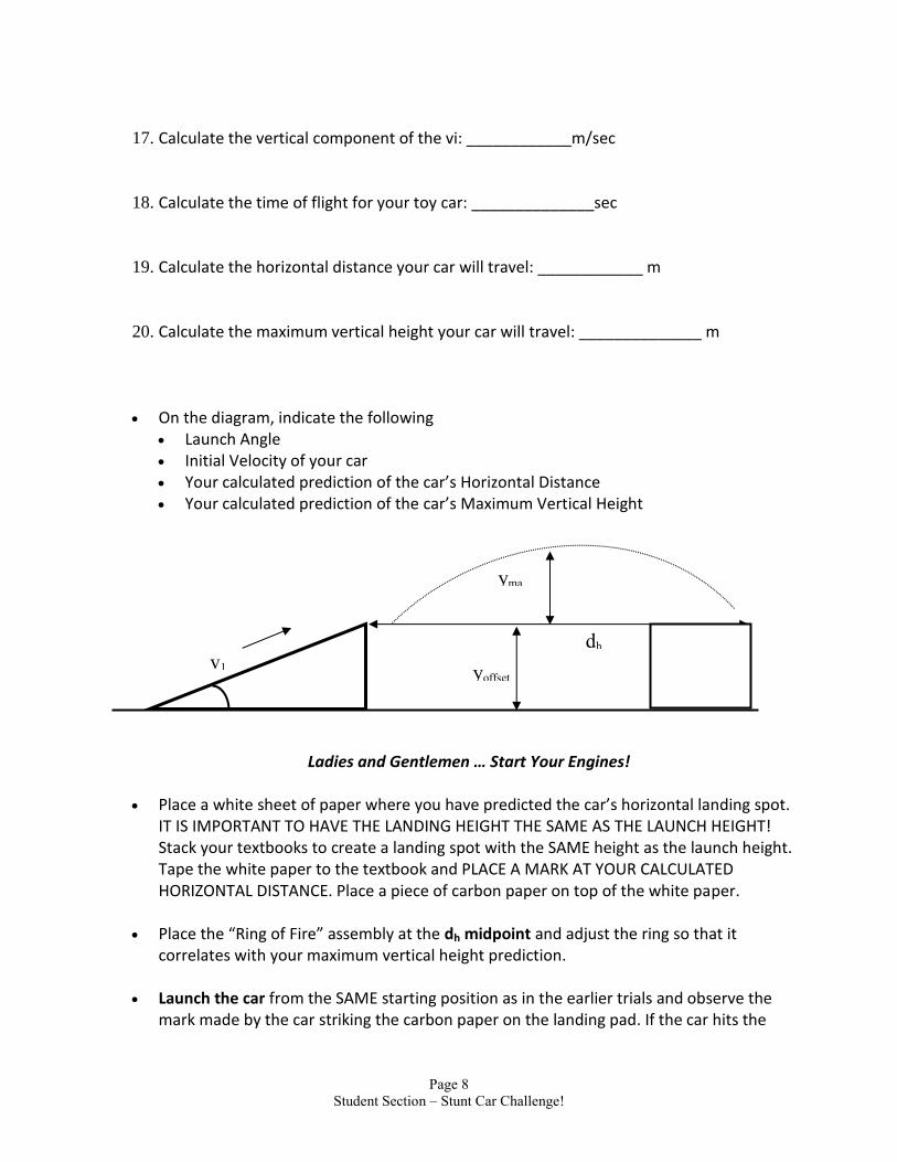
17. Calculate the vertical component of the vi: ____________m/sec 18. Calculate the time of flight for your toy car: ______________sec 19. Calculate the horizontal distance your car will travel: ____________ m 20. Calculate the maximum vertical height your car will travel: ______________ m On the diagram, indicate the following
Launch Angle Initial Velocity of your car Your calculated prediction of the car’s Horizontal Distance Your calculated prediction of the car’s Maximum Vertical Height
Ladies and Gentlemen … Start Your Engines! Place a white sheet of paper where you have predicted the car’s horizontal landing spot.
IT IS IMPORTANT TO HAVE THE LANDING HEIGHT THE SAME AS THE LAUNCH HEIGHT! Stack your textbooks to create a landing spot with the SAME height as the launch height. Tape the white paper to the textbook and PLACE A MARK AT YOUR CALCULATED HORIZONTAL DISTANCE. Place a piece of carbon paper on top of the white paper.
Place the “Ring of Fire” assembly at the dh midpoint and adjust the ring so that it
correlates with your maximum vertical height prediction. Launch the car from the SAME starting position as in the earlier trials and observe the
mark made by the car striking the carbon paper on the landing pad. If the car hits the
v1
yma
x
yoffset
dh

Page 9
Student Section – Stunt Car Challenge!
carbon paper, there should be a mark on the paper where your partner can measure the actual horizontal distance the car traveled. Record this distance below.
Calculated Horizontal Distance (meters) _____________________ Experimental Horizontal Distance (meters) ___________________
22. Calculate the Percent Difference between the calculated horizontal distance (Calc) and your experimental horizontal distance (Exp) using the equation below: 23. How well did your calculated results compare with the actual launch results? 24. If there was significant error, discuss some of the factors attributing to the fluctuations in the values? Part II Additional Questions: 25. A cannon is fired at 100m/sec at an angle of 30 degrees. Find the:
a. time in the air_____________ b. maximum height of the cannonball_____________ c. how far the cannonball travels horizontally_____________
Exp – Calc x 100 = %Difference = ____________
Calc
30o
100 m/s

Page 10
Student Section – Stunt Car Challenge!
26. Using a six-iron (45o loft) and the same launch velocity as on Earth (70 m/s), how far
horizontally did Apollo 14 Astronaut Alan Shepard drive a golf ball on the Moon? _______ [Hint… to find the time of flight, use g = 1.6 m/s2 for the Moon.]
45o
70 m/s