Embed Size (px)
Citation preview
Operation and Service Manual
Laser Guided Wheel Alignment SystemLaser Guided Wheel Alignment SystemLaser Guided Wheel Alignment SystemLaser Guided Wheel Alignment System
TL-12
Passenger Car Alignment
System
8231 Blaine Road
Blaine, WA 98230
360-371-0552
360-371-0553 fax
800-496-3777 toll free www.Tru-Line.net
2
TABLE OF CONTENTS
INTRODUCTION .......................................................................................................................................................3
HOW IT WORKS .......................................................................................................................................................4
READING THE SCALES: ..............................................................................................................................................4
GENERAL ALIGNMENT PROCEDURE ...............................................................................................................5
CALIBRATION PROCEDURES ..............................................................................................................................8
MOUNTING TL-28 WHEEL CLAMPS.................................................................................................................14
MOUNTING THE WHEEL CLAMPS: ...........................................................................................................................14
RUN OUT PROCEDURE.........................................................................................................................................15
RUN OUT PROCEDURE:............................................................................................................................................15
ACCOMIDATING OVERSIZED TRUCK TIRES ...............................................................................................17
MEASURING CAMBER:.............................................................................................................................................18
MEASURING CASTER: ..............................................................................................................................................18
MEASURING SAI: ....................................................................................................................................................19
LIVE CASTER ADJUSTMENT..............................................................................................................................20
TWO-WHEEL CENTERLINE ALIGNMENT......................................................................................................21
THRUST ANGLE ALIGNMENT............................................................................................................................24
THRUST ANGLE ALIGNMENT PROCEDURE:..............................................................................................................24
FOUR-WHEEL ALIGNMENT ...............................................................................................................................26
FOUR-WHEEL ALIGNMENT:.....................................................................................................................................27
MAINTENANCE, WARRANTY & SERVICE......................................................................................................29
MAINTENANCE: .......................................................................................................................................................29
TWO YEAR LIMITED WARRANTY: ...........................................................................................................................29
SERVICE INSTRUCTIONS...........................................................................................................................................30
3
INTRODUCTION
The Tru-Line TL-12 Laser Wheel Alignment System consists of the following components:
4- TL-28 Wheel Clamps 1- TL-37 Left Laser Gun
1- TL-30 Easy Check Gauge 1- TL-38 Right Combi Gauge
1- TL-31 Brake Pedal Depressor 1- TL-39 Left Combi Gauge
1- TL-32 Steering Wheel Holder 1- TL-40 Calibration Bar
1- TL-36 Right Laser Gun 1- Documentation
Optional components:
TLT-44 Level Compensator TL-500 Roll Around Cart
TR-15 Spacer Kit for Clamp
Note: Drawings of each component are included in the procedure sections to follow.
Passenger cars, RV`s, Trucks, and Race Cars can easily be aligned anywhere. No dedicated Rack
or level surface is required. The industry standard, Two-Wheel Centerline, Two-Wheel Thrust
Line, and Four Wheel Alignments can be easily accomplished by using the components above.
All of the gauges store on the Calibration Bar, so that a complete calibration of the system can be
easily done before use. The components can also be hung on a wall. Since a complete calibration
only takes a second, it is recommended that the system be calibrated before each use and
recalibrated when needed.
Tru-Line is pleased to have you and your company as a client. We are available to answer any
questions that you may have. Please feel free to contact us if there is anything further we can do
to make Tru-Line a better product for you and your company.
Tru-Line8231 Blaine Road
Blaine, WA 98230
360-371-0552
360-371-0553 fax
800-496-3777 toll free
www.Tru-Line.net
4
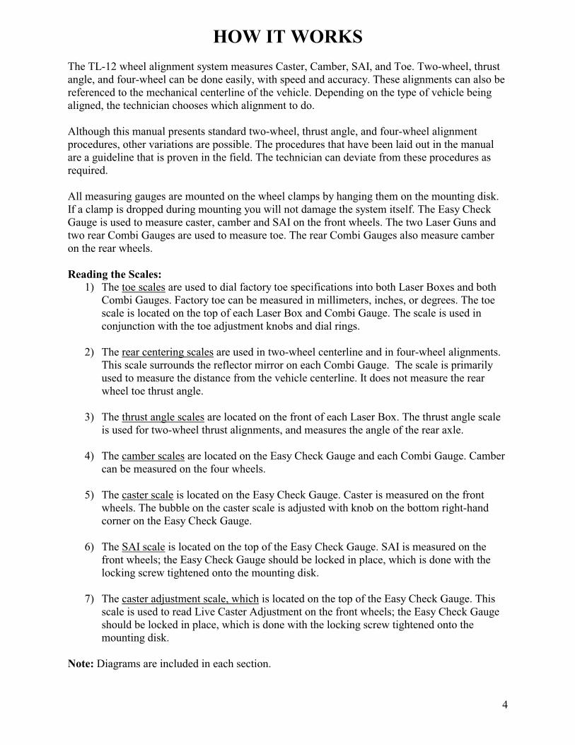
HOW IT WORKS
The TL-12 wheel alignment system measures Caster, Camber, SAI, and Toe. Two-wheel, thrust
angle, and four-wheel can be done easily, with speed and accuracy. These alignments can also be
referenced to the mechanical centerline of the vehicle. Depending on the type of vehicle being
aligned, the technician chooses which alignment to do.
Although this manual presents standard two-wheel, thrust angle, and four-wheel alignment
procedures, other variations are possible. The procedures that have been laid out in the manual
are a guideline that is proven in the field. The technician can deviate from these procedures as
required.
All measuring gauges are mounted on the wheel clamps by hanging them on the mounting disk.
If a clamp is dropped during mounting you will not damage the system itself. The Easy Check
Gauge is used to measure caster, camber and SAI on the front wheels. The two Laser Guns and
two rear Combi Gauges are used to measure toe. The rear Combi Gauges also measure camber
on the rear wheels.
Reading the Scales:
1) The toe scales are used to dial factory toe specifications into both Laser Boxes and both
Combi Gauges. Factory toe can be measured in millimeters, inches, or degrees. The toe
scale is located on the top of each Laser Box and Combi Gauge. The scale is used in
conjunction with the toe adjustment knobs and dial rings.
2) The rear centering scales are used in two-wheel centerline and in four-wheel alignments.
This scale surrounds the reflector mirror on each Combi Gauge. The scale is primarily
used to measure the distance from the vehicle centerline. It does not measure the rear
wheel toe thrust angle.
3) The thrust angle scales are located on the front of each Laser Box. The thrust angle scale
is used for two-wheel thrust alignments, and measures the angle of the rear axle.
4) The camber scales are located on the Easy Check Gauge and each Combi Gauge. Camber
can be measured on the four wheels.
5) The caster scale is located on the Easy Check Gauge. Caster is measured on the front
wheels. The bubble on the caster scale is adjusted with knob on the bottom right-hand
corner on the Easy Check Gauge.
6) The SAI scale is located on the top of the Easy Check Gauge. SAI is measured on the
front wheels; the Easy Check Gauge should be locked in place, which is done with the
locking screw tightened onto the mounting disk.
7) The caster adjustment scale, which is located on the top of the Easy Check Gauge. This
scale is used to read Live Caster Adjustment on the front wheels; the Easy Check Gauge
should be locked in place, which is done with the locking screw tightened onto the
mounting disk.
Note: Diagrams are included in each section.
5
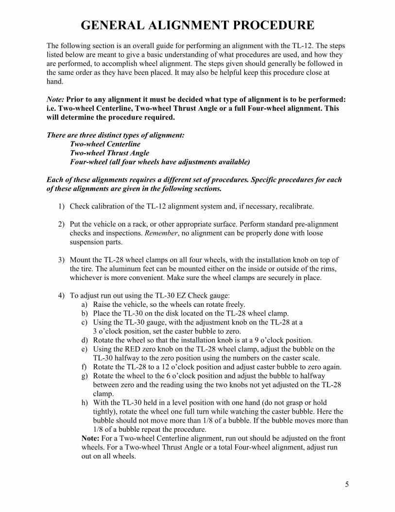
GENERAL ALIGNMENT PROCEDURE
The following section is an overall guide for performing an alignment with the TL-12. The steps
listed below are meant to give a basic understanding of what procedures are used, and how they
are performed, to accomplish wheel alignment. The steps given should generally be followed in
the same order as they have been placed. It may also be helpful keep this procedure close at
hand.
Note: Prior to any alignment it must be decided what type of alignment is to be performed:
i.e. Two-wheel Centerline, Two-wheel Thrust Angle or a full Four-wheel alignment. This
will determine the procedure required.
There are three distinct types of alignment:
Two-wheel Centerline
Two-wheel Thrust Angle
Four-wheel (all four wheels have adjustments available)
Each of these alignments requires a different set of procedures. Specific procedures for each
of these alignments are given in the following sections.
1) Check calibration of the TL-12 alignment system and, if necessary, recalibrate.
2) Put the vehicle on a rack, or other appropriate surface. Perform standard pre-alignment
checks and inspections. Remember, no alignment can be properly done with loose
suspension parts.
3) Mount the TL-28 wheel clamps on all four wheels, with the installation knob on top of
the tire. The aluminum feet can be mounted either on the inside or outside of the rims,
whichever is more convenient. Make sure the wheel clamps are securely in place.
4) To adjust run out using the TL-30 EZ Check gauge:
a) Raise the vehicle, so the wheels can rotate freely.
b) Place the TL-30 on the disk located on the TL-28 wheel clamp.
c) Using the TL-30 gauge, with the adjustment knob on the TL-28 at a
3 o’clock position, set the caster bubble to zero.
d) Rotate the wheel so that the installation knob is at a 9 o’clock position.
e) Using the RED zero knob on the TL-28 wheel clamp, adjust the bubble on the
TL-30 halfway to the zero position using the numbers on the caster scale.
f) Rotate the TL-28 to a 12 o’clock position and adjust caster bubble to zero again.
g) Rotate the wheel to the 6 o’clock position and adjust the bubble to halfway
between zero and the reading using the two knobs not yet adjusted on the TL-28
clamp.
h) With the TL-30 held in a level position with one hand (do not grasp or hold
tightly), rotate the wheel one full turn while watching the caster bubble. Here the
bubble should not move more than 1/8 of a bubble. If the bubble moves more than
1/8 of a bubble repeat the procedure.
Note: For a Two-wheel Centerline alignment, run out should be adjusted on the front
wheels. For a Two-wheel Thrust Angle or a total Four-wheel alignment, adjust run
out on all wheels.
6
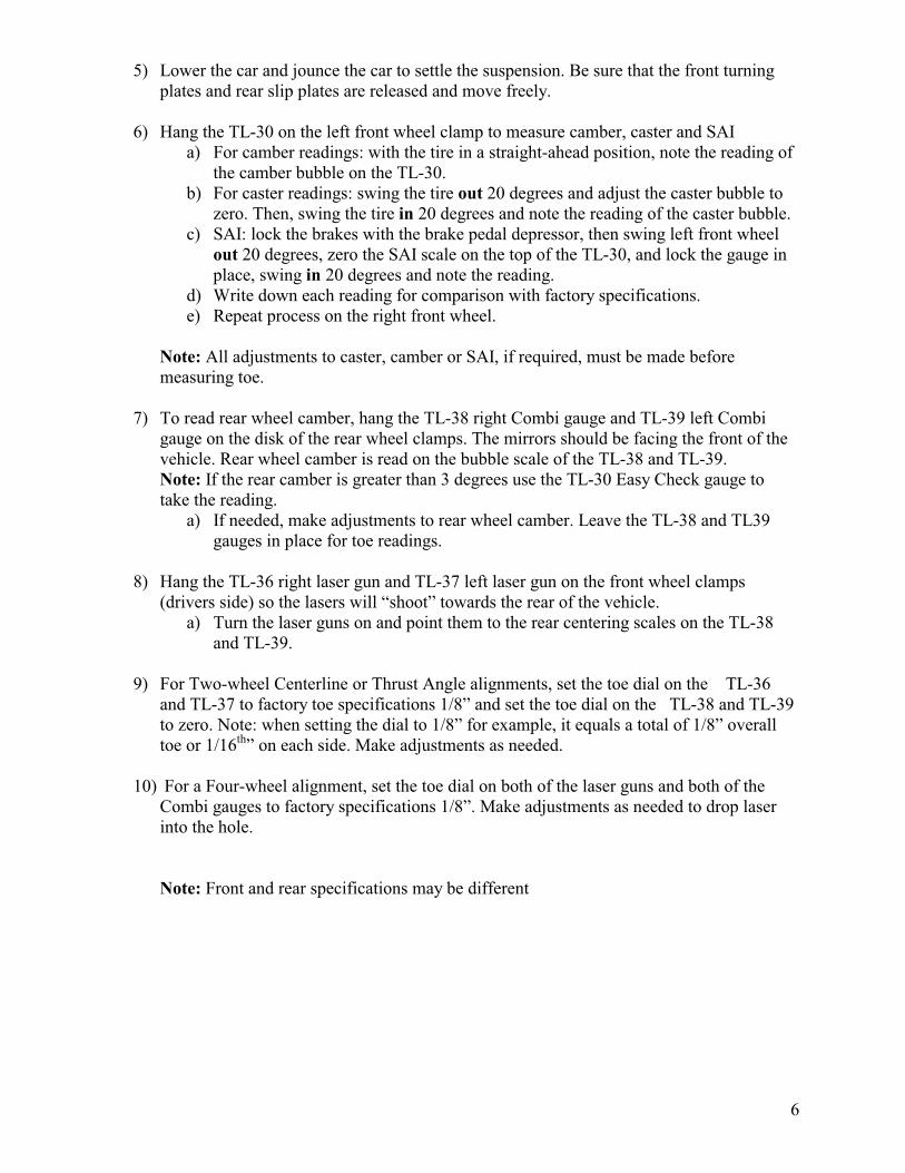
5) Lower the car and jounce the car to settle the suspension. Be sure that the front turning
plates and rear slip plates are released and move freely.
6) Hang the TL-30 on the left front wheel clamp to measure camber, caster and SAI
a) For camber readings: with the tire in a straight-ahead position, note the reading of
the camber bubble on the TL-30.
b) For caster readings: swing the tire out 20 degrees and adjust the caster bubble to
zero. Then, swing the tire in 20 degrees and note the reading of the caster bubble.
c) SAI: lock the brakes with the brake pedal depressor, then swing left front wheel
out 20 degrees, zero the SAI scale on the top of the TL-30, and lock the gauge in
place, swing in 20 degrees and note the reading.
d) Write down each reading for comparison with factory specifications.
e) Repeat process on the right front wheel.
Note: All adjustments to caster, camber or SAI, if required, must be made before
measuring toe.
7) To read rear wheel camber, hang the TL-38 right Combi gauge and TL-39 left Combi
gauge on the disk of the rear wheel clamps. The mirrors should be facing the front of the
vehicle. Rear wheel camber is read on the bubble scale of the TL-38 and TL-39.
Note: If the rear camber is greater than 3 degrees use the TL-30 Easy Check gauge to
take the reading.
a) If needed, make adjustments to rear wheel camber. Leave the TL-38 and TL39
gauges in place for toe readings.
8) Hang the TL-36 right laser gun and TL-37 left laser gun on the front wheel clamps
(drivers side) so the lasers will “shoot” towards the rear of the vehicle.
a) Turn the laser guns on and point them to the rear centering scales on the TL-38
and TL-39.
9) For Two-wheel Centerline or Thrust Angle alignments, set the toe dial on the TL-36
and TL-37 to factory toe specifications 1/8” and set the toe dial on the TL-38 and TL-39
to zero. Note: when setting the dial to 1/8” for example, it equals a total of 1/8” overall
toe or 1/16th
” on each side. Make adjustments as needed.
10) For a Four-wheel alignment, set the toe dial on both of the laser guns and both of the
Combi gauges to factory specifications 1/8”. Make adjustments as needed to drop laser
into the hole.
Note: Front and rear specifications may be different
7
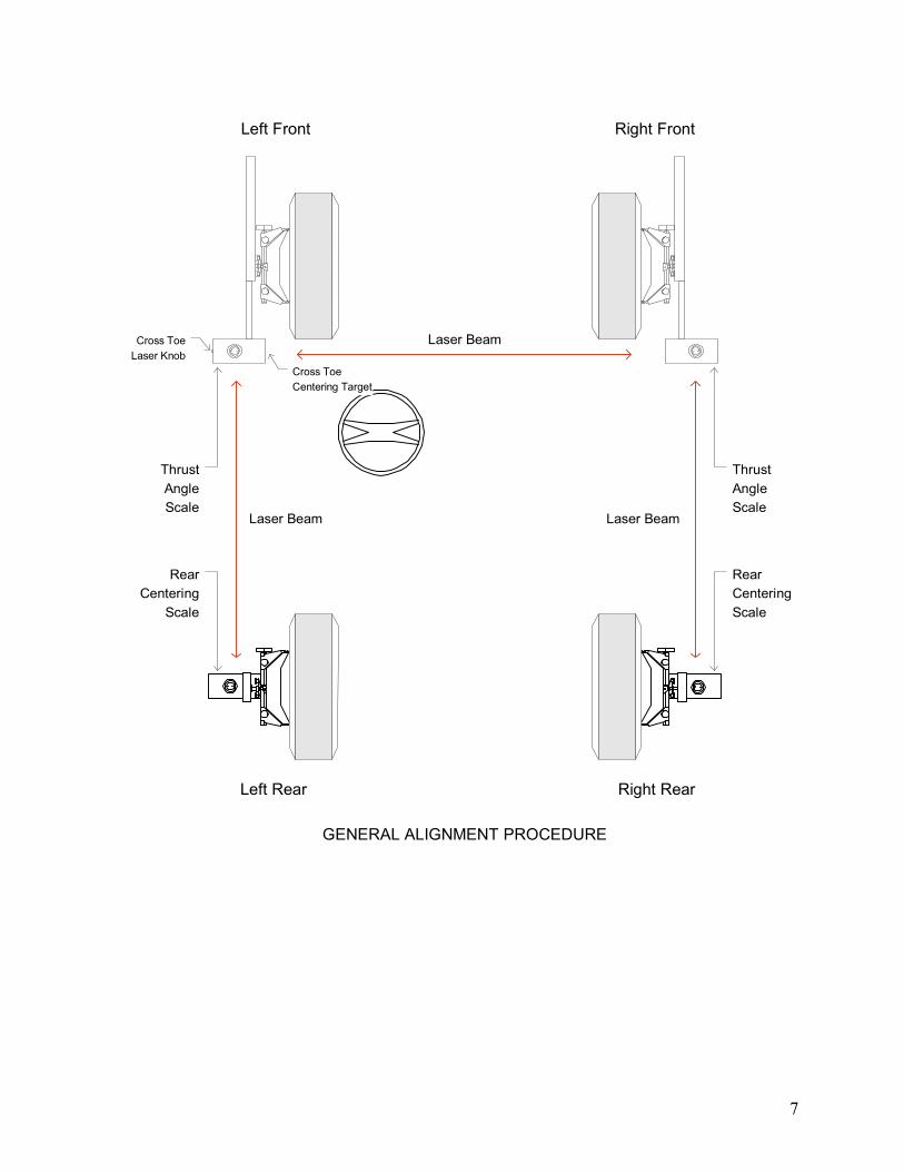
Left Front Right Front
Right RearLeft Rear
Laser Beam
Laser Beam Laser Beam
Cross Toe
Centering Target
Cross Toe
Laser Knob
GENERAL ALIGNMENT PROCEDURE
Rear
Centering
Scale
Rear
Centering
Scale
Thrust
Angle
Scale
Thrust
Angle
Scale
8
CALIBRATION PROCEDURES
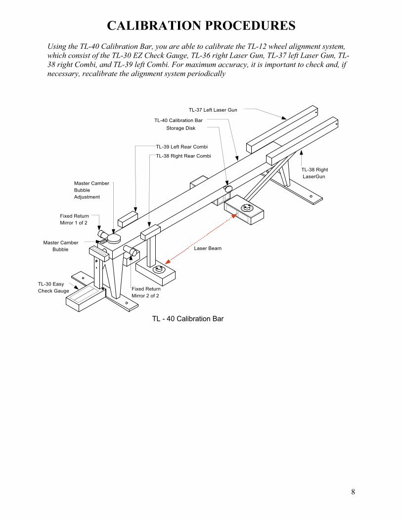
Using the TL-40 Calibration Bar, you are able to calibrate the TL-12 wheel alignment system,
which consist of the TL-30 EZ Check Gauge, TL-36 right Laser Gun, TL-37 left Laser Gun, TL-
38 right Combi, and TL-39 left Combi. For maximum accuracy, it is important to check and, if
necessary, recalibrate the alignment system periodically
TL-37 Left Laser Gun
TL-40 Calibration Bar
Storage Disk
TL-39 Left Rear Combi
TL-38 Right Rear Combi
Master Camber
Bubble
Master Camber
Bubble
Adjustment
Fixed Return
Mirror 1 of 2
Fixed Return
Mirror 2 of 2
TL-30 Easy
Check Gauge
TL-38 Right
LaserGun
Laser Beam
TL - 40 Calibration Bar
9
First: Calibrating the camber of the TL-30, TL-38, and TL-39.
Note: There is a pivot plate at the end of the TL-40, which has a mounting disc attached to the
end, a master bubble vial affixed to the plate, and an adjustment knob. The pivot plate is
designed to eliminate any pitch in the bar or non-level surface. It is used to calibrate the camber
vials on the TL-30 and both Combi gauges.
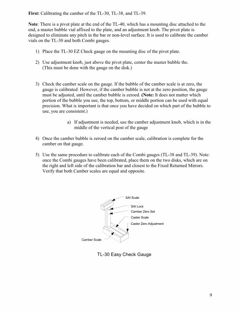
1) Place the TL-30 EZ Check gauge on the mounting disc of the pivot plate.
2) Use adjustment knob, just above the pivot plate, center the master bubble the.
(This must be done with the gauge on the disk.)
3) Check the camber scale on the gauge. If the bubble of the camber scale is at zero, the
gauge is calibrated. However, if the camber bubble is not at the zero position, the gauge
must be adjusted, until the camber bubble is zeroed. (Note: It does not matter which
portion of the bubble you use, the top, bottom, or middle portion can be used with equal
precision. What is important is that once you have decided on which part of the bubble to
use, you are consistent.)
a) If adjustment is needed, use the camber adjustment knob, which is in the
middle of the vertical post of the gauge
4) Once the camber bubble is zeroed on the camber scale, calibration is complete for the
camber on that gauge.
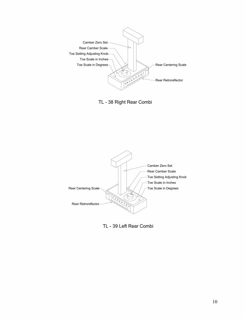
5) Use the same procedure to calibrate each of the Combi gauges (TL-38 and TL-39). Note:
once the Combi gauges have been calibrated, place them on the two disks, which are on
the right and left side of the calibration bar and closest to the Fixed Returned Mirrors.
Verify that both Camber scales are equal and opposite.
Caster Zero Adjustment
Caster Scale
Camber Scale
TL-30 Easy Check Gauge
SAI Scale
Camber Zero Set
SAI Lock
10
12
34
56
78
9
Camber Zero Set
Rear Camber Scale
Toe Setting Adjusting Knob
Toe Scale in Inches
Toe Scale in Degrees Rear Centering Scale
Rear Retroreflector
TL - 38 Right Rear Combi
Camber Zero Set
Rear Camber Scale
Toe Setting Adjusting Knob
Toe Scale in Inches
Toe Scale in DegreesRear Centering Scale
Rear Retroreflector
TL - 39 Left Rear Combi
98
76
54
32
1
11
Second: Calibrating the toe settings for TL-36 right Laser Gun and TL-37 left Laser Gun.
1) Place the TL-36 and TL-37 on the set of disks furthest from the Fixed Return Mirrors, so
the lasers are pointing towards them. Place the Laser Guns on the disks at the slot
location located on the bottom of the Laser Guns, push down until you here a click.
2) Turn the lasers on, using the white button. There is a red light next to the button that will
illuminate when there is power to the Laser Gun. There should also be a laser shinning
out the front of each of the laser boxes.
3) Check to make sure the toe dial is set to zero: i.e., the red ring around the toe knob on the
top of each laser box is zeroed on the scale. If not, turn the toe knob until each dial is set
to zero.
4) Point the lasers directly at the Fixed Return Mirrors. The lasers should reflect back onto
the scales in the front of the laser boxes (or Thrust Angle scales).
5) Check the laser on the Thrust Angle scale on the front of each Laser Gun. If the laser
reflects back to the hole on the scales, then the Laser Gun is calibrated; no further
adjustment is needed. If either of the lasers does not reflect back into the hole, then
follow these steps:
Note: When referring to the “hole” we are referring the hole located on the laser gun scales
(thrust angle scales) at the number 5 has a hole where the laser comes out.
a) Adjust the toe knob of the laser box until the laser beam reflects back in the hole
on the Thrust Angle scale.
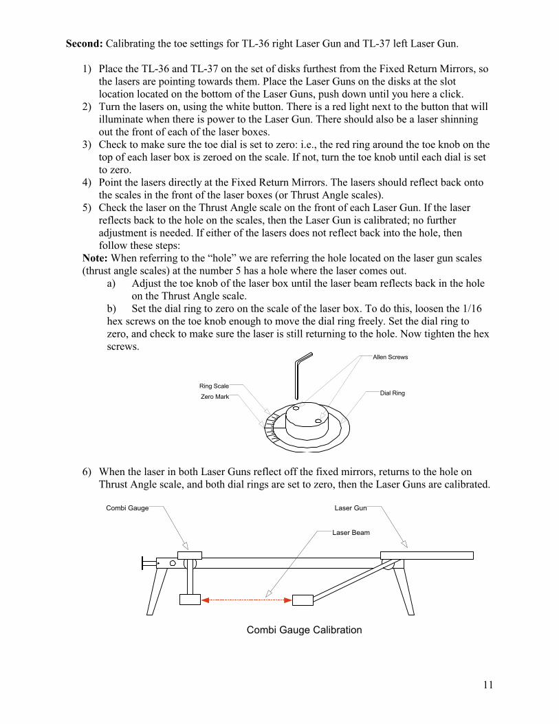
b) Set the dial ring to zero on the scale of the laser box. To do this, loosen the 1/16
hex screws on the toe knob enough to move the dial ring freely. Set the dial ring to
zero, and check to make sure the laser is still returning to the hole. Now tighten the hex
screws.
Dial Ring
Allen Screws
Ring Scale
Zero Mark
6) When the laser in both Laser Guns reflect off the fixed mirrors, returns to the hole on
Thrust Angle scale, and both dial rings are set to zero, then the Laser Guns are calibrated.
Combi Gauge Laser Gun
Laser Beam
Combi Gauge Calibration
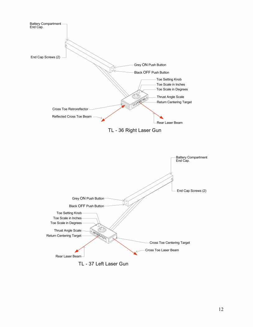
12
Battery CompartmentEnd Cap.
End Cap Screws (2)
Grey ON Push Button
Black OFF Push Button
Toe Setting Knob
Toe Scale in Inches
Toe Scale in Degrees
Return Centering Target
Thrust Angle Scale
1234789
65
Rear Laser Beam
Cross Toe Retroreflector
Reflected Cross Toe Beam
TL - 36 Right Laser Gun
Battery CompartmentEnd Cap.
End Cap Screws (2)
Grey ON Push Button
Black OFF Push Button
Toe Setting Knob
Toe Scale in Inches
Toe Scale in Degrees
Return Centering Target
Thrust Angle Scale
123478965
Rear Laser Beam
Cross Toe Centering Target
Cross Toe Laser Beam
TL - 37 Left Laser Gun
13
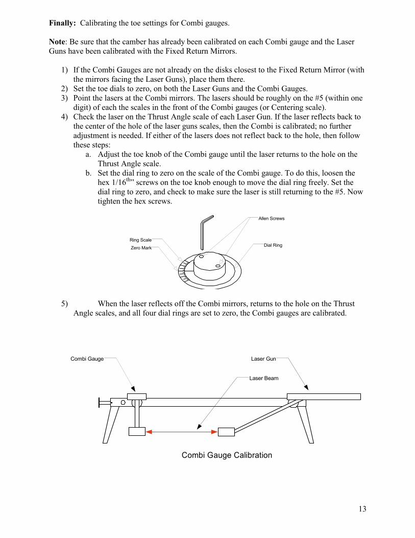
Finally: Calibrating the toe settings for Combi gauges.
Note: Be sure that the camber has already been calibrated on each Combi gauge and the Laser
Guns have been calibrated with the Fixed Return Mirrors.
1) If the Combi Gauges are not already on the disks closest to the Fixed Return Mirror (with
the mirrors facing the Laser Guns), place them there.
2) Set the toe dials to zero, on both the Laser Guns and the Combi Gauges.
3) Point the lasers at the Combi mirrors. The lasers should be roughly on the #5 (within one
digit) of each the scales in the front of the Combi gauges (or Centering scale).
4) Check the laser on the Thrust Angle scale of each Laser Gun. If the laser reflects back to
the center of the hole of the laser guns scales, then the Combi is calibrated; no further
adjustment is needed. If either of the lasers does not reflect back to the hole, then follow
these steps:
a. Adjust the toe knob of the Combi gauge until the laser returns to the hole on the
Thrust Angle scale.
b. Set the dial ring to zero on the scale of the Combi gauge. To do this, loosen the
hex 1/16th
” screws on the toe knob enough to move the dial ring freely. Set the
dial ring to zero, and check to make sure the laser is still returning to the #5. Now
tighten the hex screws.
Dial Ring
Allen Screws
Ring Scale
Zero Mark
5) When the laser reflects off the Combi mirrors, returns to the hole on the Thrust
Angle scales, and all four dial rings are set to zero, the Combi gauges are calibrated.
Combi Gauge Laser Gun
Laser Beam
Combi Gauge Calibration
14
MOUNTING TL-28 WHEEL CLAMPS
The wheel clamps can be attached to either the inside or the outside of the rim (whichever is
easiest). They can be mounted on a wheel rim 10 inches to 19 inches in diameter, and the
aluminum feet are less likely to damage polished aluminum rims.
Mounting the Wheel Clamps:
1) Adjust the installation knob either in or out until the feet will fit the wheel rim.
2) Rotate the mounting feet until they are all facing either the inside or outside of the rim.
(This depends upon which side of the rim the wheel clamps are mounted.)
3) Place the mounting feet onto the rim. Make sure they are all attached to the rim.
4) Use the installation knob to tighten the feet to the rim.
5) Make sure the mounting feet are securely on the rim. If they are not securely attached, tap
each leg with the palm of your hand and tighten the feet a little more with the installation
knob.(Repeat this process, until the mounting feet are secure.)
6) Perform the runout procedure on the appropriate wheel clamps.
Note: Although the slide plate assembly is usually centered, for a large diameter wheel, you can
loosen the locking screws and move the slide plate to the edge of wheel clamp; then, tighten the
locking screws. This will assure that the laser will shoot across the rear of the tires. Do this
before performing run out.
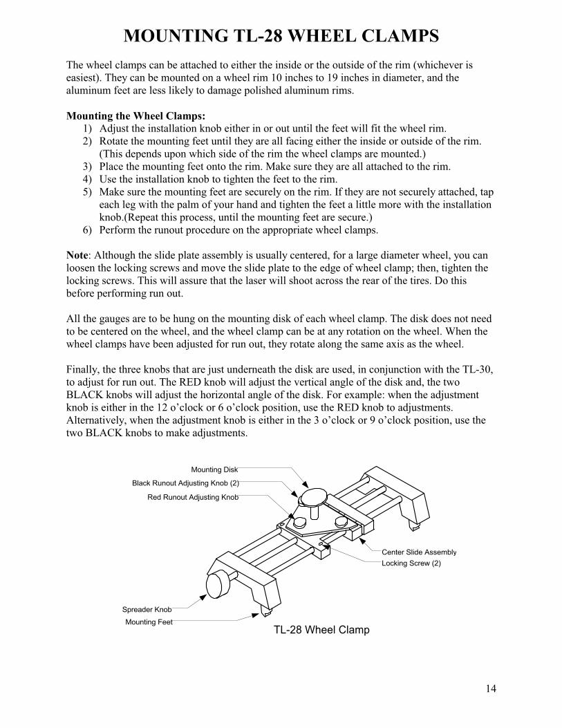
All the gauges are to be hung on the mounting disk of each wheel clamp. The disk does not need
to be centered on the wheel, and the wheel clamp can be at any rotation on the wheel. When the
wheel clamps have been adjusted for run out, they rotate along the same axis as the wheel.
Finally, the three knobs that are just underneath the disk are used, in conjunction with the TL-30,
to adjust for run out. The RED knob will adjust the vertical angle of the disk and, the two
BLACK knobs will adjust the horizontal angle of the disk. For example: when the adjustment
knob is either in the 12 o’clock or 6 o’clock position, use the RED knob to adjustments.
Alternatively, when the adjustment knob is either in the 3 o’clock or 9 o’clock position, use the
two BLACK knobs to make adjustments.
Mounting Disk
Black Runout Adjusting Knob (2)
Center Slide Assembly
Locking Screw (2)
Spreader Knob
Mounting Feet
Red Runout Adjusting Knob
TL-28 Wheel Clamp
15
RUN OUT PROCEDURE
Once the wheel clamps have been mounted, run out should either be performed on the two front
wheels or all four, depending what type alignment is preferred. For a Two-wheel Centerline
alignment, adjust run out on both front wheels. For a Thrust Angle alignment, or Four-wheel
total alignment, adjust run out on all four wheels.
The following should be completed before run out adjustments are made:
• Front and rear wheel clamps must be installed
• The vehicle must be raised, so the wheels can rotate freely.
Run Out Procedure:
1) Place the TL-30 on the disc extending from the wheel clamp.
2) Level the TL-30, using the SAI scale on the top of the post. Make sure the TL-30 can
move easily, so that it stays relatively level when the wheel clamp is rotated.
3) Rotate the wheel clamp until the installation knob is at a 12 o’clock position. Set the
caster bubble to zero on the caster scale; this is done with the caster adjustment knob,
which is located on body of the TL-30.
4) Rotate the wheel clamp ½ turn; the installation knob should be at a 6 o’clock position.
5) Level the TL-30 and read the number on the caster scale.
6) Adjust the bubble to the point halfway between 0 and the current reading using the RED
knob on the TL-28. (When making this adjustment, it is important not to move the bubble
with the caster adjustment knob.)
7) Rotate the wheel ¼ turn to the right, so the installation knob is at a 9 o’clock position.
8) Level the TL-30, and set the caster bubble to zero with caster adjustment knob.
9) Rotate the wheel ½ turn, until the installation knob is at a 3 o’clock position.
10) Level the TL-30, read the number on the caster scale.
11) Adjust the caster bubble to the point halfway between 0 and the current reading, using the
two BLACK knobs on the wheel clamp.
12) Rotate the wheel until the installation knob is at a 12 o’clock position. Level the
TL-30, and adjust the caster knob until the caster bubble reads zero.
13) With the TL-30 held in a level position with one hand (do not grasp or hold tightly),
rotate the wheel one full turn while watching the caster bubble. The bubble should not
move more than 1/8 of a bubble. If the bubble does move repeat the run out procedure.
16
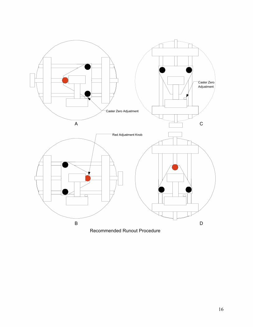
Recommended Runout Procedure
A
B
C
D
Caster Zero Adjustment
Caster Zero
Adjustment
Red Adjustment Knob
17
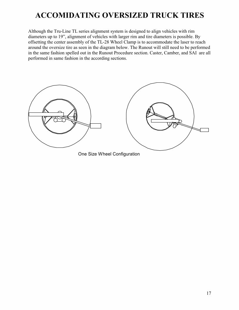
ACCOMIDATING OVERSIZED TRUCK TIRES
Although the Tru-Line TL series alignment system is designed to align vehicles with rim
diameters up to 19”, alignment of vehicles with larger rim and tire diameters is possible. By
offsetting the center assembly of the TL-28 Wheel Clamp is to accommodate the laser to reach
around the oversize tire as seen in the diagram below. The Runout will still need to be performed
in the same fashion spelled out in the Runout Procedure section. Caster, Camber, and SAI are all
performed in same fashion in the according sections.
One Size Wheel Configuration
18
MEASURING CAMBER, CASTER, AND SAI
Measuring Caster, Camber or SAI is very simple and fast.
Before performing these measurements:
• The equipment must be calibrated.
• The wheel clamps must be mounted and adjusted for run out.
• The full weight of the vehicle must be on its wheels
• It is recommended to use turntables and slip plates when measuring caster, camber and
SAI.
• The vehicle should be jounced to settle the suspension
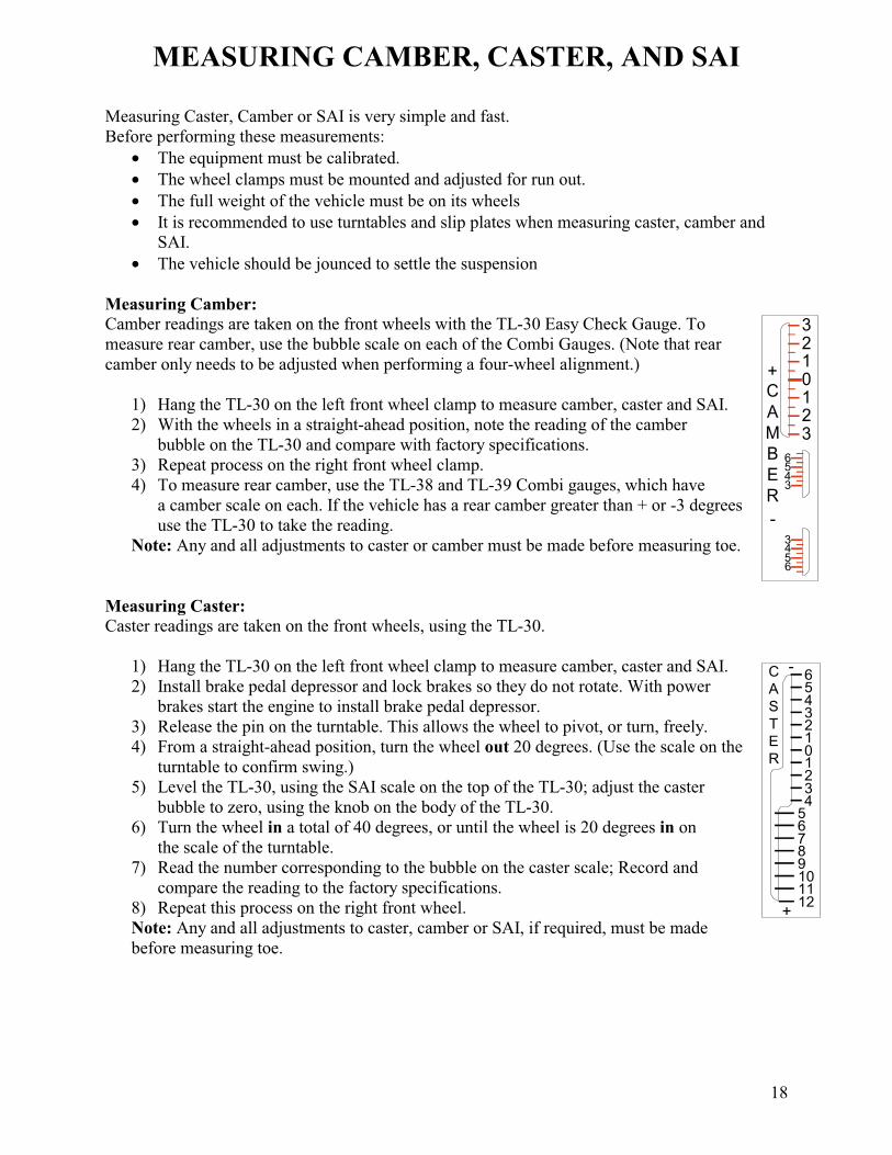
Measuring Camber:
Camber readings are taken on the front wheels with the TL-30 Easy Check Gauge. To
measure rear camber, use the bubble scale on each of the Combi Gauges. (Note that rear
camber only needs to be adjusted when performing a four-wheel alignment.)
1) Hang the TL-30 on the left front wheel clamp to measure camber, caster and SAI.
2) With the wheels in a straight-ahead position, note the reading of the camber
bubble on the TL-30 and compare with factory specifications.
3) Repeat process on the right front wheel clamp.
4) To measure rear camber, use the TL-38 and TL-39 Combi gauges, which have
a camber scale on each. If the vehicle has a rear camber greater than + or -3 degrees
use the TL-30 to take the reading.
Note: Any and all adjustments to caster or camber must be made before measuring toe.
Measuring Caster:
Caster readings are taken on the front wheels, using the TL-30.
1) Hang the TL-30 on the left front wheel clamp to measure camber, caster and SAI.
2) Install brake pedal depressor and lock brakes so they do not rotate. With power
brakes start the engine to install brake pedal depressor.
3) Release the pin on the turntable. This allows the wheel to pivot, or turn, freely.
4) From a straight-ahead position, turn the wheel out 20 degrees. (Use the scale on the
turntable to confirm swing.)
5) Level the TL-30, using the SAI scale on the top of the TL-30; adjust the caster
bubble to zero, using the knob on the body of the TL-30.
6) Turn the wheel in a total of 40 degrees, or until the wheel is 20 degrees in on
the scale of the turntable.
7) Read the number corresponding to the bubble on the caster scale; Record and
compare the reading to the factory specifications.
8) Repeat this process on the right front wheel.
Note: Any and all adjustments to caster, camber or SAI, if required, must be made
before measuring toe.
0123456
1234
56789101112
+
-C
A
S
T
E
R
0123
123
6543
6543
+
-
C
A
M
B
E
R
19
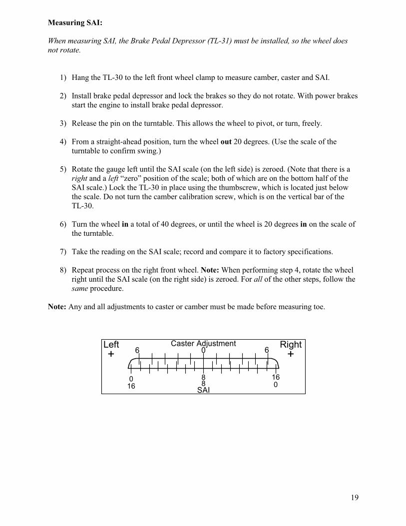
Measuring SAI:
When measuring SAI, the Brake Pedal Depressor (TL-31) must be installed, so the wheel does
not rotate.
1) Hang the TL-30 to the left front wheel clamp to measure camber, caster and SAI.
2) Install brake pedal depressor and lock the brakes so they do not rotate. With power brakes
start the engine to install brake pedal depressor.
3) Release the pin on the turntable. This allows the wheel to pivot, or turn, freely.
4) From a straight-ahead position, turn the wheel out 20 degrees. (Use the scale of the
turntable to confirm swing.)
5) Rotate the gauge left until the SAI scale (on the left side) is zeroed. (Note that there is a
right and a left “zero” position of the scale; both of which are on the bottom half of the
SAI scale.) Lock the TL-30 in place using the thumbscrew, which is located just below
the scale. Do not turn the camber calibration screw, which is on the vertical bar of the
TL-30.
6) Turn the wheel in a total of 40 degrees, or until the wheel is 20 degrees in on the scale of
the turntable.
7) Take the reading on the SAI scale; record and compare it to factory specifications.
8) Repeat process on the right front wheel. Note: When performing step 4, rotate the wheel
right until the SAI scale (on the right side) is zeroed. For all of the other steps, follow the
same procedure.
Note: Any and all adjustments to caster or camber must be made before measuring toe.
Caster AdjustmentLeft Right
SAI
6 0
8 16
+ +6
0016 8
20
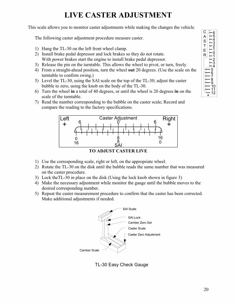
LIVE CASTER ADJUSTMENT
This scale allows you to monitor caster adjustments while making the changes the vehicle.
The following caster adjustment procedure measure caster.
1) Hang the TL-30 on the left front wheel clamp.
2) Install brake pedal depressor and lock brakes so they do not rotate.
With power brakes start the engine to install brake pedal depressor.
3) Release the pin on the turntable. This allows the wheel to pivot, or turn, freely.
4) From a straight-ahead position, turn the wheel out 20 degrees. (Use the scale on the
turntable to confirm swing.)
5) Level the TL-30, using the SAI scale on the top of the TL-30; adjust the caster
bubble to zero, using the knob on the body of the TL-30.
6) Turn the wheel in a total of 40 degrees, or until the wheel is 20 degrees in on the
scale of the turntable.
7) Read the number corresponding to the bubble on the caster scale; Record and
compare the reading to the factory specifications.
Caster AdjustmentLeft Right
SAI
6 0
8 16
+ +6
0016 8
TO ADJUST CASTER LIVE
1) Use the corresponding scale, right or left, on the appropriate wheel.
2) Rotate the TL-30 on the disk until the bubble reads the same number that was measured
on the caster procedure.
3) Lock theTL-30 in place on the disk (Using the lock knob shown in figure 3)
4) Make the necessary adjustment while monitor the gauge until the bubble moves to the
desired corresponding number.
5) Repeat the caster measurement procedure to confirm that the caster has been corrected.
Make additional adjustments if needed.
Caster Zero Adjustment
Caster Scale
Camber Scale
TL-30 Easy Check Gauge
SAI Scale
Camber Zero Set
SAI Lock
0123456
1234
56789101112
+
-C
A
S
T
E
R
21
TWO-WHEEL CENTERLINE ALIGNMENT
The purpose of a Two-wheel Centerline alignment is to align the front wheels to the theoretical
centerline of the vehicle. This is accomplished by adjusting the front wheels to match up with the
centerline of the vehicle. Note: the Two-wheel Centerline procedure is the first step of the Thrust
Angle and Four-wheel alignments.
The following should be completed before making any measurements or adjustments:
1) Equipment should be checked for calibration
2) The full weight of the vehicle must be on its wheels
3) The suspension must be inspected
4) Front and rear wheel clamps must be installed
5) Runout must be completed on the front wheel clamps
6) Adjustments for caster, camber, and SAI should have already been completed
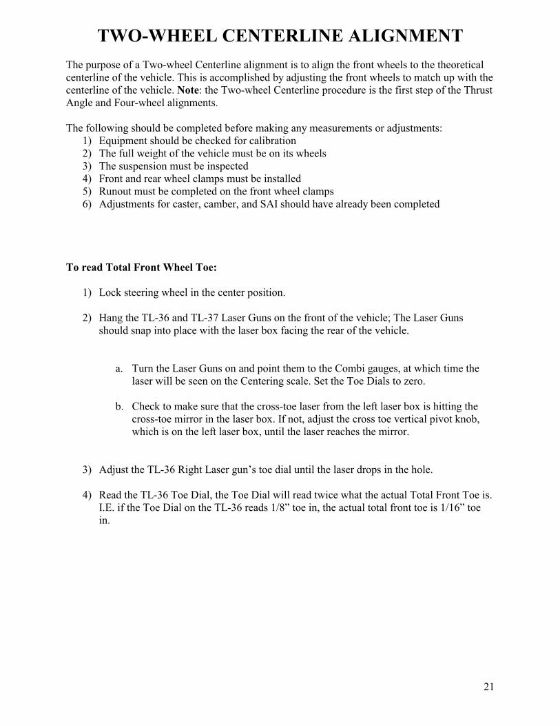
To read Total Front Wheel Toe:
1) Lock steering wheel in the center position.
2) Hang the TL-36 and TL-37 Laser Guns on the front of the vehicle; The Laser Guns
should snap into place with the laser box facing the rear of the vehicle.
a. Turn the Laser Guns on and point them to the Combi gauges, at which time the
laser will be seen on the Centering scale. Set the Toe Dials to zero.
b. Check to make sure that the cross-toe laser from the left laser box is hitting the
cross-toe mirror in the laser box. If not, adjust the cross toe vertical pivot knob,
which is on the left laser box, until the laser reaches the mirror.
3) Adjust the TL-36 Right Laser gun’s toe dial until the laser drops in the hole.
4) Read the TL-36 Toe Dial, the Toe Dial will read twice what the actual Total Front Toe is.
I.E. if the Toe Dial on the TL-36 reads 1/8” toe in, the actual total front toe is 1/16” toe
in.
22
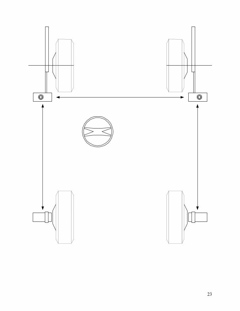
Two-wheel centerline alignment procedure:
1) Lock steering wheel in the center position
2) Hang TL-38 and TL-39 Combi gauges on the rear wheels, with the Centering scale facing
towards the front of the vehicle. Set the toe dials to zero.
3) Hang the TL-36 and TL-37 Laser Guns on the front of the vehicle; The Laser Guns
should snap into place with the laser box facing the rear of the vehicle.
a. Turn the Laser Guns on and point them to the Combi gauges, at which time the
laser will be seen on the Centering scale.
b. Check to make sure that the cross-toe laser from the left laser box is hitting the
cross-toe mirror in the laser box. If not, adjust the cross toe vertical pivot knob, which
is on the left laser box, until the laser reaches the mirror.
4) Set the toe dial on the TL-36 and TL-37 to factory toe specifications 1/8”.
Note: when setting the dial, for example, to 1/8, it equals a total of 1/8 overall toe or
a 1/16th
on each side. Leave the toe dial at zero on the Combi gauges.
5) Adjust the front tie rods until the cross-toe laser is reflected from the cross-toe mirror
back into the hole. At this point, the lasers should also be hitting the Centering scales,
which are on the front of the Combi gauges. Check the numbers that the lasers are hitting.
a. Your objective is to “match the numbers,” or hit the same number on each
Centering scale, with a tolerance of ½ a digit. For example, if you are hitting a 4
½ on the left scale and a 5 on the right scale, this is acceptable.
b. If you are hitting a 2 on the right scale and 6 on the left scale, then further
adjustment is required. In this case, add the numbers together (2+6=8) and then
divide the total in half (8/2=4) to get your target number (4).
c. In this example, 4 is your target number, adjust the front tie rods until the lasers
hit the 4 on the scales, thus “matching the numbers.”
Note: After making adjustments to the tie rods, it is important that the cross-toe laser
still be in the hole.
The Two-wheel Centerline alignment is complete when the cross-toe laser is reflected off the
cross-toe mirror back into the hole and the numbers on the Centering scales match.
23
24
THRUST ANGLE ALIGNMENT
The purpose of a Thrust Angle alignment is to adjust the front wheels until they are aligned with
the rear axle. This alignment is typically done to vehicles that have no rear wheel adjustment
available. This type of alignment gives the customer a straight steering wheel and minimizes tire
wear on the front only, and allows you to measure which direction the rear of the vehicle is
inclined to travel, or the thrust angle of the vehicle.
The following should be completed before making any measurements or adjustments:
1) Equipment should be checked for calibration
2) The full weight of the vehicle must be on its wheels
3) The suspension must be inspected
4) Front and rear wheel clamps must be installed
5) Runout must be completed on all wheel clamps
6) Adjustments for caster, camber, and SAI should have already been completed
Thrust Angle Alignment Procedure:
NOTE: Using the procedure of the TWO WHEEL CENTERLINE ALIGNMENT sections
complete the additional procedures to complete a THRUST ANGLE ALIGNMENT.
6) Adjust the front tie rods until the cross-toe laser is reflected back into the hole: i.e., the
laser from the left laser box, is reflected off the toe mirror in the right laser box and back
into the hole of the left laser box.
7) Look at the Thrust Angle scales (on the front of the laser boxes). Adjust each of the front
tie rods evenly until the lasers hit the same numbers on the Thrust Angle scales. As
described in the Centerline Alignment procedure step #5. Making sure that you are
reading the Thrust Angle scales and not the Centering scales.
Note: each tie rod must be adjusted evenly, in relation to the other. Make sure the cross-toe
laser is still in the hole.
The Thrust Angle alignment is complete when the cross-toe laser is reflected off the cross-toe
mirror and back into the hole, as well as the two other lasers are reflecting off the Centering
scales and hit same numbers on the Thrust Angle scales.
Reference Note: At this point, if the customer does not have a straight steering wheel, perform a
Two-wheel Centerline alignment, and then repeat the process above.
25
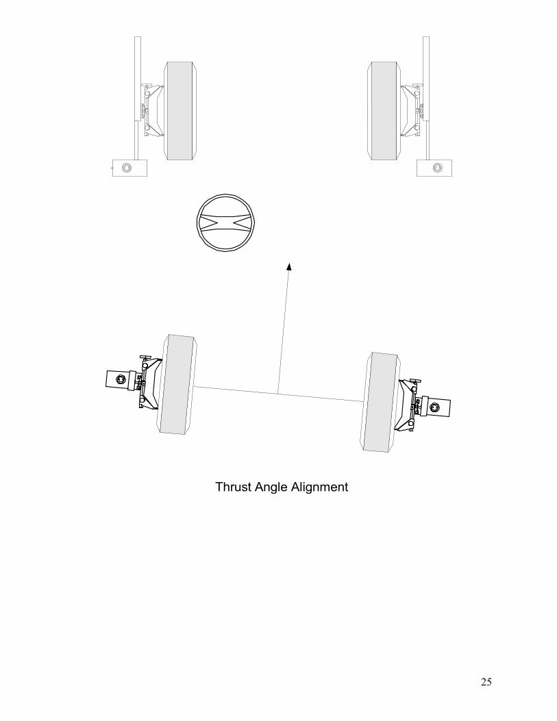
Thrust Angle Alignment
26
FOUR-WHEEL ALIGNMENT
The objective in a Four-wheel alignment is to adjust all four wheels until they are aligned to the
factory specification. This alignment is typically done to vehicles that have rear wheel
adjustment available.
The following should be completed before making any measurements or adjustments:
1) Equipment should be checked for calibration.
2) The full weight of the vehicle must be on its wheels turntables in the front and slip plates
in the rear.
3) The suspension must be inspected
4) Front and rear wheel clamps must be installed
5) Run out must be completed on all wheel clamps
6) Adjustments for caster and camber should have already been completed
To read total four wheel toe:
1) Complete the procedure as described in the Centerline Alignment portion of this manual
to read the total front wheel toe and then complete the following steps.
2) Hang the TL-36, 37, 38, & 39 gauges on their respective disks and zero the toe dials on
all of the gauges. Turn on the lasers.
3) Adjust the TL-37 Left Laser Gun toe dial until the Laser beam drops back into the hole
on the Thrust Angle Scale.
4) Adjust the TL-36 Right Laser Gun toe dial until the Cross-Toe Laser drops back into the
hole.
5) Adjust the TL-38 Right Rear Combi Gauge toe dial until the laser beam moves back one
half of the distance to the hole on the Thrust Angle Scale. I.E. if the laser beam hits the
3on the Thrust Angle Scale. You would move the toe dial until the laser beam hits the 4
on the Thrust Angle Scale.
6) Read the Total Rear Toe. I. E. if the toe dial on the TL-38 reads 1/8” out; the actual Total
Rear Toe is 1/16” out.
27
Four-Wheel Alignment:
1) Lock steering wheel in the center position, or until the front wheels are in the straight-
ahead position.
2) Hang TL-38 and TL-39 Combi gauges on the rear wheels with the Centering scale facing
toward the front of the vehicle. Set toe dials to factory toe specification.
3) Hang the TL-36 and TL-37 Laser Guns on the front of the vehicle; The Laser Guns
should snap into place with the laser box facing the rear of the vehicle.
a. Turn the Laser Guns on and point to the Combi gauges, at which time the laser
will be seen on the Centering scale.
b. Check to make sure that the cross-toe laser from the left laser box is hitting the
cross-toe mirror in the laser box. If not, adjust the cross toe vertical pivot knob,
which is on the left laser box, until the laser reaches the mirror.
4) Set the dial on the TL-36 and TL-37 to factory toe specifications (1/8”), Note: when
setting the dial to 1/8 it equals a total of 1/8 overall toe or 1/16th
on each side.
5) Adjust the front tie rods until the cross-toe laser is reflected back into the hole: i.e., the
laser from the left laser box, is reflected off the toe mirror in the right laser box and back
into the hole of the left laser box.
6) Check the lasers on both centering scales: if the numbers match, move on to the next
step; however, if the numbers do not match, adjust the tie rods until they do. Note: after
making this adjustment, check the cross-toe laser; it be in the hole. Remember that the
objective here is end up the cross-toe laser in the hole and laser on the centering scales hit
roughly the same numbers.
7) Look at the thrust angle scales (on the front of the Guns). Adjust the rear wheels evenly
until the lasers hit the #5 on thrust angle scales to the same numbers.
Note: After making all the adjustments, your objective is to have all lasers dropped in the
hole of the cross toe and the thrust angle scales. We call it “Drop it in the hole, drop it in the
hole and drop in the hole.” That completes a Four-Wheel Alignment.
28
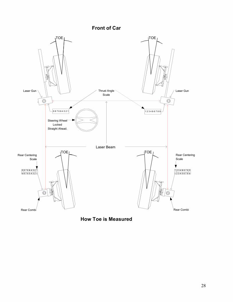
TOE
1 2 3 4 5 6 7 8 99 8 7 6 5 4 3 2 1
Laser Beam
9 8 7 6 5 4 3 2 1
9 8 7 6 5 4 3 2 1
TOE
TOE
1 2 3 4 5 6 7 8 9
1 2 3 4 5 6 7 8 9
Front of Car
How Toe is Measured
Laser Gun
Rear Combi
Rear Centering
Scale
Rear Centering
Scale
Rear Combi
Steering Wheel
Locked
Straight Ahead.
Thrust Angle
Scale
TOE
Laser Gun
29
MAINTENANCE, WARRANTY & SERVICE
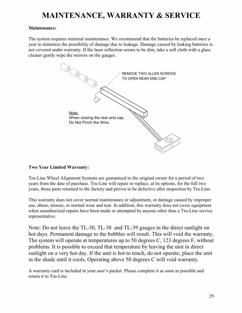
Maintenance:
The system requires minimal maintenance. We recommend that the batteries be replaced once a
year to minimize the possibility of damage due to leakage. Damage caused by leaking batteries is
not covered under warranty. If the laser reflection seems to be dim, take a soft cloth with a glass
cleaner gently wipe the mirrors on the gauges.
REMOVE TWO ALLEN SCREWS
TO OPEN REAR END CAP.
Note:
When closing the rear end cap,
Do Not Pinch the Wire.
Two Year Limited Warranty:
Tru-Line Wheel Alignment Systems are guaranteed to the original owner for a period of two
years from the date of purchase. Tru-Line will repair or replace, at its options, for the full two
years, those parts returned to the factory and proves to be defective after inspection by Tru-Line.
This warranty does not cover normal maintenance or adjustment, or damage caused by improper
use, abuse, misuse, or normal wear and tear. In addition, this warranty does not cover equipment
when unauthorized repairs have been made or attempted by anyone other than a Tru-Line service
representative.
Note: Do not leave the TL-30, TL-38 and TL-39 gauges in the direct sunlight on
hot days. Permanent damage to the bubbles will result. This will void the warranty.
The system will operate at temperatures up to 50 degrees C, 123 degrees F, without
problems. It is possible to exceed that temperature by leaving the unit in direct
sunlight on a very hot day. If the unit is hot to touch, do not operate; place the unit
in the shade until it cools. Operating above 50 degrees C will void warranty.
A warranty card is included in your user’s packet. Please complete it as soon as possible and
return it to Tru-Line.
30
SERVICE INSTRUCTIONS The user should be aware that this is a precision instrument and excessive abuse or rough
handling may result in damage and/or loss in calibration. Routine factory maintenance and
service is not necessary. However, if the system is not functioning properly, the user should not
attempt to repair any equipment. A Tru-Line service representative should perform all servicing
and repairs at the factory.
Send all repairs to with a pre-approved RMA (return merchandise authorization) to:
Tru-Line8231 Blaine Road
Blaine, WA 98230
360-371-0552
360-371-0553 fax
800-496-3777 toll free
www.Tru-Line.net