Embed Size (px)
Citation preview

1
Operating and Service Manual
Laser Wheel Alignment System
TR-12 Series
Race Car Alignment System
8231 Blaine Road
Blaine, WA 98230
360-371-0552
360-371-0553 fax
800-496-3777 Toll Free
www.Tru-Line.net
2
INTRODUCTION
The Tru-Line TR-12 Series Laser Wheel Alignment System consists of the following components:
4- TR-28 Wheel Clamps 1- TR-44 Level Compensator
1- TR-30 Easy Check Gauge 4- Frame Centering Gauges
1- TR-40 Calibration Bar (TR-12 Only) 1- Documentation
1- TR-40/212 Calibration Bar (TR-212 Only) 4- Stock car Style Hub Adapter (Optional)
1- TR-36 Left Laser Gun 1- TR-38 Left Combi Gauge (TR-12 Only)
1- TR-37 Right Laser Gun 1-TR-39 Right Combi Gauge (TR-12 Only)
1- TR-51 Calibration Laser 1- TR-52 Calibration Target Kit (TR-212 Only)
Optional components:
TR-15 Spacer Kit for Clamp TR-500 Roll Around Cart
Ninety Degree Prism Kit for Setback TR-502 Travel Case
Hub Adapters for Racecars (must be verified of type by Tru-Line)
Note: Drawings of each component is included in the procedure sections to follow.
These components are used with an alignment rack or wheel stands with a turntable in the front,
and slip plates in the rear to do an alignment. Racecars may substitute grease plates for turntables
and slip plates. No dedicated rack or level surface is required. Alignment of vehicles can be easily
done almost anywhere and the type of vehicle ranges from passenger cars to RV’s to race cars to
trucks. Many types of alignments can be done, the industry standard: two-wheel centerline, two-
wheel thrust line, and four-wheel.
All of the gauges store on the Calibration Bar, so that a complete calibration of the system can be
easily before use. The components can also be hung on a wall. Since a complete calibration only
takes a second, it is recommending that the system is calibrated before each use and recalibrated
when needed.
Tru-Line is pleased to have you and your company as a client. We are available to answer any
questions that you may have. Please feel free to contact us if there is anything further we can do to
make Tru-Line a better product for you and your company.
Tru-Line 8231 Blaine Road
Blaine, WA 98230
360-371-0552
360-371-0553 Fax
800-496-3777 Toll Free
www.Tru-Line.net
3
HOW IT WORKS
The TR-12 Series wheel alignment systems measure Caster, Camber, SAI, and Toe. Two-wheel,
Thrust angle (squaring or rear steer), and four-wheel can be done easily, with speed and accuracy.
These alignments can also be referenced to the mechanical centerline of the vehicle. Depending on
the type of vehicle being aligned, the technician chooses which alignment to do.
Although this manual presents standard two-wheel, thrust angle, and four-wheel alignment
procedures, other variations are possible. The procedures that have been laid out in the manual are
a guideline that is proven in the field. The technician can deviate from these procedures as
required.
All measuring gauges are mounted on the wheel clamps or hub adapters by hanging them on the
mounting disk, by doing if a clamp is dropped during mounting you will not damage the system
itself. The Easy Check Gauge is used to measure caster, camber and SAI on the front wheels as
well as a live caster adjustment. The two Laser Guns and two front Combi Gauges are used to
measure toe, and thrust angle (square ness or rear steer). The front Combi Gauges also measure
camber on the front wheels if the wheels only have plus or minus three degrees of camber.
Reading the Scales:
1) The toe scales are used to dial toe specifications into both Laser Boxes and both Combi
Gauges. Toe can be measured in millimeters, inches, or degrees. The toe scale is located on
the top of each Laser Box and Combi Gauge. The scale is used in conjunction with the toe
adjustment knobs and dial rings.
2) The Run-Out Scales are located on the Laser Gun Box Face. They are used in the Run-Out
procedure with the laser only.
3) The thrust angle scales are located on the Frame Centering Flags. The flags measure the
centering of the vehicle, and measure the angle of the rear axle (thrust).
4) The camber scales are located on the Easy Check Gauge and each Combi Gauge. Camber
can be measured on the four wheels.
5) The caster scale is located on the Easy Check Gauge. Caster is measured on the front
wheels. The bubble on the caster scale is adjusted with knob on the bottom right-hand
corner on the Easy Check Gauge. This scale is also used when performing run-out with the
caster / camber gauge and rim clamps.
6) The SAI scale & caster adjustment scale are located on the top of the Easy Check Gauge.
SAI is measured on the front wheels. The caster adjustment scale gives you the ability to
make a Live Caster Adjustment; the Easy Check Gauge should be locked in place with
either of these readings, which is done with the locking screw tightened onto the mounting
disk.
Note: Diagrams are included in each section.
4
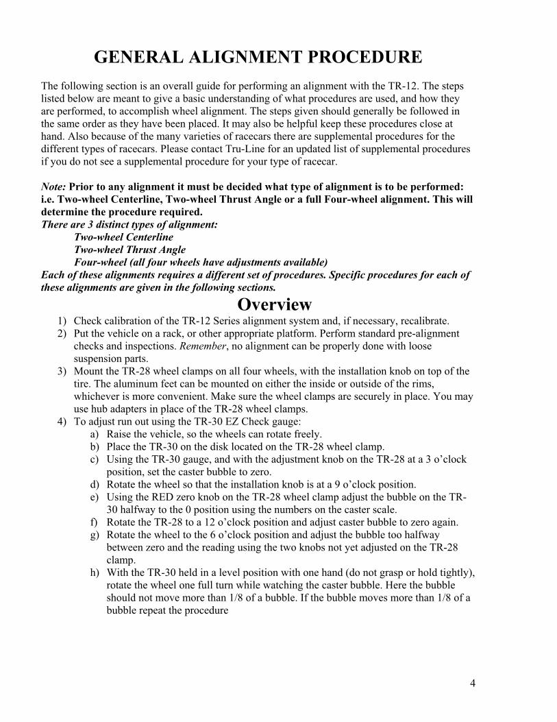
GENERAL ALIGNMENT PROCEDURE
The following section is an overall guide for performing an alignment with the TR-12. The steps
listed below are meant to give a basic understanding of what procedures are used, and how they
are performed, to accomplish wheel alignment. The steps given should generally be followed in
the same order as they have been placed. It may also be helpful keep these procedures close at
hand. Also because of the many varieties of racecars there are supplemental procedures for the
different types of racecars. Please contact Tru-Line for an updated list of supplemental procedures
if you do not see a supplemental procedure for your type of racecar.
Note: Prior to any alignment it must be decided what type of alignment is to be performed:
i.e. Two-wheel Centerline, Two-wheel Thrust Angle or a full Four-wheel alignment. This will
determine the procedure required.
There are 3 distinct types of alignment:
Two-wheel Centerline
Two-wheel Thrust Angle
Four-wheel (all four wheels have adjustments available)
Each of these alignments requires a different set of procedures. Specific procedures for each of
these alignments are given in the following sections.
Overview 1) Check calibration of the TR-12 Series alignment system and, if necessary, recalibrate.
2) Put the vehicle on a rack, or other appropriate platform. Perform standard pre-alignment
checks and inspections. Remember, no alignment can be properly done with loose
suspension parts.
3) Mount the TR-28 wheel clamps on all four wheels, with the installation knob on top of the
tire. The aluminum feet can be mounted on either the inside or outside of the rims,
whichever is more convenient. Make sure the wheel clamps are securely in place. You may
use hub adapters in place of the TR-28 wheel clamps.
4) To adjust run out using the TR-30 EZ Check gauge:
a) Raise the vehicle, so the wheels can rotate freely.
b) Place the TR-30 on the disk located on the TR-28 wheel clamp.
c) Using the TR-30 gauge, and with the adjustment knob on the TR-28 at a 3 o’clock
position, set the caster bubble to zero.
d) Rotate the wheel so that the installation knob is at a 9 o’clock position.
e) Using the RED zero knob on the TR-28 wheel clamp adjust the bubble on the TR-
30 halfway to the 0 position using the numbers on the caster scale.
f) Rotate the TR-28 to a 12 o’clock position and adjust caster bubble to zero again.
g) Rotate the wheel to the 6 o’clock position and adjust the bubble too halfway
between zero and the reading using the two knobs not yet adjusted on the TR-28
clamp.
h) With the TR-30 held in a level position with one hand (do not grasp or hold tightly),
rotate the wheel one full turn while watching the caster bubble. Here the bubble
should not move more than 1/8 of a bubble. If the bubble moves more than 1/8 of a
bubble repeat the procedure
5
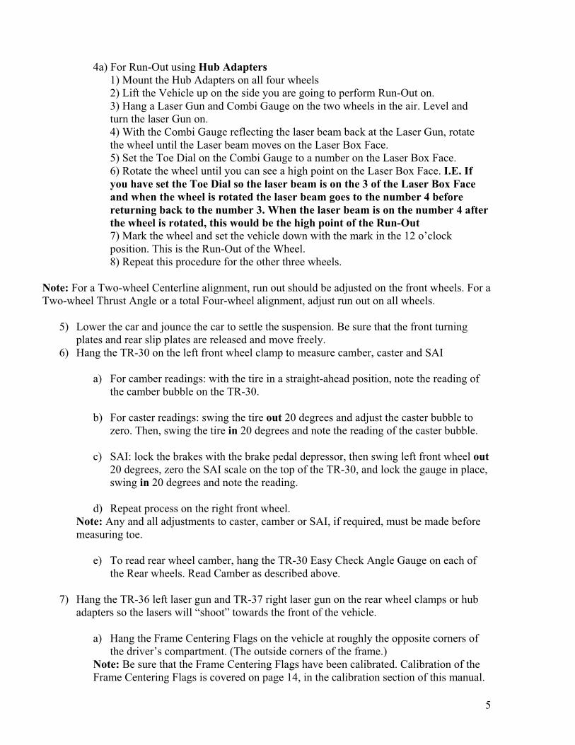
4a) For Run-Out using Hub Adapters
1) Mount the Hub Adapters on all four wheels
2) Lift the Vehicle up on the side you are going to perform Run-Out on.
3) Hang a Laser Gun and Combi Gauge on the two wheels in the air. Level and
turn the laser Gun on.
4) With the Combi Gauge reflecting the laser beam back at the Laser Gun, rotate
the wheel until the Laser beam moves on the Laser Box Face.
5) Set the Toe Dial on the Combi Gauge to a number on the Laser Box Face.
6) Rotate the wheel until you can see a high point on the Laser Box Face. I.E. If
you have set the Toe Dial so the laser beam is on the 3 of the Laser Box Face
and when the wheel is rotated the laser beam goes to the number 4 before
returning back to the number 3. When the laser beam is on the number 4 after
the wheel is rotated, this would be the high point of the Run-Out
7) Mark the wheel and set the vehicle down with the mark in the 12 o’clock
position. This is the Run-Out of the Wheel.
8) Repeat this procedure for the other three wheels.
Note: For a Two-wheel Centerline alignment, run out should be adjusted on the front wheels. For a
Two-wheel Thrust Angle or a total Four-wheel alignment, adjust run out on all wheels.
5) Lower the car and jounce the car to settle the suspension. Be sure that the front turning
plates and rear slip plates are released and move freely.
6) Hang the TR-30 on the left front wheel clamp to measure camber, caster and SAI
a) For camber readings: with the tire in a straight-ahead position, note the reading of
the camber bubble on the TR-30.
b) For caster readings: swing the tire out 20 degrees and adjust the caster bubble to
zero. Then, swing the tire in 20 degrees and note the reading of the caster bubble.
c) SAI: lock the brakes with the brake pedal depressor, then swing left front wheel out
20 degrees, zero the SAI scale on the top of the TR-30, and lock the gauge in place,
swing in 20 degrees and note the reading.
d) Repeat process on the right front wheel.
Note: Any and all adjustments to caster, camber or SAI, if required, must be made before
measuring toe.
e) To read rear wheel camber, hang the TR-30 Easy Check Angle Gauge on each of
the Rear wheels. Read Camber as described above.
7) Hang the TR-36 left laser gun and TR-37 right laser gun on the rear wheel clamps or hub
adapters so the lasers will “shoot” towards the front of the vehicle.
a) Hang the Frame Centering Flags on the vehicle at roughly the opposite corners of
the driver’s compartment. (The outside corners of the frame.)
Note: Be sure that the Frame Centering Flags have been calibrated. Calibration of the
Frame Centering Flags is covered on page 14, in the calibration section of this manual.
6
8) Determine the Total Rear Toe of the Vehicle. As described in the Two-Wheel Centerline
Alignment Procedure section of this manual which begins on page 26.
9) Determine the Thrust Angle (square ness, or rear steer) of the Vehicle. Make changes as
required. As described in the Thrust Angle Alignment Procedure section of this manual
which begins on page 29.
10) Determine the centering of the vehicle. Make Changes as required. As described in the
Two-Wheel Centerline Alignment Procedure section of this manual which begins on page
26.
11) Make Rear Toe Changes, either Total Rear Toe or Individual Toe. (If available on the
vehicle.) As described in the Four-Wheel Alignment Procedure section of this manual
which begins on page 31.
12) Remove the Frame Centering Flags.
13) Hang the TR-38 and TR-39 on the precision disks which are on either the Hub Adapters or
the Rim Clamps which are mounted on the Rear wheels, with the mirrors pointing forward
at the Laser Guns. Note: This step only for Independent Suspension Type Vehicles.
14) Determine Front Toe, and make changes as necessary. As described in the Two-Wheel
Alignment Procedure section of this manual which begins on page
15) Replace one of the Frame Centering Flags in the center position of the vehicle for Offset, if
required.
16) Place the Laser Guns on the side of the vehicle being offset. Level them turn them on and
point them at each other.
Note: For Vehicles with front toe, straighten the wheel being offset. You may also dial the
toe out of the rear wheel by adjusting the Toe Dial on the Laser Gun.
17) Determine the offset and make changes as required. As described in Determining Offset
Procedure.
7
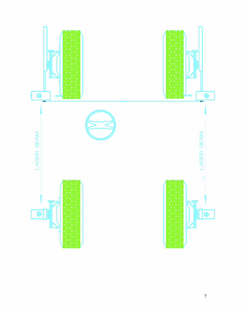
LASER BEAM
LASER BEAM
8
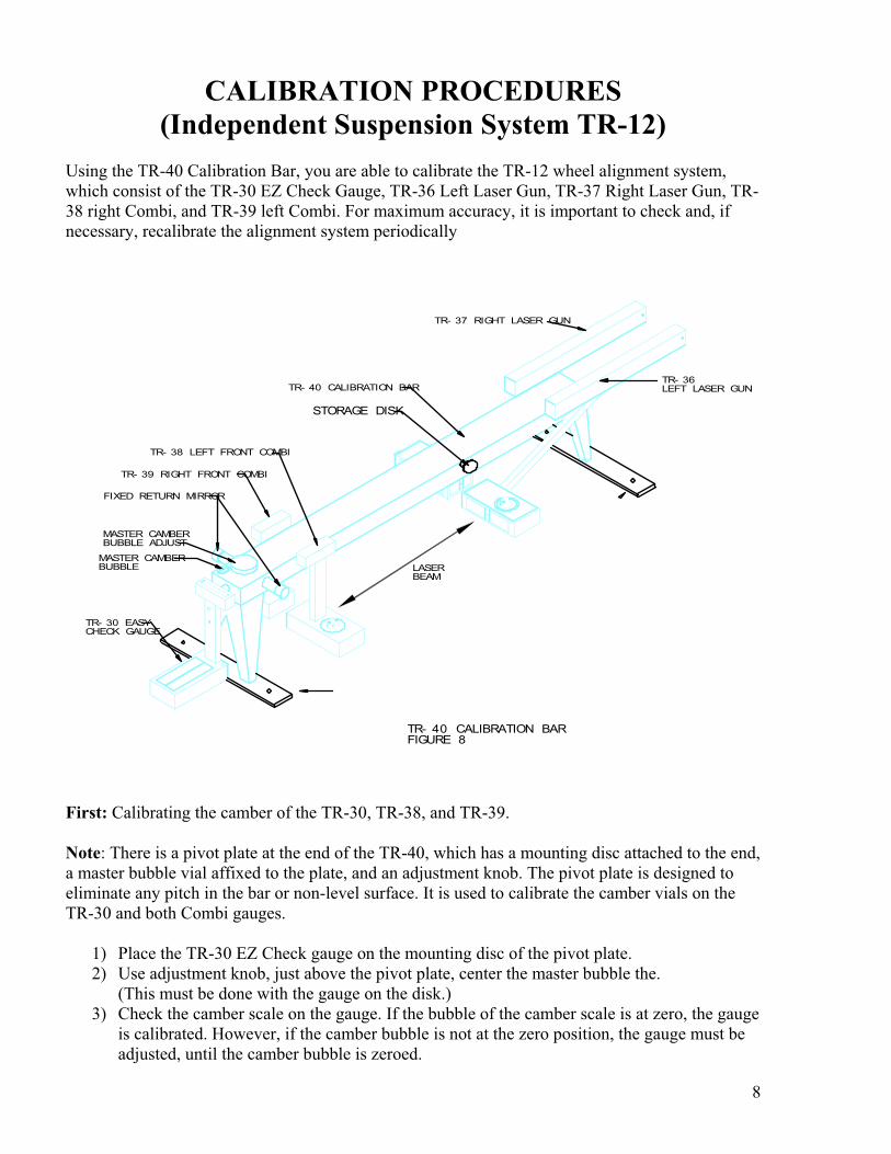
CALIBRATION PROCEDURES
(Independent Suspension System TR-12)
Using the TR-40 Calibration Bar, you are able to calibrate the TR-12 wheel alignment system,
which consist of the TR-30 EZ Check Gauge, TR-36 Left Laser Gun, TR-37 Right Laser Gun, TR-
38 right Combi, and TR-39 left Combi. For maximum accuracy, it is important to check and, if
necessary, recalibrate the alignment system periodically
TR- 36LEFT LASER GUN
TR- 37 RIGHT LASER GUN
TR- 38 LEFT FRONT COMBI
TR- 39 RIGHT FRONT COMBI
FIXED RETURN MIRROR
MASTER CAMBERBUBBLE ADJUST
MASTER CAMBERBUBBLE
TR- 30 EASYCHECK GAUGE
LASER BEAM
TR- 40 CALIBRATION BAR
STORAGE DISK
TR- 40 CALIBRATION BARFIGURE 8
First: Calibrating the camber of the TR-30, TR-38, and TR-39.
Note: There is a pivot plate at the end of the TR-40, which has a mounting disc attached to the end,
a master bubble vial affixed to the plate, and an adjustment knob. The pivot plate is designed to
eliminate any pitch in the bar or non-level surface. It is used to calibrate the camber vials on the
TR-30 and both Combi gauges.
1) Place the TR-30 EZ Check gauge on the mounting disc of the pivot plate.
2) Use adjustment knob, just above the pivot plate, center the master bubble the.
(This must be done with the gauge on the disk.)
3) Check the camber scale on the gauge. If the bubble of the camber scale is at zero, the gauge
is calibrated. However, if the camber bubble is not at the zero position, the gauge must be
adjusted, until the camber bubble is zeroed.
9
Note: It does not matter which portion of the bubble you use, the top, bottom, or middle
portion can be used with equal precision. What’s important is that once you have decided on
which part of the bubble to use, you are consistent.
a) If adjustment is needed, use the camber adjustment knob, which is in the
middle of the vertical post of the gauge
b) If a higher degree of camber is required than the scale allows you may
choose a different value to zero to. I.E. for eight degrees of positive
camber you would simply choose the negative five on the scale as your
zero.
4) Once the camber bubble is zeroed on the camber scale, calibration is complete for the
camber on that gauge.
5) Use the same procedure to calibrate each of the Combi gauges (TR-38 and TR-39). Note:
once the Combi gauges have been calibrated, place them on the two disks, which are on the
right and left side of the calibration bar and closest to the Fixed Returned Mirrors. Verify
that both Camber scales are equal and opposite.
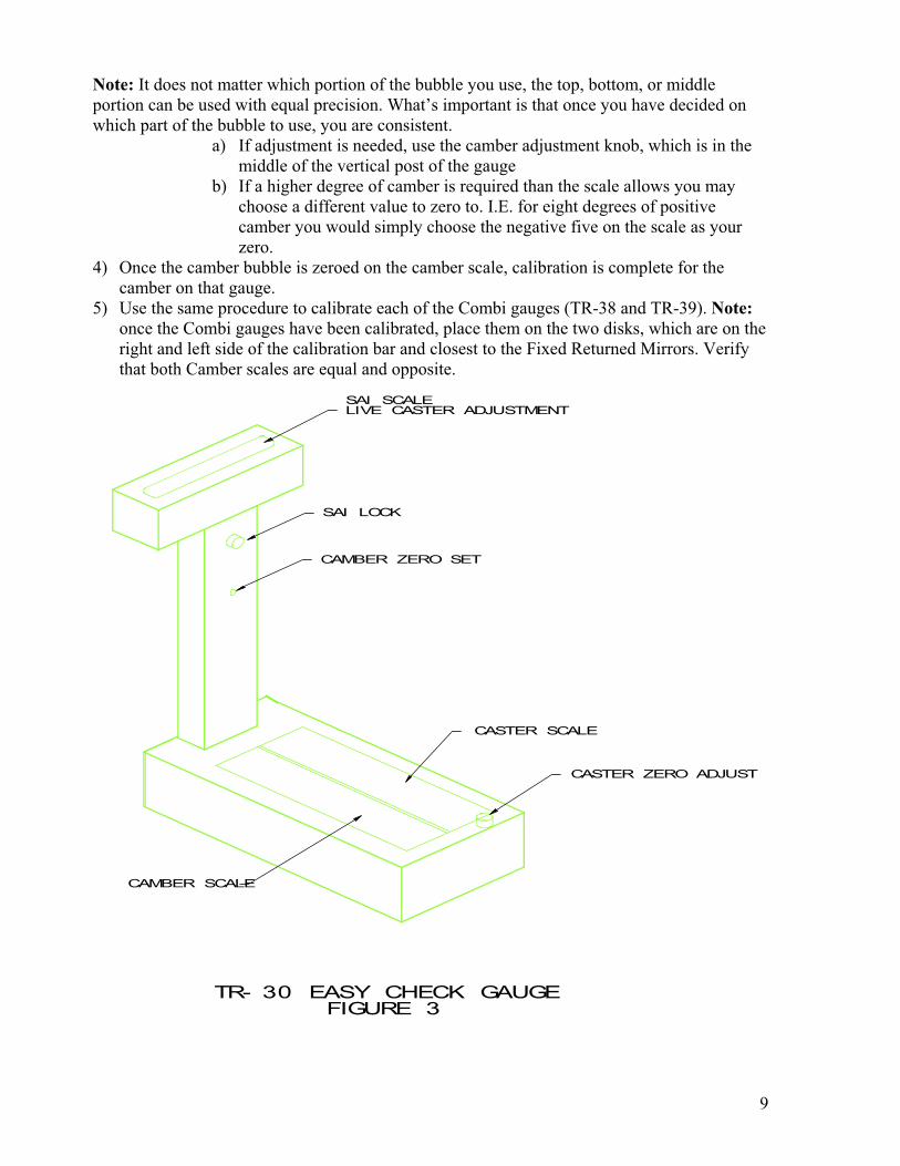
CASTER ZERO ADJUST
CASTER SCALE
CAMBER ZERO SET
SAI LOCK
SAI SCALELIVE CASTER ADJUSTMENT
CAMBER SCALE
TR- 30 EASY CHECK GAUGE FIGURE 3
10
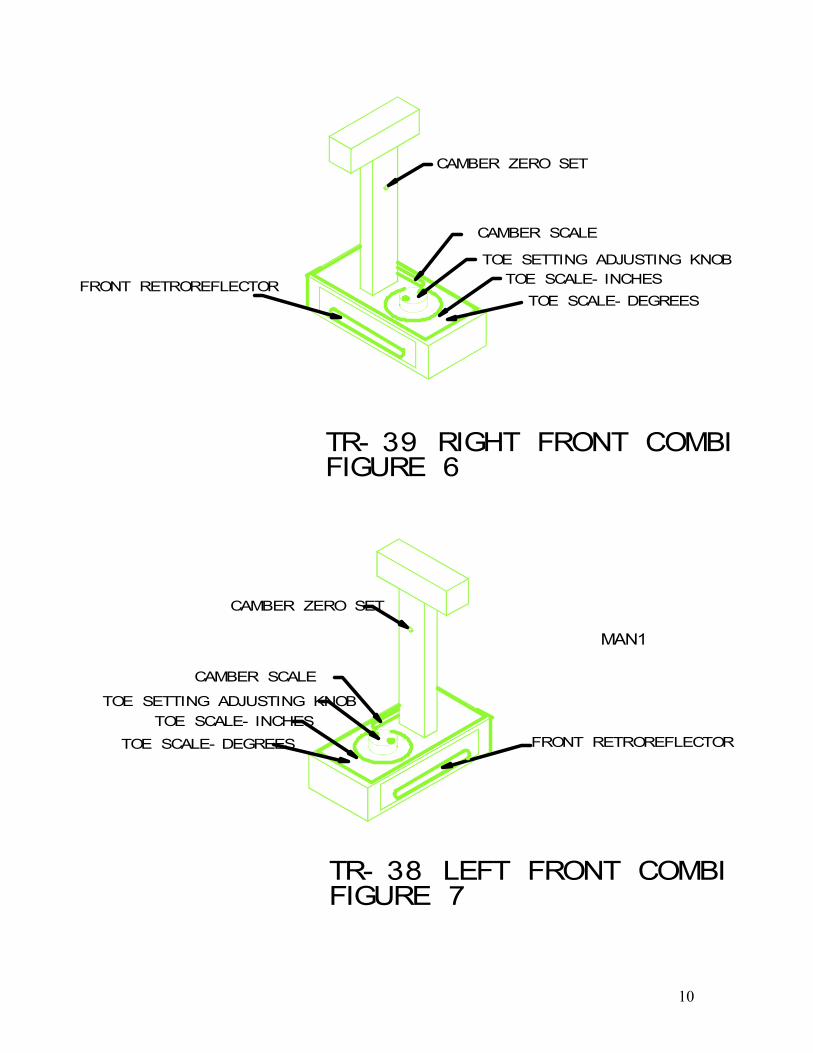
FIGURE 6TR- 39 RIGHT FRONT COMBI
FRONT RETROREFLECTOR
CAMBER ZERO SET
TOE SETTING ADJUSTING KNOB
TOE SCALE- INCHES
TOE SCALE- DEGREES
CAMBER SCALE
FRONT RETROREFLECTOR
CAMBER ZERO SET
TOE SETTING ADJUSTING KNOB
TOE SCALE- INCHES
TOE SCALE- DEGREES
CAMBER SCALE
MAN1
TR- 38 LEFT FRONT COMBIFIGURE 7
11
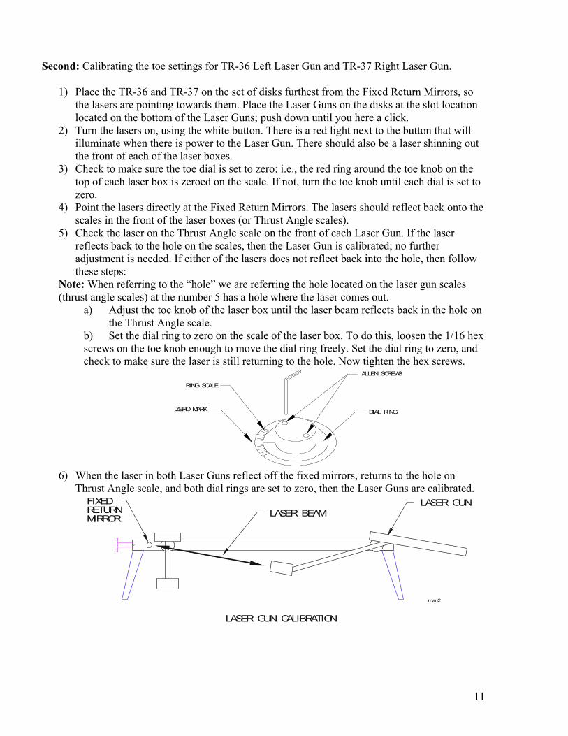
Second: Calibrating the toe settings for TR-36 Left Laser Gun and TR-37 Right Laser Gun.
1) Place the TR-36 and TR-37 on the set of disks furthest from the Fixed Return Mirrors, so
the lasers are pointing towards them. Place the Laser Guns on the disks at the slot location
located on the bottom of the Laser Guns; push down until you here a click.
2) Turn the lasers on, using the white button. There is a red light next to the button that will
illuminate when there is power to the Laser Gun. There should also be a laser shinning out
the front of each of the laser boxes.
3) Check to make sure the toe dial is set to zero: i.e., the red ring around the toe knob on the
top of each laser box is zeroed on the scale. If not, turn the toe knob until each dial is set to
zero.
4) Point the lasers directly at the Fixed Return Mirrors. The lasers should reflect back onto the
scales in the front of the laser boxes (or Thrust Angle scales).
5) Check the laser on the Thrust Angle scale on the front of each Laser Gun. If the laser
reflects back to the hole on the scales, then the Laser Gun is calibrated; no further
adjustment is needed. If either of the lasers does not reflect back into the hole, then follow
these steps:
Note: When referring to the “hole” we are referring the hole located on the laser gun scales
(thrust angle scales) at the number 5 has a hole where the laser comes out.
a) Adjust the toe knob of the laser box until the laser beam reflects back in the hole on
the Thrust Angle scale.
b) Set the dial ring to zero on the scale of the laser box. To do this, loosen the 1/16 hex
screws on the toe knob enough to move the dial ring freely. Set the dial ring to zero, and
check to make sure the laser is still returning to the hole. Now tighten the hex screws.
RING SCALE
ZERO MARK
ALLEN SCREWS
DIAL RING
6) When the laser in both Laser Guns reflect off the fixed mirrors, returns to the hole on
Thrust Angle scale, and both dial rings are set to zero, then the Laser Guns are calibrated.
LASER BEAM
LASER GUN CALIBRATION
FIXED RETURNMIRROR
LASER GUN
man2
12
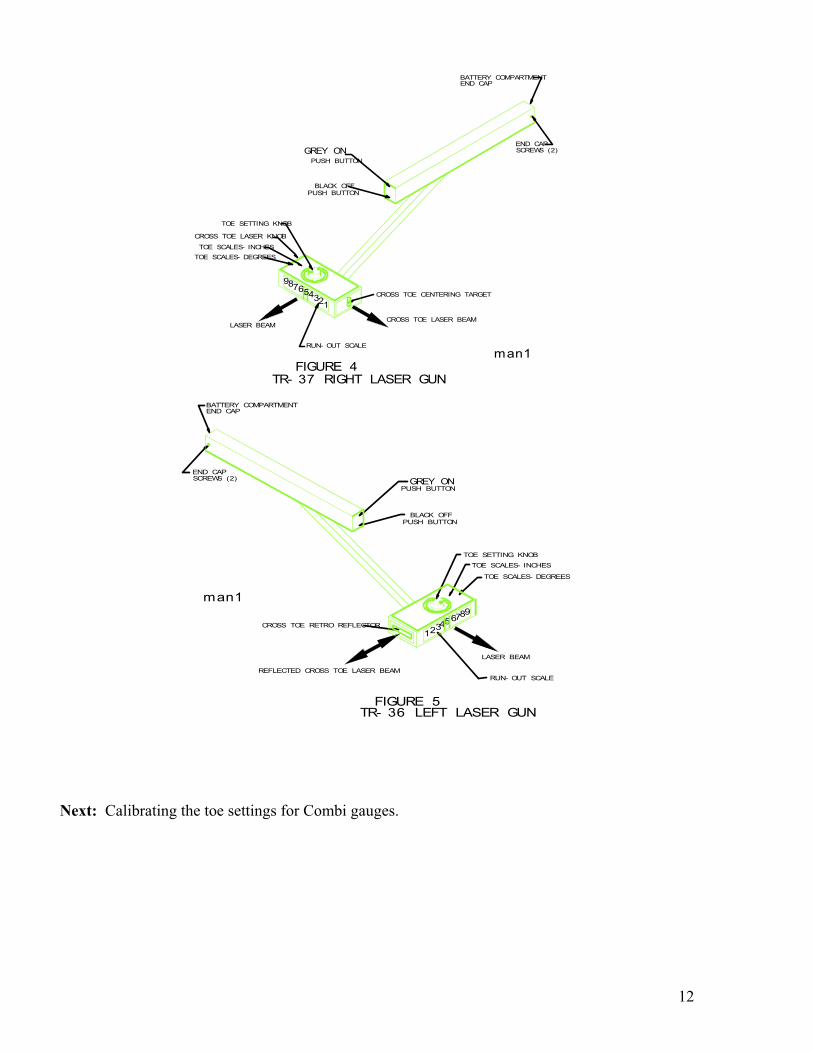
PUSH BUTTON
BLACK OFFPUSH BUTTON
TOE SETTING KNOB
TOE SCALES- DEGREES
TOE SCALES- INCHES
CROSS TOE CENTERING TARGET
RUN- OUT SCALE
LASER BEAMCROSS TOE LASER BEAM
END CAPSCREWS (2)
BATTERY COMPARTMENTEND CAP
CROSS TOE LASER KNOB
man1FIGURE 4
TR- 37 RIGHT LASER GUN
123456789
GREY ON
GREY ON
TR- 36 LEFT LASER GUNFIGURE 5
987654321
man1
REFLECTED CROSS TOE LASER BEAM
PUSH BUTTON
BLACK OFFPUSH BUTTON
TOE SETTING KNOB
TOE SCALES- DEGREES
TOE SCALES- INCHES
CROSS TOE RETRO REFLECTOR
RUN- OUT SCALE
LASER BEAM
END CAPSCREWS (2)
BATTERY COMPARTMENTEND CAP
Next: Calibrating the toe settings for Combi gauges.
13
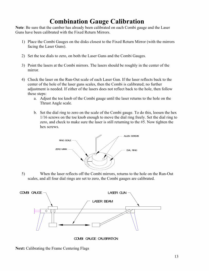
Combination Gauge Calibration Note: Be sure that the camber has already been calibrated on each Combi gauge and the Laser
Guns have been calibrated with the Fixed Return Mirrors.
1) Place the Combi Gauges on the disks closest to the Fixed Return Mirror (with the mirrors
facing the Laser Guns).
2) Set the toe dials to zero, on both the Laser Guns and the Combi Gauges.
3) Point the lasers at the Combi mirrors. The lasers should be roughly in the center of the
mirror.
4) Check the laser on the Run-Out scale of each Laser Gun. If the laser reflects back to the
center of the hole of the laser guns scales, then the Combi is calibrated; no further
adjustment is needed. If either of the lasers does not reflect back to the hole, then follow
these steps:
a. Adjust the toe knob of the Combi gauge until the laser returns to the hole on the
Thrust Angle scale.
b. Set the dial ring to zero on the scale of the Combi gauge. To do this, loosen the hex
1/16 screws on the toe knob enough to move the dial ring freely. Set the dial ring to
zero, and check to make sure the laser is still returning to the #5. Now tighten the
hex screws.
RING SCALE
ZERO MARK
ALLEN SCREWS
DIAL RING
5) When the laser reflects off the Combi mirrors, returns to the hole on the Run-Out
scales, and all four dial rings are set to zero, the Combi gauges are calibrated.
COMBI GAUGE
LASER BEAM
COMBI GAUGE CALIBRATION
LASER GUN
Next: Calibrating the Frame Centering Flags
14
Frame Centering Flag Calibration
Calibration of the Frame Centering Flags is done to ensure that we have the most accurate
theoretical centerline of the vehicle.
1) Pick the four most outside points of the frame where the Frame Centering Flags are to be
mounted on the vehicle. Making sure that each pair (near & far) is even side to side, also
decide which side of the frame the Flags are to be mounted on either the inside or the outside.
2) Next measure all four Frame Centering Flag mounting points for frame to body clearance.
3) Calibrate each of the flags to clear the vehicle body by taking a measure and straight edge
and adjusting the Frame Centering Flag Magnet Mount to an inch increment marking on the
flag scale.
Note: Attach the measure to the Magnet Mount where it will make contact with the frame.
Also when using the TR-28 Wheel Clamps, it is a good practice to include the clamp in the
Frame to Body Clearance measurement.
The ideal result is that when the Flags are mounted. Both distances between the near (those are
the flags that are closest to the Laser Guns) and far flags are the same. When this is achieved
the Flags are calibrated.
Finally: Assembly and Calibration of the TR-44 Level Compensator Bar
The TR-44 Level Compensator Bar allows you to make Caster & Camber measurements on
Non-level surfaces. Once this is calibrated and locked down there is virtually very little need to
re-calibrate it.
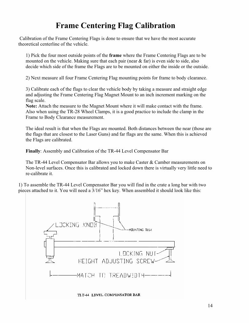
1) To assemble the TR-44 Level Compensator Bar you will find in the crate a long bar with two
pieces attached to it. You will need a 3/16” hex key. When assembled it should look like this:
15
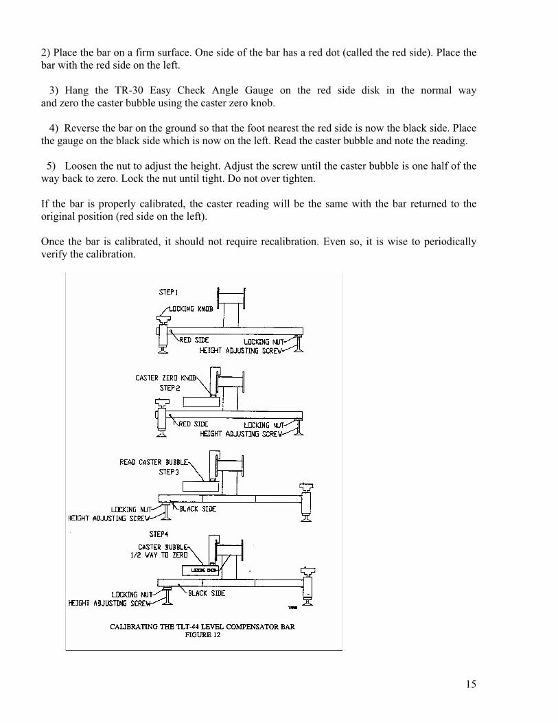
2) Place the bar on a firm surface. One side of the bar has a red dot (called the red side). Place the
bar with the red side on the left.
3) Hang the TR-30 Easy Check Angle Gauge on the red side disk in the normal way
and zero the caster bubble using the caster zero knob.
4) Reverse the bar on the ground so that the foot nearest the red side is now the black side. Place
the gauge on the black side which is now on the left. Read the caster bubble and note the reading.
5) Loosen the nut to adjust the height. Adjust the screw until the caster bubble is one half of the
way back to zero. Lock the nut until tight. Do not over tighten.
If the bar is properly calibrated, the caster reading will be the same with the bar returned to the
original position (red side on the left).
Once the bar is calibrated, it should not require recalibration. Even so, it is wise to periodically
verify the calibration.
16
CALIBRATION PROCEDURES
(Stockcar Style System TR-212)
If you own a TR-12 Stockcar System you may have already noticed that your TL-40/212
Calibration Bar looks different from the one previously shown in this manual. You may use the
calibration procedure for the TR-30 Easy Check (Caster / Camber) Gauge previously described on
pages 8 and 9 of this manual. The Frame Centering Flags and the TR-44 Level Compensator Bar
calibration can be found on pages 14 and 15 of this manual. To calibrate the TR-36 and 37 Laser
Guns follow the procedure below.
1) Place the TR-40/212 Calibration Bar on a firm surface with the long end of the bar (the side
that does not have any discs on it) pointing toward a clear area of at least twenty feet (20’).
2) Hang one of the laser guns on of the fixed discs with the laser head pointing towards the
long end of the Calibration Bar. Level the laser gun and turn it on.
3) Place the TR-52 Target Kit on a surface at least twenty (20’) feet away from the Laser Gun
on the disc that is level with the laser beam.
4) Remove the Laser Gun and replace it with the TR-51 Calibration Laser. Turn on the Cal
Laser and point it at the target.
5) Move the target so that the laser beam is on a number, I.E. the number two (2) on the
target. Once this is done remove the Cal Laser and place it on the opposite disc and point it
at the target, make note of both target readings; for example, the number two (2) from
before and the number ten and one half (10 ½).
6) Remove the Cal Laser and replace it with both laser guns on the discs, level them, turn
them on, and set the toe dials at zero (0), and adjust both camber adjustment knobs so that
the laser lines are vertical.
7) If the laser beams match the numbers from the Cal Laser then no further adjustment is
required. The Laser Guns are in calibration.
8) If the laser beams do not agree with the numbers from the Cal Laser then, adjust the toe
dials to the Cal Laser numbers, and verify that the laser beams are parallel by removing the
target from its stand and bringing it up close to the laser boxes. When both the near and far
target readings are the same, reset the toe dial by following the procedure in step 5b on
page 11 of this manual. Once this is done then the laser guns are in calibration.
17
MOUNTING TR-28 WHEEL CLAMPS
The wheel clamps can be attached to either the inside or the outside of the rim (whichever is
easiest). They can be mounted on a wheel rim 10 inches to 20 inches in diameter, and the
aluminum feet are less likely to damage polished aluminum rims.
Mounting the Wheel Clamps:
1) Adjust the installation knob either in or out until the feet will fit the wheel rim.
2) Rotate the mounting feet until they are all facing either the inside or outside of the rim.
(This depends upon which side of the rim the wheel clamps are mounted.)
3) Place the mounting feet onto the rim. Make sure they are all attached to the rim.
4) Use the installation knob to tighten the feet to the rim.
5) Make sure the mounting feet are securely on the rim. If they are not securely attached, tap
each leg with the palm of your hand and tighten the feet a little more with the installation
knob.(Repeat this process, until the mounting feet are secure.)
6) Perform the runout procedure on the appropriate wheel clamps.
Note: Although the slide plate assembly is usually centered, for a large diameter wheel, you can
loosen the locking screws and move the slide plate to the edge of wheel clamp; then, tighten the
locking screws. This will assure that the laser will shoot across the rear of the tires. Do this before
performing run out.
All the gauges are to be hung on the mounting disk of each wheel clamp. The disk does not need to
be centered on the wheel, and the wheel clamp can be at any rotation on the wheel. When the
wheel clamps have been adjusted for run out, they rotate along the same axis as the wheel.
Finally, the three knobs that are just underneath the disk are used, in conjunction with the TR-30,
to adjust for run out. The RED knob will adjust the vertical angle of the disk and, the two BLACK
knobs will adjust the horizontal angle of the disk. For example: when the adjustment knob is either
in the 12 o’clock or 6 o’clock position, use the RED knob to adjustments. Or, when the adjustment
knob is either in the 3 o’clock or 9 o’clock position, use the two BLACK knobs to make
adjustments.
Mounting the Hub Adapters
Our hub adapters mount easily to the hubs. Simply remove the dust covers from the hubs and
replace them with the hub adapters.
18
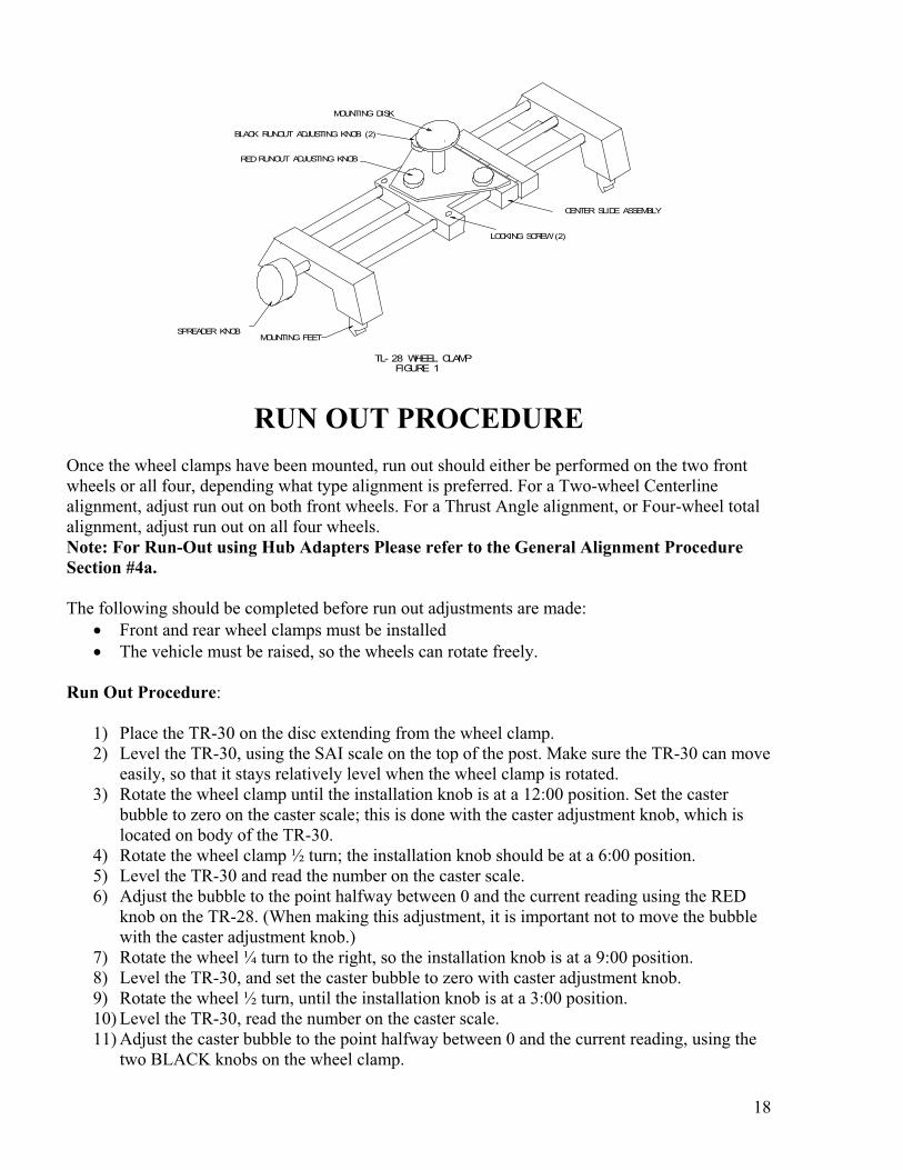
SPREADER KNOBMOUNTING FEET
CENTER SLIDE ASSEMBLY
LOCKING SCREW (2)
RUNOUT ADJUSTING KNOBRED
BLACK RUNOUT ADJUSTING KNOB (2)
MOUNTING DISK
TL- 28 WHEEL CLAMPFIGURE 1
RUN OUT PROCEDURE
Once the wheel clamps have been mounted, run out should either be performed on the two front
wheels or all four, depending what type alignment is preferred. For a Two-wheel Centerline
alignment, adjust run out on both front wheels. For a Thrust Angle alignment, or Four-wheel total
alignment, adjust run out on all four wheels.
Note: For Run-Out using Hub Adapters Please refer to the General Alignment Procedure
Section #4a.
The following should be completed before run out adjustments are made:
Front and rear wheel clamps must be installed
The vehicle must be raised, so the wheels can rotate freely.
Run Out Procedure:
1) Place the TR-30 on the disc extending from the wheel clamp.
2) Level the TR-30, using the SAI scale on the top of the post. Make sure the TR-30 can move
easily, so that it stays relatively level when the wheel clamp is rotated.
3) Rotate the wheel clamp until the installation knob is at a 12:00 position. Set the caster
bubble to zero on the caster scale; this is done with the caster adjustment knob, which is
located on body of the TR-30.
4) Rotate the wheel clamp ½ turn; the installation knob should be at a 6:00 position.
5) Level the TR-30 and read the number on the caster scale.
6) Adjust the bubble to the point halfway between 0 and the current reading using the RED
knob on the TR-28. (When making this adjustment, it is important not to move the bubble
with the caster adjustment knob.)
7) Rotate the wheel ¼ turn to the right, so the installation knob is at a 9:00 position.
8) Level the TR-30, and set the caster bubble to zero with caster adjustment knob.
9) Rotate the wheel ½ turn, until the installation knob is at a 3:00 position.
10) Level the TR-30, read the number on the caster scale.
11) Adjust the caster bubble to the point halfway between 0 and the current reading, using the
two BLACK knobs on the wheel clamp.
19
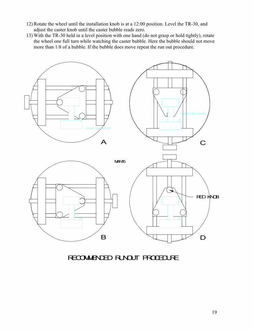
12) Rotate the wheel until the installation knob is at a 12:00 position. Level the TR-30, and
adjust the caster knob until the caster bubble reads zero.
13) With the TR-30 held in a level position with one hand (do not grasp or hold tightly), rotate
the wheel one full turn while watching the caster bubble. Here the bubble should not move
more than 1/8 of a bubble. If the bubble does move repeat the run out procedure.
A
RECOMMENDED RUNOUT PROCEDURE
CASTER ZERO ADJUST
CASTER ZERO ADJUST
RED KNOB
B
C
D
MAN15
20
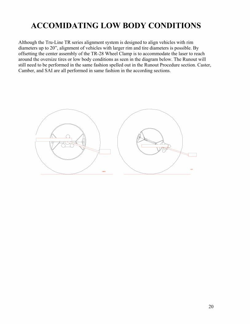
ACCOMIDATING LOW BODY CONDITIONS
Although the Tru-Line TR series alignment system is designed to align vehicles with rim
diameters up to 20”, alignment of vehicles with larger rim and tire diameters is possible. By
offsetting the center assembly of the TR-28 Wheel Clamp is to accommodate the laser to reach
around the oversize tires or low body conditions as seen in the diagram below. The Runout will
still need to be performed in the same fashion spelled out in the Runout Procedure section. Caster,
Camber, and SAI are all performed in same fashion in the according sections.
man6
man6
21
MEASURING CAMBER, CASTER, AND SAI
Measuring Caster, Camber or SAI is very simple and fast.
Before performing these measurements:
The equipment must be calibrated.
The wheel clamps must be mounted and adjusted for run out.
The full weight of the vehicle must be on its wheels
It is recommended to use turntables and slip plates when measuring caster, camber and
SAI.
The vehicle should be jounced to settle the suspension
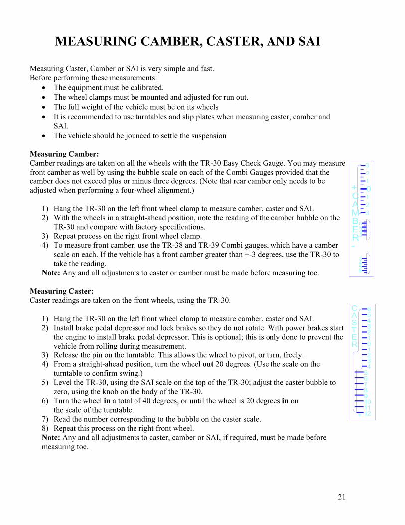
Measuring Camber:
Camber readings are taken on all the wheels with the TR-30 Easy Check Gauge. You may measure
front camber as well by using the bubble scale on each of the Combi Gauges provided that the
camber does not exceed plus or minus three degrees. (Note that rear camber only needs to be
adjusted when performing a four-wheel alignment.)
1) Hang the TR-30 on the left front wheel clamp to measure camber, caster and SAI.
2) With the wheels in a straight-ahead position, note the reading of the camber bubble on the
TR-30 and compare with factory specifications.
3) Repeat process on the right front wheel clamp.
4) To measure front camber, use the TR-38 and TR-39 Combi gauges, which have a camber
scale on each. If the vehicle has a front camber greater than +-3 degrees, use the TR-30 to
take the reading.
Note: Any and all adjustments to caster or camber must be made before measuring toe.
Measuring Caster:
Caster readings are taken on the front wheels, using the TR-30.
1) Hang the TR-30 on the left front wheel clamp to measure camber, caster and SAI.
2) Install brake pedal depressor and lock brakes so they do not rotate. With power brakes start
the engine to install brake pedal depressor. This is optional; this is only done to prevent the
vehicle from rolling during measurement.
3) Release the pin on the turntable. This allows the wheel to pivot, or turn, freely.
4) From a straight-ahead position, turn the wheel out 20 degrees. (Use the scale on the
turntable to confirm swing.)
5) Level the TR-30, using the SAI scale on the top of the TR-30; adjust the caster bubble to
zero, using the knob on the body of the TR-30.
6) Turn the wheel in a total of 40 degrees, or until the wheel is 20 degrees in on
the scale of the turntable.
7) Read the number corresponding to the bubble on the caster scale.
8) Repeat this process on the right front wheel.
Note: Any and all adjustments to caster, camber or SAI, if required, must be made before
measuring toe.
1211109876543210123456
+
RETSAC -
6543
6543
3
2
1
01
2
3
+CAMBER-
22
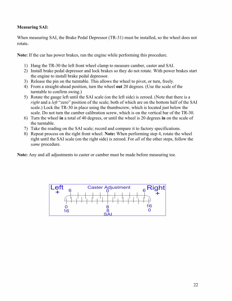
Measuring SAI:
When measuring SAI, the Brake Pedal Depressor (TR-31) must be installed, so the wheel does not
rotate.
Note: If the car has power brakes, run the engine while performing this procedure.
1) Hang the TR-30 the left front wheel clamp to measure camber, caster and SAI.
2) Install brake pedal depressor and lock brakes so they do not rotate. With power brakes start
the engine to install brake pedal depressor.
3) Release the pin on the turntable. This allows the wheel to pivot, or turn, freely.
4) From a straight-ahead position, turn the wheel out 20 degrees. (Use the scale of the
turntable to confirm swing.)
5) Rotate the gauge left until the SAI scale (on the left side) is zeroed. (Note that there is a
right and a left “zero” position of the scale; both of which are on the bottom half of the SAI
scale.) Lock the TR-30 in place using the thumbscrew, which is located just below the
scale. Do not turn the camber calibration screw, which is on the vertical bar of the TR-30.
6) Turn the wheel in a total of 40 degrees, or until the wheel is 20 degrees in on the scale of
the turntable.
7) Take the reading on the SAI scale; record and compare it to factory specifications.
8) Repeat process on the right front wheel. Note: When performing step 4, rotate the wheel
right until the SAI scale (on the right side) is zeroed. For all of the other steps, follow the
same procedure.
Note: Any and all adjustments to caster or camber must be made before measuring toe.
Left+
Right+
00
16
1688
SAI
Caster Adjustment0 66
23
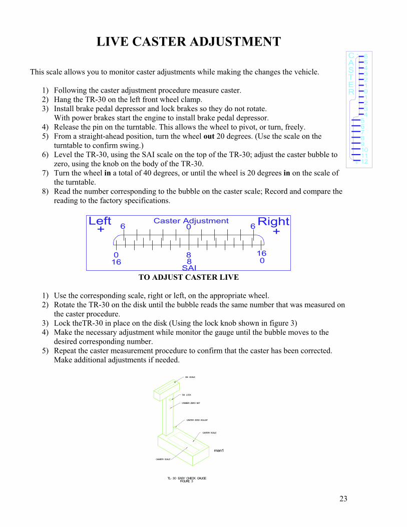
LIVE CASTER ADJUSTMENT
This scale allows you to monitor caster adjustments while making the changes the vehicle.
1) Following the caster adjustment procedure measure caster.
2) Hang the TR-30 on the left front wheel clamp.
3) Install brake pedal depressor and lock brakes so they do not rotate.
With power brakes start the engine to install brake pedal depressor.
4) Release the pin on the turntable. This allows the wheel to pivot, or turn, freely.
5) From a straight-ahead position, turn the wheel out 20 degrees. (Use the scale on the
turntable to confirm swing.)
6) Level the TR-30, using the SAI scale on the top of the TR-30; adjust the caster bubble to
zero, using the knob on the body of the TR-30.
7) Turn the wheel in a total of 40 degrees, or until the wheel is 20 degrees in on the scale of
the turntable.
8) Read the number corresponding to the bubble on the caster scale; Record and compare the
reading to the factory specifications.
Left+
Right+
00
16
1688
SAI
Caster Adjustment0 66
TO ADJUST CASTER LIVE
1) Use the corresponding scale, right or left, on the appropriate wheel.
2) Rotate the TR-30 on the disk until the bubble reads the same number that was measured on
the caster procedure.
3) Lock theTR-30 in place on the disk (Using the lock knob shown in figure 3)
4) Make the necessary adjustment while monitor the gauge until the bubble moves to the
desired corresponding number.
5) Repeat the caster measurement procedure to confirm that the caster has been corrected.
Make additional adjustments if needed.
CASTER ZERO ADJUST
CASTER SCALE
CAMBER ZERO SET
SAI LOCK
SAI SCALE
CAMBER SCALE
man1
TL- 30 EASY CHECK GAUGE FIGURE 3
1211109876543210123456
+
RETSAC -
24
MEASURING CASTER, CAMBER AND SAI ON A
NON-LEVEL SURFACE
When the vehicle is not on a level surface, the procedure is somewhat different. The TR-30 Easy
Check Angle Gauge is used in conjunction with the TR-44 Level Compensator Bar to correct the
readings. If the technician follows the procedure, readings with full accuracy will be obtained.
Even though the measurements are accurate, the ground should be reasonably near level to assure
that the vehicle suspension is not affected.
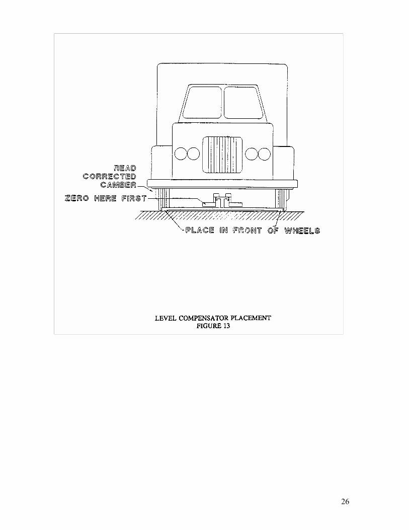
Before using the TR-44, it must be assembled and calibrated (refer to Figure 12). Figure 13 shows
the bar placed under the front wheels of the vehicle to be measured. Since the bar rests near the
front wheels, it is tilted the same amount as the vehicle. The compensation procedure that follows
corrects for the tilt. After assembly, the bar is calibrated according to the following procedure
(refer to Figure 12):
1) Mount TR-28 Wheel Clamps on front wheels, or Hub Adapters (both sides).
2) Raise wheel and adjust run-out using the standard procedure (both sides)
3) Lower wheel onto turn table and remove locking pin (both sides)
4) Place TR-44 Level Compensator Bar (that has been assembled to match the tread
width and is calibrated) in front of wheels as shown in the Figure 13.
5) Beginning on the left side, hang TR-30 Easy Check Angle Gauge on the
mounting disk on the left side of the Level Compensator Bar and adjust camber zero knob
to zero the camber bubble.
6) Measure camber on the same left of the vehicle
7) Repeat steps 5 and 6 on the right side.
Remember to zero the camber gauge each time before you measure camber.
TO MEASURE CASTER AND SAI ON A NON-LEVEL SURFACE:
To correct the caster and SAI readings, the tilt of the vehicle must be known. The following
procedures will help find these values.
TO MEASURE THE SIDE TO SIDE TILT
SAI readings are affected by the side to side tilt of the vehicle. The following procedure
compensates for the tilt to give full accuracy SAI readings. You can make the SAI readings first, or
after this procedure.
1) Place the bar in front of the wheels as shown in Figure 13 with the red side on
the right side.
25
2) Hang the gauge on the red side and zero the camber bubble using the camber zero
adjust knob (refer to Figure 3).
3) Hang the gauge on the black side and read the camber.
4) Adjust the bubble half way back using the camber zero adjust knob. The camber gauge
now reads the tilt on the ground.
5) Place the gauge on the red side and read the tilt of the ground. Whatever the
SAI readings are, add the ground tilt reading on the right side, and subtract the reading on
the left side.
TO MEASURE FRONT TO REAR TILT
Caster readings are affected by front to rear tilt of the vehicle. The following procedure
compensates for the tilt to give full accuracy caster readings. You can measure caster first by
following this procedure.
1. Place the bar along the side of the vehicle. Make sure the ground is reasonably
flat (not level) so the bar is tilting about the same as the vehicle. Place the bar on the driver
side of the vehicle with the red side toward the front.
2. Hang the gauge on the red side and zero the camber bubble using the camber zero
adjust knob (refer to Figure 3).
3. Hang the gauge on the black side and read the camber.
4. Adjust the bubble half way back using the camber zero adjust knob. The camber gauge
now reads the tilt on the ground.
5. Place the gauge on the red side and read the tilt of the ground. Whatever the caster
readings are, add the ground tilt reading to the caster reading.
26
27
TWO-WHEEL CENTERLINE ALIGNMENT
(TR-12)
The purpose of a Two-wheel Centerline alignment is to align the front wheels to the theoretical
centerline of the vehicle. This is accomplished by adjusting the front wheels to match up with the
centerline of the vehicle. Note: the Two-wheel Centerline procedure is the first step of the Thrust
Angle and Four-wheel alignments.
The following should be completed before making any measurements or adjustments:
Equipment should be checked for calibration
The full weight of the vehicle must be on its wheels
The suspension must be inspected
Front and rear wheel clamps must be installed
Runout must be completed on the front wheel clamps
Adjustments for caster, camber, and SAI should have already been completed
Note: Make sure that the steering box is in the center position and locked before loosening the
tie rods.
Two-wheel centerline alignment procedure:
1) Lock steering box in the center position. You may use the TR-32 Steering Wheel Holder to
do this.
2) Hang TR-38 and TR-39 Combi gauges on the rear wheels, with the Centering scale facing
towards the front of the vehicle. Set the toe dials to zero.
3) Hang the TR-36 and TR-37 Laser Guns on the front of the vehicle and level them; The
Laser Guns should snap into place with the laser box facing the rear of the vehicle.
4) Set the toe dials on the TR-36, TR-37, TR-38 and TR-39 to zero.
5) Adjust the cross laser on the TR-37 to hit the mirror on the TR-36 laser gun. Adjust the toe
dial on the TR-36 until the cross toe laser beam drops back into the hole on the TR-37 laser
gun.
6) Read the toe dial remembering that the Total Toe is half of what is on the Toe Dial.
7) Adjust both toe dials to reflect the Total Front Toe Reading. You now have two parallel
laser beams going down the sides of the vehicle.
8) Set the toe dials on the TR-36 & 37 laser guns to reflect the current toe condition, for
example 1/16” toe in.
9) Notice the laser beams on the combi gauges, the idea here is to have both laser beams on
the same numbers on both combi gauges.
10) To make adjustments for Front Toe you may set the toe dials equally for Total Front Toe.
For example if the desired toe is 1/8” out, set both toe dials to 1/8” toe out.
11) With the steering box locked in the center position loose the tie rods and adjust one tie rod
HALF the distance back to the hole on the TR-37 laser gun, then adjust the other tie rod the
other HALF distance back into the hole on the TR-37 laser gun.
12) Note the laser beams on the combi gauges, if the left gauge reads 7 and the right gauge
reads 5. The number for centerline would be 6 (7+5=12 divided by 2 = 6).
13) Adjust BOTH tie rods evenly to make the numbers match and the cross toe laser is still in
the hole. The Two-wheel Centerline alignment is complete when the cross-toe laser is
reflected off the cross-toe mirror back into the hole and the numbers on the Centering
scales match.
28
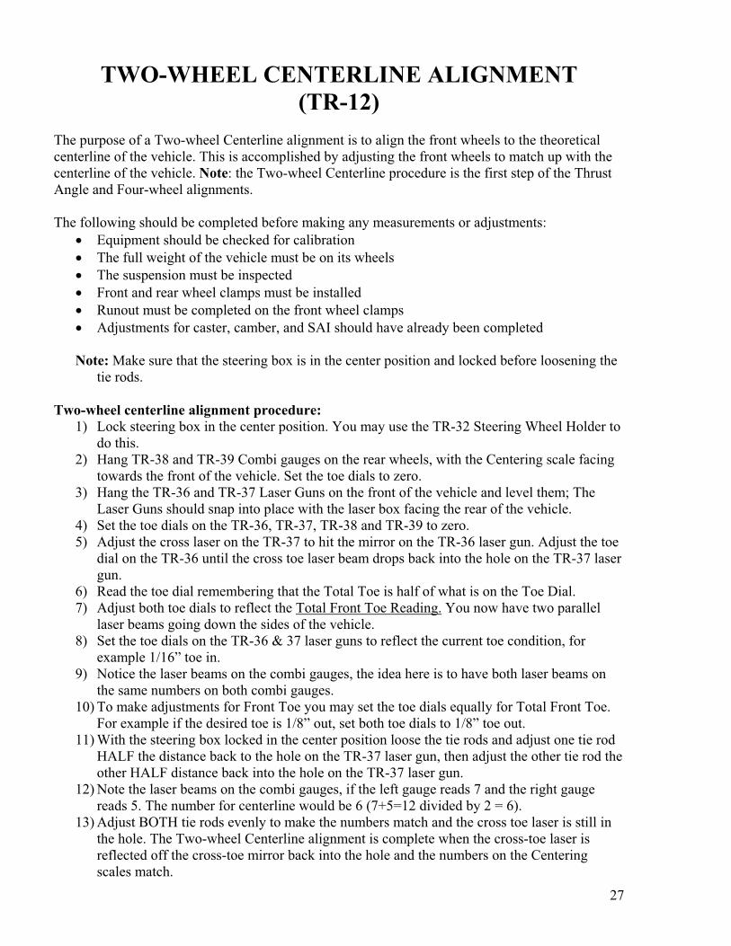
Note: when setting the dial, for example, to 1/8”, it equals a total of 1/8” overall toe or 1/16th”
on each side.
LASER BEAM
LASER BEAM
29
THRUST ANGLE ALIGNMENT
(SQUARE NESS or REAR STEER)
(TR-212)
The purpose of a Thrust Angle alignment is to adjust the rear of the vehicle to the theoretical
centerline of the vehicle. This type of alignment allows you to measure which direction the rear of
the vehicle is inclined to travel, or the thrust angle of the vehicle.
.
The following should be completed before making any measurements or adjustments:
Equipment should be checked for calibration
The full weight of the vehicle must be on its wheels
The suspension must be inspected
Front and rear wheel clamps must be installed
Runout must be completed on all wheel clamps
Adjustments for caster, camber, and SAI should have already been completed
Thrust Angle Alignment Procedure:
1) Place the TR-36 & 37 Laser Guns on the rear wheels with the lasers pointing forward on
the vehicle. Attach the frame centering flags to the four outside corners, where possible, of
the driver’s roll cage.
2) Level the laser guns turn them on and set the toe dials at zero. Adjust the cross toe laser
knob on the TR-37 laser gun so that the laser beam hits the mirror on the TR-36 laser gun.
3) Adjust the toe dial on the TR-36 until the cross toe laser beam drops back into the hole on
the TR-37 laser gun.
4) Read the toe dial remembering that the Total Toe is half of what is on the Toe Dial.
5) Adjust both toe dials to reflect the Total Rear Toe Reading. You now have two parallel
laser beams going down the sides of the vehicle.
6) Make note of the reading of the laser beams on the near flags on both sides of the vehicle.
For non offset vehicles if the readings are the same then the axle is in center on the vehicle.
If the vehicle being measured has offset, I.E. Late model stock cars, subtract the offset from
the right side near flag reading and add it to the left side reading. For example if the rights
side rear axle reading is twenty inches (20”) and the left is twelve inches (12”) and the
offset is four inches (4”). The resulting centering of the rear axle is sixteen inches (16”).
7) Now look at the far frame flags on both sides, record the difference between the near and
far flags on both sides of the vehicle.
8) Add both the difference readings together and divide them in half. This is Thrust Angle of
the vehicle. The side with the greatest difference is the direction of the Thrust Angle.
I.E. The difference Reading on the Right side is 3/8” and the difference reading on the left
side is 1/8”. Add 3/8 to 1/8 and the result is ½” divide that in half and the result is ¼”. Thus
the Thrust Angle (Square ness or Rear Steer) would be ¼” to the Right.
9) Make any adjustments as necessary.
30
31
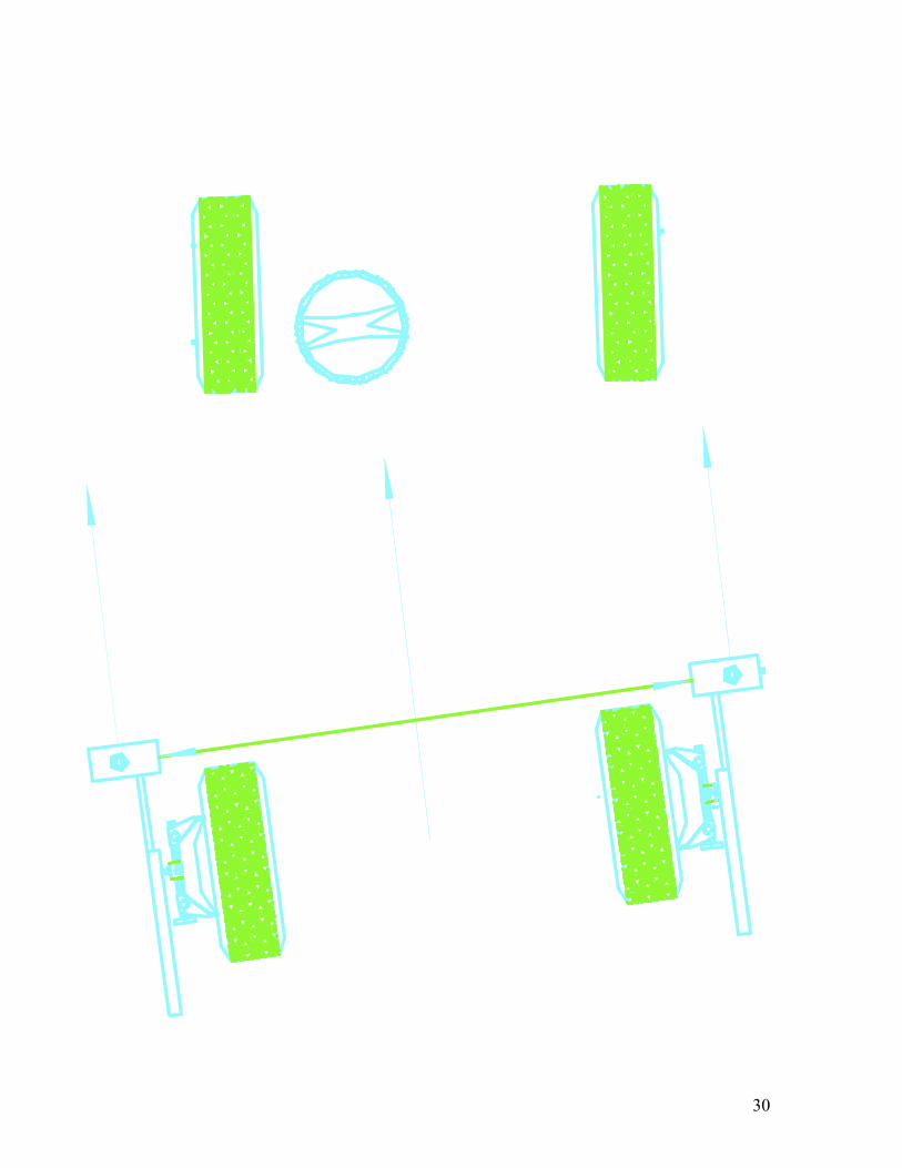
Thrust Angle for the TR-12:
After completing the two-wheel centerline procedure on page 27, use these additional steps to
complete a thrust angle alignment with the TR-12.
1) Make note of the numbers reading on the laser box face on both sides of the vehicle, I.E.
the number 8 on the left side and the number 2 on the right side.
2) Add the numbers together and divide them in half the resulting number would be 5.
3) Adjust both tie rods until the laser beams are on the number 5 on both laser box faces and
the cross toe laser is in the hole.
Setting the front Toe with the TR-212:
After completing the steps in the thrust angle alignment on page 29 of this manual, use the
following procedure to set the front toe. Remember that the Caster, Camber, and SAI must be set
before setting the front toe.
1) Center and lock the steering box. Place the TR-37 on the left front wheel pointing
towards the rear of the vehicle with the frame flags still attached to the vehicle. Level
and turn the laser gun on, adjust the laser beam so that it is vertical, compensating for
the camber. Set the toe dial at zero.
2) Note the near and far readings on the frame flags. If the readings are the same then
there is not any toe in the left front wheel, this is ideal for a circle track car.
3) Place the TR-37 back on the right side and the TR-36 on the left so that the laser guns
are in the same configuration as they were on the rear wheels.
4) Set the toe dials on the TR-36 & TR-37 at zero.
5) Adjust the cross laser on the TR-37 to hit the mirror on the TR-36 laser gun. Adjust the
toe dial on the TR-36 until the cross toe laser beam drops back into the hole on the TR-
37 laser gun.
6) Read the toe dial remembering that the Total Toe is half of what is on the Toe Dial.
7) If the toe reading is not the desired toe, then set both toe dials to the desired toe reading,
I.E. 1/8” Toe Out.
8) Adjust the tie rod on the right side until the laser beam drops back into the hole. There
is now 1/8” of toe out on the right side and the left side is at zero. A typical circle track
toe setting.
9) If a total toe condition is desired, then refer to steps 1-8 on page 27 of this manual,
make sure that the laser guns are pointed in the forward direction though.
32
FOUR-WHEEL ALIGNMENT
The objective in a Four-wheel alignment is to adjust all four wheels until they are aligned to a
specification. This alignment is typically done to vehicles that have rear wheel adjustment
available.
The following should be completed before making any measurements or adjustments:
Equipment should be checked for calibration
The full weight of the vehicle must be on its wheels turntables in the front and slip plates in
the rear.
The suspension must be inspected
Front and rear wheel clamps must be installed
Run out must be completed on the all wheel clamps
Adjustments for caster and camber should have already been completed
NOTE: Using the procedure of the TWO WHEEL CENTERLINE ALIGNMENT
section complete the additional procedures to complete a FOUR-WHEEL
ALIGNMENT.
Four-Wheel Alignment:
1) Adjust ALL Toe Dials to the desired setting.
2) Make the changes necessary until the laser beam drops back into the hole and the Laser
beams going down the sides of the vehicle are even at the combi gauges.
3) Adjust the rear suspension until the laser beams drop back into the holes on the laser
guns on both sides of the vehicle.
Note: After making all the adjustments, your objective is to all lasers dropped in the hole of the
cross toe and the thrust angle scales. We call it “Drop it in the hole, drop it in the hole and
drop in the hole. That completes a Four-Wheel Alignment.”
Import Drag Cars:
On front wheel drive drag cars, after completing the four wheel alignment. Place a pair of
frame centering flags on the rear of the wheelie bar, remove the combi gauges and use the
centering flags to adjust the wheelie bar to center.
33
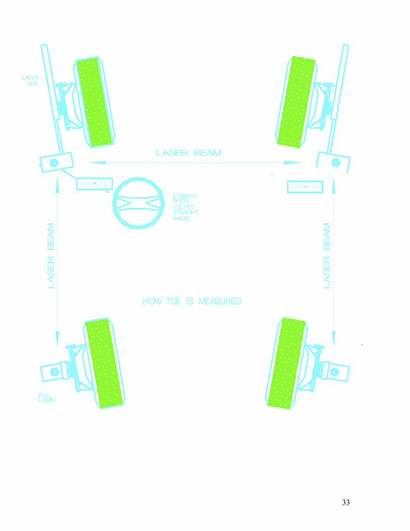
LASER BEAM
LA
SER
B
EA
M
LA
SER
B
EA
M
1 2 3 4 5 6 7 8 9 9 8 7 6 5 4 3 2 1
HOW TOE IS MEASURED
STEERINGWHEEL LOCKEDSTRAIGHT AHEAD
LASERGUN
RearCOMBI
34
Determining Offset
(TR-212) After having completed the alignment as described above many racers like to have their
right rear wheel follow the right front wheel. This is called Offset. To determine Offset
we have found this very useful.
1) Leaving the TR-37 Laser Gun in place and the toe dialed in. Take the TR-36 Laser
Gun and put on the Front Right Wheel Clamp or Hub Adapter and set the toe dial to
zero.
2) Straighten out the right front wheel by turning the steering wheel until the wheel is in
the straight ahead position.
3) Place a Frame Centering Flag at the center of the vehicle on the side that is being
Offset.
4) Level and turn on the Laser Guns so that they are pointing at each other.
5) Record the Offset at the Frame Centering Flag and make changes as necessary.
Note: If you are using Hub Adapters, you will need to put a spacer of the same
thickness on the Hub Adapter for every wheel spacer you put on.
5a) For Contact Patch Offset, take a straight edge and place it at the Laser Beam and
measure into the contact patch of the tire and record your Offset.
Note:
The TR-36 & 37 Gauges for stockcars have had the scales
changed to reflect having the gauges mounted to the car in
reverse fashion. If you place the gauges in a normal
configuration I.E. guns on the front pointing back, toe
readings will be OUT is IN and IN is OUT.
35
MAINTENANCE, WARRANTY & SERVICE
Maintenance:
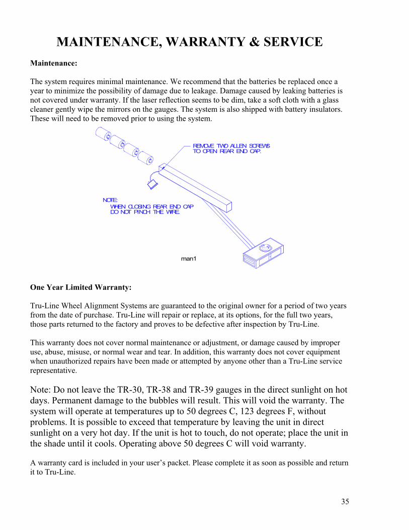
The system requires minimal maintenance. We recommend that the batteries be replaced once a
year to minimize the possibility of damage due to leakage. Damage caused by leaking batteries is
not covered under warranty. If the laser reflection seems to be dim, take a soft cloth with a glass
cleaner gently wipe the mirrors on the gauges. The system is also shipped with battery insulators.
These will need to be removed prior to using the system.
REMOVE TWO ALLEN SCREWSTO OPEN REAR END CAP.
NOTE:
WHEN CLOSING REAR END CAPDO NOT PINCH THE WIRE.
man1
One Year Limited Warranty:
Tru-Line Wheel Alignment Systems are guaranteed to the original owner for a period of two years
from the date of purchase. Tru-Line will repair or replace, at its options, for the full two years,
those parts returned to the factory and proves to be defective after inspection by Tru-Line.
This warranty does not cover normal maintenance or adjustment, or damage caused by improper
use, abuse, misuse, or normal wear and tear. In addition, this warranty does not cover equipment
when unauthorized repairs have been made or attempted by anyone other than a Tru-Line service
representative.
Note: Do not leave the TR-30, TR-38 and TR-39 gauges in the direct sunlight on hot
days. Permanent damage to the bubbles will result. This will void the warranty. The
system will operate at temperatures up to 50 degrees C, 123 degrees F, without
problems. It is possible to exceed that temperature by leaving the unit in direct
sunlight on a very hot day. If the unit is hot to touch, do not operate; place the unit in
the shade until it cools. Operating above 50 degrees C will void warranty.
A warranty card is included in your user’s packet. Please complete it as soon as possible and return
it to Tru-Line.
36
SERVICE INSTRUCTIONS
The user should be aware that this is a precision instrument and excessive abuse or rough handling
may result in damage and/or loss in calibration. Routine factory maintenance and service is not
necessary. However, if the system is not functioning properly, the user should not attempt to repair
any equipment. A Tru-Line service representative should perform all servicing and repairs at the
factory.
Send all repairs to with a pre-approved RMA (return merchandise authorization) to:
Tru-Line
8231 Blaine Road
Blaine, WA 98230
360-371-0552
360-371-0553 Fax
800-496-3777 Toll Free
www.Tru-Line.net