Embed Size (px)
Citation preview

TM 11-5820-1118-12&P
TECHNICAL MANUALOPERATOR’S AND UNIT
MAINTENANCE MANUAL"INCLUDING REPAIR PARTSAND SPECIAL TOOLS LIST
FORGROUNDING KIT, MK-2551A/U(NSN 5820-01-263-1760)RPSTL
(EIC: N/A)
PMCS
OPERATIONUNDERUSUALCONDITIONS
UNITMAINTENANCE
RPSTL
DISTRIBUTION STATEMENT A: Approved for public release; distribution is unlimited.
HEADQUARTERSDEPARTMENT OF THE ARMY
1 MAY 1994

a

WARNING
HIGH VOLTAGEis used in the operation of this equipment
DEATH ON CONTACTmay result if personnel fail to observe safety precautions
Never work on electronic equipment unless there is another person nearby who is familiar with the operation andhazards of the equipment and who is competent in administering first aid. When the technicians are aided by operators,they must be warned about dangerous areas.
Whenever possible, the power supply to the equipment must be shut off before beginning work on the equipment.Take particular care to ground every capacitor likely to hold dangerous potential. When working inside the equipment,after the power has been turned off, always ground every part before touching it.
Be careful not to contact high voltage connections or 115 volt ac input connections when installing or operating thisequipment.
Whenever the nature of the operation permits, keep one hand away from the equipment to reduce the hazard ofcurrent flowing through the body.
Warning: Do not be misled by the term "low voltage." Potentials as low as 50 volts may cause death underadverse conditions,
For Artificial Respiration, refer to FM 21 - 11b

WARNINGS
Do not attach ground to any pipe or container used for gasoline or other flammable gasses or liquids.
During thunderstorms, lightning flashover or arcing can occur between two or more unconnected or poorly connectedadjacent metal structures. Flashover can cause lethal voltage on the ground in the vicinity of these objects
LIGHTNING CAUTION FORSTAND-ALONE EQUIPMENT
When thunderstorms threaten, disconnect power from stand-alone equipment that is not sheltered by a separate lightningprotection system Then separate all such equipment by at least 6 ft or bond them together with heavy copper cable.
Do not use the MK-2551A/U for multiple vehicles or multiple equipment grounding. The MK-2551A/U is intended for singleunit applications only Do not cross power and signal cables when installing the MK-2551A/U.
CAUTION
Use gloves and safety goggles when handling and installing or removing the MK-2551A/U
NOTEDO NOT TIE the ground strap (or heavy wire substitute) to the rod or loop it around the rod. A knot or loop will greatlyreduce the effectiveness of the ground The strap must be connected by the terminal screw, a clamp, or bound with wire tothe rod.
c

TM 11-5820-1118-12&P
Technical Manual HEADQUARTERSNo 11-5820-1118-12&P DEPARTMENT OF THE ARMY,
Washington, DC, 1 May 1994
OPERATOR’S AND UNIT MAINTENANCE MANUALINCLUDING REPAIR PARTS AND SPECIAL TOOLS LIST FOR
GROUNDING KIT, MK-2551A/U(NSN 5820-01-263-1760) (EIC: N/A)
REPORTING ERRORS ANDRECOMMENDING IMPROVEMENTS
You can help improve this manual. If you find any mistakes or if you know of a way to improve theprocedures, please let us know. Mail your letter or DA Form 2028 (Recommended Changes toPublications and Blank Forms), direct to: Commander, US Army Communications-Electronics Commandand Fort Monmouth, ATTN. AMSELLC-LM-LT, Fort Monmouth, New Jersey 07703-5007.
A reply will be furnished to you.
TABLE OF CONTENTS PageCHAPTER 1 INTRODUCTION ........................................................................................ 1-1
Section I General Information ......................................................... ......................... 1-1Section II Equipment Description ..................................................... ......................... 1-3Section III Principles of Operation ..................................................... ......................... 1-4
CHAPTER 2 OPERATING INSTRUCTIONS ........................................ ......................... 2-1Section I Description and Use of Operators
Controls and Indicators .................................................... ......................... 2-1Section II Operator Preventive MaintenanceI
Checks and Services (PMCS) .......................................... ......................... 2-1Section III Operation Under Usual Conditions ................................... ......................... 2-3Section IV Operation Under Unusual Conditions . ............................. ......................... 2-5
i

CHAPTER 3 OPERATOR MAINTENANCE ............................. 3-1CHAPTER 4 UNIT MAINTENANCE ......................................... 4-1
Section I Repair Parts; Tools; Special Tools;Test, Measurement, and DiagonsticEquipment (TMDE); and, SupportEquipment ........................................................... 4-1
Section II Troubleshooting ................................................... 4-1Section III Unit Maintenance ................................................. 4-2
APPENDIX A REFERENCES .................................................... A-1APPENDIX B MAINTENANCE ALLOCATION CHART ............. B-1APPENDIX C REPAIR PARTS AND SPECIAL
TOOLS LIST ........................................................ C-1APPENDIX D COMPONENTS OF END ITEM UST .................. D-1
INDEX. ................................................................. INDEX-1ii

Grounding Kit, MK-2551A/U
(iii blank)/1-0
CHAPTER 1
INTRODUCTION
Section I. GENERAL INFORMATION
1-1. SCOPEa. Type of manual. Operator’s and Unit Maintenance Including Repair Parts and Special Tools Lists. b. Equipment name. Grounding Kit, MK-2551A/U c. Purpose of equipment. The MK-2551A/U is an alternative grounding system designed primarily for use in
tactical operations for quick installation and tear-down. It can be easily installed and removed in situationswhere using conventional grounding rods would not be possible. It does not replace the ground rod, but is anoption for use as situations or circumstances may warrant. The MK-2551A/U shall not be used as apermanent grounding system.
1-2 CONSOLIDATED INDEX OF ARMY PUBLICATIONS AND BLANK FORMS
Refer to the latest issue of DA Pam 25-30 to determine whether there are new editions, changes, or additional publicationspertaining to the equipment.
1-3. MAINTENANCE FORMS, RECORDS, AND REPORTS
a. Reports of Maintenance and Unsatisfactory Equipment. Department of the Army forms and procedures usedfor equipment maintenance will be those prescribed by DA Pam 738-750, as contained in MaintenanceManagement Update
b. Report of Packaging and Handling Deficiencies. Fill out and forward SF 364 (Report of Discrepancy (ROD))
as prescribed in AR 735-11-2/DLAR 4140 55/SECNAVINST 4355.18/AFR 400-54/MCO 4430.3J. c. Transportation Discrepancy Report (TDR) (SF361). Fill out and forward Transportation Discrepancy Report
(TDR) (SF 361) as prescribed in AR 55-38/NAVSUPINST 4610 33C/AFR 75-18/MCO P4610.19D/DLAR4500.15.
1-1

1-4 REPAIR PARTS AND SPECIAL TOOLS LIST (RPSTL)
The RPSTL is included in this manual as Appendix C.
1-5. REPORTING EQUIPMENT IMPROVEMENT RECOMMENDATIONS (EIR)
If your MK-2551A/U needs improvement, let us know. Send us an EIR. You, the user, are the only one who can tell uswhat you don’t like about your equipment. Let us know why you don’t like the design or performance. Put it on an SF 368Product Quality Deficiency Report). Mail it to: Commander, US Army Communications-Electronics Command and FortMonmouth, ATTN: AMSEL-LC-ED-CFO, Fort Monmouth, New Jersey 07703-5007. We’ll send you a reply.
1-6. DESTRUCTION OF ARMY ELECTRONICS MATERIEL
Destruction of Army electronics materiel to prevent enemy use shall be in accordance with TM 750-244-2.
1-7. ADMINISTRATIVE STORAGE
Administrative storage of equipment issued to and used by Army activities will have Preventive Maintenance Checks andServices (PMCS) performed before storing. When removing the equipment from administrative storage, the PMCSchecks should be performed to assure operational readiness.
1-8. SAFETY, CARE, AND HANDLING
Voltage step potentials created by lightning strikes may make the soil near the MK-2551A/U more hazardous than the soilsurrounding a single ground rod, since the MK-2551A/U does not penetrate deeply into the earth. This phenomena wouldbe of very short duration, similar to the strike itself. Regardless of which grounding system is used, the soil in theimmediate vicinity of the ground will be potentially dangerous during a lightning discharge. For this reason, personnelshould make every effort to seek shelter within metal enclosures, vehicles, or other relatively safe locations when electricalstorms are imminent. This same precaution applies even if a grounding system is not installed, since personnel may alsobecome a possible target for a direct strike
1-2
Section II. EQUIPMENT DESCRIPTION AND DATA
1-9. EQUIPMENT CHARACTERISTICS, CAPABILITIES, ANDFEATURES
The MK-2551A/U provides a safe path to discharge lightning, enhancing safety of personnel and equipment. It also helpsto control noise in signal circuits. The total resistance-to-ground ratio is equal to or better than that of a single ground rod,allowing the equipment to better survive a lightning strike than a single ground rod.
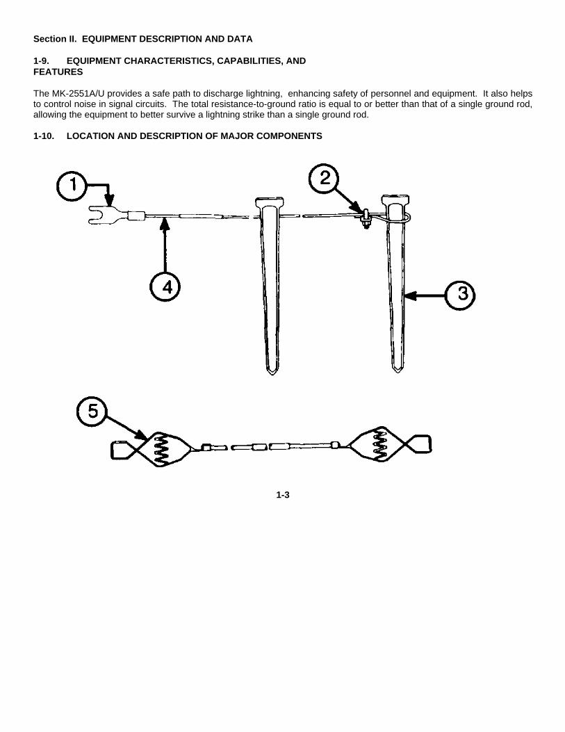
1-10. LOCATION AND DESCRIPTION OF MAJOR COMPONENTS
1-3

Table 1-1. Location of Major Components
Item Nomenclature1 Terminal lug
2 Clamp
3 Stake
4 Wire Assembly
5 Jumper Cable
1-11. EQUIPMENT DATA
The kit consists of 15 galvanized steel stakes captive on 20 meters (65 feet) of galvanized wire rope on a reel. All 15 pegsmust be driven into the earth. Each peg has a star cross section and is tapered from the top to the bottom. The completekit weighs 25 pounds, and includes a 3-pound hammer The 65-foot wire and two 10 foot jumper cables will adequatelyprotect a 5-ton truck.
Section III. PRINCIPLES OF OPERATION
1-12 THE EARTH GROUNDING SYSTEM
a Theory. An earth grounding system helps keep the electrical potential on metal surfaces at the same levelas the surrounding earth. Earth grounding also provides a discharge path for externally generated electrical surges,including lightning. An earth ground is made by electrically connecting a generator, shelter or structure to a buried metalconductor which is in con- tact with moist subsoil or reaches into the underground water table The type of groundconductor and method of installation you use depends on the climate and soil conditions of the site
b Ground rods and plates. A ground rod is generally the most effective conductor. You may get a good ground byconnecting to a buried metal object already at the site, such as a metal pipe or a steel building frame. In the desert orother places where
1-4

ground conductivity is poor, a ground plate or a group of ground rods electrically connected together will be more effectivethan a single ground rod. c Soils. Some types of soil provide better electrical grounds than others Use the type of groundconductor that works best for the soil In your location Here is a summary of soil types, grounding quality and suggestedtype of ground conductor.
QUALITY OF GROUNDTYPE OF SOIL GROUND CONDUCTORFine hard-packed Very good MK-2551A/U orsand with high Ground rodmoisture content
Clay, loam or shale Good MK-2551A/U orGround rod
Clay, loam or shale Poor MK-2551 A/U,mixed with gravel or large buriedsand; or gravel, metal object,sand or stone water pipe orground plate.
Loose gravel or Poor Large buriedsand surface metal object, wa-deeper than 6 in- ter pipe, groundches. plate or ground
rod.
Permafrost Poor Large buriedmetal object, waterpipe or MK-2551A/U if standardground rodscannot be driven.
1-5

Under very poor or poor conditions, take special steps to establish and maintain electrical conductivity, as explained inChapter 2, Section IV.
1-6

CHAPTER 2OPERATING INSTRUCTIONS
Section I. DESCRIPTION AND USE OF OPERATOR’S CONTROLS AND INDICATORS
None.Section II. OPERATOR PREVENTIVE MAINTENANCE CHECKS AND SERVICES (PMCS)
2-1 General. Preventive Maintenance Checks and Services (PMCS) means systematic caring, inspecting, andservicing of your equipment to keep it in good condition and to prevent breakdowns.
a. Be sure to perform your BEFORE (B) PMCS each time you install the grounding kit. Always do your PMCS in thesame order, so it gets to be a habit. Once you’ve had some practice, you’ll quickly spot anything wrong. Pay attention toWARNINGs, CAUTIONs, and NOTEs b. Do your DURING (D) PMCS while your equipment is actually being T operated. Pay attention to WARNINGs,CAUTIONs, and NOTEs c. Do your AFTER (A) PMCS as you are removing your grounding kit Pay attention to WARNINGs, CAUTIONs, andNOTEs d. Use DA Form 2404 (Equipment Inspection and Maintenance Worksheet) to record any faults that you discover beforeor after operation, unless you can fix them. You DO NOT need to record faults that you fix.
2-2. PMCS Proceduresa. Your Preventive Maintenance Checks and Services, Table 2-1, lists inspections and care required to keep yourgrounding kit in good operating condition. It is set up so you can do your checks in a logical order. b. The “INTERVAL” column of Table 2-1 tells you when to do a certain check or service
2-1

NOTEThe terms ’ready/available" and ’mission capable" refer to the same status: Equipment is on hand andready to perform its combat mission (See DA Pam 738750).
d. The "EQUIPMENT IS NOT READY/AVAILABLE IF:" column in Table 2-1 tells you when your grounding kit is non-mission capable and why it cannot be used e. If anything looks wrong and you can’t fix it, write it on your DA Form 2404. IMMEDIATELY report it to your supervisor. f. When you check for ’operating condition, " you look at the component to see if it’s serviceable.
Table 2-1. Preventive Maintenance Checks and Services for Grounding Kit, MK-2551A/U
Item Interval Location Procedure Not FullyNo. Item to Check/ Mission
Service Capable if:
1 Before Cable Assy Inspect Cable iscable for ob- broken,vious breaks frayed oror kinks. Re- twisted.
place orstraighten.
2 Before Clamp Inspect for Clamp iscorrosion. corroded.Clean.
3 Before Clamp Inspect for Clamp isproper con- loose.nection.Tighten
2-2

Table 2-1. Preventive Maintenance Checks and Services for Grounding Kit, MK-2551A/U - Continued
Item Interval Location Procedure Not FullyNo. Item to Check/ Mission
Service Capable if:
4 During Grounding Kit Inspect for Stakes ordamage if cable assydisturbed by are notpersonnel or firmly invehicular contact withmovement. soil andReset stakes each other.or cable.
5 After Clamp Inspect for Clamp isproper con- loose.nection.Tighten.
6 After Clamp Inspect for Clamp iscorrosion. corrodedClean.
7 After Cable Assy Inspect Cable iscable for ob- broken,vious breaks frayed oror kinks. Re- twisted.place orstraighten.
2-3
SECTION III. OPERATION UNDER USUAL CONDITIONS
2-1. ASSEMBLY AND PREPARATION FOR USE2-1.1. Installation.
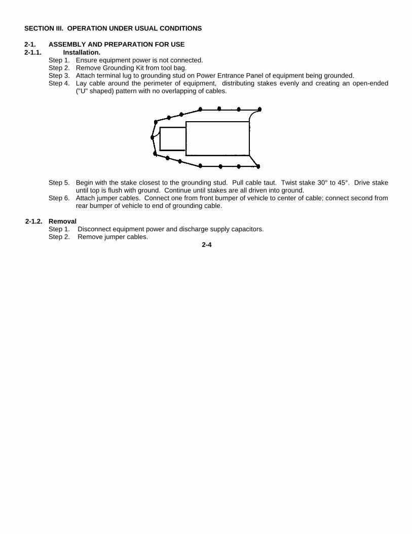
Step 1. Ensure equipment power is not connected.Step 2. Remove Grounding Kit from tool bag.Step 3. Attach terminal lug to grounding stud on Power Entrance Panel of equipment being grounded.Step 4. Lay cable around the perimeter of equipment, distributing stakes evenly and creating an open-ended
("U" shaped) pattern with no overlapping of cables.
Step 5. Begin with the stake closest to the grounding stud. Pull cable taut. Twist stake 30° to 45°. Drive stakeuntil top is flush with ground. Continue until stakes are all driven into ground.
Step 6. Attach jumper cables. Connect one from front bumper of vehicle to center of cable; connect second fromrear bumper of vehicle to end of grounding cable.
2-1.2. RemovalStep 1. Disconnect equipment power and discharge supply capacitors.Step 2. Remove jumper cables.
2-4

Step 3. Remove terminal lug from grounding stud on Power Entrance Panel.Step 4. Tap each peg from side to side using the hammer provided with the kit.Step 5. Once a peg is loosened, grasp the cable on both sides of it and pull up to remove.Step 6. Continue this procedure until all stakes are removedStep 7. Coil cables Place grounding kit and hammer in tool bag.
Section IV. OPERATION UNDER UNUSUAL CONDITIONS
2-4. UNUSUAL ENVIRONMENT/WEATHER2-4.1. Improving soil conductivity. In the event that you must ground your system in a soil that provides a poor soilconductivity (see table on page 1-5), you can take steps to improve the ground. Increase soil conductivity by adding saltand water, as shown in figure 2-1. Use water alone if salt is unavailable, Pour the water or mixture directly over the stakesof the MK-2551A/U. Clean the stakes upon removal if you use salt. Add more water daily.
Figure 2-1a. Desert.
(1) In the desert, the MK-2551A/U should work as well as a ground rod unless the sand is very loose. If thestakes of the MK-2551A/U are not secured well in the sand and are very loose, a ground rod or a ground plate may workbetter.
2-5
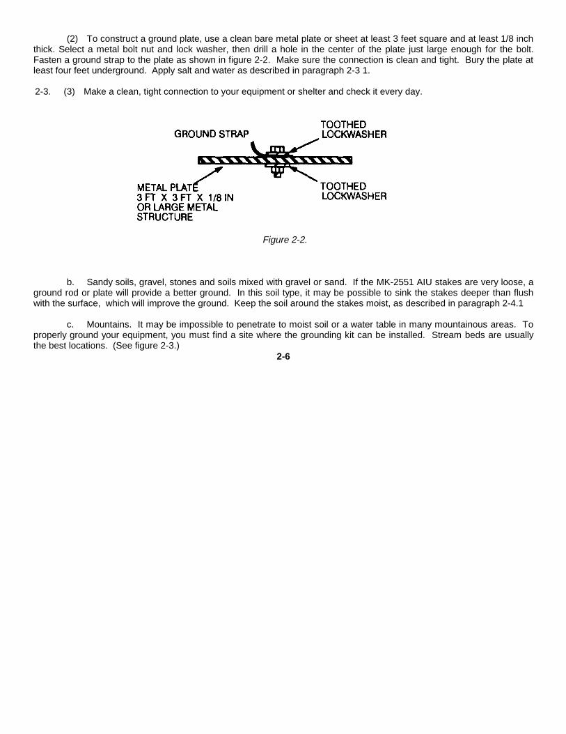
(2) To construct a ground plate, use a clean bare metal plate or sheet at least 3 feet square and at least 1/8 inchthick. Select a metal bolt nut and lock washer, then drill a hole in the center of the plate just large enough for the bolt.Fasten a ground strap to the plate as shown in figure 2-2. Make sure the connection is clean and tight. Bury the plate atleast four feet underground. Apply salt and water as described in paragraph 2-3 1.
2-3. (3) Make a clean, tight connection to your equipment or shelter and check it every day.
Figure 2-2.
b. Sandy soils, gravel, stones and soils mixed with gravel or sand. If the MK-2551 AIU stakes are very loose, a
ground rod or plate will provide a better ground. In this soil type, it may be possible to sink the stakes deeper than flushwith the surface, which will improve the ground. Keep the soil around the stakes moist, as described in paragraph 2-4.1
c. Mountains. It may be impossible to penetrate to moist soil or a water table in many mountainous areas. Toproperly ground your equipment, you must find a site where the grounding kit can be installed. Stream beds are usuallythe best locations. (See figure 2-3.)
2-6

Figure 2-3.
d. Tropics. Install the MK-2551A/U as described in paragraph 2-3. Because of the humidity, take care to keepthe strap connections clean and dry Pay special attention for corrosion. Cover the connection to the ground rod withwaterproof tape and check it every day
e. Arctic.(1) Usually in permafrost type soil, a ground rod will provide a better ground, but it may be impossible to drive the
ground rod to it’s full length. In this case, use the MK-2551A/U in accordance with paragraph 2-3. Use the soilenhancement procedures as described in paragraph 2-4.1. If frozen soil makes it difficult to drive the stakes of the MK-2551A/U into the ground, try to connect your equipment ground to a buried wa- ter pipe or other permanent buried metalstructure.
(2) Snow is essentially an insulator and will not provide a good ground connection Clear as much snow aspossible before installing the MK-2551 A/U or other grounding electrode
2-5. EMERGENCY PROCEDURESThe danger of being struck directly by lightning exists if you re- main in the open. Seek shelter. Stay as far as possiblefrom the grounding kit during electrical storm conditions.
2-7/(2-8 Blank)

CHAPTER 3
OPERATOR’S MAINTENANCE
There is no operator’s maintenance authorized for the MK-2551 A/U.
CHAPTER 4
UNIT MAINTENANCE
Section I. REPAIR PARTS; TOOLS; SPECIAL TOOLS; TEST, MEASUREMENT, AND DIAGNOSTIC EQUIPMENT(TMDE); AND, SUPPORT EQUIPMENT
4-1. COMMON TOOLS AND EQUIPMENT.
For authorized common tools and equipment, refer to the Modified Table of Organization and Equipment (MTOE), CTA50-970, or CTA 8-100, as applicable to your unit.
4-2. SPECIAL TOOLS, TMDE, AND SUPPORT EQUIPMENT.
This information is contained in Appendix C
4-3. REPAIR PARTS
This information is contained in Appendix C.
SECTION II. UNIT TROUBLESHOOTING PROCEDURES
Check for proper connections; frayed cables; loose stakes; proper installation of jumper cables.3-1/4-1

SECTION III. UNIT MAINTENANCE4-4. REMOVE AND REPLACE TERMINAL LUGMaterials ToolsTerminal Lug, Wire cuttersSC-C-681607 Tool, Crimping
Remove.Step 1. Disconnect terminal lug from ground stud and remove jumper cables.
Step 2. Using wire cutters, cut old terminal lug from cable.
Replace
Step 1. Place new terminal lug on cable.
Step 2. Using crimping tool, connect terminal lug to cable.
Step 3. Reconnect terminal lug to ground stud and replace jumper cables.
4-5. REMOVE AND REPLACE GROUND WIREMaterials ToolsWire Assembly, 65 feet Wrench, 7/16 inchSC-C-681613 Tool, Crimping
Remove.
Step 1. Disconnect terminal lug from ground stud and remove jumper cables
Step 2. Remove and retain clamp.
Step 3. Pull old cable out.
Replace
Step 1. Using crimping tool, connect terminal lug to cable.
Step 2. Thread new cable through stakes.
Step 3. Replace clamp.
Step 4. Reconnect terminal lug to ground stud and replace jumper cables.4-2

4-6. REMOVE AND REPLACE STAKES
Materials ToolsStake, Wrench, 7/16 inchSC-D-681612
Remove.
Step 1. Disconnect terminal lug from ground stud and remove jumper cables.
Step 2. Remove clamp.
Step 3. Pull cable out until damaged stake is free.
Step 4. Remove damaged stake from ground.
Replace.
Step 1. Thread cable through new stake and through remaining stakes until all stakes are reattached.
Step 2. Replace clamp.
Step 3. Drive stakes in accordance with para 2-3.
Step 4 Reconnect terminal lug to ground stud and replace jumper cables.
4-7. REPAIR JUMPER CABLESMaterials ToolsWire, Ground, 10 feet Wire cuttersSC-C-681615-1 Tool, CrimpingPC Clip, 75 Amp
Step 1. Disconnect terminal lug from ground stud and remove jumper cable(s).
Step 2. Using wire cutters, cut PC cllp(s) from cable.
Step 3. Using crimping tool, crimp PC clip(s) to cable.
Step 4. Reconnect terminal lug to ground stud and replace jumper cable(s).4-3

APPENDIX A
REFERENCES
A-1. SCOPEThis appendix lists all the forms and publications referred to in this manual.
A-2. REFERENCE LIST
AR 55-38/ Report of TransportationNAVSUPINST 4610.33C Discrepancies in Ship-AFR 75-18/ mentMCO P4610.19DDLAR 4500.15
AR 735-11-2/ Reporting of Item andDLAR 4140.55/ Packaging Discrepan-SECNAVINST 4355.18/ ciesAFR 400-54/MCO 4430 3J
DA 2028 Recommended Changesto Publications and
Blank Forms
DA PAM 25-30 Consolidated Index ofArmy Publications andBlank Forms
DA PAM 738-750 The Army MaintenanceManagement System(TAMMS)
SF 364 Report of Discrepancy(ROD)
SF 368 Product Quality Deficien-cy Report
A-3. TECHNICAL MANUALSTM 750-244-2 Destruction of Army
Electronics MaterielA-1

APPENDIX B
MAINTENANCE ALLOCATION
Section I. INTRODUCTIONB-1. GENERALThis appendix provides a summary of the maintenance operations for Grounding Kit, MK-2551A/U. It authorizes levels ofmaintenace for specific maintenance functions of repairable items and components and the tools and equipment requiredto perform each function. This appendix may be used as an aid in planning maintenance operations.
B-2. MAINTENANCE FUNCTION
Maintenance functions will be limited to and defined as follows:
a. Inspect. To determine the serviceability of an item by comparing its physical, mechanical, and/or electricalcharacteristics with established standards through examination.
b. Test. To verify serviceability and to detect incipient failure by measuring the mechanical or electricalcharacteristics of an item and comparing those characteristics with prescribed standards.
c. Service. Operations required periodically to keep an item in proper operating condition, i e., to clean(decontaminate), to preserve, to drain, to paint, or to replenish fuel, lubricants, hydraulic fluids, or compressed air sup-plies.
d. Adjust. To maintain, within prescribed limits, by bringing into proper or exact position, or by setting the operatingcharacteristics to the specified parameters.
e. Align. To adjust specified variable elements of an item to bring about optimum or desired performance.B-1

f. Calibrate. To determine and cause corrections to be made or to be adjusted on instruments or test measuringand diagnostic equipments used in precision measurement.
Consists of comparisons of two instruments, one of which is a certified standard of known accuracy, to detect and adjustany discrepancy in the accuracy of the instrument being compared.
g. Install The act of emplacing, seating, or fixing into position an item, part, module (compenent or assembly) in amanner to allow the proper functioning of the equipment or system.
h. Replace. The act of substituting a serviceable like type part, subassembly, or module (component or assembly)for an unserviceable counterpart.
i. Repair. The application of maintenance services (inspect, test, service, adjust, align, calibrate, replace) or othermaintenance actions (welding, grinding, riveting, straightening, facing, remachining, or resurfacing) to restoreserviceability to an item by correcting specific damage, fault, malfunction, or failure in a part, subassembly, module(component or assembly), end item, or system.
j. Overhaul. That maintenance effort (service/action) necessary to restore an item to a completely serviceable/operation- al condition as prescribed by maintenance standards (i.e., DMWR) in appropriate technical publications.Overhaul is normally the highest degree of maintenance performed by the Army. Overhaul does not normally return anitem to like new condition
k. Rebuild. Consists of those services/actions necessary for the restoration of unserviceable equipment to a likenew condition in accordance with original manufacturing standards Rebuild is the highest degree of materiel maintenanceapplied to Army equipment. The rebuild operation includes the act of returning to zero those age measurements (hours,miles, etc ) considered in classifying Army equipments/components
B-2

B-3. COLUMN ENTRIES
a. Column 1, Group Number. Column 1 lists group numbers, the purpose of which is to identify components,assemblies, subassemblies, and modules with the next higher assembly
b. Column 2, Component/Assembly. Column 2 contains the noun names of components, assemblies,subassemblies, and modules for which maintenance is authorized.
c. Column 3, Maintenance functions. Column 3 lists the functions to be performed on the item listed in column 2.When Items are listed without maintenance functions, it is solely for purpose of having the group numbers in the MAC andRPSTL coincide
d. Column 4, Maintenance Level. Column 4 specifies, by the listing of a "work time" figure in the appropriatesubcolumn(s), the lowest level of maintenance authorized to perform the function listed in column 3. This figurerepresents the active time required to perform that maintenance function at the indicated level of maintenance If thenumber or complexity of the tasks within the listed maintenance function vary at different maintenance levels, appropriate"work time" figures will be shown for each level. The number of task-hours specified by the "work time" figure representsthe average time required to re- store an item (assembly, subassembly, component, module, end item or system) to aserviceable condition under typical field operating conditions. This time includes preparation time, trou- bleshooting time,and quality assurance/quality control time in addition to the time required to perform the specific tasks identified for themaintenance functions authorized in the maintenance allocation chart. Subcolumns of column 4 are as follows
C Operator/Crew0 Organizational Maintenance/Aviation Unit MaintenanceF Direct Support Maintenance/Aviation Intermediate MaintenanceH General Support Maintenance
B-3

e. Column 5, Tools and Equipment. Column 5 specifies by code, those common tool sets (not individual tools) andspecial tools, test, and support equipment required to perform the designated function.
f. Column 6, Remarks. Column 6 contains an alphabetic code which leads to the remark in section IV, Remarks,which is pertinent to the item opposite the particular code.
B-4. TOOL AND TEST EQUIPMENT REQUIREMENTS (Section III)
a. Tool or Test Equipment Reference Code. The numbers in this column coincide with the numbers used in the toolsand equipment column of the MAC. The numbers indicate the applicable tool or test equipment for the maintenancefunctions.
b. Maintenance Level. The codes in this column indicate the maintenance level allocated the tool or test equipment.
c. Nomenclature. This column lists the noun name and nomenclature of the tools and test equipment required toperform the maintenance functions.
d. National/NATO Stock Number. This column lists the National/NATO stock number of the specific tool or testequip- ment.
e. Tool Number. This column lists the manufacturer’s part number of the tool followed by the Federal Supply Codefor manufacturers (5-digit) in parentheses.
B-5. REMARKS
a. Reference Code. This code refers to the appropriate item in section II, column 6.
b. Remarks. This column provides the required explanatory information necessary to clarify items appearing insection II.
B-4

Section II. MAINTENANCE ALLOCATION CHARTFOR
GROUNDING KIT, MK-2551A/U
(1) (2) (3) (4) (5) (6)
GROUP MAINTENANCEMAINTENANCE CATEGORY TOOLS AND
NUMBER COMPONENT ASSEMBLY FUNCTION C O F H D EQUIPMENTREMARKS
00 GROUNDING INSPECT .1 AKIT, INSTALL .2 1MK-2551A/U TEST .2 B5820-01-263- REPLACE .2 11760 REPAIR .5 1, 2, 3, 4
B-5

Section III. TOOL AND TEST EQUIPMENT REQUIREMENTSFOR
GROUNDING KIT, MK-2551A/U
(1) (2 ) (3) (4) (5)TOOL OR TEST
EQUIPMENT MAINTENANCE NATIONAL/NATO TOOLREF CODE LEVEL NOMENCLATURE STOCK NUMBER NUMBER
1 C, O HAMMER
2 0 WRENCH, 7/16 IN.
3 0 WIRE CUTTER
4 0 TOOL, CRIMPING
B-6

Section IV. REMARKS
REFERENCE REMARKSCODE
A Preventive Maintenance Checks and Services(PMCS).
B Visual and mechanical function of the equipment.
B-7

APPENDIX C
REPAIR PARTS AND SPECIALTOOLS LIST
C-1. SCOPE
This manual lists and authorizes spares and repair parts; special tools, special test, measurement, and diagnosticequipment (TMDE), and other special support equipment required for the performance of intermediate direct support andgeneral support maintenance of Grounding Kit, MK-2551A/U. It authorizes the requisitioning, issue, and disposition ofspares, repair parts and special tools as indicated by the source, maintenance, and recoverability (SMR) codes.
C-2. GENERAL
This Repair Parts and Special Tools List is divided into the following sections:
a. Section II. Repair Parts List. A list of spares and repair parts authorized by this RPSTL for use in theperformance of maintenance This list also includes parts which must be re- moved for replacement of the authorized parts.Parts lists are composed of functional groups in ascending item number sequence, with the parts In each group listed inascending Item number sequence. Figure numbers are listed directly beneath the group header. Bulk materials are listedin item name sequence Repair part kits are listed separately in their own functional group within Section II Repair parts forreparable special tools are also listed in this section Items listed are shown on the associated Illustration.
b. Section iii. Special Tools List. Not applicable. A list of special tools, special TMDE, and other special supportequipment authorized by this RPSTL as indicated by Basis of Issue (BOI) information in (column (5)) for the performanceof maintenance
c. Section IV. Cross-Reference Indexes. A list, in National item identification number (NIIN) sequence, of allNational stock numbered items appearing in the listing, followed by a list in
C-1

alphameric sequence of all part numbers appearing in the listings. National stock numbers and part numbers are cross-referenced to each illustration figure and item number appearance. The figure number and item number index lists figureand item numbers in numeric sequence and cross-references National stock number, Commercial and Government EntityCode, and part numbers.
C-3. EXPLANATION OF COLUMNS (Section II and III
a. Item No. (Column (1)). Indicates the number used to identify items called out in the illustrations.
b. SMR Code (Column (2)). The source, maintenance, and recoverability (SMR) code is a five-position codecontaining supply/requisitioning information, maintenance category authorization criteria and disposition instruction, asshown in the following breakout:
NOTEComplete repair: Maintenance capacity, capability, and authority to perform all corrective maintenancetasks of the "repair" function in a use/user environment in order to restore serviceability to a failed item.
C-2

(1) Source code. The source code tells you how to get an item needed for maintenance, repair, or overhaul of an enditem/equipment. Explanations of source codes follows
Code Explanation
Stocked items: use the applicable NSN torequest/requisition items with these source codes. Theyare authorized to the level indicated by the code enteredin the third position of the SMR code.
NOTE
Items coded PC are subject to deterioration.
Items with these codes are not to be requested/requisitioned individually. They are part of a kit which isauthorized to the maintenance category indicated in thethird position of the SMR code. The complete kit mustbe requisitioned and applied.
C-3

Items with these codes are not to berequested/requisitioned individually They must be madefrom bulk material which is identified by the part numberin the description and usable on (UOC) column andlisted in the Bulk Material -group of the repair parts list. Ifthe item is authorized to you by the third position code ofthe SMR code, but the source code indicates it is madeat a higher category, of maintenance.
Items with these codes are not to berequested/requisitioned individually. The parts that makeup the assembled item must be requisitioned orfabricated and assembled at the category ofmaintenance indicated by source code. If the thirdposition code of SMR code authorizes you to replace theitem, but the source code indicates the item isassembled at a higher category, order the item from thehigher category of maintenance.
C-4
Code Explanation
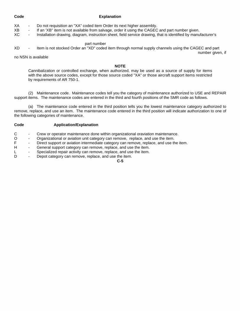
XA - Do not requisition an "XA" coded item Order its next higher assembly.XB - If an ’XB" item is not available from salvage, order it using the CAGEC and part number given.XC - Installation drawing, diagram, instruction sheet, field service drawing, that is identified by manufacturer’s
part numberXD - Item is not stocked Order an "XD" coded item through normal supply channels using the CAGEC and part
number given, ifno NSN is available
NOTECannibalization or controlled exchange, when authorized, may be used as a source of supply for itemswith the above source codes, except for those source coded "XA" or those aircraft support items restrictedby requirements of AR 750-1.
(2) Maintenance code. Maintenance codes tell you the category of maintenance authorized to USE and REPAIRsupport items. The maintenance codes are entered in the third and fourth positions of the SMR code as follows.
(a) The maintenance code entered in the third position tells you the lowest maintenance category authorized toremove, replace, and use an item. The maintenance code entered in the third position will indicate authorization to one ofthe following categories of maintenance.
Code Application/Explanation
C - Crew or operator maintenance done within organizational oraviation maintenance.O - Organizational or aviation unit category can remove, replace, and use the item.F - Direct support or aviation intermediate category can remove, replace, and use the item.H - General support category can remove, replace, and use the item.L - Specialized repair activity can remove, replace, and use the item.D - Depot category can remove, replace, and use the item.
C-5

(b) The maintenance code entered in the fourth position tells whether or not the item is to be repaired andIdentifies the lowest maintenance category with the capability to do complete repair (i.e., perform all authorized repairfunctions). This position will contain one of the following maintenance codes.
NOTESome limited repair may be done on the item at a lower category of maintenance, if authorized by theMaintenance Allocation Chart (MAC) and SMR codes.
Code ExplanationO - Organizational or aviation unit is the lowest category that can do complete repair of the item.F - Direct support or aviation intermediate is the lowest category that can do complete repaire of the item.H - General support is the lowest category that can do complete repair of the item.L - Specialized repair activity (designate the specialized repair activity) is the lowest category that can do
complete repair of the item.D - Depot is the lowest category that can do complete repair of the item.Z - Nonreparable. No repair is authorized.B - No repair is authorized. (No parts or special tools are assigned for the maintenance of a "B" coded item.)
However, the item may be reconditioned by adjusting, lubricating, etc., at the user category.
(3) Recoverability code. Recoverability codes are as- signed to items to indicate the disposition action onunserviceable items. The recoverability code is entered in the fifth position of the SMR code as follows:
Recoverability Code Application/Explanation
Z - Nonreparable item. When unserviceable, condemn and dispose of the item at the category of maintenanceshown in the third position of SMR code.
O - Reparable item. When uneconomically reparable, condemn and dispose of the item at organizationalor aviation unit category.
C-6

Recoverability Code Application/Explanation
F - Reparable item. When uneconomically reparable, condemn and dispose of the item at direct support oraviation intermediate category.
H _ Reparable item. When uneconomically reparable, condemn and dispose of the item at general supportcategory.
D - Reparable item. When beyond lower category repair capability, return to depot. Condemnation anddisposal of item not authorized below depot category.
L - Reparable item. Condemnation and disposal not authorized below specialized repair activity (SRA).A - Item requires special handling or condemnation procedures because of specific reasons (e.g., precious
metal content, high dollar value, critical material, or hazardous material. Refer to appropriate manuals/directives for specific instructions
c. CAGEC (Column (3)). The Commercial and Government Entity Code (CAGEC) is a 5-digit numeric codewhich is used to identify the manufacturer, distributor, or Government agency, etc., that supplies the item
d. Part Number (Column (4)). Indicates the primary number used by the manufacturer (individual, company,firm, corporation, or Government activity), which controls the design and characteristics of the item by means of itsengineering drawings, specifications, standards, and inspection requirements to identify an item or range of items.
NOTEWhen you use an NSN to requisition an item, the item you receive may have a different part number fromthe part ordered.
e. Description and Usable on Code (UOC) (Column (5)). This column includes the following information.
(1) The Federal item name and, when required, a mini- mum description to identify the itemC-7

(2) The physical security classification of the item is indicated by the parenthetical entry (insert applicablephysical security classification abbreviation, e.g., Phy Sec C1 (C) - Confidential, Phy Sec C1 (S) - Secret, Phy Sec C1 (T) -Top Secret)
(3) Items that are included in kits and sets are listed below the name of the kit or set.
(4) Spare/repair parts that make up an assembled item are listed immediately following the assembled item lineentry.
(5) Part numbers for bulk materials are referenced in this column in the line entry for the item to bemanufactured/fabricated.
(6 When the item is not used with all serial numbers of the same model, the effective serial numbers are shownon the last line of the description (before UOC).
(7) Usable on code, when applicable (para 5).
(8) In the Special Tools section, the basis of issue (BOI) appears as the last line in the entry for each special tool,special TMDE, and other special support equipment. When density of equipments supported exceeds density spreadindicated in the basis of issue, the total authorization is increased proportionately.
(9) The statement "END OF FIGURE" appears just below the last item description in Column (5) for a givenfigure in both section II and section III.
f. Qty (Column (6)). Indicates the quantity of the item used in the breakout shown on the illustration figure, which isprepared for a functional group, subfunctional group, or an assembly. A "V" appearing in this column in lieu of a quantityIndicates that the quantity is variable and the quantity may vary from application to application
C-4. EXPLANATION OF COLUMNS (Section IV)
a. National Stock Number (NSN) Index.
(1) Stock number column. This column lists the NSN by National item identification number (NIIN) sequence. TheNIIN consists of the last nine digits of the NSN. When using this
C-8

column to locate an item, ignore the first four digits of the NSN When requisitioning items use the complete NSN (13digits) sequence.
(2) Fig. column. This column lists the number of the figure where the item is identified/located The illustrationsare in numerical sequence In sections II and III.
(3) Item column The item number identifies the item associated with the figure listed In the adjacent Fig. column.This item is also identified by the NSN listed on the same line.
b. Part Number Index. Part numbers in this index are listed by part number in ascending alphmeric sequence.
(1) CAGEC column. This column lists the Commercial and Government Entity Code (CAGEC).
(2) Part number column. This column indicates the part number assigned to the item.
(3) Stock number column. This column lists the National stock number for the associated part number andmanufacturer identified in the part number and CAGEC columns to the left.
(4) Fig. column. This column lists the number of the figure where the item is identified/located in sections II andIll
(5) Item column. The item number is that number as- signed to the item as it appears in the figure referenced inthe adjacent figure number column.
c. Figure and Item Number Index.
(1) Fig. column. This column lists the number of the figure where the item is identified/located in sections II andIII.
(2) Item column. The item number is that number as- signed to the item as it appears in the figure referenced inthe adjacent figure number column
(3) Stock number column. This column lists the National stock number for the item
(4) CAGEC column. The Commercial and Government Entity Code (CAGEC) is a 5-digit numeric code used toidentify the manufacturer, distributor, or Government agency, etc., that supplies the item.
C-9

(5) Part number column. Indicates the primary number used by the manufacturer (individual, firm, corporation, orGovernment activity), which controls the design and characteristics of the item by means of its engineering drawings,specifications, standards, and inspection requirements to identify an item or range of items.
C-5. SPECIAL INFORMATION
a. Usable on Code. The usable on code appears in the lower left corner of the description column heading. Usableon code- sare shown as ’UOC:" in the description column justified left) on the first line applicable item descriptionnomenclature. Uncoded items are applicable to all models Identification of the usable on codes used in this RPSTL are:
Code Used on
N/A N/A
b. Fabrication Instructions. Bulk materials required to manufacture items are listed in the bulk material functionalgroup of this RPSTL. Part numbers for bulk materials are also referenced in the description column of the line item entryfor the item to be manufactured/fabricated Detailed fabrication instructions for items source coded to be manufactured orfabricated are not applicable.
c. Assembly Instructions. Detailed assembly instructions for items source coded to be assembled from componentspare/ repair parts are found in xxxxxxxxxxxxxxxx. Items that make up the assembly are listed immediately following theassembly item entry or reference is made to an applicable figure.
d. Kits. Line item entries for repair part kits appear in a group in section II (refer to table of contents).
e. Index Numbers. Items which have the word BULK in the figure column will have an index number shown in theitem number column. This index number is a cross-reference between the National Stock Number/Part Number Index andthe bulk material list In section II.
C-10

f. Associated Publications, The publications listed below pertains to the MK-2551A/U and its components:
NONE
g. Illustrations Listing. Not applicable.
h. National Stock Numbers. National stock numbers (NSN’s) that are missing from P source coded items have beenapplied for and will be added to this TM by future change/revision when they are entered in the Army Master Data File(AMDF). Until the NSN’s are established and published, submit exception requisitions to: Commander, US ArmyCommunications-Electronics Command and Fort Monmouth, ATTN: AMSELLC-MM, Fort Monmouth, NJ 07703-5007 forthe part required to support your equipment.
C-6. HOW TO LOCATE REPAIR PARTS
a. When National stock number or part number is not known.
(1) First Using the table of contents, determine the assembly group or subassembly group to which the itembelongs. This is necessary since figures are prepared for assembly groups and subassembly groups, and listings aredivided into the same groups.
(2) Second. Find the figure covering the assembly group or subassembly group to which the item belongs.
(3) Third. Identify the item on the figure and note the item number.
(4) Fourth. Refer to the Repair Parts Lists for the figure to find the part number for the item number noted onthe figure.
C-11

(5) Fifth. Refer to the Part Number Index to find the NSN, if assigned.
b. When National stock number or part number is known.
(1) First. Using the index of National stock numbers and part numbers, find the pertinent National stocknumber or part number. The NSN index is in National item identification number (NIIN) sequence (para 4a(1)). The partnumbers in the part number index are listed in ascending alphameric sequence (para 4b). Both indexes cross-referenceyou to the illustration figure and item number of the item you are looking for.
(2) Second. After finding the figure and item number, verify that the item is the one you’re looking for, thenlocate the item number in the repair parts list for the figure.
C-7. ABBREVIATIONS
Not applicable.C-12

Figure 1. Group 00: MK-2551 A/U (sheet 1 of 2)C-13

Figure 1. Group 00: MK-2551A?U (Sheet 20f 2)C-14

(1) (2) (3) (4) (5) (6)ITEM SMR PARTNO CODE CAGEC NUMBER DESCRIPTION AND USABLE ON CODE (UOC) QTY
00 GROUNDING KIT, MK-2551A/UFIGURE 1
1 PAOZZ 80063 SC-C-681607 Terminal, Lug 12 PAOZZ 19207 856468 Rope, Wire V3 PAOZZ 80063 SC-D-681612 Stake, Guy 154 PAOZZ 96906 MS16842-2 Clamp, Wire Rope, SAD 15 PAOZZ 80063 SM-B-540574 Clip, Electrical 26 PAOZZ 26916 33A271 Hammer, Hand 17 PAOZZ 34623 11655979 Bag, Tool, Satchel 18 PAOZZ 96906 MS3367-3 Strap, Tiedown Elect 19 PAOZZ 80063 SC-C-681614 Sheet, Technical 1
END OF FIGUREC-15

CROSS REFERENCE INDEXES
FIGURE AND ITEM NUMBER INDEX
FIG. ITEM STOCK NUMBER CAGEC PART NUMBER
C-1 1 5940-01-383-0447 80063 SC-C-681607
C-1 2 4010-00-032-2938 19207 856468
C-1 3 4030-01-383-6690 80063 SC-D-681612
C-1 4 4030-00-233-9567 96906 MS16842-2
C-1 5 5999-00-832-4373 80063 SM-B-540574
C-1 6 5120-00-203-4656 26916 33A271
C-1 7 5140-00-473-6256 34623 11655979
C-1 8 5975-01-273-8133 96906 MS3367-3
C-1 9 7610-01-385-2947 80063 SC-C-681614
C-16

CROSS-REFERENCE INDEXES
PART NUMBER INDEX
CAGEC PART NUMBER STOCK NUMBER FIG. ITEM
96906 MS16842-2 4030-00-233-9567 C-1 4
96906 MS3367-3 5975-01-273-8133 C-1 8
80063 SC-C-681607 5940-01-383-0447 C-1 1
80063 SC-C-681614 7610-01-385-2947 C-1 9
80063 SC-D-681612 4030-01-383-6690 C-1 3
80063 SM-B-540574 5999-00-832-4373 C-1 5
34623 11655979 5140-00-473-6256 C-1 7
26916 33A271 5120-00-203-4656 C-1 6
19207 856468 4010-00-032-2938 C-1 2
C-17

CROSS- REFERENCE-INDEXES
NATIONAL STOCK NUMBER INDEX
STOCK NUMBER FIG. ITEM STOCK NUMBER FIG. ITEM
4010-00-032-2938 C-1 2
5120-00-203-4656 C-1 6
4030-00-233-9567 C-1 4
5140-00-473-6256 C-1 7
5999-00-832-4373 C-1 5
5975-01-273-8133 C-1 8
5940-01-383-0447 C-1 1
4030-01-383-6690 C-1 3
7610-01-385-2947 C-1 9
C-18

APPENDIX D
COMPONENTS OF END ITEM LISTSection I. INTRODUCTION
D-1. SCOPE
This appendix lists integral components of and basic issue items for the TK-2551AJU to help you inventory items requiredfor safe and efficient operation.
D-2. GENERAL
This Components of End Item List is divided into the following sections:
a. Section II. Integral Components of the End Item. These items, when assembled, comprise the TK-2551A/Uand must accompany it whenever it is transferred or turned in. The illustrations will help you identify these items.
b. Section III. Basic Issue Item. Not applicable.
D-3. EXPLANATION OF COLUMNS
a. Illustration. This column is divided as follows:
(1) Figure number. Indicates the figure number of the illustration on which the item is shown.
(2) Item number. The number used to identify item called out in the illustration.
b. National Stock Number. Indicates the National stock number assigned to the item and which will be used forrequisitioning.
c. Description. Indicates the federal item name and, if required, a minimum description to identify the item. Thepart number indicates the primary number used by the manufacturer, which controls the design and characteristics of theitem by means of its engineering drawings, specifications, standards, and inspection requirements to identify an item orrange of items. Following the part number, the Commercial and Govern- ment Entity Code (CAGEC) is shown inparentheses.
D-1

d. Location. The physical location of each item listed is given in this column. The lists are designed to inventory allitems in one area of the major item before moving on to an adjacent area.
e. Usable on Code. Not applicable. "USABLE ON" codes are included to help you identify which component itemsare used on the different models. Identification of the codes used in these lists are:
Code Used on
N/A N/A
f. Quantity Required (Qty Reqd). This column lists the quantity of each item required for a complete major item.
g. Quantity. This column is left blank for use during an inventory. Under the Rcvd column, list the quantity youactually receive on your major item. The Date columns are for your use when you inventory the major item.
D-2

Figure D-.1 Components of End Item (Sheet 1 of 2)D-3

Figure D- 4. Components of End Item (Sheet 2 of 2)D-4

(1) (2) (3) (4) (5)NATIONAL
ILLUS STOCK DESCRIPTION, Usable QTYNUMBER NUMBER CAGEC and Part Number On Code U/M Reqd
1 Ground Wire Assembly 12 Short, Ground Wire Assembly 23 Hammer, Double Face 14 Bag, Tool, Satchel 1
D-5/(D-6 blank)

APPENDIX E
INDEX
Title PageNo.
AAdministrative Storage ................................................................................................................................................ 1-2Assembly and Preparation for Use .............................................................................................................................. 2-4
CCommon Tools and Equipment . ................................................................................................................................ 4-1Components of End Item List ...................................................................................................................................... D-1
D
Description and Use of Operator’s Controls and Indicators ........................................................................................ 2-1Destruction of Army Electronics Materiel .................................................................................................................... 1-2
E
Earth Grounding System ............................................................................................................................................. 1-4Emergency Procedures ............................................................................................................................................... 2-7Equipment Characteristics, Capabilities and Features................................................................................................. 1-3Equipment Data ........................................................................................................................................................... 1-4
F
Ground Wire, Remove and Replace ........................................................................................................................... 4-2I
Index of Army Pubs and Blank Forms ......................................................................................................................... 1-1J
Jumper Cables, Remove, Replace and Repair ........................................................................................................... 4-2L
Location and Description of Major Components ......................................................................................................... 1-3
Index-1

Title PageNo.
L - continued
Lubrication Instructions ............................................................................................................................................... 4-1M
Maintenance Allocation ............................................................................................................................................... B-1Maintenance Allocation Chart ...................................................................................................................................... B-5Maintenance Forms, Records, and Reports ............................................................................................................... 1-1
O
Operator Preventive Maintenance Checks and Services (PMCS) .............................................................................. 2-1Operator’s Maintenance .............................................................................................................................................. 3-1Operation Under Usual Conditions .............................................................................................................................. 2-4Operation Under Unusual Conditions .......................................................................................................................... 2-5
R
References .................................................................................................................................................................. A-1Remove and Replace Stakes ...................................................................................................................................... 4-2Terminal Lug ............................................................................................................................................................... 4-2Ground Wire ................................................................................................................................................................ 4-2Repair Jumper Cables ................................................................................................................................................. 4-2Repair Parts and Special Tools List ............................................................................................................................ C-1Reporting Equipment Improvement .............................................................................................................................
Recommendations (EIR) ................................................................................................................................ 1-2S
Safety, Care, and Handling ......................................................................................................................................... 1-2Scope ........................................................................................................................................................................... 1-1
Index-2

Title PageNo.
S - continued
Special Tools, TMDE, and Support Eqiupment ................................................................................................................................................................................................................................................................................................. 4-1Stakes, Remove and Replace ........................................................................................................................................................................................................................................................................................................................... 4-2
T
Terminal Lug, Remove and Replace ........................................................................................................................... 4-2U
Unusual Environment/Weather ................................................................................................................................... 2-5Unit Maintenance ......................................................................................................................................................... 4-1,
4-2Unit Troubleshooting Procedures................................................................................................................................. 4-1
Index-3


THE METRIC SYSTEM AND EQUIVALENTS

PIN: 072562-000

This fine document...
Was brought to you by me:
Liberated Manuals -- free army and government manuals
Why do I do it? I am tired of sleazy CD-ROM sellers, who take publicly available information, slap “watermarks” and other junk on it, and sell it. Those masters of search engine manipulation make sure that their sites that sell free information, come up first in search engines. They did not create it... They did not even scan it... Why should they get your money? Why are not letting you give those free manuals to your friends?
I am setting this document FREE. This document was made by the US Government and is NOT protected by Copyright. Feel free to share, republish, sell and so on.
I am not asking you for donations, fees or handouts. If you can, please provide a link to liberatedmanuals.com, so that free manuals come up first in search engines:
<A HREF=http://www.liberatedmanuals.com/>Free Military and Government Manuals</A>
– SincerelyIgor Chudovhttp://igor.chudov.com/