Embed Size (px)
Citation preview
TM 11-6665-230-34
TECHNICAL MANUAL
DIRECT SUPPORT AND GENERAL SUPPORT
MAINTENANCE MANUAL
RADIAC SET AN/PDR-27R(NSN 6665-00-961-0846)
HEADQUARTERS, DEPARTMENT OF THE ARMY
3 SEPTEMBER 1984
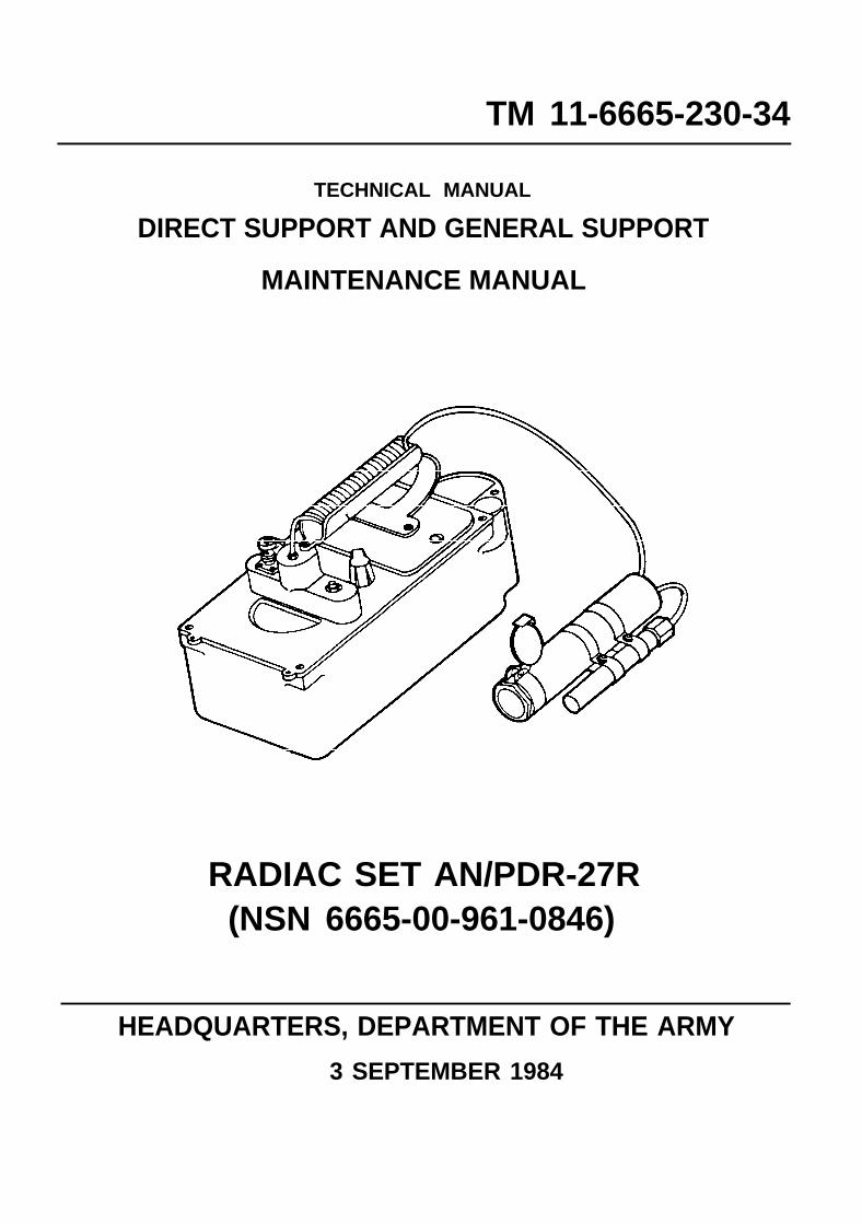
DANGER
TM 11-6665-230-34
WARNING
HIGH VOLTAGE
DEATH ON CONTACT
Be careful when working on this equipment.The high voltage power supply produces 680 volts dc.
KRYPTON 85
The Radioactive Test Sample MX-7338/PDR-27 contains 5 millicuries of KRYPTON 85. Damage to bodytissue can result from mishandling.
Refer to TM 3-6665-264-10 for specific instructions on control, safe handling, inspection, storage anddisposition of the test sample.
A
TM 11-6665-230-34
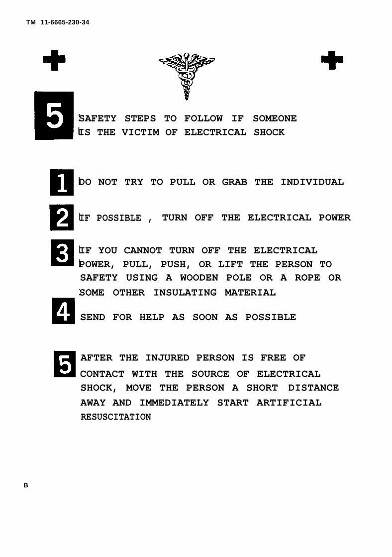
SAFETY STEPS TO FOLLOW IF SOMEONEIS THE VICTIM OF ELECTRICAL SHOCK
DO NOT TRY TO PULL OR GRAB THE INDIVIDUAL
IF POSSIBLE , TURN OFF THE ELECTRICAL POWER
IF YOU CANNOT TURN OFF THE ELECTRICALPOWER, PULL, PUSH, OR LIFT THE PERSON TOSAFETY USING A WOODEN POLE OR A ROPE ORSOME OTHER INSULATING MATERIAL
SEND FOR HELP AS SOON AS POSSIBLE
AFTER THE INJURED PERSON IS FREE OFCONTACT WITH THE SOURCE OF ELECTRICALSHOCK, MOVE THE PERSON A SHORT DISTANCEAWAY AND IMMEDIATELY START ARTIFICIALRESUSCITATION
B
Technical Manual
No. 11-6665-230-34
CHAPTERSection
*TM 11-6665-230-34
HEADQUARTERS
DEPARTMENT OF THE ARMYWashington, DC, 3 September 1984
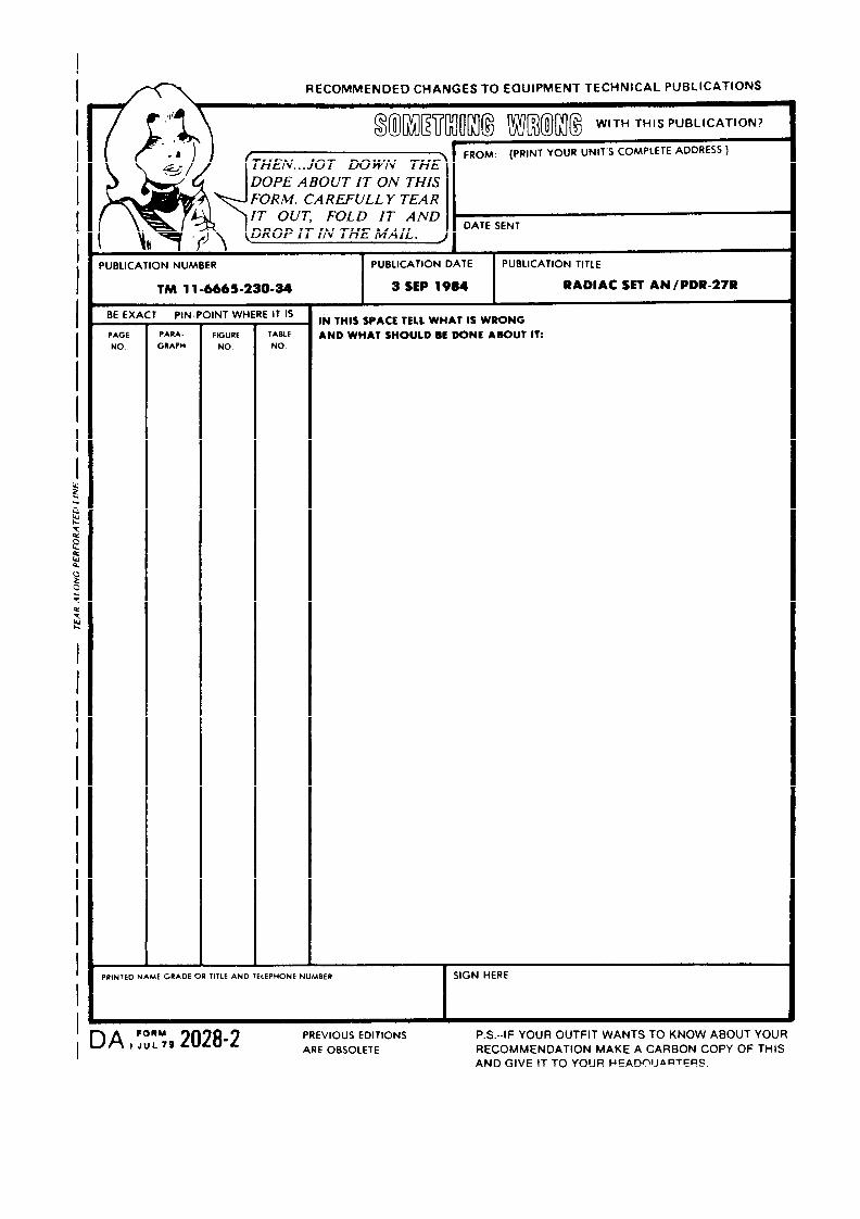
REPORTING ERRORS AND RECOMMENDING IMPROVEMENTS
You can help improve this manual. If you find any mistakes or if you knowof a way to improve the procedures, please let us know. Mail your letter, DAForm 2028 (Recommended Changes to Publications and Blank Forms), orDA Form 2028-2 located in back of this manual direct to: Commander, USArmy Communications-Electronics Command and Fort Monmouth, ATTN:DRSEL-ME-MP, Fort Monmouth, New Jersey 07703-5007. In either case, a replywill be furnished direct to you.
APPENDIX
DIRECT SUPPORT AND GENERAL SUPPORTMAINTENANCE MANUAL
RADIAC SET AN/PDR-27R(NSN 6665-00-961-0846)
CHAPTER 1Section I
IIIII
2I
IIIIIIV
ABC
DE
HOW TO USE THIS MANUAL . . . . . . . . . . . . . . . . . . . . . . . . . . . . . . . . . . .INTRODUCTION . . . . . . . . . . . . . . . . . . . . . . . . . . . . . . . . . . . . . . . . . . . . . .General Information . . . . . . . . . . . . . . . . . . . . . . . . . . . . . . . . . . . . . . . . . .Equipment Description and Data.. . . . . . . . . . . . . . . . . . . . . . . . . . . . . . .Technical Principles of Operation . . . . . . . . . . . . . . . . . . . . . . . . . . . . . . .
GENERAL SUPPORT MAINTENANCE. . . . . . . . . . . . . . . . . . . . . . . . . . . .General Information . . . . . . . . . . . . . . . . . . . . . . . . . . . . . . . . . . . . . . . . . . .Troubleshooting . . . . . . . . . . . . . . . . . . . . . . . . . . . . . . . . . . . . . . . . . . . . . .Maintenance Procedures . . . . . . . . . . . . . . . . . . . . . . . . . . . . . . . . . . . . . .General Test Requirements.. . . . . . . . . . . . . . . . . . . . . . . . . . . . . . . . . . .
REFERENCES . . . . . . . . . . . . . . . . . . . . . . . . . . . . . . . . . . . . . . . . . . . . . . .MAINTENANCE ALLOCATION (Nonapplicable)COMPONENTS OF END ITEM AND BASIC ISSUE ITEMS LIST
(Not Applicable)ADDITIONAL AUTHORIZATION LIST (Not Applicable)EXPENDABLE SUPPLIES AN D MATERIALS LIST . . . . . . . . . . . . . . . . . .
GLOSSARY . . . . . . . . . . . . . . . . . . . . . . . . . . . . . . . . . . . . . . . . . . . . . . . . . .
FOLDOUT INDEX . . . . . . . . . . . . . . . . . . . . . . . . . . . . . . . . . . . . . . . . . . . . .
Pageiii1-11-11-21-4
2-12-12-32-82-9
A-1
E-1
E-2
E-2
*This manual, together with, TM 11-6665-230-12, 3 September 1984, supersedes TM 11-6665-230-15, 20 June1967, including all changes.
i
TM 11-6665-230-34
LIST OF ILLUSTRATIONS
Figure Title Page
1-1 Radiac Set AN/PDR-27R . . . . . . . . . . . . . . . . . . . . . . . . . . . . . . . . . . . . . . . . . . . . 1-01-2 Radiac Set AN/PDR-27R, Functional Block Diagram . . . . . . . . . . . . . . . . . . . . 1-32-1 Low Voltage Assembly, 1A1, Component and Test Point Locations . . . . . . . 2-62-2 High Voltage Assembly, 1A2, Component and Test Point Locations . . . . . . . 2-7
LIST OF TABLES
Number Title Page
2-1 Troubleshooting . . . . . . . . . . . . . . . . . . . . . . . . . . . . . . . . . . . . . . . . . . . . . . . . . . 2-42-2 Transistor Voltage . . . . . . . . . . . . . . . . . . . . . . . . . . . . . . . . . . . . . . . . . . . . . . . . 2-5
ii
TM 11-6665-230-34
HOW TO USE THIS MANUAL
● This manual describes the General Support maintenance function only.
● Direct Support maintenance is not applicable.
● Chapters, sections, paragraphs and tables are listed in numeric sequence.
● Pay particular attention to all WARNINGS and CAUTIONS appearing in this manual.
iii
TM 11-6665-230-34
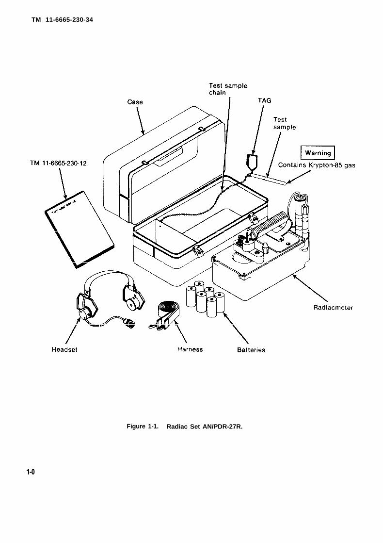
Figure 1-1. Radiac Set AN/PDR-27R.
1-0
TM 11-6665-230-34
CHAPTER 1
INTRODUCTION
Section I. GENERAL INFORMATION
1-1. Scopea. This manual describes general support maintenance for Radiac Set, AN/PDR-27R. It includes in-
structions for troubleshooting, repairing and testing the equipment. It also lists all the tools, test equip-ment, and materials required for maintenance and calibration.
b. Radiac Set AN/PDR-27R detects beta radiation and measures and detects gamma nuclear radia-tion. Operating instructions and organizational maintenance is covered in TM 11-6665-230-12.
1-2. Consolidated Index of Publications and Blank FormsRefer to the latest issue of DA PAM 310-1 to determine whether there are new editions, changes or addi-tional publications pertaining to this equipment.
1-3. Maintenance Forms, Records, and Reportsa. Reports. of Maintenance and Unsatisfactory Equipment. Department of the Army forms and pro-
cedures used for equipment maintenance will be those prescribed by DA PAM 738-750, The ArmyMaintenance Management System (TAM MS) as contained in Maintenance Management Update.
b. Report of Packaging and Handling Deficiencies. Fill out and forward SF 364 (Report of Discrepancy(ROD)) as prescribed in AR 735-11-2/DLAR 4240.55/NAVMATlNST 4355.73A/AFR 400-54/MCO 4430.3F.
c. Discrepancy in Shipment Report (DISREP) (SF 361). Fill out and forward Discrepancy in ShipmentReport (DISREP) (SF 361) as prescribed in AR 55-38/NAVSUPlNST 4610.33C/AFR 75-18/MCO P4610.19D/-DLAR 4500.15.
1-4. CalibrationRadiac Set AN/PDR-27R will require calibration using Calibrator Set, Radiac AN/UDM-2. The applicablecalibration procedure is located in TM 11-6665-227-12 (Strontium-90).
1-5. Destruction of Army Electronics MaterielDestruction of Army electronics materiel to prevent enemy use shall be in accordance with TM 750-244-2.
1-6. Administrative StorageAdministrative Storage of equipment issued to and used by Army activities will have preventivemaintenance performed in accordance with the PMCS charts before storing (TM 11-6665-230-12). Whenremoving the equipment from administrative storage the PMCS should be performed to assure opera-tional readiness. Disassembly and repacking of equipment for shipment or limited storage are covered inTM 11-6665-230-12.
1-7. Reporting Equipment Improvement Recommendations (EIR)If your Radiac Set AN/PDR-27R needs improvement, let us know. Send us an EIR. You, the user, are theonly one who can tell us what you don’t like about your equipment. Let us know why you don’t like thedesign. Put it on an SF 368 (Quality Deficiency Report). Mail it to Commander, US Army Communications-Electronics Command and Fort Monmouth, ATTN: DRSEL-ME-MP, Fort Monmouth, New Jersey 07703-5007.We’ll send you a reply.
1-8. Nomenclature Cross Reference ListSee TM 11-6665-230-12.
1-1
DANGER
TM 11-6665-230-34
Section II. EQUIPMENT DESCRIPTION AND DATA
1-9. Equipment Purpose, Capabilities, and FeaturesSee TM 11-6665-230-12.
1-10. Location and Description of Major ComponentsSee TM 11-6665-230-12.
1-11. Differences in ModelsRadiac Set AN/PDR-27R is similar in appearances to Radiac Sets AN/PDR-27J, AN/PDR-27L, AN/PDR-27Pand AN/PDR-27Q, and performs the same functions. It differs from these models only in its internal cir-cuitry.
1-12. Equipment DataSee TM 11-6665-230-12.
1-13. Safety Care and Handling
WARNING
The test sample used in this equipment is radioactive. Damage to body tissuecan result from mishandling.
● Do not remove the test sample from the chain attaching it to the carryingcase.
● Do not handle the test sample by the radioactive end (purple end).● Do not prolong exposure to the radiation and handle the test sample
unprotected.
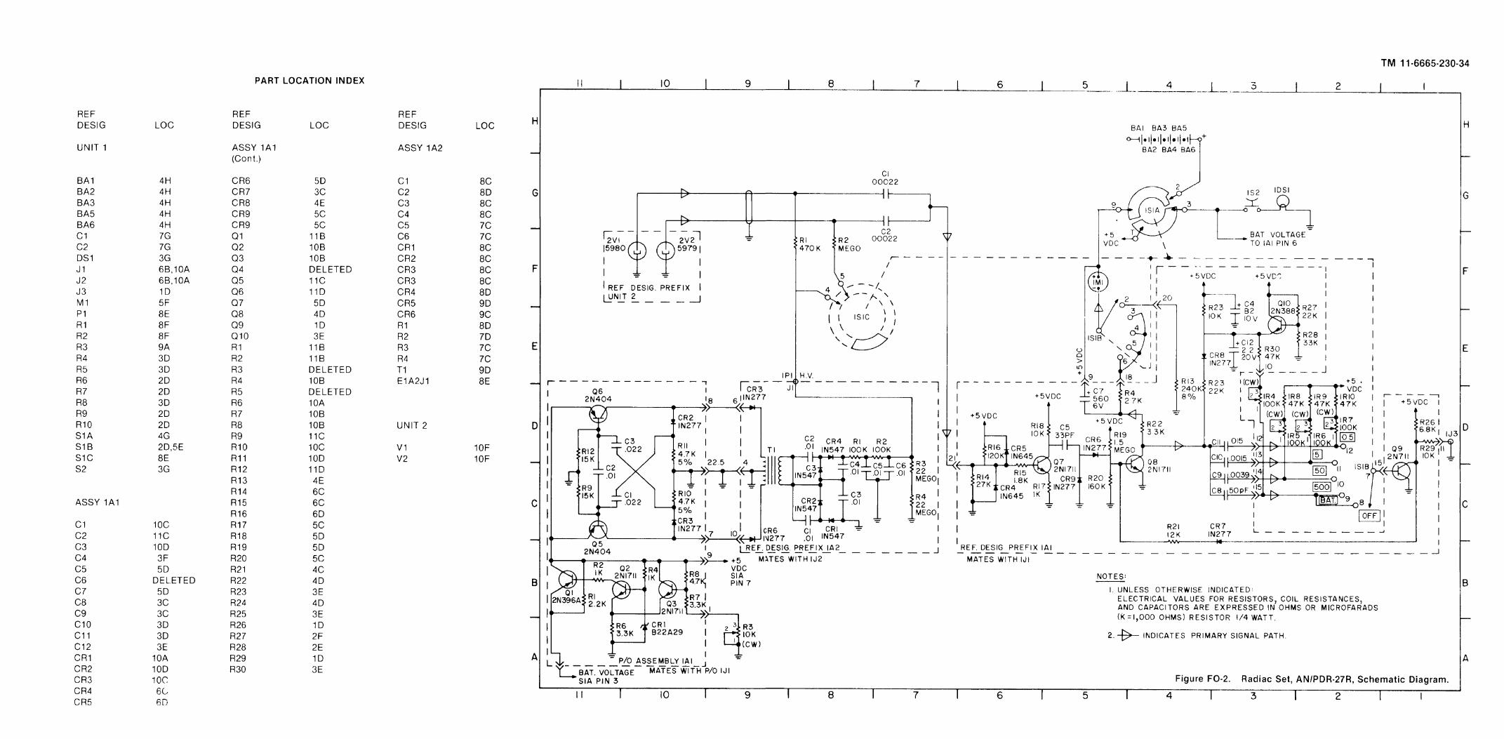
1-14. Reference Designations and Abbreviations● Unit and assembly numbers represent the radiac set’s assemblies.
Unit 1 - Radiacmeter PanelUnit 2 - Radiac Detector, DT-196/PDRAssembly 1A1 - Low Voltage PC BoardAssembly 1A2 - High Voltage PC BoardExample: Capacitor C1 of Assembly 1A1 is designated 1A1C1.
● Abbreviations of component parts complete the full reference designations.Example: Meter M1, on Unit 1 is designated 1M1.
1-2
TM 11-6665-230-34
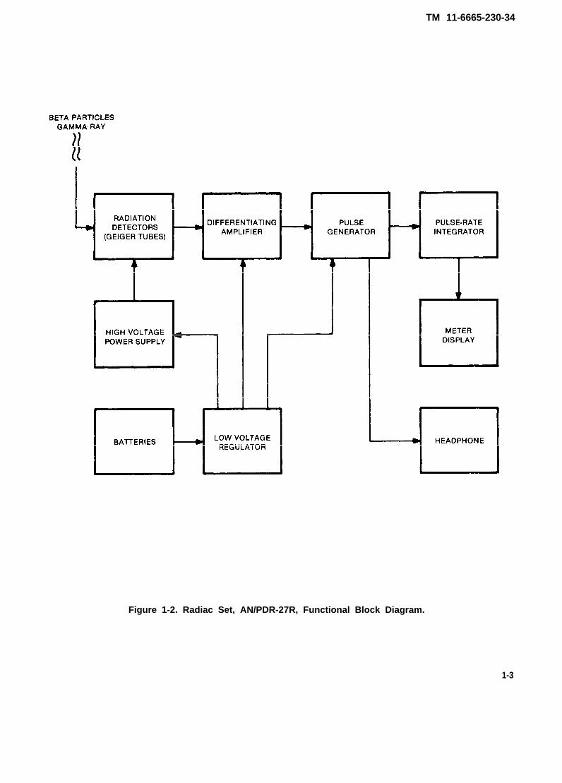
Figure 1-2. Radiac Set, AN/PDR-27R, Functional Block Diagram.
1-3
TM 11-6665-230-34
Section III. TECHNICAL PRINCIPLES OF OPERATION
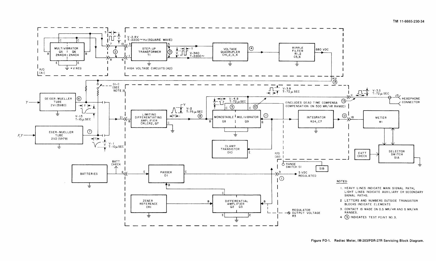
1-15. Functional Block Diagram(fig. 1-2)
The functional block diagram for Radiac Set, AN/PDR-27R is illustrated in figure 1-2. The high voltagepower supply furnishes a dc voltage to energize the Geiger-Mueller tubes. Beta particles (on the 0.5 andthe 5.0 mR/hr. ranges) and gamma rays cause the Geiger Mueller tubes to produce voltage pulses whichare then fed through a differentiating amplifier to a pulse generator followed by an integrator circuit. Thepulse generator provides pulses to the headphone for aural monitoring and supplies a direct current, pro-portional to the average pulse repetition frequency, to the indicating meter.
NOTE
Power for all functional blocks is obtained from dry cells through the voltageregulator. The regulator circuit assures that all operating voltages are main-tained constant throughout the useful life of the batteries (battery life is in ex-cess of 100 hours).
1-16. Functional Section Description(fig. FO-2)
a. Voltage Regulator. The battery voltage, which may vary from 9.3 to 6.6 volts dc during the useful lifeof the batteries, is fed to transistor 1A1Q1. The regulated voltage for the other circuitry in the equipmentis taken from the collector of 1A1Q1. This voltage is sampled by a differential amplifier composed of tran-sistors 1A1Q2 and 1A1Q3. The difference between the sample voltage and the fixed reference voltage isthen amplified and fed as negative feedback to the base of 1A1Q1. The output voltage of the regulator cir-cuit is then held constant over a wide range of input voltage variations. The value of the sample voltage isdetermined by the setting of potentiometer 1R3. The high voltage power supply develops a voltage pro-portional to the regulated low voltage, and 1R3 is used to adjust the high voltage to a precise value. Theregulated low voltage (about 5 volts dc) is adequate for operating the other circuitry.
b. High Voltage Power Supply.(1) The high voltage is developed by generating a square wave in an astable multivibrator, com-
posed of transistors 1A1Q5 and 1A1Q6 and feeding this square wave into a linear step-up transformer1A2T1. Oscillation is maintained in the astable multivibrator through a positive feedback loop from thecollector of transistor 1A1Q5 through diode 1A1CR3, and capacitor 1A1C3, to the base of transistor1A1Q6 and from the collector of 1A1Q6 through diode 1A1CR2, and through capacitor 1A1C1. Resistors1A1R10 and 1A1R11 are the resistive collector loads for transistors 1A1Q5 and 1A1Q6. When power isfirst applied, resistors 1A1R9 and 1A1R12 supply forward bias current to the bases of transistors 1A1Q5and 1A1Q6. However, due to slight unbalances in the circuitry associated with these two transistors,1A1Q5 draws slightly more current than 1A1Q6 and its collector swings positive, thus transmitting apositive voltage step to the base of 1A1Q6, cutting 1A1Q5 off. The coupling capacitor (1A1C1) or 1A1C3,whichever the case may be) then charges toward ground potential and when it reaches a potential ap-proximately 0.2 volts more negative than the emitters of transistors 1A1Q5 and 1A1Q6, the cut-off tran-sistor begins to conduct thus initiating a reversal of conduction state between the two transistors whichdevelops another such half-cycle and oscillation is sustained.
(2) The output of the multivibrator is applied through diodes 1A2CR5 and 1A2CR6 to theprimary of 1A2T1. These latter diodes in conjunction with diodes 1A1CR2 and 1A1CR3 insure that nofeedback path is established through the transformer back to transistors 1A1Q5 and 1A1Q6. Any suchpath would include two back-to-back series diodes, one which would of necessity be reverse biased, andthus effectively oppose any signal transfer along the path. Approximately 400 volts peak-to-peak, at thesecondary of 1A2T1 are then available to operate the voltage quadruple consisting of 1A2CR1 through1A2CR4 and the associated capacitors, 1A2C1 through 1A2C4. A ripple filter, consisting of resistors1A2R1, 1A2R2, and capacitors 1A2C5, and 1A2C6, reduces the ac component to a negligible value.Resistors 1A2R3 and 1A2R4 act as a bleeder on high voltage supply to discharge the filter capacitorswhen power is removed.
1-4
TM 11-6665-230-34
c. Radiation Detectors. The 680 V dc high voltage output supplies the two Geiger-Mueller tubes, 2V1and 2V2, through the range switch 1S1. The switching contacts of the range switch 1S1 are connected sothat Geiger-Mueller tube 2V1 is energized at all times (on all four ranges). Geiger-Mueller tube 2V2 is onlyin the circuit on the 0.5 mR/hr. and 5.0 mR/hr. ranges.
d. Computer-Integrator Circuitry.(1) When radiation causes either of the Geiger-Mueller tubes to discharge, a negative voltage
pulse is applied to the input of the differentiating amplifier 1A1Q7. Diodes 1A1CR4 and 1A1CR5 preventdamage to 1A1Q7 in the event of very high voltage pulses by shunting the excess current to ac ground.The output of transistor 1A1Q7 is taken from the collector and fed through a small capacitor 1A1C5 to themonostable multivibrator composed of transistors 1A1Q8, 1A1Q9 and their associated components. Thenormal state of the monostable multivibrator corresponds to full conduction (saturation) of transistor1A1Q9 since its base is returned to the 5 V dc supply through one of the following resistor networks,depending on the setting of the range switch, 1S1.
RANGE RESISTOR NETWORK
0.5 mR/hr. 1R7, 1R105.0 mR/hr. 1R6, 1R950 mR/hr. 1R5, 1R8500 mR/hr. 1R4, 1A1R30, 1A1R25
Transistor 1A1Q8 is normally turned off, since its base is returned to ground through resistor 1A1R20 andto the collector of transistor 1A1Q9 through resistor 1A1R21 and diode 1A1CR7. Since 1A1Q9 issaturated, as described above, the entire 5 V dc supply is dropped across its collector load resistor1A1R26. The collector sits at 0.2 volts above ground. The base of transistor 1A1Q8 is returned to poten-tials less than the 0.6 volt barrier potential necessary to initiate conduction keeping 1A1Q8 at cut off. Themeter 1M1 is in series with resistors 1A1R24 and 1A1R22, and form the collector load impedance of1A1Q8. The absense of current in the 1A1Q8 cusses the meter 1M1 to indicate zero in the normal state ofthe monostable multivibrator.
(2) When a positive going pulse arrives at the base of transistor 1A1Q8 from the collector of tran-sistor 1A1Q7, transistor 1A1Q8 begins to conduct. Therefore, a negative going step appears at the collec-tor of 1A1Q8, and this step is transferred through one of the coupling-timing capacitors, 1A1C8 through1A1C11, to the base of transistor 1A1Q9. This causes 1A1Q9 to come out of saturation, and a positive go-ing step thus appears at the collector of 1A1Q9. This latter positive going step is fed back to the base of1A1Q8 through diode 1A1CR7 and resistor 1A1R21. This positive going step reinforces the originalpositive pulse which initiated the process. This regenerative action continues until 1A1Q8 is completelysaturated and 1A1Q9 is completely cut off. At this point, since 1A1Q8 has gone from cutoff to full conduc-tion, it is evident that a negative going step equal in magnitude to the 5 volt supply voltage is generated.The base of 1A1Q9 sits at a potential approximately 4.4 volts negative with respect to ground. However,the base of 1A1Q9 is always returned to the positive 5 volt supply through a resistor network. Thisenables the coupling capacitors in the circuit (1A1C8 through 1A1C11) to begin to charge toward the 5 Vdc supply. After a time, determined by the value of the capacitor, by the total series resistance, and by thevoltage towards which the capacitor is changing, the base of 1A1Q9 reaches a potential about 0.6 voltsabove ground and 1A1Q9 begins to conduct. Now, the feedback causes a rapid return of the circuit to itsnormal state. The result of this action causes each received pulse from the Geiger-Mueller tubes 2V1 and2V2 to develop a fixed current to flowing into 1A1Q8’s collector load (including the meter 1M1) for a fixedperiod of time. This time is determined by the electrical characteristics of the components in the base cir-cuit of 1A1Q9. As long as the fixed conduction time interval is small compared to the average interval be-tween received pulses, the average current through 1M1 will be directly proportional to the average repeti-tion rate of the received pulses. Capacitor 1A1C7 smooths out the current pulses to the meter 1M1 so thatrapid fluctuations are suppressed.
(3) On the 500 mR/hr range, it should be noted that the monostable multivibrators couplingcapacitor 1A1C8 is returned to the positive supply voltage through resistors 1R4, 1A1R30, and 1A1R25. Ifthe multivibrator has remained in its normal or stable state for several seconds, it can be seen that cap-citor 1A1C12 will be charged to a positive voltage a few tenths of a volt below the supply voltage. If a
1-5

TM 11-6665-230-34
single pulse should now arrive from the Geiger-Mueller tube 2V1 the total charge which would passthrough meter 1M1 would be determined by the time that 1A1Q8 remained in the conducting state.
(4) At high pulse repetition rates, there is a greater probability of losing pulses because of thedead time of the system, so that we would like each pulse to have a somewhat greater effect in order tomaintain the system’s linearity. Therefore, the average voltage across 1A1C12 is reduced more and more as the pulse repetition rate increases because of the connection through 1A1CR8 and 1A1R23 to the col-lector of 1A1Q8, which drains charge from 1A1C12 during and only during the quasi-stable period ofoperation. This comprises the so-called Disc circuit to compensate for dead time.
(5) In order to prevent the circuit from locking up in the quasi-stable state, a clamp circuit com-posed of 1A1Q10, 1A1R27, and 1A1R28 is connected across 1A1C12. Thus, if the voltage across 1A1C12attempts to drop below approximately 2.4 V dc, 1A1Q10 begins to conduct strongly and maintains1A1C12 at that potential, providing forward bias for 1A1Q9 under any conditions.
(6) In addition, the pulse occurring at the collector of 1A1Q9 is fed to the BNC headphone con-nector 1J3 for aural monitoring of the detected pulses.
1-6
TM 11-6665-230-34
CHAPTER 2
GENERAL SUPPORT MAINTENANCE
Section 1. GENERAL INFORMATION
WARNING
Deathment.
2-1. General
on contact may result from contact with high voltage in this equip-The high voltage power supply produces 680 volts dc.
This chapter covers general support troubleshooting, maintenance, and test procedures for theradiacmeter.
WARNING
The test sample used in this equipment is radioactive. Damage to body tissuecan result from mishandling.
● Do not remove the test sample from the chain attaching it to the carrying case.● Do not handle the test sample by the radioactive end (purple end).● Do not prolong exposure to the radiation and handle the test sample unprotected.
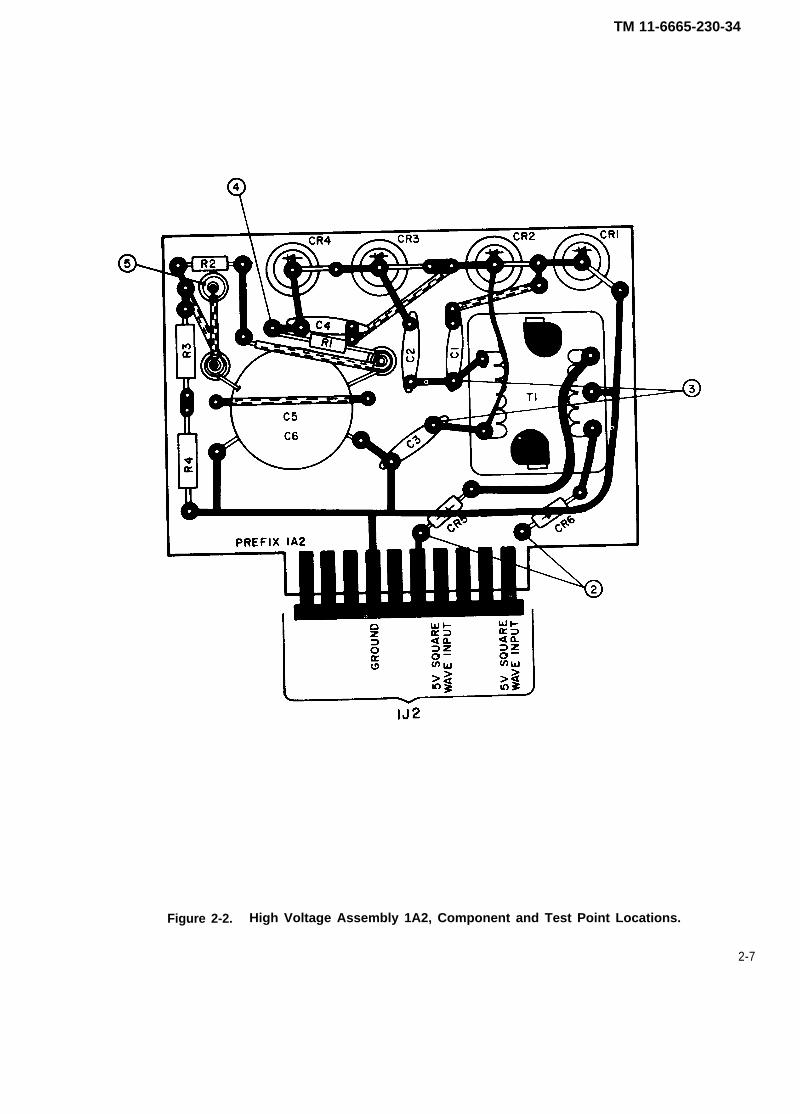
2-2. Maintenance Dataa. Normal waveform characteristics are shown in figure FO-1.b. Transistor voltages obtained with equipment in normal operating condition are shown in table 2-2.c. Use Radiac Calibrator Set AN/UDM-2 to calibrate the equipment.d. Replacement of parts on printed circuit boards (fig. 2-1 and fig. 2-2) will be performed only at an
authorized radiac repair facility.e. Parts location index and schematic diagram for this equipment are shown in figure FO-2.
NOTE
Replacement of any major component will require recalibration of this equip-ment.
2-3. Repair Parts, Tools, Test Equipment and Materials
in TMc.
listed
a .b .
Repair parts applicable to this equipment are listed in TM 11-6665-230-40P.Disassembly instructions and maintenance repair parts for Headset, Electrical H-43 B/U are shown11-5965-247-35P.Tools and test equipment required in the maintenance and troubleshooting of this equipment areas follows:
TOOLS
Nomenclature
Tool Kit, Electronic Equipment TK-105/G
National Stock Number
5180-00-610-8177
2-1
TM 11-6665-230-34
TEST EQUIPMENT
Radiac Calibrator Set AN/UDM-2 6665-00-179-9037Multimeter AN/PSM-45 6625-01-139-2512Oscilloscope AN/USM-488 TBDTest Set, Transistor TS-1836/U 6625-00-893-2628
d. No special tools are required for maintenance or repair of this equipment.
2-2
TM 11-6665-230-34
Section II. TROUBLESHOOTING
WARNING
Death on contact may result from contact with high voltage in this equip-ment. The high voltage power supply produces 680 volts dc.
2-4. General InformationTroubleshooting has three steps: sectionalization, localization, and isolation.
●✎ Sectionalization means tracing the fault to a module or assembly.● Localization means tracing the fault to a subassembly within a module or assembly.● Isolation means pin pointing the specific part or connection causing trouble.
2-5. Procedures
c.
toms,guide
a.b.
Check meter readings and other visual signs to sectionalize trouble.Check for dirt, dust, or moisture.Check for loose screws or nuts.(1) Operation. An operational test can help pinpoint trouble quickly (TM 11-6665-230-12).(2) Use of the troubleshooting table. The troubleshooting table, table 2-1, lists common symp-troubles, and corrective measures. Not all trouble symptoms are listed in the table, so use it as afor analyzing symptoms not listed.(3) Test point data. See figure 2-1, figure 2-2, and figure FO-1. Use with the troubleshooting chart
to isolate defective parts.(4) Removing and rep/acing parts. Refer to TM 11-6665-230-40P.
2-6. Symptom Recognitiona. This is the first step in the troubleshooting procedure and is based on a complete knowledge and
understanding of equipment operating characteristics. Not all equipment troubles are the direct result ofcomponent failure. Therefore, a trouble in an equipment is not always easy to recognize since all condi-tions of less than peak performance are not always apparent. This type of equipment trouble is usuallydiscovered while accomplishing preventive maintenance procedures, such as the preventivemaintenance checks and services shown in TM 11-6665-230-12.
b. After an equipment trouble has been recognized, all the available aids designed into theequipmemt should be used to further elaborate on the original trouble symptom. Also, checking or other-wise manipulating the operating controls may eliminate the trouble.
c. The next step in troubleshooting is to formulate a number of logical choices as to the causes andlikely location (functional section) of the trouble. The overall functional description (para 1-16) and itsassociated block diagram (fig. FO-1) should be referred to when selecting possible faulty functional sec-tions.
2-7. Troubleshootinga. The troubleshooting table lists the common malfunctions you may find during the maintenance of
Radiac Set AN/PDR-27R. You should perform the tests/inspections and corrective actions in the orderlisted.
b. Use the troubleshooting table to localize and isolate trouble. The table supplements the opera-tional checks, and PMCS tables in TM 11-6665-230-12. Also, the table is designed to be used with the testpoint data.
c. This manual cannot cover all the troubles that may occur, nor all tests or inspections and correc-tive actions. If a trouble is not listed or cannot be corrected by doing the corrective actions, notify yoursupervisor.
d. When using the troubleshooting table, the numbered statements represent the malfunction or par-ticular trouble to be remedied. The second indenture notes what test or inspection is to be performed inan attempt to isolate the trouble. The third indenture lists the corrective action to eliminate the trouble.
2-3
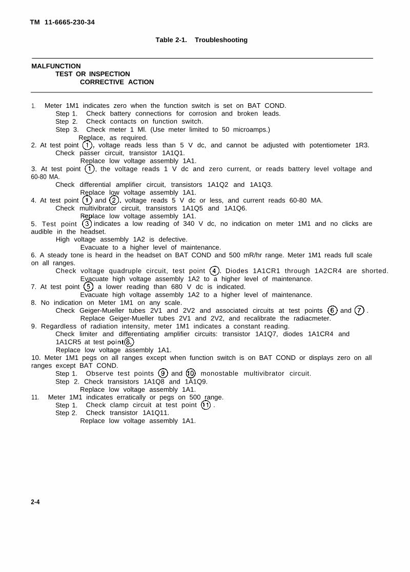
TM 11-6665-230-34
Table 2-1. Troubleshooting
MALFUNCTIONTEST OR INSPECTION
CORRECTIVE ACTION
1. Meter 1M1 indicates zero when the function switch is set on BAT COND.Step 1. Check battery connections for corrosion and broken leads.Step 2. Check contacts on function switch.Step 3. Check meter 1 Ml. (Use meter limited to 50 microamps.)
Replace, as required.2. At test point ~, voltage reads less than 5 V dc, and cannot be adjusted with potentiometer 1R3.
Check passer circuit, transistor 1A1Q1.Replace low voltage assembly 1A1.
3. At test point ~, the voltage reads 1 V dc and zero current, or reads battery level voltage and60-80 MA.
Check differential amplifier circuit, transistors 1A1Q2 and 1A1Q3.Replace low voltage assembly 1A1.
4. At test point @ and ~, voltage reads 5 V dc or less, and current reads 60-80 MA.Check multivibrator circuit, transistors 1A1Q5 and 1A1Q6.
Replace low voltage assembly 1A1.5. Test point 6 indicates a low reading of 340 V dc, no indication on meter 1M1 and no clicks areaudible in the headset.
High voltage assembly 1A2 is defective.Evacuate to a higher level of maintenance.
6. A steady tone is heard in the headset on BAT COND and 500 mR/hr range. Meter 1M1 reads full scaleon all ranges.
Check voltage quadruple circuit, test point @. Diodes 1A1CR1 through 1A2CR4 are shorted. Evacuate high voltage assembly 1A2 to a higher level of maintenance.
7. At test point @ a lower reading than 680 V dc is indicated.Evacuate high voltage assembly 1A2 to a higher level of maintenance.
8. No indication on Meter 1M1 on any scale.Check Geiger-Mueller tubes 2V1 and 2V2 and associated circuits at test points @ and @ .
Replace Geiger-Mueller tubes 2V1 and 2V2, and recalibrate the radiacmeter.9. Regardless of radiation intensity, meter 1M1 indicates a constant reading.
Check limiter and differentiating amplifier circuits: transistor 1A1Q7, diodes 1A1CR4 and1A1CR5 at test point@Replace low voltage assembly 1A1.
10. Meter 1M1 pegs on all ranges except when function switch is on BAT COND or displays zero on allranges except BAT COND.
Step 1. Observe test points @ and @ monostable multivibrator circuit.Step 2. Check transistors 1A1Q8 and 1A1Q9.
Replace low voltage assembly 1A1.11. Meter 1M1 indicates erratically or pegs on 500 range.
Step 1. Check clamp circuit at test point @ .Step 2. Check transistor 1A1Q11.
Replace low voltage assembly 1A1.
2-4
TM 11-6665-230-34
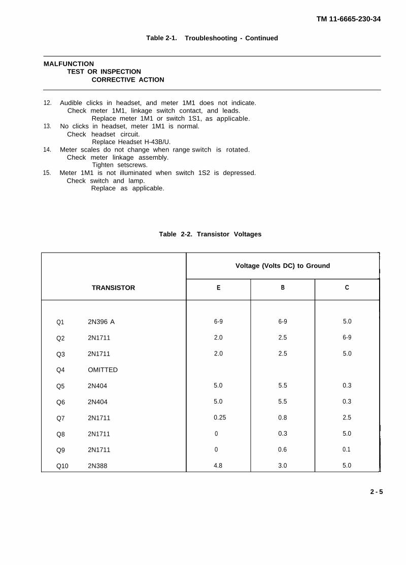
Table 2-1. Troubleshooting - Continued
MALFUNCTIONTEST OR INSPECTION
CORRECTIVE ACTION
12.
13.
14.
15.
Audible clicks in headset, and meter 1M1 does not indicate.Check meter 1M1, linkage switch contact, and leads.
Replace meter 1M1 or switch 1S1,No clicks in headset, meter 1M1 is normal.
Check headset circuit.Replace Headset H-43B/U.
Meter scales do not change when rangeCheck meter linkage assembly.
Tighten setscrews.
as applicable.
switch is rotated.
Meter 1M1 is not illuminated when switch 1S2 is depressed.Check switch and lamp.
Replace as applicable.
Table 2-2. Transistor Voltages
Voltage (Volts DC) to Ground
TRANSISTOR E B C
Q1 2N396 A 6-9 6-9 5.0
Q2 2N1711 2.0 2.5 6-9
Q3 2N1711 2.0 2.5 5.0
Q4 OMITTED
Q5 2N404 5.0 5.5 0.3
Q6 2N404 5.0 5.5 0.3
Q7 2N1711 0.25 0.8 2.5
Q8 2N1711 0 0.3 5.0
Q9 2N1711 0 0.6 0.1
Q10 2N388 4.8 3.0 5.0
2 - 5
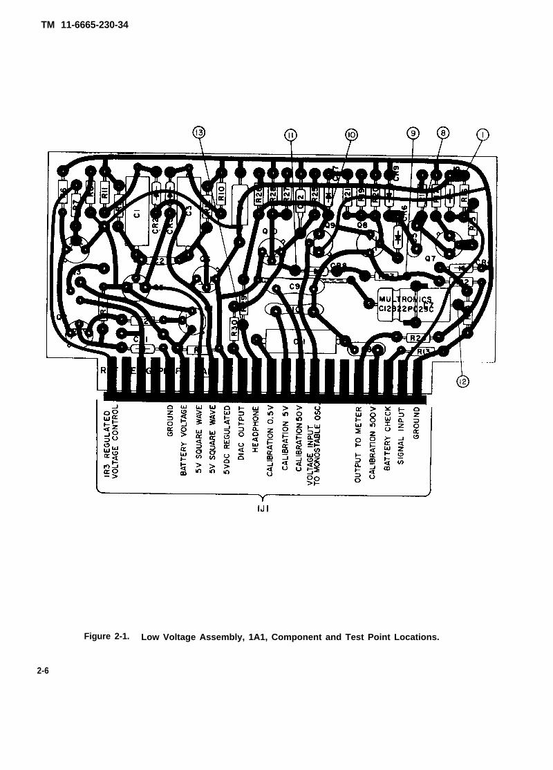
TM 11-6665-230-34
Figure 2-1. Low Voltage Assembly, 1A1, Component and Test Point Locations.
2-6
TM 11-6665-230-34
Figure 2-2. High Voltage Assembly 1A2, Component and Test Point Locations.
2-7
TM 11-6665-230-34
Section III. MAINTENANCE PROCEDURES
2-8. Operational CheckAn operational check of this equipment shall be performed in accordance with the PMCS chart (TM11-6665-230-12).
2-9. Removal and Replacing PartsRepair parts are listed and illustrated in the repair parts and special tools list (TM 11-6665-230-40P) coveringgeneral support maintenance for this equipment.
a. Radiac Detector DT-196/PDR-27. Removal and replacement of Geiger-Mueller tube 2V1.(1) Unscrew and remove gland nut (14) completely.(2) Remove electron tube holder (16) from electron tube housing (19).
CAUTION
Care should be taken not to bend the assembly or put strain on the electrontube holder.
NOTE
Replacement of Geiger-Mueller tubes 2V1 and 2V2 wil l require recalibration of
this equipment. However, even though the radiacmeter may be inaccurate with
respect to absolute intensity, i t wil l st i l l be useable to indicate relative intensity
within any one scale position. This means that it is possible to recognize in which
of two locations the intensity is higher, even though the actual intensit ies are in
error. i f readings are taken in the two locations on the same posit ion, the
reading correctly represents the higher intensity.
(3) Carefully remove Geiger-Mueller tube 2V1 (18) from the electron tube holder (16).(4) Insert the replacement tube on the electron tube holder (16).(5) insert the tube holder assembly (16) into the electron tube housing (19). Observe the precau-
tions of b below.(6) Replace and tighten the gland nut (14).
b. Removal and Replacement of Geiger-Mueller Tube 2V2,
CAUTION
The mica window is only .005 inches thick, and is
the window under any circumstances, as damage
extremely fragile. Do not touch
to the tube wil l result.
(1) Remove the brass cap (6) located at cable end of probe.
CAUTION
Do not twist cable (11) at any time.
(2) Remove the anode cap (23) of 2V2 with a pair of long-nose pliers.(3) Open the radiation shield (28) and remove the cover assembly (26).(4) Carefully remove the window guard (25), and care should be taken not to touch the mica win-
dow of 2V2.
2-8
TM 11-6665-230-34
(5) Gently push on the anode cap of tube 2V2 until the window projects enough to enablewithdrawal of 2V2 (22) from its housing (1).
(6) Replace the O ring at the neck of 2V2. Slide the O ring completely to the window end of thehousing (1).
(7) Push replacement tube 2V2 into the housing (19). Place the nut (24) and window guard (25)over the window to fully insert the tube.
(8) Insert the window guard (25) and large nut (24). Tighten securely.(9) Close the radiation shield (28).
c. Radiac Meter IM-203/PDR-27R, Removal and replacement of low voltage assembly 1A1, highvoltage assembly 1A2, and meter 1M1.
(1) Loosen the six screws located around the perimeter of the front panel of the radiacmeterhousing and remove the front panel.
(2) Remove the two plug-in printed wiring boards (low voltage assembly 1A1 and high voltageassembly 1A2).
CAUTION
The high voltage lead to the smaller board (1A2) disconnects at the board bya separate plug on the base of the board.
(3) Unsolder both leads to the meter and tag the lead that goes to the positive terminal on themeter.
(4) Loosen the setscrews on the meter range linkage at the meter and at the range switch andcarefully remove the linkage.
(5) Remove the four 6-32 x 9/16 inch meter mounting screws and associated washers. Thesescrews also secure the chassis to the front panel.
(6) Carefully lift the chassis away from the front panel and slide the meter toward the top of thefront panel.
(7) Carefully insert the new meter and position in place, making sure that the rubber gasket isproperly positioned over the front panel window, and that all leads are clear of the meter frame.
(8) Position the chassis over the meter and insert the four mounting screws, making sure that theground lug which was under the screw head nearest the calibration resistors is fastened. Tighten allmounting screws alternately in steps to maintain an even stress on the meter.
(9) Resolder meter leads, tagged lead to positive terminal.(10) Reposition the meter range linkage on the meter shaft and range switch. Tighten setscrews
on range switch shaft only.(11) Set the range switch to BAT COND position, grasp the meter shaft (with long nose pliers,
large tweezers, or similar tool) and rotate until the center mark of the batter scale is alined with the majordivision at midscale on the fixed scale of the meter. Carefully tighten the setscrews. Rotate the rangeswitch, and check to be sure that the correct meter scale appears clearly in view, for each switch posi-tion.
Section IV. GENERAL TEST REQUIREMENTS
NOTE
The tests outlined in this section are designed to measure the performancecapability of a repaired equipment. Equipment that is to be returned to theuser should meet the standards given in these tests.
2-10. Initial Preparationa. Perform all tests at normal room temperatures.b. Perform all modification word orders applicable to this equipment before making the tests
specified. DA PAM 310-1 lists all available MWO’S.
2-9
DANGER
TM 11-6665-230-34
c. The test equipment required to determine whether the radiac set complies with general supportmaintenance standards is located in section 1 of this chapter.
d.e.f.g.
2-11.a.b.c.
Before testing the equipment, allow 5 minutes for it to reach a stable temperature.Obtain six BA-30 Batteries and check them.Insert the batteries in the radiacmeter battery compartment.Separate the top panel from the radiacmeter bottom casting by removing the six panel screws.
Regulator Output TestSet radiacmeter range switch 1S1 to 50 and the multi meter RANGE switch to 10 V dc.Connect the multimeter between test point @ and ground.Adjust radiacmeter regulator output control 1R3 until + 5 ±0.1 volts is indicated on the
multimeter.d. Disconnect the multimeter from the radiacmeter.
WARNING
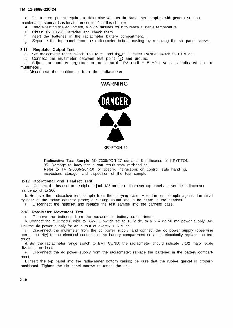
KRYPTON 85
Radioactive Test Sample MX-7338/PDR-27 contains 5 millicuries of KRYPTON85. Damage to body tissue can result from mishandling.Refer to TM 3-6665-264-10 for specific instructions on control, safe handling,inspection, storage, and disposition of the test sample.
2-12. Operational and Headset Testa. Connect the headset to headphone jack 1J3 on the radiacmeter top panel and set the radiacmeter
range switch to 500.b. Remove the radioactive test sample from the carrying case. Hold the test sample against the small
cylinder of the radiac detector probe; a clicking sound should be heard in the headset.c. Disconnect the headset and replace the test sample into the carrying case.
2-13. Rate-Meter Movement Testa. Remove the batteries from the radiacmeter battery compartment.b. Connect the multimeter, with its RANGE switch set to 10 V dc, to a 6 V dc 50 ma power supply. Ad-
just the dc power supply for an output of exactly + 6 V dc.c. Disconnect the multimeter from the dc power supply, and connect the dc power supply (observing
correct polarity) to the electrical contacts in the battery compartment so as to electrically replace the bat-teries.
d. Set the radiacmeter range switch to BAT COND; the radiacmeter should indicate 2-1/2 major scaledivisions, or less.
e. Disconnect the dc power supply from the radiacmeter; replace the batteries in the battery compart-ment.
f. Insert the top panel into the radiacmeter bottom casing; be sure that the rubber gasket is properlypositioned. Tighten the six panel screws to reseal the unit.
2-10
TM 11-6665-230-34
2-14. Checking Calibration
NOTE
Before checking calibration of the AN/PDR-27R, determine positions of the Xand Y axis bars, and the height control of the radiac calibrator set according toinstruction given in TM 11-6665-227-12. Calibration should be checked in accor-dance with operating instructions contained in the technical manual. Check thecalibration of each of the four ranges of the radiacmeter at four-fifths (0.4, 4, 40,and 400) of full-scale value with the radiac calibrator set. The meter indicationmust be four-fifths of full-scale value ± 20 percent on each range.
2-11/(2-12 blank)
TM 11-6665-230-34
APPENDIX A
REFERENCES
A-1. SCOPE.This appendix lists all forms, field manuals, technical manuals, and miscellaneous publications referenced in thismanual.
A-2. FORMS.Report of Discrepancy . . . . . . . . . . . . . . . . . . . . . . . . . . . . . . . . . . . . . . . . . . . . . . . . . . . . . . . .SF 364Quality Deficiency Report . . . . . . . . . . . . . . . . . . . . . . . . . . . . . . . . . . . . . . . . . . . . . . . . . . . . .SF 368Recommended Changes to Publications and Blank Forms. . . . . . . . . . . . . . . . . . . . . . . . .DA Form 2028/2028-2Discrepancy in Shipment Report . . . . . . . . . . . . . . . . . . . . . . . . . . . . . . . . . . . . . . . . . . . . . . .SF 361
A-3. TECHNICAL MANUALS.Operator’s Manual: Radioactive Test Sample, Krypton 85,
Gamma MX-7338/PDR-27R . . . . . . . . . . . . . . . . . . . . . . . . . . . . . . . . . . . . . . . . . . . . . . .TM 3-6665-264-10Administrative Storage Requirements . . . . . . . . . . . . . . . . . . . . . . . . . . . . . . . . . . . . . . . . . .TM 740-90-1Destruction of Army Electronics Material . . . . . . . . . . . . . . . . . . . . . . . . . . . . . . . . . . . . . . . .TM 750-244-2Field and Depot Maintenance Repair and Special Tools List;
Headset, Electrical H-43B/U . . . . . . . . . . . . . . . . . . . . . . . . . . . . . . . . . . . . . . . . . . . . .TM 11-5965-247-35POperator’s and Organizational Maintenance Manual:
Calibrator Set Radiac, AN/UDM-2 (NSN 6665-00-179-9037) . . . . . . . . . . . . . . . . . . . .TM 11-6665-227-12Hand Receipt . . . . . . . . . . . . . . . . . . . . . . . . . . . . . . . . . . . . . . . . . . . . . . . . . . . . . . . . . . . . . . . ..TM 11-6665-230-12-HROperator’s and Organizational Maintenance Manual:
Radiac Set AN/PDR-27R (NSN 6665-00-961-0846) . . . . . . . . . . . . . . . . . . . . . . . . . . . . .TM 11-6665-230-12Organizational Maintenance Repair Parts and Special
Tools List for Radiac Set AN/PDR-27R(NSN 6665-00-961 -0846 ) . . . . . . . . . . . . . . . . . . . . . . . . . . . . . . . . . . . . . . . . . . . . . . . . TM 11-6665-230-20P
General Support Maintenance Repair Parts andSpecial Tools List (Including Depot MaintenanceRepair Parts and Special Tools) for Radiac SetAN/PDR-27R (NSN 6665-00-961-0846) . . . . . . . . . . . . . . . . . . . . . . . . . . . . . . . . . . . . . .TM 11-6665-230-40P
A-4. MISCELLANEOUS PUBLICATIONS.Consolidated lndex of Army Publications and Blank Forms . . . . . . . . . . . . . . . . . . . . . . . .DA Pam 310-1The Army Maintenance Management System . . . . . . . . . . . . . . . . . . . . . . . . . . . . . . . . . . . .DA Pam 738-750
A-1/(A-2 blank)
TM 11-6665-230-34
APPENDIX E
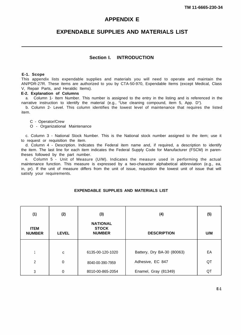
EXPENDABLE SUPPLIES AND MATERIALS LIST
Section I. INTRODUCTION
E-1. ScopeThis appendix lists expendable supplies and materials you will need to operate and maintain theAN/PDR-27R. These items are authorized to you by CTA-50-970, Expendable Items (except Medical, ClassV, Repair Parts, and Heraldic Items).E-2. Explanation of Columns
a. Column 1- Itern Number. This number is assigned to the entry in the listing and is referenced in thenarrative instruction to identify the material (e.g., “Use cleaning compound, item 5, App. D“).
b. Column 2- Level. This column identifies the lowest level of maintenance that requires the listeditem.
C - Operator/CrewO - Organizational Maintenance
c. Column 3 - National Stock Number. This is the National stock number assigned to the item; use itto request or requisition the item.
d. Column 4 - Description. Indicates the Federal item name and, if required, a description to identifythe item. The last line for each item indicates the Federal Supply Code for Manufacturer (FSCM) in paren-theses followed by the part number.
e. Column 5 - Unit of Measure (U/M). Indicates the measure used in performing the actualmaintenance function. This measure is expressed by a two-character alphabetical abbreviation (e.g., ea,in, pr). If the unit of measure differs from the unit of issue, requisition the lowest unit of issue that willsatisfy your requirements.
EXPENDABLE SUPPLIES AND MATERIALS LIST
(1) (2) (3) (4) (5)
NATIONALITEM STOCK
NUMBER LEVEL NUMBER DESCRIPTION U/M
1 c 6135-00-120-1020 Battery, Dry BA-30 (80063) EA
2 0 8040-00-390-7959 Adhesive, EC 847 QT
3 0 8010-00-865-2054 Enamel, Gray (81349) QT
E-1
TM 11-6665-230-34
INTENSITY
GLOSSARY
DEFINITION OF UNUSUAL TERMS
The energy (of any radiation) incident upon (or following through) unit area,perpendicular to the radiation beam, in unit time. As applied to nuclear radia-tion, the term intensity is sometimes used to express the exposure dose rateat a given location in roentgens or milliroentgens per hour.
MILLIROENTGENS One-thousandth of a roentgen (abbreviation mR/hr).
RADIOACTIVITY The spontaneous emission of radiation, generally alpha or beta radiation,often accompanied by gamma radiation from the nuclei of an unstable ele-ment.
ROENTGEN The international unit of x-radiation or gamma radiation equal to the amountof radiation that produces in one cubic centimeter of dry air at 0°C and stan-dard atmospheric pressure ionization of either sign equal to one electrostaticunit of charge (also see milliroentgen).
SHIELDING Is the act of reducing or preventing passage of particles or radiation.
FOLDOUT INDEX
Figure FO-1.
Figure FO-2.
Radiac Meter, lM-203/PDR-27R, Servicing Block Diagram
Radiac Set, AN/PDR-27R, Schematic Diagram
E-2
TM 11-6665-230-34
Figure FO-1. Radiac Meter, IM-203/PDR-27R Servicing Block Diagram.
TM 11-6665-230-34
Figure FO-2. Radiac Set, AN/PDR-27R, Schematic Diagram.
By Order of the Secretary of the Army:
Official:
JOHN A. WICKHAM JR.General, United States Army
Chief of Staff
ROBERT M. JOYCEMajor General, United States Army
The Adjutant General
DISTRIBUTION:
To be distr ibuted in accordance with DA Form 12-50 requirementsfor AN/PDR-27R.
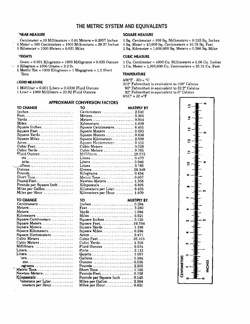
THE METRIC SYSTEM AND EQUIVALENTS

PIN: 056644-000