Embed Size (px)
Citation preview
TM 5-304
TECHNICALMANUAL
ARMY FACILITIES COMPONENTS SYSTEM USER GUIDE
APPROVED FOR PUBLIC RELEASE; DISTRIBUTION IS UNLIMITED
HEADQUARTERS, DEPARTMENT OF THE ARMY OCTOBER1990
REPRODUCTION AUTHORIZATION/RESTRICTIONS
This manual has been prepared by or for the Government and is public property and not subject to copyright.
Reprints or republications of this manual should include a credit substantially as follows: “Department of the Army, USA, TM 5-304, Army Facilities Components System User Guide.”

TECHNICAL MANUAL No. 5-304
* TM S-304
HEADQUARTERS DEPARTMENT OF THE ARMY
WASHINGTON, D.C., 1 October 1990
ARMY FACILITIES COMPONENTS SYSTEM USER GUIDE
Paragraph Page
CHAPTER 1
CHAPTER 2
INTRODUCTION
Purpose .................................. l-l
Scope ................................... l-2
References ................................ l-3
Explanation of Abbreviations ..................... l-4
Background ............................... l-5
AFCS Publications ........................... l-6
Comments and Information Sources ................. l-7
Inconsistencies, Errors, and Omissions ................ 1-S
Responsibilities ............................. 1-9
Camouflage and Dispersal ....................... l-10
Bomb Damage Repair ......................... l-11
AFCS TERMINOLOGY AND DATA
AFCS ................................... 2-l
Building Blocks ............................. 2-2
Planning Table ............................. 2-3
Design Criteria .............................. 2-4
Construction Standards and Procurement Considerations ..... 2-5
Types of Structures ........................... 2-6
Material Waste and Loss ........................ 2-7
Climatic Zones .............................. 2-S
Construction Effort ........................... 2-9
Engineer Unit Capabilities ....................... 2-10
Logistical and Cost Information .................... 2-11
Operational Conditions ......................... 2-12
Storage and Transit Conditions .................... 2-13
l-l
l-l
l-l
l-l
l-l
l-l
l-2
l-2
l-3
l-3
l-3
2-l
2-l
2-l
2-l
2-2
2-2
2-2
2-2
2-2
2-4
2-4
2-4
2-5
APPROVED FOR PUBLIC RELEASE; DISTRIBUTION IS UNLIMITED
*This manual supersedes TM 5-304, October 1979
TM 5-304
CHAFTER 3
CHAPTER 4
CHAF’TER 5
APPENDIX A
AF’PENDIX B
APPENDIX C
Paragraph
Site Orientation ............................. .2-14
Facilities for Initial Period (Up To 6 Months) ............ .2-15
Facilities for a Temporary Period (Greater Than 6 Months) .... .2-16
OVERVIEW OF TM 5-301, TM 5-302, TM 5-303, AND THE TACAPS USER GUIDE
General .................................. 3-l
Use of TM 5-301 ............................. 3-2
Use of TM 5-302 ............................. 3-3
UseofTM5-303 ............................ .3-4
TACAPS User Guide .......................... 3-5
EXAMPLE PROBLEMS
General .................................. 4-l
Multiple Choice Problems (Table Consultation) ........... .4-2
Simplified Lead-through Problems .................. 4-3
UsingAFCSinPlanningandDesign ................. .4-4
REQUISITION AND SUPPLY
Construction Supplies .......................... S-1
Requisitioning Procedures ....................... S-2
Methods of Shipment .......................... .5-3
Foreign Procurement .......................... .5-4
Materials Management ......................... .5-5
Functional Flowchart .......................... S-6
REFERENCES
Army Regulations ............................ A-l
Army Supply Catalog .......................... .A-2
Field Manuals .............................. A-3
Technical Manuals ........................... .A-4
Huntsvihe Division Manual ....................... A-5
CAMOUFLAGE AND DISPERSAL
Defensive Measures .......................... B-l
Camouflage ............................... .B-2
Dispersal ................................. B-3
BOMB DAMAGE REPAIR MATRIX ...................
Page
2-5
2-5
2-6
3-l
3-l
3-2
3-3
3-3
4-l
4-l
4-2
4-6
5-l
5-l
5-2
5-2
5-2
5-2
A-l
A-l
A-l
A-l
A-l
B-l
B-l
B-2
C-l
ii
TM 5-304
APPENDIX D CLIMATIC CONDITIONS
APPENDIX E
APPENDIX F
APPENDIXG
GLOSSARY
Figure Title Page
2-l Building orientation .................................. 2-6
3-l Example of an installation planning table ..................... .3-2
3-2 Exampleofafacilityplanningtable ........................ .3-3
3-3 Typical TM 5-303 entry ............................... .34
3-4 ExampleofaTOE .................................. .3-4
4-l Procedure for solving lead-through problems .................... 4-3
4-2 Components of a 20-by-60-foot building ....................... 4-6
4-3 AFCS planning and design procedure flow ..................... 4-7
44 Calculations for project duration ........................... 4-11
5-l Requisition and supply process ............................ 5-3
B-l Dispersal heliport layout ............................... B-Q
B-2 Heliport layout, friendly air superiority ....................... B-5
B-3 Layout, all types of aircraft .............................. B-6
B-4 Fixed-wing aircraft layout ............................... B-7
Paragraph Page
Explanation of Climatic Terms . . . . . . . . . . . . . . . . . . . . . D-l
Temperate Zone: Intermediate Hot-dry and Intermediate Cold . . D-2
Tropical Zone: Wet-Warm and Wet-Hot . . . . . . . . . . . . . . . D-3
Frigid Zone: Cold . . . . . . . . . . . . . . . . . . . . . . . . . . . . D-4
Desert Zone: Humid-Hot Coastal Desert and Hot-dry . . . . . . . D-5
ENGINEERING CAPABILITY TABLES . . . . . . . . . . . . . . . . .
CONSTRUCTION DRAWINGS
D-l
D-l
. . .
D-5
D-5
E-l
Purpose . . . . . . . . . . . . . . . . . . . . . . . . . . . . . . . . . . F-l
Types of Drawings. . . . . . . . . . . . . . . . . . . . . . . . . . . . F-2
Symbols on Drawings . . . . . . . . . . . . . . . . . . . . . . . . . . F-3
CPM NETWORK
Using CPM . . . . . . . . . . . . . . . . . . . . . . . . . . . . . . . G-l
CPM Symbols . . . . . . . . . . . . . . . . . . . . . . . . . . . . . . G-2
CPM Example . . . . . . . . . . . . . . . . . . . . . . . . . . . . . . G-3
F-l
F-l
F-6
G-l
G-l
G-3
........................................... Glossary-l
LIST OF FIGURES
. . . III
TM 5-304
Figure
F-l
F-2
F-3
F-4
F-5
F-6
F-7
F-S
F-9
F-10
G-l
G-2
G-3
G4
G-5
G-6
Table
2-1
2-2
2-3
4-l
4-2
4-3
D-l
E-l
E-2
E-3
EA
E-5
Tirle Page
Typical site plan .................................... F-2
Typical electrical plan ................................. F-3
Elevation views ..................................... F-4
Isometric views ..................................... F-5
Typical floor plan ................................... F-7
Sectional drawings ................................... F-8
Details ....................................... ..F- 9
Light framing details ................................. F-10
Typical wall panels-framing details ......................... F-11
Typical foundation and footing details ....................... F-12
Event numbers ..................................... G-l
Circular logic error .................................. G-l
CPM network ..................................... G-l
Example CPM diagram ................................ G-2
“Dummy” activity ................................... G-2
CPM diagram for a typical office building ..................... G-4
LIST OF TABLES
Title Page
Extra materials included for waste and loss ..................... 2-3
Ranges for operational conditions .......................... 2-4
Storage and transit conditions ............................ 2-5
Tabulations for example problem 5 ......................... 4-4
Tabulations for example problem 7 ......................... 4-5
Data for various construction components ..................... 4-10
Summary of temperature, solar radiation, and relative humidity extremes ... D-2
Equipment assumptions, engineer battalion (combat heavy) ........... E-l
Engineer unit capability table, engineer battalion (combat heavy) 5-4152, .... E-2
Engineer unit capability table, headquarters and support company engineer battalion (combat heavy) 5-416L .................... E-3
Engineer unit capability table, headquarters and support company engineer battalion (combat heavy) 5-41. .................... E-4
Engineer unit capability table, engineer company pipline construction 5-434L ............................. E-5
iv
TM 5-304
Table
E-6
E-7
E-8
G-l
G-2
Title Page
Engineer unit capability table, engineer company port construction 5-603L . . E-6
Engineer unit capability table, engineer company dump truck 5-424L . . . . . . E-7
Engineer unit capability table, engineer company construction support 5-4131, . . . . . . . . . . . . . . . . . . . . . . . . . . . . E-8
Construction activities for CPM example . . . . . . . . . . . . . . . . . . . . . . G-3
Tabulation of construction activities . _ _ . . . . . . . . . . . . . . . . . . . . . . G-5
v/vi
TM 5-304
CHAPTER 1
INTRODUCTION
1-I. PURPOSE
The purpose of this manual is to help personnel use the Army Facilities Components System (AFCS) and its products when preparing for and executing Army con- struction missions in a theater of operations (TO).
1-2. SCOPE
This manual is a single-source reference for the opera- tion of AFCS and available AFCS products. Example problems demonstrating the system’s use and informa- tion about requisition and supply procedures are in- cluded.
1-3. REFERENCES
Appendix A lists the references cited in this document.
I-4. EXPLANATION OF ABBREVIATIONS
Abbreviations and acronyms used in this manual are ex- plained in section I of the glossary. Abbreviations for construction materials are explained in section II of the glossary.
I-5. BACKGROUND
a. Definition. AFCS is a military engineering construc- tion support system for construction requirements in a TO. AFCS provides data to military planners so that they can prepare contingency plans and support estimates and specific design and logistics information for supply- ing, constructing, and maintaining facilities in a TO.
b. 17re NeedforAFCS. AFCS was designed in response to the vital need for an improved construction planning and supply system. Large inventory errors dis- covered at the close of World War II were basically caused by the supply system’s inadequate inventory capability. During the Korean Conflict, in the absence of a construction planning and supply system, TO planners lacked the resources needed to generate specific projects for base development. Thus, they were forced to use the World War II system of forecasting their needs for across-the-board items of construction material, primari- ly by reviewing the thousands of items in supply catalogs.
c. The Development of AFCS. Since its inception in 1951, AFCS has grown to include plamring guidance, detailed construction drawings, and computer updated bills of materials (BOM) for about 3,000 facilities. Some of the facilities included in the system are troop housing, hospitals, bridges, roads, supports, petroleum storage and distribution, and ammunition storage. The system is used:
l For joint, deliberate planning activities (Civil En- gineer Support Planning (CESP) development).
l By major Army commands (MACOM’s) for theater contingency planning, temporary construction projects, and engineer unit training.
l To support engineer contingency studies.
l To support operational projects.
l To determine contingency Class IV requirements.
l By the U.S. Army Training and Doctrine Command (TRADOC) to support individual training.
l To support Army force development processes.
d. l7ze Automation of AFCS. The Theater Army Con- struction Automated Planning System (TACAPS) was developed in 1985 in order to provide a method for ac- cessing and using current AFCS design and logistics master files in a remote location. TACAPS requires the user to have a microcomputer system for accessing and using AFCS logistics information. TACAPS provides an automated method of identifying, maintaining, and dis- seminating information for construction planning in a TO or for contingency situations. TACAPS has the uni- que capability of generating theater facility requirements in terms of either specific AFCS facilities or gross meas- urement requirements (such as square feet, gallons, etc.) for deployable Army units based on either unit type codes (UTC’s) or standard requirement codes (SCR’s).
I-6. AFCS PUBLICATIONS
AFCS consists of a series of four Department of the Army (DA) technical manuals (TM’s). TM 5-304 and its companion manuals, TM 5-301, TM 5-302, and TM 5- 303, and the TACAPS User Guide are described briefly
l-l
TM 5-304
in paragraphs a through d below. Chapter 3 provides detailed instructions for using the manuals.
a. TM 5-301 Series, Army Facilities Components Sys- tem -Planning. The 301 series is generally used by military planners and contains installation, facility, and prepackaged expendable contingency supplies (PECS) summaries. TM 5-301 is published in four volumes: TM 5-301-1, TM 5-301-2, TM 5-301-3, and TM 5-301-4. Each volume addresses a separate climatic zone: temperate, tropical, frigid, and desert, respectively. PECS sum- maries and facility listings include (1) cost, shipping weight, and volume of material and (2) estimated man- hours needed to construct each facility and installation. The TM 5-301 series may be used by planners at higher levels without referring to TM 5-302 and TM 5-303 (see b and c below). The U.S. Atmy Engineer Division, Huntsville (USAEDH) maintains current summary infor- mation for the facilities and installations listed in the TM 5-301 manuals.
b. TM 5-302 Series, Army Facilities Components Sys- tem -Design. The 302 series is a multivolume manual con- taining design drawings for installations and facilities; it is of primary interest to the unit actually constructing AFCS facilities in a TO. TM 5-302 is updated when new facilities are added to the system, old ones are deleted, or revisions are made. The designs address the four climatic zones listed in paragraph a above and the two construction standards described in paragraph 2-5 below. The manuals are printed and initially distributed through the U.S. Army Publications and Printing Com- mand.
c. TM 5-303 Series, Army Facilities Components Sys- tem -Logistics Data and BOM. The 303 series is general- ly used by planners, builders, and supply personnel who need to identify items in the BOM. Each item in a facility (or PECS kit) is identified by a National Stock Number (NSN) and an abbreviated description. The material cost, shipping weight, volume, and estimated construc- tion effort in man-hours are also provided. USAEDH maintains current logistics information for the items in TM 5-303; the information is available in TM 5-303 for- mat.
d. CEHND 1105-l-1, TAWS User Guide. Provided upon request, the TACAPS User Guide is an AFCS specialty document that is not one of the official AFCS TM’s; however, it does contain instructions for accessing and using the computerized facility and installation
l-2
master files of AFCS information. Chapter 3 provides further information about TACAPS.
I-7. COMMENTS AND INFORMiTlON SOURCES
Data for the manuals are maintained by the U.S. Army Corps of Engineers (USACE). The data in TM 5-301 and TM 5-303 are available by direct computer access via printouts, magnetic tape, or diskette. The drawings in TM 5-302 are half-size (14 by 20 inches) reproducible drawings; those drawings are also available, upon re- quest, in full-size (28 by 40 inches) reproducible or blueline prints or computer input diskette for computer- aided drafting and design. All correspondence and re- quests for technical assistance, drawings, and information regarding the AFCS system should be sent to either:
U.S. Army Engineer Division, Huntsville ATTN: CEHND-ED-SY P.O. Box 1600 Huntsville, AL 35807-4301
or
HQDA (DAEN-ZCM) Washington, DC 20310-2600
AFCS users are encouraged to submit comments and recommendations for improvement or revision directly to HQDA (DAEN-ZCM), Washington, DC. Comments should refer to the specific drawing, facility, or installa- tion. The reason for each comment or recommendation should be stated in order to ensure proper under- standing and evaluation.
I-8. INCONSISTENCIES, ERRORS, AND OMISSIONS
a. Design Reviews and Updates. AFCS is reviewed in order to isolate and correct inconsistencies and incor- porate changes in the design drawings and the BOM. Since design work has been carried out over a long period of time, updating and revising are continual.
b. Facility and Installation Suitability. Users should carefully study the facilities or installations they propose to acquire, since some facilities or installations might be complete as ordered, while others could require addition- al or fewer facilities in order to obtain the desired final product.
TM S-304
c. Cost Data Updates. Cost data are accurate only at the time of issue. Those data are updated quarterly and can be obtained from USAEDH or accessed by micro- computer in accordance with TACAF’S procedures.
I-9. RESPONSIBILITIES USACE continually reviews and updates this manual - a process that includes coordination with DA staff agen- cies, overseas commands, and other users affected by construction for contingency operations. AR 415-16 details the responsibilities of USACE and other agencies or commands.
l-10. CAMOUFLAGE AND DISPERSAL
a. Camouflage. Camouflage is the technique of con- cealing or disguising military activities, materiel, and per- sonnel. It is used to gain the element of surprise and to reduce destruction of equipment and personnel casual- ties by enemy actions. Camouflage permits the move-
ment and placement of materiel and personnel without detection and gives the impression of being in a position or location that is not really occupied.
b. Dispersal. AFCS installation plans use minimum real estate and utilities and are based on functional relationships between facilities. Where dispersal is re- quired because of terrain features or expected enemy ac- tions, additional roads, utilities, and real estate must be added to the plans and constructed.
c. Further Information. See appendix B for specific in- formation about using camouflage and dispersal.
I-l 1. BOMB DAMAGE REPAIR
Regardless of how secure a camp may be, the possibility that all or part of a facility could be damaged by enemy actions must be considered. See appendix C for a bomb damage repair matrix of suggestions about repairing typi- cal bomb damages.
l-314
TM !J-304
CHAFlER2
AFCS TERMINOLOGY AND DATA
2-I. AFCS AFCS is a system that helps all levels of military plan- ners, supply agency personnel, and construction person- nel who have a role in providing temporary Army facilities in support of contingencies.
2-2. BUILDING BLOCKS
AFCS uses a building block concept for maximum flexibility. Items, facilities, subfacilities, installations, and components, explained in paragraph a through e below, make up the building block system:
a. Item. An item is any construction material or equipment used to make up a facility. Each item has an associated NSN, description, unit of issue, and quantity. The following are examples of items:
l 5510-00-W-3964 Lumber Softwood Dim 2 Corn 2x4~12 BF (Qty)
l 53l5-00-W-5126 Nail Common 3d LB (Qty)
l 5530-00-262-8182 Plywood AI3 Ext 5 Ply 3/4x4&% in SH (Qty)
Tabulations of AFCS items required for each facility can be found in TM 5-303.
b. Facility. A facility is a group of items that provides a service. A facility can also be an item of equipment that enhances a function by providing specific physical assistance. Each facility is assigned and identified by a unique number. The following is an example of a facility description listed in TM 5-301-l:
14185AA Company Headquarters Building, 600 SF, wood construction, w/concrete floor, temperate climate
Each facility has an associated facility number, descrip- tion, unit of issue, shipping volume, shipping weight, and cost. Several facility numbers may be required to com- plete a functional facility. For example, constructing a finished and usable barracks building might require:
(1) The basic building.
(2) Additional bay (to extend building to some desired length).
(3) An insulation package.
(4) Electrical lighting and distribution package.
Users, therefore, should carefully read the facility description in TM 5-301 or TM 5-303 so that all neces- sary components are acquired.
c. SubfaClity. A subfacility differs from a facility only in its use in TM 5-303 (BOM). A subfacility reduces the repetitive listing of a facility? construction materials. When a facility is used as a subfacility, the entire subfacility is treated as one item of the major facility listed in the BOM. The subfacility’s name and a short description of it will appear in lieu of the NSN and shipping/logistics data for each of its items. The subfacility’s entire BOM will appear only where it is initially listed as a facility.
d Installation. An installation is a group of facilities designed to provide a specific service or support to a military function in a TO. Installations are listed in the Installation Planning Tables of TM 5-301 and in volume one of TM 5-302. Each installation has a unique associated number (two alpha and four numeric characters). For example:
l NT1131 Troop Camp, 250-man, temperate climate, temporary standard
l DA1061 Ammo Storage, 12,000-ton capacity for temperate climate
The shipping volume, shipping weight, cost, and labor re- quirements for each installation are also provided.
e. Component. Component is a generic term sometimes used to refer to any facility or installation in AFCS. It generally refers to one or more of the system’s building blocks.
2-3. PLANNING TABLE
A planning table is a tabulation of installation and facility logistical, cost, and engineering construction data from TM 5-301.
2-4. DESIGN CRITERIA
a. SiteAdaptation. Design assumptions and criteria, sometimes considered helpful for adapting a structure to specific site conditions, are shown in the working drawings of TM 5-302. Included is information such as maximum
2-l
TM 5-304
stresses of structural members, assumed concrete strength, minimum soil-bearing capacities, and thermal (climatic) operating range. Those data can be used by qualified personnel to modify the proposed facility if materials or conditions differ from what is listed in the manual.
b. Sa$ety. Because of the short design life of the facilities, the minimum safety factors for ensuring personnel and equipment safety during the mission are used. Therefore, AFCS standard designs do not necessarily meet building codes.
2-5. CONSTRUCTION STANDARDS AND PROCUREMENT CONSIDERATIONS
Construction standards are based primarily on the length of the contingency operation and are set by the theater commander. The following construction standards con- form to Joint Chief of Staff requirements and are in- cluded in the facility/installation descriptions printed in TM 5-301:
l Initial (INT) - up to 6 months.
l Temporary (TPR) - up to 24 months.
2-6. TYPES OF STRUCTURES
AFCS has two basic types of buildings: disposable and relocatable. Selection is based on mission requirements and resource availability.
a. Disposable. Wood frame, block, concrete, or any other material formed at the site and having little or no salvage value.
b. Relocatable. Pre-engineered, panelized buildings, or any other structure having S5-percent recoverability.
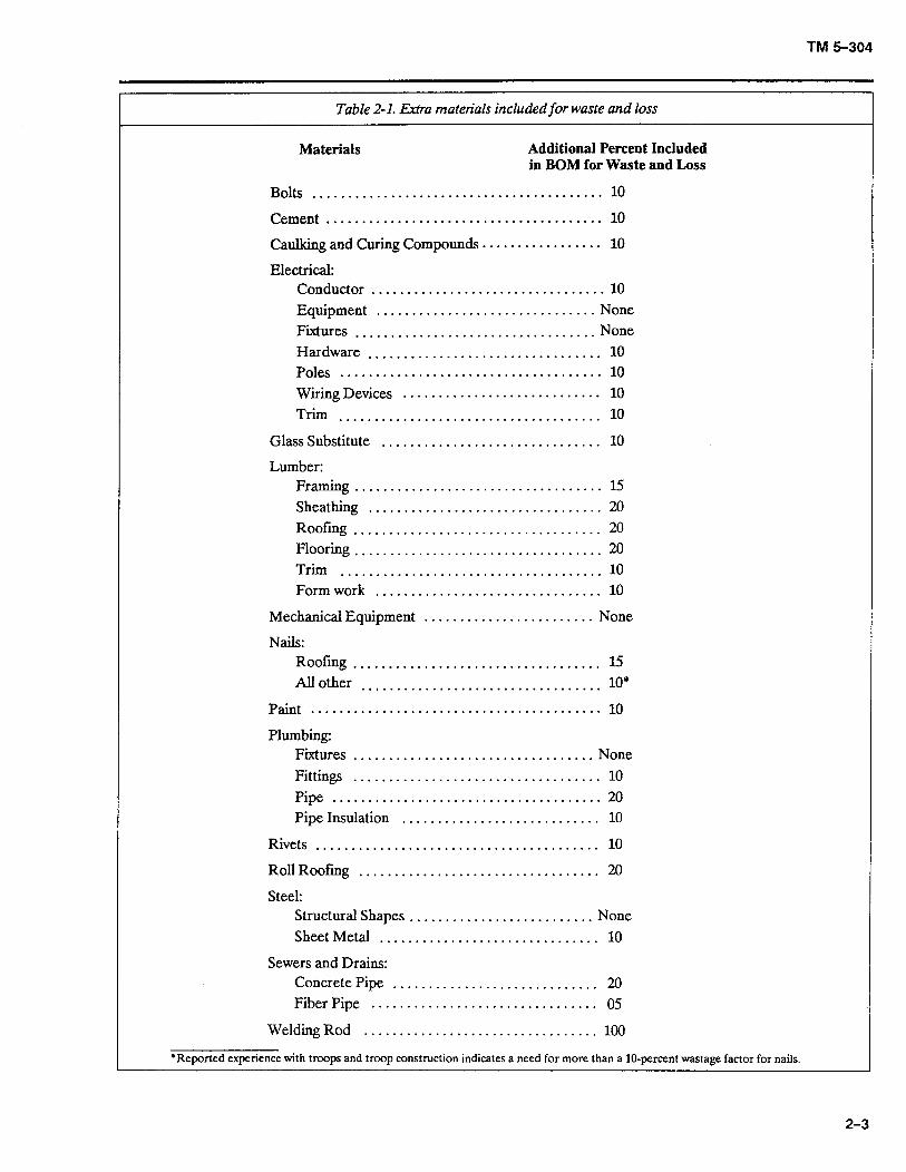
2-7. MATERIAL WASTE AND LOSS
Allowances are made for losses from breakage during handling and waste during cutting and fitting. Table 2-l lists the percentage of extra materials included.
2-8. CLIMATIC ZONES
In order to provide safe, effective, and habitable shelters, all AFCS designs take into consideration the climate of the facility’s intended use. AFCS facilities are designed to operate in one or more of four main climatic zones: temperate, tropical, frigid, and desert. Appendix D ex- plains those climatic zones in detail.
2-2
2-9. CONSTRUCTION EFFORT
The TM 5-301 series gives the estimated construction man-hours required to erect or construct each facility or installation. Those estimates are based on the use of standard construction practices and procedures promul- gated by the Engineer School; the estimates do not, how- ever, include administration, mobilization, planning, or work lost by weather delays. The estimates do include the actual construction time required for skilled and un- skilled personnel working in and major equipment operated in the temperate zone. Estimates for other climatic zones were obtained with the following adjust- ment factors:
l Temperate . . . . . . . . 1.00 (base)
l Tropical . . . . . . . . . . 1.45
l Desert . . . . . . . . . . . .1.25
l Frigid . . . . . . . . . . . . . 2.41
The various categories of labor that may be involved in a project’s construction are described in paragraphs a through c below.
a. k$ticaI Labor: The vertical labor category includes skilled specialties such as:
l Carpenter/mason
l Electrician
l Plumber
l Diver
l Metal worker
l Pipeline specialist
b. Horizontal Lubol: The horizontal labor category generally includes equipment operators such as:
l Lift/load equipment operator
l Construction equipment operator
l General construction machinery operator
l Dump truck operator
l Concrete/asphalt paving equipment operator
l Quarry machine operator
l Lightweight vehicle/power generator mechanic
c. General Labor: The general labor category includes all unskilled workers assisting horizontal or vertical laborers. General laborers perform tasks requiring no prior training or skill or use of mechanical or electrical equipment.
TM 5-304
Table 2-l. Extra materials included for waste and loss
Materials Additional Percent Included in BOM for Waste and Loss
Bolts ......................................... 10
Cement ....................................... 10
caulking and Curing Compounds ................. 10
Electrical: Conductor ................................. 10 Equipment ............................... None Fixtures ................................ ..Non e Hardware ................................. 10 Poles ..................................... 10 W&g Devices ............................ 10
Trim ..................................... 10
Glass Substitute ............................... 10
Lumber: Framing ................................... 15 Sheathing ................................. 20 Roofing.. ................................. 20 Flooring ................................... 20 Trim ..................................... 10 Form work ................................ 10
MechanicA Equipment ........................ None
Nails: Roofing.. ................................. 1.5 All other 10* ..................................
Paint.. ....................................... 10
Plumbing: Fixtures .................................. None Fittings ................................... 10 Pipe ...................................... 20 Pipe Insulation ............................ 10
Rivets ........................................ 10
RollRoofing .................................. 20
Steel: Structural Shapes .......................... None Sheet Metal ............................... 10
Sewers and Drains: Concrete Pipe ............................. 20 Fiber Pipe ................................ 05
Welding Rod ................................. 100
*Reported experience with troops and troop construction indicates a need for more than a IO-percent wastage factor for nails.
2-3
TM 5-304
Table 2-2. Ranges for operational conditions
Air Temperature Ambient Conditions Relative Solar Radiation Btu/f’t2/br OF Humidity 9%
Temperate Zone: Intermediate Hot Dry 70 to 110 24lto85 0 to360 Intermediate Cold -5 to -25 tending toward saturation negligible
Tropical Zone: Wet Warm 75 95 to loo negligible Wet Hot 78 to 95 74 to loo 0 to 360
Frigid Zone: Cold -35 to 50 tending toward saturation negligible
Desert Zone: Humid Hot Coastal Desert 85 to 100 63to90 0 to 360 Hot Dry 9oto125 5 to 20 0 to 360
2-10. ENGINEER UNIT CAPABILITIES
a. Derivation of Pmductivity. Through the use of DA guidance, the productive capabilities of various engineer units have been estimated in terms of man-hours per month. The productive capabilities of various engineer units (summarized in appendix E) were derived by (1) deducting the nonproductive units from the overall number of units for administrative, maintenance, mess, communication, and medical personnel and operators of administrative vehicles and (2) degrading the overall unit numbers by enemy actions and movement factors as shown in AR 570-2. The work period for all units is 10 hours per day, 7 days per week, 365 days per year. The functional skill groups listed in appendix E should not be interpreted as the sum total of skills available in the unit, but only as an indicator of unit capabilities. For more details on mission, assignment, and capabilities of each engineer unit, refer to FM 101-10-2
b. Reduced Prodxtivi@. The productive capabilities indicated in paragraph a above do not take into consideration several other aspects of unit capabilities. Additional reductions in the productive capabilities of engineer units can result from equipment processing following debarkation, area orientation, job organization, and acclimation of troops because of a change in climate and significant changes in altitude. As a conservative guide, productivity should decrease by 70 percent during the first 15 days when acclimation, equipment processing, area orientation, and job orientation are involved. When acclimation is not a factor, productivity should decrease by only 50 percent during the first 15 days.
2-I 1. LOGISTICAL AND COST INFORMATION
a. The material cost data and logistical data shown in TM 5-303 (BOM) are current as of the date of publication. Transportation costs for shipment are not included.
b. The user must be careful when unpacking materials and equipment. The user should check for missing materials immediately so that requisition procedures can be started, if necessary. Also, since the length of certain structural members is critical, components such as columns and certain roof truss pieces and roof and floor joists should be set aside in order to ensure that they are not cut up for use as smaller pieces. The user should also ensure that packing materials are removed carefully and not damaged, since those materials may be items (such as furring strips, etc.) needed for construction.
c. Aggregates for concrete cannot be requisitioned horn TM 5-303 (BOM). AFCS logistics data is based on the assumption that aggregates will be available within 5 miles of the construction site and can be acquired locally. Construction planners should ensure that necessary aggregates are available when the site is known.
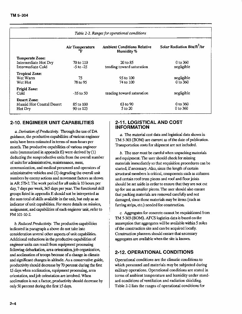
2-12. OPERATIONAL CONDITIONS
Operational conditions are the climatic conditions to which personnel and materials may be subjected during military operations. Operational conditions are stated in terms of ambient temperature and humidity under stand- ard conditions of ventilation and radiation shielding. Table 2-2 lists the ranges of operational conditions for
2-4
TM 5-304
Table 2-3. Storage and transit conditions
Temperate Zone: Intermediate Hot Dry Intermediate Cold
Tropical Zone: Wet Warm Wet Hot
Frigid Zone: Cold
Desert Zone: Humid Hot Coastal Desert Hot Dry
Induced Air Temperature OF
70 to 145 -10 to -30
80 !3oto160
-35 to -50
90t0160 90to160
Induced Relative Humidity 5%
5to50 tending toward saturation
95 to loo 10 to 85
tending toward saturation
10 to 85 2to50
each climatic region. The temperature of any type of material may vary considerably from the operational temperature because of the effects of solar radiation, shading, internal heat sources, thermal mass, and heat- transfer characteristics.
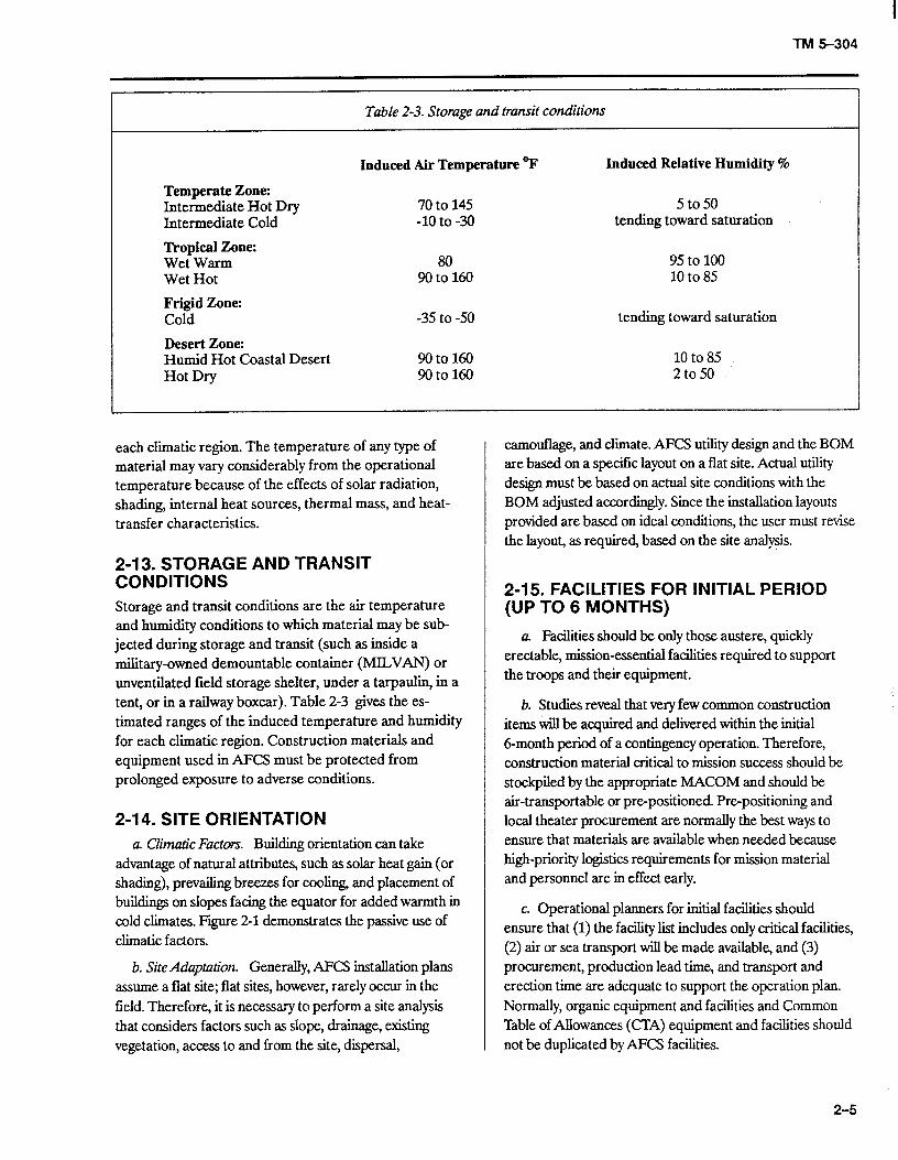
2-13. STORAGE AND TRANSIT CONDITIONS Storage and transit conditions are the air temperature and humidity conditions to which material may be sub- jected during storage and transit (such as inside a military-owned demountable container (MILVAN) or unventilated field storage shelter, under a tarpaulin in a tent, or in a railway boxcar). Table 2-3 gives the es- timated ranges of the induced temperature and humidity for each climatic region. Construction materials and equipment used in AFCS must be protected from prolonged exposure to adverse conditions.
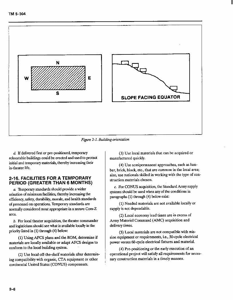
2-I 4. SITE ORIENTATION a. Climatic Factors Building orientation can take
advantage of natural attributes, such as solar heat gain (or shading), prevailing breezes for cooling, and placement of buildings on slopes facing the equator for added warmth in cold climates. Fiie 2-l demonstrates the passive use of climatic factors.
b. SiteAdaptation. Generally, AFCS installation plans assume a flat site; flat sites, however, rarely occur in the field. Therefore, it is necessary to perform a site analysis that considers factors such as slope, drainage, existing vegetation, access to and from the site, dispersal,
camouflage, and climate. AFCS utility design and the BOM are based on a specific layout on a flat site. Actual utility design must be based on actual site conditions with the BOM adjusted accordingly. Since the installation layouts provided are based on ideal conditions, the user must revise the layout, as required, based on the site analysis.
2-15. FACILITIES FOR INITIAL PERIOD (UP TO 6 MONTHS)
a. Facilities should be only those austere, quickly erectable, mission-essential facilities required to support the troops and their equipment.
b. Studies reveal that very few common construction items will be acquired and delivered within the initial o-month period of a contingency operation. Therefore, construction material critical to mission success should be stockpiled by the appropriate MACOM and should be air-transportable or pre-positioned. Pre-positioning and local theater procurement are normally the best ways to ensure that materials are available when needed because high-priority logistics requirements for mission material and personnel are in effect early.
c. Operational planners for initial facilities should ensure that (1) the facility list includes only critical facilities, (2) air or sea transport will be made available, and (3) procurement, production lead time, and transport and erection time are adequate to support the operation plan. Normally, organic equipment and facilities and Common Table of Allowances (CIA) equipment and facilities should not be duplicated by AFCS facilities.
2-5
TM5-304
W E
S SLOPE FACING EQUATOR
, .
Figure 2-l. Building orientation
d If delivered frost or pre-positioned, temporary relocatable buildings could be erected and used to protect initial and temporary materials, thereby increasing their in-theater life.
2-16. FACILITIES FOR A TEMPORARY PERIOD (GREATER THAN 6 MONTHS)
a. Temporary standards should provide a wider selection of minimum facilities, thereby increasing the efficiency, safety, durabiity, morale, and health standards of personnel on operations. Temporary standards are normally considered most appropriate in a secure Corn-2 area.
b. For local theater acquisition, the theater commander and logisticians should see what is available locally in the priority listed in (1) through (4) below:
(1) Using AFCS plans and the BOM, determine if materials are locally available or adapt AFCS designs to conform to the local building system.
(2) Use local off-the-shelf materials after determin- ing compatibility with organic, CIA equipment or other continental United States (CONUS) components.
(3) Use local materials that can be acquired or manufactured quickly.
(4) Use semipermanent approaches, such as lum- ber, brick, block, etc., that are common in the local area; also, use nationals skilled in working with the type of con- struction materials chosen.
c. For CONUS acquisition, the Standard Army supply systems should be used when any of the conditions in paragraphs (1) through (4) below exist:
(1) Needed materials are not available locally or supply is not dependable.
(2) Local economy lead times are in excess of Army Materiel Command (AMC) acquisition and delivery times.
(3) Local materials are not compatible with mis- sion equipment or requirements, i.e., 50-cycle electrical power versus 60-cycle electrical fixtures and material.
(4) Pre-positioning or the early execution of an operational project will satisfy all requirements for neces- sary construction materials in a timely manner.
2-6
TM 5-304
CHAPTER 3
OVERVIEW OF TM 5301, TM 5302, TM 5303, AND THE TACAPS USER GUIDE
3-1. GENERAL
This chapter explains the purpose and content of each of the AFCS manuals. Also, for those who are not en- gineers, a brief section is included on the use of construc- tion drawings. Furthermore, since some new and typical AFCS designs will contain a critical path method (CPM) network, a brief section describing CPM and how it can be used to control actual construction is provided.
3-2. USE OF TM 5-301
a. Purpose. TM 5-301 is a planning document that provides material costs and logistical and engineering data needed to plan theater construction. TM 5-301 is in- tended for use by those listed in paragraphs (I) through (3) below:
(1) Contingency, base development, construction, and logistical planners.
(2) Construction units (since the manual contains the engineering data required for construction of the various structures, facilities, installations, and utilities re- quired by the Army and Air Force for the support of military missions in the theater).
(3) Logistical commands and supply agencies for requisitioning, identifying, costing, and other related supply functions.
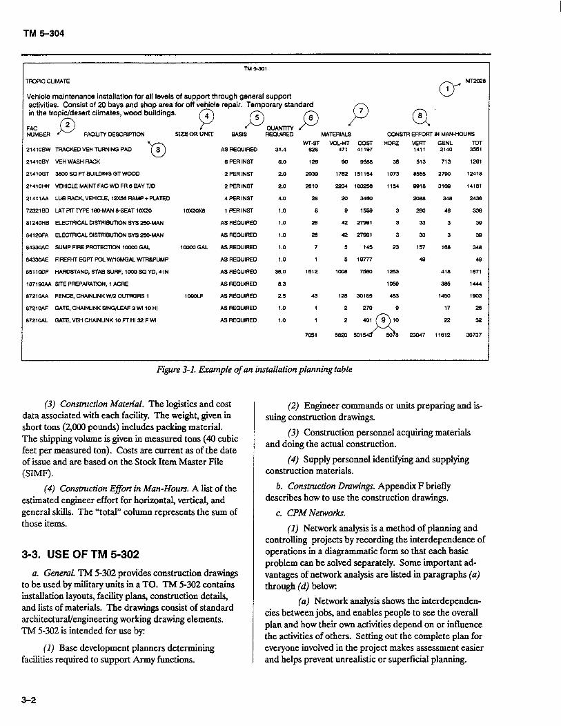
b. Installation Planning Tables. The term “planning tables” describes data published in TM 5-301 under the category of installations or facilities. (See figure 3-l for an example of an installation planning table.) Installa- tions are shown in the ascending order by the installation number in the upper right-hand corner, which consists of two alpha and four numeric characters (such as ARl.511). The number identifies the complete BOM re- quired to construct that installation. The installation description appears in the upper left-hand corner and in- cludes the title, standard and type of construction, pur- pose, and other information as needed. The tables contain the items listed in paragraphs (I) through (9) below, which coordinate with the circled numbers in fig- ure 3-l:
(1) Drawing Number. TM 5-302, volume 1, con- tains the installation drawings, which are listed in the al- phanumeric sequence by installation numbers.
(2) Facility Number. Five numeric and two alpha characters identifying each AFCS facility (such as 21410BW). The five numeric characters are the con- struction category codes from AR 415-28.
(3) Facility Description. A brief description of the facilities included in the installation.
(4) Size or Unit. Dimensions, capacity, or unit of measure for each installation facility.
(5) Basis. The criteria or standard planning basis on which facilities are included in the installation.
(6) Quantity Required. The quantity needed of a particular installation facility.
(7) Materials. The total materials, logistics, and cost data associated with the number of facilities. Weight is shown in short tons (ST) ( 2,000 pounds) and volume in measured tons (MT) (40 cubic feet per measured ton).
(8) Construction Man-Hours. The estimated horizontal, vertical, and general construction man-hours.
(9) Installation Totals. The materials, logistics, and cost data and the construction effort totals shown at the end of each table. (Note that costs listed are current only at the time of publication.)
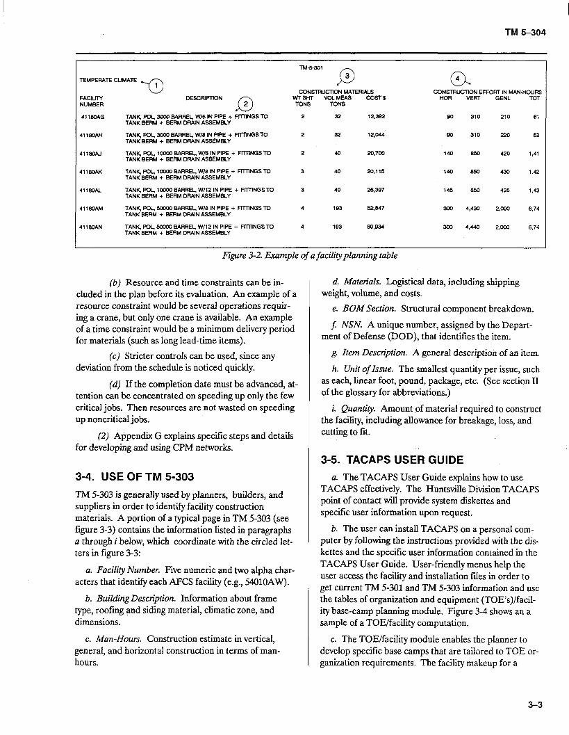
c. Facility Planning Tables. Another feature of TM 5- 301 is the facility planning tables (see figure 3-2 for an ex- ample). AFCS facilities are identified by their application in a TO. The tables contain the items listed in paragraphs (1) through (4) below, which coordinate with the circled numbers in figure 3-2:
(1) Facility Number. Five numeric and two alpha characters that identify each facility (such as 41180AG). The TM 5-302 numbering system uses the entire facility number for the corresponding construction drawing; however, there is not a drawing for every facility number.
(2) Description. A detailed description of each facility. TM 5-303 provides a detailed BOM for each facility; TM 5-302 provides construction drawings and drawings for utilities (electric, sewage, and water).
3-l
TM 5-304
TM-1
n?CPIC CUMA~
Vehicle maintenance installation for all levels of support through general support activities. Consist of 20 bays and shop area for off vehicle repair. Temporary standard in the tropic/desert climates, wood buildings.
0”
MT2u28
1
FAC D
2 p p $3 P a’
NUMBER FAClllM OESCRlFTlON SIZE OR UNn BASIS R”Z MATERIALS CCNSTR EFFORT IN MAN-HOURS
-cl
WT-ST VOL.MT COST HORZ VERT GENL TOT 2141OBW TRACKED VEH TURNING PA0 3 AS REQUIRED 31.4 828 471 41187 1411 2140 3551
2141 OBY VEH WASH RACK BPERINST 8.0 128 a0 a58a 35 513 713 1261
21410GT 3EOOSQFTBUllMNGGTWCOO 2 PER INST 2.0 2u30 1762 151154 1073 8555 2780 12418
21410HN VEHICLE MAINT FAC WO FR 8 SAY T/D 2 PER INST 2.0 2810 2234 183256 1154 8818 3109 14181
21411AA LUBRAC~VEHICLE,12X56RAMP+F?ATEO 4 PER INST 4.0 28 20 3460 2ca8 348 2438
7232180 LATPiTTYPEl~MAN&SEAT10K2O loxzox8 1 PER INST 1.0 a 9 1559 3 290 46 338
8124OHE ELECTFllCAL OISTRlBUllON SYS 250.MAN As REQUIRED 1.0 28 42 27981 3 33 3 38
8412oFA ELECTRICAL MSTRiEU-TlCN SYS 250-MAN AS REQUIRED 1.0 28 42 27991 3 33 3 39
8433OAC SUMP FIRE PROTECTION loo00 GAL 1OOWGAL AS REQUIRED 1.0 7 5 145 23 157 188 348
34330AE FIREFHT EQPT POL W/lOMGAL WlR6PUMP AS REQUlRED 1.0 1 5 16777 4s 49
851lOOF HAROSTANO, STAB SURF, loo0 SC YO, 4 IN AS RECUIREO 36.0 1512 1008 7560 1253 418 1671
1871SOAA SITE PREPARATION, 1 ACRE AS REQUIRED 8.3 1WQ 385 1444
8721OAA FENCE, CHAINLINK W/2 CUTPGRS 1 lOGOLF AS REQUIRED 2.5 43 128 30185 453 1450 1903
EMlOAF GATE, CHAINUNKSINGAEAF 3 Wl 10 HI AS REQUIRED 1.0 1 2 279 9 17 26
B721OAL GATE, VEH CHAINUNK 10 FT HI 32 FWl AS REQUIRED 1.0 1 2 22 32
7051 !582u 501 11812 38737
Figure 3-1. Example of an installation planning table
(3) Construction Material. The logistics and cost data associated with each facility. The weight, given in short tons (2,000 pounds) includes packing material. The shipping volume is given in measured tons (40 cubic feet per measured ton). Costs are current as of the date of issue and are based on the Stock Item Master File (SIMF).
(4) Construction Effort in i&n-Hours. A list of the estimated engineer effort for horizontal, vertical, and general skills. The “total” column represents the sum of those items.
3-3. USE OF TM 5-302
a. General. TM 5-302 provides construction drawings to be used by military units in a TO. TM 5-302 contains installation layouts, facility plans, construction details, and lists of materials. The drawings consist of standard architectural/engineering working drawing elements. TM 5-302 is intended for use by:
(I) Base development planners determining facilities required to support Army functions.
(2) Engineer commands or units preparing and is- suing construction drawings.
(3) Construction personnel acquiring materials and doing the actual construction.
(4) Supply personnel identifying and supplying construction materials.
b. Construction Drawings. Appendix F briefly describes how to use the construction drawings.
c. CPM Networks.
(1) Network analysis is a method of planning and controlling projects by recording the interdependence of operations in a diagrammatic form so that each basic problem can be solved separately. Some important ad- vantages of network analysis are listed in paragraphs (a) through (d) below:
(a) Network analysis shows the interdependen- ties between jobs, and enables people to see the overall plan and how their own activities depend on or influence the activities of others. Setting out the complete plan for everyone involved in the project makes assessment easier and helps prevent unrealistic or superficial planning.
3-2
TM 5-304
TEMPERATE CUMATE
-0 1
FACILll-Y DESCRIPTION NUMBER
0 2
4116OAG TANK POL, 3000 BARREL, W/B IN PIPE + FllllNGS TO TANK BERM + BERM DRAIN ASSEMBLY
4116OAH TANK POL, 3000 BARREL, W/6 IN PIPE + Frl-llNGS TO TANK BERM + BERM DRAIN ASSEMBLY
4116oAl TANK, POL. lWO0 BARREL, W/6 IN PIPE + FrlllNGS TO TANK BERM + BERM DRAIN ASSEMBLY
4116oAK TANK, pal, loo00 BARREL. W/6 IN PIPE + FllllNGS TO TANK BERM + BERM DRAIN ASSEMBLY
41160AL TANK, FOL. loo00 BARREL, W/12 IN PIPE + FllTlNGS TO TANK BERM + BERM DRAIN ASSEMBLY
4116OAM TANK, F’OL. 50000 BARREL W/8 IN PIPE + FITTINGS TO TANK BERM + BERM DRAIN ASSEMBLY
4116oAN TANK, POL, 50000 BARREL, W/12 IN PIPE + FITTINGS TO TANK BERM + BERM DRAIN ASSEMBLY
TM-5301
P
3
CONSTFlLJCllON MATERIALS WTSM VOL MEAS 5XT L
TONS TONS
2 32 12,382
2 32 12,044
2 40 20,700
3 40 20,115 140 6% 430 1.42
3 40 26,367
4 193 52,847 300 4,430 2.~ 6,74
4 193 60,934
o-. 4
CONSTRUCTION EFFOFIT IN MAN-HOURS HOR VERT GENL TOT
so 310 210 61
Bo 310 220 62
140 650 420 1.41
145 650 435 1,43
300 4,440 w3J 6.74
Figure 3-2. Example of a facility planning table
(b) Resource and time constraints can be in- cluded in the plan before its evaluation. An example of a resource constraint would be several operations requir- ing a crane, but only one crane is available. An example of a time constraint would be a minimum delivery period for materials (such as long lead-time items).
d. Materials. Logistical data, including shipping weight, volume, and costs.
(c,J Stricter controls can be used, since any deviation from the schedule is noticed quickly.
(d) If the completion date must be advanced, at- tention can be concentrated on speeding up only the few critical jobs. Then resources are not wasted on speeding up noncritical jobs.
(2) Appendix G explains specific steps and details for developing and using CPM networks.
e. BOMSection. Structural component breakdown.
JY NSN. A unique number, assigned by the Depart- ment of Defense (DOD), that identifies the item.
g. Item Description. A general description of an item.
h. Unit oflssue. The smallest quantity per issue, such as each, linear foot, pound, package, etc. (See section II of the glossary for abbreviations.)
i. Quantity. Amount pf material required to construct the facility, including allowance for breakage, loss, and cutting to lit.
3-5. TACAPS USER GUIDE
3-4. USE OF TM 5-303
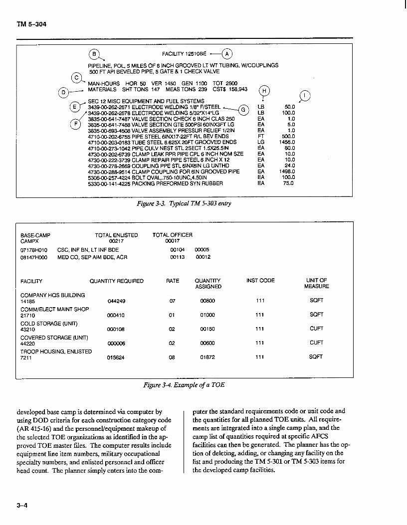
TM 5-303 is generally used by planners, builders, and suppliers in order to identify facility construction materials. A portion of a typical page in TM 5-303 (see figure 3-3) contains the information listed in paragraphs a through i below, which coordinate with the circled let- ters in figure 3-3:
a. The TACAPS User Guide explains how to use TACAPS effectively. The Huntsville Division TACAPS point of contact will provide system diskettes and specific user information upon request.
a. Facility Number. Five numeric and two alpha char- acters that identify each AFCS facility (e.g., 54OlOAW).
b. Building Description. Information about frame type, roofing and siding material, climatic zone, and dimensions.
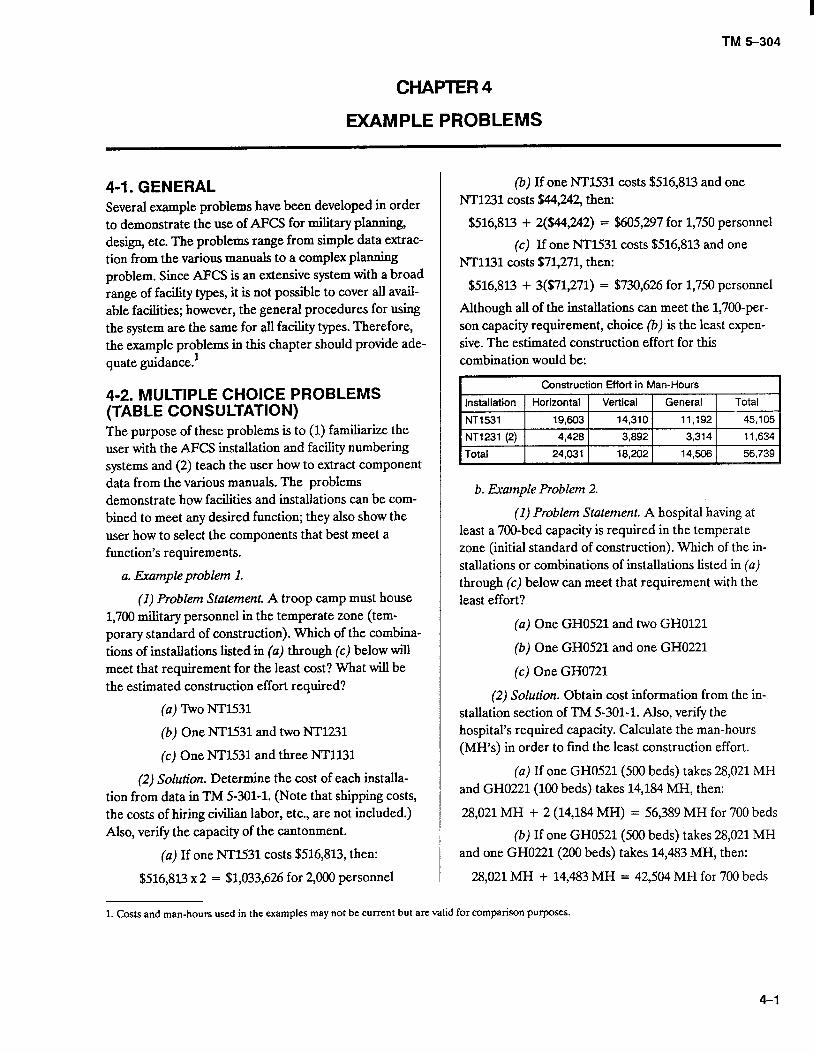
b. The user can install TACAPS on a personal com- puter by following the instructions provided with the dis- kettes and the specific user information contained in the TACAPS User Guide. User-friendly menus help the user access the facility and installation files in order to get current TM 5-301 and TM 5-303 information and use the tables of organization and equipment (TOE’s)/facil- ity base-camp planning module. Figure 3-4 shows an a sample of a TOE/facility computation.
c. Man-Hours. Construction estimate in vertical, c. The TOE/facility module enables the planner to general, and horizontal construction in terms of man- develop specific base camps that are tailored to TOE or- hours. ganization requirements. The facility makeup for a
3-3
TM 5-304
0 I3 FACILITY 12510BE \
PIPELINE, POL, 5 MILES OF 6 INCH GROOVED LT Wl TUBING, W/COUPLINGS
CL
500 FT API BEVELED PIPE, 5 GATE & 1 CHECK VALVE C
MAN-HOURS HOR 50 VER 1450 GEN 1100 TOT 2600
0 D - MATERIALS SHTTONS 147 MEASTONS 239 CST$ 158,943
0”
SEC 12 MISC EQUIPMENT AND FUEL SYSTEMS Q D E 343400-262-2671 ELECTRODE WELDING l/8” F/STEEL
d
34-262-2678 ELECTRODE WELDING 5/32”X14”LG +-@ ki 1%: ml-7487 VALVE SECTION CHECK 6 INCH CLAS 250 EA 1.0
F ml-7488 VALVE SECTION GTE 5COPSI 6OlNX3FT LG EA 5.0 3835-00-6Q3-4506 VALVE ASSEMBLY PRESSUR RELIEF 1/2lN EA 1.0 471~202-6755 PIPE STEEL 6lNX17-22FT R/L BEV ENDS Fr 500.0 47lO-C0-203-0183 TUBE STEEL 6.625X 2UFf GROOVED ENDS LG 1456.0 4710-@273-1042 PIPE CULV NEST STL PSECT 1.5X25.5lN 80.0 473O-CXIb202-6739 CLAMP LEAK RPR PIPE CPL 6 INCH NOM SZE E 10.0 473O-GO.2223739 CLAMP REPAIR PIPE STEEL 6 INCH X 12 473C4lO-278-2669 COUPLING PPE STL 61NX6lN LG UNTHD z
10.0 24.0
4730-00-288-9514 CLAMP COUPLING FOR 61N GROOVED PIPE 5306-00-257-4224 BOLT OVAL,.750-lOUNC,45OIN 533CK10-141-4225 PACKING PREFORMED SYN RUBBER
Figure 3-3. Typical TM 5-303 entry
1498.0 E loo.0 EA 75.0
1 BASE-CAMP TOTAL ENLISTED TOTAL OFFICER CAMPX 00217 ocm7
07178HOlO CSC, INF BN, LT INF BDE 00104 08147HCOO MED CO, SEP AIM BDE, ACR 00113
FACILITY QUANTITY REQUIRED RATE
COMPANY HQS BUILDING 14185
COMM/ELECT MAINT SHOP 21710
COLD STORAGE (UNIT) 43210
COVERED STORAGE (UNIT) 44220
TROOP HOUSING, ENLISTED 7211
044249
ooo410
000108
015624
07
01
02
02
08
cm05 oco12
QUANTITY INST CODE UNIT OF ASSIGNED MEASURE
111 SQFT
OlooO 111 SQFT
00150 111 cum
111 CUFr
01872 111 SOFT
J Figure 3-4. Example of a TOE
developed base camp is determined via computer by puter the standard requirements code or unit code and using DOD criteria for each construction category code the quantities for all planned TOE units. All require- (AR 415-16) and the personnel/equipment makeup of ments are integrated into a single camp plan, and the the selected TOE organizations as identified in the ap- camp list of quantities required at specific AFCS proved TOE master files. The computer results include facilities can then be generated. The planner has the op- equipment line item numbers, military occupational tion of deleting, adding, or changing any facility on the specialty numbers, and enlisted personnel and officer list and producing the TM 5-301 or TM 5-303 items for head count. The planner simply enters into the com- the developed camp facilities.
3-4
TM 5-304
CHAPTER4
EXAMPLE PROBLEMS
(b) If one NT1531 costs $516,813 and one NT1231 costs $44,242, then:
$516,813 + 2($44,242) = $605,297 for 1,750 personnel
(c) If one NT1531 costs $516,8l3 and one NT1131 costs $71,271, then:
$516,813 + 3($71,271) = $730,626 for 1,750 personnel
Although ah of the installations can meet the 1,700-per- son capacity requirement, choice (b) is the least expen- sive. The estimated construction effort for thii combination would be:
I Construction Effort in Man-Hours
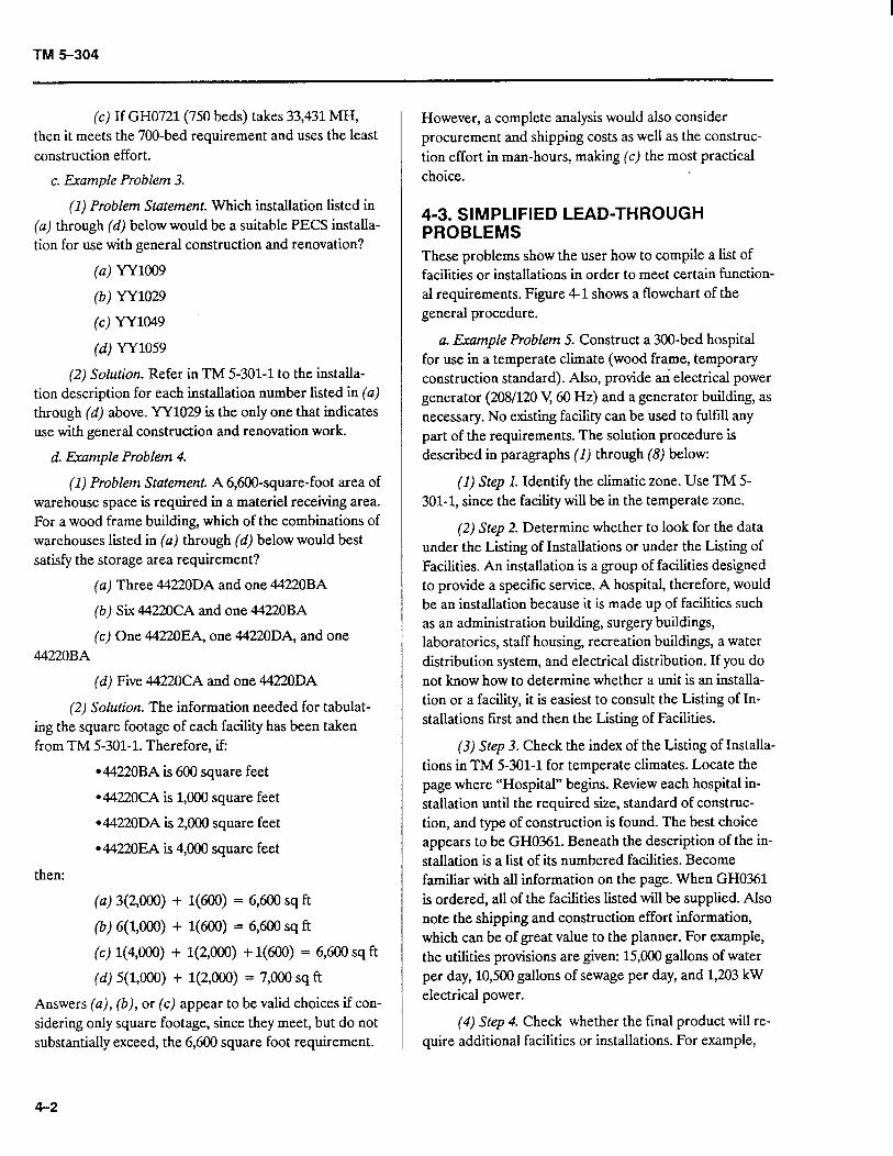
4-1. GENERAL Several example problems have been developed in order to demonstrate the use of AFCS for military planting, design, etc. The problems range from simple data extrac- tion from the various manuals to a complex planning problem. Since AFCS is an extensive system with a broad range of facihty types, it is not possible to cover all avail- able facilities; however, the general procedures for using the system are the same for all facihty types. Therefore, the example problems in this chapter should provide ade- quate guidance:
4-2. MULTIPLE CHOICE PROBLEMS (TABLE CONSULTATION) The purpose of these problems is to (1) familiarize the user with the AFCS installation and facility numbering systems and (2) teach the user how to extract component data from the various manuals. The problems demonstrate how facilities and installations can be com- bined to meet any desired function; they also show the user how to select the components that best meet a function’s requirements.
a. Example problem 1.
b. Example Problem 2.
(1) Problem Statement. A troop camp must house 1,700 military personnel in the temperate zone (tem- porary standard of construction). Which of the combina- tions of instahations listed in (a) through (c) below will meet that requirement for the least cost? What will be the estimated construction effort required?
(a) lb0 NT1531
(1) Problem Statement. A hospital having at least a 700-bed capacity is required in the temperate zone (initial standard of construction). Which of the in- stallations or combinations of installations listed in (a) through (c) below can meet that requirement with the least effort?
(a) One GH0521 and two GH0121
(b) One GH0521 and one GH0221
(c) One GH0721
(b) One NT1531 and two NT1231
(c) One NT1531 and three NT1131
(2) Solution. Determine the cost of each installa- tion from data in TM 5-301-l. (Note that shipping costs, the costs of hiring civilian labor, etc., are not included.) Also, verify the capacity of the cantonment.
(a) If one NT1531 costs $516,813, then:
$516,813 x 2 = $1,033,626 for 2,000 personnel
(2) Solution. Obtain cost information from the in- stallation section of TM 5-301-l. AIso, verify the hospital’s required capacity. Calculate the man-hours (MH’s) in order to find the least construction effort.
(u) If one GH0521(500 beds) takes 28,021 MH and GH0221(100 beds) takes 14,184 MH, then:
28,021 MH + 2 (14,184 MH) = 56,389 MH for 700 beds
(b) If one GH0521(500 beds) takes 28,021 MH and one GH0221(200 beds) takes 14,483 MH, then:
28,021 MH + 14,483 MH = 42,504 MH for 700 beds
1. Costs and man-hours used in the examples may not be current but are valid for comparison purposes.
4-l
TM 5-304
(c) If GH0721(750 beds) takes 33,431 MH, then it meets the 700-bed requirement and uses the least construction effort.
c. Example Problem 3.
(1) Problem Statement. Which installation listed in (a) through (d) b e 1 ow would be a suitable PECS installa- tion for use with general construction and renovation?
(a) YY1009
(b) YY1029
(c) YY1049
(d) YY1059
(2) Solution. Refer in TM 5-301-l to the installa- tion description for each installation number listed in (a) through (d) above. YY1029 is the only one that indicates use with general construction and renovation work.
d. Example Problem 4.
(1) Problem Statement. A 6,600-square-foot area of warehouse space is required in a materiel receiving area. For a wood frame building, which of the combinations of warehouses listed in (a) through (d) below would best satisfy the storage area requirement?
(a) Three 4422ODA and one 44220BA
(b) Six 44220CA and one 44220BA
(c) One 44220EA, one 4422ODA, and one 44220BA
(d) Five 44220CA and one 44220DA
(2) Solution. The information needed for tabulat- ing the square footage of each facility has been taken from TM 5-301-l. Therefore, if:
l 44220BA is 600 square feet
l 44220CA is 1,000 square feet
l 4422ODA is 2,000 square feet
l 4422OEA is 4,000 square feet
then:
(a) 3(2,000) + l(600) = 6,600 sq ft
(b) 6(1,000) + l(600) = 6,600 sq ft
(c) l(4,OOO) + l(2,OOO) + l(600) = 6,600 sq ft
(d) 5(1,000) + l(2,OOO) = 7,000 sq ft
Answers (a), (b), or (c) appear to be valid choices if con- sidering only square footage, since they meet, but do not substantially exceed, the 6,600 square foot requirement.
4-2
However, a complete analysis would also consider procurement and shipping costs as well as the construc- tion effort in man-hours, making (c) the most practical choice.
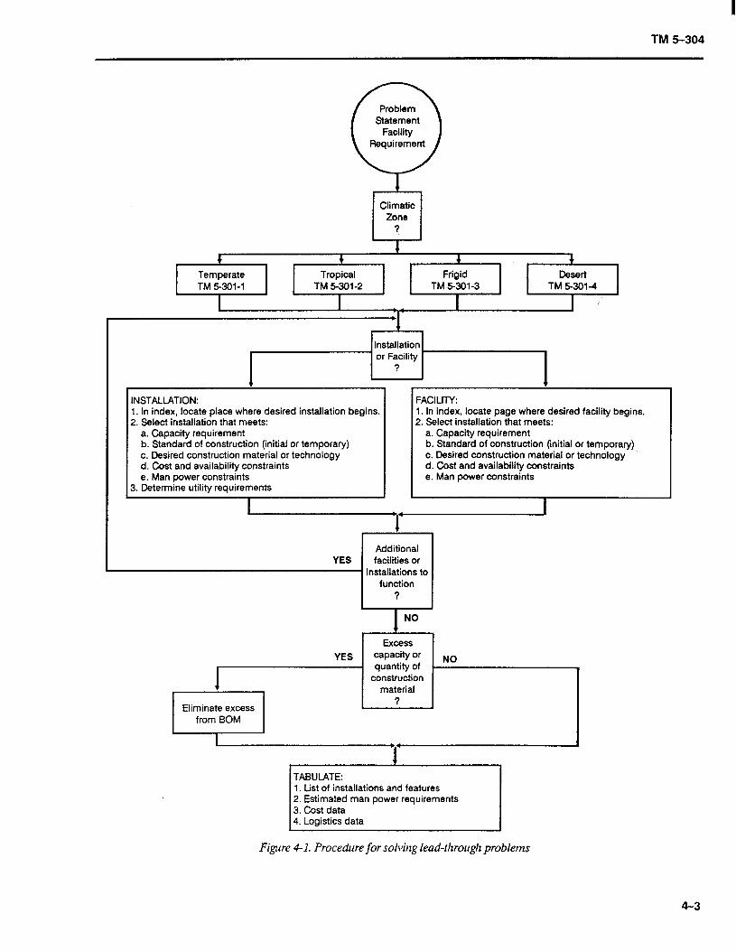
4-3. SIMPLIFIED LEAD-THROUGH PROBLEMS These problems show the user how to compile a list of facilities or installations in order to meet certain function- al requirements. Figure 4-l shows a flowchart of the general procedure.
a. Example Problem 5. Construct a 300-bed hospital for use in a temperate climate (wood frame, temporary construction standard). Also, provide an electrical power generator (208/120 V, 60 Hz) and a generator building, as necessary. No existing facility can be used to fulfill any part of the requirements. The solution procedure is described in paragraphs (1) through (8) below:
(I) Step 1. Identify the climatic zone. Use TM 5- 301-1, since the facility will be in the temperate zone.
(2) Step 2. Determine whether to look for the data under the Listing of Installations or under the Listing of Facilities. An installation is a group of facilities designed to provide a specific service. A hospital, therefore, would be an installation because it is made up of facilities such as an administration building, surgery buildings, laboratories, staff housing, recreation buildings, a water distribution system, and electrical distribution. If you do not know how to determine whether a unit is an installa- tion or a facility, it is easiest to consult the Listing of In- stallations first and then the Listing of Facilities.
(3) Step 3. Check the index of the Listing of Installa- tions in TM 5-301-l for temperate climates. Locate the page where “Hospital” begins. Review each hospital in- stallation until the required size, standard of construc- tion, and type of construction is found. The best choice appears to be GH0361. Beneath the description of the in- stallation is a list of its numbered facilities. Become familiar with all information on the page. When GH0361 is ordered, all of the facilities listed will be supplied. Also note the shipping and construction effort information, which can be of great value to the planner. For example, the utilities provisions are given: 15,000 gallons of water per day, 10,500 gallons of sewage per day, and 1,203 kW electrical power.
(4) Step 4. Check whether the final product will re- quire additional facilities or installations. For example,
TM 5-304
+ _
Climatic Zone
7
Temperate TM 5-301-l
I
Tropical TM 5301-2
I
Frigid TM 5-301-3
I
Desert TM 5301-4
1
INSTALLATION: FACILITY: 1. In index, locate place where desired installation begins. 2. Select installation that meets:
a. Capacity requirement b. Standard of construction (initial or temporary) c. Desired construction material or technology d. Cost and availability constraints e. Man power constraints
3. Determine utility requirements
1. In index, locate page where desired facility begins. 2. Select installation that meets:
a. Capacity requirement b. Standard of construction (initial or temporary) c. Desired construction material or technology d. Cost and availability constraints e. Man power constraints
I I I
Additional YES facilities or
- installations to I function I
Figure 4-1. Procedure for solving lead-through problems
4-3
TM 5-304
Table 4-1. Tabulations for example problem 5
Materials Construction Effort in Man-Hours
Weight Volume cost Horizontal Vertical General shot-t tons measured tons $
1 2,711 3,354 980,166 5,367 69,694 11,732
1 57 90 63,325 51 1,611 493
2,766 3,444 1 ,c43,513 5,438 91,305 12,225
according to paragraph a above, an electrical power generation plant should be provided.
(5) Step 5.
(a) Begin a search for the electrical generating plant. The required capacity must be at least 1,203 kW, according to the installation description. Consult the index to the Listing of Facilities in order to locate the page where “Electrical Generation and Distribution Equipment” begins. Search for a plant that provides 1,203 kW. Since the next plant larger than 1,230 kW is a 1,500-kW facility, you must decide whether it would be best to over design slightly or over design considerably.
(b) With that decision in mind, review the avail- able generating plants, 81110GA through 81110GK. Using information from the facility description and draw- ing, you can narrow the possible choices to 8111OGA, 81110GB, and 81110GC. All are temporary standard of construction facilities and each includes a building.
(c) The facility description and the schedule of facilities and drawings on sheet 81110GA-GK, sheet 1, (in TM 5-302) show, however, that for the 1,500-kW generating plant, four 500-kW generators are actually in- stalled, and for the 2,000-kW generating plant, five 500- kW generators are installed. Because of the reserve capacity of 81110GA and the fact that the peak demand of 1,203 kW would be 1.5 percent greater, the best choice would be the 1,500-kW generating plant, 81110GA.
(6) Step 6. After all of the required installations or facilities are picked, check if any existing facilities can ful- fill part of the requirement. If so, the new facilities that are redundant can be eliminated from the’list of com- ponents to be acquired.
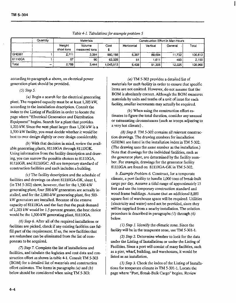
(7) Step 7. Complete the list of installations and facilities, and tabulate the logistics and cost data and con- struction effort as shown in table 4-1. Consult TM 5-303 (BOM) for a detailed list of materials and construction effort estimates. The items in paragraphs (a) and (b) below should be considered when using TM 5-303:
(a) TM 5-303 provides a detailed list of materials for each facility in order to ensure that specific items are not omitted. However, do not assume that the BOM is absolutely correct. Although the BOM measures materials by units and tenths of a unit of issue for each facility, smaller increments may actually be required.
(b) When using the construction effort es- timates to figure the total duration, consider any unusual or extenuating circumstances (such as troops adjusting to a very hot climate) .
(8) Step 8. TM S-302 contains all relevant construc- tion drawings. The drawing numbers for installation GH0361 are listed in the installation index in TM 5-302. (The drawing uses the same number as the installation.) Note that drawings for the individual facilities, such as the generator plant, are determined by the facility num- ber. For example, drawings for the generator facility 81110GA are found on 81110GA-GK in TM 5-302.
b. Example Problem 6. Construct, for a temperate climate, a port facility to handle 1,000 tons of break-bulk cargo per day. Assume a tidal range of approximately 15 feet and use the temporary construction standard and wood frame buildings. Assume that an additional 8,000 square feet of warehouse space will be required. Utilities (electricity and water) need not be provided, since they will be supplied from a nearby installation. The solution procedure is described in paragraphs (1) through (6) below.
(1) Step I. Identify the climatic zone. Since the facility will be in the temperate zone, use TM 5-301-l.
(2) Step 2. Determine whether to look for the data under the Listing of Installations or under the Listing of Facilities. Since a port will consist of many facilities, such as a pier, wharf, building, and warehouses, it would be listed as an installation.
(3) Step 3. Check the index of the Listing of Installa- tions for temperate climate in TM 5-301-l. Locate the page where “Port, Break-Bulk Cargo” begins. Review
4-4
TM 5-304
Table 4-2. Tabulations for example problem 7
each port installation until the required size, standard of construction, and type of construction are found. The best choice appears to be FF’1105.
(4) Step 4. Check whether the final product will re- quire additional facilities or installations. For example, this problem requires an additional 8,000 square feet of warehouse space.
(5) Step 5. To fill the extra warehouse space require- ments, search through the Listing of Facilities as described in step 3 of example problem 5 above, or check for the facilities listed under the selected installa- tion. Facilities that exactly match the requirements can be ordered. For instance, facility 44110EA (which is one of the components of installation FP1105) is a closed, wooden warehouse with a capacity of 4,000 square feet. The additional space required is 8,000 square feet; there- fore, ordering two additional warehouses of type 44110EA would meet the requirement.
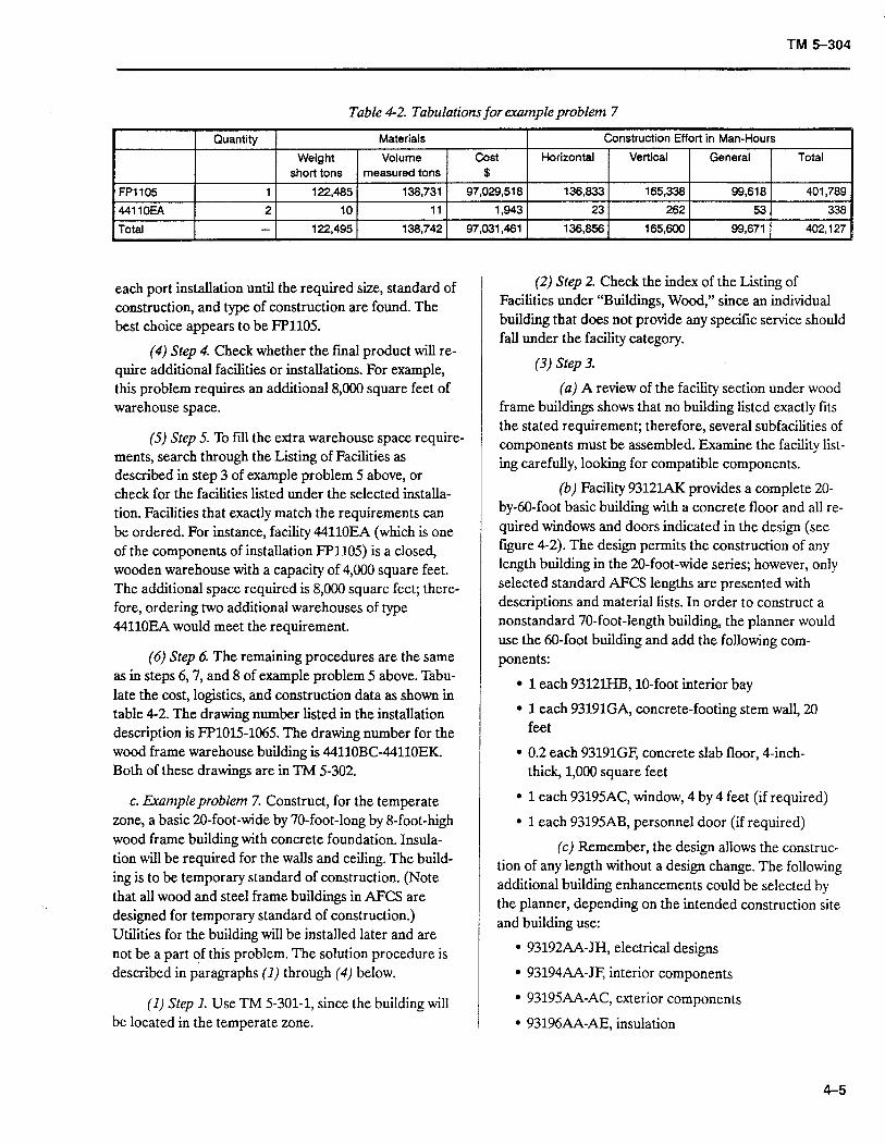
(6) Step 6. The remaining procedures are the same as in steps 6,7, and 8 of example problem 5 above. Tabu- late the cost, logistics, and construction data as shown in table 4-2. The drawing number listed in the installation description is FP1015-1065. The drawing number for the wood frame warehouse building is 44110BC-44110EK. Both of these drawings are in TM 5-302.
c. Exampleproblem 7. Construct, for the temperate zone, a basic 2O-foot-wide by 70-foot-long by 8-foot-high wood frame building with concrete foundation. Insula- tion will be required for the walls and ceiling. The build- ing is to be temporary standard of construction. (Note that all wood and steel frame buildings in AFCS are designed for temporary standard of construction.) Utilities for the building will be installed later and are not be a part of this problem. The solution procedure is described in paragraphs (1) through (4) below.
(1) Step I. Use TM 5-301-1, since the building will be located in the temperate zone.
(2) Step 2. Check the index of the Listing of Facilities under “Buildings, Wood,” since an individual building that does not provide any specific service should fall under the facility category.
(3) Step 3.
(a) A review of the facility section under wood frame buildings shows that no building listed exactly fits the stated requirement; therefore, several subfacilities of components must be assembled. Examine the facility list- ing carefully, looking for compatible components.
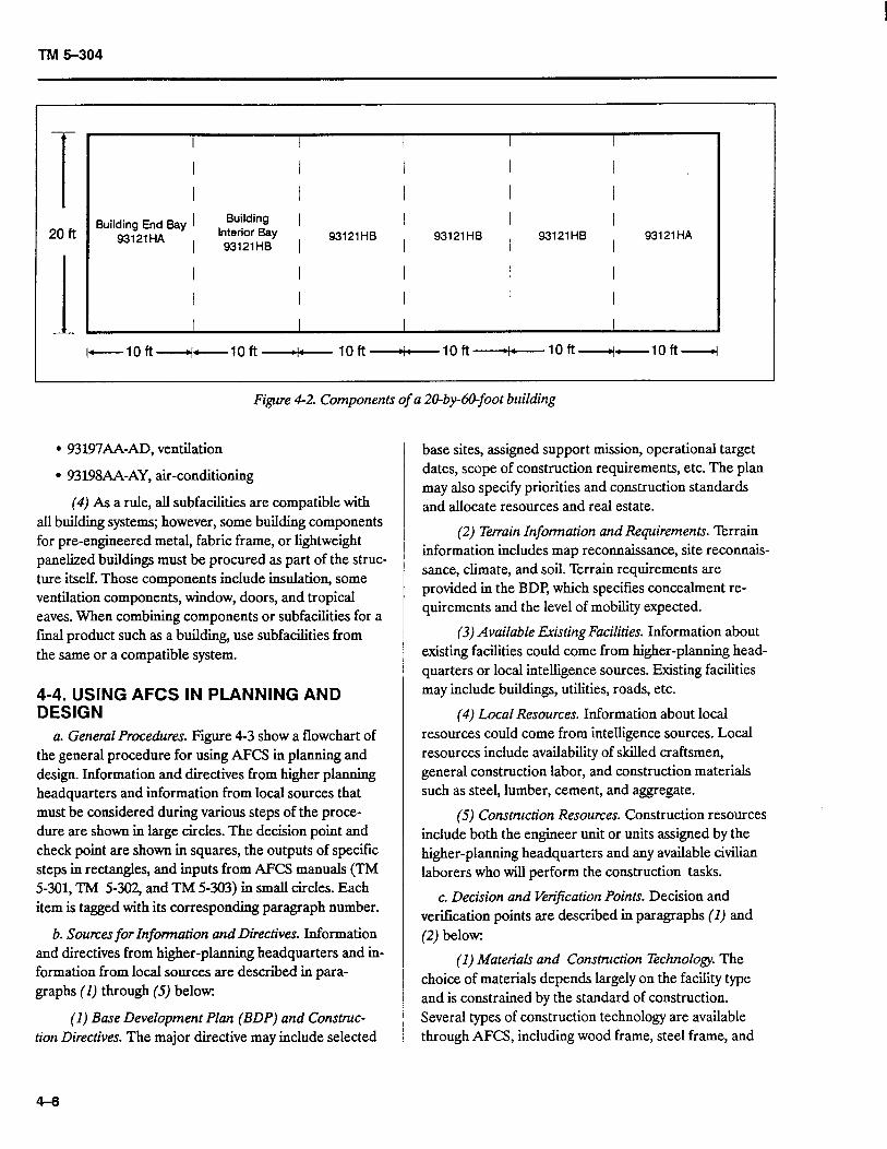
(b) Facility 93121AK provides a complete 20- by-60-foot basic building with a concrete floor and all re- quired windows and doors indicated in the design (see figure 4-2). The design permits the construction of any length building in the 20-foot-wide series; however, only selected standard AFCS lengths are presented with descriptions and material lists. In order to construct a nonstandard 70-foot-length building, the planner would use the 60-foot building and add the following com- ponents:
l 1 each 93l21HB, lo-foot interior bay
l 1 each 93191GA, concrete-footing stem wall, 20 feet
l 0.2 each 93191GF, concrete slab floor, 4-inch- thick, 1,000 square feet
l 1 each 93195AC, window, 4 by 4 feet (if required)
l 1 each 93195AB, personnel door (if required)
(c) Remember, the design allows the construc- tion of any length without a design change. The following additional building enhancements could be selected by the planner, depending on the intended construction site and building use:
l 93192AA-JH, electrical designs
l 93194AA-JF, interior components
. 93195.&A-AC, exterior components
l 93196AA-AE, insulation
4-5
TM 5-304
Figure 4-2. Components of a 20-by&-foot building
l 93197AA-AD, ventilation
l 93198AA-AY, air-conditioning
(4) As a rule, all subfacilities are compatible with all building systems; however, some building components for pre-engineered metal, fabric frame, or lightweight panelized buildings must be procured as part of the struc- ture itself. Those components include insulation, some ventilation components, window, doors, and tropical eaves. When combining components or subfacilities for a final product such as a building, use subfacilities from the same or a compatible system.
4-4. USING AFCS IN PLANNING AND DESIGN
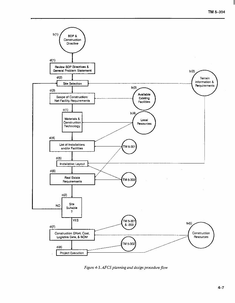
a. General Procedures. Figure 4-3 show a flowchart of the general procedure for using AFCS in planning and design. Information and directives from higher planning headquarters and information from local sources that must be considered during various steps of the proce- dure are shown in large circles. The decision point and check point are shown in squares, the outputs of specific steps in rectangles, and inputs from AFCS manuals (TM 5-301, TM 5-302, and TM 5-303) in small circles. Each item is tagged with its corresponding paragraph number.
b. Sources for Infomtation and Directives. Information and directives from higher-planning headquarters and in- formation from local sources are described in para- graphs (I) through (5) below:
(1) Base Development Plan (BDP) and Construc- tion Directives. The major directive may include selected
base sites, assigned support mission, operational target dates, scope of construction requirements, etc. The plan may also specify priorities and construction standards and allocate resources and real estate.
(2) Terrain Information and Requirements. Terrain information includes map reconnaissance, site reconnais- sance, climate, and soil. Terrain requirements are provided in the BDP, which specifies concealment re- quirements and the level of mobility expected.
(3) Available Existing Facilities. Information about existing facilities could come from higher-planning head- quarters or local intelligence sources. Existing facilities may include buildings, utilities, roads, etc.
(4) Local Resources. Information about local resources could come from intelligence sources. Local resources include availability of skilled craftsmen, general construction labor, and construction materials such as steel, lumber, cement, and aggregate.
(5) Construction Resources. Construction resources include both the engineer unit or units assigned by the higher-planning headquarters and any available civilian laborers who will perform the construction tasks.
c. Decision and Verijkation Points. Decision and verification points are described in paragraphs (1) and (2) below:
(1) Materials and Construction Technology. The choice of materials depends largely on the facility type and is constrained by the standard of construction. Several types of construction technology are available through AFCS, including wood frame, steel frame, and
4-6
TM 5-304
d(2) I ---- ~Site Selection 1 c 8
d(3) I
Scope of Construction: Net Facility Requirements
c(l)
Materials & Construction l
Technology
b(2) Terrain
information & Requirements
(I: List of Installations
and/or Facilities
Real Estate Requirements
I I YES -n TM 5-301
* 3n.Y
Construction Effort, Cost,
Figure 4-3. AFCS planning and design procedure flow
4-7
TM 5-304
prefabricated buildings. The selection of a particular building type should be based on the availability of materials, time constraints, and the types of skilled craftsmen needed.
(2) Site Suitability. The estimates of total real estate requirements are based on the final installation layouts. The results are compared with those of the previously selected or assigned sites, and then steps are taken to ac- quire any needed additional land.
d. Planning, Design, and Estimating. The planning, design, and estimating stages that generate requirements are explained in paragraphs (I) through (8) below:
(1) General Problem Statement. The BDP should be reviewed for thoroughness and consistency; then, a general problem statement should be formed. The state- ment should consist of military plans and support re- quirements in terms of the tasks to be done by the construction unit and the resources available to do them. The statement should also include information about size, location, climate, standard of construction, etc.
(2) Site Selection. The land estimate is based on the construction requirements. Information about candidate sites is evaluated, using the estimate and the terrain re- quirements. The most promising sites are inspected by a reconnaissance team, and then a site is chosen.
(3) Scope of Constmction. The net facility require- ments can be determined by examining the overall facility requirements and any usable existing facilities such as buildings, utilities, etc.
(4) List of Installations andlor Facilities. On the basis of the scope of construction requirements and the construction standard, a list of installations and facilities (identified by their numbers) can be developed. TM 5- 301 is used to select the desired installations and facilities. (See previous example problems for details.)
(5) Installation Layout. TM 5-302 gives the recom- mended layout of facilities within the installation; how- ever, the recommended layout may need to be revised to meet terrain requirements and other site-specific condi- tions such as existing buildings, roadways, utilities, and dispersal.
(6) Real Estate Requirements. TM 5-301 gives the quantity of land required for the recommended facility layout. If the recommended layouts are not used, the ac- tual required land area should be calculated based on
4-8
the revised layout. APCS installation designs are general- ly based on minimum real estate requirements.
(7) Construction Effort, Cost, Logistics Data, and BOM. TM 5-301 and TM 5-303 provide the estimated construction man-hours, cost, and logistical data for transportation; TM 5-303 also provides the BOM. The number of man-hours required for all horizontal, verti- cal, and general construction should be tabulated and compared with the number of man-hours available from construction units in each category. If there are delicien- ties, additional man power support should be requested. The total time needed to complete all construction can be estimated on the basis of the available man power and the number of man-hours required for construction.
(8) Project Execution. Project execution ends the planning steps discussed in paragraphs (1) through (7) above. The working drawings in TM 5-302 provide infor- mation of various construction resources (including en- gineer units and civilian labor) used to execute the project.
e. Example Problem 8.
(1) Problem Statement.
(a) General. A cantonment is required for five companies, or about 1,000 troops. A 55-acre site has been selected and is suitable for construction without major grading and clearance operations. The camp will be located in a temperate zone and will be turned over to allied forces at the end of hostilities; therefore, the tem- porary standard of construction would be the most suitable.
(b) Water Treatment and Dis$bution. Potable water is not available from local communities; however, intelligence sources indicate that good well water should be available within 250 feet of the surface. Water storage should be provided for about 40 to 50 percent of the daily demand as called for in the installation description.
(c) Sewage Collection and Treatment. All waste water from the camp must receive primary and secon- dary treatment before being discharged into any local streams. Local code requirements do not allow pit latrines within the cantonment; therefore, a waterborne sewage treatment facility will be required.
(d) Electrical Power and Distribution. Intel- ligence shows that the local power generation capacity is insufficient and unreliable. Assume that power genera-
TM 5-304
tion with a 30-percent emergency backup capacity will be required.
(e) Recreation and Service Requirements. As- sume that a chapel with a capacity of at least 25 percent of the camp’s population will be required. No athletic courts or theater are scheduled at this time.
cf) Roadr. There is bituminous surfacing on many roads in the vicinity, so no major road-building projects are anticipated. An abundance of good ag- gregate can be found nearby.
(g) Resources. About 300 civilians will be avail- able for general labor tasks. One line company from a combat engineer battalion (heavy) will be available to work on the project.
(2) Problem Solution. Figure 4-3 shows the proce- dure for solving this type of problem. The planning, design, and estimation stages explained in paragraphs (3) through (9) below correlate with parts d(1) through d(7) of figure 4-3.
(3) BDP-d(I). Review the BDP directives and the general problem statement and summarize the basic re- quirements.
(4) Site Selection-d(2). Since a site has been as- signed previously, no action is needed now. Later, it will be necessary to verify that the site is large enough and is suitable for constructing the project.
(5) Scope of Construction-d(3). All construction will be new, since no facilities in the area, except the roads, can fulfill any requirements of the problem state- ment.
(6) List of Installations and/or Facilities-d(4).
(a) General. The best way to approach the problem is to select from TM 5-301-l the smallest com- ponent that will satisfy the mission requirement. For this problem, the temporary standard has been specified. Begin by scanning the index of the Listing of Installations in TM 5-301-l and turn to the first page of “Camps, Troop.” Note the verbal description of each installation in the upper left-hand comer of the page. Check the list- ing page-by-page and find a l,OOO-man, temporary stand- ard, wood frame troop camp that can be used (such as installation NTl531). To determine the most suitable type of construction (steel or wood frame), consider the following: availability, engineering effort required, timeframe for completion, logistical requirements, and cost.
(b) Choice ofikfatetiak. Normally, the most im- portant consideration is the availability of materials. Since wood is usually readily available, NT1531 (wood frame) is probably the best choice, assuming the other constraints listed in (a) above are of little consequence. Based on DOD planning factors, the installation requires 25,000 gallons of water per day, generates 17,500 gallons of sewage, requires 52.1 acres of land, and requires at least 485.5 kW of electrical generation capacity.
(c) Chapel. Since the chapel building serves a specific purpose, it is listed in the facilities section. In the index of the Liiting of Facilities, find the page number for chapel listings; from that page search page-by-page until a suitable facility is found. Facility number 74018AU, a wood frame chapel with 300 seats, appears to be the best choice, since it is the smallest available facility meeting the basic requirement of seating 25 per- cent of the camp’s population.
(d) Water Treatment Plant. In the index of the Listing of Facilities, find the page number for “Water Supply and Treatment” and search page-by-page for a facility that meets the problem’s requirements. Facility 84120AB will supply up to 60,000 gallons of water per day. That facility consists of a deep-well hypochlorina- tion unit with 21,000 gallons of elevated storage, yielding a storage capacity of 84 percent (21,000 gallons storage/25,000 gallons daily demand x 100) of the total daily demand, and thus provides more than the percent- age of storage required. However, one of the two 10,500- gallon elevated storage tanks could be deleted from the facility, reducing storage to the required 40 to 50 per- cent.
(e) Sewage Treatment Plant. Select a sewage treatment plant in the same way a water treatment plant was selected in (d) above. Consider plant capacity first. TM 5-301 shows that facility 83110AA can handle 25,000 gallons per day. Since facility 8311OA4 is the first instal- lation listed exceeding the required 17,500 gallons per day and offering both primary and secondary treatment as required in the construction directive, it appears to be the best choice.
cf) Electric Generating Plant. The electric generating plants are found in the Listing of Facilities of TM 5-301. To determine the capacity of the generators, tabulate the loads of the various components to be or- dered and add an additional 30 percent as called for in the construction directive:
4-9
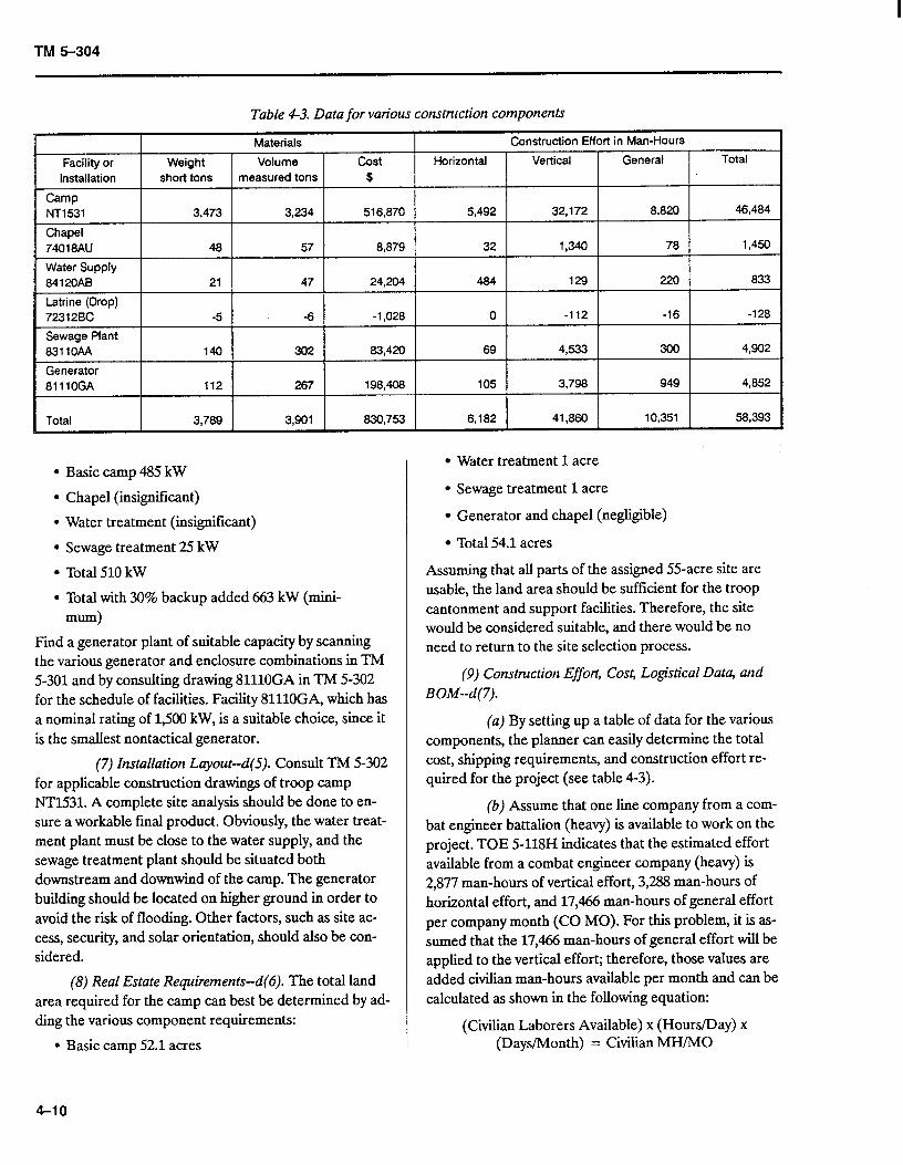
TM 5-304
Table 43. Data for various construction components
Materials Construction Effort in Man-Hours Facility or 1 Weight 1 Volume 1 cost 1 Horizontal 1 Vertical 1 General Total
Installation
Camp NT1531
Chapel 74018AtJ
Water Supply 84120AB
Latrine (Drop) 72312BC
Sewage Plant 83110AA
Generator 81110GA
short tons measured tons $
3,473 3,234 516,870 5,492 32,172 8,820 46,484
48 57 8,879 32 1,340 78 1,450
21 47 24,204 484 129 220 833
-5 -6 -1,028 0 -112 -16 -128
140 302 83,420 69 4,533 300 4,902
112 267 198,408 105 3,798 949 4,852
Total 3,789 3,901 830,753 6,182 41,860 10,351 58,393
l Basic camp 485 kW
l Chapel (insignificant)
l Water treatment (insignificant)
l Sewage treatment 25 kW
l Total 510 kW
l Total with 30% backup added 663 kW (mini- mum)
Find a generator plant of suitable capacity by scanning the various generator and enclosure combinations in TM 5-301 and by consulting drawing 81110GA in TM 5-302 for the schedule of facilities. Facility 81110GA, which has a nominal rating of 1,500 kW, is a suitable choice, since it is the smallest nontactical generator.
(7) Installation Layout-d(S). Consult TM 5-302 for applicable construction drawings of troop camp NT1531. A complete site analysis should be done to en- sure a workable final product. Obviously, the water treat- ment plant must be close to the water supply, and the sewage treatment plant should be situated both downstream and downwind of the camp. The generator building should be located on higher ground in order to avoid the risk of flooding. Other factors, such as site ac- cess, security, and solar orientation, should also be con- sidered.
(8) Real Estate Requirements--d(6). The total land area required for the camp can best be determined by ad- ding the various component requirements:
l Basic camp 52.1 acres
. Water treatment 1 acre
l Sewage treatment 1 acre
l Generator and chapel (negligible)
l Total 54.1 acres
Assuming that all parts of the assigned 55-acre site are usable, the land area should be sufficient for the troop cantonment and support facilities. Therefore, the site would be considered suitable, and there would be no need to return to the site selection process.
(9) Construction Effort, Cost, Logistical Data, and BOM--d(7).
(a) By setting up a table of data for the various components, the planner can easily determine the total cost, shipping requirements, and construction effort re- quired for the project (see table 4-3).
(b) Assume that one line company from a com- bat engineer battalion (heavy) is available to work on the project. TOE 5-118H indicates that the estimated effort available from a combat engineer company (heavy) is 2,877 man-hours of vertical effort, 3,288 man-hours of horizontal effort, and 17,466 man-hours of general effort per company month (CO MO). For this problem, it is as- sumed that the 17,466 man-hours of general effort will be applied to the vertical effort; therefore, those values are added civilian man-hours available per month and can be calculated as shown in the following equation:
(Civilian Laborers Available) x (Hours/Day) x (Days/Month) = Civilian MH/MO
4-10
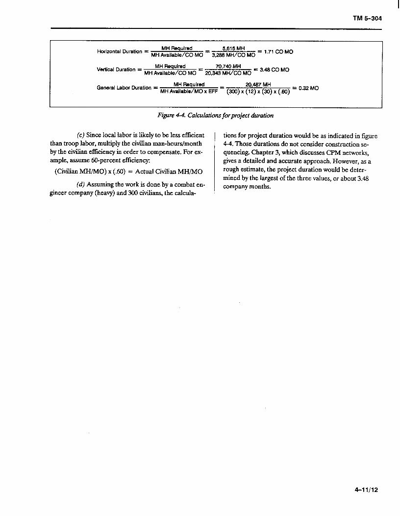
TM 5-304
Horizontal Duration = MH Required 5,615 MH
MH Available/CO MO = 3,288 MH/CO MO = 1.71 co MO
Vertical Duration = MH Required 70,740 MH
MH Available/CO MO = 20,343 MI+&0 MO = 3.48 CO MO
MH Required General Labor Duration = MH Avai,ab,e,MO x EFF =
20,487 MH
w9 x (‘2) x w x (Jw = 0.32 MO
Figure 4-4. Calculations forproject duration
(c) Since local labor is likely to be less efficient than troop labor, multiply the civilian man-hours/month by the civilian efficiency in order to compensate. For ex- ample, assume 60-percent efficiency:
(Civilian MH/MO) x (.60) = Actual Civilian MH/MO
(d) Assuming the work is done by a combat en- gineer company (heavy) and 300 civilians, the calcula-
tions for project duration would be as indicated in figure 4-4. Those durations do not consider construction se- quencing. Chapter 3, which discusses CPM networks, gives a detailed and accurate approach. However, as a rough estimate, the project duration would be deter- mined by the largest of the three values, or about 3.48 company months.
4-11/12
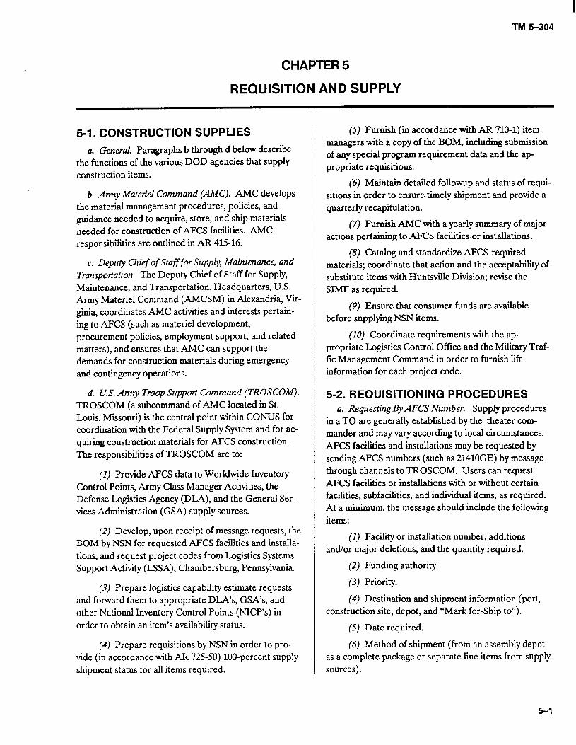
TM 5-304
CHAPTER5
REQUISITION AND SUPPLY
5-I. CONSTRUCTION SUPPLIES
a. General. Paragraphs b through d below describe the functions of the various DOD agencies that supply construction items.
b. Army Materiel Command @MC). AMC develops the material management procedures, policies, and guidance needed to acquire, store, and ship materials needed for construction of AFCS facilities. AMC responsibilities are outlined in AR 415-16.
c. Deputy Chief of Stafffor Supply, Maintenance, and Transportation. The Deputy Chief of Staff for Supply, Maintenance, and Transportation, Headquarters, U.S. Army Materiel Command (AMCSM) in Alexandria, Vir- ginia, coordinates AMC activities and interests pertain- ing to AFCS (such as materiel development, procurement policies, employment support, and related matters), and ensures that AMC can support the demands for construction materials during emergency and contingency operations.
d. U.S. Army Troop Support Command (TROSCOM). TROSCOM (a subcommand of AMC located in St. Louis, Missouri) is the central point within CONUS for coordination with the Federal Supply System and for ac- quiring construction materials for AFCS construction. The responsibilities of TROSCOM are to:
(I) Provide AFCS data to Worldwide Inventory Control Points, Army Class Manager Activities, the Defense Logistics Agency (DLA), and the General Ser- vices Administration (GSA) supply sources.
(2) Develop, upon receipt of message requests, the BOM by NSN for requested AFCS facilities and installa- tions, and request project codes from Logistics Systems Support Activity (LSSA), Chambersburg, Pennsylvania.
(3) Prepare logistics capability estimate requests and forward them to appropriate DLA’s, GSA’s, and other National Inventory Control Points (NICP’s) in order to obtain an item’s availability status.
(4) Prepare requisitions by NSN in order to pro- vide (in accordance with AR 725-50) loo-percent supply shipment status for all items required.
(5) Furnish (m accordance with AR 710-l) item managers with a copy of the BOM, including submission of any special program requirement data and the ap- propriate requisitions.
(6) Maintain detailed followup and status of requi- sitions in order to ensure timely shipment and provide a quarterly recapitulation.
(7) Furnish AMC with a yearly summary of major actions pertaining to AFCS facilities or installations.
(8) Catalog and standardize AFCS-required materials; coordinate that action and the acceptability of substitute items with Huntsville Division; revise the SIMF as required.
(9) Ensure that consumer funds are available before supplying NSN items.
(10) Coordinate requirements with the ap- propriate Logistics Control Office and the Military Traf- fic Management Command in order to furnish lift information for each project code.
5-2. REQUISITIONING PROCEDURES a. Requesting By AFCS Number. Supply procedures
in a TO are generally established by the theater com- mander and may vary according to local circumstances. AFCS facilities and installations may be requested by sending AFCS numbers (such as 21410GE) by message through channels to TROSCOM. Users can request AFCS facilities or installations with or without certain facilities, subfacilities, and individual items, as required. At a minimum, the message should include the following items:
(1) Facility or installation number, additions and/or major deletions, and the quantity required.
(2) Funding authority.
(3) Priority.
(4) Destination and shipment information (port, construction site, depot, and “Mark for-Ship to”).
(5) Date required.
(6) Method of shipment (from an assembly depot as a complete package or separate line items from supply sources).
5-l
TM 5-304
b. Requesting By NSN. The forms and procedures used for the Military Standard Requisitioning and Issue Procedure (ML-STRIP) method can only be used to req- uisition by NSN, not by AFCS facility or installation num- ber.
5-3. METHODS OF SHIPMENT Required construction materials are packaged for over- seas shipment by one of the methods described in para- graphs a and b below
a. Shipped From An Assembly Depot As A Complete Package (All Items Shipped At The Same Time). This method requires that TROSCOM establish an assembly depot that will prepare and identify all items listed in the BOM. Shipment is delayed until everything specified by the requester is ready for shipment. This method re- quires more lead time than the average MILSTRIP req- uisition; therefore, a construction project’s start is restricted to the arrival of the item with the longest lead time.
b. Shipped From Separate Supply Sources As Separate Line Items. With this method, all items are shipped at different times; therefore, they must be labeled with the
appropriate project code for proper identification at the theater’s destination. Project fill status is monitored in TROSCOM and determined in the theater.
5-4. FOREIGN PROCUREMENT The supply procedures and construction materials iden- tified in TM 5-302 apply when AFCS construction materials are requisitioned from CONUS; however, the supply procedures may not be valid for foreign sources procurement. Therefore, engineering design should be checked before procuring supplies in order to determine whether foreign construction materials are compatible with U.S. components. For example, materials and equipment based on the metric system should be check- ed for compatibility.
5-5. MATERIALS MANAGEMENT When materials are received in the theater (by either shipping method outlined in 5-3 ), they will be managed in accordance with theater retail supply procedures.
5-6. FUNCTIONAL FLOWCHART Figure 5-l illustrates the requisition and supply process.
s-2
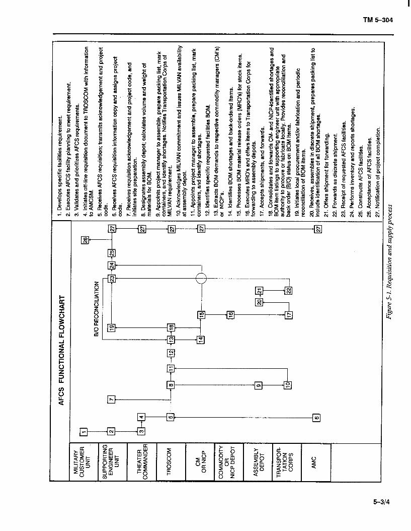
TM 5-304
TM S-304
APPENDM A
REFERENCES
A-l. Army Regulations
AR 415-16, Army Facilities Components System
AR 415-28, Department of the Army Facility Classes and Construction Categories
AR 570-2, Manpower Requirements Criteria
AR 710-1, Centralized Inventory Management of the Army Supply System
AR 725-50, Requisitioning, Receipt, and Issue System
A-2. Army Supply Catalog
Cl, Federal Supply Catalog
A-3. Field Manuals
FM 5-20, Camouflage
FM 101-10-2, Staff Officer’s Field Manual: Organizational, Technical, and Logistical Data Extracts of Nondivisional Tables of Organization and Equipment
A-4.Technical Manuals
TM 5-200, Camouflage Materials
TM 5-301-1, Army Facilities Components System--Planning (Temperate)
TM 5-301-2, Army Facilities Components System--Planning (Tropical)
TM 5-301-3, Army Facilities Components System--Planning (Frigid)
TM 5-301-4, Army Facilities Components System--Planning (Desert)
TM 5-302-1, Army Facilities Components System: Design
TM 5-302-2, Army Facilities Components System: Design
TM 5-302-3, Army Facilities Components System: Design
TM 5-302-4, Army Facilities Components System: Design
TM 5-302-5, Army Facilities Components System: Design
TM 5-303, Army Facilities Components System-Logistics Data and Bills of Materials
A-5. Huntsville Division Manual
CEHND 1105-l-1, TACAPS User Guide
A-112
TM 5-304
APPENDDt B
CAMOUFLAGE AND DISPERSAL
B-l. DEFENSIVE MEASURES a. Types. An installation’s abiity to survive are en-
hanced by two basically complementary defensive measures: active and passive. The best defense is built on a combination of those two measures, rather than depending on either category alone. However, each local situation must be assessed in order to determine the most effective mix of defense methods. For example, some locations might lack adequate land area for diiper- sal and will rely primarily on active defense measures, al- though in such cases, the threat may be so limited that active measures would not be required.
b. Active Measures. Active defenses complement pas- sive defenses by degrading the accuracy of weapons delivery and by limiting the effectiveness of enemy ground and air attack. Active defense can save resources by destroying some or all of the attacking force before an attack or by degrading the electronics of enemy weapons systems, rendering them ineffective. Use of antiaircraft units and ground security forces can significantly im- prove an installation’s survivability chances by limiting the strength and number of enemy attacks. The effective- ness of active defenses can be measured in terms of what is saved and the attrition rate of enemy forces.
c. Passive Measures. Passive defenses, such as camouflage and dispersal, complement active defenses by rendering the target difficult, if not impossible, to lo- cate and contain. Passive measures can force the enemy to use weapons and tactics that increase exposure to ac- tive combat units, antiaircraft, and perimeter security for- ces. The effectiveness of passive defenses can be measured in terms of targets saved or in terms of in- creased enemy effort. This chapter discusses how camouflage and dispersal can increase base security.
B-2. CAMOUFLAGE Camouflage is a concealment technique that includes hiding from view, making it difficult for the enemy to see clearly, arranging visual obstructions, and disguising ob- jects. When used correctly, camouflage can minimize a fmed installation’s vulnerability to enemy attack. Further- more, camouflage can be thought of as a counter-surveil- lance technique because it can mislead, confuse, or deny vital military information to enemy surveillance systems. Although a fmed installation usually cannot be totally
concealed, camouflage should at least conceal key ele- ments, forcing enemy intelligence to draw incorrect con- clusions about an installation’s operations.
a. Concealment Principles.
(1) Surveillance Technology. With advancements in the technology of surveillance systems, creating sophisti- cated sensors and weaponry that effectively camouflage a fned installation has become increasingly difficult; how- ever, certain concealment principles remain effective for enhancing the probability of an installation’s survival. Paragraphs (2) and (3) below briefly discuss the prin- ciples of concealment from both direct (people) and in- direct (photographic) observation.
(2) Recognition Factors. Since the eye is the most adaptive and responsive sensor, the objective of fmed in- stallation camouflage is to confuse and deceive the eye by countering the factors that the eye needs to identify objects. Paragraphs (a) through cf) below explain those recognition factors.
(a) Shape. All objects have a characteristic shape or outline that identifies them even before details can be seen. Camouflage can hide or disguise the shapes of standard recognizable objects.
(b) Shadow. An object’s characteristic shadow, or projection of its shape, may be more revealing than the object itself, especially if viewed from above. A shadow can be disguised by ground patterns, plantings, or false forms.
(c) Color. Color can aid an observer if there is a contrast between the object and its background. Light or bright colors tend to attract the eye, whereas darker or subdued colors tend to blend an object into the back- ground.
(d) Texture. Texture refers to an object’s ability to reflect, absorb, or diffuse light and can be defined as the relative roughness or smoothness of an object. For ex- ample, an airstrip, even though painted to match ad- jacent grassy areas, will appear much lighter in an aerial photograph because the textures differ.
(e) Position. An object can often be identified by its position in relation to its surroundings. For ex- ample, a long object on a railroad track is assumed to be
B-l
TM S-304
a train. Similar objects on a river floating parallel to its banks are assumed to be boats or barges.
cf) Movement. Movement does not necessarily identify an object, but will draw an observer’s attention. Vehicle tracks or a change in the position of a piece of equipment can be as noticeable as movement to trained observers.
(3) Concealment. Two principles of concealment-- siting and discipline--can diminish the negative effects of the recognition factors listed in (2) above.
(a) Siting. The purpose of siting is to select the most advantageous location for hiding an object. Often, a site’s natural slope and vegetation make elaborate camouflage unnecessary. Vital elements can be dis- persed in order to blur the installation’s tactical mission and increase its likelihood of survival during an attack.
(b) Discipline. For fixed-installation camouflage, all personnel must adhere to the conceal- ment principles used to protect the installation. For ex- ample, if a crane on a loading dock is carefully concealed, but empty oil drums, litter, and vehicle tracks can be seen around the area, then security has been com- promised. Observers could then deduce that the con- cealed object is critical without ever knowing exactly what it is.
b. Concealment Methoak
(1) Traditional Methods. Individuals charged with camouflaging an installation have traditionally used four methods of concealing structures and activities:
(a) Hiding. Obstruct a sensor’s field of view with natural terrain or foliage.
(b) Deceiving Mislead the enemy by manipula- tion, distortion, or falsification of evidence, inducing the enemy personnel to react in a manner prejudicial to their interest.
(c) Blending. Match an object’s reflectance char- acteristics to its background.
(d) Disguising. Give a sensor a false impression about an object.
(2) Expanded Methods. However, in order to carry out a successful camouflage operation, the four tradition- al methods must be expanded. Therefore, five more camouflage methods should also be considered:
(a) Mashing. Obstruct a sensor’s field of view with artificial cover such as a net.
B-2
(b) Blinding. Saturate a sensor, reducing its ef- fectiveness or damaging it permanently.
(c) Disrupting. Eliminate or modify. distinct ob- ject patterns.
(d) Distracting. Focus an enemy’s attention away from an object.
(e) Decoying. Provide an effective false object.
c. Runways and Taxiways. Although runways and taxiways cannot be protected from detection if they are subject to continued visual and photographic aerial ob- servation, they would be harder to recognize quickly at the usual bombing altitudes and speeds of modem aircraft if background color contrast were diminished and/or texturing materials added to tone down normal smooth and glaring surfaces.
d. Modular Lightweight Camouflage Screening System. AFCS does not include a camouflage facility for any structure. Instead, AFCS provides diagrams and charts that enable the user to develop adequate camouflage protection using the Army Modular Lightweight Camouflage Screening System. That system consists of a standard set of two nets (a hexagon and a diamond) and supporting equipment. Connecting the nets in various configurations produces the desired screen size. The Modular Lightweight Camouflage Screening System is not an AFCS design; therefore, it must be acquired separately, by NSN, through the supply system.
e. More Camouj7age Information. Further discussion about camouflage is beyond the scope of this manual. It should be noted, however, that successful camouflage re- quires the use of locally available materials as well as the proper siting and dispersal of structures with regard to existing vegetation and terrain. For more information, see FM 5-20 and TM 5-200.
B-3. DISPERSAL Dispersal is a cost-effective passive defense measure that depends on tactical and operational requirements, ter- rain limitations, and available engineer resources. Disper- sal eliminates the possibility of sympathetic explosions, complicates enemy attack, and causes the enemy to make multiple passes for each sortie in order to destroy the dis- persed aircraft or facilities effectively. Some drawbacks of ground dispersal of aircraft are increased communica- tions and security problems and possible new construc- tion for additional taxiways and hardstands; on the other hand, dispersal should cause little or no degradation to a unit’s operational capability. The relative merits of dis-
TM 5-304
persal in any given situation must be weighed against the threat analysis and any extra man-hours required.
a. Dispersal Principles.
(1) Separation Distances. Optimum dispersion oc- curs when the enemy must attack each parked aircraft, vehicle, or facility as a separate target.
(2) Site Choice. Protection against enemy observa- tion can be made much easier by choosing sites with a wide variety of ground features broken by irregular patches of trees and scrub growth.
(3) Use Natural Terrain. The dispersal (and camouflage) plan must take full advantage of terrain and its natural vegetation. The guiding principle should be to preserve the site’s existing pattern and character.
(4) AFCS Requirements and Dispersal. The area and facilities of AFCS installations are based on opera- tional requirements only; defensive measures beyond those for the anticipated minimal air threat in the com- munications zone are not emphasized. Therefore, the planner should consider increasing the number of linking facilities (roads, utilities, etc.) whenever significant dis- persal is required.
b. Dispersal Method.
(1) Personnel Facilities. Dispersal of personnel facilities depends on the limits of real estate, operational effectiveness, and installation security considerations.
(2) Power Generation. Installation power genera- tion should be located in two separate areas, with several individual generators at each location. Those generators should be positioned with adequate separation between each unit in order to provide maximum survivability. Overhead power transmission lines and their trans- formers should be routed and spaced in a manner that will preclude the loss of more than one circuit as a result of one attack. Backup generator units that supply power to critical facilities, with their associated high voltage dis- tribution centers and electrical distribution circuit cabling, should also be dispersed.
(3) Maintenance Facilities. Maintenance facilities should be dispersed so that separation is consistent with terrain features.
(4) Stored Munition. Accidental or deliberate detonation of stored munitions can be reduced by maxi- mum separation between explosives and other resources. Explosives should be dispersed into small compatible groups. Ammunition storage should not be located on an area’s periphery where it could be damaged easily by small arms fire.
(5) Key Operations. Splitting key storage or other operations into suboperations can provide effective dis- persion. For instance, the storage of one type of conven- tional ammunition could be split between the operating sections of an ammunition installation in order to mini- mize the impact of an enemy attack. Key elements of an installation should be located so that they are properly concealed and protected from ground attack by in- filtrators and guerrillas.
(6) Petroleum, Oil, Lubricant (POL). The sur- vivability of POL storage and dispensing systems can be increased by use of air transportable systems. Those sys- tems include portable storage tanks and dispensing sys- tems that may be dispersed and surrounded by earthen dikes. Fuel should not be stored on the periphery of an area where it could be damaged easily by small arms fire.
(7) Motor Vehicles. Motor vehicles should not be pooled. Parking motor vehicles under or beside trees or next to earthen embankments can provide dispersal as well as partial concealment.
(8) AircrafS.
(a) Parked Aircraft. Random dispersal of parked aircraft can increase their survivability during an attack, since sortie requirements of attacking aircraft in- crease from two to four times when aircraft parked at 50- foot separations are changed to irregular parking with minimum separations of 300 feet. An aircraft dispersal plan should take into consideration operational require- ments, maintenance, base security, existing parking areas, and the availability of real estate for additional aircraft parking.
(b) Runways and Tan’ways. A survivability measure for runways and taxiways is base selection. A runway of minimum length and width could be made use- less when hit with one bomb; however, portions of a larger runway could be used for emergency launch and recovery of aircraft after several hits.
(c) Air Traffic Control Facilities. Navigational aid and air traffic control facilities normally should be dispersed because operational considerations require that they be isolated from other facilities.
(d) Dispersal Layouts. Figures B-l through B-4 show proposed layouts and dispersal patterns that may meet a variety of tactical operations with minimum con- struction effort. Those layouts were developed as guidance for field commanders and units in TO’s and for use by planners at higher levels of command.
B-3
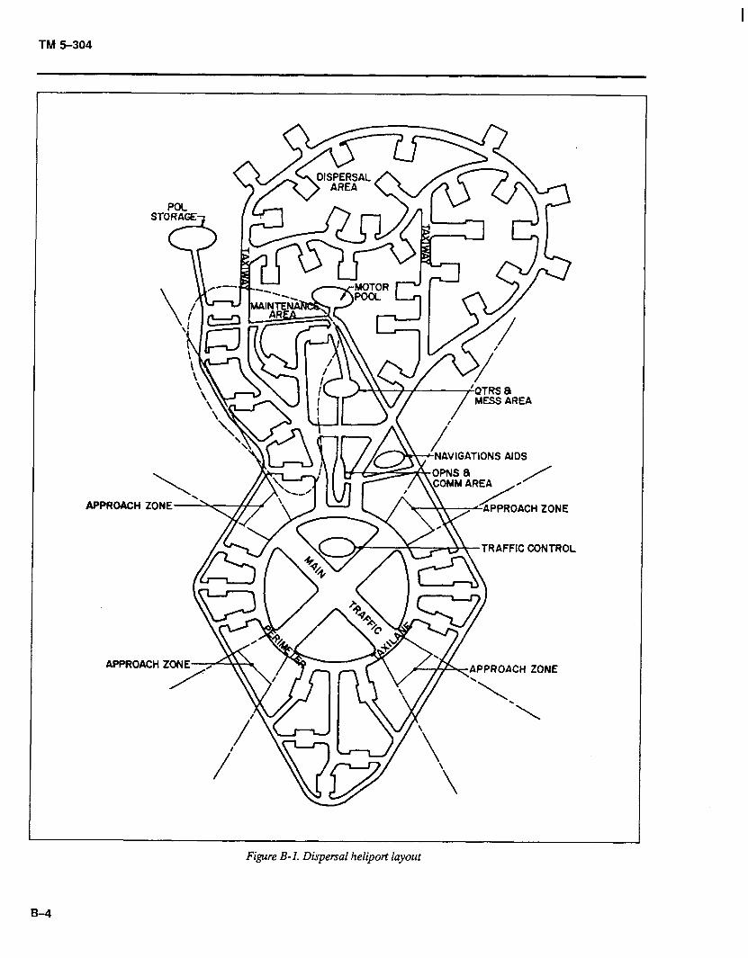
TM 5-304
\ APPROACH ZONE-
APPROACH
__---- - LA-/ -
.
r Y \\
. A \ - \ TRAFFIC CONTROL
\APPROACH ZONE
Figure B-l. Dispersal heliport layout
B-9
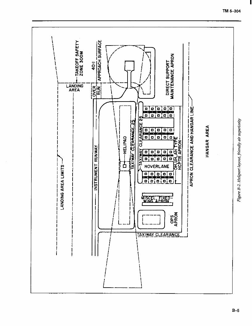
TM 5-304
I \ I I I I I
I I \ .--
i LANDING
AREA
B-5
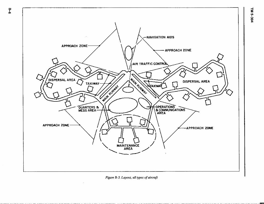
APPROACH ZONE APPROACHZONE
APPROACH ZONE APPROACH ZONE
Figure B-3. Layout, all types of aircraft
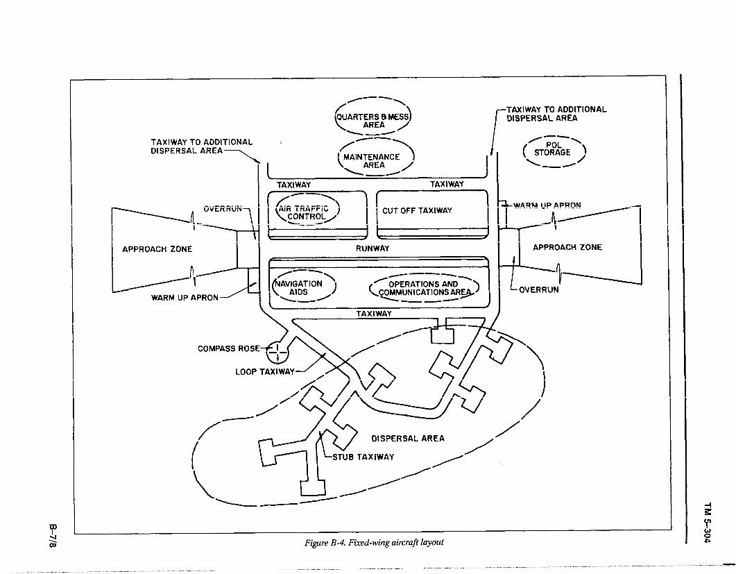
TAXIWAY TO ADDITIONAL DISPERSAL AREA
TAXIWAY TO ADDITIONAL DISPERSAL AREA
-- ’
( / POL
STORAGE 2 \ --
TAXIWAY
/ DISPERSAL AREA /
STUB TAXIWAY
Figure B-4. Fixed-wing aircraft layout
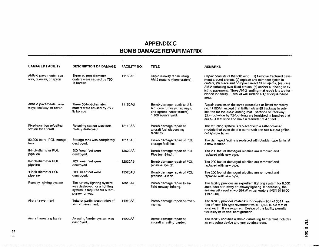
APPENDIX C BOMB DAMAGE REPAIR MATRIX
DAMAGED FACILITY DESCRIPTION OF DAMAGE
Airfield pavements: run- way, taxiway, or apron
Three 50-foot-diameter craters were caused by 750- lb bombs.
Airfield pavements: run- ways, taxiway, or apron
Three 50-foot-diameter craters were caused by 750- lb bombs.
Fixed-position refueling station for aircraft
Refueling station was com- pletely destroyed.
50,000-barrel POL storage tank
8inch-diameter POL pipeline
6inchdiameter POL pipeline
4-inch-diameter POL pipeline
Runway lighting system
Aircraft revetment
Aircraft arresting barrier
Storage tank was completely destroyed.
200 linear feet were destroyed.
200 linear feet were destroyed.
200 linear feet were destroyed.
The runway lighting system was destroyed, or a lighting system is required for a tem- porary runway.
Total or partial destruction of aircraft revetment.
Arresting barrier system was destroyed.
,
FACILITY NO.
11150AF
11150AG
12llOAB
12110AE
12520AA
12520AB
12520AC
13610AA
1491oAA
1492oAA
TITLE
Rapid runway repair using AM-2 matting (three craters).
Bomb damage repair to U.S. Air Force runways, taxiways, and aprons (three craters) 1,260 square yard.
Bomb damage repair of aircraft fuel-dispensing facilities.
Bomb damage repair of POL storage facilities.
Bomb damage repair of POL Pipeline, 8-inch.
Bomb damage repair of POL pipeline, g-inch.
Bomb damage repair of POL pipeline, 4-inch.
Bomb damage repair to air- field runway lighting.
Bomb damage repair of revet- ments.
Bomb damage repair of aircraft arresting barrier.
REMARKS
Repair consists of the following: (1) Remove fractured pave- ment around craters, (2) replace and compact ejecta in craters, (3) place and compact select fill on ejecta. (4) place AM-2 surfacing over filled craters, (5) anchor surfacing’to ex- isting pavement. Three AM-2 landing mat repair kits are fur- nished in facility. Each kit will surface a 4,185-square-foot area.
Repair consists of the same procedure as listed for facility no. 1115OAF, except that British class 60 trackway is sub- stituted for the AM-2 landing mat. Sections of trackway 52.4-foot-wide by 72-foot-long are furnished in bundles that are 52.4 feet wide and have a diameter of 4.1 feet.
The refueling system is replaced with a self-contained module that consists of a pump unit and two 50,000-gallon collapsible tanks.
The damaged facility is replaced with bladder-type tanks at a new location.
The 200 feet of damaged pipeline are removed and replaced with new pipe.
The 200 feet of damaged pipeline are removed and replaced with new pipe.
The 200 feet of damaged pipeline are removed and replaced with new pipe.
The facility provides an expedient lighting system for 8,000 linear feet of runway or taxiway lighting. If necessary, the system will require two 30-kW ac generators (NSN 6115-00- 118-1240).
The facility provides materials for construction of 384 linear feet of steel bin-type revetment walls. 1,920 cubic feet of local earth fill are required. Design of the facility permits flexibility of its final configuration.
The facility contains a BAK-12 arresting barrier that includes an engaging device and energy absorbers.
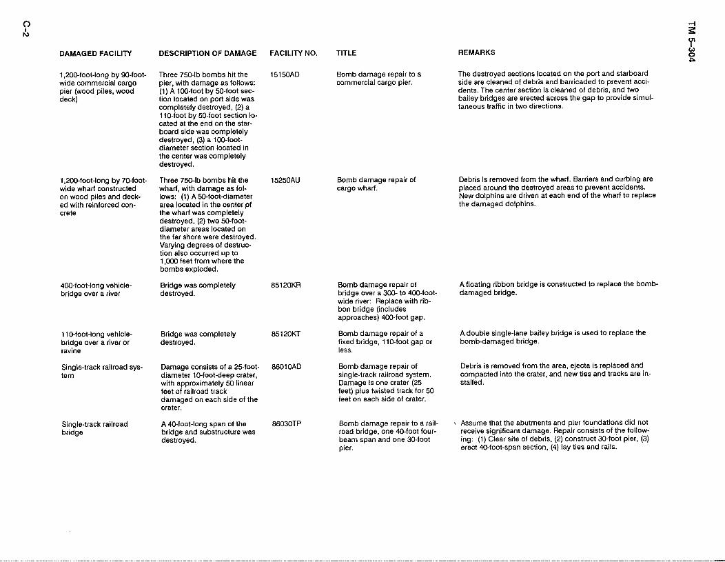
DAMAGED FACILITY DESCRIPTION OF DAMAGE FACILITY NO. TITLE
1,200-foot-long by 90-foot- Three 750-lb bombs hit the 15150AD Bomb damage repair to a wide commercial cargo pier, with damage as follows: commercial cargo pier. pier (wood piles, wood (1) A loO-foot by 50-foot sec- deck) tion located on port side was
completely destroyed, (2) a 1 lo-foot by 50-foot section lo- cated at the end on the star- board side was completely destroyed, (3) a lOO-foot- diameter section located in the center was completely destroyed.
1,200-foot-long by 70-foot- Three 750-lb bombs hit the 15250AU Bomb damage repair of wide wharf constructed wharf, with damage as fol- cargo wharf. on wood piles and deck- lows: (1) A 50-footdiameter ed with reinforced con- area located in the center pf Crete the wharf was completely
destroyed, (2) two 50-foot- diameter areas located on the far shore were destroyed. Varying degrees of destruc- tion also occurred up to 1,000 feet from where the bombs exploded.
400-foot-long vehicle- Bridge was completely bridge over a river destroyed.
85120KR Bomb damage repair of bridge over a 300-to 400-foot- wide river: Replace with rib- bon bridge (includes approaches) 400-foot gap.
1 IO-foot-long vehicle- bridge over a river or ravine
Bridge was completely destroyed.
85120KT
Single-track railroad sys- tern
Damage consists of a 25-foot- 8601 OAD diameter lo-footdeep crater, with approximately 50 linear feet of railroad track damaged on each side of the crater.
Single-track railroad bridge
A 40-foot-long span of the bridge and substructure was destroyed.
86030TP
I REMARKS
The destroyed sections located on the port and starboard side are cleaned of debris and barricaded to prevent acci- dents. The center section is cleaned of debris, and two bailey bridges are erected across the gap to provide simul- taneous traffic in two directions.
Debris is removed from the wharf. Barriers and curbing are placed around the destroyed areas to prevent accidents. New dolphins are driven at each end of the wharf to replace the damaged dolphins.
A floating ribbon bridge is constructed to replace the bomb- damaged bridge.
Bomb damage repair of a fixed bridge, 1 lo-foot gap or less.
A double single-lane bailey bridge is used to replace the bomb-damaged bridge.
Bomb damage repair of single-track railroad system. Damage is one crater (25 feet) plus twisted track for 50 feet on each side of crater.
Debris is removed from the area, ejecta is replaced and compacted into the crater, and new ties and tracks are in- stalled.
Bomb damage repair to a rail- road bridge, one 40-foot four- beam span and one 30-foot pier.
) Assume that the abutments and pier foundations did not receive significant damage. Repair consists of the follow- ing: (1) Clear site of debris, (2) construct do-foot pier, (3) erect 40-foot-span section, (4) lay ties and rails.
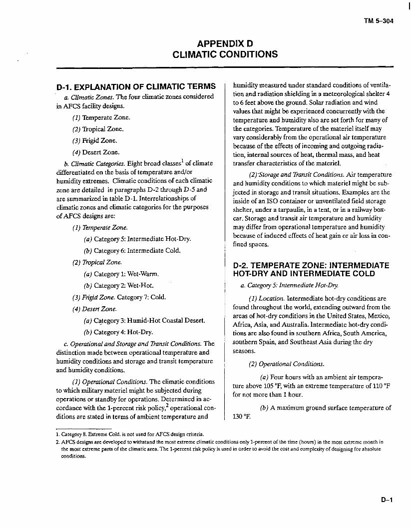
TM 5-304
APPENDIX D CLIMATIC CONDITIONS
D-l. EXPLANATION OF CLIMATIC TERMS a. Climatic Zones. The four climatic zones considered
in AFCS facility designs.
(I) Temperate Zone.
(2) Tropical Zone.
(3) Frigid Zone.
(4) Desert Zone.
b. Climatic Categories. Eight broad classes’ of climate differentiated on the basis of temperature and/or humidity extremes. Climatic conditions of each climatic zone are detailed in paragraphs D-2 through D-5 and are summarized in table D-l. Interrelationships of climatic zones and climatic categories for the purposes of AFCS designs are:
(1) Temperate Zone.
humidity measured under standard conditions of ventila- tion and radiation shielding in a meteorological shelter 4 to 6 feet above the ground. Solar radiation and wind values that might be experienced concurrently with the temperature and humidity also are set forth for many of the categories. Temperature of the materiel itself may vary considerably from the operational air temperature because of the effects of incoming and outgoing radia- tion, internal sources of heat, thermal mass, and heat transfer characteristics of the materiel.
(a) Category 5: Intermediate Hot-Dry.
(b) Category 6: Intermediate Cold.
(2) Tropical Zone.
(a) Category 1: Wet-Warm.
(b) Category 2: Wet-Hot.
(3) Frigid Zone. Category 7: Cold.
(4) Desert Zone.
(2)Storage and Transit Conditions. Air temperature and humidity conditions to which materiel might be sub- jected in storage and transit situations. Examples are the inside of an IS0 container or unventilated field storage shelter, under a tarpaulin, in a tent, or in a railway box- car. Storage and transit air temperature and humidity may differ from operational temperature and humidity because of induced effects of heat gain or air loss in con- fined spaces.
D-2. TEMPERATE ZONE: INTERMEDIATE HOT-DRY AND INTERMEDIATE COLD
a. Category 5: Intermediate Hot-Dty.
(a) Category 3: Humid-Hot Coastal Desert.
(b) Category 4: Hot-Dry.
c. Operational and Storage and Transit Conditions. The distinction made between operational temperature and humidity conditions and storage and transit temperature and humidity conditions.
(1) Location. Intermediate hot-dry conditions are found throughout the world, extending outward from the areas of hot-dry conditions in the United States, Mexico, Africa, Asia, and Australia. Intermediate hot-dry condi- tions are also found in southern Africa, South America, southern Spain, and Southeast Asia during the dry seasons.
(1) Operational Conditions. The climatic conditions to which military materiel might be subjected during operations or standby for operations. Determined in ac- cordance with the l-percent risk policy,2 operational con- ditions are stated in terms of ambient temperature and
(2) Operational Conditions.
(a) Four hours with an ambient air tempera- ture above 105 “F, with an extreme temperature of 110 “F for not more than 1 hour.
(b) A maximum ground surface temperature of 130 “F.
1. Category 8, Extreme Cold, is not used for AFCS design criteria. 2. AFc!j designs are developed to withstand the most extreme climatic conditions only l-percent of the time (hours) in the most extreme month in
the most extreme parts of the climatic area. The l-percent risk policy is used in order to avoid the cost and complexity of designing for absolute conditions.
D-l
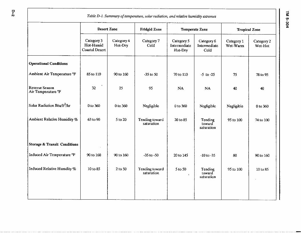
0 k Table D-l. Summary of temperahue, solar radiation, and relative humid@ extremes
Operational Conditions
Desert Zone
Category 3 Category 4 Hot-Humid Hot-Dry
Coastal Desert
Fridgid Zone
Category 7 Cold
Temperate Zone
Category 5 Category 6 Intermediate Intermediate
Hot-Dry Cold
Tropical Zone
Category 1 Category 2 Wet-Warm Wet-Hot
Ambient Air Temperature “F
Reverse Season Air Temperature “F
85 to 110 9Oto160 -35 to 50 70 to 110 -5 to -25 75 78 to 95
’ 32 25 95 NA NA 40 40
Solar Radiation Btu/fi2/hr 0 to 360
Ambient Relative Humidity % 63to90
0 to 360
5 to 20
Negligible
Tending toward saturation
oto360
20 to 85
Negligible
Tending toward
saturation
Negligible 0 to 360
95 to 100 74 to 100
Storage & Transit Conditions
Induced Air Temperature “F 9Oto160 9Oto160 -35 to -50 20 to 145 -10 to -35 80 9Oto160
Induced Relative Humdity % 10 to 85 2 to 50 Tending toward saturation
5 to 50 Tending 95 to 100 10 to 85 , toward
saturation
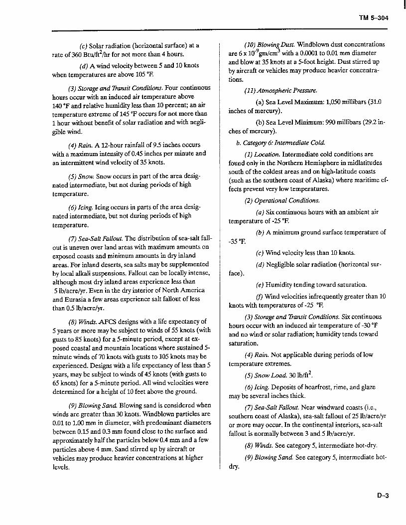
I TM 5-304
(c) Solar radiation (horizontal surface) at a rate of 360 Btu/ft2/hr for not more than 4 hours.
(d) A wind velocity between 5 and 10 knots when temperatures are above 105 “F.
(3) Storage and Transit Conditions. Four continuous hours occur with an induced air temperature above 140 “F and relative humidity less than 10 percent; an air temperature extreme of 145 “F occurs for not more than 1 hour without benefit of solar radiation and with negli- gible wind.
(4) Rain. A 1Zhour rainfall of 9.5 inches occurs with a maximum intensity of 0.45 inches per minute and an intermittent wind velocity of 35 knots.
(5) Snow. Snow occurs in part of the area desig- nated intermediate, but not during periods of high temperature.
(6) Icing. Icing occurs in parts of the area desig- nated intermediate, but not during periods of high temperature.
(7) Sea-Salt Fallout. The distribution of sea-salt fall- out is uneven over land areas with maximum amounts on exposed coasts and minimum amounts in dry inland areas. For inland deserts, sea salts may be supplemented by local alkali suspensions. Fallout can be locally intense, although most dry inland areas experience less than 5 lb/acre&. Even in the dry interior of North America and Eurasia a few areas experience salt fallout of less than 0.5 lb/acre&r.
(8) Winds. AFCS designs with a life expectancy of 5 years or more may be subject to winds of 55 knots (with gusts to 85 knots) for a 5-minute period, except at ex- posed coastal and mountain locations where sustained 5- minute winds of 70 knots with gusts to 105 knots may be experienced. Designs with a life expectancy of less than 5 years, may be subject to winds of 45 knots (with gusts to 65 knots) for a 5-minute period. All wind velocities were determined for a height of 10 feet above the ground.
(9) Blowing Sand. Blowing sand is considered when winds are greater than 30 knots. Wmdblown particles are 0.01 to 1.00 mm in diameter, with predominant diameters between 0.15 and 0.3 mm found close to the surface and approximately half the particles below 0.4 mm and a few particles above 4 mm. Sand stirred up by aircraft or vehicles may produce heavier concentrations at higher levels.
(10) Blowing Dust. Wmdblown dust concentrations are 6 x 10⁻⁹gm/cm3 with a 0.0001 to 0.01 mm diameter and blow at 35 knots at a 5-foot height. Dust stirred up by aircraft or vehicles may produce heavier concentra- tions.
(11) Atmospheric Pressure.
(a) Sea Level Maximum: 1,050 millibars (31.0 inches of mercury).
(b) Sea Level Minimum: 990 millibars (29.2 in- ches of mercury).
b. Category 6: Intemediate Cold.
(1) Location. Intermediate cold conditions are found only in the Northern Hemisphere in midlatitudes south of the coldest areas and on high-latitude coasts (such as the southern coast of Alaska) where maritime ef- fects prevent very low temperatures.
(2) Operarional Conditions.
(a) Six continuous hours with an ambient air temperature of -25 “E
(b) A minimum ground surface temperature of -35 “F.
face).
(c) Wind velocity less than 10 knots.
(d) Negligible solar radiation (horizontal sur-
(e) Humidity tending toward saturation.
cf) Wind velocities infrequently greater than 10 knots with temperatures of -25 “F.
(3) Storage and Transit Conditions. Six continuous hours occur with an induced air temperature of -30 “F and no wind or solar radiation; humidity tends toward saturation.
(4) Rain. Not applicable during periods of low temperature extremes.
(5) Snow Load. 30 lb/ft2.
(6) Icing. Deposits of hoarfrost, rime, and glaze may be several inches thick.
(7) Sea-Salt Fallout. Near windward coasts (i.e., southern coast of Alaska), sea-salt fallout of 25 lb/acre&r or more may occur. In the continental interiors, sea-salt fallout is normally between 3 and 5 lb/acre&r.
(8) Winds. See category 5, intermediate hot-dry.
(9) Blowing Sand. See category 5, intermediate hot- dry*
D-3
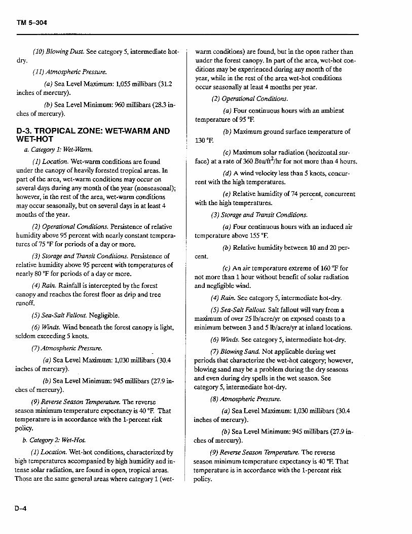
TM 5-304
(10) Blowing Dust. See category 5, intermediate hot- dry-
(11) Atmospheric Pressure.
(a) Sea Level Maximum: 1,055 millibars (31.2 inches of mercury).
(b) Sea Level Minimum: 960 millibars (28.3 in- ches of mercury).
D-3. TROPICAL ZONE: WET-WARM AND WET-HOT
a. Category 1: Wet-Warm.
(1) Location. Wet-warm conditions are found under the canopy of heavily forested tropical areas. In part of the area, wet-warm conditions may occur on several days during any month of the year (nonseasonal); however, in the rest of the area, wet-warm conditions may occur seasonally, but on several days in at least 4 months of the year.
(2) Operational Conditions. Persistence of relative humidity above 95 percent with nearly constant tempera- tures of 75 “F for periods of a day or more.
(3) Storage and Transit Conditions. Persistence of relative humidity above 95 percent with temperatures of nearly 80 “F for periods of a day or more.
(4) Rain. Rainfall is intercepted by the forest canopy and reaches the forest floor as drip and tree runoff.
(5) Sea-Salt Fallout. Negligible.
(6) winds. Wind beneath the forest canopy is light, seldom exceeding 5 knots.
(7) Atmospheric Pressure.
(a) Sea Level Maximum: 1,030 millibars (30.4 inches of mercury).
(b) Sea Level Minimum: 945 millibars (27.9 in- ches of mercury).
(9) Reverse Season Temperature. The reverse season minimum temperature expectancy is 40 “E That temperature is in accordance with the l-percent risk policy.
b. Catego y 2: Wet-Hot.
(1) Location. Wet-hot conditions, characterized by high temperatures accompanied by high humidity and in- tense solar radiation, are found in open, tropical areas. Those are the same general areas where category 1 (wet-
D-4
warm conditions) are found, but in the open rather than under the forest canopy. In part of the area, wet-hot con- ditions may be experienced during any month of the year, while in the rest of the area wet-hot conditions occur seasonally at least 4 months per year.
(2) Operational Conditions.
(a) Four continuous hours with an ambient temperature of 95 “F.
(b) Maximum ground surface temperature of 130 “F.
(c) Maximum solar radiation (horizontal sur- face) at a rate of 360 Btu/ft2/hr for not more than 4 hours.
(d) A wind velocity less than 5 knots, concur- rent with the high temperatures.
(e) Relative humidity of 74 percent, concurrent with the high temperatures.
(3) Storage and Transit Conditions.
(a) Four continuous hours with an induced air temperature above 155 “E
(b) Relative humidity between 10 and 20 per- cent.
(c) An air temperature extreme of 160 “F for not more than 1 hour without benefit of solar radiation and negligible wind.
(4) Rain. See category 5, intermediate hot-dry.
(5) Sea-Salt Fallout. Salt fallout will vary from a maximum of over 25 lb/acre/yr on exposed coasts to a minimum between 3 and 5 lb/acre&r at inland locations.
(6) Winds. See category 5, intermediate hot-dry.
(7) Blowing Sand. Not applicable during wet periods that characterize the wet-hot category; however, blowing sand may be a problem during the dry seasons and even during dry spells in the wet season. See category 5, intermediate hot-dry.
(8) Atmospheric Pressure.
(a) Sea Level Maximum: 1,030 millibars (30.4 inches of mercury).
(b) Sea Level Minimum: 945 millibars (27.9 in- ches of mercury).
(9) Reverse Season Temperature. The reverse season minimum temperature expectancy is 40 “E That temperature is in accordance with the l-percent risk policy.
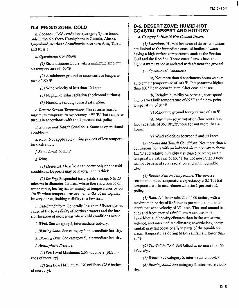
TM 5-304
D-4. FRIGID ZONE: COLD a. Location. Cold conditions (category 7) are found
only in the Northern Hemisphere in Canada, Alaska, Greenland, northern Scandinavia, northern Asia, Tibet, and Russia.
b. Operational Conditions.
(1) Six continuous hours with a minimum ambient air temperature of -50 “F.
(2) A minimum ground or snow surface tempera- ture of -50 “E
(3) Wmd velocity of less than 10 knots.
(4) Negligible solar radiation (horizontal surface).
(5) Humidity tending toward saturation.
c. Reverse Season Temperature. The reverse season maximum temperature expectancy is 95 “F. That tempera- ture is in accordance with the l-percent risk policy.
d. Storage and Transit Conditions. Same as operational conditions.
e. Rain. Not applicable during periods of low tempera- ture extremes.
f: Snow Load. 60 lb/ft2.
g. IcLtg.
(1) Hoarjrost. Hoarfrost can occur only under cold conditions. Deposits may be several inches thick.
(2) Ice Fog. Suspended ice crystals average 5 to 20 microns in diameter. In areas where there is a source of water vapor, icefog occurs mainly at temperatures below -20 “F; when temperatures are below -35 “F, ice fog may be very dense, limiting visibility to a few feet.
h. Sea-Salt Fallout. Generally, less than 3 lb/acre&r be- cause of the low salinity of northern waters and the inte- rior location of most areas where cold conditions occur.
i. Wind. See category 5, intermediate hot-dry.
j. Blowing Sand. See category 5, intermediate hot-dry.
k. Blowing Dust. See category 5, intermediate hot-dry.
1. Atmospheric Pressure.
(1) Sea Level Maximum: 1,060 millibars (31.3 in- ches of mercury).
(2) Sea Level Minimum: 970 millibars (28.6 inches of mercury).
D-5. DESERT ZONE: HUMID-HOT COASTAL DESERT AND HOT-DRY
a. Catego y 3: Humid-Hot Coastal Desert.
(1) Locations. Humid-hot coastal desert conditions are limited to the immediate coast of bodies of water having a high surface temperature, such as the Persian Gulf and the Red Sea. Those coastal areas have the highest water vapor associated with air near the ground.
(2) Operational Conditions.
(a) Not more than 4 continuous hours with an ambient air temperature of 100 “E Temperatures higher than 100 “F can occur in humid-hot coastal desert.
(b) Relative humidity 64 percent, correspond- ing to a wet bulb temperature of 89 “F and a dew point temperature of 86 “E
(c) Maximum ground temperature of 130 “E
(d) Maximum solar radiation (horizontal sur- face) at a rate of 360 Btu/ft2/hour for not more than 4 hours.
(e) Wmd velocities between 5 and 10 knots.
(3) Storage and Transit Conditions. Not more than 4 continuous hours with an induced air temperature above 155 “F and relative humidity less than 5 percent; an air temperature extreme of 160 “F for not more than 1 hour without benefit of solar radiation and with negligible wind.
(4) Reverse Season Temperature. The reverse season minimum temperature expectancy is 32 “F. That temperature is in accordance with the l-percent risk policy.
(5) Rain. A l-hour rainfall of 4.00 inches, with a maximum intensity of 0.45 inches per minute and an in- termittent wind velocity of 35 knots. The total annual in- ches and frequency of rainfall are much less in the humid-hot and hot-dry climates than in the wet-warm, wet-hot, and intermediate climates; nevertheless, heavy rainfall may fall occasionally in parts of the humid-hot areas. Temperatures during heavy rainfall are lower than 80 “E
(6) Sea-Salt Fallout. Salt fallout is no more than 25 lb/acre/y-r.
(7) Winds. See category 5, intermediate hot-dry.
(8) Blowing Sand. See category 5, intermediate hot- dry.
D-5
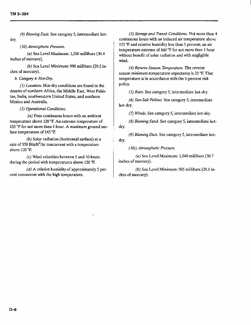
TM 5-304
(9) Blowing Dust. See category 5, intermediate hot- dry.
(10) Atmospheric Pressure.
(a) Sea Level Maximum: 1,030 millibars (30.4 inches of mercury).
(b) Sea Level Minimum: 990 millibars (29.2 in- ches of mercury).
b. Category 4: Hot-D y.
(1) Location. Hot-dry conditions are found in the deserts of northern Africa, the Middle East, West Pakis- tan, India, southwestern United States, and northern Mexico and Australia.
(2) Operational Conditions.
(a) Four continuous hours with an ambient temperature above 120 “E An extreme temperature of 125 “F for not more than 1 hour. A maximum ground sur- face temperature of 145 “F.
(b) Solar radiation (horizontal surface) at a rate of 350 Btu/ft2/hr concurrent with a temperature above 120 “F.
(c) Wmd velocities between 5 and 10 knots during the period with temperatures above 120 “F.
(d) A relative humidity of approximately 5 per- cent concurrent with the high temperature.
(3) Storage and Ttansit Conditions. Not more than 4 continuous hours with an induced air temperature above 155 “F and relative humidity less than 5 percent; an air temperature extreme of 160 “F for not more than 1 hour without benefit of solar radiation and with negligible wind.
(4) Reverse Season Temperature. The reverse season minimum temperature expectancy is 25 “F. That temperature is in accordance with the l-percent risk policy.
(5) Rain. See category 5, intermediate hot-dry.
(6) Sea-Salt Fallout. See category 5, intermediate hot-dry.
(7) winds. See category 5, intermediate hot-dry.
(8) Blowing Sand. See category 5, intermediate hot- dry.
(9) Blowing Dust. See category 5, intermediate hot- dry.
(10)) Atmosjheric Pressure.
(a) Sea Level Maximum: 1,040 millibars (30.7 inches of mercury).
(b) Sea Level Minimum: 985 millibars (29.1 in- ches of mercury).
D-6
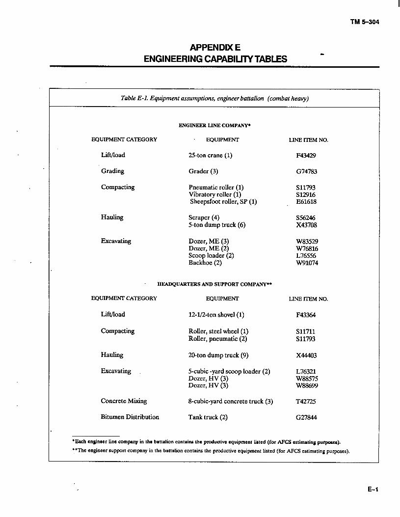
TM tc304
APPENDDt E ENGINEERING CAPABILITYTABLES -
Table E-l. Equipment assumptions, engineer battalion (combat heavy)
ENGINEER LINE COMPANY*
EQUIPMENT CATEGORY . EQUIPMENT
Lit/load 25ton crane (1)
Grading Grader (3)
Compacting Pneumatic roller (1) Vibratory roller (1) Sheepsfoot roller, SP (1)
Hauling Scraper (4) 5-ton dump truck (6)
Excavating Dozer, ME (3) Dozer, ME (2) Scoop loader (2) Backhoe (2)
HEADQUARTERS AND SUPPORT COMPANY-
EQUIPMENT CATEGORY EQUIPMENT
Lift/load 12-l&ton shovel (1)
Compacting Roller, steel wheel (1) Roller, pneumatic (2)
Hauling 20-ton dump truck (9)
Excavating 5-cubic -yard scoop loader (2) Dozer, HV (3) Dozer, HV (3)
Concrete Mixing 8-cubic-yard concrete truck (3)
Bitumen Distribution Tank truck (2)
LINE ITEM NO.
F43429
G74783
s11793 S12916 E61618
s56246 x43708
W83529 W76816 L76556 w91074
LINE ITEM NO.
F43364
s11711 s11793
x44403
L76321 w88575 W88699
T42725
G27844
*Each cnginacr line company in thr battalion contains the productiva oquipment listed (for AFCS estimating purposes).
lithe engineer support company in the battalion contains the productive equipment listed (for AFCS estimating purposes).
, E-l
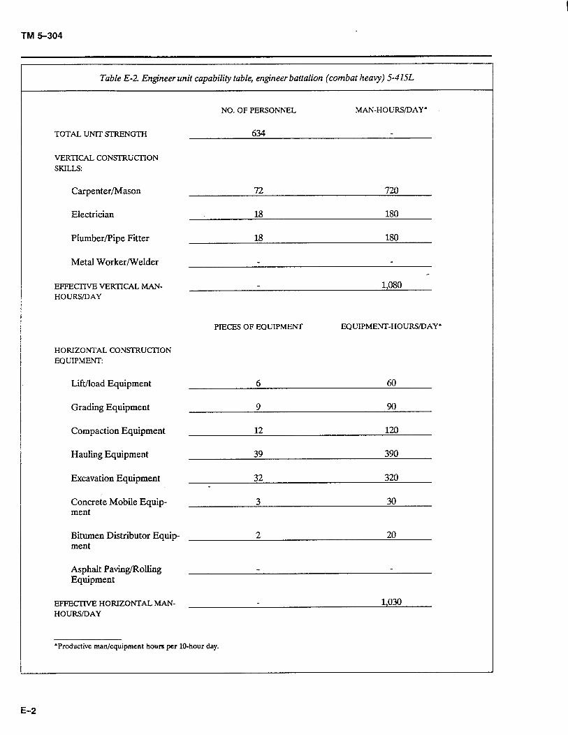
TM 5-304
Table E-2. Engineer unit capability table, engineer battalion (combat heavy) S-4lSL
TOTAL UNIT SIRENGTH
VERTICAL CONSIRUCTION SKILLS:
NO. OF PERSONNEL
634
MAN-HOURS/DAY l
Carpenter/Mason
Electrician
Plumber/Pipe Fitter
Metal Worker/Welder
72 720
18 180
18 180
EFFECTIVE VERTICAL MAN- 1,080 HOURS/DAY
PIECES OF EQUIPMENT EQUIPMENT-HOURS/DAY’
HORIZONTAL CONSTRUCTION EQUIPMENT:
Lift/load Equipment
Grading Equipment
Compaction Equipment
Hauling Equipment
Excavation Equipment
Concrete Mobile Equip- ment
6 60
9 90
12 120
39 390
32 320
3 30
Bitumen Distributor Equip- ment
2 20
Asphalt Paving/Rolling Equipment
EFFECTWE HORIZONTAL MAN- 1,030 HOURS/DAY
*Productive man/equipment hours per lo-hour day.
E-2
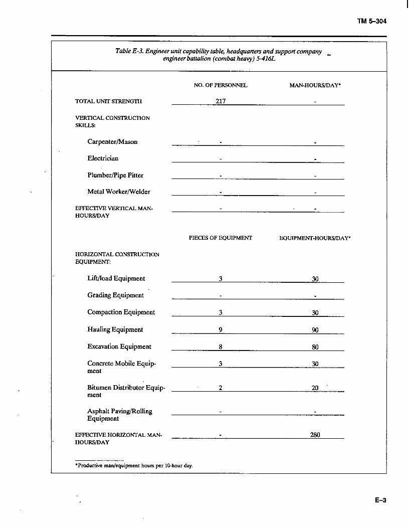
TM 5-304
Table E-3. Engineer unit capability table, headquarters and support company engineer battalion (combat heavy) 9416L
~
NO. OF PERSONNEL MAN-HOURS/DAY*
TOTAL UNIT SI-RENGTH 217
VERTICAL CONSIRUCTION SKILLS:
Carpenter/Mason
Electrician
Plumber/Pipe Fitter
Metal Worker/Welder
EFFECTIVE! VERTICAL MAN- HOURS/DAY
PIECES OF EQUIPMENT EQUIPMENT-HOURS/DAY*
HORIZONTAL CONSI-RUCI-ION EQUIPMENT:
Lift/load Equipment 3 30
Grading Equipment
Compaction Equipment 3 30
Hauling Equipment 9 90
Excavation Equipment
Concrete Mobile Equip- ment
3 30
Bitumen Distributor Equip- ment
2 20 ’
Asphalt Paving/Rolling Equipment
EFFECTIVE HORIZONTAL MAN- 280 HOURS/DAY
*Productive man/equipment hours per IO-hour day.
E-3
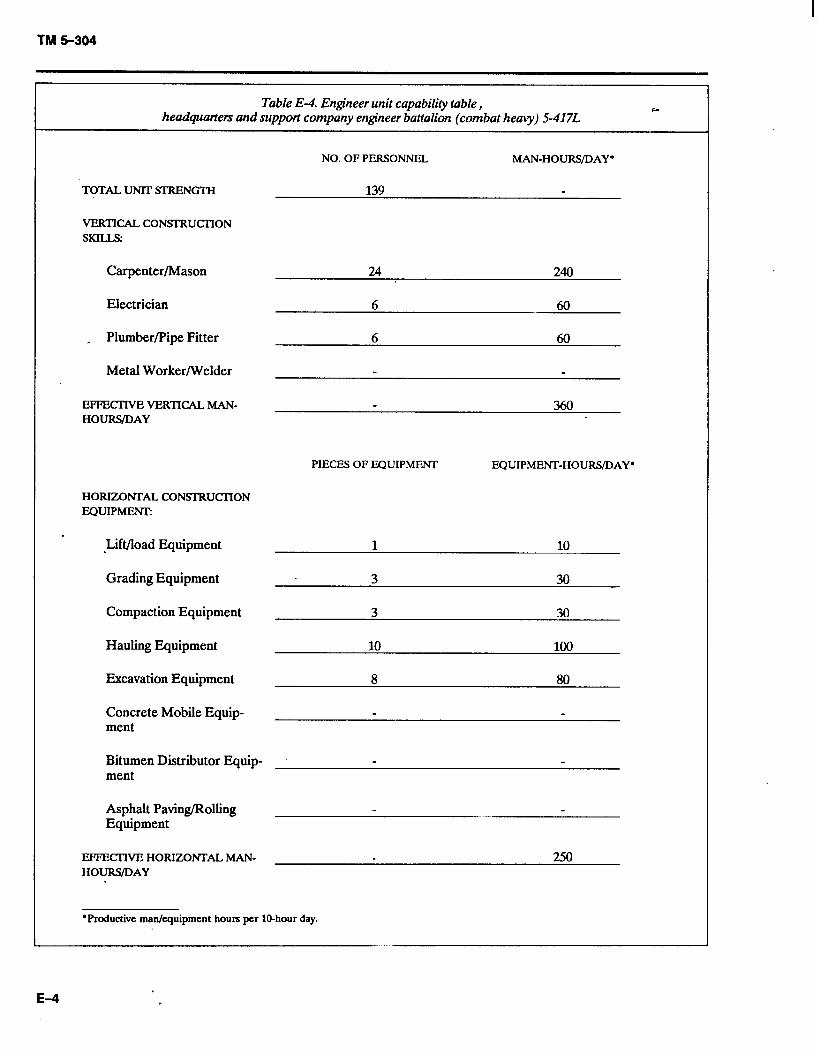
TM $304
Table E-4. Engineer unit capability table, headquarters and support company engineer battalion (combat heavy) 5-4171:
NO. OF PERSONNEL MAN-HOURS/DAY*
TOTAL UNIT SI’RENGTH 139
VERTICAL CON!5-I-‘RUCXION SKILL3
Carpenter/Mason 24 240
Electrician 6 60
_ Plumber/Pipe Fitter 6 60
Metal Worker/Welder
EFTEKlWEVERTICALMAN- 3f.30 HOURS/DAY
PIECES OF EQUIPMENT EQUIPMENT-HOURS/DAY*
HORIZONTAL CONSI-RUCI-ION EQUIPMENT:
I
-Lift/load Equipment
Grading Equipment
Compaction Equipment 3 30
Hauling Equipment 10 100
Excavation Equipment 8 80
Concrete Mobile Equip- ment
Bitumen Distributor Equip- ment
Asphalt Paving/Rolling Equipment
EF’FECIWE! HORIZONTAL MAN- 250 HOURS/DAY
*Productive man/equipment hours per lo-hour day.
E-4
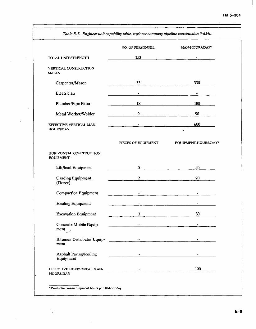
TM 5-304
Table E-5. Engineer unit capability table, engineer company pipeline construction 5-&L
NO. OF PERSONNEL MAN-HOURS/DAY l
TOTAL UNlT SIRENGTH 153 -
VERTICAL CON!XRUCl-ION SKILLS:
Carpenter/Mason
Electrician
33 330
Plumber/Pipe Fitter
Metal Worker/Welder
EFFECTIVE VERTICAL MAN- HOURS/DAY
18 180
9 90
fm
HORIZONTAL CONWRUCI-ION EQUIPMENT:
PIECES OF EQUIPMENT EQUIPMENT-HOURS/DAY*
Lift/load Equipment
Grading Equipment (Dozer)
Compaction Equipment
Hauling Equipment
Excavation Equipment
Concrete Mobile Equip- ment , -I’
Bitumen Distribute; Equip- ment
-
3 30
-
-
Asphalt Paving/Rolling Equipment
EFFECI’IVE HORIZONTAL MAN- 100 HOURS/DAY
fproductive man/equipment hours per IO-hour day.
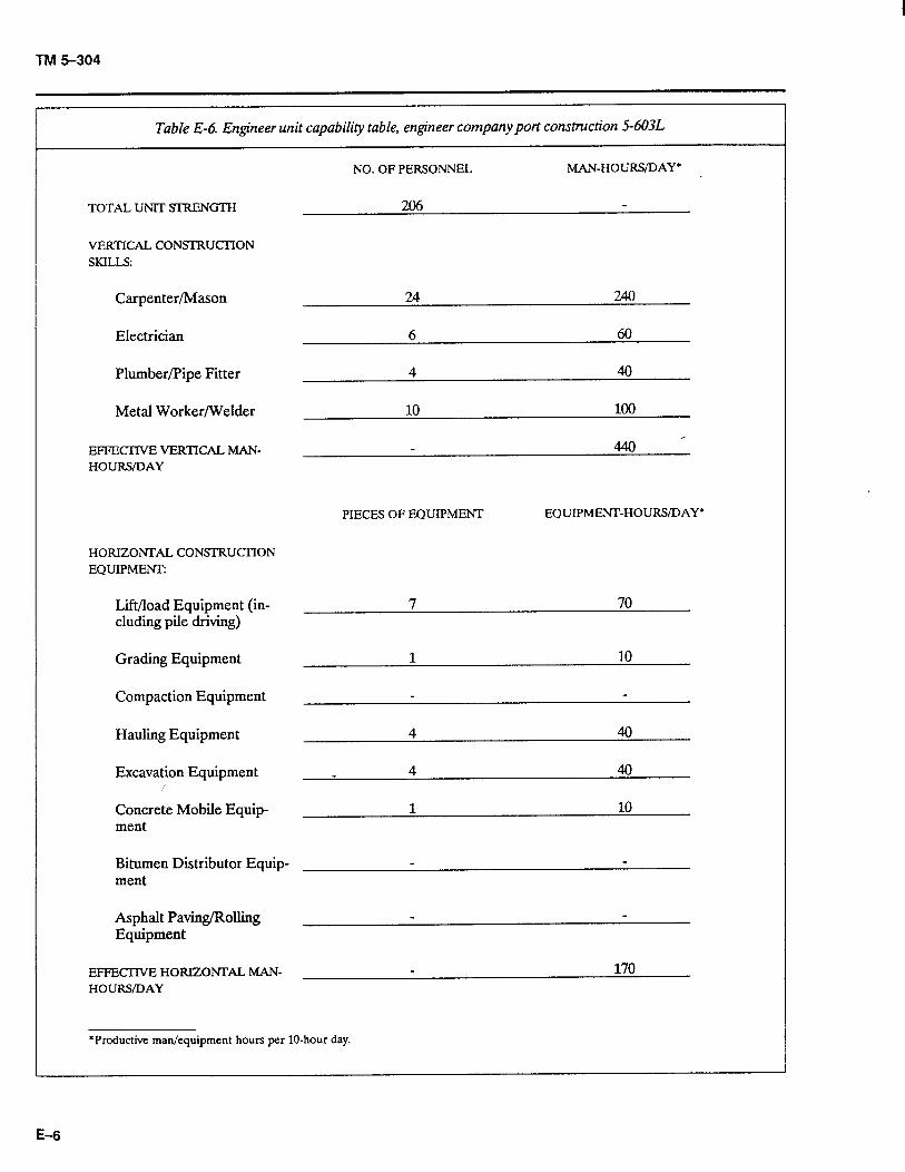
TM 5-304
Table E-6. Engineer unit capabili& table, engineer company port construction 9603L
NO. OF PERSONNEL MAN-HOURS/DAY*
TOTAL UNIT SJXENGTH
VERTICAL CONSI-RUCI-ION SKILLS:
Carpenter/Mason
Electrician
Plumber/Pipe Fitter
Metal Worker/Welder
EFFEClWE VERTICAL MAN- HOURS/DAY
HORIZONTAL CONSl-RUCI-ION EQUIPMENT:
Lift/load Equipment (in- cluding pile driving)
Grading Equipment
Compaction Equipment
Hauling Equipment
Excavation Equipment
Concrete Mobile Equip- ment
Bitumen Distributor Equip- ment
Asphalt Paving/Rolling Equipment
EFFECTIVE HORIZONTAL MAN- HOURS/DAY
10 100
440 -
PIECES OF EQUIPMENT EQUIPMEm-HOURS/DAY*
7 70
1 10
A 40
1 10
170
*Productive man/equipment hours per lo-hour day.
E-6
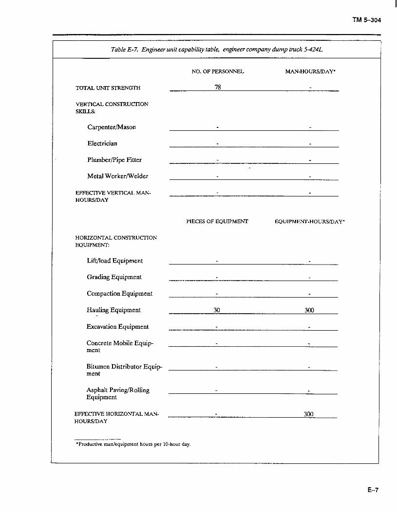
TM 5-304
Table E-7. Engineer unit capability table, engineer company dump truck S-424L
NO. OF PERSONNEL MAN-HOURS/DAY *
TOTAL UNIT SI-RENGTH
VERTICAL CONSTRUCI-ION SKILLS
Carpenter/Mason
Electrician
Plumber/Pipe Fitter
Metal Worker/Welder
EFFEClWE VERTICAL MAN- HOURS/DAY
PIECES OF EQUIPMENT EQUIPMENT-HOURS/DAY*
HORIZONTAL CONSTRUCTION EQUIPMEm
Lift/load Equipment
Grading Equipment
Compaction Equipment
Hauling Equipment
Excavation Equipment
Concrete Mobile Equip- ment
30 300
Bitumen Distributor Equip- ment
Asphalt Paving/Rolling Equipment
EFFECIWE HORIZONTAL MAN- 300 HOURS/DAY
*Productive man/equipment hours per IO-hour day.
E-7
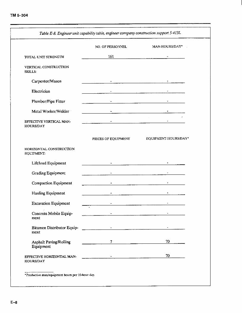
TM 5-304
Table E-8. Engineer unit capability table, engineer company construction support S-413L
TOTAL UNIT SI-RENGTI-I
VERTICAL CON!XRUCIlON SKILLS
Carpenter/Mason
Electrician
Plumber/Pipe Fitter
Metal Worker/Welder
EFFECIWE VERTICAL MAN- HOURS/DAY
NO. OF PERSONNEL MAN-HOURS/DAY*
PIECE-S OF EQUIPMENT EQUIPMENT-HOURS/DAY l
HORIZONTAL CONSTRUCI’ION EQUIPMEm
Lift/load Equipment
Grading Equipment
Compaction Equipment
Hauling Equipment
Excavation Equipment
Concrete Mobile Equip- ment
Bitumen Distributor Equip- ment
Asphalt Paving/Rolling Equipment
7 70
EFFECTIVE HORIZONI’AL MAN- 70 HOURS/DAY
*Productive man/equipment hours per IO-hour day.
E-8
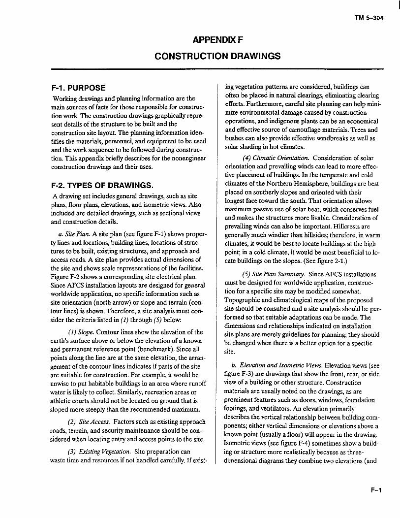
I TM 5-304
APPENDK F
CONSTRUCTION DRAWINGS
F-l. PURPOSE Working drawings and planning information are the main sources of facts for those responsible for construc- tion work. The construction drawings graphically repre- sent details of the structure to be built and the construction site layout. The planning information iden- tifies the materials, personnel, and equipment to be used and the work sequence to be followed during construc- tion. This appendix briefly describes for the nonengineer construction drawings and their uses.
F-2. TYPES OF DRAWINGS. A drawing set includes general drawings, such as site plans, floor plans, elevations, and isometric views. Also included are detailed drawings, such as sectional views and construction details.
a. Site Plan. A site plan (see figure F-l) shows proper- ty lines and locations, building lines, locations of struc- tures to be built, existing structures, and approach and access roads. A site plan provides actual dimensions of the site and shows scale representations of the facilities. Figure F-2 shows a corresponding site electrical plan. Since AFCS installation layouts are designed for general worldwide application, no specific information such as site orientation (north arrow) or slope and terrain (con- tour lines) is shown. Therefore, a site analysis must con- sider the criteria-listed in (1) through (5) below:
(1) Slope. Contour lines show the elevation of the earth’s surface above or below the elevation of a known and permanent reference point (benchmark). Since all points along the line are at the same elevation, the arran- gement of the contour lines indicates if parts of the site are suitable for construction. For example, it would be unwise to put habitable buildings in an area where runoff water is likely to collect. Similarly, recreation areas or athletic courts should not be located on ground that is sloped more steeply than the recommended maximum.
(2) Site Access. Factors such as existing approach roads, terrain, and security maintenance should be con- sidered when locating entry and access points to the site.
(3) Existing Vegetation. Site preparation can waste time and resources if not handled carefully. If exist-
ing vegetation patterns are considered, buildiigs can often be placed in natural clearings, eliminating clearing efforts. Furthermore, careful site planning cau help mini- mize environmental damage caused by construction operations, and indigenous plants can be an economical and effective source of camouflage materials. Trees and bushes can also provide effective windbreaks as well as solar shading in hot climates.
(4) Climatic Orientation. Consideration of solar orientation and prevailing winds can lead to more effec- tive placement of buildiigs. In the temperate and cold climates of the Northern Hemisphere, buildings are best placed on southerly slopes and oriented with their longest face toward the south. That orientation allows maximum passive use of solar heat, which conserves fuel and makes the structures more livable. Consideration of prevailing winds can also be important. Hillcrests are generally much windier than hillsides; therefore, in warm climates, it would be best to locate buildings at the high point; in a cold climate, it would be most beneficial to lo- cate buildings on the slopes. (See figure 2-l.)
(5) Site Plan Summary. Since AFCS installations must be designed for worldwide application, construc- tion for a specific site may be modified somewhat. Topographic and climatological maps of the proposed site should be consulted and a site analysis should be per- formed so that suitable adaptations can be made. The dimensions and relationships indicated on installation site plans are merely guidelines for planning; they should be changed when there is a better option for a specific site.
b. Elevation and Isometric Views. Elevation views (see figure F-3) are drawings that show the front, rear, or side view of a building or other structure. Construction materials are usually noted on the drawings, as are prominent features such as doors, windows, foundation footings, and ventilators. An elevation primarily describes the vertical relationship between building com- ponents; either vertical dimensions or elevations above a known point (usually a floor) will appear in the drawing. Isometric views (see figure F-4) sometimes show a build- ing or structure more realistically because as three- dimensional diagrams they combine two elevations (and
F-l
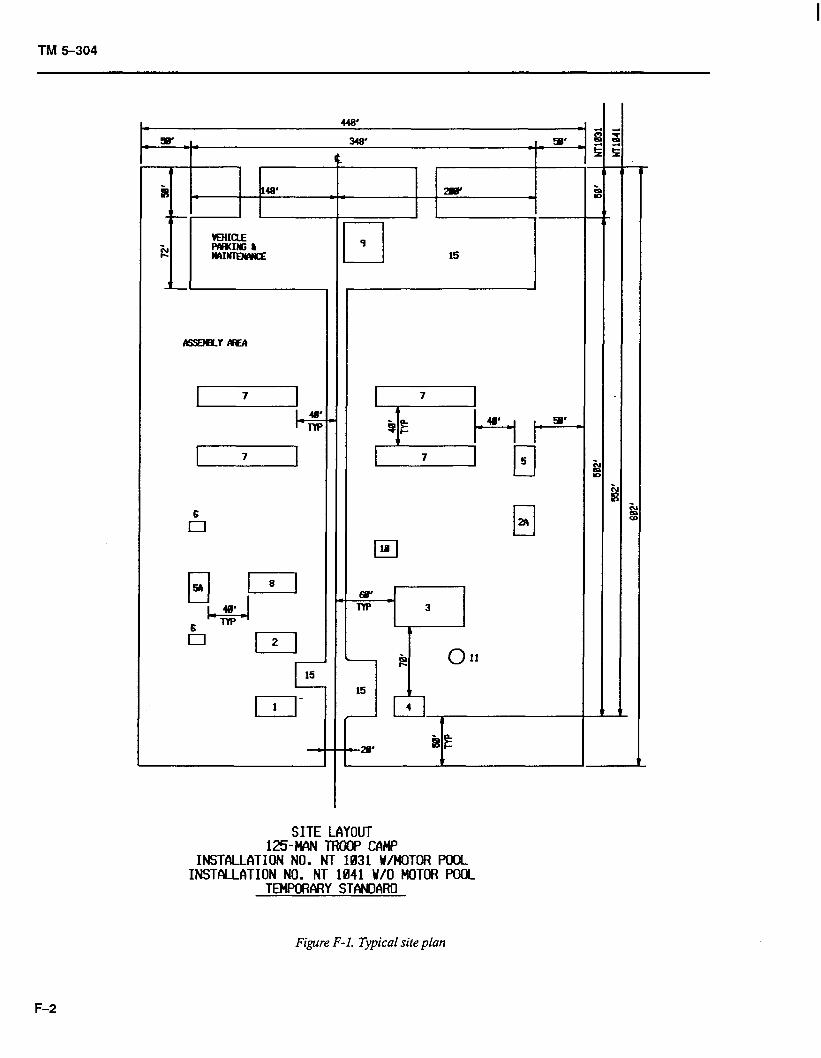
TM 5-304
c 15
El 1 -
-
SITE LAYOUT 125-w TROW cfw
INSTALLATION NO. NT 1831 U/MOTOR F’OOL INSTALLATION NO. NT 1841 V/O MOTOR POOL
TENF’ORCIRY STANDARO
Figure F-l. Typical site plan
F-2
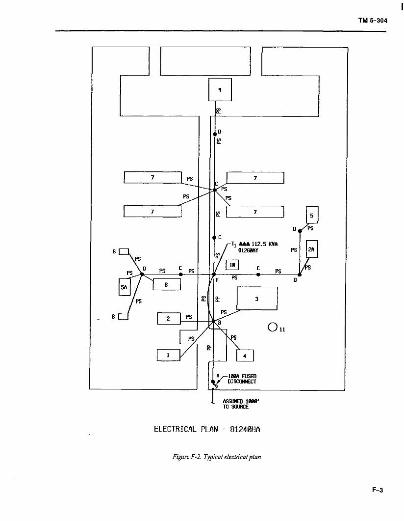
TM 5-304
6
:
ps
& 1
k 3
/= R
8
lY3
0
4
11
ELECTRICAL PLAN - 81240HA
Figure F-2. Typical electrical plan
F-3
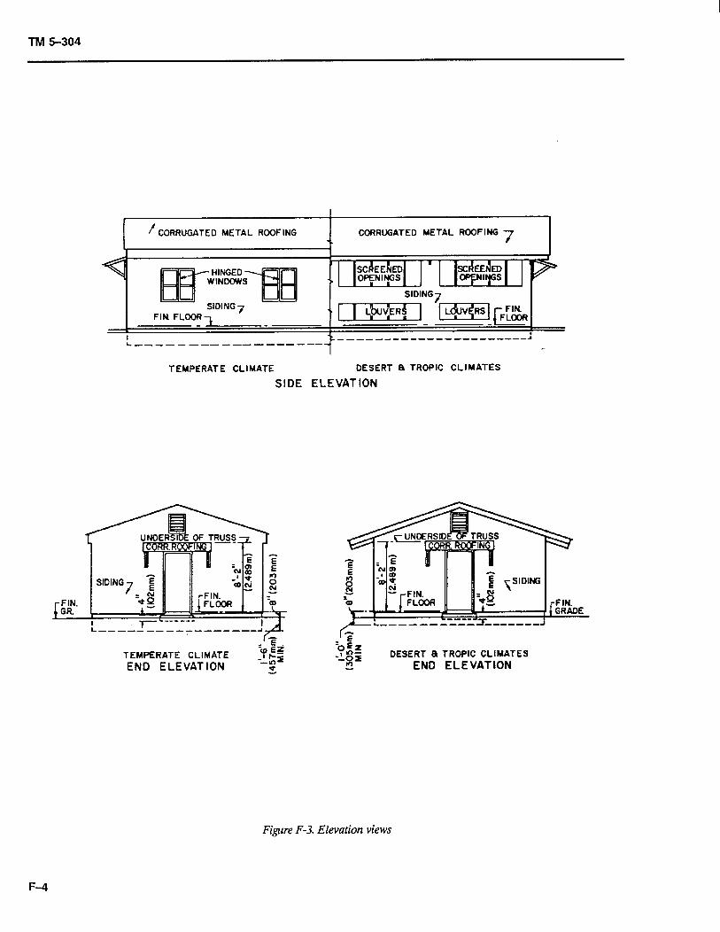
TM 5-304
I FIN. GR.
CORRUGATED METAL ROOFING CORRUGATED METAL ROOFING
TEMPERATE CLIMATE DESERT 8 TROPIC CLIMATES
SIDE ELEVATION
------m--B
r-z TEMPERATE CLIMATE
‘(0 Eg -::z
END ELEVATION s DESERT a TROPIC CLIMATES
EN0 ELEVATION
Figure F-3. Elevation views
F-4
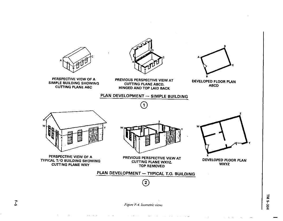
C
@ ’ C
A
. 6
PERSPECTfVE VIEW OF A SIMPLE BUILDING SHOWING
PREVIOUS PERSPECTIVE VIEW AT
CUTTING PLANE ABC CUI-IING PLANE ABCD,
HINGED AND TOP LAID BACK
D
A
8
C
fi
DEVELOPED FLOOR PLAN ABC0
PIAN DEVELOPMENT - SIMPLE BUILDING
0 1
PERSPECTIVE VIEW OF A TYPICAL T/O BUILDING SHOWING
CUlTlNG PLANE WXY
PREVIOUS PERSPECTIVE VIEW AT CUTTING PLANE WXY2I.
TOP REMOVED
PIAN DEVELOPMENT - WPICAL T.O. EWILDI~G
0 2
Figure F-4. Isometric views
DE:VELOPED FLOOR PLAN WXYZ
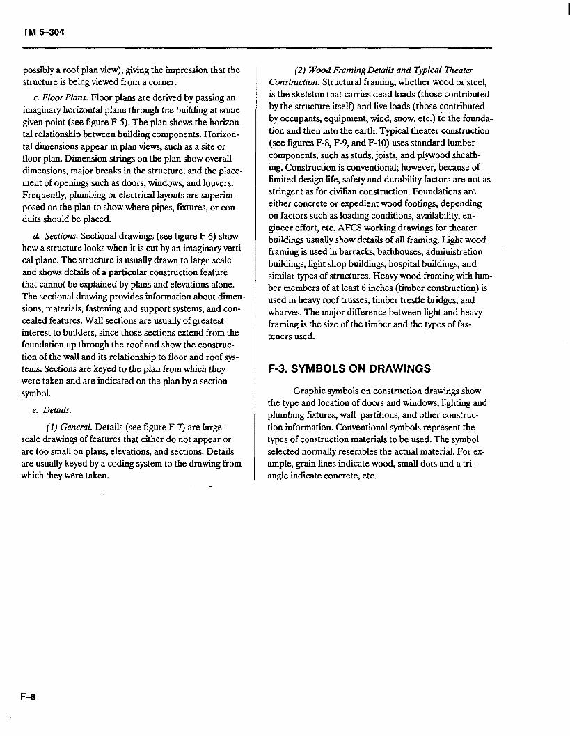
TM 5-304
possibly a roof plan view), giving the impression that the structure is being viewed from a corner.
c. Floor Plans. Floor plans are derived by passing an imaginary horizontal plane through the building at some given point (see figure F-5). The plan shows the horizon- tal relationship between building components. Horizon- tal dimensions appear in plan views, such as a site or floor plan. Dimension strings on the plan show overall dimensions, major breaks in the structure, and the place- ment of openings such as doors, windows, and louvers. Frequently, plumbing or electrical layouts are superim- posed on the plan to show where pipes, ftiures, or con- duits should be placed.
d. Sections. Sectional drawings (see figure F-6) show how a structure looks when it is cut by an imaginary verti- cal plane. The structure is usually drawn to large scale and shows details of a particular construction feature that cannot be explained by plans and elevations alone. The sectional drawing provides information about dimen- sions, materials, fastening and support systems, and con- cealed features. Wail sections are usually of greatest interest to builders, since those sections extend from the foundation up through the roof and show the construc- tion of the wall and its relationship to floor and roof sys- tems. Sections are keyed to the plan from which they were taken and are indicated on the plan by a section symbol.
e. Details.
(I) General. Details (see figure F-7) are large- scale drawings of features that either do not appear or are too small on plans, elevations, and sections. Details are usually keyed by a coding system to the drawing from which they were taken.
(2) Wood Framing Details and Trpical Theater Construction. Structural framing, whether wood or steel, is the skeleton that carries dead loads (those contributed by the structure itself) and live loads (those contributed by occupants, equipment, wind, snow, etc.) to the founda- tion and then into the earth. Typical theater construction (see figures F-8, F-9, and F-10) uses standard lumber components, such as studs, joists, and plywood sheath- ing. Construction is conventional, however, because of limited design life, safety and durability factors are not as stringent as for civilian construction. Foundations are either concrete or expedient wood footings, depending on factors such as loading conditions, availability, en- gineer effort, etc. AFCS working drawings for theater buildings usually show details of all framing. Light wood framing is used in barracks, bathhouses, administration buildings, light shop buildings, hospital buildings, and similar types of structures. Heavy wood framing with lum- ber members of at least 6 inches (timber construction) is used in heavy roof trusses, timber trestle bridges, and wharves. The major difference between light and heavy framing is the size of the timber and the types of fas- teners used.
F-3. SYMBOLS ON DRAWINGS
Graphic symbols on construction drawings show the type and location of doors and windows, lighting and plumbing ftiures, wall partitions, and other construc- tion information. Conventional symbols represent the types of construction materials to be used. The symbol selected normally resembles the actual material. For ex- ample, grain lines indicate wood, small dots and a tri- angle indicate concrete, etc.
F-6
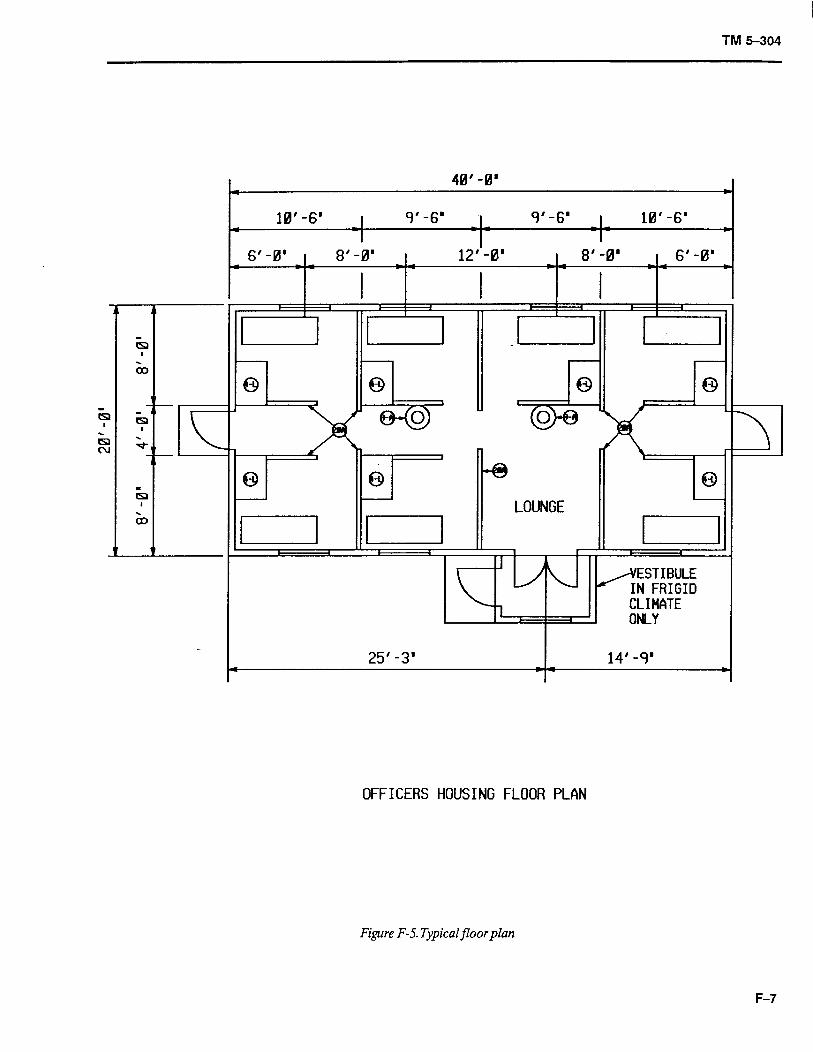
TM 5-304
- K
. 40’ -0’
10’ -6’ I 9’ -6’ I- 9’ -6’ I- 10’ -6’ . .
6’ -0’
- I
8’ -0’ 12”-0’ 8’ -0’ 6’ -0’ . CI .
I I I
Iu P=- 8
/@ LOUNGE [ ‘3
/ ESTIBULE
IN FRIGID CLIMATE ONLY
14’ -9’
OFFICERS HOUSING FLOOR PLAN
Figure F-5. Typical floor plan
F-7
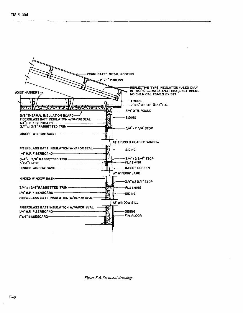
TM 5-304
RRUGATEO METAL ROOFING
REFLECTIVE TYPE INSULATION IN TROPIC CLIMATE AND THEN, NO CHEMICAL FUMES EXIST)
2”~ 6” JOISTS a 24”O.C.
HINGED WINDOW SASH M 11
TRUSS 8 HEAD OF WINDOW
FIBERGLASS BATT IN
l/4”H.P. FIBERBOARD
3/4”x I 5/a” 3”~ 3” HINGE
HINGED WINDOW SASH
HINGED WINDOW SASH
3/4”x 2 3/4” STOP
SECT SCREEN
3/4”x I 5/8”RABBETTED TRIM
l/4” H.P. FIBERBOA
FiBERGLASS BATT
-FLASHING
FIBERGLASS BATT IN 1/4”H.F! FIBERBOARD
I” x 6” BASEBOARD
(USED ONLY ONLY WHERE
Figure F-6. Sectional drawings
F-8
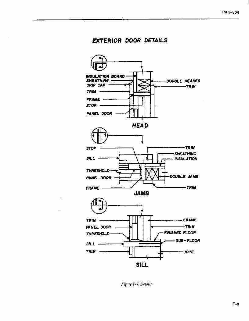
TM 5-304
EXTERIOR DOOR OfTAILS
PANEL DOOR
HEAD
PANQ DOOR DOUBLE JAMB
JAMB
Figure F-7. Details
F-9
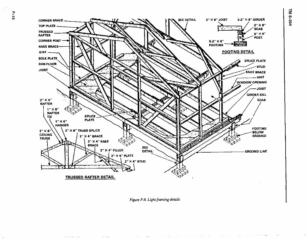
CORNER BRACE SEE DETAIL 2” X 6” JOIST 3-Z” X 6” GIRDER
TOP PLATE - -1 2” x 6” ’ SCAB
6” X 6”
CORNER POST
KNEE BRACE
SOLE PLATE
SUB-FLOOR
JOIST \ w
\ TIE - S PLATE
X 6” TRUSS SPLICE
I +s’. v .a* rnPAr.lE L -7 DMYL
2” X 4” KNEE
\ FOOTING DETAIL
SPLICE PLATE
2” X 4” STUD
v- FOOTING BELOW
TRUSSED RAFTER DETAIL ,
Figure F-8. Light framing details
GROUND LINE
2 H P
-
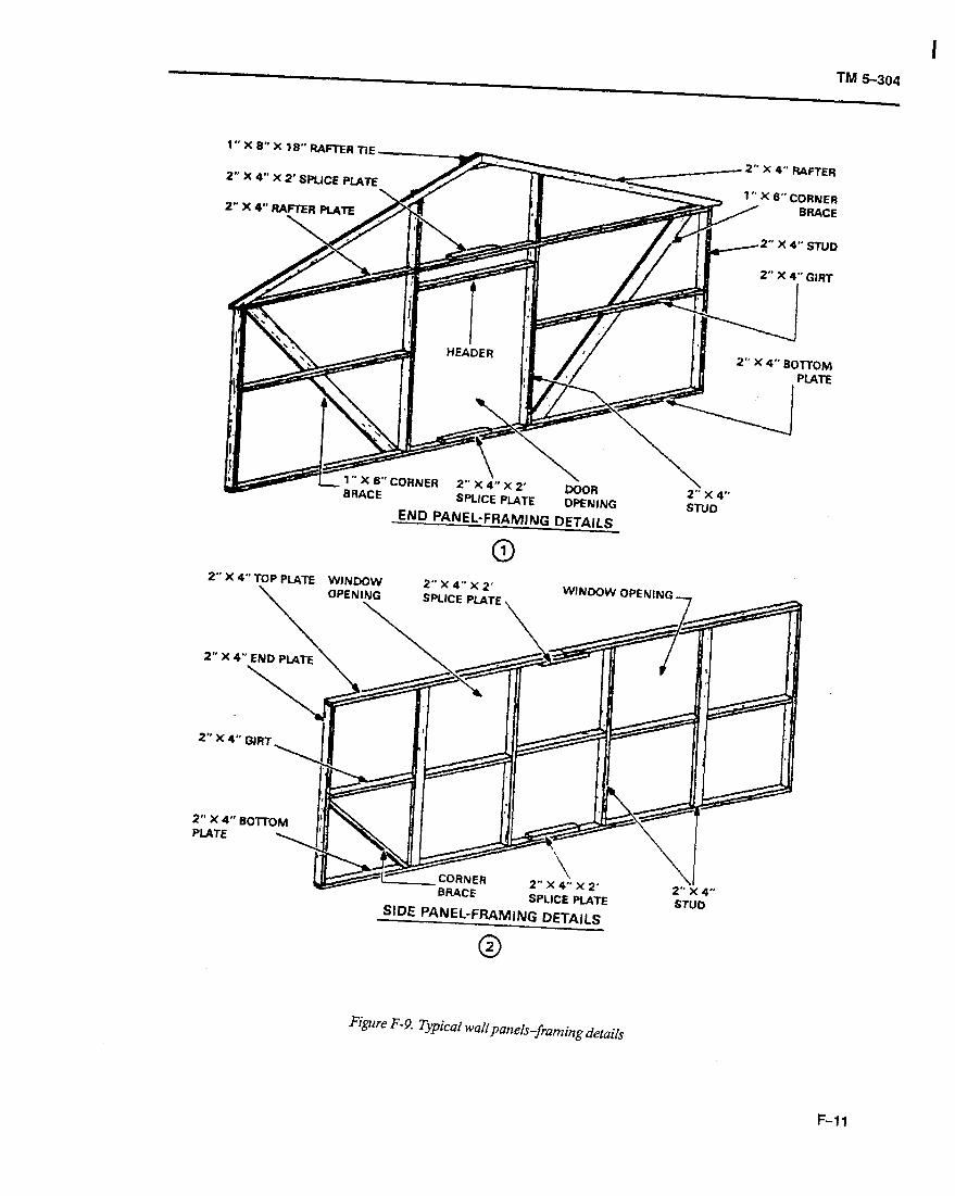
I TM 5-304
1.’ X 8” X 18” RAFER TIE
2” X 4” X 2’ SPLICE PLATE
- L’ L BRACE
x 4’. x 2’ SPLICE PLATE
DOOR OPENING
2.:x 4”
END PANEL-FRAMING DETAILS STUD
0 1 z- X 4” TOP PLATE WINDOW ” ” ’
\ OPEN]\ zpllc4E F$TE, W’ND0W OPENING -
2” X 4” END PLATE \ \
SIDE PANEL-FRAMING DETAILS
2” A 4. son-OM PLATE 4 \
Figue F-9. Typical waN panels--framing details
F-11
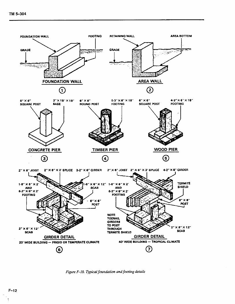
TM 5-304
FOUNDATION WALL FODTING RETAINING WALL AREA EOnTOM
FOUNDATION WALL
0 1
AREA WALL
0 2
6” X 6” 3-x 16”X16” 6” X 6” 5-3” X 6” X 18” 6” X 6” 4-3” X 6” X 18”
SQUARE POST BASE ROUND POST FOOTING SQUARE POST FOOTING
-. .:.,.... “:.
@
CONCRETE PIER TIMBER PIER WOOD PIER
0 3
2” X 6” JOIST 2” X 6” X 2’SWCE 3-2” X 6” GIRDER 2” X 6” JOIST 2” X 6” X 2’ SPLICE 4-2” X 8” GIRDER
FOOTING I
1-6” X 6” X 1
6-2” X 8” X 2’
GIRDER DETAIL GIRDER DETAIL 2O’WlDE BUILDING i FRIGID OR TEMPERATE CLIMATE 40’ WIDE BUILDING - TROPICAL CLIMATE
0 4 0 5
1.6” X 6” X 2’
6-2” x 8” x 2’
NOTE: hi TOENAIL GIRDERS TO POST THROUGH TERMITE SHIELD Y
TERMITE SHIfLD
8”
0 6 0 7
Figure F-10. Typical foundation and footing details
F-12
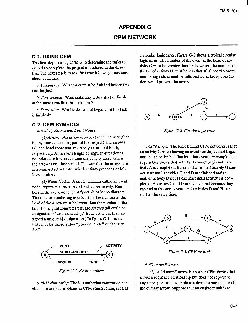
I TM 5-304
APPENDDt G
CPM NETWORK
G-l. USING CPM The first step in using CPM is to determine the tasks re- quired to complete the project as outlined in the direc- tive. The next step is to ask the three following questions about each task:
a. Precedence. What tasks must be finished before this task begins?
b. Concurrence. What tasks may either start or finish at the same time that this task does?
c. Succession. What tasks cannot begin until this task is finished?
G-2. CPM SYMBOLS a. Activity Arrows and Event Nodes.
(I) Arrows. An arrow represents each activity (that is, any time-consuming part of the project); the arrow’s tail and head represent an activity’s start and finish, respectively. An arrow’s length or angular direction is not related to how much time the activity takes; that is, the arrow is not time scaled. The way that the arrows are interconnected indicates which activity precedes or fol- lows another.
(2) Event Nodes. A circle, which is called an event node, represents the start or finish of an activity. Num- bers in the event node identify activities in the diagram. The rule for numbering events is that the number at the head of the arrow must be larger than the number at the tail. (For digital computer use, the arrow’s tail could be designated 9” and its head “j.” Each activity is then as- signed a unique i-j designation.) In figure G-l, the ac- tivity may be called either “pour concrete” or “activity 5-8.”
/- EVENT ACTIVITY
5
O\_
POUR CONCRETE /(ye 8
BEGINS ENDS f
Figure G-l. Event numbers
b. “I-J” Numbering. The i-j numbering convention can eliminate certain problems in CPM construction, such as
a circular logic error. Fire G-2 shows a typical circular logic error. The number of the event at the head of ac- tivity G must be greater than 15; however, the number at the tail of activity H must be less that 10. Since the event numbering rule cannot be followed here, the i-j conven- tion would prevent the error.
Figure G-2. Circular logic error
c. CPM Logic. The logic behind CPM networks is that an activity (arrow) leaving an event (circle) cannot begin until all activities heading into that event are completed. Figure G-3 shows that activity B cannot begin until ac- tivity A is completed. It also indicates that activity G can- not start until activities C and D are finished and that neither activity D nor H can start until activity I is com- pleted. Activities C and D are concurrent because they can end at the same event, and activities D and H can start at the same time.
Figure G-3. CPM network
d. ‘Dummy “Arrow.
(I) A “dummy” arrow is another CPM device that shows a sequence relationship but does not represent any activity. A brief example can demonstrate the use of the dummy arrow: Suppose that an engineer unit is to
G-l
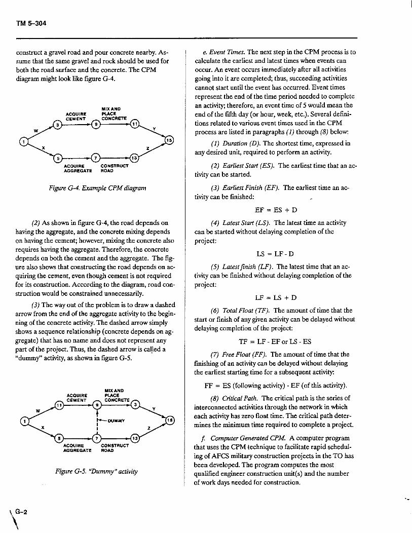
TM 5-304
construct a gravel road and pour concrete nearby. As- sume that the same gravel and rock should be used for both the road surface and the concrete. The CPM diagram might look like figure G-4.
MIX AND ACQUIRE PLACE
<z+;fEz>
ACQUIRE CONSTRUCT AGGREGATE ROAD
Figure G-4. Example CPM diagram
(2) As shown in figure G-4, the road depends on having the aggregate, and the concrete mixing depends on having the cement; however, mixing the concrete also requires having the aggregate. Therefore, the concrete depends on both the cement and the aggregate. The fig- ure also shows that constructing the road depends on ac- quiring the cement, even though cement is not required for its construction. According to the diagram, road con- struction would be constrained unnecessarily.
(3) The way out of the problem is to draw a dashed arrow from the end of the aggregate activity to the begin- ning of the concrete activity. The dashed arrow simply shows a sequence relationship (concrete depends on ag- gregate) that has no name and does not represent any part of the project. Thus, the dashed arrow is caljed a “dummy” activity, as shown in figure G-5.
MIX AND MIX AND ACQUIRE ACQUIRE PLACE PLACE
ACQUIRE ACQUIRE CONSTRUCT CONSTRUCT AGGREGATE AGGREGATE ROAD ROAD
Figure G-5. “Dummy” activity
e. Event Times. The next step in the CPM process is to calculate the earliest and latest times when events can occur. An event occurs immediately after all activities going into it are completed; thus, succeeding activities cannot start until the event has occurred. Event times represent the end of the time period needed to complete an activity; therefore, an event time of 5 would mean the end of the fifth day (or hour, week, etc.). Several defmi- tions related to various event times used in the CPM process are listed in paragraphs (1) through (8) below:
(1) Duration (0). The shortest time, expressed in any desired unit, required to perform an activity.
(2) Earliest Start (ES). The earliest time that an ac- tivity can be started.
(3) Earliest Finish (EF). The earliest time an ac- tivity can be finished:
EF = ES + D
(4) Latest Start (LS). The latest time an activity can be started without delaying completion of the project:
LS = LF-D
(5) Latestfinish (LF). The latest time that an ac- tivity can be finished without delaying completion of the project:
LF=LS+D
(6) Total Float (TF). The amount of time that the start or finish of any given activity can be delayed without delaying completion of the project:
TF = LF-EForLS-ES
(7) Free Float (FF). The amount of time that the finishing of an activity can be delayed without delaying the earliest starting time for a subsequent activity:
FF = ES (following activity) - EF (of this activity).
(8) Critical Path. The critical path is the series of interconnected activities through the network in which each activity has zero float time. The critical path deter- mines the minimum time required to complete a project.
5 Computer Generated CPM. A computer program that uses the CPM technique to facilitate rapid schedul- ing of AFCS military construction projects in the TO has been developed. The program computes the most qualified engineer construction unit(s) and the number of work days needed for construction.
-C
t G-2
\ 1
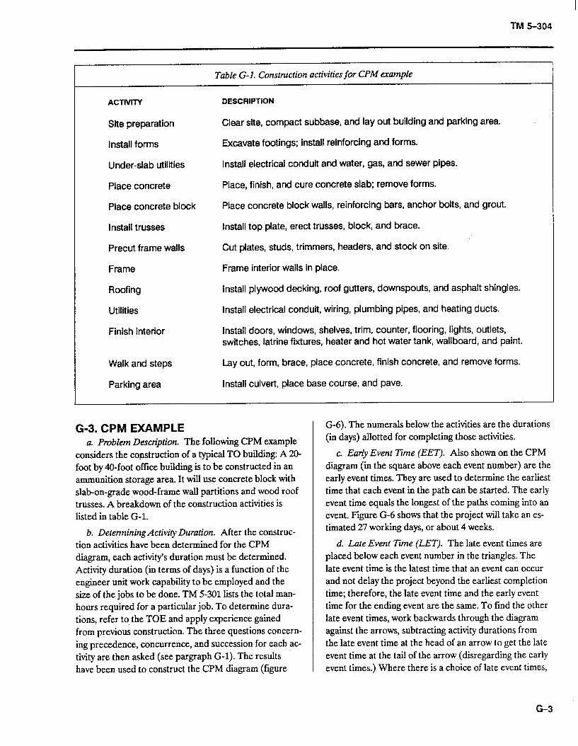
TM 5-304
Table G-l. Construction activities for CPM example
ACTIVITY
Site preparation
Install forms
Under-slab utilities
Place concrete
Place concrete block
Install trusses
Precut frame walls
Frame
Roofing
Utilities
Finish interior
DESCRIPTION
Clear site, compact subbase, and lay out building and parking area. I
Excavate footings; Install reinforcing and forms.
Install electrical conduit and water, gas, and sewer pipes.
Place, finish, and cure concrete slab; remove forms.
Place concrete block walls, reinforcing bars, anchor bolts, and grout.
Install top plate, erect trusses, block, and brace.
Cut plates, studs, trimmers, headers, and stock on site.
Frame interior walls in place.
Install plywood decking, roof gutters, downspouts, and asphalt shingles.
Install electrical conduit, wiring, plumbing pipes, and heating ducts.
Install doors, windows, shelves, trim, counter, flooring, lights, outlets, switches, latrine fixtures, heater and hot water tank, wallboard, and paint.
Walk and steps Lay out, form, brace, place concrete, finish concrete, and remove forms.
Parking area Install culvert, place base course, and pave.
G-3. CPM EXAMPLE a. Problem Description. The following CPM example
considers the copstruction of a typical TO building: A 20- foot by N-foot office building is to be constructed in an ammunition storage area. It will use concrete block with slab-on-grade wood-frame wall partitions and wood roof trusses. A breakdown of the construction activities is listed in table G-l.
b. DeterminingActivity Duration. After the construc- tion activities have been determined for the CPM diagram, each activity’s duration must be determined. Activity duration (in terms of days) is a function of the engineer unit work capability to be employed and the size of the jobs to be done. TM 5-301 lists the total man- hours required for a particular job. To determine dura- tions, refer to the TOE and apply experience gained from previous construction. The three questions concern- ing precedence, concurrence, and succession for each ac- tivity are then asked (see pargraph G-l). The results have been used to construct the CPM diagram (figure
G-6). The numerals below the activities are the durations (in days) allotted for completing those activities.
c. Early Event 7!me (EET). Also shown on the CPM diagram (in the square above each event number) are the early event times. They are used to determine the earliest time that each event in the path can be started. The early event time equals the longest of the paths coming into an event. Figure G-6 shows that the project will take an es- timated 27 working days, or about 4 weeks.
d. Late Event i’?me (LET). The late event times are placed below each event number in the triangles. The late event time is the latest time that an event can occur and not delay the project beyond the earliest completion time; therefore, the late event time and the early event time for the ending event are the same. To find the other late event times, work backwards through the diagram against the arrows, subtracting activity durations from the late event time at the head of an arrow to get the late event time at the tail of the arrow (disregarding the early event times.) Where there is a choice of late event times,
G-3
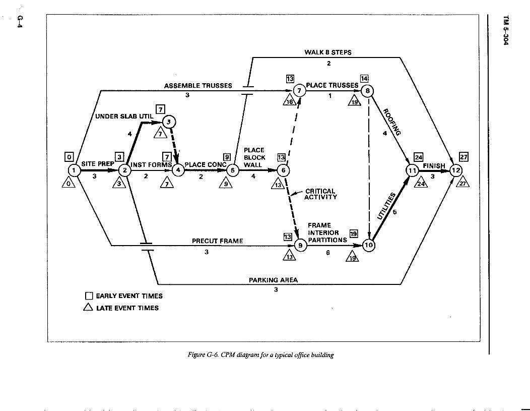
WALK 8 STEPS
ASSEMBLE TRUSSES
UNDER SLAB UTIL - 4
I
i4Y \ [l-2-4-5-66 I I1 l? w
A’ 13
L- CRITICAL \ ACTIVITY \ \ \ FRAME
EBI INTERIOR DARTlTlnNC
Ekl \ & rncbu I rrinwlc
T
3
/ PARKING AREA
3 0 EARLY EVENT TIMES
A LATE EVENT TIMES 7
Figure G-6. CPM diagram for a typical office building
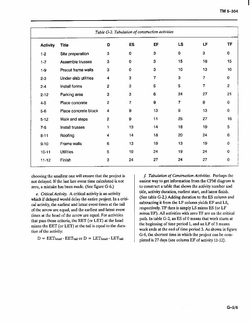
I TM 5-304
Table G-2. Tabulation of construction activities
Activity Title D ES EF Ls LF TF
l-2 Site preparation 3 0 3 0 3 0
l-7 Assemble trusses 3 0 3 15 18 15
1-9 Precut frame walls 3 0 3 10 13 IO
2-3 Under-slab utilities 4 3 7 3 7 0
2-4 Install forms 2 3 5 5 7 2
2-12 Parking area 3 3 6 24 27 21
4-5 Place concrete 2 7 9 7 9 0
5-6 Place concrete block 4 9 13 9 13 0
5-12 Walk and steps 2 9 11 25 27 16
7-8 Install trusses 1 13 14 18 19 5
8-l 1 Roofing 4 14 18 20 24 6
9-10 Frame walls 6 13 19 13 19 0
IO-11 Utilities 5 19 24 19 24 0
II-12 Finish 3 24 27 24 27 0
choosing the smallest one will ensure that the project is not delayed. If the last late event time calculated is not zero, a mistake has been made. (See figure G-6.)
e. CriticalActivity. A critical activity is an activity which if delayed would delay the entire project. In a criti- cal activity, the earliest and latest event times at the tail of the arrow are equal, and the earliest and latest event times at the head of the arrow are equal. For activities that pass those criteria, the EET (or LET) at the head minus the EET (or LET) at the tail is equal to the dura- tion of the activity:
D = EEThead - EETrait or D = LEThead - LETrail
$ Tabulation of Construction Activities. Perhaps the easiest way to get information from the CPM diagram is to construct a table that shows the activity number and title, activity duration, earliest start, and latest finish. (See table G-2.) Adding duration to the ES column and subtracting it from the LF column yields EF and LS, respectively. TF then is simply LS minus ES (or LF minus EF). All activities with zero TF are on the critical path. In table G-2, an ES of 0 means that work starts at the beginning of time period 1, and an LF of 3 means work ends at the end of time period 3. As shown in figure G-6, the shortest time in which the project can be com- pleted is 27 days (see column EF of activity 11-12).
G-516
TM5-304
GLOSSARY
Section I: Abbreviations and Acronyms
AFCS ..... .:. Army Facilities Components System
AMC ......... Army Materiel Command
AR ........... Army regulation
BDP ......... Base Development Plan
B/O .......... back order
BOM ......... bills of materials
CESP ........ Civil Engineer Support Planning
CM .......... commodity manager
CO MO ...... company month
CONUS ...... continental United States
CPM ......... Critical Path Method
CT.A ......... Common Table of Allowances
D ............ duration
DA .......... Department of the Army
DLA ......... Defense Logistics Agency
DOD ......... Department of Defense
EET ......... early event time
EF ........... earliest finish
ES ........... earliest start
FF .......... .-‘free float
FM .......... field manual
GSA ......... General Services Administration
HV .......... heavy
INT .......... initial standard of construction (up to 6 months)
LET. ......... late event time
LF ........... latest finish
LS ........... latest start
LSSA ......... Logistics Systems Support Activity
MACOM ..... Major Army command
ME .......... medium
MH .......... man-hour
MILSTRIP .... Military Standard Requisitioning and Issue Procedure
MIILVAN ..... military-owned demountable container
MO .......... month
MRO ........ material release orders
MT .......... measured ton (40 cubic feet per measured ton)
NICP ......... National Inventory Control Point
NSN ......... National Stock Number (replaces FSN)
OPNS ........ operations
PECS ........ prepackaged expendable contingency supplies
POL ......... petroleum, oil, lubricant
SIMF ......... Stock Item Master Fiie
SP ........... self-propelled
SRC ......... standard requirement code
ST ........... short ton (2,000 pounds)
TACAPS ..... Theater Army Construction Automated Planning System
TF ........... total float
TM .......... technical manual
TO ........... theater of operations
TOE ......... table of organization and equipment
TPR ......... temporary standard of construction (up to 24 months)
TRADOC .... U.S. Army Training and Doctrine Command
TROSCOM ... U.S. Army Troop Support Command
USACE ...... U.S Army Corps of Engineers
USAEDH .... U.S. Army Engineer Division, Huntsville
UTC ......... unit type code
Section II: Abbreviations for Construction Materials
The following are abbreviations for units of issue in TM 5-303 (BOM) and in the SIMF. They are as shown in the Federal Supply Catalog, Cl (Army).
Glossary-l
AM .......... ampoule
AT ........... assortment
AY ........... assembly
BA ........... ball
BD ........... bundle
BE ........... bale
BF ........... board foot
BG ......... ..ba g
BK ......... ..boo k
BL ........... barrel
BO ........... bolt
BR ......... ..b ar
BT ........... bottle
BX ........... box
CA ........... cartridge
CB ........... carboy
CD ........... cubic yard
CE ........... cone
CF ........... cubic foot
CK ........... cake
CL ........... coil
CN ........... can
CO ........... container
CY ........... cylinder
CZ ........... cubic Meter
DR ........... drum
DZ ........... dozen
EA ........... each
Fr ........... foot
GL ........... gallon
GP ........... group
GR ........... gross
HD ........... hundred
HK ........... hank
JR.. .......... jar
KT ........... kit
Glossary-2
LB ........... pound
LG ........... length
LI ............ liter
MC .......... thousand
ME. .......... meal
MR .......... meter
MX .......... thousand
OT ........... outfit
oz ........... ounce
PD ......... ..pa d
PG ......... ..packag e
PM ........... plate
PR ........... pair
PT ........... pint
PZ ........... packet
QT ........... quart
RA ........... ration
RL ........... reel
RM .......... ream
RO ........... roll
SD ........... skid
SE ........... set
SF. ........... square foot
SH ........... sheet
SK ........... skein
SL ........... spool
so ........... shot
SP ............ strip
SY ........... square yard
SX ........... stick
TN ........... ton
TO ........... troy ounce
TU ........... tube
VI ............ vial
YD ........... yard
TM 5-304
The proponent agency for this publication is the office of the Chief of Engineers, United States Army. Users are invited to send comments and suggested improvements on DA Form 2028 (Recommended Changes to Publications and Blank Forms) to HQDA (DAEN-ZCM), WASH, DC 20310-2600.
By Order of the Secretary of the Army,
CARL E. VUONO General, United States Army Chief of Staff
Official: PATRICIA P. HICKERSON Colonel, United States Army The Adjutant General
Distribution: Army: To be distributed in accordance with DA Form 12-34B, Requirements for Nonequipment Technical Manuals.