Embed Size (px)
Citation preview
TM 55-1905-222-14
TECHNICAL MANUAL
OPERATOR, UNIT AND INTERMEDIATE(DIRECT AND GENERAL SUPPORT)
MAINTENANCE MANUAL
LANDING CRAFT, MECHANIZED(LCM-8)
(ROHR AND GUNDERSON MODELS)OPERATOR
MAINTENANCE(1905-01-284-2647 AND 1905-01-284-2648)
This copy is a reprint which includes currentpages from Changes 1 through 3.
Approved for public release; distribution is unlimited
HEADQUARTERS, DEPARTMENT OF THE ARMY20 JULY 1989
INTRODUCTIONPAGE 1-1
OPERATINGINSTRUCTIONS
PAGE 2-1
OPERATORMAINTENANCE
PAGE 3-1
UNITMAINTENANCE
PAGE 4-1
INTERMEDIATEDIRECT SUPPORT
MAINTENANCEPAGE 5-1
INTERMEDIATEGENERALSUPPORT
MAINTENANCEPAGE 6-1
APPENDICES
TM 55-1905-222-14C6
CHANGE HEADQUARTERSDEPARTMENT OF THE ARMY
NO 6 WASHINGTON, D.C., 25 August 1995
Operator, Unit and Intermediate(Direct and General Support)
Maintenance Manual
LANDING CRAFT, MECHANIZED(LCM-8)
(ROHR AND GUNDERSON MODELS)NSN 1905-01-284-2647 and
1905-01-284-2648
DISTRIBUTION STATEMENT A: Approved for public release; distribution is unlimited
TM 55-1905-222-14, 20 July 1989, is changed as follows:
1. Remove and insert pages as indicated below. New or changed text material is indicated by a vertical bar in themargin An illustration change is indicated by a miniature pointing hand.
Remove pages Insert pages2-17 through 2-34 2-17 through 2-342-35 and 2-36 2-35/(2-36 blank)2-37/(2-38 blank) 2-37 and 2-382-39 through 2-72 2-39 through 2-71/(2-72 blank)2-72.1/(2-72 2 blank) ----------
C-1 through C-7/(C-8 blank) C-1 through C-7/(C-8 blank)C-9/(C-10 blank) ----------E-1 and E-2 E-1 and E-2
2. Retain this sheet in front of manual for reference purposes.
TM 55-1905-222-14C5
CHANGE HEADQUARTERSDEPARTMENT OF THE ARMY
NO 5 WASHINGTON, D C, 5 JANUARY 1995
Operator, Unit and Intermediate(Direct and General Support)
Maintenance Manual
LANDING CRAFT, MECHANIZED(LCM-8)
(ROHR AND GUNDERSON MODELS)NSN 1905-01-284-2647
1905-01-284-2648
Current as of 22 November 1994
DISTRIBUTION STATEMENT A: Approved for public release, distribution is unlimited
TM 55-1905-222-14, 20 July 1989, is changed as follows
1. Remove and insert pages as indicated below New or changed text material is indicated by a vertical bar in themargin. An illustration change is indicated by a miniature pointing hand.
Remove pages Insert pages6-19 and 6-20 6-19 and 6-20
2. Retain this sheet in front of manual for reference purposes.
By Order of the Secretary of the Army:
GORDON R SULLIVANGeneral, United States Army
Official Chief of Staff
MILTON H HAMILTONAdministrative Assistant to the
Secretary of the Army07923
DISTRIBUTION:To be distributed in accordance with DA Form 12-25-E, block no 4820, requirements for TM 55-1905-222-14.
TM 55-1905-222-14C4
CHANGE HEADQUARTERSDEPARTMENT OF THE ARMY
NO. 4 WASHINGTON, D C, 4 April 1994
Operator, Unit and Intermediate(Direct and General Support)
Maintenance Manual
LANDING CRAFT, MECHANIZED(LCM-8)
(ROHR AND GUNDERSON MODELS)(NSN 1905-01-284-2647 and 1905-01-284-2648)
DISTRIBUTION STATEMENT A: Approved for public release, distribution is unlimited.
TM 55-1905-222-14, 20 July 1989, is changed as follows
1. Remove and insert pages as indicated below New or changed text material is indicated by a vertical bar in themargin. An illustration change is indicated by a miniature pointing hand.
Remove pages Insert pages
i and ii i and ii2-19 and 2-20 2-19 and 2-204-11 and 4-12 4-11 and 4-12A-1 and A-2 A-1 and A-2C-1 through C-8 C-1 through C-7/(C-8 blank)
2. Retain this sheet in front of manual for reference purposes.
By Order of the Secretary of the Army:
GORDON R SULLIVANGeneral, United States Army
Official: Chief of Staff
MILTON H HAMILTONAdministrative Assistant to the
Secretary of the Army06562
DISTRIBUTION:To be distributed in accordance with DA Form 12-25-E, block no 4820, requirements for TM 55-1905-222-14.
TM 55-1905-222-14C3
CHANGE HEADQUARTERSDEPARTMENT OF THE ARMY
NO. 3 WASHINGTON, D C., 2 SEPTEMBER 1992
Operator, Unit and Intermediate(Direct and General Support)
Maintenance Manual
LANDING CRAFT, MECHANIZED(LCM-8)
(ROHR AND GUNDERSON MODELS)(1905-01-284-2647 AND 1905-01-284-2648
Approved for public release; Distribution is unlimited
TM 55-1905-222-14, 20 July 1989 is changed as follows:
1. Remove and insert pages as indicated below. New or changed text material is indicated by a vertical bar in themargin. An illustration change is indicated by a miniature pointing hand.
Remove pages Insert pages
1 and ii i and ii1-7 and 1-8 1-7 and 1-82-71 and 2-72 2-71 and 2-72
2-72.1/(2-72.2 blank)C-3 through C-8 C-3 through C-9/(C-10 blank)D-1 and D-2E-1 through E-4 E-1 through E-4
2. Retain this sheet in front of manual for reference purposes.
By Order of the Secretary of the Army:GORDON R SULLIVAN
General, United States ArmyOfficial: Chief of Staff
MILTON H. HAMILTONAdministrative Assistant to the
Secretary of the Army02321
DISTRIBUTION:To be distributed in accordance with DA Form 12-25-E, block 4820, Operator, Unit, Direct and General Support
Maintenance requirements for TM 55-1905-222-14.
TM 55-1905-222-14C2
CHANGE HEADQUARTERSDEPARTMENT OF THE ARMY
NO 2 WASHINGTON, D.C., 30 September 1991
Operator, Unit and Intermediate(Direct and General Support)
Maintenance Manual
LANDING CRAFT, MECHANIZED(LCM-8)
(ROHR AND GUNDERSON MODELS)(1905-01-284-2647 AND 1905-01-284-2648)
Approved for public release; distribution is unlimited
TM 55-1905-222-14, 20 July 1989, is changed as follows:
1. Remove and insert pages as indicated below. New or changed text material is indicated by a vertical bar in themargin. An illustration change is indicated by a miniature pointing hand.
Remove pages Insert pages
2-23 and 2-24 2-23 and 2-242-27-through 2-30 2-27 through 2-302-39 through 2-44 2-39 through 2-443-5 and 3-6 3-5 and 3-63-23 through 3-26 3-23 through 3-264-21 and 4-22 4-21 and 4-224-27 through 4-30 4-27 through 4-30C-3 through C-8 C-3 through C-8
2. Retain this sheet in front of manual for reference purposes.
By Order of the Secretary of the Army:GORDON R. SULLIVAN
General, United States ArmyChief of Staff
Official:
PATRICIA P. HICKERSONBrigadier General, United States Army
The Adjutant General
DISTRIBUTION.To be distributed in accordance with DA Form 12-25E, (qty rqr block no. 4820
TM 55-1905-222-14C1
CHANGE HEADQUARTERSDEPARTMENT OF THE ARMY
NO 1. WASHINGTON, D.C., 22 November 1990
Operator, Unit and Intermediate(Direct and General Support)
Maintenance Manual
LANDING CRAFT, MECHANIZED(LCM-8)
(ROHR AND GUNDERSON MODELS)(1905-01-284-2647 AND 1905-01-284-2648)
Approved for public release, distribution is unlimited
TM 55-1905-222-14, 20 July 1989, is changed as follows:
1. Remove and insert pages as indicated below. New or changed text material is indicated by a vertical bar in themargin. An illustration change is indicated by a miniature pointing hand.
Remove pages Insert pages
B-15 and B-16 B-15 and B-16
2. Retain this sheet In front of manual for reference purposes.
By Order of the Secretary of the Army:
CARL E. VUONOGeneral, United States Army
Chief of Staff
Official:THOMAS F. SIKORA
Brigadier General, United States ArmyThe Adjutant General
DISTRIBUTION:To be distributed in accordance with DA Form 12-25E, (qty rqr block no 4820)

TM 55-1905-222-14
This Technical Manual pertains only to ROHR and Gunderson model vessels which have undergone the Service LifeExtension Program (SLEP). If your vessel is still awaiting SLEP application, you must use TM 55-1905-217-12, dated 15August 1974 and TM 55-1905-217-34, dated 8 October 1974.
TM 55-1905-222-14
WARNING
DANGEROUS CHEMICALS
are used in this equipment.
SERIOUS INJURY OR DEATH
may result if personnel fail to observethese safety precautions:
· Be sure all cargo is secure, especially during rough seas.
· Corrosive battery electrolyte, and potassium hydroxide, are potentially dangerous to personnel and property.Wear rubber gloves, apron, and face shield when handling leaking batteries. If potassium hydroxide isspilled on clothing or other material, wash immediately with clean water. If spilled on personnel, start flushingthe affected area immediately with clean water. Continue washing until medical assistance arrives.
· Wipe or flush any spillage. Volatile materials will not be brought aboard; electrical circuits will not beenergized; fuel tanks will not be topped off, and engines will not be started before CO2 firefighting equipment isavailable and operative.
· Observe NO SMOKING rules when refueling. Do not work on live circuits. Tag circuit and warn otherpersonnel not to energize the circuits. Never use a blow torch or other similar means for heating fuel or oillines.
· Dry cleaning solvent (Fed Spec. P-D-680), used to clean parts, is potentially dangerous to personnel andproperty. Clean parts in a well ventilated area. Avoid inhalation of solvent fumes and prolonged exposure ofskin to cleaning solvent. Wash exposed skin thoroughly. Wear eye protection when blowing solvent fromparts. Compressed air used for cleaning purposes will not exceed 30 psi (2.1 kg/cm2).
· Noise: The engines and various other equipment are excessively noisy. Serious hearing loss or deafnesscould occur if this equipment is operated without professionally fitted hearing protection. Unprotected andunnecessary personnel must keep out of the immediate area.
a
TM 55-1905-222-14
WARNING
ASPHYXIATION DANGER
· BE SURE engine room ventilators are open when operating the engine(s). The engine exhaust gases containcarbon monoxide, which is a colorless, odorless, and poisonous gas. Breathing air with carbon monoxideproduces symptoms of headache, dizziness, loss of muscular control, a sleepy feeling, and coma. Braindamage or death can result from heavy exposure. Precautions must be followed to insure crew safety. BEALERT at all times during vehicle operation for exhaust odors and exposure symptoms. If either is presentIMMEDIATELY VENTILATE personnel compartment. If symptoms persist, remove affected person to freshair, keep warm; DO NOT PERMIT PHYSICAL EXERCISE; if necessary, give artificial respiration.
FOR ARTIFICIAL RESPIRATION, REFER TO FM 21-11
BE AWARE- the field protective mask for nuclear-biological-chemical (NBC) protection will not protect youfrom carbon monoxide poisoning. THE BEST DEFENSE AGAINST CARBON MONOXIDE POISONING ISGOOD VENTILATION.
WARNING
LOW VOLTAGEis used in the operation of this equipment.
· Do not be misled by the term "low voltage." Potentials as low as 50 volts may cause death under adverseconditions. Never work on electrical equipment unless there is another person nearby who is familiar with theoperation and hazards of the equipment and who is competent in administering first aid. When thetechnician is aided by operators, he must warn them about dangerous areas. Whenever possible, the inputpower supply to the equipment must be shut off before beginning work on the equipment. Take particular careto ground every capacitor likely to hold a dangerous potential. When working inside the equipment, afterthe power has been turned off, always ground every part before touching it. Do not operate the equipmentwithout all grilles, guards, louvers, and covers in place and tightly secured.
b
TM 55-1905-222-14
WARNING
FIRE OR EXPLOSION HAZARDSERIOUS INJURY OR DEATH
· May result if personnel fail to observe these safety precautions. Hatches must be opened before energizingany electrical circuit or starting engines. Do not smoke or use open flame in the vicinity when servicingbatteries as hydrogen gas, an explosive is generated. Use only distilled water to maintain battery electrolytelevel. Do not fill fuel tank while engine is running. Provide metallic contact between the fuel container andfuel tank to prevent a static spark from igniting fuel.
· When cutting with a torch, or when welding, always station fire watches, ready with fire extinguishers, in thevicinity on both sides of the plate that is being cut or welded.
· Prior to cutting or welding on the ramp, remove drain plugs on both sides of the ramp and check if rampinterior is primer coated. If primer coated, flush thoroughly with steam, carbon dioxide, or water. Do notreinstall drain plugs until the cutting and/or welding operation is completed. Failure to take this precaution mayresult in explosion of accumulated primer vapors.
· When refueling, shut down the electrical system. Observe the no smoking rule. Do not permit anyone tooperate tools or equipment which may produce sparks near the refueling operation. Sparks or fire may ignitethe diesel fuel and produce an explosion.
· Fuel oil and other petroleum products are highly volatile in extreme heat. To minimize the possibility ofexplosion, wipe up all spills at once, see that fuel lines and valves are not leaking and pump bilges regularly.
· Before attempting to remove any compressed air system lines or components, relieve air pressure fromsystem. Failure to do so may result in injury or possible death to maintenance personnel.
· Before disconnecting a line in the hydraulic system, bleed the pressure from that portion of the line. Failure todo so may result in injury or possible death to maintenance personnel.
c/(d blank)
TM 55-1905-222-14
TECHNICAL MANUAL HEADQUARTERSDEPARTMENT OF THE ARMY
55-1905-222-14 WASHINGTON D C., 20 July 1989
Operator, Unit and Intermediate(Direct and General Support)
Maintenance Manual
LANDING CRAFT, MECHANIZED(LCM-8)
(ROHR AND GUNDERSON MODELS)(NSN 1905-01-284-2647 and 1905-01-284-2648)
REPORTING ERRORS AND RECOMMENDING IMPROVEMENTS
You can help improve this manual. If you find any mistakes or if you know of a way to improve theseprocedures, please let us know. Mall your letter or DA Form 2028 (Recommended Changes toPublications and Blank Forms), or DA Form 2028-2 located in the back of this manual directly toCommander, US Army Aviation and Troop Command, ATTN: AMSAT-I-MP, 4300 Goodfellow Blvd., St.Louis, MO 63120-1798. A reply will be furnished directly to you.
DISTRIBUTION STATEMENT A: Approved for public release; distribution is unlimited
TABLE OF CONTENTSPage
CHAPTER 1 INTRODUCTION
Section I General Information ................................ ................................ ................................ ...................... 1-2Section II Equipment Description and Data ................................ ................................ ................................ ..1-5Section III. Technical Principles of Operation................................ ................................ ................................ ..1-16Section IV Service Upon Receipt ................................ ................................ ................................ .................. 1-36
CHAPTER 2 OPERATING INSTRUCTIONS
Section I Description and Use of Operator Controls andIndicators. ................................ ................................ ................................ ................................ .....2-2
Section II Operator Preventive Maintenance Checks and Services................................ ............................... 2-15Section III. Operation Under Usual Conditions . ................................. ................................ ............................ 2-39Section IV Operation Under Unusual Conditions................................ ................................ ............................ 2-63
CHAPTER 3 OPERATOR MAINTENANCESection I. Lubrication Instructions ................................ ................................ ................................ .................3-2Section II. Troubleshooting Procedures................................. ................................ ................................ ......... .3-2Section III Maintenance Procedures................................ ................................ ................................ ...............3-20
Change 4 i
TM 55-1905-222-14
CHAPTER 4 UNIT MAINTENANCE ..................................................................................................................4-1Section I Repair Parts, Special Tools, Test, Measurement, and
Diagnostic Equipment(TMDE); and Support Equipment..... ...........................................................4-3Section II Unit Preventive Maintenance Checks and Services.......................................................................4-3Section III Unit Troubleshooting .....................................................................................................................4-6Section IV Unit Maintenance Procedures. ......................................................................................................4-13Section V Preparation for Storage and Shipment ......... ................................................................................4-73
CHAPTER 5 INTERMEDIATE DIRECT SUPPORT MAINTENANCE.................................................................5-1Section I Repair Parts; Special Tools; Test, Measurement, and
Diagnostic Equipment (TMDE), and Support Equipment .. ............................................................5-4Section II Troubleshooting .............. .............................................................................................................5-4Section III Maintenance Procedures ..............................................................................................................5-12
CHAPTER 6 INTERMEDIATE GENERAL SUPPORT MAINTENANCE .............................................................6-1Section I Repair Parts, Special Tools, Test, Measurement, andI Diagnostic Equipment (TMDE); and Support Equipment ..... .........................................................6-2Section II Troubleshooting ............................................................................................................................6-2Section III Maintenance Procedures ..............................................................................................................6-6
APPENDIX A REFERENCES............ .................................................................................................................A-1
APPENDIX B MAINTENANCE ALLOCATION CHART .......................................................................................B-1
APPENDIX C COMPONENTS OF END ITEM AND BASIC ISSUE ITEMS LISTS ..............................................C-1
APPENDIX D (Deleted)
APPENDIX E EXPENDABLE SUPPLIES AND MATERIALS LIST .............. .......................................................E-1
FOLD OUTS .....................................................................................................................................................FP-1
INDEX ..................................................................................................................................................INDEX-1
Change 4 ii
TM 55-1905-222-14
CHAPTER 1INTRODUCTION
Paragraph
Destruction of Army Materiel to Prevent Enemy Use................................ ................................ ...............1-3
Electrical System ................................ ................................ ................................ ................................ ....1-22
Emergency Bilge System................................ ................................ ................................ ........................ 1-21
Engine Cooling System................................ ................................ ................................ ........................... 1-14
Equipment Characteristics, Capabilities and Features................................ ................................ .............1-8
Equipment Data ................................ ................................ ................................ ................................ ......1-10
Exhaust System................................ ................................ ................................ ................................ ......1-15
Fuel System................................ ................................ ................................ ................................ ............1-13
General (Service Upon Receipt)................................ ................................ ................................ ..............1-24
Glossary................................ ................................ ................................ ................................ .................. 1-7
Hydraulic Starting System................................ ................................ ................................ ....................... 1-17
Hydraulic Steering System................................ ................................ ................................ ...................... 1-18
Inspecting and Servicing the LCM-8................................ ................................ ................................ ........1-25
List of Abbreviations................................ ................................ ................................ ................................ 1-6
Location and Description of Major Components................................ ................................ ....................... 1-9
Maintenance Forms and Records ................................ ................................ ................................ ...........1-2
Marine Sanitation System ................................ ................................ ................................ ....................... 1-23
Oil/Water Separator and Bilge Pumping System................................ ................................ ..................... 1-20
Propulsion System ................................ ................................ ................................ ................................ .1-12
Quality Assurance/Quality Control (QA/QC) ................................ ................................ ............................ 1-5
Ramp Hydraulic System ................................ ................................ ................................ ......................... 1-19
Raw (Sea) Water Cooling System................................ ................................ ................................ ...........1-16
Reporting Equipment Improvement Recommendations (EIRs)................................ ................................ 1-4
Safety, Care and Handling................................ ................................ ................................ ...................... 1-11
Scope ................................ ................................ ................................ ................................ ..................... 1-1
Used Equipment................................ ................................ ................................ ................................ ......1-261-1
TM 55-1905-222-14
Section I. GENERAL INFORMATION
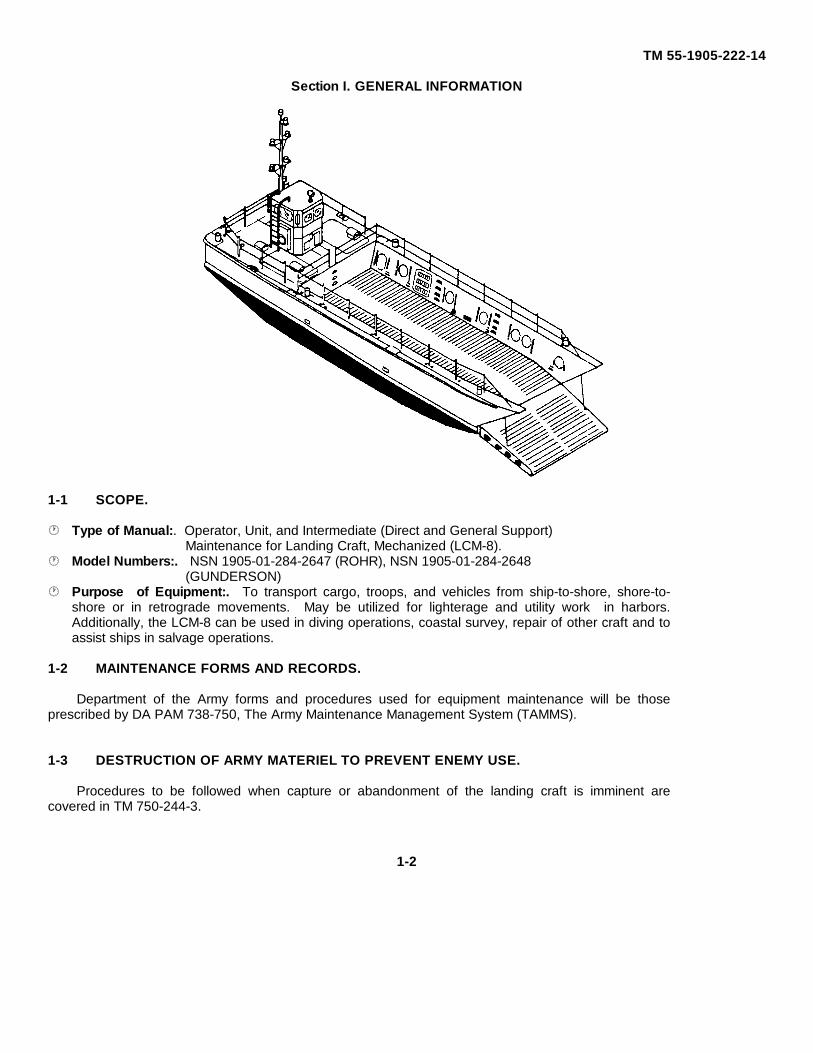
1-1 SCOPE.
Type of Manual:. Operator, Unit, and Intermediate (Direct and General Support)Maintenance for Landing Craft, Mechanized (LCM-8).
Model Numbers:. NSN 1905-01-284-2647 (ROHR), NSN 1905-01-284-2648(GUNDERSON)
Purpose of Equipment:. To transport cargo, troops, and vehicles from ship-to-shore, shore-to-shore or in retrograde movements. May be utilized for lighterage and utility work in harbors.Additionally, the LCM-8 can be used in diving operations, coastal survey, repair of other craft and toassist ships in salvage operations.
1-2 MAINTENANCE FORMS AND RECORDS.
Department of the Army forms and procedures used for equipment maintenance will be thoseprescribed by DA PAM 738-750, The Army Maintenance Management System (TAMMS).
1-3 DESTRUCTION OF ARMY MATERIEL TO PREVENT ENEMY USE.
Procedures to be followed when capture or abandonment of the landing craft is imminent arecovered in TM 750-244-3.
1-2
TM 55-1905-222-14
1-4 REPORTING EQUIPMENT IMPROVEMENT RECOMMENDATIONS (EIRs).
If your landing craft needs improvement, let us know. Send us an EIR. You, the user, are the only one who can tellus what you don't like about your equipment. Let us know why you don't like the design or performance. Put it on an SF368 (Quality Deficiency Report). Mail it direct to Commander, US Army Troop Support Command, ATTN. AMSTR - QX,4300 Goodfellow Boulevard, St. Louis, MO 63120-1798. We will send you a reply.
1-5 QUALITY ASSURANCE/QUALITY CONTROL (QA/QC).
The contents of this technical manual have been validated against engineering source data. Operator and maintenanceinstructions have been validated against the system/equipment by actual demonstration as required.
1-6 LIST OF ABBREVIATIONS.
The following is a list of abbreviations of components, maintenance terms and forms associated with the LCM-8:
DPDT - Double Pole, Double Throw Switch
DS/GS - Direct Support/General Support
EIR - Equipment Improvement Recommendation
FR - Frame
HWT - High Water Temperature
LCM - Landing Craft, Mechanized
LOP - Low O11 Pressure
MAC - Maintenance Allocation Chart
MSD - Marine Sanitation Device
MTOE - Modified Table of Organizational Equipment
OWS - Oil/Water Separator
PMCS - Preventive Maintenance Checks and Services
QAI - Quality Assurance Inspections
RAI - Rudder Angle Indicator
RIL - Red Indicating Lamps
1-3
TM 55-1905-222-14
RMHS - Remote Magnetic Heading System
RPSTL - Repair Parts and Special Tools List
TAMMS - The Army Maintenance Management System
TMDE - Test, Measurement and Diagnostic Equipment
TROSCOM - Troop Support Command
1-7 GLOSSARY.
The following defines technical, nautical and mission-related terms used in this training manual:
Accumulators - Devices that receive, store, build-up and release hydraulic oil in the LCM-8 hydraulicstarting system.
AnaerobicDecomposition - Sewage decay occurring in absence of oxygen. A natural action accelerated by the
addition of selected bacteria.
Athwarthsip - Across the ship from side to side.
Bilge - The lowest part of a ship's inner hull.
BiochemicalOxygen. - The ratio of oxygen available to the oxygen required for stabiliza-Demand tion of sewage.
Coalesce - Action arising from combination of distinct elements, such as oil/water mixture and otheroil in fuel system.
Coaming - The raised frame (around the hatchway) that keeps out water.
Effluent - The outflow of sewage.
Hondu - A drum key, a device to hold ramp cable on winch drum to prevent cable from runningout.
Lazarette. - Compartment between decks used as a storeroom for repair parts, line and auxiliaryequipment. On the LCM-8, a compartment aft of the engine room.
Weir - Divider that controls or diverts flow of sewage in marine sanitation system.
1-4
TM 55-1905-222-14
Section II. EQUIPMENT DESCRIPTION AND DATA
1-8 EQUIPMENT CHARACTERISTICS, CAPABILITIES AND FEATURES.
1-8.1. General. The LCM-8 is a type of watercraft intended for use in rough or exposed waters. It is capable ofoperating through breakers and grounding on a beach, remaining upright and tight, and retracting under its own power. Itcan be transported to overseas destinations as cargo aboard transport ships. This craft is all- weather operational in seastate 1, 2 and 3. Other capabilities and features are as follows:
MOBILITY DATA
Speed (light) 11 knots (20 4 km/hr)(loaded) 9 knots (16.7 km/hr)
Cruising Range (light) 332 nautical miles (614.9 km)(loaded) 271 nautical miles (501.9 km)
HULL AND ACCOMMODATIONS DATA
Length, overall 74 ft (22 55m)Beam, extreme 21 ft 0 5/8 In (6 .40m)Beam, molded 20 ft 11 3/4 in (6 .32m)Depth, molded amid ships 9 ft 4 in (284. 5cm)Draft, loaded, mean 4 ft 6 in (137. 16cm)Freeboard, loaded, mean 4 ft 10 in (147. 32cm)Displacement (light) 58. 81 long tons (59. 8t)
(loaded) 116. 07 long tons (117. 9t)
Cargo Space (length) 42 ft. 9 in (13m)(width) 14 ft 6 in (4. 4m)
AnchorNumber 1Type 70 pounds, "Danforth"
Mark 2Line 75 fathoms, 3 inch
nylonPropellers
Number 2Type Manganese bronze,
3-blade, 34-inchdiameter, 22-inch pitch
ComplementCrew 6Troops 200 combat-equipped
1-5
TM 55-1905-222-14
1-8.2 Hull Structural Features. Refer to Foldout-1. The hull is an all steel welded structure. There are ninewatertight bulkheads at frames 3, 7, 11, 15, 19, 23, 27, 31 and 39. The compartments forward of frame 31 below thecargo deck form seven sealed watertight buoyancy holds or voids. The cargo deck extends forward of frame 31 to thebow ramp. The main deck extends from the bow aft along the sides of the cargo well to the full main deck over theengine room and lazarette. The compartment below the main deck from frame 31 aft to frame 39 is the engine room.The compartment aft of frame 39 to the transom is the lazarette. The pilothouse superstructure is located on the maindeck, centerline, at frame 35. Port and starboard skeg keels project from the underwater hull between frames 29 and 39.Tunnels in the keels aft of frame 39 provide clearance for the propellers. V- shaped struts are welded to each skeg keeland to the hull between frames 41 and 42. Seven zinc anodes are provided for underwater hull cathodic protection.
1-8.2.1 Main Deck. The main deck extends the entire length of the LCM-8. A full deck is provided from the transomforward to frame 31. Between the bow and frame 31, the main deck forms port and starboard walkways along the sidesof the cargo well. Engine room cover plates with integral ventilators are bolted in the deck, port and starboard, betweenframes 31 and 38. A lazarette cover plate is bolted in the deck, port of the centerline aft of frame 39. Six 15-inchchocks are provided in pairs, port and starboard, on the bow, at frame 37, and on the transom. Six 12-inch mooring bittsare provided in pairs, port and starboard, at frames 3, 29 and 43. Four lifting eyes are provided in pairs, port andstarboard, at frames 15 and 31.
a. Engine cooling system expansion tank fill deck plates are provided, port and starboard, in the deck aft of frame31. Fuel tank sounding deck plates are provided, port and starboard, in the deck aft of frame 39. Port and starboarddeck plates are provided on the transom for installing the emergency steering tiller. A fuel fill connection and fuel tankvent connection are located behind the pilothouse on the centerline at frame 39. Anchor brackets are welded to thedeck, port side, between frames 41 and 42, for securing the anchor. Fourteen deck plates are provided in pairs, port andstarboard, at frames 7, 11, 19, and 27 for venting the sealed watertight holds below the cargo deck. A single lifeline with28 portable stanchions is provided for personnel safety. A double lifeline is provided aft of frame 31. Twelve fenderlashing eyes are welded to the deck, six per side, at equal intervals, port and starboard.
b. Two watertight access hatches are located on the main deck. One 30 by 24- inch raised watertight hatchlocated port of the centerline aft of frame 33 provides access to the engine room. Another 30 by 24-inch raisedwatertight hatch located port of the centerline on the lazarette cover plate aft of frame 39 provides access to the lazarettecompartment.
c. A telescoping, hinged mast is rigged on the main deck near centerline immediately aft of the pilothousesuperstructure. The telescoping mast is the foundation for the masthead light, the anchor light, the upper and lower not-under-command lights, the remote magnetic heading transmitter, and the halyard for the ensign. The mast is designedto be manually extended to its full height for use in the vertical position, and to be completely lowered and hinged tostarboard for horizontal stowage on deck. The mast hinged foundation is welded to the deck adjacent to centerline atframe 39. Mast support brackets and electrical connection boxes for the mast lights and remote magnetic headingtransmitter are positioned on the rear of the pilothouse bulkhead. Securing staples with lashing material for stowing themast in the horizontal position are welded to the deck starboard of the centerline at frame 43.
1-6
TM 55-1905-222-14
1-8.2.2 Pilothouse. The pilothouse is a 6-foot long by 7-foot high by 6-foot wide superstructrure mounted on the maindeck, centerline, between frames 35 and 39. The pilothouse superstructure is steel to a height of 5 feet above the maindeck and topped by an aluminum removable canopy containing windows that allow the coxswain 360-degree visibility.The canopy is designed to be removed when the LCM-8 is engaged in operations requiring low profile configurationEntrance to the pilothouse is through 42 by 15-inch open doorways in the superstructure, port and starboard. The portand starboard lights are mounted on welded brackets on the sides of the canopy at frame 39. The stern light is mountedon a welded bracket attached to the static isolator cabinet behind the pilothouse. Two 24-inch life rings are stowed, portand starboard, in brackets on the sides of the superstructure. The emergency steering tiller is stowed in brackets belowthe starboard life ring. The electric horn is on a bracket, forward of the pilothouse starboard superstructure. Sevenrectangular peep holes are cut in the pilothouse superstructure to increase visibility for the coxswain. A search light ismounted on top of the canopy. The ship's bell is mounted on a bracket, forward of the pilothouse superstructure.
1-8.2.3 Cargo Well. The cargo well extends aft from the bow ramp to frame 31. The cargo well is entirely above thewaterline. The cargo well deck slopes downward aft of frame 7 to the bulkhead at frame 31, and forward of frame 7 tothe bow. Freeing ports are provided in the wing walls at frames 16 and 29, port and starboard, to drain accumulatedwater. Scuppers are provided at frame 3, port and starboard, to drain water from the forward section of the cargo welldeck. Steel tread bars welded to the cargo well deck provide traction for heavy equipment carried as cargo on the LCM-8.
a. Cargo lashing rings and padeyes are provided along the port and starboard wing walls for securing cargo.Sixteen 18-inch diameter manholes are flush bolted in the wing walls, port and starboard. One 18 by 24-inch manhole isflush bolted in the starboard wing wall, aft. These manholes provide access to the normally sealed hold areas below thecargo well deck. Pipe guards welded to the cargo well wing walls protect the manholes and hatches from possibledamage due to shifting cargo. Steps recessed in the wing walls at frames 10 and 20, port and starboard, and in the aftbulkhead at frame 31 provide personnel access to the cargo well from the main deck. Emergency ramp hosting padeyesare welded to the wing walls, port and starboard, at frame 0 just below the main deck.
b. Two 30 by 36-inch individually dogged flush watertight access hatches are provided in the cargo well. One 30by 36-inch hatch located in the starboard wing wall at frame 5 provides access to the hydraulic ramp winch. The other 30by 36-inch hatch, located in the port wing wall at frame 23, provides access to the dry stowage locker in buoyancy hold 5.Threaded bronze hoisting eyes with T-handle wrenches are provided adjacent to both 30 by 36-inch access hatches. Thecargo well is illuminated by two lights, port and starboard, recessed into bulkhead 31. Two 8-foot boat hooks areprovided with the LCM-8 and are stowed in brackets, port and starboard, along the cargo well wing walls between frames7 and 15. A hand pump for manually actuating the hydraulic winch in case of hydraulic fluid pressure failure is located ina recess in the starboard wing wall at frame 9.
1-8.2.4 Bow Ramp. The bow ramp is a welded steel structure hinged at six locations on the bow just below thewaterline at frame 3. The ramp hinges pivot on 2-inch diameter carbon steel hinge pins. The E hinge brackets arewelded to the ramp and to the hull. Thirty-two steel tread bars welded to the ramp deck provide traction for heavyequipment carried as cargo on the LCM-8.
Change 3 1-7
TM 55-1905-222-14
The bow ramp is raised and lowered by a hydraulic powered winch and cable system. A transverse pipe, whichpasses through the bow ramp interior forward of frame 0 with associated pivoting sheaves at each end, serves as a ramphoisting cable guide. Ramp attachments for emergency mechanical hoist cables are provided in the bow ramp deck, portand starboard, at frame A. Port and starboard preventers are provided to secure the bow in full hoist position. The bowramp preventers are shackled to the forward lifeline anchor fittings, port and starboard, on the main deck and attach tothe bow ramp with eye slip hooks. Ratchet load binders are installed in the preventers to cinch the bow ramp into the fullhoist position. A synthetic rubber gasket provides a watertight seal between the bow ramp and the cargo well when thebow ramp is at full hoist and cinched in position.
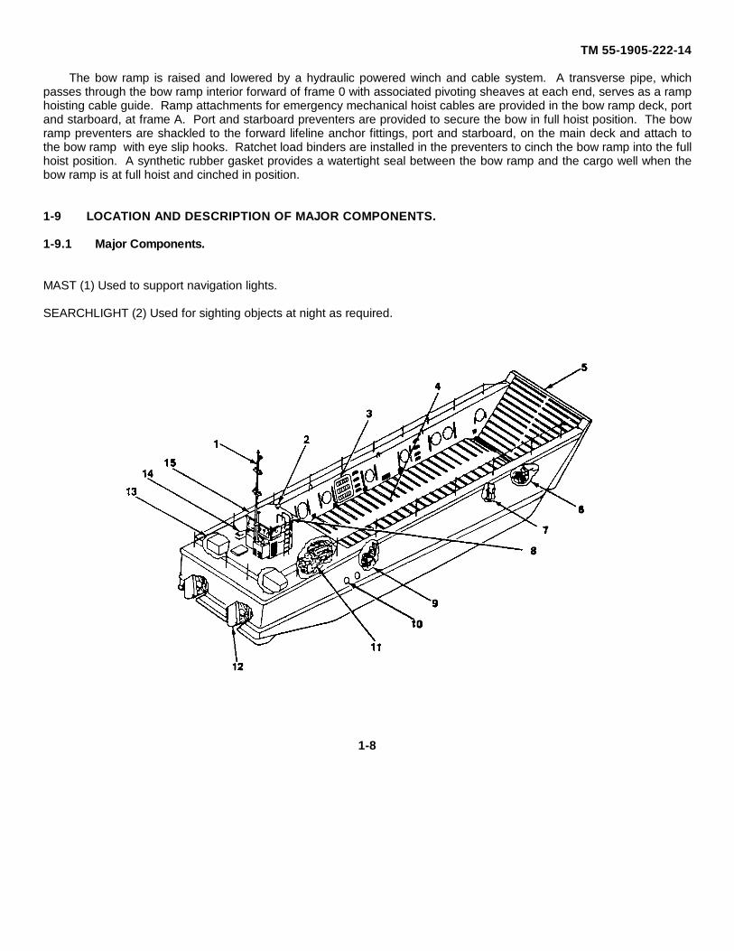
1-9 LOCATION AND DESCRIPTION OF MAJOR COMPONENTS.
1-9.1 Major Components.
MAST (1) Used to support navigation lights.
SEARCHLIGHT (2) Used for sighting objects at night as required.
1-8

TM 55-1905-222-14
1-9 1 Major Components (continued).
STOWAGE LOCKER (3) Used for storage of equipment.
CARGO WELL (4) Used to carry troops, vehicles and other cargo.
RAMP (5) Used to load and off-load troops, vehicles and other cargo.
WINCH (6) Used to reel in or reel out winch cable to raise or lower the ramp.
RAMP HAND PUMP (7) Used to manually lower the ramp in an emergency.
HORN (8) Used to give signals to other vessels.
MARINE SANITATION DEVICE (9) Used to treat sewage from the marine head.
EXHAUST PORTS (10) Used to expel engine exhaust fumes from the engine exhaust manifold.
PROPULSION ENGINE (11). Used primarily to propel the craft Also used to drive other engine accessories.
RUDDERS (12). Used to direct the thrust of the propellers in order to maneuver the vessel.
FUEL TANK (13). Used to store fuel oil for the engines.
ENGINE ROOM VENTILATORS (14). Used to bring fresh air into the engine room and ventilate the space.
PILOTHOUSE (15) Used as a station for operating the vessel.
1-9
TM 55-1905-222-14
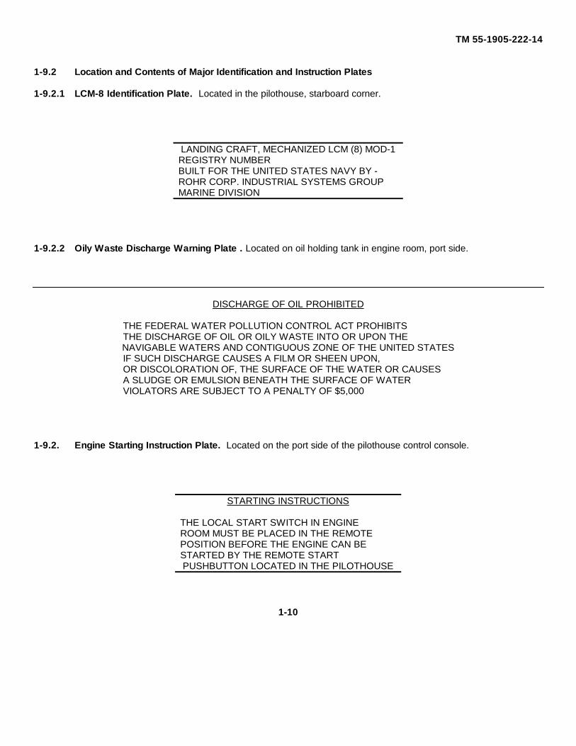
1-9.2 Location and Contents of Major Identification and Instruction Plates
1-9.2.1 LCM-8 Identification Plate. Located in the pilothouse, starboard corner.
LANDING CRAFT, MECHANIZED LCM (8) MOD-1REGISTRY NUMBERBUILT FOR THE UNITED STATES NAVY BY -ROHR CORP. INDUSTRIAL SYSTEMS GROUPMARINE DIVISION
1-9.2.2 Oily Waste Discharge Warning Plate . Located on oil holding tank in engine room, port side.
DISCHARGE OF OIL PROHIBITED
THE FEDERAL WATER POLLUTION CONTROL ACT PROHIBITSTHE DISCHARGE OF OIL OR OILY WASTE INTO OR UPON THENAVIGABLE WATERS AND CONTIGUOUS ZONE OF THE UNITED STATESIF SUCH DISCHARGE CAUSES A FILM OR SHEEN UPON,OR DISCOLORATION OF, THE SURFACE OF THE WATER OR CAUSESA SLUDGE OR EMULSION BENEATH THE SURFACE OF WATERVIOLATORS ARE SUBJECT TO A PENALTY OF $5,000
1-9.2. Engine Starting Instruction Plate. Located on the port side of the pilothouse control console.
STARTING INSTRUCTIONS
THE LOCAL START SWITCH IN ENGINEROOM MUST BE PLACED IN THE REMOTEPOSITION BEFORE THE ENGINE CAN BESTARTED BY THE REMOTE STARTPUSHBUTTON LOCATED IN THE PILOTHOUSE
1-10
TM 55-1905-222-14
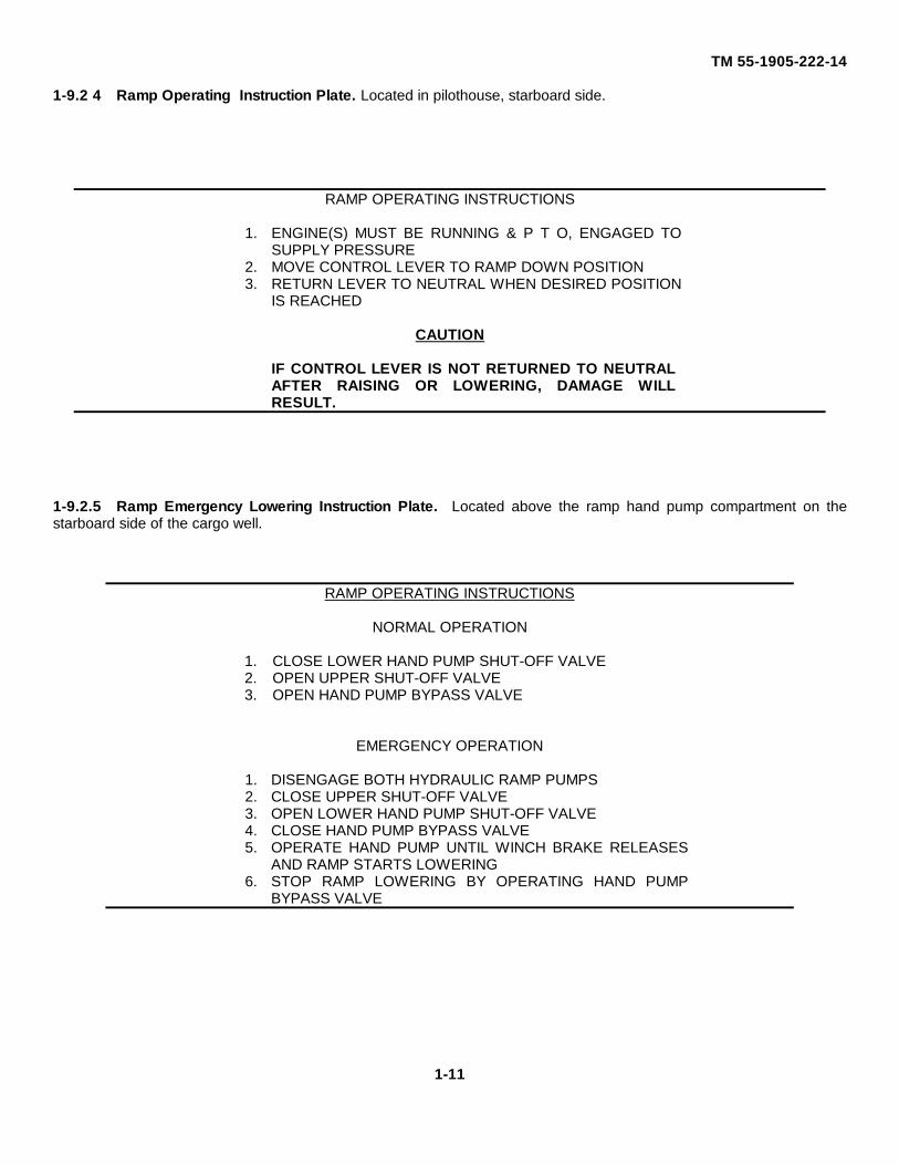
1-9.2 4 Ramp Operating Instruction Plate. Located in pilothouse, starboard side.
RAMP OPERATING INSTRUCTIONS
1. ENGINE(S) MUST BE RUNNING & P T O, ENGAGED TOSUPPLY PRESSURE
2. MOVE CONTROL LEVER TO RAMP DOWN POSITION3. RETURN LEVER TO NEUTRAL WHEN DESIRED POSITION
IS REACHED
CAUTION
IF CONTROL LEVER IS NOT RETURNED TO NEUTRALAFTER RAISING OR LOWERING, DAMAGE WILLRESULT.
1-9.2.5 Ramp Emergency Lowering Instruction Plate. Located above the ramp hand pump compartment on thestarboard side of the cargo well.
RAMP OPERATING INSTRUCTIONS
NORMAL OPERATION
1. CLOSE LOWER HAND PUMP SHUT-OFF VALVE2. OPEN UPPER SHUT-OFF VALVE3. OPEN HAND PUMP BYPASS VALVE
EMERGENCY OPERATION
1. DISENGAGE BOTH HYDRAULIC RAMP PUMPS2. CLOSE UPPER SHUT-OFF VALVE3. OPEN LOWER HAND PUMP SHUT-OFF VALVE4. CLOSE HAND PUMP BYPASS VALVE5. OPERATE HAND PUMP UNTIL WINCH BRAKE RELEASES
AND RAMP STARTS LOWERING6. STOP RAMP LOWERING BY OPERATING HAND PUMP
BYPASS VALVE
1-11
TM 55-1905-222-14
1-9.2.6 Emergency Steering Instruction Placard. Located in the lazarette.
EMERGENCY STEERING
1. IN CASE OF FAILURE OF HAND PUMP, PROCEED WITH MANUAL STEERINGFROM WHEEL
2. IN CASE OF FAILURE OF MANUAL STEERING FROM WHEEL, PROCEED TOUSE EMERGENCY TILLER AS FOLLOWS:
(1) PULL OUT ACCESS PLATE IN DECK OVER ONE RUDDER STOCK(2) UNSHIP AND INSERT EMERGENCY TILLER AT OPEN RUDDER STOCK(3) ENTER LAZARETTE AND PULL OUT EYE PIN TO DISCONNECT HYD
CYLINDERS
1-9.2.7 Oil/Water Separator and Bilge Pumping System Operating Instruction Placard. Located on port side ofengine room below the holding tank The contents of this placard are shown on Foldout - 2.
1-12
TM 55-1905-222-14
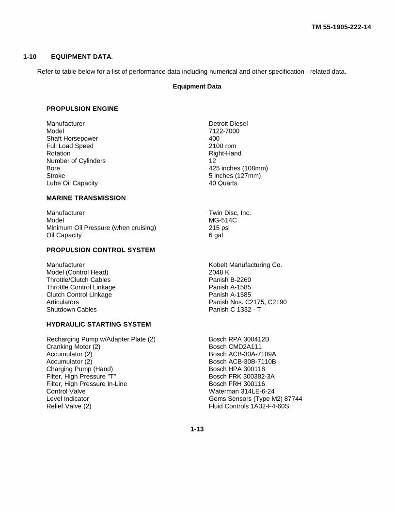
1-10 EQUIPMENT DATA.
Refer to table below for a list of performance data including numerical and other specification - related data.
Equipment Data
PROPULSION ENGINE
Manufacturer Detroit DieselModel 7122-7000Shaft Horsepower 400Full Load Speed 2100 rpmRotation Right-HandNumber of Cylinders 12Bore 425 inches (108mm)Stroke 5 inches (127mm)Lube Oil Capacity 40 Quarts
MARINE TRANSMISSION
Manufacturer Twin Disc, Inc.Model MG-514CMinimum Oil Pressure (when cruising) 215 psiOil Capacity 6 gal
PROPULSION CONTROL SYSTEM
Manufacturer Kobelt Manufacturing Co.Model (Control Head) 2048 KThrottle/Clutch Cables Panish B-2260Throttle Control Linkage Panish A-1585Clutch Control Linkage Panish A-1585Articulators Panish Nos. C2175, C2190Shutdown Cables Panish C 1332 - T
HYDRAULIC STARTING SYSTEM
Recharging Pump w/Adapter Plate (2) Bosch RPA 300412BCranking Motor (2) Bosch CMD2A111Accumulator (2) Bosch ACB-30A-7109AAccumulator (2) Bosch ACB-30B-7110BCharging Pump (Hand) Bosch HPA 300118Filter, High Pressure "T" Bosch FRK 300382-3AFilter, High Pressure In-Line Bosch FRH 300116Control Valve Waterman 314LE-6-24Level Indicator Gems Sensors (Type M2) 87744Relief Valve (2) Fluid Controls 1A32-F4-60S
1-13
TM 55-1905-222-14
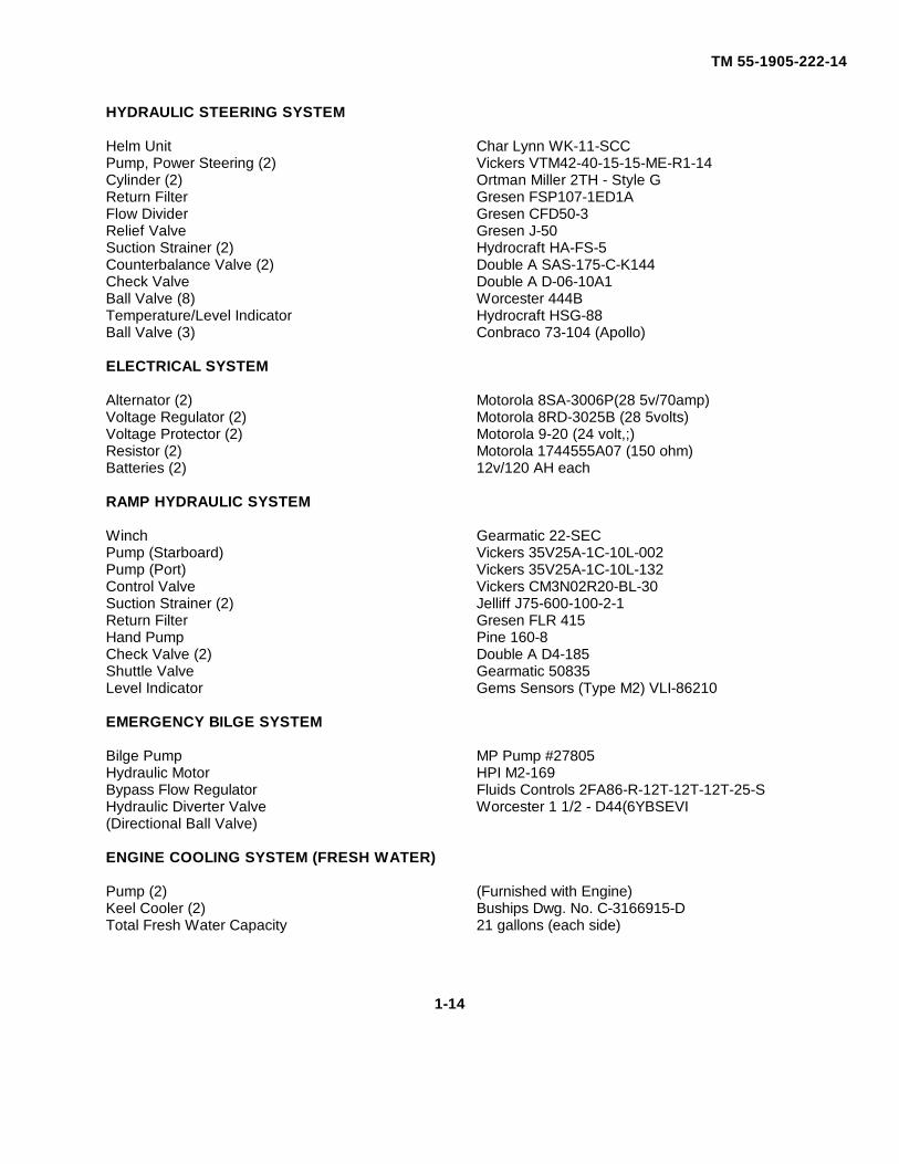
HYDRAULIC STEERING SYSTEM
Helm Unit Char Lynn WK-11-SCCPump, Power Steering (2) Vickers VTM42-40-15-15-ME-R1-14Cylinder (2) Ortman Miller 2TH - Style GReturn Filter Gresen FSP107-1ED1AFlow Divider Gresen CFD50-3Relief Valve Gresen J-50Suction Strainer (2) Hydrocraft HA-FS-5Counterbalance Valve (2) Double A SAS-175-C-K144Check Valve Double A D-06-10A1Ball Valve (8) Worcester 444BTemperature/Level Indicator Hydrocraft HSG-88Ball Valve (3) Conbraco 73-104 (Apollo)
ELECTRICAL SYSTEM
Alternator (2) Motorola 8SA-3006P(28 5v/70amp)Voltage Regulator (2) Motorola 8RD-3025B (28 5volts)Voltage Protector (2) Motorola 9-20 (24 volt,;)Resistor (2) Motorola 1744555A07 (150 ohm)Batteries (2) 12v/120 AH each
RAMP HYDRAULIC SYSTEM
Winch Gearmatic 22-SECPump (Starboard) Vickers 35V25A-1C-10L-002Pump (Port) Vickers 35V25A-1C-10L-132Control Valve Vickers CM3N02R20-BL-30Suction Strainer (2) Jelliff J75-600-100-2-1Return Filter Gresen FLR 415Hand Pump Pine 160-8Check Valve (2) Double A D4-185Shuttle Valve Gearmatic 50835Level Indicator Gems Sensors (Type M2) VLI-86210
EMERGENCY BILGE SYSTEM
Bilge Pump MP Pump #27805Hydraulic Motor HPI M2-169Bypass Flow Regulator Fluids Controls 2FA86-R-12T-12T-12T-25-SHydraulic Diverter Valve Worcester 1 1/2 - D44(6YBSEVI(Directional Ball Valve)
ENGINE COOLING SYSTEM (FRESH WATER)
Pump (2) (Furnished with Engine)Keel Cooler (2) Buships Dwg. No. C-3166915-DTotal Fresh Water Capacity 21 gallons (each side)
1-14
TM 55-1905-222-14
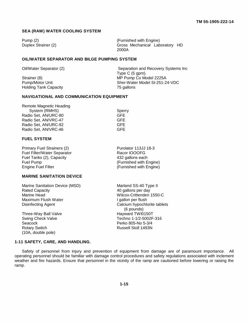
SEA (RAW) WATER COOLING SYSTEM
Pump (2) (Furnished with Engine)Duplex Strainer (2) Gross Mechanical Laboratory HD
2000A
OIL/WATER SEPARATOR AND BILGE PUMPING SYSTEM
Oil/Water Separator (2) Separation and Recovery Systems IncType C (5 gpm).
Strainer (8) MP Pump Co Model 2225APump/Motor Unit Sher-Water Model SI-251-24-VDCHolding Tank Capacity 75 gallons
NAVIGATIONAL AND COMMUNICATION EQUIPMENT
Remote Magnetic HeadingSystem (RMHS) Sperry
Radio Set, AN/URC-80 GFERadio Set, AN/VRC-47 GFERadio Set, AN/URC-92 GFERadio Set, AN/VRC-46 GFE
FUEL SYSTEM
Primary Fuel Strainers (2) Purolator 113JJ 18-3Fuel Filter/Water Separator Racor IOOOFGFuel Tanks (2), Capacity 432 gallons eachFuel Pump (Furnished with Engine)Engine Fuel Filter (Furnished with Engine)
MARINE SANITATION DEVICE
Marine Sanitation Device (MSD) Marland SS-40 Type IIRated Capacity 40 gallons per dayMarine Head Wilcox-Crittenden 1550-CMaximum Flush Water I gallon per flushDisinfecting Agent Calcium hypochlorite tablets
(6 pounds)Three-Way Ball Valve Hayward TWI0150TSwing Check Valve Techno 1-1/2-5002F-316Seacock Perko 805-No 5-3/4Rotary Switch Russell Stoll 1493N(10A, double pole)
1-11 SAFETY, CARE, AND HANDLING.
Safety of personnel from injury and prevention of equipment from damage are of paramount importance. Alloperating personnel should be familiar with damage control procedures and safety regulations associated with inclementweather and fire hazards. Ensure that personnel in the vicinity of the ramp are cautioned before lowering or raising theramp.
1-15
TM 55-1905-222-14
Section III. TECHNICAL PRINCIPLES OF OPERATION
1-12 PROPULSION SYSTEM.
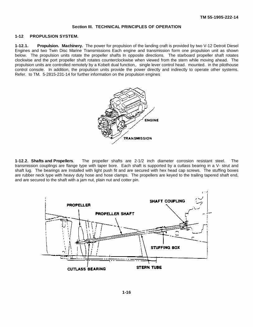
1-12.1. Propulsion. Machinery. The power for propulsion of the landing craft is provided by two V-12 Detroit DieselEngines and two Twin Disc Marine Transmissions Each engine and transmission form one propulsion unit as shownbelow. The propulsion units rotate the propeller shafts In opposite directions. The starboard propeller shaft rotatesclockwise and the port propeller shaft rotates counterclockwise when viewed from the stern while moving ahead. Thepropulsion units are controlled remotely by a Kobelt dual function,. single lever control head. mounted. in the pilothousecontrol console. In addition, the propulsion units provide the power directly and indirectly to operate other systems.Refer. to TM. 5-2815-231-14 for further information on the propulsion engines
1-12.2. Shafts and Propellers. The propeller shafts are 2-1/2 inch diameter corrosion resistant steel. Thetransmission couplings are flange type with taper bore. Each shaft is supported by a cutlass bearing in a V- strut andshaft lug. The bearings are Installed with light push fit and are secured with hex head cap screws. The stuffing boxesare rubber neck type with heavy duty hose and hose clamps. The propellers are keyed to the trailing tapered shaft end,and are secured to the shaft with a jam nut, plain nut and cotter pin.
1-16
TM 55-1905-222-14
1-13 FUEL SYSTEM.
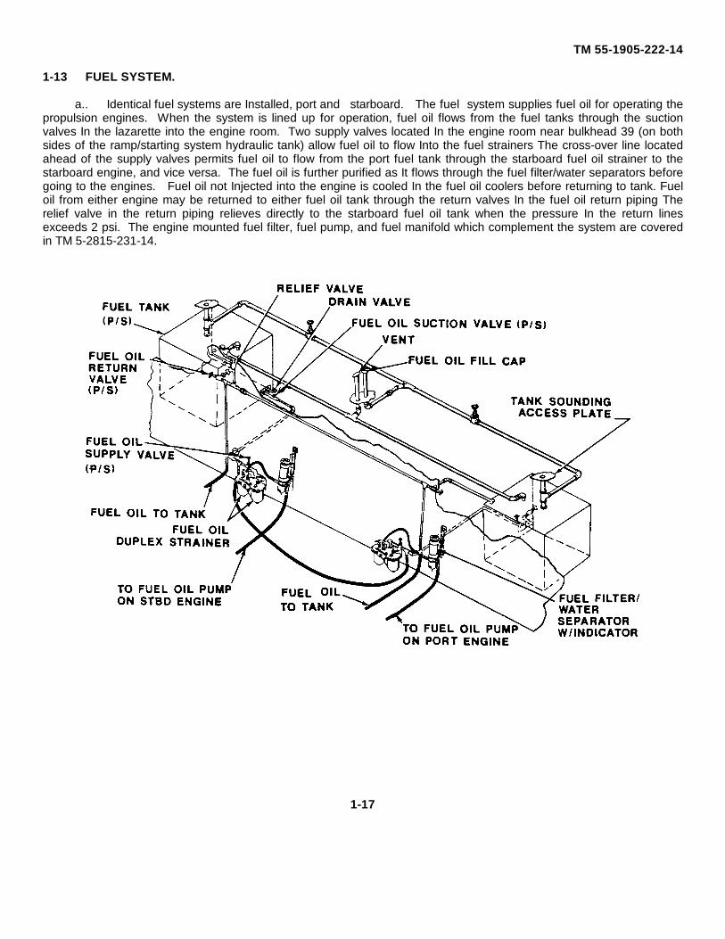
a.. Identical fuel systems are Installed, port and starboard. The fuel system supplies fuel oil for operating thepropulsion engines. When the system is lined up for operation, fuel oil flows from the fuel tanks through the suctionvalves In the lazarette into the engine room. Two supply valves located In the engine room near bulkhead 39 (on bothsides of the ramp/starting system hydraulic tank) allow fuel oil to flow Into the fuel strainers The cross-over line locatedahead of the supply valves permits fuel oil to flow from the port fuel tank through the starboard fuel oil strainer to thestarboard engine, and vice versa. The fuel oil is further purified as It flows through the fuel filter/water separators beforegoing to the engines. Fuel oil not Injected into the engine is cooled In the fuel oil coolers before returning to tank. Fueloil from either engine may be returned to either fuel oil tank through the return valves In the fuel oil return piping Therelief valve in the return piping relieves directly to the starboard fuel oil tank when the pressure In the return linesexceeds 2 psi. The engine mounted fuel filter, fuel pump, and fuel manifold which complement the system are coveredin TM 5-2815-231-14.
1-17
TM 55-1905-222-14
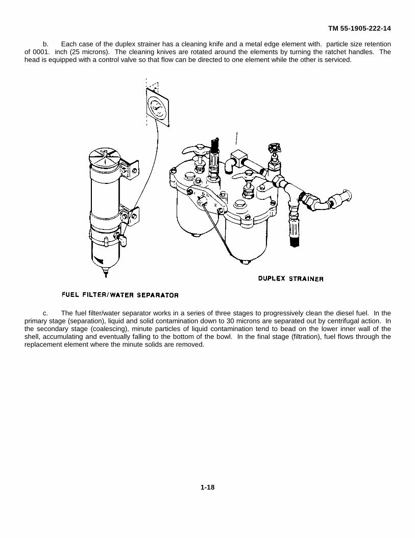
b. Each case of the duplex strainer has a cleaning knife and a metal edge element with. particle size retentionof 0001. inch (25 microns). The cleaning knives are rotated around the elements by turning the ratchet handles. Thehead is equipped with a control valve so that flow can be directed to one element while the other is serviced.
c. The fuel filter/water separator works in a series of three stages to progressively clean the diesel fuel. In theprimary stage (separation), liquid and solid contamination down to 30 microns are separated out by centrifugal action. Inthe secondary stage (coalescing), minute particles of liquid contamination tend to bead on the lower inner wall of theshell, accumulating and eventually falling to the bottom of the bowl. In the final stage (filtration), fuel flows through thereplacement element where the minute solids are removed.
1-18
TM 55-1905-222-14
1-14 ENGINE COOLING SYSTENI.
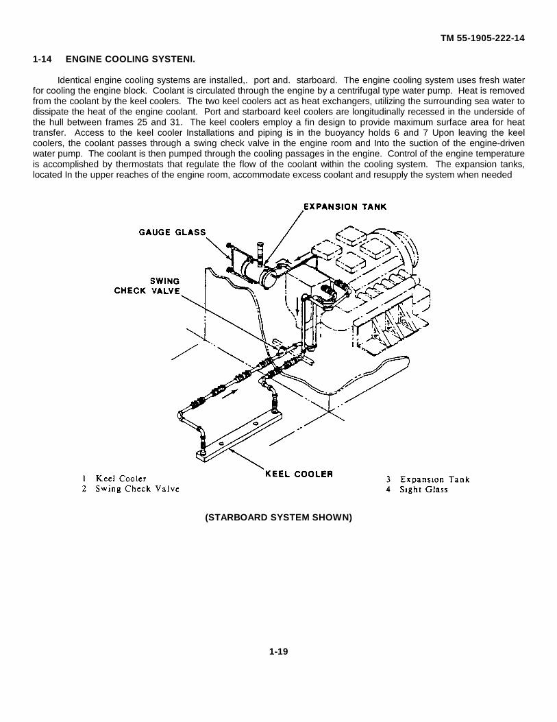
Identical engine cooling systems are installed,. port and. starboard. The engine cooling system uses fresh waterfor cooling the engine block. Coolant is circulated through the engine by a centrifugal type water pump. Heat is removedfrom the coolant by the keel coolers. The two keel coolers act as heat exchangers, utilizing the surrounding sea water todissipate the heat of the engine coolant. Port and starboard keel coolers are longitudinally recessed in the underside ofthe hull between frames 25 and 31. The keel coolers employ a fin design to provide maximum surface area for heattransfer. Access to the keel cooler Installations and piping is in the buoyancy holds 6 and 7 Upon leaving the keelcoolers, the coolant passes through a swing check valve in the engine room and Into the suction of the engine-drivenwater pump. The coolant is then pumped through the cooling passages in the engine. Control of the engine temperatureis accomplished by thermostats that regulate the flow of the coolant within the cooling system. The expansion tanks,located In the upper reaches of the engine room, accommodate excess coolant and resupply the system when needed
(STARBOARD SYSTEM SHOWN)
1-19
TM 55-1905-222-14
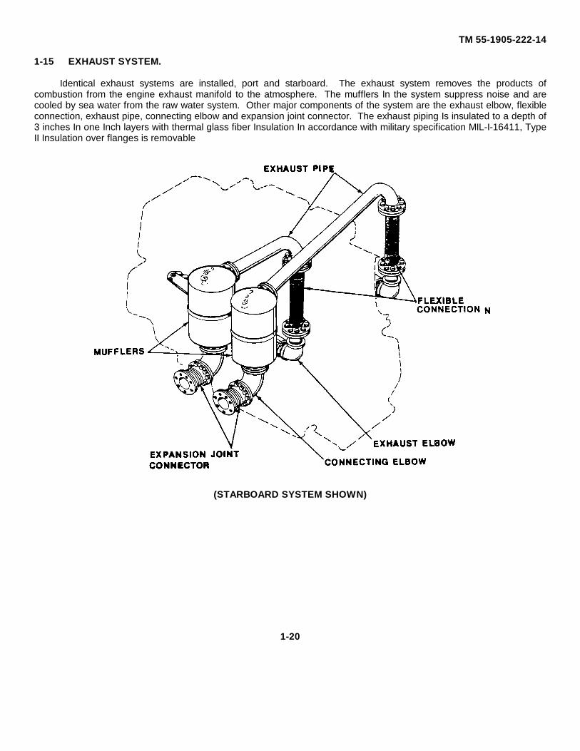
1-15 EXHAUST SYSTEM.
Identical exhaust systems are installed, port and starboard. The exhaust system removes the products ofcombustion from the engine exhaust manifold to the atmosphere. The mufflers In the system suppress noise and arecooled by sea water from the raw water system. Other major components of the system are the exhaust elbow, flexibleconnection, exhaust pipe, connecting elbow and expansion joint connector. The exhaust piping Is insulated to a depth of3 inches In one Inch layers with thermal glass fiber Insulation In accordance with military specification MIL-I-16411, TypeII Insulation over flanges is removable
(STARBOARD SYSTEM SHOWN)
1-20

TM 55-1905-222-14
1-16 RAW (SEA) WATER COOLING SYSTEM.
Identical raw water systems are installed, port and starboard. The function of the raw water cooling system is two-foldprovide cooling for the mufflers and the return fuel oil, and priming for the bilge pumps. Sea water Intake is at the seachest located aft of each marine transmission. The suction valves allow sea water to flow through the strainers mountedon each side of the engine room. The engine-mounted raw water pump pumps the sea water through the fuel oil coolersand the mufflers. The priming valve allows sea water priming of the bilge pump. Some sea water is dischargedoverboard through the discharge valve. The discharge valve is used to control the amount and rate at which sea waterpasses through the fuel oil coolers and mufflers. The sea water which is used to cool the mufflers is discharged throughthe exhaust ports with the exhaust gases
(STARBOARD SYSTEM SHOWN)
1-21
TM 55-1905-222-14
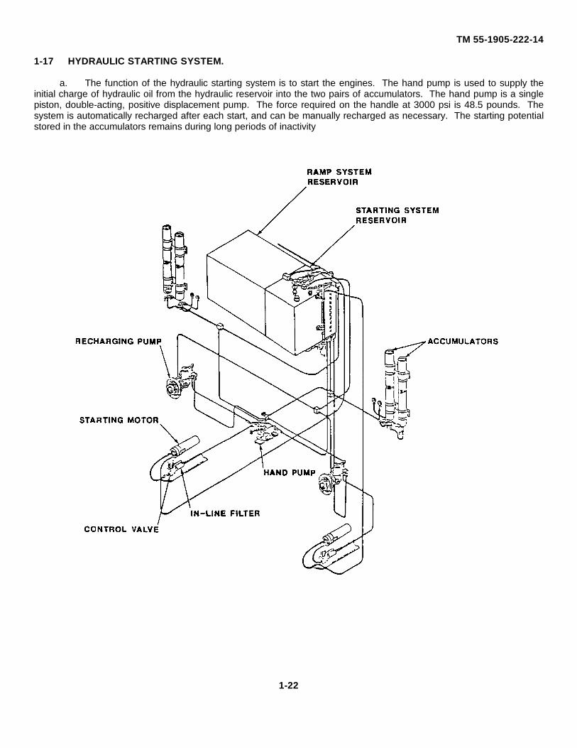
1-17 HYDRAULIC STARTING SYSTEM.
a. The function of the hydraulic starting system is to start the engines. The hand pump is used to supply theinitial charge of hydraulic oil from the hydraulic reservoir into the two pairs of accumulators. The hand pump is a singlepiston, double-acting, positive displacement pump. The force required on the handle at 3000 psi is 48.5 pounds. Thesystem is automatically recharged after each start, and can be manually recharged as necessary. The starting potentialstored in the accumulators remains during long periods of inactivity
1-22
TM 55-1905-222-14
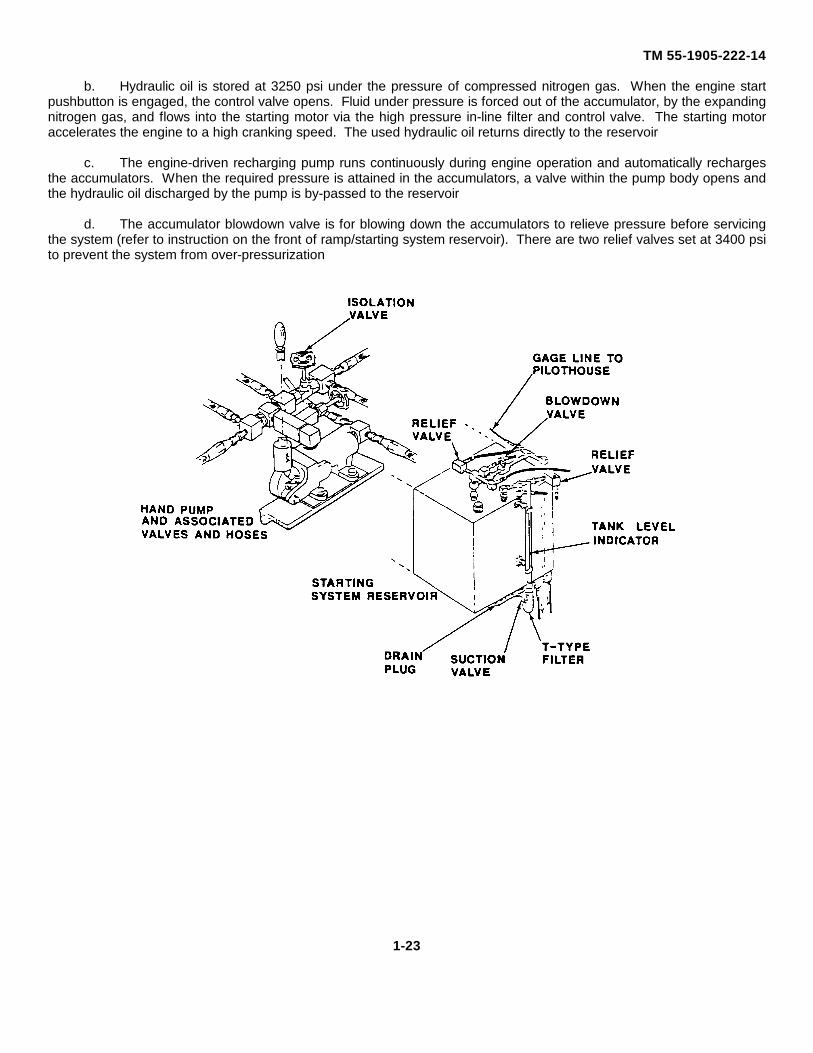
b. Hydraulic oil is stored at 3250 psi under the pressure of compressed nitrogen gas. When the engine startpushbutton is engaged, the control valve opens. Fluid under pressure is forced out of the accumulator, by the expandingnitrogen gas, and flows into the starting motor via the high pressure in-line filter and control valve. The starting motoraccelerates the engine to a high cranking speed. The used hydraulic oil returns directly to the reservoir
c. The engine-driven recharging pump runs continuously during engine operation and automatically rechargesthe accumulators. When the required pressure is attained in the accumulators, a valve within the pump body opens andthe hydraulic oil discharged by the pump is by-passed to the reservoir
d. The accumulator blowdown valve is for blowing down the accumulators to relieve pressure before servicingthe system (refer to instruction on the front of ramp/starting system reservoir). There are two relief valves set at 3400 psito prevent the system from over-pressurization
1-23
TM 55-1905-222-14
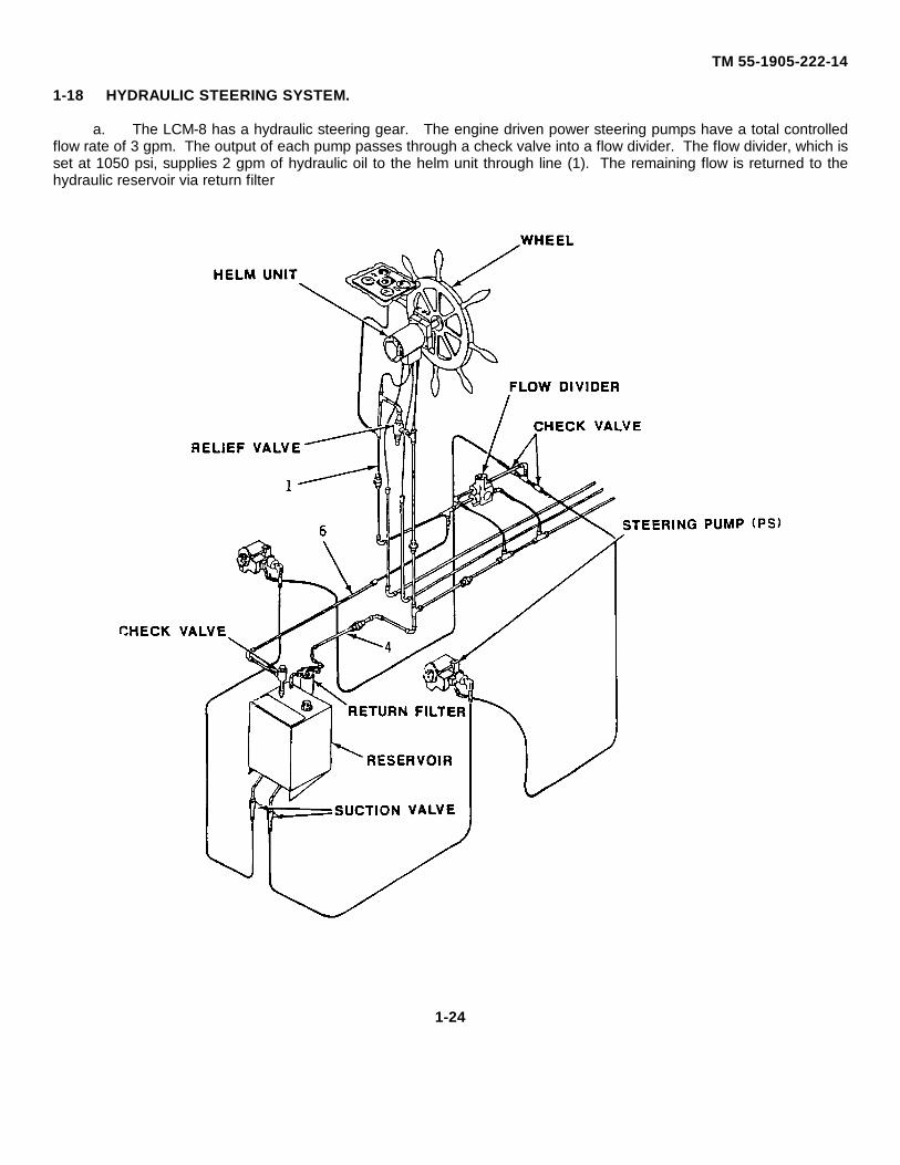
1-18 HYDRAULIC STEERING SYSTEM.
a. The LCM-8 has a hydraulic steering gear. The engine driven power steering pumps have a total controlledflow rate of 3 gpm. The output of each pump passes through a check valve into a flow divider. The flow divider, which isset at 1050 psi, supplies 2 gpm of hydraulic oil to the helm unit through line (1). The remaining flow is returned to thehydraulic reservoir via return filter
1-24
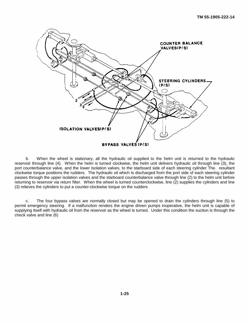
TM 55-1905-222-14
b. When the wheel is stationary, all the hydraulic oil supplied to the helm unit is returned to the hydraulicreservoir through line (4). When the helm is turned clockwise, the helm unit delivers hydraulic oil through line (3), theport counterbalance valve, and the lower Isolation valves, to the starboard side of each steering cylinder The. resultantclockwise torque positions the rudders. The hydraulic oil which Is discharged from the port side of each steering cylinderpasses through the upper isolation valves and the starboard counterbalance valve through line (2) to the helm unit beforereturning to reservoir via return filter. When the wheel is turned counterclockwise, line (2) supplies the cylinders and line(3) relieves the cylinders to put a counter-clockwise torque on the rudders
c. The four bypass valves are normally closed but may be opened to drain the cylinders through line (5) topermit emergency steering. If a malfunction renders the engine driven pumps inoperative, the helm unit is capable ofsupplying Itself with hydraulic oil from the reservoir as the wheel Is turned. Under this condition the suction is through thecheck valve and line (6)
1-25
TM 55-1905-222-14
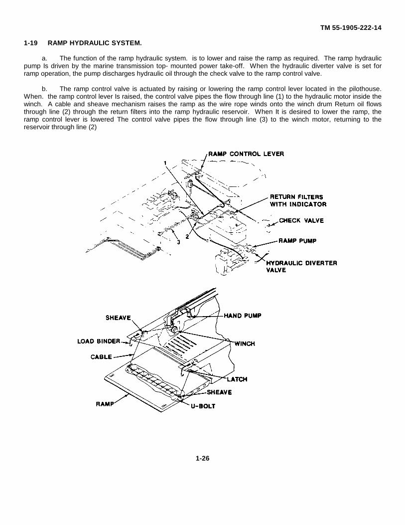
1-19 RAMP HYDRAULIC SYSTEM.
a. The function of the ramp hydraulic system. is to lower and raise the ramp as required. The ramp hydraulicpump Is driven by the marine transmission top- mounted power take-off. When the hydraulic diverter valve is set forramp operation, the pump discharges hydraulic oil through the check valve to the ramp control valve.
b. The ramp control valve is actuated by raising or lowering the ramp control lever located in the pilothouse.When. the ramp control lever Is raised, the control valve pipes the flow through line (1) to the hydraulic motor inside thewinch. A cable and sheave mechanism raises the ramp as the wire rope winds onto the winch drum Return oil flowsthrough line (2) through the return filters into the ramp hydraulic reservoir. When It is desired to lower the ramp, theramp control lever is lowered The control valve pipes the flow through line (3) to the winch motor, returning to thereservoir through line (2)
1-26
TM 55-1905-222-14
c. Emergency lowering of the ramp is accomplished by the use of a hydraulic hand pump. The emergencyramp hoisting device consists of two 3-ton chain fall hoists Each hoist consists of a reeving chain with swivel hook,selector lever, chain attachment, gear housing assembly and bottom hook
d. A hydraulically actuated mechanical latch is provided to secure the ramp in the fully raised position. Thelatch is unlocked by hydraulic pressure when the ramp control lever is placed In the RAMP DOWN position. The latch isautomatically locked when the ramp is raised. The latch can be unlocked during emergency conditions (no pressure Inthe ramp hydraulic system, engines not operating, etc) by operating the hand pump
e. The ramp winch Incorporates an automatic winch reversing mechanism. The mechanism, prevents cableoverrun and coiling when the ramp lowering cycle is completed or Interrupted. When the cable goes slack, themechanism. causes the hydraulic oil to bypass the winch and is returned to the reservoir
1-27
TM 55-1905-222-14
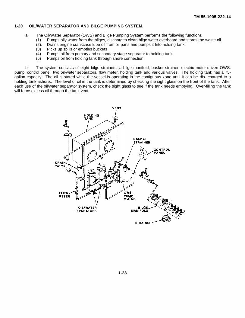
1-20 OIL/WATER SEPARATOR AND BILGE PUMPING SYSTEM.
a. The Oil/Water Separator (OWS) and Bilge Pumping System performs the following functions(1) Pumps oily water from the bilges, discharges clean bilge water overboard and stores the waste oil.(2). Drains engine crankcase lube oil from oil pans and pumps it Into holding tank(3) Picks up spills or empties buckets(4) Pumps oil from primary and secondary stage separator to holding tank(5) Pumps oil from holding tank through shore connection
b. The system consists of eight bilge strainers, a bilge manifold, basket strainer, electric motor-driven OWS.pump, control panel, two oil-water separators, flow meter, holding tank and various valves. The holding tank has a 75-gallon capacity. The oil is stored while the vessel is operating in the contiguous zone until It can be dis- charged to aholding tank ashore.. The level of oil in the tank is determined by checking the sight glass on the front of the tank. Aftereach use of the oil/water separator system, check the sight glass to see if the tank needs emptying. Over-filling the tankwill force excess oil through the tank vent.
1-28
TM 55-1905-222-14
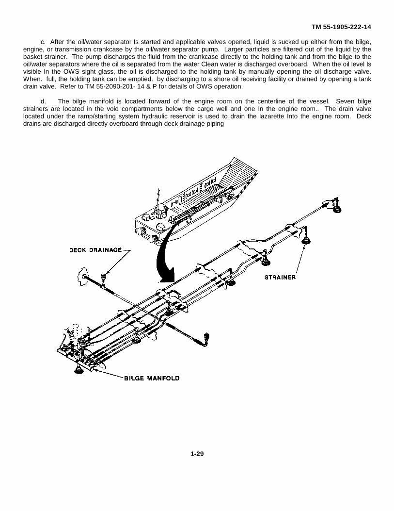
c. After the oil/water separator Is started and applicable valves opened, liquid is sucked up either from the bilge,engine, or transmission crankcase by the oil/water separator pump. Larger particles are filtered out of the liquid by thebasket strainer. The pump discharges the fluid from the crankcase directly to the holding tank and from the bilge to theoil/water separators where the oil is separated from the water Clean water is discharged overboard. When the oil level Isvisible In the OWS sight glass, the oil is discharged to the holding tank by manually opening the oil discharge valve.When. full, the holding tank can be emptied. by discharging to a shore oil receiving facility or drained by opening a tankdrain valve. Refer to TM 55-2090-201- 14 & P for details of OWS operation.
d. The bilge manifold is located forward of the engine room on the centerline of the vessel. Seven bilgestrainers are located in the void compartments below the cargo well and one In the engine room.. The drain valvelocated under the ramp/starting system hydraulic reservoir is used to drain the lazarette Into the engine room. Deckdrains are discharged directly overboard through deck drainage piping
1-29
TM 55-1905-222-14
1-21 EMERGENCY BILGE SYSTEM.
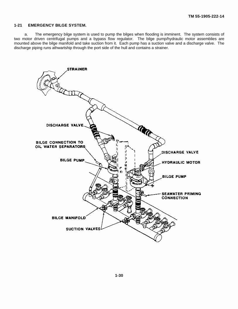
a. The emergency bilge system is used to pump the bilges when flooding is imminent. The system consists oftwo motor driven centrifugal pumps and a bypass flow regulator. The bilge pump/hydraulic motor assemblies aremounted above the bilge manifold and take suction from it. Each pump has a suction valve and a discharge valve. Thedischarge piping runs athwartship through the port side of the hull and contains a strainer.
1-30
TM 55-1905-222-14
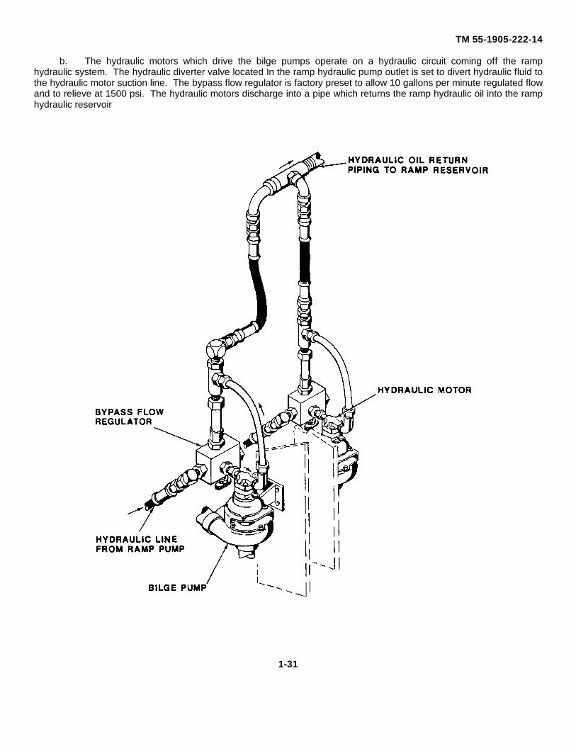
b. The hydraulic motors which drive the bilge pumps operate on a hydraulic circuit coming off the ramphydraulic system. The hydraulic diverter valve located In the ramp hydraulic pump outlet is set to divert hydraulic fluid tothe hydraulic motor suction line. The bypass flow regulator is factory preset to allow 10 gallons per minute regulated flowand to relieve at 1500 psi. The hydraulic motors discharge into a pipe which returns the ramp hydraulic oil into the ramphydraulic reservoir
1-31
TM 55-1905-222-14
1-22 ELECTRICAL SYSTEM
a. The electrical system is a 24 VDC two-wire ungrounded system. Normal source of electrical distribution forpower, lighting and IC (interior communication) systems circuits is supplied by two engine driven alternators. When theengines are shut down, electrical distribution for power, lighting and IC circuits is supplied from two 12 volt seriesconnected storage batteries.
b. The prime purpose of the batteries in the vessel's electrical system is to provide a source of electrical power forstarting the engines. (Note that the power is applied to the control valves for hydraulic starting and not directly to thestarting motors). The batteries also act as a stabilizer to the voltage in the electrical system. They can, for a limitedtime, furnish current when the electrical demands of the LCM-8 exceed the output of the alternator After the engines arerunning, the alternator is intended to supply all of the electrical requirements of the LCM-8, plus additional power toreplace the charge taken from the batteries to start the engines.
c. The belt-driven alternators convert mechanical and magnetic energy to alternating current (ac) and. voltageby the rotation of an electromagnetic field (rotor). The three phase, full wave rectifier system contained within thealternator converts the ac into direct current (dc). The six silicon rectifier diodes will pass current from the alternator tothe batteries or load, but will not pass current from the batteries to the alternator. Hence, no cut-out relay is required. Afuel pressure switch, installed In each engine fuel system, disconnects the alternator field when the engine is shut down.Each alternator assembly Includes a starting field resistor, a voltage regulator and a voltage protector. The function ofthe voltage regulator is to maintain constant system output voltage under all speeds and load conditions. This isnecessary because excessive voltage will damage electrical components and Instruments. The electronic voltageregulator functions like a solid state switch which constantly monitors system voltage. When the voltage tends to drop,the switch closes and energizes the alternator field winding to increase the output. When the system voltage tends torise, the regulator switch opens and de-energizes the field circuit to decrease the voltage. The voltage protector protectsthe alternator from high voltages under certain conditions. For instance, if the batteries are inadvertently disconnectedwhile the alternator is operating, unusually large output voltages could destroy the alternator
d. A control and distribution panel is provided to supply groups of loads located in close proximity to each other.The control and distribution panel is located. In the pilothouse Junction boxes are provided in the pilothouse, and stuffingtubes are used where cables pass through watertight bulkheads. A circuit breaker enclosure is installed on the engineroom aft bulkhead with a breaker designed to protect the battery or alternators against short circuit. A safety switch isalso Installed on the aft bulkhead to protect the IC circuits. Circuits supplied from the control and distribution panel areprotected by 10A and 20A. fuses. Refer to Foldout-3 for a schematic diagram of the electrical system.
e. Individual switches for fans, windshield wipers and engine room receptacles are located on the control anddistribution panel. The receptacle circuits are fuse protected. Two overhead white lights and eight overhead white lightsprovide illumination in the lazarette and engine room respectively. The marine sanitation device compartment has oneoverhead. white light. The stowage compartment has one over- head white light. Two bulkhead mounted red lights areinstalled In the cargo well, aft. Panel lighting is provided, port and starboard, for the pilothouse console instruments. Thelights are controlled by a DPDT switch on the control and distribution panel, and protected with a 10A fuse. Each lightgroup is controlled by a separate switch.
1-32
TM 55-1905-222-14
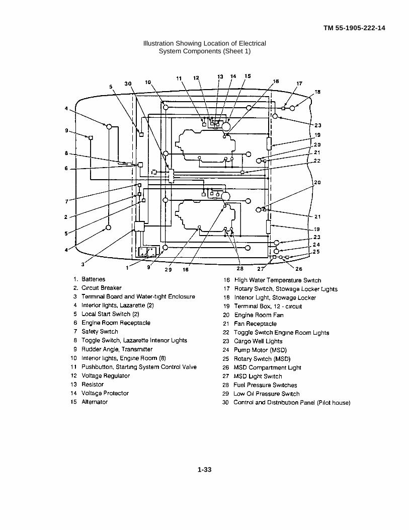
Illustration Showing Location of ElectricalSystem Components (Sheet 1)
1-33
TM 55-1905-222-14
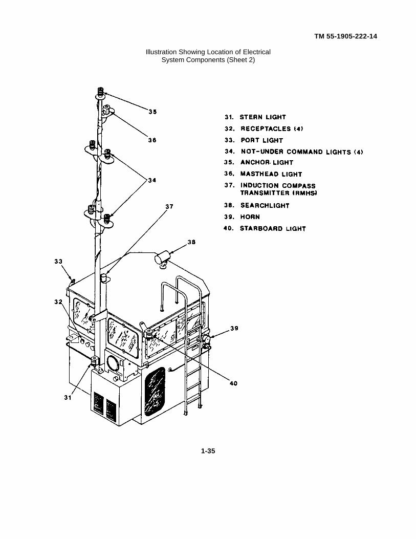
f. The navigation lights are controlled by a double pole, double throw switch (DPDT) located in the control anddistribution panel. A stern light, two side lights (port and starboard), four not-under-command lights, an anchor light andmasthead light comprise the navigation lights. These lighting circuits are protected by panel installed 10A fuses. Themasthead, anchor and not-under-command light-; are mounted on a telescoping mast hinge-mounted on deck aft of thepilothouse. The mast lighting circuits are completed through plugs and receptacles Installed on the aft side of thepilothouse. An induction compass transmitter for the RMHS is located on top of the mast support (see illustration onfacing page)
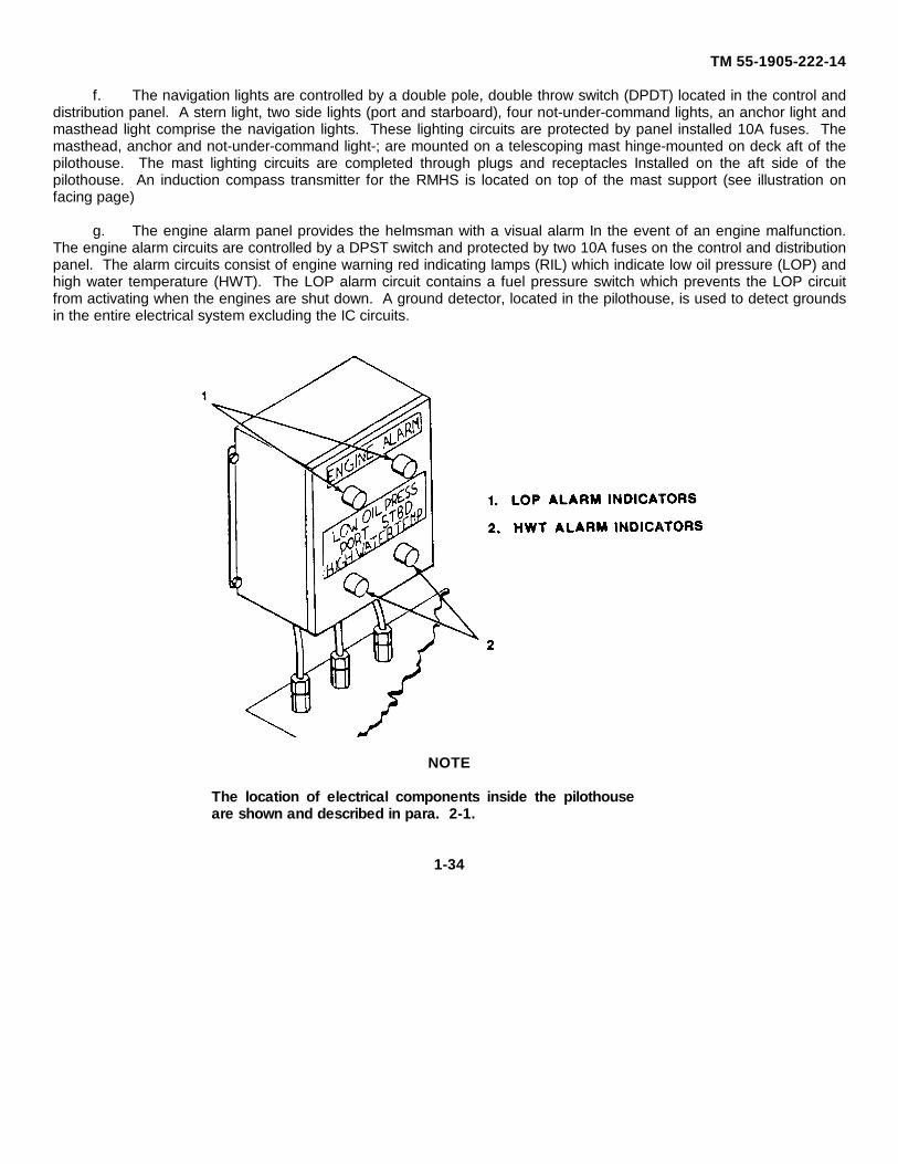
g. The engine alarm panel provides the helmsman with a visual alarm In the event of an engine malfunction.The engine alarm circuits are controlled by a DPST switch and protected by two 10A fuses on the control and distributionpanel. The alarm circuits consist of engine warning red indicating lamps (RIL) which indicate low oil pressure (LOP) andhigh water temperature (HWT). The LOP alarm circuit contains a fuel pressure switch which prevents the LOP circuitfrom activating when the engines are shut down. A ground detector, located in the pilothouse, is used to detect groundsin the entire electrical system excluding the IC circuits.
NOTE
The location of electrical components inside the pilothouseare shown and described in para. 2-1.
1-34
TM 55-1905-222-14
Illustration Showing Location of ElectricalSystem Components (Sheet 2)
1-35
TM 55-1905-222-14
1-23 MARINE SANITATION DEVICE.
1-23.1 System Description.
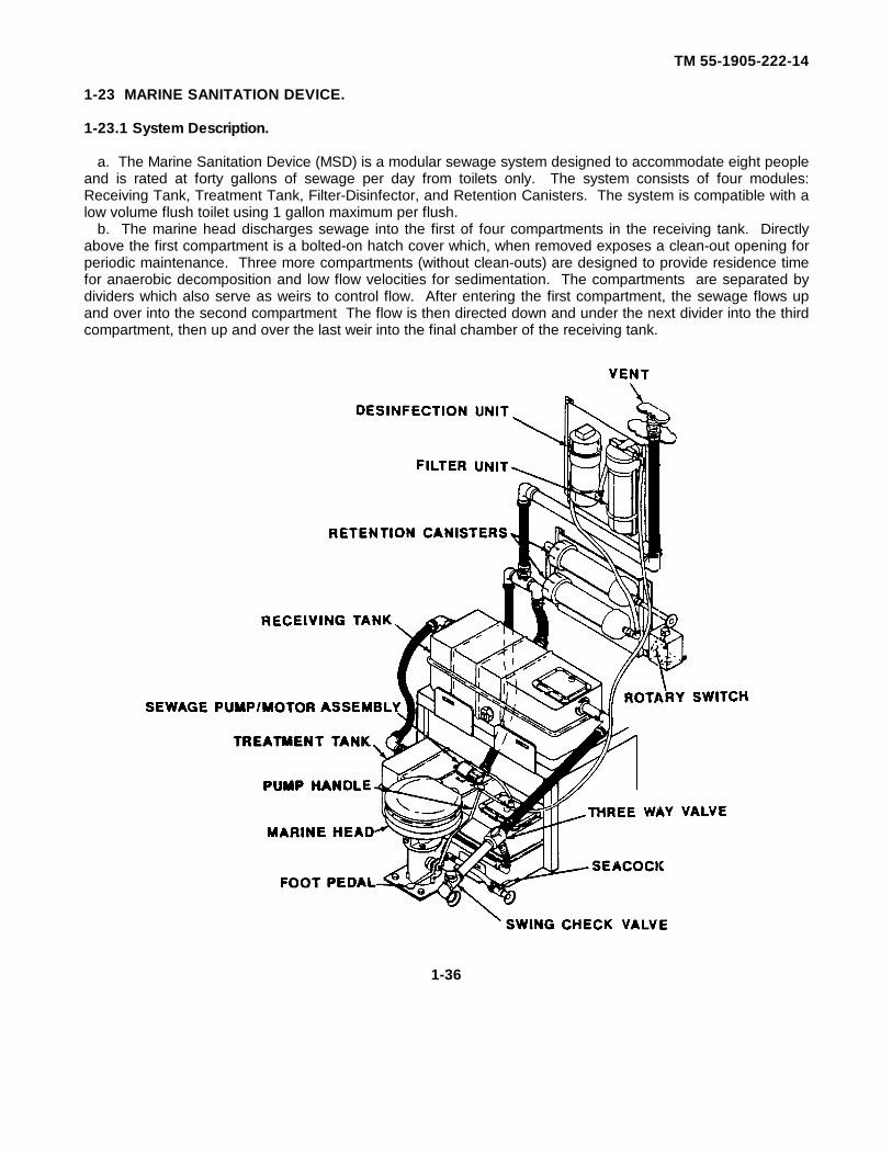
a. The Marine Sanitation Device (MSD) is a modular sewage system designed to accommodate eight peopleand is rated at forty gallons of sewage per day from toilets only. The system consists of four modules:Receiving Tank, Treatment Tank, Filter-Disinfector, and Retention Canisters. The system is compatible with alow volume flush toilet using 1 gallon maximum per flush.
b. The marine head discharges sewage into the first of four compartments in the receiving tank. Directlyabove the first compartment is a bolted-on hatch cover which, when removed exposes a clean-out opening forperiodic maintenance. Three more compartments (without clean-outs) are designed to provide residence timefor anaerobic decomposition and low flow velocities for sedimentation. The compartments are separated bydividers which also serve as weirs to control flow. After entering the first compartment, the sewage flows upand over into the second compartment The flow is then directed down and under the next divider into the thirdcompartment, then up and over the last weir into the final chamber of the receiving tank.
1-36
TM 55-1905-222-14
c. The sewage flows by gravity from the receiving tank into the first of four compartments in the treatmenttank. The sewage follows the same over and under flow path as In the receiving tank. The first threecompartments provide for further sedimentation and anaerobic decomposition before entering the finalchamber. An electric motor-pump installed on the treatment tank pumps the clarified effluent from the finalchamber to the filter-disinfector at a rate of 021 gpm. The pump is controlled by a float switch which isattached to the suction pipe and suspended from the hatch cover on the final chamber of the treatment tank.
d. The filter assembly is a standard water filter The filter housing can be unscrewed from the cap, permittingeasy replacement of the 50 micron filter element. The element can be washed and reused several times. Thesewage liquor is pumped through the filter element into the disinfection unit. The outlet of the filter has a built-in check valve to prevent backflow of liquid chlorine into the filter housing. The tablets of solid disinfectingagents inside the disinfector dissolve at a rate that provides for a three to six week period between rechargeoperations, depending on flow conditions. The maximum capacity is seven tablets.
e. The effluent flows by gravity from the disinfector into the retention canisters. The retention canistersprovide the proper residence time for oxidation of solid matter and disinfection of the liquid effluent. Theeffluent is discharged overboard from the retention canisters.
f. The marine head or "skipper" features a foot pedal and a smooth working easily accessible vertical pumphandle. The seacock allows sea water into the bowl when the foot pedal is engaged. The three-way valvepermits flushing the toilet through the MSD or directly overboard when the vessel is in the open sea. The swingcheck valve in the sewage discharge line prevents backflow.
g. The rotary switch is used to furnish electrical power to the pump motor to operate the marine sanitationdevice.
1-23.2 Treatment Method.
a. The sewage system uses a combination of sewage treatment principles to achieve a safe acceptableeffluent. The incoming sewage is subjected to sedimentation in the receiving and treatment tanks. While thesewage passes through these tanks it is subjected to a second treatment, natural decomposition by anaerobicaction. This natural action is accelerated by the addition of selected bacteria for use in the digestion andliquification of sewage. These enzymes reduce the complex fats, proteins and carbohydrates in the sewage tostable sludge through a chain of reactions. The bacteria supplements the action of the enzymes as well as toattack and liquify the fibrous components of raw sewage. The temperature at which the enzyme-bacterialaction Is most effective is 86F(30C).
b. The third treatment is a filtration stage consisting of final removal of all particles above 50 microns thathave passed through the preceding stages of treatment If the recommended flush water is exceeded, solids willnot be separated from the liquor and the filter will become clogged. The final stage of treatment consists ofchlorination which disinfects the effluent. The residence time in the retention canisters is approximately 5minutes. The oxidizing action of the chlorine solution not only results in elimination of pathogens but alsoreduces the biochemical oxygen demand (BOD) of the effluent.
1-37
TM 55-1905-222-14
Section IV. SERVICE UPON RECEIPT
1-24 GENERAL.
The services performed upon receipt of a new or used vessel are the responsibility of the receivingorganization and will be performed by the crew and issuing activity.
WARNING
Before volatile materials are brought aboard, or the engines arestarted, ensure that firefighting equipment is immediatelyavailable for use in case of fire emergency. Failure to complycould endanger personnel and/equipment.
1-25 INSPECTING AND SERVICING THE LCM-8.
The crew and issuing activity will conduct a 100 percent inventory of the vessel and required components asper appendices 'C" and 'D”. Any shortages will be listed and reported to the proper authority for correctiveaction. The crew will perform all of the operator PMCS as listed in paragraph 2-2. All defects and shortageswill be recorded on DA Form 2404 as per DA PAM 738-750. Upon inspection of vessel, all services up to andincluding those done annually, will be performed as listed in paragraph 4-4.
1-26 USED EQUIPMENT.
A vessel received from storage will be inspected as specified in paragraph 1-25 above. However, storagepersonnel will have performed the depreservation operation and outfitted and operated the vessel prior to thearrival of the crew.
1-38
TM 55-1905-222-14
CHAPTER 2OPERATING INSTRUCTIONS
Paragraph
Cold Weather Operation ................................................................................................ 2-6
Controls and Indicators................................................................................................... 2-1
Emergency Procedures.................................................................................................. 2-9
Foul Weather Operation................................................................................................. 2-8
Hot Weather Operation .................................................................................................. 2-7
Operating Procedure...................................................................................................... 2-4
Operation of Auxiliary Equipment................................................................................... 2-5
Pre-operating Procedures............................................................................................... 2-3
Preventive Maintenance................................................................................................. 2-2
2-1
TM 55-1905-222-14
Section I. DESCRIPTION AND USE OF OPERATOR CONTROLSAND INDICATORS
2-1 CONTROLS AND INDICATORS.
This paragraph contains a functional explanation of all operator controls and indicators (refer to table below).
Operator Controls and Indicators.
Key Control or Indicator Function
1. Communication Cabinet Contains three radio receiver - transmittersAN/VRC-47, AN/URC-92 and AN/URC-80.
2. ENGINE ALARMS Indicates when engine has low oil pressureand/high water temperature.
3. RUNNING LIGHTS Switch Turns the port, stern, starboard and not-under-command lights on and off.
4. MASTHEAD/ANCHOR LIGHTS Turns masthead and anchor lights on andSwitch off.
5. CARGO WELL LIGHTS Switch Turns cargo well lights on and off.
6. INSTRUMENT LIGHTS Switch Turns the instrument panel lights on and off.
7. Loudspeaker Used for voice communication with the AN/URC-80 radio.
8. Radio Control Box Used to select channel on the AN/URC-80 Radiofor ship to ship communication.
9. Windshield Wiper Switch Turns windshield wipers on and off.
10. Searchlight Receptacle Used to connect/disconnect power to thesearchlight.
11. Wiper Receptacle Used to connect/disconnect power to thewindshield wipers
12. Control Console Lights Illuminates the control console in the pilothouse.
13. Steering Wheel Used to change course of the craft.
14. Ramp Control Lever Used to raise or lower the ramp.
2-2
TM 55-1905-222-14
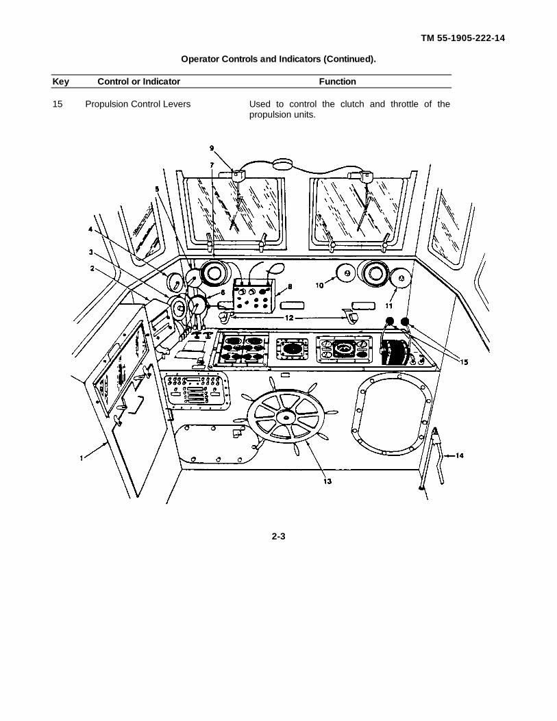
Operator Controls and Indicators (Continued).
Key Control or Indicator Function
15 Propulsion Control Levers Used to control the clutch and throttle of thepropulsion units.
2-3
TM 55-1905-222-14
Operator Controls and Indicators (Continued).
Key Control or Indicator Function
16. ENG SHUTDOWN Controls Used to stop the propulsion engines by cutting offfuel supply.
17. HYD STEERING Indicates the hydraulic pressure in thePressure Gauge steering system.
18. HYD RAMP Pressure Gauge Indicates the hydraulic pressure in the ramphydraulic system.
19. BATT AMPS Indicator Indicates the battery charge/discharge rate.
20. RUDDER ANGLE Indicator Indicates the position of the rudders.
21. HYD START Pressure Gauge Indicates the hydraulic pressure in the startingsystem.
22. COMPASS (RMHS) Indicates the heading of the vessel asdetermined by the induction compass transmitter.
23. Tachometer Indicates engine speed in revolutions per minute.
24. Alternator Ammeter Registers the current flow from the alternators.
25. TRANS OIL PRESS Gauge Registers the pressure of the lubricating oilfeeding the transmission.
26. ENG OIL PRESS Gauge Registers the pressure of the lubricating oil in theengine.
27. Water Temp Gauge Registers the temperature of the fresh waterused in the engine for cooling.
28. EMERGENCY ENGINE Used to stop the propulsion engines inSHUTDOWN Controls an emergency by cutting off the air supply.
29. HORN Button Used to sound the horn.
2-4

TM 55-1905-222-14
2-5
TM 55-1905-222-14
Operator Controls and Indicators (Continued).
Key Control or Indicator Function
30. ENG ALARM Switch Controls electrical power to the engine alarmpanel.
31. INSTR & WELL Switch Controls electrical power to the instrument panellights and cargo well lights
32. START STBD ENG Button Used to start the starboard propulsion engine byopening the starting system control valve.
33. ENG ROOM/STWG LKR Controls electrical power to the engine LTSSwitch room and stowage locker lights.
34. SEARCH LT Switch Controls electrical power to the search-light.
35. NAV LT Switch Controls electrical power to the navigation lights.
36. START PORT ENG Button Used to start the port propulsion engine byopening the starting system control valve.
37. LAZ & ENG RM Switch Controls electrical power to lazarette lights andengine room fans.
38. RMHS Switch Controls electrical power to the Remote MagneticHeading System.
39. WIPER RECP Switch Controls electrical power to the wiper receptacle.
40. RAI Switch Used to turn on/off power to the Rudder AngleIndicator.
2-6

TM 55-1905-222-14
2-7
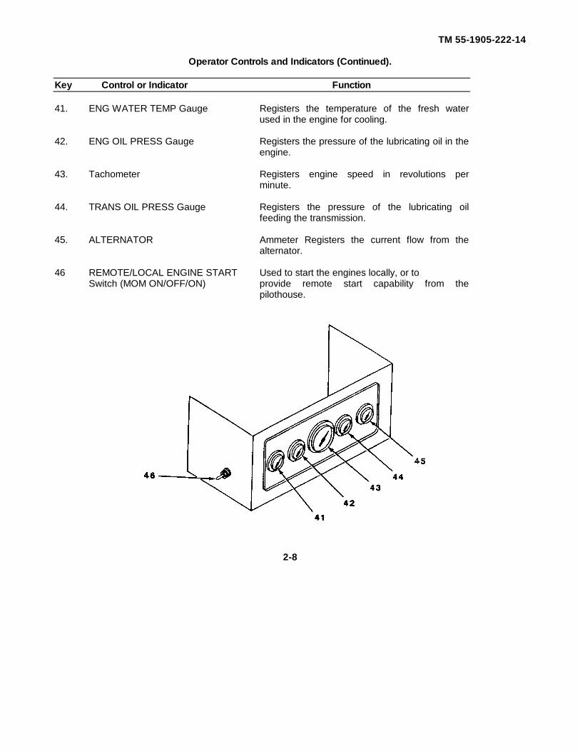
TM 55-1905-222-14
Operator Controls and Indicators (Continued).
Key Control or Indicator Function
41. ENG WATER TEMP Gauge Registers the temperature of the fresh waterused in the engine for cooling.
42. ENG OIL PRESS Gauge Registers the pressure of the lubricating oil in theengine.
43. Tachometer Registers engine speed in revolutions perminute.
44. TRANS OIL PRESS Gauge Registers the pressure of the lubricating oilfeeding the transmission.
45. ALTERNATOR Ammeter Registers the current flow from thealternator.
46 REMOTE/LOCAL ENGINE START Used to start the engines locally, or toSwitch (MOM ON/OFF/ON) provide remote start capability from the
pilothouse.
2-8

TM 55-1905-222-14
Operator Controls and Indicators (Continued).
Key Control or Indicator Function
47. Control Valve Pushbutton Used to start the engines as a manual overridemode.
48. Starting System Hand Pump Used to provide initial charge to theaccumulators for starting the engines.
2-9
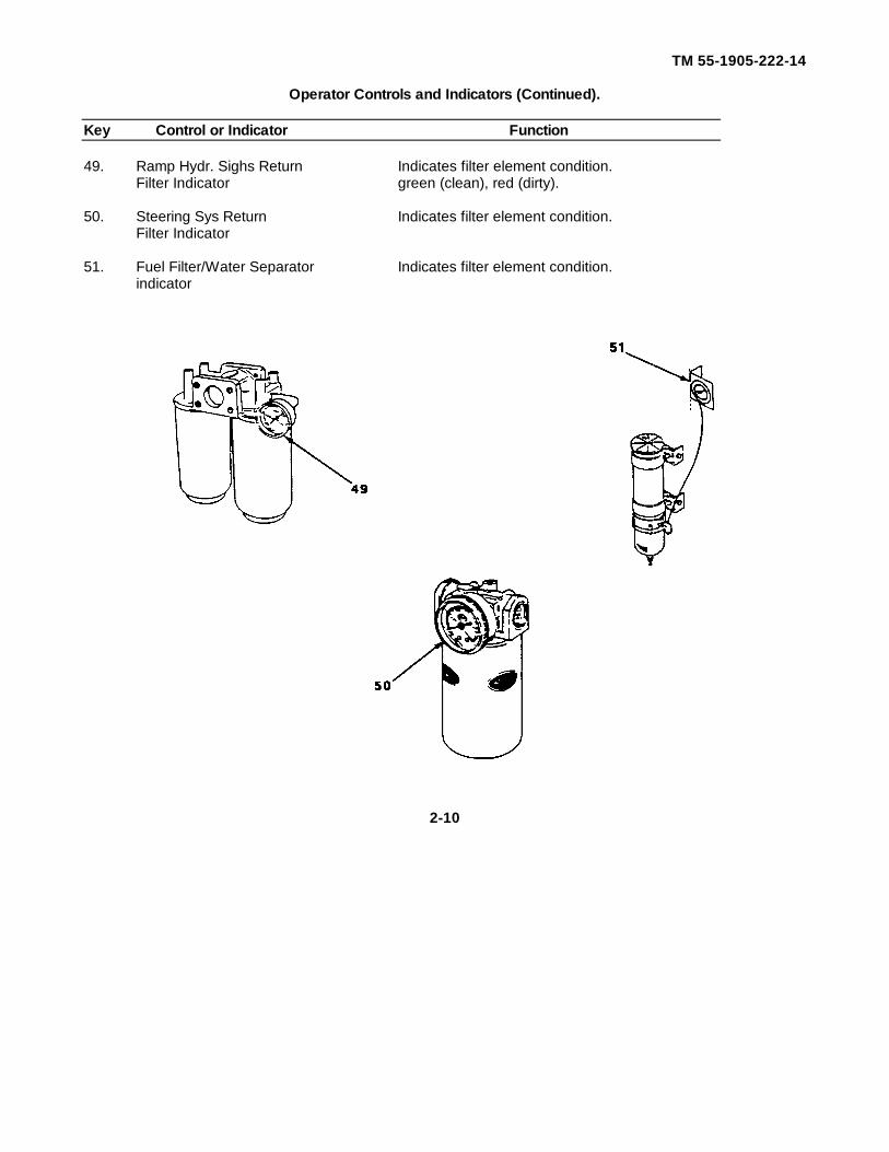
TM 55-1905-222-14
Operator Controls and Indicators (Continued).
Key Control or Indicator Function
49. Ramp Hydr. Sighs Return Indicates filter element condition.Filter Indicator green (clean), red (dirty).
50. Steering Sys Return Indicates filter element condition.Filter Indicator
51. Fuel Filter/Water Separator Indicates filter element condition.indicator
2-10
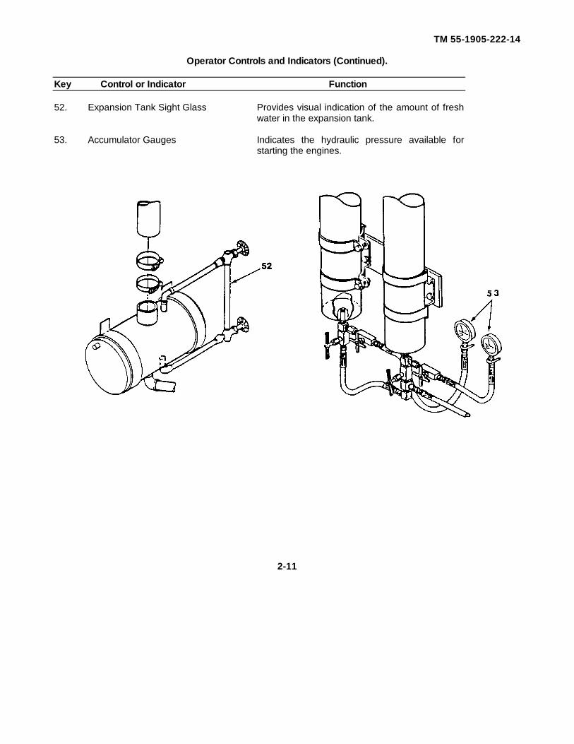
TM 55-1905-222-14
Operator Controls and Indicators (Continued).
Key Control or Indicator Function
52. Expansion Tank Sight Glass Provides visual indication of the amount of freshwater in the expansion tank.
53. Accumulator Gauges Indicates the hydraulic pressure available forstarting the engines.
2-11
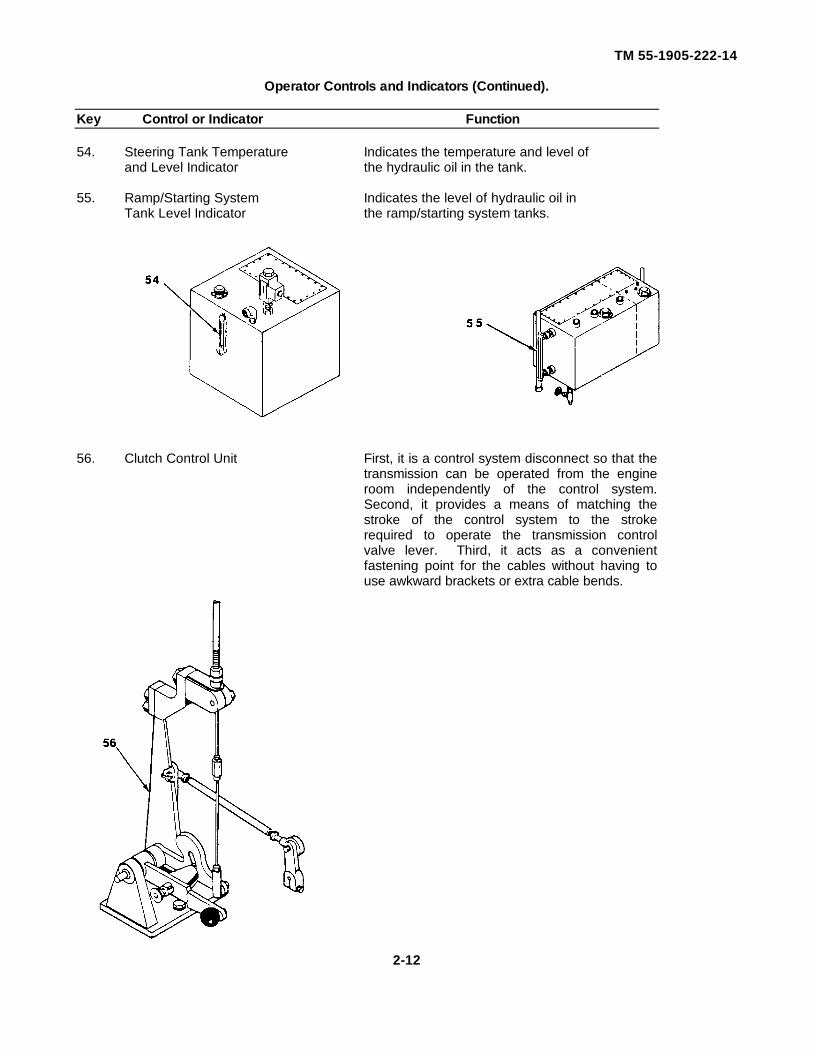
TM 55-1905-222-14
Operator Controls and Indicators (Continued).
Key Control or Indicator Function
54. Steering Tank Temperature Indicates the temperature and level ofand Level Indicator the hydraulic oil in the tank.
55. Ramp/Starting System Indicates the level of hydraulic oil inTank Level Indicator the ramp/starting system tanks.
56. Clutch Control Unit First, it is a control system disconnect so that thetransmission can be operated from the engineroom independently of the control system.Second, it provides a means of matching thestroke of the control system to the strokerequired to operate the transmission controlvalve lever. Third, it acts as a convenientfastening point for the cables without having touse awkward brackets or extra cable bends.
2-12
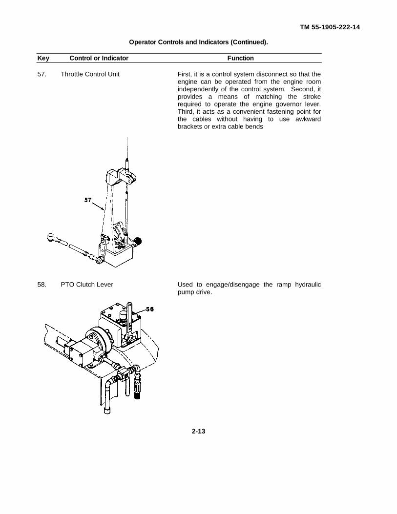
TM 55-1905-222-14
Operator Controls and Indicators (Continued).
Key Control or Indicator Function
57. Throttle Control Unit First, it is a control system disconnect so that theengine can be operated from the engine roomindependently of the control system. Second, itprovides a means of matching the strokerequired to operate the engine governor lever.Third, it acts as a convenient fastening point forthe cables without having to use awkwardbrackets or extra cable bends
58. PTO Clutch Lever Used to engage/disengage the ramp hydraulicpump drive.
2-13
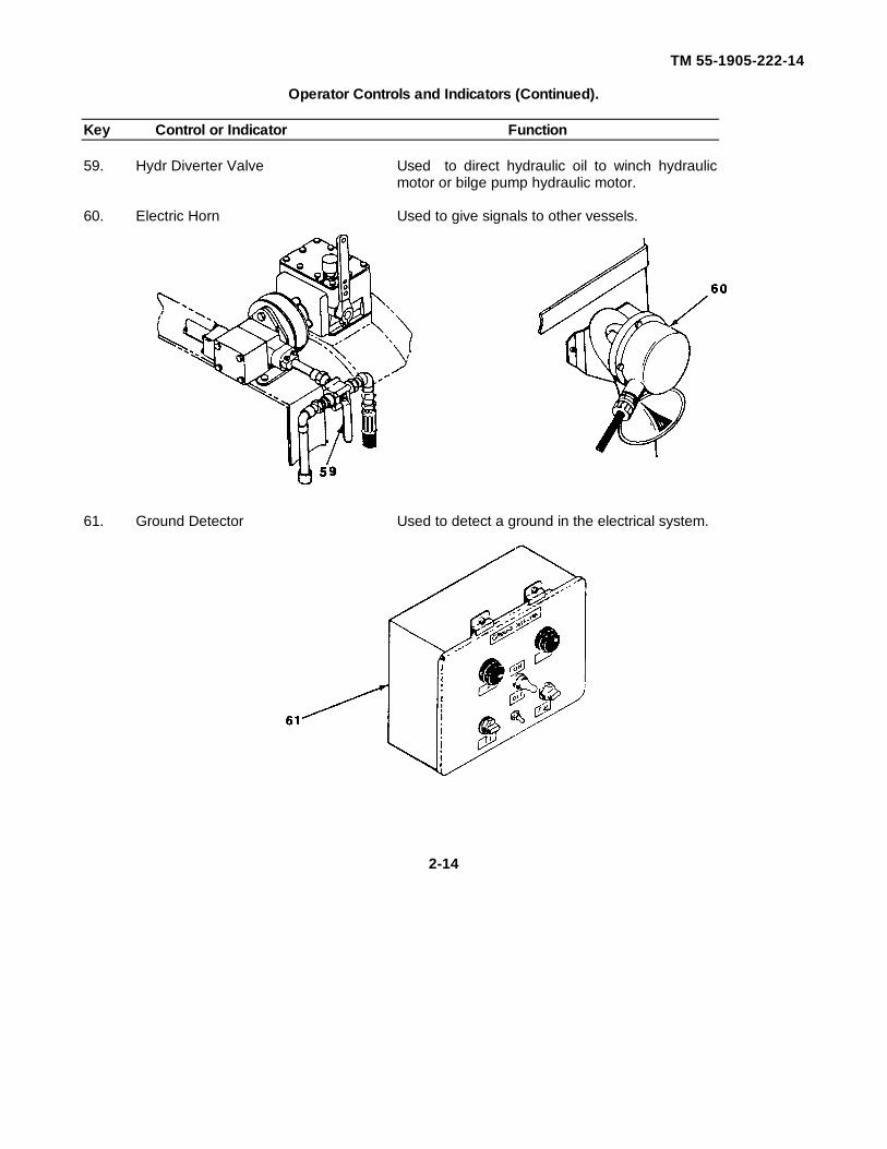
TM 55-1905-222-14
Operator Controls and Indicators (Continued).
Key Control or Indicator Function
59. Hydr Diverter Valve Used to direct hydraulic oil to winch hydraulicmotor or bilge pump hydraulic motor.
60. Electric Horn Used to give signals to other vessels.
61. Ground Detector Used to detect a ground in the electrical system.
2-14
TM 55-1905-222-14
Section II. OPERATOR PREVENTIVE MAINTENANCECHECKS AND SERVICES
2-2 PREVENTIVE MAINTENANCE.
2-2.1 General. Preventive Maintenance (PM) is the systematic care, servicing and inspection of equipmentThe purpose of PM is to keep the LCM-8 In serviceable condition, and to prevent, find and repair conditionsthat could render the equipment Inoperable Deficiencies noted that are above the crew level of maintenanceshould be reported to Unit level utilizing DA Form 2404 (Material Inspection Report) In accordance with DAPAM 738-750
a. Before you operate. Always keep in mind the cautions and warnings Perform your before (B)operation PMCS.
b. While you operate. Always keep in mind the cautions and warnings. Perform your during (D)operation PMCS.
c. After you operate. Be sure to perform your after (A) operation PMCS.d. If your equipment fails to operate. Troubleshoot with proper equipment. Report any deficiencies
using the appropriate forms See DA PAM 738-750.
2-2.2 PMCS Procedures.
a. Your Preventive Maintenance Checks and Services table lists the inspections and care of your LCM-8required to keep it in good operating condition.
b. The Interval column of your PMCS table tells you when to do a certain check or service.c. Leakage definitions for operator/crew PMCS are classified as follows:
Class I Seepage of fluid (as indicated by wetness or discoloration) not great enough to formdrops.
Class II Leakage of fluid great enough to form drops but not enough to cause drops to drip fromitem being checked/inspected.
Class III Leakage of fluid great enough to form drops that fall from the item beingchecked/inspected.
CAUTION
· Equipment operation is allowable with minor leakages (Class I or II).Of course, you must consider the fluid capacity in the item/systembeing checked/inspected. When in doubt notify your supervisor.
· When operating with Class I or Class II leaks, continue to check fluid
levels as required in your PMCS. · Class III leaks should be reported to your supervisor or
organizational maintenance.
2-15
TM 55-1905-222-14
d. “Before Operation" checks are limited to those required for consecutive application by an assignedoperator/crew. The following instructions should be observed to obtain Increased inspections when theLCM-8 is first assigned to an operator/crew or when operation is resumed after a period of nonuse.
Perform weekly as well as before operations PMCS as listed in table if:
a. You are the assigned operator and have not operated the LCM-8 since the last weeklyinspection.
b. You are operating the Item for the first time.
e. The procedure column of your PMCS table tells you how to do the required checks and services.Carefully follow these instructions If you do not have the tools, or if the procedure tells you to, haveorganizational maintenance do the work
f. If your equipment does not perform as required, refer to Chapter 3 under Troubleshooting for possibleproblems Report any malfunctions or failures on DA Form 2404 or refer to DA PAM 738-750
g. If your equipment requires removal in order to perform PMCS, refer to Chapter 3 under Maintenanceinstructions or notify your supervisor
2-2 3 Equipment is not ready/available if: procedures.
This column tells you when and why your equipment cannot be used.
NOTE
The terms "ready/available" and "mission capable" refer to the samestatus: Equipment is on hand and is able to perform its combatmissions (See DA PAM 738-750).
2-16
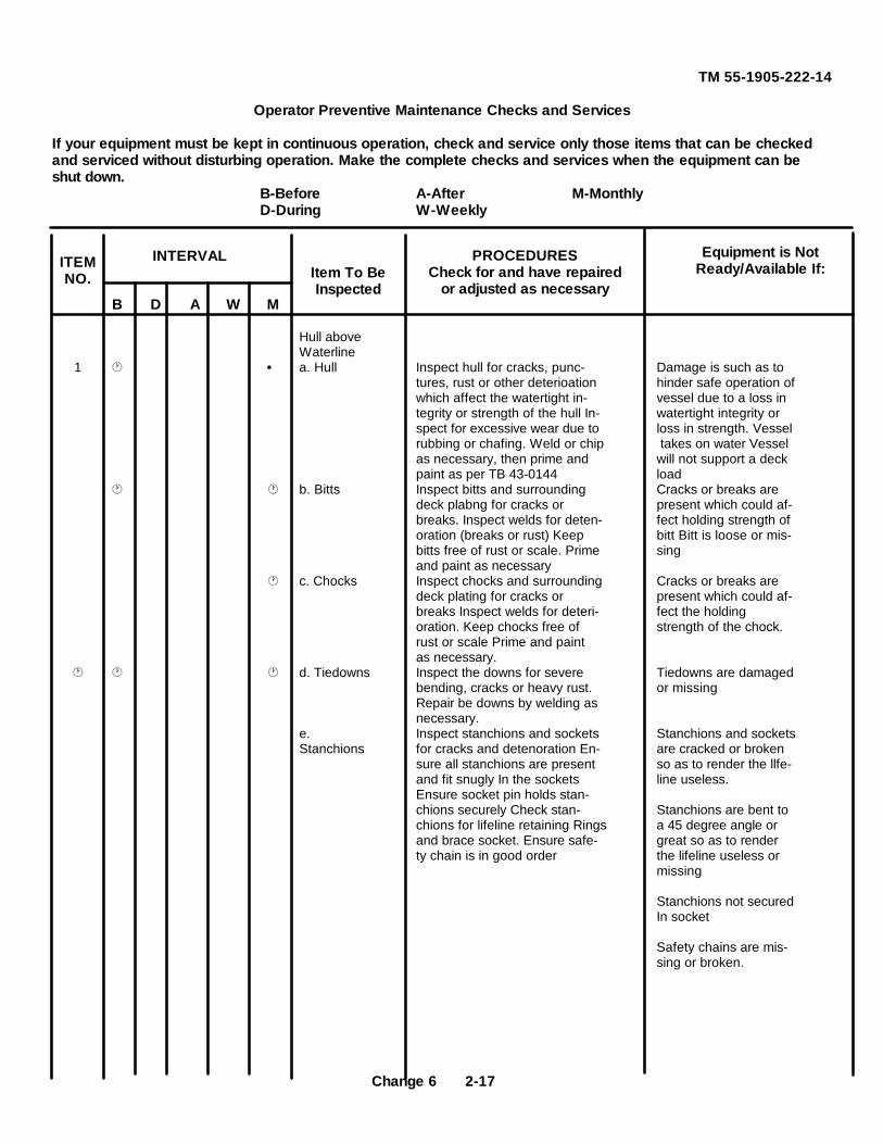
TM 55-1905-222-14
Operator Preventive Maintenance Checks and Services
If your equipment must be kept in continuous operation, check and service only those items that can be checkedand serviced without disturbing operation. Make the complete checks and services when the equipment can beshut down.
B-Before A-After M-MonthlyD-During W-Weekly
B D A W M
Hull aboveWaterline
1 · a. Hull Inspect hull for cracks, punc- Damage is such as totures, rust or other deterioation hinder safe operation ofwhich affect the watertight in- vessel due to a loss integrity or strength of the hull In- watertight integrity orspect for excessive wear due to loss in strength. Vesselrubbing or chafing. Weld or chip takes on water Vesselas necessary, then prime and will not support a deckpaint as per TB 43-0144 load
b. Bitts Inspect bitts and surrounding Cracks or breaks aredeck plabng for cracks or present which could af-breaks. Inspect welds for deten- fect holding strength oforation (breaks or rust) Keep bitt Bitt is loose or mis-bitts free of rust or scale. Prime singand paint as necessary
c. Chocks Inspect chocks and surrounding Cracks or breaks aredeck plating for cracks or present which could af-breaks Inspect welds for deteri- fect the holdingoration. Keep chocks free of strength of the chock.rust or scale Prime and paintas necessary.
d. Tiedowns Inspect the downs for severe Tiedowns are damagedbending, cracks or heavy rust. or missingRepair be downs by welding asnecessary.
e. Inspect stanchions and sockets Stanchions and socketsStanchions for cracks and detenoration En- are cracked or broken
sure all stanchions are present so as to render the llfe-and fit snugly In the sockets line useless.Ensure socket pin holds stan-chions securely Check stan- Stanchions are bent tochions for lifeline retaining Rings a 45 degree angle orand brace socket. Ensure safe- great so as to renderty chain is in good order the lifeline useless or
missing
Stanchions not securedIn socket
Safety chains are mis-sing or broken.
Item To BeInspected
Equipment is NotReady/Available If:
INTERVALITEMNO.
PROCEDURESCheck for and have repaired
or adjusted as necessary
Change 6 2-17
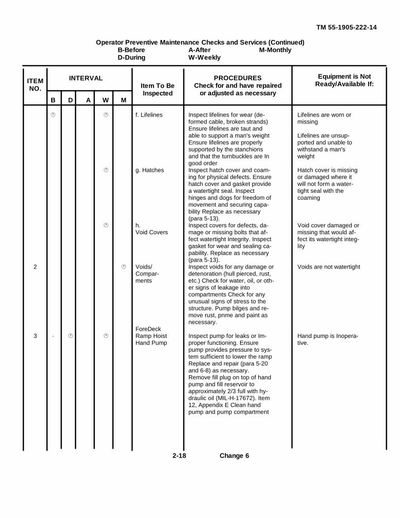
TM 55-1905-222-14
Operator Preventive Maintenance Checks and Services (Continued)B-Before A-After M-MonthlyD-During W-Weekly
B D A W M
f. Lifelines Inspect lifelines for wear (de- Lifelines are worn orformed cable, broken strands) missingEnsure lifelines are taut andable to support a man's weight Lifelines are unsup-Ensure lifelines are properly ported and unable tosupported by the stanchions withstand a man'sand that the turnbuckles are In weightgood order
g. Hatches Inspect hatch cover and coam- Hatch cover is missinging for physical defects. Ensure or damaged where ithatch cover and gasket provide will not form a water-a watertight seal. Inspect tight seal with thehinges and dogs for freedom of coamingmovement and securing capa-bility Replace as necessary(para 5-13).
h. Inspect covers for defects, da- Void cover damaged orVoid Covers mage or missing bolts that af- missing that would af-
fect watertight Integrity. Inspect fect its watertight integ-gasket for wear and sealing ca- litypability. Replace as necessary(para 5-13).
2 Voids/ Inspect voids for any damage or Voids are not watertightCompar- detenoration (hull pierced, rust,ments etc.) Check for water, oil, or oth-
er signs of leakage intocompartments Check for anyunusual signs of stress to thestructure. Pump bilges and re-move rust, pnme and paint asnecessary.
ForeDeck3 · Ramp Hoist Inspect pump for leaks or Im- Hand pump is Inopera-
Hand Pump proper functioning. Ensure tive.pump provides pressure to sys-tem sufficient to lower the rampReplace and repair (para 5-20and 6-8) as necessary.Remove fill plug on top of handpump and fill reservoir toapproximately 2/3 full with hy-draulic oil (MIL-H-17672). Item12, Appendix E Clean handpump and pump compartment
Item To BeInspected
Equipment is NotReady/Available If:
INTERVALITEMNO.
PROCEDURESCheck for and have repaired
or adjusted as necessary
2-18 Change 6
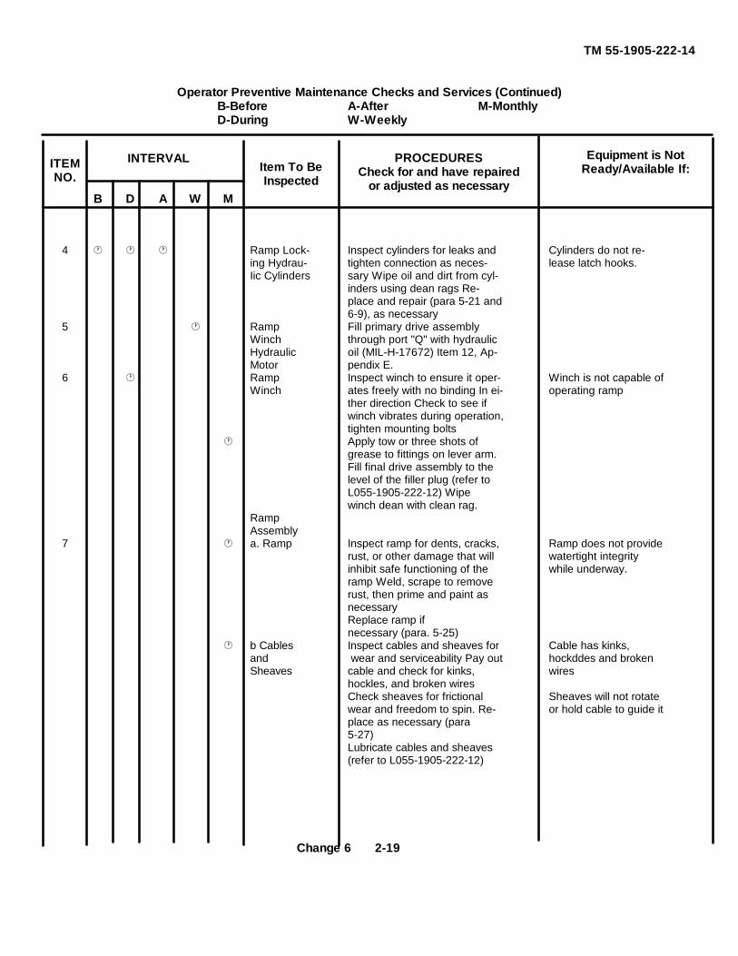
TM 55-1905-222-14
Operator Preventive Maintenance Checks and Services (Continued)B-Before A-After M-MonthlyD-During W-Weekly
B D A W M
4 Ramp Lock- Inspect cylinders for leaks and Cylinders do not re-ing Hydrau- tighten connection as neces- lease latch hooks.Iic Cylinders sary Wipe oil and dirt from cyl-
inders using dean rags Re-place and repair (para 5-21 and6-9), as necessary
5 Ramp Fill primary drive assemblyWinch through port "Q" with hydraulicHydraulic oil (MIL-H-17672) Item 12, Ap-Motor pendix E.
6 Ramp Inspect winch to ensure it oper- Winch is not capable ofWinch ates freely with no binding In ei- operating ramp
ther direction Check to see ifwinch vibrates during operation,tighten mounting bolts
Apply tow or three shots ofgrease to fittings on lever arm.Fill final drive assembly to thelevel of the filler plug (refer toL055-1905-222-12) Wipewinch dean with clean rag.
RampAssembly
7 a. Ramp Inspect ramp for dents, cracks, Ramp does not providerust, or other damage that will watertight integrityinhibit safe functioning of the while underway.ramp Weld, scrape to removerust, then prime and paint asnecessaryReplace ramp ifnecessary (para. 5-25)
b Cables Inspect cables and sheaves for Cable has kinks,and wear and serviceability Pay out hockddes and brokenSheaves cable and check for kinks, wires
hockles, and broken wiresCheck sheaves for frictional Sheaves will not rotatewear and freedom to spin. Re- or hold cable to guide itplace as necessary (para5-27)Lubricate cables and sheaves(refer to L055-1905-222-12)
Item To BeInspected
Equipment is NotReady/Available If:
INTERVALITEMNO.
PROCEDURESCheck for and have repaired
or adjusted as necessary
Change 6 2-19
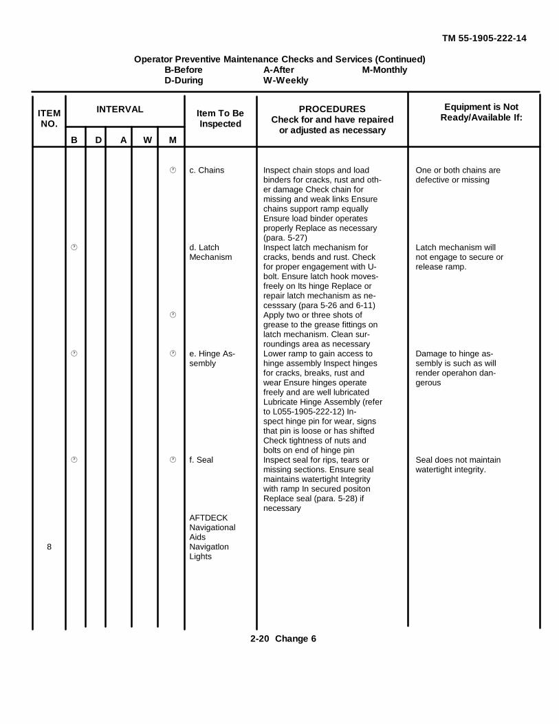
TM 55-1905-222-14
Operator Preventive Maintenance Checks and Services (Continued)B-Before A-After M-MonthlyD-During W-Weekly
B D A W M
c. Chains Inspect chain stops and load One or both chains arebinders for cracks, rust and oth- defective or missinger damage Check chain formissing and weak links Ensurechains support ramp equallyEnsure load binder operatesproperly Replace as necessary(para. 5-27)
d. Latch Inspect latch mechanism for Latch mechanism willMechanism cracks, bends and rust. Check not engage to secure or
for proper engagement with U- release ramp.bolt. Ensure latch hook moves-freely on Its hinge Replace orrepair latch mechanism as ne-cesssary (para 5-26 and 6-11)
Apply two or three shots ofgrease to the grease fittings onlatch mechanism. Clean sur-roundings area as necessary
e. Hinge As- Lower ramp to gain access to Damage to hinge as-sembly hinge assembly Inspect hinges sembly is such as will
for cracks, breaks, rust and render operahon dan-wear Ensure hinges operate gerousfreely and are well lubricatedLubricate Hinge Assembly (referto L055-1905-222-12) In-spect hinge pin for wear, signsthat pin is loose or has shiftedCheck tightness of nuts andbolts on end of hinge pin
f. Seal Inspect seal for rips, tears or Seal does not maintainmissing sections. Ensure seal watertight integrity.maintains watertight Integritywith ramp In secured positonReplace seal (para. 5-28) ifnecessary
AFTDECKNavigationalAids
8 NavigatlonLights
Item To BeInspected
Equipment is NotReady/Available If:
INTERVALITEMNO.
PROCEDURESCheck for and have repaired
or adjusted as necessary
2-20 Change 6
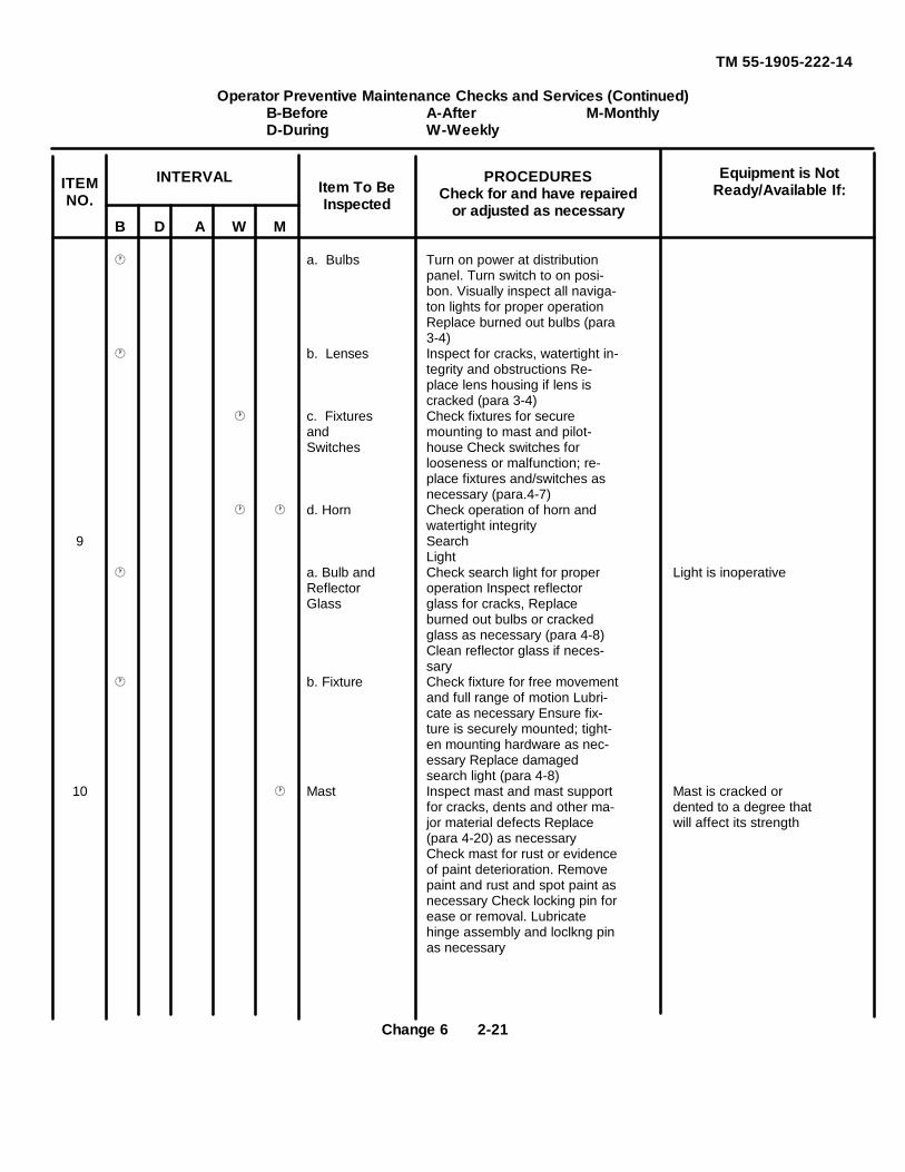
TM 55-1905-222-14
Operator Preventive Maintenance Checks and Services (Continued)B-Before A-After M-MonthlyD-During W-Weekly
B D A W M
a. Bulbs Turn on power at distributionpanel. Turn switch to on posi-bon. Visually inspect all naviga-ton lights for proper operationReplace burned out bulbs (para3-4)
b. Lenses Inspect for cracks, watertight in-tegrity and obstructions Re-place lens housing if lens iscracked (para 3-4)
c. Fixtures Check fixtures for secureand mounting to mast and pilot-Switches house Check switches for
looseness or malfunction; re-place fixtures and/switches asnecessary (para.4-7)
d. Horn Check operation of horn andwatertight integrity
9 SearchLight
a. Bulb and Check search light for proper Light is inoperativeReflector operation Inspect reflectorGlass glass for cracks, Replace
burned out bulbs or crackedglass as necessary (para 4-8)Clean reflector glass if neces-sary
b. Fixture Check fixture for free movementand full range of motion Lubri-cate as necessary Ensure fix-ture is securely mounted; tight-en mounting hardware as nec-essary Replace damagedsearch light (para 4-8)
10 Mast Inspect mast and mast support Mast is cracked orfor cracks, dents and other ma- dented to a degree thatjor material defects Replace will affect its strength(para 4-20) as necessaryCheck mast for rust or evidenceof paint deterioration. Removepaint and rust and spot paint asnecessary Check locking pin forease or removal. Lubricatehinge assembly and loclkng pinas necessary
Item To BeInspected
Equipment is NotReady/Available If:
INTERVALITEMNO.
PROCEDURESCheck for and have repaired
or adjusted as necessary
Change 6 2-21
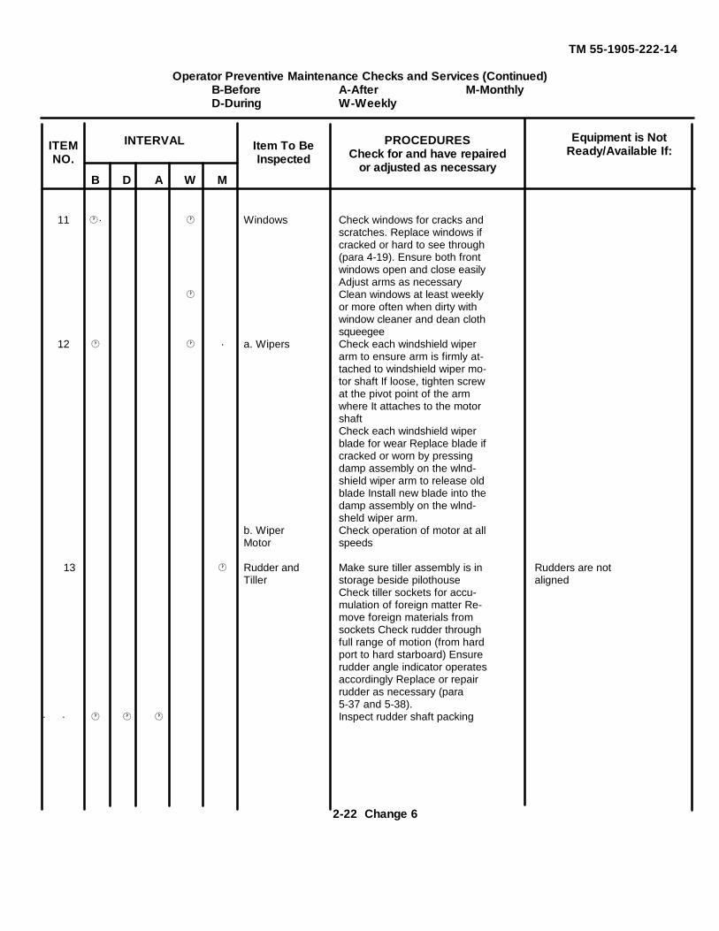
TM 55-1905-222-14
Operator Preventive Maintenance Checks and Services (Continued)B-Before A-After M-MonthlyD-During W-Weekly
B D A W M
11 · Windows Check windows for cracks andscratches. Replace windows ifcracked or hard to see through(para 4-19). Ensure both frontwindows open and close easilyAdjust arms as necessary
Clean windows at least weeklyor more often when dirty withwindow cleaner and dean clothsqueegee
12 · a. Wipers Check each windshield wiperarm to ensure arm is firmly at-tached to windshield wiper mo-tor shaft If loose, tighten screwat the pivot point of the armwhere It attaches to the motorshaftCheck each windshield wiperblade for wear Replace blade ifcracked or worn by pressingdamp assembly on the wlnd-shield wiper arm to release oldblade Install new blade into thedamp assembly on the wlnd-sheld wiper arm.
b. Wiper Check operation of motor at allMotor speeds
13 Rudder and Make sure tiller assembly is in Rudders are notTiller storage beside pilothouse aligned
Check tiller sockets for accu-mulation of foreign matter Re-move foreign materials fromsockets Check rudder throughfull range of motion (from hardport to hard starboard) Ensurerudder angle indicator operatesaccordingly Replace or repairrudder as necessary (para5-37 and 5-38).
· · Inspect rudder shaft packing
Item To BeInspected
Equipment is NotReady/Available If:
INTERVALITEMNO.
PROCEDURESCheck for and have repaired
or adjusted as necessary
2-22 Change 6
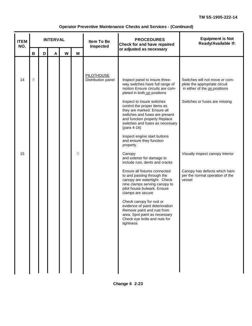
TM 5S-1905-222-14
Operator Preventive Maintenance Checks and Services - (Continued)
B D A W M
PILOTHOUSE14 Distribution panel Inspect panel to insure three- Switches will not move or com-
way switches have full range of plete the appropriate circuitmotion Ensure circuits are com- in either of the on positionspleted in both on positions
Inspect to insure switches Switches or fuses are missingcontrol the proper items asthey are marked. Ensure allswitches and fuses are presentand function properly Replaceswitches and fuses as necessary(para 4-16)
Inspect engine start buttonsand ensure they functionproperly.
15 Canopy Visually inspect canopy interiorand exterior for damage toinclude rust, dents and cracks
Ensure all fixtures connected Canopy has defects which ham-to and passing through the per the normal operation of thecanopy are watertight. Check vesselnine clamps serving canopy topilot house bulwark. Ensureclamps are secure
Check canopy for rust orevidence of paint deteriorationRemove paint and rust fromarea. Spot paint as necessaryCheck eye bolts and nuts fortightness
Item To BeInspected
Equipment is NotReady/Available If:
INTERVALITEMNO.
PROCEDURESCheck for and have repairedor adjusted as necessary
Change 6 2-23
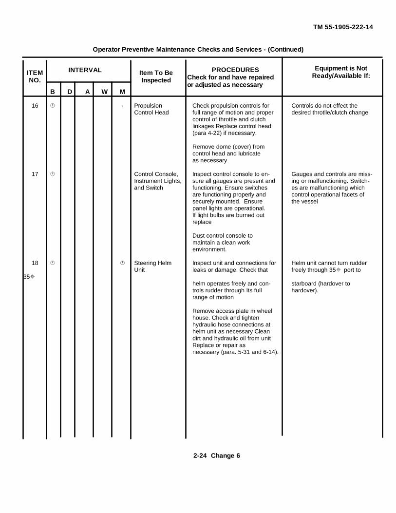
TM 55-1905-222-14
Operator Preventive Maintenance Checks and Services - (Continued)
B D A W M
16 · Propulsion Check propulsion controls for Controls do not effect theControl Head full range of motion and proper desired throtlle/clutch change
control of throttle and clutchlinkages Replace control head(para 4-22) if necessary.
Remove dome (cover) fromcontrol head and lubricateas necessary
17 Control Console, Inspect control console to en- Gauges and controls are miss-Instrument Lights, sure all gauges are present and ing or malfunctioning. Switch-and Switch functioning. Ensure switches es are malfunctioning which
are functioning properly and control operational facets ofsecurely mounted. Ensure the vesselpanel lights are operational.If light bulbs are burned outreplace
Dust control console tomaintain a clean workenvironment.
18 Steering Helm Inspect unit and connections for Helm unit cannot turn rudderUnit leaks or damage. Check that freely through 35 port to
35helm operates freely and con- starboard (hardover totrols rudder through Its full hardover).range of motion
Remove access plate m wheelhouse. Check and tightenhydraulic hose connections athelm unit as necessary Cleandirt and hydraulic oil from unitReplace or repair asnecessary (para. 5-31 and 6-14).
Item To BeInspected
Equipment is NotReady/Available If:
INTERVALITEMNO.
PROCEDURESCheck for and have repairedor adjusted as necessary
2-24 Change 6
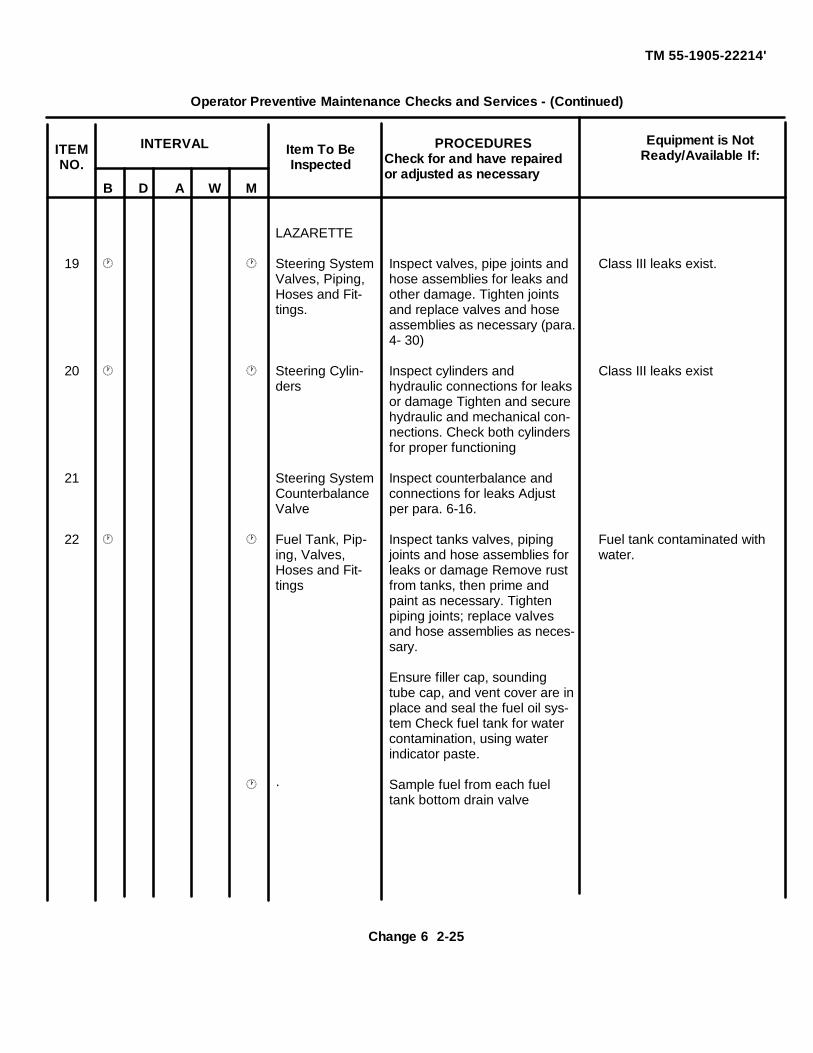
TM 55-1905-22214'
Operator Preventive Maintenance Checks and Services - (Continued)
B D A W M
LAZARETTE
19 Steering System Inspect valves, pipe joints and Class III leaks exist.Valves, Piping, hose assemblies for leaks andHoses and Fit- other damage. Tighten jointstings. and replace valves and hose
assemblies as necessary (para.4- 30)
20 Steering Cylin- Inspect cylinders and Class III leaks existders hydraulic connections for leaks
or damage Tighten and securehydraulic and mechanical con-nections. Check both cylindersfor proper functioning
21 Steering System Inspect counterbalance andCounterbalance connections for leaks AdjustValve per para. 6-16.
22 Fuel Tank, Pip- Inspect tanks valves, piping Fuel tank contaminated withing, Valves, joints and hose assemblies for water.Hoses and Fit- leaks or damage Remove rusttings from tanks, then prime and
paint as necessary. Tightenpiping joints; replace valvesand hose assemblies as neces-sary.
Ensure filler cap, soundingtube cap, and vent cover are inplace and seal the fuel oil sys-tem Check fuel tank for watercontamination, using waterindicator paste.
· Sample fuel from each fueltank bottom drain valve
Item To BeInspected
Equipment is NotReady/Available If:
INTERVALITEMNO.
PROCEDURESCheck for and have repairedor adjusted as necessary
Change 6 2-25
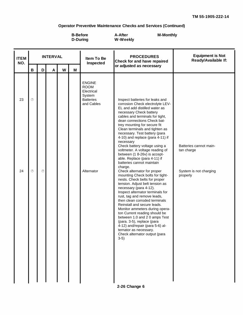
TM 55-1905-222-14
Operator Preventive Maintenance Checks and Services (Continued)
B-Before A-After M-MonthlyD-During W-Weekly
B D A W M
ENGINEROOMElectricalSystem
23 Batteries Inspect batteries for leaks andand Cables corrosion Check electrolyte LEV-
EL and add distilled water asnecessary Check batterycables and terminals for tight,dean connections Check bat-trey mounting for secure fitClean terminals and tighten asnecessary. Test battery (para4-10) and replace (para 4-11) ifnecessaryCheck battery voltage using a Batteries cannot main-voltmeter. A voltage reading of tan chargebetween (1 8-26v) is accept-able. Replace (para 4-11) ifbatteries cannot maintaincharge.
24 Alternator Check alternator for proper System is not chargingmounting Check bolts for tight- properlynests. Check belts for propertension. Adjust belt tension asnecessary (para 4-12).Inspect alternator terminals forrust, tag and remove leads,then clean corroded terminalsReinstall and secure leads.Monitor ammeters during opera-ton Current reading should bebetween 1.0 and 2 0 amps Test(para. 3-5), replace (para4-12) and/repair (para 5-6) al-ternator as necessary.Check alternator output (para3-5)
Item To BeInspected
Equipment is NotReady/Available If:
INTERVALITEMNO.
PROCEDURESCheck for and have repairedor adjusted as necessary
2-26 Change 6
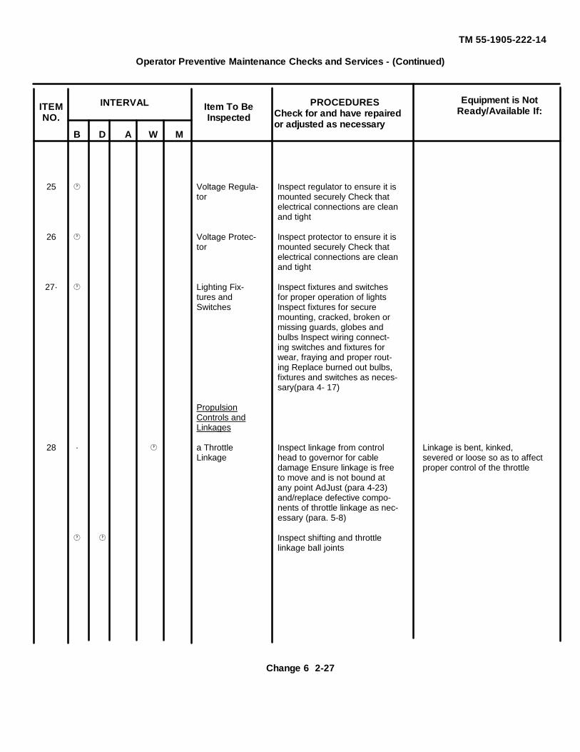
TM 55-1905-222-14
Operator Preventive Maintenance Checks and Services - (Continued)
B D A W M
25 Voltage Regula- Inspect regulator to ensure it istor mounted securely Check that
electrical connections are cleanand tight
26 Voltage Protec- Inspect protector to ensure it istor mounted securely Check that
electrical connections are cleanand tight
27· Lighting Fix- Inspect fixtures and switchestures and for proper operation of lightsSwitches Inspect fixtures for secure
mounting, cracked, broken ormissing guards, globes andbulbs Inspect wiring connect-ing switches and fixtures forwear, fraying and proper rout-ing Replace burned out bulbs,fixtures and switches as neces-sary(para 4- 17)
PropulsionControls andLinkages
28 · a Throttle Inspect linkage from control Linkage is bent, kinked,Linkage head to governor for cable severed or loose so as to affect
damage Ensure linkage is free proper control of the throttleto move and is not bound atany point AdJust (para 4-23)and/replace defective compo-nents of throttle linkage as nec-essary (para. 5-8)
Inspect shifting and throttlelinkage ball joints
Item To BeInspected
Equipment is NotReady/Available If:
INTERVALITEMNO.
PROCEDURESCheck for and have repairedor adjusted as necessary
Change 6 2-27
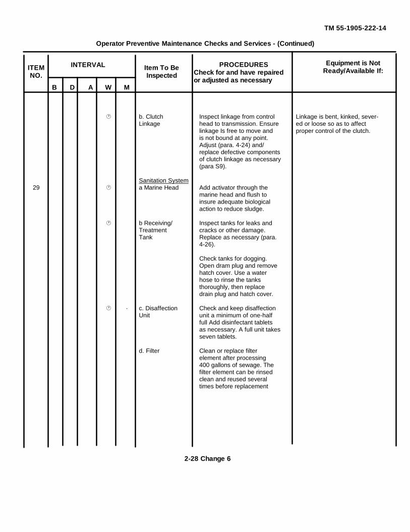
TM 55-1905-222-14
Operator Preventive Maintenance Checks and Services - (Continued)
B D A W M
b. Clutch Inspect linkage from control Linkage is bent, kinked, sever-Linkage head to transmission. Ensure ed or loose so as to affect
linkage Is free to move and proper control of the clutch.is not bound at any point.Adjust (para. 4-24) and/replace defective componentsof clutch linkage as necessary(para S9).
Sanitation System29 a Marine Head Add activator through the
marine head and flush toinsure adequate biologicalaction to reduce sludge.
b Receiving/ Inspect tanks for leaks andTreatment cracks or other damage.Tank Replace as necessary (para.
4-26).
Check tanks for dogging.Open dram plug and removehatch cover. Use a waterhose to rinse the tanksthoroughly, then replacedrain plug and hatch cover.
· c. Disaffection Check and keep disaffectionUnit unit a minimum of one-half
full Add disinfectant tabletsas necessary. A full unit takesseven tablets.
d. Filter Clean or replace filterelement after processing400 gallons of sewage. Thefilter element can be rinsedclean and reused severaltimes before replacement
Item To BeInspected
Equipment is NotReady/Available If:
INTERVALITEMNO.
PROCEDURESCheck for and have repairedor adjusted as necessary
2-28 Change 6
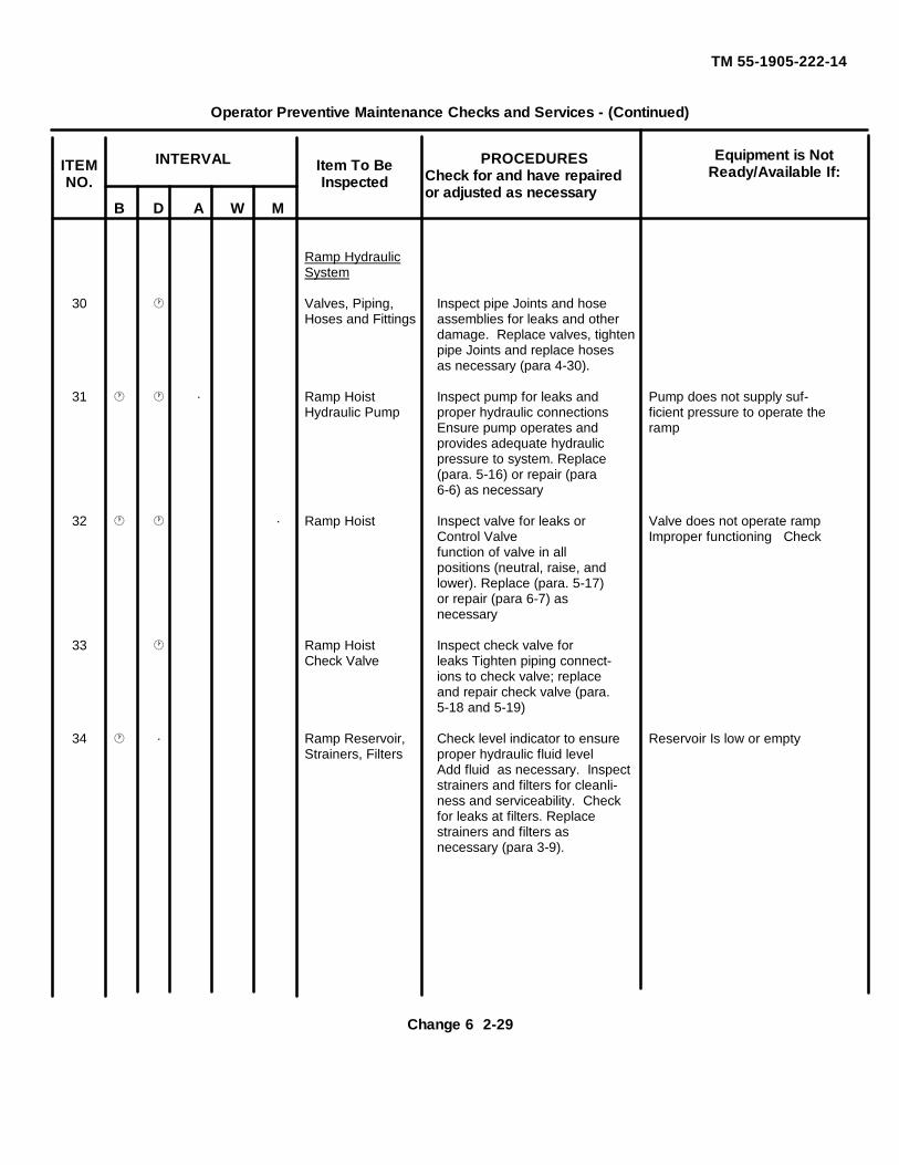
TM 55-1905-222-14
Operator Preventive Maintenance Checks and Services - (Continued)
B D A W M
Ramp HydraulicSystem
30 Valves, Piping, Inspect pipe Joints and hoseHoses and Fittings assemblies for leaks and other
damage. Replace valves, tightenpipe Joints and replace hosesas necessary (para 4-30).
31 · Ramp Hoist Inspect pump for leaks and Pump does not supply suf-Hydraulic Pump proper hydraulic connections ficient pressure to operate the
Ensure pump operates and rampprovides adequate hydraulicpressure to system. Replace(para. 5-16) or repair (para6-6) as necessary
32 · Ramp Hoist Inspect valve for leaks or Valve does not operate rampControl Valve Improper functioning Checkfunction of valve in allpositions (neutral, raise, andlower). Replace (para. 5-17)or repair (para 6-7) asnecessary
33 Ramp Hoist Inspect check valve forCheck Valve leaks Tighten piping connect-
ions to check valve; replaceand repair check valve (para.5-18 and 5-19)
34 · Ramp Reservoir, Check level indicator to ensure Reservoir Is low or emptyStrainers, Filters proper hydraulic fluid level
Add fluid as necessary. Inspectstrainers and filters for cleanli-ness and serviceability. Checkfor leaks at filters. Replacestrainers and filters asnecessary (para 3-9).
Item To BeInspected
Equipment is NotReady/Available If:
INTERVALITEMNO.
PROCEDURESCheck for and have repairedor adjusted as necessary
Change 6 2-29

TM 55-1905-222-14
Operator Preventive Maintenance Checks and Services - (Continued)
B D A W M
Steering System
35 · a Valves, Piping Inspect valves, pipe joints and Class III leaks existHoses and Fit- hose assemblies for leaks andting other damage. Tighten joints
and replace valves and hoseassemblies as necessary (para4-30).
b. Steering Pump Inspect pump and connecting Both pumps do not functionhose assemblies for leaks.Ensure pump is properlymounted, tighten pumpconnections as necessary. Ifpumps cannot supply thenecessary system pressure,investigate and replace orrepair (para. 5-29 and 6-12)as necessary.
c. Relief Valve Inspect valve and connectionsfor leaks. Tighten connectionsas necessary. Replace or repairas necessary (para. 5-32 and5-33).
d. Flow Divider Inspect divider and connectionsfor leaks. Tighten connectionsas necessary. Replace or repairas necessary (para. 5-34 and6-15).
e. Check Valve Inspect valve and connectionsfor leaks. Tighten connectionsas necessary. Replace or repairas necessary (para 4-33 and5-36).
Item To BeInspected
Equipment is NotReady/Available If:
INTERVALITEMNO.
PROCEDURESCheck for and have repairedor adjusted as necessary
2-30 Change 6
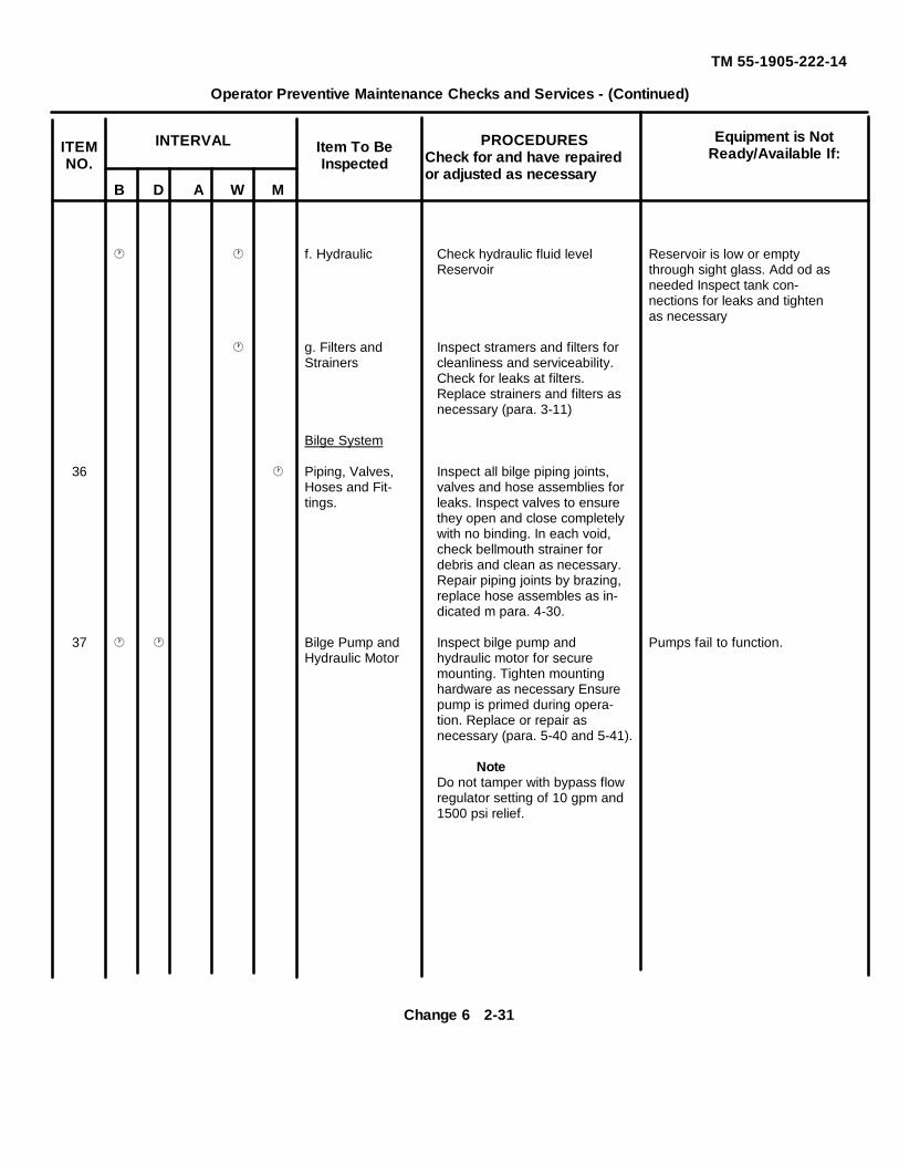
TM 55-1905-222-14
Operator Preventive Maintenance Checks and Services - (Continued)
B D A W M
f. Hydraulic Check hydraulic fluid level Reservoir is low or emptyReservoir through sight glass. Add od as
needed Inspect tank con-nections for leaks and tightenas necessary
g. Filters and Inspect stramers and filters forStrainers cleanliness and serviceability.
Check for leaks at filters.Replace strainers and filters asnecessary (para. 3-11)
Bilge System
36 Piping, Valves, Inspect all bilge piping joints,Hoses and Fit- valves and hose assemblies fortings. leaks. Inspect valves to ensure
they open and close completelywith no binding. In each void,check bellmouth strainer fordebris and clean as necessary.Repair piping joints by brazing,replace hose assembles as in-dicated m para. 4-30.
37 Bilge Pump and Inspect bilge pump and Pumps fail to function.Hydraulic Motor hydraulic motor for secure
mounting. Tighten mountinghardware as necessary Ensurepump is primed during opera-tion. Replace or repair asnecessary (para. 5-40 and 5-41).
NoteDo not tamper with bypass flowregulator setting of 10 gpm and1500 psi relief.
Item To BeInspected
Equipment is NotReady/Available If:
INTERVALITEMNO.
PROCEDURESCheck for and have repairedor adjusted as necessary
Change 6 2-31
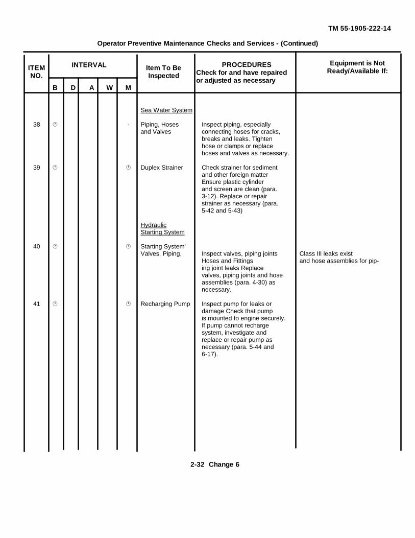
TM 55-1905-222-14
Operator Preventive Maintenance Checks and Services - (Continued)
B D A W M
Sea Water System
38 · Piping, Hoses Inspect piping, especiallyand Valves connecting hoses for cracks,
breaks and leaks. Tightenhose or clamps or replacehoses and valves as necessary.
39 Duplex Strainer Check strainer for sedimentand other foreign matterEnsure plastic cylinderand screen are clean (para.3-12). Replace or repairstrainer as necessary (para.5-42 and 5-43)
HydraulicStarting System
40 Starting System'Valves, Piping, Inspect valves, piping joints Class III leaks exist
Hoses and Fittings and hose assemblies for pip-ing joint leaks Replacevalves, piping joints and hoseassemblies (para. 4-30) asnecessary.
41 Recharging Pump Inspect pump for leaks ordamage Check that pumpis mounted to engine securely.If pump cannot rechargesystem, investigate andreplace or repair pump asnecessary (para. 5-44 and6-17).
Item To BeInspected
Equipment is NotReady/Available If:
INTERVALITEMNO.
PROCEDURESCheck for and have repairedor adjusted as necessary
2-32 Change 6
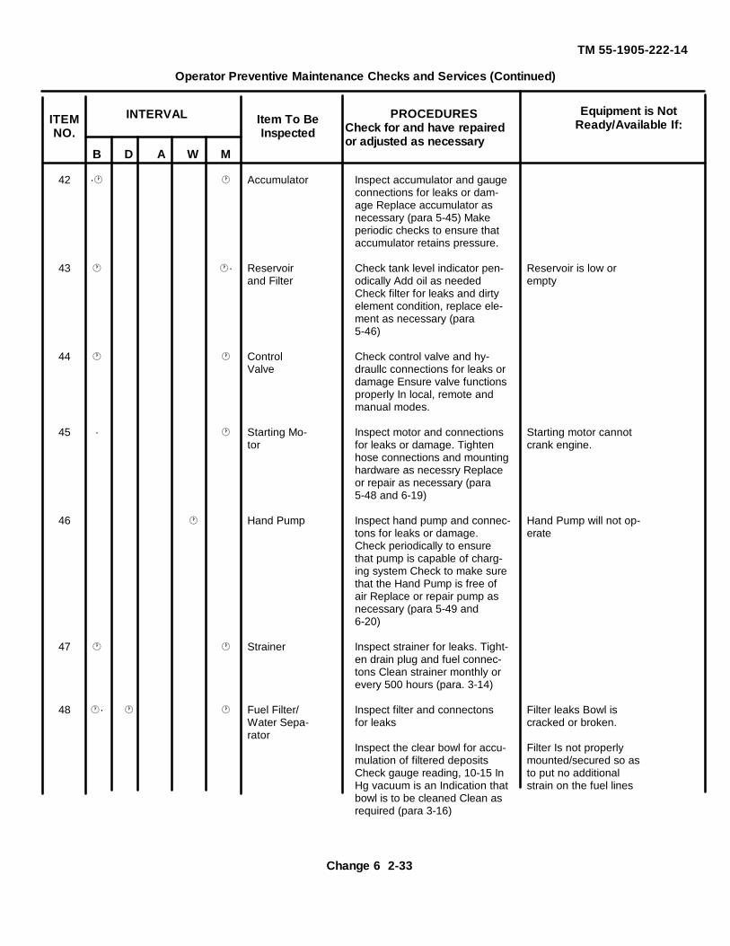
TM 55-1905-222-14
Operator Preventive Maintenance Checks and Services (Continued)
B D A W M
42 · Accumulator Inspect accumulator and gaugeconnections for leaks or dam-age Replace accumulator asnecessary (para 5-45) Makeperiodic checks to ensure thataccumulator retains pressure.
43 · Reservoir Check tank level indicator pen- Reservoir is low orand Filter odically Add oil as needed empty
Check filter for leaks and dirtyelement condition, replace ele-ment as necessary (para5-46)
44 Control Check control valve and hy-Valve draullc connections for leaks or
damage Ensure valve functionsproperly In local, remote andmanual modes.
45 · Starting Mo- Inspect motor and connections Starting motor cannottor for leaks or damage. Tighten crank engine.
hose connections and mountinghardware as necessry Replaceor repair as necessary (para5-48 and 6-19)
46 Hand Pump Inspect hand pump and connec- Hand Pump will not op-tons for leaks or damage. erateCheck periodically to ensurethat pump is capable of charg-ing system Check to make surethat the Hand Pump is free ofair Replace or repair pump asnecessary (para 5-49 and6-20)
47 Strainer Inspect strainer for leaks. Tight-en drain plug and fuel connec-tons Clean strainer monthly orevery 500 hours (para. 3-14)
48 · Fuel Filter/ Inspect filter and connectons Filter leaks Bowl isWater Sepa- for leaks cracked or broken.rator
Inspect the clear bowl for accu- Filter Is not properlymulation of filtered deposits mounted/secured so asCheck gauge reading, 10-15 In to put no additionalHg vacuum is an Indication that strain on the fuel linesbowl is to be cleaned Clean asrequired (para 3-16)
Item To BeInspected
Equipment is NotReady/Available If:
INTERVALITEMNO.
PROCEDURESCheck for and have repairedor adjusted as necessary
Change 6 2-33
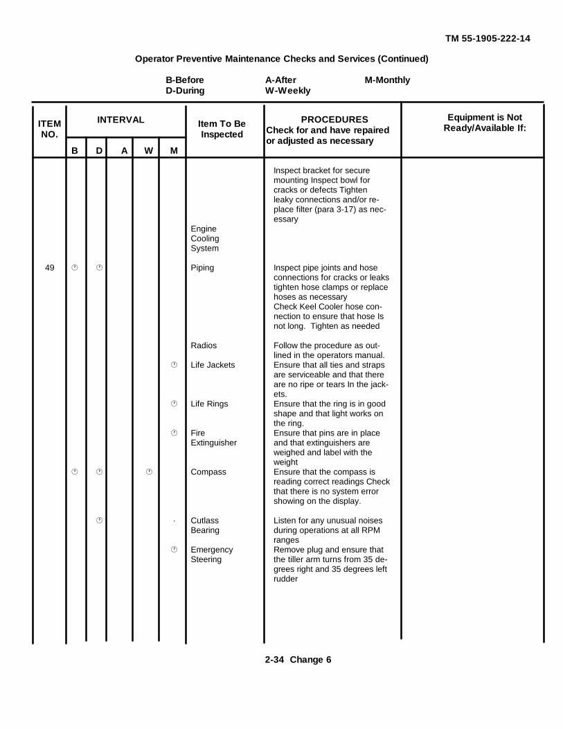
TM 55-1905-222-14
Operator Preventive Maintenance Checks and Services (Continued)
B-Before A-After M-MonthlyD-During W-Weekly
B D A W M
Inspect bracket for securemounting Inspect bowl forcracks or defects Tightenleaky connections and/or re-place filter (para 3-17) as nec-essary
EngineCoolingSystem
49 Piping Inspect pipe joints and hoseconnections for cracks or leakstighten hose clamps or replacehoses as necessaryCheck Keel Cooler hose con-nection to ensure that hose Isnot long. Tighten as needed
Radios Follow the procedure as out-lined in the operators manual.
Life Jackets Ensure that all ties and strapsare serviceable and that thereare no ripe or tears In the jack-ets.
Life Rings Ensure that the ring is in goodshape and that light works onthe ring.
Fire Ensure that pins are in placeExtinguisher and that extinguishers are
weighed and label with theweight
Compass Ensure that the compass isreading correct readings Checkthat there is no system errorshowing on the display.
· Cutlass Listen for any unusual noisesBearing during operations at all RPM
ranges Emergency Remove plug and ensure that
Steering the tiller arm turns from 35 de-grees right and 35 degrees leftrudder
Item To BeInspected
Equipment is NotReady/Available If:
INTERVALITEMNO.
PROCEDURESCheck for and have repairedor adjusted as necessary
2-34 Change 6
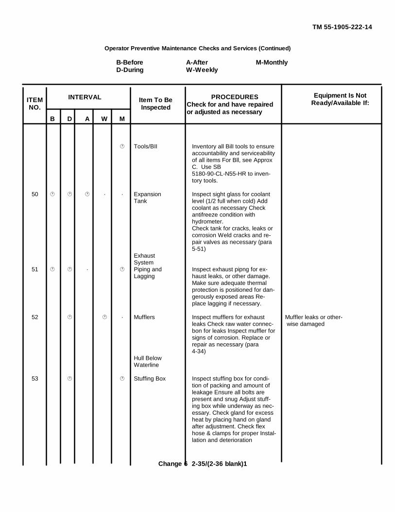
TM 55-1905-222-14
Operator Preventive Maintenance Checks and Services (Continued)
B-Before A-After M-MonthlyD-During W-Weekly
B D A W M
Tools/BII Inventory all BilI tools to ensureaccountability and serviceabilityof all items For Bll, see ApproxC. Use SB5180-90-CL-N55-HR to inven-tory tools.
50 · · Expansion Inspect sight glass for coolantTank level (1/2 full when cold) Add
coolant as necessary Checkantifreeze condition withhydrometer.Check tank for cracks, leaks orcorrosion Weld cracks and re-pair valves as necessary (para5-51)
ExhaustSystem
51 · Piping and Inspect exhaust pipng for ex-Lagging haust leaks, or other damage.
Make sure adequate thermalprotection is positioned for dan-gerously exposed areas Re-place lagging if necessary.
52 · Mufflers Inspect mufflers for exhaust Muffler leaks or other-leaks Check raw water connec- wise damagedbon for leaks Inspect muffler forsigns of corrosion. Replace orrepair as necessary (para4-34)
Hull BelowWaterline
53 Stuffing Box Inspect stuffing box for condi-tion of packing and amount ofleakage Ensure all bolts arepresent and snug Adjust stuff-ing box while underway as nec-essary. Check gland for excessheat by placing hand on glandafter adjustment. Check flexhose & clamps for proper Instal-lation and deterioration
Item To BeInspected
Equipment Is NotReady/Available If:
INTERVALITEMNO.
PROCEDURESCheck for and have repairedor adjusted as necessary
Change 6 2-35/(2-36 blank)1
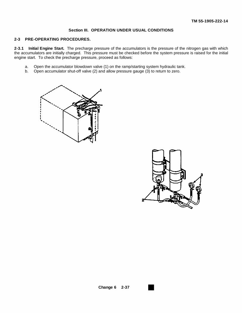
TM 55-1905-222-14
Section III. OPERATION UNDER USUAL CONDITIONS
2-3 PRE-OPERATING PROCEDURES.
2-3.1 Initial Engine Start. The precharge pressure of the accumulators is the pressure of the nitrogen gas with whichthe accumulators are initially charged. This pressure must be checked before the system pressure is raised for the initialengine start. To check the precharge pressure, proceed as follows:
a. Open the accumulator blowdown valve (1) on the ramp/starting system hydraulic tank.b. Open accumulator shut-off valve (2) and allow pressure gauge (3) to return to zero.
Change 6 2-37
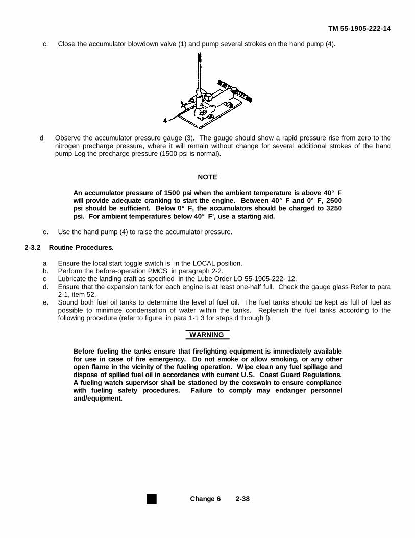
TM 55-1905-222-14
c. Close the accumulator blowdown valve (1) and pump several strokes on the hand pump (4).
d Observe the accumulator pressure gauge (3). The gauge should show a rapid pressure rise from zero to thenitrogen precharge pressure, where it will remain without change for several additional strokes of the handpump Log the precharge pressure (1500 psi is normal).
NOTE
An accumulator pressure of 1500 psi when the ambient temperature is above 40°Fwill provide adequate cranking to start the engine. Between 40°F and 0°F, 2500psi should be sufficient. Below 0°F, the accumulators should be charged to 3250psi. For ambient temperatures below 40°F', use a starting aid.
e. Use the hand pump (4) to raise the accumulator pressure.
2-3.2 Routine Procedures.
a Ensure the local start toggle switch is in the LOCAL position.b. Perform the before-operation PMCS in paragraph 2-2.c Lubricate the landing craft as specified in the Lube Order LO 55-1905-222- 12.d. Ensure that the expansion tank for each engine is at least one-half full. Check the gauge glass Refer to para
2-1, item 52.e. Sound both fuel oil tanks to determine the level of fuel oil. The fuel tanks should be kept as full of fuel as
possible to minimize condensation of water within the tanks. Replenish the fuel tanks according to thefollowing procedure (refer to figure in para 1-1 3 for steps d through f):
WARNING
Before fueling the tanks ensure that firefighting equipment is immediately availablefor use in case of fire emergency. Do not smoke or allow smoking, or any otheropen flame in the vicinity of the fueling operation. Wipe clean any fuel spillage anddispose of spilled fuel oil in accordance with current U.S. Coast Guard Regulations.A fueling watch supervisor shall be stationed by the coxswain to ensure compliancewith fueling safety procedures. Failure to comply may endanger personneland/equipment.
Change 6 2-38
TM 55-1905-222-14
(1) Close the fuel oil return valves to ensure that the tanks will be fully replenished.(2) Remove the cap on the fuel fill connection behind the pilothouse.(3) Open the filling valve in the fuel fill piping to tank to be filled. (The valve is located in the lazarette ).(4) Fill the fuel tank to about 95 percent capacity with clean diesel fuel.(5) Close the fuel filling valve in the lazarette.(6) Open the fuel oil return valves in the engine room.(7) Secure the cap on the fuel fill connection and the deck plate for sounding the tanks (if not already
closed).(8) Repeat steps 1 through 8 for the other tank.
f. Open both fuel oil suction valves in the lazarette.g. Open both fuel oil supply valves and return valves in the engine room.h. Open both sea water suction valves and discharge valves in the engine room. Ensure that sea water is
discharging at the overboard and exhaust outlets. Refer to figure in para. 1- 16.i. Ensure that both PTO clutch levers are disengaged. Refer to figure in para 2-1, item 58.j. Open one accumulator shut-off valve for each engine. Refer to figure in para 1-17. Ensure that the other
accumulator valves are closed for reserve stand-by.k. Open steering reservoir suction valves. Refer to figure in para. 1- 18.I. Open the suction line shut-off valve below the starting system hydraulic tank. Refer to figure in para 1-17.m. Ensure that pins on the throttle control unit and clutch control unit are engaged for remote control. Refer to
figures in para. 2-1, items 56 and 57.n. Ensure that the local start toggle switches mounted on the inboard side of the engine room instrument panels
are in REMOTE position. Refer to figure m para 2-1, item 46.
Change 6 2-39
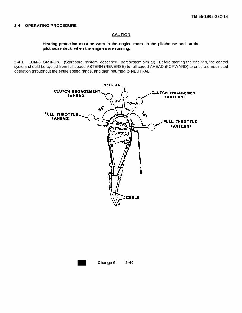
TM 55-1905-222-14
2-4 OPERATING PROCEDURE
CAUTION
Hearing protection must be worn in the engine room, in the pilothouse and on thepilothouse deck when the engines are running.
2-4.1 LCM-8 Start-Up. (Starboard system described, port system similar). Before starting the engines, the controlsystem should be cycled from full speed ASTERN (REVERSE) to full speed AHEAD (FORWARD) to ensure unrestrictedoperation throughout the entire speed range, and then returned to NEUTRAL.
Change 6 2-40
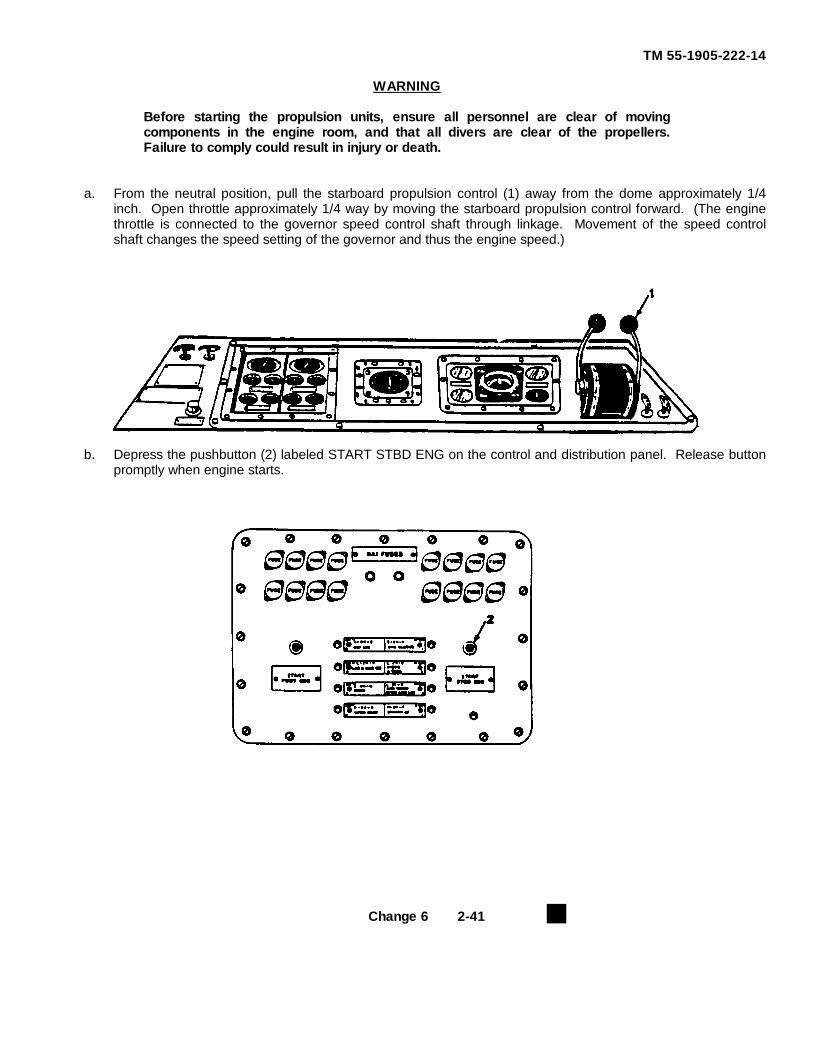
TM 55-1905-222-14
WARNING
Before starting the propulsion units, ensure all personnel are clear of movingcomponents in the engine room, and that all divers are clear of the propellers.Failure to comply could result in injury or death.
a. From the neutral position, pull the starboard propulsion control (1) away from the dome approximately 1/4inch. Open throttle approximately 1/4 way by moving the starboard propulsion control forward. (The enginethrottle is connected to the governor speed control shaft through linkage. Movement of the speed controlshaft changes the speed setting of the governor and thus the engine speed.)
b. Depress the pushbutton (2) labeled START STBD ENG on the control and distribution panel. Release buttonpromptly when engine starts.
Change 6 2-41
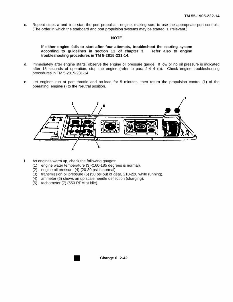
TM 55-1905-222-14
c. Repeat steps a and b to start the port propulsion engine, making sure to use the appropriate port controls.(The order in which the starboard and port propulsion systems may be started is irrelevant.)
NOTE
If either engine fails to start after four attempts, troubleshoot the starting systemaccording to guidelines in section 11 of chapter 3. Refer also to enginetroubleshooting procedures in TM 5-2815-231-14.
d. Immediately after engine starts, observe the engine oil pressure gauge. If low or no oil pressure is indicatedafter 15 seconds of operation, stop the engine (refer to para 2-4 4 (f)). Check engine troubleshootingprocedures in TM 5-2815-231-14.
e. Let engines run at part throttle and no-load for 5 minutes, then return the propulsion control (1) of theoperating engine(s) to the Neutral position.
f. As engines warm up, check the following gauges:(1) engine water temperature (3)-(160-185 degrees is normal).(2) engine oil pressure (4)-(20-30 psi is normal).(3) transmission oil pressure (5) (50 psi out of gear, 210-220 while running).(4) ammeter (6) shows an up scale needle deflection (charging).(5) tachometer (7) (550 RPM at idle).
Change 6 2-42
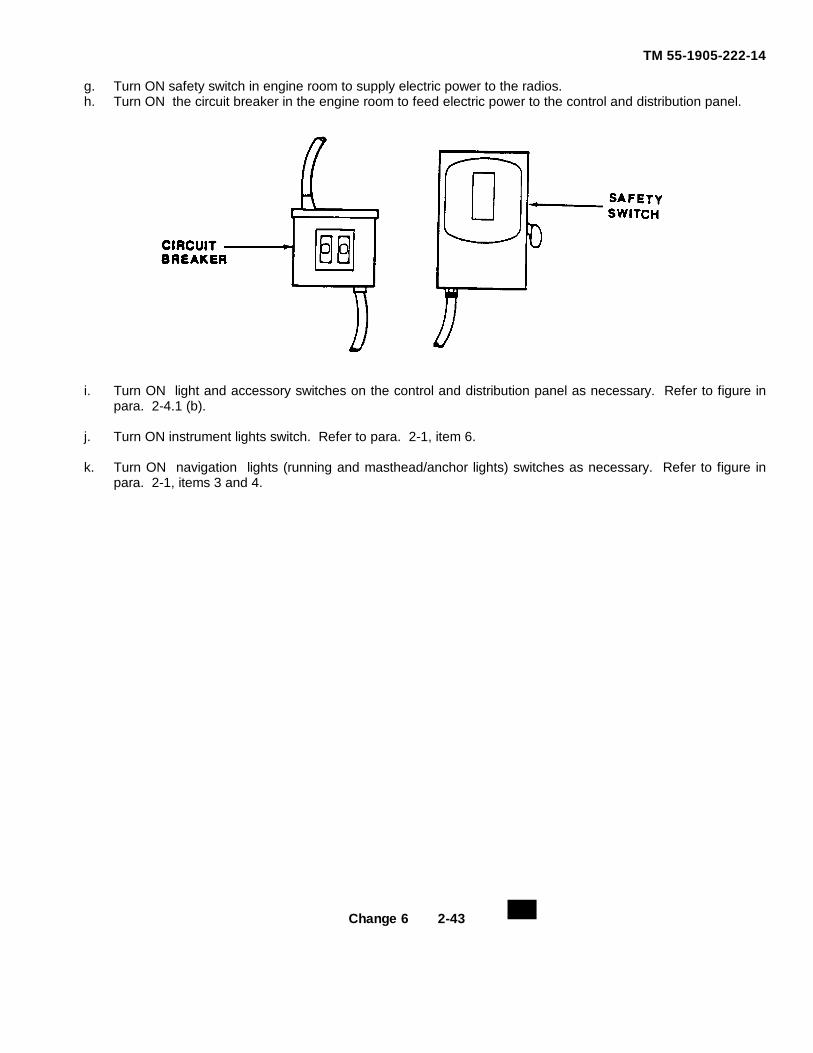
TM 55-1905-222-14
g. Turn ON safety switch in engine room to supply electric power to the radios.h. Turn ON the circuit breaker in the engine room to feed electric power to the control and distribution panel.
i. Turn ON light and accessory switches on the control and distribution panel as necessary. Refer to figure inpara. 2-4.1 (b).
j. Turn ON instrument lights switch. Refer to para. 2-1, item 6.
k. Turn ON navigation lights (running and masthead/anchor lights) switches as necessary. Refer to figure inpara. 2-1, items 3 and 4.
Change 6 2-43
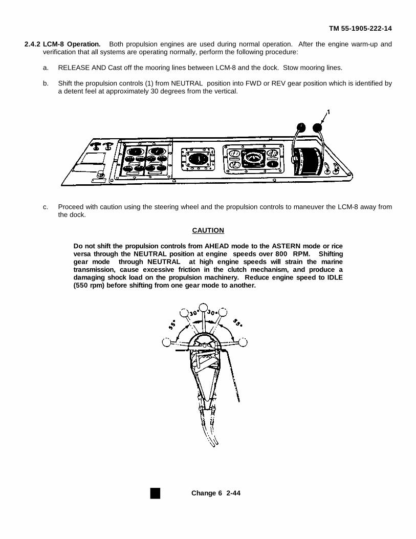
TM 55-1905-222-14
2.4.2 LCM-8 Operation. Both propulsion engines are used during normal operation. After the engine warm-up andverification that all systems are operating normally, perform the following procedure:
a. RELEASE AND Cast off the mooring lines between LCM-8 and the dock. Stow mooring lines.
b. Shift the propulsion controls (1) from NEUTRAL position into FWD or REV gear position which is identified bya detent feel at approximately 30 degrees from the vertical.
c. Proceed with caution using the steering wheel and the propulsion controls to maneuver the LCM-8 away fromthe dock.
CAUTION
Do not shift the propulsion controls from AHEAD mode to the ASTERN mode or riceversa through the NEUTRAL position at engine speeds over 800 RPM. Shiftinggear mode through NEUTRAL at high engine speeds will strain the marinetransmission, cause excessive friction in the clutch mechanism, and produce adamaging shock load on the propulsion machinery. Reduce engine speed to IDLE(550 rpm) before shifting from one gear mode to another.
Change 6 2-44
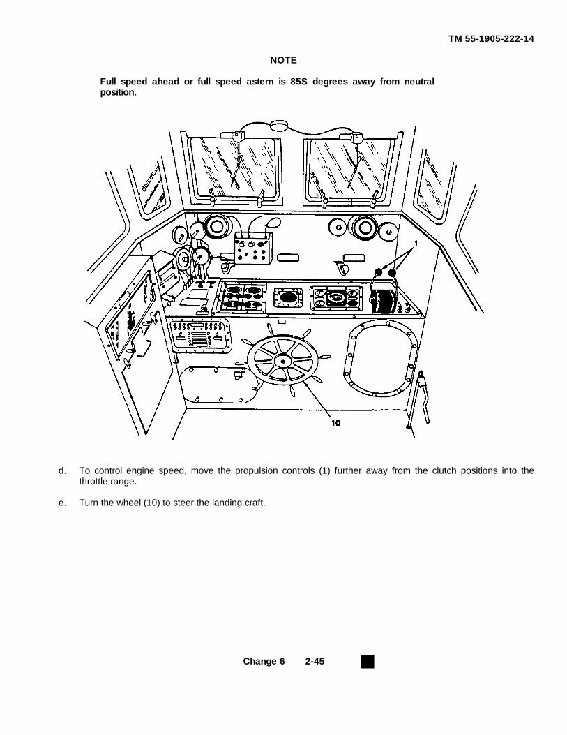
TM 55-1905-222-14
NOTE
Full speed ahead or full speed astern is 85S degrees away from neutralposition.
d. To control engine speed, move the propulsion controls (1) further away from the clutch positions into thethrottle range.
e. Turn the wheel (10) to steer the landing craft.
Change 6 2-45
TM 55-1905-222-14
2-4.2.1 Mooring Procedure. Ensure the LCM-8 mooring lines are in proper repair and secured to the mooring bittsat the appropriate deck stations before approaching a moorage. Perform the following mooring procedure:
WARNING
Secure mooring lines only to mooring bitts. Never secure mooring lines to handrailsor other deck hardware not intended for mooring purposes. Failure to comply mayresult in damage to the vessel and injury or death to personnel.
a. Cautiously maneuver the LCM-8 to the desired location alongside the pier or dock.b. Cast the LCM-8 mooring lines to assisting personnel on the pier or dock.c. Take up slack and secure the mooring lines to mooring cleats or bitts on the pier or dock.
NOTE
Under normal conditions, one mooring line forward and one mooring line aft aresufficient to moor the LCM-8. In high wind or strong current conditions, additionallines will be required to moor the vessel.
2-4.2.2 Anchoring. Observe the following guidelines when anchoring the LCM-8.
a. Assemble the LCM-8 ground tackle by connecting the anchor to the anchor chain and line.b. Head the boat into the wind or seas at the location where the anchor is to be dropped.c. Run the vessel slow ahead until it is keeping station into the wind or seas.
WARNING
An anchoring supervisor shall be stationed to ensure that personnel do not becomeentangled in the anchor line while it is paying out. Failure to comply may result ininjury or death to personnel.
d. Lower the anchor from the bow to the water and pay out anchor line until the anchor reaches the bottom.e. Allow the vessel to drift astern with the wind or seas until a scope of line about six times the depth of water is
paid out.f. Lay the anchor line in a bow chock and secure it to a mooring bit. When the line becomes taut, set the anchor
by BACKING the vessel with the engines at IDLE speed.g. When a strain on the anchor line is achieved, indicating the anchor is set, return the propulsion control levers
to NEUTRAL position. LCM-8 is anchored.
Change 6 2-46
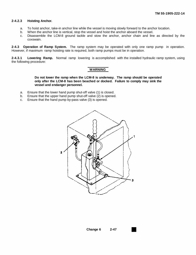
TM 55-1905-222-14
2-4.2.3 Hoisting Anchor.
a. To hoist anchor, take-in anchor line while the vessel is moving slowly forward to the anchor location.b. When the anchor line is vertical, stop the vessel and hoist the anchor aboard the vessel.c. Disassemble the LCM-8 ground tackle and stow the anchor, anchor chain and line as directed by the
coxswain.
2-4.3 Operation of Ramp System. The ramp system may be operated with only one ramp pump in operation.However, if maximum ramp hoisting rate is required, both ramp pumps must be in operation.
2-4.3.1 Lowering Ramp. Normal ramp lowering is accomplished with the installed hydraulic ramp system, usingthe following procedure:
WARNING
Do not lower the ramp when the LCM-8 is underway. The ramp should be operatedonly after the LCM-8 has been beached or docked. Failure to comply may sink thevessel and endanger personnel.
a. Ensure that the lower hand pump shut-off valve (1) is closed.b. Ensure that the upper hand pump shut-off valve (2) is opened.c. Ensure that the hand pump by-pass valve (3) is opened.
Change 6 2-47
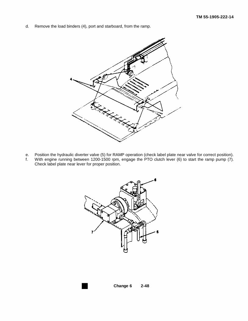
TM 55-1905-222-14
d. Remove the load binders (4), port and starboard, from the ramp.
e. Position the hydraulic diverter valve (5) for RAMP operation (check label plate near valve for correct position).f. With engine running between 1200-1500 rpm, engage the PTO clutch lever (6) to start the ramp pump (7).
Check label plate near lever for proper position.
Change 6 2-48
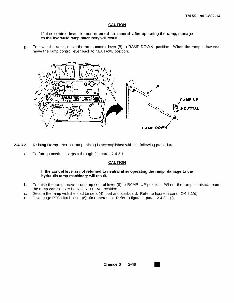
TM 55-1905-222-14
CAUTION
If the control lever is not returned to neutral after operating the ramp, damageto the hydraulic ramp machinery will result.
g. To lower the ramp, move the ramp control lever (8) to RAMP DOWN position. When the ramp is lowered,move the ramp control lever back to NEUTRAL position.
2-4.3.2 Raising Ramp. Normal ramp raising is accomplished with the following procedure:
a. Perform procedural steps a through f in para. 2-4.3.1.
CAUTION
If the control lever is not returned to neutral after operating the ramp, damage to thehydraulic ramp machinery will result.
b. To raise the ramp, move the ramp control lever (8) to RAMP UP position. When the ramp is raised, returnthe ramp control lever back to NEUTRAL position.
c. Secure the ramp with the load binders (4), port and starboard. Refer to figure in para. 2-4 3.1(d).d. Disengage PTO clutch lever (6) after operation. Refer to figure in para. 2-4.3.1 (f).
Change 6 2-49
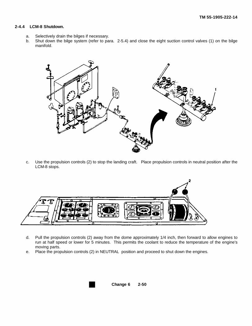
TM 55-1905-222-14
2-4.4 LCM-8 Shutdown.
a. Selectively drain the bilges if necessary.b. Shut down the bilge system (refer to para. 2-5.4) and close the eight suction control valves (1) on the bilge
manifold.
c. Use the propulsion controls (2) to stop the landing craft. Place propulsion controls in neutral position after theLCM-8 stops.
d. Pull the propulsion controls (2) away from the dome approximately 1/4 inch, then forward to allow engines torun at half speed or lower for 5 minutes. This permits the coolant to reduce the temperature of the engine'smoving parts.
e. Place the propulsion controls (2) in NEUTRAL position and proceed to shut down the engines.
Change 6 2-50
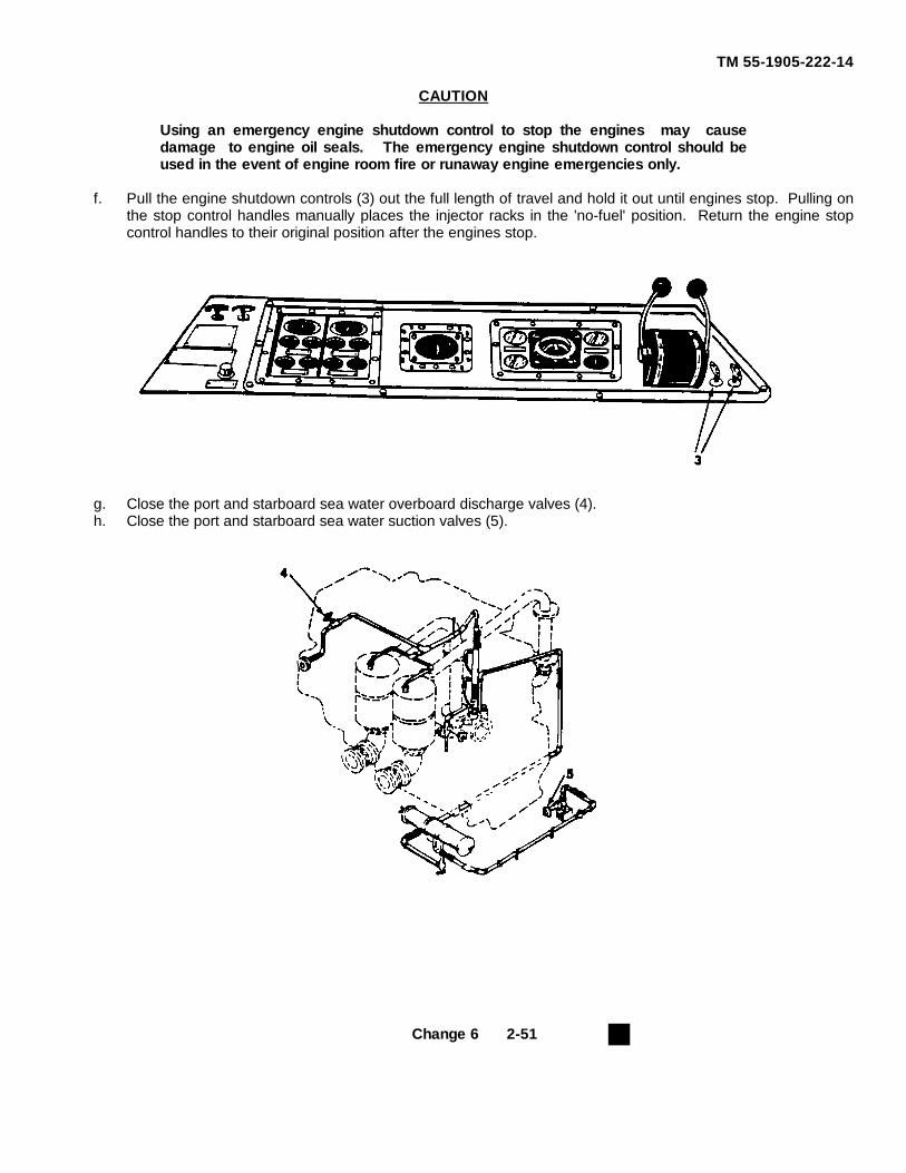
TM 55-1905-222-14
CAUTION
Using an emergency engine shutdown control to stop the engines may causedamage to engine oil seals. The emergency engine shutdown control should beused in the event of engine room fire or runaway engine emergencies only.
f. Pull the engine shutdown controls (3) out the full length of travel and hold it out until engines stop. Pulling onthe stop control handles manually places the injector racks in the 'no-fuel' position. Return the engine stopcontrol handles to their original position after the engines stop.
g. Close the port and starboard sea water overboard discharge valves (4).h. Close the port and starboard sea water suction valves (5).
Change 6 2-51
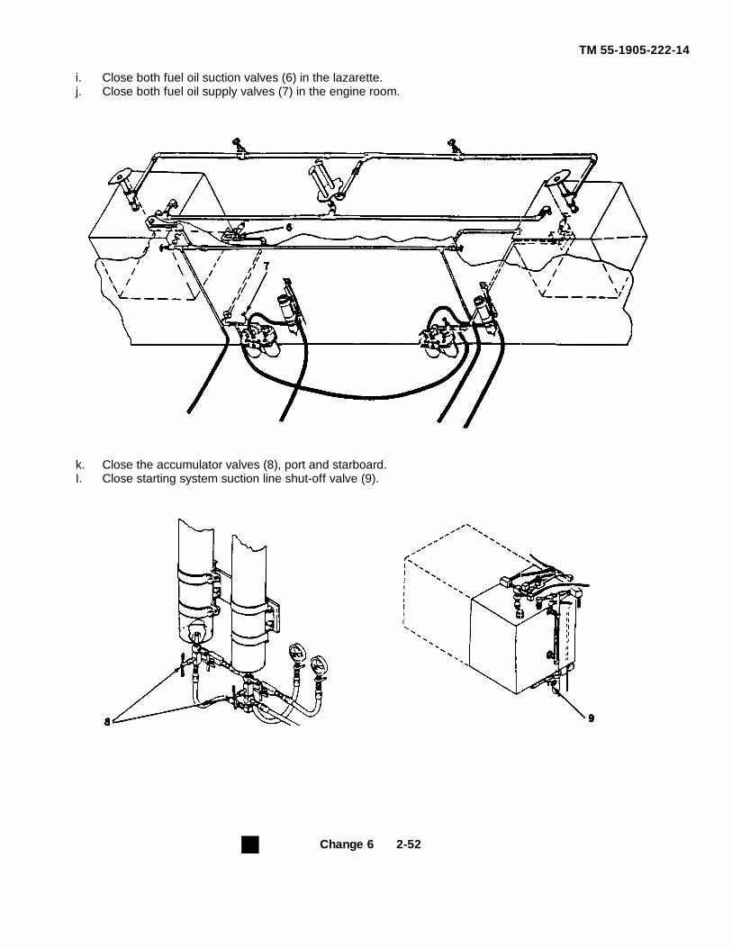
TM 55-1905-222-14
i. Close both fuel oil suction valves (6) in the lazarette.j. Close both fuel oil supply valves (7) in the engine room.
k. Close the accumulator valves (8), port and starboard.I. Close starting system suction line shut-off valve (9).
Change 6 2-52
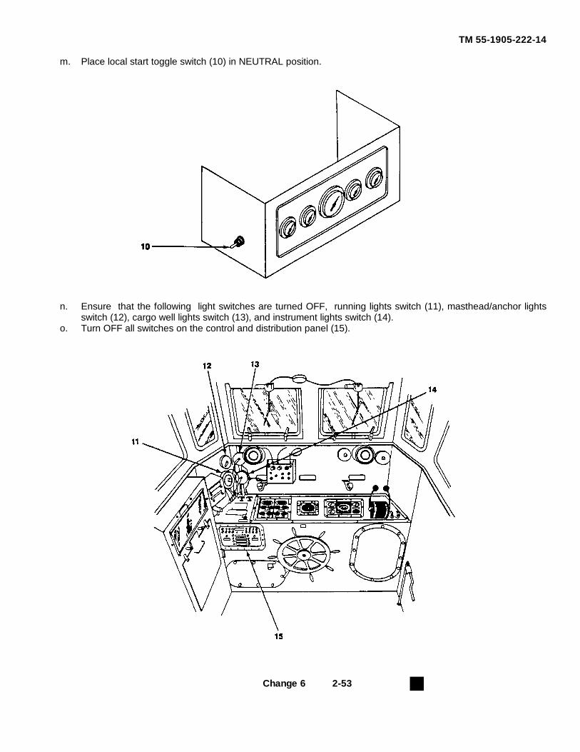
TM 55-1905-222-14
m. Place local start toggle switch (10) in NEUTRAL position.
n. Ensure that the following light switches are turned OFF, running lights switch (11), masthead/anchor lightsswitch (12), cargo well lights switch (13), and instrument lights switch (14).
o. Turn OFF all switches on the control and distribution panel (15).
Change 6 2-53
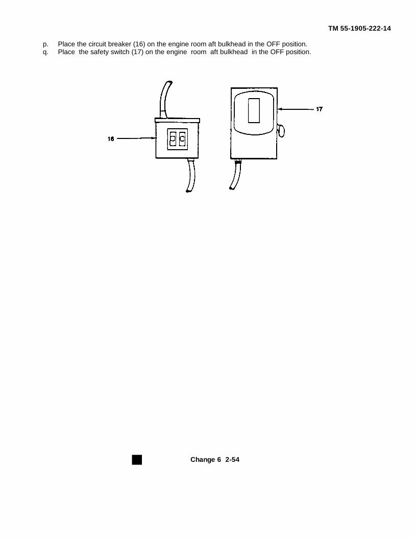
TM 55-1905-222-14
p. Place the circuit breaker (16) on the engine room aft bulkhead in the OFF position.q. Place the safety switch (17) on the engine room aft bulkhead in the OFF position.
Change 6 2-54
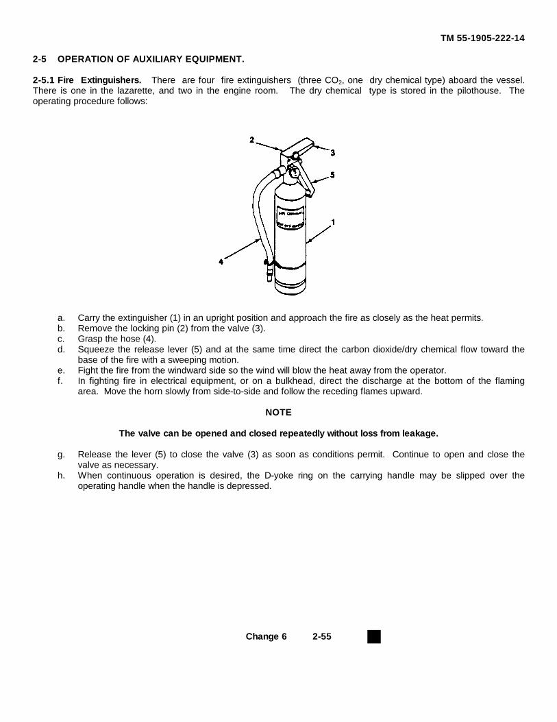
TM 55-1905-222-14
2-5 OPERATION OF AUXILIARY EQUIPMENT.
2-5.1 Fire Extinguishers. There are four fire extinguishers (three CO2, one dry chemical type) aboard the vessel.There is one in the lazarette, and two in the engine room. The dry chemical type is stored in the pilothouse. Theoperating procedure follows:
a. Carry the extinguisher (1) in an upright position and approach the fire as closely as the heat permits.b. Remove the locking pin (2) from the valve (3).c. Grasp the hose (4).d. Squeeze the release lever (5) and at the same time direct the carbon dioxide/dry chemical flow toward the
base of the fire with a sweeping motion.e. Fight the fire from the windward side so the wind will blow the heat away from the operator.f. In fighting fire in electrical equipment, or on a bulkhead, direct the discharge at the bottom of the flaming
area. Move the horn slowly from side-to-side and follow the receding flames upward.
NOTE
The valve can be opened and closed repeatedly without loss from leakage.
g. Release the lever (5) to close the valve (3) as soon as conditions permit. Continue to open and close thevalve as necessary.
h. When continuous operation is desired, the D-yoke ring on the carrying handle may be slipped over theoperating handle when the handle is depressed.
Change 6 2-55
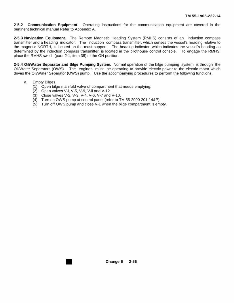
TM 55-1905-222-14
2-5.2 Communication Equipment. Operating instructions for the communication equipment are covered in thepertinent technical manual Refer to Appendix A.
2-5.3 Navigation Equipment. The Remote Magnetic Heading System (RMHS) consists of an induction compasstransmitter and a heading indicator. The induction compass transmitter, which senses the vessel's heading relative tothe magnetic NORTH, is located on the mast support. The heading indicator, which indicates the vessel's heading asdetermined by the induction compass transmitter, is located in the pilothouse control console. To engage the RMHS,place the RMHS switch (para 2-1, item 38) to the ON position.
2-5.4 Oil/Water Separator and Bilge Pumping System. Normal operation of the bilge pumping system is through theOil/Water Separators (OWS). The engines must be operating to provide electric power to the electric motor whichdrives the Oil/Water Separator (OWS) pump. Use the accompanying procedures to perform the following functions.
a. Empty Bilges.(1) Open bilge manifold valve of compartment that needs emptying.(2) Open valves V-l, V-5, V-9, V-ll and V-12.(3) Close valves V-2, V-3, V-4, V-6, V-7 and V-10.(4) Turn on OWS pump at control panel (refer to TM 55-2090-201-14&P).(5) Turn off OWS pump and close V-1 when the bilge compartment is empty.
Change 6 2-56
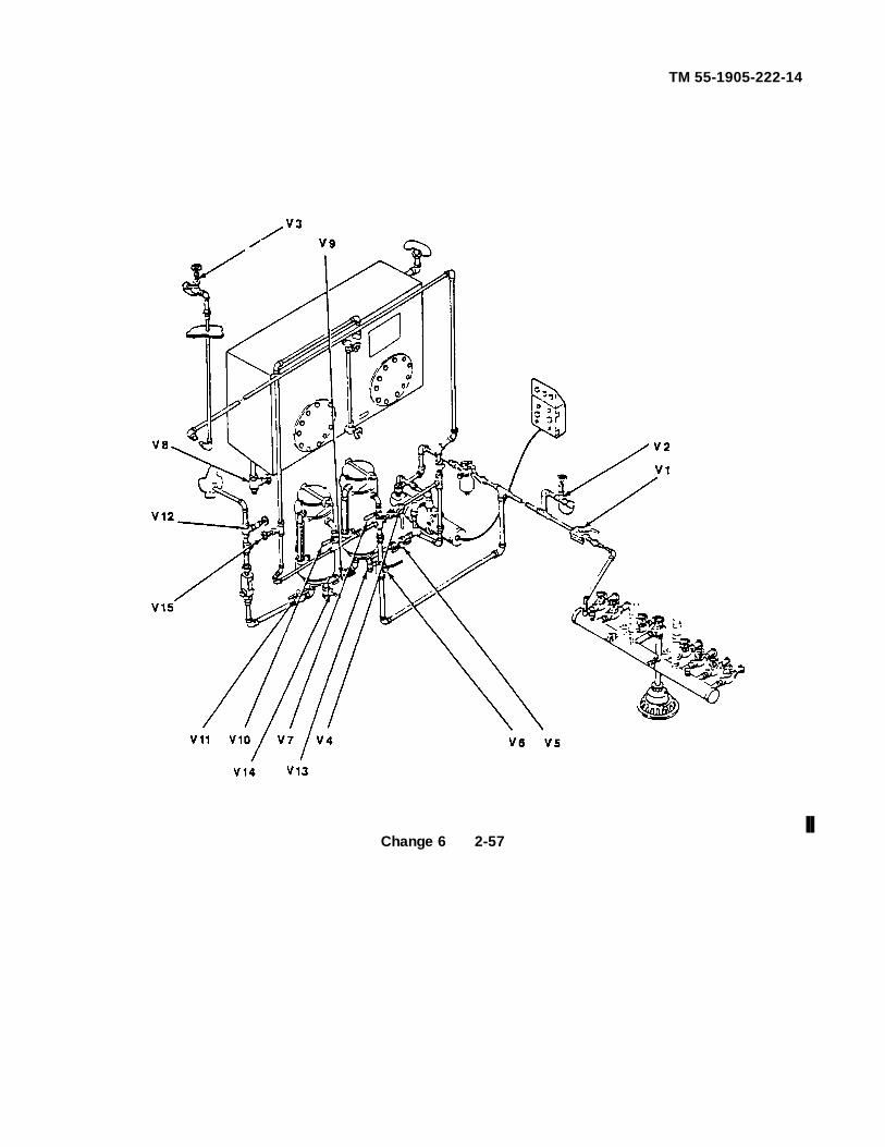
TM 55-1905-222-14
Change 6 2-57
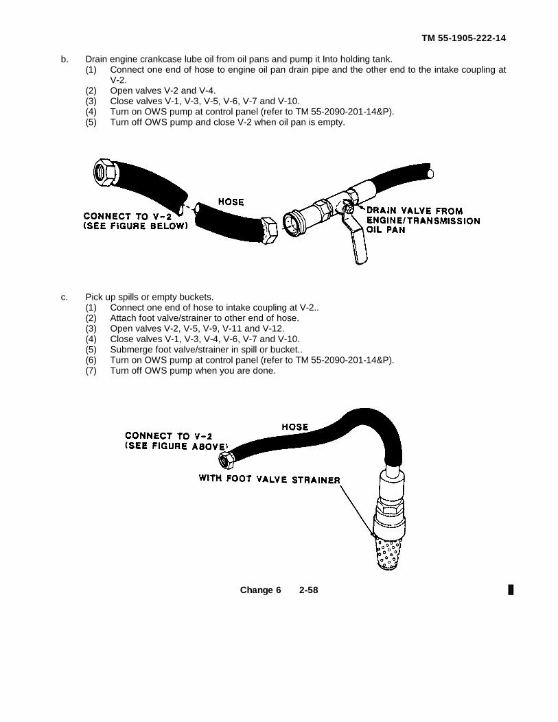
TM 55-1905-222-14
b. Drain engine crankcase lube oil from oil pans and pump it Into holding tank.(1) Connect one end of hose to engine oil pan drain pipe and the other end to the intake coupling at
V-2.(2) Open valves V-2 and V-4.(3) Close valves V-1, V-3, V-5, V-6, V-7 and V-10.(4) Turn on OWS pump at control panel (refer to TM 55-2090-201-14&P).(5) Turn off OWS pump and close V-2 when oil pan is empty.
c. Pick up spills or empty buckets.(1) Connect one end of hose to intake coupling at V-2..(2) Attach foot valve/strainer to other end of hose.(3) Open valves V-2, V-5, V-9, V-11 and V-12.(4) Close valves V-1, V-3, V-4, V-6, V-7 and V-10.(5) Submerge foot valve/strainer in spill or bucket..(6) Turn on OWS pump at control panel (refer to TM 55-2090-201-14&P).(7) Turn off OWS pump when you are done.
Change 6 2-58
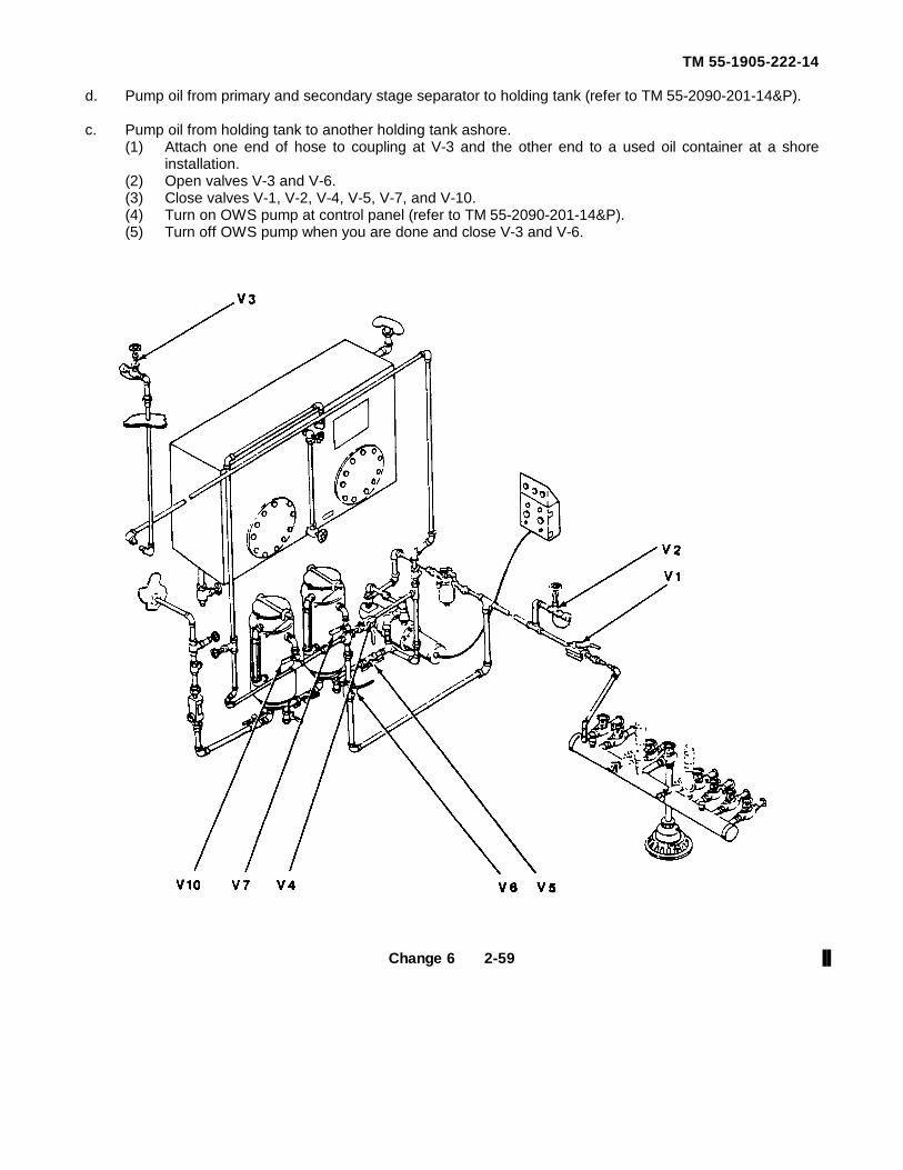
TM 55-1905-222-14
d. Pump oil from primary and secondary stage separator to holding tank (refer to TM 55-2090-201-14&P).
c. Pump oil from holding tank to another holding tank ashore.(1) Attach one end of hose to coupling at V-3 and the other end to a used oil container at a shore
installation.(2) Open valves V-3 and V-6.(3) Close valves V-1, V-2, V-4, V-5, V-7, and V-10.(4) Turn on OWS pump at control panel (refer to TM 55-2090-201-14&P).(5) Turn off OWS pump when you are done and close V-3 and V-6.
Change 6 2-59
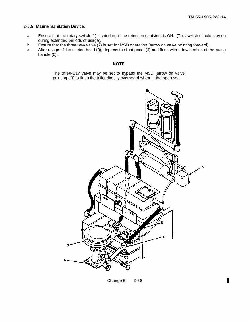
TM 55-1905-222-14
2-5.5 Marine Sanitation Device.
a. Ensure that the rotary switch (1) located near the retention canisters is ON. (This switch should stay onduring extended periods of usage).
b. Ensure that the three-way valve (2) is set for MSD operation (arrow on valve pointing forward).c. After usage of the marine head (3), depress the foot pedal (4) and flush with a few strokes of the pump
handle (5).
NOTE
The three-way valve may be set to bypass the MSD (arrow on valvepointing aft) to flush the toilet directly overboard when In the open sea.
Change 6 2-60
TM 55-1905-222-14
Section IV. OPERATING UNDER UNUSUAL CONDITIONS
2-6 COLD WEATHER OPERATION.
2-6.1 Starting Aid.
WARNING
Do not overuse starting aid. Overloading the engine air box withthis highly volatile fluid may result In an explosion.
a. Spray starting aid from aerosol can into engine air box. Follow manufacturer's instructionsb. Wait 3 seconds and then push ENG START button to start engine.
2-6.2 Engines. Keep engine compartment as warm as possible without shutting off ventilation completely.
2-6.3 Batteries.
a. Keep batteries fully charged to prevent freezing.b. Check specific gravity and adjust to suit particular conditions (TM 9-6140-200-15).c. Check batteries for correct terminal voltage.
2-6.4 Cooling System. Add antifreeze to engine fresh water cooling system to prevent freezing (TB 750-651).
2-6.5 Lubricating Oil. Refer to LO 5-2815-231-12 for instructions concerning lubrication of engines duringoperation in cold weather.
WARNING
Never use a blow torch or other similar means for heating fuel orlubricating lines.
2-6.6 Steering System. Test steering system thoroughly by moving steering wheel from left to right. Turnsteering wheel slowly at first to loosen any ice that may have formed between the hull and rudders at waterline.
2-6.7 Hull and Fittings.
a. Keep caps installed on hose connections, except when filling.b Remove Ice from ladders and passageways on main deck.
2-6.8 Navigation Lights and Horn. Ice may form on any of these units and prevent proper operation.Carefully remove ice from unit.
Change 6 2-61
TM 55-1905-222-14
2-7 HOT WEATHER OPERATION.
WARNING
Fuel oil and other similar materials are highly volatile In hotweather and these vapors increase the possibility of anexplosion. Be sure all spilled petroleum products are wiped up.Inspect for leaks in fuel lines and fittings. Pump bilges regularly.
2-7.1 Engines. Keep engine compartment as cool as possible by use of ventilation fans.
2-7.2 Batteries.
a Check electrolyte level often and fill as necessary.b Keep terminals free of corrosion.c. Reduce specific gravity (TM 9-6140-200-14)
2-7.3 Cooling System. Check water temperature gauge often Temperature should not rise above 185F(74C). If this temperature is exceeded, check for the following:
a. Insufficient supply of fresh water in the engine cooling system. If so, fill expansion tank and check forleakage.
b. Engine coolant thermostat faulty. Refer to TM 5-2815-231-14.c. Sea water (raw water) inlet clogged at sea chest Blow out sea chest with compressed aird. Engine fresh water pump faulty Refer to TM 5-2815-231-14.
2-7.4 Lubricating Oil.
a. Check lubricating oil pressure gauge often. Pressure will drop slightly as water temperature rises.b. Refer to LO 55-2815-231-14 for instructions concerning lubrication of engines during operation in hot
weather.
2-8 FOUL WEATHER OPERATION.
a. Check to see that all gear and equipment are properly stowed and secured.b Should the engines be operated at high speed in rough water, the engines will surge when the
propellers leave the water, causing excessive vibration. The governor may be overworked under theseconditions, and it will be necessary for the protection of the engines and safety of the vessel to reducethe speed of the engines until a safe operating speed is attained, as determined by the state of the sea.
Change 6 2-62
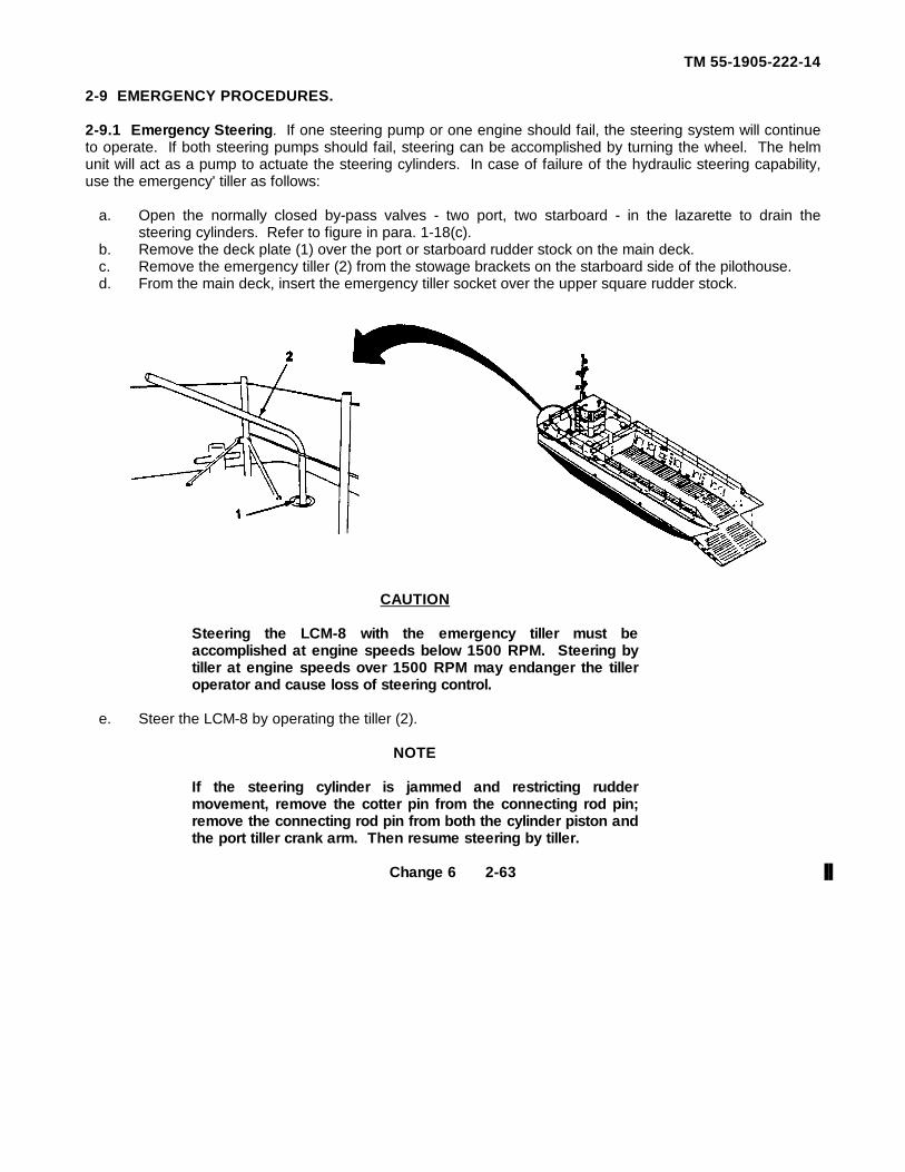
TM 55-1905-222-14
2-9 EMERGENCY PROCEDURES.
2-9.1 Emergency Steering. If one steering pump or one engine should fail, the steering system will continueto operate. If both steering pumps should fail, steering can be accomplished by turning the wheel. The helmunit will act as a pump to actuate the steering cylinders. In case of failure of the hydraulic steering capability,use the emergency' tiller as follows:
a. Open the normally closed by-pass valves - two port, two starboard - in the lazarette to drain thesteering cylinders. Refer to figure in para. 1-18(c).
b. Remove the deck plate (1) over the port or starboard rudder stock on the main deck.c. Remove the emergency tiller (2) from the stowage brackets on the starboard side of the pilothouse.d. From the main deck, insert the emergency tiller socket over the upper square rudder stock.
CAUTION
Steering the LCM-8 with the emergency tiller must beaccomplished at engine speeds below 1500 RPM. Steering bytiller at engine speeds over 1500 RPM may endanger the tilleroperator and cause loss of steering control.
e. Steer the LCM-8 by operating the tiller (2).
NOTE
If the steering cylinder is jammed and restricting ruddermovement, remove the cotter pin from the connecting rod pin;remove the connecting rod pin from both the cylinder piston andthe port tiller crank arm. Then resume steering by tiller.
Change 6 2-63
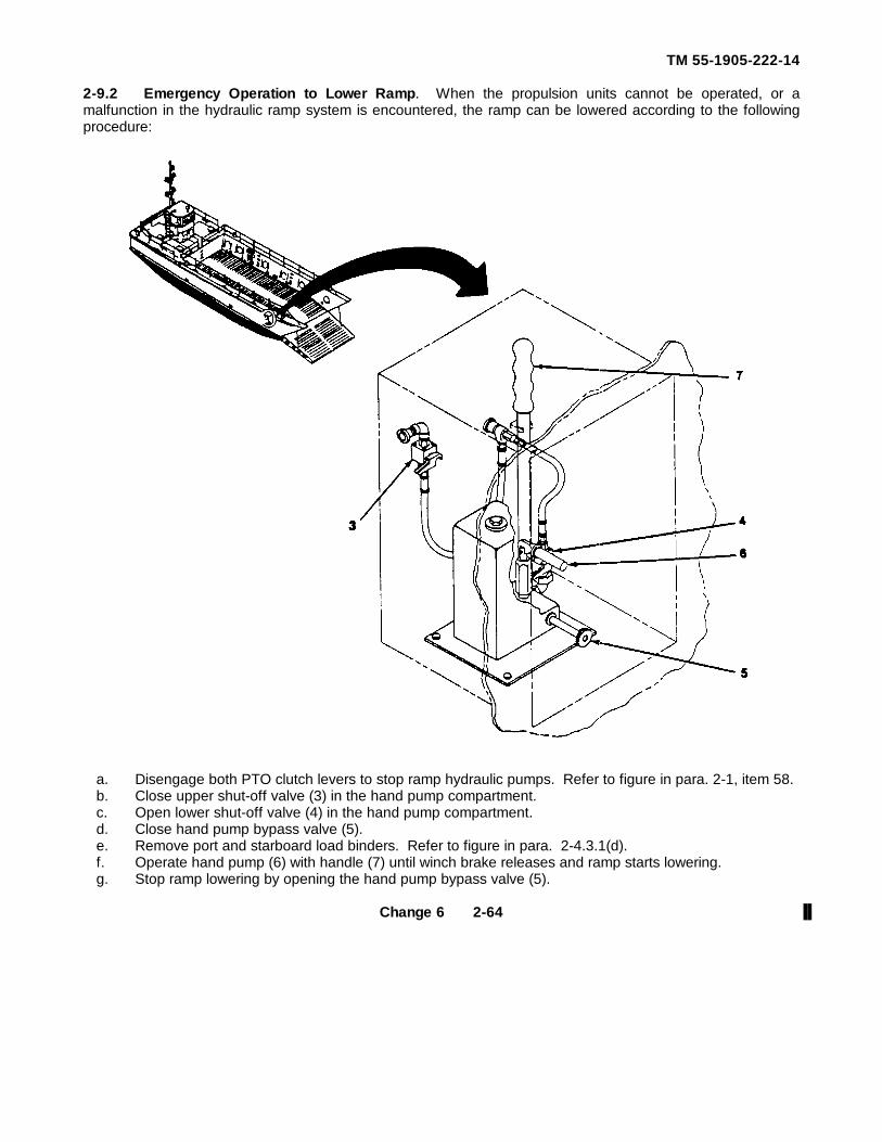
TM 55-1905-222-14
2-9.2 Emergency Operation to Lower Ramp. When the propulsion units cannot be operated, or amalfunction in the hydraulic ramp system is encountered, the ramp can be lowered according to the followingprocedure:
a. Disengage both PTO clutch levers to stop ramp hydraulic pumps. Refer to figure in para. 2-1, item 58.b. Close upper shut-off valve (3) in the hand pump compartment.c. Open lower shut-off valve (4) in the hand pump compartment.d. Close hand pump bypass valve (5).e. Remove port and starboard load binders. Refer to figure in para. 2-4.3.1(d).f. Operate hand pump (6) with handle (7) until winch brake releases and ramp starts lowering.g. Stop ramp lowering by opening the hand pump bypass valve (5).
Change 6 2-64
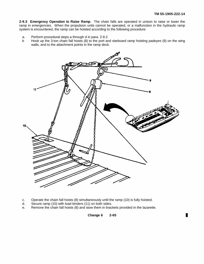
TM 55-1905-222-14
2-9.3 Emergency Operation to Raise Ramp. The chain falls are operated in unison to raise or lower theramp in emergencies. When the propulsion units cannot be operated, or a malfunction in the hydraulic rampsystem is encountered, the ramp can be hoisted according to the following procedure:
a. Perform procedural steps a through d in para. 2-9.2.b Hook up the 3-ton chain fall hoists (8) to the port and starboard ramp hoisting padeyes (9) on the wing
walls, and to the attachment points in the ramp deck.
c. Operate the chain fall hoists (8) simultaneously until the ramp (10) is fully hoisted.d. Secure ramp (10) with load binders (11) on both sides.e. Remove the chain fall hoists (8) and stow them in brackets provided in the lazarette.
Change 6 2-65
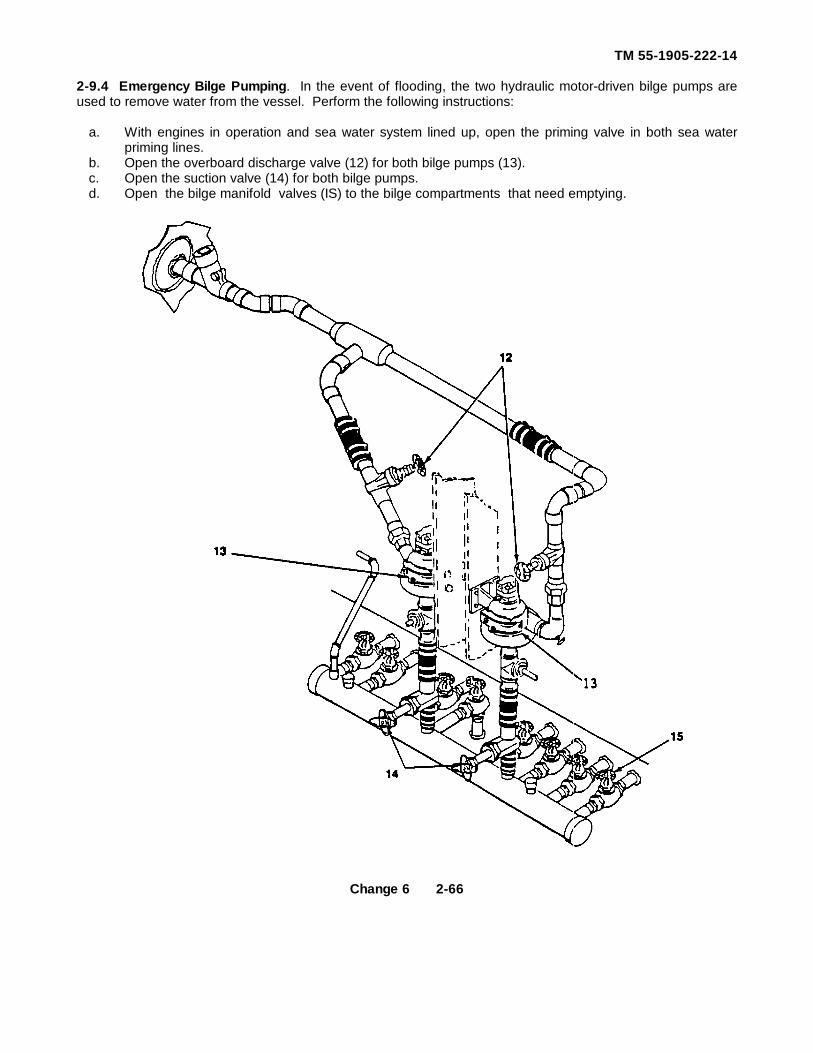
TM 55-1905-222-14
2-9.4 Emergency Bilge Pumping. In the event of flooding, the two hydraulic motor-driven bilge pumps areused to remove water from the vessel. Perform the following instructions:
a. With engines in operation and sea water system lined up, open the priming valve in both sea waterpriming lines.
b. Open the overboard discharge valve (12) for both bilge pumps (13).c. Open the suction valve (14) for both bilge pumps.d. Open the bilge manifold valves (IS) to the bilge compartments that need emptying.
Change 6 2-66
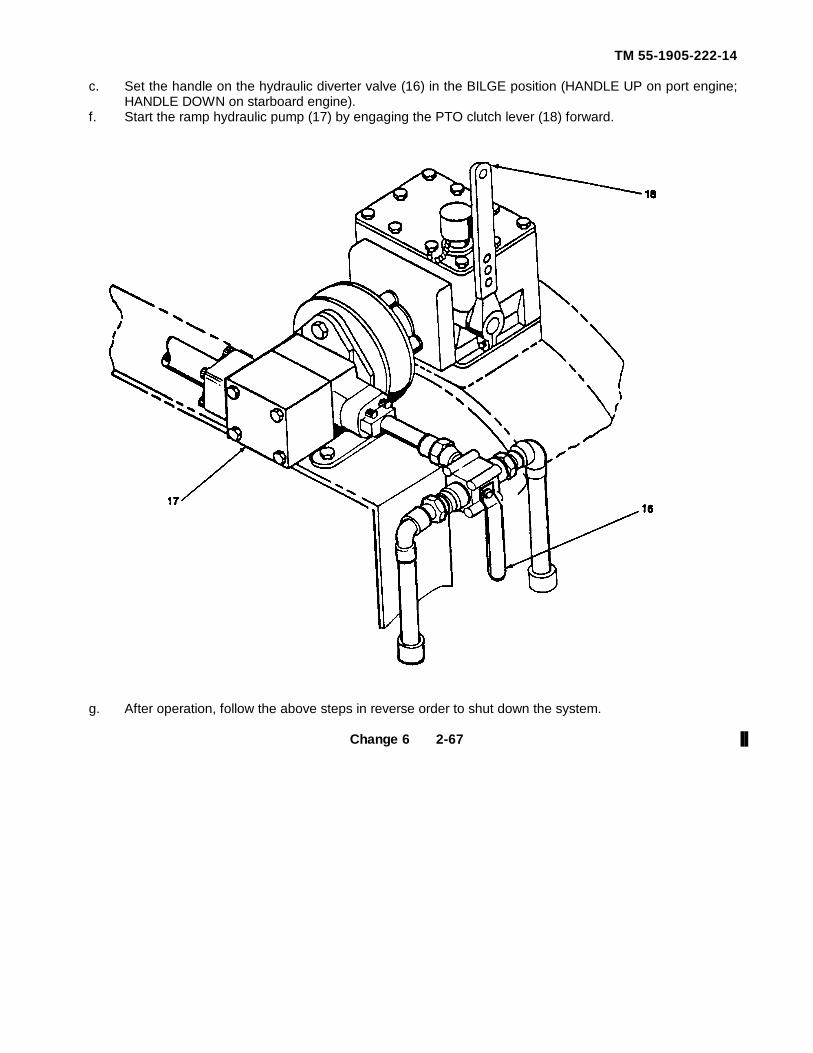
TM 55-1905-222-14
c. Set the handle on the hydraulic diverter valve (16) in the BILGE position (HANDLE UP on port engine;HANDLE DOWN on starboard engine).
f. Start the ramp hydraulic pump (17) by engaging the PTO clutch lever (18) forward.
g. After operation, follow the above steps in reverse order to shut down the system.
Change 6 2-67
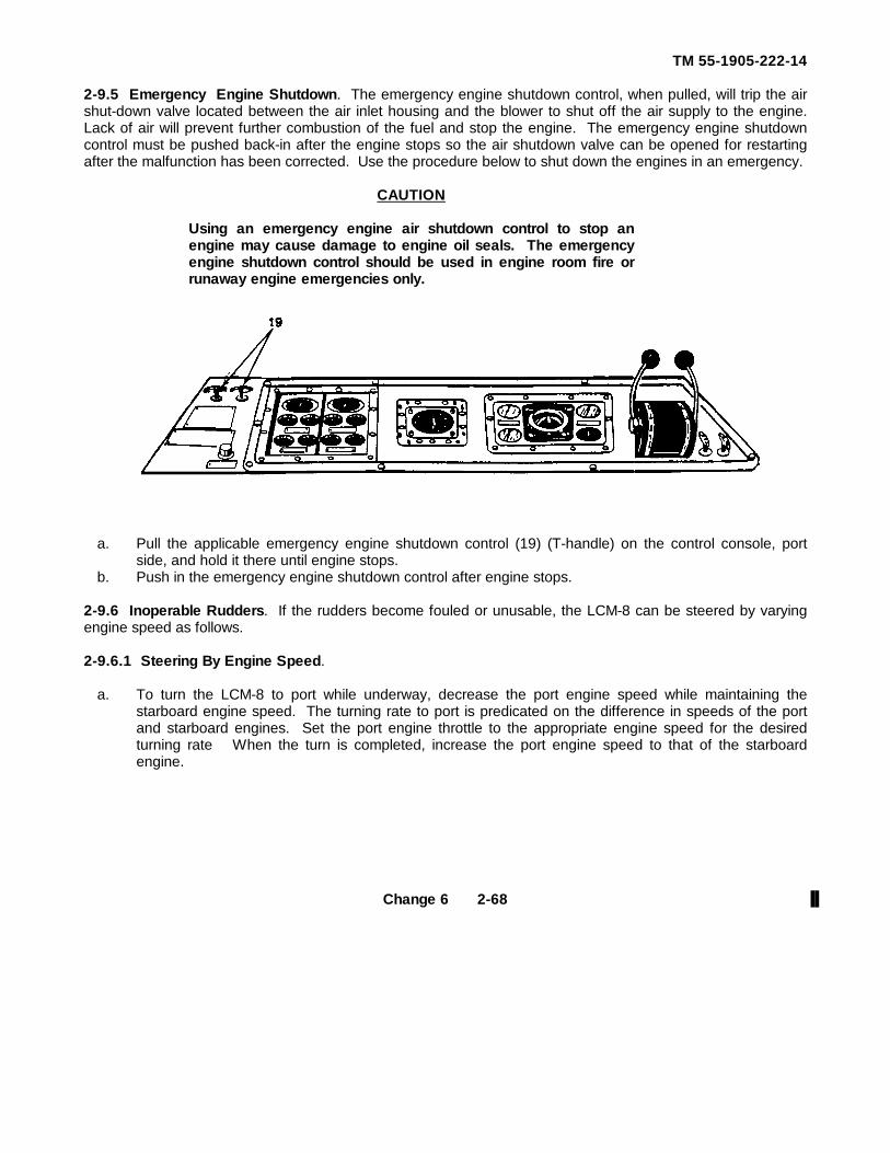
TM 55-1905-222-14
2-9.5 Emergency Engine Shutdown. The emergency engine shutdown control, when pulled, will trip the airshut-down valve located between the air inlet housing and the blower to shut off the air supply to the engine.Lack of air will prevent further combustion of the fuel and stop the engine. The emergency engine shutdowncontrol must be pushed back-in after the engine stops so the air shutdown valve can be opened for restartingafter the malfunction has been corrected. Use the procedure below to shut down the engines in an emergency.
CAUTION
Using an emergency engine air shutdown control to stop anengine may cause damage to engine oil seals. The emergencyengine shutdown control should be used in engine room fire orrunaway engine emergencies only.
a. Pull the applicable emergency engine shutdown control (19) (T-handle) on the control console, portside, and hold it there until engine stops.
b. Push in the emergency engine shutdown control after engine stops.
2-9.6 Inoperable Rudders. If the rudders become fouled or unusable, the LCM-8 can be steered by varyingengine speed as follows.
2-9.6.1 Steering By Engine Speed.
a. To turn the LCM-8 to port while underway, decrease the port engine speed while maintaining thestarboard engine speed. The turning rate to port is predicated on the difference in speeds of the portand starboard engines. Set the port engine throttle to the appropriate engine speed for the desiredturning rate When the turn is completed, increase the port engine speed to that of the starboardengine.
Change 6 2-68
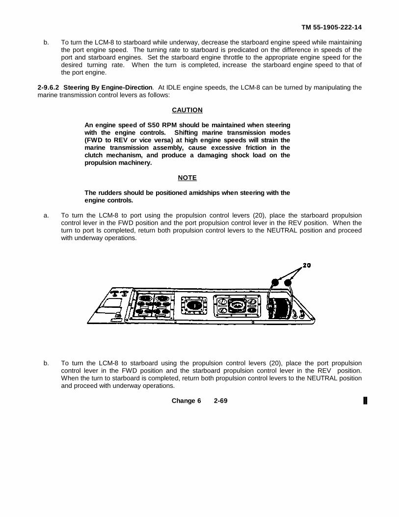
TM 55-1905-222-14
b. To turn the LCM-8 to starboard while underway, decrease the starboard engine speed while maintainingthe port engine speed. The turning rate to starboard is predicated on the difference in speeds of theport and starboard engines. Set the starboard engine throttle to the appropriate engine speed for thedesired turning rate. When the turn is completed, increase the starboard engine speed to that ofthe port engine.
2-9.6.2 Steering By Engine-Direction. At IDLE engine speeds, the LCM-8 can be turned by manipulating themarine transmission control levers as follows:
CAUTION
An engine speed of S50 RPM should be maintained when steeringwith the engine controls. Shifting marine transmission modes(FWD to REV or vice versa) at high engine speeds will strain themarine transmission assembly, cause excessive friction in theclutch mechanism, and produce a damaging shock load on thepropulsion machinery.
NOTE
The rudders should be positioned amidships when steering with theengine controls.
a. To turn the LCM-8 to port using the propulsion control levers (20), place the starboard propulsioncontrol lever in the FWD position and the port propulsion control lever in the REV position. When theturn to port Is completed, return both propulsion control levers to the NEUTRAL position and proceedwith underway operations.
b. To turn the LCM-8 to starboard using the propulsion control levers (20), place the port propulsioncontrol lever in the FWD position and the starboard propulsion control lever in the REV position.When the turn to starboard is completed, return both propulsion control levers to the NEUTRAL positionand proceed with underway operations.
Change 6 2-69
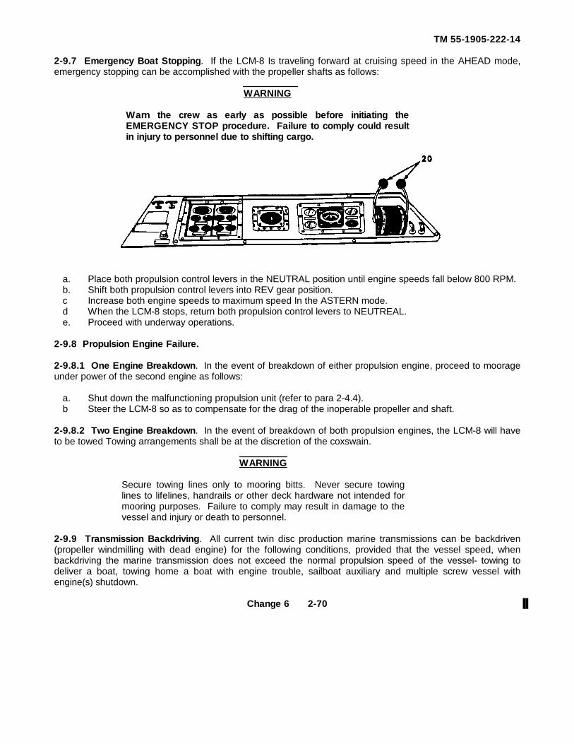
TM 55-1905-222-14
2-9.7 Emergency Boat Stopping. If the LCM-8 Is traveling forward at cruising speed in the AHEAD mode,emergency stopping can be accomplished with the propeller shafts as follows:
WARNING
Warn the crew as early as possible before initiating theEMERGENCY STOP procedure. Failure to comply could resultin injury to personnel due to shifting cargo.
a. Place both propulsion control levers in the NEUTRAL position until engine speeds fall below 800 RPM.b. Shift both propulsion control levers into REV gear position.c Increase both engine speeds to maximum speed In the ASTERN mode.d When the LCM-8 stops, return both propulsion control levers to NEUTREAL.e. Proceed with underway operations.
2-9.8 Propulsion Engine Failure.
2-9.8.1 One Engine Breakdown. In the event of breakdown of either propulsion engine, proceed to moorageunder power of the second engine as follows:
a. Shut down the malfunctioning propulsion unit (refer to para 2-4.4).b Steer the LCM-8 so as to compensate for the drag of the inoperable propeller and shaft.
2-9.8.2 Two Engine Breakdown. In the event of breakdown of both propulsion engines, the LCM-8 will haveto be towed Towing arrangements shall be at the discretion of the coxswain.
WARNING
Secure towing lines only to mooring bitts. Never secure towinglines to lifelines, handrails or other deck hardware not intended formooring purposes. Failure to comply may result in damage to thevessel and injury or death to personnel.
2-9.9 Transmission Backdriving. All current twin disc production marine transmissions can be backdriven(propeller windmilling with dead engine) for the following conditions, provided that the vessel speed, whenbackdriving the marine transmission does not exceed the normal propulsion speed of the vessel- towing todeliver a boat, towing home a boat with engine trouble, sailboat auxiliary and multiple screw vessel withengine(s) shutdown.
Change 6 2-70
TM 55-1905-222-14
2-9.9.1 Selective Methods Required for Backdriving.
a. Start the engine and operate the marine transmission in neutral at normal fluid pressures for aminimum of five minutes, doing this once every eight hours. Maintain the backdnven marinetransmission's oil level at the full mark on the dipstick.
b. In the case of an inoperable engine where pressure lubing the transmission is not possible, plug thedipstick tube and fill the unit with oil. Then, before backdnving, drain the oil down to full oil level.Repeat this process every eight hours.
Change 6 2-71/(2-72 blank)
TM 55-1905-222-14
2-9.9.1 Selective Methods Required for Backdriving.
a Start the engine and operate the marine transmission In neutral at normal fluid pressures for aminimum of five minutes, doing this once every eight hours Maintain the backdriven marinetransmissions oil level at the full mark on the dipstick.
b. In the case of an Inoperable engine where pressure lubing the transmission is not possible, plug thedipstick tube and fill the unit with oil. Then, before backdriving, drain the oil down to full oil level.Repeat this process every eight hours.
Change 3 2-72.1/(2-72.2 blank)
CHAPTER 3
OPERATOR MAINTENANCE
Paragraph
Adjust Stuffing Box .................................................................................................................3-18
Functional Test of Alternator ...................................................................................................3-5
General Maintenance Procedures. ..........................................................................................3-3
General Lubrication Instructions..............................................................................................3-1
Inspect Ramp System Reservoir, Strainers and Filters............................................................3-8
Inspect Sanitation System ......................................................................................................3-6
Inspect Steering System Reservoir, Strainers and Filter..........................................................3-10
Replace Fuel Filter/Water Separator .......................................................................................3-17
Replace Fuel Strainer .............................................................................................................3-15
Replace Navigation Light Bulb and Lens Housing. ..................................................................3-4
Service Fuel Filter/Water Separator........................................................................................3-16
Service Fuel Strainer ..............................................................................................................3-14
Service Ramp System Reservoir, Strainers, and Filters ..........................................................3-9
Service Sanitation System . ....................................................................................................3-7
Service Sea Water Strainers .................................................................................................3-12
Service Starting System Reservoir and Filters ........................................................................3-13
Service Steering System Reservoir, Strainers and Filters........................................................3-11
Troubleshooting Procedures....................................................................................................3-2
3-1
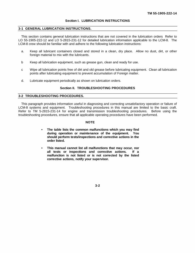
TM 55-1905-222-14
Section I. LUBRICATION INSTRUCTIONS
3-1 GENERAL LUBRICATION INSTRUCTIONS.
This section contains general lubrication instructions that are not covered in the lubrication orders Refer toLO 55-1905-222-12 and LO 5-2815-231-12 for detailed lubrication information applicable to the LCM-8. TheLCM-8 crew should be familiar with and adhere to the following lubrication instructions:
a. Keep all lubricant containers closed and stored in a clean, dry place. Allow no dust, dirt, or otherforeign material to mix with the lubricants.
b Keep all lubrication equipment, such as grease gun, clean and ready for use.
c Wipe all lubrication points free of dirt and old grease before lubricating equipment. Clean all lubricationpoints after lubricating equipment to prevent accumulation of Foreign matter.
d. Lubricate equipment periodically as shown on lubrication orders.
Section II. TROUBLESHOOTING PROCEDURES
3-2 TROUBLESHOOTING PROCEDURES.
This paragraph provides information useful in diagnosing and correcting unsatisfactory operation or failure ofLCM-8 systems and equipment. Troubleshooting procedures in this manual are limited to the basic craft.Refer to TM 5-2815-231-14 for engine and transmission troubleshooting procedures. Before using thetroubleshooting procedures, ensure that all applicable operating procedures have been performed.
NOTE
· The table lists the common malfunctions which you may findduring operation or maintenance of the equipment. Youshould perform tests/inspections and corrective actions in theorder listed.
· This manual cannot list all malfunctions that may occur, nor
all tests or inspections and corrective actions. If amalfunction is not listed or is not corrected by the listedcorrective actions, notify your supervisor.
3-2
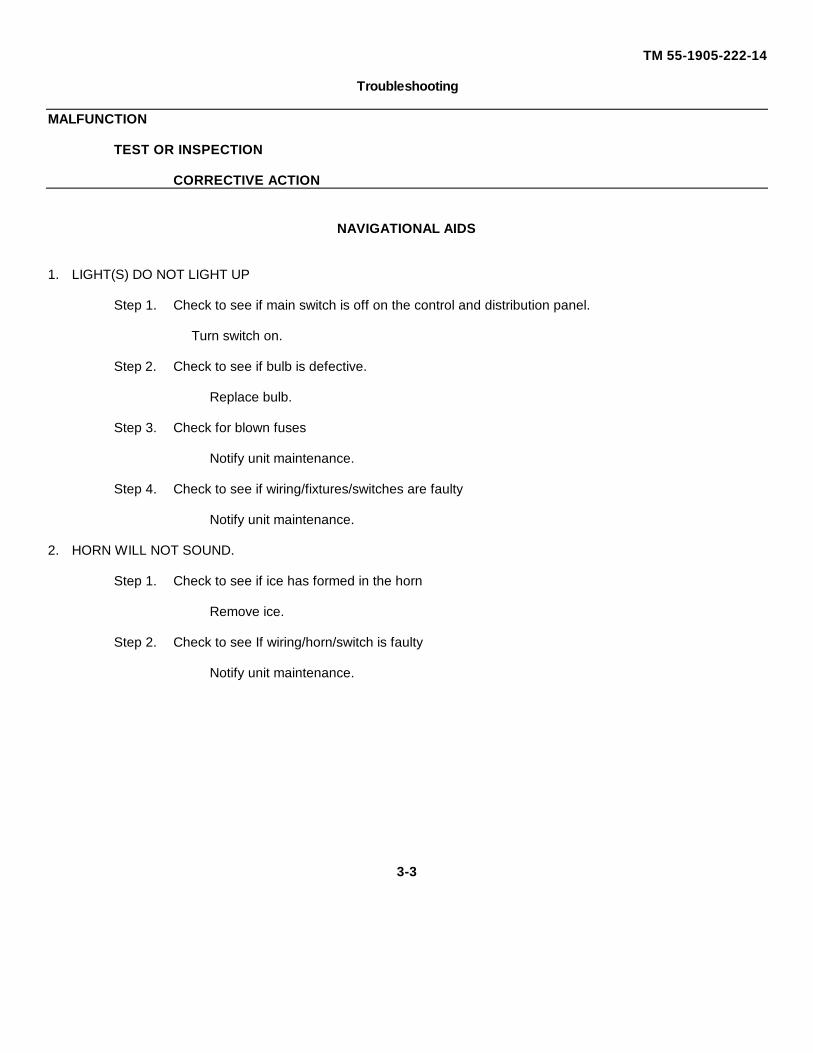
TM 55-1905-222-14
Troubleshooting
MALFUNCTION
TEST OR INSPECTION
CORRECTIVE ACTION
NAVIGATIONAL AIDS
1. LIGHT(S) DO NOT LIGHT UP
Step 1. Check to see if main switch is off on the control and distribution panel.
Turn switch on.
Step 2. Check to see if bulb is defective.
Replace bulb.
Step 3. Check for blown fuses
Notify unit maintenance.
Step 4. Check to see if wiring/fixtures/switches are faulty
Notify unit maintenance.
2. HORN WILL NOT SOUND.
Step 1. Check to see if ice has formed in the horn
Remove ice.
Step 2. Check to see If wiring/horn/switch is faulty
Notify unit maintenance.
3-3
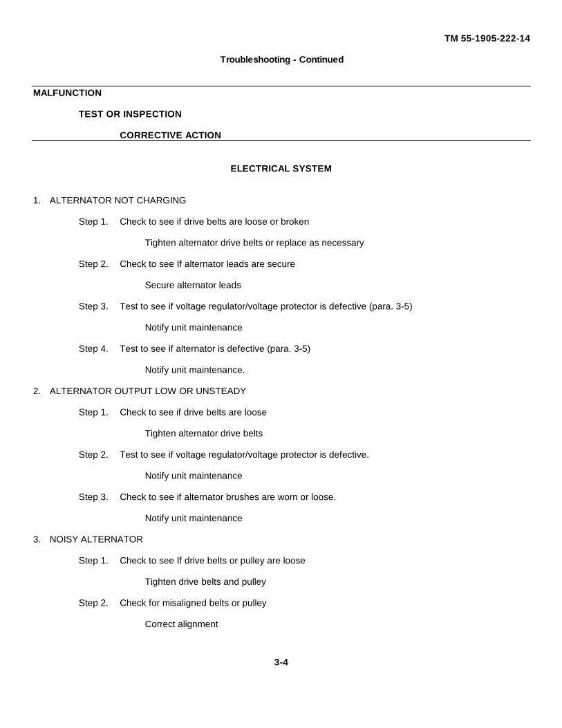
TM 55-1905-222-14
Troubleshooting - Continued
MALFUNCTION
TEST OR INSPECTION
CORRECTIVE ACTION
ELECTRICAL SYSTEM
1. ALTERNATOR NOT CHARGING
Step 1. Check to see if drive belts are loose or broken
Tighten alternator drive belts or replace as necessary
Step 2. Check to see If alternator leads are secure
Secure alternator leads
Step 3. Test to see if voltage regulator/voltage protector is defective (para. 3-5)
Notify unit maintenance
Step 4. Test to see if alternator is defective (para. 3-5)
Notify unit maintenance.
2. ALTERNATOR OUTPUT LOW OR UNSTEADY
Step 1. Check to see if drive belts are loose
Tighten alternator drive belts
Step 2. Test to see if voltage regulator/voltage protector is defective.
Notify unit maintenance
Step 3. Check to see if alternator brushes are worn or loose.
Notify unit maintenance
3. NOISY ALTERNATOR
Step 1. Check to see If drive belts or pulley are loose
Tighten drive belts and pulley
Step 2. Check for misaligned belts or pulley
Correct alignment
3-4
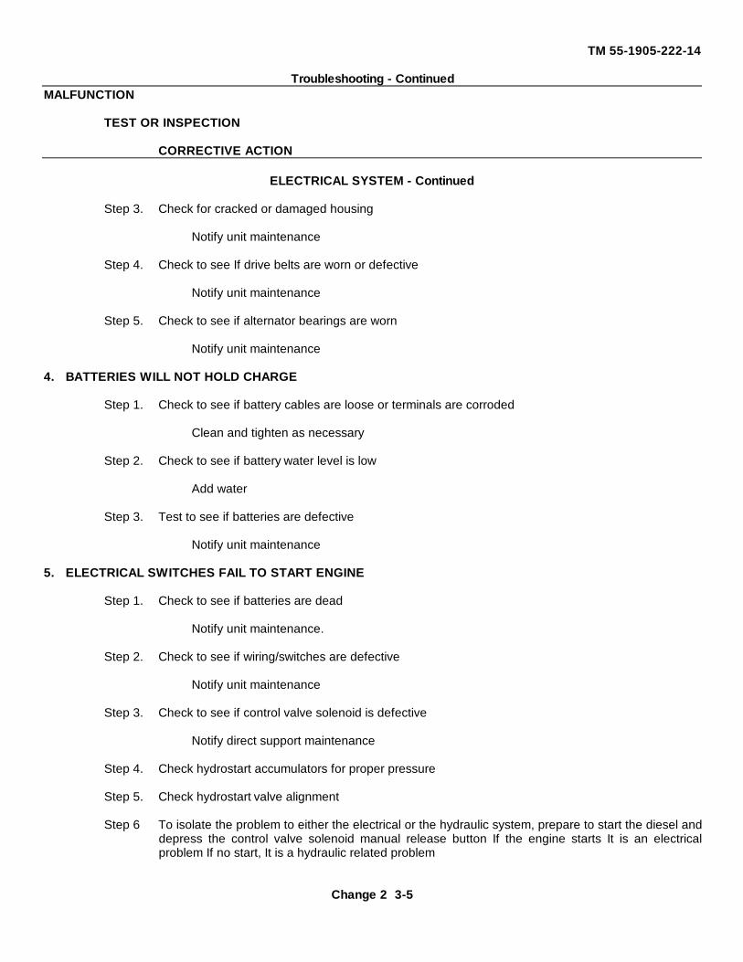
TM 55-1905-222-14
Troubleshooting - ContinuedMALFUNCTION
TEST OR INSPECTION
CORRECTIVE ACTION
ELECTRICAL SYSTEM - Continued
Step 3. Check for cracked or damaged housing
Notify unit maintenance
Step 4. Check to see If drive belts are worn or defective
Notify unit maintenance
Step 5. Check to see if alternator bearings are worn
Notify unit maintenance
4. BATTERIES WILL NOT HOLD CHARGE
Step 1. Check to see if battery cables are loose or terminals are corroded
Clean and tighten as necessary
Step 2. Check to see if battery water level is low
Add water
Step 3. Test to see if batteries are defective
Notify unit maintenance
5. ELECTRICAL SWITCHES FAIL TO START ENGINE
Step 1. Check to see if batteries are dead
Notify unit maintenance.
Step 2. Check to see if wiring/switches are defective
Notify unit maintenance
Step 3. Check to see if control valve solenoid is defective
Notify direct support maintenance
Step 4. Check hydrostart accumulators for proper pressure
Step 5. Check hydrostart valve alignment
Step 6 To isolate the problem to either the electrical or the hydraulic system, prepare to start the diesel anddepress the control valve solenoid manual release button If the engine starts It is an electricalproblem If no start, It is a hydraulic related problem
Change 2 3-5
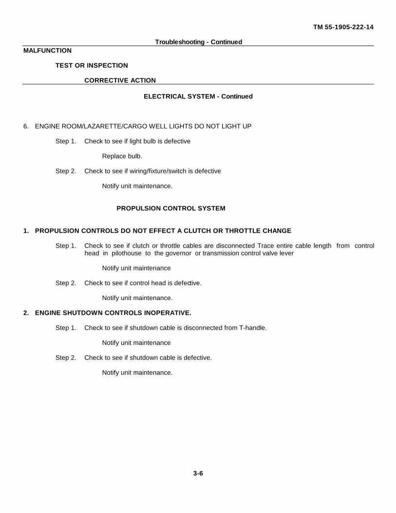
TM 55-1905-222-14
Troubleshooting - ContinuedMALFUNCTION
TEST OR INSPECTION
CORRECTIVE ACTION
ELECTRICAL SYSTEM - Continued
6. ENGINE ROOM/LAZARETTE/CARGO WELL LIGHTS DO NOT LIGHT UP
Step 1. Check to see if light bulb is defective
Replace bulb.
Step 2. Check to see if wiring/fixture/switch is defective
Notify unit maintenance.
PROPULSION CONTROL SYSTEM
1. PROPULSION CONTROLS DO NOT EFFECT A CLUTCH OR THROTTLE CHANGE
Step 1. Check to see if clutch or throttle cables are disconnected Trace entire cable length from controlhead in pilothouse to the governor or transmission control valve lever
Notify unit maintenance
Step 2. Check to see if control head is defective.
Notify unit maintenance.
2. ENGINE SHUTDOWN CONTROLS INOPERATIVE.
Step 1. Check to see if shutdown cable is disconnected from T-handle.
Notify unit maintenance
Step 2. Check to see if shutdown cable is defective.
Notify unit maintenance.
3-6
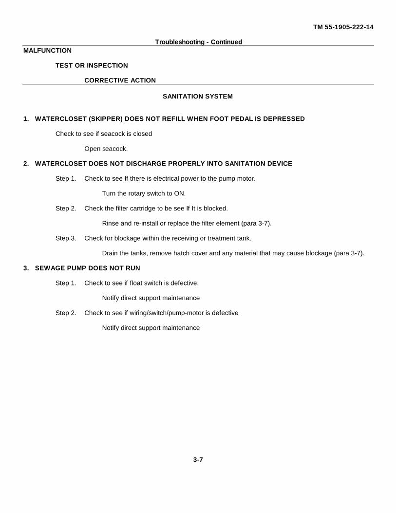
TM 55-1905-222-14
Troubleshooting - ContinuedMALFUNCTION
TEST OR INSPECTION
CORRECTIVE ACTION
SANITATION SYSTEM
1. WATERCLOSET (SKIPPER) DOES NOT REFILL WHEN FOOT PEDAL IS DEPRESSED
Check to see if seacock is closed
Open seacock.
2. WATERCLOSET DOES NOT DISCHARGE PROPERLY INTO SANITATION DEVICE
Step 1. Check to see If there is electrical power to the pump motor.
Turn the rotary switch to ON.
Step 2. Check the filter cartridge to be see If It is blocked.
Rinse and re-install or replace the filter element (para 3-7).
Step 3. Check for blockage within the receiving or treatment tank.
Drain the tanks, remove hatch cover and any material that may cause blockage (para 3-7).
3. SEWAGE PUMP DOES NOT RUN
Step 1. Check to see if float switch is defective.
Notify direct support maintenance
Step 2. Check to see if wiring/switch/pump-motor is defective
Notify direct support maintenance
3-7
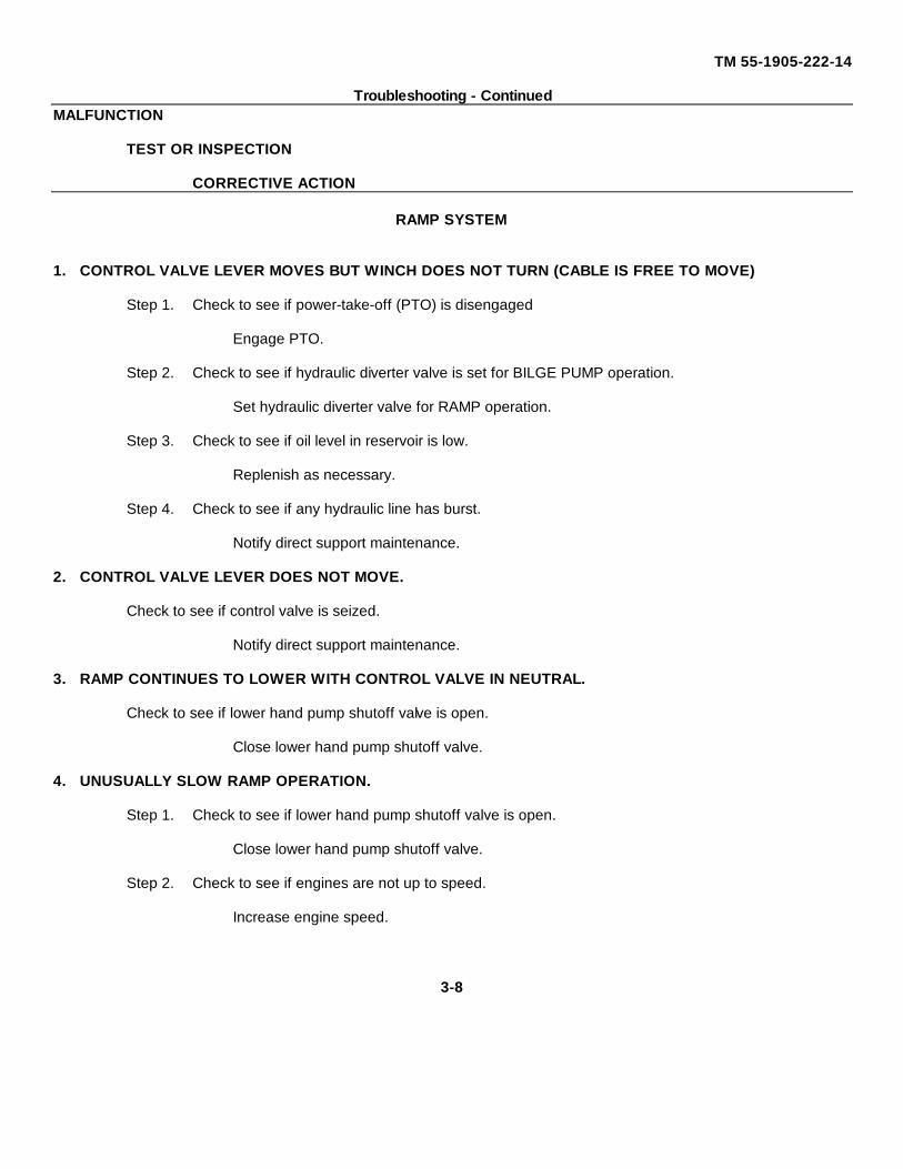
TM 55-1905-222-14
Troubleshooting - ContinuedMALFUNCTION
TEST OR INSPECTION
CORRECTIVE ACTION
RAMP SYSTEM
1. CONTROL VALVE LEVER MOVES BUT WINCH DOES NOT TURN (CABLE IS FREE TO MOVE)
Step 1. Check to see if power-take-off (PTO) is disengaged
Engage PTO.
Step 2. Check to see if hydraulic diverter valve is set for BILGE PUMP operation.
Set hydraulic diverter valve for RAMP operation.
Step 3. Check to see if oil level in reservoir is low.
Replenish as necessary.
Step 4. Check to see if any hydraulic line has burst.
Notify direct support maintenance.
2. CONTROL VALVE LEVER DOES NOT MOVE.
Check to see if control valve is seized.
Notify direct support maintenance.
3. RAMP CONTINUES TO LOWER WITH CONTROL VALVE IN NEUTRAL.
Check to see if lower hand pump shutoff valve is open.
Close lower hand pump shutoff valve.
4. UNUSUALLY SLOW RAMP OPERATION.
Step 1. Check to see if lower hand pump shutoff valve is open.
Close lower hand pump shutoff valve.
Step 2. Check to see if engines are not up to speed.
Increase engine speed.
3-8
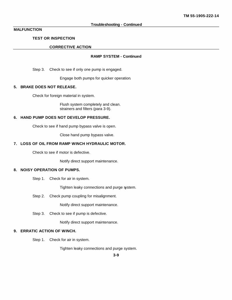
TM 55-1905-222-14
Troubleshooting - ContinuedMALFUNCTION
TEST OR INSPECTION
CORRECTIVE ACTION
RAMP SYSTEM - Continued
Step 3. Check to see if only one pump is engaged.
Engage both pumps for quicker operation.
5. BRAKE DOES NOT RELEASE.
Check for foreign material in system.
Flush system completely and clean.strainers and filters (para 3-9).
6. HAND PUMP DOES NOT DEVELOP PRESSURE.
Check to see if hand pump bypass valve is open.
Close hand pump bypass valve.
7. LOSS OF OIL FROM RAMP WINCH HYDRAULIC MOTOR.
Check to see if motor is defective.
Notify direct support maintenance.
8. NOISY OPERATION OF PUMPS.
Step 1. Check for air in system.
Tighten leaky connections and purge system.
Step 2. Check pump coupling for misalignment.
Notify direct support maintenance.
Step 3. Check to see if pump is defective.
Notify direct support maintenance.
9. ERRATIC ACTION OF WINCH.
Step 1. Check for air in system.
Tighten leaky connections and purge system.
3-9

TM 55-1905-222-14
Troubleshooting - ContinuedMALFUNCTION
TEST OR INSPECTION
CORRECTIVE ACTION
RAMP SYSTEM - Continued
Step 2. Check to see If winch is defective.
Notify general support.
STEERING SYSTEM.
1. STEERING WHEEL DIFFICULT TO TURN.
Step 1. Check to see If Isolation valves In lazarette are closed.
Open isolation valves (refer to figure In para 5-30).
Step 2. Check to see if counterbalance valve is set improperly.
Notify unit maintenance.
Step 3. Check to see if relief valve is stuck open.
Notify unit maintenance.
Step 4. Check to see if there is binding In helm unit.
Notify direct support maintenance.
Step 5. Check to see If rudder is jammed or fouled.
Notify general support maintenance.
2. STEERING IS SLOW.
Check to see if foreign material is in flow divider.
Notify direct support maintenance.
3. WHEEL TURNS BUT RUDDER DOES NOT.
Step 1. Check for air In system.
Tighten leaky connections and purge system.
3-10
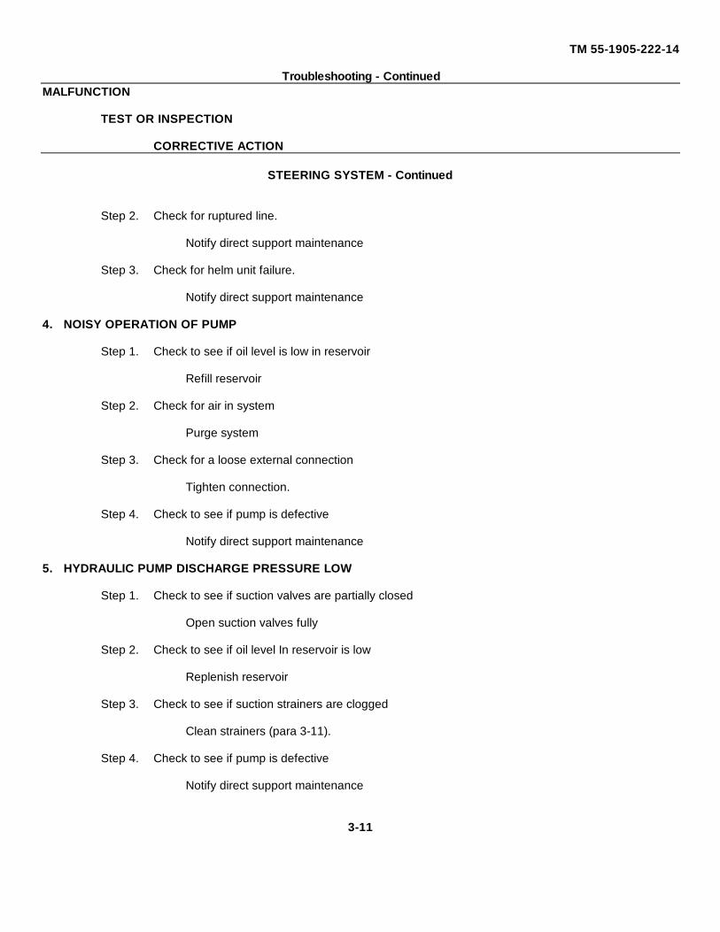
TM 55-1905-222-14
Troubleshooting - ContinuedMALFUNCTION
TEST OR INSPECTION
CORRECTIVE ACTION
STEERING SYSTEM - Continued
Step 2. Check for ruptured line.
Notify direct support maintenance
Step 3. Check for helm unit failure.
Notify direct support maintenance
4. NOISY OPERATION OF PUMP
Step 1. Check to see if oil level is low in reservoir
Refill reservoir
Step 2. Check for air in system
Purge system
Step 3. Check for a loose external connection
Tighten connection.
Step 4. Check to see if pump is defective
Notify direct support maintenance
5. HYDRAULIC PUMP DISCHARGE PRESSURE LOW
Step 1. Check to see if suction valves are partially closed
Open suction valves fully
Step 2. Check to see if oil level In reservoir is low
Replenish reservoir
Step 3. Check to see if suction strainers are clogged
Clean strainers (para 3-11).
Step 4. Check to see if pump is defective
Notify direct support maintenance
3-11
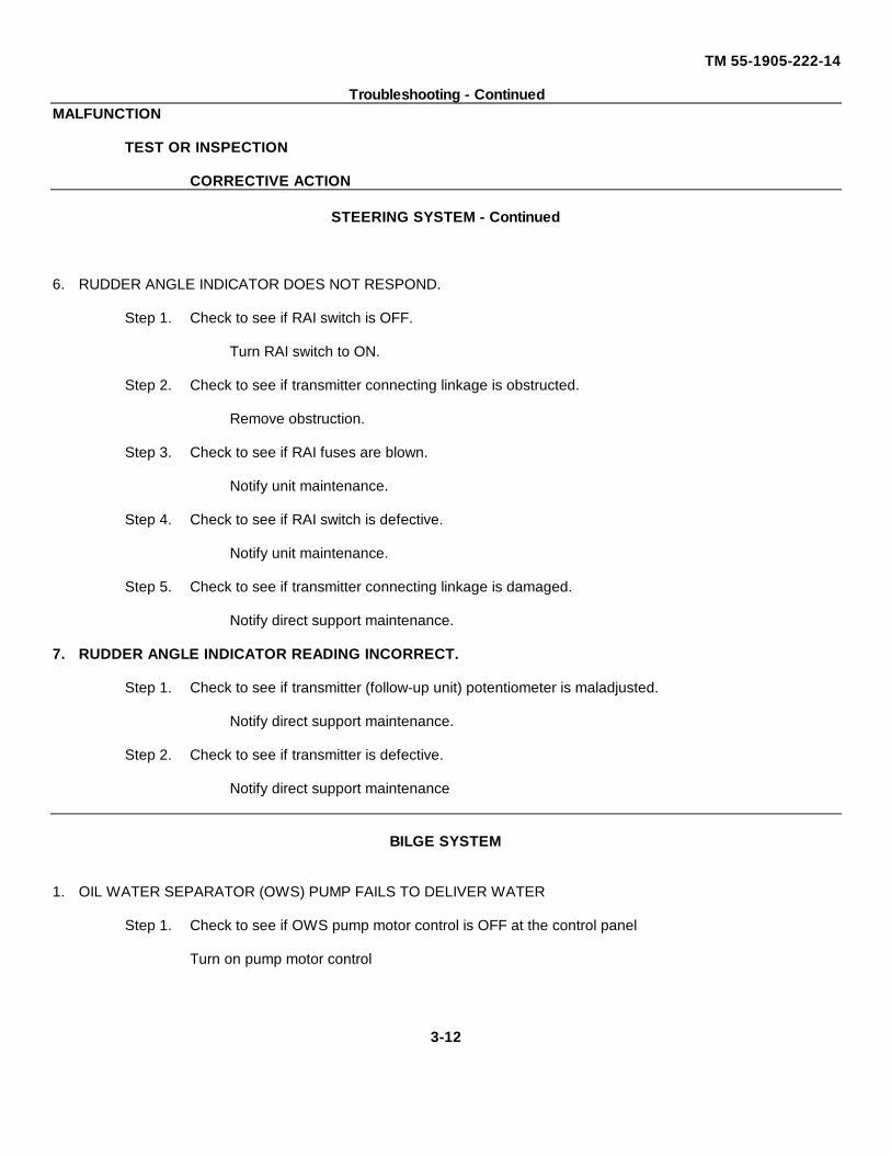
TM 55-1905-222-14
Troubleshooting - ContinuedMALFUNCTION
TEST OR INSPECTION
CORRECTIVE ACTION
STEERING SYSTEM - Continued
6. RUDDER ANGLE INDICATOR DOES NOT RESPOND.
Step 1. Check to see if RAI switch is OFF.
Turn RAI switch to ON.
Step 2. Check to see if transmitter connecting linkage is obstructed.
Remove obstruction.
Step 3. Check to see if RAI fuses are blown.
Notify unit maintenance.
Step 4. Check to see if RAI switch is defective.
Notify unit maintenance.
Step 5. Check to see if transmitter connecting linkage is damaged.
Notify direct support maintenance.
7. RUDDER ANGLE INDICATOR READING INCORRECT.
Step 1. Check to see if transmitter (follow-up unit) potentiometer is maladjusted.
Notify direct support maintenance.
Step 2. Check to see if transmitter is defective.
Notify direct support maintenance
BILGE SYSTEM
1. OIL WATER SEPARATOR (OWS) PUMP FAILS TO DELIVER WATER
Step 1. Check to see if OWS pump motor control is OFF at the control panel
Turn on pump motor control
3-12

TM 55-1905-222-14
Troubleshooting - ContinuedMALFUNCTION
TEST OR INSPECTION
CORRECTIVE ACTION
BILGE SYSTEM - Continued
Step 2. Check to see if OWS system valves are lined up improperly for operation.
Line up system valves (para 2-5. 4).
Step 3. Check to see whether suction strainers are clogged.
Clean suction strainers.
Step 4. Check to see if OWS pump/motor assembly is defective.
Refer to TM 55-2090-201-14 & 14P.
2. BILGE AREAS DRAIN SLOWLY, VERY LITTLE OVERBOARD DISCHARGE.
Step 1. Check to see If any system valve is partially closed.
Open valve.
Step 2. Check to see if suction strainers are clogged.
Clean suction strainers.
Step 3. Check to see if basket strainer is clogged.
Clean basket strainer.
3. EMERGENCY BILGE PUMP FAILS TO DELIVER WATER.
Step 1. Check to see if ramp hydraulic pump is not operating.
Engage PTO clutch lever while engine is operating.
Step 2. Check to see if hydraulic diverter valve is improperly set for RAMP operation.
Set hydraulic diverter valve for BILGE operation.
Step 3. Check to see if bilge pump priming valve is closed.
Open bilge pump priming valve.
3-13
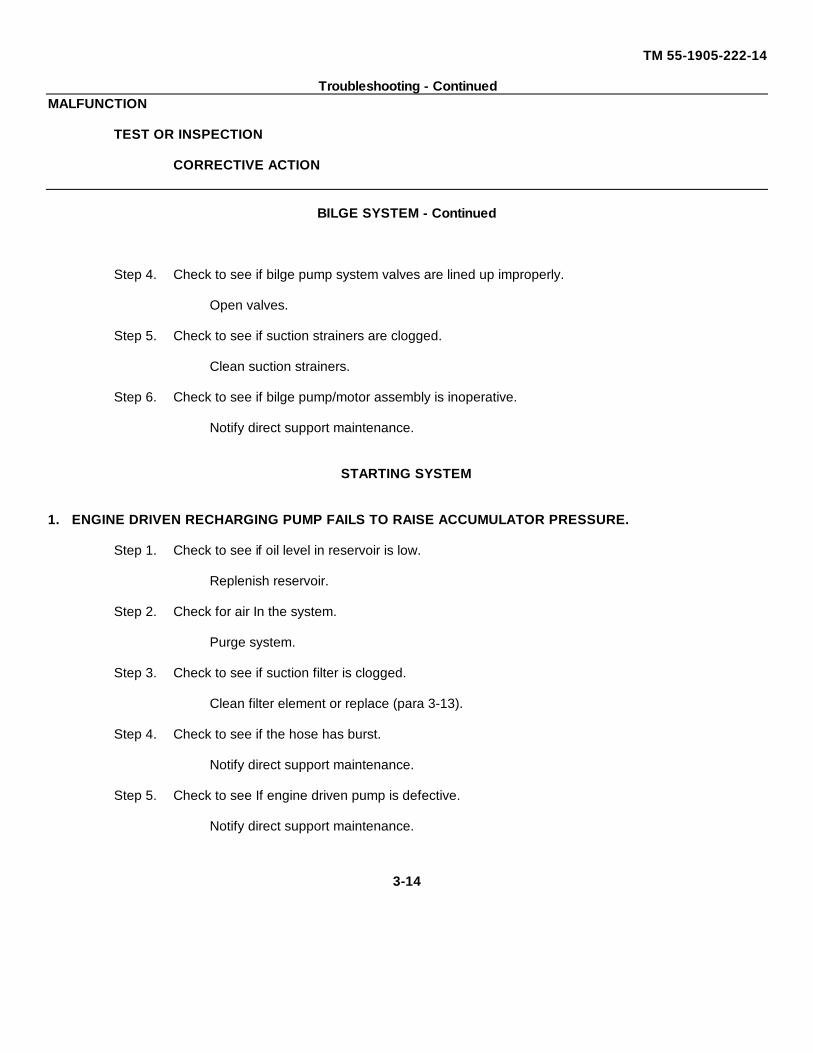
TM 55-1905-222-14
Troubleshooting - ContinuedMALFUNCTION
TEST OR INSPECTION
CORRECTIVE ACTION
BILGE SYSTEM - Continued
Step 4. Check to see if bilge pump system valves are lined up improperly.
Open valves.
Step 5. Check to see if suction strainers are clogged.
Clean suction strainers.
Step 6. Check to see if bilge pump/motor assembly is inoperative.
Notify direct support maintenance.
STARTING SYSTEM
1. ENGINE DRIVEN RECHARGING PUMP FAILS TO RAISE ACCUMULATOR PRESSURE.
Step 1. Check to see if oil level in reservoir is low.
Replenish reservoir.
Step 2. Check for air In the system.
Purge system.
Step 3. Check to see if suction filter is clogged.
Clean filter element or replace (para 3-13).
Step 4. Check to see if the hose has burst.
Notify direct support maintenance.
Step 5. Check to see If engine driven pump is defective.
Notify direct support maintenance.
3-14
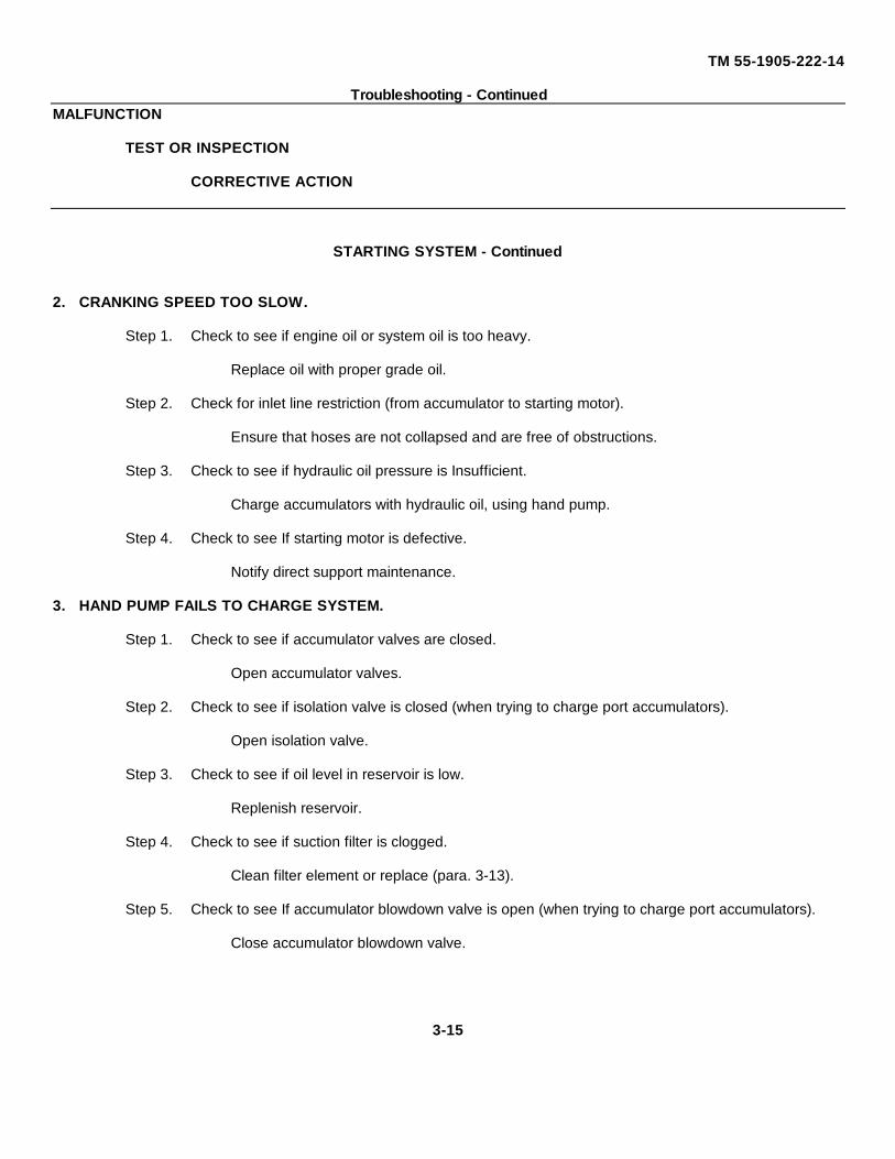
TM 55-1905-222-14
Troubleshooting - ContinuedMALFUNCTION
TEST OR INSPECTION
CORRECTIVE ACTION
STARTING SYSTEM - Continued
2. CRANKING SPEED TOO SLOW.
Step 1. Check to see if engine oil or system oil is too heavy.
Replace oil with proper grade oil.
Step 2. Check for inlet line restriction (from accumulator to starting motor).
Ensure that hoses are not collapsed and are free of obstructions.
Step 3. Check to see if hydraulic oil pressure is Insufficient.
Charge accumulators with hydraulic oil, using hand pump.
Step 4. Check to see If starting motor is defective.
Notify direct support maintenance.
3. HAND PUMP FAILS TO CHARGE SYSTEM.
Step 1. Check to see if accumulator valves are closed.
Open accumulator valves.
Step 2. Check to see if isolation valve is closed (when trying to charge port accumulators).
Open isolation valve.
Step 3. Check to see if oil level in reservoir is low.
Replenish reservoir.
Step 4. Check to see if suction filter is clogged.
Clean filter element or replace (para. 3-13).
Step 5. Check to see If accumulator blowdown valve is open (when trying to charge port accumulators).
Close accumulator blowdown valve.
3-15
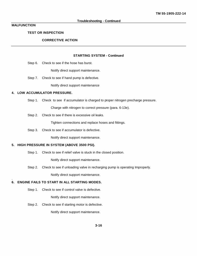
TM 55-1905-222-14
Troubleshooting - ContinuedMALFUNCTION
TEST OR INSPECTION
CORRECTIVE ACTION
STARTING SYSTEM - Continued
Step 6. Check to see if the hose has burst.
Notify direct support maintenance.
Step 7. Check to see if hand pump is defective.
Notify direct support maintenance
4. LOW ACCUMULATOR PRESSURE.
Step 1. Check to see if accumulator is charged to proper nitrogen precharge pressure.
Charge with nitrogen to correct pressure (para. 6-13e).
Step 2. Check to see if there is excessive oil leaks.
Tighten connections and replace hoses and fittings.
Step 3. Check to see if accumulator is defective.
Notify direct support maintenance.
5. HIGH PRESSURE IN SYSTEM (ABOVE 3500 PSI).
Step 1. Check to see if relief valve is stuck in the closed position.
Notify direct support maintenance.
Step 2. Check to see if unloading valve in recharging pump is operating Improperly.
Notify direct support maintenance..6. ENGINE FAILS TO START IN ALL STARTING MODES.
Step 1. Check to see if control valve is defective.
Notify direct support maintenance.
Step 2. Check to see if starting motor is defective.
Notify direct support maintenance.
3-16
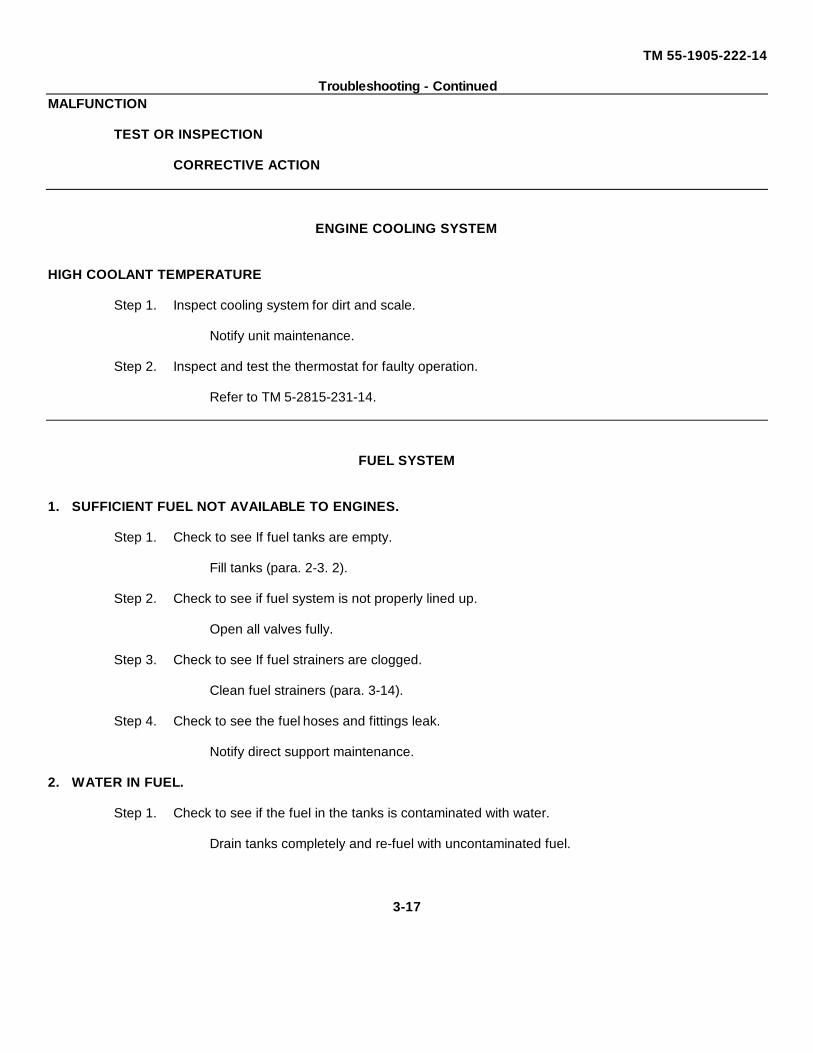
TM 55-1905-222-14
Troubleshooting - ContinuedMALFUNCTION
TEST OR INSPECTION
CORRECTIVE ACTION
ENGINE COOLING SYSTEM
HIGH COOLANT TEMPERATURE
Step 1. Inspect cooling system for dirt and scale.
Notify unit maintenance.
Step 2. Inspect and test the thermostat for faulty operation.
Refer to TM 5-2815-231-14.
FUEL SYSTEM
1. SUFFICIENT FUEL NOT AVAILABLE TO ENGINES.
Step 1. Check to see If fuel tanks are empty.
Fill tanks (para. 2-3. 2).
Step 2. Check to see if fuel system is not properly lined up.
Open all valves fully.
Step 3. Check to see If fuel strainers are clogged.
Clean fuel strainers (para. 3-14).
Step 4. Check to see the fuel hoses and fittings leak.
Notify direct support maintenance.
2. WATER IN FUEL.
Step 1. Check to see if the fuel in the tanks is contaminated with water.
Drain tanks completely and re-fuel with uncontaminated fuel.
3-17
TM 55-1905-222-14
Troubleshooting - ContinuedMALFUNCTION
TEST OR INSPECTION
CORRECTIVE ACTION
FUEL SYSTEM - Continued
Step 2. Check to see if leaky hoses are immersed in bilge water
Notify direct support maintenance
EXHAUST SYSTEM
1. EXHAUST SYSTEM TOO NOISY
Check to see if mufflers are defective.
Notify unit maintenance.
2. EXHAUST SYSTEM TOO HOT.
Check to see If there is leakage of exhaust gas or cooling water in the exhaust system.
Notify unit maintenance.
PROPELLER, PROPELLER SHAFT AND STUFFING BOX
1. EXCESSIVE LEAKAGE FROM STUFFING BOX.
Check for loose or worn packing.
Adjust or replace packing (para. 6-25.
2. EXCESSIVELY HOT STUFFING BOX.
Check to see if packing gland is too tight.
Adjust packing (para 6-25).
3-18
TM 55-1905-222-14
Troubleshooting - ContinuedMALFUNCTION
TEST OR INSPECTION
CORRECTIVE ACTION
PROPELLER, PROPELLER SHAFT AND STUFFING BOX - Continued
3. EXCESSIVE VIBRATION IN PROPELLER SHAFT
Step 1. Check for misalignment of propeller coupling.
Notify general support maintenance.
Step 2. Check for bent or broken propeller.
Notify general support maintenance.
3-19
TM 55-1905-222-14
Section III. MAINTENANCE PROCEDURES
3-3 GENERAL MAINTENANCE PROCEDURES.
This section contains maintenance procedures that are the responsibility of the operator, as authorized by theMaintenance Allocation Chart (MAC). Refer to the operator PMCS for all INSPECT and SERVICE maintenancefunctions on the MAC that are not addressed in the following maintenance procedures.
NOTE
Due to the mission and crew capabilities of thevessel, maintenance normally assigned toorganizational level or higher may be assigned tooperator crew.
MAINTENANCE OF NAVIGATION LIGHTS
3-4 REPLACE NAVIGATION LIGHT BULB AND LENS HOUSING.
This task covers a. Removalb. Installation
INITIAL SETUP
Tools: Equipment Conditions:
Tool Kit, Mechanic's, Rail Navigation Lights off.and Marine5180-00-629-9783
Materials/Parts General Safety Instructions
Bulb Energized electrical equipment isP/N 904-00003 dangerous Never work on energized
Bulb equipment unless authorized to do soP/N 904-00006 by responsible authority
Lens HousingP/N 33506
Lens HousingP/N 33501, 33502, 33504, 33505
Locking RingP/N 8-3514-011
3-20
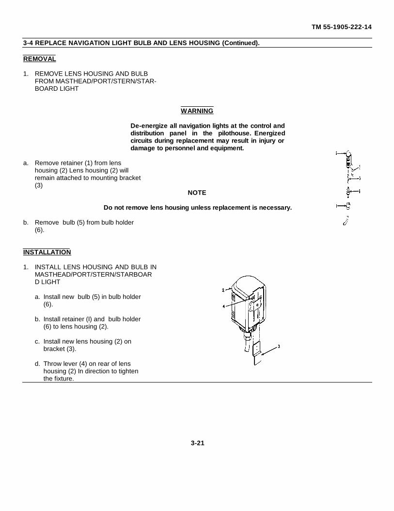
TM 55-1905-222-14
3-4 REPLACE NAVIGATION LIGHT BULB AND LENS HOUSING (Continued).
REMOVAL
1. REMOVE LENS HOUSING AND BULBFROM MASTHEAD/PORT/STERN/STAR-BOARD LIGHT
WARNING
De-energize all navigation lights at the control anddistribution panel in the pilothouse. Energizedcircuits during replacement may result in injury ordamage to personnel and equipment.
a. Remove retainer (1) from lenshousing (2) Lens housing (2) willremain attached to mounting bracket(3)
NOTE
Do not remove lens housing unless replacement is necessary.
b. Remove bulb (5) from bulb holder(6).
INSTALLATION
1. INSTALL LENS HOUSING AND BULB INMASTHEAD/PORT/STERN/STARBOARD LIGHT
a. Install new bulb (5) in bulb holder(6).
b. Install retainer (I) and bulb holder(6) to lens housing (2).
c. Install new lens housing (2) onbracket (3).
d. Throw lever (4) on rear of lenshousing (2) In direction to tightenthe fixture.
3-21
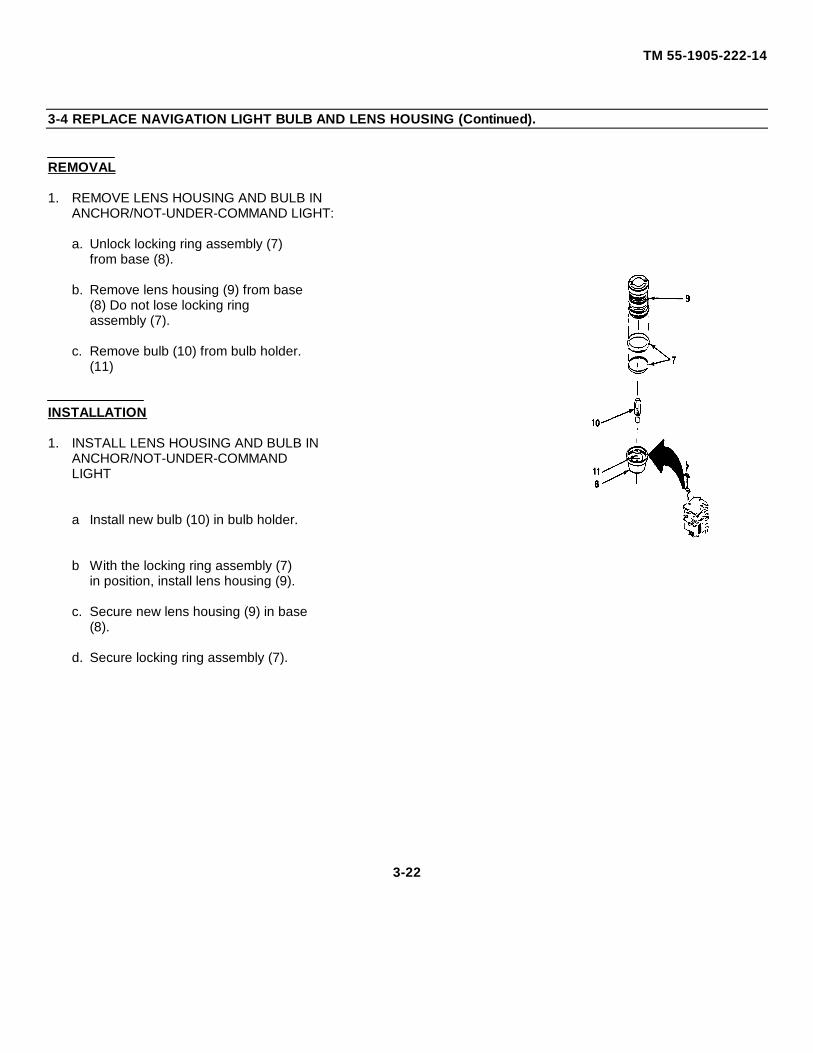
TM 55-1905-222-14
3-4 REPLACE NAVIGATION LIGHT BULB AND LENS HOUSING (Continued).
REMOVAL
1. REMOVE LENS HOUSING AND BULB INANCHOR/NOT-UNDER-COMMAND LIGHT:
a. Unlock locking ring assembly (7)from base (8).
b. Remove lens housing (9) from base(8) Do not lose locking ringassembly (7).
c. Remove bulb (10) from bulb holder.(11)
INSTALLATION
1. INSTALL LENS HOUSING AND BULB INANCHOR/NOT-UNDER-COMMANDLIGHT
a Install new bulb (10) in bulb holder.
b With the locking ring assembly (7)in position, install lens housing (9).
c. Secure new lens housing (9) in base(8).
d. Secure locking ring assembly (7).
3-22
TM 55-1905-222-14
MAINTENANCE OF ALTERNATOR3-5 FUNCTIONALI TEST OF ALTERNA'TOR
INITIAL SETUP
Tools: General Safety Instructions:Tool Kit, Mechanic's, Rall
and Marine Do NOT under any circumstances, short FIELD5 180-00-629-9783 terminal of alternator to ground.
Multimeter (TS-352B/U or equiv)6625-00-553-0142 Do NOT disconnect voltage regulator while alter-
Multimeter Jumper leads 2, 4, 6, and 10 nator Is operating.feet in length with alligator clips
Tester, Battery Do NOT disconnect alternator output lead from6630-00-171-5126 alternator while the alternator is operating
Equipment Conditions Do NOT remove alternator without first discon-necting the negative battery cable from the bat-
Refer to NOTES in procedure. tery.
NOTE
o Before actual in-vessel testing begins, check the battery to be sure it is fully charged (Normal 1.260 -1.285 Sp. Gr.), if not, charge the battery first.
o Check that wires and cables are free of corrosion.
o The alternator drive belt must be properly adjusted, in good condition, and free of grease or oils thatmay induce slipping under load.
1. SETUP MULTIMETER
a. Hold multimeter in hand. Switch to 0-40volts dc range
b. Connect negative multimeter lead to nega-tive battery terminal.
2. BATTERY VOLTAGE AND SHORTEDPOSITIVE DIODE TEST
NOTE
The engine should not be running when performing this test.
Change 2 3-23
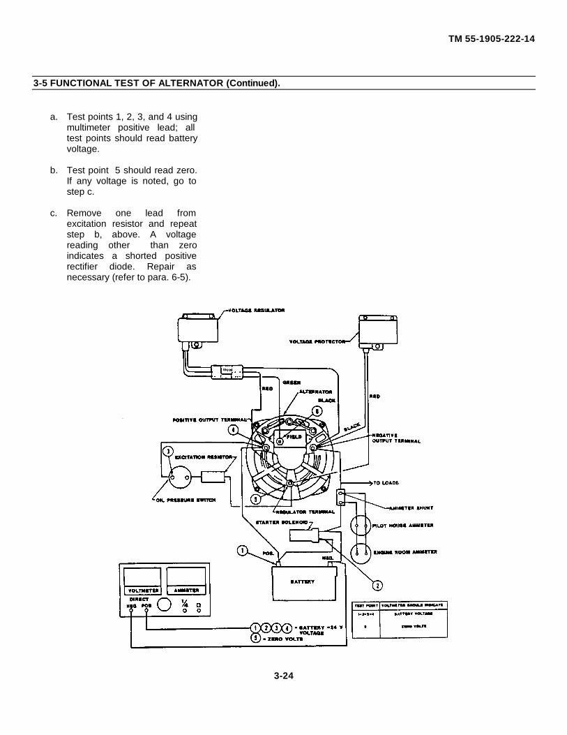
TM 55-1905-222-14
3-5 FUNCTIONAL TEST OF ALTERNATOR (Continued).
a. Test points 1, 2, 3, and 4 usingmultimeter positive lead; alltest points should read batteryvoltage.
b. Test point 5 should read zero.If any voltage is noted, go tostep c.
c. Remove one lead fromexcitation resistor and repeatstep b, above. A voltagereading other than zeroindicates a shorted positiverectifier diode. Repair asnecessary (refer to para. 6-5).
3-24
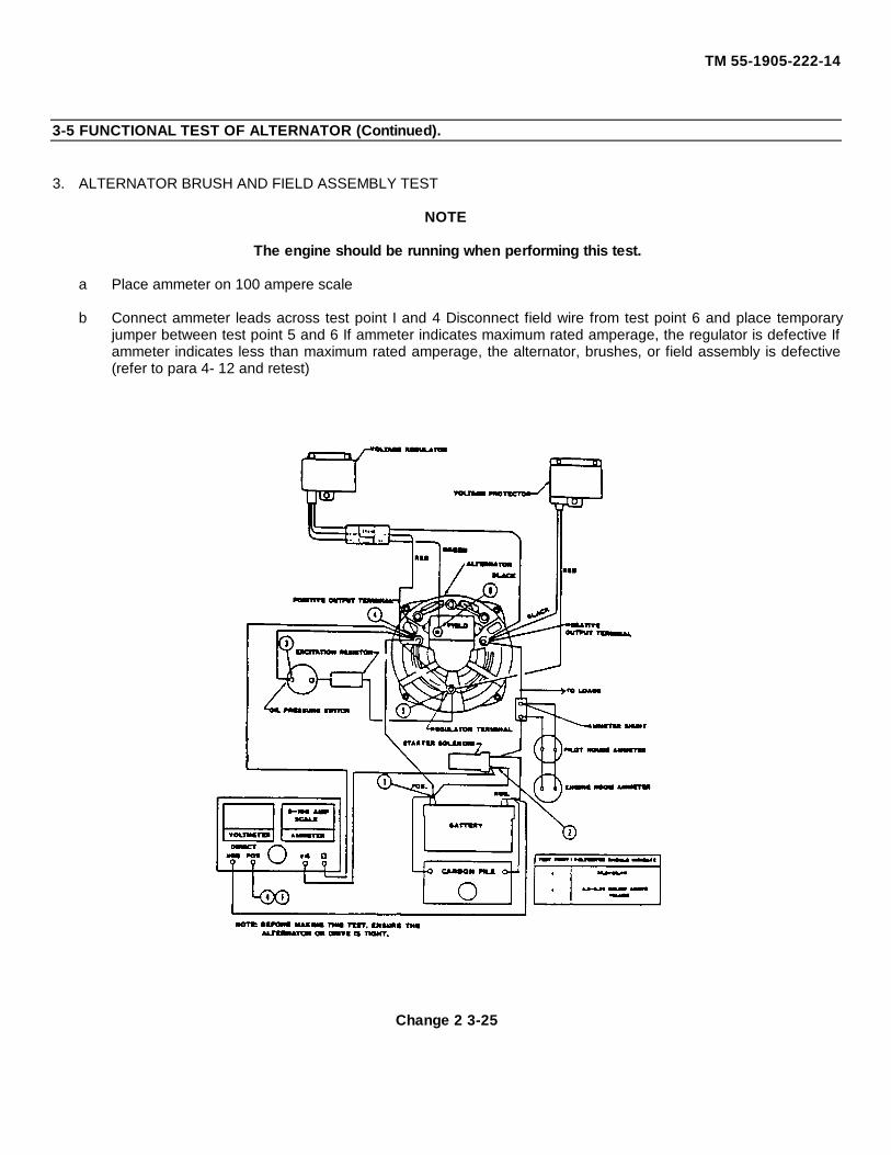
TM 55-1905-222-14
3-5 FUNCTIONAL TEST OF ALTERNATOR (Continued).
3. ALTERNATOR BRUSH AND FIELD ASSEMBLY TEST
NOTE
The engine should be running when performing this test.
a Place ammeter on 100 ampere scale
b Connect ammeter leads across test point I and 4 Disconnect field wire from test point 6 and place temporaryjumper between test point 5 and 6 If ammeter indicates maximum rated amperage, the regulator is defective Ifammeter indicates less than maximum rated amperage, the alternator, brushes, or field assembly is defective(refer to para 4- 12 and retest)
Change 2 3-25

TM 55-1905-222-14
3-5 FUNCTIONAL TEST OF ALTERNATOR (Continued).
4. ALTERNATOR OUTPUT TEST. This paragraph is deleted
3-26 Change 2
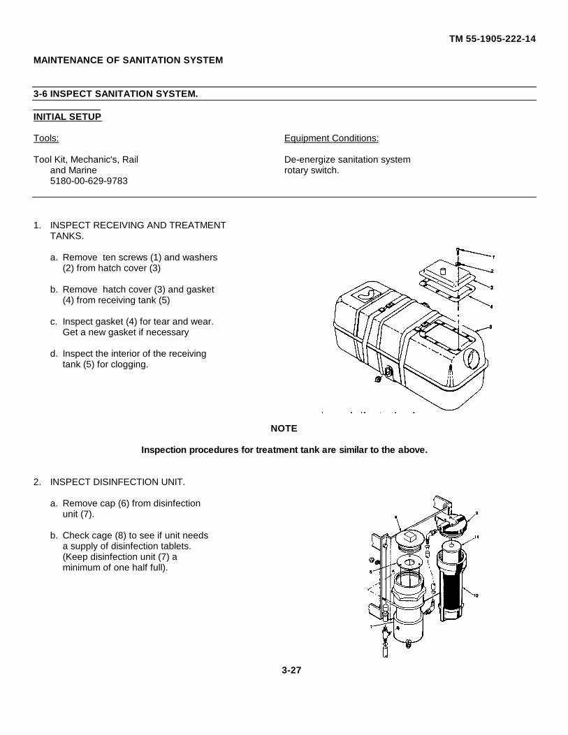
TM 55-1905-222-14
MAINTENANCE OF SANITATION SYSTEM
3-6 INSPECT SANITATION SYSTEM.
INITIAL SETUP
Tools: Equipment Conditions:
Tool Kit, Mechanic's, Rail De-energize sanitation systemand Marine rotary switch.5180-00-629-9783
1. INSPECT RECEIVING AND TREATMENTTANKS.
a. Remove ten screws (1) and washers(2) from hatch cover (3)
b. Remove hatch cover (3) and gasket(4) from receiving tank (5)
c. Inspect gasket (4) for tear and wear.Get a new gasket if necessary
d. Inspect the interior of the receivingtank (5) for clogging.
NOTE
Inspection procedures for treatment tank are similar to the above.
2. INSPECT DISINFECTION UNIT.
a. Remove cap (6) from disinfectionunit (7).
b. Check cage (8) to see if unit needsa supply of disinfection tablets.(Keep disinfection unit (7) aminimum of one half full).
3-27
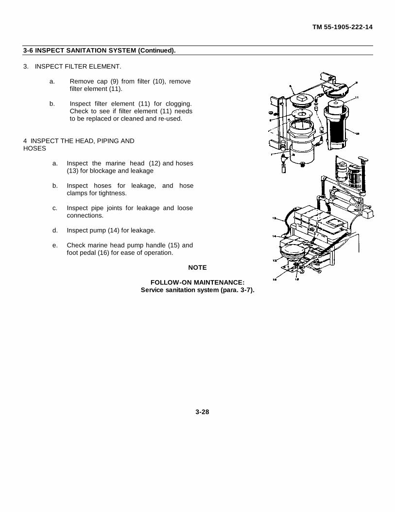
TM 55-1905-222-14
3-6 INSPECT SANITATION SYSTEM (Continued).
3. INSPECT FILTER ELEMENT.
a. Remove cap (9) from filter (10), removefilter element (11).
b. Inspect filter element (11) for clogging.Check to see if filter element (11) needsto be replaced or cleaned and re-used.
4 INSPECT THE HEAD, PIPING ANDHOSES
a. Inspect the marine head (12) and hoses(13) for blockage and leakage
b. Inspect hoses for leakage, and hoseclamps for tightness.
c. Inspect pipe joints for leakage and looseconnections.
d. Inspect pump (14) for leakage.
e. Check marine head pump handle (15) andfoot pedal (16) for ease of operation.
NOTE
FOLLOW-ON MAINTENANCE:Service sanitation system (para. 3-7).
3-28
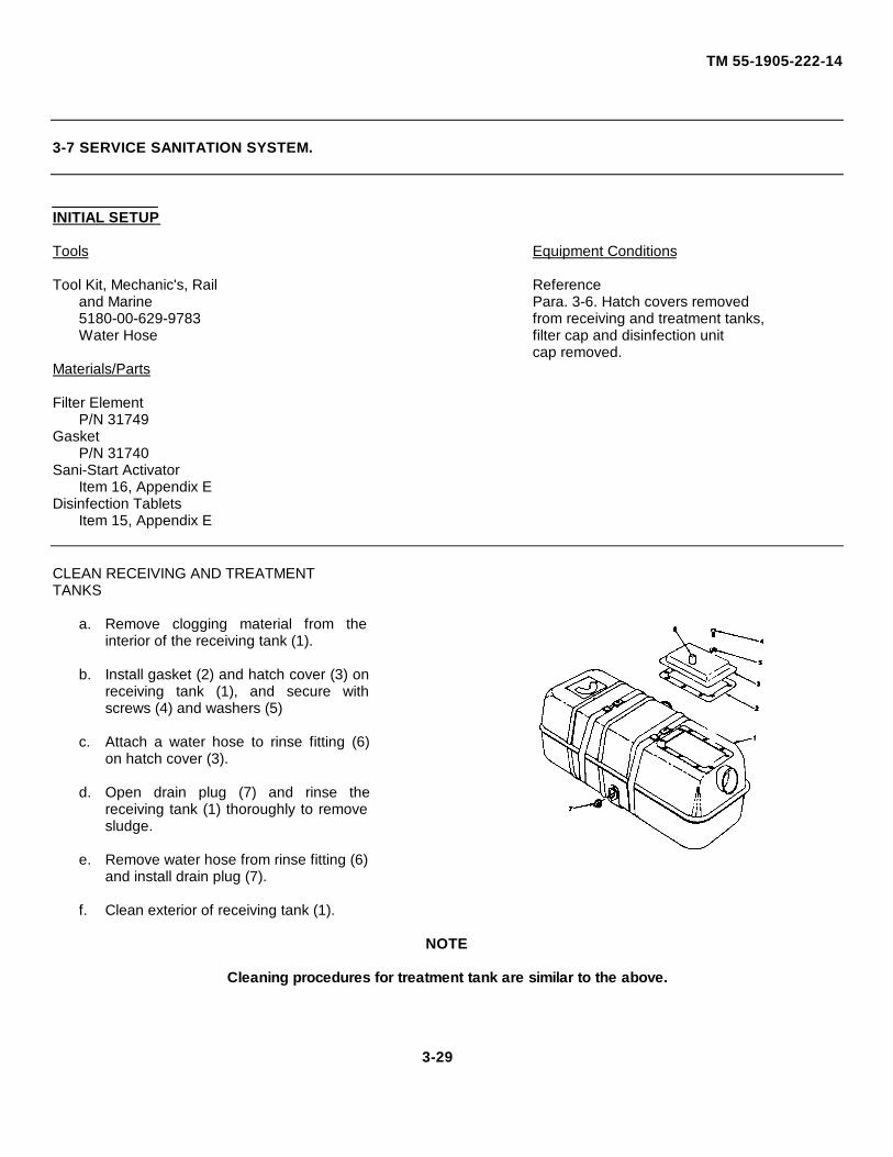
TM 55-1905-222-14
3-7 SERVICE SANITATION SYSTEM.
INITIAL SETUP
Tools Equipment Conditions
Tool Kit, Mechanic's, Rail Referenceand Marine Para. 3-6. Hatch covers removed5180-00-629-9783 from receiving and treatment tanks,Water Hose filter cap and disinfection unit
cap removed.Materials/Parts
Filter ElementP/N 31749
GasketP/N 31740
Sani-Start ActivatorItem 16, Appendix E
Disinfection TabletsItem 15, Appendix E
CLEAN RECEIVING AND TREATMENTTANKS
a. Remove clogging material from theinterior of the receiving tank (1).
b. Install gasket (2) and hatch cover (3) onreceiving tank (1), and secure withscrews (4) and washers (5)
c. Attach a water hose to rinse fitting (6)on hatch cover (3).
d. Open drain plug (7) and rinse thereceiving tank (1) thoroughly to removesludge.
e. Remove water hose from rinse fitting (6)and install drain plug (7).
f. Clean exterior of receiving tank (1).
NOTE
Cleaning procedures for treatment tank are similar to the above.
3-29
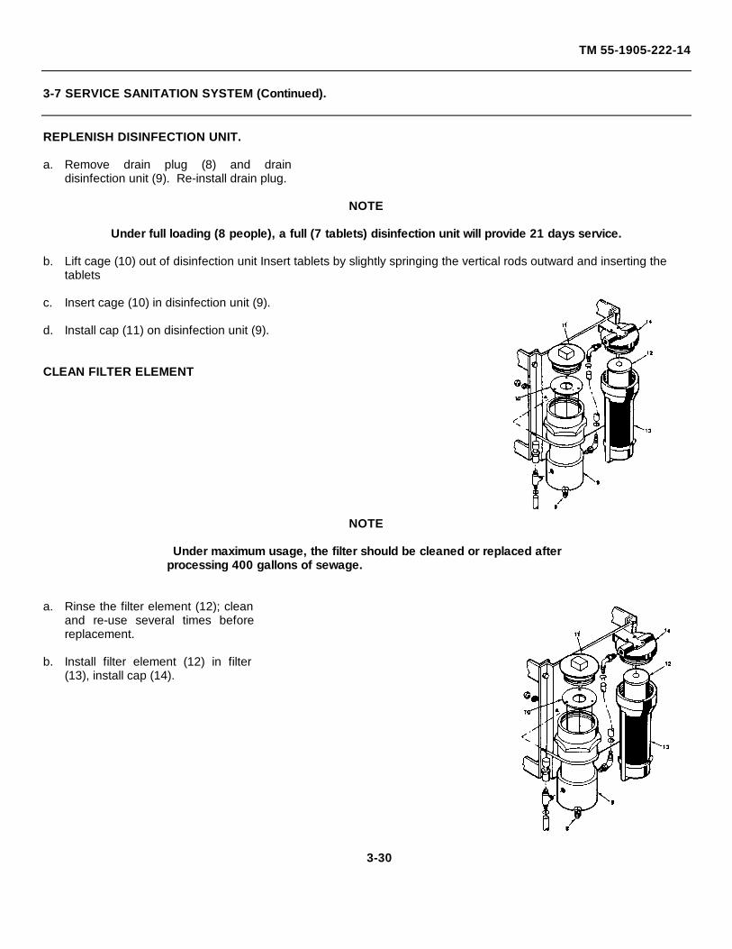
TM 55-1905-222-14
3-7 SERVICE SANITATION SYSTEM (Continued).
REPLENISH DISINFECTION UNIT.
a. Remove drain plug (8) and draindisinfection unit (9). Re-install drain plug.
NOTE
Under full loading (8 people), a full (7 tablets) disinfection unit will provide 21 days service.
b. Lift cage (10) out of disinfection unit Insert tablets by slightly springing the vertical rods outward and inserting thetablets
c. Insert cage (10) in disinfection unit (9).
d. Install cap (11) on disinfection unit (9).
CLEAN FILTER ELEMENT
NOTE
Under maximum usage, the filter should be cleaned or replaced afterprocessing 400 gallons of sewage.
a. Rinse the filter element (12); cleanand re-use several times beforereplacement.
b. Install filter element (12) in filter(13), install cap (14).
3-30
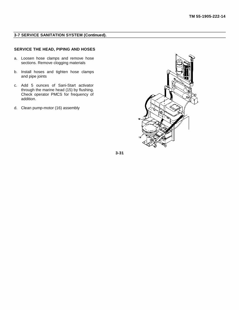
TM 55-1905-222-14
3-7 SERVICE SANITATION SYSTEM (Continued).
SERVICE THE HEAD, PIPING AND HOSES
a. Loosen hose clamps and remove hosesections. Remove clogging materials
b. Install hoses and tighten hose clampsand pipe joints
c. Add 5 ounces of Sani-Start activatorthrough the marine head (15) by flushing.Check operator PMCS for frequency ofaddition.
d. Clean pump-motor (16) assembly
3-31

TM 55-1905-222-14
MAINTENANCE OF RAMP SYSTEM
3-8 INSPECT RAMP SYSTEM RESERVOIR, STRAINERS AND FILTERS.
INITIAL SETUP
Tools. General Safety Instructions:
Tool Kit, Mechanic's, Rail Observe warning stenciled onand Marine Ramp/Starting System reservoir5180-00-629-9783
Equipment Conditions:
Engine running, ramppump In operation.
1. INSPECT FILTER INDICATOR
a. With ramp pump in operation, check rampreturn filter indicator (I) The maximumallowable pressure drop across the filters is 15psi (Excessive pressure drop across the filterscould indicate dirty oil condition)
b. Shut down LCM-8 prior to inspection ofreservoir and strainers
2. INSPECT RESERVOIR AND STRAINERS
WARNING
The engine should not be running when performing thisinspection. Injury to personnel may result.
a. Visually inspect the exterior of the reservoir (2)for leaks.
b. Clean tank top with a clean lint-free cloth
c. With the engine and all systems shut down,remove thirty-two capscrews (3), remove tankinspection cover (4) and gasket (5). Inspectgasket (5) for breaks or any defects Get a newgasket If necessary
3-32
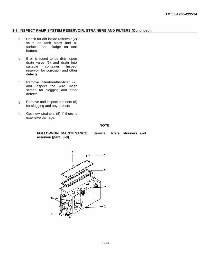
TM 55-1905-222-14
3-8 INSPECT RAMP SYSTEM RESERVOIR, STRAINERS AND FILTERS (Continued).
d. Check for dirt inside reservoir (2)scum on tank sides and oilsurface, and sludge on tankbottom.
e. If oil is found to be dirty, opendrain valve (6) and drain intosuitable container Inspectreservoir for corrosion and otherdefects.
f. Remove filler/breather-filter (7)and Inspect the wire meshscreen for clogging and otherdefects.
g. Remove and inspect strainers (8)for clogging and any defects
h. Get new strainers (8) if there isextensive damage.
NOTE
FOLLOW-ON MAINTENANCE: Service filters, strainers andreservoir (para. 3-9).
3-33
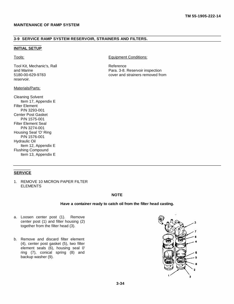
TM 55-1905-222-14
MAINTENANCE OF RAMP SYSTEM
3-9 SERVICE RAMP SYSTEM RESERVOIR, STRAINERS AND FILTERS.
INITIAL SETUP
Tools: Equipment Conditions:
Tool Kit, Mechanic's, Rall Referenceand Marine Para. 3-8. Reservoir inspection5180-00-629-9783 cover and strainers removed fromreservoir.
Materials/Parts:
Cleaning SolventItem 17, Appendix E
Filter ElementP/N 3293-001
Center Post GasketP/N 1575-001
Filter Element SealP/N 3274-001
Housing Seal 'O' RingP/N 1576-001
Hydraulic OilItem 12, Appendix E
Flushing CompoundItem 13, Appendix E
SERVICE
1. REMOVE 10 MICRON PAPER FILTERELEMENTS
NOTE
Have a container ready to catch oil from the filter head casting.
a. Loosen center post (1). Removecenter post (1) and filter housing (2)together from the filter head (3).
b. Remove and discard filter element(4), center post gasket (5), two filterelement seals (6), housing seal 0'ring (7), conical spring (8) andbackup washer (9).
3-34
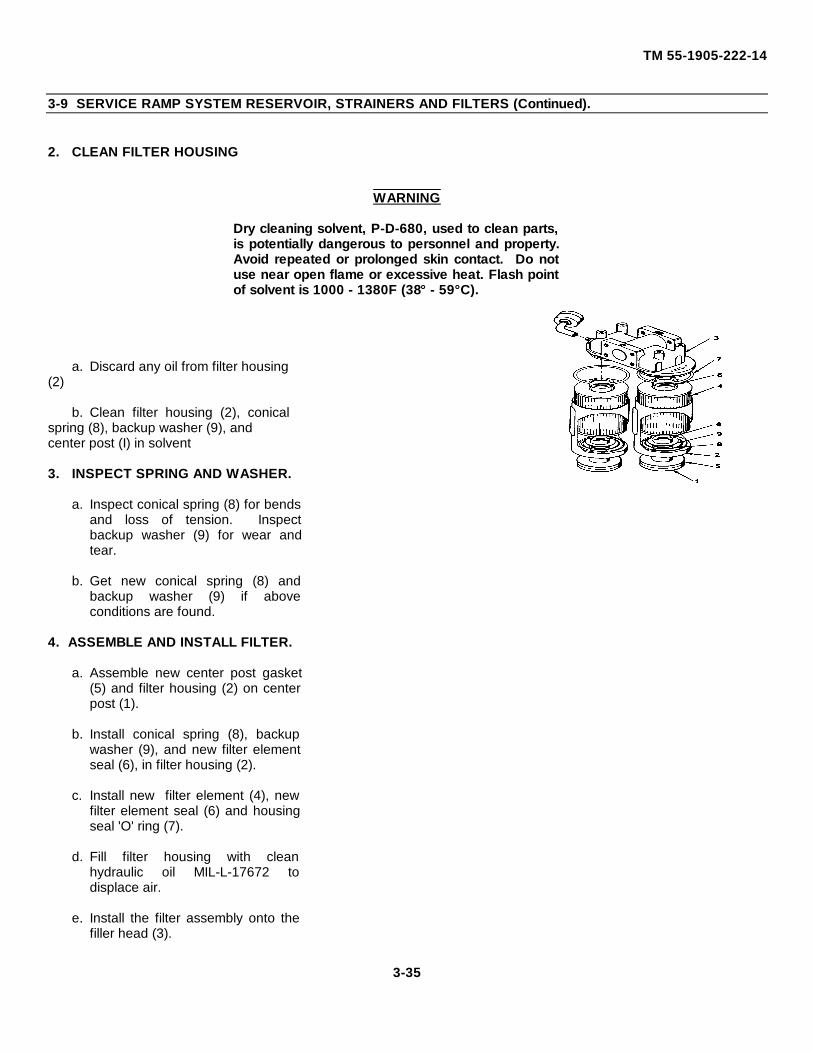
TM 55-1905-222-14
3-9 SERVICE RAMP SYSTEM RESERVOIR, STRAINERS AND FILTERS (Continued).
2. CLEAN FILTER HOUSING
WARNING
Dry cleaning solvent, P-D-680, used to clean parts,is potentially dangerous to personnel and property.Avoid repeated or prolonged skin contact. Do notuse near open flame or excessive heat. Flash pointof solvent is 1000 - 1380F (38° - 59°C).
a. Discard any oil from filter housing(2)
b. Clean filter housing (2), conicalspring (8), backup washer (9), andcenter post (I) in solvent
3. INSPECT SPRING AND WASHER.
a. Inspect conical spring (8) for bendsand loss of tension. Inspectbackup washer (9) for wear andtear.
b. Get new conical spring (8) andbackup washer (9) if aboveconditions are found.
4. ASSEMBLE AND INSTALL FILTER.
a. Assemble new center post gasket(5) and filter housing (2) on centerpost (1).
b. Install conical spring (8), backupwasher (9), and new filter elementseal (6), in filter housing (2).
c. Install new filter element (4), newfilter element seal (6) and housingseal 'O' ring (7).
d. Fill filter housing with cleanhydraulic oil MIL-L-17672 todisplace air.
e. Install the filter assembly onto thefiller head (3).
3-35
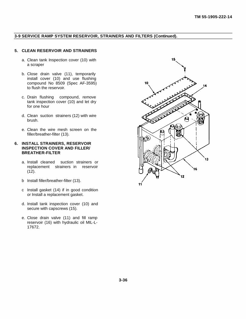
TM 55-1905-222-14
3-9 SERVICE RAMP SYSTEM RESERVOIR, STRAINERS AND FILTERS (Continued).
5. CLEAN RESERVOIR AND STRAINERS
a. Clean tank Inspection cover (10) witha scraper
b. Close drain valve (11), temporarilyinstall cover (10) and use flushingcompound No 8509 (Spec AF-3595)to flush the reservoir.
c. Drain flushing compound, removetank inspection cover (10) and let dryfor one hour
d. Clean suction strainers (12) with wirebrush.
e. Clean the wire mesh screen on thefiller/breather-filter (13).
6. INSTALL STRAINERS, RESERVOIRINSPECTION COVER AND FILLER/BREATHER-FILTER
a. Install cleaned suction strainers orreplacement strainers in reservoir(12).
b Install filler/breather-filter (13).
c Install gasket (14) if in good conditionor Install a replacement gasket.
d. Install tank inspection cover (10) andsecure with capscrews (15).
e. Close drain valve (11) and fill rampreservoir (16) with hydraulic oil MIL-L-17672.
3-36
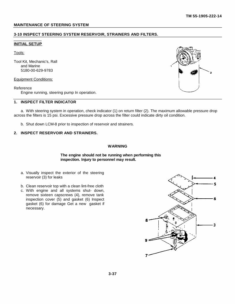
TM 55-1905-222-14
MAINTENANCE OF STEERING SYSTEM
3-10 INSPECT STEERING SYSTEM RESERVOIR, STRAINERS AND FILTERS.
INITIAL SETUP
Tools:
Tool Kit, Mechanic's, Ralland Marine5180-00-629-9783
Equipment Conditions:
ReferenceEngine running, steering pump In operation.
1. INSPECT FILTER INDICATOR
a. With steering system in operation, check indicator (1) on return filter (2). The maximum allowable pressure dropacross the filters is 15 psi. Excessive pressure drop across the filter could indicate dirty oil condition.
b. Shut down LCM-8 prior to inspection of reservoir and strainers.
2. INSPECT RESERVOIR AND STRAINERS.
WARNING
The engine should not be running when performing thisinspection. Injury to personnel may result.
a. Visually inspect the exterior of the steeringreservoir (3) for leaks
b. Clean reservoir top with a clean lint-free clothc. With engine and all systems shut- down,
remove sixteen capscrews (4), remove tankinspection cover (5) and gasket (6) Inspectgasket (6) for damage Get a new gasket ifnecessary.
3-37
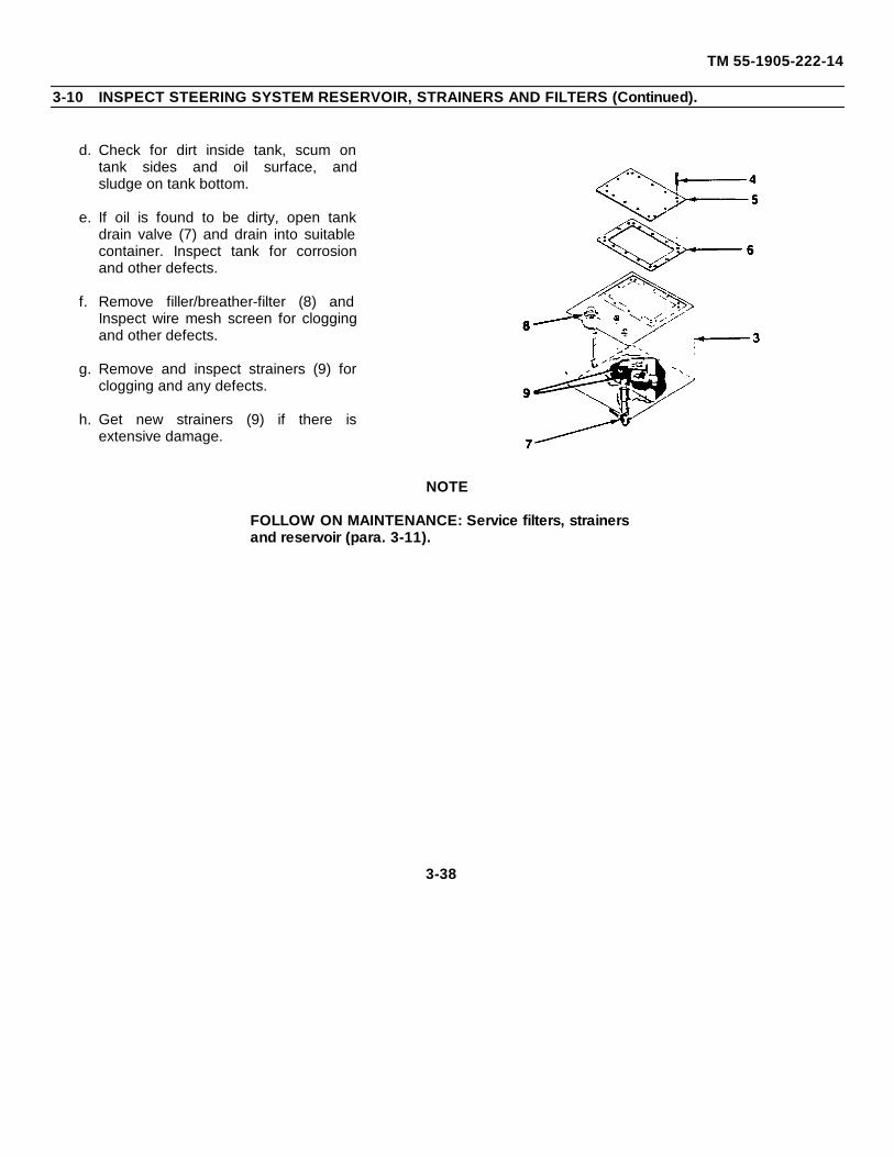
TM 55-1905-222-14
3-10 INSPECT STEERING SYSTEM RESERVOIR, STRAINERS AND FILTERS (Continued).
d. Check for dirt inside tank, scum ontank sides and oil surface, andsludge on tank bottom.
e. If oil is found to be dirty, open tankdrain valve (7) and drain into suitablecontainer. Inspect tank for corrosionand other defects.
f. Remove filler/breather-filter (8) andInspect wire mesh screen for cloggingand other defects.
g. Remove and inspect strainers (9) forclogging and any defects.
h. Get new strainers (9) if there isextensive damage.
NOTE
FOLLOW ON MAINTENANCE: Service filters, strainersand reservoir (para. 3-11).
3-38
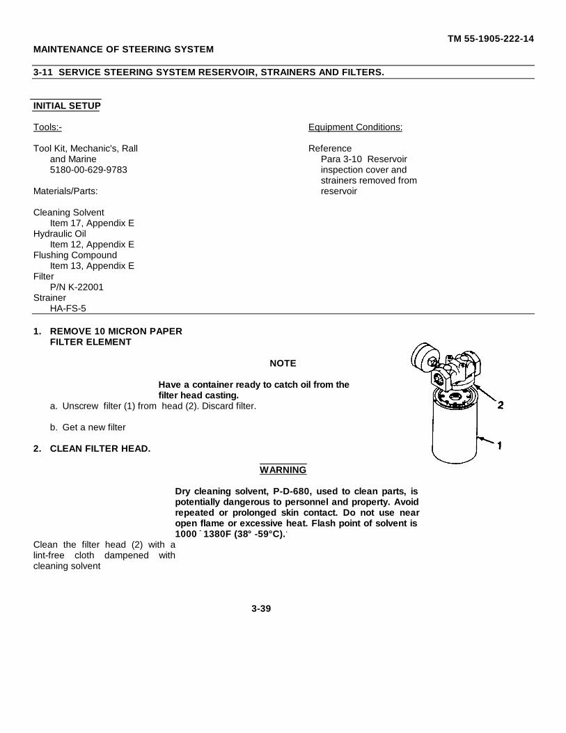
TM 55-1905-222-14MAINTENANCE OF STEERING SYSTEM
3-11 SERVICE STEERING SYSTEM RESERVOIR, STRAINERS AND FILTERS.
INITIAL SETUP
Tools:- Equipment Conditions:
Tool Kit, Mechanic's, Rall Referenceand Marine Para 3-10 Reservoir5180-00-629-9783 inspection cover and
strainers removed fromMaterials/Parts: reservoir
Cleaning SolventItem 17, Appendix E
Hydraulic OilItem 12, Appendix E
Flushing CompoundItem 13, Appendix E
FilterP/N K-22001
StrainerHA-FS-5
1. REMOVE 10 MICRON PAPERFILTER ELEMENT
NOTE
Have a container ready to catch oil from thefilter head casting.
a. Unscrew filter (1) from head (2). Discard filter.
b. Get a new filter
2. CLEAN FILTER HEAD.
WARNING
Dry cleaning solvent, P-D-680, used to clean parts, ispotentially dangerous to personnel and property. Avoidrepeated or prolonged skin contact. Do not use nearopen flame or excessive heat. Flash point of solvent is1000 - 1380F (38° -59°C)..
Clean the filter head (2) with alint-free cloth dampened withcleaning solvent
3-39
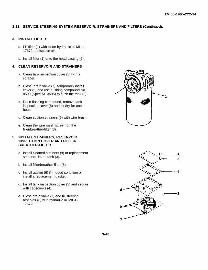
TM 55-1905-222-14
3-11 SERVICE STEERING SYSTEM RESERVOIR, STRAINERS AND FILTERS (Continued).
3. INSTALL FILTER
a. Fill filter (1) with clean hydraulic oil MIL-L-17672 to displace air.
b. Install filter (1) onto the head casting (2).
4. CLEAN RESERVOIR AND STRAINERS
a. Clean tank inspection cover (5) with ascraper.
b. Close drain valve (7), temporarily installcover (5) and use flushing compound No8509 (Spec AF-3595) to flush the tank (3)
c. Drain flushing compound, remove tankinspection cover (5) and let dry for onehour.
d. Clean suction strainers (9) with wire brush.
e. Clean the wire mesh screen on thefiller/breather-filter (8).
5. INSTALL STRAINERS, RESERVOIRINSPECTION COVER AND FILLER/BREATHER-FILTER.
a. Install cleaned strainers (9) or replacementstrainers in the tank (3).
b Install filler/breather-filter (8).
c Install gasket (6) if in good condition orinstall a replacement gasket.
d. Install tank inspection cover (5) and securewith capscrews (4).
e. Close drain valve (7) and fill steeringreservoir (3) with hydraulic oil MIL-L-17672.
3-40
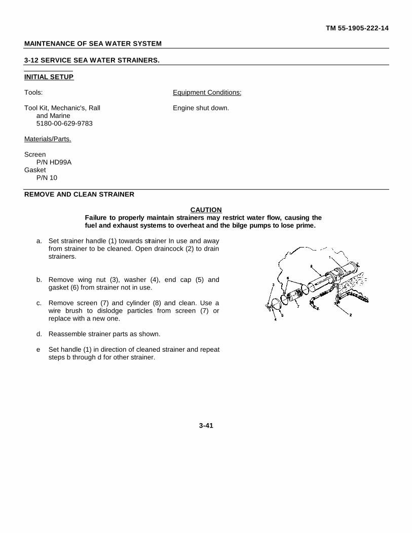
TM 55-1905-222-14
MAINTENANCE OF SEA WATER SYSTEM
3-12 SERVICE SEA WATER STRAINERS.
INITIAL SETUP
Tools: Equipment Conditions:
Tool Kit, Mechanic's, Rall Engine shut down.and Marine5180-00-629-9783
Materials/Parts.
ScreenP/N HD99A
GasketP/N 10
REMOVE AND CLEAN STRAINER
CAUTIONFailure to properly maintain strainers may restrict water flow, causing thefuel and exhaust systems to overheat and the bilge pumps to lose prime.
a. Set strainer handle (1) towards strainer In use and awayfrom strainer to be cleaned. Open draincock (2) to drainstrainers.
b. Remove wing nut (3), washer (4), end cap (5) andgasket (6) from strainer not in use.
c. Remove screen (7) and cylinder (8) and clean. Use awire brush to dislodge particles from screen (7) orreplace with a new one.
d. Reassemble strainer parts as shown.
e Set handle (1) in direction of cleaned strainer and repeatsteps b through d for other strainer.
3-41
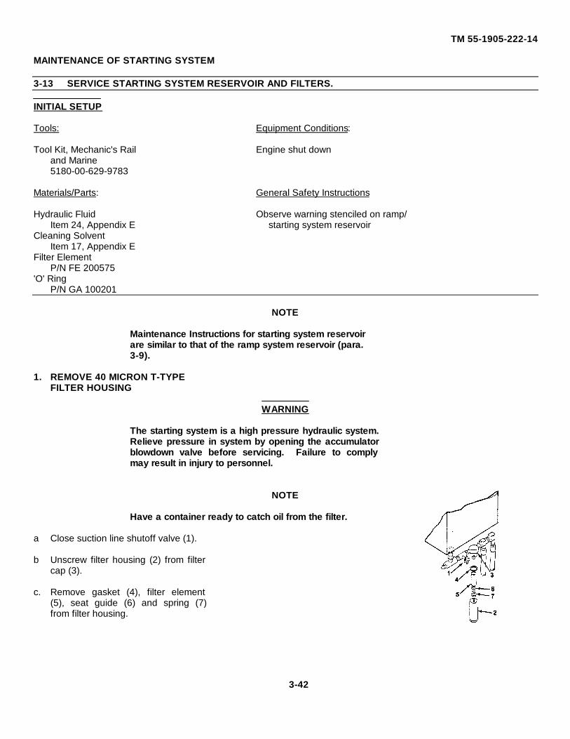
TM 55-1905-222-14
MAINTENANCE OF STARTING SYSTEM
3-13 SERVICE STARTING SYSTEM RESERVOIR AND FILTERS.
INITIAL SETUP
Tools: Equipment Conditions:
Tool Kit, Mechanic's Rail Engine shut downand Marine5180-00-629-9783
Materials/Parts: General Safety Instructions
Hydraulic Fluid Observe warning stenciled on ramp/Item 24, Appendix E starting system reservoir
Cleaning SolventItem 17, Appendix E
Filter ElementP/N FE 200575
'O' RingP/N GA 100201
NOTE
Maintenance Instructions for starting system reservoirare similar to that of the ramp system reservoir (para.3-9).
1. REMOVE 40 MICRON T-TYPEFILTER HOUSING
WARNING
The starting system is a high pressure hydraulic system.Relieve pressure in system by opening the accumulatorblowdown valve before servicing. Failure to complymay result in injury to personnel.
NOTE
Have a container ready to catch oil from the filter.
a Close suction line shutoff valve (1).
b Unscrew filter housing (2) from filtercap (3).
c. Remove gasket (4), filter element(5), seat guide (6) and spring (7)from filter housing.
3-42
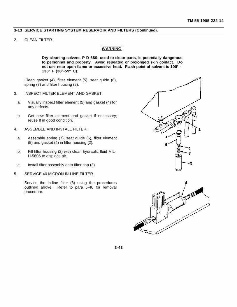
TM 55-1905-222-14
3-13 SERVICE STARTING SYSTEM RESERVOIR AND FILTERS (Continued).
2. CLEAN FILTER
WARNING
Dry cleaning solvent, P-D-680, used to clean parts, is potentially dangerousto personnel and property. Avoid repeated or prolonged skin contact. Donot use near open flame or excessive heat. Flash point of solvent is 100°-138°F (38°-59°C).
Clean gasket (4), filter element (5), seat guide (6),spring (7) and filter housing (2).
3. INSPECT FILTER ELEMENT AND GASKET.
a. Visually inspect filter element (5) and gasket (4) forany defects.
b. Get new filter element and gasket if necessary;reuse If in good condition.
4. ASSEMBLE AND INSTALL FILTER.
a. Assemble spring (7), seat guide (6), filter element(5) and gasket (4) in filter housing (2).
b. Fill filter housing (2) with clean hydraulic fluid MIL-H-5606 to displace air.
c. Install filter assembly onto filter cap (3).
5. SERVICE 40 MICRON IN-LINE FILTER.
Service the in-line filter (8) using the proceduresoutlined above. Refer to para 5-46 for removalprocedure.
3-43
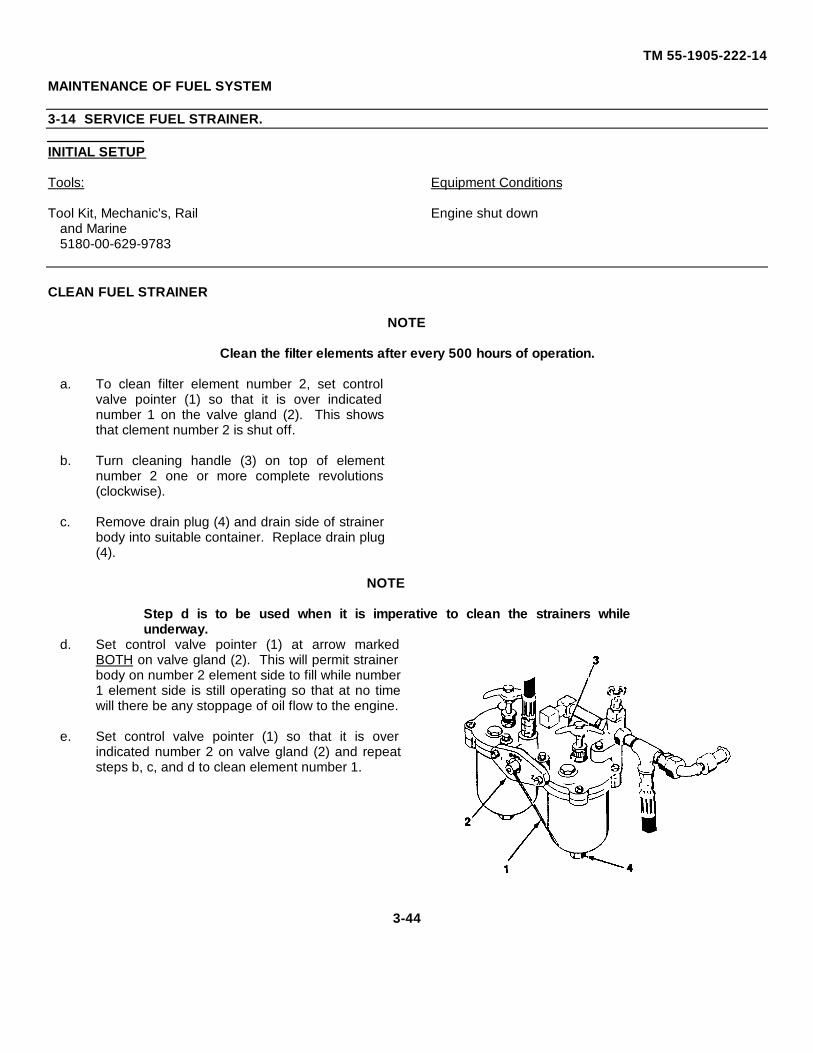
TM 55-1905-222-14
MAINTENANCE OF FUEL SYSTEM
3-14 SERVICE FUEL STRAINER.
INITIAL SETUP
Tools: Equipment Conditions
Tool Kit, Mechanic's, Rail Engine shut downand Marine5180-00-629-9783
CLEAN FUEL STRAINER
NOTE
Clean the filter elements after every 500 hours of operation.
a. To clean filter element number 2, set controlvalve pointer (1) so that it is over indicatednumber 1 on the valve gland (2). This showsthat clement number 2 is shut off.
b. Turn cleaning handle (3) on top of elementnumber 2 one or more complete revolutions(clockwise).
c. Remove drain plug (4) and drain side of strainerbody into suitable container. Replace drain plug(4).
NOTE
Step d is to be used when it is imperative to clean the strainers whileunderway.
d. Set control valve pointer (1) at arrow markedBOTH on valve gland (2). This will permit strainerbody on number 2 element side to fill while number1 element side is still operating so that at no timewill there be any stoppage of oil flow to the engine.
e. Set control valve pointer (1) so that it is overindicated number 2 on valve gland (2) and repeatsteps b, c, and d to clean element number 1.
3-44
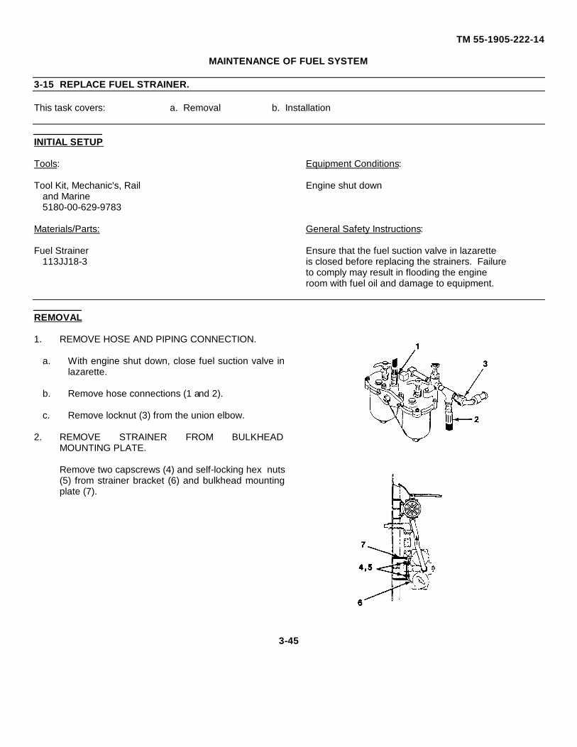
TM 55-1905-222-14
MAINTENANCE OF FUEL SYSTEM
3-15 REPLACE FUEL STRAINER.
This task covers: a. Removal b. Installation
INITIAL SETUP
Tools: Equipment Conditions:
Tool Kit, Mechanic's, Rail Engine shut downand Marine5180-00-629-9783
Materials/Parts: General Safety Instructions:
Fuel Strainer Ensure that the fuel suction valve in lazarette113JJ18-3 is closed before replacing the strainers. Failure
to comply may result in flooding the engineroom with fuel oil and damage to equipment.
REMOVAL
1. REMOVE HOSE AND PIPING CONNECTION.
a. With engine shut down, close fuel suction valve inlazarette.
b. Remove hose connections (1 and 2).
c. Remove locknut (3) from the union elbow.
2. REMOVE STRAINER FROM BULKHEADMOUNTING PLATE.
Remove two capscrews (4) and self-locking hex nuts(5) from strainer bracket (6) and bulkhead mountingplate (7).
3-45
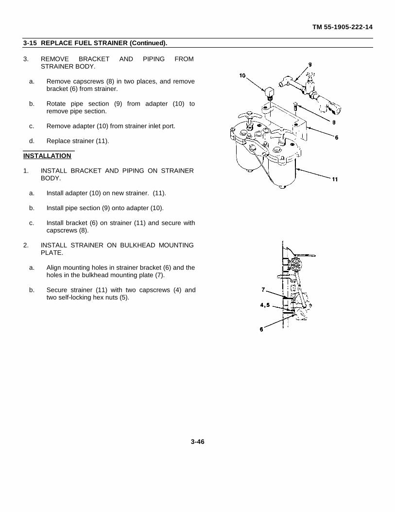
TM 55-1905-222-14
3-15 REPLACE FUEL STRAINER (Continued).
3. REMOVE BRACKET AND PIPING FROMSTRAINER BODY.
a. Remove capscrews (8) in two places, and removebracket (6) from strainer.
b. Rotate pipe section (9) from adapter (10) toremove pipe section.
c. Remove adapter (10) from strainer inlet port.
d. Replace strainer (11).
INSTALLATION
1. INSTALL BRACKET AND PIPING ON STRAINERBODY.
a. Install adapter (10) on new strainer. (11).
b. Install pipe section (9) onto adapter (10).
c. Install bracket (6) on strainer (11) and secure withcapscrews (8).
2. INSTALL STRAINER ON BULKHEAD MOUNTINGPLATE.
a. Align mounting holes in strainer bracket (6) and theholes in the bulkhead mounting plate (7).
b. Secure strainer (11) with two capscrews (4) andtwo self-locking hex nuts (5).
3-46
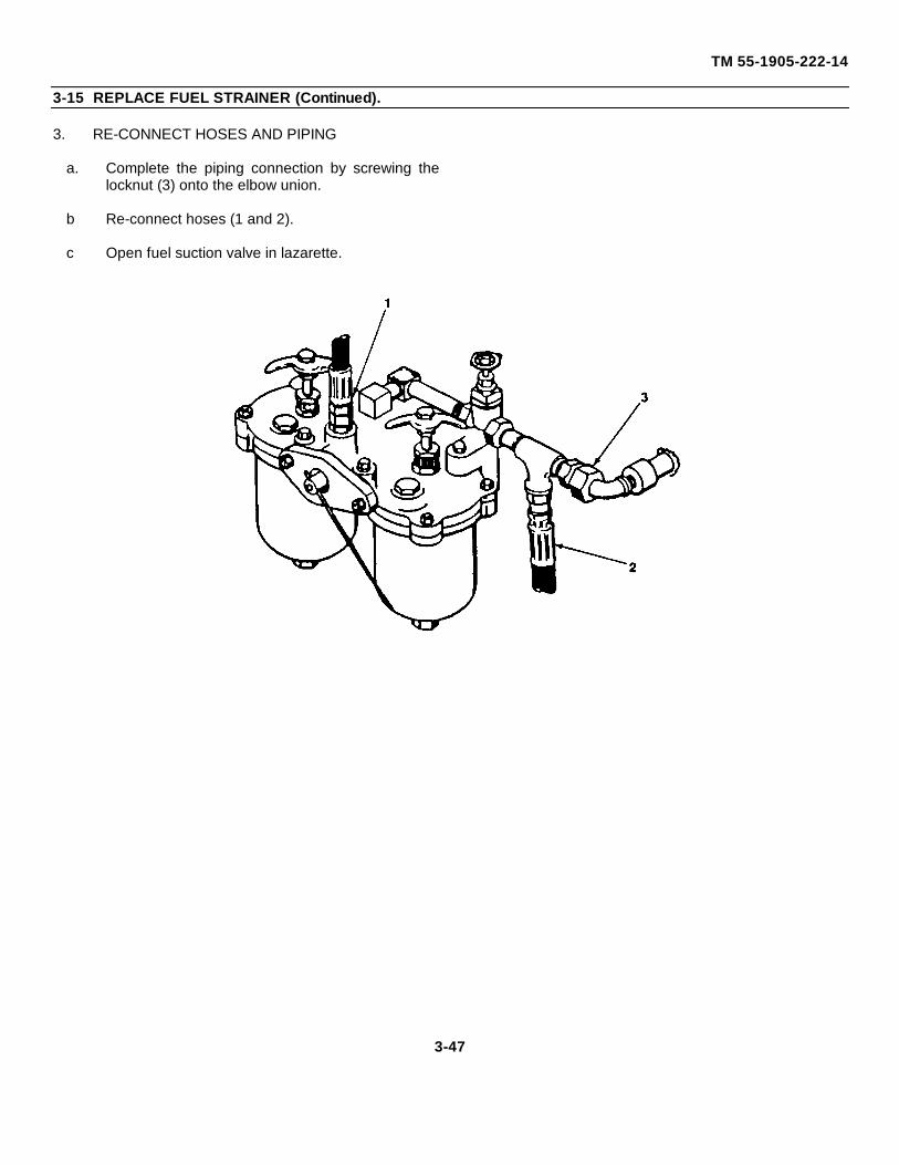
TM 55-1905-222-14
3-15 REPLACE FUEL STRAINER (Continued).
3. RE-CONNECT HOSES AND PIPING
a. Complete the piping connection by screwing thelocknut (3) onto the elbow union.
b Re-connect hoses (1 and 2).
c Open fuel suction valve in lazarette.
3-47
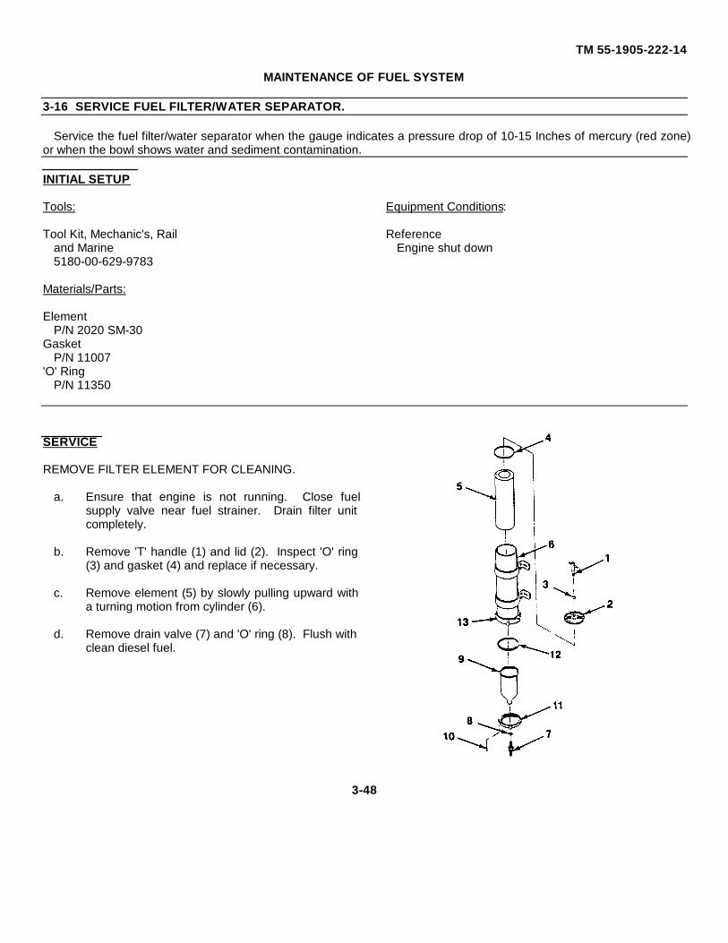
TM 55-1905-222-14
MAINTENANCE OF FUEL SYSTEM
3-16 SERVICE FUEL FILTER/WATER SEPARATOR.
Service the fuel filter/water separator when the gauge indicates a pressure drop of 10-15 Inches of mercury (red zone)or when the bowl shows water and sediment contamination.
INITIAL SETUP
Tools: Equipment Conditions:
Tool Kit, Mechanic's, Rail Referenceand Marine Engine shut down5180-00-629-9783
Materials/Parts:
ElementP/N 2020 SM-30
GasketP/N 11007
'O' RingP/N 11350
SERVICE
REMOVE FILTER ELEMENT FOR CLEANING.
a. Ensure that engine is not running. Close fuelsupply valve near fuel strainer. Drain filter unitcompletely.
b. Remove 'T' handle (1) and lid (2). Inspect 'O' ring(3) and gasket (4) and replace if necessary.
c. Remove element (5) by slowly pulling upward witha turning motion from cylinder (6).
d. Remove drain valve (7) and 'O' ring (8). Flush withclean diesel fuel.
3-48
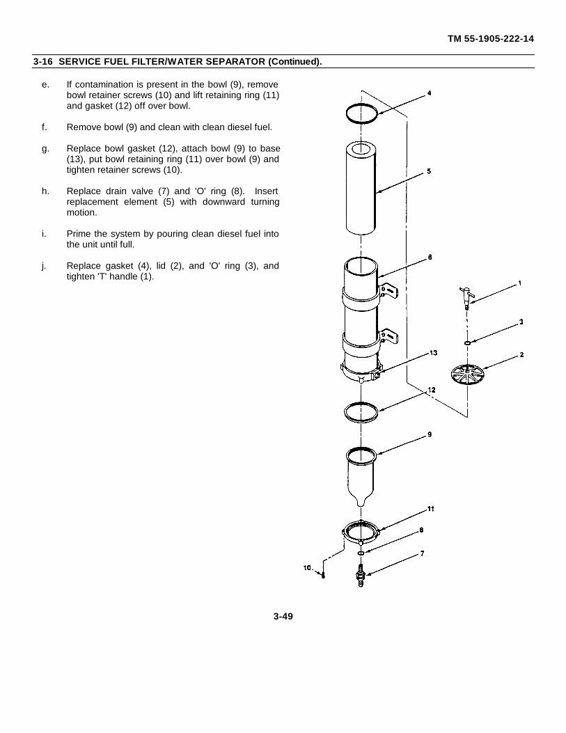
TM 55-1905-222-14
3-16 SERVICE FUEL FILTER/WATER SEPARATOR (Continued).
e. If contamination is present in the bowl (9), removebowl retainer screws (10) and lift retaining ring (11)and gasket (12) off over bowl.
f. Remove bowl (9) and clean with clean diesel fuel.
g. Replace bowl gasket (12), attach bowl (9) to base(13), put bowl retaining ring (11) over bowl (9) andtighten retainer screws (10).
h. Replace drain valve (7) and 'O' ring (8). Insertreplacement element (5) with downward turningmotion.
i. Prime the system by pouring clean diesel fuel intothe unit until full.
j. Replace gasket (4), lid (2), and 'O' ring (3), andtighten 'T' handle (1).
3-49
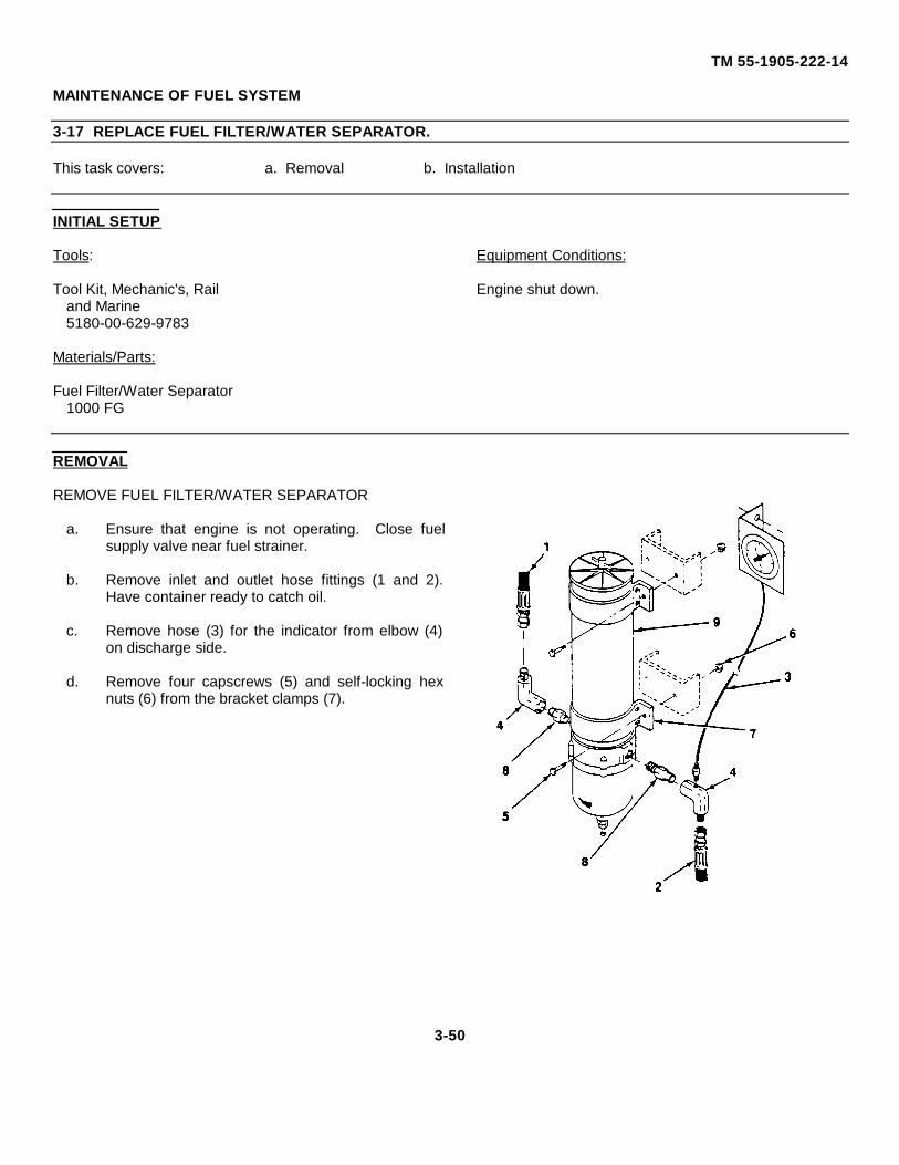
TM 55-1905-222-14
MAINTENANCE OF FUEL SYSTEM
3-17 REPLACE FUEL FILTER/WATER SEPARATOR.
This task covers: a. Removal b. Installation
INITIAL SETUP
Tools: Equipment Conditions:
Tool Kit, Mechanic's, Rail Engine shut down.and Marine5180-00-629-9783
Materials/Parts:
Fuel Filter/Water Separator1000 FG
REMOVAL
REMOVE FUEL FILTER/WATER SEPARATOR
a. Ensure that engine is not operating. Close fuelsupply valve near fuel strainer.
b. Remove inlet and outlet hose fittings (1 and 2).Have container ready to catch oil.
c. Remove hose (3) for the indicator from elbow (4)on discharge side.
d. Remove four capscrews (5) and self-locking hexnuts (6) from the bracket clamps (7).
3-50
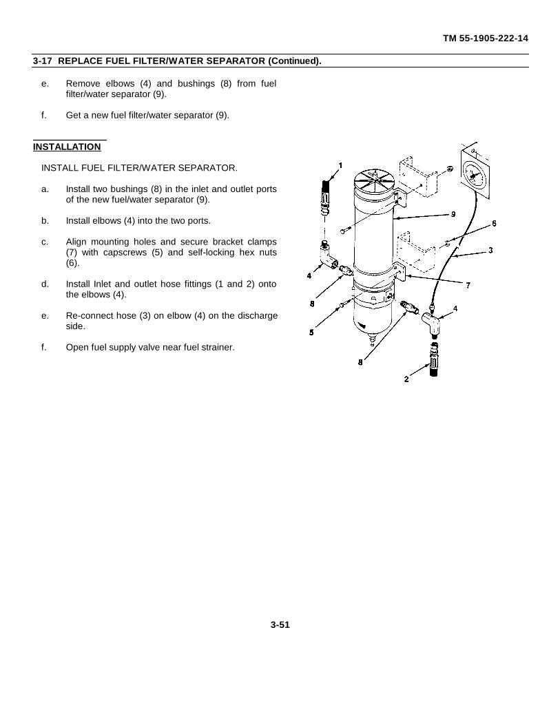
TM 55-1905-222-14
3-17 REPLACE FUEL FILTER/WATER SEPARATOR (Continued).
e. Remove elbows (4) and bushings (8) from fuelfilter/water separator (9).
f. Get a new fuel filter/water separator (9).
INSTALLATION
INSTALL FUEL FILTER/WATER SEPARATOR.
a. Install two bushings (8) in the inlet and outlet portsof the new fuel/water separator (9).
b. Install elbows (4) into the two ports.
c. Align mounting holes and secure bracket clamps(7) with capscrews (5) and self-locking hex nuts(6).
d. Install Inlet and outlet hose fittings (1 and 2) ontothe elbows (4).
e. Re-connect hose (3) on elbow (4) on the dischargeside.
f. Open fuel supply valve near fuel strainer.
3-51
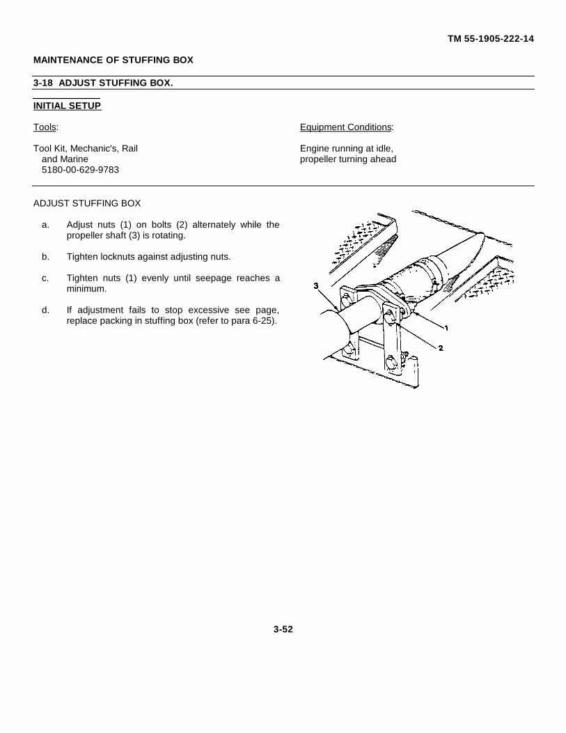
TM 55-1905-222-14
MAINTENANCE OF STUFFING BOX
3-18 ADJUST STUFFING BOX.
INITIAL SETUP
Tools: Equipment Conditions:
Tool Kit, Mechanic's, Rail Engine running at idle,and Marine propeller turning ahead5180-00-629-9783
ADJUST STUFFING BOX
a. Adjust nuts (1) on bolts (2) alternately while thepropeller shaft (3) is rotating.
b. Tighten locknuts against adjusting nuts.
c. Tighten nuts (1) evenly until seepage reaches aminimum.
d. If adjustment fails to stop excessive see page,replace packing in stuffing box (refer to para 6-25).
3-52

CHAPTER 4
UNIT MAINTENANCE
Paragraph
Adjust Clutch Linkage................................ ................................ ................................ ................... 4-24
Adjust Counterbalance Valve................................ ................................ ................................ ........ 4-32
Adjust Throttle Linkage................................ ................................ ................................ ................. 4-23
Adjust Voltage Regulator................................ ................................ ................................ .............. 4-13
Common Tools and Equipment................................ ................................ ................................ ..... 4-1
General Maintenance Procedures................................ ................................ ................................ . 4-6
Preventive Maintenance Checks and Services Procedures................................ ........................... 4-4
Repair Control and Distribution Panel................................ ................................ ........................... 4-16
Repair MSD Pump/Motor Assembly................................ ................................ .............................. 4-29
Repair Parts ................................ ................................ ................................ ................................ . 4-3
Replace Alternator................................ ................................ ................................ ........................ 4-12
Replace Batteries and Cables................................ ................................ ................................ ....... 4-11
Replace Canopy................................ ................................ ................................ ........................... 4-18
Replace Check Valve (Steering System) ................................ ................................ ...................... 4-33
Replace Electric Horn................................ ................................ ................................ ................... 4-9
Replace Engine Shutdown Controls (Air and Fuel)................................ ................................ ........ 4-25
Replace Filter, Disinfection Unit and Retention Canisters ................................ ............................. 4-27
Replace Hoses and Fittings................................. ................................ ................................ ......... 4-30
Replace Mast................................ ................................ ................................ ................................ 4-20
Replace MSD Pump and Motor Assembly ................................ ................................ .................... 4-28
Replace Navigation Light Fixtures and Switches................................ ................................ ........... 4-7
Replace Propulsion Control Head................................ ................................ ................................ . 4-22
Replace/Repair Exhaust Piping and Muffler................................ ................................ .................. 4-34
Replace/Repair Lighting Fixtures and Switches................................ ................................ ............ 4-17
4-1
TM 55-1905-222-14
CHAPTER 4
UNIT MAINTENANCE - Continued
Paragraph
Replace Searchlight Bulb, Reflector Glass and Fixture................................ ................................ . 4-8
Replace Voltage Protector................................ ................................ ................................ ............ 4-15
Replace Treatment Tank ................................ ................................ ................................ .............. 4-26
Replace Voltage Regulator................................ ................................ ................................ ........... 4-14
Replace Window................................ ................................ ................................ ........................... 4-19
Replace Windshield Wipers and Wiper Motor................................ ................................ ............... 4-21
Service Level Indicator ................................ ................................ ................................ ................. 4-31
Service of Rudder and Tiller ................................ ................................ ................................ ......... 4-35
Special Tools, TMDE and Support Equipment................................ ................................ .............. 4-2
Test Batteries ................................ ................................ ................................ ............................... 4-10
Troubleshooting Procedures................................ ................................ ................................ ......... 4-5
4-2
TM 55-1905-222-14
Section I. REPAIR PARTS; SPECIAL TOOLS; TEST, MEASUREMENT AND DIAGNOSTICEQUIPMENT (TMDE); AND SUPPORT EQUIPNIENT
4-1 COMMON TOOLS AND EQUIPMENT.
For authorized common tools and equipment, refer to the Modified Table of Organizational Equipment (MTOE)applicable to your unit.
4-2 SPECIAL TOOLS, TMDE AND SUPPORT EQUIPMENT.
Any special tools or equipment required by organizational maintenance personnel to perform maintenance on thelanding craft Is listed in Appendix B of this manual.
4-3 REPAIR PARTS.
Repair parts are listed and illustrated in the repair parts and special tools list (TM 55-1905-222-24P) coveringorganizational maintenance of this equipment.
Section II. UNIT PREVENTIVE MAINTENANCE CHECKS AND SERVICES
4-4 PREVENTIVE MAINTENANCE CHECKS AND SERVICES PROCEDURES.
a. Your PMCS table lists the inspections and care required to keep the LCM-8 in good operating condition.
b. The interval column of your PMCS table tells you when to do a certain check or service.
c. The procedure column of your PMCS table tells you how to do the required checks and services. Carefully followthese procedures. If you do not have the equipment to perform these procedures, seek assistance from the nexthigher maintenance level.
d. If your equipment requires removal in order to perform PMCS, refer to chapter 4 under maintenance instructionsand notify your supervisor.
4-3
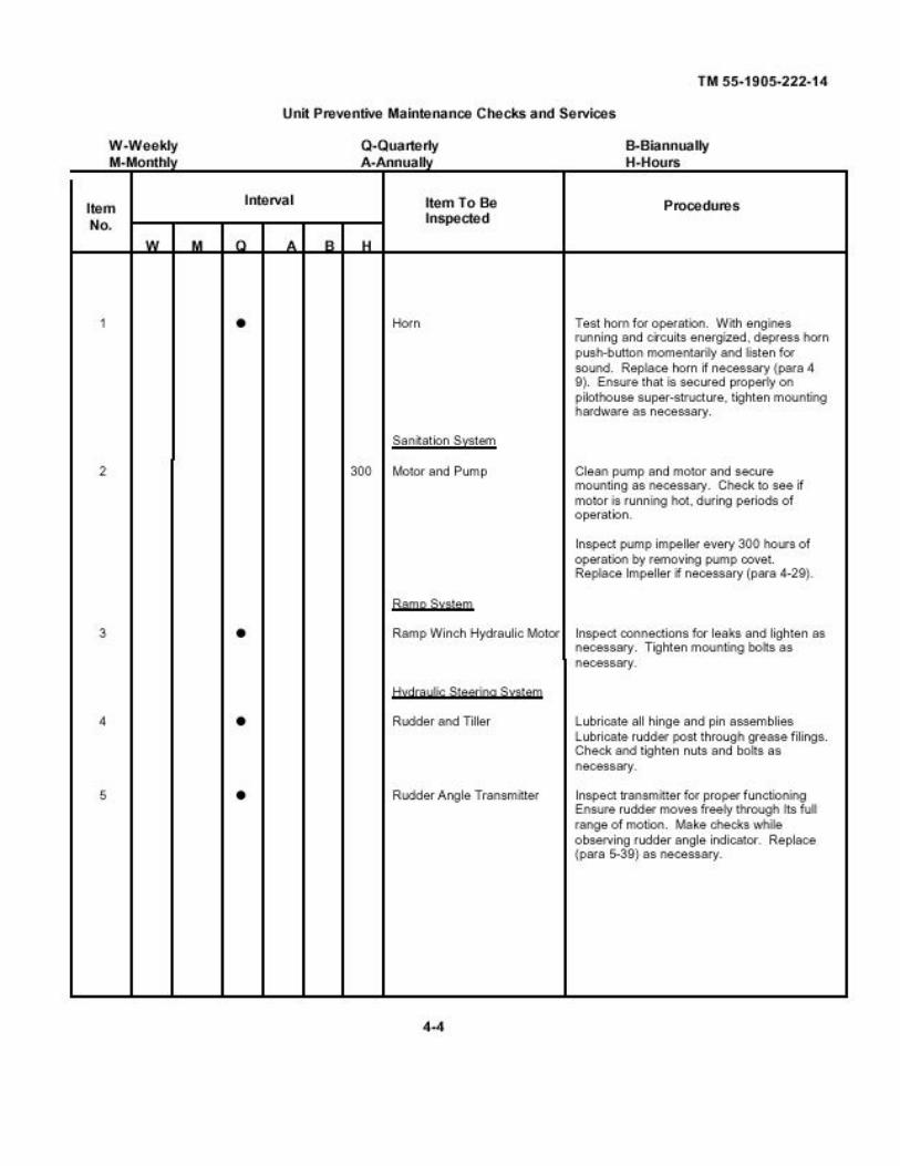
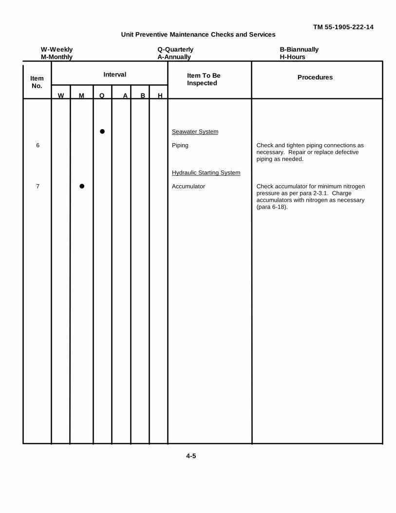
TM 55-1905-222-14Unit Preventive Maintenance Checks and Services
W-Weekly Q-Quarterly B-BiannuallyM-Monthly A-Annually H-Hours
W M Q A B H
● Seawater System
6 Piping Check and tighten piping connections asnecessary. Repair or replace defectivepiping as needed.
Hydraulic Starting System
7 ● Accumulator Check accumulator for minimum nitrogenpressure as per para 2-3.1. Chargeaccumulators with nitrogen as necessary(para 6-18).
Item To BeInspected
IntervalItemNo.
Procedures
4-5
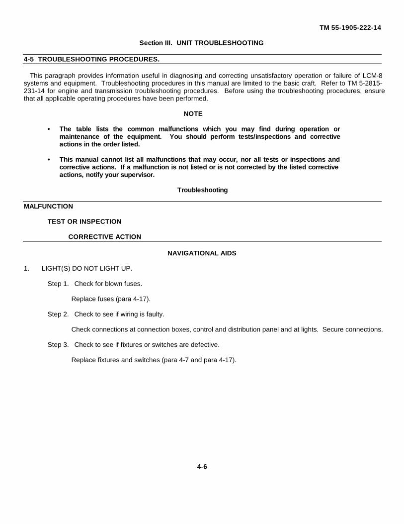
TM 55-1905-222-14
Section III. UNIT TROUBLESHOOTING
4-5 TROUBLESHOOTING PROCEDURES.
This paragraph provides information useful in diagnosing and correcting unsatisfactory operation or failure of LCM-8systems and equipment. Troubleshooting procedures in this manual are limited to the basic craft. Refer to TM 5-2815-231-14 for engine and transmission troubleshooting procedures. Before using the troubleshooting procedures, ensurethat all applicable operating procedures have been performed.
NOTE
· The table lists the common malfunctions which you may find during operation ormaintenance of the equipment. You should perform tests/inspections and correctiveactions in the order listed.
· This manual cannot list all malfunctions that may occur, nor all tests or inspections and
corrective actions. If a malfunction is not listed or is not corrected by the listed correctiveactions, notify your supervisor.
Troubleshooting
MALFUNCTION
TEST OR INSPECTION
CORRECTIVE ACTION
NAVIGATIONAL AIDS
1. LIGHT(S) DO NOT LIGHT UP.
Step 1. Check for blown fuses.
Replace fuses (para 4-17).
Step 2. Check to see if wiring is faulty.
Check connections at connection boxes, control and distribution panel and at lights. Secure connections.
Step 3. Check to see if fixtures or switches are defective.
Replace fixtures and switches (para 4-7 and para 4-17).
4-6
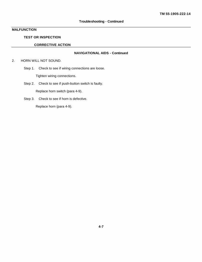
TM 55-1905-222-14
Troubleshooting - Continued
MALFUNCTION
TEST OR INSPECTION
CORRECTIVE ACTION
NAVIGATIONAL AIDS - Continued
2. HORN WILL NOT SOUND.
Step 1. Check to see if wiring connections are loose.
Tighten wiring connections.
Step 2. Check to see if push-button switch is faulty.
Replace horn switch (para 4-9).
Step 3. Check to see if horn is defective.
Replace horn (para 4-9).
4-7
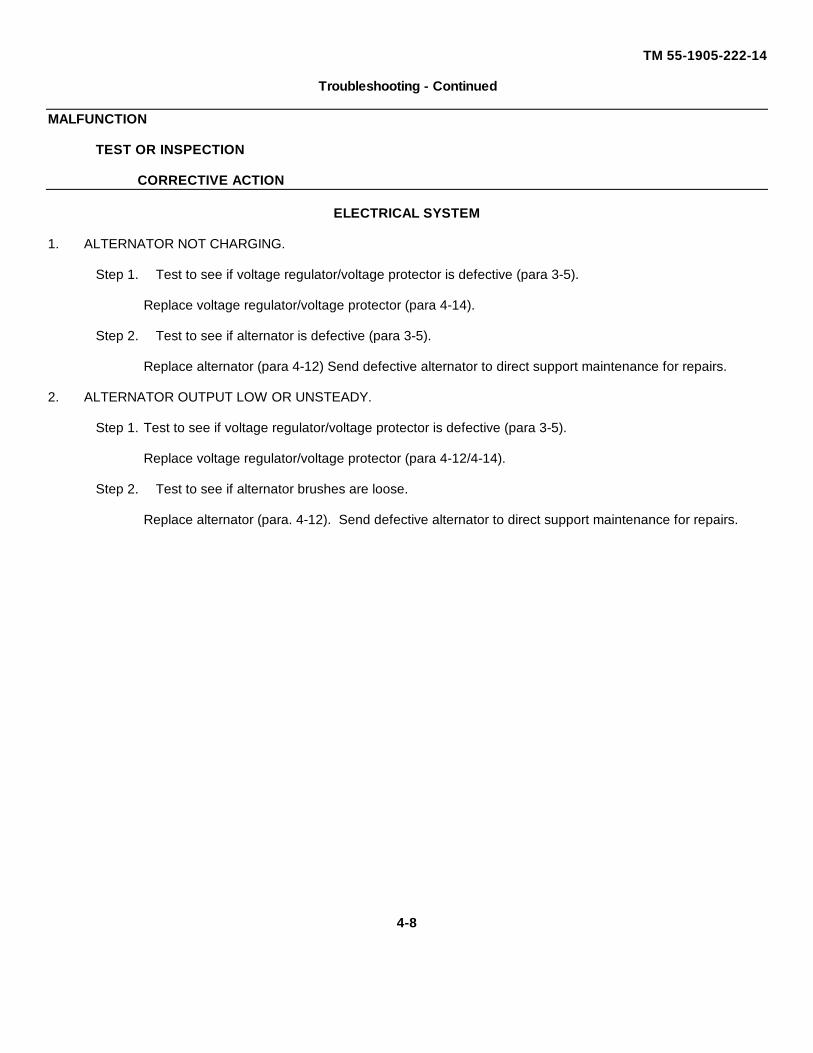
TM 55-1905-222-14
Troubleshooting - Continued
MALFUNCTION
TEST OR INSPECTION
CORRECTIVE ACTION
ELECTRICAL SYSTEM
1. ALTERNATOR NOT CHARGING.
Step 1. Test to see if voltage regulator/voltage protector is defective (para 3-5).
Replace voltage regulator/voltage protector (para 4-14).
Step 2. Test to see if alternator is defective (para 3-5).
Replace alternator (para 4-12) Send defective alternator to direct support maintenance for repairs.
2. ALTERNATOR OUTPUT LOW OR UNSTEADY.
Step 1. Test to see if voltage regulator/voltage protector is defective (para 3-5).
Replace voltage regulator/voltage protector (para 4-12/4-14).
Step 2. Test to see if alternator brushes are loose.
Replace alternator (para. 4-12). Send defective alternator to direct support maintenance for repairs.
4-8
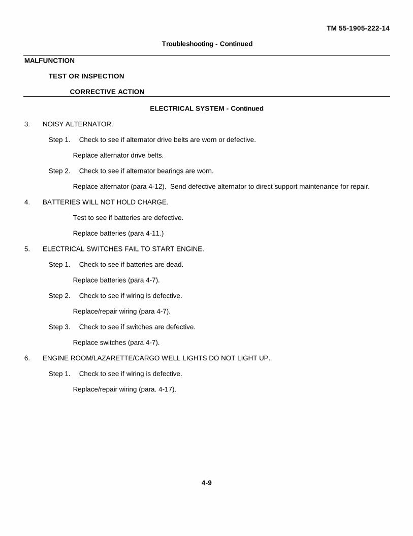
TM 55-1905-222-14
Troubleshooting - Continued
MALFUNCTION
TEST OR INSPECTION
CORRECTIVE ACTION
ELECTRICAL SYSTEM - Continued
3. NOISY ALTERNATOR.
Step 1. Check to see if alternator drive belts are worn or defective.
Replace alternator drive belts.
Step 2. Check to see if alternator bearings are worn.
Replace alternator (para 4-12). Send defective alternator to direct support maintenance for repair.
4. BATTERIES WILL NOT HOLD CHARGE.
Test to see if batteries are defective.
Replace batteries (para 4-11.)
5. ELECTRICAL SWITCHES FAIL TO START ENGINE.
Step 1. Check to see if batteries are dead.
Replace batteries (para 4-7).
Step 2. Check to see if wiring is defective.
Replace/repair wiring (para 4-7).
Step 3. Check to see if switches are defective.
Replace switches (para 4-7).
6. ENGINE ROOM/LAZARETTE/CARGO WELL LIGHTS DO NOT LIGHT UP.
Step 1. Check to see if wiring is defective.
Replace/repair wiring (para. 4-17).
4-9
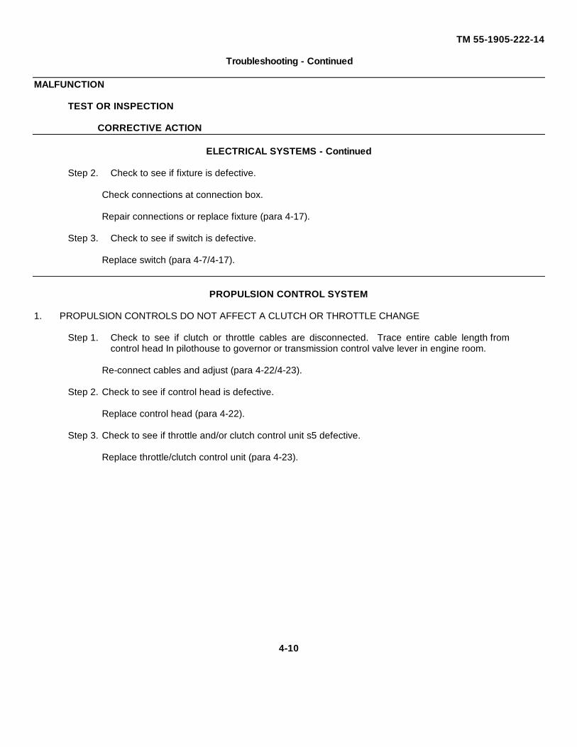
TM 55-1905-222-14
Troubleshooting - Continued
MALFUNCTION
TEST OR INSPECTION
CORRECTIVE ACTION
ELECTRICAL SYSTEMS - Continued
Step 2. Check to see if fixture is defective.
Check connections at connection box.
Repair connections or replace fixture (para 4-17).
Step 3. Check to see if switch is defective.
Replace switch (para 4-7/4-17).
PROPULSION CONTROL SYSTEM
1. PROPULSION CONTROLS DO NOT AFFECT A CLUTCH OR THROTTLE CHANGE
Step 1. Check to see if clutch or throttle cables are disconnected. Trace entire cable length fromcontrol head In pilothouse to governor or transmission control valve lever in engine room.
Re-connect cables and adjust (para 4-22/4-23).
Step 2. Check to see if control head is defective.
Replace control head (para 4-22).
Step 3. Check to see if throttle and/or clutch control unit s5 defective.
Replace throttle/clutch control unit (para 4-23).
4-10
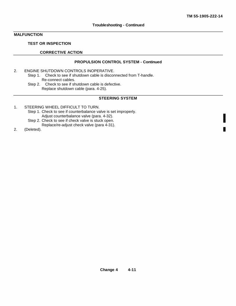
TM 55-1905-222-14
Troubleshooting - Continued
MALFUNCTION
TEST OR INSPECTION
CORRECTIVE ACTION
PROPULSION CONTROL SYSTEM - Continued
2. ENGINE SHUTDOWN CONTROLS INOPERATIVE.Step 1. Check to see if shutdown cable is disconnected from T-handle.
Re-connect cables.Step 2. Check to see if shutdown cable is defective.
Replace shutdown cable (para. 4-25).
STEERING SYSTEM
1. STEERING WHEEL DIFFICULT TO TURN.Step 1. Check to see if counterbalance valve is set improperly.
Adjust counterbalance valve (para. 4-32).Step 2. Check to see if check valve is stuck open.
Replace/re-adjust check valve (para 4-31).2. (Deleted).
Change 4 4-11
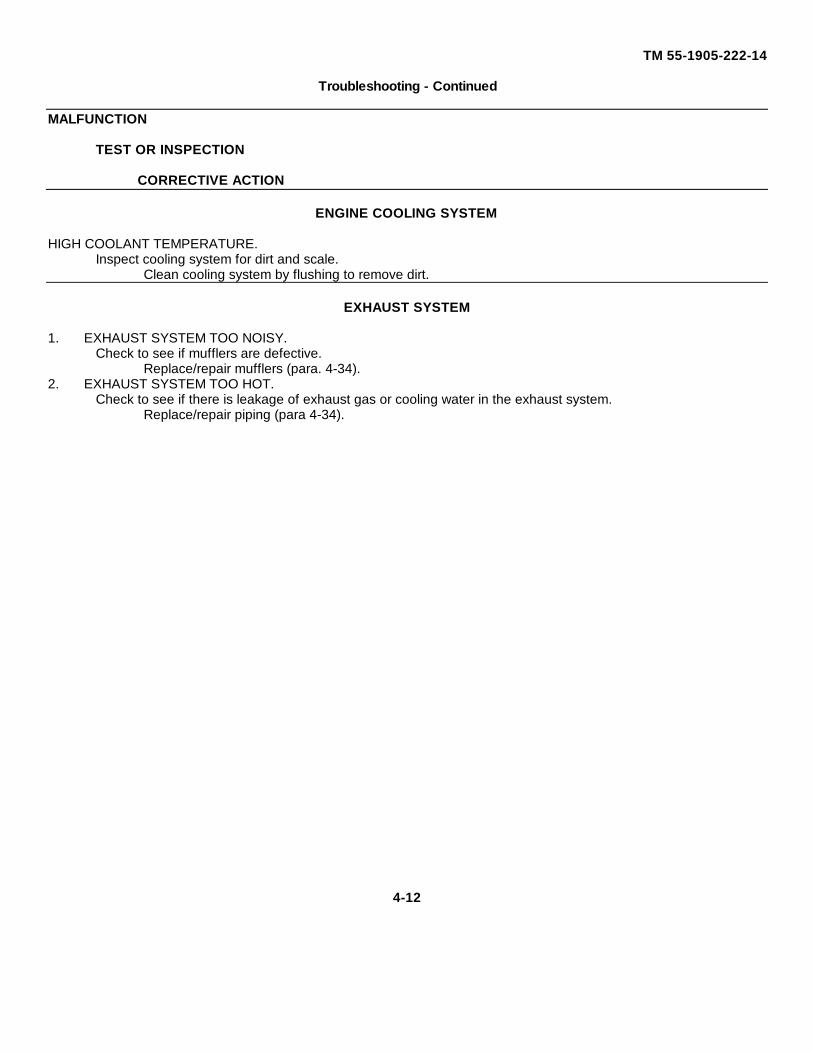
TM 55-1905-222-14
Troubleshooting - Continued
MALFUNCTION
TEST OR INSPECTION
CORRECTIVE ACTION
ENGINE COOLING SYSTEM
HIGH COOLANT TEMPERATURE.Inspect cooling system for dirt and scale.
Clean cooling system by flushing to remove dirt.
EXHAUST SYSTEM
1. EXHAUST SYSTEM TOO NOISY.Check to see if mufflers are defective.
Replace/repair mufflers (para. 4-34).2. EXHAUST SYSTEM TOO HOT.
Check to see if there is leakage of exhaust gas or cooling water in the exhaust system.Replace/repair piping (para 4-34).
4-12

TM 55-1905-222-14
Section IV. UNIT NMAINTENANCE PROCEDURES
4-6 GENERAL MAINTENANCE PROCEDURES.
This section contains maintenance procedures that are the responsibility of unit maintenance personnel as authorizedby the Maintenance Allocation Chart (MAC).
4-13
TM 55-1905-222-14
MAINTENANCE OF NAVIGATION LIGHTS
4-7 REPLACE NAVIGATION LIGHT FIXTURES AND SWITCHES.
This task covers: a. Removal b. Installation
INITIAL SETUP
Tools: Equipment Conditions:
Tool Kit, Mechanic's, Rail All power offand Marine5180-00-629-9783
Materials/Parts: General Safety Instructions:
Light, 3600, White w/24v Bulb Energized electrical equipment isP/N 33506-033 dangerous Never work on energized
Light, 3600, Red w/24v Bulb equipment unless authorized to doP/N 33506-233 so by a responsible authority.
Light, Masthead w/24v BulbP/N 33501-003
Light, Port, w/24v BulbP/N 33504-203
Light, Stern w/24v BulbP/N 33502-003
Light, Starboard w/24v BulbP/N 33505-103
REMOVAL
WARNING
De-energize all navigation lights at the control and distribution panel in thepilothouse. Energized circuits during replacement may result in injury ordamage to personnel and equipment.
4-14
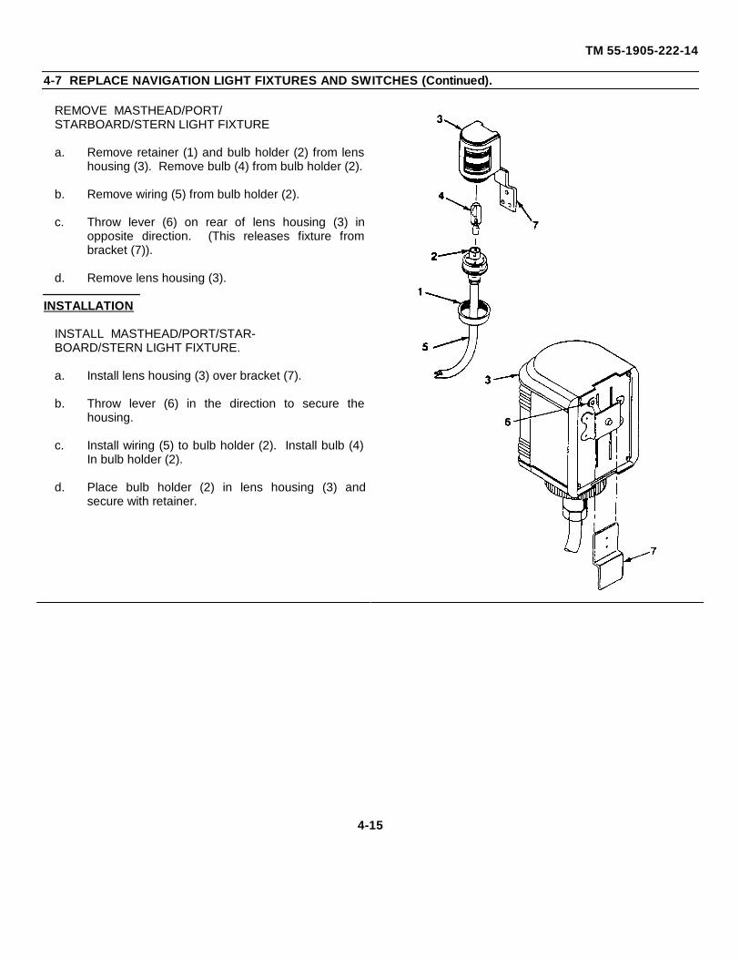
TM 55-1905-222-14
4-7 REPLACE NAVIGATION LIGHT FIXTURES AND SWITCHES (Continued).
REMOVE MASTHEAD/PORT/STARBOARD/STERN LIGHT FIXTURE
a. Remove retainer (1) and bulb holder (2) from lenshousing (3). Remove bulb (4) from bulb holder (2).
b. Remove wiring (5) from bulb holder (2).
c. Throw lever (6) on rear of lens housing (3) inopposite direction. (This releases fixture frombracket (7)).
d. Remove lens housing (3).
INSTALLATION
INSTALL MASTHEAD/PORT/STAR-BOARD/STERN LIGHT FIXTURE.
a. Install lens housing (3) over bracket (7).
b. Throw lever (6) in the direction to secure thehousing.
c. Install wiring (5) to bulb holder (2). Install bulb (4)In bulb holder (2).
d. Place bulb holder (2) in lens housing (3) andsecure with retainer.
4-15
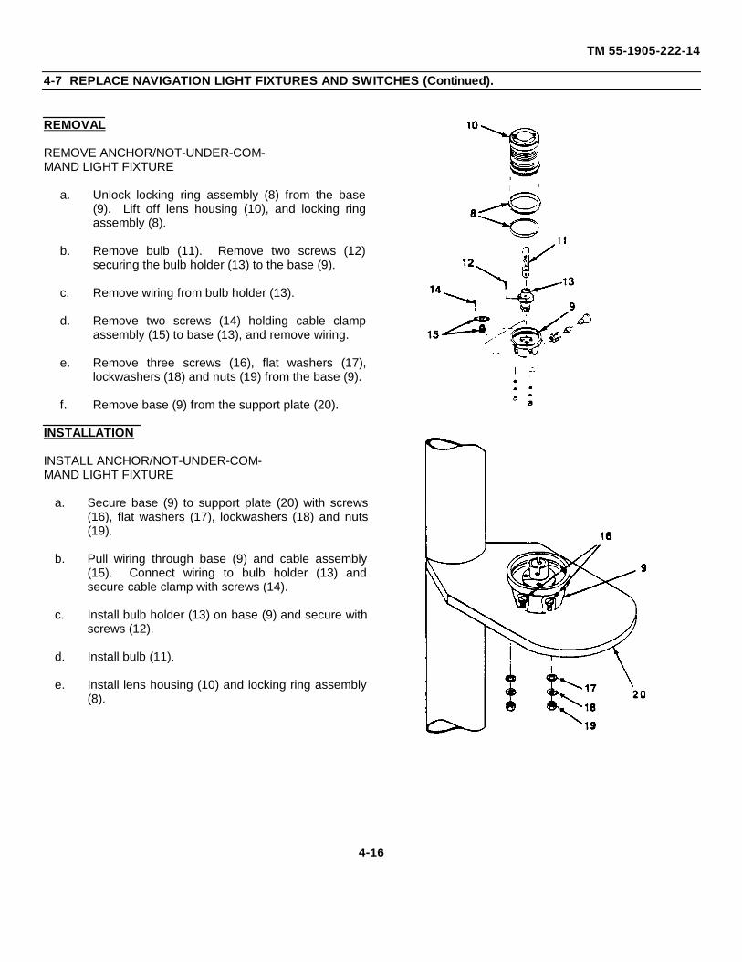
TM 55-1905-222-14
4-7 REPLACE NAVIGATION LIGHT FIXTURES AND SWITCHES (Continued).
REMOVAL
REMOVE ANCHOR/NOT-UNDER-COM-MAND LIGHT FIXTURE
a. Unlock locking ring assembly (8) from the base(9). Lift off lens housing (10), and locking ringassembly (8).
b. Remove bulb (11). Remove two screws (12)securing the bulb holder (13) to the base (9).
c. Remove wiring from bulb holder (13).
d. Remove two screws (14) holding cable clampassembly (15) to base (13), and remove wiring.
e. Remove three screws (16), flat washers (17),lockwashers (18) and nuts (19) from the base (9).
f. Remove base (9) from the support plate (20).
INSTALLATION
INSTALL ANCHOR/NOT-UNDER-COM-MAND LIGHT FIXTURE
a. Secure base (9) to support plate (20) with screws(16), flat washers (17), lockwashers (18) and nuts(19).
b. Pull wiring through base (9) and cable assembly(15). Connect wiring to bulb holder (13) andsecure cable clamp with screws (14).
c. Install bulb holder (13) on base (9) and secure withscrews (12).
d. Install bulb (11).
e. Install lens housing (10) and locking ring assembly(8).
4-16
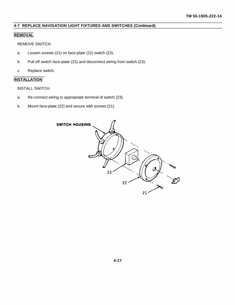
TM 55-1905-222-14
4-7 REPLACE NAVIGATION LIGHT FIXTURES AND SWITCHES (Continued).
REMOVAL
REMOVE SWITCH.
a. Loosen screws (21) on face-plate (22) switch (23).
b. Pull off switch face-plate (22) and disconnect wiring from switch (23).
c. Replace switch.
INSTALLATION
INSTALL SWITCH.
a. Re-connect wiring to appropriate terminal of switch (23).
b. Mount face-plate (22) and secure with screws (21).
4-17
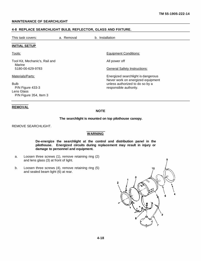
TM 55-1905-222-14
MAINTENANCE OF SEARCHLIGHT
4-8 REPLACE SEARCHLIGHT BULB, REFLECTOR, GLASS AND FIXTURE.
This task covers: a. Removal b. Installation
INITIAL SETUP
Tools: Equipment Conditions:
Tool Kit, Mechanic's, Rail and All power offMarine5180-00-629-9783 General Safety Instructions:
Materials/Parts: Energized searchlight is dangerousNever work on energized equipment
Bulb unless authorized to do so by aP/N Figure 433-3 responsible authority.
Lens GlassP/N Figure 354, Item 3
REMOVALNOTE
The searchlight is mounted on top pilothouse canopy.
REMOVE SEARCHLIGHT.
WARNING
De-energize the searchlight at the control and distribution panel in thepilothouse. Energized circuits during replacement may result in injury ordamage to personnel and equipment.
a. Loosen three screws (1), remove retaining ring (2)and lens glass (3) at front of light.
b. Loosen three screws (4), remove retaining ring (5)and sealed beam light (6) at rear.
4-18
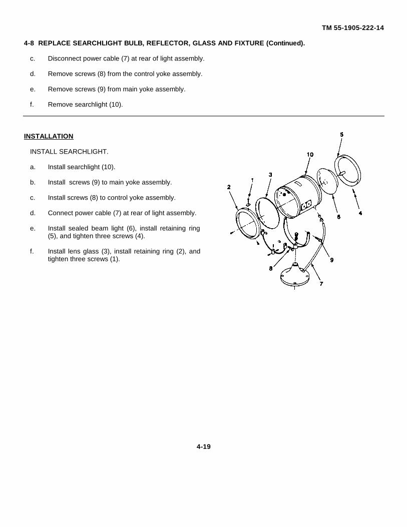
TM 55-1905-222-14
4-8 REPLACE SEARCHLIGHT BULB, REFLECTOR, GLASS AND FIXTURE (Continued).
c. Disconnect power cable (7) at rear of light assembly.
d. Remove screws (8) from the control yoke assembly.
e. Remove screws (9) from main yoke assembly.
f. Remove searchlight (10).
INSTALLATION
INSTALL SEARCHLIGHT.
a. Install searchlight (10).
b. Install screws (9) to main yoke assembly.
c. Install screws (8) to control yoke assembly.
d. Connect power cable (7) at rear of light assembly.
e. Install sealed beam light (6), install retaining ring(5), and tighten three screws (4).
f. Install lens glass (3), install retaining ring (2), andtighten three screws (1).
4-19
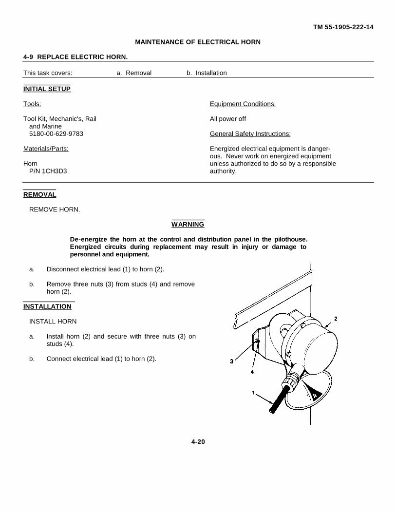
TM 55-1905-222-14
MAINTENANCE OF ELECTRICAL HORN
4-9 REPLACE ELECTRIC HORN.
This task covers: a. Removal b. Installation
INITIAL SETUP
Tools: Equipment Conditions:
Tool Kit, Mechanic's, Rail All power offand Marine5180-00-629-9783 General Safety Instructions:
Materials/Parts: Energized electrical equipment is danger-ous. Never work on energized equipment
Horn unless authorized to do so by a responsibleP/N 1CH3D3 authority.
REMOVAL
REMOVE HORN.
WARNING
De-energize the horn at the control and distribution panel in the pilothouse.Energized circuits during replacement may result in injury or damage topersonnel and equipment.
a. Disconnect electrical lead (1) to horn (2).
b. Remove three nuts (3) from studs (4) and removehorn (2).
INSTALLATION
INSTALL HORN
a. Install horn (2) and secure with three nuts (3) onstuds (4).
b. Connect electrical lead (1) to horn (2).
4-20
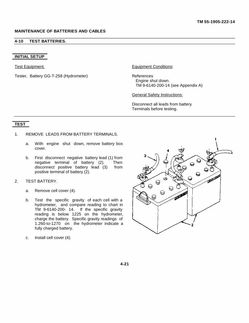
TM 55-1905-222-14
MAINTENANCE OF BATTERIES AND CABLES
4-10 TEST BATTERIES.
INITIAL SETUP
Test Equipment. Equipment Conditions:
Tester, Battery GG-T-258 (Hydrometer) ReferencesEngine shut down.TM 9-6140-200-14 (see Appendix A)
General Safety Instructions:
Disconnect all leads from batteryTerminals before testing.
TEST
1. REMOVE LEADS FROM BATTERY TERMINALS.
a. With engine shut down, remove battery boxcover.
b. First disconnect negative battery lead (1) fromnegative terminal of battery (2). Thendisconnect positive battery lead (3) frompositive terminal of battery (2).
2. TEST BATTERY.
a. Remove cell cover (4).
b. Test the specific gravity of each cell with ahydrometer, and compare reading to chart inTM 9-6140-200- 14. If the specific gravityreading is below 1225 on the hydrometer,charge the battery. Specific gravity readings of1.260-to-1270 on the hydrometer indicate afully charged battery.
c. Install cell cover (4).
4-21
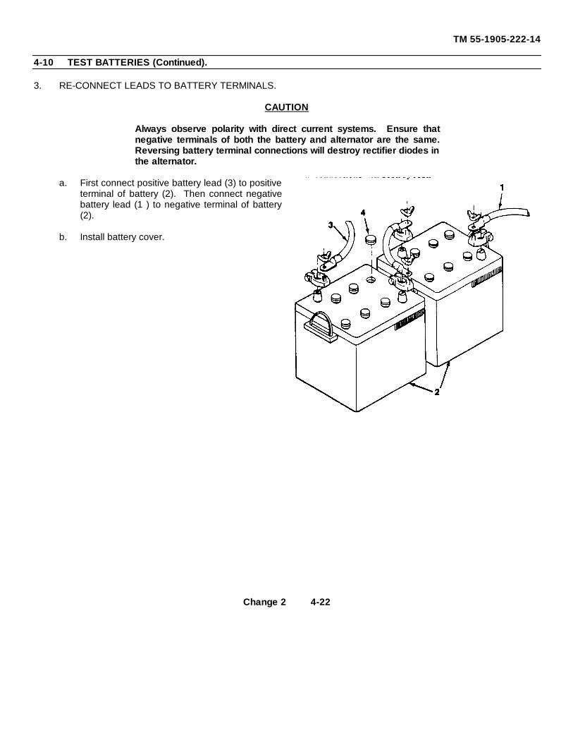
TM 55-1905-222-14
4-10 TEST BATTERIES (Continued).
3. RE-CONNECT LEADS TO BATTERY TERMINALS.
CAUTION
Always observe polarity with direct current systems. Ensure thatnegative terminals of both the battery and alternator are the same.Reversing battery terminal connections will destroy rectifier diodes inthe alternator.
a. First connect positive battery lead (3) to positiveterminal of battery (2). Then connect negativebattery lead (1 ) to negative terminal of battery(2).
b. Install battery cover.
Change 2 4-22
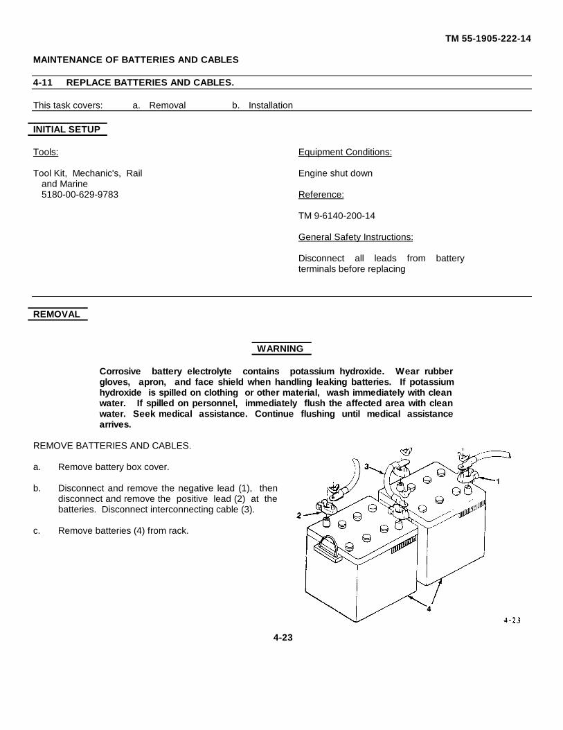
TM 55-1905-222-14
MAINTENANCE OF BATTERIES AND CABLES
4-11 REPLACE BATTERIES AND CABLES.
This task covers: a. Removal b. Installation
INITIAL SETUP
Tools: Equipment Conditions:
Tool Kit, Mechanic's, Rail Engine shut downand Marine5180-00-629-9783 Reference:
TM 9-6140-200-14
General Safety Instructions:
Disconnect all leads from batteryterminals before replacing
REMOVAL
WARNING
Corrosive battery electrolyte contains potassium hydroxide. Wear rubbergloves, apron, and face shield when handling leaking batteries. If potassiumhydroxide is spilled on clothing or other material, wash immediately with cleanwater. If spilled on personnel, immediately flush the affected area with cleanwater. Seek medical assistance. Continue flushing until medical assistancearrives.
REMOVE BATTERIES AND CABLES.
a. Remove battery box cover.
b. Disconnect and remove the negative lead (1), thendisconnect and remove the positive lead (2) at thebatteries. Disconnect interconnecting cable (3).
c. Remove batteries (4) from rack.
4-23
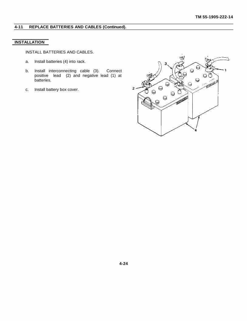
TM 55-1905-222-14
4-11 REPLACE BATTERIES AND CABLES (Continued).
INSTALLATION
INSTALL BATTERIES AND CABLES.
a. Install batteries (4) into rack.
b. Install interconnecting cable (3). Connectpositive lead (2) and negative lead (1) atbatteries.
c. Install battery box cover.
4-24
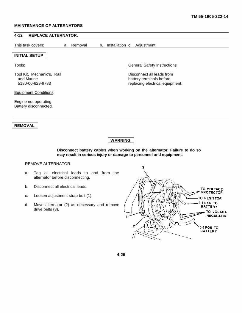
TM 55-1905-222-14
MAINTENANCE OF ALTERNATORS
4-12 REPLACE ALTERNATOR.
This task covers: a. Removal b. Installation c. Adjustment
INITIAL SETUP
Tools: General Safety Instructions:
Tool Kit, Mechanic's, Rail Disconnect all leads fromand Marine battery terminals before5180-00-629-9783 replacing electrical equipment.
Equipment Conditions:
Engine not operating.Battery disconnected.
REMOVAL
WARNING
Disconnect battery cables when working on the alternator. Failure to do somay result in serious injury or damage to personnel and equipment.
REMOVE ALTERNATOR
a. Tag all electrical leads to and from thealternator before disconnecting.
b. Disconnect all electrical leads.
c. Loosen adjustment strap bolt (1).
d. Move alternator (2) as necessary and removedrive belts (3).
4-25
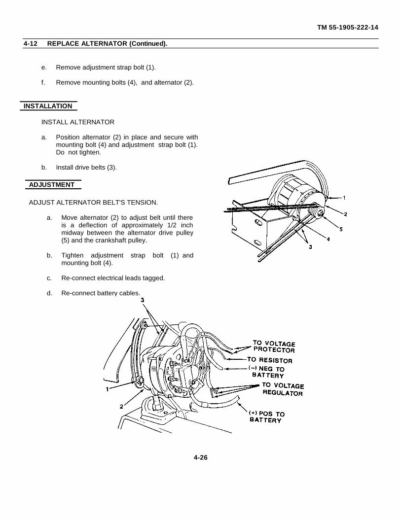
TM 55-1905-222-14
4-12 REPLACE ALTERNATOR (Continued).
e. Remove adjustment strap bolt (1).
f. Remove mounting bolts (4), and alternator (2).
INSTALLATION
INSTALL ALTERNATOR
a. Position alternator (2) in place and secure withmounting bolt (4) and adjustment strap bolt (1).Do not tighten.
b. Install drive belts (3).
ADJUSTMENT
ADJUST ALTERNATOR BELT'S TENSION.
a. Move alternator (2) to adjust belt until thereis a deflection of approximately 1/2 inchmidway between the alternator drive pulley(5) and the crankshaft pulley.
b. Tighten adjustment strap bolt (1) andmounting bolt (4).
c. Re-connect electrical leads tagged.
d. Re-connect battery cables.
4-26
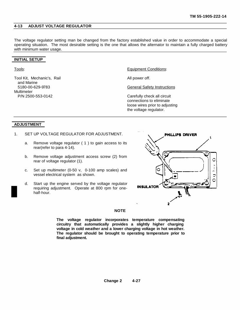
TM 55-1905-222-14
4-13 ADJUST VOLTAGE REGULATOR
The voltage regulator setting man be changed from the factory established value in order to accommodate a specialoperating situation. The most desirable setting is the one that allows the alternator to maintain a fully charged batterywith minimum water usage.
INITIAL SETUP
Tools: Equipment Conditions:
Tool Kit, Mechanic's, Rail All power off.and Marine5180-00-629-9783 General Safety Instructions
MultimeterP/N 2500-553-0142 Carefully check all circuit
connections to eliminateloose wires prior to adjustingthe voltage regulator.
ADJUSTMENT
1. SET UP VOLTAGE REGULATOR FOR ADJUSTMENT.
a. Remove voltage regulator ( 1 ) to gain access to itsrear(refer to para 4-14).
b. Remove voltage adjustment access screw (2) fromrear of voltage regulator (1).
c. Set up multimeter (0-50 v, 0-100 amp scales) andvessel electrical system as shown.
d. Start up the engine served by the voltage regulatorrequiring adjustment. Operate at 800 rpm for one-half-hour.
NOTE
The voltage regulator incorporates temperature compensatingcircuitry that automatically provides a slightly higher chargingvoltage in cold weather and a lower charging voltage in hot weather.The regulator should be brought to operating temperature prior tofinal adjustment.
Change 2 4-27
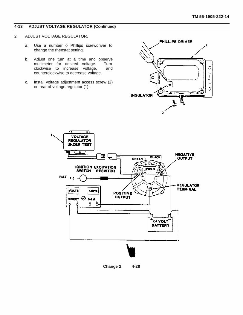
TM 55-1905-222-14
4-13 ADJUST VOLTAGE REGULATOR (Continued)
2. ADJUST VOLTAGE REGULATOR.
a. Use a number o Phillips screwdriver tochange the rheostat setting.
b. Adjust one turn at a time and observemultimeter for desired voltage. Turnclockwise to increase voltage, andcounterclockwise to decrease voltage.
c. Install voltage adjustment access screw (2)on rear of voltage regulator (1).
Change 2 4-28
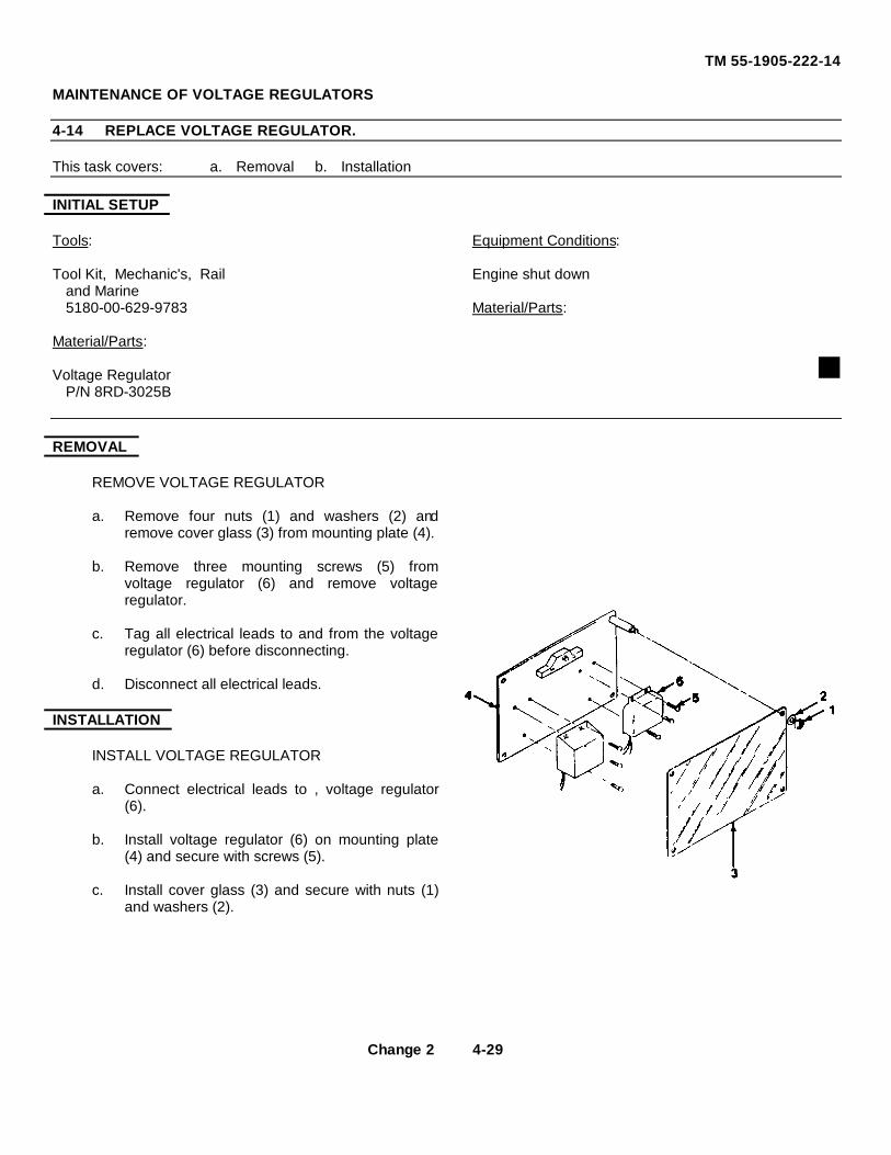
TM 55-1905-222-14
MAINTENANCE OF VOLTAGE REGULATORS
4-14 REPLACE VOLTAGE REGULATOR.
This task covers: a. Removal b. Installation
INITIAL SETUP
Tools: Equipment Conditions:
Tool Kit, Mechanic's, Rail Engine shut downand Marine5180-00-629-9783 Material/Parts:
Material/Parts:
Voltage RegulatorP/N 8RD-3025B
REMOVAL
REMOVE VOLTAGE REGULATOR
a. Remove four nuts (1) and washers (2) andremove cover glass (3) from mounting plate (4).
b. Remove three mounting screws (5) fromvoltage regulator (6) and remove voltageregulator.
c. Tag all electrical leads to and from the voltageregulator (6) before disconnecting.
d. Disconnect all electrical leads.
INSTALLATION
INSTALL VOLTAGE REGULATOR
a. Connect electrical leads to , voltage regulator(6).
b. Install voltage regulator (6) on mounting plate(4) and secure with screws (5).
c. Install cover glass (3) and secure with nuts (1)and washers (2).
Change 2 4-29
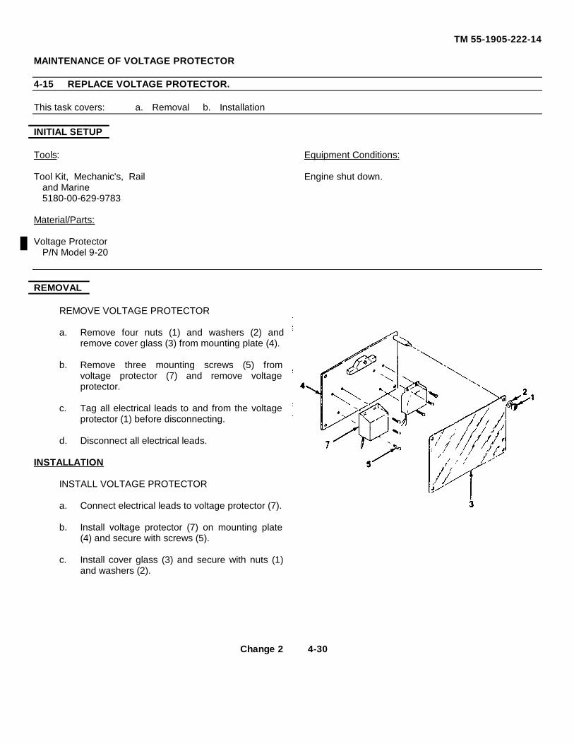
TM 55-1905-222-14
MAINTENANCE OF VOLTAGE PROTECTOR
4-15 REPLACE VOLTAGE PROTECTOR.
This task covers: a. Removal b. Installation
INITIAL SETUP
Tools: Equipment Conditions:
Tool Kit, Mechanic's, Rail Engine shut down.and Marine5180-00-629-9783
Material/Parts:
Voltage ProtectorP/N Model 9-20
REMOVAL
REMOVE VOLTAGE PROTECTOR
a. Remove four nuts (1) and washers (2) andremove cover glass (3) from mounting plate (4).
b. Remove three mounting screws (5) fromvoltage protector (7) and remove voltageprotector.
c. Tag all electrical leads to and from the voltageprotector (1) before disconnecting.
d. Disconnect all electrical leads.
INSTALLATION
INSTALL VOLTAGE PROTECTOR
a. Connect electrical leads to voltage protector (7).
b. Install voltage protector (7) on mounting plate(4) and secure with screws (5).
c. Install cover glass (3) and secure with nuts (1)and washers (2).
Change 2 4-30
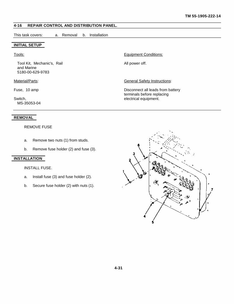
TM 55-1905-222-14
4-16 REPAIR CONTROL AND DISTRIBUTION PANEL.
This task covers: a. Removal b. Installation
INITIAL SETUP
Tools: Equipment Conditions:
Tool Kit, Mechanic's, Rail All power off.and Marine5180-00-629-9783
Material/Parts: General Safety Instructions:
Fuse, 10 amp Disconnect all leads from batteryterminals before replacing
Switch, electrical equipment.MS-35053-04
REMOVAL
REMOVE FUSE
a. Remove two nuts (1) from studs.
b. Remove fuse holder (2) and fuse (3).
INSTALLATION
INSTALL FUSE.
a. Install fuse (3) and fuse holder (2).
b. Secure fuse holder (2) with nuts (1).
4-31
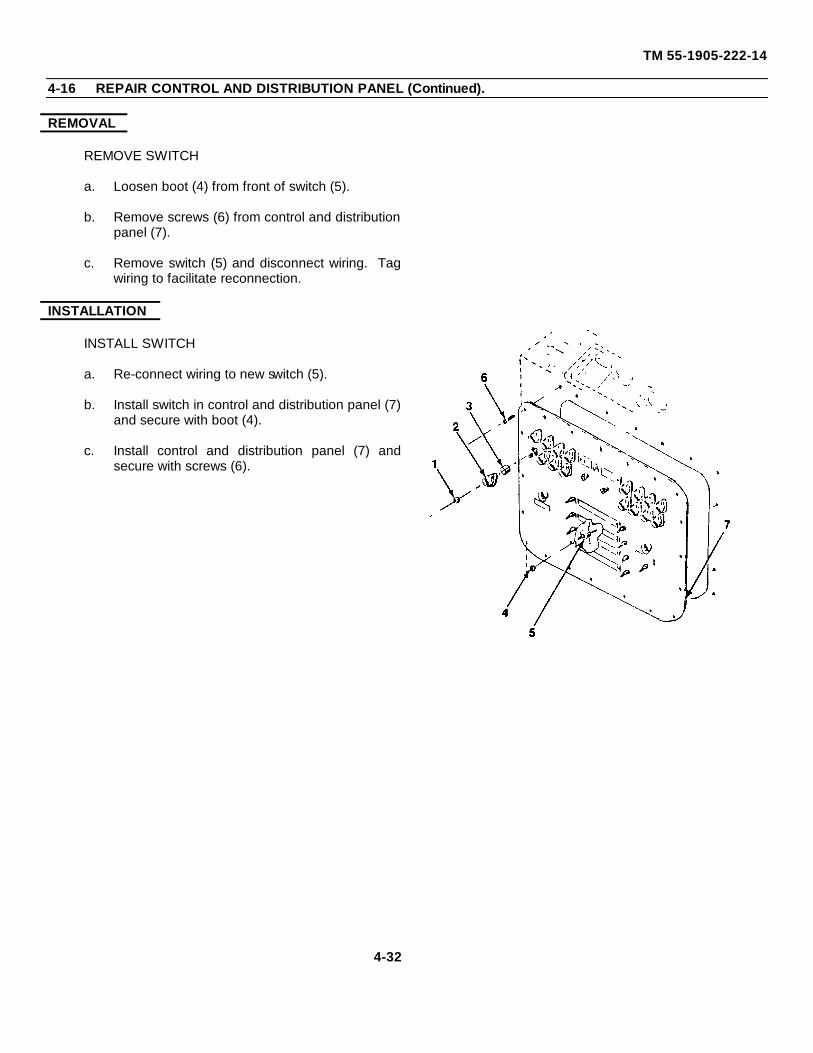
TM 55-1905-222-14
4-16 REPAIR CONTROL AND DISTRIBUTION PANEL (Continued).
REMOVAL
REMOVE SWITCH
a. Loosen boot (4) from front of switch (5).
b. Remove screws (6) from control and distributionpanel (7).
c. Remove switch (5) and disconnect wiring. Tagwiring to facilitate reconnection.
INSTALLATION
INSTALL SWITCH
a. Re-connect wiring to new switch (5).
b. Install switch in control and distribution panel (7)and secure with boot (4).
c. Install control and distribution panel (7) andsecure with screws (6).
4-32
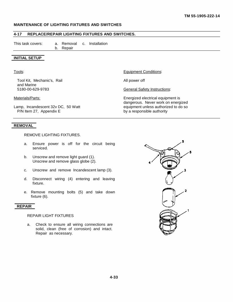
TM 55-1905-222-14
MAINTENANCE OF LIGHTING FIXTURES AND SWITCHES
4-17 REPLACE/REPAIR LIGHTING FIXTURES AND SWITCHES.
This task covers: a. Removal c. Installationb. Repair
INITIAL SETUP
Tools: Equipment Conditions:
Tool Kit, Mechanic's, Rail All power offand Marine5180-00-629-9783 General Safety Instructions:
Materials/Parts: Energized electrical equipment isdangerous. Never work on energized
Lamp, Incandescent 32v DC, 50 Watt equipment unless authorized to do soP/N Item 27, Appendix E by a responsible authority
REMOVAL
REMOVE LIGHTING FIXTURES.
a. Ensure power is off for the circuit beingserviced.
b. Unscrew and remove light guard (1).Unscrew and remove glass globe (2).
c. Unscrew and remove Incandescent lamp (3).
d. Disconnect wiring (4) entering and leavingfixture.
e. Remove mounting bolts (5) and take downfixture (6).
REPAIR
REPAIR LIGHT FIXTURES
a. Check to ensure all wiring connections aresolid, clean (free of corrosion) and intact.Repair as necessary.
4-33
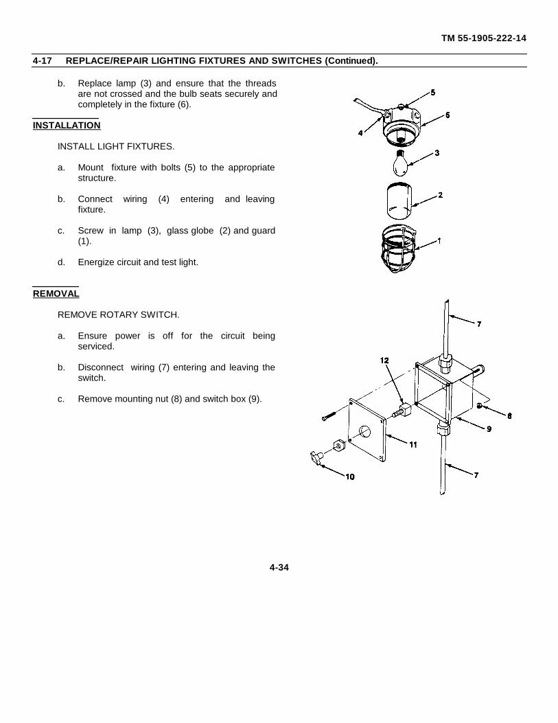
TM 55-1905-222-14
4-17 REPLACE/REPAIR LIGHTING FIXTURES AND SWITCHES (Continued).
b. Replace lamp (3) and ensure that the threadsare not crossed and the bulb seats securely andcompletely in the fixture (6).
INSTALLATION
INSTALL LIGHT FIXTURES.
a. Mount fixture with bolts (5) to the appropriatestructure.
b. Connect wiring (4) entering and leavingfixture.
c. Screw in lamp (3), glass globe (2) and guard(1).
d. Energize circuit and test light.
REMOVAL
REMOVE ROTARY SWITCH.
a. Ensure power is off for the circuit beingserviced.
b. Disconnect wiring (7) entering and leaving theswitch.
c. Remove mounting nut (8) and switch box (9).
4-34
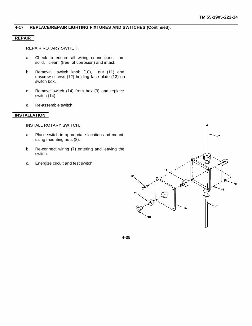
TM 55-1905-222-14
4-17 REPLACE/REPAIR LIGHTING FIXTURES AND SWITCHES (Continued).
REPAIR
REPAIR ROTARY SWITCH.
a. Check to ensure all wiring connections aresolid, clean (free of corrosion) and intact.
b. Remove switch knob (10), nut (11) andunscrew screws (12) holding face plate (13) onswitch box.
c. Remove switch (14) from box (9) and replaceswitch (14).
d. Re-assemble switch.
INSTALLATION
INSTALL ROTARY SWITCH.
a. Place switch in appropriate location and mount,using mounting nuts (8).
b. Re-connect wiring (7) entering and leaving theswitch.
c. Energize circuit and test switch.
4-35
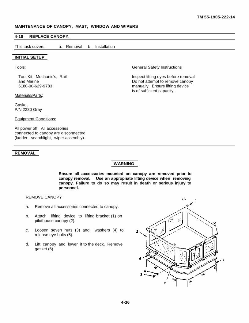
TM 55-1905-222-14
MAINTENANCE OF CANOPY, MAST, WINDOW AND WIPERS
4-18 REPLACE CANOPY.
This task covers: a. Removal b. Installation
INITIAL SETUP
Tools: General Safety Instructions:
Tool Kit, Mechanic's, Rail Inspect lifting eyes before removaland Marine Do not attempt to remove canopy5180-00-629-9783 manually. Ensure lifting device
is of sufficient capacity.Materials/Parts:
GasketP/N 2230 Gray
Equipment Conditions:
All power off. All accessoriesconnected to canopy are disconnected(ladder, searchlight, wiper assembly).
REMOVAL
WARNING
Ensure all accessories mounted on canopy are removed prior tocanopy removal. Use an appropriate lifting device when removingcanopy. Failure to do so may result in death or serious injury topersonnel.
REMOVE CANOPY
a. Remove all accessories connected to canopy.
b. Attach lifting device to lifting bracket (1) onpilothouse canopy (2).
c. Loosen seven nuts (3) and washers (4) torelease eye bolts (5).
d. Lift canopy and lower it to the deck. Removegasket (6).
4-36

TM 55-1905-222-14
4-18 REPLACE CANOPY (Continued).
INSTALLATION
INSTALL CANOPY.
a. Install new gasket (6).
b. Lift canopy and place. it on the pilothousebase (7).
c. Check gasket for proper alignment.
d. Secure canopy with eyebolts (5), washers(4), and nuts (3). Torque nuts to 71-75 foot-pounds (96 26- 101 69 nm).
e. Re-attach accessories to canopy.
4-37
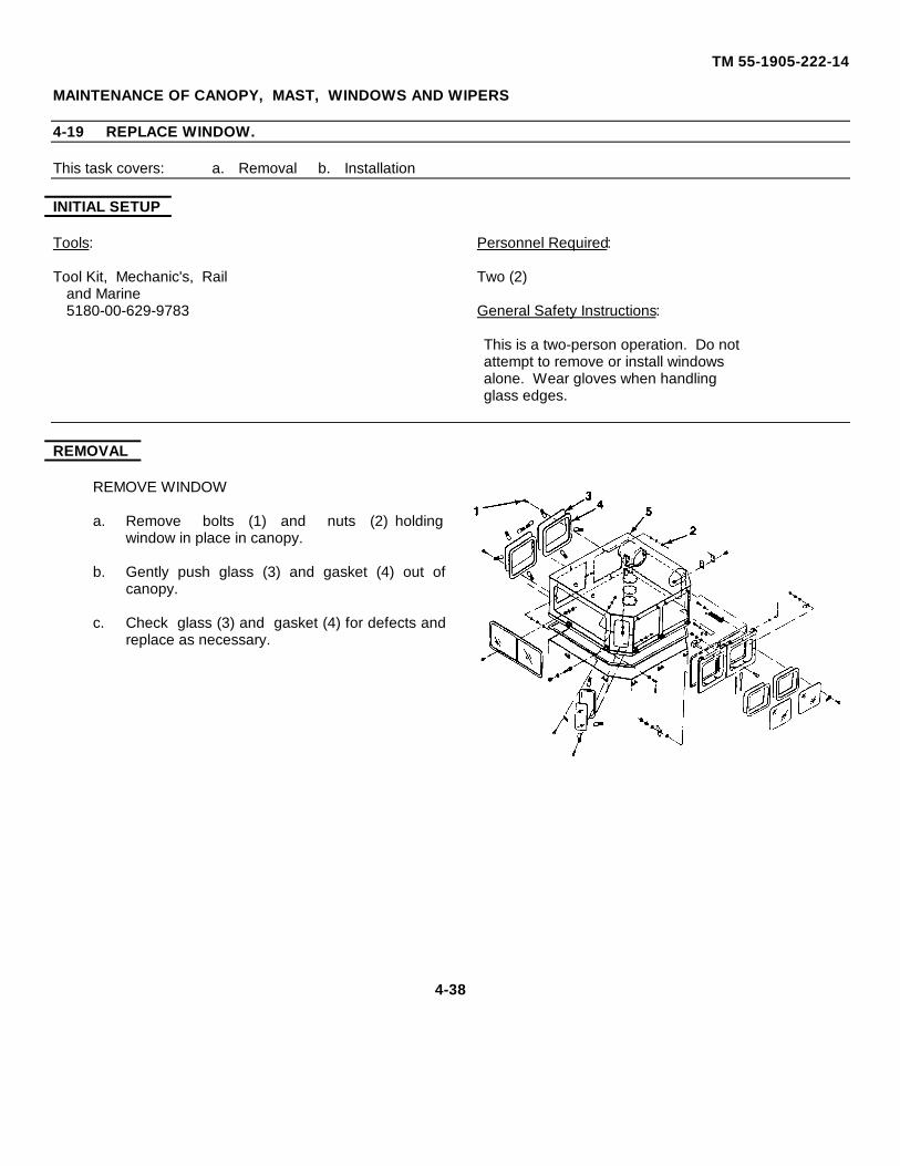
TM 55-1905-222-14
MAINTENANCE OF CANOPY, MAST, WINDOWS AND WIPERS
4-19 REPLACE WINDOW.
This task covers: a. Removal b. Installation
INITIAL SETUP
Tools: Personnel Required:
Tool Kit, Mechanic's, Rail Two (2)and Marine5180-00-629-9783 General Safety Instructions:
This is a two-person operation. Do notattempt to remove or install windowsalone. Wear gloves when handlingglass edges.
REMOVAL
REMOVE WINDOW
a. Remove bolts (1) and nuts (2) holdingwindow in place in canopy.
b. Gently push glass (3) and gasket (4) out ofcanopy.
c. Check glass (3) and gasket (4) for defects andreplace as necessary.
4-38
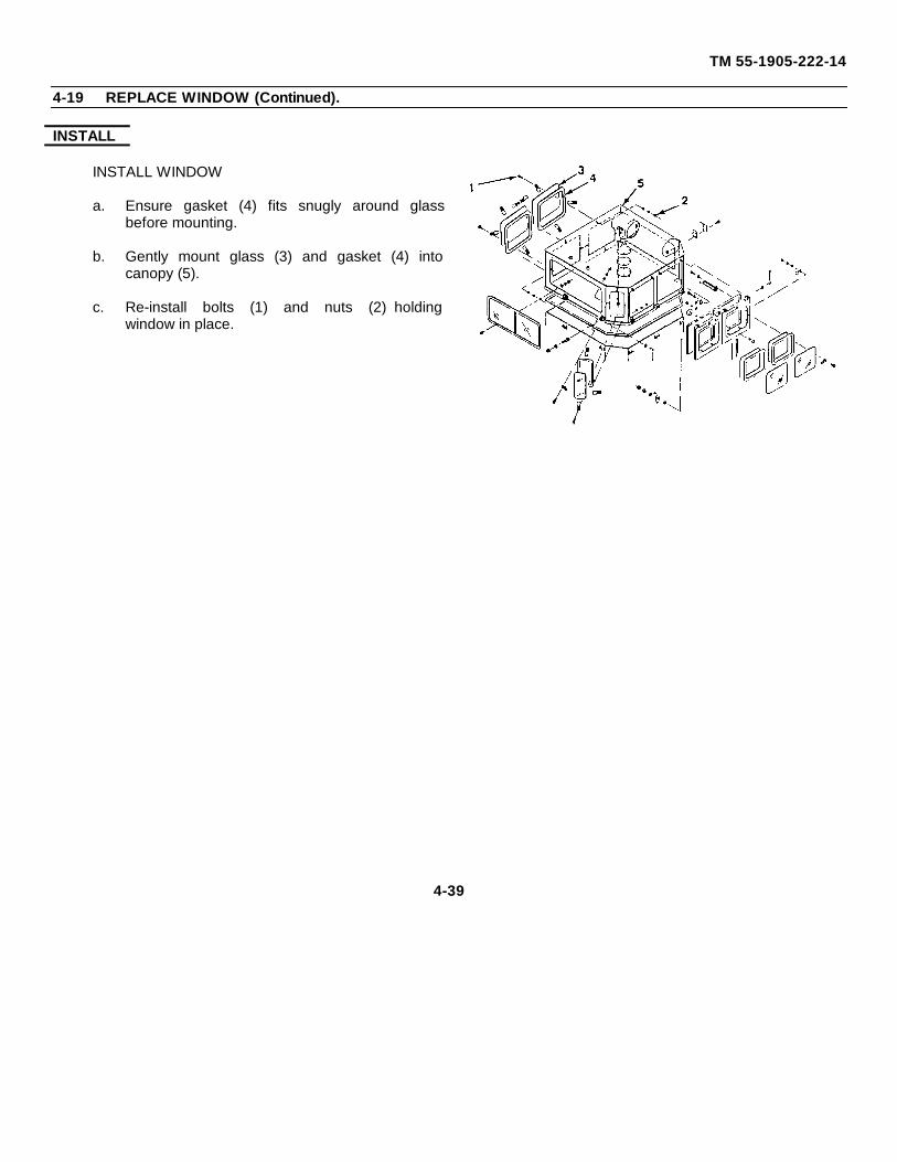
TM 55-1905-222-14
4-19 REPLACE WINDOW (Continued).
INSTALL
INSTALL WINDOW
a. Ensure gasket (4) fits snugly around glassbefore mounting.
b. Gently mount glass (3) and gasket (4) intocanopy (5).
c. Re-install bolts (1) and nuts (2) holdingwindow in place.
4-39
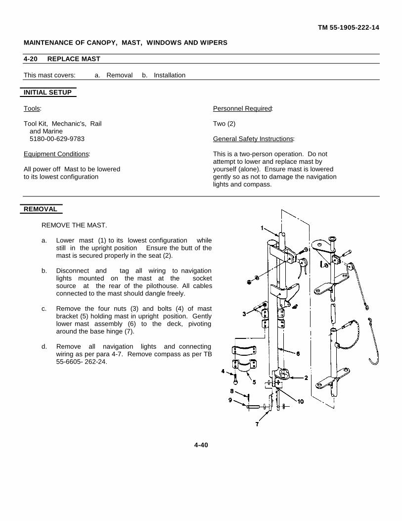
TM 55-1905-222-14
MAINTENANCE OF CANOPY, MAST, WINDOWS AND WIPERS
4-20 REPLACE MAST
This mast covers: a. Removal b. Installation
INITIAL SETUP
Tools: Personnel Required:
Tool Kit, Mechanic's, Rail Two (2)and Marine5180-00-629-9783 General Safety Instructions:
Equipment Conditions: This is a two-person operation. Do notattempt to lower and replace mast by
All power off Mast to be lowered yourself (alone). Ensure mast is loweredto its lowest configuration gently so as not to damage the navigation
lights and compass.
REMOVAL
REMOVE THE MAST.
a. Lower mast (1) to its lowest configuration whilestill in the upright position Ensure the butt of themast is secured properly in the seat (2).
b. Disconnect and tag all wiring to navigationlights mounted on the mast at the socketsource at the rear of the pilothouse. All cablesconnected to the mast should dangle freely.
c. Remove the four nuts (3) and bolts (4) of mastbracket (5) holding mast in upright position. Gentlylower mast assembly (6) to the deck, pivotingaround the base hinge (7).
d. Remove all navigation lights and connectingwiring as per para 4-7. Remove compass as per TB55-6605- 262-24.
4-40
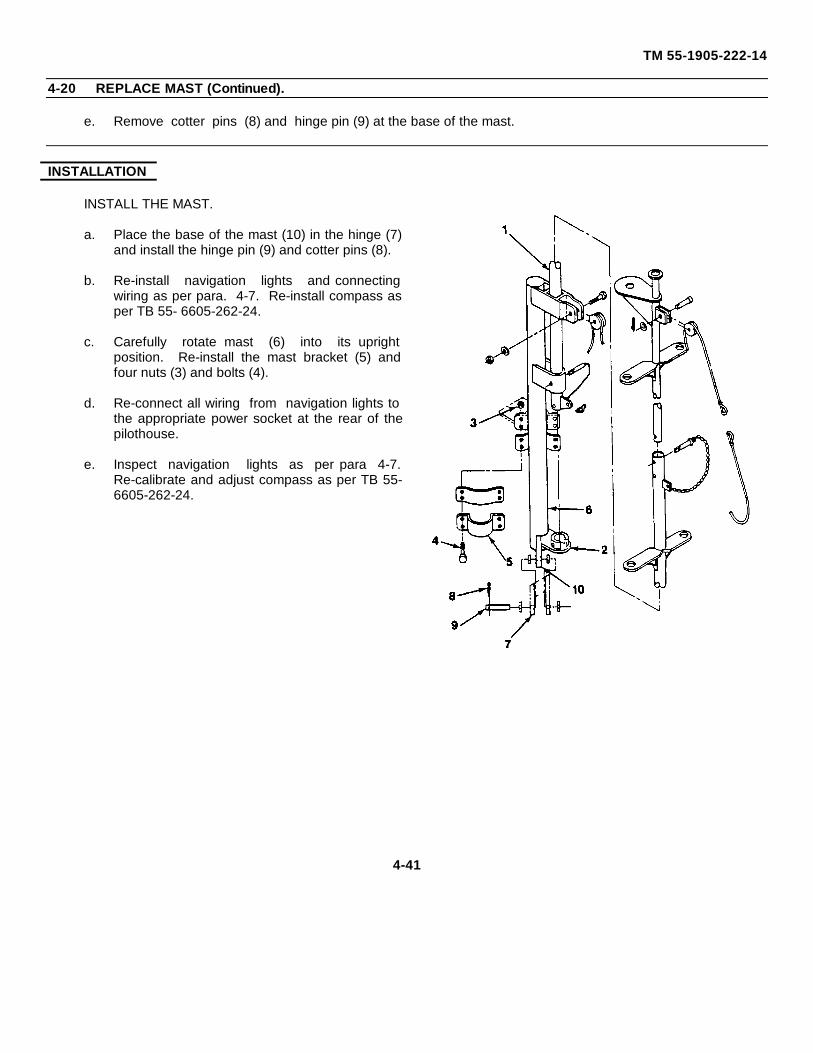
TM 55-1905-222-14
4-20 REPLACE MAST (Continued).
e. Remove cotter pins (8) and hinge pin (9) at the base of the mast.
INSTALLATION
INSTALL THE MAST.
a. Place the base of the mast (10) in the hinge (7)and install the hinge pin (9) and cotter pins (8).
b. Re-install navigation lights and connectingwiring as per para. 4-7. Re-install compass asper TB 55- 6605-262-24.
c. Carefully rotate mast (6) into its uprightposition. Re-install the mast bracket (5) andfour nuts (3) and bolts (4).
d. Re-connect all wiring from navigation lights tothe appropriate power socket at the rear of thepilothouse.
e. Inspect navigation lights as per para 4-7.Re-calibrate and adjust compass as per TB 55-6605-262-24.
4-41
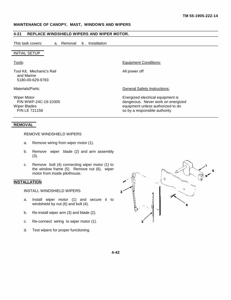
TM 55-1905-222-14
MAINTENANCE OF CANOPY, MAST, WINDOWS AND WIPERS
4-21 REPLACE WINDSHIELD WIPERS AND WIPER MOTOR.
This task covers: a. Removal b . Installation
INITIAL SETUP
Tools: Equipment Conditions:
Tool Kit, Mechanic's Rail All power offand Marine5180-00-629-9783
Materials/Parts: General Safety Instructions:
Wiper Motor Energized electrical equipment isP/N WWF-24C-19-10305 dangerous. Never work on energized
Wiper Blades equipment unless authorized to doP/N LE 721156 so by a responsible authority
REMOVAL
REMOVE WINDSHIELD WIPERS
a. Remove wiring from wiper motor (1).
b. Remove wiper blade (2) and arm assembly(3).
c. Remove bolt (4) connecting wiper motor (1) tothe window frame (5). Remove nut (6), wipermotor from inside pilothouse.
INSTALLATION
INSTALL WINDSHIELD WIPERS
a. Install wiper motor (1) and secure it towindshield by nut (6) and bolt (4).
b. Re-install wiper arm (3) and blade (2).
c. Re-connect wiring to wiper motor (1).
d. Test wipers for proper functioning.
4-42
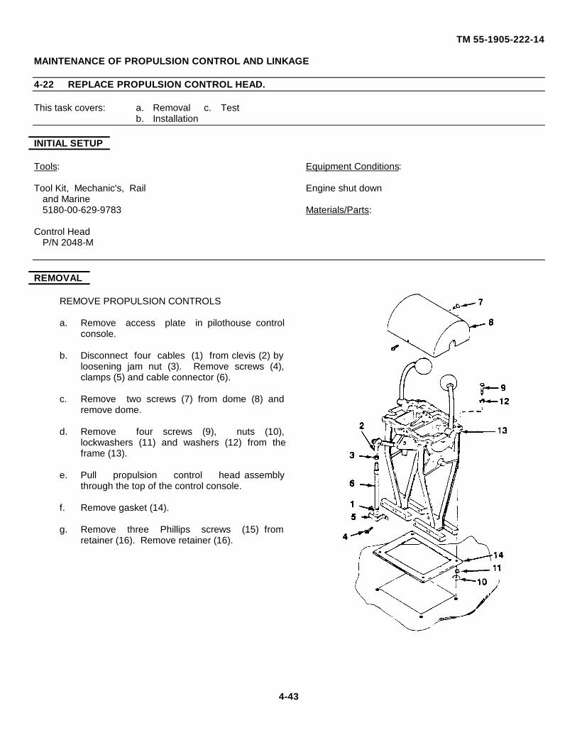
TM 55-1905-222-14
MAINTENANCE OF PROPULSION CONTROL AND LINKAGE
4-22 REPLACE PROPULSION CONTROL HEAD.
This task covers: a. Removal c. Testb. Installation
INITIAL SETUP
Tools: Equipment Conditions:
Tool Kit, Mechanic's, Rail Engine shut downand Marine5180-00-629-9783 Materials/Parts:
Control HeadP/N 2048-M
REMOVAL
REMOVE PROPULSION CONTROLS
a. Remove access plate in pilothouse controlconsole.
b. Disconnect four cables (1) from clevis (2) byloosening jam nut (3). Remove screws (4),clamps (5) and cable connector (6).
c. Remove two screws (7) from dome (8) andremove dome.
d. Remove four screws (9), nuts (10),lockwashers (11) and washers (12) from theframe (13).
e. Pull propulsion control head assemblythrough the top of the control console.
f. Remove gasket (14).
g. Remove three Phillips screws (15) fromretainer (16). Remove retainer (16).
4-43
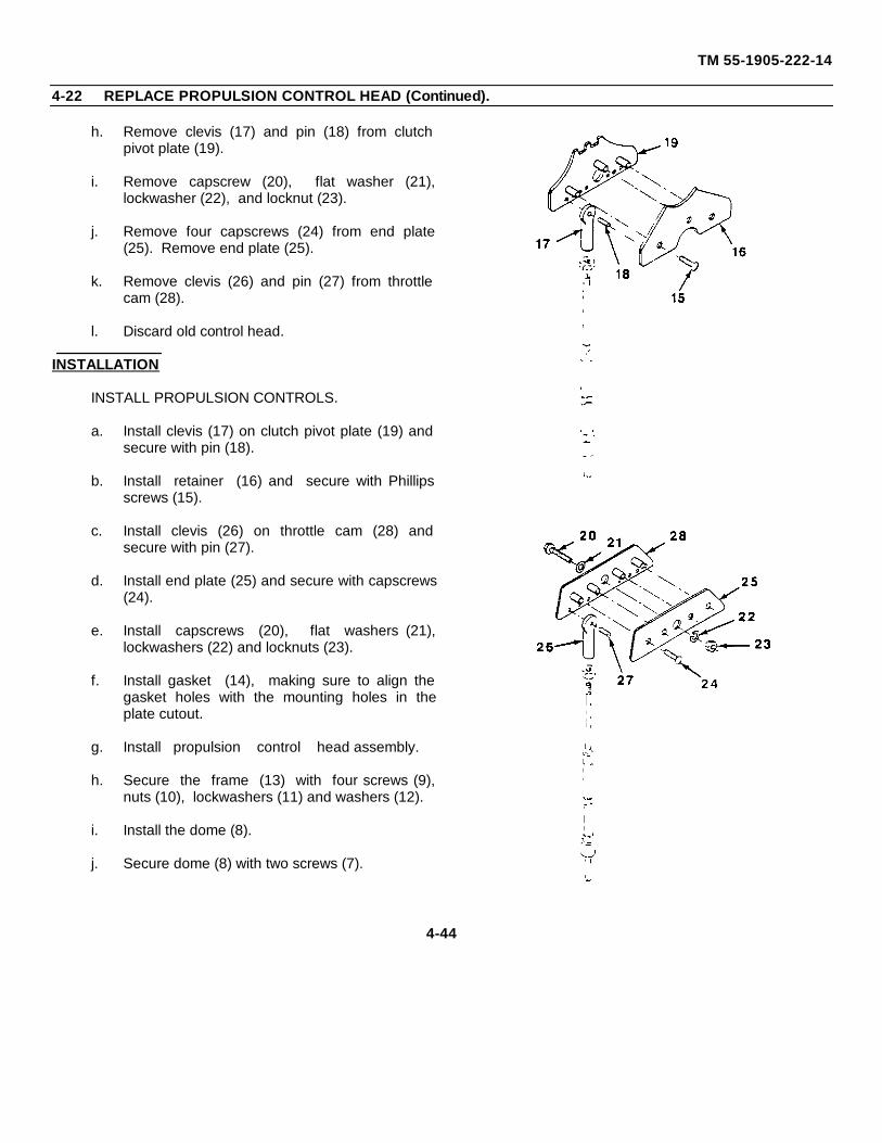
TM 55-1905-222-14
4-22 REPLACE PROPULSION CONTROL HEAD (Continued).
h. Remove clevis (17) and pin (18) from clutchpivot plate (19).
i. Remove capscrew (20), flat washer (21),lockwasher (22), and locknut (23).
j. Remove four capscrews (24) from end plate(25). Remove end plate (25).
k. Remove clevis (26) and pin (27) from throttlecam (28).
l. Discard old control head.
INSTALLATION
INSTALL PROPULSION CONTROLS.
a. Install clevis (17) on clutch pivot plate (19) andsecure with pin (18).
b. Install retainer (16) and secure with Phillipsscrews (15).
c. Install clevis (26) on throttle cam (28) andsecure with pin (27).
d. Install end plate (25) and secure with capscrews(24).
e. Install capscrews (20), flat washers (21),lockwashers (22) and locknuts (23).
f. Install gasket (14), making sure to align thegasket holes with the mounting holes in theplate cutout.
g. Install propulsion control head assembly.
h. Secure the frame (13) with four screws (9),nuts (10), lockwashers (11) and washers (12).
i. Install the dome (8).
j. Secure dome (8) with two screws (7).
4-44
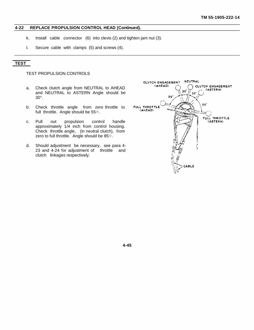
TM 55-1905-222-14
4-22 REPLACE PROPULSION CONTROL HEAD (Continued).
k. Install cable connector (6) into clevis (2) and tighten jam nut (3).
I. Secure cable with clamps (5) and screws (4).
TEST
TEST PROPULSION CONTROLS
a. Check clutch angle from NEUTRAL to AHEADand NEUTRAL to ASTERN Angle should be30°.
b. Check throttle angle from zero throttle tofull throttle. Angle should be 55.
c. Pull out propulsion control handleapproximately 1/4 inch from control housing.Check throttle angle, (in neutral clutch), fromzero to full throttle. Angle should be 85.
d. Should adjustment be necessary, see para 4-23 and 4-24 for adjustment of throttle andclutch linkages respectively.
4-45
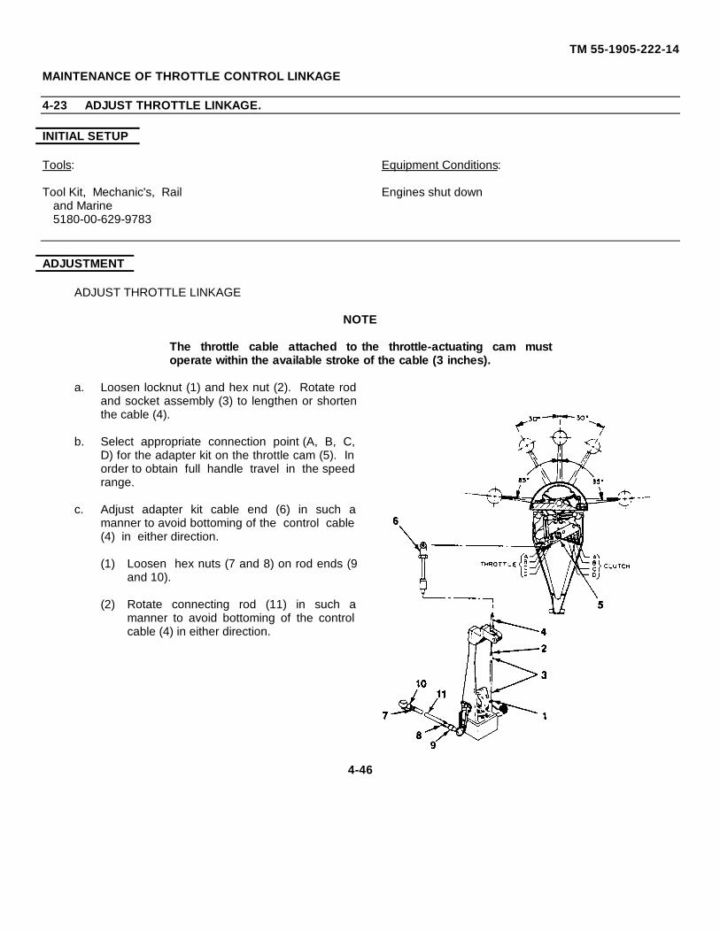
TM 55-1905-222-14
MAINTENANCE OF THROTTLE CONTROL LINKAGE
4-23 ADJUST THROTTLE LINKAGE.
INITIAL SETUP
Tools: Equipment Conditions:
Tool Kit, Mechanic's, Rail Engines shut downand Marine5180-00-629-9783
ADJUSTMENT
ADJUST THROTTLE LINKAGE
NOTE
The throttle cable attached to the throttle-actuating cam mustoperate within the available stroke of the cable (3 inches).
a. Loosen locknut (1) and hex nut (2). Rotate rodand socket assembly (3) to lengthen or shortenthe cable (4).
b. Select appropriate connection point (A, B, C,D) for the adapter kit on the throttle cam (5). Inorder to obtain full handle travel in the speedrange.
c. Adjust adapter kit cable end (6) in such amanner to avoid bottoming of the control cable(4) in either direction.
(1) Loosen hex nuts (7 and 8) on rod ends (9and 10).
(2) Rotate connecting rod (11) in such amanner to avoid bottoming of the controlcable (4) in either direction.
4-46
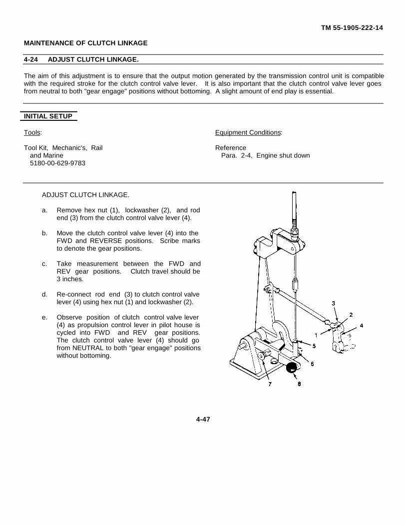
TM 55-1905-222-14
MAINTENANCE OF CLUTCH LINKAGE
4-24 ADJUST CLUTCH LINKAGE.
The aim of this adjustment is to ensure that the output motion generated by the transmission control unit is compatiblewith the required stroke for the clutch control valve lever. It is also important that the clutch control valve lever goesfrom neutral to both "gear engage" positions without bottoming. A slight amount of end play is essential.
INITIAL SETUP
Tools: Equipment Conditions:
Tool Kit, Mechanic's, Rail Referenceand Marine Para. 2-4, Engine shut down5180-00-629-9783
ADJUST CLUTCH LINKAGE.
a. Remove hex nut (1), lockwasher (2), and rodend (3) from the clutch control valve lever (4).
b. Move the clutch control valve lever (4) into theFWD and REVERSE positions. Scribe marksto denote the gear positions.
c. Take measurement between the FWD andREV gear positions. Clutch travel should be3 inches.
d. Re-connect rod end (3) to clutch control valvelever (4) using hex nut (1) and lockwasher (2).
e. Observe position of clutch control valve lever(4) as propulsion control lever in pilot house iscycled into FWD and REV gear positions.The clutch control valve lever (4) should gofrom NEUTRAL to both "gear engage" positionswithout bottoming.
4-47
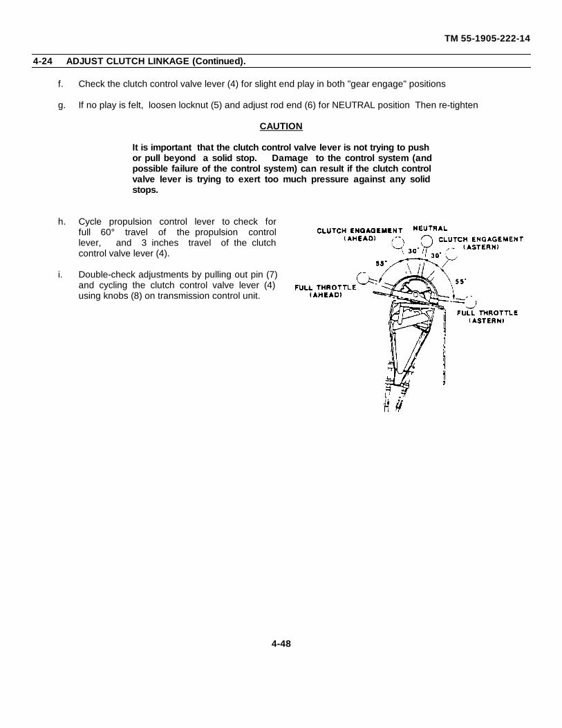
TM 55-1905-222-14
4-24 ADJUST CLUTCH LINKAGE (Continued).
f. Check the clutch control valve lever (4) for slight end play in both "gear engage" positions
g. If no play is felt, loosen locknut (5) and adjust rod end (6) for NEUTRAL position Then re-tighten
CAUTION
It is important that the clutch control valve lever is not trying to pushor pull beyond a solid stop. Damage to the control system (andpossible failure of the control system) can result if the clutch controlvalve lever is trying to exert too much pressure against any solidstops.
h. Cycle propulsion control lever to check forfull 60° travel of the propulsion controllever, and 3 inches travel of the clutchcontrol valve lever (4).
i. Double-check adjustments by pulling out pin (7)and cycling the clutch control valve lever (4)using knobs (8) on transmission control unit.
4-48

TM 55-1905-222-14
4-24 ADJUST CLUTCH LINKAGE (Continued).
CAUTION
Do not use thread-locking adhesive or self-locking nuts on cablethreads, or damage to the cable may result.
j. After all adjustments are made, apply a heat-resistant crease to all ball joint sockets, and alight film on all rod ends (3 and 6).
k. Double-check fasteners for tightness, but donot overtighten.
4-49
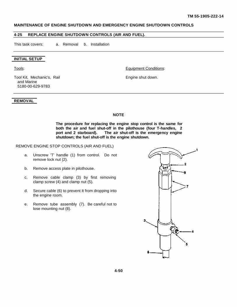
TM 55-1905-222-14
MAINTENANCE OF ENGINE SHUTDOWN AND EMERGENCY ENGINE SHUTDOWN CONTROLS
4-25 REPLACE ENGINE SHUTDOWN CONTROLS (AIR AND FUEL).
This task covers: a. Removal b. Installation
INITIAL SETUP
Tools: Equipment Conditions:
Tool Kit, Mechanic's, Rail Engine shut down.and Marine5180-00-629-9783
REMOVAL
NOTE
The procedure for replacing the engine stop control is the same forboth the air and fuel shut-off in the pilothouse (four T-handles, 2port and 2 starboard). The air shut-off is the emergency engineshutdown; the fuel shut-off is the engine shutdown.
REMOVE ENGINE STOP CONTROLS (AIR AND FUEL)
a. Unscrew 'T' handle (1) from control. Do notremove lock nut (2).
b. Remove access plate in pilothouse.
c. Remove cable clamp (3) by first removingclamp screw (4) and clamp nut (5).
d. Secure cable (6) to prevent It from dropping intothe engine room.
e. Remove tube assembly (7). Be careful not tolose mounting nut (8).
4-50
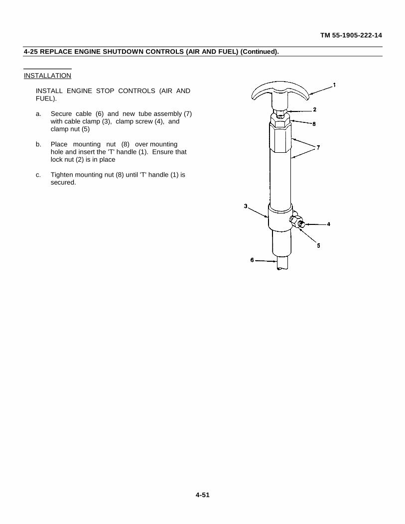
TM 55-1905-222-14
4-25 REPLACE ENGINE SHUTDOWN CONTROLS (AIR AND FUEL) (Continued).
INSTALLATION
INSTALL ENGINE STOP CONTROLS (AIR ANDFUEL).
a. Secure cable (6) and new tube assembly (7)with cable clamp (3), clamp screw (4), and clamp nut (5)
b. Place mounting nut (8) over mounting hole and insert the 'T' handle (1). Ensure that lock nut (2) is in place
c. Tighten mounting nut (8) until 'T' handle (1) is secured.
4-51
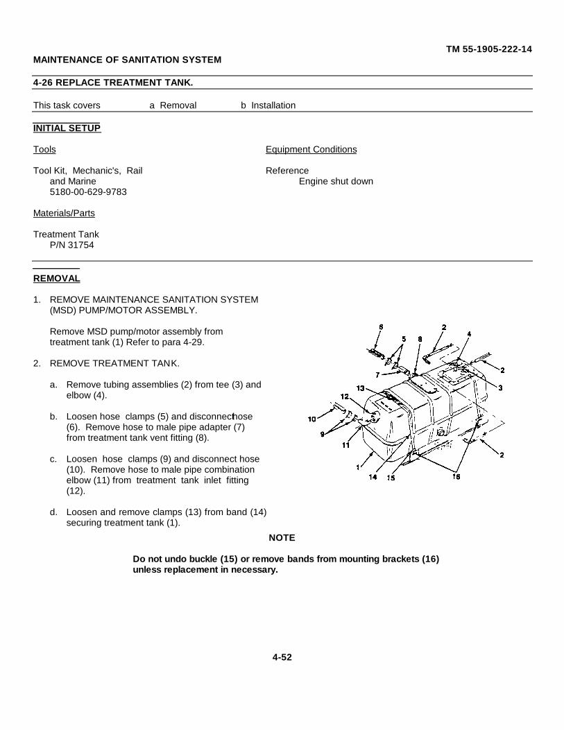
TM 55-1905-222-14MAINTENANCE OF SANITATION SYSTEM
4-26 REPLACE TREATMENT TANK.
This task covers a Removal b Installation
INITIAL SETUP
Tools Equipment Conditions
Tool Kit, Mechanic's, Rail Referenceand Marine Engine shut down5180-00-629-9783
Materials/Parts
Treatment TankP/N 31754
REMOVAL
1. REMOVE MAINTENANCE SANITATION SYSTEM (MSD) PUMP/MOTOR ASSEMBLY.
Remove MSD pump/motor assembly from treatment tank (1) Refer to para 4-29.
2. REMOVE TREATMENT TANK.
a. Remove tubing assemblies (2) from tee (3) and elbow (4).
b. Loosen hose clamps (5) and disconnecthose (6). Remove hose to male pipe adapter (7) from treatment tank vent fitting (8).
c. Loosen hose clamps (9) and disconnect hose (10). Remove hose to male pipe combination elbow (11) from treatment tank inlet fitting (12).
d. Loosen and remove clamps (13) from band (14)securing treatment tank (1).
NOTE
Do not undo buckle (15) or remove bands from mounting brackets (16)unless replacement in necessary.
4-52
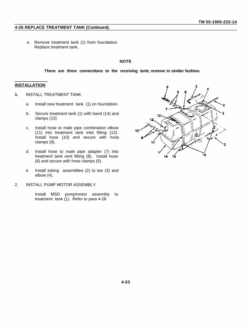
TM 55-1905-222-144-26 REPLACE TREATMENT TANK (Continued).
e. Remove treatment tank (1) from foundation.Replace treatment tank.
NOTE
There are three connections to the receiving tank; remove in similar fashion.
INSTALLATION
1. INSTALL TREATMENT TANK.
a. Install new treatment tank (1) on foundation.
b. Secure treatment tank (1) with band (14) andclamps (13)
c. Install hose to male pipe combination elbow(11) into treatment tank inlet fitting (12).Install hose (10) and secure with hoseclamps (9).
d. Install hose to male pipe adapter (7) intotreatment tank vent fitting (8). Install hose(6) and secure with hose clamps (5).
e. Install tubing assemblies (2) to tee (3) andelbow (4).
2. INSTALL PUMP MOTOR ASSEMBLY.
Install MSD pump/motor assembly totreatment tank (1). Refer to para 4-28
4-53
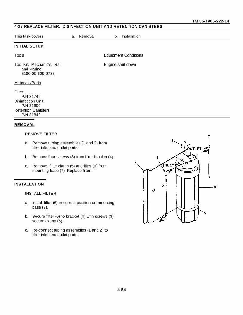
TM 55-1905-222-144-27 REPLACE FILTER, DISINFECTION UNIT AND RETENTION CANISTERS.
This task covers a. Removal b. Installation
INITIAL SETUP
Tools Equipment Conditions
Tool Kit, Mechanic's, Rail Engine shut downand Marine5180-00-629-9783
Materials/Parts
FilterP/N 31749
Disinfection UnitP/N 31690
Retention CanistersP/N 31842
REMOVAL
REMOVE FILTER
a. Remove tubing assemblies (1 and 2) from filter inlet and outlet ports.
b. Remove four screws (3) from filter bracket (4).
c. Remove filter clamp (5) and filter (6) from mounting base (7) Replace filter.
INSTALLATION
INSTALL FILTER
a Install filter (6) in correct position on mountingbase (7).
b. Secure filter (6) to bracket (4) with screws (3),secure clamp (5).
c. Re-connect tubing assemblies (1 and 2) to filter inlet and outlet ports.
4-54
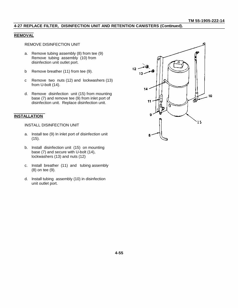
TM 55-1905-222-144-27 REPLACE FILTER, DISINFECTION UNIT AND RETENTION CANISTERS (Continued).
REMOVAL
REMOVE DISINFECTION UNIT
a. Remove tubing assembly (8) from tee (9) Remove tubing assembly (10) from disinfection unit outlet port.
b Remove breather (11) from tee (9).
c Remove two nuts (12) and lockwashers (13)from U-bolt (14).
d. Remove disinfection unit (15) from mountingbase (7) and remove tee (9) from inlet port of disinfection unit. Replace disinfection unit.
INSTALLATION
INSTALL DISINFECTION UNIT
a. Install tee (9) In inlet port of disinfection unit (15).
b. Install disinfection unit (15) on mounting base (7) and secure with U-bolt (14), lockwashers (13) and nuts (12)
c. Install breather (11) and tubing assembly (8) on tee (9).
d. Install tubing assembly (10) in disinfection unit outlet port.
4-55
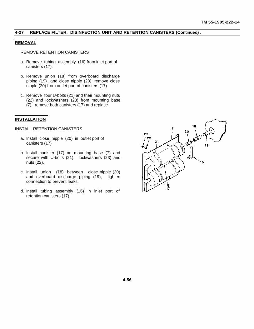
TM 55-1905-222-14
4-27 REPLACE FILTER, DISINFECTION UNIT AND RETENTION CANISTERS (Continued) .
REMOVAL
REMOVE RETENTION CANISTERS
a. Remove tubing assembly (16) from inlet port of canisters (17).
b. Remove union (18) from overboard dischargepiping (19) and close nipple (20), remove closenipple (20) from outlet port of canisters (17)
c. Remove four U-bolts (21) and their mounting nuts(22) and lockwashers (23) from mounting base(7), remove both canisters (17) and replace
INSTALLATION
INSTALL RETENTION CANISTERS
a. Install close nipple (20) in outlet port of canisters (17).
b. Install canister (17) on mounting base (7) andsecure with U-bolts (21), lockwashers (23) andnuts (22).
c. Install union (18) between close nipple (20)and overboard discharge piping (19), tightenconnection to prevent leaks.
d. Install tubing assembly (16) In inlet port ofretention canisters (17)
4-56
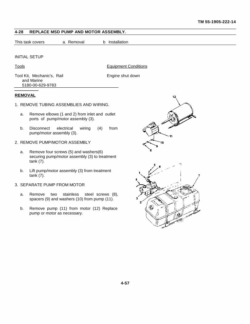
TM 55-1905-222-14
4-28 REPLACE MSD PUMP AND MOTOR ASSEMBLY.
This task covers a. Removal b Installation
INITIAL SETUP
Tools Equipment Conditions
Tool Kit, Mechanic's, Rail Engine shut downand Marine5180-00-629-9783
REMOVAL
1. REMOVE TUBING ASSEMBLIES AND WIRING.
a. Remove elbows (1 and 2) from inlet and outlet ports of pump/motor assembly (3).
b. Disconnect electrical wiring (4) frompump/motor assembly (3).
2. REMOVE PUMP/MOTOR ASSEMBLY
a. Remove four screws (5) and washers(6) securing pump/motor assembly (3) to treatment tank (7).
b. Lift pump/motor assembly (3) from treatment tank (7).
3. SEPARATE PUMP FROM MOTOR
a. Remove two stainless steel screws (8),spacers (9) and washers (10) from pump (11).
b. Remove pump (11) from motor (12) Replacepump or motor as necessary.
4-57
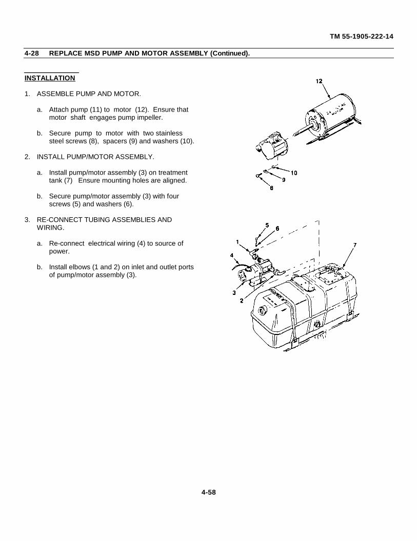
TM 55-1905-222-14
4-28 REPLACE MSD PUMP AND MOTOR ASSEMBLY (Continued).
INSTALLATION
1. ASSEMBLE PUMP AND MOTOR.
a. Attach pump (11) to motor (12). Ensure that motor shaft engages pump impeller.
b. Secure pump to motor with two stainless steel screws (8), spacers (9) and washers (10).
2. INSTALL PUMP/MOTOR ASSEMBLY.
a. Install pump/motor assembly (3) on treatment tank (7) Ensure mounting holes are aligned.
b. Secure pump/motor assembly (3) with four screws (5) and washers (6).
3. RE-CONNECT TUBING ASSEMBLIES AND WIRING.
a. Re-connect electrical wiring (4) to source of power.
b. Install elbows (1 and 2) on inlet and outlet ports of pump/motor assembly (3).
4-58
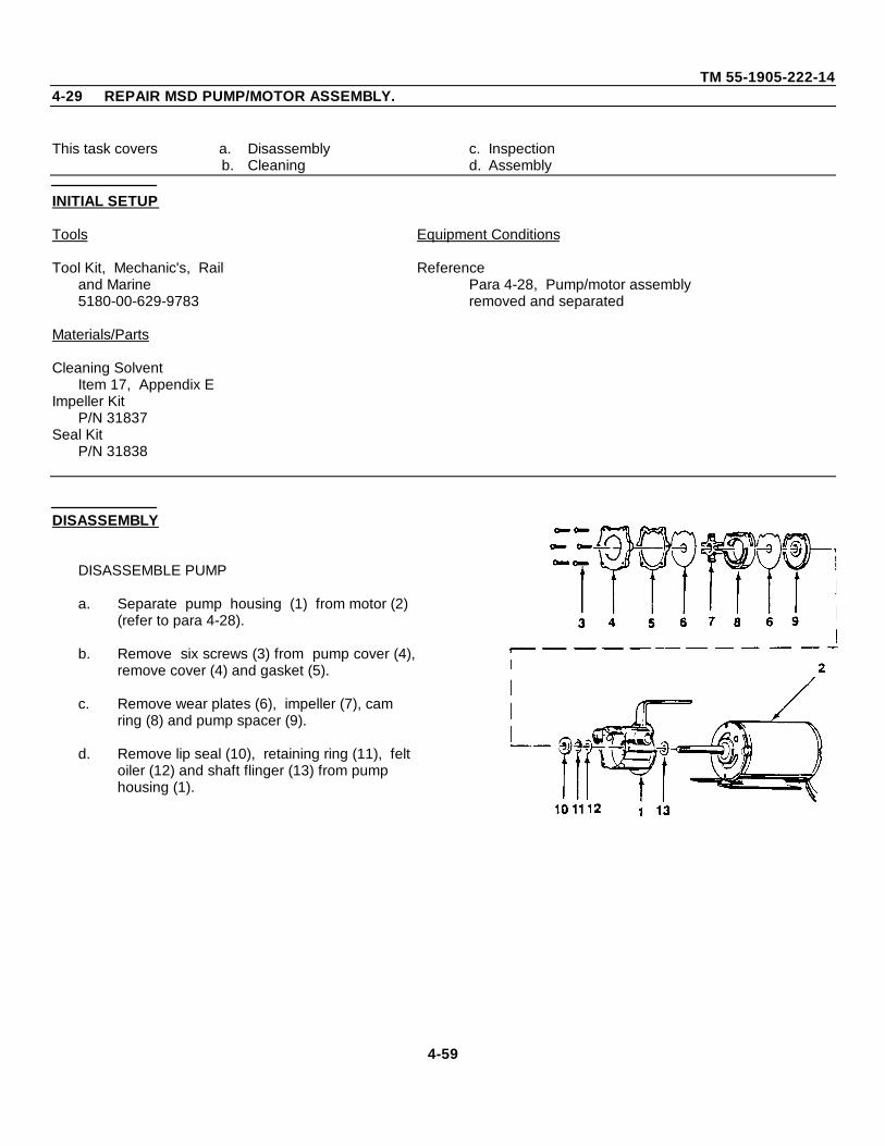
TM 55-1905-222-144-29 REPAIR MSD PUMP/MOTOR ASSEMBLY.
This task covers a. Disassembly c. Inspectionb. Cleaning d. Assembly
INITIAL SETUP
Tools Equipment Conditions
Tool Kit, Mechanic's, Rail Referenceand Marine Para 4-28, Pump/motor assembly5180-00-629-9783 removed and separated
Materials/Parts
Cleaning SolventItem 17, Appendix E
Impeller KitP/N 31837
Seal KitP/N 31838
DISASSEMBLY
DISASSEMBLE PUMP
a. Separate pump housing (1) from motor (2) (refer to para 4-28).
b. Remove six screws (3) from pump cover (4),remove cover (4) and gasket (5).
c. Remove wear plates (6), impeller (7), cam ring (8) and pump spacer (9).
d. Remove lip seal (10), retaining ring (11), felt oiler (12) and shaft flinger (13) from pump housing (1).
4-59
TM 55-1905-222-14
4-29 REPAIR MSD PUMP/MOTOR ASSEMBLY (Continued).
CLEANING
CLEAN PUMP PARTS
WARNING
Dry cleaning solvent, P-D-680, used to clean parts, is potentially dangerous topersonnel and property. Avoid repeated or prolonged skin contact. Do not use nearopen flame or excessive heat. Flash point of solvent is 100°- 138F (38 - 59C).
a. Clean all pump parts in cleaningsolvent, Fed. Spec. P-D-680.
b. Allow parts to air dry
INSPECTION
INSPECT IMPELLER, CAM RING, WEARPLATES AND SHAFT SEALS
a. Inspect impeller for wear or other damage.
b. Inspect cam ring for wear and scoring.
c. Check to see if wear plates are badly grooved or worn.
d. Inspect shaft seals (lip seal, retaining ring, felt oiler and shaft flinger) for deterioration.
e. Get replacement parts as necessary
4-60
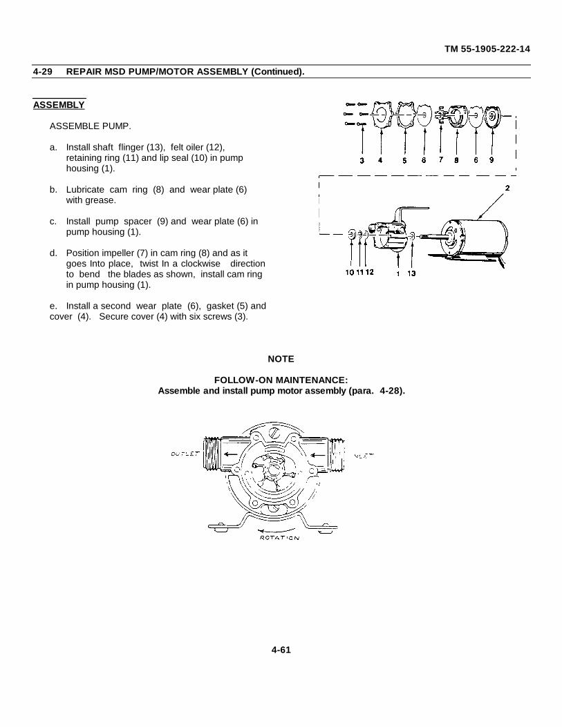
TM 55-1905-222-14
4-29 REPAIR MSD PUMP/MOTOR ASSEMBLY (Continued).
ASSEMBLY
ASSEMBLE PUMP.
a. Install shaft flinger (13), felt oiler (12), retaining ring (11) and lip seal (10) in pump housing (1).
b. Lubricate cam ring (8) and wear plate (6) with grease.
c. Install pump spacer (9) and wear plate (6) in pump housing (1).
d. Position impeller (7) in cam ring (8) and as it goes Into place, twist In a clockwise directionto bend the blades as shown, install cam ring in pump housing (1).
e. Install a second wear plate (6), gasket (5) andcover (4). Secure cover (4) with six screws (3).
NOTE
FOLLOW-ON MAINTENANCE:Assemble and install pump motor assembly (para. 4-28).
4-61
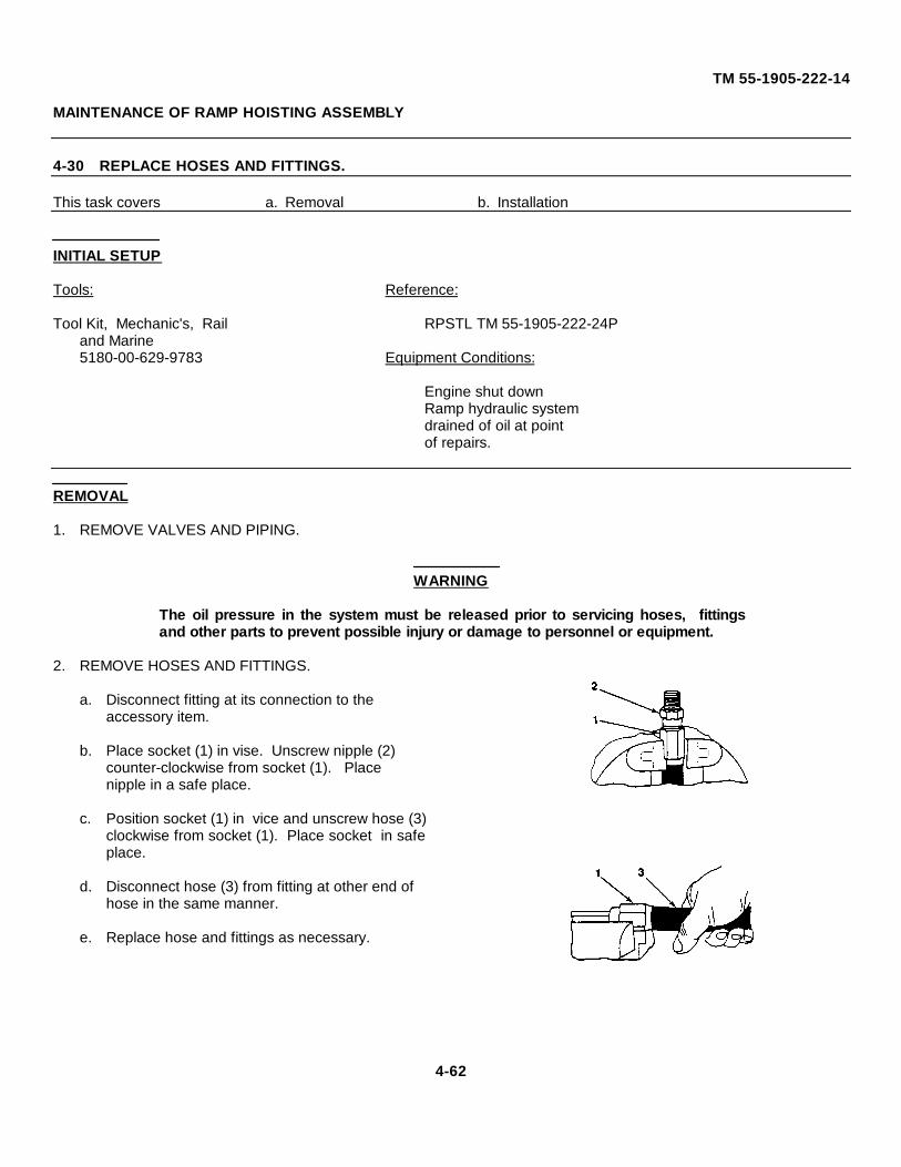
TM 55-1905-222-14
MAINTENANCE OF RAMP HOISTING ASSEMBLY
4-30 REPLACE HOSES AND FITTINGS.
This task covers a. Removal b. Installation
INITIAL SETUP
Tools: Reference:
Tool Kit, Mechanic's, Rail RPSTL TM 55-1905-222-24Pand Marine5180-00-629-9783 Equipment Conditions:
Engine shut downRamp hydraulic systemdrained of oil at pointof repairs.
REMOVAL
1. REMOVE VALVES AND PIPING.
WARNING
The oil pressure in the system must be released prior to servicing hoses, fittingsand other parts to prevent possible injury or damage to personnel or equipment.
2. REMOVE HOSES AND FITTINGS.
a. Disconnect fitting at its connection to the accessory item.
b. Place socket (1) in vise. Unscrew nipple (2) counter-clockwise from socket (1). Place nipple in a safe place.
c. Position socket (1) in vice and unscrew hose (3)clockwise from socket (1). Place socket in safeplace.
d. Disconnect hose (3) from fitting at other end of hose in the same manner.
e. Replace hose and fittings as necessary.
4-62
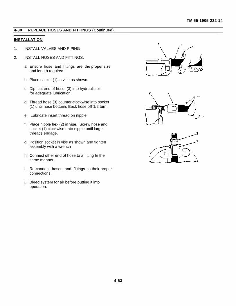
TM 55-1905-222-14
4-30 REPLACE HOSES AND FITTINGS (Continued).
INSTALLATION
1. INSTALL VALVES AND PIPING
2. INSTALL HOSES AND FITTINGS.
a. Ensure hose and fittings are the proper size and length required.
b Place socket (1) in vise as shown.
c. Dip cut end of hose (3) into hydraulic oilfor adequate lubrication.
d. Thread hose (3) counter-clockwise into socket (1) until hose bottoms Back hose off 1/2 turn.
e. Lubricate insert thread on nipple
f. Place nipple hex (2) in vise. Screw hose and socket (1) clockwise onto nipple until large threads engage.
g. Position socket in vise as shown and tighten assembly with a wrench
h. Connect other end of hose to a fitting In the same manner.
i. Re-connect hoses and fittings to their properconnections.
j. Bleed system for air before putting it into operation.
4-63
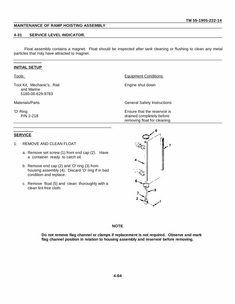
TM 55-1905-222-14MAINTENANCE OF RAMP HOISTING ASSEMBLY
4-31 SERVICE LEVEL INDICATOR.
Float assembly contains a magnet. Float should be inspected after tank cleaning or flushing to clean any metalparticles that may have attracted to magnet.
INITIAL SETUP
Tools: Equipment Conditions:
Tool Kit, Mechanic's, Rail Engine shut downand Marine5180-00-629-9783
Materials/Parts General Safety Instructions
'O' Ring Ensure that the reservoir isP/N 2-218 drained completely before
removing float for cleaning
SERVICE
1. REMOVE AND CLEAN FLOAT
a. Remove set screw (1) from end cap (2). Have a container ready to catch oil.
b. Remove end cap (2) and 'O' ring (3) from housing assembly (4). Discard 'O' ring If in bad condition and replace.
c. Remove float (5) and clean thoroughly with a clean lint-free cloth.
NOTE
Do not remove flag channel or clamps if replacement is not required. Observe and markflag channel position in relation to housing assembly and reservoir before removing.
4-64
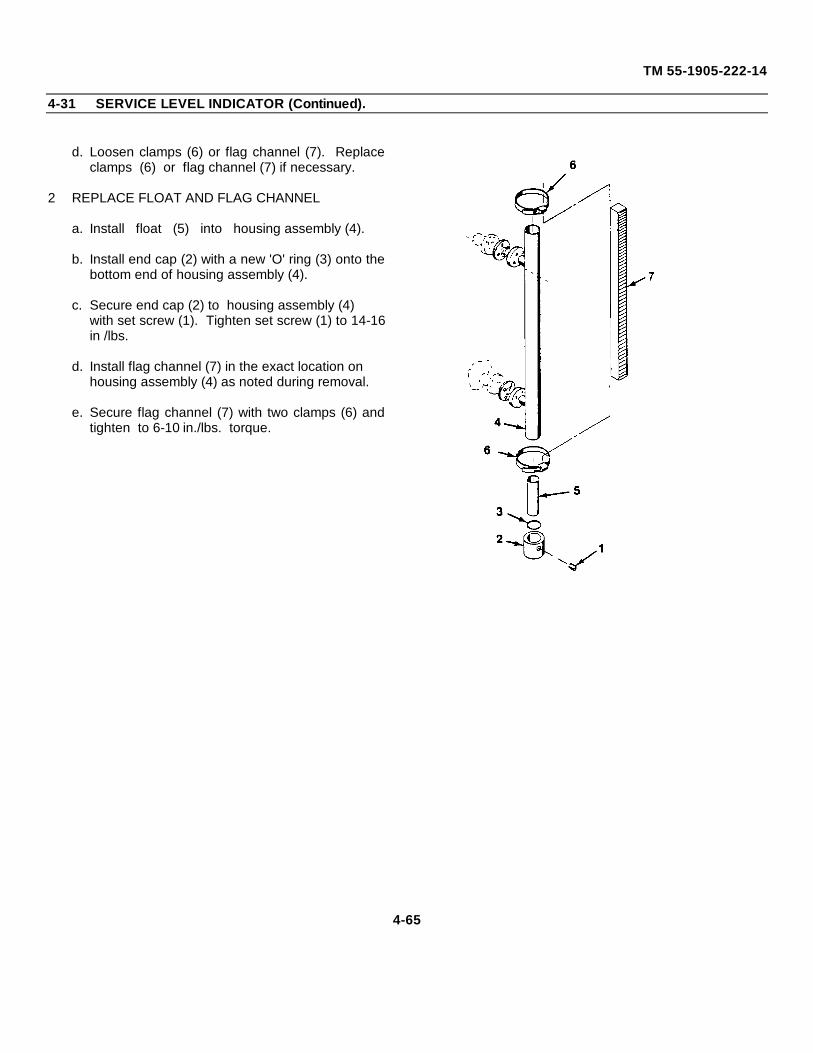
TM 55-1905-222-14
4-31 SERVICE LEVEL INDICATOR (Continued).
d. Loosen clamps (6) or flag channel (7). Replaceclamps (6) or flag channel (7) if necessary.
2 REPLACE FLOAT AND FLAG CHANNEL
a. Install float (5) into housing assembly (4).
b. Install end cap (2) with a new 'O' ring (3) onto thebottom end of housing assembly (4).
c. Secure end cap (2) to housing assembly (4) with set screw (1). Tighten set screw (1) to 14-16in /lbs.
d. Install flag channel (7) in the exact location on housing assembly (4) as noted during removal.
e. Secure flag channel (7) with two clamps (6) andtighten to 6-10 in./lbs. torque.
4-65

TM 55-1905-222-14
MAINTENANCE OF HYDRAULIC STEERING SYSTEM
4-32 ADJUST COUNTERBALANCE VALVE.
The counterbalance valves induce artificial pressure on the low pressure side of the steering cylinders to preventthe rudder from running ahead of the pumps.
INITIAL SETUP
Tools Equipment Conditions
Tool Kit, Mechanic's, Rail Engines running.and Marine5180-00-629-9783
ADJUSTMENT
NOTE
Observe the steering system hydraulic pressure gauge (0-2000 PSI) located on the pilothouseconsole, while adjusting the valves. There are two counterbalance valves, one port and onestarboard. One cannot be adjusted without the other being adjusted.
ADJUST COUNTERBALANCE VALVE
a. Isolate one steering cylinder by closing bothisolation valves (1) on the opposite side.
b. Turn knob (2) to adjust counter- balance valve to bring the hydraulic pressure gauge reading to 1000 psi.
c. Repeat procedure in b and c for second valve.
4-66
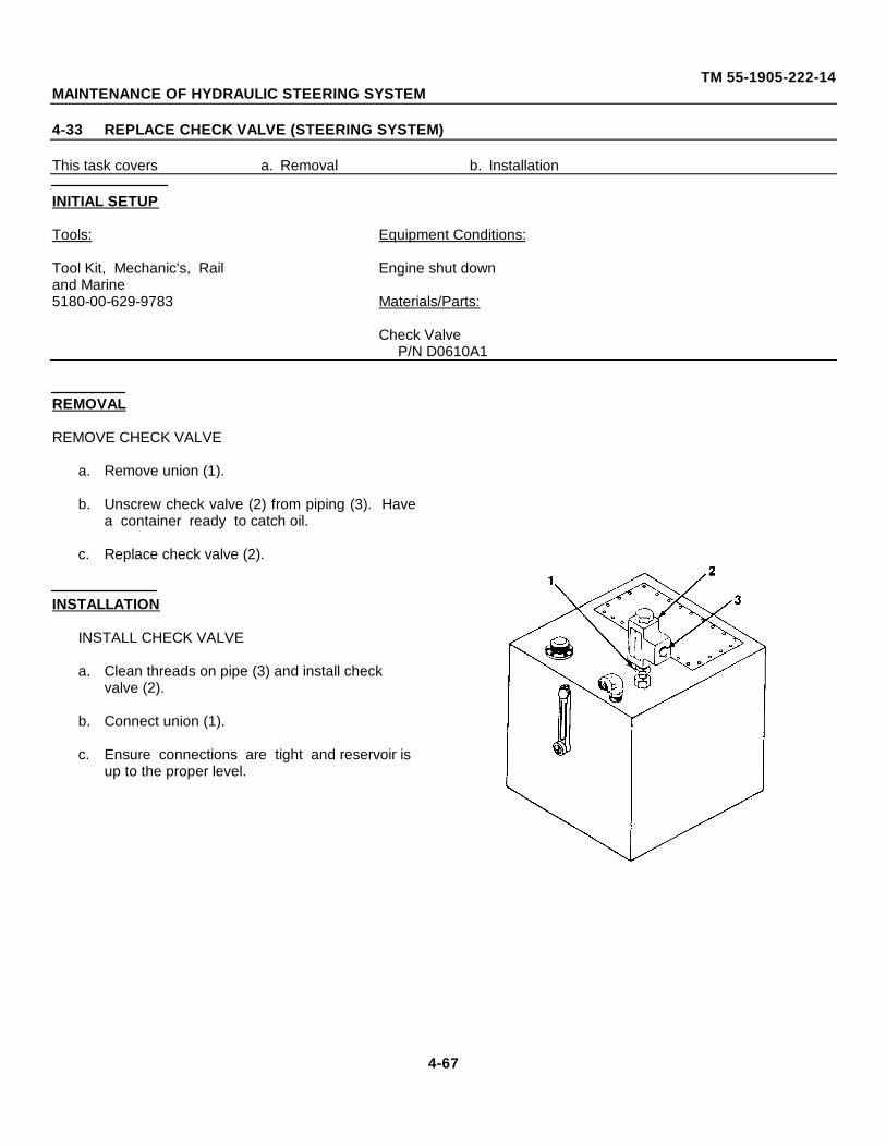
TM 55-1905-222-14MAINTENANCE OF HYDRAULIC STEERING SYSTEM
4-33 REPLACE CHECK VALVE (STEERING SYSTEM)
This task covers a. Removal b. Installation
INITIAL SETUP
Tools: Equipment Conditions:
Tool Kit, Mechanic's, Rail Engine shut downand Marine5180-00-629-9783 Materials/Parts:
Check ValveP/N D0610A1
REMOVAL
REMOVE CHECK VALVE
a. Remove union (1).
b. Unscrew check valve (2) from piping (3). Havea container ready to catch oil.
c. Replace check valve (2).
INSTALLATION
INSTALL CHECK VALVE
a. Clean threads on pipe (3) and install check valve (2).
b. Connect union (1).
c. Ensure connections are tight and reservoir is up to the proper level.
4-67
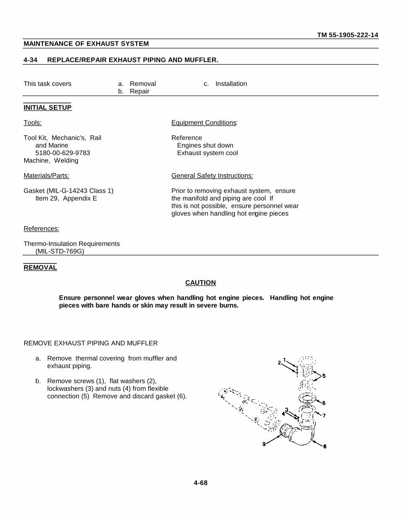
TM 55-1905-222-14MAINTENANCE OF EXHAUST SYSTEM
4-34 REPLACE/REPAIR EXHAUST PIPING AND MUFFLER.
This task covers a. Removal c. Installationb. Repair
INITIAL SETUP
Tools: Equipment Conditions:
Tool Kit, Mechanic's, Rail Referenceand Marine Engines shut down5180-00-629-9783 Exhaust system cool
Machine, Welding
Materials/Parts: General Safety Instructions:
Gasket (MIL-G-14243 Class 1) Prior to removing exhaust system, ensureItem 29, Appendix E the manifold and piping are cool If
this is not possible, ensure personnel weargloves when handling hot engine pieces
References:
Thermo-Insulation Requirements(MIL-STD-769G)
REMOVAL
CAUTION
Ensure personnel wear gloves when handling hot engine pieces. Handling hot enginepieces with bare hands or skin may result in severe burns.
REMOVE EXHAUST PIPING AND MUFFLER
a. Remove thermal covering from muffler and exhaust piping.
b. Remove screws (1), flat washers (2), lockwashers (3) and nuts (4) from flexible connection (5) Remove and discard gasket (6).
4-68
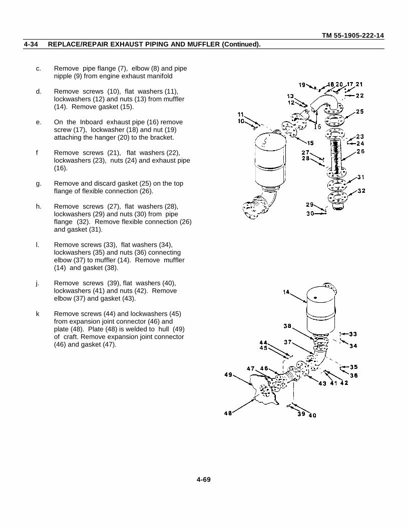
TM 55-1905-222-144-34 REPLACE/REPAIR EXHAUST PIPING AND MUFFLER (Continued).
c. Remove pipe flange (7), elbow (8) and pipe nipple (9) from engine exhaust manifold
d. Remove screws (10), flat washers (11), lockwashers (12) and nuts (13) from muffler (14). Remove gasket (15).
e. On the Inboard exhaust pipe (16) remove screw (17), lockwasher (18) and nut (19) attaching the hanger (20) to the bracket.
f Remove screws (21), flat washers (22), lockwashers (23), nuts (24) and exhaust pipe (16).
g. Remove and discard gasket (25) on the top flange of flexible connection (26).
h. Remove screws (27), flat washers (28), lockwashers (29) and nuts (30) from pipe flange (32). Remove flexible connection (26)and gasket (31).
l. Remove screws (33), flat washers (34), lockwashers (35) and nuts (36) connecting elbow (37) to muffler (14). Remove muffler (14) and gasket (38).
j. Remove screws (39), flat washers (40), lockwashers (41) and nuts (42). Remove elbow (37) and gasket (43).
k Remove screws (44) and lockwashers (45) from expansion joint connector (46) andplate (48). Plate (48) is welded to hull (49) of craft. Remove expansion joint connector (46) and gasket (47).
4-69
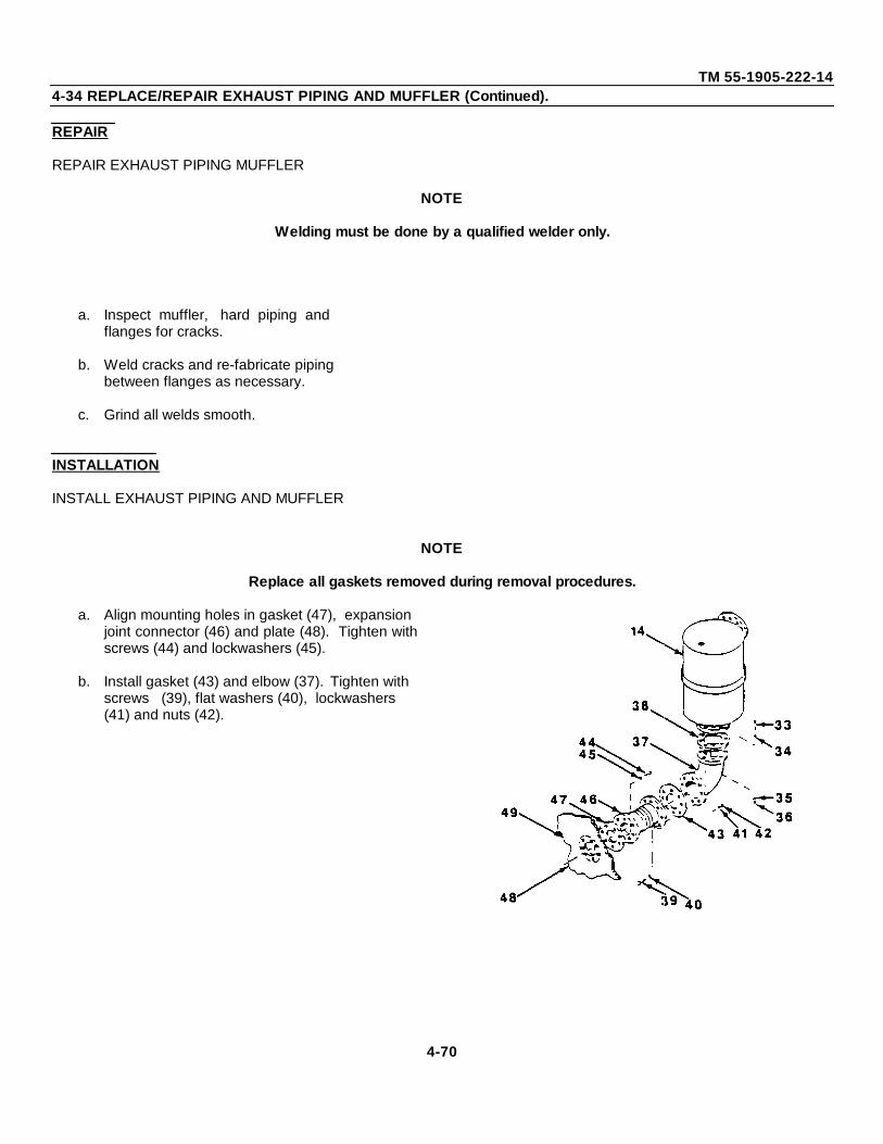
TM 55-1905-222-144-34 REPLACE/REPAIR EXHAUST PIPING AND MUFFLER (Continued).
REPAIR
REPAIR EXHAUST PIPING MUFFLER
NOTE
Welding must be done by a qualified welder only.
a. Inspect muffler, hard piping andflanges for cracks.
b. Weld cracks and re-fabricate pipingbetween flanges as necessary.
c. Grind all welds smooth.
INSTALLATION
INSTALL EXHAUST PIPING AND MUFFLER
NOTE
Replace all gaskets removed during removal procedures.
a. Align mounting holes in gasket (47), expansion joint connector (46) and plate (48). Tighten withscrews (44) and lockwashers (45).
b. Install gasket (43) and elbow (37). Tighten with screws (39), flat washers (40), lockwashers (41) and nuts (42).
4-70
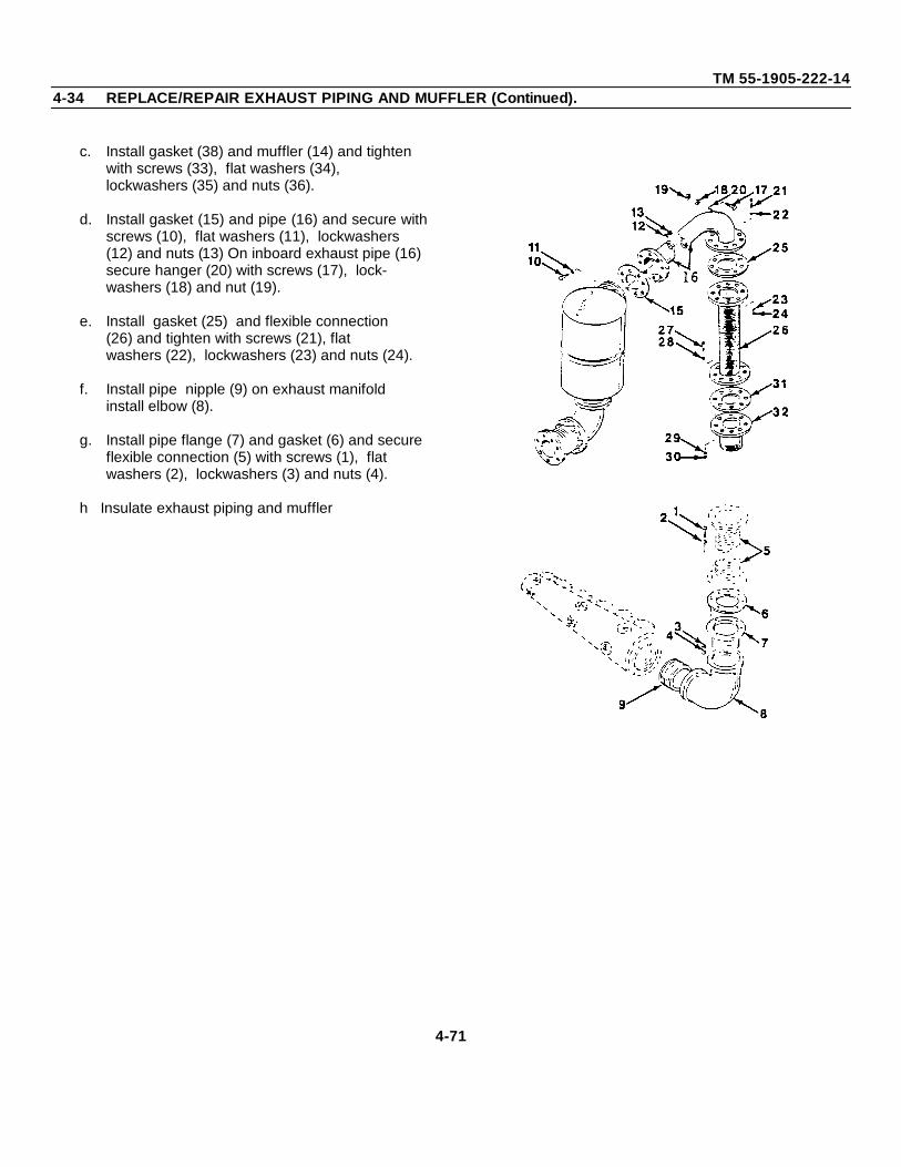
TM 55-1905-222-144-34 REPLACE/REPAIR EXHAUST PIPING AND MUFFLER (Continued).
c. Install gasket (38) and muffler (14) and tighten with screws (33), flat washers (34), lockwashers (35) and nuts (36).
d. Install gasket (15) and pipe (16) and secure withscrews (10), flat washers (11), lockwashers (12) and nuts (13) On inboard exhaust pipe (16) secure hanger (20) with screws (17), lock- washers (18) and nut (19).
e. Install gasket (25) and flexible connection (26) and tighten with screws (21), flat washers (22), lockwashers (23) and nuts (24).
f. Install pipe nipple (9) on exhaust manifold install elbow (8).
g. Install pipe flange (7) and gasket (6) and secure flexible connection (5) with screws (1), flat washers (2), lockwashers (3) and nuts (4).
h Insulate exhaust piping and muffler
4-71
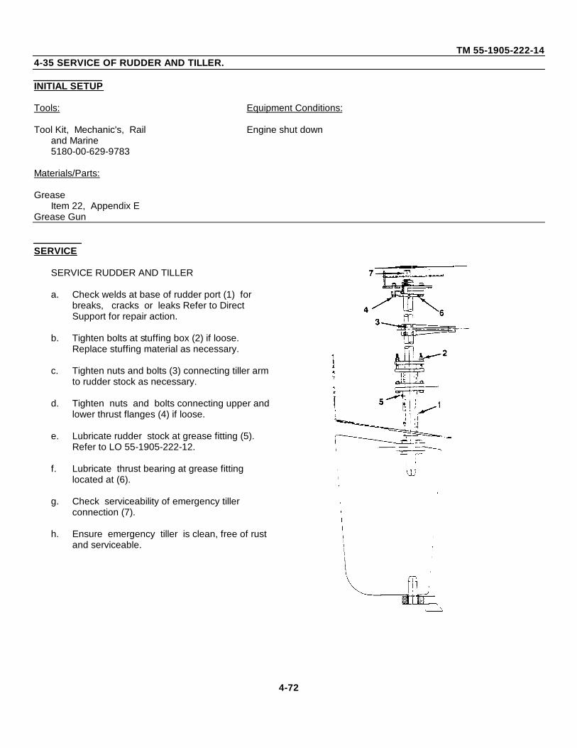
TM 55-1905-222-144-35 SERVICE OF RUDDER AND TILLER.
INITIAL SETUP
Tools: Equipment Conditions:
Tool Kit, Mechanic's, Rail Engine shut downand Marine5180-00-629-9783
Materials/Parts:
GreaseItem 22, Appendix E
Grease Gun
SERVICE
SERVICE RUDDER AND TILLER
a. Check welds at base of rudder port (1) for breaks, cracks or leaks Refer to Direct Support for repair action.
b. Tighten bolts at stuffing box (2) if loose. Replace stuffing material as necessary.
c. Tighten nuts and bolts (3) connecting tiller arm to rudder stock as necessary.
d. Tighten nuts and bolts connecting upper and lower thrust flanges (4) if loose.
e. Lubricate rudder stock at grease fitting (5).Refer to LO 55-1905-222-12.
f. Lubricate thrust bearing at grease fitting located at (6).
g. Check serviceability of emergency tiller connection (7).
h. Ensure emergency tiller is clean, free of rust and serviceable.
4-72

TM 55-1905-222-14
Section V. PREPARATION FOR STORAGE AND SHIPMENT
The procedure for operation for the storage and shipment of the LCM-8 is referred to in Shipment and StorageTechnical Bulletins TB 740-97-2 and TB 730-97-4.
4-73/(4-74 blank)
TM 55-1905-222-14CHAPTER 5
INTERMEDIATE DIRECT SUPPORT MAINTENANCE
Paragraph
Common Tools and Equipment................................ ................................ ................................ ........................5-1
General Maintenance Procedures................................. ................................ ................................ ...................5-5
Repair Alternator................................ ................................ ................................ ................................ ..............5-6
Repair Bilge Pump/Hydraulic Motor Assembly ................................ ................................ ................................ .5-41
Repair Canopy and Mast................................ ................................ ................................ ................................ ..5-7
Repair Check Valve (Steering System) ................................ ................................ ................................ ............5-36
Repair Duplex Strainers (Sea Water System)................................ ................................ ................................ ...5-43
Repair Expansion Tank................................ ................................ ................................ ................................ ....5-51
Repair Parts................................ ................................ ................................ ................................ .....................5-3
Repair Ramp Hoist Hydraulic Check Valve ................................ ................................ ................................ ......5-19
Repair Ramp Winch Hydraulic Motor ................................ ................................ ................................ ...............5-23
Repair Relief Valve . ................................ ................................ ................................ ............5-33
Repair Rudder................................ ................................ ................................ ................................ ..................5-38
Repair Voids and Compartments ................................. ................................ ................................ ....................5-15
Replace Accumulator . ................................ ................................ ................................ ................................ .....5-45
Replace Bilge Pump/Hydraulic Motor Assembly................................ ................................ ...............................5-40
Replace Clutch Linkage ................................ ................................ ................................ ................................ ...5-9
Replace Control Valve (Starting System) ................................ ................................ ................................ .........5-47
Replace Counterbalance Valve................................ ................................ ................................ ........................5-35
Replace Duplex Strainer (Sea Water System)................................ ................................ ................................ ..5-42
Replace Engine/Transmission Instruments................................ ................................ ................................ .......5-10
Replace Expansion Tank................................ ................................ ................................ ................................ ..5-50
Replace Filters (Starting System)................................ ................................ ................................ .....................5-46
Replace Flow Divider ................................ ................................ ................................ ................................ .......5-34
5-1
TM 55-1905-222-14
CHAPTER 5
INTERMEDIATE DIRECT SUPPORT MAINTENANCE - Continued
Paragraph
Replace Hand Pump (Starting System)................................ ................................ ................................ ............5-49
Replace/Repair Hatches and Void Covers................................ ................................ ................................ ........5-13
Replace Helm Unit ................................ ................................ ................................ ................................ ...........5-31
Replace/Repair Hull, Bitts, Chocks and Tiedowns................................ ................................ ..........................5-12
Replace Hydraulic Gauges, Rudder Angle Indicator and Ammeter................................ ................................ ..5-11
Replace Latch Mechanism................................ ................................ ................................ ...............................5-26
Replace Ramp Cables, Sheaves and Chains................................ ................................ ................................ ..5-27
Replace Ramp and Hinge Pins................................ ................................ ................................ .........................5-25
Replace Ramp Hoist Control Valve ................................ ................................ ................................ ..................5-17
Replace Ramp Hoist Hand Pump................................ ................................ ................................ .....................5-20
Replace Ramp Hoist Hydraulic Check Valve................................ ................................ ................................ ....5-18
Replace Ramp Hoist Hydraulic Pump................................ ................................ ................................ ...............5-16
Replace Ramp Locking Hydraulic Cylinders................................ ................................ ................................ .....5-21
Replace Ramp Seal ................................ ................................ ................................ ................................ .........5-28
Replace Ramp Winch ................................ ................................ ................................ ................................ ......5-24
Replace Ramp Winch Hydraulic Motor................................ ................................ ................................ .............5-22
Replace Recharging Pump................................. ................................ ................................ ..............................5-44
Replace Relief Valve (Steering System)................................ ................................ ................................ ...........5-32
Replace Rudder................................ ................................ ................................ ................................ ...............5-37
Replace Rudder Angle Transmitter................................ ................................ ................................ ...................5-39
Replace/Repair Stanchions and Lifelines................................ ................................ ................................ .........5-14
Replace Starting Motor................................ ................................ ................................ ................................ .....5-48
Replace Steering Cylinders................................ ................................ ................................ ..............................5-30
Replace Steering Pump ................................ ................................ ................................ ................................ ...5-29
Replace Throttle Linkage ................................ ................................ ................................ ................................ .5-8
5-2

TM 55-1905-222-14
CHAPTER 5
INTERMEDIATE DIRECT SUPPORT MAINTENANCE - Continued
Paragraph
Special Tools, TMDE and Support Equipment................................ ................................ ................................ .5-2
Troubleshooting Procedures................................ ................................ ................................ .............................5-4
5-3
TM 55-1905-222-14
Section I. REPAIR PARTS; SPECIAL TOOLS; TEST, MEASUREMENT, AND DIAGNOSTIC EQUIPMENT (TMDE); AND SUPPORT EQUIPMENT.
5-1 COMMON TOOLS AND EQUIPMENT.
For authorized common tools and equipment, refer to the Modified Table of Organizational Equipment(MTOE) applicable to your unit.
5-2 SPECIAL TOOLS, TMDE, AND SUPPORT EQUIPMENT.
Any special tools or equipment required by direct support maintenance personnel to perform maintenance on thelanding craft is listed In Appendix B of this manual.
5-3 REPAIR PARTS.
Repair parts are listed and illustrated in the repair parts and special tools list (TM 55-1905-222-24P) covering directsupport maintenance of this equipment.
Section II. TROUBLESHOOTING
5-4 TROUBLESHOOTING PROCEDURES.
This paragraph provides information useful in diagnosing and correcting unsatisfactory operation or failure of LCM-8 systems and equipment. Troubleshooting procedures in this manual are limited to the basic craft. Refer to TM5-2815-231-14 for engine and transmission troubleshooting procedures. Before using the troubleshooting procedures,ensure that all applicable operating procedures have been performed.
NOTE
The table lists the malfunctions which may occur during the service life of the equipment.Replace all defective parts when repairing an equipment unless machining or other repairprocess can return the part to reusable condition.
TM 55-1905-222-14
Troubleshooting
MALFUNCTION
TEST OR INSPECTION
CORRECTIVE ACTION
1. ALTERNATOR FAILS TO CHARGE.
Step 1. Check for excessively worn, sticky or intermittent brushes.
Replace brushes (para 5-6).
Step 2. Test for defective rectifier diodes.
Disassemble alternator and replace diodes (para 6-5).
Step 3. Test for open rotor winding.
Disassemble alternator and verify rotor winding continuity.
Replace rotor If open (para. 6-5).
2. LOW OR UNSTEADY CHARGING RATE
Step 1. Check for open, grounded or shorted turns In stator coils.
Disassemble alternator and replace stator (para 6-5).
Step 2. Check for grounded or shorted turns In rotor winding.
Disassemble alternator and replace rotor (para 6-5).
Step 3. Check for open or shorted rectifier diodes.
Disassemble alternator and replace diodes (para 6-5).
3. NOISY ALTERNATOR
Check to see if alternator bearings are worn.
Disassemble alternator and replace worn or defective bearings (para 6-5).
5-5
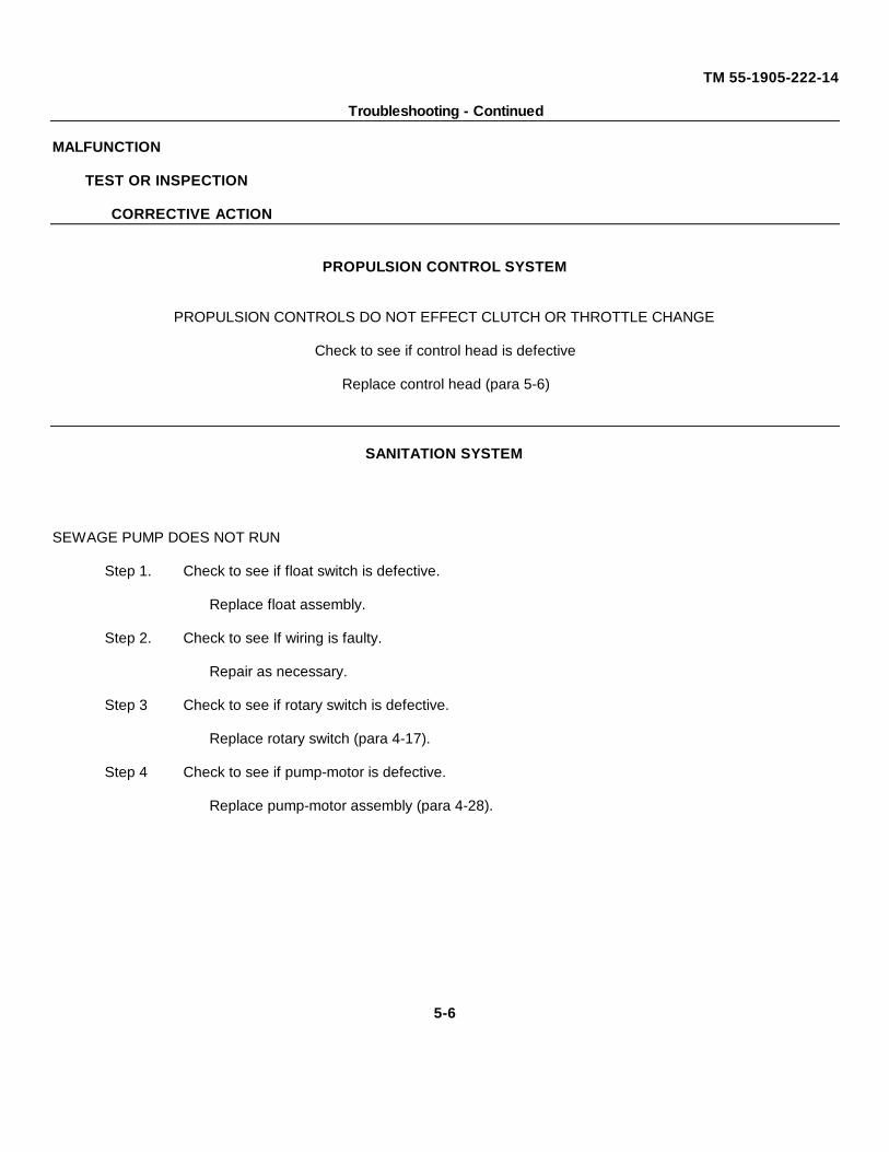
TM 55-1905-222-14
Troubleshooting - Continued
MALFUNCTION
TEST OR INSPECTION
CORRECTIVE ACTION
PROPULSION CONTROL SYSTEM
PROPULSION CONTROLS DO NOT EFFECT CLUTCH OR THROTTLE CHANGE
Check to see if control head is defective
Replace control head (para 5-6)
SANITATION SYSTEM
SEWAGE PUMP DOES NOT RUN
Step 1. Check to see if float switch is defective.
Replace float assembly.
Step 2. Check to see If wiring is faulty.
Repair as necessary.
Step 3 Check to see if rotary switch is defective.
Replace rotary switch (para 4-17).
Step 4 Check to see if pump-motor is defective.
Replace pump-motor assembly (para 4-28).
5-6
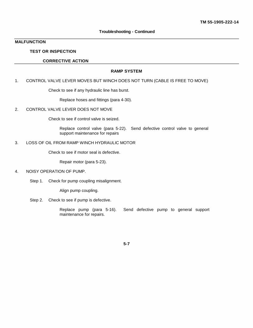
TM 55-1905-222-14
Troubleshooting - Continued
MALFUNCTION
TEST OR INSPECTION
CORRECTIVE ACTION
RAMP SYSTEM
1. CONTROL VALVE LEVER MOVES BUT WINCH DOES NOT TURN (CABLE IS FREE TO MOVE)
Check to see if any hydraulic line has burst.
Replace hoses and fittings (para 4-30).
2. CONTROL VALVE LEVER DOES NOT MOVE
Check to see if control valve is seized.
Replace control valve (para 5-22). Send defective control valve to generalsupport maintenance for repairs
3. LOSS OF OIL FROM RAMP WINCH HYDRAULIC MOTOR
Check to see if motor seal is defective.
Repair motor (para 5-23).
4. NOISY OPERATION OF PUMP.
Step 1. Check for pump coupling misalignment.
Align pump coupling.
Step 2. Check to see if pump is defective.
Replace pump (para 5-16). Send defective pump to general supportmaintenance for repairs.
5-7
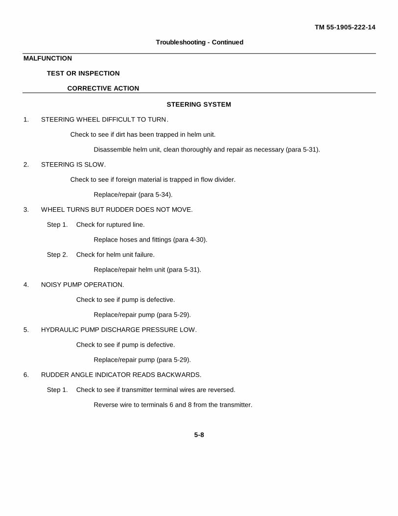
TM 55-1905-222-14
Troubleshooting - Continued
MALFUNCTION
TEST OR INSPECTION
CORRECTIVE ACTION
STEERING SYSTEM
1. STEERING WHEEL DIFFICULT TO TURN.
Check to see if dirt has been trapped in helm unit.
Disassemble helm unit, clean thoroughly and repair as necessary (para 5-31).
2. STEERING IS SLOW.
Check to see if foreign material is trapped in flow divider.
Replace/repair (para 5-34).
3. WHEEL TURNS BUT RUDDER DOES NOT MOVE.
Step 1. Check for ruptured line.
Replace hoses and fittings (para 4-30).
Step 2. Check for helm unit failure.
Replace/repair helm unit (para 5-31).
4. NOISY PUMP OPERATION.
Check to see if pump is defective.
Replace/repair pump (para 5-29).
5. HYDRAULIC PUMP DISCHARGE PRESSURE LOW.
Check to see if pump is defective.
Replace/repair pump (para 5-29).
6. RUDDER ANGLE INDICATOR READS BACKWARDS.
Step 1. Check to see if transmitter terminal wires are reversed.
Reverse wire to terminals 6 and 8 from the transmitter.
5-8
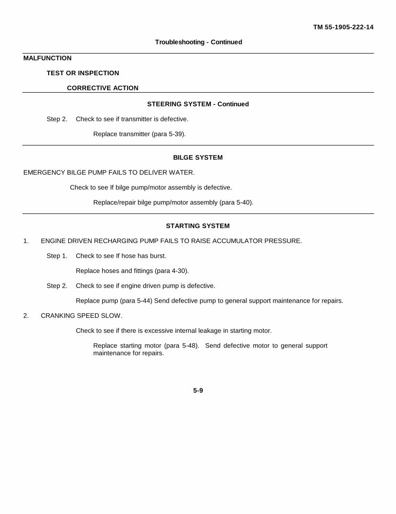
TM 55-1905-222-14
Troubleshooting - Continued
MALFUNCTION
TEST OR INSPECTION
CORRECTIVE ACTION
STEERING SYSTEM - Continued
Step 2. Check to see if transmitter is defective.
Replace transmitter (para 5-39).
BILGE SYSTEM
EMERGENCY BILGE PUMP FAILS TO DELIVER WATER.
Check to see If bilge pump/motor assembly is defective.
Replace/repair bilge pump/motor assembly (para 5-40).
STARTING SYSTEM
1. ENGINE DRIVEN RECHARGING PUMP FAILS TO RAISE ACCUMULATOR PRESSURE.
Step 1. Check to see If hose has burst.
Replace hoses and fittings (para 4-30).
Step 2. Check to see if engine driven pump is defective.
Replace pump (para 5-44) Send defective pump to general support maintenance for repairs.
2. CRANKING SPEED SLOW.
Check to see if there is excessive internal leakage in starting motor.
Replace starting motor (para 5-48). Send defective motor to general supportmaintenance for repairs.
5-9
TM 55-1905-222-14
Troubleshooting - Continued
MALFUNCTION
TEST OR INSPECTION
CORRECTIVE ACTION
STARTING SYSTEM - Continued
3. HAND PUMP FAILS TO CHARGE SYSTEM.
Step 1. Check to see if hose has burst.
Replace hoses and fittings (para 4-30).
Step 2. Check to see if piston seal rings are damaged.
Replace hand pump (para. 5-49). Send defective hand pump to general supportmaintenance for repairs.
4. LOW/LOSS OF ACCUMULATOR PRECHARGE..
Check for damaged seal ring.
Replace accumulator (para 5-45). Send defective accumulator to general supportmaintenance for repairs.
5. HIGH PRESSURE IN SYSTEM (ABOVE 3500 PSI).
Step 1. Check to see If relief valve is defective.
Replace and adjust relief valve.
Step 2. Check to see if unloading valve In recharging pump is operating improperly.
Replace pump (para 5-44). Send defective pump to general supportmaintenance for repairs.
6. ENGINE FAILS TO START IN ALL STARTING MODES.
Step 1. Check to see if control valve is defective.
Replace control valve (para. 5-47).
Step 2. Check to see if starting motor is defective.
Replace starting motor (para 5-48). Send starting motor to general supportmaintenance for repairs
5-10
TM 55-1905-222-14
Troubleshooting - Continued
MALFUNCTION
TEST OR INSPECTION
CORRECTIVE ACTION
FUEL SYSTEM
SUFFICIENT FUEL NOT AVAILABLE TO ENGINES
Check to see if there is a break in the fuel hose.
Replace hoses and fittings (para 4-30).
5-11

TM 55-1905-222-14
SECTION III. MAINTENANCE PROCEDURES
5-5 GENERAL MAINTENANCE PROCEDURES.
This chapter contains maintenance procedures that are the responsibility of direct support maintenance, asauthorized by the Maintenance Allocation Chart (MAC).
5-12
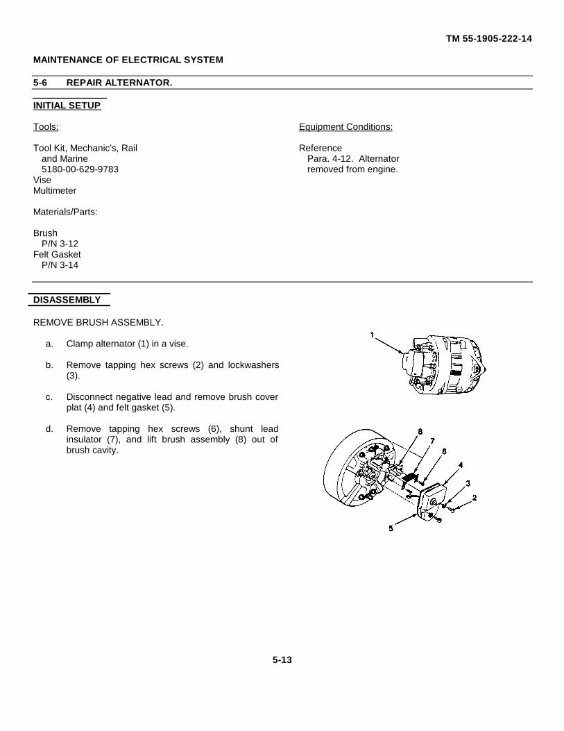
TM 55-1905-222-14
MAINTENANCE OF ELECTRICAL SYSTEM
5-6 REPAIR ALTERNATOR.
INITIAL SETUP
Tools: Equipment Conditions:
Tool Kit, Mechanic’s, Rail Referenceand Marine Para. 4-12. Alternator5180-00-629-9783 removed from engine.
ViseMultimeter
Materials/Parts:
BrushP/N 3-12
Felt GasketP/N 3-14
DISASSEMBLY
REMOVE BRUSH ASSEMBLY.
a. Clamp alternator (1) in a vise.
b. Remove tapping hex screws (2) and lockwashers(3).
c. Disconnect negative lead and remove brush coverplat (4) and felt gasket (5).
d. Remove tapping hex screws (6), shunt leadinsulator (7), and lift brush assembly (8) out ofbrush cavity.
5-13
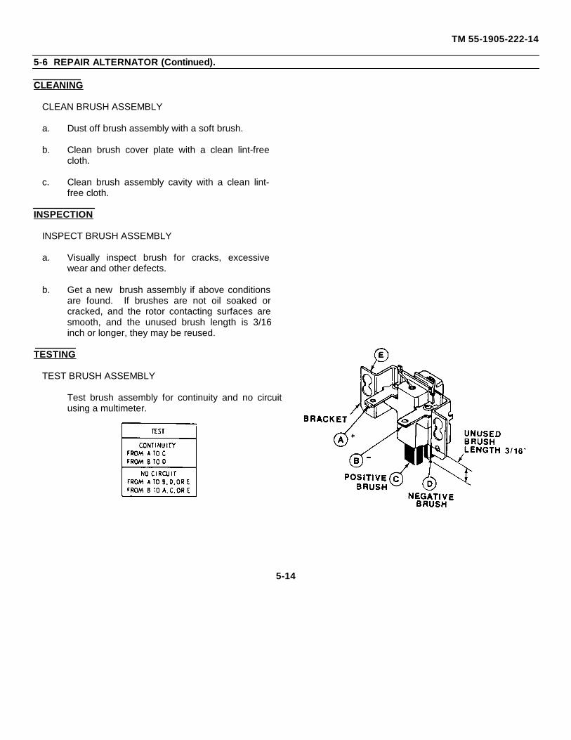
TM 55-1905-222-14
5-6 REPAIR ALTERNATOR (Continued).
CLEANING
CLEAN BRUSH ASSEMBLY
a. Dust off brush assembly with a soft brush.
b. Clean brush cover plate with a clean lint-freecloth.
c. Clean brush assembly cavity with a clean lint-free cloth.
INSPECTION
INSPECT BRUSH ASSEMBLY
a. Visually inspect brush for cracks, excessivewear and other defects.
b. Get a new brush assembly if above conditionsare found. If brushes are not oil soaked orcracked, and the rotor contacting surfaces aresmooth, and the unused brush length is 3/16inch or longer, they may be reused.
TESTING
TEST BRUSH ASSEMBLY
Test brush assembly for continuity and no circuitusing a multimeter.
5-14
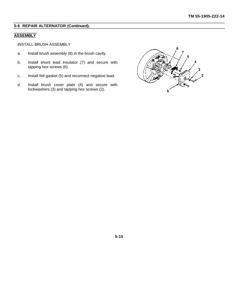
TM 55-1905-222-14
5-6 REPAIR ALTERNATOR (Continued).
ASSEMBLY
INSTALL BRUSH ASSEMBLY
a. Install brush assembly (8) in the brush cavity.
b. Install shunt lead Insulator (7) and secure withtapping hex screws (6).
c. Install felt gasket (5) and reconnect negative lead.
d. Install brush cover plate (4) and secure withlockwashers (3) and tapping hex screws (2).
5-15
TM 55-1905-222-14
MAINTENANCE OF CANOPY, MAST, WINDOWS AND WIPERS
5-7 REPAIR CANOPY AND MAST.
INITIAL SETUP
Tools: Equipment Conditions:
Tool Kit, Mechanic's, Rail All power off. All accessories con-and Marine nected to canopy are disconnected5180-00-629-9783 (ladder, searchlight, wipers assembly).
Machine, Welding Mast to be lowered to its lowestconfiguration
Personnel required: General Safety Instructions:
(1) Certified welder. Ensure area is safe for "HOTWORK." Post fire watch asnecessary.
REPAIR
REPAIR CANOPY.
a. Strip paint from canopy around area to berepaired. Ensure area is down to bare metaland free of rust.
b. Weld damaged area so as to make itwatertight and retain its original strength.
c. Prime and paint area so it is restored to itsoriginal condition.
d. Reinstall accessories.
5-16
TM 55-1905-222-14
5-7 REPAIR CANOPY AND MAST (Continued).
REPAIR MAST.
a. Lower mast to the deck as per para 4-20.
b. Strip paint from mast around area to berepaired. Ensure are is down to bare metal andfree of rust.
c. Weld damaged area so as to make it watertightand retain its original strength.
d. Prime and paint area so it is restored to itsoriginal condition. Refer to TB 43-0114.
e. Raise mast to its upright and locked position asper para 4-20.
5-17
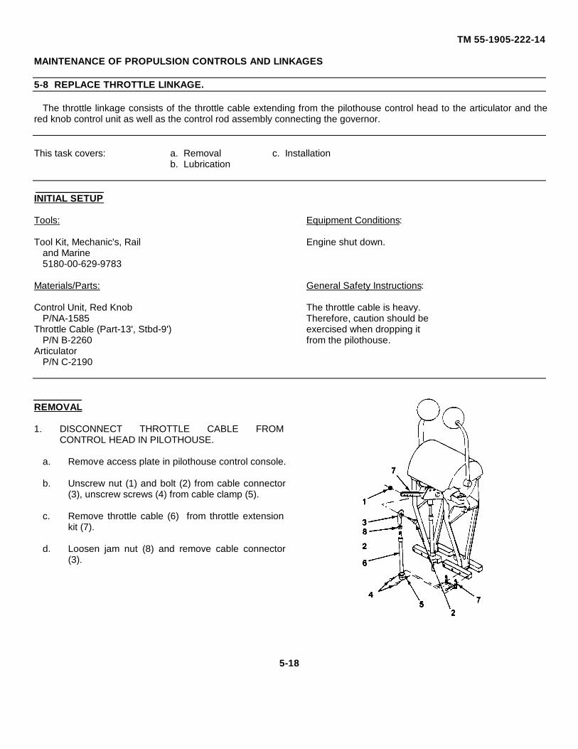
TM 55-1905-222-14
MAINTENANCE OF PROPULSION CONTROLS AND LINKAGES
5-8 REPLACE THROTTLE LINKAGE.
The throttle linkage consists of the throttle cable extending from the pilothouse control head to the articulator and thered knob control unit as well as the control rod assembly connecting the governor.
This task covers: a. Removal c. Installationb. Lubrication
INITIAL SETUP
Tools: Equipment Conditions:
Tool Kit, Mechanic's, Rail Engine shut down.and Marine5180-00-629-9783
Materials/Parts: General Safety Instructions:
Control Unit, Red Knob The throttle cable is heavy.P/NA-1585 Therefore, caution should be
Throttle Cable (Part-13', Stbd-9') exercised when dropping itP/N B-2260 from the pilothouse.
ArticulatorP/N C-2190
REMOVAL
1. DISCONNECT THROTTLE CABLE FROMCONTROL HEAD IN PILOTHOUSE.
a. Remove access plate in pilothouse control console.
b. Unscrew nut (1) and bolt (2) from cable connector(3), unscrew screws (4) from cable clamp (5).
c. Remove throttle cable (6) from throttle extensionkit (7).
d. Loosen jam nut (8) and remove cable connector(3).
5-18
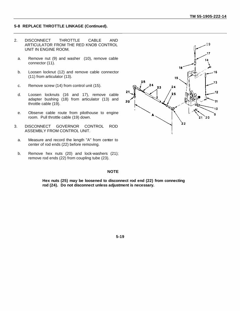
TM 55-1905-222-14
5-8 REPLACE THROTTLE LINKAGE (Continued).
2. DISCONNECT THROTTLE CABLE ANDARTICULATOR FROM THE RED KNOB CONTROLUNIT IN ENGINE ROOM.
a. Remove nut (9) and washer (10), remove cableconnector (11).
b. Loosen locknut (12) and remove cable connector(11) from articulator (13).
c. Remove screw (14) from control unit (15).
d. Loosen locknuts (16 and 17), remove cableadapter bushing (18) from articulator (13) andthrottle cable (19).
e. Observe cable route from pilothouse to engineroom. Pull throttle cable (19) down.
3. DISCONNECT GOVERNOR CONTROL RODASSEMBLY FROM CONTROL UNIT.
a. Measure and record the length "A" from center tocenter of rod ends (22) before removing.
b. Remove hex nuts (20) and lock-washers (21);remove rod ends (22) from coupling tube (23).
NOTE
Hex nuts (25) may be loosened to disconnect rod end (22) from connectingrod (24). Do not disconnect unless adjustment is necessary.
5-19
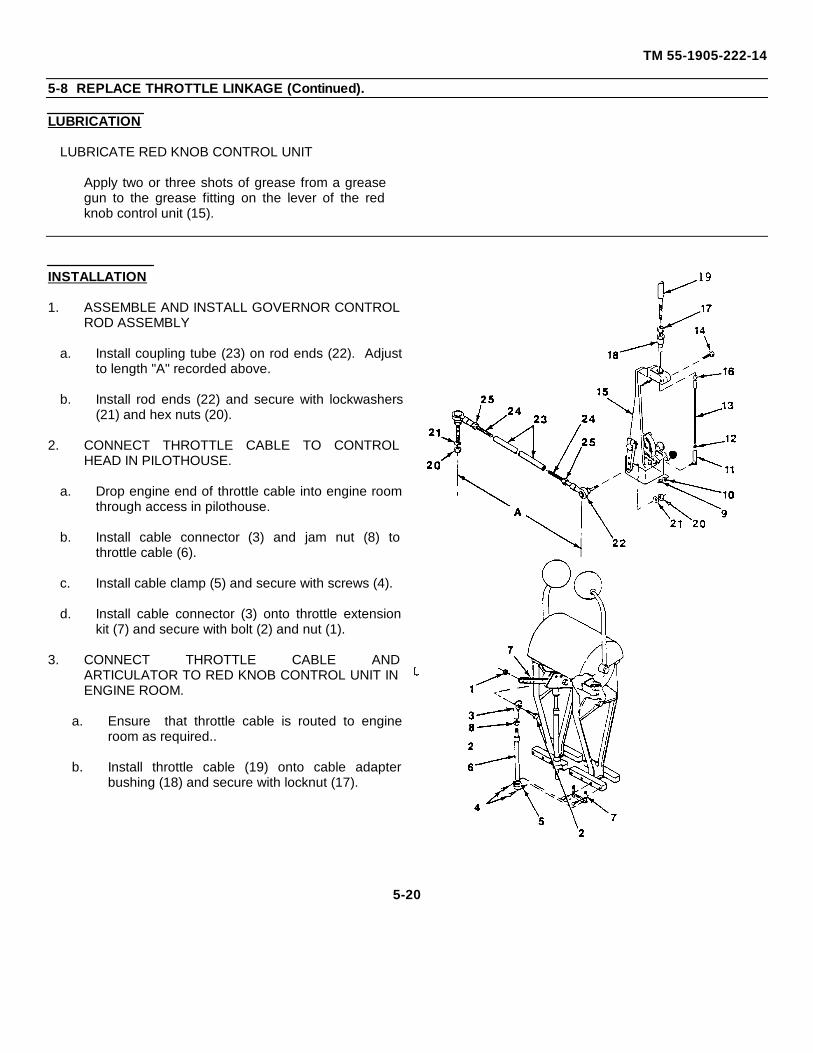
TM 55-1905-222-14
5-8 REPLACE THROTTLE LINKAGE (Continued).
LUBRICATION
LUBRICATE RED KNOB CONTROL UNIT
Apply two or three shots of grease from a greasegun to the grease fitting on the lever of the redknob control unit (15).
INSTALLATION
1. ASSEMBLE AND INSTALL GOVERNOR CONTROLROD ASSEMBLY
a. Install coupling tube (23) on rod ends (22). Adjustto length "A" recorded above.
b. Install rod ends (22) and secure with lockwashers(21) and hex nuts (20).
2. CONNECT THROTTLE CABLE TO CONTROLHEAD IN PILOTHOUSE.
a. Drop engine end of throttle cable into engine roomthrough access in pilothouse.
b. Install cable connector (3) and jam nut (8) tothrottle cable (6).
c. Install cable clamp (5) and secure with screws (4).
d. Install cable connector (3) onto throttle extensionkit (7) and secure with bolt (2) and nut (1).
3. CONNECT THROTTLE CABLE ANDARTICULATOR TO RED KNOB CONTROL UNIT INENGINE ROOM.
a. Ensure that throttle cable is routed to engineroom as required..
b. Install throttle cable (19) onto cable adapterbushing (18) and secure with locknut (17).
5-20
TM 55-1905-222-14
5-8 REPLACE THROTTLE LINKAGE (Continued).
c. Pass cable adapter bushing (18) through hole incontrol unit (15). Hand tighten screw (14).(Make sure only the bottom end of the bushingis clamped in control unit.)
d. Install locknut (16) and articulator (13) ontothreaded rod end of cable adapter bushing (18).
e. Install locknut (12) and cable connector (11) onarticulator (13).
f. Install cable connector (11) and secure withwasher (10) and nut (9).
g. Adjust throttle linkage as necessary.
5-21
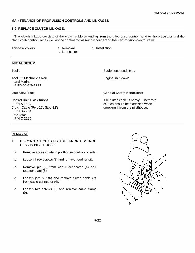
TM 55-1905-222-14
MAINTENANCE OF PROPULSION CONTROLS AND LINKAGES
5-9 REPLACE CLUTCH LINKAGE.
The clutch linkage consists of the clutch cable extending from the pilothouse control head to the articulator and theblack knob control unit as well as the control rod assembly connecting the transmission control valve.
This task covers: a. Removal c. Installationb. Lubrication
INITIAL SETUP
Tools: Equipment conditions:
Tool Kit, Mechanic's Rail Engine shut down.and Marine5180-00-629-9783
Materials/Parts: General Safety Instructions:
Control Unit, Black Knobs The clutch cable is heavy. Therefore,P/N A-1585 caution should be exercised when
Clutch Cable (Port-15', Stbd-12') dropping it from the pilothouse.P/N B-2260
ArticulatorP/N C-2190
REMOVAL
1. DISCONNECT CLUTCH CABLE FROM CONTROLHEAD IN PILOTHOUSE.
a. Remove access plate in pilothouse control console.
b. Loosen three screws (1) and remove retainer (2).
c. Remove pin (3) from cable connector (4) andretainer plate (5).
d. Loosen jam nut (6) and remove clutch cable (7)from cable connector (4).
e. Loosen two screws (8) and remove cable clamp(9).
5-22
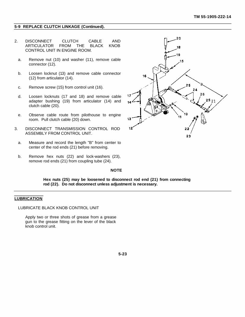
TM 55-1905-222-14
5-9 REPLACE CLUTCH LINKAGE (Continued).
2. DISCONNECT CLUTCH CABLE ANDARTICULATOR FROM THE BLACK KNOBCONTROL UNIT IN ENGINE ROOM.
a. Remove nut (10) and washer (11), remove cableconnector (12).
b. Loosen locknut (13) and remove cable connector(12) from articulator (14).
c. Remove screw (15) from control unit (16).
d. Loosen locknuts (17 and 18) and remove cableadapter bushing (19) from articulator (14) andclutch cable (20).
e. Observe cable route from pilothouse to engineroom. Pull clutch cable (20) down.
3. DISCONNECT TRANSMISSION CONTROL RODASSEMBLY FROM CONTROL UNIT.
a. Measure and record the length "B" from center tocenter of the rod ends (21) before removing.
b. Remove hex nuts (22) and lock-washers (23),remove rod ends (21) from coupling tube (24).
NOTE
Hex nuts (25) may be loosened to disconnect rod end (21) from connectingrod (22). Do not disconnect unless adjustment is necessary.
LUBRICATION
LUBRICATE BLACK KNOB CONTROL UNIT
Apply two or three shots of grease from a greasegun to the grease fitting on the lever of the blackknob control unit.
5-23
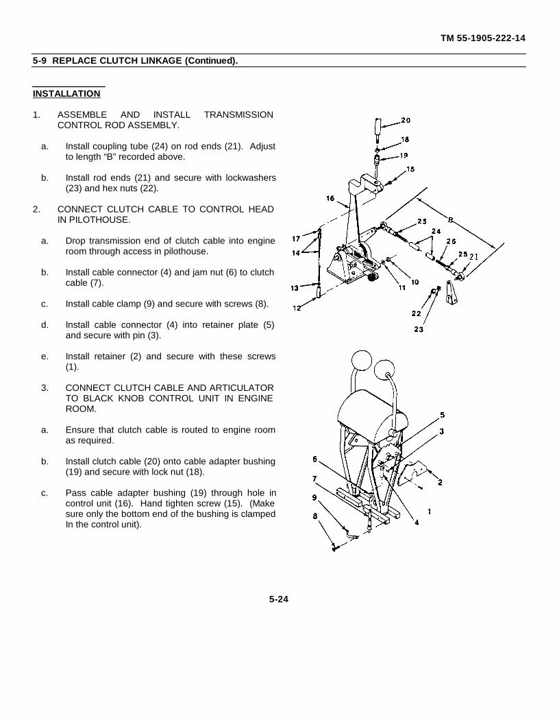
TM 55-1905-222-14
5-9 REPLACE CLUTCH LINKAGE (Continued).
INSTALLATION
1. ASSEMBLE AND INSTALL TRANSMISSIONCONTROL ROD ASSEMBLY.
a. Install coupling tube (24) on rod ends (21). Adjustto length “B" recorded above.
b. Install rod ends (21) and secure with lockwashers(23) and hex nuts (22).
2. CONNECT CLUTCH CABLE TO CONTROL HEADIN PILOTHOUSE.
a. Drop transmission end of clutch cable into engineroom through access in pilothouse.
b. Install cable connector (4) and jam nut (6) to clutchcable (7).
c. Install cable clamp (9) and secure with screws (8).
d. Install cable connector (4) into retainer plate (5)and secure with pin (3).
e. Install retainer (2) and secure with these screws(1).
3. CONNECT CLUTCH CABLE AND ARTICULATORTO BLACK KNOB CONTROL UNIT IN ENGINEROOM.
a. Ensure that clutch cable is routed to engine roomas required.
b. Install clutch cable (20) onto cable adapter bushing(19) and secure with lock nut (18).
c. Pass cable adapter bushing (19) through hole incontrol unit (16). Hand tighten screw (15). (Makesure only the bottom end of the bushing is clampedIn the control unit).
5-24
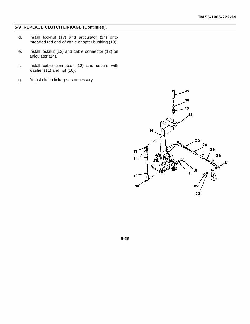
TM 55-1905-222-14
5-9 REPLACE CLUTCH LINKAGE (Continued).
d. Install locknut (17) and articulator (14) ontothreaded rod end of cable adapter bushing (19).
e. Install locknut (13) and cable connector (12) onarticulator (14).
f. Install cable connector (12) and secure withwasher (11) and nut (10).
g. Adjust clutch linkage as necessary.
5-25
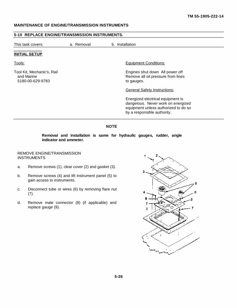
TM 55-1905-222-14
MAINTENANCE OF ENGINE/TRANSMISSION INSTRUMENTS
5-10 REPLACE ENGINE/TRANSMISSION INSTRUMENTS.
This task covers: a. Removal b. Installation
INITIAL SETUP
Tools: Equipment Conditions:
Tool Kit, Mechanic's, Rail Engines shut down All power offand Marine Remove all oil pressure from lines5180-00-629-9783 to gauges.
General Safety Instructions:
Energized electrical equipment isdangerous. Never work on energizedequipment unless authorized to do soby a responsible authority.
NOTE
Removal and installation is same for hydraulic gauges, rudder, angleindicator and ammeter.
REMOVE ENGINE/TRANSMISSIONINSTRUMENTS
a. Remove screws (1), clear cover (2) and gasket (3).
b. Remove screws (4) and lift instrument panel (5) togain access to instruments.
c. Disconnect tube or wires (6) by removing flare nut(7).
d. Remove male connector (8) (if applicable) andreplace gauge (9).
5-26
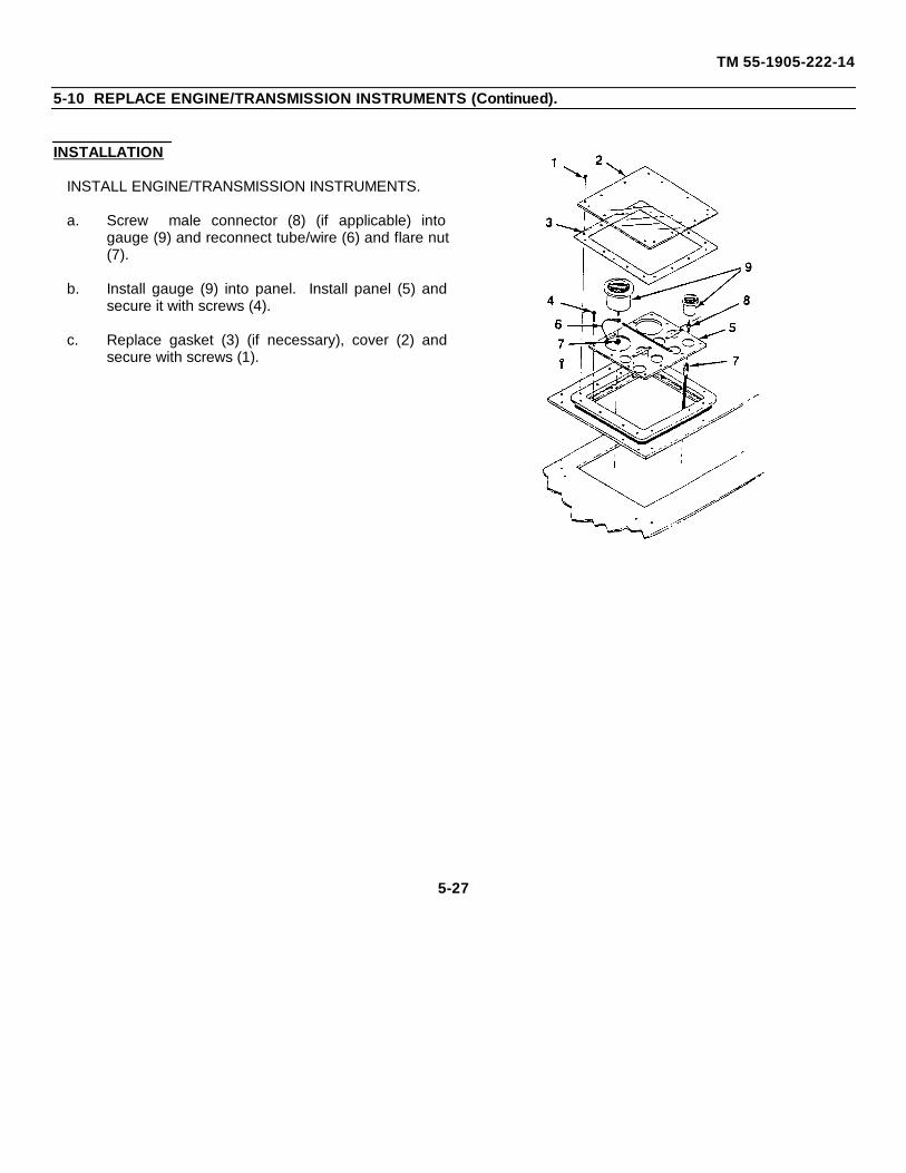
TM 55-1905-222-14
5-10 REPLACE ENGINE/TRANSMISSION INSTRUMENTS (Continued).
INSTALLATION
INSTALL ENGINE/TRANSMISSION INSTRUMENTS.
a. Screw male connector (8) (if applicable) intogauge (9) and reconnect tube/wire (6) and flare nut(7).
b. Install gauge (9) into panel. Install panel (5) andsecure it with screws (4).
c. Replace gasket (3) (if necessary), cover (2) andsecure with screws (1).
5-27
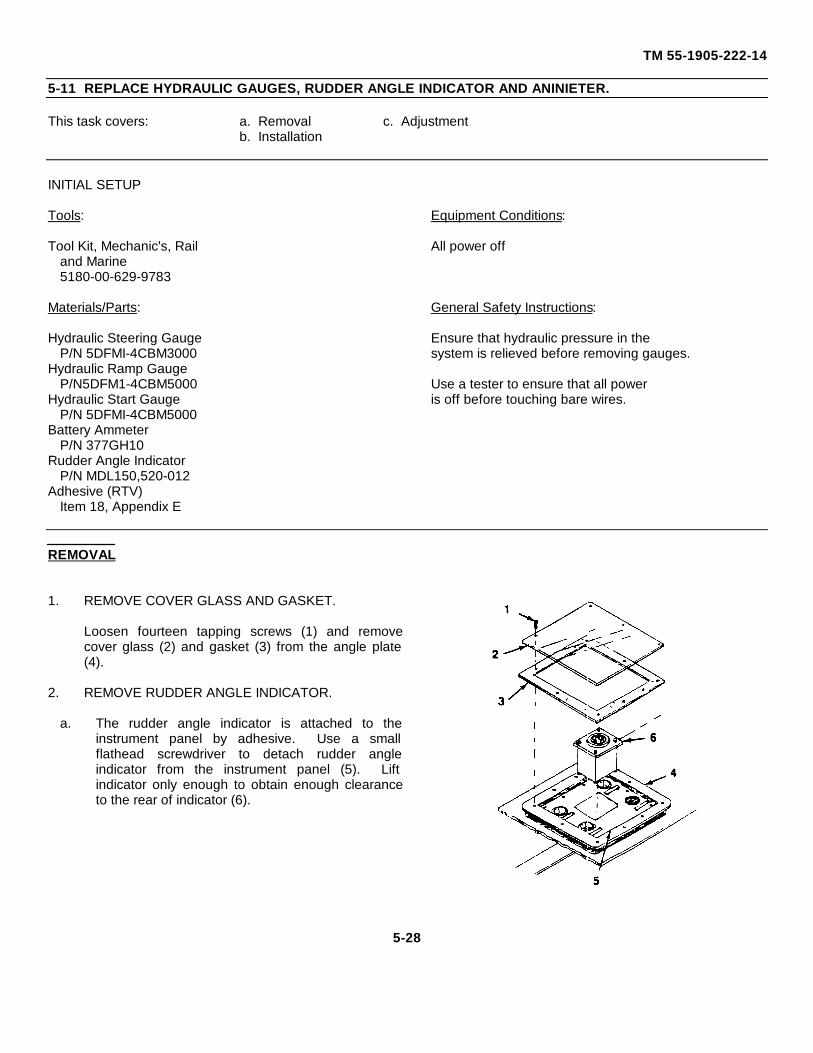
TM 55-1905-222-14
5-11 REPLACE HYDRAULIC GAUGES, RUDDER ANGLE INDICATOR AND ANINIETER.
This task covers: a. Removal c. Adjustmentb. Installation
INITIAL SETUP
Tools: Equipment Conditions:
Tool Kit, Mechanic's, Rail All power offand Marine5180-00-629-9783
Materials/Parts: General Safety Instructions:
Hydraulic Steering Gauge Ensure that hydraulic pressure in theP/N 5DFMI-4CBM3000 system is relieved before removing gauges.
Hydraulic Ramp GaugeP/N5DFM1-4CBM5000 Use a tester to ensure that all power
Hydraulic Start Gauge is off before touching bare wires.P/N 5DFMI-4CBM5000
Battery AmmeterP/N 377GH10
Rudder Angle IndicatorP/N MDL150,520-012
Adhesive (RTV)Item 18, Appendix E
REMOVAL
1. REMOVE COVER GLASS AND GASKET.
Loosen fourteen tapping screws (1) and removecover glass (2) and gasket (3) from the angle plate(4).
2. REMOVE RUDDER ANGLE INDICATOR.
a. The rudder angle indicator is attached to theinstrument panel by adhesive. Use a smallflathead screwdriver to detach rudder angleindicator from the instrument panel (5). Liftindicator only enough to obtain enough clearanceto the rear of indicator (6).
5-28
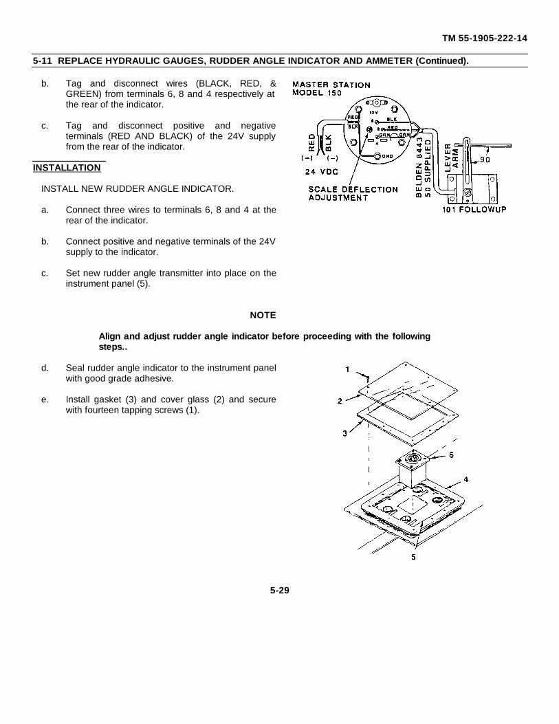
TM 55-1905-222-14
5-11 REPLACE HYDRAULIC GAUGES, RUDDER ANGLE INDICATOR AND AMMETER (Continued).
b. Tag and disconnect wires (BLACK, RED, &GREEN) from terminals 6, 8 and 4 respectively atthe rear of the indicator.
c. Tag and disconnect positive and negativeterminals (RED AND BLACK) of the 24V supplyfrom the rear of the indicator.
INSTALLATION
INSTALL NEW RUDDER ANGLE INDICATOR.
a. Connect three wires to terminals 6, 8 and 4 at therear of the indicator.
b. Connect positive and negative terminals of the 24Vsupply to the indicator.
c. Set new rudder angle transmitter into place on theinstrument panel (5).
NOTE
Align and adjust rudder angle indicator before proceeding with the followingsteps..
d. Seal rudder angle indicator to the instrument panelwith good grade adhesive.
e. Install gasket (3) and cover glass (2) and securewith fourteen tapping screws (1).
5-29
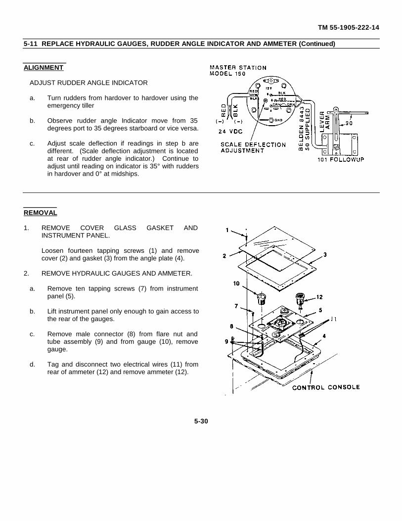
TM 55-1905-222-14
5-11 REPLACE HYDRAULIC GAUGES, RUDDER ANGLE INDICATOR AND AMMETER (Continued)
ALIGNMENT
ADJUST RUDDER ANGLE INDICATOR
a. Turn rudders from hardover to hardover using theemergency tiller
b. Observe rudder angle Indicator move from 35degrees port to 35 degrees starboard or vice versa.
c. Adjust scale deflection if readings in step b aredifferent. (Scale deflection adjustment is locatedat rear of rudder angle indicator.) Continue toadjust until reading on indicator is 35° with ruddersin hardover and 0° at midships.
REMOVAL
1. REMOVE COVER GLASS GASKET ANDINSTRUMENT PANEL.
Loosen fourteen tapping screws (1) and removecover (2) and gasket (3) from the angle plate (4).
2. REMOVE HYDRAULIC GAUGES AND AMMETER.
a. Remove ten tapping screws (7) from instrumentpanel (5).
b. Lift instrument panel only enough to gain access tothe rear of the gauges.
c. Remove male connector (8) from flare nut andtube assembly (9) and from gauge (10), removegauge.
d. Tag and disconnect two electrical wires (11) fromrear of ammeter (12) and remove ammeter (12).
5-30
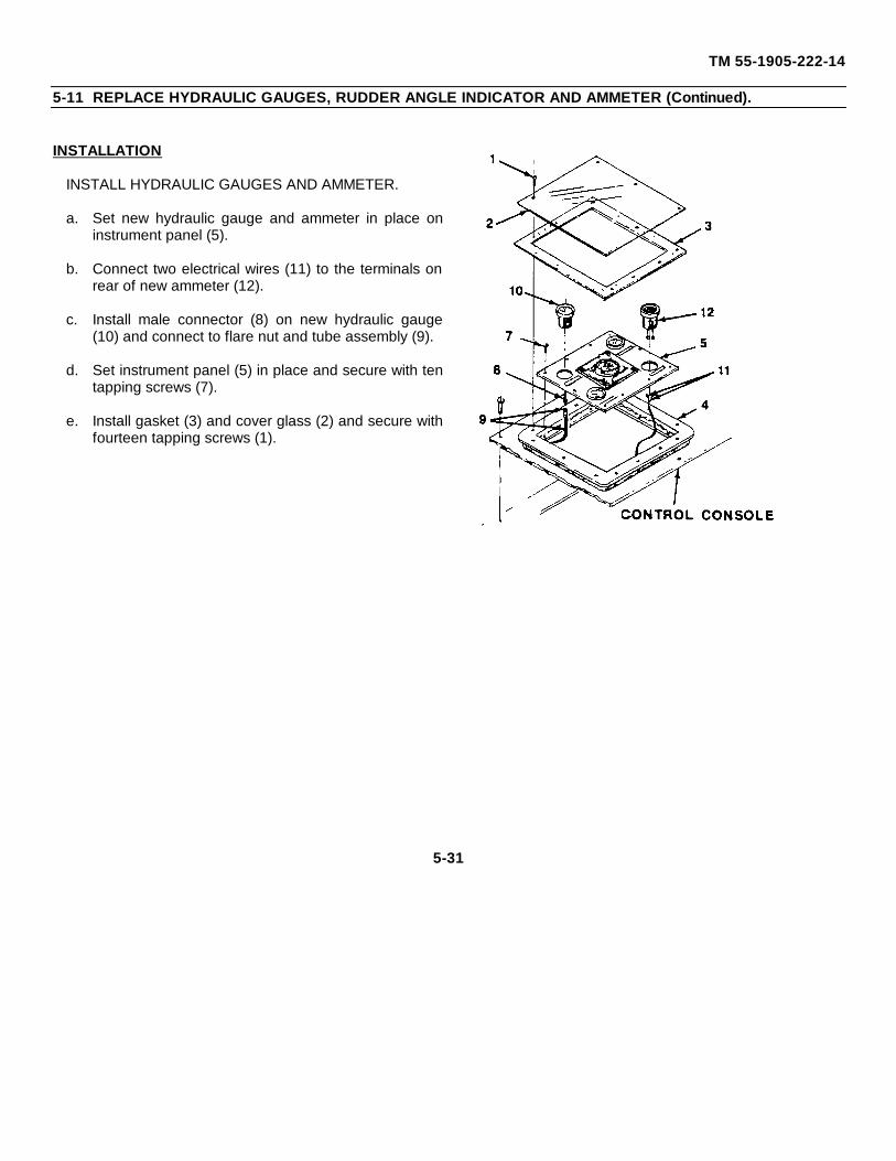
TM 55-1905-222-14
5-11 REPLACE HYDRAULIC GAUGES, RUDDER ANGLE INDICATOR AND AMMETER (Continued).
INSTALLATION
INSTALL HYDRAULIC GAUGES AND AMMETER.
a. Set new hydraulic gauge and ammeter in place oninstrument panel (5).
b. Connect two electrical wires (11) to the terminals onrear of new ammeter (12).
c. Install male connector (8) on new hydraulic gauge(10) and connect to flare nut and tube assembly (9).
d. Set instrument panel (5) in place and secure with tentapping screws (7).
e. Install gasket (3) and cover glass (2) and secure withfourteen tapping screws (1).
5-31
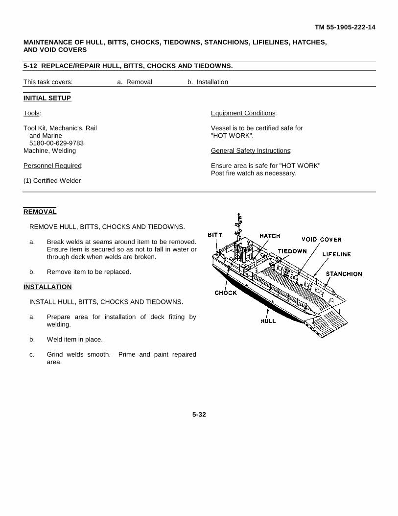
TM 55-1905-222-14
MAINTENANCE OF HULL, BITTS, CHOCKS, TIEDOWNS, STANCHIONS, LIFIELINES, HATCHES,AND VOID COVERS
5-12 REPLACE/REPAIR HULL, BITTS, CHOCKS AND TIEDOWNS.
This task covers: a. Removal b. Installation
INITIAL SETUP
Tools: Equipment Conditions:
Tool Kit, Mechanic's, Rail Vessel is to be certified safe forand Marine "HOT WORK".5180-00-629-9783
Machine, Welding General Safety Instructions:
Personnel Required: Ensure area is safe for "HOT WORK"Post fire watch as necessary.
(1) Certified Welder
REMOVAL
REMOVE HULL, BITTS, CHOCKS AND TIEDOWNS.
a. Break welds at seams around item to be removed.Ensure item is secured so as not to fall in water orthrough deck when welds are broken.
b. Remove item to be replaced.
INSTALLATION
INSTALL HULL, BITTS, CHOCKS AND TIEDOWNS.
a. Prepare area for installation of deck fitting bywelding.
b. Weld item in place.
c. Grind welds smooth. Prime and paint repairedarea.
5-32
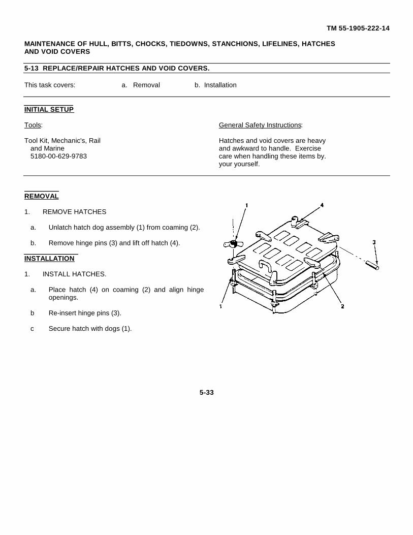
TM 55-1905-222-14
MAINTENANCE OF HULL, BITTS, CHOCKS, TIEDOWNS, STANCHIONS, LIFELINES, HATCHESAND VOID COVERS
5-13 REPLACE/REPAIR HATCHES AND VOID COVERS.
This task covers: a. Removal b. Installation
INITIAL SETUP
Tools: General Safety Instructions:
Tool Kit, Mechanic's, Rail Hatches and void covers are heavyand Marine and awkward to handle. Exercise5180-00-629-9783 care when handling these items by.
your yourself.
REMOVAL
1. REMOVE HATCHES
a. Unlatch hatch dog assembly (1) from coaming (2).
b. Remove hinge pins (3) and lift off hatch (4).
INSTALLATION
1. INSTALL HATCHES.
a. Place hatch (4) on coaming (2) and align hingeopenings.
b Re-insert hinge pins (3).
c Secure hatch with dogs (1).
5-33
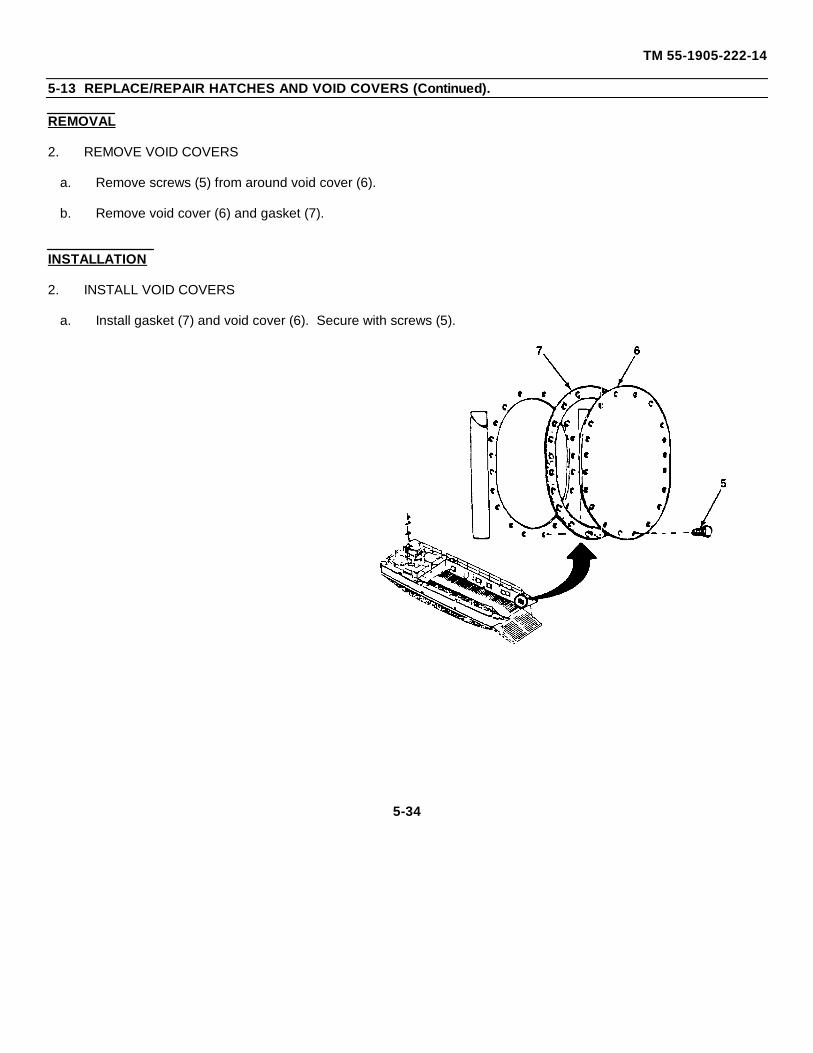
TM 55-1905-222-14
5-13 REPLACE/REPAIR HATCHES AND VOID COVERS (Continued).
REMOVAL
2. REMOVE VOID COVERS
a. Remove screws (5) from around void cover (6).
b. Remove void cover (6) and gasket (7).
INSTALLATION
2. INSTALL VOID COVERS
a. Install gasket (7) and void cover (6). Secure with screws (5).
5-34
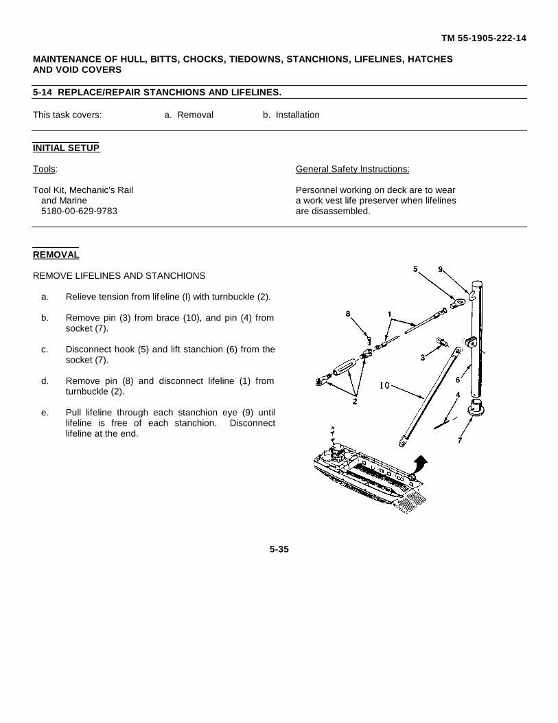
TM 55-1905-222-14
MAINTENANCE OF HULL, BITTS, CHOCKS, TIEDOWNS, STANCHIONS, LIFELINES, HATCHESAND VOID COVERS
5-14 REPLACE/REPAIR STANCHIONS AND LIFELINES.
This task covers: a. Removal b. Installation
INITIAL SETUP
Tools: General Safety Instructions:
Tool Kit, Mechanic's Rail Personnel working on deck are to wearand Marine a work vest life preserver when lifelines5180-00-629-9783 are disassembled.
REMOVAL
REMOVE LIFELINES AND STANCHIONS
a. Relieve tension from lifeline (I) with turnbuckle (2).
b. Remove pin (3) from brace (10), and pin (4) fromsocket (7).
c. Disconnect hook (5) and lift stanchion (6) from thesocket (7).
d. Remove pin (8) and disconnect lifeline (1) fromturnbuckle (2).
e. Pull lifeline through each stanchion eye (9) untillifeline is free of each stanchion. Disconnectlifeline at the end.
5-35
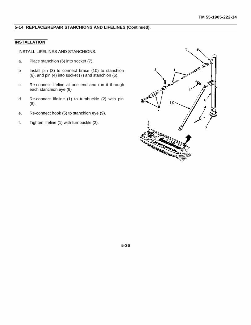
TM 55-1905-222-14
5-14 REPLACE/REPAIR STANCHIONS AND LIFELINES (Continued).
INSTALLATION
INSTALL LIFELINES AND STANCHIONS.
a. Place stanchion (6) into socket (7).
b Install pin (3) to connect brace (10) to stanchion(6), and pin (4) into socket (7) and stanchion (6).
c. Re-connect lifeline at one end and run it througheach stanchion eye (9)
d. Re-connect lifeline (1) to turnbuckle (2) with pin(8).
e. Re-connect hook (5) to stanchion eye (9).
f. Tighten lifeline (1) with turnbuckle (2).
5-36
TM 55-1905-222-14
MAINTENANCE OF VOIDS AND COMPARTMENTS
5-15 REPAIR VOIDS AND COMPARTMENTS.
INITIAL SETUP
Tools: Equipment Conditions: Tool Kit, Mechanic's Rail Vessel and compartment
and Marine certified safe for "HOT WORK".5180-00-629-9783 In certain instances vessel
Machine, Welding should be drydocked when damageis below waterline.
Personnel Required:General Safety Instructions:
(1) Certified WelderEnsure void or compartment is gas freefrom explosive vapors and is safe forentry. Post a fire watch during "HOTWORK".
REPAIR
REPAIR VOIDS AND COMPARTMENTS.
a. Remove all water and contamination from voidsto ascertain where the damage is.
b. Prepare area for repair by removing paint andrust.
c. Repair damage by welding and/or patchingarea. Replace damaged areas as necessary.
d. Grind welds smooth. Prime and paint areaupon completion of repairs.
e. If voids are damaged due to heavy rust, theentire void should be sandblasted to baremetal, primed and painted
5-37
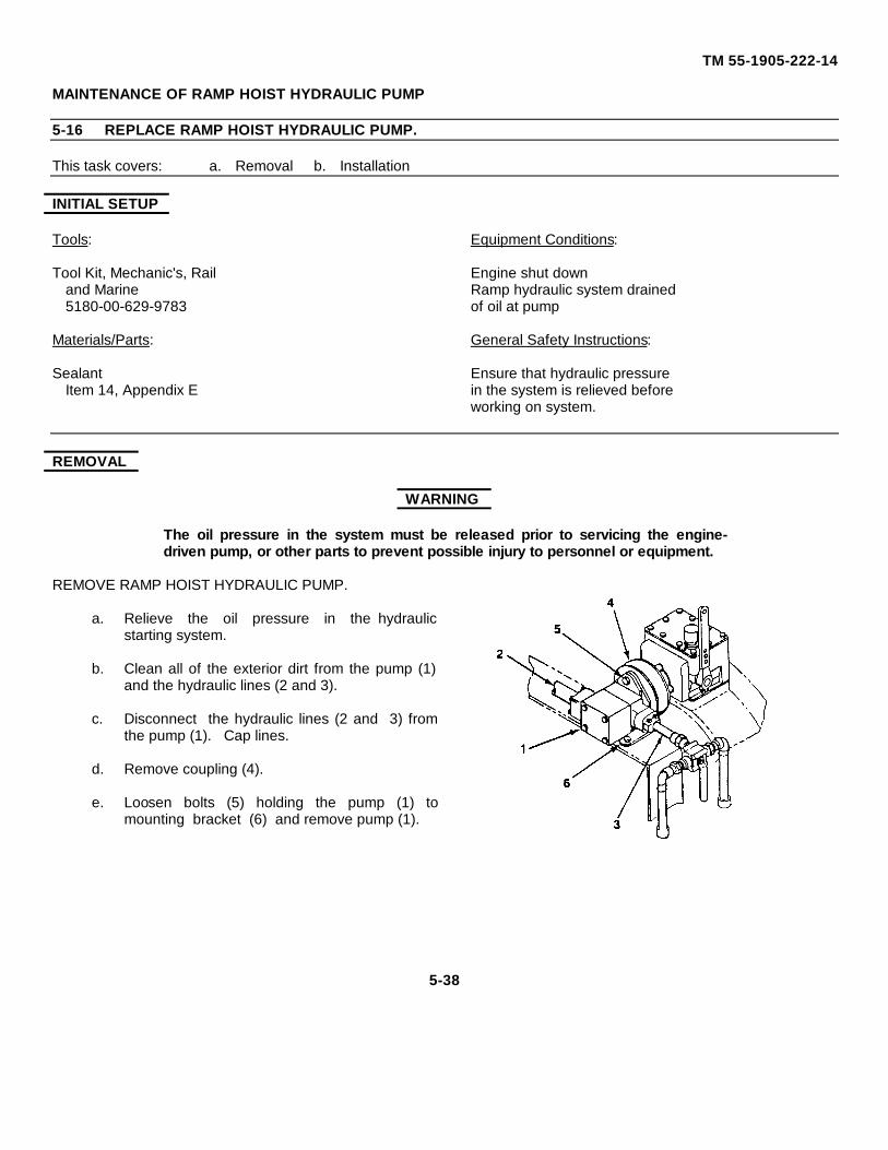
TM 55-1905-222-14
MAINTENANCE OF RAMP HOIST HYDRAULIC PUMP
5-16 REPLACE RAMP HOIST HYDRAULIC PUMP.
This task covers: a. Removal b. Installation
INITIAL SETUP
Tools: Equipment Conditions:
Tool Kit, Mechanic's, Rail Engine shut downand Marine Ramp hydraulic system drained5180-00-629-9783 of oil at pump
Materials/Parts: General Safety Instructions:
Sealant Ensure that hydraulic pressureItem 14, Appendix E in the system is relieved before
working on system.
REMOVAL
WARNING
The oil pressure in the system must be released prior to servicing the engine-driven pump, or other parts to prevent possible injury to personnel or equipment.
REMOVE RAMP HOIST HYDRAULIC PUMP.
a. Relieve the oil pressure in the hydraulicstarting system.
b. Clean all of the exterior dirt from the pump (1)and the hydraulic lines (2 and 3).
c. Disconnect the hydraulic lines (2 and 3) fromthe pump (1). Cap lines.
d. Remove coupling (4).
e. Loosen bolts (5) holding the pump (1) tomounting bracket (6) and remove pump (1).
5-38
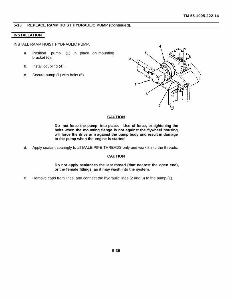
TM 55-1905-222-14
5-16 REPLACE RAMP HOIST HYDRAULIC PUMP (Continued).
INSTALLATION
INSTALL RAMP HOIST HYDRAULIC PUMP.
a. Position pump (1) in place on mountingbracket (6).
b. Install coupling (4).
c. Secure pump (1) with bolts (5).
CAUTION
Do not force the pump into place. Use of force, or tightening thebolts when the mounting flange is not against the flywheel housing,will force the drive arm against the pump body and result in damageto the pump when the engine is started.
d. Apply sealant sparingly to all MALE PIPE THREADS only and work it into the threads.
CAUTION
Do not apply sealant to the last thread (that nearest the open end),or the female fittings, as it may wash into the system.
e. Remove caps from lines, and connect the hydraulic lines (2 and 3) to the pump (1).
5-39
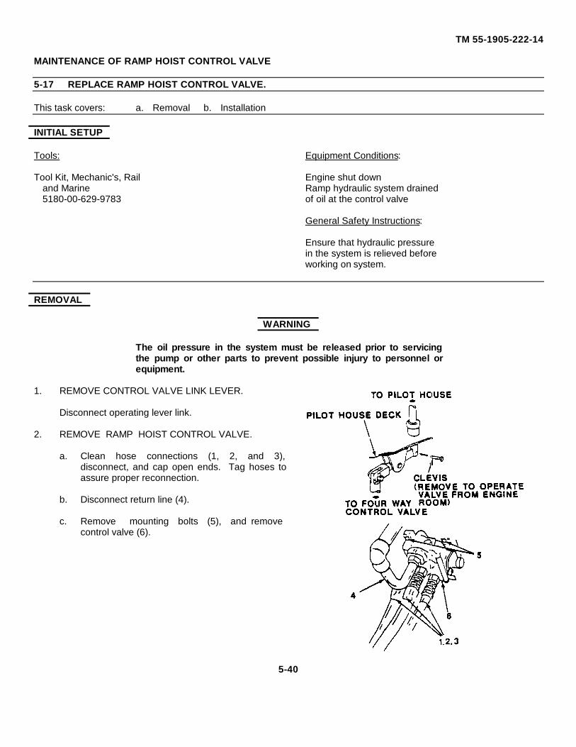
TM 55-1905-222-14
MAINTENANCE OF RAMP HOIST CONTROL VALVE
5-17 REPLACE RAMP HOIST CONTROL VALVE.
This task covers: a. Removal b. Installation
INITIAL SETUP
Tools: Equipment Conditions:
Tool Kit, Mechanic's, Rail Engine shut downand Marine Ramp hydraulic system drained5180-00-629-9783 of oil at the control valve
General Safety Instructions:
Ensure that hydraulic pressurein the system is relieved beforeworking on system.
REMOVAL
WARNING
The oil pressure in the system must be released prior to servicingthe pump or other parts to prevent possible injury to personnel orequipment.
1. REMOVE CONTROL VALVE LINK LEVER.
Disconnect operating lever link.
2. REMOVE RAMP HOIST CONTROL VALVE.
a. Clean hose connections (1, 2, and 3),disconnect, and cap open ends. Tag hoses toassure proper reconnection.
b. Disconnect return line (4).
c. Remove mounting bolts (5), and removecontrol valve (6).
5-40
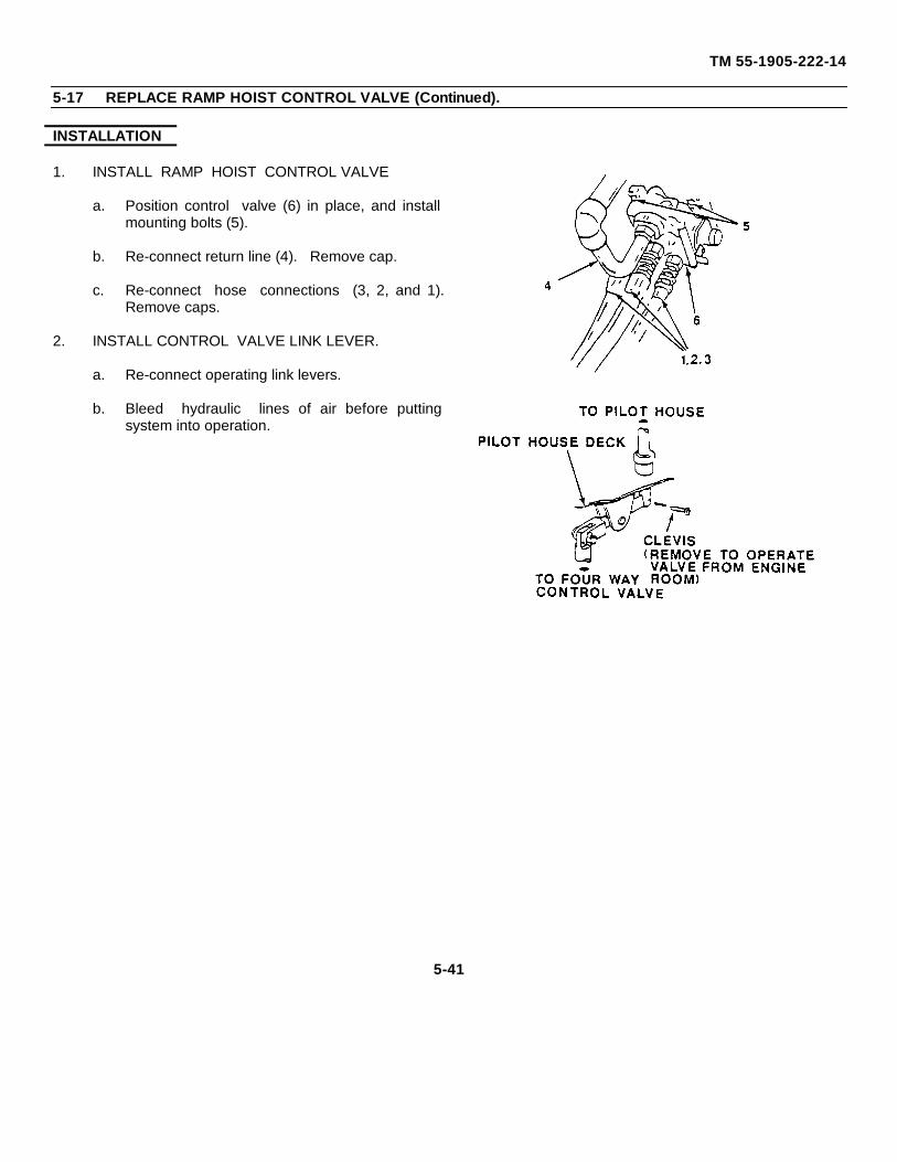
TM 55-1905-222-14
5-17 REPLACE RAMP HOIST CONTROL VALVE (Continued).
INSTALLATION
1. INSTALL RAMP HOIST CONTROL VALVE
a. Position control valve (6) in place, and installmounting bolts (5).
b. Re-connect return line (4). Remove cap.
c. Re-connect hose connections (3, 2, and 1).Remove caps.
2. INSTALL CONTROL VALVE LINK LEVER.
a. Re-connect operating link levers.
b. Bleed hydraulic lines of air before puttingsystem into operation.
5-41
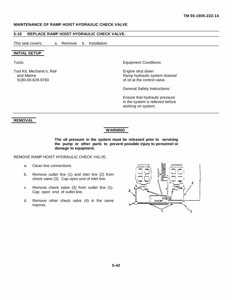
TM 55-1905-222-14
MAINTENANCE OF RAMP HOIST HYDRAULIC CHECK VALVE
5-18 REPLACE RAMP HOIST HYDRAULIC CHECK VALVE.
This task covers: a. Removal b. Installation
INITIAL SETUP
Tools: Equipment Conditions:
Tool Kit, Mechanic's, Rail Engine shut downand Marine Ramp hydraulic system drained5180-00-629-9783 of oil at the control valve.
General Safety Instructions:
Ensure that hydraulic pressurein the system is relieved beforeworking on system.
REMOVAL
WARNING
The oil pressure in the system must be released prior to servicingthe pump or other parts to prevent possible injury to personnel ordamage to equipment.
REMOVE RAMP HOIST HYDRAULIC CHECK VALVE.
a. Clean line connections.
b. Remove outlet line (1) and inlet line (2) fromcheck valve (3). Cap open end of inlet line.
c. Remove check valve (3) from outlet line (1) .Cap open end of outlet line.
d. Remove other check valve (4) in the samemanner.
5-42
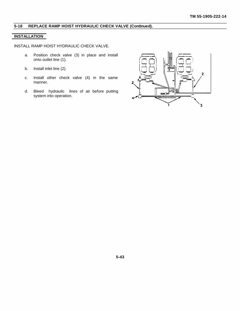
TM 55-1905-222-14
5-18 REPLACE RAMP HOIST HYDRAULIC CHECK VALVE (Continued).
INSTALLATION
INSTALL RAMP HOIST HYDRAULIC CHECK VALVE.
a. Position check valve (3) in place and installonto outlet line (1).
b. Install inlet line (2).
c. Install other check valve (4) in the samemanner.
d. Bleed hydraulic lines of air before puttingsystem into operation.
5-43
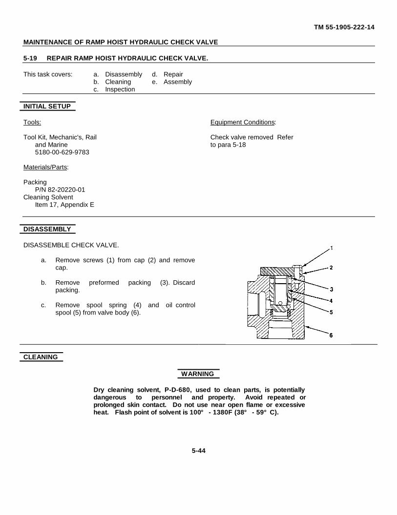
TM 55-1905-222-14
MAINTENANCE OF RAMP HOIST HYDRAULIC CHECK VALVE
5-19 REPAIR RAMP HOIST HYDRAULIC CHECK VALVE.
This task covers: a. Disassembly d. Repairb. Cleaning e. Assemblyc. Inspection
INITIAL SETUP
Tools: Equipment Conditions:
Tool Kit, Mechanic's, Rail Check valve removed Referand Marine to para 5-185180-00-629-9783
Materials/Parts:
PackingP/N 82-20220-01
Cleaning SolventItem 17, Appendix E
DISASSEMBLY
DISASSEMBLE CHECK VALVE.
a. Remove screws (1) from cap (2) and removecap.
b. Remove preformed packing (3). Discardpacking.
c. Remove spool spring (4) and oil controlspool (5) from valve body (6).
CLEANING
WARNING
Dry cleaning solvent, P-D-680, used to clean parts, is potentiallydangerous to personnel and property. Avoid repeated orprolonged skin contact. Do not use near open flame or excessiveheat. Flash point of solvent is 100° - 1380F (38° - 59°C).
5-44
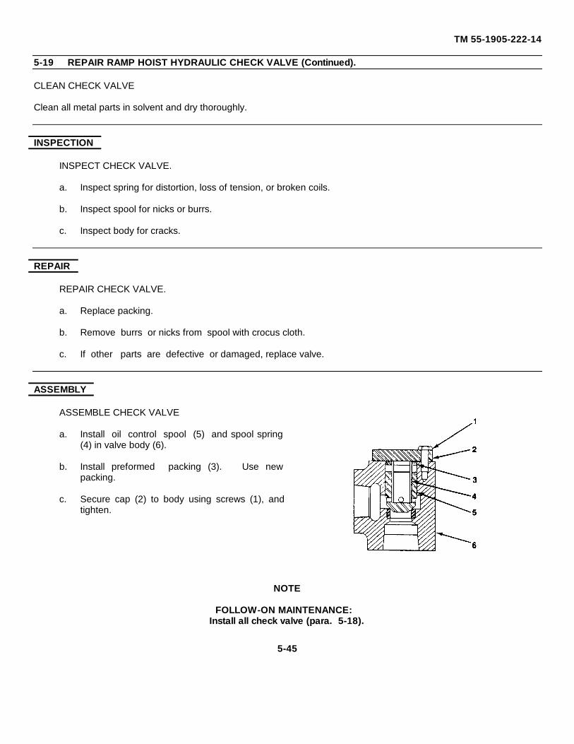
TM 55-1905-222-14
5-19 REPAIR RAMP HOIST HYDRAULIC CHECK VALVE (Continued).
CLEAN CHECK VALVE
Clean all metal parts in solvent and dry thoroughly.
INSPECTION
INSPECT CHECK VALVE.
a. Inspect spring for distortion, loss of tension, or broken coils.
b. Inspect spool for nicks or burrs.
c. Inspect body for cracks.
REPAIR
REPAIR CHECK VALVE.
a. Replace packing.
b. Remove burrs or nicks from spool with crocus cloth.
c. If other parts are defective or damaged, replace valve.
ASSEMBLY
ASSEMBLE CHECK VALVE
a. Install oil control spool (5) and spool spring(4) in valve body (6).
b. Install preformed packing (3). Use newpacking.
c. Secure cap (2) to body using screws (1), andtighten.
NOTE
FOLLOW-ON MAINTENANCE:Install all check valve (para. 5-18).
5-45
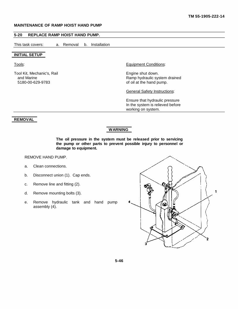
TM 55-1905-222-14
MAINTENANCE OF RAMP HOIST HAND PUMP
5-20 REPLACE RAMP HOIST HAND PUMP.
This task covers: a. Removal b. Installation
INITIAL SETUP
Tools: Equipment Conditions:
Tool Kit, Mechanic's, Rail Engine shut down.and Marine Ramp hydraulic system drained5180-00-629-9783 of oil at the hand pump.
General Safety Instructions:
Ensure that hydraulic pressureIn the system is relieved beforeworking on system.
REMOVAL
WARNING
The oil pressure in the system must be released prior to servicingthe pump or other parts to prevent possible injury to personnel ordamage to equipment.
REMOVE HAND PUMP.
a. Clean connections.
b. Disconnect union (1). Cap ends.
c. Remove line and fitting (2).
d. Remove mounting bolts (3).
e. Remove hydraulic tank and hand pumpassembly (4).
5-46
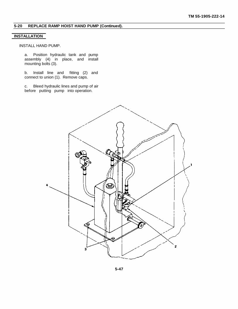
TM 55-1905-222-14
5-20 REPLACE RAMP HOIST HAND PUMP (Continued).
INSTALLATION
INSTALL HAND PUMP.
a. Position hydraulic tank and pumpassembly (4) in place, and installmounting bolts (3).
b. Install line and fitting (2) andconnect to union (1). Remove caps.
c. Bleed hydraulic lines and pump of airbefore putting pump into operation.
5-47
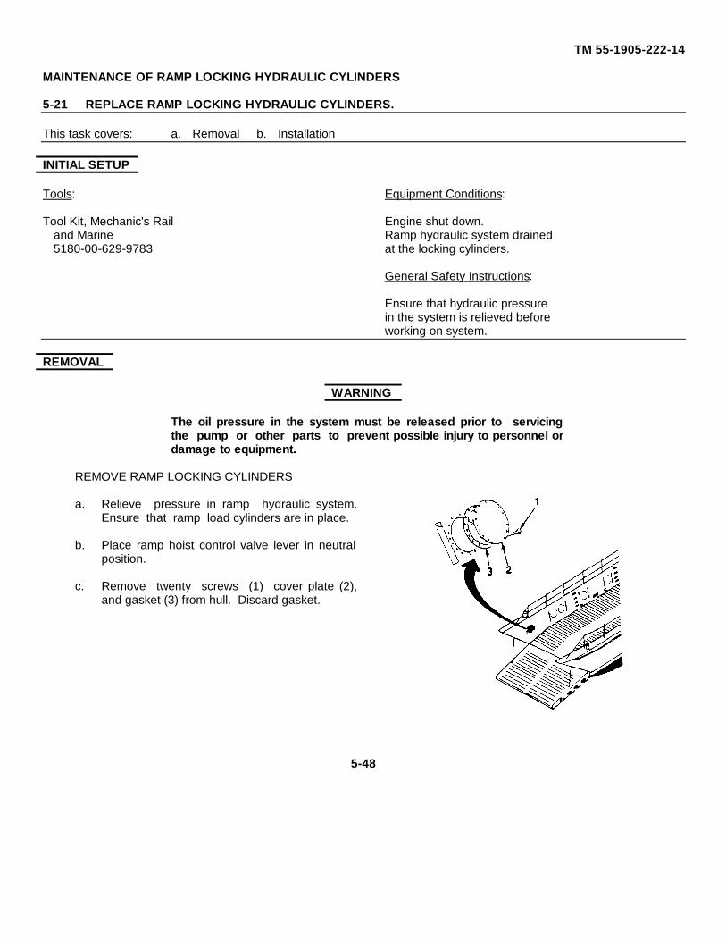
TM 55-1905-222-14
MAINTENANCE OF RAMP LOCKING HYDRAULIC CYLINDERS
5-21 REPLACE RAMP LOCKING HYDRAULIC CYLINDERS.
This task covers: a. Removal b. Installation
INITIAL SETUP
Tools: Equipment Conditions:
Tool Kit, Mechanic's Rail Engine shut down.and Marine Ramp hydraulic system drained5180-00-629-9783 at the locking cylinders.
General Safety Instructions:
Ensure that hydraulic pressurein the system is relieved beforeworking on system.
REMOVAL
WARNING
The oil pressure in the system must be released prior to servicingthe pump or other parts to prevent possible injury to personnel ordamage to equipment.
REMOVE RAMP LOCKING CYLINDERS
a. Relieve pressure in ramp hydraulic system.Ensure that ramp load cylinders are in place.
b. Place ramp hoist control valve lever in neutralposition.
c. Remove twenty screws (1) cover plate (2),and gasket (3) from hull. Discard gasket.
5-48
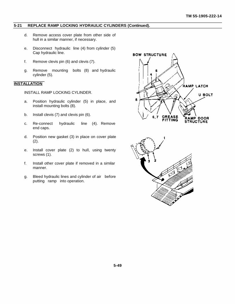
TM 55-1905-222-14
5-21 REPLACE RAMP LOCKING HYDRAULIC CYLINDERS (Continued).
d. Remove access cover plate from other side ofhull in a similar manner, if necessary.
e. Disconnect hydraulic line (4) from cylinder (5)Cap hydraulic line.
f. Remove clevis pin (6) and clevis (7).
g. Remove mounting bolts (8) and hydrauliccylinder (5).
INSTALLATION
INSTALL RAMP LOCKING CYLINDER.
a. Position hydraulic cylinder (5) in place, andinstall mounting bolts (8).
b. Install clevis (7) and clevis pin (6).
c. Re-connect hydraulic line (4). Removeend caps.
d. Position new gasket (3) in place on cover plate(2).
e. Install cover plate (2) to hull, using twentyscrews (1).
f. Install other cover plate if removed in a similarmanner.
g. Bleed hydraulic lines and cylinder of air beforeputting ramp into operation.
5-49
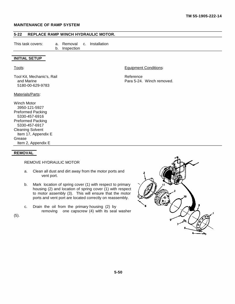
TM 55-1905-222-14
MAINTENANCE OF RAMP SYSTEM
5-22 REPLACE RAMP WINCH HYDRAULIC MOTOR.
This task covers: a. Removal c. Installationb. Inspection
INITIAL SETUP
Tools: Equipment Conditions:
Tool Kit, Mechanic's, Rail Referenceand Marine Para 5-24. Winch removed.5180-00-629-9783
Materials/Parts:
Winch Motor3950-121-5927
Preformed Packing5330-457-6916
Preformed Packing5330-457-6917
Cleaning SolventItem 17, Appendix E
GreaseItem 2, Appendix E
REMOVAL
REMOVE HYDRAULIC MOTOR
a. Clean all dust and dirt away from the motor ports and vent port.
b. Mark location of spring cover (1) with respect to primaryhousing (2) and location of spring cover (1) with respectto motor assembly (3). This will ensure that the motorports and vent port are located correctly on reassembly.
c. Drain the oil from the primary housing (2) by removing one capscrew (4) with its seal washer
(5).
5-50
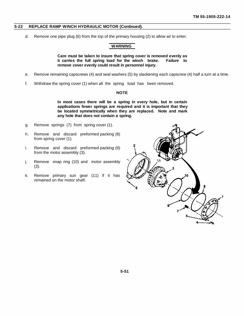
TM 55-1905-222-14
5-22 REPLACE RAMP WINCH HYDRAULIC MOTOR (Continued).
d. Remove one pipe plug (6) from the top of the primary housing (2) to allow air to enter.
WARNING
Care must be taken to insure that spring cover is removed evenly asit carries the full spring load for the winch brake. Failure toremove cover evenly could result in personnel injury.
e. Remove remaining capscrews (4) and seal washers (5) by slackening each capscrew (4) half a turn at a time.
f. Withdraw the spring cover (1) when all the spring load has been removed.
NOTE
In most cases there will be a spring in every hole, but in certainapplications fewer springs are required and it is important that theybe located symmetrically when they are replaced. Note and markany hole that does not contain a spring.
g. Remove springs (7) from spring cover (1).
h. Remove and discard preformed packing (8)from spring cover (1).
i. Remove and discard preformed packing (9)from the motor assembly (3).
j. Remove snap ring (10) and motor assembly(3).
k. Remove primary sun gear (11) if it hasremained on the motor shaft.
5-51
TM 55-1905-222-14
5-22 REPLACE RAMP WINCH HYDRAULIC MOTOR (Continued).
CLEANING
CLEAN ALL REMOVED PARTS.
WARNING
Dry cleaning solvent, P-D-680, used to clean parts, is potentiallydangerous to personnel and property. Avoid repeated orprolonged skin contact. Do not use near open flame or excessiveheat. Flash point of solvent is 100° - 138°F (38° - 59°C).
a. Wash all parts in cleaning solvent P-D-680.
b. Dry thoroughly with compressed air or cleanwith lint-free cloths.
INSPECTION
INSPECT ALL REMOVED PARTS
a. Inspect and discard all preformed packings.Get replacement packings.
b. Inspect the base in the spring cover forscores or bruises. Smooth out defects witha scraper and extra fine emery cloth inorder that preformed packing will sealeffectively.
c. Check snap ring for flatness and that itforms a true circle. Replace if bent or damaged.
5-52
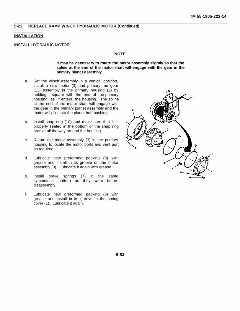
TM 55-1905-222-14
5-22 REPLACE RAMP WINCH HYDRAULIC MOTOR (Continued).
INSTALLATION
INSTALL HYDRAULIC MOTOR.
NOTE
It may be necessary to rotate the motor assembly slightly so that thespline at the end of the motor shaft will engage with the gear in theprimary planet assembly.
a. Set the winch assembly in a vertical position,install a new motor (3) and primary run gear(11) assembly in the primary housing (2) byholding it square with the end of the primaryhousing as it enters the housing. The splineat the end of the motor shaft will engage withthe gear in the primary planet assembly and themotor will pilot into the planet hub bushing.
b. Install snap ring (10) and make sure that it isproperly seated in the bottom of the snap ringgroove all the way around the housing.
c. Rotate the motor assembly (3) in the primaryhousing to locate the motor ports and vent portas required.
d. Lubricate new preformed packing (9) withgrease and install in its groove on the motorassembly (3) Lubricate it again with grease.
e. Install brake springs (7) in the samesymmetrical pattern as they were beforedisassembly.
f. Lubricate new preformed packing (8) withgrease and install in its groove in the springcover (1). Lubricate it again.
5-53
TM 55-1905-222-14
5-22 REPLACE RAMP WINCH HYDRAULIC MOTOR (Continued).
g. Install spring cover (1) over themotor assembly (3) so that the ventport is located in the correctposition as required.
h. Install capscrews (4) and sealwashers (5). Tighten evenly makingsure that the spring cover (1)remains parallel to the end of theprimary housing as it is tightened intoplace. Torque the capscrews to 50pounds foot.
5-23 REPAIR RAMP WINCH HYDRAULIC MOTOR.
This task covers: a. Disassembly c. Inspectionb. Cleaning d. Assembly
INITIAL SETUP
Tools: Equipment Conditions:
Tool Kit, Mechanic's Rail Referencesand Marine Para 5-24 Winch removed5180-00-629-9783 Para 5-22 Winch motor removedBearing Puller
Materials/Parts: Materials/Parts:
Cleaning Solvent Backup WasherItem 17, Appendix E P/N 50362 (2)
Grease Backup WasherItem 2, Appendix E P/N 50487 (4)
'O' Ring Backup WasherP/N 50306 (2) P/N 50368
'O' Ring Backup WasherP/N 50488 (2) P/N 50367
'O' Ring Medium Pocket SealP/N 50332 (2) P/N 50485 (4)'O' Ring Large Pocket SealP/N 50339 P/N 50486 (8)'O' Ring Small Pocket SealP/N 50337 P/N 50484 (8)
5-54
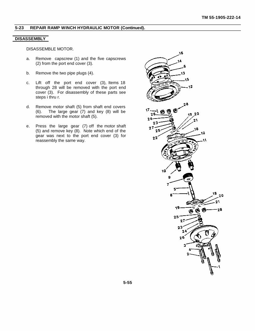
TM 55-1905-222-14
5-23 REPAIR RAMP WINCH HYDRAULIC MOTOR (Continued).
DISASSEMBLY
DISASSEMBLE MOTOR.
a. Remove capscrew (1) and the five capscrews(2) from the port end cover (3).
b. Remove the two pipe plugs (4).
c. Lift off the port end cover (3), Items 18through 28 will be removed with the port endcover (3). For disassembly of these parts seesteps i thru r.
d. Remove motor shaft (5) from shaft end covers(6). The large gear (7) and key (8) will beremoved with the motor shaft (5).
e. Press the large gear (7) off the motor shaft(5) and remove key (8). Note which end of thegear was next to the port end cover (3) forreassembly the same way.
5-55
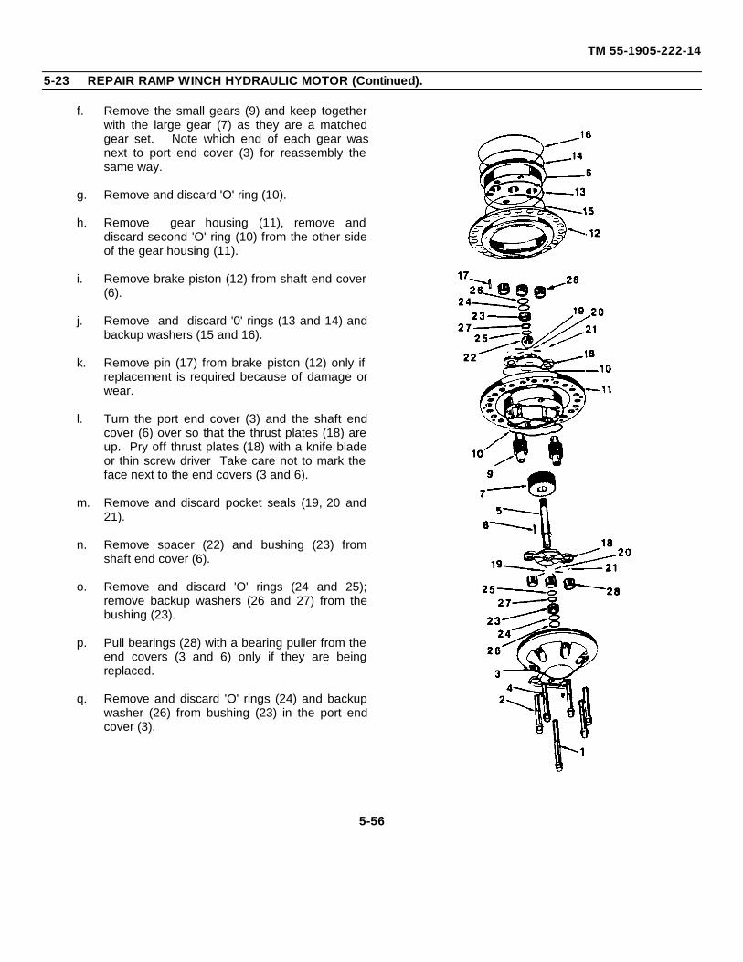
TM 55-1905-222-14
5-23 REPAIR RAMP WINCH HYDRAULIC MOTOR (Continued).
f. Remove the small gears (9) and keep togetherwith the large gear (7) as they are a matchedgear set. Note which end of each gear wasnext to port end cover (3) for reassembly thesame way.
g. Remove and discard 'O' ring (10).
h. Remove gear housing (11), remove anddiscard second 'O' ring (10) from the other sideof the gear housing (11).
i. Remove brake piston (12) from shaft end cover(6).
j. Remove and discard '0' rings (13 and 14) andbackup washers (15 and 16).
k. Remove pin (17) from brake piston (12) only ifreplacement is required because of damage orwear.
l. Turn the port end cover (3) and the shaft endcover (6) over so that the thrust plates (18) areup. Pry off thrust plates (18) with a knife bladeor thin screw driver Take care not to mark theface next to the end covers (3 and 6).
m. Remove and discard pocket seals (19, 20 and21).
n. Remove spacer (22) and bushing (23) fromshaft end cover (6).
o. Remove and discard 'O' rings (24 and 25);remove backup washers (26 and 27) from thebushing (23).
p. Pull bearings (28) with a bearing puller from theend covers (3 and 6) only if they are beingreplaced.
q. Remove and discard 'O' rings (24) and backupwasher (26) from bushing (23) in the port endcover (3).
5-56
TM 55-1905-222-14
5-23 REPAIR RAMP WINCH HYDRAULIC MOTOR (Continued).
r. If bearings (28) have been removed, remove bushing (23) from the port end cover (3).
CLEANING
CLEAN MOTOR PARTS
a. Clean thrust plates with a cleanlint-free cloth. Never wash thethrust plates.
WARNING
Dry cleaning solvent, P-D-680, used to clean parts, is potentiallydangerous to personnel and property. Avoid repeated orprolonged skin contact. Do not use near open flame or excessiveheat. Flash point of solvent is 100° - 138°F (38° - 59°C).
b. Clean all other motor parts insolvent P-D-680 Dry thoroughlywith compressed air or clean withlint-free cloths.
c. Allow bearings to air dry aftercleaning in solvent P-D-680. Do notdry with compressed air.
INSPECTION
INSPECT MOTOR PARTS
a. Inspect and discard all 'O' rings,backup washers and pocket seals andget replacements.
b. Inspect needle bearings for freenessof rollers. Check for pits, brokenrollers or excessive wear and replaceif any of these conditions exist.
c. Inspect gears, check the edges ofthe gear teeth and faces for scoring orroughness. Remove roughness orscoring with a fine hone.
5-57
TM 55-1905-222-14
5-23 REPAIR RAMP WINCH HYDRAULIC MOTOR (Continued).
d. Inspect the gear hubs for excessivewear at bearing points. if wearexceeds 0.001 inch on the hubdiameter, the gears should bereplaced. Replace gears in setssince they are matched at the time ofmanufacture.
e. Inspect the machined surfaces of theport end cover, shaft end cover andgear housing for roughness. Stoneto remove roughness. Replace ifroughness is excessive.
f. Measure the gear housing bore andreplace if the radial wear is in excessof 0.006. A new gear housingmeasures 2.0025 inch in the smallbores and 3.7525 inch in the largebore.
g. Inspect thrust plates for erosion orexcessive wear on the runningsurfaces. Replace if necessary.
h. Rewash all parts that have beenstoned and dry thoroughly.
i. Inspect shaft for distortion.Repair/replace as necessary.
NOTE
If either the gears (13) or needle bearings (27) are replaced becauseof excessive wear, it is good practice to replace both the gears andbearings. Replacement of one part and not the other will causepremature wear of the new part because of its attempt to conform tothe wear pattern of the old part. Also if the gears and bearings arereplaced due to excessive wear, carefully check the side of the gearhousing bore which has most wear. In most cases the gear housingwill also have to be replaced along with the gears and bearings.
5-58
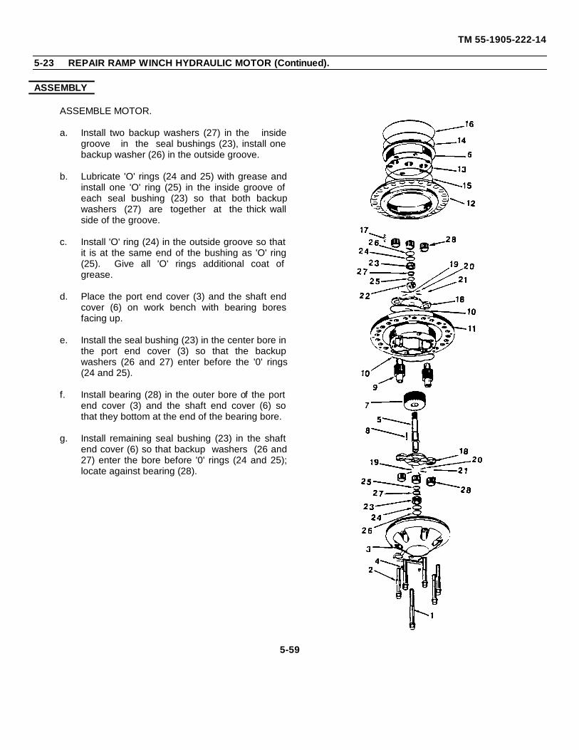
TM 55-1905-222-14
5-23 REPAIR RAMP WINCH HYDRAULIC MOTOR (Continued).
ASSEMBLY
ASSEMBLE MOTOR.
a. Install two backup washers (27) in the insidegroove in the seal bushings (23), install onebackup washer (26) in the outside groove.
b. Lubricate 'O' rings (24 and 25) with grease andinstall one 'O' ring (25) in the inside groove ofeach seal bushing (23) so that both backupwashers (27) are together at the thick wallside of the groove.
c. Install 'O' ring (24) in the outside groove so thatit is at the same end of the bushing as 'O' ring(25). Give all 'O' rings additional coat ofgrease.
d. Place the port end cover (3) and the shaft endcover (6) on work bench with bearing boresfacing up.
e. Install the seal bushing (23) in the center bore inthe port end cover (3) so that the backupwashers (26 and 27) enter before the '0' rings(24 and 25).
f. Install bearing (28) in the outer bore of the portend cover (3) and the shaft end cover (6) sothat they bottom at the end of the bearing bore.
g. Install remaining seal bushing (23) in the shaftend cover (6) so that backup washers (26 and27) enter the bore before '0' rings (24 and 25);locate against bearing (28).
5-59
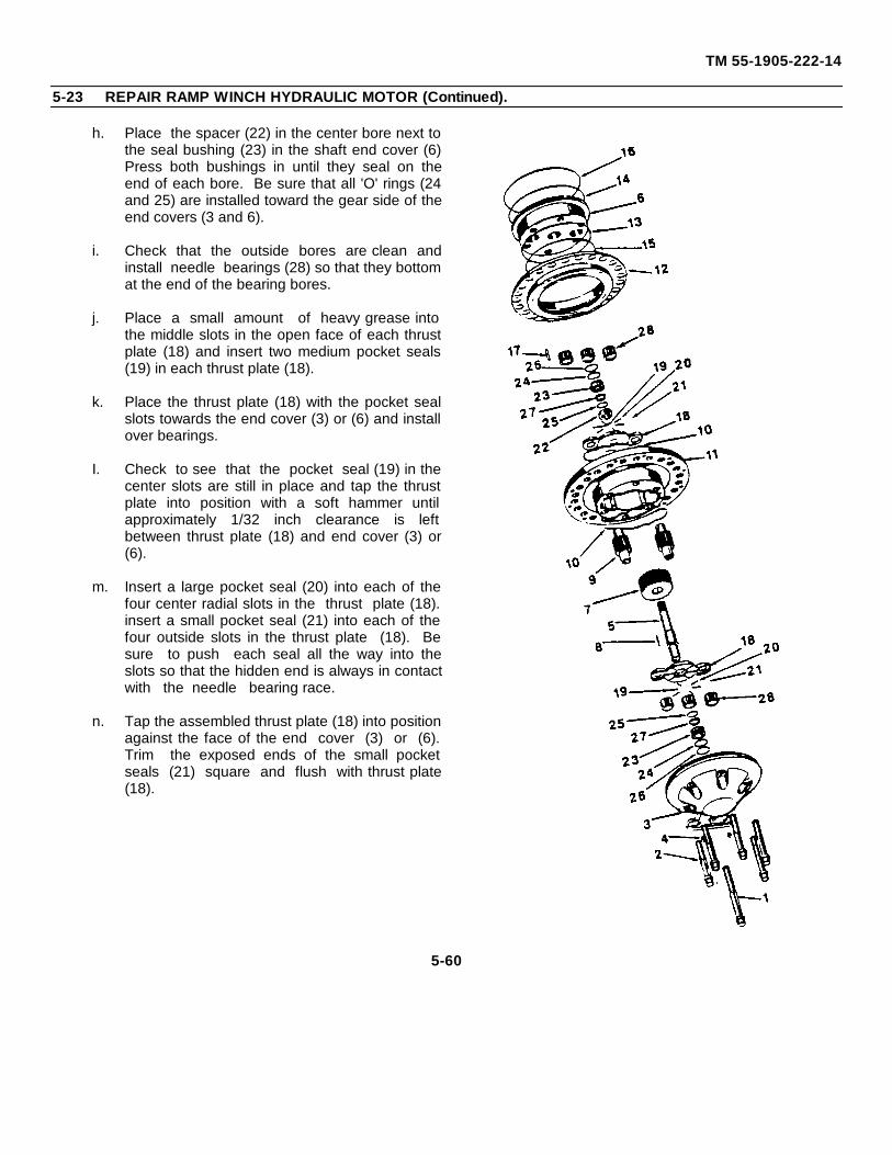
TM 55-1905-222-14
5-23 REPAIR RAMP WINCH HYDRAULIC MOTOR (Continued).
h. Place the spacer (22) in the center bore next tothe seal bushing (23) in the shaft end cover (6)Press both bushings in until they seal on theend of each bore. Be sure that all 'O' rings (24and 25) are installed toward the gear side of theend covers (3 and 6).
i. Check that the outside bores are clean andinstall needle bearings (28) so that they bottomat the end of the bearing bores.
j. Place a small amount of heavy grease intothe middle slots in the open face of each thrustplate (18) and insert two medium pocket seals(19) in each thrust plate (18).
k. Place the thrust plate (18) with the pocket sealslots towards the end cover (3) or (6) and installover bearings.
I. Check to see that the pocket seal (19) in thecenter slots are still in place and tap the thrustplate into position with a soft hammer untilapproximately 1/32 inch clearance is leftbetween thrust plate (18) and end cover (3) or(6).
m. Insert a large pocket seal (20) into each of thefour center radial slots in the thrust plate (18).insert a small pocket seal (21) into each of thefour outside slots in the thrust plate (18). Besure to push each seal all the way into theslots so that the hidden end is always in contactwith the needle bearing race.
n. Tap the assembled thrust plate (18) into positionagainst the face of the end cover (3) or (6).Trim the exposed ends of the small pocketseals (21) square and flush with thrust plate(18).
5-60
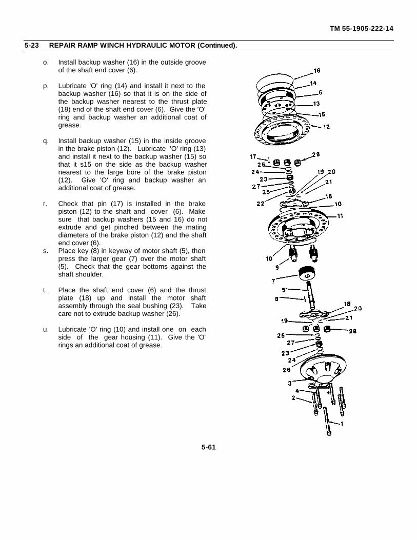
TM 55-1905-222-14
5-23 REPAIR RAMP WINCH HYDRAULIC MOTOR (Continued).
o. Install backup washer (16) in the outside grooveof the shaft end cover (6).
p. Lubricate 'O' ring (14) and install it next to thebackup washer (16) so that it is on the side ofthe backup washer nearest to the thrust plate(18) end of the shaft end cover (6). Give the 'O'ring and backup washer an additional coat ofgrease.
q. Install backup washer (15) in the inside groovein the brake piston (12). Lubricate 'O' ring (13)and install it next to the backup washer (15) sothat it s15 on the side as the backup washernearest to the large bore of the brake piston(12). Give 'O' ring and backup washer anadditional coat of grease.
r. Check that pin (17) is installed in the brakepiston (12) to the shaft and cover (6). Makesure that backup washers (15 and 16) do notextrude and get pinched between the matingdiameters of the brake piston (12) and the shaftend cover (6).
s. Place key (8) in keyway of motor shaft (5), thenpress the larger gear (7) over the motor shaft(5). Check that the gear bottoms against theshaft shoulder.
t. Place the shaft end cover (6) and the thrustplate (18) up and install the motor shaftassembly through the seal bushing (23). Takecare not to extrude backup washer (26).
u. Lubricate 'O' ring (10) and install one on eachside of the gear housing (11). Give the 'O'rings an additional coat of grease.
5-61
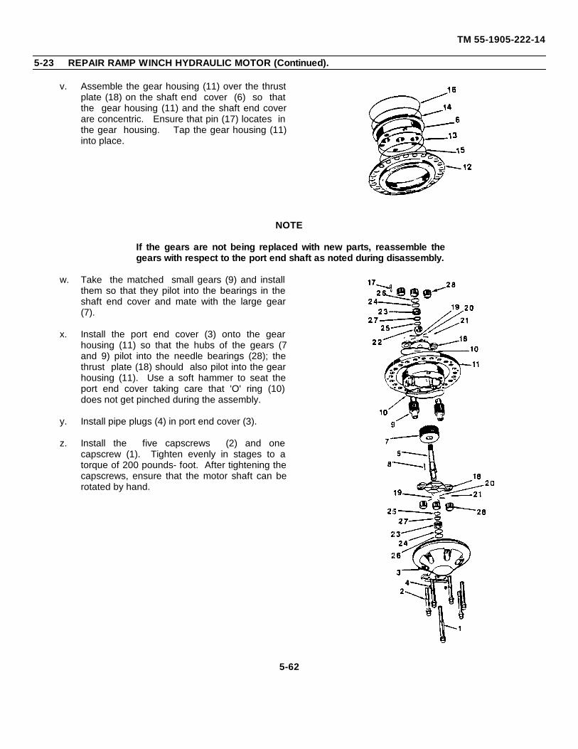
TM 55-1905-222-14
5-23 REPAIR RAMP WINCH HYDRAULIC MOTOR (Continued).
v. Assemble the gear housing (11) over the thrustplate (18) on the shaft end cover (6) so thatthe gear housing (11) and the shaft end coverare concentric. Ensure that pin (17) locates inthe gear housing. Tap the gear housing (11)into place.
NOTE
If the gears are not being replaced with new parts, reassemble thegears with respect to the port end shaft as noted during disassembly.
w. Take the matched small gears (9) and installthem so that they pilot into the bearings in theshaft end cover and mate with the large gear(7).
x. Install the port end cover (3) onto the gearhousing (11) so that the hubs of the gears (7and 9) pilot into the needle bearings (28); thethrust plate (18) should also pilot into the gearhousing (11). Use a soft hammer to seat theport end cover taking care that 'O' ring (10)does not get pinched during the assembly.
y. Install pipe plugs (4) in port end cover (3).
z. Install the five capscrews (2) and onecapscrew (1). Tighten evenly in stages to atorque of 200 pounds- foot. After tightening thecapscrews, ensure that the motor shaft can berotated by hand.
5-62
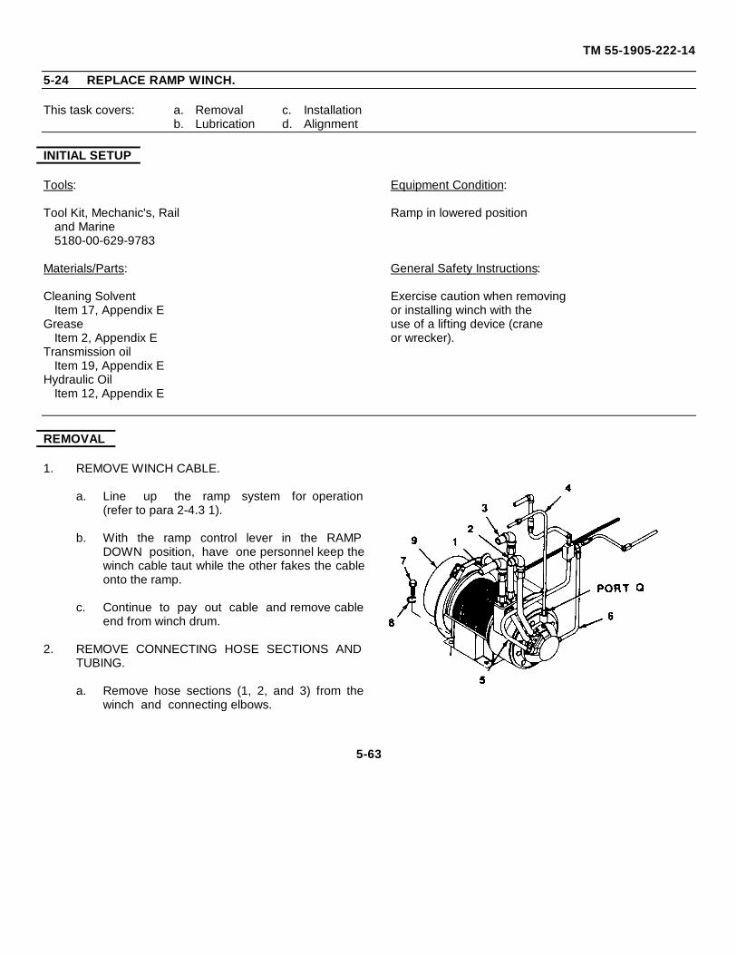
TM 55-1905-222-14
5-24 REPLACE RAMP WINCH.
This task covers: a. Removal c. Installationb. Lubrication d. Alignment
INITIAL SETUP
Tools: Equipment Condition:
Tool Kit, Mechanic's, Rail Ramp in lowered positionand Marine5180-00-629-9783
Materials/Parts: General Safety Instructions:
Cleaning Solvent Exercise caution when removingItem 17, Appendix E or installing winch with the
Grease use of a lifting device (craneItem 2, Appendix E or wrecker).
Transmission oilItem 19, Appendix E
Hydraulic OilItem 12, Appendix E
REMOVAL
1. REMOVE WINCH CABLE.
a. Line up the ramp system for operation(refer to para 2-4.3 1).
b. With the ramp control lever in the RAMPDOWN position, have one personnel keep thewinch cable taut while the other fakes the cableonto the ramp.
c. Continue to pay out cable and remove cableend from winch drum.
2. REMOVE CONNECTING HOSE SECTIONS ANDTUBING.
a. Remove hose sections (1, 2, and 3) from thewinch and connecting elbows.
5-63
TM 55-1905-222-14
5-24 REPLACE RAMP WINCH (Continued).
b. Remove tubing (4) - (drain line toreservoir) from the winch port Q.
c. Remove hose sections (5 and 6) frommotor port and brake portrespectively.
3. REMOVE WINCH FROM FOUNDATION.
WARNING
Total weight of winch is 1,070 lbs (484.710 kg). Be sure that asuitable lifting device is available prior to removing winch from hull.Failure to use a lifting device could result ill injury to personnel.
a. Remove mounting bolts (7) andlockwashers (8) in four places.
b. Use suitable lifting device to removewinch (9) from foundation.
LUBRICATION
LUBRICATE REPLACEMENT WINCH.
a. Remove filler plug on final driveassembly and fill with SAE 90transmission oil to the level of the fillerplug. Install filler plug.
b. Fill primary drive assembly withhydraulic oil MIL-L-17672 through portQ.
c. Apply two or three shots of grease to thegrease fittings on the end of auto-reverse mechanism lever arm.
5-64
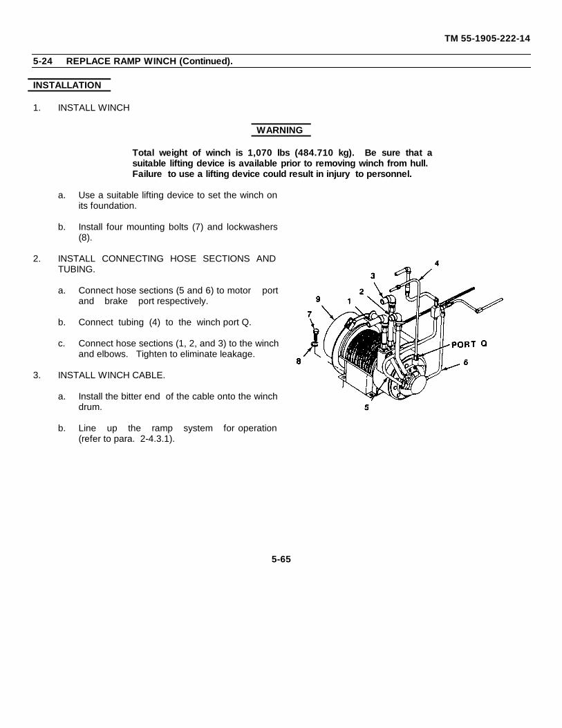
TM 55-1905-222-14
5-24 REPLACE RAMP WINCH (Continued).
INSTALLATION
1. INSTALL WINCH
WARNING
Total weight of winch is 1,070 lbs (484.710 kg). Be sure that asuitable lifting device is available prior to removing winch from hull.Failure to use a lifting device could result in injury to personnel.
a. Use a suitable lifting device to set the winch onits foundation.
b. Install four mounting bolts (7) and lockwashers(8).
2. INSTALL CONNECTING HOSE SECTIONS ANDTUBING.
a. Connect hose sections (5 and 6) to motor portand brake port respectively.
b. Connect tubing (4) to the winch port Q.
c. Connect hose sections (1, 2, and 3) to the winchand elbows. Tighten to eliminate leakage.
3. INSTALL WINCH CABLE.
a. Install the bitter end of the cable onto the winchdrum.
b. Line up the ramp system for operation(refer to para. 2-4.3.1).
5-65
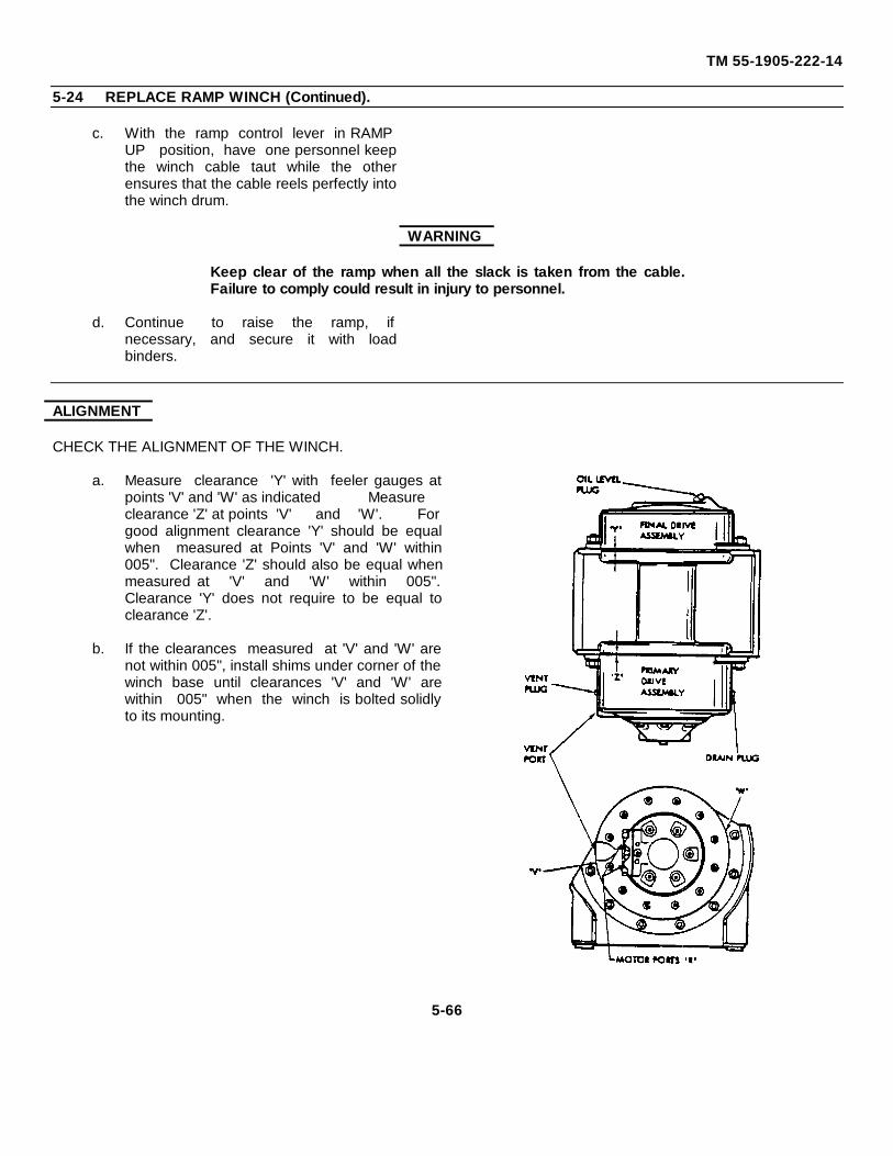
TM 55-1905-222-14
5-24 REPLACE RAMP WINCH (Continued).
c. With the ramp control lever in RAMPUP position, have one personnel keepthe winch cable taut while the otherensures that the cable reels perfectly intothe winch drum.
WARNING
Keep clear of the ramp when all the slack is taken from the cable.Failure to comply could result in injury to personnel.
d. Continue to raise the ramp, ifnecessary, and secure it with loadbinders.
ALIGNMENT
CHECK THE ALIGNMENT OF THE WINCH.
a. Measure clearance 'Y' with feeler gauges atpoints 'V' and 'W' as indicated Measureclearance 'Z' at points 'V' and 'W'. Forgood alignment clearance 'Y' should be equalwhen measured at Points 'V' and 'W' within005". Clearance 'Z' should also be equal whenmeasured at 'V' and 'W' within 005".Clearance 'Y' does not require to be equal toclearance 'Z'.
b. If the clearances measured at 'V' and 'W' arenot within 005", install shims under corner of thewinch base until clearances 'V' and 'W' arewithin 005" when the winch is bolted solidlyto its mounting.
5-66
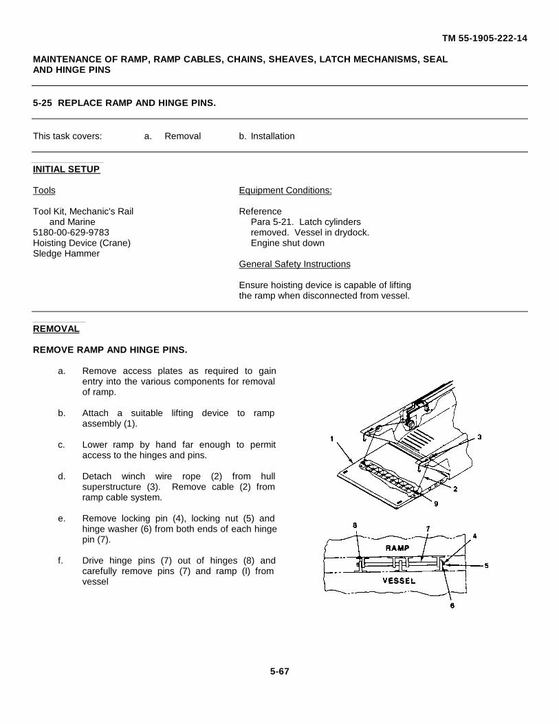
TM 55-1905-222-14
MAINTENANCE OF RAMP, RAMP CABLES, CHAINS, SHEAVES, LATCH MECHANISMS, SEALAND HINGE PINS
5-25 REPLACE RAMP AND HINGE PINS.
This task covers: a. Removal b. Installation
INITIAL SETUP
Tools Equipment Conditions:
Tool Kit, Mechanic's Rail Referenceand Marine Para 5-21. Latch cylinders
5180-00-629-9783 removed. Vessel in drydock.Hoisting Device (Crane) Engine shut downSledge Hammer
General Safety Instructions
Ensure hoisting device is capable of liftingthe ramp when disconnected from vessel.
REMOVAL
REMOVE RAMP AND HINGE PINS.
a. Remove access plates as required to gainentry into the various components for removalof ramp.
b. Attach a suitable lifting device to rampassembly (1).
c. Lower ramp by hand far enough to permitaccess to the hinges and pins.
d. Detach winch wire rope (2) from hullsuperstructure (3). Remove cable (2) fromramp cable system.
e. Remove locking pin (4), locking nut (5) andhinge washer (6) from both ends of each hingepin (7).
f. Drive hinge pins (7) out of hinges (8) andcarefully remove pins (7) and ramp (I) fromvessel
5-67
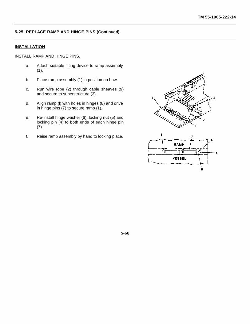
TM 55-1905-222-14
5-25 REPLACE RAMP AND HINGE PINS (Continued).
INSTALLATION
INSTALL RAMP AND HINGE PINS.
a. Attach suitable lifting device to ramp assembly(1).
b. Place ramp assembly (1) in position on bow.
c. Run wire rope (2) through cable sheaves (9)and secure to superstructure (3).
d. Align ramp (l) with holes in hinges (8) and drivein hinge pins (7) to secure ramp (1).
e. Re-install hinge washer (6), locking nut (5) andlocking pin (4) to both ends of each hinge pin(7).
f. Raise ramp assembly by hand to locking place.
5-68
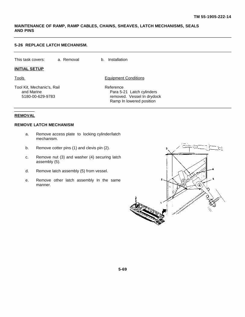
TM 55-1905-222-14
MAINTENANCE OF RAMP, RAMP CABLES, CHAINS, SHEAVES, LATCH MECHANISMS, SEALSAND PINS
5-26 REPLACE LATCH MECHANISM.
This task covers: a. Removal b. Installation
INITIAL SETUP
Tools Equipment Conditions
Tool Kit, Mechanic's, Rail Referenceand Marine Para 5-21 Latch cylinders5180-00-629-9783 removed. Vessel In drydock
Ramp In lowered position
REMOVAL
REMOVE LATCH MECHANISM
a. Remove access plate to locking cylinder/latchmechanism.
b. Remove cotter pins (1) and clevis pin (2).
c. Remove nut (3) and washer (4) securing latchassembly (5).
d. Remove latch assembly (5) from vessel.
e. Remove other latch assembly In the samemanner.
5-69
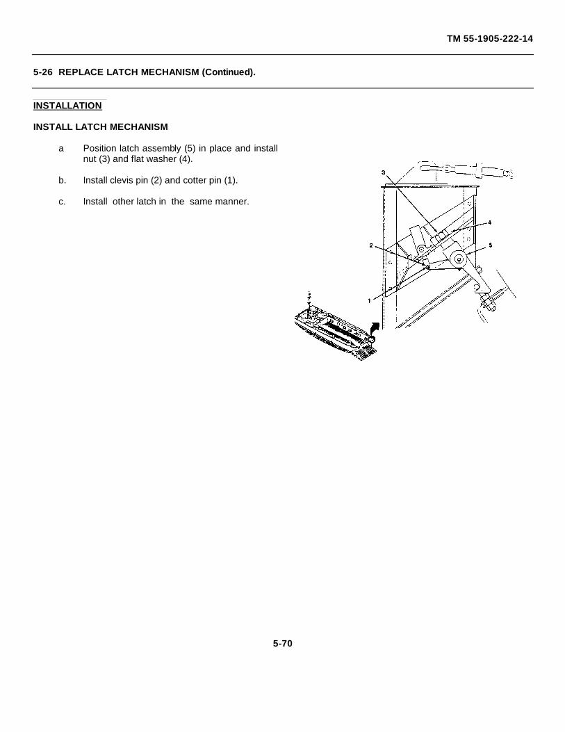
TM 55-1905-222-14
5-26 REPLACE LATCH MECHANISM (Continued).
INSTALLATION
INSTALL LATCH MECHANISM
a Position latch assembly (5) in place and installnut (3) and flat washer (4).
b. Install clevis pin (2) and cotter pin (1).
c. Install other latch in the same manner.
5-70
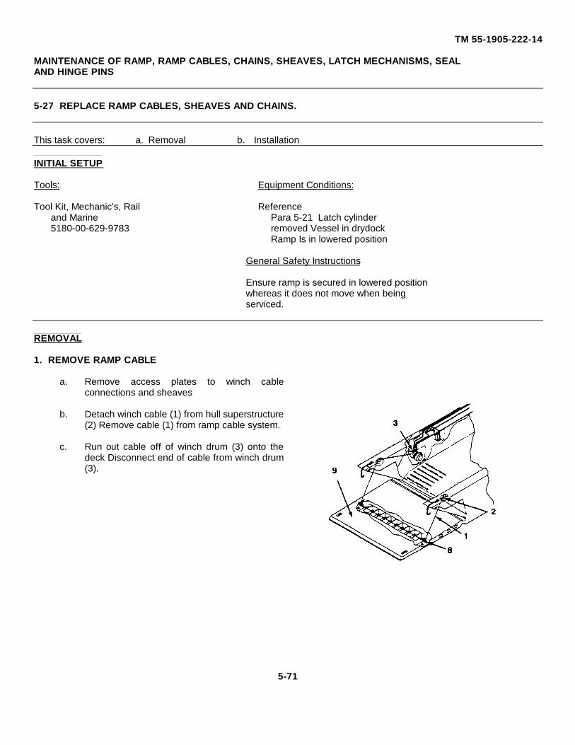
TM 55-1905-222-14
MAINTENANCE OF RAMP, RAMP CABLES, CHAINS, SHEAVES, LATCH MECHANISMS, SEALAND HINGE PINS
5-27 REPLACE RAMP CABLES, SHEAVES AND CHAINS.
This task covers: a. Removal b. Installation
INITIAL SETUP
Tools: Equipment Conditions:
Tool Kit, Mechanic's, Rail Referenceand Marine Para 5-21 Latch cylinder5180-00-629-9783 removed Vessel in drydock
Ramp Is in lowered position
General Safety Instructions
Ensure ramp is secured in lowered positionwhereas it does not move when beingserviced.
REMOVAL
1. REMOVE RAMP CABLE
a. Remove access plates to winch cableconnections and sheaves
b. Detach winch cable (1) from hull superstructure(2) Remove cable (1) from ramp cable system.
c. Run out cable off of winch drum (3) onto thedeck Disconnect end of cable from winch drum(3).
5-71
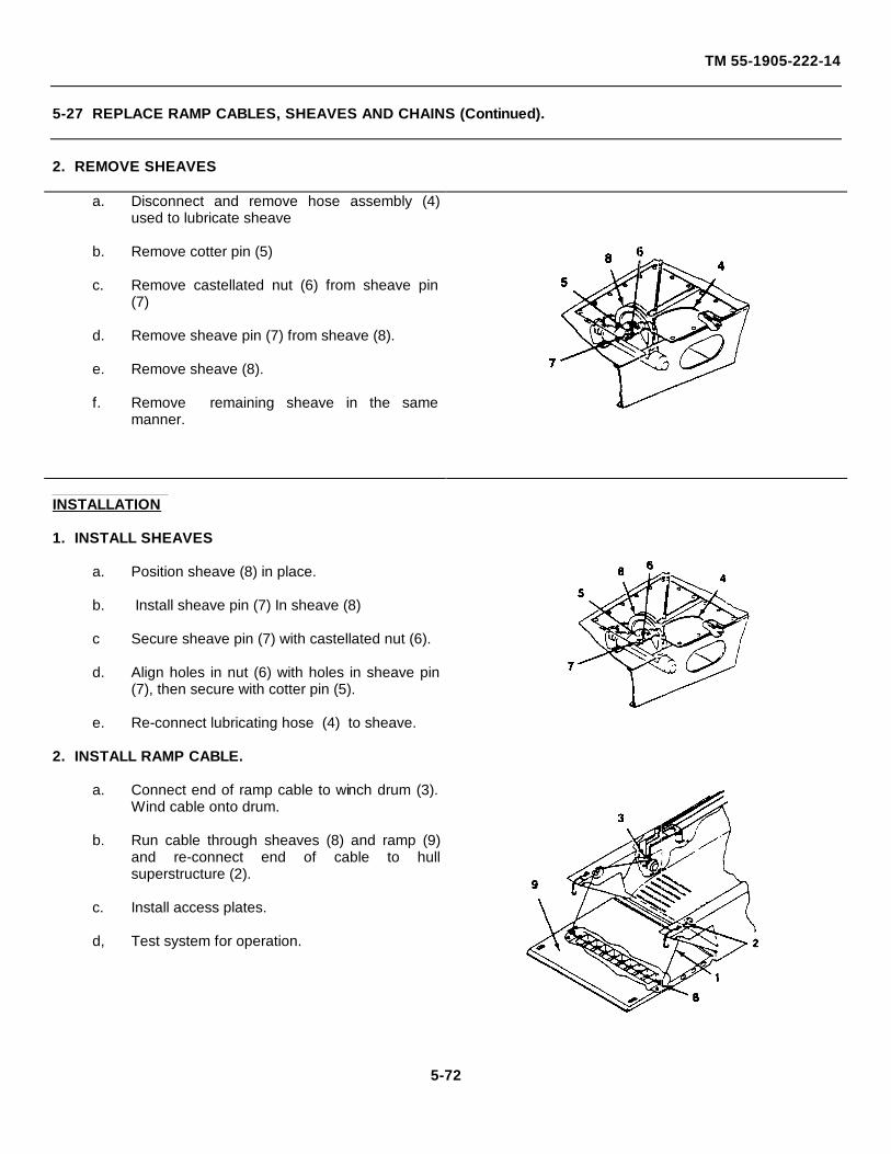
TM 55-1905-222-14
5-27 REPLACE RAMP CABLES, SHEAVES AND CHAINS (Continued).
2. REMOVE SHEAVES
a. Disconnect and remove hose assembly (4)used to lubricate sheave
b. Remove cotter pin (5)
c. Remove castellated nut (6) from sheave pin(7)
d. Remove sheave pin (7) from sheave (8).
e. Remove sheave (8).
f. Remove remaining sheave in the samemanner.
INSTALLATION
1. INSTALL SHEAVES
a. Position sheave (8) in place.
b. Install sheave pin (7) In sheave (8)
c Secure sheave pin (7) with castellated nut (6).
d. Align holes in nut (6) with holes in sheave pin(7), then secure with cotter pin (5).
e. Re-connect lubricating hose (4) to sheave.
2. INSTALL RAMP CABLE.
a. Connect end of ramp cable to winch drum (3).Wind cable onto drum.
b. Run cable through sheaves (8) and ramp (9)and re-connect end of cable to hullsuperstructure (2).
c. Install access plates.
d, Test system for operation.
5-72
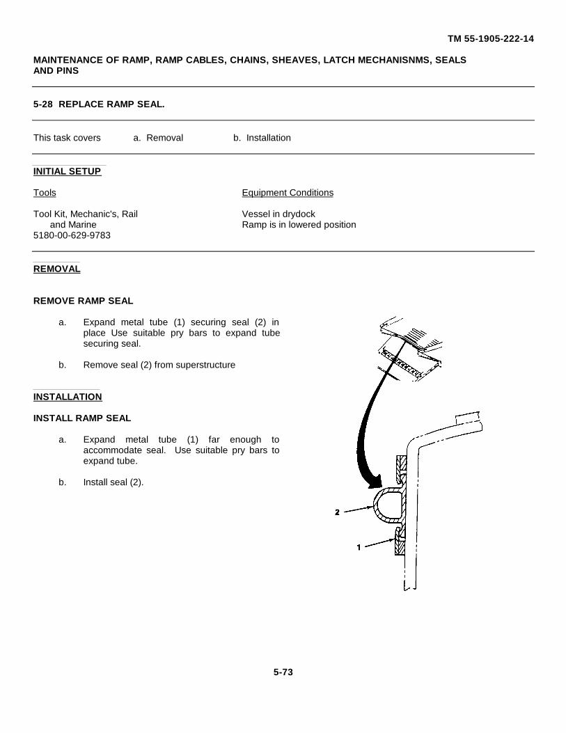
TM 55-1905-222-14
MAINTENANCE OF RAMP, RAMP CABLES, CHAINS, SHEAVES, LATCH MECHANISNMS, SEALSAND PINS
5-28 REPLACE RAMP SEAL.
This task covers a. Removal b. Installation
INITIAL SETUP
Tools Equipment Conditions
Tool Kit, Mechanic's, Rail Vessel in drydockand Marine Ramp is in lowered position
5180-00-629-9783
REMOVAL
REMOVE RAMP SEAL
a. Expand metal tube (1) securing seal (2) inplace Use suitable pry bars to expand tubesecuring seal.
b. Remove seal (2) from superstructure
INSTALLATION
INSTALL RAMP SEAL
a. Expand metal tube (1) far enough toaccommodate seal. Use suitable pry bars toexpand tube.
b. Install seal (2).
5-73
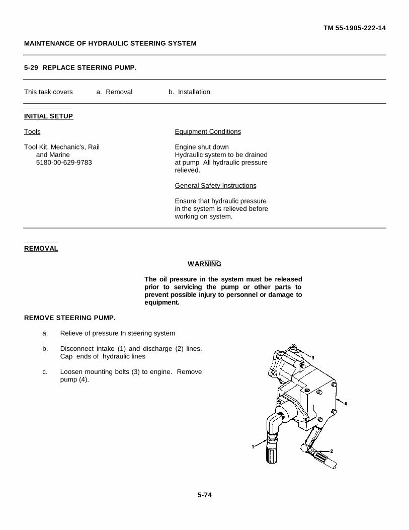
TM 55-1905-222-14
MAINTENANCE OF HYDRAULIC STEERING SYSTEM
5-29 REPLACE STEERING PUMP.
This task covers a. Removal b. Installation
INITIAL SETUP
Tools Equipment Conditions
Tool Kit, Mechanic's, Rail Engine shut downand Marine Hydraulic system to be drained5180-00-629-9783 at pump All hydraulic pressure
relieved.
General Safety Instructions
Ensure that hydraulic pressurein the system is relieved beforeworking on system.
REMOVAL
WARNING
The oil pressure in the system must be releasedprior to servicing the pump or other parts toprevent possible injury to personnel or damage toequipment.
REMOVE STEERING PUMP.
a. Relieve of pressure In steering system
b. Disconnect intake (1) and discharge (2) lines.Cap ends of hydraulic lines
c. Loosen mounting bolts (3) to engine. Removepump (4).
5-74
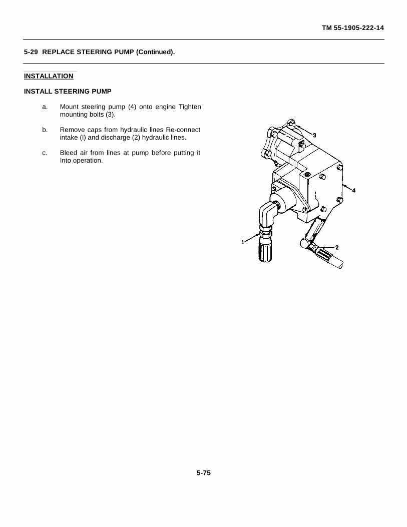
TM 55-1905-222-14
5-29 REPLACE STEERING PUMP (Continued).
INSTALLATION
INSTALL STEERING PUMP
a. Mount steering pump (4) onto engine Tightenmounting bolts (3).
b. Remove caps from hydraulic lines Re-connectintake (I) and discharge (2) hydraulic lines.
c. Bleed air from lines at pump before putting itInto operation.
5-75
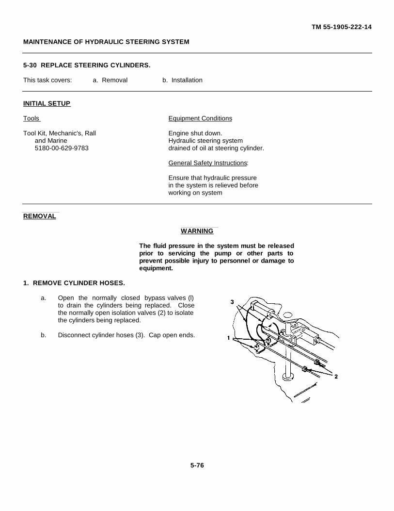
TM 55-1905-222-14
MAINTENANCE OF HYDRAULIC STEERING SYSTEM
5-30 REPLACE STEERING CYLINDERS.
This task covers: a. Removal b. Installation
INITIAL SETUP
Tools Equipment Conditions
Tool Kit, Mechanic's, Rall Engine shut down.and Marine Hydraulic steering system5180-00-629-9783 drained of oil at steering cylinder.
General Safety Instructions:
Ensure that hydraulic pressurein the system is relieved beforeworking on system
REMOVAL
WARNING
The fluid pressure in the system must be releasedprior to servicing the pump or other parts toprevent possible injury to personnel or damage toequipment.
1. REMOVE CYLINDER HOSES.
a. Open the normally closed bypass valves (l)to drain the cylinders being replaced. Closethe normally open isolation valves (2) to isolatethe cylinders being replaced.
b. Disconnect cylinder hoses (3). Cap open ends.
5-76
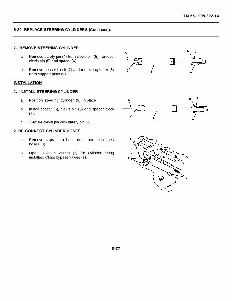
TM 55-1905-222-14
5-30 REPLACE STEERING CYLINDERS (Continued).
2. REMOVE STEERING CYLINDER
a. Remove safety pin (4) from clevis pin (5), removeclevis pin (5) and spacer (6).
b. Remove spacer block (7) and remove cylinder (8)from support plate (9)
INSTALLATION
1. INSTALL STEERING CYLINDER
a. Position steering cylinder (8) in place
b. Install spacer (6), clevis pin (5) and spacer block(7).
c. Secure clevis pin with safety pin (4).
2 RE-CONNECT CYLINDER HOSES.
a. Remove caps from hose ends and re-connecthoses (3).
b. Open isolation valves (2) for cylinder beinginstalled. Close bypass valves (1).
5-77
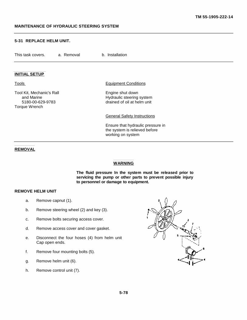
TM 55-1905-222-14
MAINTENANCE OF HYDRAULIC STEERING SYSTEM
5-31 REPLACE HELM UNIT.
This task covers. a. Removal b. Installation
INITIAL SETUP
Tools Equipment Conditions
Tool Kit, Mechanic's Rall Engine shut downand Marine Hydraulic steering system5180-00-629-9783 drained of oil at helm unit
Torque Wrench
General Safety Instructions
Ensure that hydraulic pressure inthe system is relieved beforeworking on system
REMOVAL
WARNING
The fluid pressure In the system must be released prior toservicing the pump or other parts to prevent possible injuryto personnel or damage to equipment.
REMOVE HELM UNIT
a. Remove capnut (1).
b. Remove steering wheel (2) and key (3).
c. Remove bolts securing access cover.
d. Remove access cover and cover gasket.
e. Disconnect the four hoses (4) from helm unitCap open ends.
f. Remove four mounting bolts (5).
g. Remove helm unit (6).
h. Remove control unit (7).
5-78
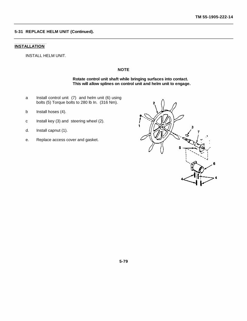
TM 55-1905-222-14
5-31 REPLACE HELM UNIT (Continued).
INSTALLATION
INSTALL HELM UNIT.
NOTE
Rotate control unit shaft while bringing surfaces into contact.This will allow splines on control unit and helm unit to engage.
a Install control unit (7) and helm unit (6) usingbolts (5) Torque bolts to 280 lb In. (316 Nm).
b Install hoses (4).
c Install key (3) and steering wheel (2).
d. Install capnut (1).
e. Replace access cover and gasket.
5-79
TM 55-1905-222-14
MAINTENANCE OF HYDRAULIC STEERING SYSTEM
5-32 REPLACE RELIEF VALVE (STEERING SYSTEM).
This task covers a. Disassembly b. Installation
INITIAL SETUP
Tools. Equipment Conditions:
Tool Kit, Mechanic's Rail Engine shut down.and Marine5180-00-629-9783 General Safety Instructions
Ensure that hydraulic pressurein the system is relieved beforeworking on system
REMOVAL
WARNINGThe oil pressure in the system must be released prior to servicingthe valve or other parts to prevent possible injury to personnel ordamage to equipment.
REMOVE RELIEF VALVE
a. Remove nipple (1) from relief valve (2).
b. Unscrew relief valve (2) from nipple (3).
5-80
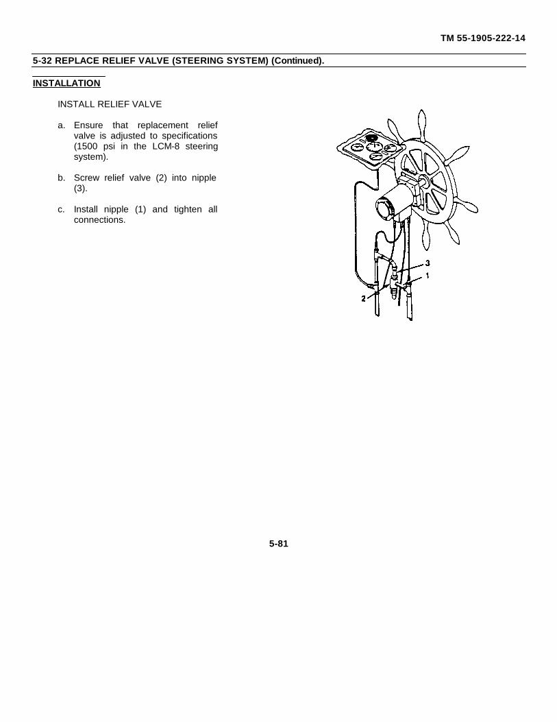
TM 55-1905-222-14
5-32 REPLACE RELIEF VALVE (STEERING SYSTEM) (Continued).
INSTALLATION
INSTALL RELIEF VALVE
a. Ensure that replacement reliefvalve is adjusted to specifications(1500 psi in the LCM-8 steeringsystem).
b. Screw relief valve (2) into nipple(3).
c. Install nipple (1) and tighten allconnections.
5-81
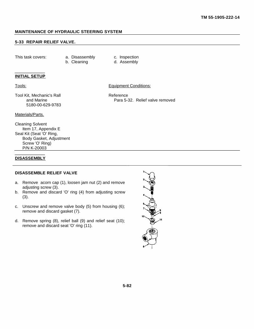
TM 55-1905-222-14
MAINTENANCE OF HYDRAULIC STEERING SYSTEM
5-33 REPAIR RELIEF VALVE.
This task covers: a. Disassembly c. Inspectionb. Cleaning d. Assembly
INITIAL SETUP
Tools: Equipment Conditions:
Tool Kit, Mechanic's Rall Referenceand Marine Para 5-32. Relief valve removed5180-00-629-9783
Materials/Parts.
Cleaning SolventItem 17, Appendix E
Seal Kit (Seat 'O' Ring,Body Gasket, AdjustmentScrew 'O' Ring)P/N K-20003
DISASSEMBLY
DISASSEMBLE RELIEF VALVE
a. Remove acorn cap (1), loosen jam nut (2) and removeadjusting screw (3).
b. Remove and discard 'O' ring (4) from adjusting screw(3).
c. Unscrew and remove valve body (5) from housing (6);remove and discard gasket (7).
d. Remove spring (8), relief ball (9) and relief seat (10);remove and discard seat 'O' ring (11).
5-82
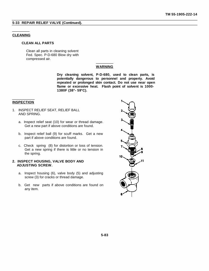
TM 55-1905-222-14
5-33 REPAIR RELIEF VALVE (Continued).
CLEANING
CLEAN ALL PARTS
Clean all parts in cleaning solventFed. Spec. P-D-680 Blow dry withcompressed air.
WARNING
Dry cleaning solvent, P-D-680, used to clean parts, ispotentially dangerous to personnel and property. Avoidrepeated or prolonged skin contact. Do not use near openflame or excessive heat. Flash point of solvent is 1000-1380F (38°- 59°C).
INSPECTION
1. INSPECT RELIEF SEAT, RELIEF BALLAND SPRING.
a. Inspect relief seat (10) for wear or thread damage.Get a new part if above conditions are found.
b. Inspect relief ball (9) for scuff marks. Get a newpart if above conditions are found.
c. Check spring (8) for distortion or loss of tension.Get a new spring if there is little or no tension inthe spring.
2. INSPECT HOUSING, VALVE BODY ANDADJUSTING SCREW.
a. Inspect housing (6), valve body (5) and adjustingscrew (3) for cracks or thread damage.
b. Get new parts if above conditions are found onany item.
5-83
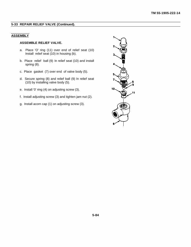
TM 55-1905-222-14
5-33 REPAIR RELIEF VALVE (Continued).
ASSEMBLY
ASSEMBLE RELIEF VALVE.
a. Place 'O' ring (11) over end of relief seat (10)Install relief seat (10) in housing (b).
b. Place relief ball (9) In relief seat (10) and installspring (8).
c. Place gasket (7) over end of valve body (5).
d. Secure spring (8) and relief ball (9) In relief seat(10) by installing valve body (5).
e. Install '0' ring (4) on adjusting screw (3).
f. Install adjusting screw (3) and tighten jam nut (2).
g. Install acorn cap (1) on adjusting screw (3).
5-84
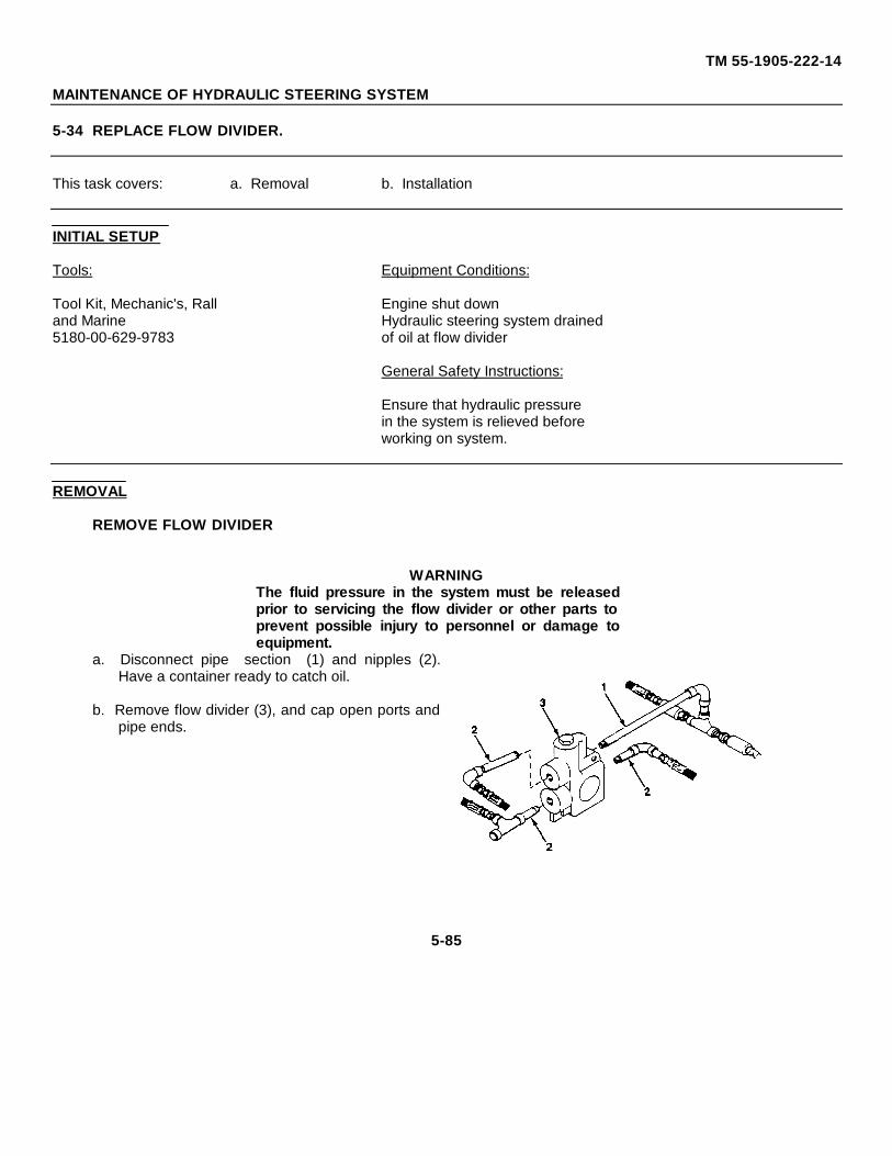
TM 55-1905-222-14
MAINTENANCE OF HYDRAULIC STEERING SYSTEM
5-34 REPLACE FLOW DIVIDER.
This task covers: a. Removal b. Installation
INITIAL SETUP
Tools: Equipment Conditions:
Tool Kit, Mechanic's, Rall Engine shut downand Marine Hydraulic steering system drained5180-00-629-9783 of oil at flow divider
General Safety Instructions:
Ensure that hydraulic pressurein the system is relieved beforeworking on system.
REMOVAL
REMOVE FLOW DIVIDER
WARNINGThe fluid pressure in the system must be releasedprior to servicing the flow divider or other parts toprevent possible injury to personnel or damage toequipment.
a. Disconnect pipe section (1) and nipples (2).Have a container ready to catch oil.
b. Remove flow divider (3), and cap open ports andpipe ends.
5-85
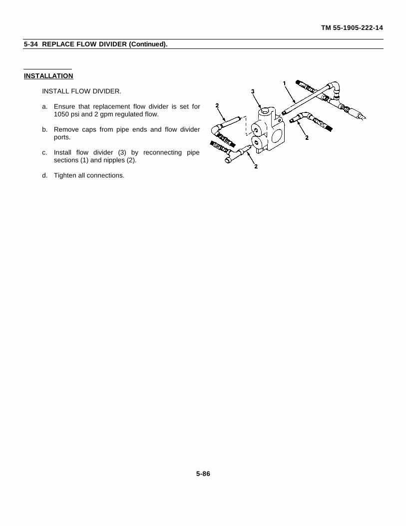
TM 55-1905-222-14
5-34 REPLACE FLOW DIVIDER (Continued).
INSTALLATION
INSTALL FLOW DIVIDER.
a. Ensure that replacement flow divider is set for1050 psi and 2 gpm regulated flow.
b. Remove caps from pipe ends and flow dividerports.
c. Install flow divider (3) by reconnecting pipesections (1) and nipples (2).
d. Tighten all connections.
5-86
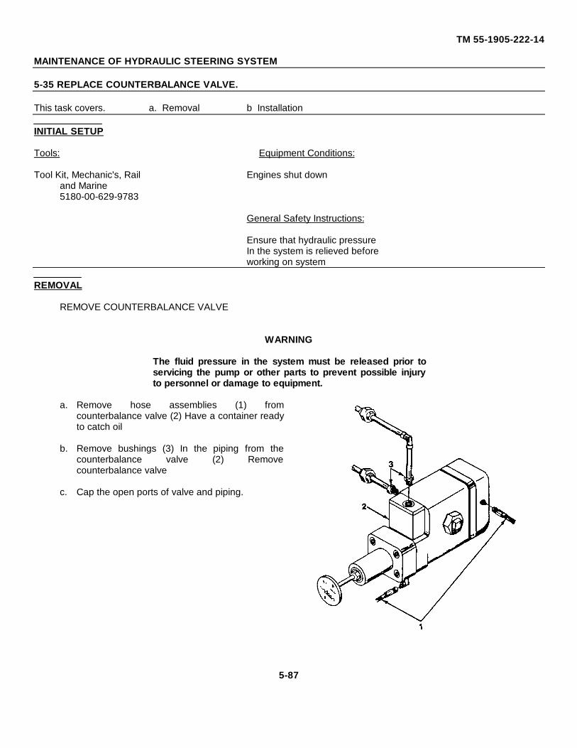
TM 55-1905-222-14
MAINTENANCE OF HYDRAULIC STEERING SYSTEM
5-35 REPLACE COUNTERBALANCE VALVE.
This task covers. a. Removal b Installation
INITIAL SETUP
Tools: Equipment Conditions:
Tool Kit, Mechanic's, Rail Engines shut downand Marine5180-00-629-9783
General Safety Instructions:
Ensure that hydraulic pressureIn the system is relieved beforeworking on system
REMOVAL
REMOVE COUNTERBALANCE VALVE
WARNING
The fluid pressure in the system must be released prior toservicing the pump or other parts to prevent possible injuryto personnel or damage to equipment.
a. Remove hose assemblies (1) fromcounterbalance valve (2) Have a container readyto catch oil
b. Remove bushings (3) In the piping from thecounterbalance valve (2) Removecounterbalance valve
c. Cap the open ports of valve and piping.
5-87
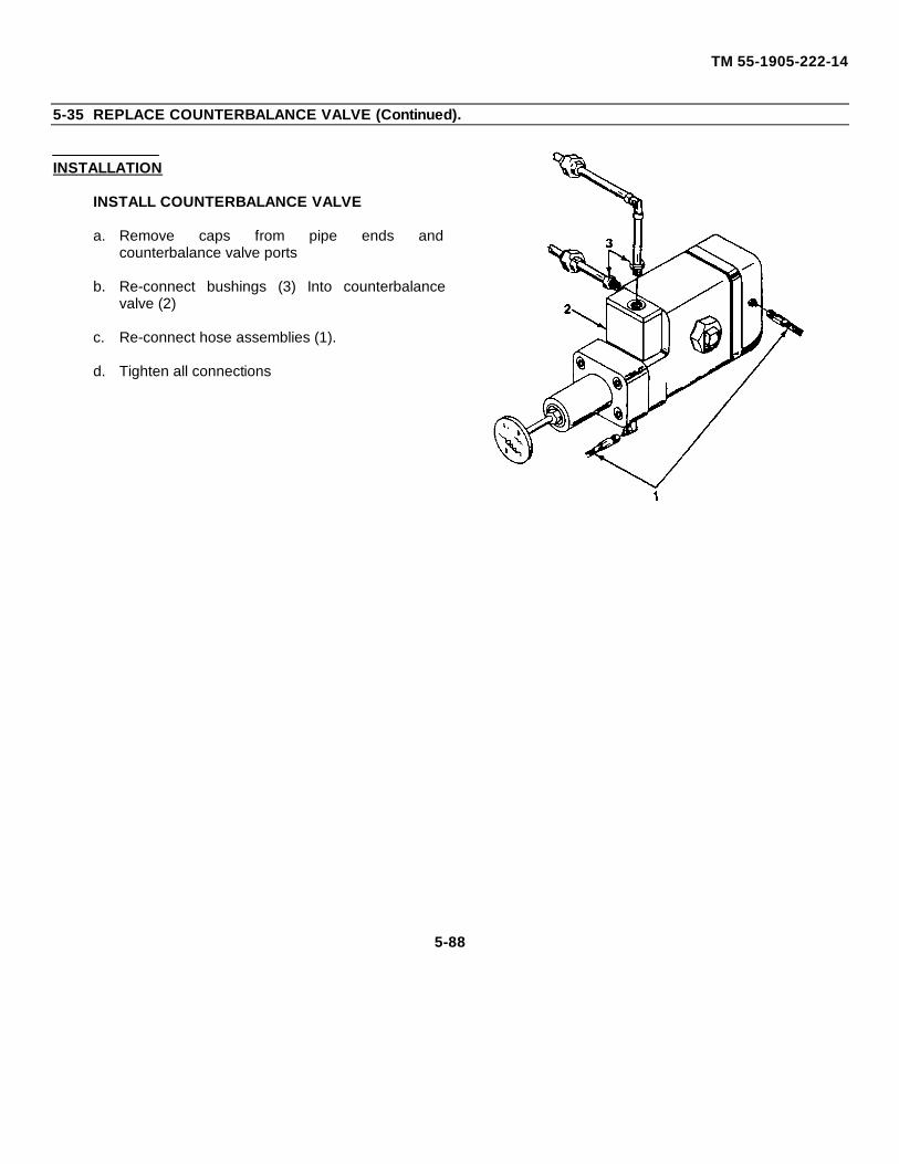
TM 55-1905-222-14
5-35 REPLACE COUNTERBALANCE VALVE (Continued).
INSTALLATION
INSTALL COUNTERBALANCE VALVE
a. Remove caps from pipe ends andcounterbalance valve ports
b. Re-connect bushings (3) Into counterbalancevalve (2)
c. Re-connect hose assemblies (1).
d. Tighten all connections
5-88
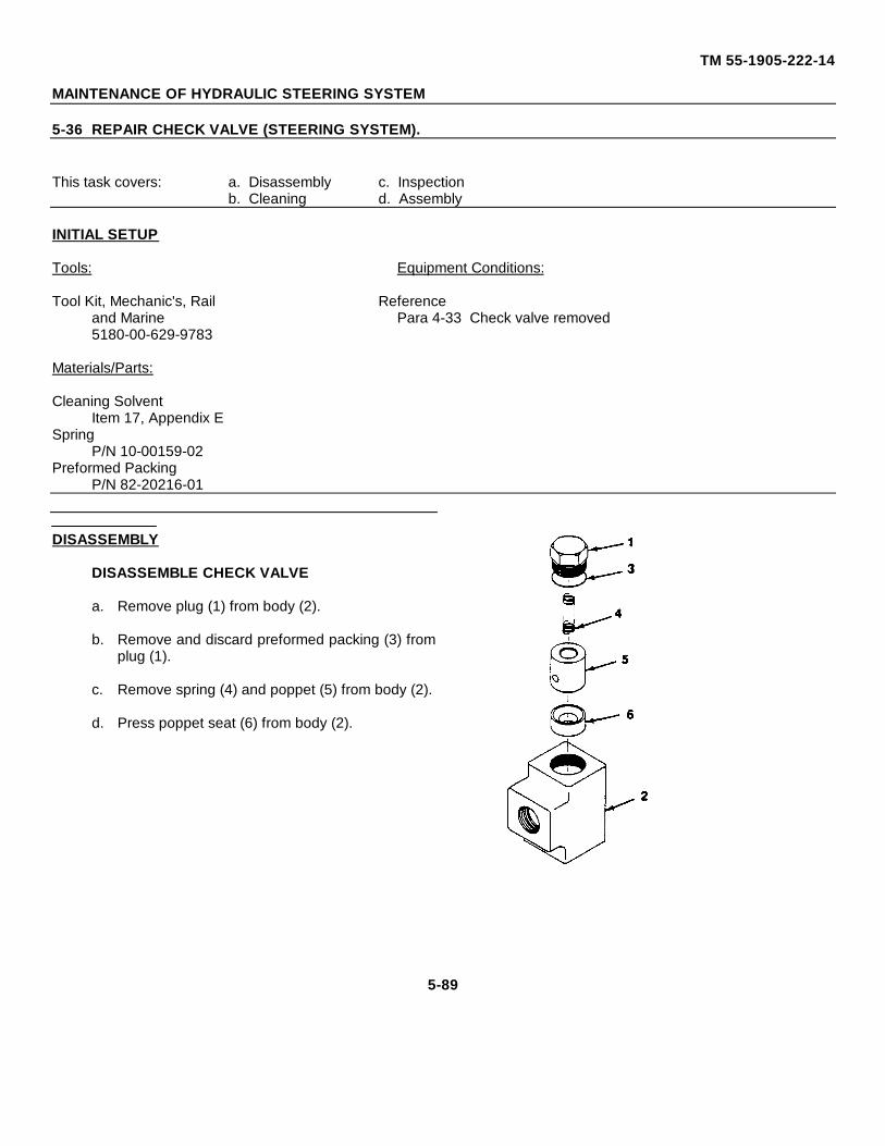
TM 55-1905-222-14
MAINTENANCE OF HYDRAULIC STEERING SYSTEM
5-36 REPAIR CHECK VALVE (STEERING SYSTEM).
This task covers: a. Disassembly c. Inspectionb. Cleaning d. Assembly
INITIAL SETUP
Tools: Equipment Conditions:
Tool Kit, Mechanic's, Rail Referenceand Marine Para 4-33 Check valve removed5180-00-629-9783
Materials/Parts:
Cleaning SolventItem 17, Appendix E
SpringP/N 10-00159-02
Preformed PackingP/N 82-20216-01
DISASSEMBLY
DISASSEMBLE CHECK VALVE
a. Remove plug (1) from body (2).
b. Remove and discard preformed packing (3) fromplug (1).
c. Remove spring (4) and poppet (5) from body (2).
d. Press poppet seat (6) from body (2).
5-89
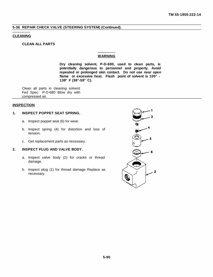
TM 55-1905-222-14
5-36 REPAIR CHECK VALVE (STEERING SYSTEM) (Continued).
CLEANING
CLEAN ALL PARTS
WARNING
Dry cleaning solvent, P-D-680, used to clean parts, ispotentially dangerous to personnel and property. Avoidrepeated or prolonged skin contact. Do not use near openflame or excessive heat. Flash point of solvent is 100°-138°F (38°-59°C).
Clean all parts in cleaning solventFed Spec P-D-680 Blow dry withcompressed air.
INSPECTION
1. INSPECT POPPET SEAT SPRING.
a. Inspect poppet seat (6) for wear.
b. Inspect spring (4) for distortion and loss oftension.
c. Get replacement parts as necessary.
2. INSPECT PLUG AND VALVE BODY.
a. Inspect valve body (2) for cracks or threaddamage.
b. Inspect plug (1) for thread damage Replace asnecessary.
5-90
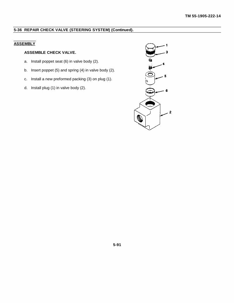
TM 55-1905-222-14
5-36 REPAIR CHECK VALVE (STEERING SYSTEM) (Continued).
ASSEMBLY
ASSEMBLE CHECK VALVE.
a. Install poppet seat (6) in valve body (2).
b. Insert poppet (5) and spring (4) in valve body (2).
c. Install a new preformed packing (3) on plug (1).
d. Install plug (1) in valve body (2).
5-91
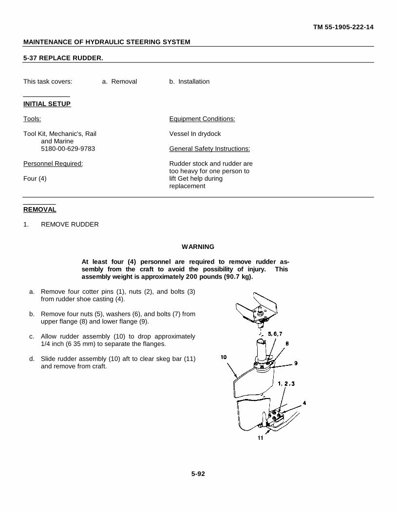
TM 55-1905-222-14
MAINTENANCE OF HYDRAULIC STEERING SYSTEM
5-37 REPLACE RUDDER.
This task covers: a. Removal b. Installation
INITIAL SETUP
Tools: Equipment Conditions:
Tool Kit, Mechanic's, Rail Vessel In drydockand Marine5180-00-629-9783 General Safety Instructions:
Personnel Required: Rudder stock and rudder aretoo heavy for one person to
Four (4) lift Get help duringreplacement
REMOVAL
1. REMOVE RUDDER
WARNING
At least four (4) personnel are required to remove rudder as-sembly from the craft to avoid the possibility of injury. Thisassembly weight is approximately 200 pounds (90.7 kg).
a. Remove four cotter pins (1), nuts (2), and bolts (3)from rudder shoe casting (4).
b. Remove four nuts (5), washers (6), and bolts (7) fromupper flange (8) and lower flange (9).
c. Allow rudder assembly (10) to drop approximately1/4 inch (6 35 mm) to separate the flanges.
d. Slide rudder assembly (10) aft to clear skeg bar (11)and remove from craft.
5-92
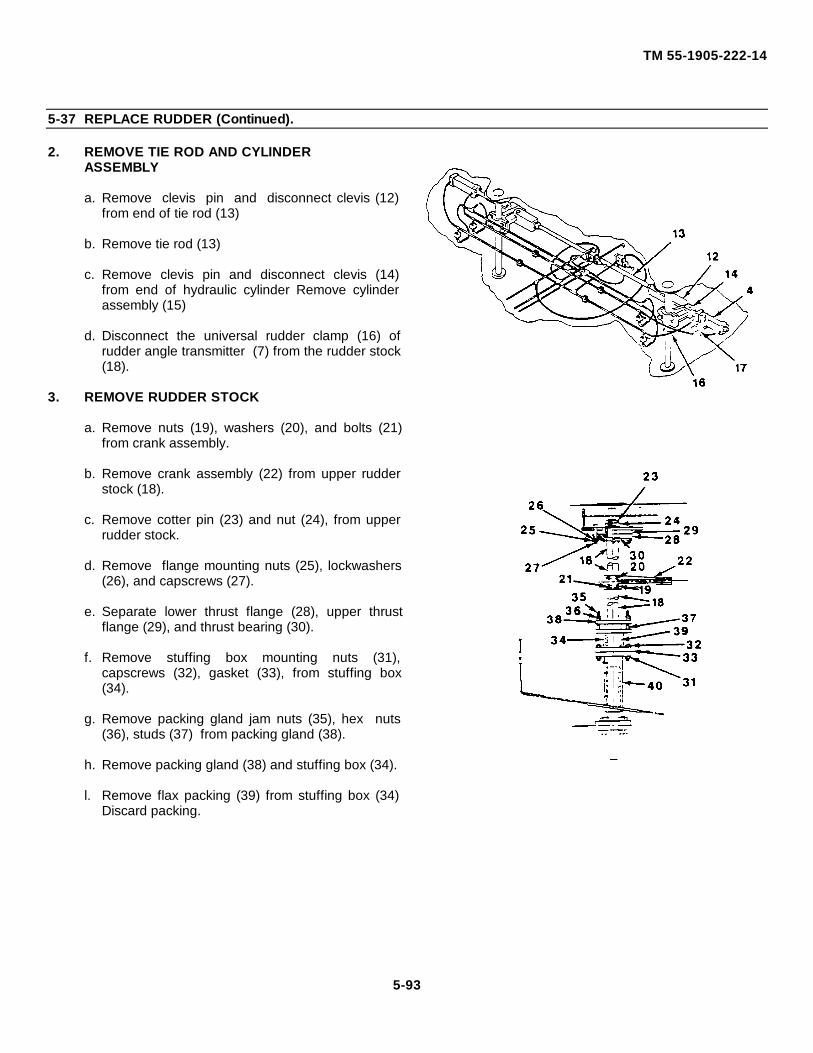
TM 55-1905-222-14
5-37 REPLACE RUDDER (Continued).
2. REMOVE TIE ROD AND CYLINDERASSEMBLY
a. Remove clevis pin and disconnect clevis (12)from end of tie rod (13)
b. Remove tie rod (13)
c. Remove clevis pin and disconnect clevis (14)from end of hydraulic cylinder Remove cylinderassembly (15)
d. Disconnect the universal rudder clamp (16) ofrudder angle transmitter (7) from the rudder stock(18).
3. REMOVE RUDDER STOCK
a. Remove nuts (19), washers (20), and bolts (21)from crank assembly.
b. Remove crank assembly (22) from upper rudderstock (18).
c. Remove cotter pin (23) and nut (24), from upperrudder stock.
d. Remove flange mounting nuts (25), lockwashers(26), and capscrews (27).
e. Separate lower thrust flange (28), upper thrustflange (29), and thrust bearing (30).
f. Remove stuffing box mounting nuts (31),capscrews (32), gasket (33), from stuffing box(34).
g. Remove packing gland jam nuts (35), hex nuts(36), studs (37) from packing gland (38).
h. Remove packing gland (38) and stuffing box (34).
l. Remove flax packing (39) from stuffing box (34)Discard packing.
5-93
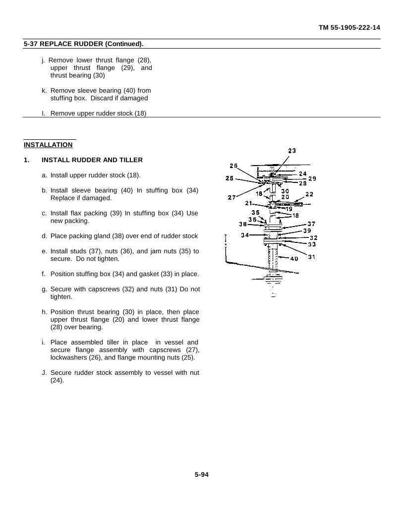
TM 55-1905-222-14
5-37 REPLACE RUDDER (Continued).
j. Remove lower thrust flange (28),upper thrust flange (29), andthrust bearing (30)
k. Remove sleeve bearing (40) fromstuffing box. Discard if damaged
I. Remove upper rudder stock (18)
INSTALLATION
1. INSTALL RUDDER AND TILLER
a. Install upper rudder stock (18).
b. Install sleeve bearing (40) In stuffing box (34)Replace if damaged.
c. Install flax packing (39) In stuffing box (34) Usenew packing.
d. Place packing gland (38) over end of rudder stock
e. Install studs (37), nuts (36), and jam nuts (35) tosecure. Do not tighten.
f. Position stuffing box (34) and gasket (33) in place.
g. Secure with capscrews (32) and nuts (31) Do nottighten.
h. Position thrust bearing (30) in place, then placeupper thrust flange (20) and lower thrust flange(28) over bearing.
i. Place assembled tiller in place in vessel andsecure flange assembly with capscrews (27),lockwashers (26), and flange mounting nuts (25).
J. Secure rudder stock assembly to vessel with nut(24).
5-94
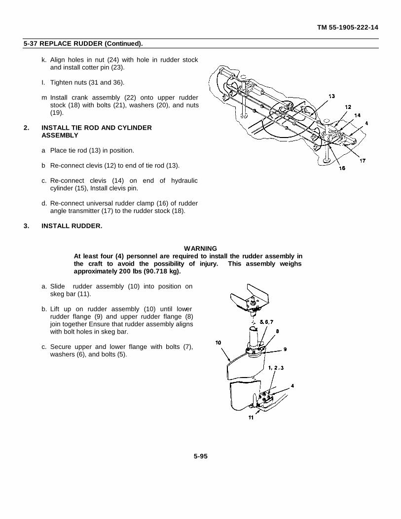
TM 55-1905-222-14
5-37 REPLACE RUDDER (Continued).
k. Align holes in nut (24) with hole in rudder stockand install cotter pin (23).
I. Tighten nuts (31 and 36).
m Install crank assembly (22) onto upper rudderstock (18) with bolts (21), washers (20), and nuts(19).
2. INSTALL TIE ROD AND CYLINDERASSEMBLY
a Place tie rod (13) in position.
b Re-connect clevis (12) to end of tie rod (13).
c. Re-connect clevis (14) on end of hydrauliccylinder (15), Install clevis pin.
d. Re-connect universal rudder clamp (16) of rudderangle transmitter (17) to the rudder stock (18).
3. INSTALL RUDDER.
WARNINGAt least four (4) personnel are required to install the rudder assembly inthe craft to avoid the possibility of injury. This assembly weighsapproximately 200 lbs (90.718 kg).
a. Slide rudder assembly (10) into position onskeg bar (11).
b. Lift up on rudder assembly (10) until lowerrudder flange (9) and upper rudder flange (8)join together Ensure that rudder assembly alignswith bolt holes in skeg bar.
c. Secure upper and lower flange with bolts (7),washers (6), and bolts (5).
5-95

TM 55-1905-222-14
5-37 REPLACE RUDDER (Continued).
d. Secure rudder shoe casting (4) to skegbar (11) with bolts (3), nuts (2) andcotter pin (1).
5-96
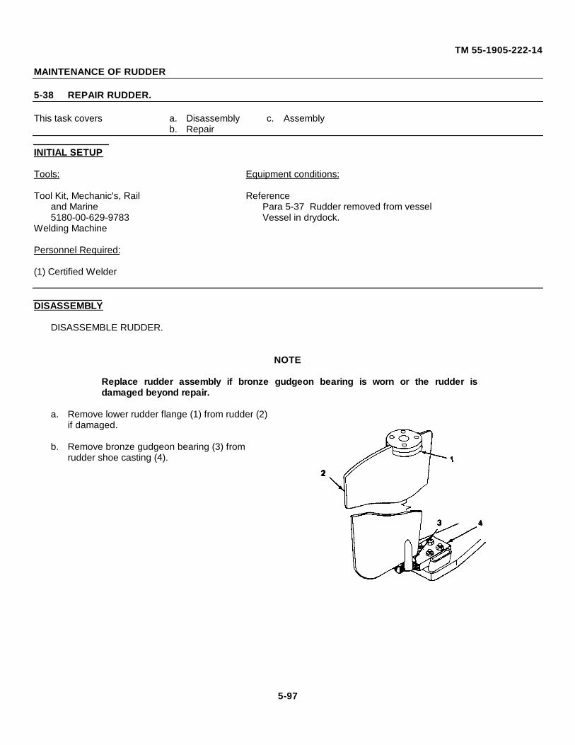
TM 55-1905-222-14
MAINTENANCE OF RUDDER
5-38 REPAIR RUDDER.
This task covers a. Disassembly c. Assemblyb. Repair
INITIAL SETUP
Tools: Equipment conditions:
Tool Kit, Mechanic's, Rail Referenceand Marine Para 5-37 Rudder removed from vessel5180-00-629-9783 Vessel in drydock.
Welding Machine
Personnel Required:
(1) Certified Welder
DISASSEMBLY
DISASSEMBLE RUDDER.
NOTE
Replace rudder assembly if bronze gudgeon bearing is worn or the rudder isdamaged beyond repair.
a. Remove lower rudder flange (1) from rudder (2) if damaged.
b. Remove bronze gudgeon bearing (3) from rudder shoe casting (4).
5-97
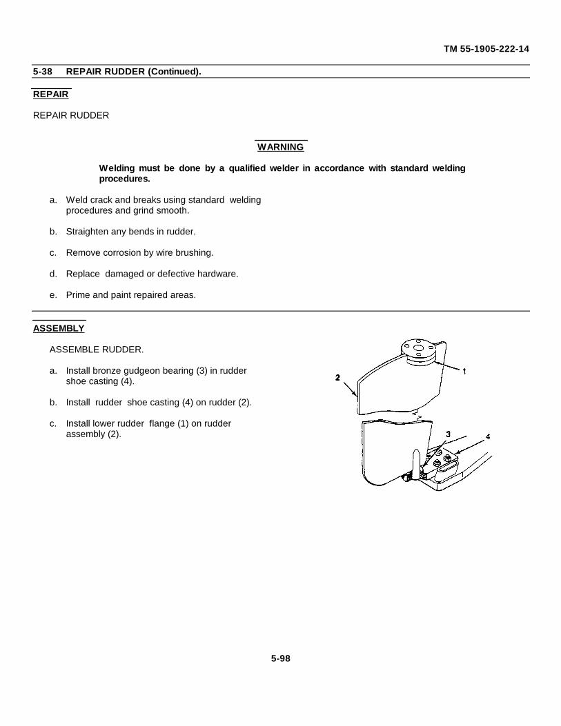
TM 55-1905-222-14
5-38 REPAIR RUDDER (Continued).
REPAIR
REPAIR RUDDER
WARNING
Welding must be done by a qualified welder in accordance with standard weldingprocedures.
a. Weld crack and breaks using standard weldingprocedures and grind smooth.
b. Straighten any bends in rudder.
c. Remove corrosion by wire brushing.
d. Replace damaged or defective hardware.
e. Prime and paint repaired areas.
ASSEMBLY
ASSEMBLE RUDDER.
a. Install bronze gudgeon bearing (3) in rudder shoe casting (4).
b. Install rudder shoe casting (4) on rudder (2).
c. Install lower rudder flange (1) on rudder assembly (2).
5-98
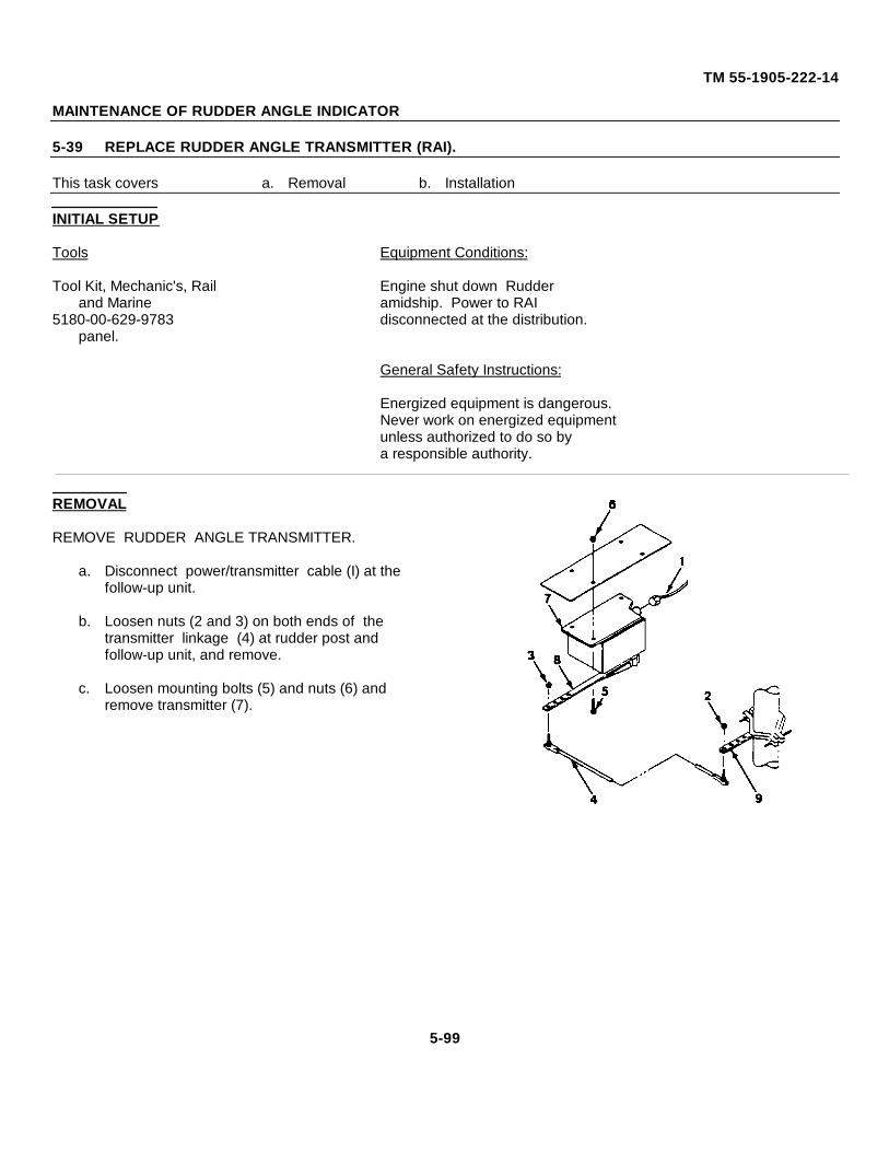
TM 55-1905-222-14
MAINTENANCE OF RUDDER ANGLE INDICATOR
5-39 REPLACE RUDDER ANGLE TRANSMITTER (RAI).
This task covers a. Removal b. Installation
INITIAL SETUP
Tools Equipment Conditions:
Tool Kit, Mechanic's, Rail Engine shut down Rudderand Marine amidship. Power to RAI
5180-00-629-9783 disconnected at the distribution.panel.
General Safety Instructions:
Energized equipment is dangerous.Never work on energized equipmentunless authorized to do so bya responsible authority.
REMOVAL
REMOVE RUDDER ANGLE TRANSMITTER.
a. Disconnect power/transmitter cable (I) at the follow-up unit.
b. Loosen nuts (2 and 3) on both ends of the transmitter linkage (4) at rudder post and follow-up unit, and remove.
c. Loosen mounting bolts (5) and nuts (6) and remove transmitter (7).
5-99
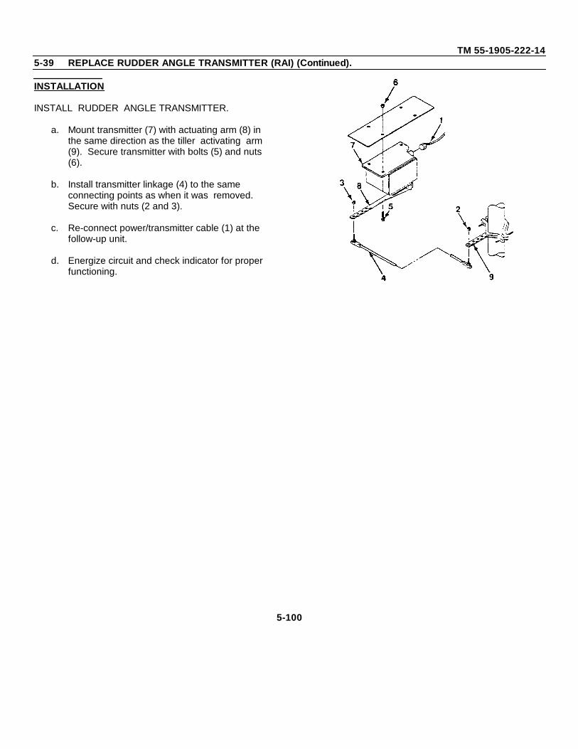
TM 55-1905-222-145-39 REPLACE RUDDER ANGLE TRANSMITTER (RAI) (Continued).
INSTALLATION
INSTALL RUDDER ANGLE TRANSMITTER.
a. Mount transmitter (7) with actuating arm (8) in the same direction as the tiller activating arm (9). Secure transmitter with bolts (5) and nuts (6).
b. Install transmitter linkage (4) to the same connecting points as when it was removed. Secure with nuts (2 and 3).
c. Re-connect power/transmitter cable (1) at the follow-up unit.
d. Energize circuit and check indicator for proper functioning.
5-100
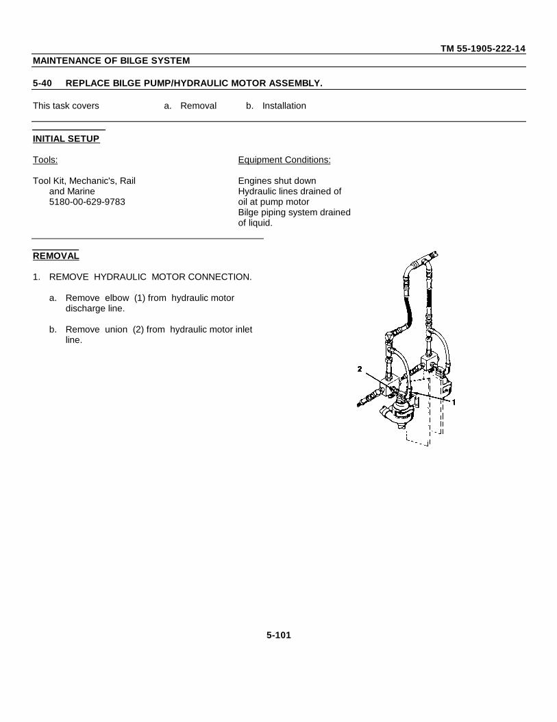
TM 55-1905-222-14MAINTENANCE OF BILGE SYSTEM
5-40 REPLACE BILGE PUMP/HYDRAULIC MOTOR ASSEMBLY.
This task covers a. Removal b. Installation
INITIAL SETUP
Tools: Equipment Conditions:
Tool Kit, Mechanic's, Rail Engines shut downand Marine Hydraulic lines drained of5180-00-629-9783 oil at pump motor
Bilge piping system drainedof liquid.
REMOVAL
1. REMOVE HYDRAULIC MOTOR CONNECTION.
a. Remove elbow (1) from hydraulic motor discharge line.
b. Remove union (2) from hydraulic motor inlet line.
5-101
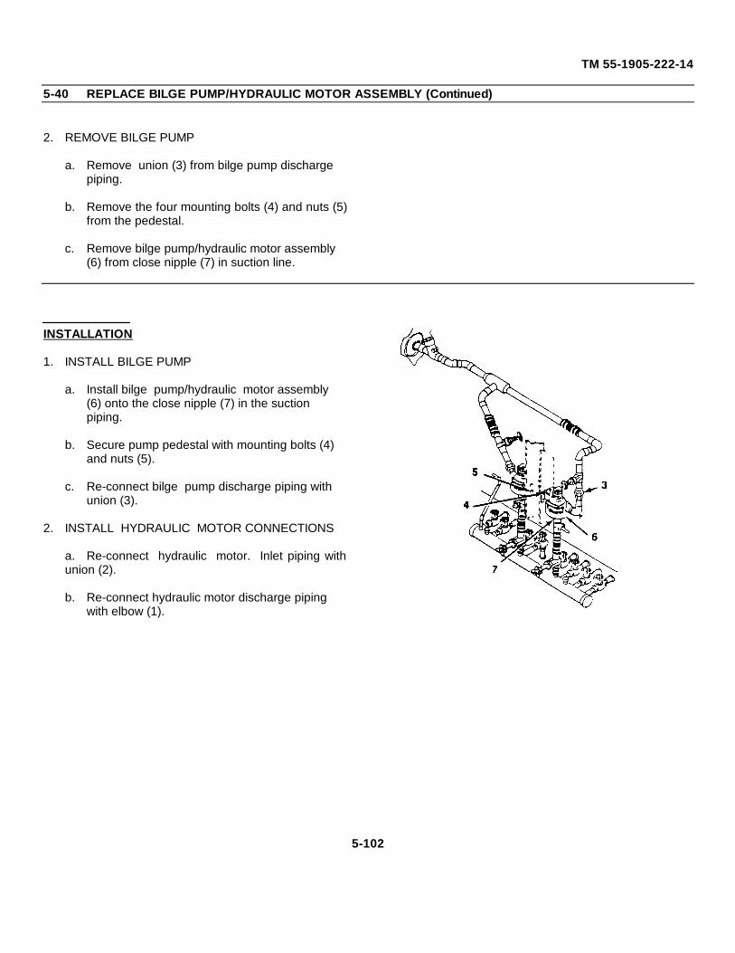
TM 55-1905-222-14
5-40 REPLACE BILGE PUMP/HYDRAULIC MOTOR ASSEMBLY (Continued)
2. REMOVE BILGE PUMP
a. Remove union (3) from bilge pump discharge piping.
b. Remove the four mounting bolts (4) and nuts (5)from the pedestal.
c. Remove bilge pump/hydraulic motor assembly (6) from close nipple (7) in suction line.
INSTALLATION
1. INSTALL BILGE PUMP
a. Install bilge pump/hydraulic motor assembly (6) onto the close nipple (7) in the suction piping.
b. Secure pump pedestal with mounting bolts (4) and nuts (5).
c. Re-connect bilge pump discharge piping with union (3).
2. INSTALL HYDRAULIC MOTOR CONNECTIONS
a. Re-connect hydraulic motor. Inlet piping withunion (2).
b. Re-connect hydraulic motor discharge piping with elbow (1).
5-102
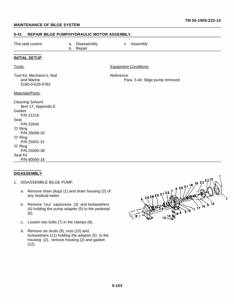
TM 55-1905-222-14MAINTENANCE OF BILGE SYSTEM
5-41 REPAIR BILGE PUMP/HYDRAULIC MOTOR ASSEMBLY.
This task covers- a. Disassembly c. Assemblyb. Repair
INITIAL SETUP
Tools: Equipment Conditions:
Tool Kit, Mechanic's, Rail Referenceand Marine Para. 5-40 Bilge pump removed5180-0-629-9783
Materials/Parts:
Cleaning SolventItem 17, Appendix E
GasketP/N 21216
SealP/N 22640
'O' RingP/N 25009-20
'O' RingP/N 25001-31
'O' RingP/N 25000-38
Seal KitP/N 80005-16
DISASSEMBLY
1. DISASSEMBLE BILGE PUMP.
a. Remove drain plugs (1) and drain housing (2) ofany residual water.
b. Remove four capscrews (3) and lockwashers (4) holding the pump adapter (5) to the pedestal (6).
c. Loosen two bolts (7) in the clamps (8).
d. Remove six studs (9), nuts (10) and lockwashers (11) holding the adapter (5) to the housing (2), remove housing (2) and gasket (12).
5-103
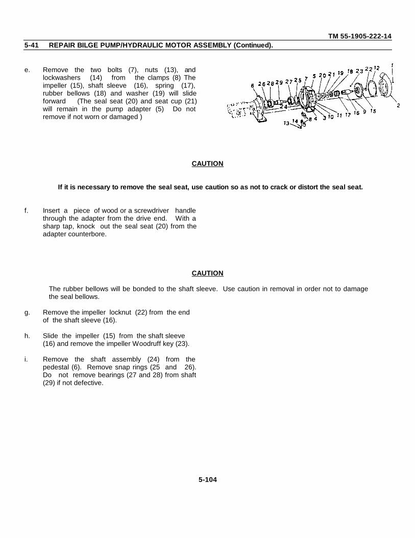
TM 55-1905-222-145-41 REPAIR BILGE PUMP/HYDRAULIC MOTOR ASSEMBLY (Continued).
e. Remove the two bolts (7), nuts (13), andlockwashers (14) from the clamps (8) Theimpeller (15), shaft sleeve (16), spring (17),rubber bellows (18) and washer (19) will slideforward (The seal seat (20) and seat cup (21)will remain in the pump adapter (5) Do notremove if not worn or damaged )
CAUTION
If it is necessary to remove the seal seat, use caution so as not to crack or distort the seal seat.
f. Insert a piece of wood or a screwdriver handlethrough the adapter from the drive end. With asharp tap, knock out the seal seat (20) from theadapter counterbore.
CAUTION
The rubber bellows will be bonded to the shaft sleeve. Use caution in removal in order not to damagethe seal bellows.
g. Remove the impeller locknut (22) from the end of the shaft sleeve (16).
h. Slide the impeller (15) from the shaft sleeve (16) and remove the impeller Woodruff key (23).
i. Remove the shaft assembly (24) from thepedestal (6). Remove snap rings (25 and 26).Do not remove bearings (27 and 28) from shaft(29) if not defective.
5-104
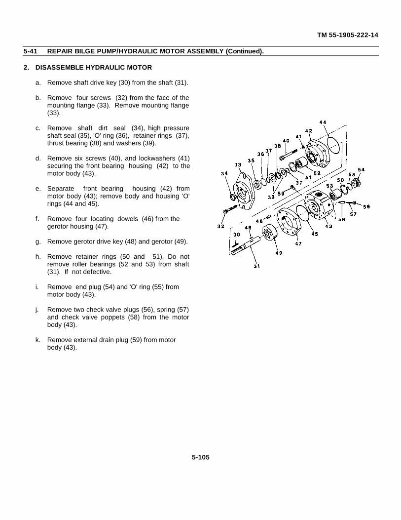
TM 55-1905-222-14
5-41 REPAIR BILGE PUMP/HYDRAULIC MOTOR ASSEMBLY (Continued).
2. DISASSEMBLE HYDRAULIC MOTOR
a. Remove shaft drive key (30) from the shaft (31).
b. Remove four screws (32) from the face of themounting flange (33). Remove mounting flange(33).
c. Remove shaft dirt seal (34), high pressureshaft seal (35), 'O' ring (36), retainer rings (37),thrust bearing (38) and washers (39).
d. Remove six screws (40), and lockwashers (41)securing the front bearing housing (42) to themotor body (43).
e. Separate front bearing housing (42) frommotor body (43); remove body and housing 'O'rings (44 and 45).
f. Remove four locating dowels (46) from the gerotor housing (47).
g. Remove gerotor drive key (48) and gerotor (49).
h. Remove retainer rings (50 and 51). Do notremove roller bearings (52 and 53) from shaft(31). If not defective.
i. Remove end plug (54) and 'O' ring (55) from motor body (43).
j. Remove two check valve plugs (56), spring (57)and check valve poppets (58) from the motorbody (43).
k. Remove external drain plug (59) from motor body (43).
5-105
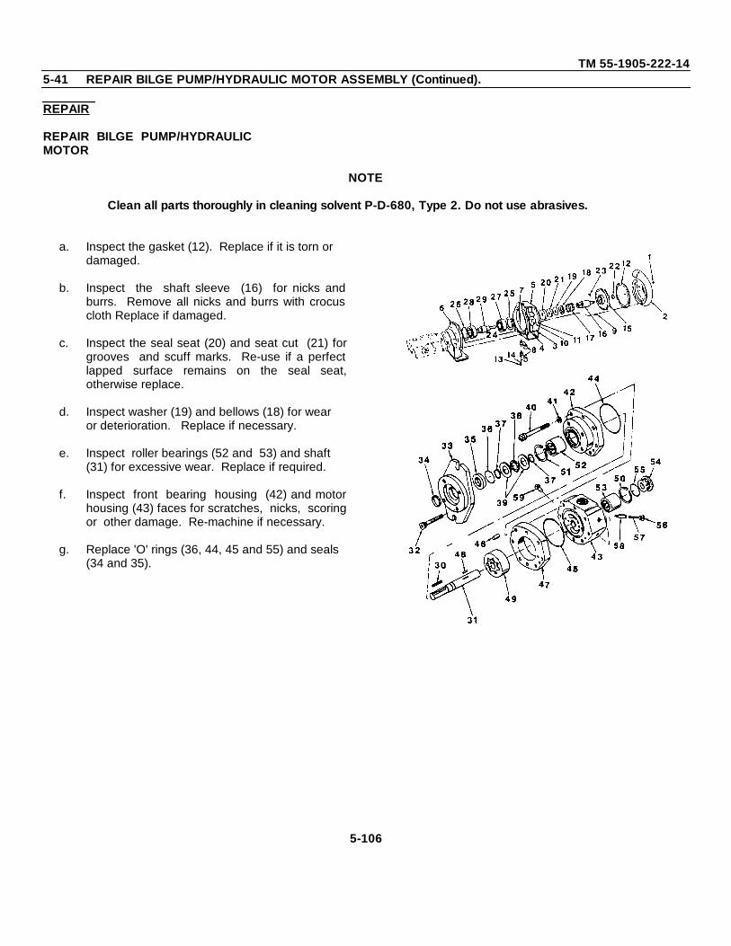
TM 55-1905-222-145-41 REPAIR BILGE PUMP/HYDRAULIC MOTOR ASSEMBLY (Continued).
REPAIR
REPAIR BILGE PUMP/HYDRAULICMOTOR
NOTE
Clean all parts thoroughly in cleaning solvent P-D-680, Type 2. Do not use abrasives.
a. Inspect the gasket (12). Replace if it is torn or damaged.
b. Inspect the shaft sleeve (16) for nicks andburrs. Remove all nicks and burrs with crocuscloth Replace if damaged.
c. Inspect the seal seat (20) and seat cut (21) forgrooves and scuff marks. Re-use if a perfectlapped surface remains on the seal seat,otherwise replace.
d. Inspect washer (19) and bellows (18) for wear or deterioration. Replace if necessary.
e. Inspect roller bearings (52 and 53) and shaft (31) for excessive wear. Replace if required.
f. Inspect front bearing housing (42) and motorhousing (43) faces for scratches, nicks, scoringor other damage. Re-machine if necessary.
g. Replace 'O' rings (36, 44, 45 and 55) and seals (34 and 35).
5-106
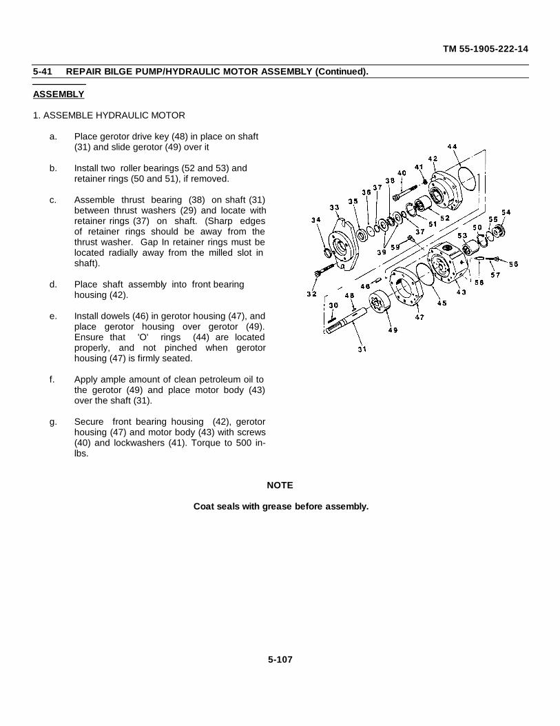
TM 55-1905-222-14
5-41 REPAIR BILGE PUMP/HYDRAULIC MOTOR ASSEMBLY (Continued).
ASSEMBLY
1. ASSEMBLE HYDRAULIC MOTOR
a. Place gerotor drive key (48) in place on shaft (31) and slide gerotor (49) over it
b. Install two roller bearings (52 and 53) and retainer rings (50 and 51), if removed.
c. Assemble thrust bearing (38) on shaft (31)between thrust washers (29) and locate withretainer rings (37) on shaft. (Sharp edgesof retainer rings should be away from thethrust washer. Gap In retainer rings must belocated radially away from the milled slot inshaft).
d. Place shaft assembly into front bearing housing (42).
e. Install dowels (46) in gerotor housing (47), andplace gerotor housing over gerotor (49).Ensure that 'O' rings (44) are locatedproperly, and not pinched when gerotorhousing (47) is firmly seated.
f. Apply ample amount of clean petroleum oil tothe gerotor (49) and place motor body (43)over the shaft (31).
g. Secure front bearing housing (42), gerotorhousing (47) and motor body (43) with screws(40) and lockwashers (41). Torque to 500 in-lbs.
NOTE
Coat seals with grease before assembly.
5-107
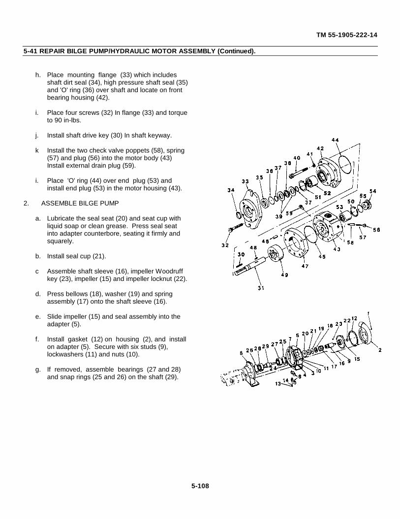
TM 55-1905-222-14
5-41 REPAIR BILGE PUMP/HYDRAULIC MOTOR ASSEMBLY (Continued).
h. Place mounting flange (33) which includes shaft dirt seal (34), high pressure shaft seal (35) and 'O' ring (36) over shaft and locate on front bearing housing (42).
i. Place four screws (32) In flange (33) and torque to 90 in-lbs.
j. Install shaft drive key (30) In shaft keyway.
k Install the two check valve poppets (58), spring (57) and plug (56) into the motor body (43) Install external drain plug (59).
i. Place 'O' ring (44) over end plug (53) and install end plug (53) in the motor housing (43).
2. ASSEMBLE BILGE PUMP
a. Lubricate the seal seat (20) and seat cup with liquid soap or clean grease. Press seal seat into adapter counterbore, seating it firmly and squarely.
b. Install seal cup (21).
c Assemble shaft sleeve (16), impeller Woodruff key (23), impeller (15) and impeller locknut (22).
d. Press bellows (18), washer (19) and spring assembly (17) onto the shaft sleeve (16).
e. Slide impeller (15) and seal assembly into the adapter (5).
f. Install gasket (12) on housing (2), and install on adapter (5). Secure with six studs (9), lockwashers (11) and nuts (10).
g. If removed, assemble bearings (27 and 28) and snap rings (25 and 26) on the shaft (29).
5-108
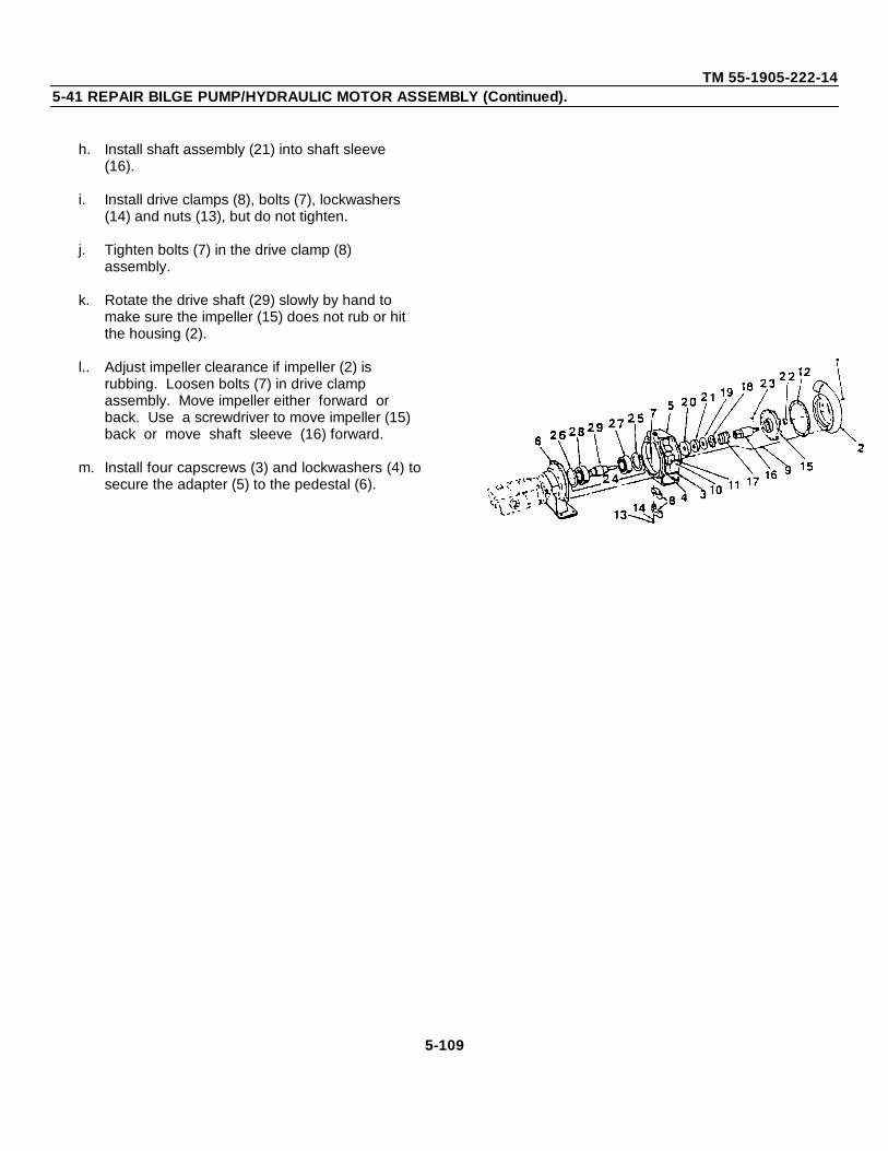
TM 55-1905-222-145-41 REPAIR BILGE PUMP/HYDRAULIC MOTOR ASSEMBLY (Continued).
h. Install shaft assembly (21) into shaft sleeve (16).
i. Install drive clamps (8), bolts (7), lockwashers (14) and nuts (13), but do not tighten.
j. Tighten bolts (7) in the drive clamp (8) assembly.
k. Rotate the drive shaft (29) slowly by hand to make sure the impeller (15) does not rub or hit the housing (2).
l.. Adjust impeller clearance if impeller (2) is rubbing. Loosen bolts (7) in drive clamp assembly. Move impeller either forward or back. Use a screwdriver to move impeller (15) back or move shaft sleeve (16) forward.
m. Install four capscrews (3) and lockwashers (4) tosecure the adapter (5) to the pedestal (6).
5-109
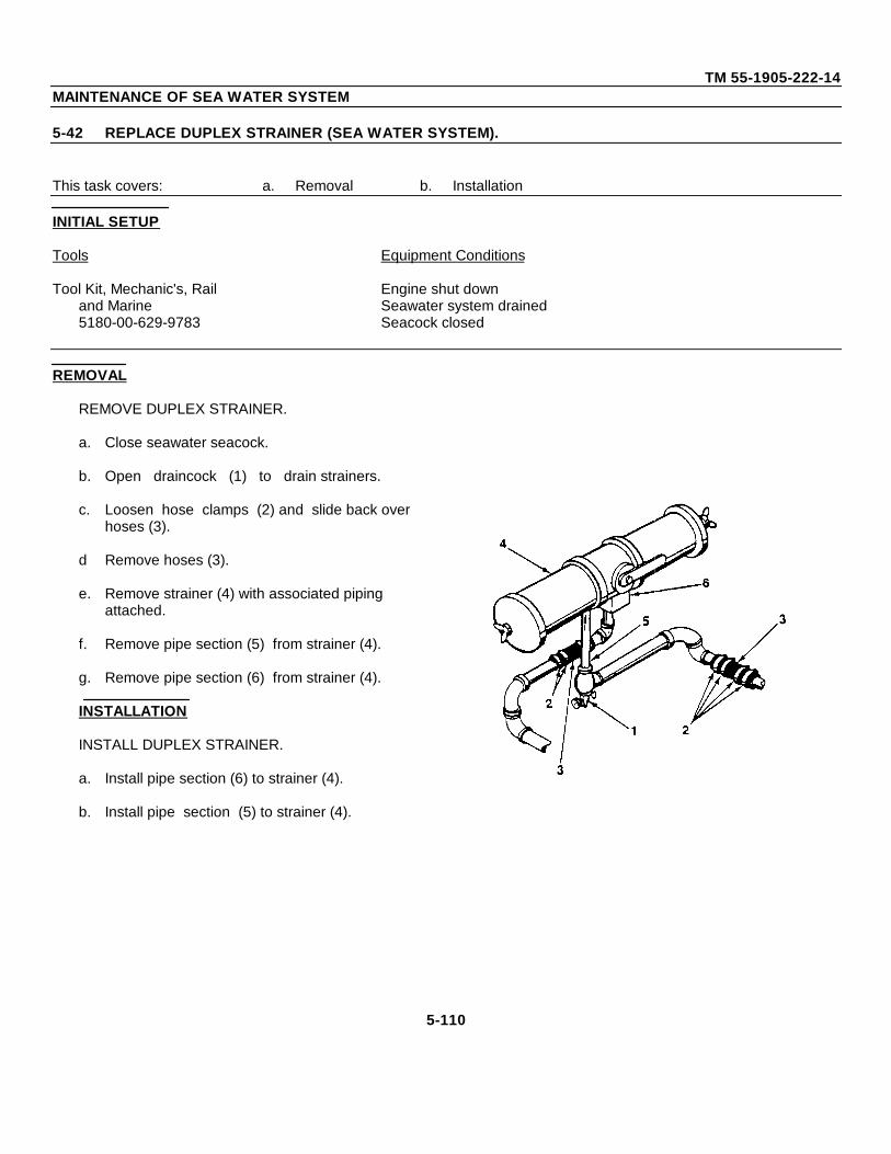
TM 55-1905-222-14MAINTENANCE OF SEA WATER SYSTEM
5-42 REPLACE DUPLEX STRAINER (SEA WATER SYSTEM).
This task covers: a. Removal b. Installation
INITIAL SETUP
Tools Equipment Conditions
Tool Kit, Mechanic's, Rail Engine shut downand Marine Seawater system drained5180-00-629-9783 Seacock closed
REMOVAL
REMOVE DUPLEX STRAINER.
a. Close seawater seacock.
b. Open draincock (1) to drain strainers.
c. Loosen hose clamps (2) and slide back over hoses (3).
d Remove hoses (3).
e. Remove strainer (4) with associated piping attached.
f. Remove pipe section (5) from strainer (4).
g. Remove pipe section (6) from strainer (4).
INSTALLATION
INSTALL DUPLEX STRAINER.
a. Install pipe section (6) to strainer (4).
b. Install pipe section (5) to strainer (4).
5-110
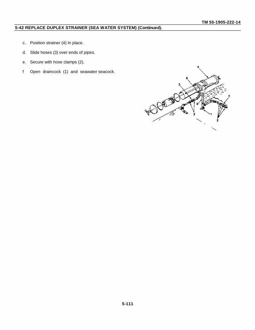
TM 55-1905-222-145-42 REPLACE DUPLEX STRAINER (SEA WATER SYSTEM) (Continued).
c. Position strainer (4) In place.
d. Slide hoses (3) over ends of pipes.
e. Secure with hose clamps (2).
f Open draincock (1) and seawater seacock.
5-111
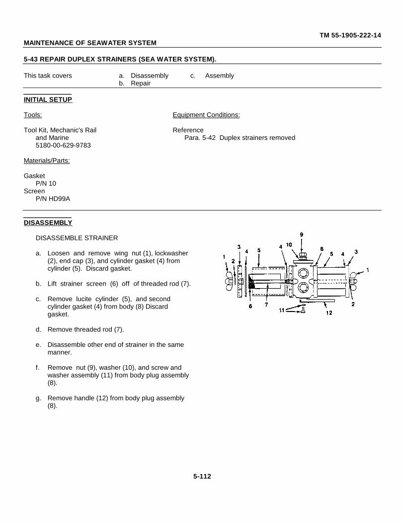
TM 55-1905-222-14MAINTENANCE OF SEAWATER SYSTEM
5-43 REPAIR DUPLEX STRAINERS (SEA WATER SYSTEM).
This task covers a. Disassembly c. Assemblyb. Repair
INITIAL SETUP
Tools: Equipment Conditions:
Tool Kit, Mechanic's Rail Referenceand Marine Para. 5-42 Duplex strainers removed5180-00-629-9783
Materials/Parts:
GasketP/N 10
ScreenP/N HD99A
DISASSEMBLY
DISASSEMBLE STRAINER
a. Loosen and remove wing nut (1), lockwasher (2), end cap (3), and cylinder gasket (4) from cylinder (5). Discard gasket.
b. Lift strainer screen (6) off of threaded rod (7).
c. Remove lucite cylinder (5), and second cylinder gasket (4) from body (8) Discard gasket.
d. Remove threaded rod (7).
e. Disassemble other end of strainer in the same manner.
f. Remove nut (9), washer (10), and screw and washer assembly (11) from body plug assembly (8).
g. Remove handle (12) from body plug assembly (8).
5-112

TM 55-1905-222-145-43 REPAIR DUPLEX STRAINERS (SEA WATER SYSTEM) (Continued).
REPAIR
REPAIR STRAINER
a. Replace gaskets (4) Replacescreens (6) as necessary.
b. Straighten distorted threaded rods.
ASSEMBLY
ASSEMBLE STRAINER
a Install threaded rod (7), if removed.
b Position gasket (4) in place on body (8) and insert strainer (6) over rod (7). Use new gasket.
c Place lucite cylinder (5) on body (8).
d. Place gasket (4) over end of cylinder. Use new gasket.
e. Install end cap (3) onto cylinder (5) with washer (2), and wing nut (1).
f. Assemble other end of strainer in the same manner.
5-113
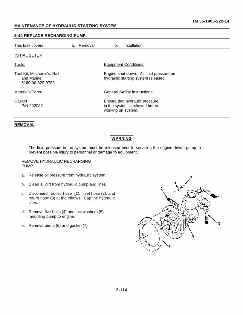
TM 55-1905-222-14MAINTENANCE OF HYDRAULIC STARTING SYSTEM
5-44 REPLACE RECHARGING PUMP.
This task covers a. Removal b. Installation
INITIAL SETUP
Tools: Equipment Conditions:
Tool Kit, Mechanic's, Rail Engine shut down. All fluid pressure onand Marine hydraulic starting system released.5180-00-629-9783
Materials/Parts: General Safety Instructions:
Gasket Ensure that hydraulic pressureP/N 202082 in the system is relieved before
working on system.
REMOVAL
WARNING
The fluid pressure in the system must be released prior to servicing the engine-driven pump toprevent possible injury to personnel or damage to equipment.
REMOVE HYDRAULIC RECHARGINGPUMP
a. Release oil pressure from hydraulic system.
b. Clean all dirt from hydraulic pump and lines.
c. Disconnect outlet hose (1), inlet hose (2), andreturn hose (3) at the elbows. Cap the hydrauliclines.
d. Remove five bolts (4) and lockwashers (5) mounting pump to engine.
e. Remove pump (6) and gasket (7).
5-114
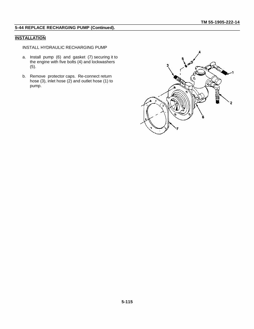
TM 55-1905-222-145-44 REPLACE RECHARGING PUMP (Continued).
INSTALLATION
INSTALL HYDRAULIC RECHARGING PUMP
a. Install pump (6) and gasket (7) securing it to the engine with five bolts (4) and lockwashers (5).
b. Remove protector caps. Re-connect return hose (3), inlet hose (2) and outlet hose (1) to pump.
5-115
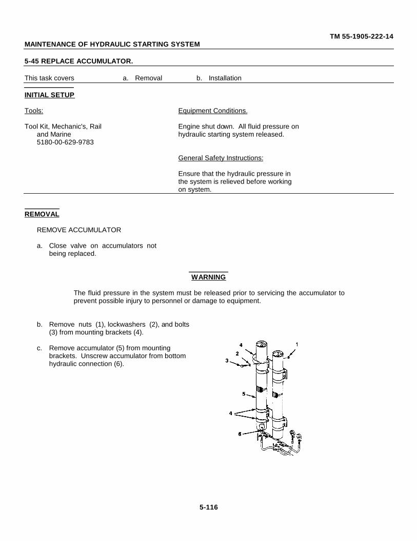
TM 55-1905-222-14MAINTENANCE OF HYDRAULIC STARTING SYSTEM
5-45 REPLACE ACCUMULATOR.
This task covers a. Removal b. Installation
INITIAL SETUP
Tools: Equipment Conditions.
Tool Kit, Mechanic's, Rail Engine shut down. All fluid pressure onand Marine hydraulic starting system released.5180-00-629-9783
General Safety Instructions:
Ensure that the hydraulic pressure inthe system is relieved before workingon system.
REMOVAL
REMOVE ACCUMULATOR
a. Close valve on accumulators notbeing replaced.
WARNING
The fluid pressure in the system must be released prior to servicing the accumulator toprevent possible injury to personnel or damage to equipment.
b. Remove nuts (1), lockwashers (2), and bolts (3) from mounting brackets (4).
c. Remove accumulator (5) from mounting brackets. Unscrew accumulator from bottom hydraulic connection (6).
5-116
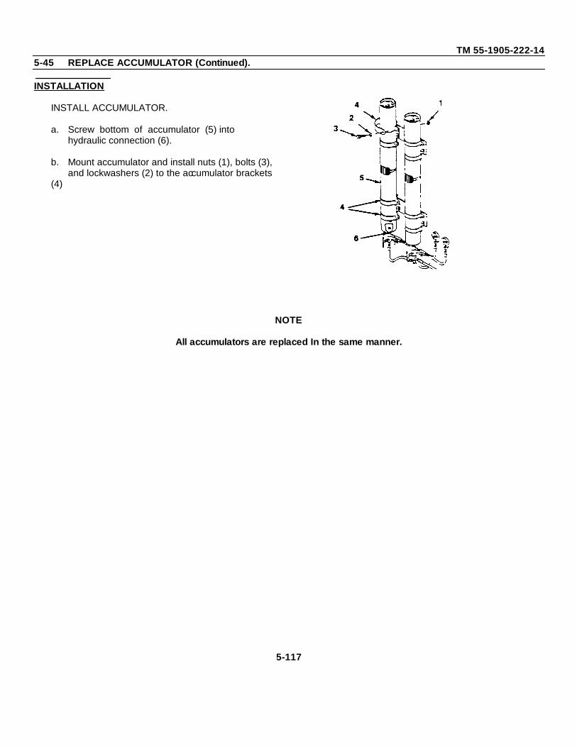
TM 55-1905-222-145-45 REPLACE ACCUMULATOR (Continued).
INSTALLATION
INSTALL ACCUMULATOR.
a. Screw bottom of accumulator (5) into hydraulic connection (6).
b. Mount accumulator and install nuts (1), bolts (3),and lockwashers (2) to the accumulator brackets
(4)
NOTE
All accumulators are replaced In the same manner.
5-117
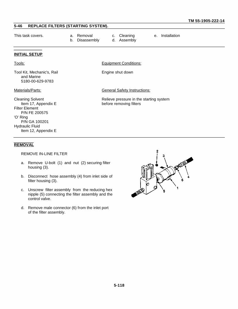
TM 55-1905-222-145-46 REPLACE FILTERS (STARTING SYSTEM).
This task covers. a. Removal c. Cleaning e. Installationb. Disassembly d. Assembly
INITIAL SETUP
Tools: Equipment Conditions:
Tool Kit, Mechanic's, Rail Engine shut downand Marine5180-00-629-9783
Materials/Parts: General Safety Instructions:
Cleaning Solvent Relieve pressure in the starting systemItem 17, Appendix E before removing filters
Filter ElementP/N FE 200575
'O' RingP/N GA 100201
Hydraulic FluidItem 12, Appendix E
REMOVAL
REMOVE IN-LINE FILTER
a. Remove U-bolt (1) and nut (2) securing filter housing (3).
b. Disconnect hose assembly (4) from inlet side offilter housing (3).
c. Unscrew filter assembly from the reducing hexnipple (5) connecting the filter assembly and thecontrol valve.
d. Remove male connector (6) from the inlet port of the filter assembly.
5-118
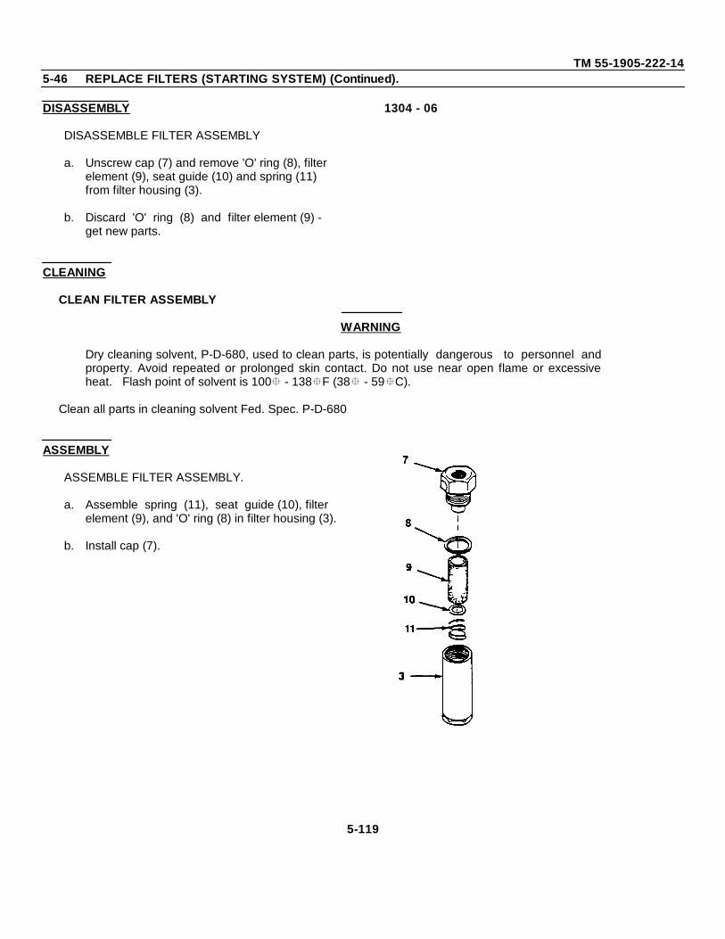
TM 55-1905-222-145-46 REPLACE FILTERS (STARTING SYSTEM) (Continued).
DISASSEMBLY
DISASSEMBLE FILTER ASSEMBLY
a. Unscrew cap (7) and remove 'O' ring (8), filter element (9), seat guide (10) and spring (11) from filter housing (3).
b. Discard 'O' ring (8) and filter element (9) - get new parts.
1304 - 06
CLEANING
CLEAN FILTER ASSEMBLY
WARNING
Dry cleaning solvent, P-D-680, used to clean parts, is potentially dangerous to personnel andproperty. Avoid repeated or prolonged skin contact. Do not use near open flame or excessiveheat. Flash point of solvent is 100 - 138F (38 - 59C).
Clean all parts in cleaning solvent Fed. Spec. P-D-680
ASSEMBLY
ASSEMBLE FILTER ASSEMBLY.
a. Assemble spring (11), seat guide (10), filter element (9), and 'O' ring (8) in filter housing (3).
b. Install cap (7).
5-119
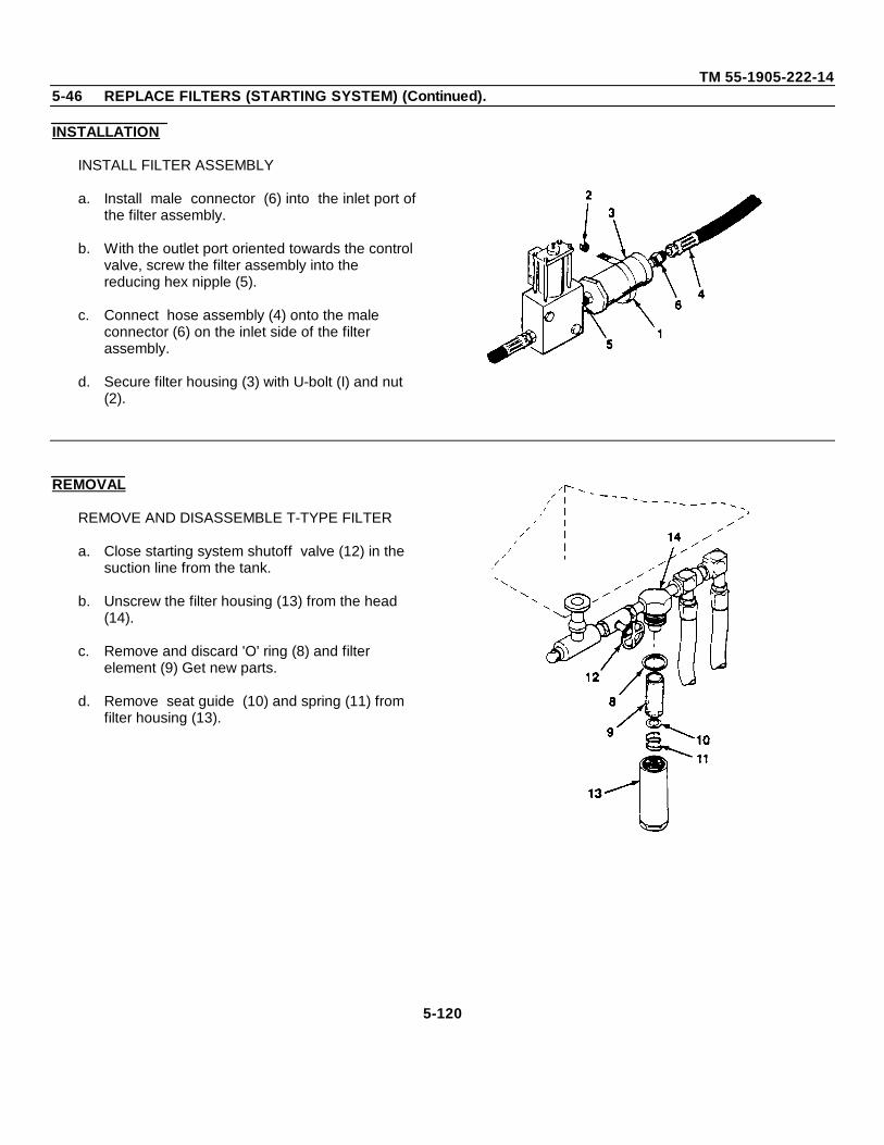
TM 55-1905-222-145-46 REPLACE FILTERS (STARTING SYSTEM) (Continued).
INSTALLATION
INSTALL FILTER ASSEMBLY
a. Install male connector (6) into the inlet port ofthe filter assembly.
b. With the outlet port oriented towards the control valve, screw the filter assembly into the reducing hex nipple (5).
c. Connect hose assembly (4) onto the male connector (6) on the inlet side of the filter assembly.
d. Secure filter housing (3) with U-bolt (I) and nut (2).
REMOVAL
REMOVE AND DISASSEMBLE T-TYPE FILTER
a. Close starting system shutoff valve (12) in the suction line from the tank.
b. Unscrew the filter housing (13) from the head (14).
c. Remove and discard 'O' ring (8) and filter element (9) Get new parts.
d. Remove seat guide (10) and spring (11) from filter housing (13).
5-120
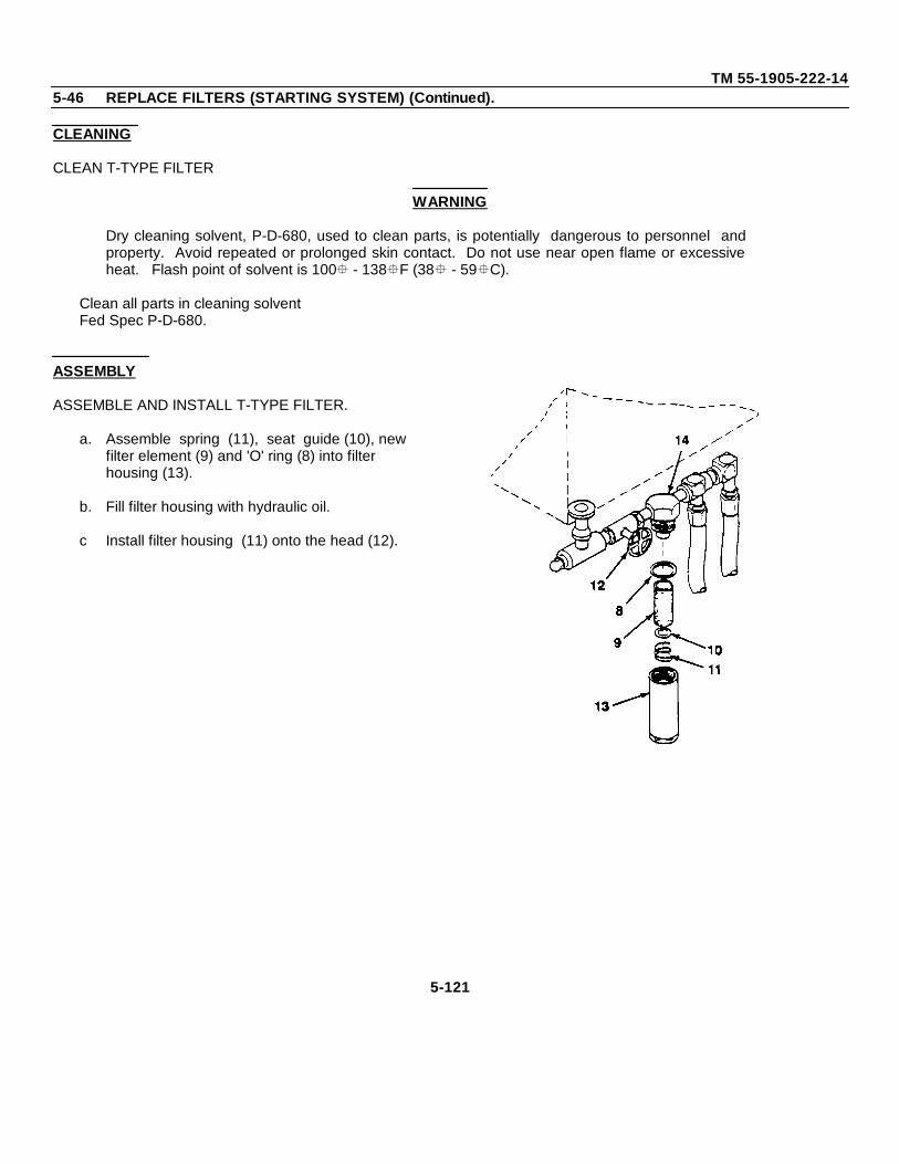
TM 55-1905-222-145-46 REPLACE FILTERS (STARTING SYSTEM) (Continued).
CLEANING
CLEAN T-TYPE FILTER
WARNING
Dry cleaning solvent, P-D-680, used to clean parts, is potentially dangerous to personnel andproperty. Avoid repeated or prolonged skin contact. Do not use near open flame or excessiveheat. Flash point of solvent is 100 - 138F (38 - 59C).
Clean all parts in cleaning solventFed Spec P-D-680.
ASSEMBLY
ASSEMBLE AND INSTALL T-TYPE FILTER.
a. Assemble spring (11), seat guide (10), new filter element (9) and 'O' ring (8) into filter housing (13).
b. Fill filter housing with hydraulic oil.
c Install filter housing (11) onto the head (12).
5-121
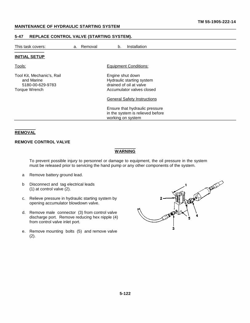
TM 55-1905-222-14MAINTENANCE OF HYDRAULIC STARTING SYSTEM
5-47 REPLACE CONTROL VALVE (STARTING SYSTEM).
This task covers: a. Removal b. Installation
INITIAL SETUP
Tools: Equipment Conditions:
Tool Kit, Mechanic's, Rail Engine shut downand Marine Hydraulic starting system5180-00-629-9783 drained of oil at valve
Torque Wrench Accumulator valves closed
General Safety Instructions
Ensure that hydraulic pressurein the system is relieved beforeworking on system
REMOVAL
REMOVE CONTROL VALVE
WARNING
To prevent possible injury to personnel or damage to equipment, the oil pressure in the systemmust be released prior to servicing the hand pump or any other components of the system.
a Remove battery ground lead.
b Disconnect and tag electrical leads(1) at control valve (2).
c. Relieve pressure in hydraulic starting system by opening accumulator blowdown valve.
d. Remove male connector (3) from control valvedischarge port. Remove reducing hex nipple (4)from control valve inlet port.
e. Remove mounting bolts (5) and remove valve(2).
5-122
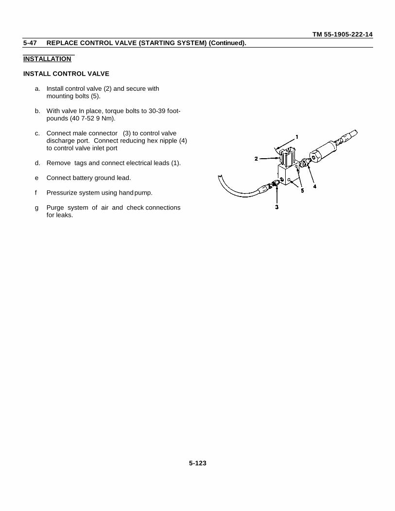
TM 55-1905-222-145-47 REPLACE CONTROL VALVE (STARTING SYSTEM) (Continued).
INSTALLATION
INSTALL CONTROL VALVE
a. Install control valve (2) and secure with mounting bolts (5).
b. With valve In place, torque bolts to 30-39 foot-pounds (40 7-52 9 Nm).
c. Connect male connector (3) to control valve discharge port. Connect reducing hex nipple (4)to control valve inlet port
d. Remove tags and connect electrical leads (1).
e Connect battery ground lead.
f Pressurize system using hand pump.
g Purge system of air and check connections for leaks.
5-123
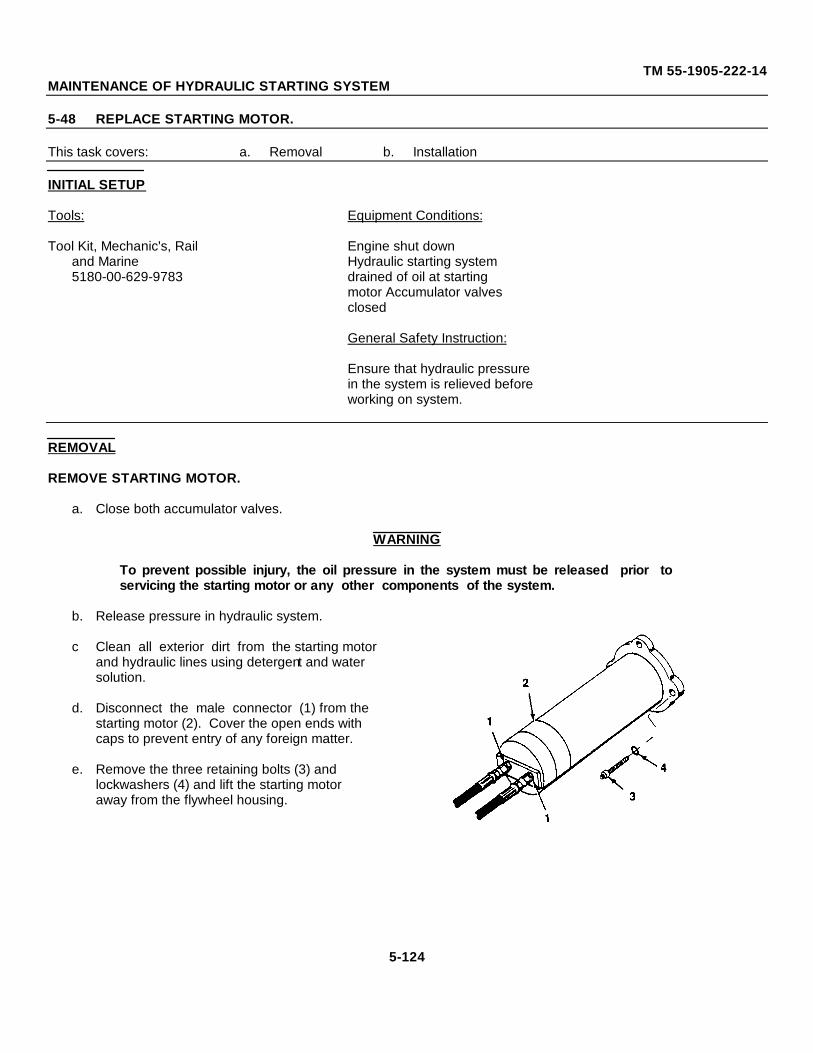
TM 55-1905-222-14MAINTENANCE OF HYDRAULIC STARTING SYSTEM
5-48 REPLACE STARTING MOTOR.
This task covers: a. Removal b. Installation
INITIAL SETUP
Tools: Equipment Conditions:
Tool Kit, Mechanic's, Rail Engine shut downand Marine Hydraulic starting system5180-00-629-9783 drained of oil at starting
motor Accumulator valvesclosed
General Safety Instruction:
Ensure that hydraulic pressurein the system is relieved beforeworking on system.
REMOVAL
REMOVE STARTING MOTOR.
a. Close both accumulator valves.
WARNING
To prevent possible injury, the oil pressure in the system must be released prior toservicing the starting motor or any other components of the system.
b. Release pressure in hydraulic system.
c Clean all exterior dirt from the starting motor and hydraulic lines using detergent and water solution.
d. Disconnect the male connector (1) from the starting motor (2). Cover the open ends with caps to prevent entry of any foreign matter.
e. Remove the three retaining bolts (3) and lockwashers (4) and lift the starting motoraway from the flywheel housing.
5-124
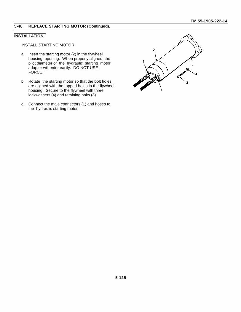
TM 55-1905-222-145-48 REPLACE STARTING MOTOR (Continued).
INSTALLATION
INSTALL STARTING MOTOR
a. Insert the starting motor (2) in the flywheel housing opening. When properly aligned, the pilot diameter of the hydraulic starting motor adapter will enter easily. DO NOT USE FORCE.
b. Rotate the starting motor so that the bolt holes are aligned with the tapped holes in the flywheelhousing. Secure to the flywheel with three lockwashers (4) and retaining bolts (3).
c. Connect the male connectors (1) and hoses to the hydraulic starting motor.
5-125
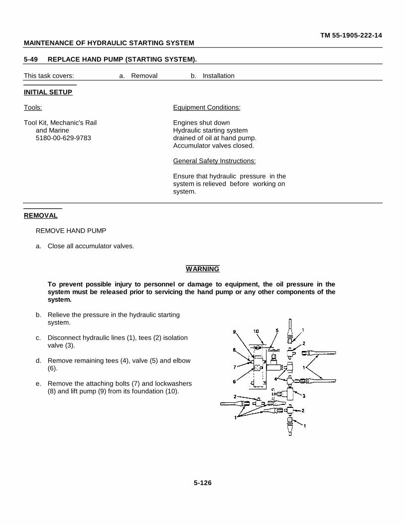
TM 55-1905-222-14MAINTENANCE OF HYDRAULIC STARTING SYSTEM
5-49 REPLACE HAND PUMP (STARTING SYSTEM).
This task covers: a. Removal b. Installation
INITIAL SETUP
Tools: Equipment Conditions:
Tool Kit, Mechanic's Rail Engines shut downand Marine Hydraulic starting system5180-00-629-9783 drained of oil at hand pump.
Accumulator valves closed.
General Safety Instructions:
Ensure that hydraulic pressure in thesystem is relieved before working onsystem.
REMOVAL
REMOVE HAND PUMP
a. Close all accumulator valves.
WARNING
To prevent possible injury to personnel or damage to equipment, the oil pressure in thesystem must be released prior to servicing the hand pump or any other components of thesystem.
b. Relieve the pressure in the hydraulic starting system.
c. Disconnect hydraulic lines (1), tees (2) isolation valve (3).
d. Remove remaining tees (4), valve (5) and elbow(6).
e. Remove the attaching bolts (7) and lockwashers(8) and lift pump (9) from its foundation (10).
5-126
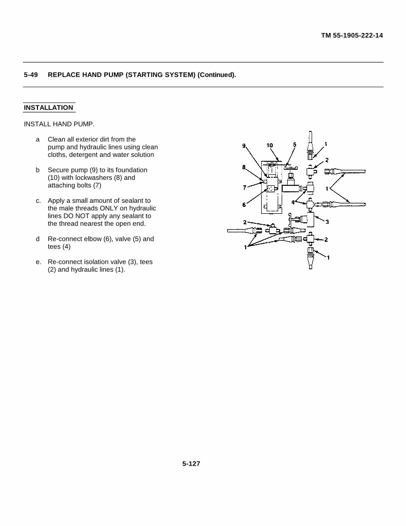
TM 55-1905-222-14
5-49 REPLACE HAND PUMP (STARTING SYSTEM) (Continued).
INSTALLATION
INSTALL HAND PUMP.
a Clean all exterior dirt from thepump and hydraulic lines using cleancloths, detergent and water solution
b Secure pump (9) to its foundation(10) with lockwashers (8) andattaching bolts (7)
c. Apply a small amount of sealant tothe male threads ONLY on hydrauliclines DO NOT apply any sealant tothe thread nearest the open end.
d Re-connect elbow (6), valve (5) andtees (4)
e. Re-connect isolation valve (3), tees(2) and hydraulic lines (1).
5-127
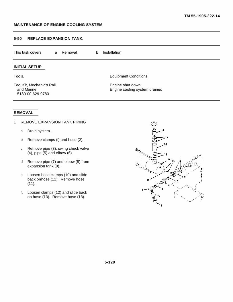
TM 55-1905-222-14
MAINTENANCE OF ENGINE COOLING SYSTEM
5-50 REPLACE EXPANSION TANK.
This task covers a Removal b Installation
INITIAL SETUP
Tools. Equipment Conditions
Tool Kit, Mechanic's Rail Engine shut downand Marine Engine cooling system drained5180-00-629-9783
REMOVAL
1 REMOVE EXPANSION TANK PIPING
a Drain system.
b Remove clamps (I) and hose (2).
c Remove pipe (3), swing check valve(4), pipe (5) and elbow (6).
d Remove pipe (7) and elbow (8) fromexpansion tank (9).
e Loosen hose clamps (10) and slideback onhose (11). Remove hose(11).
f. Loosen clamps (12) and slide backon hose (13). Remove hose (13).
5-128
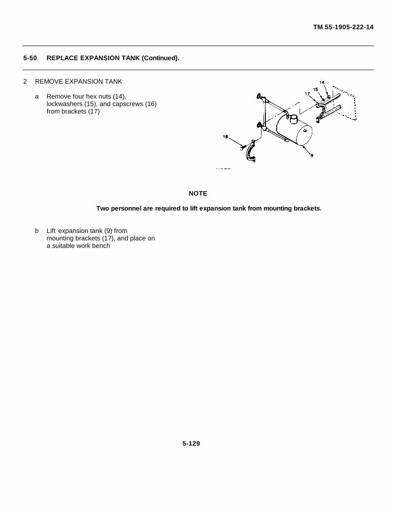
TM 55-1905-222-14
5-50 REPLACE EXPANSION TANK (Continued).
2 REMOVE EXPANSION TANK
a Remove four hex nuts (14),lockwashers (15), and capscrews (16)from brackets (17)
NOTE
Two personnel are required to lift expansion tank from mounting brackets.
b Lift expansion tank (9) frommounting brackets (17), and place ona suitable work bench
5-129
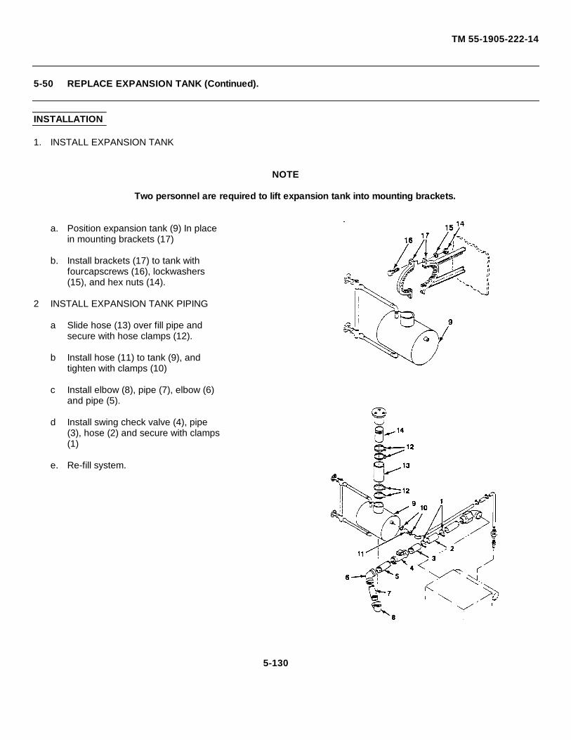
TM 55-1905-222-14
5-50 REPLACE EXPANSION TANK (Continued).
INSTALLATION
1. INSTALL EXPANSION TANK
NOTE
Two personnel are required to lift expansion tank into mounting brackets.
a. Position expansion tank (9) In placein mounting brackets (17)
b. Install brackets (17) to tank withfourcapscrews (16), lockwashers(15), and hex nuts (14).
2 INSTALL EXPANSION TANK PIPING
a Slide hose (13) over fill pipe andsecure with hose clamps (12).
b Install hose (11) to tank (9), andtighten with clamps (10)
c Install elbow (8), pipe (7), elbow (6)and pipe (5).
d Install swing check valve (4), pipe(3), hose (2) and secure with clamps(1)
e. Re-fill system.
5-130
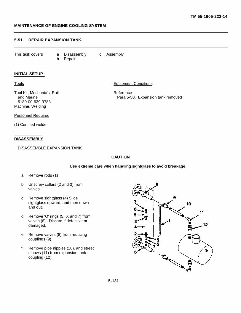
TM 55-1905-222-14
MAINTENANCE OF ENGINE COOLING SYSTEM
5-51 REPAIR EXPANSION TANK.
This task covers a Disassembly c Assemblyb Repair
INITIAL SETUP
Tools Equipment Conditions
Tool Kit, Mechanic's, Rail Referenceand Marine Para 5-50. Expansion tank removed5180-00-629-9783
Machine, Welding
Personnel Required
(1) Certified welder
DISASSEMBLY
DISASSEMBLE EXPANSION TANK
CAUTION
Use extreme care when handling sightglass to avoid breakage.
a. Remove rods (1)
b. Unscrew collars (2 and 3) fromvalves
c Remove sightglass (4) Slidesightglass upward, and then downand out.
d Remove 'O' rings (5, 6, and 7) fromvalves (8). Discard if defective ordamaged.
e Remove valves (8) from reducingcouplings (9)
f. Remove pipe nipples (10), and streetelbows (11) from expansion tankcoupling (12).
5-131
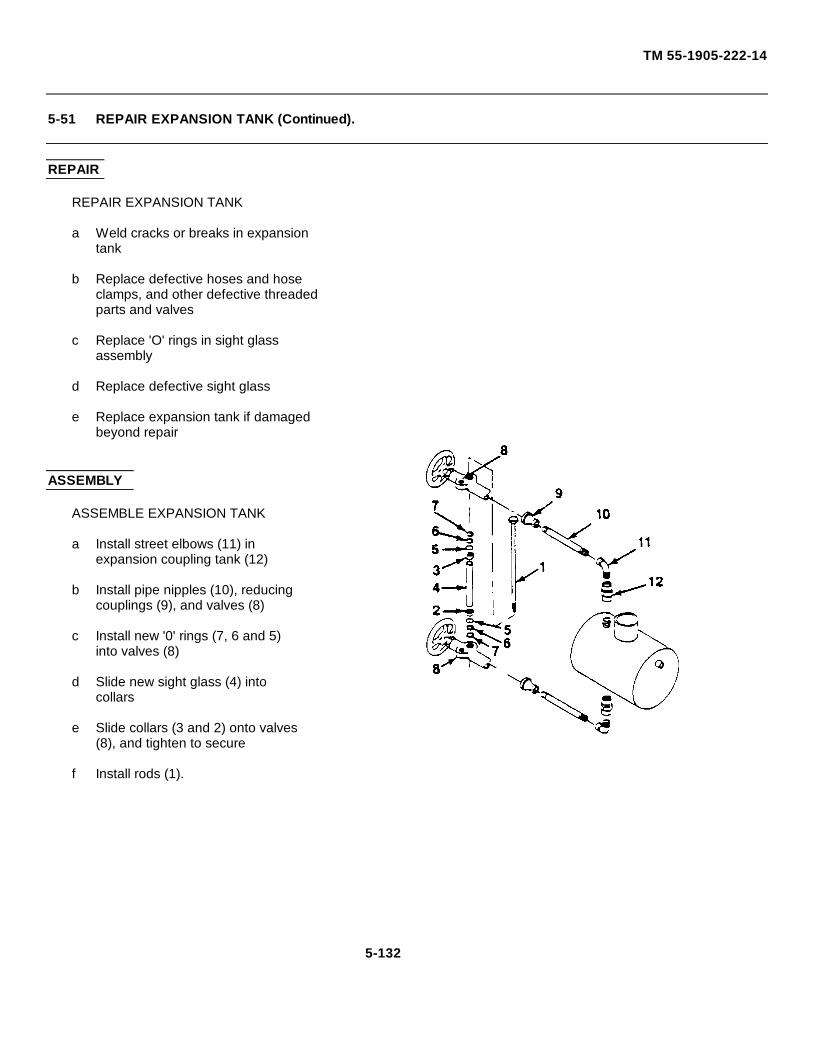
TM 55-1905-222-14
5-51 REPAIR EXPANSION TANK (Continued).
REPAIR
REPAIR EXPANSION TANK
a Weld cracks or breaks in expansiontank
b Replace defective hoses and hoseclamps, and other defective threadedparts and valves
c Replace 'O' rings in sight glassassembly
d Replace defective sight glass
e Replace expansion tank if damagedbeyond repair
ASSEMBLY
ASSEMBLE EXPANSION TANK
a Install street elbows (11) inexpansion coupling tank (12)
b Install pipe nipples (10), reducingcouplings (9), and valves (8)
c Install new '0' rings (7, 6 and 5)into valves (8)
d Slide new sight glass (4) intocollars
e Slide collars (3 and 2) onto valves(8), and tighten to secure
f Install rods (1).
5-132

CHAPTER 6
INTERMEDIATE GENERAL SUPPORT MAINTENANCE
Paragraph
Align Propeller and Propeller Shaft ................................ ................................ ................................ .....................6-24Common Tools and Equipment................................ ................................ ................................ ........................... 6-1Inspect and Replace Anodes................................ ................................ ................................ ............................... 6-27Inspect and Service Propeller and Propeller Shaft ................................. ................................ ............................. 6-21Inspect, Service, Test, Replace and Repair Keel Cooler................................ ................................ ...................... 6-26Repair Accumulator................................ ................................ ................................ ................................ .............6-18Repair Alternator................................ ................................ ................................ ................................ .................6-5Repair Counterbalance Valve................................ ................................ ................................ .............................. 6-16Repair Flow Divider................................ ................................ ................................ ................................ .............6-15Repair Hand Pump (Starting System)................................ ................................ ................................ ..................6-20Repair Helm Unit................................ ................................ ................................ ................................ .................6-14Repair Parts 6-3Repair Propeller and Propeller Shaft................................ ................................ ................................ ...................6-23Repair Ramp Hoist Control Valve................................ ................................ ................................ ........................ 6-7Repair Ramp Hoist Hand Pump . ................................ ................................ ................................ ........................ 6-8Repair Ramp Hoist Hydraulic Pump................................ ................................ ................................ ....................6-6Repair Ramp Locking Hydraulic Cylinder ................................ ................................ ................................ ...........6-9Repair Ramp Sheaves and Latch Mechanism................................ ................................ ................................ .....6-11Repair Ramp Winch................................. ................................ ................................ ................................ ...........6-10Repair Recharging Pump................................ ................................ ................................ ................................ ....6-17Repair Starting Motor. ................................ ................................ ................................ ................................ .........6-19Repair Steering Cylinders ................................ ................................ ................................ ................................ ...6-13Repair Steering Pump................................ ................................ ................................ ................................ .........6-12Repair Stuffing Box................................. ................................ ................................ ................................ ............6-25Replace Propeller and Propeller Shaft................................ ................................ ................................ .................6-22Special Tools, TMDE and Support Equipment................................ ................................ ................................ .....6-2Troubleshooting Procedures................................ ................................ ................................ ................................ 6-4
6-1
TM 55-1905-222-14
Section I. REPAIR PARTS; SPECIAL TOOLS; TEST, NMEASURENMENT, ANDDIAGNOSTIC EQUIPMENT (TMDE); AND SUPPORT EQUIPIE NT
6-1 COMMON TOOLS AND EQUIPMENT.
For authorized common tools and equipment, refer to the Modified Table of Organizational Equipment (MTOE)applicable to your unit.
6-2 SPECIAL TOOLS, TMDE, AND SUPPORT EQUIPMENT.
Any special tools or equipment required by general support maintenance personnel to perform maintenance on thelanding craft is listed in Appendix B of this manual
6-3 REPAIR PARTS.
Repair parts are listed and illustrated In the repair parts and special tools list (TM 55-1905-222-24P) covering generalsupport maintenance of this equipment
Section II. TROUBLESHOOTING
6-4 TROUBLESHOOTING PROCEDURES.
This paragraph provides information useful in diagnosing and correcting unsatisfactory operation or failure of LCM-8systems and equipment Troubleshooting procedures in this manual are limited to the basic craft. Refer to TM 5-2815-231-14 for engine and transmission troubleshooting procedures. Before using the troubleshooting procedures, ensurethat all applicable operating procedures have been performed
NOTE
The table lists the malfunctions which may occur during the service life ofthe equipment. Replace all defective parts when repairing an equipmentunless machining or other repair process can return the part to reusablecondition.
6-2
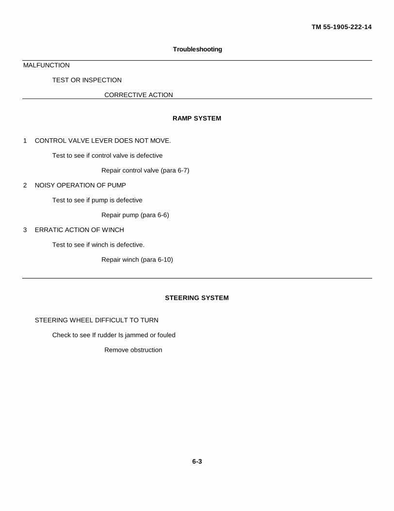
TM 55-1905-222-14
Troubleshooting
MALFUNCTION
TEST OR INSPECTION
CORRECTIVE ACTION
RAMP SYSTEM
1 CONTROL VALVE LEVER DOES NOT MOVE.
Test to see if control valve is defective
Repair control valve (para 6-7)
2 NOISY OPERATION OF PUMP
Test to see if pump is defective
Repair pump (para 6-6)
3 ERRATIC ACTION OF WINCH
Test to see if winch is defective.
Repair winch (para 6-10)
STEERING SYSTEM
STEERING WHEEL DIFFICULT TO TURN
Check to see If rudder Is jammed or fouled
Remove obstruction
6-3
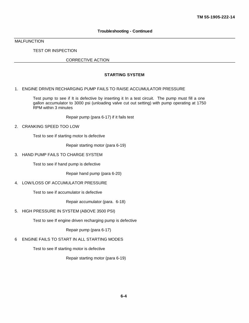
TM 55-1905-222-14
Troubleshooting - Continued
MALFUNCTION
TEST OR INSPECTION
CORRECTIVE ACTION
STARTING SYSTEM
1. ENGINE DRIVEN RECHARGING PUMP FAILS TO RAISE ACCUMULATOR PRESSURE
Test pump to see if It is defective by inserting it In a test circuit. The pump must fill a onegallon accumulator to 3000 psi (unloading valve cut out setting) with pump operating at 1750RPM within 3 minutes
Repair pump (para 6-17) if it fails test
2. CRANKING SPEED TOO LOW
Test to see if starting motor Is defective
Repair starting motor (para 6-19)
3. HAND PUMP FAILS TO CHARGE SYSTEM
Test to see if hand pump is defective
Repair hand pump (para 6-20)
4. LOW/LOSS OF ACCUMULATOR PRESSURE
Test to see if accumulator is defective
Repair accumulator (para. 6-18)
5. HIGH PRESSURE IN SYSTEM (ABOVE 3500 PSI)
Test to see If engine driven recharging pump is defective
Repair pump (para 6-17)
6 ENGINE FAILS TO START IN ALL STARTING MODES
Test to see If starting motor is defective
Repair starting motor (para 6-19)
6-4
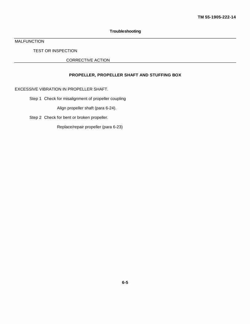
TM 55-1905-222-14
Troubleshooting
MALFUNCTION
TEST OR INSPECTION
CORRECTIVE ACTION
PROPELLER, PROPELLER SHAFT AND STUFFING BOX
EXCESSIVE VIBRATION IN PROPELLER SHAFT.
Step 1 Check for misalignment of propeller coupling
Align propeller shaft (para 6-24).
Step 2 Check for bent or broken propeller.
Replace/repair propeller (para 6-23)
6-5
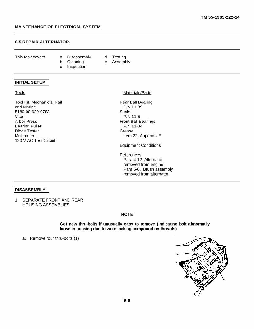
TM 55-1905-222-14
MAINTENANCE OF ELECTRICAL SYSTEM
6-5 REPAIR ALTERNATOR.
This task covers a Disassembly d Testingb Cleaning e Assemblyc Inspection
INITIAL SETUP
Tools Materials/Parts
Tool Kit, Mechanic's, Rail Rear Ball Bearingand Marine P/N 11-395180-00-629-9783 SealsVise P/N 11-5Arbor Press Front Ball BearingsBearing Puller P/N 11-34Diode Tester GreaseMultimeter Item 22, Appendix E120 V AC Test Circuit
Equipment Conditions
ReferencesPara 4-12 Alternatorremoved from enginePara 5-6. Brush assemblyremoved from alternator
DISASSEMBLY
1 SEPARATE FRONT AND REARHOUSING ASSEMBLIES
NOTE
Get new thru-bolts if unusually easy to remove (indicating bolt abnormallyloose in housing due to worn locking compound on threads)
a. Remove four thru-bolts (1)
6-6
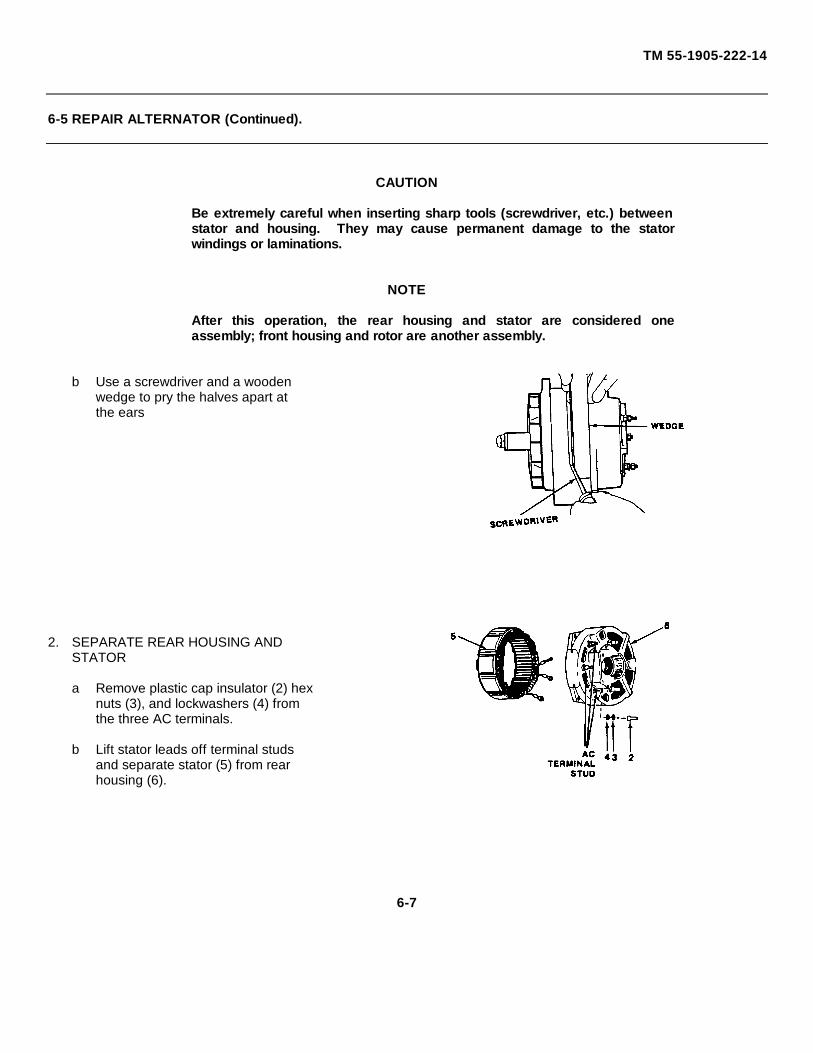
TM 55-1905-222-14
6-5 REPAIR ALTERNATOR (Continued).
CAUTION
Be extremely careful when inserting sharp tools (screwdriver, etc.) betweenstator and housing. They may cause permanent damage to the statorwindings or laminations.
NOTE
After this operation, the rear housing and stator are considered oneassembly; front housing and rotor are another assembly.
b Use a screwdriver and a woodenwedge to pry the halves apart atthe ears
2. SEPARATE REAR HOUSING ANDSTATOR
a Remove plastic cap insulator (2) hexnuts (3), and lockwashers (4) fromthe three AC terminals.
b Lift stator leads off terminal studsand separate stator (5) from rearhousing (6).
6-7
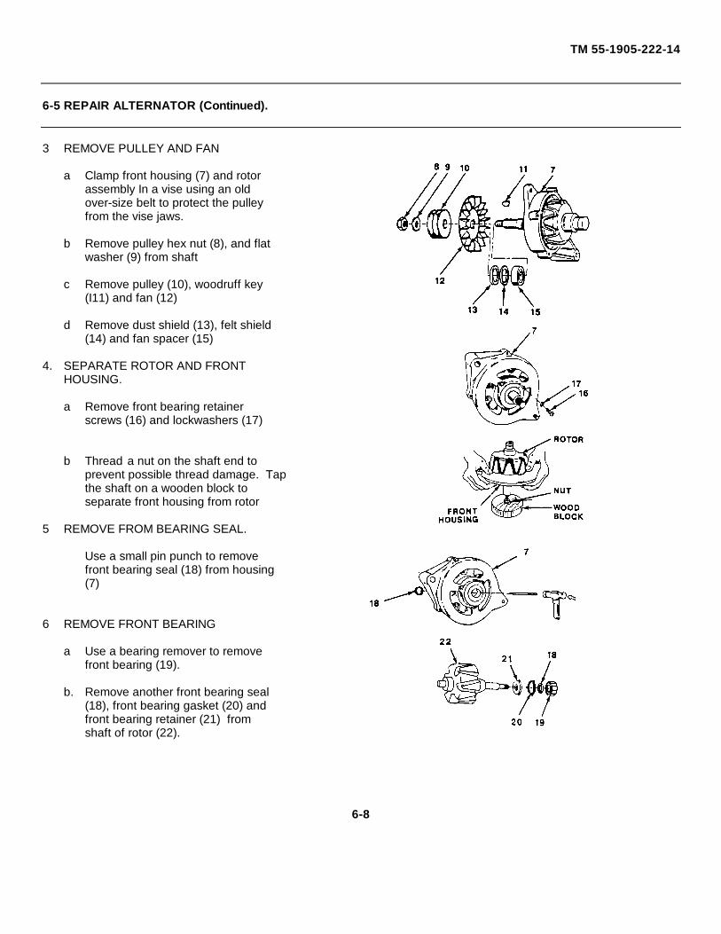
TM 55-1905-222-14
6-5 REPAIR ALTERNATOR (Continued).
3 REMOVE PULLEY AND FAN
a Clamp front housing (7) and rotorassembly In a vise using an oldover-size belt to protect the pulleyfrom the vise jaws.
b Remove pulley hex nut (8), and flatwasher (9) from shaft
c Remove pulley (10), woodruff key(I11) and fan (12)
d Remove dust shield (13), felt shield(14) and fan spacer (15)
4. SEPARATE ROTOR AND FRONTHOUSING.
a Remove front bearing retainerscrews (16) and lockwashers (17)
b Thread a nut on the shaft end toprevent possible thread damage. Tapthe shaft on a wooden block toseparate front housing from rotor
5 REMOVE FROM BEARING SEAL.
Use a small pin punch to removefront bearing seal (18) from housing(7)
6 REMOVE FRONT BEARING
a Use a bearing remover to removefront bearing (19).
b. Remove another front bearing seal(18), front bearing gasket (20) andfront bearing retainer (21) fromshaft of rotor (22).
6-8
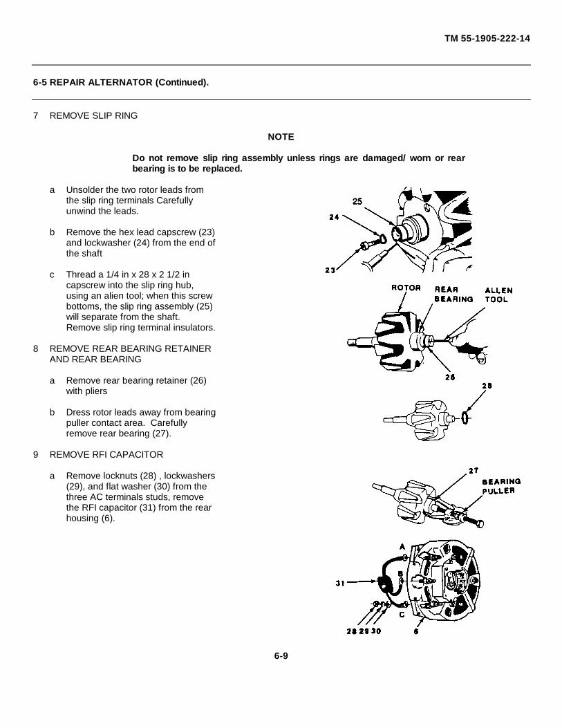
TM 55-1905-222-14
6-5 REPAIR ALTERNATOR (Continued).
7 REMOVE SLIP RING
NOTE
Do not remove slip ring assembly unless rings are damaged/ worn or rearbearing is to be replaced.
a Unsolder the two rotor leads fromthe slip ring terminals Carefullyunwind the leads.
b Remove the hex lead capscrew (23)and lockwasher (24) from the end ofthe shaft
c Thread a 1/4 in x 28 x 2 1/2 incapscrew into the slip ring hub,using an alien tool; when this screwbottoms, the slip ring assembly (25)will separate from the shaft.Remove slip ring terminal insulators.
8 REMOVE REAR BEARING RETAINERAND REAR BEARING
a Remove rear bearing retainer (26)with pliers
b Dress rotor leads away from bearingpuller contact area. Carefullyremove rear bearing (27).
9 REMOVE RFI CAPACITOR
a Remove locknuts (28) , lockwashers(29), and flat washer (30) from thethree AC terminals studs, removethe RFI capacitor (31) from the rearhousing (6).
6-9
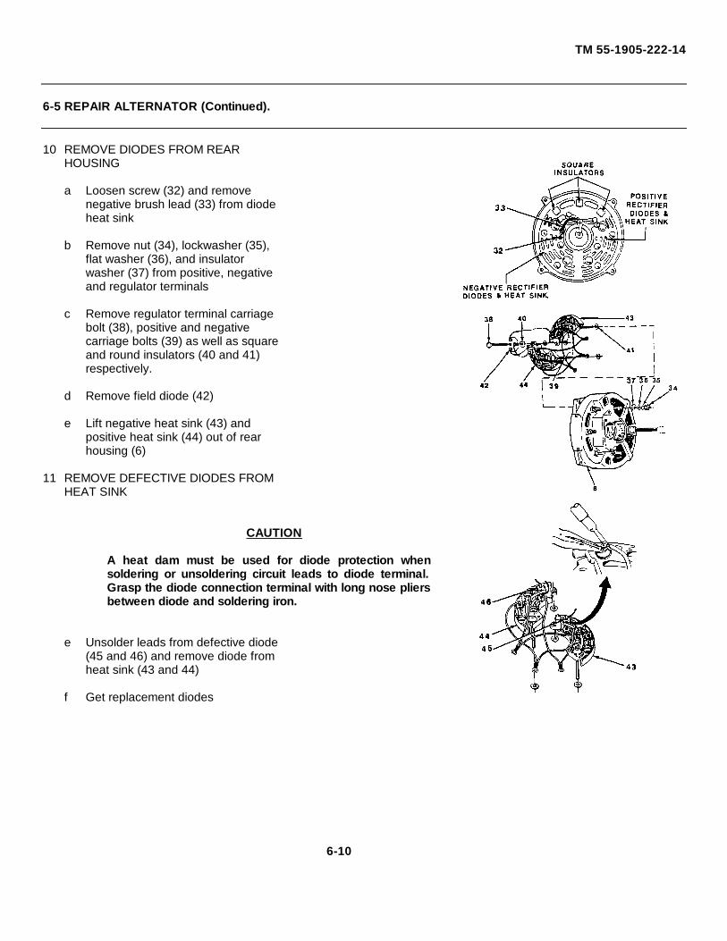
TM 55-1905-222-14
6-5 REPAIR ALTERNATOR (Continued).
10 REMOVE DIODES FROM REARHOUSING
a Loosen screw (32) and removenegative brush lead (33) from diodeheat sink
b Remove nut (34), lockwasher (35),flat washer (36), and insulatorwasher (37) from positive, negativeand regulator terminals
c Remove regulator terminal carriagebolt (38), positive and negativecarriage bolts (39) as well as squareand round insulators (40 and 41)respectively.
d Remove field diode (42)
e Lift negative heat sink (43) andpositive heat sink (44) out of rearhousing (6)
11 REMOVE DEFECTIVE DIODES FROMHEAT SINK
CAUTION
A heat dam must be used for diode protection whensoldering or unsoldering circuit leads to diode terminal.Grasp the diode connection terminal with long nose pliersbetween diode and soldering iron.
e Unsolder leads from defective diode(45 and 46) and remove diode fromheat sink (43 and 44)
f Get replacement diodes
6-10
TM 55-1905-222-14
6-5 REPAIR ALTERNATOR (Continued).
CLEANING
CLEAN ALTERNATOR COMPONENTS.
a Wipe front bearing seals with aclean lint-free cloth to removeforeign material and old grease
CAUTION
Do not use compressed air on rotor or stator windings. Undetectable flawsmay be created, making the assembly less than acceptable.
b Wipe off stator and rotor with aclean lint-free cloth
c Clean front housing, rear housing,fan, and pulley with a clean lint-free cloth
WARNING
Dry cleaning solvent, P-D-680, used to clean parts, is potentially dangerousto personnel and property. Avoid repeated or prolonged skin contact. Do notuse near open flame or excessive heat. Flash point of solvent is 100°-138°F (38°- 59°C).
d. Clean ball bearings, retainers andwashers in solvent P-D-680 andallow to air dry
e Clean brush contacting surfaces ofslip rings with fine crocus cloth toremove minor roughness. Replaceslip ring assembly If necessary.
6-11
TM 55-1905-222-14
6-5 REPAIR ALTERNATOR (Continued).
INSPECTION
1 INSPECT STATOR ASSEMBLY
Inspect stator assembly for physicaldamage. Look for evidence of therotor striking lamination, brokenInsulation and foreign material thatmay restrict circulation of coolingair Discoloration of the wireenamel is evidence of overheatingthatmay result in a shorted orgrounded wiring
2 INSPECT FAN AND PULLEY
Inspect fan for bent fins, loosewelds or excessive wear Checkdrive surfaces and bore of pulley forwear. Replace if necessary
3 INSPECT BEARING SEALS ANDGASKETS
Inspect front bearing seals andgaskets for tear or other damageReplace if necessary
4 INSPECT ROTOR
a Inspect rotor for stripped threads onshaft, worn key slot, scuffed polefinger or bent shaft
b Replace rotor assembly if any of theabove defects are noted (Newrotors include a new rear bearingand slip rings as part of theassembly).
5 INSPECT BEARINGS
a Inspect bearing surfaces for wear
b Rotate the innerrace to see ifbearings turn freely
6-12
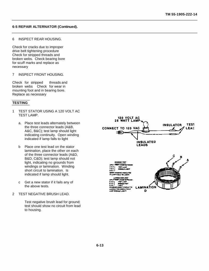
TM 55-1905-222-14
6-5 REPAIR ALTERNATOR (Continued).
6 INSPECT REAR HOUSING.
Check for cracks due to improperdrive belt tightening procedureCheck for stripped threads andbroken webs. Check bearing borefor scuff marks and replace asnecessary
7 INSPECT FRONT HOUSING.
Check for stripped threads andbroken webs Check for wear inmounting foot and in bearing bore.Replace as necessary
TESTING
1 TEST STATOR USING A 120 VOLT ACTEST LAMP.
a. Place test leads alternately betweenthe three connector leads (A&B,A&C, B&C); test lamp should lightindicating continuity. Open windingindicated if lamp falls to light
b Place one test lead on the statorlamination, place the other on eachof the three connector leads (A&D,B&D, C&D); test lamp should notlight, indicating no grounds fromwindings or lamination. Windingshort circuit to lamination. Isindicated if lamp should light.
c Get a new stator if it fails any ofthe above tests.
2 TEST NEGATIVE BRUSH LEAD.
Test negative brush lead for ground;test should show no circuit from leadto housing.
6-13
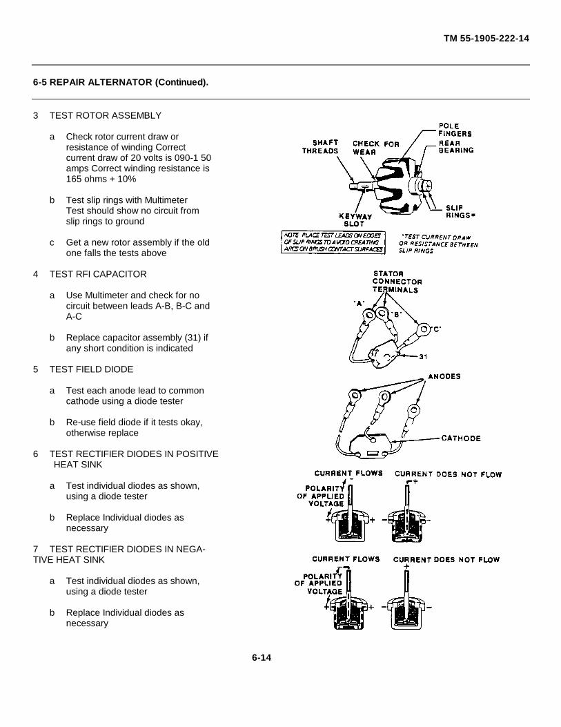
TM 55-1905-222-14
6-5 REPAIR ALTERNATOR (Continued).
3 TEST ROTOR ASSEMBLY
a Check rotor current draw orresistance of winding Correctcurrent draw of 20 volts is 090-1 50amps Correct winding resistance is165 ohms + 10%
b Test slip rings with MultimeterTest should show no circuit fromslip rings to ground
c Get a new rotor assembly if the oldone falls the tests above
4 TEST RFI CAPACITOR
a Use Multimeter and check for nocircuit between leads A-B, B-C andA-C
b Replace capacitor assembly (31) ifany short condition is indicated
5 TEST FIELD DIODE
a Test each anode lead to commoncathode using a diode tester
b Re-use field diode if it tests okay,otherwise replace
6 TEST RECTIFIER DIODES IN POSITIVEHEAT SINK
a Test individual diodes as shown,using a diode tester
b Replace Individual diodes asnecessary
7 TEST RECTIFIER DIODES IN NEGA-TIVE HEAT SINK
a Test individual diodes as shown,using a diode tester
b Replace Individual diodes asnecessary
6-14
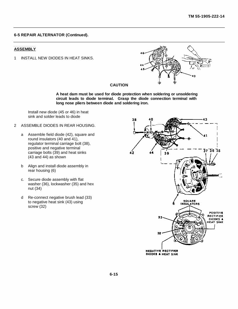
TM 55-1905-222-14
6-5 REPAIR ALTERNATOR (Continued).
ASSEMBLY
1 INSTALL NEW DIODES IN HEAT SINKS.
CAUTION
A heat dam must be used for diode protection when soldering or unsolderingcircuit leads to diode terminal. Grasp the diode connection terminal withlong nose pliers between diode and soldering iron.
Install new diode (45 or 46) in heatsink and solder leads to diode
2 ASSEMBLE DIODES IN REAR HOUSING.
a Assemble field diode (42), square andround insulators (40 and 41),regulator terminal carriage bolt (38),positive and negative terminalcarriage bolts (39) and heat sinks(43 and 44) as shown
b Align and install diode assembly inrear housing (6)
c. Secure diode assembly with flatwasher (36), lockwasher (35) and hexnut (34)
d Re-connect negative brush lead (33)to negative heat sink (43) usingscrew (32)
6-15
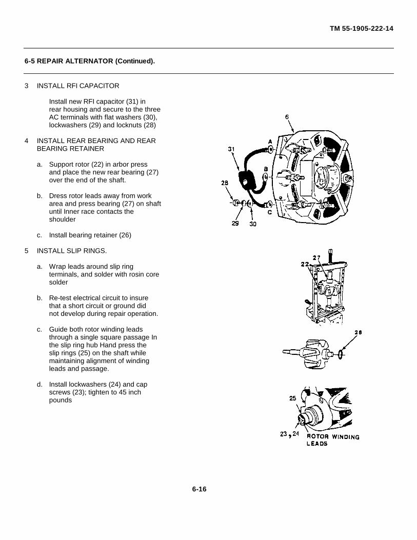
TM 55-1905-222-14
6-5 REPAIR ALTERNATOR (Continued).
3 INSTALL RFI CAPACITOR
Install new RFI capacitor (31) inrear housing and secure to the threeAC terminals with flat washers (30),lockwashers (29) and locknuts (28)
4 INSTALL REAR BEARING AND REARBEARING RETAINER
a. Support rotor (22) in arbor pressand place the new rear bearing (27)over the end of the shaft.
b. Dress rotor leads away from workarea and press bearing (27) on shaftuntil Inner race contacts theshoulder
c. Install bearing retainer (26)
5 INSTALL SLIP RINGS.
a. Wrap leads around slip ringterminals, and solder with rosin coresolder
b. Re-test electrical circuit to insurethat a short circuit or ground didnot develop during repair operation.
c. Guide both rotor winding leadsthrough a single square passage Inthe slip ring hub Hand press theslip rings (25) on the shaft whilemaintaining alignment of windingleads and passage.
d. Install lockwashers (24) and capscrews (23); tighten to 45 inchpounds
6-16
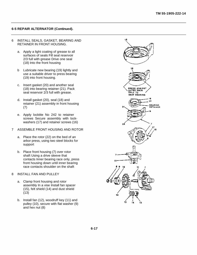
TM 55-1905-222-14
6-5 REPAIR ALTERNATOR (Continued).
6 INSTALL SEALS, GASKET, BEARING ANDRETAINER IN FRONT HOUSING.
a. Apply a light coating of grease to allsurfaces of seals Fill seal reservoir2/3 full with grease Drive one seal(18) Into the front housing
b Lubricate new bearing (19) lightly anduse a suitable driver to press bearing(19) into front housing.
c. Insert gasket (20) and another seal(18) into bearing retainer (21). Packseal reservoir 2/3 full with grease.
d. Install gasket (20), seal (18) andretainer (21) assembly in front housing(7)
e. Apply locktite No 242 to retainerscrews Secure assembly with lock-washers (17) and retainer screws (16)
7 ASSEMBLE FRONT HOUSING AND ROTOR
a. Place the rotor (22) on the bed of anarbor press, using two steel blocks forsupport
b. Place front housing (7) over rotorshaft Using a drive sleeve thatcontacts Inner bearing race only, pressfront housing down until inner bearingrace contacts shoulder on the shaft
8 INSTALL FAN AND PULLEY
a. Clamp front housing and rotorassembly In a vise Install fan spacer(15), felt shield (14) and dust shield(13)
b. Install fan (12), woodruff key (11) andpulley (10), secure with flat washer (9)and hex nut (8)
6-17
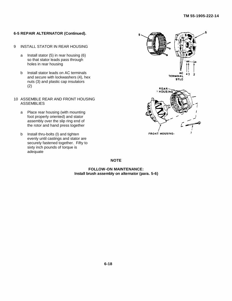
TM 55-1905-222-14
6-5 REPAIR ALTERNATOR (Continued).
9 INSTALL STATOR IN REAR HOUSING
a Install stator (5) in rear housing (6)so that stator leads pass throughholes in rear housing
b Install stator leads on AC terminalsand secure with lockwashers (4), hexnuts (3) and plastic cap insulators(2)
10 ASSEMBLE REAR AND FRONT HOUSINGASSEMBLIES
a Place rear housing (with mountingfoot properly oriented) and statorassembly over the slip ring end ofthe rotor and hand press together
b Install thru-bolts (I) and tightenevenly until castings and stator aresecurely fastened together. Fifty tosixty inch pounds of torque isadequate
NOTE
FOLLOW-ON MAINTENANCE:Install brush assembly on alternator (para. 5-6)
6-18
TM 55-1905-222-14 CO5
MAINTENANCE OF RAMP HOIST HYDRAULIC PUMP
6-6 REPAIR RAMP HOIST HYDRAULIC PUMP.
This task includes: a Disassembly b. Cleaning c Inspection d Assembly
INITIAL SETUP
Tools Equipment Conditions
Tool Kit, Mechanic's, Rail Referenceand Marine Para 5-16 Pump removed5180-00-629-9783
Arbor PressTorque WrenchSoft Hammer
Materials/PartsCartndge KitP/N 578311
Seal KitP/N 922851
Cleaning SolventItem 17, Appendix E
DISASSEMBLY
DISASSEMBLE RAMP HOIST HYDRAULICPUMP
NOTEInlet cover (2) may need to be rotated to mountinlet hydraulic line
a. Remove cover bolts (1), and cover(2) Note relative position of inlet portIn cover to the outlet port In body forcorrect assembly
b. Grasp the pump cartridge (inner assembly), and while turning, pull it fromdrive shaft Loosening the pump cartridge can be accomplished by pryingunder the flats of the ring with twoscrew drivers.
c. Remove sealing ring (3) from recess inbody
6-19
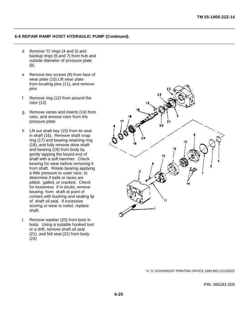
TM 55-1905-222-14
6-6 REPAIR RAMP HOIST HYDRAULIC PUMP (Continued).
d Remove 'O' rings (4 and 5) andbackup rings (6 and 7) from hub andoutside diameter of pressure plate(8).
e Remove two screws (9) from face ofwear plate (10) Lift wear platefrom locating pins (11), and removepins
f Remove ring (12) from around therotor (13)
g. Remove vanes and inserts (14) fromrotor, and remove rotor from thepressure plate
h Lift out shaft key (15) from its seatin shaft (16). Remove shaft snapring (17) and bearing retaining ring(18), and fully remove drive shaftand bearing (19) from body bygently tapping the keyed end ofshaft with a soft hammer. Checkbearing for wear before removing itfrom shaft. Rotate bearing applyinga little pressure to outer race, todetermine if balls or races arepitted, galled, or cracked. Checkfor looseness If in doubt, removebearing from shaft at point ofcontact with bushing and sealing lipof shaft oil seal. If excessivescoring or wear is noted, replaceshaft.
i. Remove washer (20) from bore inbody. Using a suitable hooked toolor a drift, remove shaft oil seal(21), and felt seal (22) from body(23)
*U. S. GOVERKENT PRINTING OFFICE 1995-655-121/20022
PIN: 066281-005
6-20

TM 55-1905-222-14
6-6 REPAIR RAMP HOIST HYDRAULIC PUMP (Continued).
CLEANING
CLEAN ALL PUMP PARTS
WARNING
Dry cleaning solvent, P-D-680, used to clean parts, is potentially dangerousto personnel and property. Avoid repeated or prolonged skin contact. Donot use near open flame or excessive heat. Flash point of solvent is 100° -138°F (38°-59°C).
a Wash all metal parts in cleaningsolvent Fed Spec P-D-680.
b Blow parts dry with filtered,dehydrated air and place them on aclean surface for inspection
INSPECTION
INSPECT RAMP HOIST HYDRAULICPUMP
a Inspect surfaces of wear plate,pressure plate, ring and rotor forscoring and excessive wear. Lightscoring may be carefully stoned orlapped Discard parts that areheavily scored
b Check edges of vanes for wearVanes shall not have excessive playin rotor slots or burrs on edges.
c Inspect inside diameter of bushing(24) Remove bushing if wear orscoring is evident If wear plate isto be replaced, do not removebushing, as a new plate comes withbushing Inserted.
d. Rotate the bearing while applyingpressure to check for wear,looseness and pitted or crackedraces.
6-21
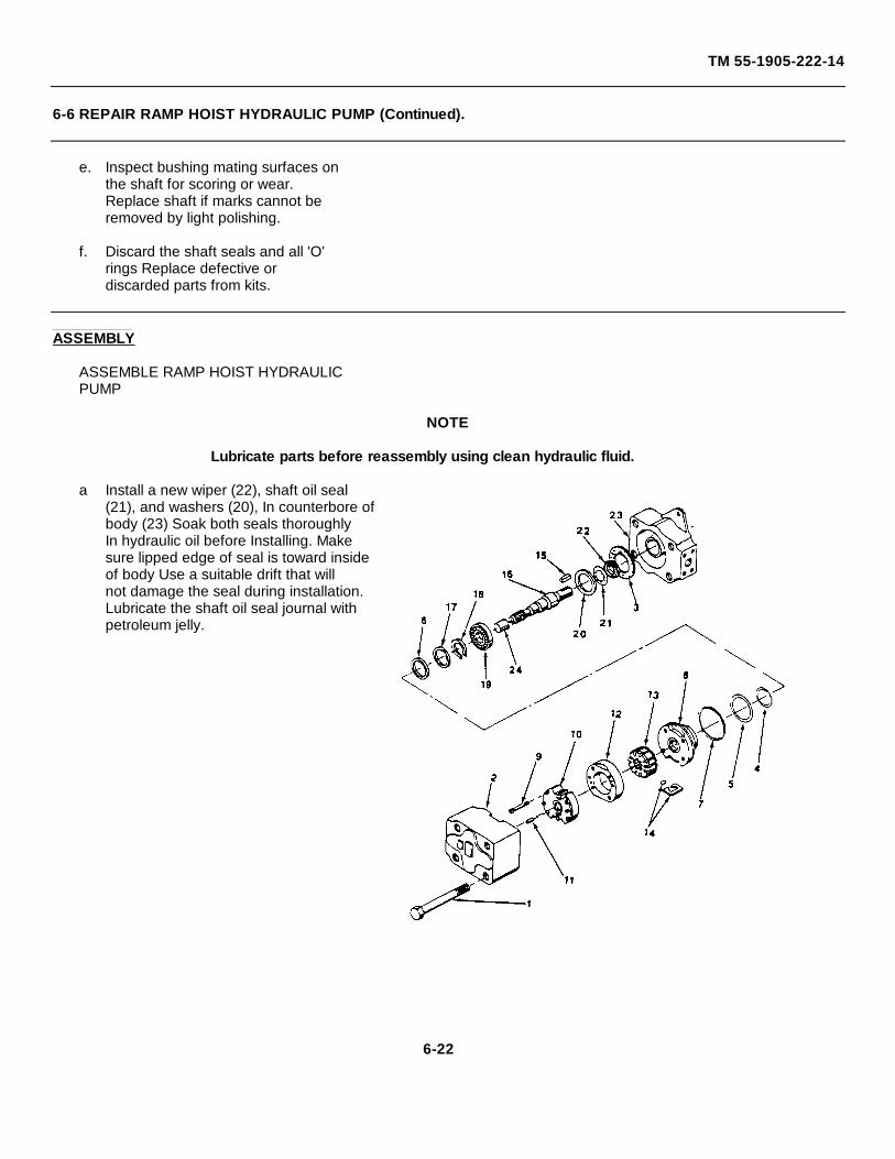
TM 55-1905-222-14
6-6 REPAIR RAMP HOIST HYDRAULIC PUMP (Continued).
e. Inspect bushing mating surfaces onthe shaft for scoring or wear.Replace shaft if marks cannot beremoved by light polishing.
f. Discard the shaft seals and all 'O'rings Replace defective ordiscarded parts from kits.
ASSEMBLY
ASSEMBLE RAMP HOIST HYDRAULICPUMP
NOTE
Lubricate parts before reassembly using clean hydraulic fluid.
a Install a new wiper (22), shaft oil seal(21), and washers (20), In counterbore ofbody (23) Soak both seals thoroughlyIn hydraulic oil before Installing. Makesure lipped edge of seal is toward insideof body Use a suitable drift that willnot damage the seal during installation.Lubricate the shaft oil seal journal withpetroleum jelly.
6-22
TM 55-1905-222-14
6-6 REPAIR RAMP HOIST HYDRAULIC PUMP (Continued).
b Position shaft bearing (19) in placeon drive shaft, being careful not tocock the bearing Using an arborpress, support Inner race of bearingand press bearing against shoulderof shaft (16) Apply tape aroundthe end of the shaft to protect theseal Install shaft and bearing Intobody until bearing is fully seatedIf necessary, gently tap shaft with asoft hammer
c Install shaft snap ring (17), andbearing retaining ring (18) Makesure that both parts are firmlyseated in place Remove tape fromend of shaft (16)
d Install the shaft key (15)
NOTE
Direction of rotation is designated as viewed from the shaft end of pump. R.H. rotation is clockwise; L. H. rotation is counterclockwise.
e Place rotor (13) on pressure plate(8) with arrow point in desireddirection of rotation. Install insertsin vanes (14), and position bothparts in rotor slots The sharpedges of the vanes must be towardthe direction of rotation.
f Install locating pins (11) In pressureplate (8) Install ring (12) overlocating pins against pressure platewith arrow pointing in direction ofshaft rotation. Lubricate rotor (13),and ring with clean hydraulic oil.
6-23
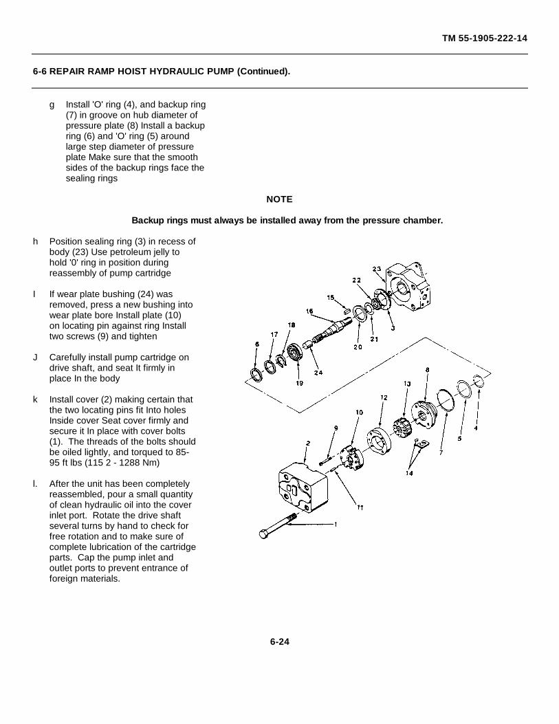
TM 55-1905-222-14
6-6 REPAIR RAMP HOIST HYDRAULIC PUMP (Continued).
g Install 'O' ring (4), and backup ring(7) in groove on hub diameter ofpressure plate (8) Install a backupring (6) and 'O' ring (5) aroundlarge step diameter of pressureplate Make sure that the smoothsides of the backup rings face thesealing rings
NOTE
Backup rings must always be installed away from the pressure chamber.
h Position sealing ring (3) in recess ofbody (23) Use petroleum jelly tohold '0' ring in position duringreassembly of pump cartridge
I If wear plate bushing (24) wasremoved, press a new bushing intowear plate bore Install plate (10)on locating pin against ring Installtwo screws (9) and tighten
J Carefully install pump cartridge ondrive shaft, and seat It firmly inplace In the body
k Install cover (2) making certain thatthe two locating pins fit Into holesInside cover Seat cover firmly andsecure it In place with cover bolts(1). The threads of the bolts shouldbe oiled lightly, and torqued to 85-95 ft lbs (115 2 - 1288 Nm)
l. After the unit has been completelyreassembled, pour a small quantityof clean hydraulic oil into the coverinlet port. Rotate the drive shaftseveral turns by hand to check forfree rotation and to make sure ofcomplete lubrication of the cartridgeparts. Cap the pump inlet andoutlet ports to prevent entrance offoreign materials.
6-24
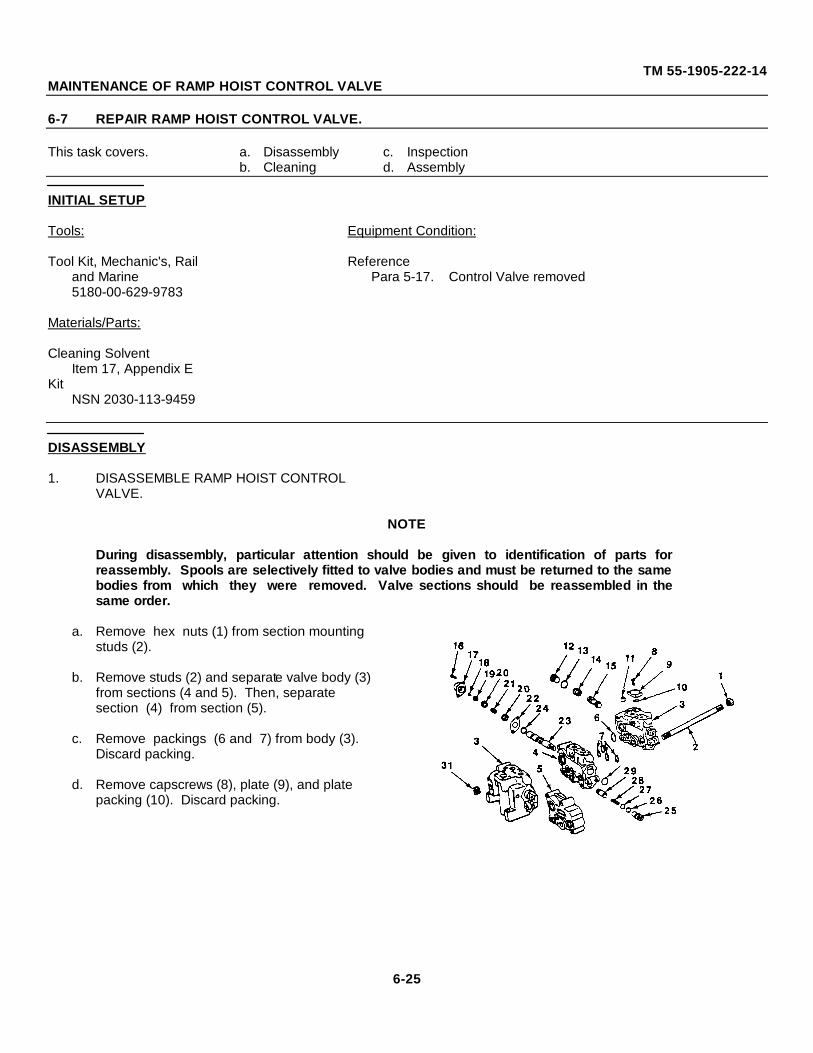
TM 55-1905-222-14MAINTENANCE OF RAMP HOIST CONTROL VALVE
6-7 REPAIR RAMP HOIST CONTROL VALVE.
This task covers. a. Disassembly c. Inspectionb. Cleaning d. Assembly
INITIAL SETUP
Tools: Equipment Condition:
Tool Kit, Mechanic's, Rail Referenceand Marine Para 5-17. Control Valve removed5180-00-629-9783
Materials/Parts:
Cleaning SolventItem 17, Appendix E
KitNSN 2030-113-9459
DISASSEMBLY
1. DISASSEMBLE RAMP HOIST CONTROLVALVE.
NOTE
During disassembly, particular attention should be given to identification of parts forreassembly. Spools are selectively fitted to valve bodies and must be returned to the samebodies from which they were removed. Valve sections should be reassembled in thesame order.
a. Remove hex nuts (1) from section mounting studs (2).
b. Remove studs (2) and separate valve body (3) from sections (4 and 5). Then, separate section (4) from section (5).
c. Remove packings (6 and 7) from body (3). Discard packing.
d. Remove capscrews (8), plate (9), and plate packing (10). Discard packing.
6-25
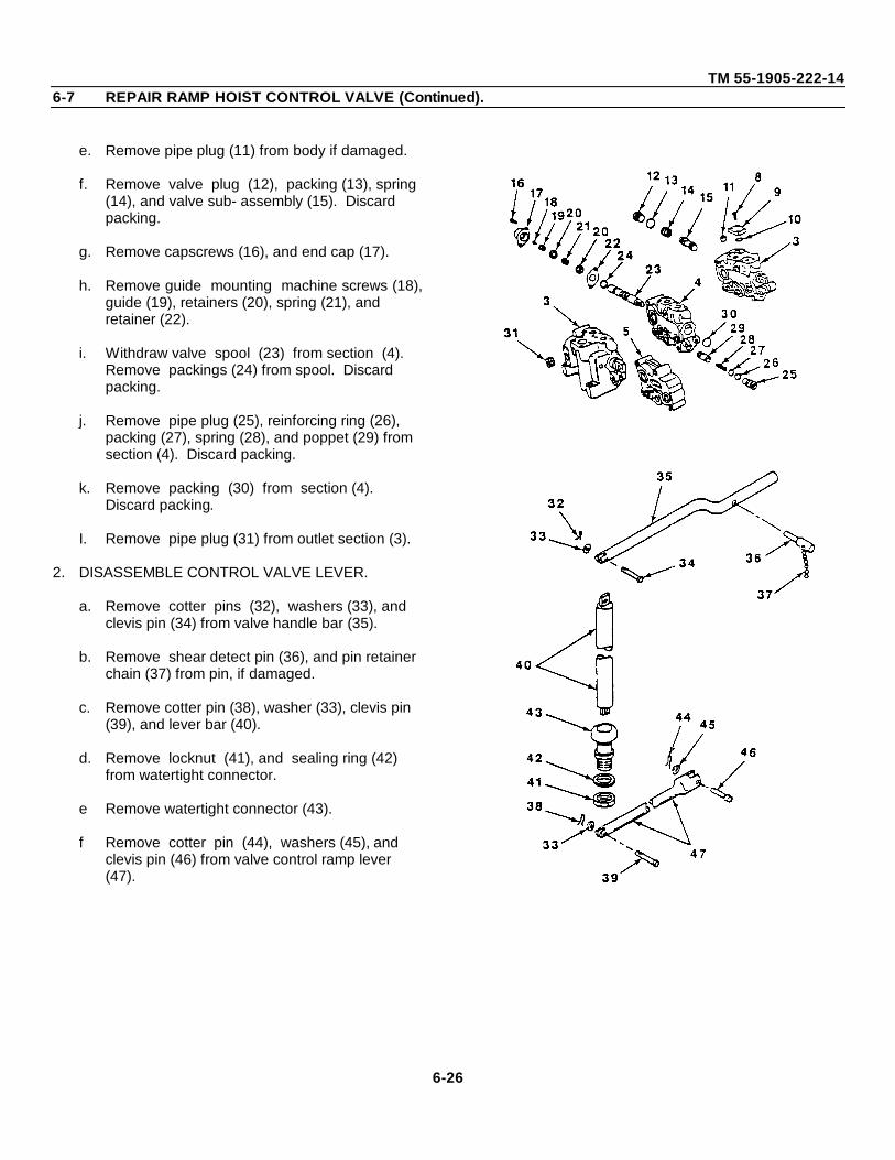
TM 55-1905-222-146-7 REPAIR RAMP HOIST CONTROL VALVE (Continued).
e. Remove pipe plug (11) from body if damaged.
f. Remove valve plug (12), packing (13), spring (14), and valve sub- assembly (15). Discard packing.
g. Remove capscrews (16), and end cap (17).
h. Remove guide mounting machine screws (18),guide (19), retainers (20), spring (21), and retainer (22).
i. Withdraw valve spool (23) from section (4). Remove packings (24) from spool. Discard packing.
j. Remove pipe plug (25), reinforcing ring (26), packing (27), spring (28), and poppet (29) from section (4). Discard packing.
k. Remove packing (30) from section (4). Discard packing.
I. Remove pipe plug (31) from outlet section (3).
2. DISASSEMBLE CONTROL VALVE LEVER.
a. Remove cotter pins (32), washers (33), and clevis pin (34) from valve handle bar (35).
b. Remove shear detect pin (36), and pin retainer chain (37) from pin, if damaged.
c. Remove cotter pin (38), washer (33), clevis pin (39), and lever bar (40).
d. Remove locknut (41), and sealing ring (42) from watertight connector.
e Remove watertight connector (43).
f Remove cotter pin (44), washers (45), and clevis pin (46) from valve control ramp lever (47).
6-26
TM 55-1905-222-146-7 REPAIR RAMP HOIST CONTROL VALVE (Continued).
CLEANING
INSPECT RAMP HOIST CONTROLVALVE
WARNING
Dry cleaning solvent, P-D-680, used to clean parts, is potentially dangerous to personneland property. Avoid repeated or prolonged skin contact. Do not use near open flame orexcessive heat. Flash point of solvent is 1000 138°F (38°- 59°C).
a. Clean control valve parts. In mineral oil solvent,and place on a clean surface.
b. Clean control lever parts In cleaning solvent Federal Specification P-D- 680, and dry thoroughly.
INSPECTION
INSPECT CONTROL VALVE PARTS
a. Inspect springs for loss of tension or distortion.
b. Inspect spool for nicks, burrs, or scores.
c. Inspect threaded parts for thread damage.
d. Inspect end caps and plates for burrs, nicks, or other damage.
e. Inspect sealing surfacesof valve bodies,and sections for scores, burrs, or warpage.
f Inspect poppets for burrs or nicks.
g Replace packings.
h Replace all defective threaded parts.
6-27
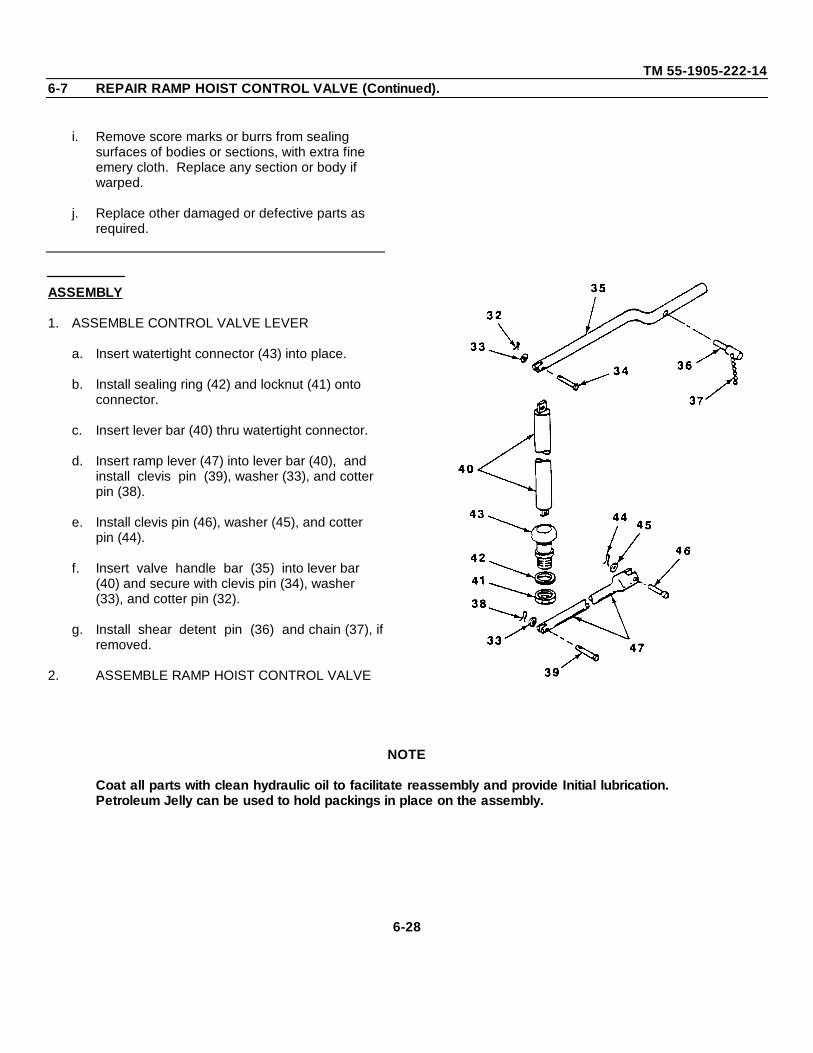
TM 55-1905-222-146-7 REPAIR RAMP HOIST CONTROL VALVE (Continued).
i. Remove score marks or burrs from sealing surfaces of bodies or sections, with extra fine emery cloth. Replace any section or body if warped.
j. Replace other damaged or defective parts as required.
ASSEMBLY
1. ASSEMBLE CONTROL VALVE LEVER
a. Insert watertight connector (43) into place.
b. Install sealing ring (42) and locknut (41) onto connector.
c. Insert lever bar (40) thru watertight connector.
d. Insert ramp lever (47) into lever bar (40), and install clevis pin (39), washer (33), and cotter pin (38).
e. Install clevis pin (46), washer (45), and cotter pin (44).
f. Insert valve handle bar (35) into lever bar (40) and secure with clevis pin (34), washer (33), and cotter pin (32).
g. Install shear detent pin (36) and chain (37), ifremoved.
2. ASSEMBLE RAMP HOIST CONTROL VALVE
NOTE
Coat all parts with clean hydraulic oil to facilitate reassembly and provide Initial lubrication.Petroleum Jelly can be used to hold packings in place on the assembly.
6-28

TM 55-1905-222-146-7 REPAIR RAMP HOIST CONTROL VALVE (Continued).
a. Install plug (31) in outlet body (3) DO NOT overtighten plug.
b Install packing (30) In section (4).
c Insert spring (28) into poppet (29). Then insert poppet into body section (4).
d. Install packing (27) and reinforcing ring (26), and secure with pipe plug (25). Tighten plug securely. DO NOT OVERTIGHTEN PLUG.
e. Place packings(24) in position on valve spool (23) Then, insert spool (23) into body section.
f. Install retainer (22), retainer (20), spring (21), retainer (20), valve guide (19), and secure with guide mounting screw (18). Align flat retainer (22) by shifting spool. Spool bind is an indication of retainer misalignment.
g. Install end cap (17), and secure with capscrews(16). Tighten end cap screws securely.
h. Install valve sub-assembly (15), spring (14), packing (13), and secure with plug (12).
i. Install pipe plug (11).
j. Install plate packing (10), plate (9), and secure with screws (8).
k. Install packings (6 and 7). in sections . Use petroleum jelly to hold packing in place in sections.
CAUTION
Make sure all mating surfaces of valve bodies are free of burrs and paint.
6-29
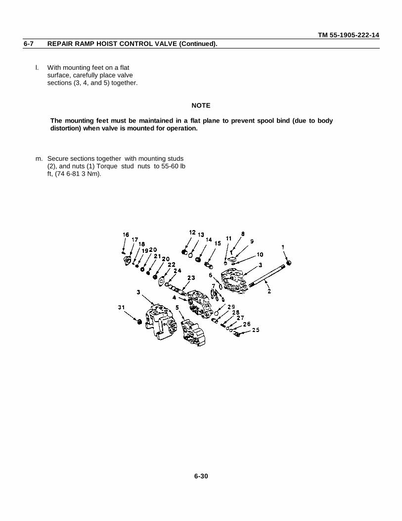
TM 55-1905-222-146-7 REPAIR RAMP HOIST CONTROL VALVE (Continued).
l. With mounting feet on a flatsurface, carefully place valvesections (3, 4, and 5) together.
NOTE
The mounting feet must be maintained in a flat plane to prevent spool bind (due to bodydistortion) when valve is mounted for operation.
m. Secure sections together with mounting studs (2), and nuts (1) Torque stud nuts to 55-60 lb ft, (74 6-81 3 Nm).
6-30
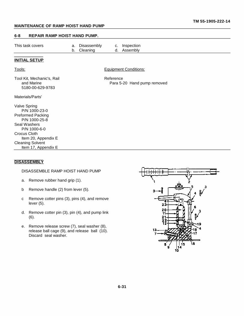
TM 55-1905-222-14MAINTENANCE OF RAMP HOIST HAND PUMP
6-8 REPAIR RAMP HOIST HAND PUMP.
This task covers a. Disassembly c. Inspectionb. Cleaning d. Assembly
INITIAL SETUP
Tools: Equipment Conditions:
Tool Kit, Mechanic's, Rail Referenceand Marine Para 5-20 Hand pump removed5180-00-629-9783
Materials/Parts'
Valve SpringP/N 1000-23-0
Preformed PackingP/N 1000-25-8
Seal WashersP/N 1000-6-0
Crocus ClothItem 20, Appendix E
Cleaning SolventItem 17, Appendix E
DISASSEMBLY
DISASSEMBLE RAMP HOIST HAND PUMP
a. Remove rubber hand grip (1).
b Remove handle (2) from lever (5).
c Remove cotter pins (3), pins (4), and remove lever (5).
d. Remove cotter pin (3), pin (4), and pump link (6).
e. Remove release screw (7), seal washer (8), release ball cage (9), and release ball (10). Discard seal washer.
6-31
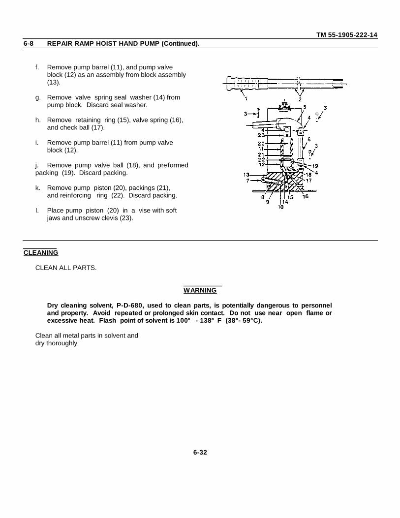
TM 55-1905-222-146-8 REPAIR RAMP HOIST HAND PUMP (Continued).
f. Remove pump barrel (11), and pump valve block (12) as an assembly from block assembly (13).
g. Remove valve spring seal washer (14) from pump block. Discard seal washer.
h. Remove retaining ring (15), valve spring (16), and check ball (17).
i. Remove pump barrel (11) from pump valve block (12).
j. Remove pump valve ball (18), and preformedpacking (19). Discard packing.
k. Remove pump piston (20), packings (21),and reinforcing ring (22). Discard packing.
I. Place pump piston (20) in a vise with soft jaws and unscrew clevis (23).
CLEANING
CLEAN ALL PARTS.
WARNING
Dry cleaning solvent, P-D-680, used to clean parts, is potentially dangerous to personneland property. Avoid repeated or prolonged skin contact. Do not use near open flame orexcessive heat. Flash point of solvent is 100° - 138°F (38°- 59°C).
Clean all metal parts in solvent anddry thoroughly
6-32
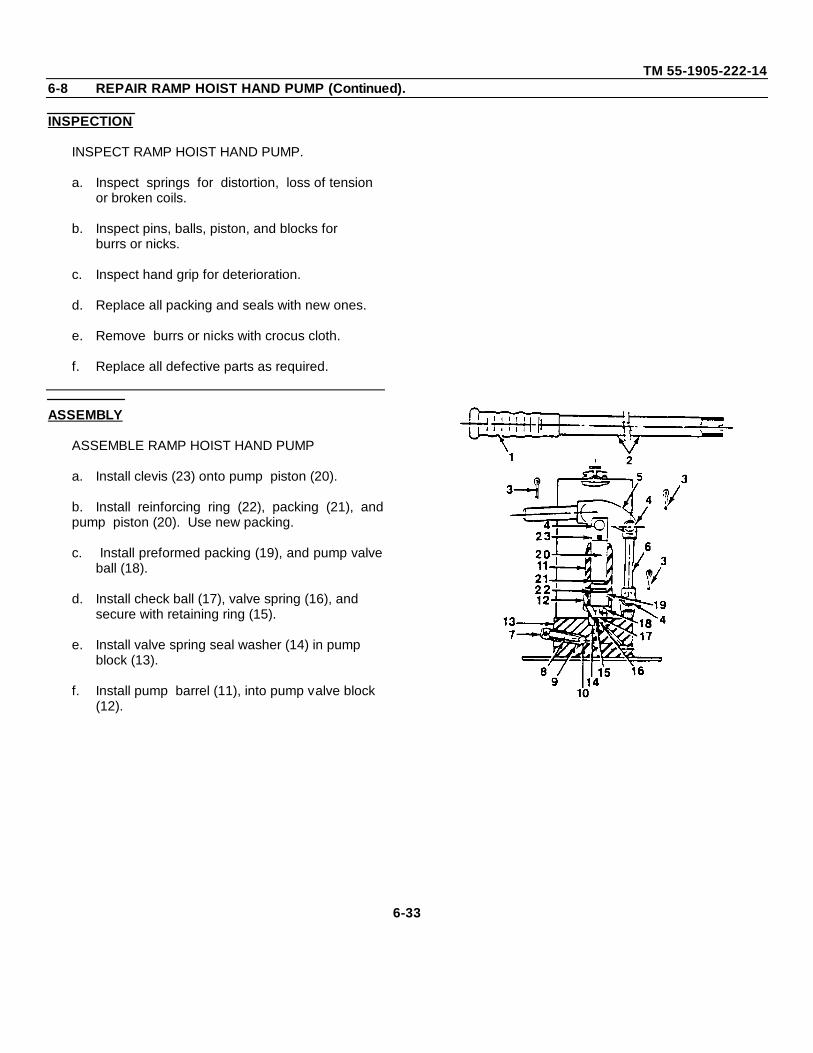
TM 55-1905-222-146-8 REPAIR RAMP HOIST HAND PUMP (Continued).
INSPECTION
INSPECT RAMP HOIST HAND PUMP.
a. Inspect springs for distortion, loss of tension or broken coils.
b. Inspect pins, balls, piston, and blocks for burrs or nicks.
c. Inspect hand grip for deterioration.
d. Replace all packing and seals with new ones.
e. Remove burrs or nicks with crocus cloth.
f. Replace all defective parts as required.
ASSEMBLY
ASSEMBLE RAMP HOIST HAND PUMP
a. Install clevis (23) onto pump piston (20).
b. Install reinforcing ring (22), packing (21), andpump piston (20). Use new packing.
c. Install preformed packing (19), and pump valveball (18).
d. Install check ball (17), valve spring (16), and secure with retaining ring (15).
e. Install valve spring seal washer (14) in pump block (13).
f. Install pump barrel (11), into pump valve block (12).
6-33
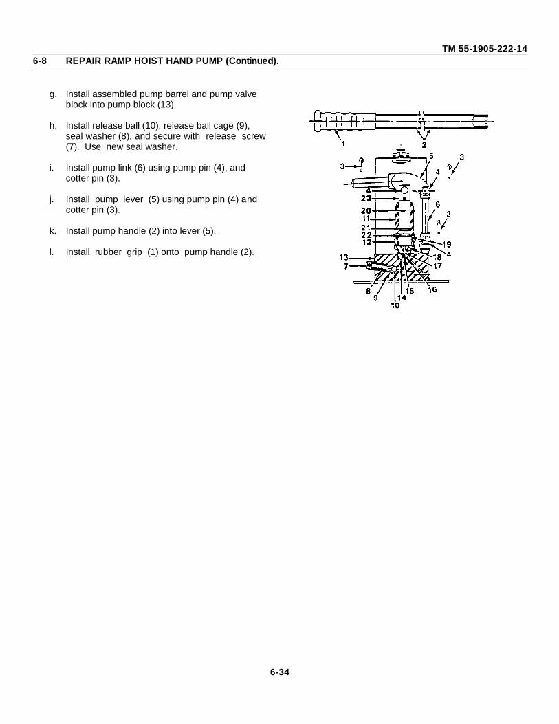
TM 55-1905-222-146-8 REPAIR RAMP HOIST HAND PUMP (Continued).
g. Install assembled pump barrel and pump valve block into pump block (13).
h. Install release ball (10), release ball cage (9), seal washer (8), and secure with release screw(7). Use new seal washer.
i. Install pump link (6) using pump pin (4), and cotter pin (3).
j. Install pump lever (5) using pump pin (4) and cotter pin (3).
k. Install pump handle (2) into lever (5).
l. Install rubber grip (1) onto pump handle (2).
6-34
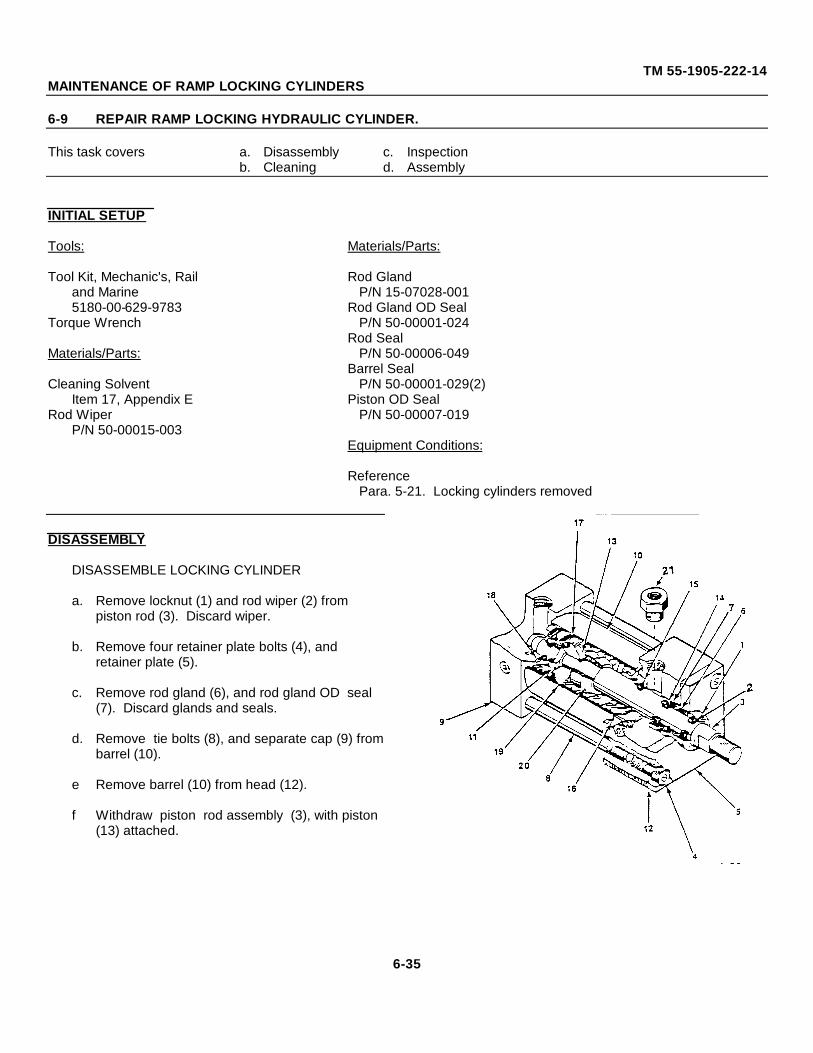
TM 55-1905-222-14MAINTENANCE OF RAMP LOCKING CYLINDERS
6-9 REPAIR RAMP LOCKING HYDRAULIC CYLINDER.
This task covers a. Disassembly c. Inspectionb. Cleaning d. Assembly
INITIAL SETUP
Tools: Materials/Parts:
Tool Kit, Mechanic's, Rail Rod Glandand Marine P/N 15-07028-0015180-00-629-9783 Rod Gland OD Seal
Torque Wrench P/N 50-00001-024Rod Seal
Materials/Parts: P/N 50-00006-049Barrel Seal
Cleaning Solvent P/N 50-00001-029(2)Item 17, Appendix E Piston OD Seal
Rod Wiper P/N 50-00007-019P/N 50-00015-003
Equipment Conditions:
ReferencePara. 5-21. Locking cylinders removed
DISASSEMBLY
DISASSEMBLE LOCKING CYLINDER
a. Remove locknut (1) and rod wiper (2) frompiston rod (3). Discard wiper.
b. Remove four retainer plate bolts (4), and retainer plate (5).
c. Remove rod gland (6), and rod gland OD seal (7). Discard glands and seals.
d. Remove tie bolts (8), and separate cap (9) frombarrel (10).
e Remove barrel (10) from head (12).
f Withdraw piston rod assembly (3), with piston (13) attached.
6-35
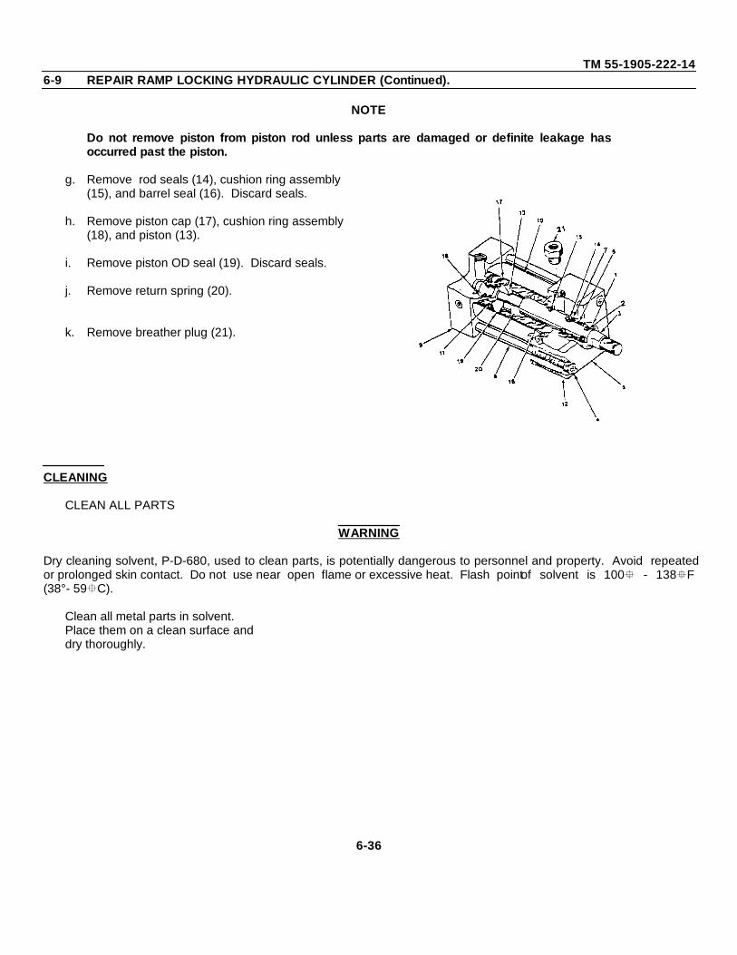
TM 55-1905-222-146-9 REPAIR RAMP LOCKING HYDRAULIC CYLINDER (Continued).
NOTE
Do not remove piston from piston rod unless parts are damaged or definite leakage hasoccurred past the piston.
g. Remove rod seals (14), cushion ring assembly (15), and barrel seal (16). Discard seals.
h. Remove piston cap (17), cushion ring assembly (18), and piston (13).
i. Remove piston OD seal (19). Discard seals.
j. Remove return spring (20).
k. Remove breather plug (21).
CLEANING
CLEAN ALL PARTS
WARNING
Dry cleaning solvent, P-D-680, used to clean parts, is potentially dangerous to personnel and property. Avoid repeatedor prolonged skin contact. Do not use near open flame or excessive heat. Flash pointof solvent is 100 - 138F(38°- 59C).
Clean all metal parts in solvent.Place them on a clean surface anddry thoroughly.
6-36
TM 55-1905-222-146-9 REPAIR RAMP LOCKING HYDRAULIC CYLINDER (Continued).
INSPECTION
INSPECT LOCKING CYLINDER
a. Inspect cylinder, piston rod, and piston for burrs and scores.
b. Inspect threaded parts for thread damage.
c. Inspect retainer plate, head and cap for cracks or breaks.
d. Inspect spring for loss of tension or distortion.
e. Remove burrs by light stoning or lapping.
f. Remove scoring from piston rod, cylinder and piston by light stoning or lapping.
g. Replace all seals and glands.
h. Replace other defective parts. Asnecessary.
ASSEMBLY
ASSEMBLE LOCKING CYLINDER.
NOTE
Lubricate parts with clean hydraulic fluid before assembly.
a. Install breather plug (21).
b. Install return spring (20).
6-37
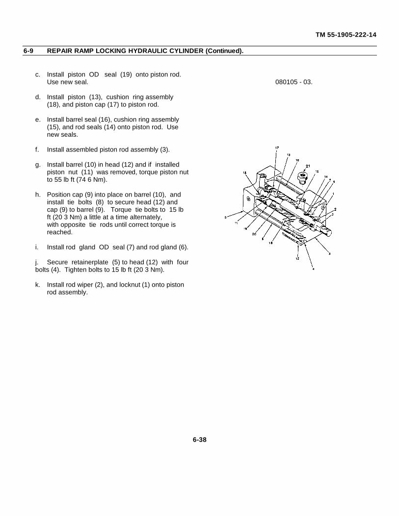
TM 55-1905-222-14
6-9 REPAIR RAMP LOCKING HYDRAULIC CYLINDER (Continued).
c. Install piston OD seal (19) onto piston rod. Use new seal.
d. Install piston (13), cushion ring assembly (18), and piston cap (17) to piston rod.
e. Install barrel seal (16), cushion ring assembly (15), and rod seals (14) onto piston rod. Use new seals.
f. Install assembled piston rod assembly (3).
g. Install barrel (10) in head (12) and if installed piston nut (11) was removed, torque piston nutto 55 lb ft (74 6 Nm).
h. Position cap (9) into place on barrel (10), and install tie bolts (8) to secure head (12) and cap (9) to barrel (9). Torque tie bolts to 15 lb ft (20 3 Nm) a little at a time alternately, with opposite tie rods until correct torque is reached.
i. Install rod gland OD seal (7) and rod gland (6).
j. Secure retainerplate (5) to head (12) with fourbolts (4). Tighten bolts to 15 lb ft (20 3 Nm).
k. Install rod wiper (2), and locknut (1) onto piston rod assembly.
080105 - 03.
6-38
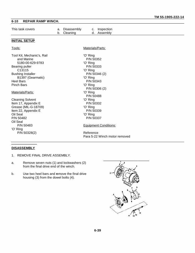
TM 55-1905-222-146-10 REPAIR RAMP WINCH.
This task covers a. Disassembly c. Inspectionb. Cleaning d. Assembly
INITIAL SETUP
Tools: Materials/Parts:
Tool Kit, Mechanic's, Rail 'O' Ringand Marine P/N 503525180-00-629-9783 'O' Ring
Bearing puller P/N 50333C13115 'O' Ring
Bushing Installer P/N 50346 (2)B1397 (Gearmatic) 'O' Ring
Heel Bars P/N 50343Pinch Bars 'O' Ring
P/N 50306 (2)Materials/Parts: 'O' Ring
P/N 50488Cleaning Solvent 'O' RingItem 17, Appendix E P/N 50332Grease (MIL-G-18709) 'O' RingItem 22, Appendix E P/N 50339Oil Seal 'O' RingP/N 50482 P/N 50337Oil Seal
P/N 50483 Equipment Conditions:'O' Ring
P/N 50328(2) ReferencePara 5-22 Winch motor removed
DISASSEMBLY
1. REMOVE FINAL DRIVE ASSEMBLY.
a. Remove seven nuts (1) and lockwashers (2) from the final drive end of the winch.
b. Use two heel bars and remove the final drive housing (3) from the dowel bolts (4).
6-39
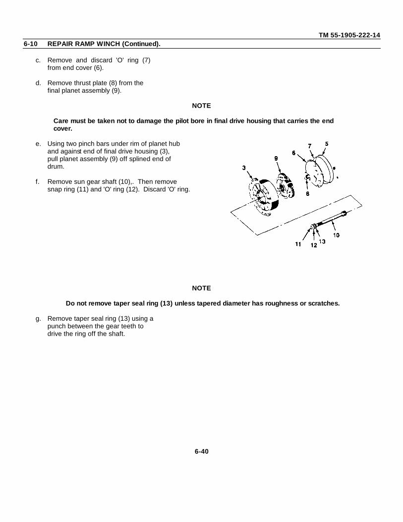
TM 55-1905-222-146-10 REPAIR RAMP WINCH (Continued).
c. Remove and discard 'O' ring (7)from end cover (6).
d. Remove thrust plate (8) from thefinal planet assembly (9).
NOTE
Care must be taken not to damage the pilot bore in final drive housing that carries the endcover.
e. Using two pinch bars under rim of planet hub and against end of final drive housing (3), pull planet assembly (9) off splined end of drum.
f. Remove sun gear shaft (10),. Then remove snap ring (11) and 'O' ring (12). Discard 'O' ring.
NOTE
Do not remove taper seal ring (13) unless tapered diameter has roughness or scratches.
g. Remove taper seal ring (13) using apunch between the gear teeth todrive the ring off the shaft.
6-40
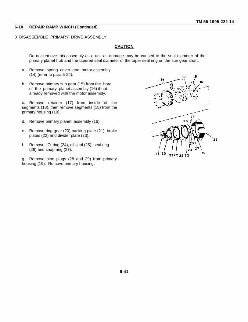
TM 55-1905-222-146-10 REPAIR RAMP WINCH (Continued).
3 DISASSEMBLE PRIMARY DRIVE ASSEMBLY
CAUTION
Do not remove this assembly as a unit as damage may be caused to the seal diameter of theprimary planet hub and the tapered seal diameter of the taper seal ring on the sun gear shaft.
a. Remove spring cover and motor assembly (14) (refer to para 5-24).
b. Remove primary sun gear (15) from the bore of the primary planet assembly (16) if not already removed with the motor assembly.
c. Remove retainer (17) from inside of thesegments (18), then remove segments (18) from theprimary housing (19).
d. Remove primary planet assembly (16).
e. Remove ring gear (20) backing plate (21), brakeplates (22) and divider plate (23).
f. Remove 'O' ring (24), oil seal (25), seal ring (26) and snap ring (27).
g. Remove pipe plugs (28 and 29) from primaryhousing (19). Remove primary housing.
6-41
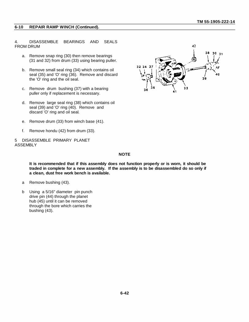
TM 55-1905-222-146-10 REPAIR RAMP WINCH (Continued).
4. DISASSEMBLE BEARINGS AND SEALSFROM DRUM
a. Remove snap ring (30) then remove bearings (31 and 32) from drum (33) using bearing puller.
b. Remove small seal ring (34) which contains oil seal (35) and 'O' ring (36). Remove and discardthe 'O' ring and the oil seal.
c. Remove drum bushing (37) with a bearing puller only if replacement is necessary.
d. Remove large seal ring (38) which contains oil seal (39) and 'O' ring (40). Remove and discard 'O' ring and oil seal.
e. Remove drum (33) from winch base (41).
f. Remove hondu (42) from drum (33).
5 DISASSEMBLE PRIMARY PLANETASSEMBLY
NOTE
It is recommended that if this assembly does not function properly or is worn, it should betraded in complete for a new assembly. If the assembly is to be disassembled do so only ifa clean, dust free work bench is available.
a Remove bushing (43).
b Using a 5/16" diameter pin punchdrive pin (44) through the planethub (45) until it can be removedthrough the bore which carries thebushing (43).
6-42
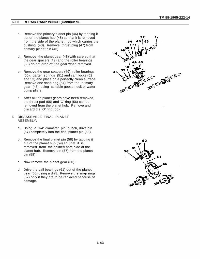
TM 55-1905-222-146-10 REPAIR RAMP WINCH (Continued).
c. Remove the primary planet pin (46) by tapping itout of the planet hub (45) so that it is removed from the side of the planet hub which carries thebushing (43). Remove thrust plug (47) from primary planet pin (46).
d. Remove the planet gear (48) with care so that the gear spacers (49) and the roller bearings (50) do not drop off the gear when removed.
e. Remove the gear spacers (49), roller bearings (50), garter springs (51) and cam locks (52 and 53) and place on a perfectly clean surface. Remove one snap ring (54) from the primary gear (48) using suitable goose neck or water pump pliers.
f. After all the planet gears have been removed, the thrust pad (55) and 'O' ring (56) can be removed from the planet hub. Remove and discard the 'O' ring (56).
6 DISASSEMBLE FINAL PLANETASSEMBLY.
a. Using a 1/4" diameter pin punch, drive pin (57) completely into the final planet pin (58).
b. Remove the final planet pin (58) by tapping it out of the planet hub (59) so that it is removed from the splined bore side of the planet hub. Remove pin (57) from the planet pin (58).
c Now remove the planet gear (60).
d Drive the ball bearings (61) out of the planet gear (60) using a drift. Remove the snap rings (62) only if they are to be replaced because of damage.
6-43
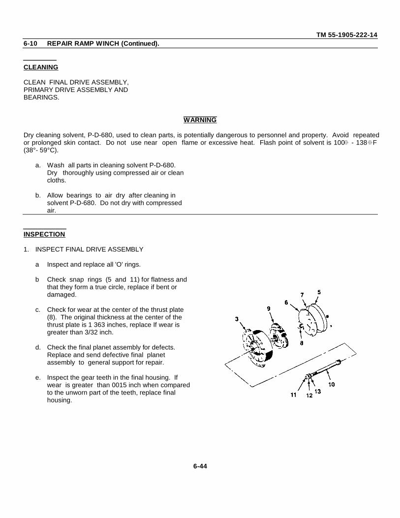
TM 55-1905-222-146-10 REPAIR RAMP WINCH (Continued).
CLEANING
CLEAN FINAL DRIVE ASSEMBLY,PRIMARY DRIVE ASSEMBLY ANDBEARINGS.
WARNING
Dry cleaning solvent, P-D-680, used to clean parts, is potentially dangerous to personnel and property. Avoid repeatedor prolonged skin contact. Do not use near open flame or excessive heat. Flash point of solvent is 100 - 138F(38°- 59°C).
a. Wash all parts in cleaning solvent P-D-680. Dry thoroughly using compressed air or clean cloths.
b. Allow bearings to air dry after cleaning in solvent P-D-680. Do not dry with compressed air.
INSPECTION
1. INSPECT FINAL DRIVE ASSEMBLY
a Inspect and replace all 'O' rings.
b Check snap rings (5 and 11) for flatness and that they form a true circle, replace if bent or damaged.
c. Check for wear at the center of the thrust plate (8). The original thickness at the center of the thrust plate is 1 363 inches, replace If wear is greater than 3/32 inch.
d. Check the final planet assembly for defects. Replace and send defective final planet assembly to general support for repair.
e. Inspect the gear teeth in the final housing. If wear is greater than 0015 inch when comparedto the unworn part of the teeth, replace final housing.
6-44
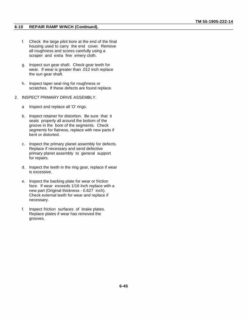
TM 55-1905-222-146-10 REPAIR RAMP WINCH (Continued).
f. Check the large pilot bore at the end of the finalhousing used to carry the end cover. Removeall roughness and scores carefully using a scraper and extra fine emery cloth.
g. Inspect sun gear shaft. Check gear teeth for wear. If wear is greater than .012 inch replace the sun gear shaft.
h. Inspect taper seal ring for roughness or scratches. If these defects are found replace.
2. INSPECT PRIMARY DRIVE ASSEMBLY.
a Inspect and replace all 'O' rings.
b. Inspect retainer for distortion. Be sure that it seats properly all around the bottom of the groove in the bore of the segments. Check segments for flatness, replace with new parts if bent or distorted.
c. Inspect the primary planet assembly for defects.Replace if necessary and send defective primary planet assembly to general support for repairs.
d. Inspect the teeth in the ring gear, replace if wearis excessive.
e. Inspect the backing plate for wear or friction face. If wear exceeds 1/16 Inch replace with a new part (Original thickness - 0.627 inch). Check external teeth for wear and replace if necessary.
f. Inspect friction surfaces of brake plates. Replace plates if wear has removed the grooves.
6-45
TM 55-1905-222-146-10 REPAIR RAMP WINCH (Continued).
g. Check divider plate for wear. If wear is excessive or if the plate is buckled or does not form a true circle, replace with a new part.
3. INSPECT DRUM AND BEARINGS.
a. Inspect and replace all 'O' rings and oil seals.
b. Check seal diameters at each end of drum for roughness. Clean and polish the seal diameters, using extra fine emery cloth. Check the bearing hub diameters for scores and wear. Replace drum If necessary.
c. Inspect 'O' ring seal face in bore of drum at thesplined end. Polish face with extra fine emery cloth if roughness and scratches are found. Replace drum If damage is excessive.
d. Inspect drum bushing for bruises, scores and wear. Use a scraper to remove all high spots. The original inside diameter of bushing is 2.190 inch. If wear is greater than 0.010 inch, replace bushing.
e. Inspect all ball bearings for wear and pitting at the balls and ball grooves. Replace bearings if worn or pitted.
6-46
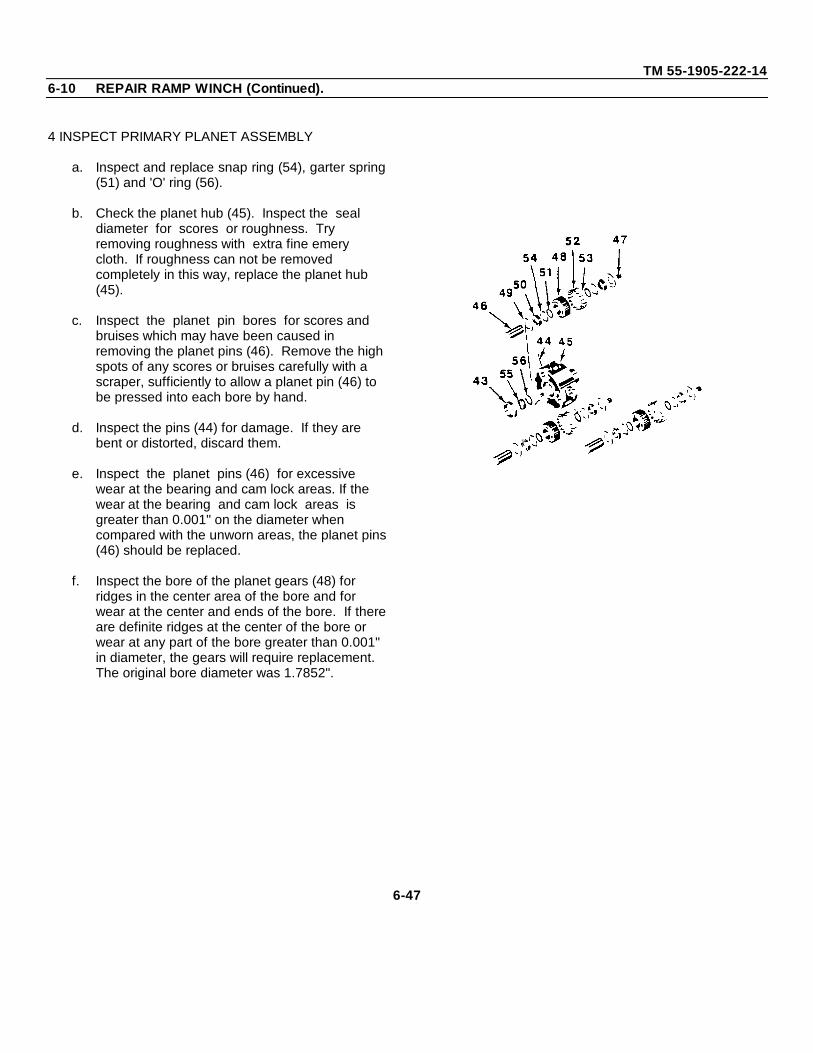
TM 55-1905-222-146-10 REPAIR RAMP WINCH (Continued).
4 INSPECT PRIMARY PLANET ASSEMBLY
a. Inspect and replace snap ring (54), garter spring(51) and 'O' ring (56).
b. Check the planet hub (45). Inspect the seal diameter for scores or roughness. Try removing roughness with extra fine emery cloth. If roughness can not be removed completely in this way, replace the planet hub (45).
c. Inspect the planet pin bores for scores and bruises which may have been caused in removing the planet pins (46). Remove the highspots of any scores or bruises carefully with a scraper, sufficiently to allow a planet pin (46) to be pressed into each bore by hand.
d. Inspect the pins (44) for damage. If they are bent or distorted, discard them.
e. Inspect the planet pins (46) for excessive wear at the bearing and cam lock areas. If the wear at the bearing and cam lock areas is greater than 0.001" on the diameter when compared with the unworn areas, the planet pins(46) should be replaced.
f. Inspect the bore of the planet gears (48) for ridges in the center area of the bore and for wear at the center and ends of the bore. If thereare definite ridges at the center of the bore or wear at any part of the bore greater than 0.001" in diameter, the gears will require replacement. The original bore diameter was 1.7852".
6-47
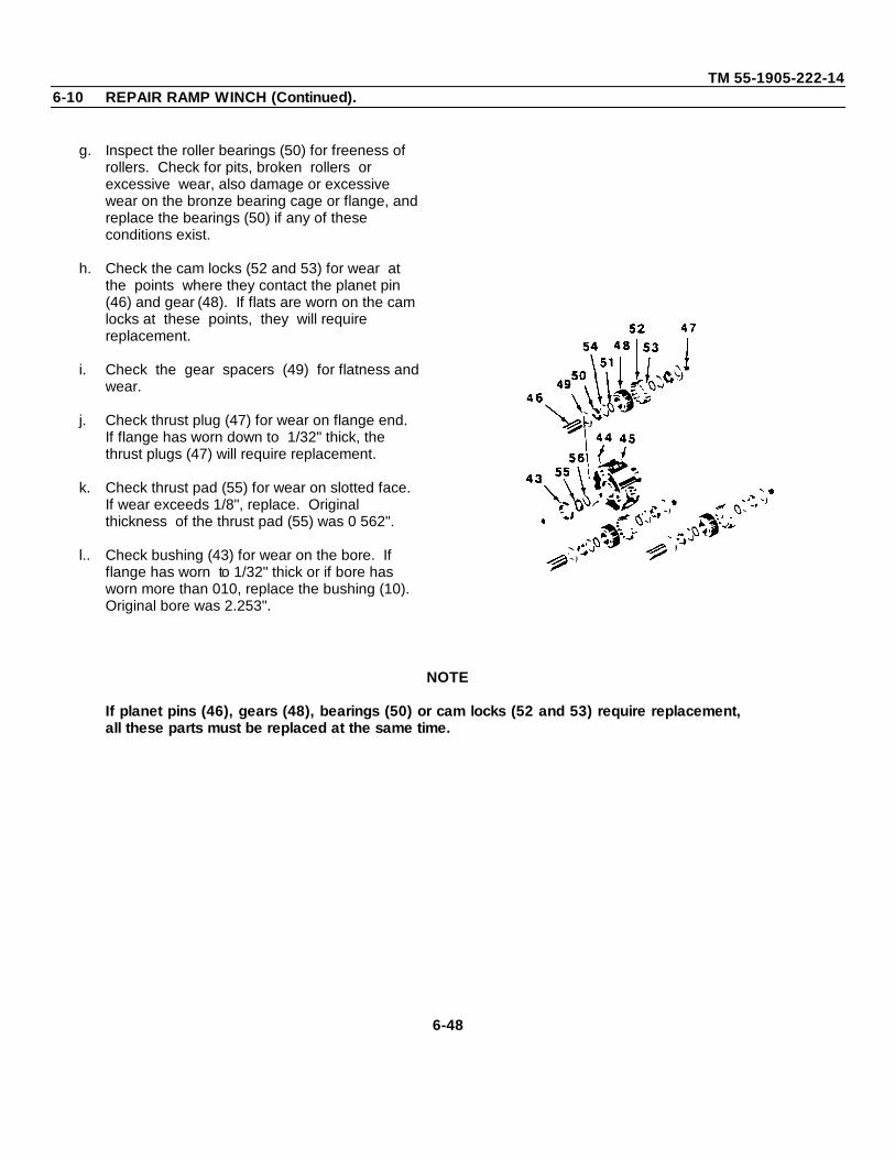
TM 55-1905-222-146-10 REPAIR RAMP WINCH (Continued).
g. Inspect the roller bearings (50) for freeness of rollers. Check for pits, broken rollers or excessive wear, also damage or excessive wear on the bronze bearing cage or flange, and replace the bearings (50) if any of these conditions exist.
h. Check the cam locks (52 and 53) for wear at the points where they contact the planet pin (46) and gear (48). If flats are worn on the cam locks at these points, they will require replacement.
i. Check the gear spacers (49) for flatness and wear.
j. Check thrust plug (47) for wear on flange end. If flange has worn down to 1/32" thick, the thrust plugs (47) will require replacement.
k. Check thrust pad (55) for wear on slotted face. If wear exceeds 1/8", replace. Original thickness of the thrust pad (55) was 0 562".
l.. Check bushing (43) for wear on the bore. If flange has worn to 1/32" thick or if bore has worn more than 010, replace the bushing (10). Original bore was 2.253".
NOTE
If planet pins (46), gears (48), bearings (50) or cam locks (52 and 53) require replacement,all these parts must be replaced at the same time.
6-48
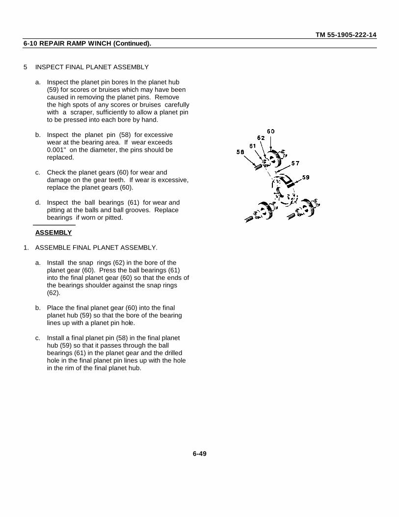
TM 55-1905-222-146-10 REPAIR RAMP WINCH (Continued).
5 INSPECT FINAL PLANET ASSEMBLY
a. Inspect the planet pin bores In the planet hub (59) for scores or bruises which may have been caused in removing the planet pins. Remove the high spots of any scores or bruises carefullywith a scraper, sufficiently to allow a planet pinto be pressed into each bore by hand.
b. Inspect the planet pin (58) for excessive wear at the bearing area. If wear exceeds 0.001" on the diameter, the pins should be replaced.
c. Check the planet gears (60) for wear and damage on the gear teeth. If wear is excessive,replace the planet gears (60).
d. Inspect the ball bearings (61) for wear and pitting at the balls and ball grooves. Replace bearings if worn or pitted.
ASSEMBLY
1. ASSEMBLE FINAL PLANET ASSEMBLY.
a. Install the snap rings (62) in the bore of the planet gear (60). Press the ball bearings (61) into the final planet gear (60) so that the ends ofthe bearings shoulder against the snap rings (62).
b. Place the final planet gear (60) into the final planet hub (59) so that the bore of the bearing lines up with a planet pin hole.
c. Install a final planet pin (58) in the final planet hub (59) so that it passes through the ball bearings (61) in the planet gear and the drilled hole in the final planet pin lines up with the hole in the rim of the final planet hub.
6-49
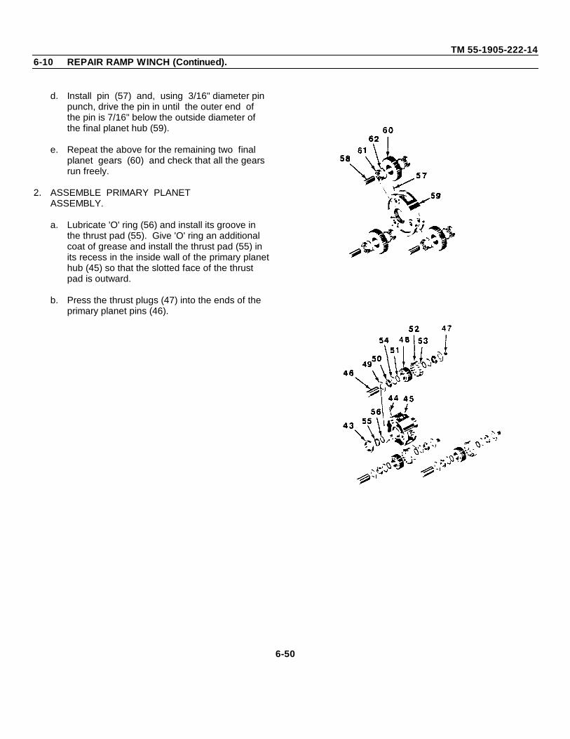
TM 55-1905-222-146-10 REPAIR RAMP WINCH (Continued).
d. Install pin (57) and, using 3/16" diameter pin punch, drive the pin in until the outer end of the pin is 7/16" below the outside diameter of the final planet hub (59).
e. Repeat the above for the remaining two final planet gears (60) and check that all the gears run freely.
2. ASSEMBLE PRIMARY PLANETASSEMBLY.
a. Lubricate 'O' ring (56) and install its groove in the thrust pad (55). Give 'O' ring an additional coat of grease and install the thrust pad (55) in its recess in the inside wall of the primary planethub (45) so that the slotted face of the thrust pad is outward.
b. Press the thrust plugs (47) into the ends of the primary planet pins (46).
6-50
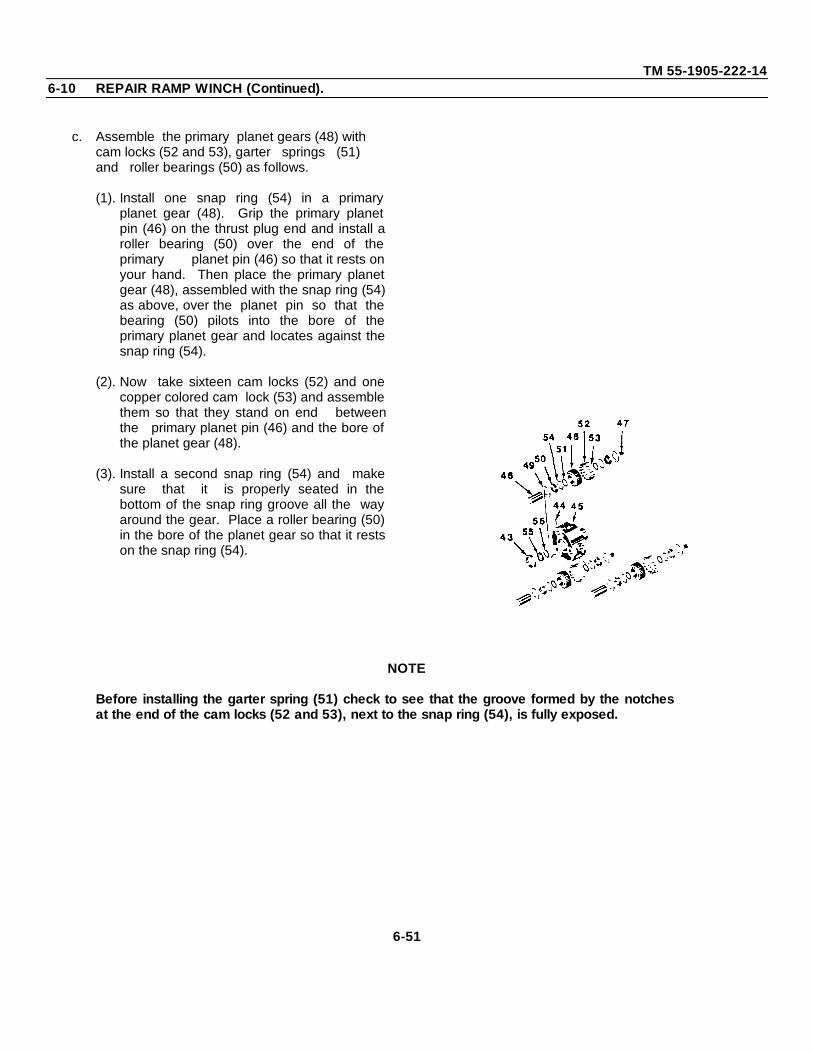
TM 55-1905-222-146-10 REPAIR RAMP WINCH (Continued).
c. Assemble the primary planet gears (48) with cam locks (52 and 53), garter springs (51) and roller bearings (50) as follows.
(1). Install one snap ring (54) in a primaryplanet gear (48). Grip the primary planetpin (46) on the thrust plug end and install aroller bearing (50) over the end of theprimary planet pin (46) so that it rests onyour hand. Then place the primary planetgear (48), assembled with the snap ring (54)as above, over the planet pin so that thebearing (50) pilots into the bore of theprimary planet gear and locates against thesnap ring (54).
(2). Now take sixteen cam locks (52) and onecopper colored cam lock (53) and assemblethem so that they stand on end betweenthe primary planet pin (46) and the bore ofthe planet gear (48).
(3). Install a second snap ring (54) and makesure that it is properly seated in thebottom of the snap ring groove all the wayaround the gear. Place a roller bearing (50)in the bore of the planet gear so that it restson the snap ring (54).
NOTE
Before installing the garter spring (51) check to see that the groove formed by the notchesat the end of the cam locks (52 and 53), next to the snap ring (54), is fully exposed.
6-51
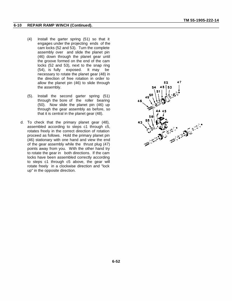
TM 55-1905-222-146-10 REPAIR RAMP WINCH (Continued).
(4) Install the garter spring (51) so that itengages under the projecting ends of thecam locks (52 and 53). Turn the completeassembly over and slide the planet pin(46) down through the planet gear untilthe groove formed on the end of the camlocks (52 and 53), next to the snap ring(54), is fully exposed. It may benecessary to rotate the planet gear (48) inthe direction of free rotation in order toallow the planet pin (46) to slide throughthe assembly.
(5). Install the second garter spring (51)through the bore of the roller bearing(50). Now slide the planet pin (46) upthrough the gear assembly as before, sothat it is central in the planet gear (48).
d. To check that the primary planet gear (48),assembled according to steps c1 through c5,rotates freely in the correct direction of rotationproceed as follows. Hold the primary planet pin(46) stationary with one hand and view the endof the gear assembly while the thrust plug (47)points away from you. With the other hand tryto rotate the gear in both directions. If the camlocks have been assembled correctly accordingto steps c1 through c5 above, the gear willrotate freely in a clockwise direction and "lockup" in the opposite direction.
6-52
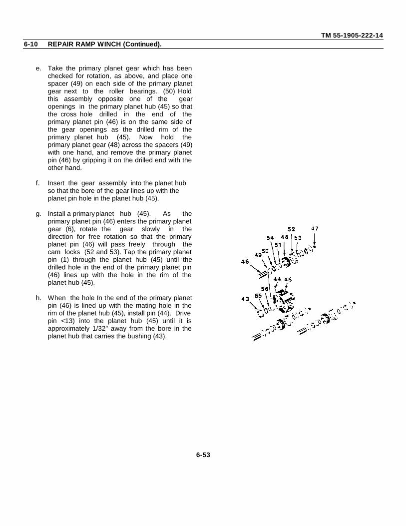
TM 55-1905-222-146-10 REPAIR RAMP WINCH (Continued).
e. Take the primary planet gear which has beenchecked for rotation, as above, and place onespacer (49) on each side of the primary planetgear next to the roller bearings. (50) Holdthis assembly opposite one of the gearopenings in the primary planet hub (45) so thatthe cross hole drilled in the end of theprimary planet pin (46) is on the same side ofthe gear openings as the drilled rim of theprimary planet hub (45). Now hold theprimary planet gear (48) across the spacers (49)with one hand, and remove the primary planetpin (46) by gripping it on the drilled end with theother hand.
f. Insert the gear assembly into the planet hub so that the bore of the gear lines up with the planet pin hole in the planet hub (45).
g. Install a primaryplanet hub (45). As theprimary planet pin (46) enters the primary planetgear (6), rotate the gear slowly in thedirection for free rotation so that the primaryplanet pin (46) will pass freely through thecam locks (52 and 53). Tap the primary planetpin (1) through the planet hub (45) until thedrilled hole in the end of the primary planet pin(46) lines up with the hole in the rim of theplanet hub (45).
h. When the hole In the end of the primary planetpin (46) is lined up with the mating hole in therim of the planet hub (45), install pin (44). Drivepin <13) into the planet hub (45) until it isapproximately 1/32" away from the bore in theplanet hub that carries the bushing (43).
6-53
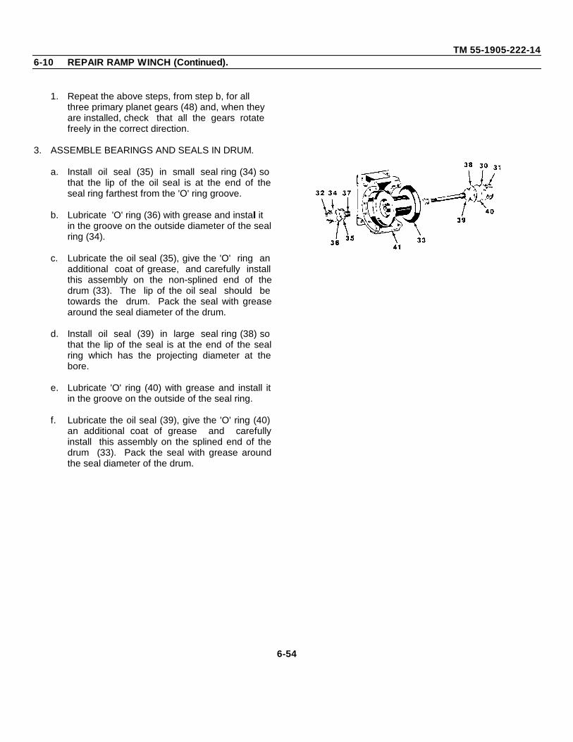
TM 55-1905-222-146-10 REPAIR RAMP WINCH (Continued).
1. Repeat the above steps, from step b, for all three primary planet gears (48) and, when they are installed, check that all the gears rotate freely in the correct direction.
3. ASSEMBLE BEARINGS AND SEALS IN DRUM.
a. Install oil seal (35) in small seal ring (34) sothat the lip of the oil seal is at the end of theseal ring farthest from the 'O' ring groove.
b. Lubricate 'O' ring (36) with grease and install it in the groove on the outside diameter of the sealring (34).
c. Lubricate the oil seal (35), give the 'O' ring anadditional coat of grease, and carefully installthis assembly on the non-splined end of thedrum (33). The lip of the oil seal should betowards the drum. Pack the seal with greasearound the seal diameter of the drum.
d. Install oil seal (39) in large seal ring (38) sothat the lip of the seal is at the end of the sealring which has the projecting diameter at thebore.
e. Lubricate 'O' ring (40) with grease and install itin the groove on the outside of the seal ring.
f. Lubricate the oil seal (39), give the 'O' ring (40)an additional coat of grease and carefullyinstall this assembly on the splined end of thedrum (33). Pack the seal with grease aroundthe seal diameter of the drum.
6-54
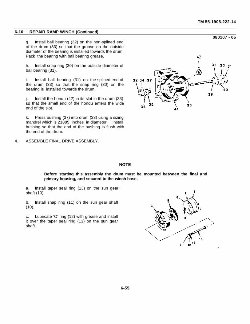
TM 55-1905-222-14
6-10 REPAIR RAMP WINCH (Continued).080107 - 05
g. Install ball bearing (32) on the non-splined endof the drum (33) so that the groove on the outsidediameter of the bearing is installed towards the drum.Pack the bearing with ball bearing grease.
h. Install snap ring (30) on the outside diameter ofball bearing (31).
i. Install ball bearing (31) on the splined end ofthe drum (33) so that the snap ring (30) on thebearing is installed towards the drum.
j. Install the hondu (42) in its slot in the drum (33)so that the small end of the hondu enters the wideend of the slot.
k. Press bushing (37) into drum (33) using a sizingmandrel which is 21885 inches in diameter. Installbushing so that the end of the bushing is flush withthe end of the drum.
4. ASSEMBLE FINAL DRIVE ASSEMBLY.
NOTE
Before starting this assembly the drum must be mounted between the final andprimary housing, and secured to the winch base.
a. Install taper seal ring (13) on the sun gearshaft (10).
b. Install snap ring (11) on the sun gear shaft(10).
c. Lubricate 'O' ring (12) with grease and installit over the taper seal ring (13) on the sun gearshaft.
`
6-55
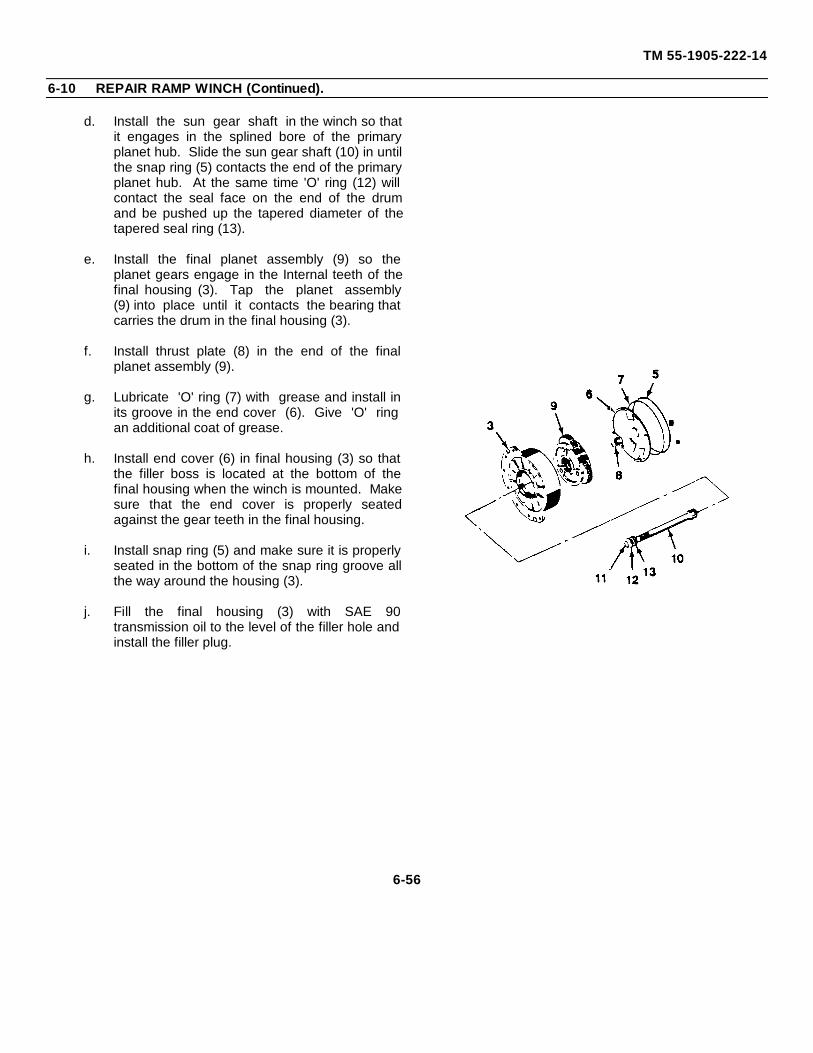
TM 55-1905-222-14
6-10 REPAIR RAMP WINCH (Continued).
d. Install the sun gear shaft in the winch so thatit engages in the splined bore of the primaryplanet hub. Slide the sun gear shaft (10) in untilthe snap ring (5) contacts the end of the primaryplanet hub. At the same time 'O' ring (12) willcontact the seal face on the end of the drumand be pushed up the tapered diameter of thetapered seal ring (13).
e. Install the final planet assembly (9) so theplanet gears engage in the Internal teeth of thefinal housing (3). Tap the planet assembly(9) into place until it contacts the bearing thatcarries the drum in the final housing (3).
f. Install thrust plate (8) in the end of the finalplanet assembly (9).
g. Lubricate 'O' ring (7) with grease and install inits groove in the end cover (6). Give 'O' ringan additional coat of grease.
h. Install end cover (6) in final housing (3) so thatthe filler boss is located at the bottom of thefinal housing when the winch is mounted. Makesure that the end cover is properly seatedagainst the gear teeth in the final housing.
i. Install snap ring (5) and make sure it is properlyseated in the bottom of the snap ring groove allthe way around the housing (3).
j. Fill the final housing (3) with SAE 90transmission oil to the level of the filler hole andinstall the filler plug.
6-56
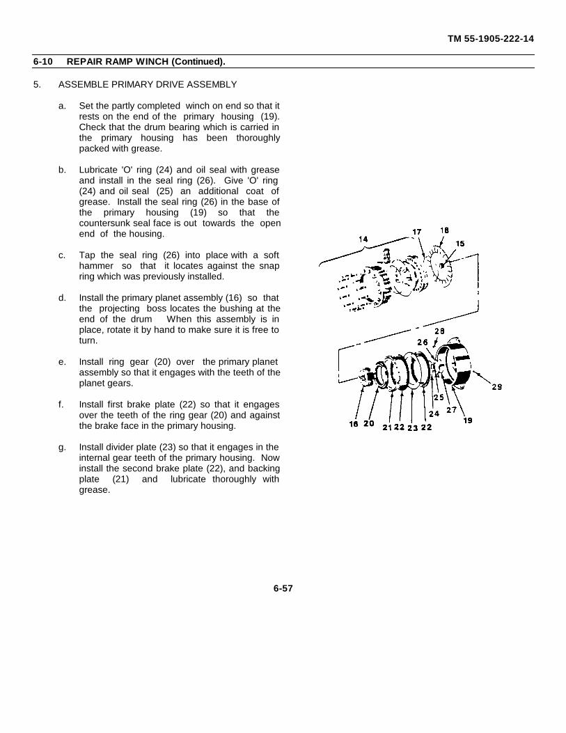
TM 55-1905-222-14
6-10 REPAIR RAMP WINCH (Continued).
5. ASSEMBLE PRIMARY DRIVE ASSEMBLY
a. Set the partly completed winch on end so that itrests on the end of the primary housing (19).Check that the drum bearing which is carried inthe primary housing has been thoroughlypacked with grease.
b. Lubricate 'O' ring (24) and oil seal with greaseand install in the seal ring (26). Give 'O' ring(24) and oil seal (25) an additional coat ofgrease. Install the seal ring (26) in the base ofthe primary housing (19) so that thecountersunk seal face is out towards the openend of the housing.
c. Tap the seal ring (26) into place with a softhammer so that it locates against the snapring which was previously installed.
d. Install the primary planet assembly (16) so thatthe projecting boss locates the bushing at theend of the drum When this assembly is inplace, rotate it by hand to make sure it is free toturn.
e. Install ring gear (20) over the primary planetassembly so that it engages with the teeth of theplanet gears.
f. Install first brake plate (22) so that it engagesover the teeth of the ring gear (20) and againstthe brake face in the primary housing.
g. Install divider plate (23) so that it engages in theinternal gear teeth of the primary housing. Nowinstall the second brake plate (22), and backingplate (21) and lubricate thoroughly withgrease.
6-57
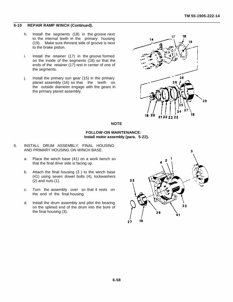
TM 55-1905-222-14
6-10 REPAIR RAMP WINCH (Continued).
h. Install the segments (18) in the groove nextto the internal teeth in the primary housing(19). Make sure thinnest side of groove is nextto the brake piston.
i. Install the retainer (17) in the groove formedon the inside of the segments (18) so that theends of the retainer (17) rest in center of one ofthe segments.
j. Install the primary sun gear (15) in the primaryplanet assembly (16) so that the teeth onthe outside diameter engage with the gears inthe primary planet assembly.
NOTE
FOLLOW-ON MAINTENANCE:Install motor assembly (para. 5-22).
6. INSTALL DRUM ASSEMBLY, FINAL HOUSINGAND PRIMARY HOUSING ON WINCH BASE.
a. Place the winch base (41) on a work bench sothat the final drive side is facing up.
b. Attach the final housing (3 ) to the winch base(41) using seven dowel bolts (4), lockwashers(2) and nuts (1).
c. Turn the assembly over so that it rests onthe end of the final housing.
d. Install the drum assembly and pilot the bearingon the splined end of the drum into the bore ofthe final housing (3).
6-58
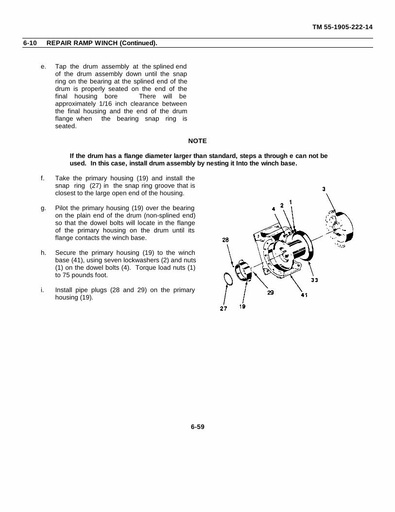
TM 55-1905-222-14
6-10 REPAIR RAMP WINCH (Continued).
e. Tap the drum assembly at the splined endof the drum assembly down until the snapring on the bearing at the splined end of thedrum is properly seated on the end of thefinal housing bore There will beapproximately 1/16 inch clearance betweenthe final housing and the end of the drumflange when the bearing snap ring isseated.
NOTE
If the drum has a flange diameter larger than standard, steps a through e can not beused. In this case, install drum assembly by nesting it Into the winch base.
f. Take the primary housing (19) and install thesnap ring (27) in the snap ring groove that isclosest to the large open end of the housing.
g. Pilot the primary housing (19) over the bearingon the plain end of the drum (non-splined end)so that the dowel bolts will locate in the flangeof the primary housing on the drum until itsflange contacts the winch base.
h. Secure the primary housing (19) to the winchbase (41), using seven lockwashers (2) and nuts(1) on the dowel bolts (4). Torque load nuts (1)to 75 pounds foot.
i. Install pipe plugs (28 and 29) on the primaryhousing (19).
6-59
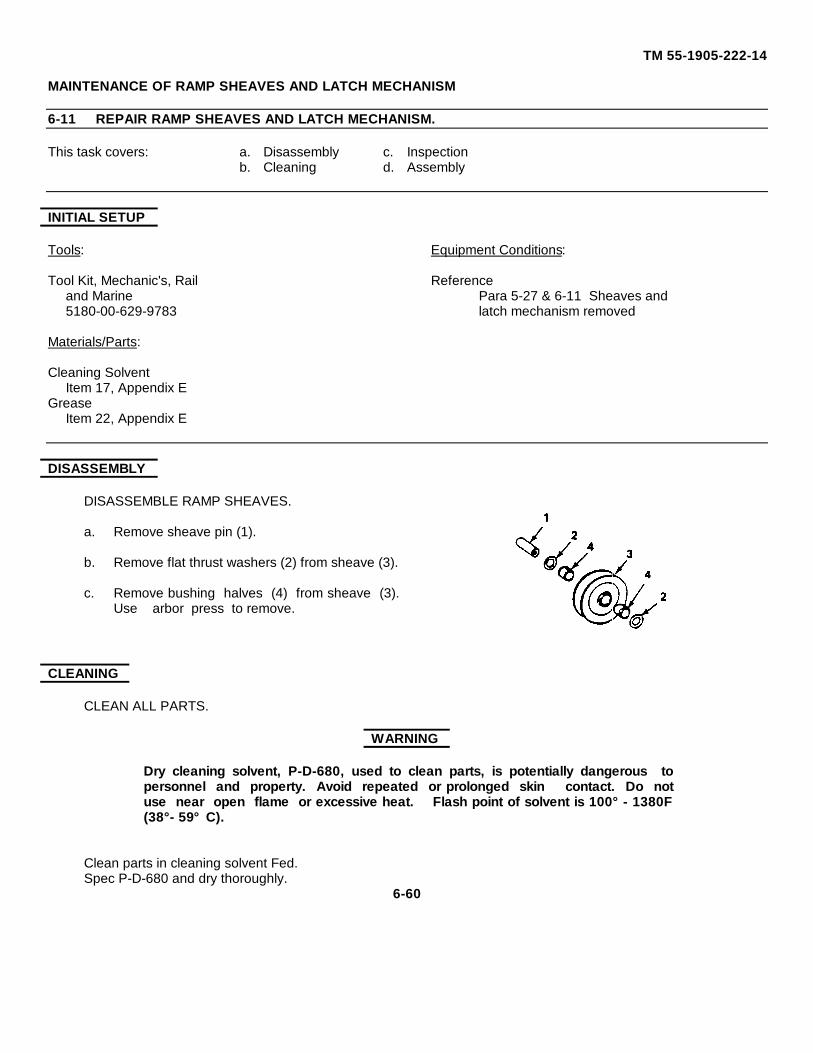
TM 55-1905-222-14
MAINTENANCE OF RAMP SHEAVES AND LATCH MECHANISM
6-11 REPAIR RAMP SHEAVES AND LATCH MECHANISM.
This task covers: a. Disassembly c. Inspectionb. Cleaning d. Assembly
INITIAL SETUP
Tools: Equipment Conditions:
Tool Kit, Mechanic's, Rail Referenceand Marine Para 5-27 & 6-11 Sheaves and5180-00-629-9783 latch mechanism removed
Materials/Parts:
Cleaning SolventItem 17, Appendix E
GreaseItem 22, Appendix E
DISASSEMBLY
DISASSEMBLE RAMP SHEAVES.
a. Remove sheave pin (1).
b. Remove flat thrust washers (2) from sheave (3).
c. Remove bushing halves (4) from sheave (3).Use arbor press to remove.
CLEANING
CLEAN ALL PARTS.
WARNING
Dry cleaning solvent, P-D-680, used to clean parts, is potentially dangerous topersonnel and property. Avoid repeated or prolonged skin contact. Do notuse near open flame or excessive heat. Flash point of solvent is 100° - 1380F(38°- 59°C).
Clean parts in cleaning solvent Fed.Spec P-D-680 and dry thoroughly.
6-60
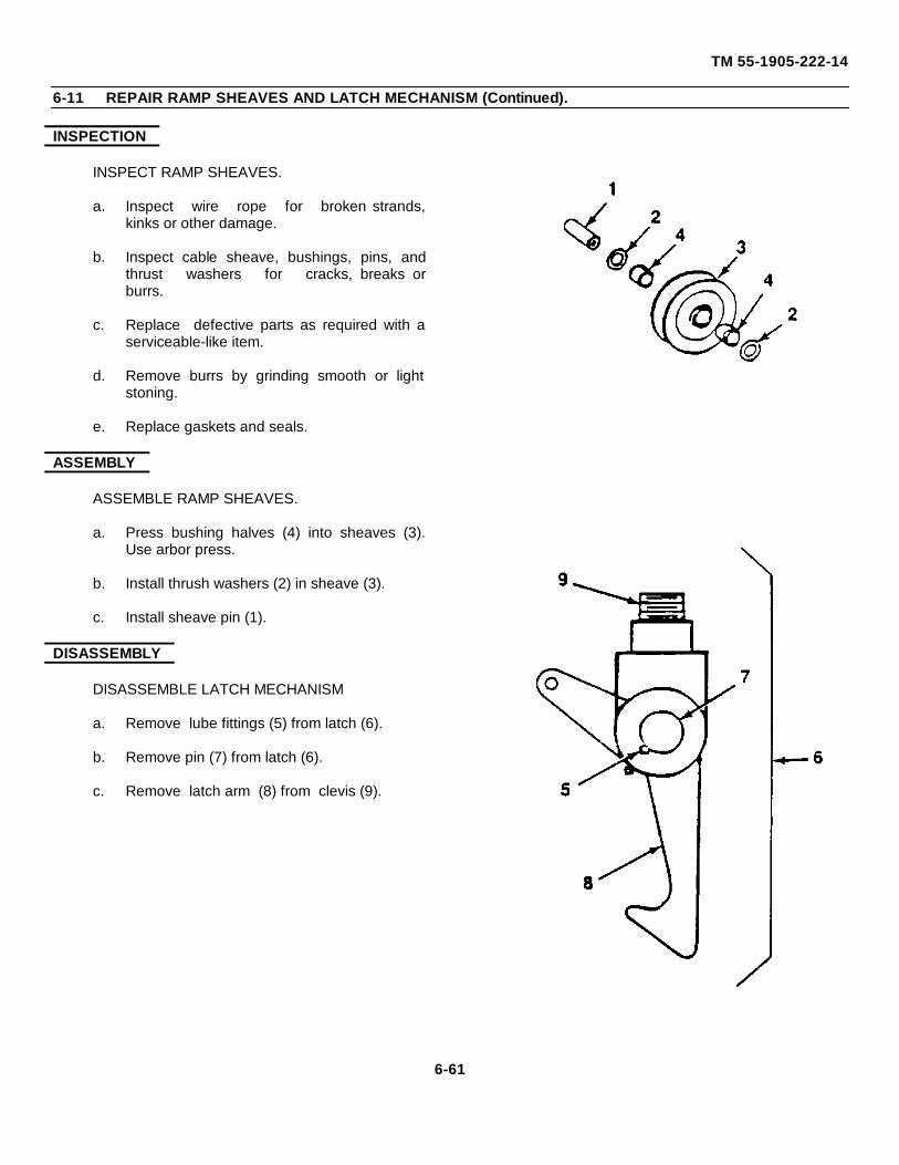
TM 55-1905-222-14
6-11 REPAIR RAMP SHEAVES AND LATCH MECHANISM (Continued).
INSPECTION
INSPECT RAMP SHEAVES.
a. Inspect wire rope for broken strands,kinks or other damage.
b. Inspect cable sheave, bushings, pins, andthrust washers for cracks, breaks orburrs.
c. Replace defective parts as required with aserviceable-like item.
d. Remove burrs by grinding smooth or lightstoning.
e. Replace gaskets and seals.
ASSEMBLY
ASSEMBLE RAMP SHEAVES.
a. Press bushing halves (4) into sheaves (3).Use arbor press.
b. Install thrush washers (2) in sheave (3).
c. Install sheave pin (1).
DISASSEMBLY
DISASSEMBLE LATCH MECHANISM
a. Remove lube fittings (5) from latch (6).
b. Remove pin (7) from latch (6).
c. Remove latch arm (8) from clevis (9).
6-61
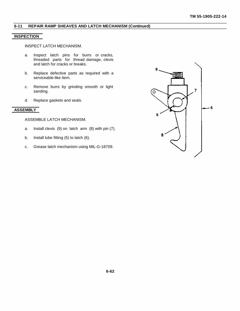
TM 55-1905-222-14
6-11 REPAIR RAMP SHEAVES AND LATCH MECHANISM (Continued)
INSPECTION
INSPECT LATCH MECHANISM.
a. Inspect latch pins for burrs or cracks,threaded parts for thread damage, clevisand latch for cracks or breaks.
b. Replace defective parts as required with aserviceable-like item.
c. Remove burrs by grinding smooth or lightsanding.
d. Replace gaskets and seals.
ASSEMBLY
ASSEMBLE LATCH MECHANISM.
a. Install clevis (9) on latch arm (8) with pin (7).
b. Install lube fitting (5) to latch (6).
c. Grease latch mechanism using MIL-G-18709.
6-62
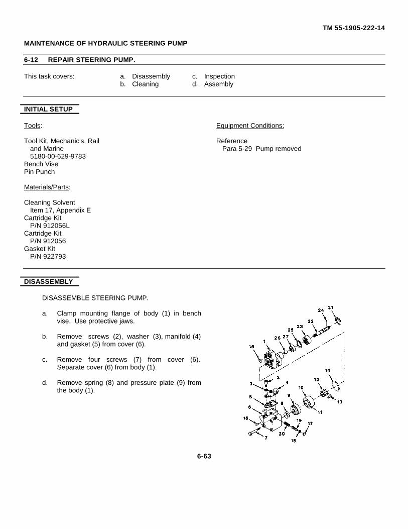
TM 55-1905-222-14
MAINTENANCE OF HYDRAULIC STEERING PUMP
6-12 REPAIR STEERING PUMP.
This task covers: a. Disassembly c. Inspectionb. Cleaning d. Assembly
INITIAL SETUP
Tools: Equipment Conditions:
Tool Kit, Mechanic's, Rail Referenceand Marine Para 5-29 Pump removed5180-00-629-9783
Bench VisePin Punch
Materials/Parts:
Cleaning SolventItem 17, Appendix E
Cartridge KitP/N 912056L
Cartridge KitP/N 912056
Gasket KitP/N 922793
DISASSEMBLY
DISASSEMBLE STEERING PUMP.
a. Clamp mounting flange of body (1) in benchvise. Use protective jaws.
b. Remove screws (2), washer (3), manifold (4)and gasket (5) from cover (6).
c. Remove four screws (7) from cover (6).Separate cover (6) from body (1).
d. Remove spring (8) and pressure plate (9) fromthe body (1).
6-63
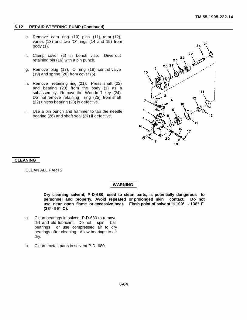
TM 55-1905-222-14
6-12 REPAIR STEERING PUMP (Continued).
e. Remove cam ring (10), pins (11), rotor (12),vanes (13) and two 'O' rings (14 and 15) frombody (1).
f. Clamp cover (6) in bench vise. Drive outretaining pin (16) with a pin punch.
g. Remove plug (17), 'O' ring (18), control valve(19) and spring (20) from cover (6).
h. Remove retaining ring (21). Press shaft (22)and bearing (23) from the body (1) as asubassembly. Remove the Woodruff key (24).Do not remove retaining ring (25) from shaft(22) unless bearing (23) is defective.
i. Use a pin punch and hammer to tap the needlebearing (26) and shaft seal (27) if defective.
CLEANING
CLEAN ALL PARTS
WARNING
Dry cleaning solvent, P-D-680, used to clean parts, is potentially dangerous topersonnel and property. Avoid repeated or prolonged skin contact. Do notuse near open flame or excessive heat. Flash point of solvent is 100° - 138°F(38°- 59°C).
a. Clean bearings in solvent P-D-680 to removedirt and old lubricant. Do not spin ballbearings or use compressed air to drybearings after cleaning. Allow bearings to airdry.
b. Clean metal parts in solvent P-D- 680.
6-64
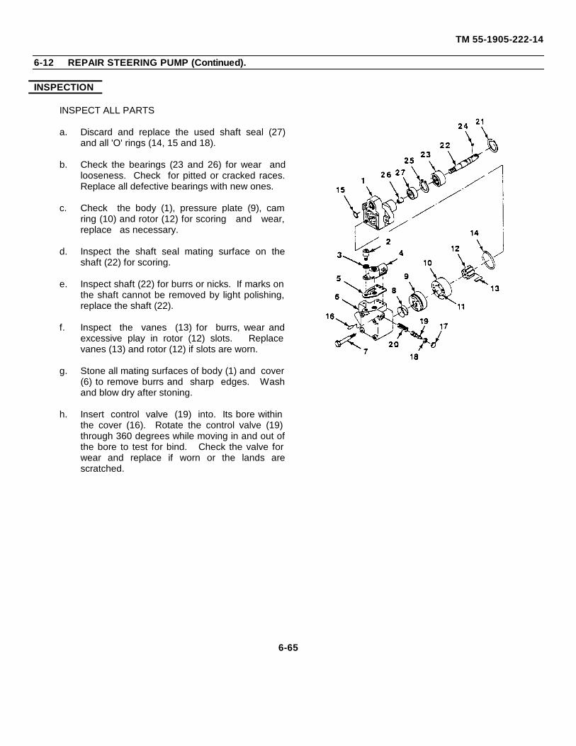
TM 55-1905-222-14
6-12 REPAIR STEERING PUMP (Continued).
INSPECTION
INSPECT ALL PARTS
a. Discard and replace the used shaft seal (27)and all 'O' rings (14, 15 and 18).
b. Check the bearings (23 and 26) for wear andlooseness. Check for pitted or cracked races.Replace all defective bearings with new ones.
c. Check the body (1), pressure plate (9), camring (10) and rotor (12) for scoring and wear,replace as necessary.
d. Inspect the shaft seal mating surface on theshaft (22) for scoring.
e. Inspect shaft (22) for burrs or nicks. If marks onthe shaft cannot be removed by light polishing,replace the shaft (22).
f. Inspect the vanes (13) for burrs, wear andexcessive play in rotor (12) slots. Replacevanes (13) and rotor (12) if slots are worn.
g. Stone all mating surfaces of body (1) and cover(6) to remove burrs and sharp edges. Washand blow dry after stoning.
h. Insert control valve (19) into. Its bore withinthe cover (16). Rotate the control valve (19)through 360 degrees while moving in and out ofthe bore to test for bind. Check the valve forwear and replace if worn or the lands arescratched.
6-65
TM 55-1905-222-14
6-12 REPAIR STEERING PUMP (Continued).
i. Inspect the valve plug (17) torque by firstplacing the control valve (19) in a benchvise, then tightening the vise enough toprevent the plunger from turning. Use atorque wrench and appropriate socket tocheck the torque of the valve plug (17). Theplug should be torqued to a value of 5 to 6 lbft.
ASSEMBLY
ASSEMBLE STEERING PUMP
NOTE
Tools for installing needle bearings can be made from round tubular stock. Theoutside diameter of the round stock must be slightly smaller than the outsidediameter of the needle bearing.
a. Press needle bearing (26) into body (1),using a needle bearing pressing tool (notedabove) and an arbor press.
NOTE
A shaft driver must be used to insure installation of the shaft seal without damage.
b. Position the shaft seal (27) with springside of seal facing body (1). Press shaft seal(27) in place until it engages the shoulderwithin the body.
c. If removed or found defective, press anew bearing (23) on shaft (22), using anarbor press. (All force should be applied tothe inner race of the bearing.)
d. Install the small retaining ring (25) in placewithin its groove on the shaft (22). (Thesharp break edge of the retaining ring mustbe facing the bearing at assembly.)
6-66
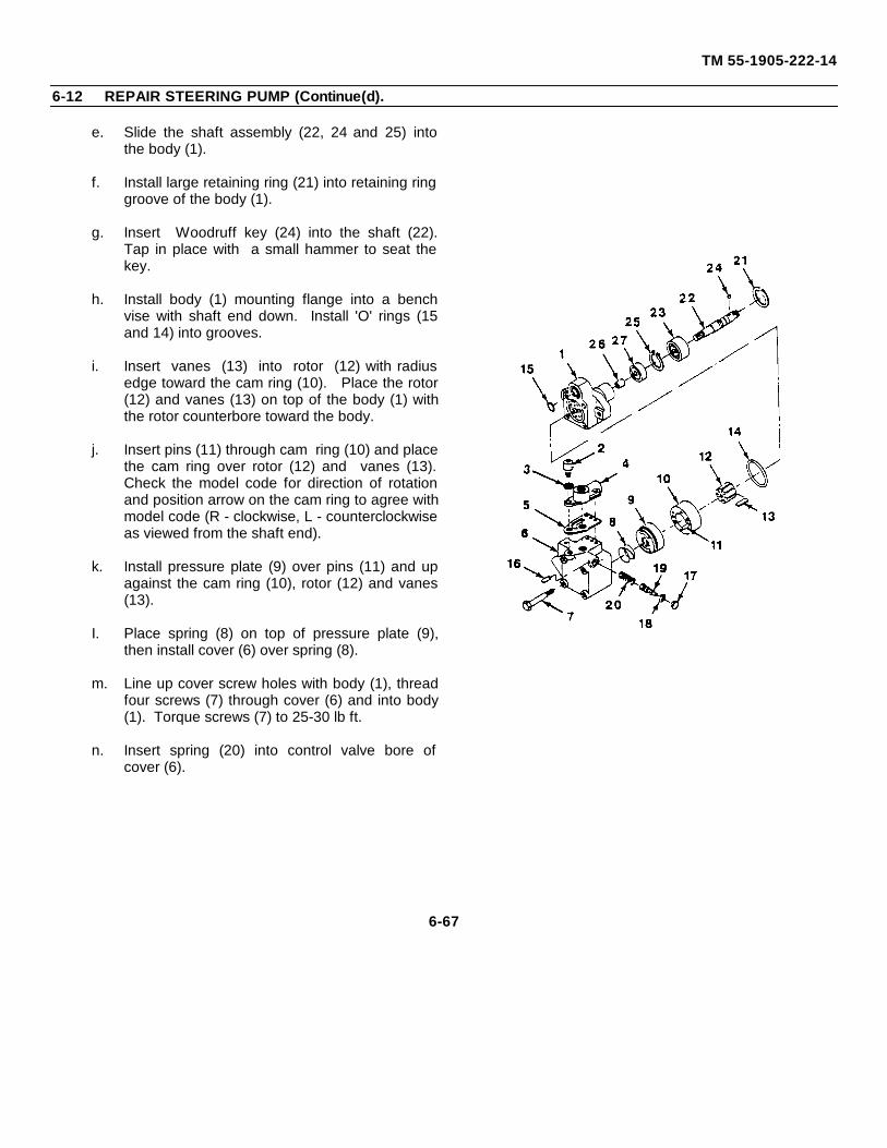
TM 55-1905-222-14
6-12 REPAIR STEERING PUMP (Continue(d).
e. Slide the shaft assembly (22, 24 and 25) intothe body (1).
f. Install large retaining ring (21) into retaining ringgroove of the body (1).
g. Insert Woodruff key (24) into the shaft (22).Tap in place with a small hammer to seat thekey.
h. Install body (1) mounting flange into a benchvise with shaft end down. Install 'O' rings (15and 14) into grooves.
i. Insert vanes (13) into rotor (12) with radiusedge toward the cam ring (10). Place the rotor(12) and vanes (13) on top of the body (1) withthe rotor counterbore toward the body.
j. Insert pins (11) through cam ring (10) and placethe cam ring over rotor (12) and vanes (13).Check the model code for direction of rotationand position arrow on the cam ring to agree withmodel code (R - clockwise, L - counterclockwiseas viewed from the shaft end).
k. Install pressure plate (9) over pins (11) and upagainst the cam ring (10), rotor (12) and vanes(13).
I. Place spring (8) on top of pressure plate (9),then install cover (6) over spring (8).
m. Line up cover screw holes with body (1), threadfour screws (7) through cover (6) and into body(1). Torque screws (7) to 25-30 lb ft.
n. Insert spring (20) into control valve bore ofcover (6).
6-67
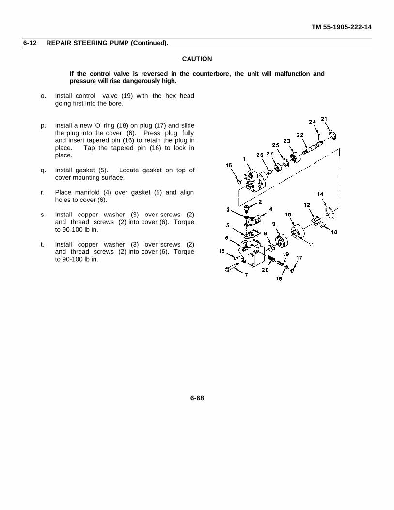
TM 55-1905-222-14
6-12 REPAIR STEERING PUMP (Continued).
CAUTION
If the control valve is reversed in the counterbore, the unit will malfunction andpressure will rise dangerously high.
o. Install control valve (19) with the hex headgoing first into the bore.
p. Install a new 'O' ring (18) on plug (17) and slidethe plug into the cover (6). Press plug fullyand insert tapered pin (16) to retain the plug inplace. Tap the tapered pin (16) to lock inplace.
q. Install gasket (5). Locate gasket on top ofcover mounting surface.
r. Place manifold (4) over gasket (5) and alignholes to cover (6).
s. Install copper washer (3) over screws (2)and thread screws (2) into cover (6). Torqueto 90-100 lb in.
t. Install copper washer (3) over screws (2)and thread screws (2) into cover (6). Torqueto 90-100 lb in.
6-68
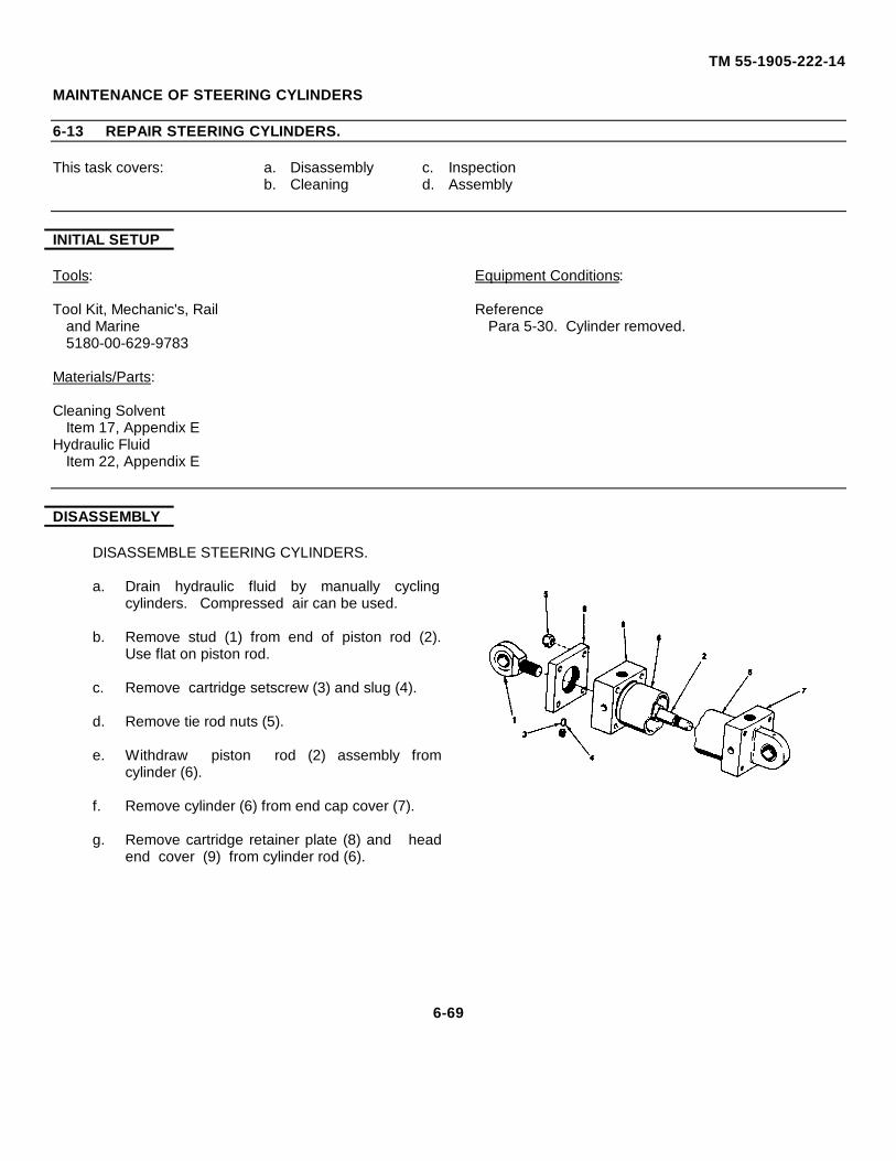
TM 55-1905-222-14
MAINTENANCE OF STEERING CYLINDERS
6-13 REPAIR STEERING CYLINDERS.
This task covers: a. Disassembly c. Inspectionb. Cleaning d. Assembly
INITIAL SETUP
Tools: Equipment Conditions:
Tool Kit, Mechanic's, Rail Referenceand Marine Para 5-30. Cylinder removed.5180-00-629-9783
Materials/Parts:
Cleaning SolventItem 17, Appendix E
Hydraulic FluidItem 22, Appendix E
DISASSEMBLY
DISASSEMBLE STEERING CYLINDERS.
a. Drain hydraulic fluid by manually cyclingcylinders. Compressed air can be used.
b. Remove stud (1) from end of piston rod (2).Use flat on piston rod.
c. Remove cartridge setscrew (3) and slug (4).
d. Remove tie rod nuts (5).
e. Withdraw piston rod (2) assembly fromcylinder (6).
f. Remove cylinder (6) from end cap cover (7).
g. Remove cartridge retainer plate (8) and headend cover (9) from cylinder rod (6).
6-69
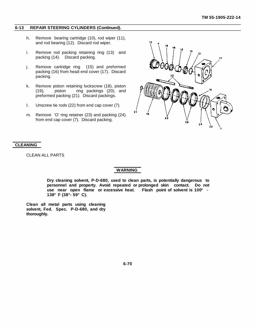
TM 55-1905-222-14
6-13 REPAIR STEERING CYLINDERS (Continued).
h. Remove bearing cartridge (10), rod wiper (11),and rod bearing (12). Discard rod wiper.
i. Remove rod packing retaining ring (13) andpacking (14). Discard packing.
j. Remove cartridge ring (15) and preformedpacking (16) from head end cover (17). Discardpacking.
k. Remove piston retaining lockscrew (18), piston(19), piston ring packings (20), andpreformed packing (21). Discard packings.
I. Unscrew tie rods (22) from end cap cover (7).
m. Remove 'O' ring retainer (23) and packing (24)from end cap cover (7). Discard packing.
CLEANING
CLEAN ALL PARTS
WARNING
Dry cleaning solvent, P-D-680, used to clean parts, is potentially dangerous topersonnel and property. Avoid repeated or prolonged skin contact. Do notuse near open flame or excessive heat. Flash point of solvent is 100° -138°F (38°- 59°C).
Clean all metal parts using cleaningsolvent, Fed. Spec. P-D-680, and drythoroughly.
6-70
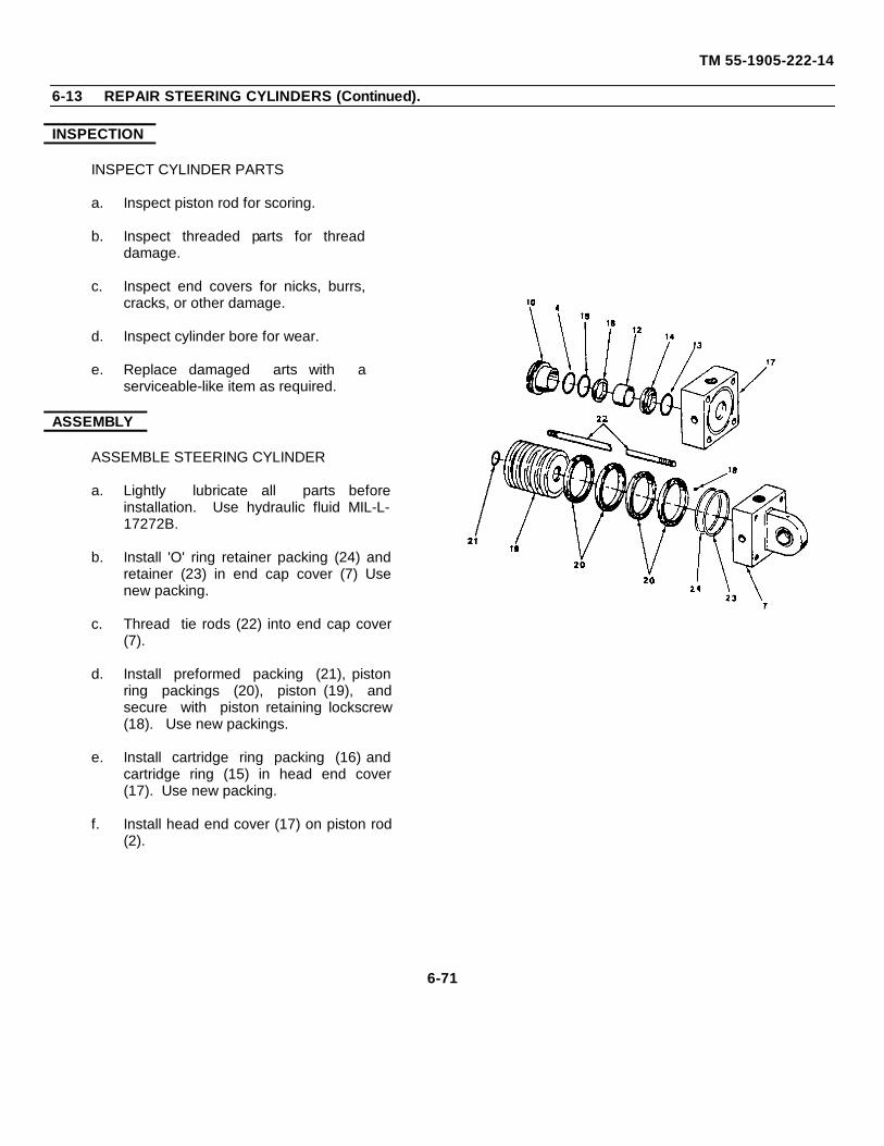
TM 55-1905-222-14
6-13 REPAIR STEERING CYLINDERS (Continued).
INSPECTION
INSPECT CYLINDER PARTS
a. Inspect piston rod for scoring.
b. Inspect threaded parts for threaddamage.
c. Inspect end covers for nicks, burrs,cracks, or other damage.
d. Inspect cylinder bore for wear.
e. Replace damaged arts with aserviceable-like item as required.
ASSEMBLY
ASSEMBLE STEERING CYLINDER
a. Lightly lubricate all parts beforeinstallation. Use hydraulic fluid MIL-L-17272B.
b. Install 'O' ring retainer packing (24) andretainer (23) in end cap cover (7) Usenew packing.
c. Thread tie rods (22) into end cap cover(7).
d. Install preformed packing (21), pistonring packings (20), piston (19), andsecure with piston retaining lockscrew(18). Use new packings.
e. Install cartridge ring packing (16) andcartridge ring (15) in head end cover(17). Use new packing.
f. Install head end cover (17) on piston rod(2).
6-71
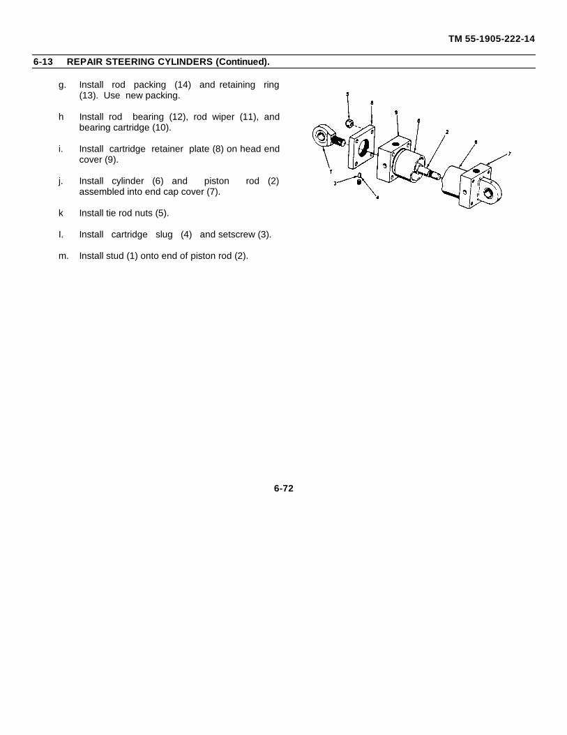
TM 55-1905-222-14
6-13 REPAIR STEERING CYLINDERS (Continued).
g. Install rod packing (14) and retaining ring(13). Use new packing.
h Install rod bearing (12), rod wiper (11), andbearing cartridge (10).
i. Install cartridge retainer plate (8) on head endcover (9).
j. Install cylinder (6) and piston rod (2)assembled into end cap cover (7).
k Install tie rod nuts (5).
I. Install cartridge slug (4) and setscrew (3).
m. Install stud (1) onto end of piston rod (2).
6-72
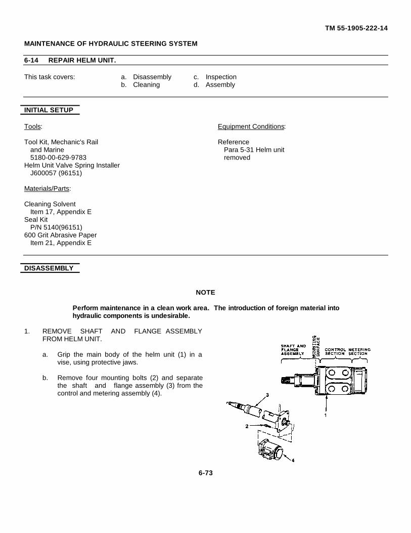
TM 55-1905-222-14
MAINTENANCE OF HYDRAULIC STEERING SYSTEM
6-14 REPAIR HELM UNIT.
This task covers: a. Disassembly c. Inspectionb. Cleaning d. Assembly
INITIAL SETUP
Tools: Equipment Conditions:
Tool Kit, Mechanic's Rail Referenceand Marine Para 5-31 Helm unit5180-00-629-9783 removed
Helm Unit Valve Spring InstallerJ600057 (96151)
Materials/Parts:
Cleaning SolventItem 17, Appendix E
Seal KitP/N 5140(96151)
600 Grit Abrasive PaperItem 21, Appendix E
DISASSEMBLY
NOTE
Perform maintenance in a clean work area. The introduction of foreign material intohydraulic components is undesirable.
1. REMOVE SHAFT AND FLANGE ASSEMBLYFROM HELM UNIT.
a. Grip the main body of the helm unit (1) in avise, using protective jaws.
b. Remove four mounting bolts (2) and separatethe shaft and flange assembly (3) from thecontrol and metering assembly (4).
6-73
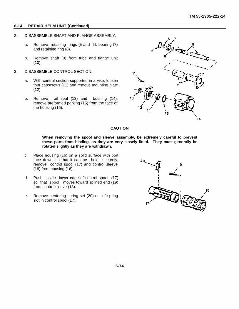
TM 55-1905-222-14
6-14 REPAIR HELM UNIT (Continued).
2. DISASSEMBLE SHAFT AND FLANGE ASSEMBLY.
a. Remove retaining rings (5 and 6), bearing (7)and retaining ring (8).
b. Remove shaft (9) from tube and flange unit(10).
3. DISASSEMBLE CONTROL SECTION.
a. With control section supported in a vise, loosenfour capscrews (11) and remove mounting plate(12).
b. Remove oil seal (13) and bushing (14);remove preformed parking (15) from the face ofthe housing (16).
CAUTION
When removing the spool and sleeve assembly, be extremely careful to preventthese parts from binding, as they are very closely fitted. They must generally berotated slightly as they are withdrawn.
c. Place housing (16) on a solid surface with portface down, so that it can be held securely,remove control spool (17) and control sleeve(18) from housing (16).
d. Push inside lower edge of control spool (17)so that spool moves toward splined end (19)from control sleeve (18).
e. Remove centering spring set (20) out of springslot in control spool (17).
6-74
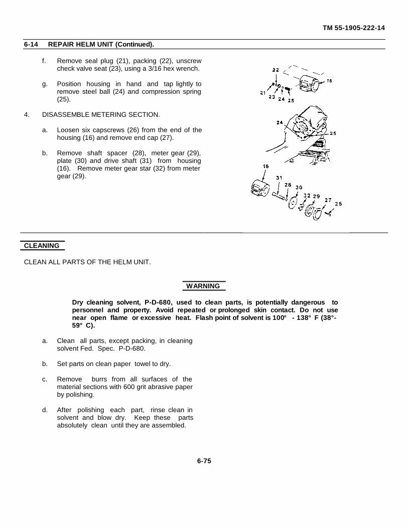
TM 55-1905-222-14
6-14 REPAIR HELM UNIT (Continued).
f. Remove seal plug (21), packing (22), unscrewcheck valve seat (23), using a 3/16 hex wrench.
g. Position housing in hand and tap lightly toremove steel ball (24) and compression spring(25).
4. DISASSEMBLE METERING SECTION.
a. Loosen six capscrews (26) from the end of thehousing (16) and remove end cap (27).
b. Remove shaft spacer (28), meter gear (29),plate (30) and drive shaft (31) from housing(16). Remove meter gear star (32) from metergear (29).
CLEANING
CLEAN ALL PARTS OF THE HELM UNIT.
WARNING
Dry cleaning solvent, P-D-680, used to clean parts, is potentially dangerous topersonnel and property. Avoid repeated or prolonged skin contact. Do not usenear open flame or excessive heat. Flash point of solvent is 100° - 138°F (38°-59°C).
a. Clean all parts, except packing, in cleaningsolvent Fed. Spec. P-D-680.
b. Set parts on clean paper towel to dry.
c. Remove burrs from all surfaces of thematerial sections with 600 grit abrasive paperby polishing.
d. After polishing each part, rinse clean insolvent and blow dry. Keep these partsabsolutely clean until they are assembled.
6-75
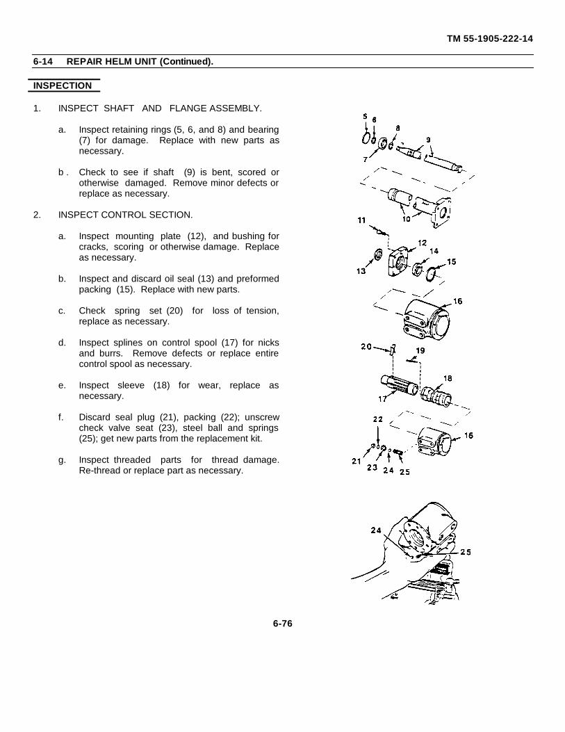
TM 55-1905-222-14
6-14 REPAIR HELM UNIT (Continued).
INSPECTION
1. INSPECT SHAFT AND FLANGE ASSEMBLY.
a. Inspect retaining rings (5, 6, and 8) and bearing(7) for damage. Replace with new parts asnecessary.
b . Check to see if shaft (9) is bent, scored orotherwise damaged. Remove minor defects orreplace as necessary.
2. INSPECT CONTROL SECTION.
a. Inspect mounting plate (12), and bushing forcracks, scoring or otherwise damage. Replaceas necessary.
b. Inspect and discard oil seal (13) and preformedpacking (15). Replace with new parts.
c. Check spring set (20) for loss of tension,replace as necessary.
d. Inspect splines on control spool (17) for nicksand burrs. Remove defects or replace entirecontrol spool as necessary.
e. Inspect sleeve (18) for wear, replace asnecessary.
f. Discard seal plug (21), packing (22); unscrewcheck valve seat (23), steel ball and springs(25); get new parts from the replacement kit.
g. Inspect threaded parts for thread damage.Re-thread or replace part as necessary.
6-76
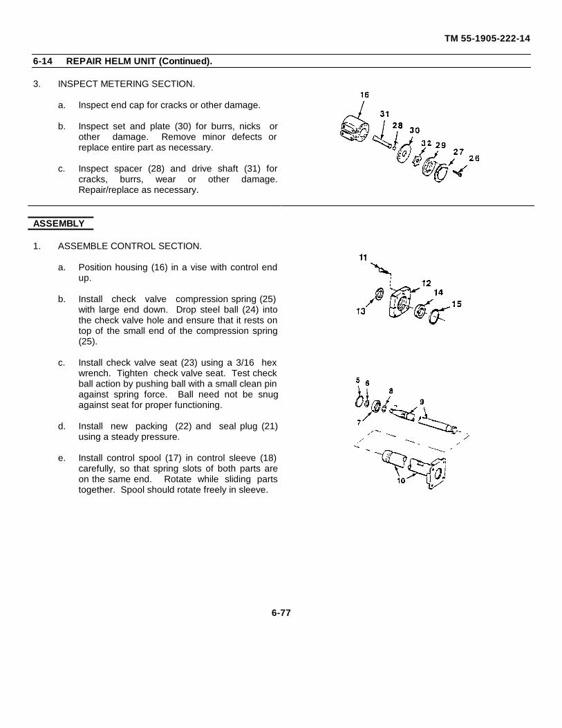
TM 55-1905-222-14
6-14 REPAIR HELM UNIT (Continued).
3. INSPECT METERING SECTION.
a. Inspect end cap for cracks or other damage.
b. Inspect set and plate (30) for burrs, nicks orother damage. Remove minor defects orreplace entire part as necessary.
c. Inspect spacer (28) and drive shaft (31) forcracks, burrs, wear or other damage.Repair/replace as necessary.
ASSEMBLY
1. ASSEMBLE CONTROL SECTION.
a. Position housing (16) in a vise with control endup.
b. Install check valve compression spring (25)with large end down. Drop steel ball (24) intothe check valve hole and ensure that it rests ontop of the small end of the compression spring(25).
c. Install check valve seat (23) using a 3/16 hexwrench. Tighten check valve seat. Test checkball action by pushing ball with a small clean pinagainst spring force. Ball need not be snugagainst seat for proper functioning.
d. Install new packing (22) and seal plug (21)using a steady pressure.
e. Install control spool (17) in control sleeve (18)carefully, so that spring slots of both parts areon the same end. Rotate while sliding partstogether. Spool should rotate freely in sleeve.
6-77
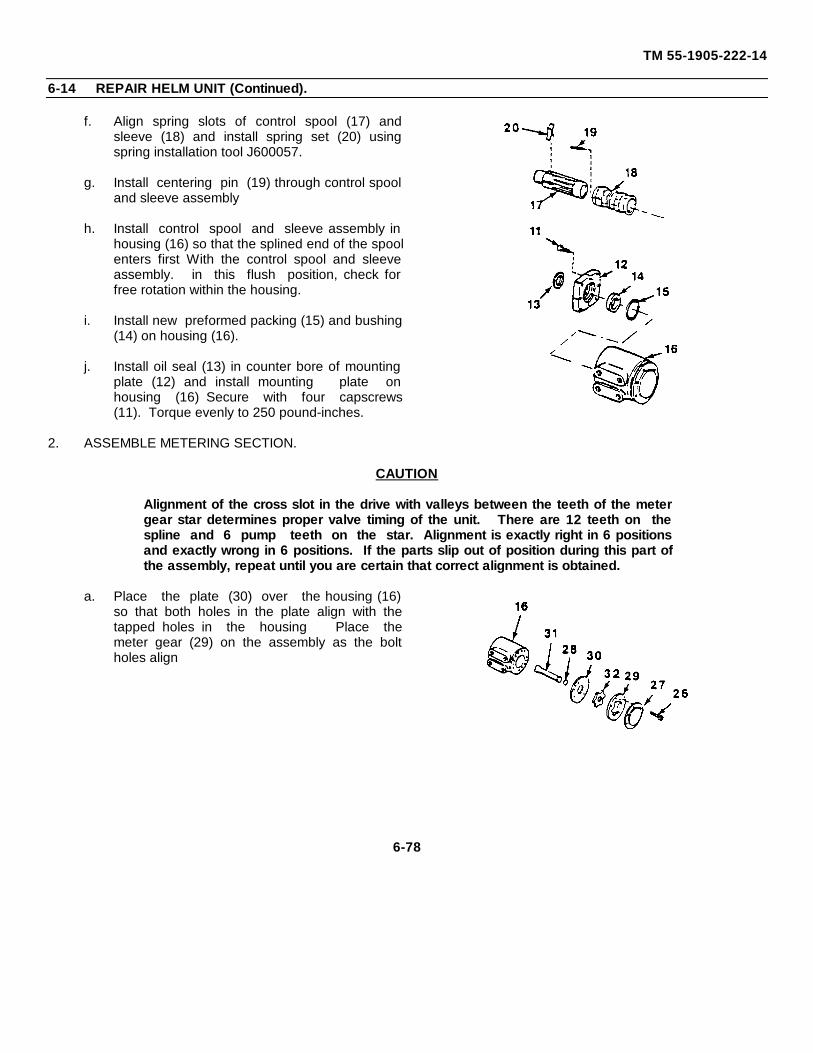
TM 55-1905-222-14
6-14 REPAIR HELM UNIT (Continued).
f. Align spring slots of control spool (17) andsleeve (18) and install spring set (20) usingspring installation tool J600057.
g. Install centering pin (19) through control spooland sleeve assembly
h. Install control spool and sleeve assembly inhousing (16) so that the splined end of the spoolenters first With the control spool and sleeveassembly. in this flush position, check forfree rotation within the housing.
i. Install new preformed packing (15) and bushing(14) on housing (16).
j. Install oil seal (13) in counter bore of mountingplate (12) and install mounting plate onhousing (16) Secure with four capscrews(11). Torque evenly to 250 pound-inches.
2. ASSEMBLE METERING SECTION.
CAUTION
Alignment of the cross slot in the drive with valleys between the teeth of the metergear star determines proper valve timing of the unit. There are 12 teeth on thespline and 6 pump teeth on the star. Alignment is exactly right in 6 positionsand exactly wrong in 6 positions. If the parts slip out of position during this part ofthe assembly, repeat until you are certain that correct alignment is obtained.
a. Place the plate (30) over the housing (16)so that both holes in the plate align with thetapped holes in the housing Place themeter gear (29) on the assembly as the boltholes align
6-78
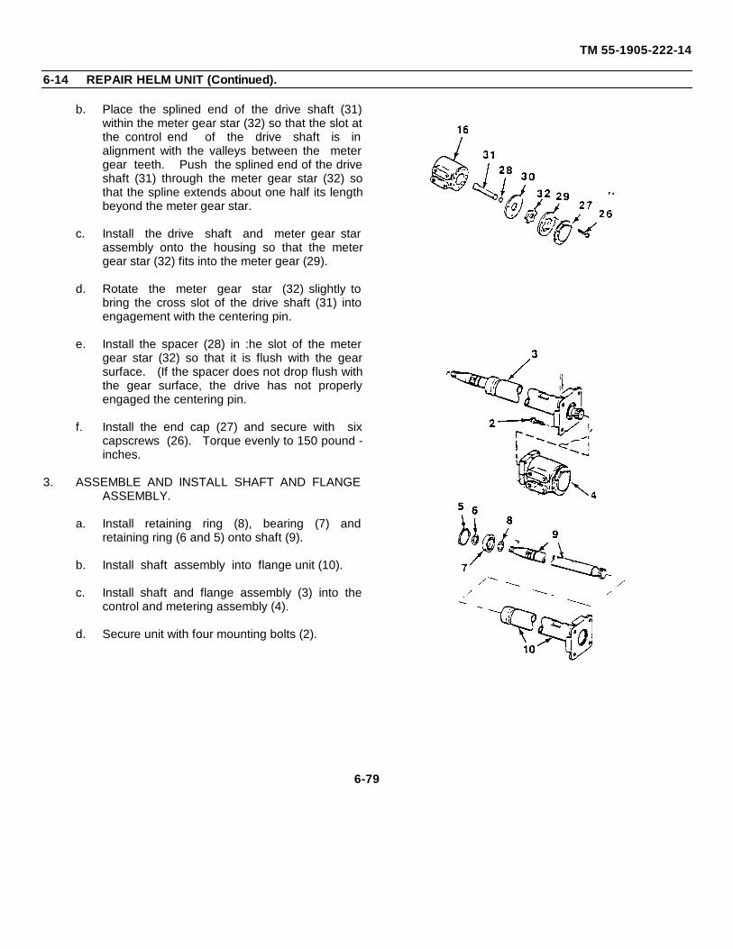
TM 55-1905-222-14
6-14 REPAIR HELM UNIT (Continued).
b. Place the splined end of the drive shaft (31)within the meter gear star (32) so that the slot atthe control end of the drive shaft is inalignment with the valleys between the metergear teeth. Push the splined end of the driveshaft (31) through the meter gear star (32) sothat the spline extends about one half its lengthbeyond the meter gear star.
c. Install the drive shaft and meter gear starassembly onto the housing so that the metergear star (32) fits into the meter gear (29).
d. Rotate the meter gear star (32) slightly tobring the cross slot of the drive shaft (31) intoengagement with the centering pin.
e. Install the spacer (28) in :he slot of the metergear star (32) so that it is flush with the gearsurface. (If the spacer does not drop flush withthe gear surface, the drive has not properlyengaged the centering pin.
f. Install the end cap (27) and secure with sixcapscrews (26). Torque evenly to 150 pound -inches.
3. ASSEMBLE AND INSTALL SHAFT AND FLANGEASSEMBLY.
a. Install retaining ring (8), bearing (7) andretaining ring (6 and 5) onto shaft (9).
b. Install shaft assembly into flange unit (10).
c. Install shaft and flange assembly (3) into thecontrol and metering assembly (4).
d. Secure unit with four mounting bolts (2).
6-79
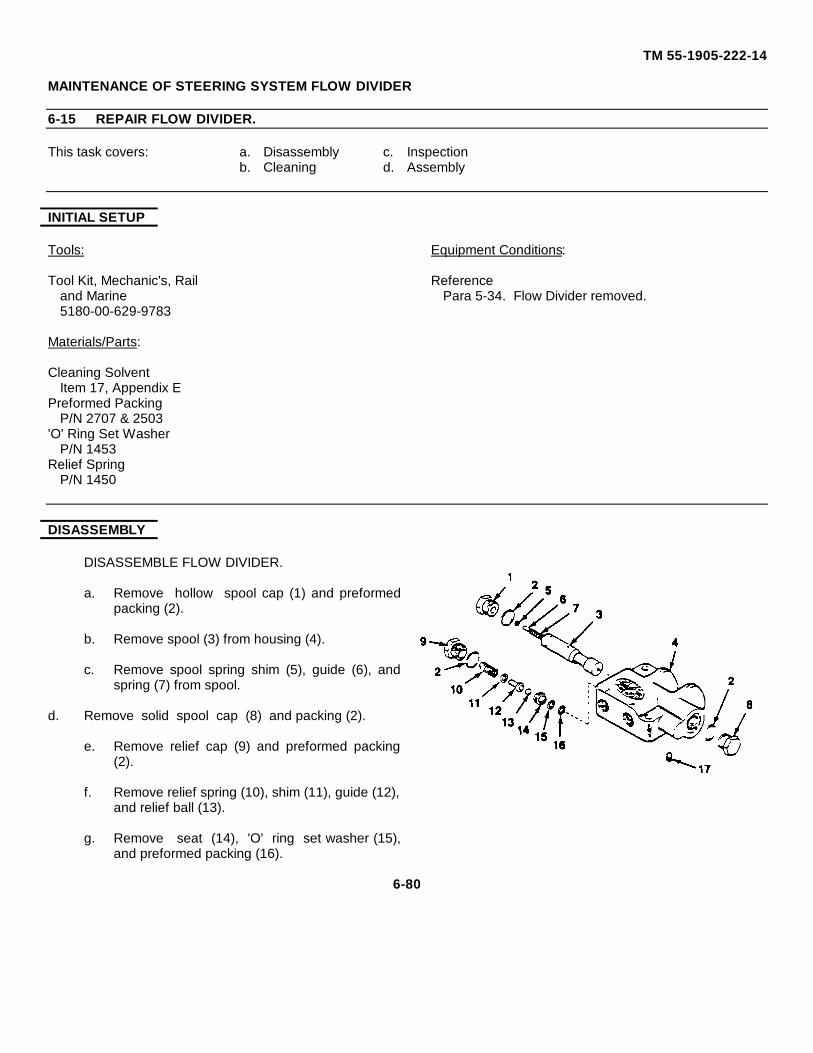
TM 55-1905-222-14
MAINTENANCE OF STEERING SYSTEM FLOW DIVIDER
6-15 REPAIR FLOW DIVIDER.
This task covers: a. Disassembly c. Inspectionb. Cleaning d. Assembly
INITIAL SETUP
Tools: Equipment Conditions:
Tool Kit, Mechanic's, Rail Referenceand Marine Para 5-34. Flow Divider removed.5180-00-629-9783
Materials/Parts:
Cleaning SolventItem 17, Appendix E
Preformed PackingP/N 2707 & 2503
'O' Ring Set WasherP/N 1453
Relief SpringP/N 1450
DISASSEMBLY
DISASSEMBLE FLOW DIVIDER.
a. Remove hollow spool cap (1) and preformedpacking (2).
b. Remove spool (3) from housing (4).
c. Remove spool spring shim (5), guide (6), andspring (7) from spool.
d. Remove solid spool cap (8) and packing (2).
e. Remove relief cap (9) and preformed packing(2).
f. Remove relief spring (10), shim (11), guide (12),and relief ball (13).
g. Remove seat (14), 'O' ring set washer (15),and preformed packing (16).
6-80
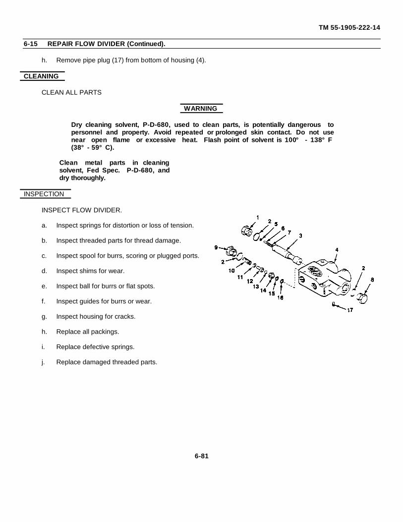
TM 55-1905-222-14
6-15 REPAIR FLOW DIVIDER (Continued).
h. Remove pipe plug (17) from bottom of housing (4).
CLEANING
CLEAN ALL PARTS
WARNING
Dry cleaning solvent, P-D-680, used to clean parts, is potentially dangerous topersonnel and property. Avoid repeated or prolonged skin contact. Do not usenear open flame or excessive heat. Flash point of solvent is 100° - 138°F(38°- 59°C).
Clean metal parts in cleaningsolvent, Fed Spec. P-D-680, anddry thoroughly.
INSPECTION
INSPECT FLOW DIVIDER.
a. Inspect springs for distortion or loss of tension.
b. Inspect threaded parts for thread damage.
c. Inspect spool for burrs, scoring or plugged ports.
d. Inspect shims for wear.
e. Inspect ball for burrs or flat spots.
f. Inspect guides for burrs or wear.
g. Inspect housing for cracks.
h. Replace all packings.
i. Replace defective springs.
j. Replace damaged threaded parts.
6-81
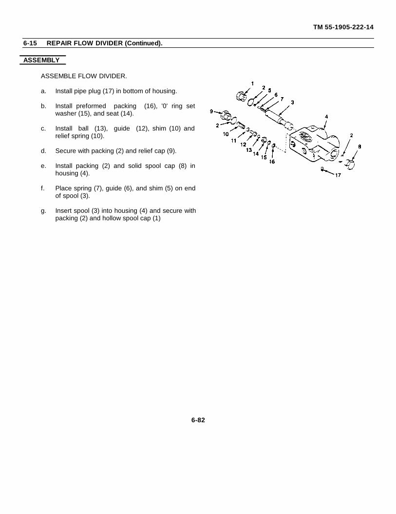
TM 55-1905-222-14
6-15 REPAIR FLOW DIVIDER (Continued).
ASSEMBLY
ASSEMBLE FLOW DIVIDER.
a. Install pipe plug (17) in bottom of housing.
b. Install preformed packing (16), '0' ring setwasher (15), and seat (14).
c. Install ball (13), guide (12), shim (10) andrelief spring (10).
d. Secure with packing (2) and relief cap (9).
e. Install packing (2) and solid spool cap (8) inhousing (4).
f. Place spring (7), guide (6), and shim (5) on endof spool (3).
g. Insert spool (3) into housing (4) and secure withpacking (2) and hollow spool cap (1)
6-82
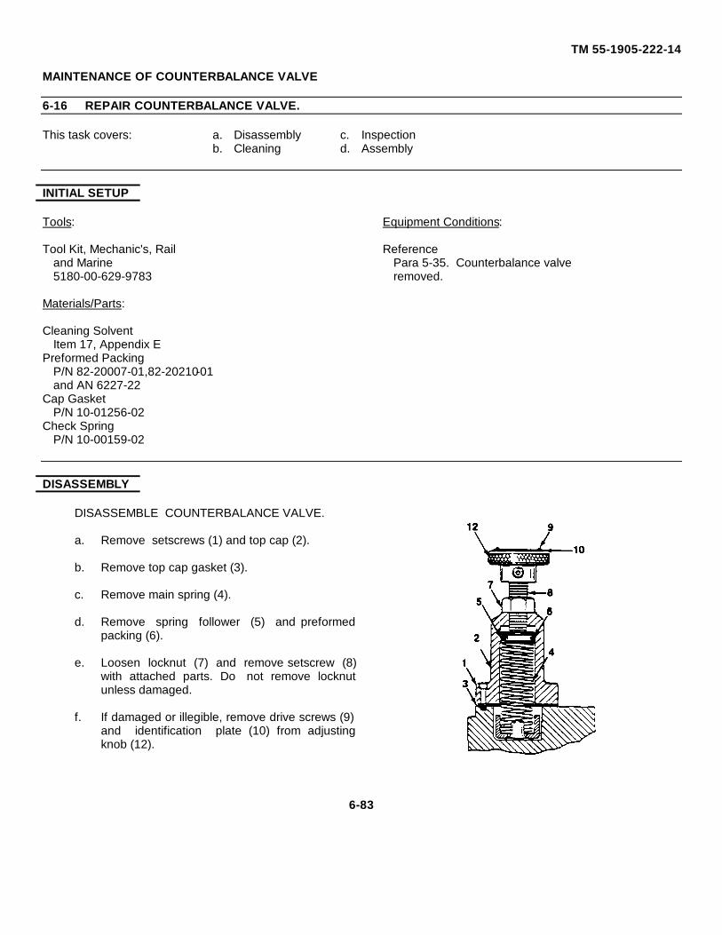
TM 55-1905-222-14
MAINTENANCE OF COUNTERBALANCE VALVE
6-16 REPAIR COUNTERBALANCE VALVE.
This task covers: a. Disassembly c. Inspectionb. Cleaning d. Assembly
INITIAL SETUP
Tools: Equipment Conditions:
Tool Kit, Mechanic's, Rail Referenceand Marine Para 5-35. Counterbalance valve5180-00-629-9783 removed.
Materials/Parts:
Cleaning SolventItem 17, Appendix E
Preformed PackingP/N 82-20007-01,82-20210-01and AN 6227-22
Cap GasketP/N 10-01256-02
Check SpringP/N 10-00159-02
DISASSEMBLY
DISASSEMBLE COUNTERBALANCE VALVE.
a. Remove setscrews (1) and top cap (2).
b. Remove top cap gasket (3).
c. Remove main spring (4).
d. Remove spring follower (5) and preformedpacking (6).
e. Loosen locknut (7) and remove setscrew (8)with attached parts. Do not remove locknutunless damaged.
f. If damaged or illegible, remove drive screws (9)and identification plate (10) from adjustingknob (12).
6-83
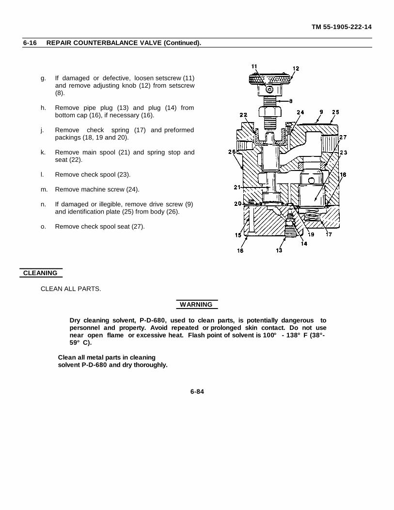
TM 55-1905-222-14
6-16 REPAIR COUNTERBALANCE VALVE (Continued).
g. If damaged or defective, loosen setscrew (11)and remove adjusting knob (12) from setscrew(8).
h. Remove pipe plug (13) and plug (14) frombottom cap (16), if necessary (16).
j. Remove check spring (17) and preformedpackings (18, 19 and 20).
k. Remove main spool (21) and spring stop andseat (22).
l. Remove check spool (23).
m. Remove machine screw (24).
n. If damaged or illegible, remove drive screw (9)and identification plate (25) from body (26).
o. Remove check spool seat (27).
CLEANING
CLEAN ALL PARTS.
WARNING
Dry cleaning solvent, P-D-680, used to clean parts, is potentially dangerous topersonnel and property. Avoid repeated or prolonged skin contact. Do not usenear open flame or excessive heat. Flash point of solvent is 100° - 138°F (38°-59°C).
Clean all metal parts in cleaningsolvent P-D-680 and dry thoroughly.
6-84
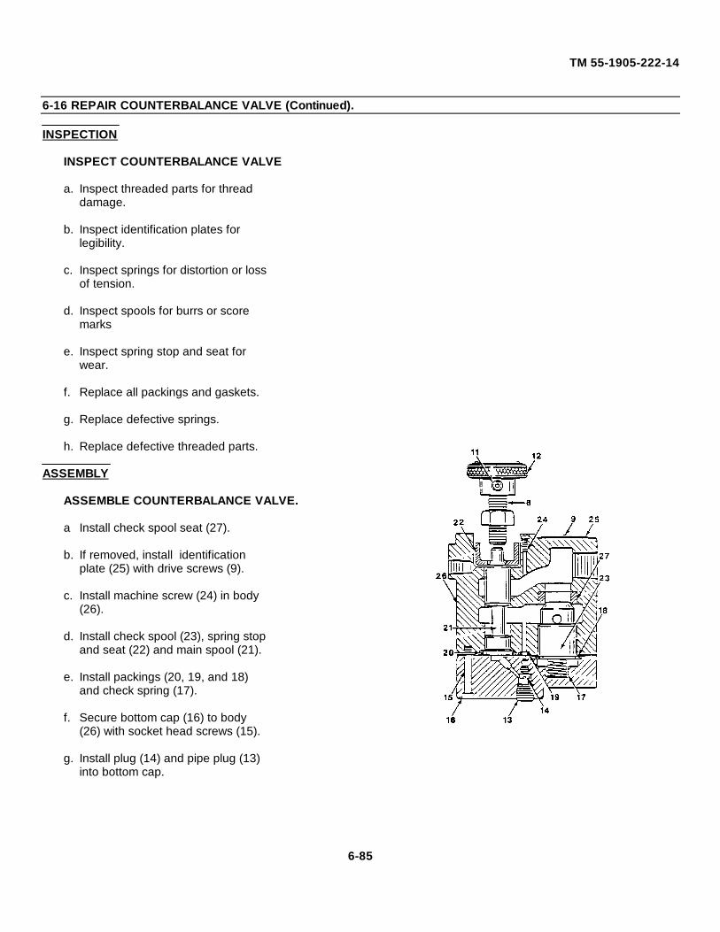
TM 55-1905-222-14
6-16 REPAIR COUNTERBALANCE VALVE (Continued).
INSPECTION
INSPECT COUNTERBALANCE VALVE
a. Inspect threaded parts for threaddamage.
b. Inspect identification plates forlegibility.
c. Inspect springs for distortion or lossof tension.
d. Inspect spools for burrs or scoremarks
e. Inspect spring stop and seat forwear.
f. Replace all packings and gaskets.
g. Replace defective springs.
h. Replace defective threaded parts.
ASSEMBLY
ASSEMBLE COUNTERBALANCE VALVE.
a Install check spool seat (27).
b. If removed, install identificationplate (25) with drive screws (9).
c. Install machine screw (24) in body(26).
d. Install check spool (23), spring stopand seat (22) and main spool (21).
e. Install packings (20, 19, and 18)and check spring (17).
f. Secure bottom cap (16) to body(26) with socket head screws (15).
g. Install plug (14) and pipe plug (13)into bottom cap.
6-85
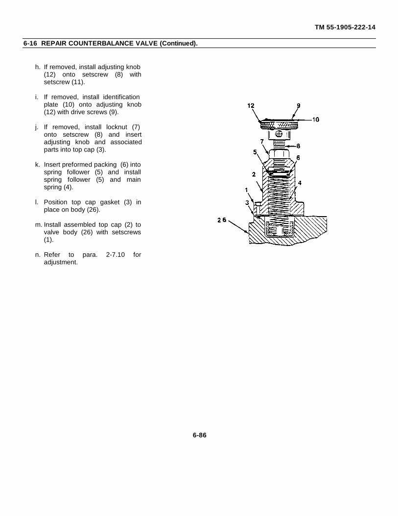
TM 55-1905-222-14
6-16 REPAIR COUNTERBALANCE VALVE (Continued).
h. If removed, install adjusting knob(12) onto setscrew (8) withsetscrew (11).
i. If removed, install identificationplate (10) onto adjusting knob(12) with drive screws (9).
j. If removed, install locknut (7)onto setscrew (8) and insertadjusting knob and associatedparts into top cap (3).
k. Insert preformed packing (6) intospring follower (5) and installspring follower (5) and mainspring (4).
l. Position top cap gasket (3) inplace on body (26).
m. Install assembled top cap (2) tovalve body (26) with setscrews(1).
n. Refer to para. 2-7.10 foradjustment.
6-86
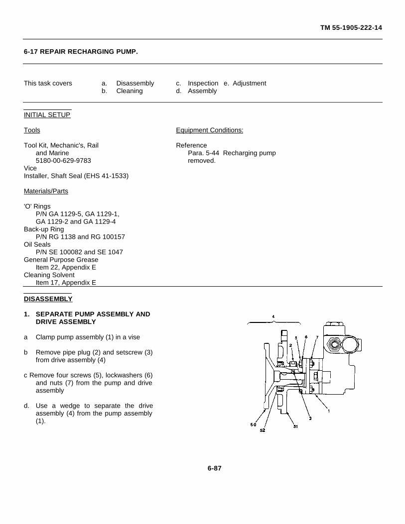
TM 55-1905-222-14
6-17 REPAIR RECHARGING PUMP.
This task covers a. Disassembly c. Inspection e. Adjustmentb. Cleaning d. Assembly
INITIAL SETUP
Tools Equipment Conditions:
Tool Kit, Mechanic's, Rail Referenceand Marine Para. 5-44 Recharging pump5180-00-629-9783 removed.
ViceInstaller, Shaft Seal (EHS 41-1533)
Materials/Parts
'O' RingsP/N GA 1129-5, GA 1129-1,GA 1129-2 and GA 1129-4
Back-up RingP/N RG 1138 and RG 100157
Oil SealsP/N SE 100082 and SE 1047
General Purpose GreaseItem 22, Appendix E
Cleaning SolventItem 17, Appendix E
DISASSEMBLY
1. SEPARATE PUMP ASSEMBLY ANDDRIVE ASSEMBLY
a Clamp pump assembly (1) in a vise
b Remove pipe plug (2) and setscrew (3)from drive assembly (4)
c Remove four screws (5), lockwashers (6)and nuts (7) from the pump and driveassembly
d. Use a wedge to separate the driveassembly (4) from the pump assembly(1).
6-87
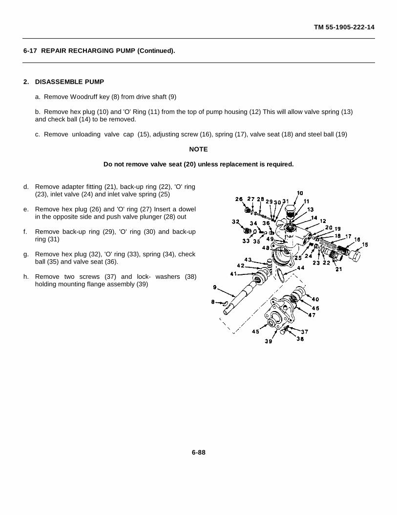
TM 55-1905-222-14
6-17 REPAIR RECHARGING PUMP (Continued).
2. DISASSEMBLE PUMP
a. Remove Woodruff key (8) from drive shaft (9)
b. Remove hex plug (10) and 'O' Ring (11) from the top of pump housing (12) This will allow valve spring (13)and check ball (14) to be removed.
c. Remove unloading valve cap (15), adjusting screw (16), spring (17), valve seat (18) and steel ball (19)
NOTE
Do not remove valve seat (20) unless replacement is required.
d. Remove adapter fitting (21), back-up ring (22), 'O' ring(23), inlet valve (24) and inlet valve spring (25)
e. Remove hex plug (26) and 'O' ring (27) Insert a dowelin the opposite side and push valve plunger (28) out
f. Remove back-up ring (29), 'O' ring (30) and back-upring (31)
g. Remove hex plug (32), 'O' ring (33), spring (34), checkball (35) and valve seat (36).
h. Remove two screws (37) and lock- washers (38)holding mounting flange assembly (39)
6-88
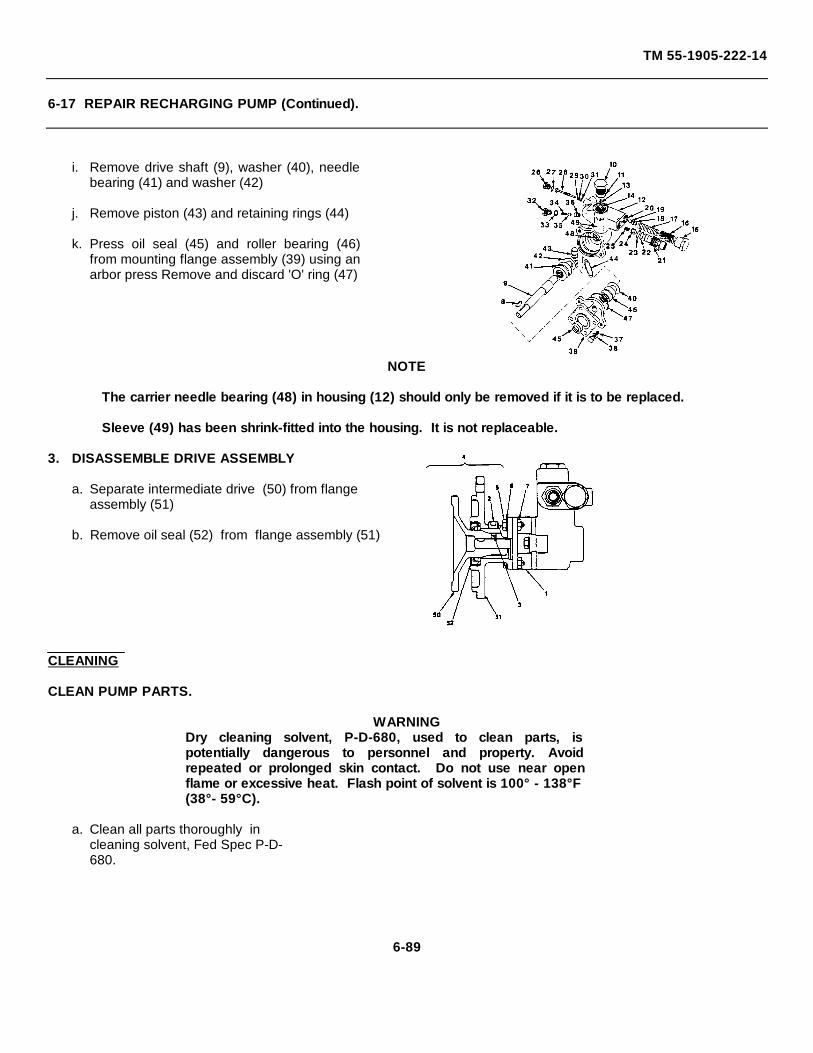
TM 55-1905-222-14
6-17 REPAIR RECHARGING PUMP (Continued).
i. Remove drive shaft (9), washer (40), needlebearing (41) and washer (42)
j. Remove piston (43) and retaining rings (44)
k. Press oil seal (45) and roller bearing (46)from mounting flange assembly (39) using anarbor press Remove and discard 'O' ring (47)
NOTE
The carrier needle bearing (48) in housing (12) should only be removed if it is to be replaced.
Sleeve (49) has been shrink-fitted into the housing. It is not replaceable.
3. DISASSEMBLE DRIVE ASSEMBLY
a. Separate intermediate drive (50) from flangeassembly (51)
b. Remove oil seal (52) from flange assembly (51)
CLEANING
CLEAN PUMP PARTS.
WARNINGDry cleaning solvent, P-D-680, used to clean parts, ispotentially dangerous to personnel and property. Avoidrepeated or prolonged skin contact. Do not use near openflame or excessive heat. Flash point of solvent is 100° - 138°F(38°- 59°C).
a. Clean all parts thoroughly incleaning solvent, Fed Spec P-D-680.
6-89
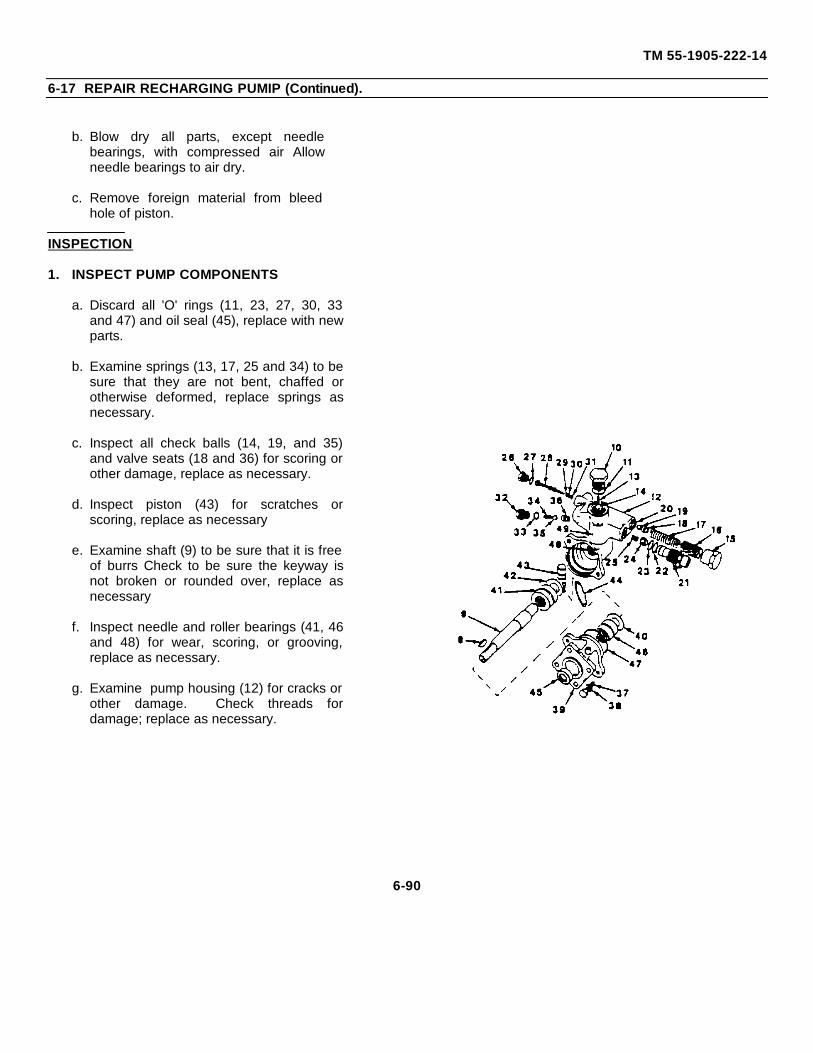
TM 55-1905-222-14
6-17 REPAIR RECHARGING PUMIP (Continued).
b. Blow dry all parts, except needlebearings, with compressed air Allowneedle bearings to air dry.
c. Remove foreign material from bleedhole of piston.
INSPECTION
1. INSPECT PUMP COMPONENTS
a. Discard all 'O' rings (11, 23, 27, 30, 33and 47) and oil seal (45), replace with newparts.
b. Examine springs (13, 17, 25 and 34) to besure that they are not bent, chaffed orotherwise deformed, replace springs asnecessary.
c. Inspect all check balls (14, 19, and 35)and valve seats (18 and 36) for scoring orother damage, replace as necessary.
d. Inspect piston (43) for scratches orscoring, replace as necessary
e. Examine shaft (9) to be sure that it is freeof burrs Check to be sure the keyway isnot broken or rounded over, replace asnecessary
f. Inspect needle and roller bearings (41, 46and 48) for wear, scoring, or grooving,replace as necessary.
g. Examine pump housing (12) for cracks orother damage. Check threads fordamage; replace as necessary.
6-90
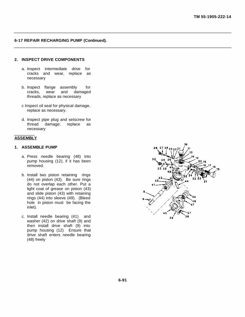
TM 55-1905-222-14
6-17 REPAIR RECHARGING PUMP (Continued).
2. INSPECT DRIVE COMPONENTS
a. Inspect intermediate drive forcracks and wear, replace asnecessary
b. Inspect flange assembly forcracks, wear and damagedthreads, replace as necessary
c Inspect oil seal for physical damage,replace as necessary.
d. Inspect pipe plug and setscrew forthread damage; replace asnecessary
ASSEMBLY
1. ASSEMBLE PUMP
a. Press needle bearing (48) intopump housing (12), if it has beenremoved.
b. Install two piston retaining rings(44) on piston (43). Be sure ringsdo not overlap each other. Put alight coat of grease on piston (43)and slide piston (43) with retainingrings (44) into sleeve (49). (Bleedhole in piston must be facing theinlet).
c. Install needle bearing (41) andwasher (42) on drive shaft (9) andthen install drive shaft (9) intopump housing (12) Ensure thatdrive shaft enters needle bearing(48) freely
6-91
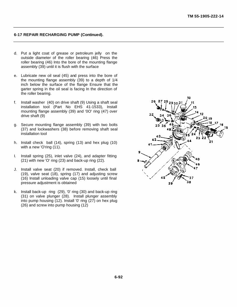
TM 55-1905-222-14
6-17 REPAIR RECHARGING PUMP (Continued).
d. Put a light coat of grease or petroleum jelly on theoutside diameter of the roller bearing (46) Press theroller bearing (46) Into the bore of the mounting flangeassembly (39) until it is flush with the surface
e. Lubricate new oil seal (45) and press into the bore ofthe mounting flange assembly (39) to a depth of 1/4inch below the surface of the flange Ensure that thegarter spring in the oil seal is facing In the direction ofthe roller bearing.
f. Install washer (40) on drive shaft (9) Using a shaft sealinstallation tool (Part No EHS 41-1533), Installmounting flange assembly (39) and '0O' ring (47) overdrive shaft (9)
g. Secure mounting flange assembly (39) with two bolts(37) and lockwashers (38) before removing shaft sealinstallation tool
h. Install check ball (14), spring (13) and hex plug (10)with a new 'O'ring (11).
I. Install spring (25), inlet valve (24), and adapter fitting(21) with new 'O' ring (23) and back-up ring (22).
J. Install valve seat (20) if removed. Install, check ball(19), valve seat (18), spring (17) and adjusting screw(16) Install unloading valve cap (15) loosely until finalpressure adjustment is obtained
k. Install back-up ring (29), '0' ring (30) and back-up ring(31) on valve plunger (28). Install plunger assemblyinto pump housing (12). Install '0' ring (27) on hex plug(26) and screw into pump housing (12)
6-92
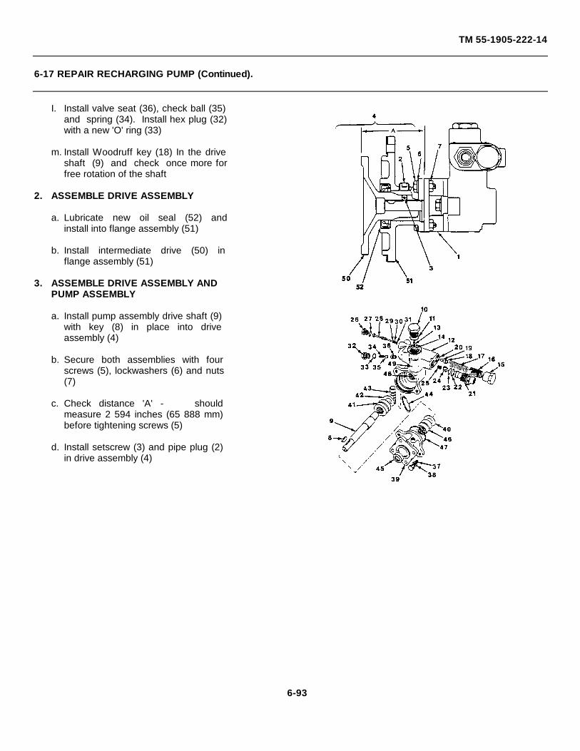
TM 55-1905-222-14
6-17 REPAIR RECHARGING PUMP (Continued).
I. Install valve seat (36), check ball (35)and spring (34). Install hex plug (32)with a new 'O' ring (33)
m. Install Woodruff key (18) In the driveshaft (9) and check once more forfree rotation of the shaft
2. ASSEMBLE DRIVE ASSEMBLY
a. Lubricate new oil seal (52) andinstall into flange assembly (51)
b. Install intermediate drive (50) inflange assembly (51)
3. ASSEMBLE DRIVE ASSEMBLY ANDPUMP ASSEMBLY
a. Install pump assembly drive shaft (9)with key (8) in place into driveassembly (4)
b. Secure both assemblies with fourscrews (5), lockwashers (6) and nuts(7)
c. Check distance 'A' - shouldmeasure 2 594 inches (65 888 mm)before tightening screws (5)
d. Install setscrew (3) and pipe plug (2)in drive assembly (4)
6-93
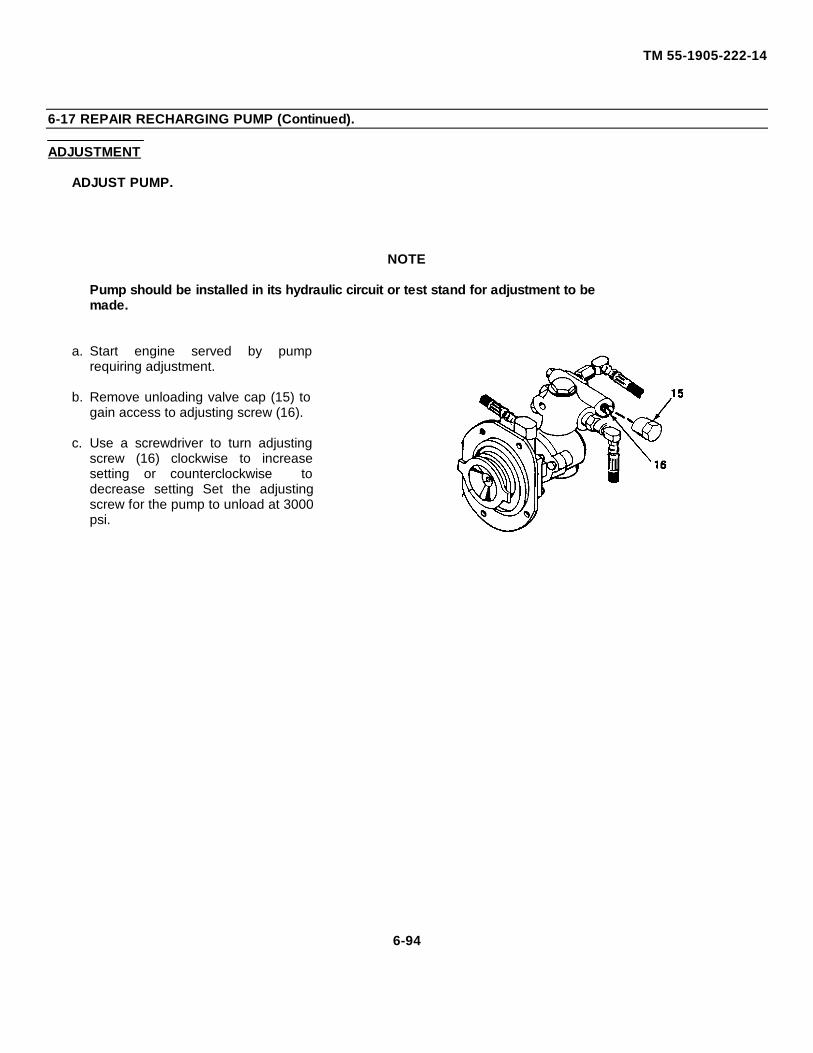
TM 55-1905-222-14
6-17 REPAIR RECHARGING PUMP (Continued).
ADJUSTMENT
ADJUST PUMP.
NOTE
Pump should be installed in its hydraulic circuit or test stand for adjustment to bemade.
a. Start engine served by pumprequiring adjustment.
b. Remove unloading valve cap (15) togain access to adjusting screw (16).
c. Use a screwdriver to turn adjustingscrew (16) clockwise to increasesetting or counterclockwise todecrease setting Set the adjustingscrew for the pump to unload at 3000psi.
6-94
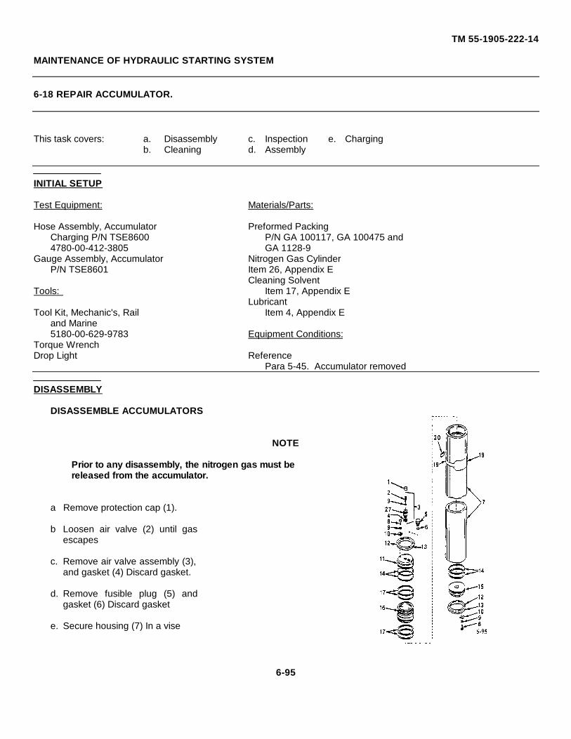
TM 55-1905-222-14
MAINTENANCE OF HYDRAULIC STARTING SYSTEM
6-18 REPAIR ACCUMULATOR.
This task covers: a. Disassembly c. Inspection e. Chargingb. Cleaning d. Assembly
INITIAL SETUP
Test Equipment: Materials/Parts:
Hose Assembly, Accumulator Preformed PackingCharging P/N TSE8600 P/N GA 100117, GA 100475 and4780-00-412-3805 GA 1128-9
Gauge Assembly, Accumulator Nitrogen Gas CylinderP/N TSE8601 Item 26, Appendix E
Cleaning SolventTools: Item 17, Appendix E
LubricantTool Kit, Mechanic's, Rail Item 4, Appendix E
and Marine5180-00-629-9783 Equipment Conditions:
Torque WrenchDrop Light Reference
Para 5-45. Accumulator removed
DISASSEMBLY
DISASSEMBLE ACCUMULATORS
NOTE
Prior to any disassembly, the nitrogen gas must bereleased from the accumulator.
a Remove protection cap (1).
b Loosen air valve (2) until gasescapes
c. Remove air valve assembly (3),and gasket (4) Discard gasket.
d. Remove fusible plug (5) andgasket (6) Discard gasket
e. Secure housing (7) In a vise
6-95
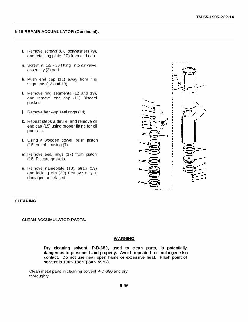
TM 55-1905-222-14
6-18 REPAIR ACCUMULATOR (Continued).
f. Remove screws (8), lockwashers (9),and retaining plate (10) from end cap.
g. Screw a 1/2 - 20 fitting into air valveassembly (3) port.
h. Push end cap (11) away from ringsegments (12 and 13).
I. Remove ring segments (12 and 13),and remove end cap (11) Discardgaskets.
j. Remove back-up seal rings (14).
k. Repeat steps a thru e. and remove oilend cap (15) using proper fitting for oilport size.
I. Using a wooden dowel, push piston(16) out of housing (7).
m. Remove seal rings (17) from piston(16) Discard gaskets.
n. Remove nameplate (18), strap (19)and locking clip (20) Remove only ifdamaged or defaced.
CLEANING
CLEAN ACCUMULATOR PARTS.
WARNING
Dry cleaning solvent, P-D-680, used to clean parts, is potentiallydangerous to personnel and property. Avoid repeated or prolonged skincontact. Do not use near open flame or excessive heat. Flash point ofsolvent is 100°- 138°F( 38°- 59°C).
Clean metal parts in cleaning solvent P-D-680 and drythoroughly.
6-96
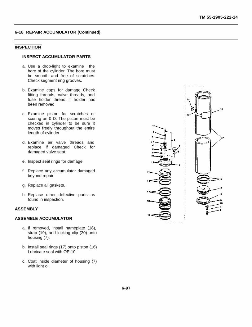
TM 55-1905-222-14
6-18 REPAIR ACCUMULATOR (Continued).
INSPECTION
INSPECT ACCUMULATOR PARTS
a. Use a drop-light to examine thebore of the cylinder. The bore mustbe smooth and free of scratches.Check segment ring grooves.
b. Examine caps for damage Checkfitting threads, valve threads, andfuse holder thread if holder hasbeen removed
c. Examine piston for scratches orscoring on 0 D. The piston must bechecked in cylinder to be sure itmoves freely throughout the entirelength of cylinder
d. Examine air valve threads andreplace if damaged Check fordamaged valve seat.
e. Inspect seal rings for damage
f. Replace any accumulator damagedbeyond repair.
g. Replace all gaskets.
h. Replace other defective parts asfound in inspection.
ASSEMBLY
ASSEMBLE ACCUMULATOR
a. If removed, install nameplate (18),strap (19), and locking clip (20) ontohousing (7).
b. Install seal rings (17) onto piston (16)Lubricate seal with OE-10.
c. Coat inside diameter of housing (7)with light oil.
6-97
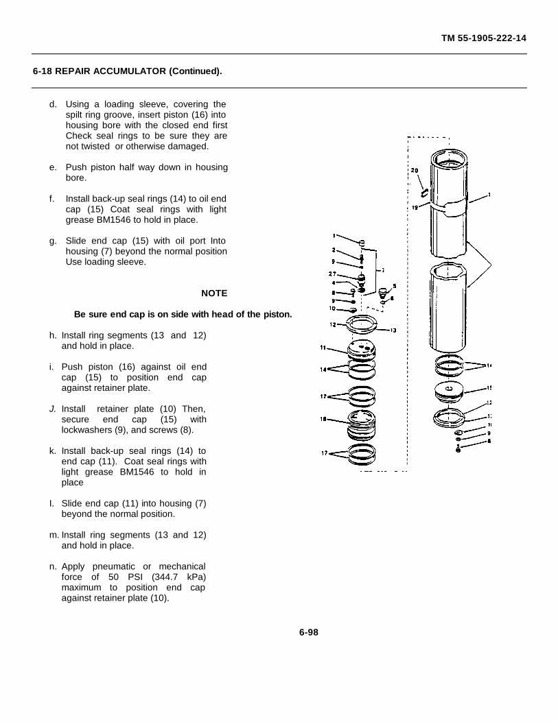
TM 55-1905-222-14
6-18 REPAIR ACCUMULATOR (Continued).
d. Using a loading sleeve, covering thespilt ring groove, insert piston (16) intohousing bore with the closed end firstCheck seal rings to be sure they arenot twisted or otherwise damaged.
e. Push piston half way down in housingbore.
f. Install back-up seal rings (14) to oil endcap (15) Coat seal rings with lightgrease BM1546 to hold in place.
g. Slide end cap (15) with oil port Intohousing (7) beyond the normal positionUse loading sleeve.
NOTE
Be sure end cap is on side with head of the piston.
h. Install ring segments (13 and 12)and hold in place.
i. Push piston (16) against oil endcap (15) to position end capagainst retainer plate.
J. Install retainer plate (10) Then,secure end cap (15) withlockwashers (9), and screws (8).
k. Install back-up seal rings (14) toend cap (11). Coat seal rings withlight grease BM1546 to hold inplace
I. Slide end cap (11) into housing (7)beyond the normal position.
m. Install ring segments (13 and 12)and hold in place.
n. Apply pneumatic or mechanicalforce of 50 PSI (344.7 kPa)maximum to position end capagainst retainer plate (10).
6-98
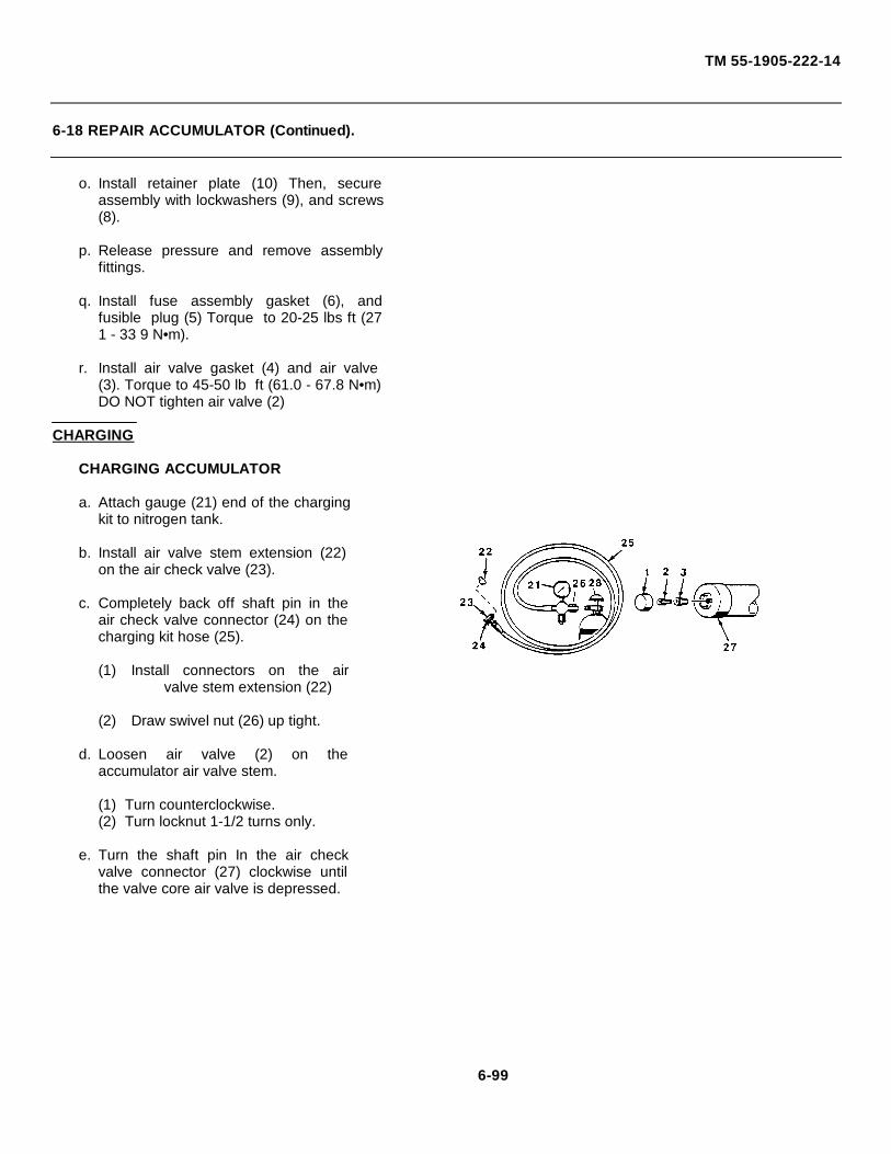
TM 55-1905-222-14
6-18 REPAIR ACCUMULATOR (Continued).
o. Install retainer plate (10) Then, secureassembly with lockwashers (9), and screws(8).
p. Release pressure and remove assemblyfittings.
q. Install fuse assembly gasket (6), andfusible plug (5) Torque to 20-25 lbs ft (271 - 33 9 N•m).
r. Install air valve gasket (4) and air valve(3). Torque to 45-50 lb ft (61.0 - 67.8 N•m)DO NOT tighten air valve (2)
CHARGING
CHARGING ACCUMULATOR
a. Attach gauge (21) end of the chargingkit to nitrogen tank.
b. Install air valve stem extension (22)on the air check valve (23).
c. Completely back off shaft pin in theair check valve connector (24) on thecharging kit hose (25).
(1) Install connectors on the airvalve stem extension (22)
(2) Draw swivel nut (26) up tight.
d. Loosen air valve (2) on theaccumulator air valve stem.
(1) Turn counterclockwise.(2) Turn locknut 1-1/2 turns only.
e. Turn the shaft pin In the air checkvalve connector (27) clockwise untilthe valve core air valve is depressed.
6-99
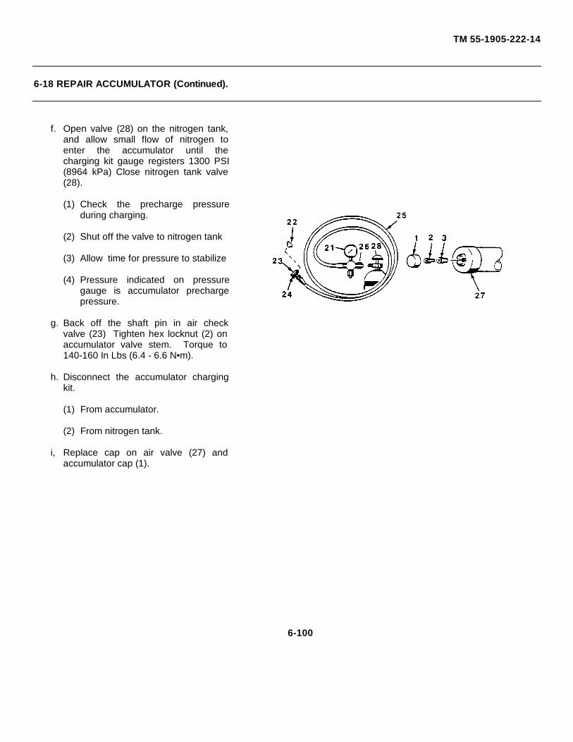
TM 55-1905-222-14
6-18 REPAIR ACCUMULATOR (Continued).
f. Open valve (28) on the nitrogen tank,and allow small flow of nitrogen toenter the accumulator until thecharging kit gauge registers 1300 PSI(8964 kPa) Close nitrogen tank valve(28).
(1) Check the precharge pressureduring charging.
(2) Shut off the valve to nitrogen tank
(3) Allow time for pressure to stabilize
(4) Pressure indicated on pressuregauge is accumulator prechargepressure.
g. Back off the shaft pin in air checkvalve (23) Tighten hex locknut (2) onaccumulator valve stem. Torque to140-160 In Lbs (6.4 - 6.6 N•m).
h. Disconnect the accumulator chargingkit.
(1) From accumulator.
(2) From nitrogen tank.
i, Replace cap on air valve (27) andaccumulator cap (1).
6-100
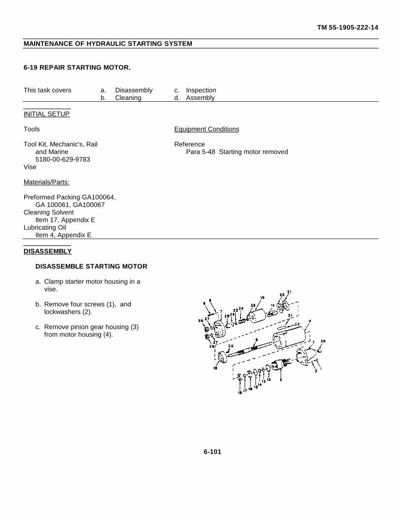
TM 55-1905-222-14
MAINTENANCE OF HYDRAULIC STARTING SYSTEM
6-19 REPAIR STARTING MOTOR.
This task covers a. Disassembly c. Inspectionb. Cleaning d. Assembly
INITIAL SETUP
Tools Equipment Conditions
Tool Kit, Mechanic's, Rail Referenceand Marine Para 5-48 Starting motor removed5180-00-629-9783
Vise
Materials/Parts:
Preformed Packing GA100064,GA 100061, GA100067
Cleaning SolventItem 17, Appendix E
Lubricating OilItem 4, Appendix E
DISASSEMBLY
DISASSEMBLE STARTING MOTOR
a. Clamp starter motor housing in avise.
b. Remove four screws (1), andlockwashers (2).
c. Remove pinion gear housing (3)from motor housing (4).
6-101
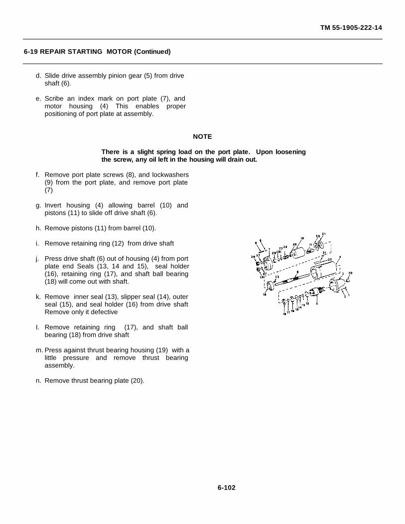
TM 55-1905-222-14
6-19 REPAIR STARTING MOTOR (Continued)
d. Slide drive assembly pinion gear (5) from driveshaft (6).
e. Scribe an index mark on port plate (7), andmotor housing (4) This enables properpositioning of port plate at assembly.
NOTE
There is a slight spring load on the port plate. Upon looseningthe screw, any oil left in the housing will drain out.
f. Remove port plate screws (8), and lockwashers(9) from the port plate, and remove port plate(7)
g. Invert housing (4) allowing barrel (10) andpistons (11) to slide off drive shaft (6).
h. Remove pistons (11) from barrel (10).
i. Remove retaining ring (12) from drive shaft
j. Press drive shaft (6) out of housing (4) from portplate end Seals (13, 14 and 15), seal holder(16), retaining ring (17), and shaft ball bearing(18) will come out with shaft.
k. Remove inner seal (13), slipper seal (14), outerseal (15), and seal holder (16) from drive shaftRemove only it defective
I. Remove retaining ring (17), and shaft ballbearing (18) from drive shaft
m. Press against thrust bearing housing (19) with alittle pressure and remove thrust bearingassembly.
n. Remove thrust bearing plate (20).
6-102
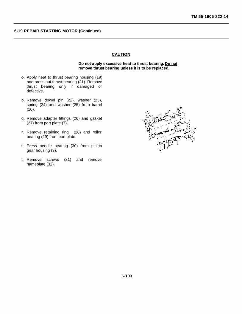
TM 55-1905-222-14
6-19 REPAIR STARTING MOTOR (Continued)
CAUTION
Do not apply excessive heat to thrust bearing. Do notremove thrust bearing unless it is to be replaced.
o. Apply heat to thrust bearing housing (19)and press out thrust bearing (21). Removethrust bearing only if damaged ordefective.
p. Remove dowel pin (22), washer (23),spring (24) and washer (25) from barrel(10).
q. Remove adapter fittings (26) and gasket(27) from port plate (7).
r. Remove retaining ring (28) and rollerbearing (29) from port plate.
s. Press needle bearing (30) from piniongear housing (3).
t. Remove screws (31) and removenameplate (32).
6-103
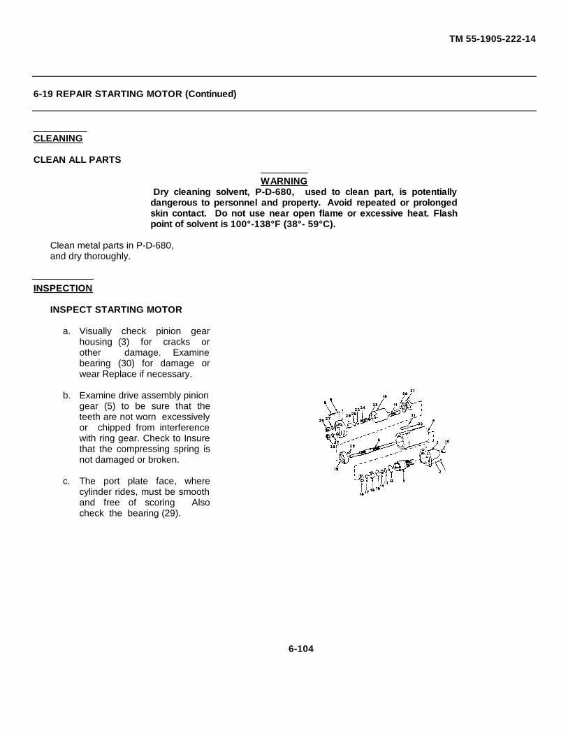
TM 55-1905-222-14
6-19 REPAIR STARTING MOTOR (Continued)
CLEANING
CLEAN ALL PARTS
WARNING Dry cleaning solvent, P-D-680, used to clean part, is potentiallydangerous to personnel and property. Avoid repeated or prolongedskin contact. Do not use near open flame or excessive heat. Flashpoint of solvent is 100°-138°F (38°- 59°C).
Clean metal parts in P-D-680,and dry thoroughly.
INSPECTION
INSPECT STARTING MOTOR
a. Visually check pinion gearhousing (3) for cracks orother damage. Examinebearing (30) for damage orwear Replace if necessary.
b. Examine drive assembly piniongear (5) to be sure that theteeth are not worn excessivelyor chipped from interferencewith ring gear. Check to Insurethat the compressing spring isnot damaged or broken.
c. The port plate face, wherecylinder rides, must be smoothand free of scoring Alsocheck the bearing (29).
6-104
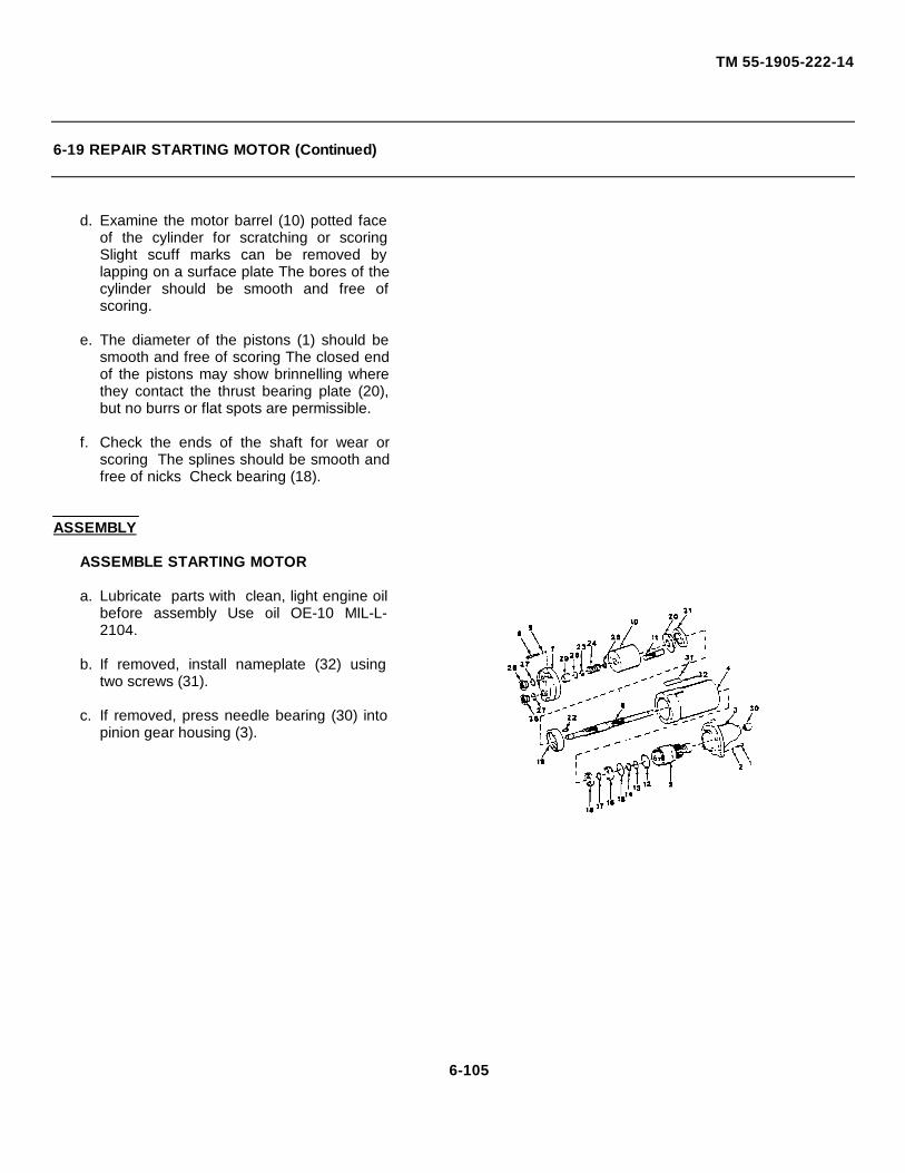
TM 55-1905-222-14
6-19 REPAIR STARTING MOTOR (Continued)
d. Examine the motor barrel (10) potted faceof the cylinder for scratching or scoringSlight scuff marks can be removed bylapping on a surface plate The bores of thecylinder should be smooth and free ofscoring.
e. The diameter of the pistons (1) should besmooth and free of scoring The closed endof the pistons may show brinnelling wherethey contact the thrust bearing plate (20),but no burrs or flat spots are permissible.
f. Check the ends of the shaft for wear orscoring The splines should be smooth andfree of nicks Check bearing (18).
ASSEMBLY
ASSEMBLE STARTING MOTOR
a. Lubricate parts with clean, light engine oilbefore assembly Use oil OE-10 MIL-L-2104.
b. If removed, install nameplate (32) usingtwo screws (31).
c. If removed, press needle bearing (30) intopinion gear housing (3).
6-105
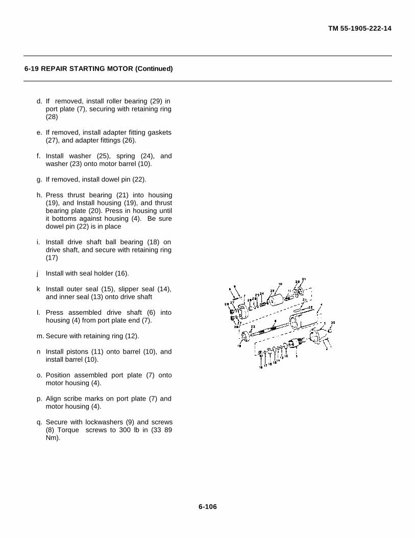
TM 55-1905-222-14
6-19 REPAIR STARTING MOTOR (Continued)
d. If removed, install roller bearing (29) inport plate (7), securing with retaining ring(28)
e. If removed, install adapter fitting gaskets(27), and adapter fittings (26).
f. Install washer (25), spring (24), andwasher (23) onto motor barrel (10).
g. If removed, install dowel pin (22).
h. Press thrust bearing (21) into housing(19), and Install housing (19), and thrustbearing plate (20). Press in housing untilit bottoms against housing (4). Be suredowel pin (22) is in place
i. Install drive shaft ball bearing (18) ondrive shaft, and secure with retaining ring(17)
j Install with seal holder (16).
k Install outer seal (15), slipper seal (14),and inner seal (13) onto drive shaft
I. Press assembled drive shaft (6) intohousing (4) from port plate end (7).
m. Secure with retaining ring (12).
n Install pistons (11) onto barrel (10), andinstall barrel (10).
o. Position assembled port plate (7) ontomotor housing (4).
p. Align scribe marks on port plate (7) andmotor housing (4).
q. Secure with lockwashers (9) and screws(8) Torque screws to 300 lb in (33 89Nm).
6-106
TM 55-1905-222-14
6-19 REPAIR STARTING MOTOR (Continued)
r. Install drive assembly pinion gear (5)onto drive shaft (6)
s Position pinion gear housing (3) in placeon motor housing (4)
t Secure with four lockwashers (2), andscrews (1) Tighten screws
6-107

TM 55-1905-222-14
MAINTENANCE OF HYDRAULIC STARTING SYSTEM
6-20 REPAIR HAND PUMP (STARTING SYSTEM).
This task covers: a. Disassembly c. Inspectionb. Cleaning d. Assembly
INITIAL SETUP
Tools:. Equipment Conditions:
Tool Kit, Mechanic's, Rail Referenceand Marine Para 5-49 Hand Pump removed5180-00-629-9783
Materials/Parts:
Repair Kit KT202565Cleaning Solvent
Item 17, Appendix ESealantCrocus Cloth
Item 20, Appendix E
DISASSEMBLY
DISASSEMBLE HAND PUMP
a. Pull pump handle grip (1) fromhand pump operating handle (2).Only if grip is damaged
b. Remove cotter pins (3) and (4)Lift handle (2) from operatinglever (5)
c. Remove retaining rings (6) fromclevis pin (7)
d. Remove retaining ring (8), clevispin (9), and links (10), to removehand pump operating lever (5)from the pump body (11)
e. Remove retaining rings (8),clevis pin (9), and links (10) fromplunger (12)
f. Remove bleeder screw (13), 'O'ring gasket (14), and bleeder ballvalve (15) from pump body (11)Discard 'O' ring gasket
6-108
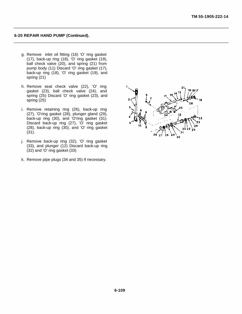
TM 55-1905-222-14
6-20 REPAIR HAND PUMP (Continued).
g. Remove inlet oil fitting (16) 'O' ring gasket(17), back-up ring (18), 'O' ring gasket (19),ball check valve (20), and spring (21) frompump body (11) Discard 'O' ring gasket (17),back-up ring (18), 'O' ring gasket (19), andspring (21)
h. Remove seat check valve (22), 'O' ringgasket (23), ball check valve (24), andspring (25) Discard 'O' ring gasket (23), andspring (25)
i. Remove retaining ring (26), back-up ring(27), 'O'ring gasket (28), plunger gland (29),back-up ring (30), and 'O'ring gasket (31).Discard back-up ring (27), 'O' ring gasket(28), back-up ring (30), and 'O' ring gasket(31).
j. Remove back-up ring (32), 'O' ring gasket(33), and plunger (12) Discard back-up ring(32) and 'O' ring gasket (33)
k. Remove pipe plugs (34 and 35) If necessary.
6-109
TM 55-1905-222-14
6-20 REPAIR HAND PUMP (Continued).
CLEAN
CLEAN ALL PARTS.
WARNING
Dry cleaning solvent, P-D-680, used to clean parts, is potentiallydangerous to personnel and property. Avoid repeated or prolongedskin contact. Do not use near open flame or excessive heat.Flash point of solvent is 100°-138°F (38°- 59°C).
Clean metal parts In cleaning solventP-D-680 and dry thoroughly
INSPECTION
INSPECT HAND PUMP
a. Inspect springs for distortion loss of tension or broken coils
b. Inspect pins, balls piston for burrs or nicks
c. Inspect hand grip for deterioration
d. Replace all packing and seals with new ones
e. Remove burrs or nicks with crocus cloth.
g. Replace all defective parts as required
6-110
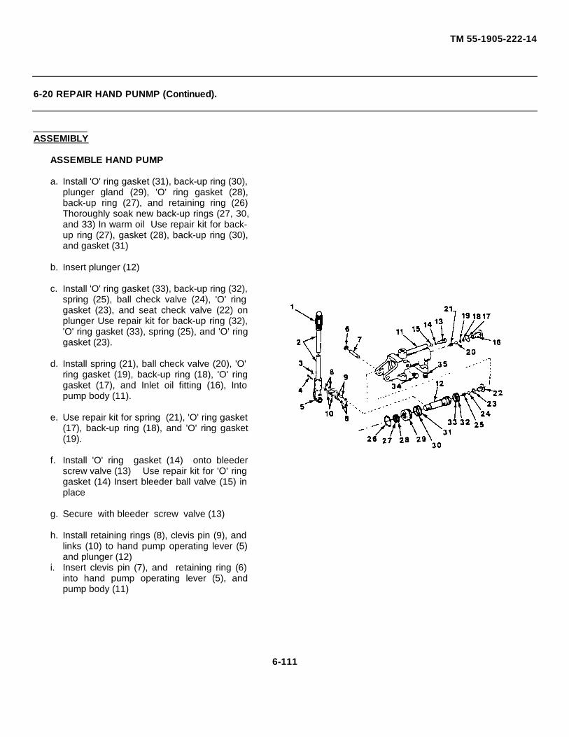
TM 55-1905-222-14
6-20 REPAIR HAND PUNMP (Continued).
ASSEMIBLY
ASSEMBLE HAND PUMP
a. Install 'O' ring gasket (31), back-up ring (30),plunger gland (29), 'O' ring gasket (28),back-up ring (27), and retaining ring (26)Thoroughly soak new back-up rings (27, 30,and 33) In warm oil Use repair kit for back-up ring (27), gasket (28), back-up ring (30),and gasket (31)
b. Insert plunger (12)
c. Install 'O' ring gasket (33), back-up ring (32),spring (25), ball check valve (24), 'O' ringgasket (23), and seat check valve (22) onplunger Use repair kit for back-up ring (32),'O' ring gasket (33), spring (25), and 'O' ringgasket (23).
d. Install spring (21), ball check valve (20), 'O'ring gasket (19), back-up ring (18), 'O' ringgasket (17), and Inlet oil fitting (16), Intopump body (11).
e. Use repair kit for spring (21), 'O' ring gasket(17), back-up ring (18), and 'O' ring gasket(19).
f. Install 'O' ring gasket (14) onto bleederscrew valve (13) Use repair kit for 'O' ringgasket (14) Insert bleeder ball valve (15) inplace
g. Secure with bleeder screw valve (13)
h. Install retaining rings (8), clevis pin (9), andlinks (10) to hand pump operating lever (5)and plunger (12)
i. Insert clevis pin (7), and retaining ring (6)into hand pump operating lever (5), andpump body (11)
6-111
TM 55-1905-222-14
6-20 REPAIR HAND PUMP (Continued).
j. Insert handle (2), pin (4), and cotterpin (3) into hand pump operating lever(5).
k. Install grip (1).
l. Install pipe plugs (34 and 35) ifremoved.
6-112
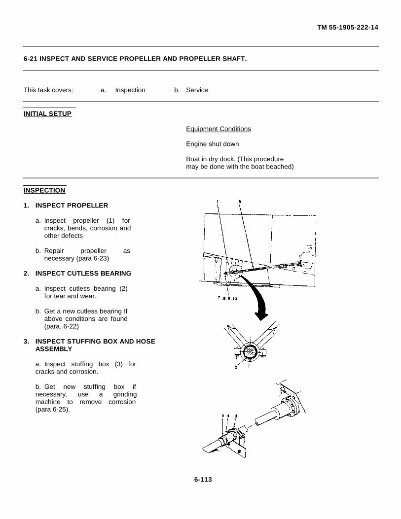
TM 55-1905-222-14
6-21 INSPECT AND SERVICE PROPELLER AND PROPELLER SHAFT.
This task covers: a. Inspection b. Service
INITIAL SETUP
Equipment Conditions
Engine shut down
Boat in dry dock. (This proceduremay be done with the boat beached)
INSPECTION
1. INSPECT PROPELLER
a. Inspect propeller (1) forcracks, bends, corrosion andother defects
b. Repair propeller asnecessary (para 6-23)
2. INSPECT CUTLESS BEARING
a. Inspect cutless bearing (2)for tear and wear.
b. Get a new cutless bearing Ifabove conditions are found(para. 6-22)
3. INSPECT STUFFING BOX AND HOSEASSEMBLY
a. Inspect stuffing box (3) forcracks and corrosion.
b. Get new stuffing box ifnecessary, use a grindingmachine to remove corrosion(para 6-25).
6-113
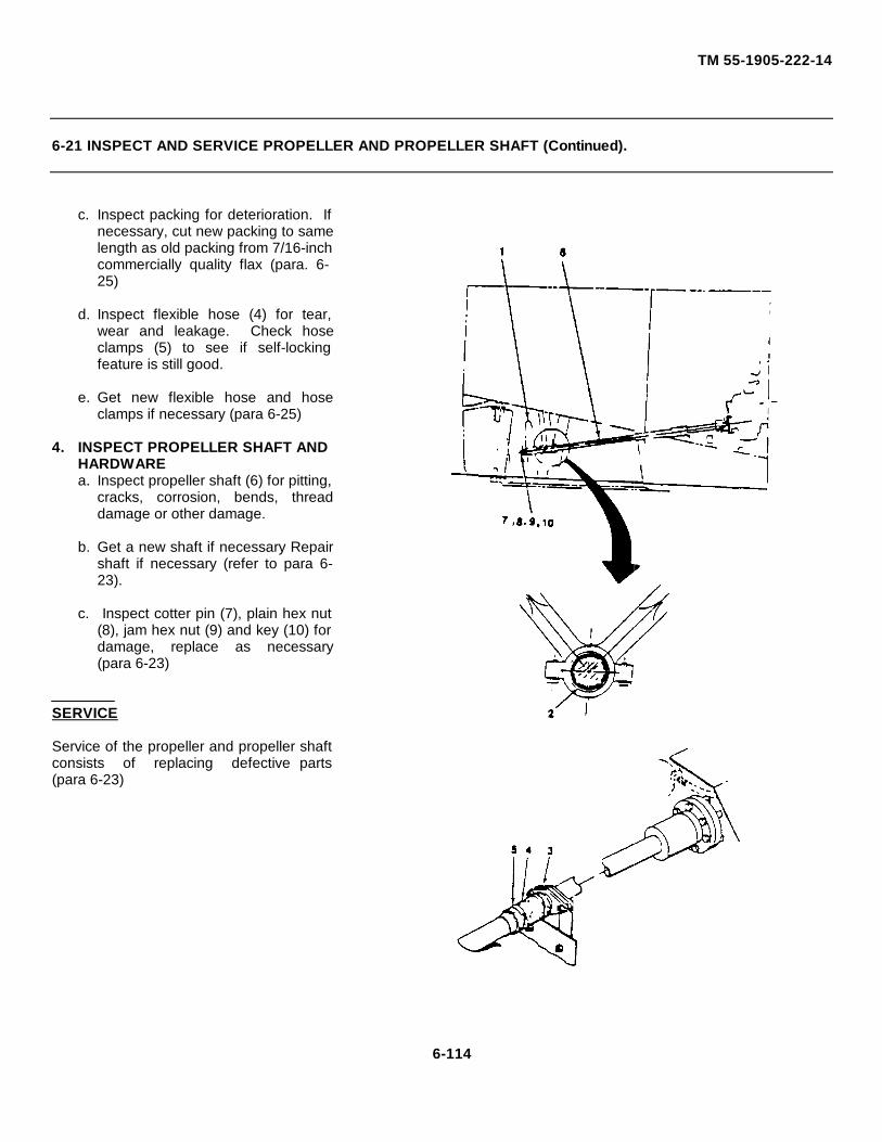
TM 55-1905-222-14
6-21 INSPECT AND SERVICE PROPELLER AND PROPELLER SHAFT (Continued).
c. Inspect packing for deterioration. Ifnecessary, cut new packing to samelength as old packing from 7/16-inchcommercially quality flax (para. 6-25)
d. Inspect flexible hose (4) for tear,wear and leakage. Check hoseclamps (5) to see if self-lockingfeature is still good.
e. Get new flexible hose and hoseclamps if necessary (para 6-25)
4. INSPECT PROPELLER SHAFT ANDHARDWAREa. Inspect propeller shaft (6) for pitting,
cracks, corrosion, bends, threaddamage or other damage.
b. Get a new shaft if necessary Repairshaft if necessary (refer to para 6-23).
c. Inspect cotter pin (7), plain hex nut(8), jam hex nut (9) and key (10) fordamage, replace as necessary(para 6-23)
SERVICE
Service of the propeller and propeller shaftconsists of replacing defective parts(para 6-23)
6-114

TM 55-1905-222-146-22 REPLACE PROPELLER AND PROPELLER SHAFT.
This task covers a. Removal b. Installation
INITIAL SETUP
Tools: Equipment Conditions:
Tool Kit, Mechanics Rail Engine shut down.and Marine5180-00-629-9783 Boat in dry dock (This
Propeller Puller procedure may be doneS00-372-0652 with the boat beached).
Wrench, Box, Propeller Nut5120-00-277-1575 Personnel:
Wrench, Box, Shaft5120-00-277-1576 Two (2)
Materials/Parts: General Safety Instructions:
Cutless Bearing (2 1/2 in ID x 3 s/8 In Do not attempt to removeOD x 10 in L-Brass/Rubber) propeller and shaft by
Cotter Pin yourself.MS 24665-641
Cotter PinMS 24665-519
WasherMS 15795-832
Flexible Hose4720-00-288-9761
Hose Clamps4730-00-197-1595
Packing7/16 in flax, Item 28, Appendix E
GraphiteItem 23, Appendix E
GreaseItem 22, Appendix E
6-115
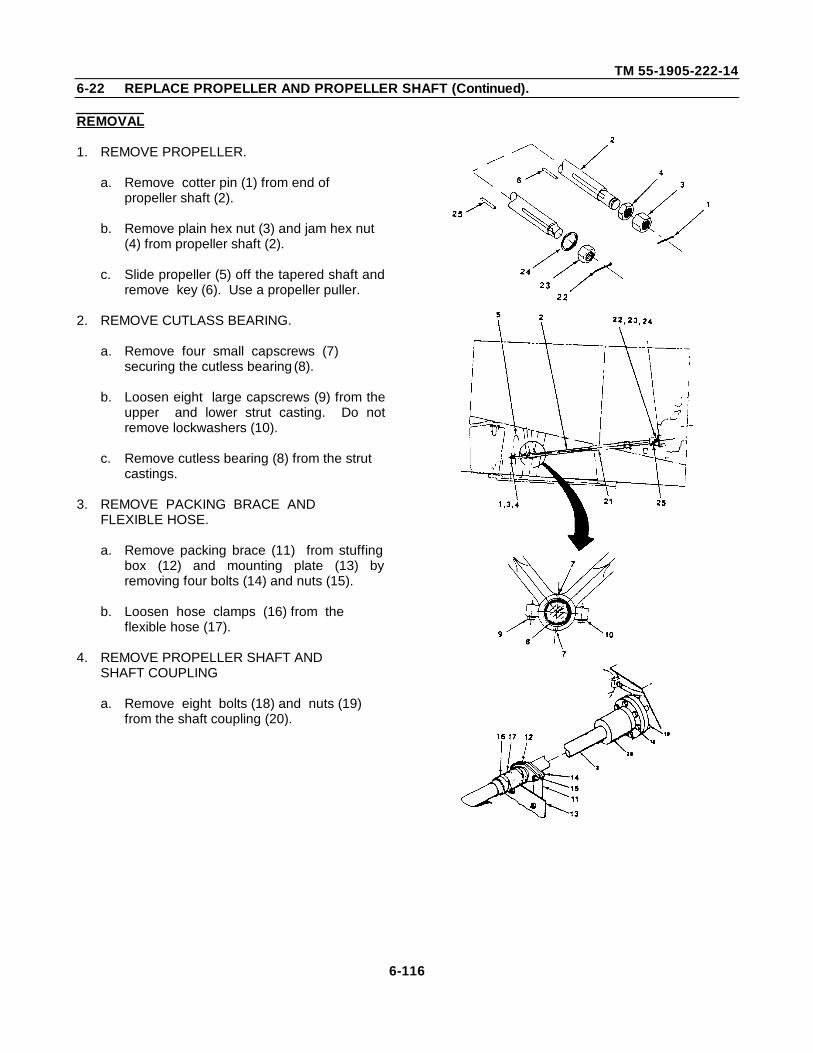
TM 55-1905-222-146-22 REPLACE PROPELLER AND PROPELLER SHAFT (Continued).
REMOVAL
1. REMOVE PROPELLER.
a. Remove cotter pin (1) from end of propeller shaft (2).
b. Remove plain hex nut (3) and jam hex nut (4) from propeller shaft (2).
c. Slide propeller (5) off the tapered shaft andremove key (6). Use a propeller puller.
2. REMOVE CUTLASS BEARING.
a. Remove four small capscrews (7) securing the cutless bearing (8).
b. Loosen eight large capscrews (9) from theupper and lower strut casting. Do notremove lockwashers (10).
c. Remove cutless bearing (8) from the strut castings.
3. REMOVE PACKING BRACE ANDFLEXIBLE HOSE.
a. Remove packing brace (11) from stuffingbox (12) and mounting plate (13) byremoving four bolts (14) and nuts (15).
b. Loosen hose clamps (16) from the flexible hose (17).
4. REMOVE PROPELLER SHAFT ANDSHAFT COUPLING
a. Remove eight bolts (18) and nuts (19) from the shaft coupling (20).
6-116
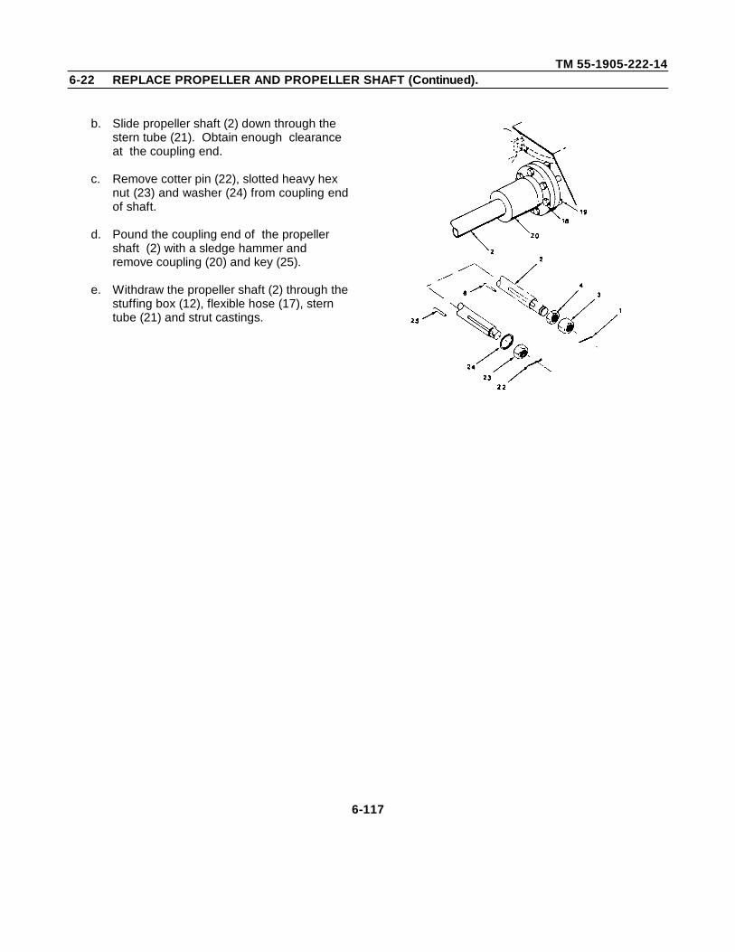
TM 55-1905-222-146-22 REPLACE PROPELLER AND PROPELLER SHAFT (Continued).
b. Slide propeller shaft (2) down through the stern tube (21). Obtain enough clearance at the coupling end.
c. Remove cotter pin (22), slotted heavy hex nut (23) and washer (24) from coupling endof shaft.
d. Pound the coupling end of the propeller shaft (2) with a sledge hammer and remove coupling (20) and key (25).
e. Withdraw the propeller shaft (2) through thestuffing box (12), flexible hose (17), stern tube (21) and strut castings.
6-117
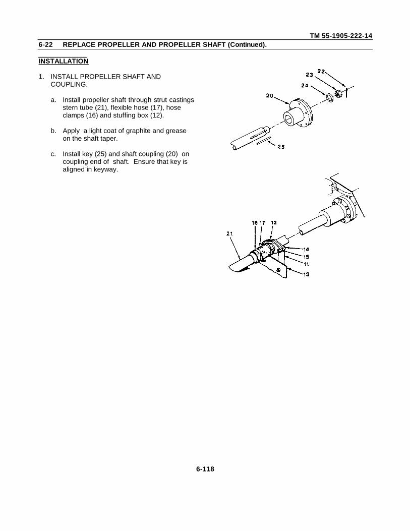
TM 55-1905-222-146-22 REPLACE PROPELLER AND PROPELLER SHAFT (Continued).
INSTALLATION
1. INSTALL PROPELLER SHAFT ANDCOUPLING.
a. Install propeller shaft through strut castingsstern tube (21), flexible hose (17), hose clamps (16) and stuffing box (12).
b. Apply a light coat of graphite and grease on the shaft taper.
c. Install key (25) and shaft coupling (20) on coupling end of shaft. Ensure that key is aligned in keyway.
6-118
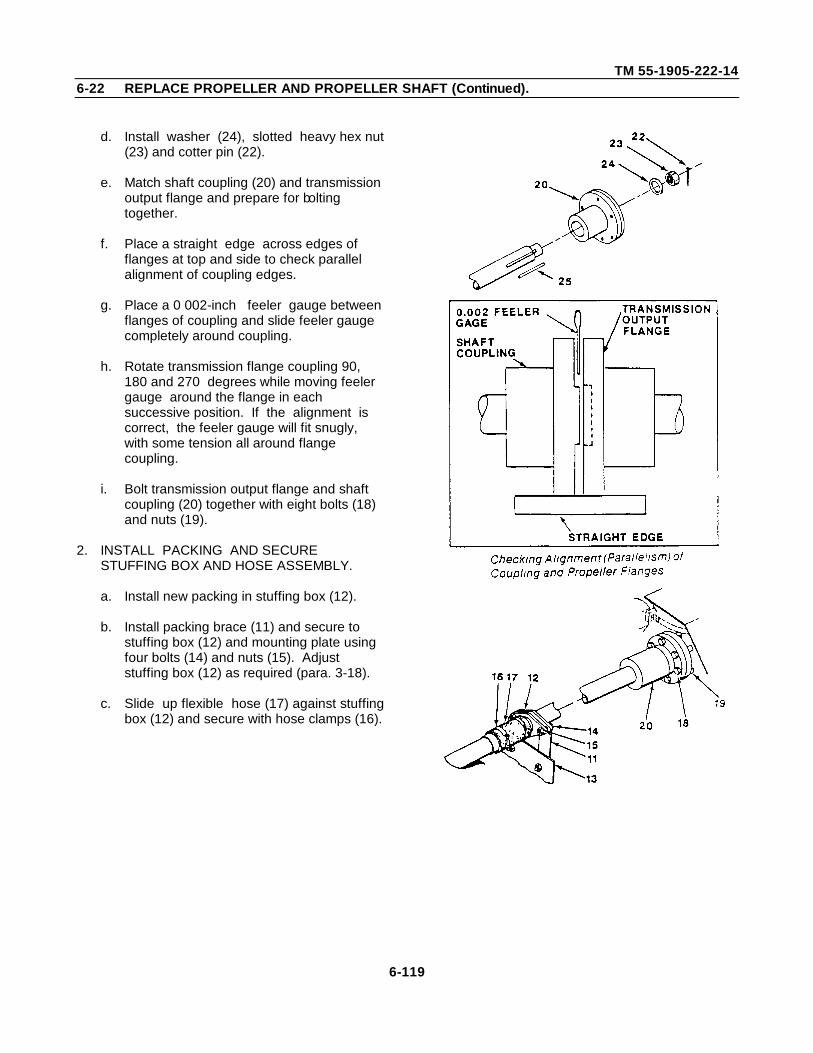
TM 55-1905-222-146-22 REPLACE PROPELLER AND PROPELLER SHAFT (Continued).
d. Install washer (24), slotted heavy hex nut(23) and cotter pin (22).
e. Match shaft coupling (20) and transmission output flange and prepare for bolting together.
f. Place a straight edge across edges of flanges at top and side to check parallel alignment of coupling edges.
g. Place a 0 002-inch feeler gauge between flanges of coupling and slide feeler gauge completely around coupling.
h. Rotate transmission flange coupling 90, 180 and 270 degrees while moving feeler gauge around the flange in each successive position. If the alignment is correct, the feeler gauge will fit snugly, with some tension all around flange coupling.
i. Bolt transmission output flange and shaft coupling (20) together with eight bolts (18) and nuts (19).
2. INSTALL PACKING AND SECURESTUFFING BOX AND HOSE ASSEMBLY.
a. Install new packing in stuffing box (12).
b. Install packing brace (11) and secure to stuffing box (12) and mounting plate using four bolts (14) and nuts (15). Adjust stuffing box (12) as required (para. 3-18).
c. Slide up flexible hose (17) against stuffingbox (12) and secure with hose clamps (16).
6-119
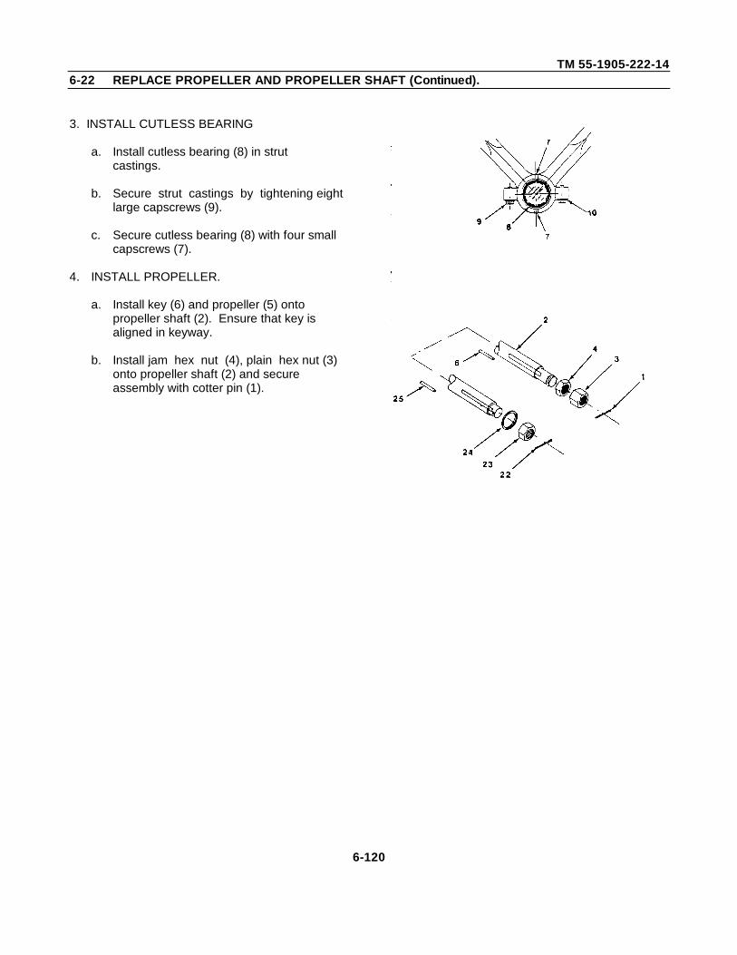
TM 55-1905-222-146-22 REPLACE PROPELLER AND PROPELLER SHAFT (Continued).
3. INSTALL CUTLESS BEARING
a. Install cutless bearing (8) in strut castings.
b. Secure strut castings by tightening eight large capscrews (9).
c. Secure cutless bearing (8) with four small capscrews (7).
4. INSTALL PROPELLER.
a. Install key (6) and propeller (5) onto propeller shaft (2). Ensure that key is aligned in keyway.
b. Install jam hex nut (4), plain hex nut (3) onto propeller shaft (2) and secure assembly with cotter pin (1).
6-120
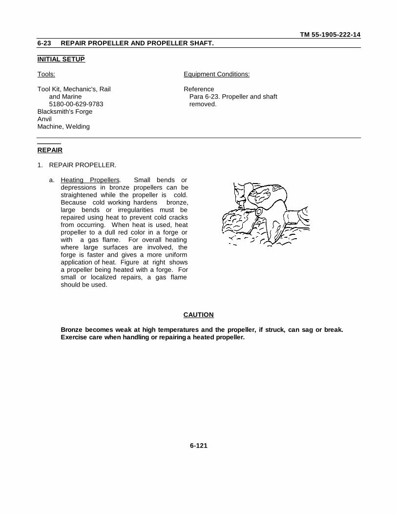
TM 55-1905-222-146-23 REPAIR PROPELLER AND PROPELLER SHAFT.
INITIAL SETUP
Tools: Equipment Conditions:
Tool Kit, Mechanic's, Rail Referenceand Marine Para 6-23. Propeller and shaft5180-00-629-9783 removed.
Blacksmith's ForgeAnvilMachine, Welding
REPAIR
1. REPAIR PROPELLER.
a. Heating Propellers. Small bends ordepressions in bronze propellers can bestraightened while the propeller is cold.Because cold working hardens bronze,large bends or irregularities must berepaired using heat to prevent cold cracksfrom occurring. When heat is used, heatpropeller to a dull red color in a forge orwith a gas flame. For overall heatingwhere large surfaces are involved, theforge is faster and gives a more uniformapplication of heat. Figure at right showsa propeller being heated with a forge. Forsmall or localized repairs, a gas flameshould be used.
CAUTION
Bronze becomes weak at high temperatures and the propeller, if struck, can sag or break.Exercise care when handling or repairing a heated propeller.
6-121
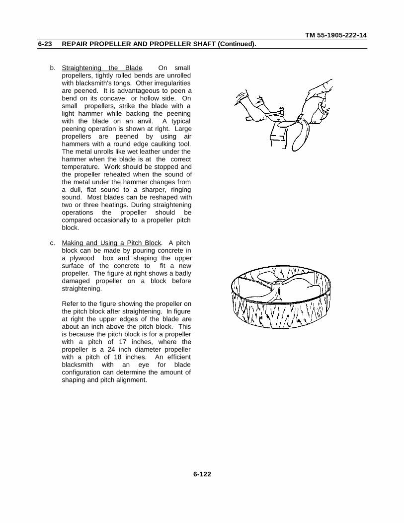
TM 55-1905-222-146-23 REPAIR PROPELLER AND PROPELLER SHAFT (Continued).
b. Straightening the Blade. On smallpropellers, tightly rolled bends are unrolledwith blacksmith's tongs. Other irregularitiesare peened. It is advantageous to peen abend on its concave or hollow side. Onsmall propellers, strike the blade with alight hammer while backing the peeningwith the blade on an anvil. A typicalpeening operation is shown at right. Largepropellers are peened by using airhammers with a round edge caulking tool.The metal unrolls like wet leather under thehammer when the blade is at the correcttemperature. Work should be stopped andthe propeller reheated when the sound ofthe metal under the hammer changes froma dull, flat sound to a sharper, ringingsound. Most blades can be reshaped withtwo or three heatings. During straighteningoperations the propeller should becompared occasionally to a propeller pitchblock.
c. Making and Using a Pitch Block. A pitchblock can be made by pouring concrete ina plywood box and shaping the uppersurface of the concrete to fit a newpropeller. The figure at right shows a badlydamaged propeller on a block beforestraightening.
Refer to the figure showing the propeller onthe pitch block after straightening. In figureat right the upper edges of the blade areabout an inch above the pitch block. Thisis because the pitch block is for a propellerwith a pitch of 17 inches, where thepropeller is a 24 inch diameter propellerwith a pitch of 18 inches. An efficientblacksmith with an eye for bladeconfiguration can determine the amount ofshaping and pitch alignment.
6-122
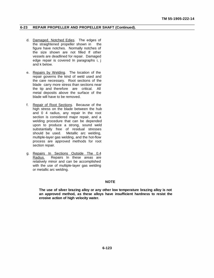
TM 55-1905-222-14
6-23 REPAIR PROPELLER AND PROPELLER SHAFT (Continued).
d. Damaged. Notched Edies. The edges ofthe straightened propeller shown in thefigure have notches. Normally notches ofthe size shown are not filled If othervessels are deadlined for repair. Damagededge repair is covered In paragraphs i, jand k below.
e. Repairs by Welding. The location of therepair governs the kind of weld used andthe care necessary. Root sections of theblade carry more stress than sections nearthe tip and therefore are critical. Allmetal deposits above the surface of theblade will have to be removed.
f. Repair of Root Sections. Because of thehigh stress on the blade between the huband 0 4 radius, any repair In the rootsection is considered major repair, and awelding procedure that can be dependedupon to produce a strong, sound weldsubstantially free of residual stressesshould be used. Metallic arc welding,multiple-layer gas welding, and the hot-flowprocess are approved methods for rootsection repair.
g. Repairs In Sections Outside The 0.4Radius. Repairs In these areas arerelatively minor and can be accomplishedwith the use of multiple-layer gas weldingor metallic arc welding.
NOTE
The use of silver brazing alloy or any other low temperature brazing alloy is notan approved method, as these alloys have insufficient hardness to resist theerosive action of high velocity water.
6-123
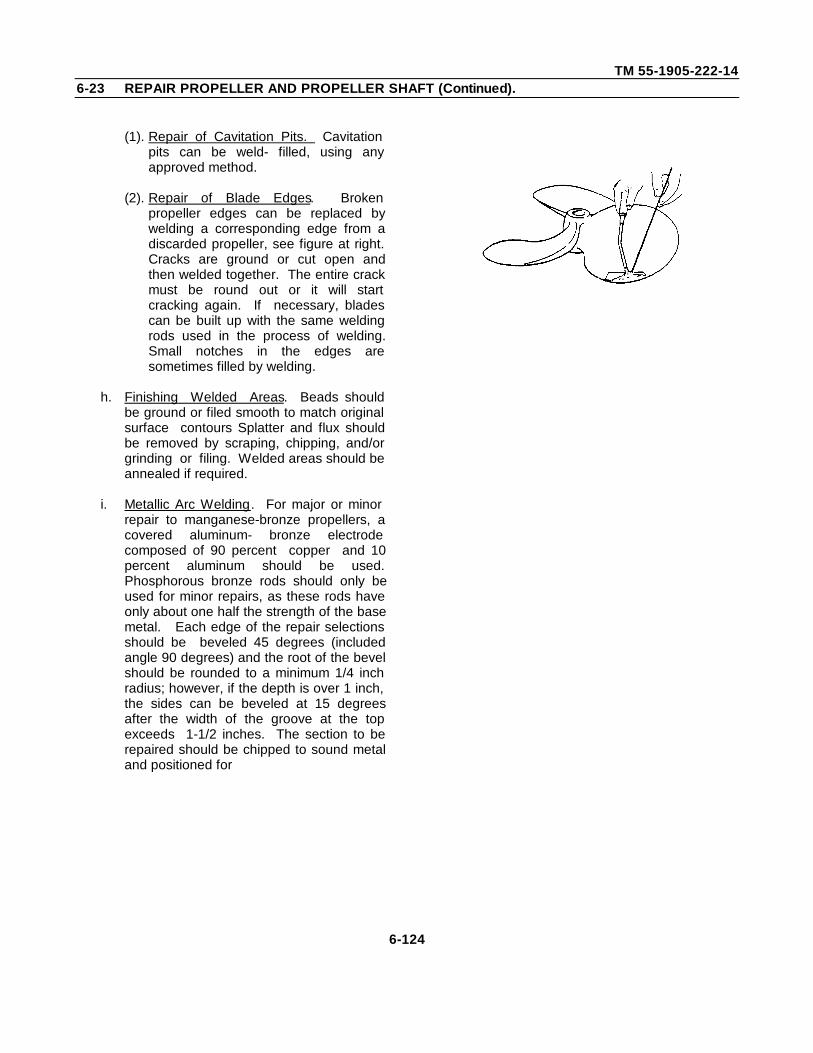
TM 55-1905-222-146-23 REPAIR PROPELLER AND PROPELLER SHAFT (Continued).
(1). Repair of Cavitation Pits. Cavitationpits can be weld- filled, using anyapproved method.
(2). Repair of Blade Edges. Brokenpropeller edges can be replaced bywelding a corresponding edge from adiscarded propeller, see figure at right.Cracks are ground or cut open andthen welded together. The entire crackmust be round out or it will startcracking again. If necessary, bladescan be built up with the same weldingrods used in the process of welding.Small notches in the edges aresometimes filled by welding.
h. Finishing Welded Areas. Beads shouldbe ground or filed smooth to match originalsurface contours Splatter and flux shouldbe removed by scraping, chipping, and/orgrinding or filing. Welded areas should beannealed if required.
i. Metallic Arc Welding. For major or minorrepair to manganese-bronze propellers, acovered aluminum- bronze electrodecomposed of 90 percent copper and 10percent aluminum should be used.Phosphorous bronze rods should only beused for minor repairs, as these rods haveonly about one half the strength of the basemetal. Each edge of the repair selectionsshould be beveled 45 degrees (includedangle 90 degrees) and the root of the bevelshould be rounded to a minimum 1/4 inchradius; however, if the depth is over 1 inch,the sides can be beveled at 15 degreesafter the width of the groove at the topexceeds 1-1/2 inches. The section to berepaired should be chipped to sound metaland positioned for
6-124
TM 55-1905-222-146-23 REPAIR PROPELLER AND PROPELLER SHAFT (Continued).
down-hand welding. Welds can be made Inthe vertical position, however, suitablecopper or carbon dams should be used toaid In supporting the weld metal In order toobtain a proper joint, it is imperative thatthe base metal be locally preheated. Thepreheat temperature should be between600F and 826F (316C and 427C).In an emergency, a temperature of 400F(204C) can be used. An approved rodof 1/4-, 5/16- or 3/8- inch diametershould be used, especially on propellersections over 3/8 inch thick. Smallerdiameters, 5/32 inch and 3/16 inch, shouldnot be used unless absolutely necessary,and then only when considerablepreheating has been done. Withsufficient preheat, lower values of thecurrent ranges recommended by theelectrode manufacturer can be used.Although lower currents are desirable, theoperator's skill and experience must beconsidered. Therefore, higher currents arepreferable to currents too low. Highercurrents risk fine porosity in the weld metal,but currents too low risk poor fusion andslag inclusions.
j. Hot-Flow Process. The hot-flow processprovides a satisfactory method for majorrepairs. This process consists of flowingmolten metal of approximately the samechemical composition as the base metalinto the joint. This flow washes awayand replaces the parent metal and forms acontinuous member upon solidification.Foundry and mold equipment is necessaryfor the use of this process.
6-125
TM 55-1905-222-146-23 REPAIR PROPELLER AND PROPELLER SHAFT (Continued).
k. Multiple-Layer Gas Welding. The multiple-layer gas welding method is an approvedfor major and minor repairs of propellers.The edges to be welded are beveled toform a 75 degree, single V-groove weldfor thicknesses less than 1-1/2 inches. A75 degree double V-groove is used if thethickness of the section is greater than 1-1/2 inches (381 cm) A copper-zinc, low-fuming, welding rod of the proper sizeand in accordance with MilitarySpecification MIL-R-19631 is used with asuitable brazing flux for repair ofmanganese-bronze propellers. A carefullyadjusted oxidizing flame is essential forsound welds. A forehand method ofwelding should be used and the weld metaldeposited in beads with limited oscillationnot exceeding 1-1/2 times the diameter ofthe welding rod.
l. Welding-Preheat and Stress ReliefBecause copper-zinc alloys are susceptibleto stress-corrosion or season cracking,stress must be relieved, as the propellercan crack after being returned to serviceThe use of local preheat above 400°F(204C), preferably between 600°F and800F (315C and 427C), will precludethe accumulation of harmful stresses. Hot-flow welds and large gas welds areautomatically preheated and slowly cooled,and stress relief can be safely omitted afterwelding. Arc welds and small gas weldsshould be preheated with a torch or othersuitable means and then cooled slowly.If it is considered more desirable to stressrelief after welding, the following procedureis recommended. Heat slowly to 750F(399C) and hold at this temperature for atleast 1 hour per Inch of thickness of metalIn the welded area, cool slowly,approximately 2F (1C), per minute,
6-126
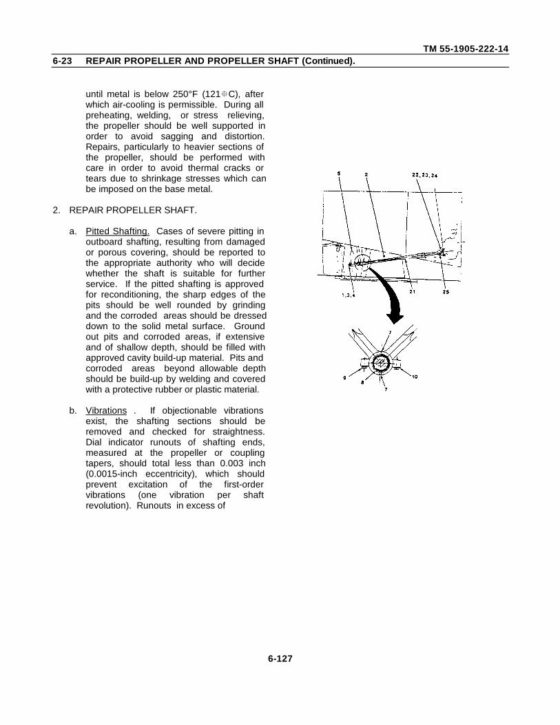
TM 55-1905-222-146-23 REPAIR PROPELLER AND PROPELLER SHAFT (Continued).
until metal is below 250°F (121C), afterwhich air-cooling is permissible. During allpreheating, welding, or stress relieving,the propeller should be well supported inorder to avoid sagging and distortion.Repairs, particularly to heavier sections ofthe propeller, should be performed withcare in order to avoid thermal cracks ortears due to shrinkage stresses which canbe imposed on the base metal.
2. REPAIR PROPELLER SHAFT.
a. Pitted Shafting. Cases of severe pitting inoutboard shafting, resulting from damagedor porous covering, should be reported tothe appropriate authority who will decidewhether the shaft is suitable for furtherservice. If the pitted shafting is approvedfor reconditioning, the sharp edges of thepits should be well rounded by grindingand the corroded areas should be dresseddown to the solid metal surface. Groundout pits and corroded areas, if extensiveand of shallow depth, should be filled withapproved cavity build-up material. Pits andcorroded areas beyond allowable depthshould be build-up by welding and coveredwith a protective rubber or plastic material.
b. Vibrations . If objectionable vibrationsexist, the shafting sections should beremoved and checked for straightness.Dial indicator runouts of shafting ends,measured at the propeller or couplingtapers, should total less than 0.003 inch(0.0015-inch eccentricity), which shouldprevent excitation of the first-ordervibrations (one vibration per shaftrevolution). Runouts in excess of
6-127
TM 55-1905-222-146-23 REPAIR PROPELLER AND PROPELLER SHAFT (Continued).
0.003 inch total, giving an unacceptableperformance, must be rectified or replacedby a new shaft section.
c. Bent Shafting. Approval by the appropriateauthority should be obtained prior tostraightening severely bent shafting.Repair to the shafting sections can be doneby the spot heating method, or electricinduction heating, after which the shaft isstraightened by mechanically controlledforces.
d. Cracks In Shafting. Cracks found inpropulsion shafting should be thoroughlyprobed to determine the depth and lengthof the cracks. If shafting is determined tobe repairable, weld crack by an approvedmethod.
e. Eccentricity. The dial indicator runout forany length of shafting, with respect to theaxis of rotation and exclusive of journalsand ends, should be limited to aneccentricity of approximately 0003 inch.If, when the shafting is rotated 360degrees, runouts greater than this figureare found, this eccentricity should bereduced to the lowest possible limit. Arecord should be kept of all installedshafting where eccentricities exceed 0 003inch. Shafting should be replaced ifobjectionable vibration is still present.
f. Electrolytic Action. Zinc protector collarson the shafting should be replaced asnecessary. Steel shafting that is exposedto sea water should be protected fromelectrolyte action by a rubber or plasticprotective covering when electrolyticaction occurs between the steel shaft andthe bronze bearing journal sleeve.
6-128
TM 55-1905-222-146-23 REPAIR PROPELLER AND PROPELLER SHAFT (Continued).
g. Plugging Shaft Ends. All shafting that isexposed to sea water and has been boredthroughout its entire length must have bothends plugged to prevent water fromseeping into the hollow shaft and into thevessel. One method Is by tapping the shaftbore with a tapered pipe thread in thismethod, a threaded plug is fitted andinstalled with thread compound to insurethe watertightness of the plug.
6-129
TM 55-1905-222-146-24 ALIGN PROPELLER AND PROPELLER SHAFT.
INITIAL SETUP
Tools: Equipment Conditions:
Tool Kit, Mechanics Rail LCM-8 out of water.and Marine LCM-8 water-borne.5180-00-629-9783
Dial Indicator
Materials/Parts:
Piano WireItem 27, Appendix E
ALIGNMENT
ALIGN PROPELLER SHAFT.
a. Alignment of shaft and bearings is notpermanently fixed. The alignment changeswith every docking due to changes in thekeel blocking, temperature variations, andthe direction of the sun's rays relative to thefore and aft line of the vessel. Thealignment of shafting and bearings isaffected by the temporary removal ofmachinery attached to the shafting or in thevicinity of the shafting because of theredistribution of weights and stresses. Thealignment is not the same when the vesselis waterborne as when it is in drydock. Thefinal alignment and bolting of the mainpropulsion shafting should always be donewhen the vessel is waterborne.
b. The primary purpose for providing correctalignment is to eliminate shaft excitedvibrations and to prevent an excessivepressure upon any localized portion of theshafting bearing surfaces (journal bearingareas). The longitudinal line connectingthe lowest extremities of all shaftingjournals having the same diameter shouldform a continuous-faired line when themachinery is at
6-130
TM 55-1905-222-146-24 ALIGN PROPELLER AND PROPELLER SHAFT (Continued).
operating temperature. When the shafting iscorrectly aligned.
At rest, the bottoms of the shaft journals shouldbe in contact with the bearing material. Thebearing clearance at the horizontal centerline ofthe journal should be equally divided.
c. In order to obtain and maintain acceptablealignment, the fundamentals of long-established and good practice are asfollows:
(1) Each bearing shall guide and supportthe proportionate share of the shaftingweight and load.
(2) When shaft couplings are broken, eachoverhanging shaft length will deflectfrom the true shaft centerline,depending upon the amount of over-hanging shaft weight, the loading andthe location of the bearing supports.
(3) Alignment of sag charts have beenprepared for most vessels showingrelative flange positions and theangular slopes of shafting with thecoupling bolts have been removed.With tie bearings adjusted to obtainthese measurements, proper alignmentof the shafting is insured when thecoupling bolts are secures.
d. Methods of Determining Alignment.
(1) The proper location of the bearings onmain propulsion shafting may bechecked by running a line wire. Thisconsists of rigging supports
6-131
TM 55-1905-222-146-24 ALIGN PROPELLER AND PROPELLER SHAFT (Continued).
just clear of the end of the outerbearings of the set to be aligned. Alength of piano wire is stretchedbetween the supports. The supportsmust be rigid and not subject todeflection when the wire is put undertension. The wire should be attachedto the supports. In such a way that itcan be accurately centered in the endbearings. After the wire has beencentered in the end bearings, the wireforms the line of reference (whencorrected for sag) for all the interveningbearings.
(2) Alignment of shafting by the opticalmethod makes use of the line of sight,which for all practical purposes is atrue line. This method consists ofboring a large hole in the end of twoboards. One board is fitted at each endbearing of the set to be aligned. Asmall hole (about 1/16 to 1/8 inch) isdrilled in two pieces of thin sheet metal.The sheet metal is placed on theboards and the small holes areadjusted so that they are aligned withthe center of the end bearings. A lightis placed behind the board on one endand observed through the hole in theboard at the other end. Theintermediate boards are adjusted sothat the light can be seen through allthe holes. The center of these holesserves to establish the reference line.
(3) When it is suspected that the shaft isout of alignment, it should be checkedby slacking the coupling bolts at acoupling.
6-132
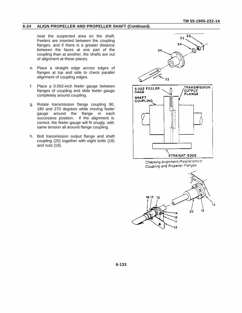
TM 55-1905-222-146-24 ALIGN PROPELLER AND PROPELLER SHAFT (Continued).
near the suspected area on the shaft.Feelers are inserted between the couplingflanges, and if there is a greater distancebetween the faces at one part of thecoupling than at another, the shafts are outof alignment at these places.
e. Place a straight edge across edges offlanges at top and side to check parallelalignment of coupling edges.
f. Place a 0.002-inch feeler gauge betweenflanges of coupling and slide feeler gaugecompletely around coupling.
g. Rotate transmission flange coupling 90,180 and 270 degrees while moving feelergauge around the flange in eachsuccessive position. If the alignment iscorrect, the feeler gauge will fit snugly, withsame tension all around flange coupling.
h. Bolt transmission output flange and shaftcoupling (20) together with eight bolts (18)and nuts (19).
6-133
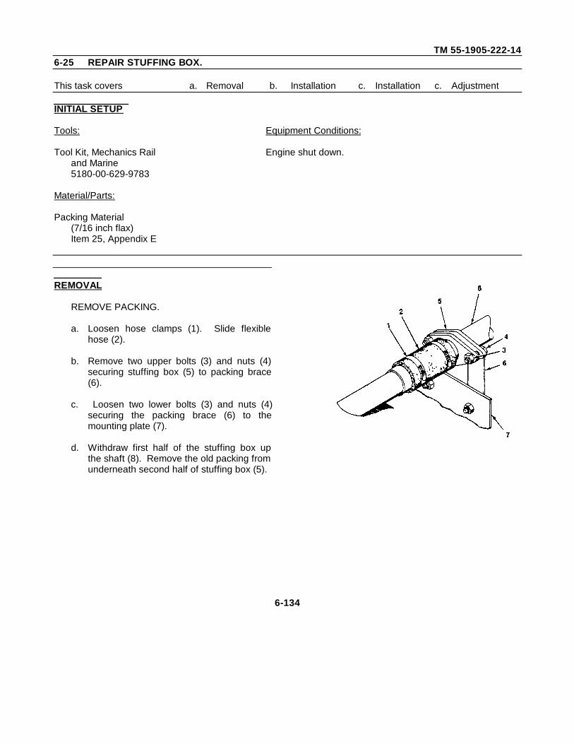
TM 55-1905-222-146-25 REPAIR STUFFING BOX.
This task covers a. Removal b. Installation c. Installation c. Adjustment
INITIAL SETUP
Tools: Equipment Conditions:
Tool Kit, Mechanics Rail Engine shut down.and Marine5180-00-629-9783
Material/Parts:
Packing Material(7/16 inch flax)Item 25, Appendix E
REMOVAL
REMOVE PACKING.
a. Loosen hose clamps (1). Slide flexiblehose (2).
b. Remove two upper bolts (3) and nuts (4)securing stuffing box (5) to packing brace(6).
c. Loosen two lower bolts (3) and nuts (4)securing the packing brace (6) to themounting plate (7).
d. Withdraw first half of the stuffing box upthe shaft (8). Remove the old packing fromunderneath second half of stuffing box (5).
6-134
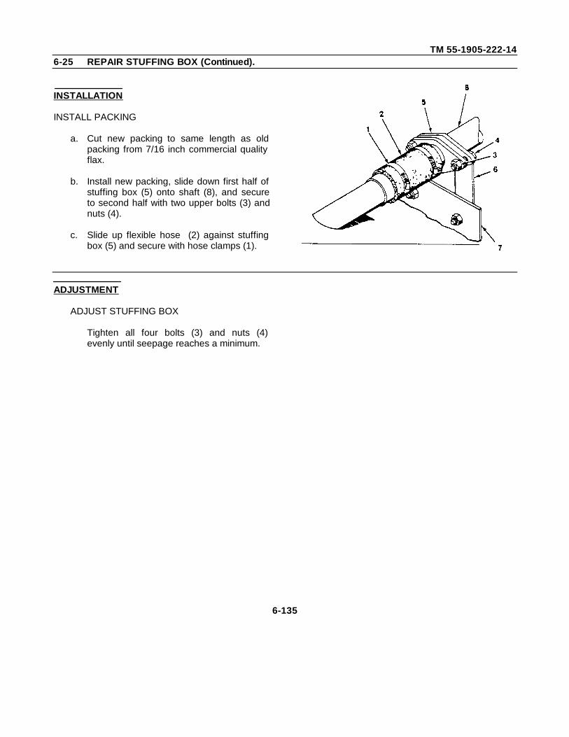
TM 55-1905-222-146-25 REPAIR STUFFING BOX (Continued).
INSTALLATION
INSTALL PACKING
a. Cut new packing to same length as oldpacking from 7/16 inch commercial qualityflax.
b. Install new packing, slide down first half ofstuffing box (5) onto shaft (8), and secureto second half with two upper bolts (3) andnuts (4).
c. Slide up flexible hose (2) against stuffingbox (5) and secure with hose clamps (1).
ADJUSTMENT
ADJUST STUFFING BOX
Tighten all four bolts (3) and nuts (4)evenly until seepage reaches a minimum.
6-135
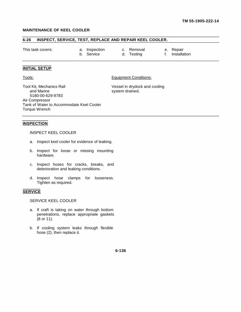
TM 55-1905-222-14
MAINTENANCE OF KEEL COOLER
6-26 INSPECT, SERVICE, TEST, REPLACE AND REPAIR KEEL COOLER.
This task covers: a. Inspection c. Removal e. Repairb. Service d. Testing f. Installation
INITIAL SETUP
Tools: Equipment Conditions:
Tool Kit, Mechanics Rail Vessel in drydock and coolingand Marine system drained.5180-00-629-9783
Air CompressorTank of Water to Accommodate Keel CoolerTorque Wrench
INSPECTION
INSPECT KEEL COOLER
a. Inspect keel cooler for evidence of leaking.
b. Inspect for loose or missing mountinghardware.
c. Inspect hoses for cracks, breaks, anddeterioration and leaking conditions.
d. Inspect hose clamps for looseness.Tighten as required.
SERVICE
SERVICE KEEL COOLER
a. If craft is taking on water through bottompenetrations, replace appropriate gaskets(8 or 11).
b. If cooling system leaks through flexiblehose (2), then replace it.
6-136
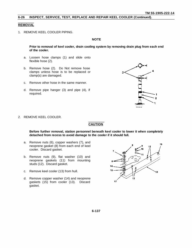
TM 55-1905-222-146-26 INSPECT, SERVICE, TEST, REPLACE AND REPAIR KEEL COOLER (Continued).
REMOVAL
1. REMOVE KEEL COOLER PIPING.
NOTE
Prior to removal of keel cooler, drain cooling system by removing drain plug from each endof the cooler.
a. Loosen hose clamps (1) and slide ontoflexible hose (2).
b. Remove hose (2). Do Not remove hoseclamps unless hose is to be replaced orclamp(s) are damaged.
c. Remove other hose in the same manner.
d. Remove pipe hanger (3) and pipe (4), ifrequired.
2. REMOVE KEEL COOLER.
CAUTION
Before further removal, station personnel beneath keel cooler to lower it when completelydetached from recess to avoid damage to the cooler if it should fall.
a. Remove nuts (6), copper washers (7), andneoprene gasket (8) from each end of keelcooler. Discard gasket.
b. Remove nuts (9), flat washer (10) andneoprene gaskets (11) from mountingstuds (12). Discard gasket.
c. Remove keel cooler (13) from hull.
d. Remove copper washer (14) and neoprenegaskets (15) from cooler (13). Discardgasket.
6-137
TM 55-1905-222-146-26 INSPECT, SERVICE, TEST, REPLACE AND REPAIR KEEL COOLER (Continued).
TESTING
TEST KEEL COOLER
a. Provide seal for one inlet to hold air underpressure (approximately 20 psi [137 8 kPa]).
b. Prepare fitting for second inlet that has air linefitting.
c. Install both Inlet fittings
d. Pressurize cooler to approximately 10 psi(68.9 kPa) and submerge cooler in clear waternot allowing "seals" to be submerged.
e. Observe any air bubble that would indicate aleak.
f. If a leak is found, cooler must be replaced.
REPAIR
REPAIR KEEL COOLER
a. Replace keel cooler if leak(s) were found orkeel cooler is damaged beyond repair.
b. Replace all gaskets.
c. Replace all damaged or defective hardware.
d. Replace defective hoses or hose clamps.
e. Replace defective piping.
6-138
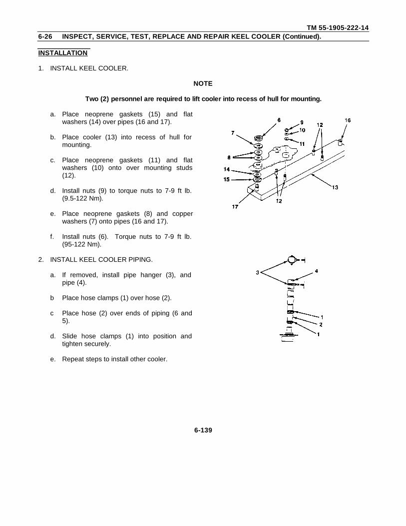
TM 55-1905-222-146-26 INSPECT, SERVICE, TEST, REPLACE AND REPAIR KEEL COOLER (Continued).
INSTALLATION
1. INSTALL KEEL COOLER.
NOTE
Two (2) personnel are required to lift cooler into recess of hull for mounting.
a. Place neoprene gaskets (15) and flatwashers (14) over pipes (16 and 17).
b. Place cooler (13) into recess of hull formounting.
c. Place neoprene gaskets (11) and flatwashers (10) onto over mounting studs(12).
d. Install nuts (9) to torque nuts to 7-9 ft lb.(9.5-122 Nm).
e. Place neoprene gaskets (8) and copperwashers (7) onto pipes (16 and 17).
f. Install nuts (6). Torque nuts to 7-9 ft lb.(95-122 Nm).
2. INSTALL KEEL COOLER PIPING.
a. If removed, install pipe hanger (3), andpipe (4).
b Place hose clamps (1) over hose (2).
c Place hose (2) over ends of piping (6 and5).
d. Slide hose clamps (1) into position andtighten securely.
e. Repeat steps to install other cooler.
6-139
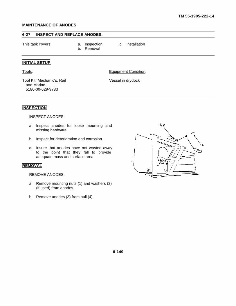
TM 55-1905-222-14
MAINTENANCE OF ANODES
6-27 INSPECT AND REPLACE ANODES.
This task covers: a. Inspection c. Installationb. Removal
INITIAL SETUP
Tools: Equipment Condition:
Tool Kit, Mechanic's, Rail Vessel in drydockand Marine5180-00-629-9783
INSPECTION
INSPECT ANODES.
a. Inspect anodes for loose mounting andmissing hardware.
b. Inspect for deterioration and corrosion.
c. Insure that anodes have not wasted awayto the point that they fall to provideadequate mass and surface area.
REMOVAL
REMOVE ANODES.
a. Remove mounting nuts (1) and washers (2)(if used) from anodes.
b. Remove anodes (3) from hull (4).
6-140
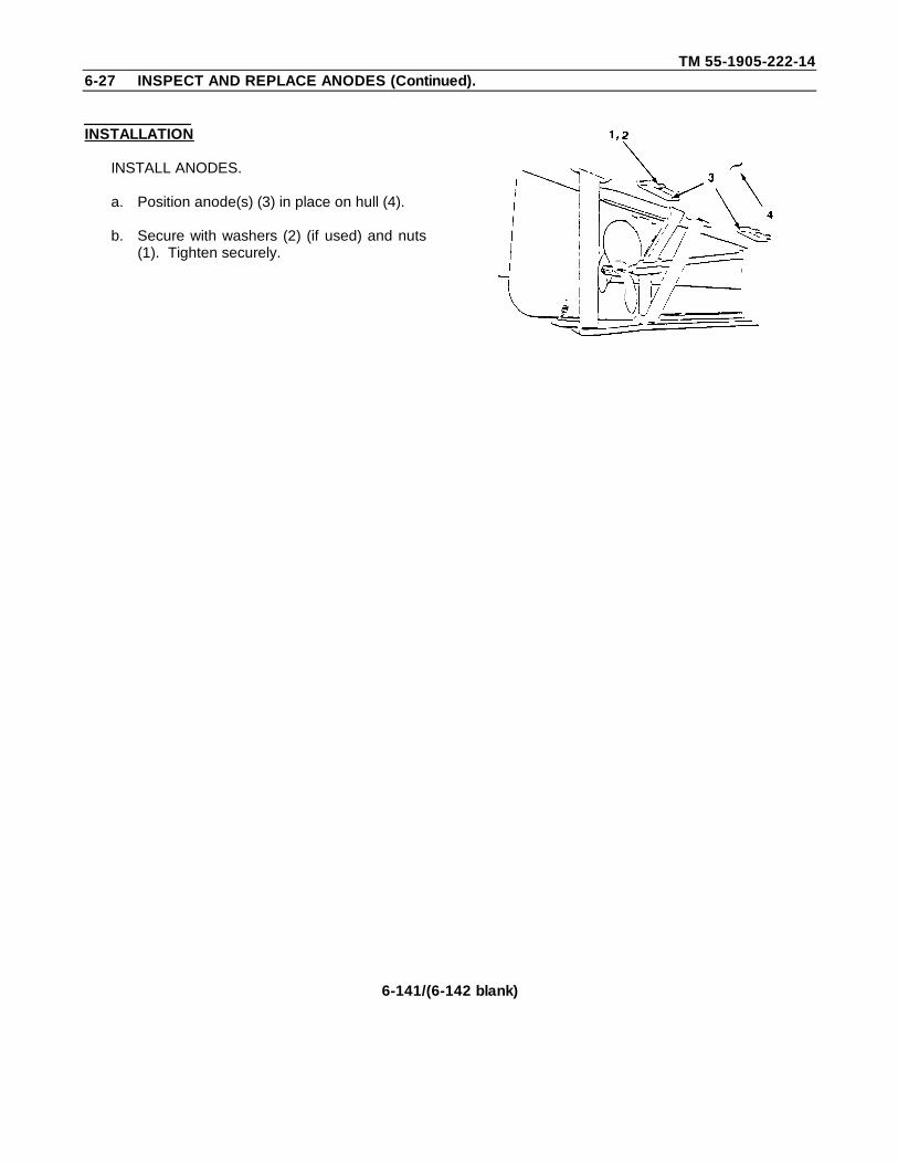
TM 55-1905-222-146-27 INSPECT AND REPLACE ANODES (Continued).
INSTALLATION
INSTALL ANODES.
a. Position anode(s) (3) in place on hull (4).
b. Secure with washers (2) (if used) and nuts(1). Tighten securely.
6-141/(6-142 blank)
TM55-1905-222-14
APPENDIX A
REFERENCES
A-1 SCOPE. This appendix lists all publications, manuals, directives and forms used in this technicalmanual, including reference material furnished by the Government.
A-2 ARMY REGULATIONS.
AR 55-19 Marine CasualtiesAR 56-9 Watercraft
A-3 DEPARTMENT OF THE ARMY PAMPHLET.
DA PAM 738-750 The Army Maintenance Management System (TAMMS)
A-4 FIELD MANUALS.
FM55-50 Army Water Transport OperationsFM55-501 Marine Crewman's HandbookFM55-501-1 Landing Craft Operator's HandbookFM55-506-2 Marine Engineman's Electrical Handbook
A-5 FORMS.
DA FORM 285 US Army Accident Investigation ReportDA FORM 2028 Recommended Changes to DA PublicationsDA FORM 2404 Equipment Inspection and Maintenance WorksheetDA FORM 2407 Maintenance RequestDA FORM 4640 Harbor Boat Deck Department Log for Class A and B VesselsDA FORM 4993 Harbor Boat Engine Department Log for Class A and C-1
VesselsRCS CSGLD-13 14 Report of Marine CasualtySF 368 Quality Deficiency ReportUSCG FORM CG 4602 Oil Record Book for Non-Tankers
A-1
TM55-1905-222-14
A-6 LUBRICATION ORDERS.
LO 55-1905-222-12 Landing Craft, Mechanized (LCM-8) (Rohr and Gunderson Models)(1905-01-284-2647 and 1905-01-284-2648).
A-7 TECHNICAL BULLETINS.
TB 54200-200-10 Hand Portable Fire Extinguishers Approved for Army Users
TB 43-0117 Watercraft Electronics Configuration Directory
TB 43-0144 Painting of Vessels
TB 55-1900-201-45/1 Guide to Army Watercraft Survey Inspections, Repair Procedures andRepair Specifications Preparation
TB 55-1900-202-12/1 US Army Mobility Equipment Center Floating Craft PreventiveMaintenance
TB 55-1900-202-12/2 Time Between Overhauls for All Marine Engines
TB 55-1900-204-24 Arc Welding on Water-Borne Vessels
TB 55-1900-205-24 Watercraft Information and Reporting System
TB 55-1900-206-14 Control and Abatement of Pollution by Army Watercraft
TB 55-1900-207-24 Treatment of Cooling Water m Marine Diesel Engines
TB 55-6605-262-24 Calibration, General Support Maintenance and Troubleshooting forRemote Magnetic Heading System (RMHS) Magnetic Compass,Mk 27, MOD 0 and MOD 1 Gyrocompass System.
TB 750-651 Use of Antifreeze Solutions and Cleaning Compounds in EngineCooling System
TB 740-97-2 Preservation of USAMECOM Mechanical Equipment for Shipment andStorage
TB 740-97-4 Preservation of Vessels for Storage
Change 4 A-2
TM 55-1905-222-14
A-8 TECHNICAL MANUALS.
TM55-2090-201-14&P Operator, Organizational, Direct andGeneral Support Maintenance Manual (In-cluding Repair Parts and Special ToolsList) 5GPM Oil/Water Separator
TM9-6140-200-14 Operator, Organizational, Direct andGeneral Support Maintenance Manual forLead-Acid Storage Batteries
TM11-5820-401-12 Operator and Organizational MaintenanceManual (Including Repair Parts andSpecial Tools List) Radio Set AN/VRC-46and AN/VRC-47
TM11-5820-401-34-2 Direct Support and General SupportMaintenance Manual Radio Sets AN/VRC-46 and AN/VRC-47
TM11-5820-401-34-3 Direct Support and General SupportMaintenance Manual Radio Sets AN/VRC-46 and AN/VRC-47
TM11-5820-401-ESC-2 Equipment Serviceability Criteria forRadio Set AN/VRC-46
TM11-5820-401-ESC-4 Equipment Serviceability Criteria forRadio Set AN/VRC-47
TM 11-5820-820-12 Operator and Organizational MaintenanceManual (Including Repair Parts andSpecial Tools List) Radio Sets AN/VRC-80 (V) 1 and AN/VRC-80 (V) 3
TM11-5820-820-30 Direct Support Maintenance Manual RadioSet AN/VRC-80 (V) 1/3
TM11-5915-224-14 Operator, Organizational, Direct andGeneral Support Maintenance ManualSuppressor, Electrical Transient MX-
7778A/GRC
TM11-5915-224-24P. Organizational, Direct Support and GeneralSupport Repair Parts and Special ToolsList (Including Depot Maintenance RepairParts And Special Tools)- Suppressor,Electrical Transient, MX9778/GRC
TM55-1905-222-24P Operator, Unit and Intermediate (Directand General Support) Repair Parts andSpecial Tools List for Landing Craft,Mechanized (Rohr and Gunderson Models)
A-3
TM 55-1905-222-14
TM 5-2815-231-14 Operator, Unit and Intermediate (Direct andGeneral Support) Maintenance Manual forEngine, Diesel, V-12 (Rohr and GundersonModels)
TM 5-2815-231-24P Operator, Unit and Intermediate (Direct andGeneral Support) Repair Parts and SpecialTools List for Engine, Diesel, V-12 (Rohrand Gunderson Models)
TM 740-97-4 Preservation of Vessels for Storage
TM 750-244-3 Procedures for Destruction of Equipment ToPrevent Enemy Use
TM 55-500 Marine Equipment Characteristics and Data
TM 55-503 Marine Salvage and Hull Repair
TM 9-237 Welding
A-4
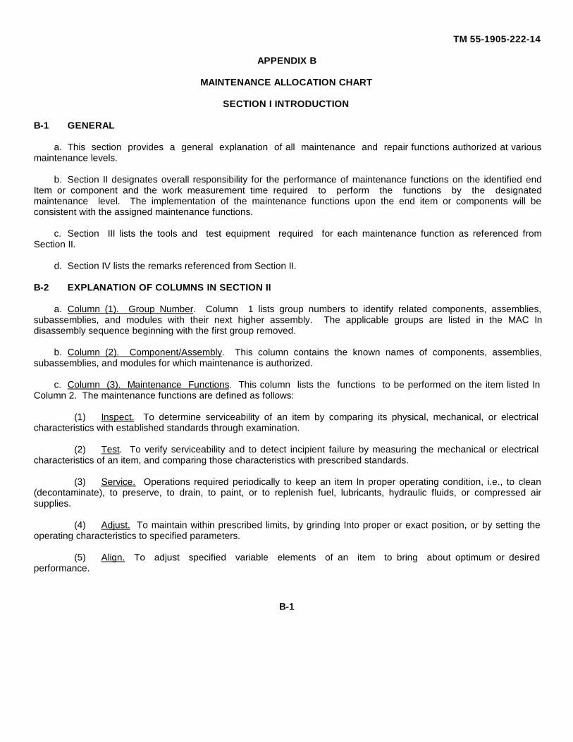
TM 55-1905-222-14
APPENDIX B
MAINTENANCE ALLOCATION CHART
SECTION I INTRODUCTION
B-1 GENERAL
a. This section provides a general explanation of all maintenance and repair functions authorized at variousmaintenance levels.
b. Section II designates overall responsibility for the performance of maintenance functions on the identified endItem or component and the work measurement time required to perform the functions by the designatedmaintenance level. The implementation of the maintenance functions upon the end item or components will beconsistent with the assigned maintenance functions.
c. Section III lists the tools and test equipment required for each maintenance function as referenced fromSection II.
d. Section IV lists the remarks referenced from Section II.
B-2 EXPLANATION OF COLUMNS IN SECTION II
a. Column (1). Group Number. Column 1 lists group numbers to identify related components, assemblies,subassemblies, and modules with their next higher assembly. The applicable groups are listed in the MAC Indisassembly sequence beginning with the first group removed.
b. Column (2). Component/Assembly. This column contains the known names of components, assemblies,subassemblies, and modules for which maintenance is authorized.
c. Column (3). Maintenance Functions. This column lists the functions to be performed on the item listed InColumn 2. The maintenance functions are defined as follows:
(1) Inspect. To determine serviceability of an item by comparing its physical, mechanical, or electricalcharacteristics with established standards through examination.
(2) Test. To verify serviceability and to detect incipient failure by measuring the mechanical or electricalcharacteristics of an item, and comparing those characteristics with prescribed standards.
(3) Service. Operations required periodically to keep an item In proper operating condition, i.e., to clean(decontaminate), to preserve, to drain, to paint, or to replenish fuel, lubricants, hydraulic fluids, or compressed airsupplies.
(4) Adjust. To maintain within prescribed limits, by grinding Into proper or exact position, or by setting theoperating characteristics to specified parameters.
(5) Align. To adjust specified variable elements of an item to bring about optimum or desiredperformance.
B-1
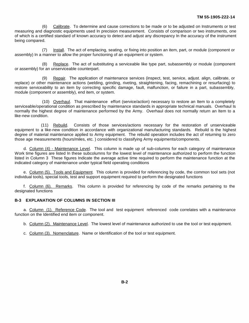
TM 55-1905-222-14
(6) Calibrate. To determine and cause corrections to be made or to be adjusted on Instruments or testmeasuring and diagnostic equipments used In precision measurement. Consists of comparison or two instruments, oneof which is a certified standard of known accuracy to detect and adjust any discrepancy In the accuracy of the instrumentbeing compared.
(7) Install. The act of emplacing, seating, or fixing into position an item, part, or module (component orassembly) In a manner to allow the proper functioning of an equipment or system.
(8) Replace. The act of substituting a serviceable like type part, subassembly or module (componentor assembly) for an unserviceable counterpart.
(9) Repair. The application of maintenance services (inspect, test, service, adjust. align, calibrate, orreplace) or other maintenance actions (welding, grinding, riveting, straightening, facing, remachining or resurfacing) torestore serviceability to an item by correcting specific damage, fault, malfunction, or failure in a part, subassembly,module (component or assembly), end item, or system.
(10) Overhaul. That maintenance effort (service/action) necessary to restore an Item to a completelyserviceable/operational condition as prescribed by maintenance standards in appropriate technical manuals. Overhaul Isnormally the highest degree of maintenance performed by the Army. Overhaul does not normally return an Item to alike-new condition.
(11) Rebuild. Consists of those services/actions necessary for the restoration of unserviceableequipment to a like-new condition in accordance with organizational manufacturing standards. Rebuild is the highestdegree of material maintenance applied to Army equipment. The rebuild operation includes the act of returning to zerothose age measurements (hours/miles, etc. ) considered to classifying Army equipments/components.
d. Column (4) - Maintenance Level. This column is made up of sub-columns for each category of maintenanceWork time figures are listed In these subcolumns for the lowest level of maintenance authorized to perform the functionlisted in Column 3 These figures Indicate the average active time required to perform the maintenance function at theindicated category of maintenance under typical field operating conditions
e. Column (5). Tools and Equipment. This column is provided for referencing by code, the common tool sets (notindividual tools), special tools, test and support equipment required to perform the designated functions
f. Column (6). Remarks. This column is provided for referencing by code of the remarks pertaining to thedesignated functions
B-3 EXPLANATION OF COLUMNS IN SECTION III
a. Column (1). Reference Code. The tool and test equipment referenced code correlates with a maintenancefunction on the Identified end item or component.
b. Column (2). Maintenance Level. The lowest level of maintenance authorized to use the tool or test equipment.
c. Column (3). Nomenclature. Name or Identification of the tool or test equipment.
B-2

TM 55-1905-222-14
d. Column (4). National/NATO Stock Number. The National or NATO stock number of the tool or test equipment.
e. Column (5). Tool Number. The manufacturer's part number.
B-3
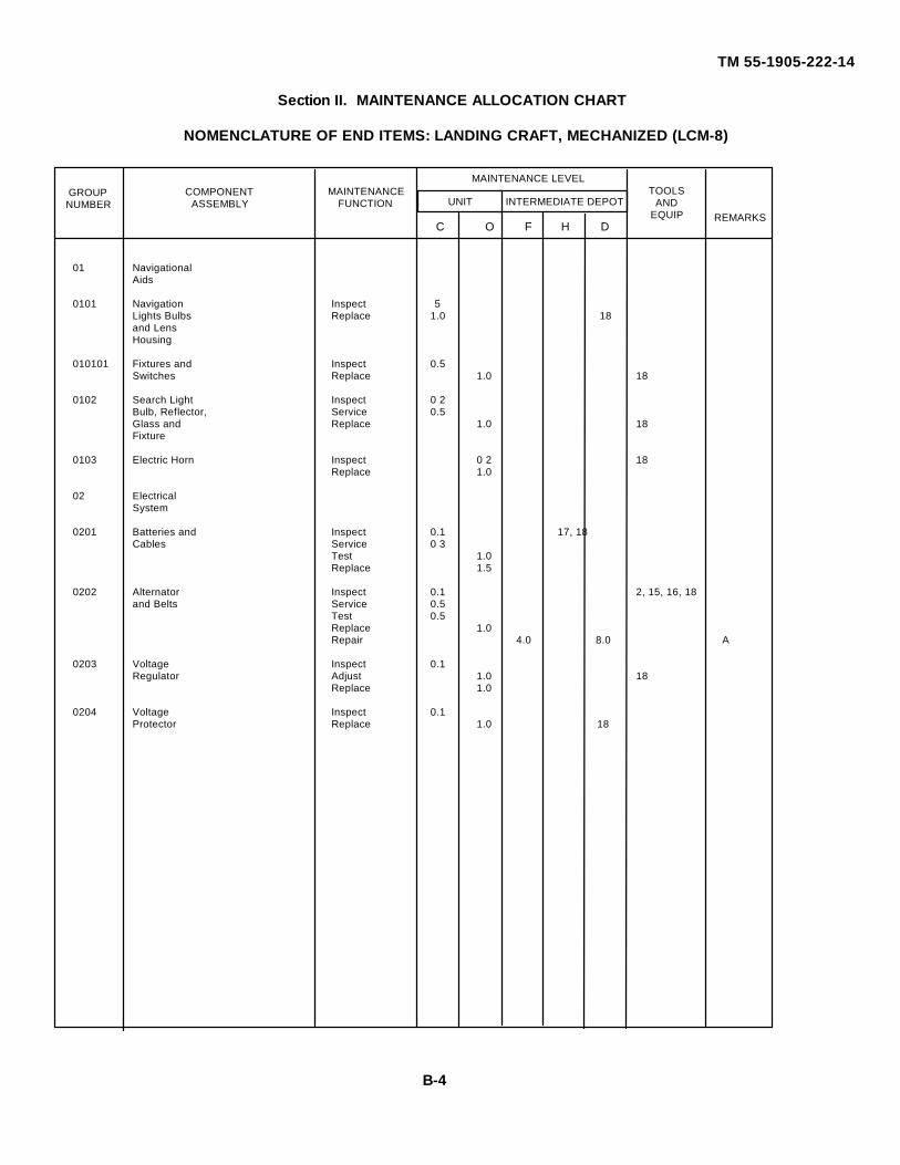
INTERMEDIATE DEPOT
TM 55-1905-222-14
Section II. MAINTENANCE ALLOCATION CHART
NOMENCLATURE OF END ITEMS: LANDING CRAFT, MECHANIZED (LCM-8)
01 NavigationalAids
0101 Navigation Inspect 5Lights Bulbs Replace 1.0 18and LensHousing
010101 Fixtures and Inspect 0.5Switches Replace 1.0 18
0102 Search Light Inspect 0 2Bulb, Reflector, Service 0.5Glass and Replace 1.0 18Fixture
0103 Electric Horn Inspect 0 2 18Replace 1.0
02 ElectricalSystem
0201 Batteries and Inspect 0.1 17, 18Cables Service 0 3
Test 1.0Replace 1.5
0202 Alternator Inspect 0.1 2, 15, 16, 18and Belts Service 0.5
Test 0.5Replace 1.0Repair 4.0 8.0 A
0203 Voltage Inspect 0.1Regulator Adjust 1.0 18
Replace 1.0
0204 Voltage Inspect 0.1Protector Replace 1.0 18
TOOLSAND
EQUIP
MAINTENANCEFUNCTION
REMARKS
COMPONENTASSEMBLY
GROUPNUMBER
C O F H D
MAINTENANCE LEVEL
UNIT
B-4
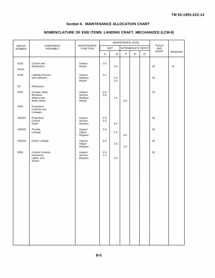
INTERMEDIATE DEPOT
TM 55-1905-222-14
Section II. MAINTENANCE ALLOCATION CHART
NOMENCLATURE OF END ITEMS: LANDING CRAFT, MECHANIZED (LCM-8)
0205 Control and Inspect 2.0Distribution Repair 2.0 18 B
Panel
0206 Lighting Fixtures Inspect 0.1and Switches Replace 1.0 18
Repair 1.0
03 Pilothouse
0301 Canopy, Mast, Inspect 0.5 18Windows, Service 0.5Wipers and Replace 4 5Wiper Motor Repair 6.0
0302 PropulsionControls andLinkages
030201 Propulsion Inspect 0.5 18Control Service 2.0Head Replace 4.0
030202 Throttle Inspect 0.5 18Linkage Adjust 1.5
Replace 4.0
030203 Clutch Linkage Inspect 0.5 18Adjust 1.5Replace 3.0
0303 Control Console, Inspect 0.5 18Instrument Service 1.0Lights, and Replace 2.0Switch
TOOLSAND
EQUIP
MAINTENANCEFUNCTION
REMARKS
COMPONENTASSEMBLY
GROUPNUMBER
C O F H D
MAINTENANCE LEVEL
UNIT
B-5

INTERMEDIATE DEPOT
TM 55-1905-222-14
Section II. MAINTENANCE ALLOCATION CHART
NOMENCLATURE OF END ITEMS: LANDING CRAFT, MECHANIZED (LCM-8)
030301 Engine/ Replace 2.0 18TransmissionInstruments
030302 Hydraulic Replace 2.0 18Gauges, RudderAngle Indicatorand Ammeter
0304 Engine Shutdown Replace 2.0 18Control andEmergencyEngine ShutdownControl
04 SanitationSystem
0401 MSD Assembly Inspect 1.0 18 CTreatment Tank, Service 2.0Receiving Tank, Replace 6.0Filter,DisinfectionUnit, RetentionCanisters, Hosesand Valves
0402 MSD Pump Inspect 0.1 18and Motor Service 0.1Assembly Replace 1.0
Repair 1.0
TOOLSAND
EQUIP
MAINTENANCEFUNCTION
REMARKS
COMPONENTASSEMBLY
GROUPNUMBER
C O F H D
MAINTENANCE LEVEL
UNIT
B-6
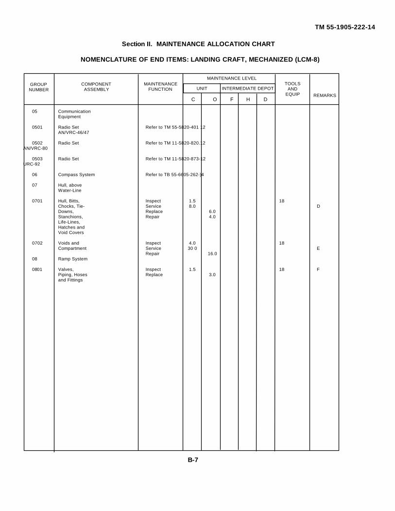
INTERMEDIATE DEPOT
TM 55-1905-222-14
Section II. MAINTENANCE ALLOCATION CHART
NOMENCLATURE OF END ITEMS: LANDING CRAFT, MECHANIZED (LCM-8)
05 CommunicationEquipment
0501 Radio Set Refer to TM 55-5820-401 12AN/VRC-46/47
0502 Radio Set Refer to TM 11-5820-820.12AN/VRC-80
0503 Radio Set Refer to TM 11-5820-873-12URC-92
06 Compass System Refer to TB 55-6605-262-)4
07 Hull, aboveWater-Line
0701 Hull, Bitts, Inspect 1.5 18Chocks, Tie- Service 8.0 DDowns, Replace 6.0Stanchions, Repair 4.0Life-Lines,Hatches andVoid Covers
0702 Voids and Inspect 4.0 18Compartment Service 30 0 E
Repair 16.008 Ramp System
0801 Valves, Inspect 1.5 18 FPiping, Hoses Replace 3.0and Fittings
TOOLSAND
EQUIP
MAINTENANCEFUNCTION
REMARKS
COMPONENTASSEMBLY
GROUPNUMBER
C O F H D
MAINTENANCE LEVEL
UNIT
B-7
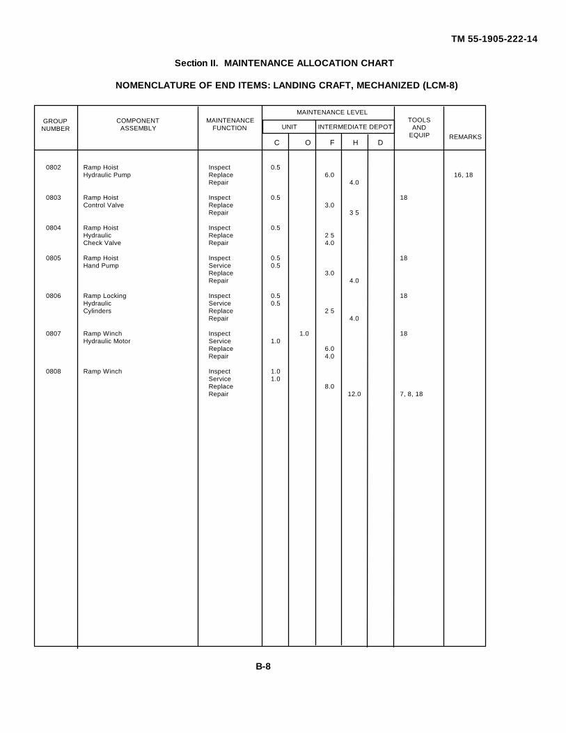
INTERMEDIATE DEPOT
TM 55-1905-222-14
Section II. MAINTENANCE ALLOCATION CHART
NOMENCLATURE OF END ITEMS: LANDING CRAFT, MECHANIZED (LCM-8)
0802 Ramp Hoist Inspect 0.5Hydraulic Pump Replace 6.0 16, 18
Repair 4.0
0803 Ramp Hoist Inspect 0.5 18Control Valve Replace 3.0
Repair 3 5
0804 Ramp Hoist Inspect 0.5Hydraulic Replace 2 5Check Valve Repair 4.0
0805 Ramp Hoist Inspect 0.5 18Hand Pump Service 0.5
Replace 3.0Repair 4.0
0806 Ramp Locking Inspect 0.5 18Hydraulic Service 0.5Cylinders Replace 2 5
Repair 4.0
0807 Ramp Winch Inspect 1.0 18Hydraulic Motor Service 1.0
Replace 6.0Repair 4.0
0808 Ramp Winch Inspect 1.0Service 1.0Replace 8.0Repair 12.0 7, 8, 18
TOOLSAND
EQUIP
MAINTENANCEFUNCTION
REMARKS
COMPONENTASSEMBLY
GROUPNUMBER
C O F H D
MAINTENANCE LEVEL
UNIT
B-8
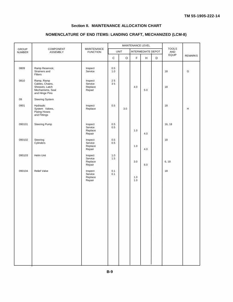
INTERMEDIATE DEPOT
TM 55-1905-222-14
Section II. MAINTENANCE ALLOCATION CHART
NOMENCLATURE OF END ITEMS: LANDING CRAFT, MECHANIZED (LCM-8)
0809 Ramp Reservoir, Inspect 0.5Strainers and Service 1.0 18 GFilters
0810 Ramp, Ramp Inspect 2 5Cables, Chains, Service 3 5Sheaves, Latch Replace 4.0 18Mechanisms, Seal Repair 5 0and Hinge Pins
09 Steering System
0901 Hydraulic Inspect 0.5 18System Valves, Replace 3.0 HPiping Hosesand Fittings
090101 Steering Pump Inspect 0.5 16, 18Service 0.5Replace 1.0Repair 4.0
090102 Steering Inspect 0.5 18Cylinders Service 0.5
Replace 1.0Repair 4.0
090103 Helm Unit Inspect 1.0Service 1.5Replace 3.0 6, 18Repair 6.0
090104 Relief Valve Inspect 0.1 18Service 0.1Replace 1.0Repair 1.0
TOOLSAND
EQUIP
MAINTENANCEFUNCTION
REMARKS
COMPONENTASSEMBLY
GROUPNUMBER
C O F H D
MAINTENANCE LEVEL
UNIT
B-9
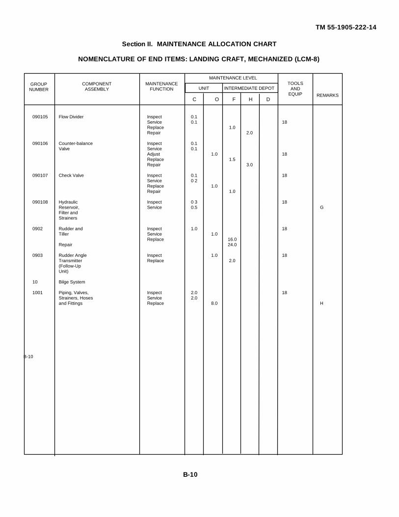
INTERMEDIATE DEPOT
TM 55-1905-222-14
Section II. MAINTENANCE ALLOCATION CHART
NOMENCLATURE OF END ITEMS: LANDING CRAFT, MECHANIZED (LCM-8)
090105 Flow Divider Inspect 0.1Service 0.1 18Replace 1.0Repair 2.0
090106 Counter-balance Inspect 0.1Valve Service 0.1
Adjust 1.0 18Replace 1.5Repair 3.0
090107 Check Valve Inspect 0.1 18Service 0 2Replace 1.0Repair 1.0
090108 Hydraulic Inspect 0 3 18Reservoir, Service 0.5 GFilter andStrainers
0902 Rudder and Inspect 1.0 18Tiller Service 1.0
Replace 16.0Repair 24.0
0903 Rudder Angle Inspect 1.0 18Transmitter Replace 2.0(Follow-UpUnit)
10 Bilge System
1001 Piping, Valves, Inspect 2.0 18Strainers, Hoses Service 2.0and Fittings Replace 8.0 H
B-10
TOOLSAND
EQUIP
MAINTENANCEFUNCTION
REMARKS
COMPONENTASSEMBLY
GROUPNUMBER
C O F H D
MAINTENANCE LEVEL
UNIT
B-10
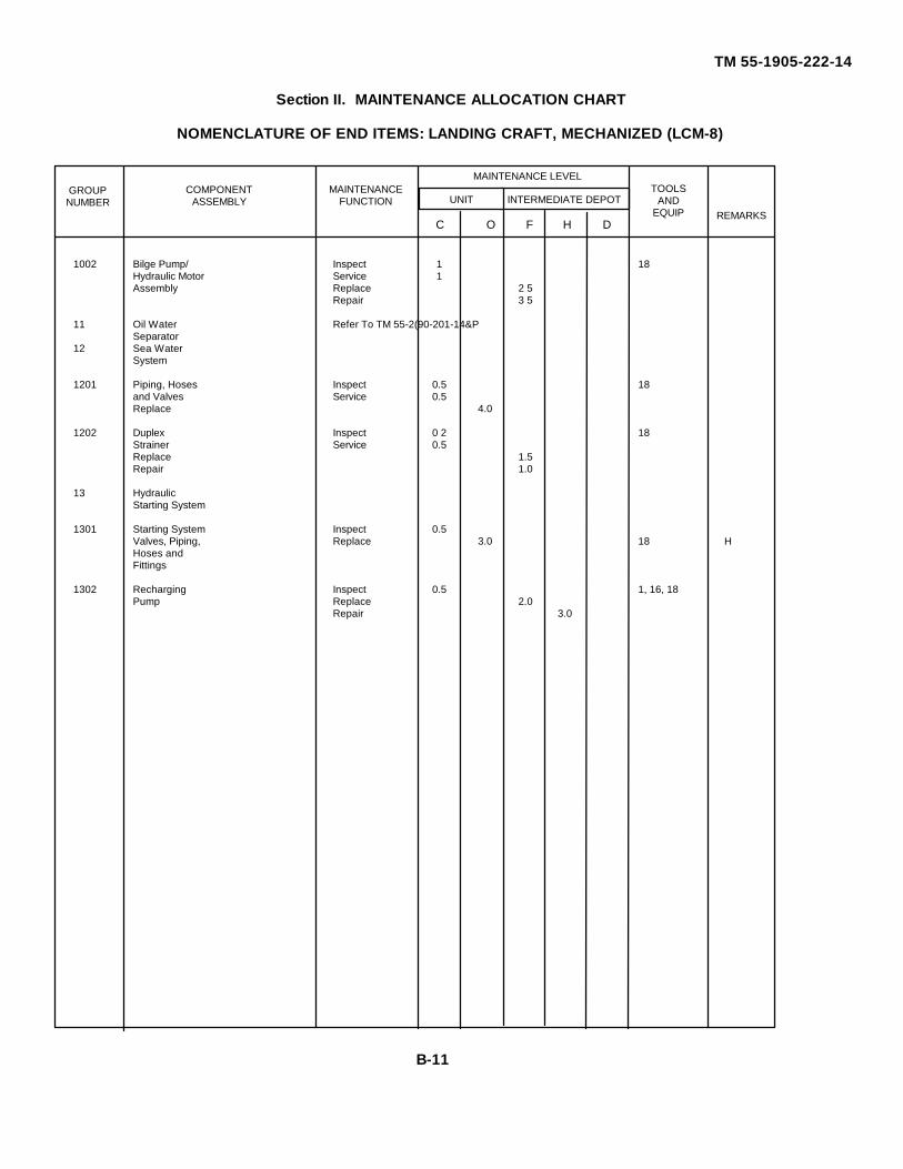
INTERMEDIATE DEPOT
TM 55-1905-222-14
Section II. MAINTENANCE ALLOCATION CHART
NOMENCLATURE OF END ITEMS: LANDING CRAFT, MECHANIZED (LCM-8)
1002 Bilge Pump/ Inspect 1 18Hydraulic Motor Service 1Assembly Replace 2 5
Repair 3 5
11 Oil Water Refer To TM 55-2(90-201-14&PSeparator
12 Sea WaterSystem
1201 Piping, Hoses Inspect 0.5 18and Valves Service 0.5Replace 4.0
1202 Duplex Inspect 0 2 18Strainer Service 0.5Replace 1.5Repair 1.0
13 HydraulicStarting System
1301 Starting System Inspect 0.5Valves, Piping, Replace 3.0 18 HHoses andFittings
1302 Recharging Inspect 0.5 1, 16, 18Pump Replace 2.0
Repair 3.0
TOOLSAND
EQUIP
MAINTENANCEFUNCTION
REMARKS
COMPONENTASSEMBLY
GROUPNUMBER
C O F H D
MAINTENANCE LEVEL
UNIT
B-11
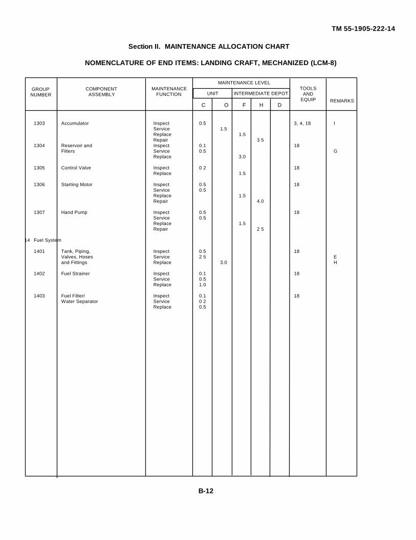
INTERMEDIATE DEPOT
TM 55-1905-222-14
Section II. MAINTENANCE ALLOCATION CHART
NOMENCLATURE OF END ITEMS: LANDING CRAFT, MECHANIZED (LCM-8)
1303 Accumulator Inspect 0.5 3, 4, 18 IService 1.5Replace 1.5Repair 3 5
1304 Reservoir and Inspect 0.1 18Filters Service 0.5 G
Replace 3.0
1305 Control Valve Inspect 0 2 18Replace 1.5
1306 Starting Motor Inspect 0.5 18Service 0.5Replace 1.5Repair 4.0
1307 Hand Pump Inspect 0.5 18Service 0.5Replace 1.5Repair 2 5
14 Fuel System
1401 Tank, Piping, Inspect 0.5 18Valves, Hoses Service 2 5 Eand Fittings Replace 3.0 H
1402 Fuel Strainer Inspect 0.1 18Service 0.5Replace 1.0
1403 Fuel Filter/ Inspect 0.1 18Water Separator Service 0 2
Replace 0.5
TOOLSAND
EQUIP
MAINTENANCEFUNCTION
REMARKS
COMPONENTASSEMBLY
GROUPNUMBER
C O F H D
MAINTENANCE LEVEL
UNIT
B-12
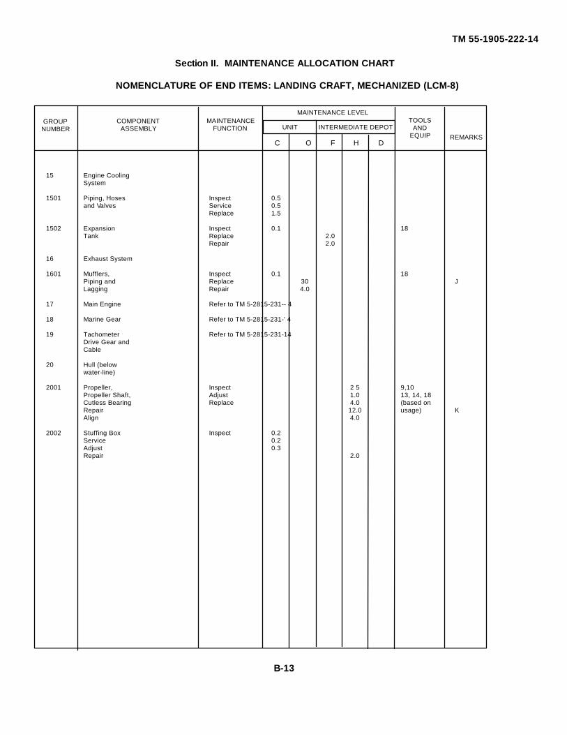
INTERMEDIATE DEPOT
TM 55-1905-222-14
Section II. MAINTENANCE ALLOCATION CHART
NOMENCLATURE OF END ITEMS: LANDING CRAFT, MECHANIZED (LCM-8)
15 Engine CoolingSystem
1501 Piping, Hoses Inspect 0.5and Valves Service 0.5
Replace 1.5
1502 Expansion Inspect 0.1 18Tank Replace 2.0
Repair 2.0
16 Exhaust System
1601 Mufflers, Inspect 0.1 18Piping and Replace 30 JLagging Repair 4.0
17 Main Engine Refer to TM 5-2815-231-- 4
18 Marine Gear Refer to TM 5-2815-231-' 4
19 Tachometer Refer to TM 5-2815-231-14Drive Gear andCable
20 Hull (belowwater-line)
2001 Propeller, Inspect 2 5 9,10Propeller Shaft, Adjust 1.0 13, 14, 18Cutless Bearing Replace 4.0 (based onRepair 12.0 usage) KAlign 4.0
2002 Stuffing Box Inspect 0.2Service 0.2Adjust 0.3Repair 2.0
TOOLSAND
EQUIP
MAINTENANCEFUNCTION
REMARKS
COMPONENTASSEMBLY
GROUPNUMBER
C O F H D
MAINTENANCE LEVEL
UNIT
B-13
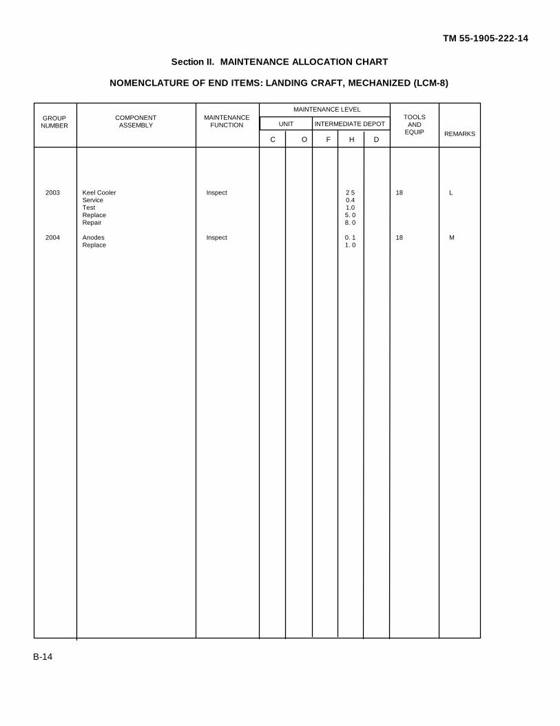
INTERMEDIATE DEPOT
TM 55-1905-222-14
Section II. MAINTENANCE ALLOCATION CHART
NOMENCLATURE OF END ITEMS: LANDING CRAFT, MECHANIZED (LCM-8)
2003 Keel Cooler Inspect 2 5 18 LService 0.4Test 1.0Replace 5. 0Repair 8. 0
2004 Anodes Inspect 0. 1 18 MReplace 1. 0
B-14
TOOLSAND
EQUIP
MAINTENANCEFUNCTION
REMARKS
COMPONENTASSEMBLY
GROUPNUMBER
C O F H D
MAINTENANCE LEVEL
UNIT
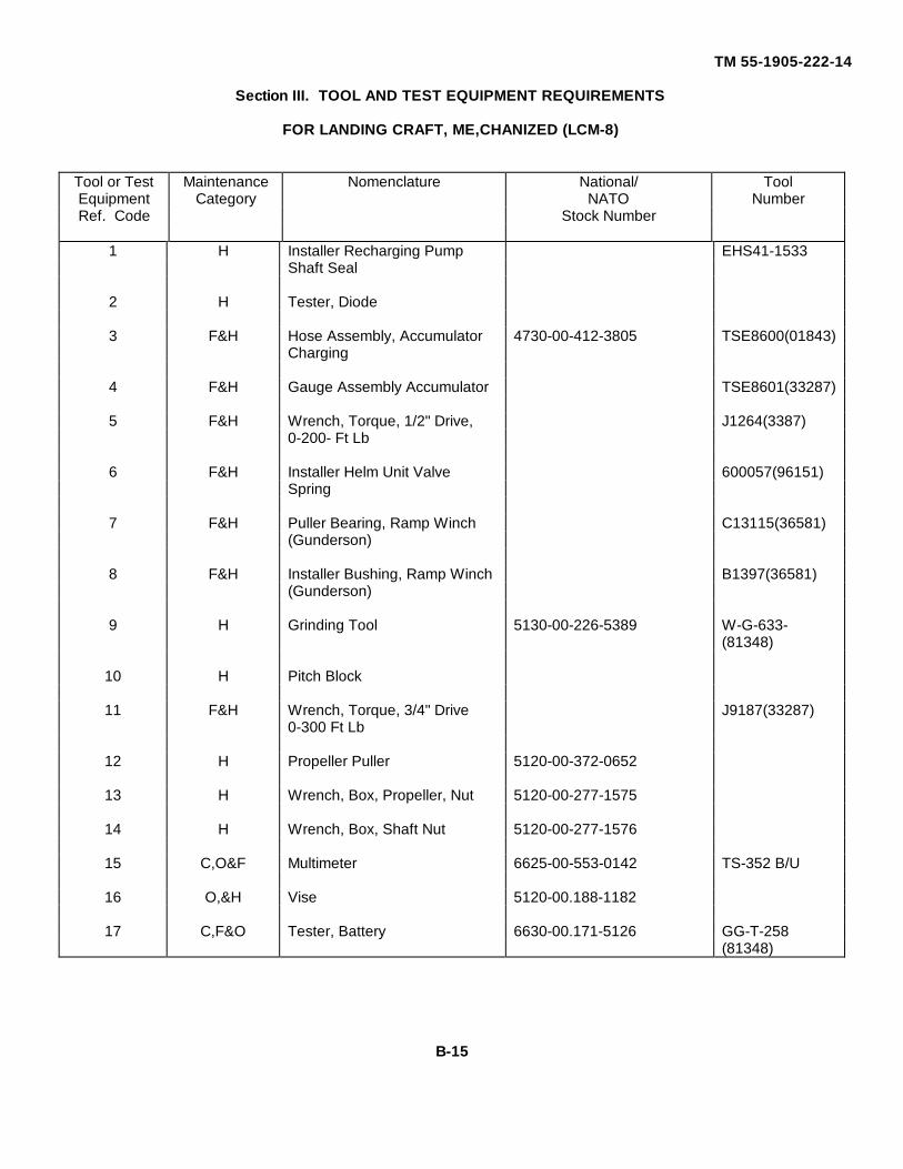
TM 55-1905-222-14
Section III. TOOL AND TEST EQUIPMENT REQUIREMENTS
FOR LANDING CRAFT, ME,CHANIZED (LCM-8)
Tool or Test Maintenance Nomenclature National/ ToolEquipment Category NATO NumberRef. Code Stock Number
1 H Installer Recharging Pump EHS41-1533Shaft Seal
2 H Tester, Diode
3 F&H Hose Assembly, Accumulator 4730-00-412-3805 TSE8600(01843)Charging
4 F&H Gauge Assembly Accumulator TSE8601(33287)
5 F&H Wrench, Torque, 1/2" Drive, J1264(3387)0-200- Ft Lb
6 F&H Installer Helm Unit Valve 600057(96151)Spring
7 F&H Puller Bearing, Ramp Winch C13115(36581)(Gunderson)
8 F&H Installer Bushing, Ramp Winch B1397(36581)(Gunderson)
9 H Grinding Tool 5130-00-226-5389 W-G-633-(81348)
10 H Pitch Block
11 F&H Wrench, Torque, 3/4" Drive J9187(33287)0-300 Ft Lb
12 H Propeller Puller 5120-00-372-0652
13 H Wrench, Box, Propeller, Nut 5120-00-277-1575
14 H Wrench, Box, Shaft Nut 5120-00-277-1576
15 C,O&F Multimeter 6625-00-553-0142 TS-352 B/U
16 O,&H Vise 5120-00.188-1182
17 C,F&O Tester, Battery 6630-00.171-5126 GG-T-258(81348)
B-15
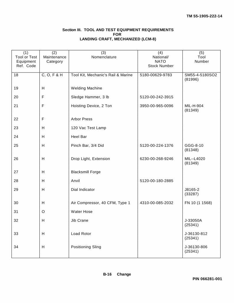
TM 55-1905-222-14
Section III. TOOL AND TEST EQUIPMENT REQUIREMENTSFOR
LANDING CRAFT, MECHANIZED (LCM-8)
(1)Tool or Test
(2)Maintenance
(3)Nomenclature
(4)National/
(5)Tool
Equipment Category NATO NumberRef. Code Stock Number
18 C, O, F & H Tool Kit, Mechanic's Rail & Marine 5180-00629-9783 SM55-4-5180SO2(81996)
19 H Welding Machine
20 F Sledge Hammer, 3 lb 5120-00-242-3915
21 F Hoisting Device, 2 Ton 3950-00-965-0096 MIL-H-904(81349)
22 F Arbor Press
23 H 120 Vac Test Lamp
24 H Heel Bar
25 H Pinch Bar, 3/4 Did 5120-00-224-1376 GGG-8-10(81348)
26 H Drop Light, Extension 6230-00-268-9246 MIL--L4020(81349)
27 H Blacksmill Forge
28 H Anvil 5120-00-180-2885
29 H Dial Indicator J8165-2(33287)
30 H Air Compressor, 40 CFM, Type 1 4310-00-085-2032 FN 10 (1 1568)
31 O Water Hose
32 H Jib Crane J-33050A(25341)
33 H Load Rotor J-36130-812(25341)
34 H Positioning Sling J-36130-806(25341)
B-16 ChangePIN 066281-001
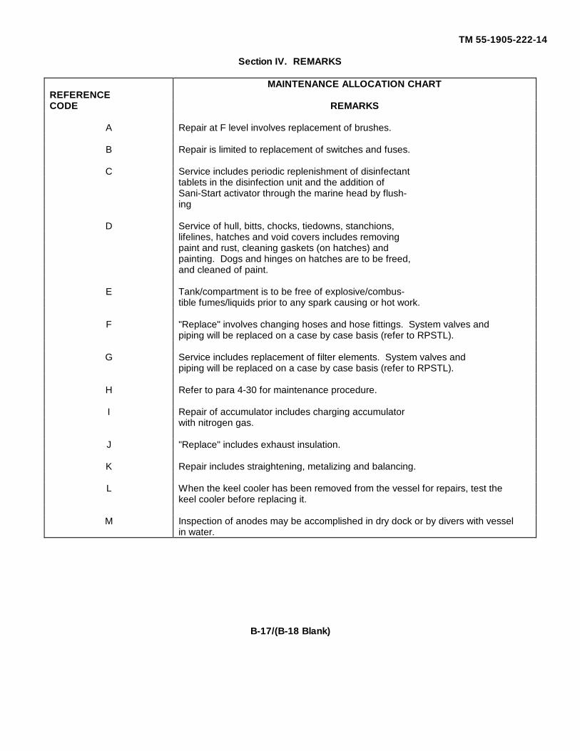
TM 55-1905-222-14
Section IV. REMARKS
MAINTENANCE ALLOCATION CHARTREFERENCECODE REMARKS
A Repair at F level involves replacement of brushes.
B Repair is limited to replacement of switches and fuses.
C Service includes periodic replenishment of disinfectanttablets in the disinfection unit and the addition ofSani-Start activator through the marine head by flush-ing
D Service of hull, bitts, chocks, tiedowns, stanchions,lifelines, hatches and void covers includes removingpaint and rust, cleaning gaskets (on hatches) andpainting. Dogs and hinges on hatches are to be freed,and cleaned of paint.
E Tank/compartment is to be free of explosive/combus-tible fumes/liquids prior to any spark causing or hot work.
F "Replace" involves changing hoses and hose fittings. System valves andpiping will be replaced on a case by case basis (refer to RPSTL).
G Service includes replacement of filter elements. System valves andpiping will be replaced on a case by case basis (refer to RPSTL).
H Refer to para 4-30 for maintenance procedure.
I Repair of accumulator includes charging accumulatorwith nitrogen gas.
J "Replace" includes exhaust insulation.
K Repair includes straightening, metalizing and balancing.
L When the keel cooler has been removed from the vessel for repairs, test thekeel cooler before replacing it.
M Inspection of anodes may be accomplished in dry dock or by divers with vesselin water.
B-17/(B-18 Blank)
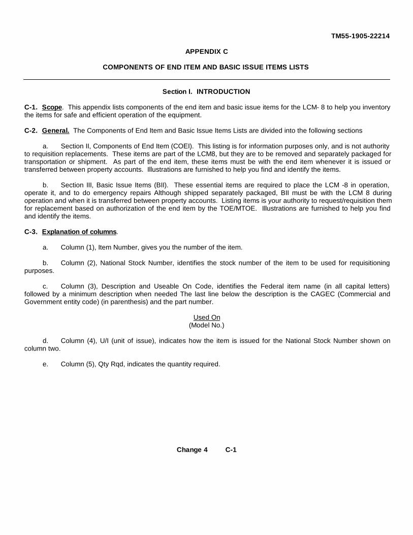
TM55-1905-22214
APPENDIX C
COMPONENTS OF END ITEM AND BASIC ISSUE ITEMS LISTS
Section I. INTRODUCTION
C-1. Scope. This appendix lists components of the end item and basic issue items for the LCM- 8 to help you inventorythe items for safe and efficient operation of the equipment.
C-2. General. The Components of End Item and Basic Issue Items Lists are divided into the following sections
a. Section II, Components of End Item (COEI). This listing is for information purposes only, and is not authorityto requisition replacements. These items are part of the LCM8, but they are to be removed and separately packaged fortransportation or shipment. As part of the end item, these items must be with the end item whenever it is issued ortransferred between property accounts. Illustrations are furnished to help you find and identify the items.
b. Section III, Basic Issue Items (BII). These essential items are required to place the LCM -8 in operation,operate it, and to do emergency repairs Although shipped separately packaged, BII must be with the LCM 8 duringoperation and when it is transferred between property accounts. Listing items is your authority to request/requisition themfor replacement based on authorization of the end item by the TOE/MTOE. Illustrations are furnished to help you findand identify the items.
C-3. Explanation of columns.
a. Column (1), Item Number, gives you the number of the item.
b. Column (2), National Stock Number, identifies the stock number of the item to be used for requisitioningpurposes.
c. Column (3), Description and Useable On Code, identifies the Federal item name (in all capital letters)followed by a minimum description when needed The last line below the description is the CAGEC (Commercial andGovernment entity code) (in parenthesis) and the part number.
Used On(Model No.)
d. Column (4), U/I (unit of issue), indicates how the item is issued for the National Stock Number shown oncolumn two.
e. Column (5), Qty Rqd, indicates the quantity required.
Change 4 C-1
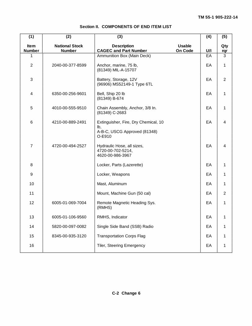
TM 55-1 905-222-14
Section II. COMPONENTS OF END ITEM LIST
(1) (2) (3) (4) (5)
Item National Stock Description Usable QtyNumber Number CAGEC and Part Number On Code U/I rqr
1 Ammunition Box (Main Deck) EA 3
2 2040-00-377-8599 Anchor, marine, 75 lb, EA 1(81349) MIL-A-15707
3 Battery, Storage, 12V EA 2(96906) MS52149-1 Type 6TL
4 6350-00-256-9601 Bell, Ship 20 lb EA 1(81349) B-674
5 4010-00-555-9510 Chain Assembly, Anchor, 3/8 In. EA 1(81349) C-2683
6 4210-00-889-2491 Extinguisher, Fire, Dry Chemical, 10 EA 4lb,A-B-C, USCG Approved (81348)O-E910
7 4720-00-494-2527 Hydraulic Hose, all sizes, EA 44720-00-702-5214,4620-00-986-3967
8 Locker, Parts (Lazerette) EA 1
9 Locker, Weapons EA 1
10 Mast, Aluminum EA 1
11 Mount, Machine Gun (50 cal) EA 2
12 6005-01-069-7004 Remote Magnetic Heading Sys. EA 1(RMHS)
13 6005-01-106-9560 RMHS, Indicator EA 1
14 5820-00-097-0082 Single Side Band (SSB) Radio EA 1
15 8345-00-935-3120 Transportation Corps Flag EA 1
16 Tiler, Steering Emergency EA 1
C-2 Change 6
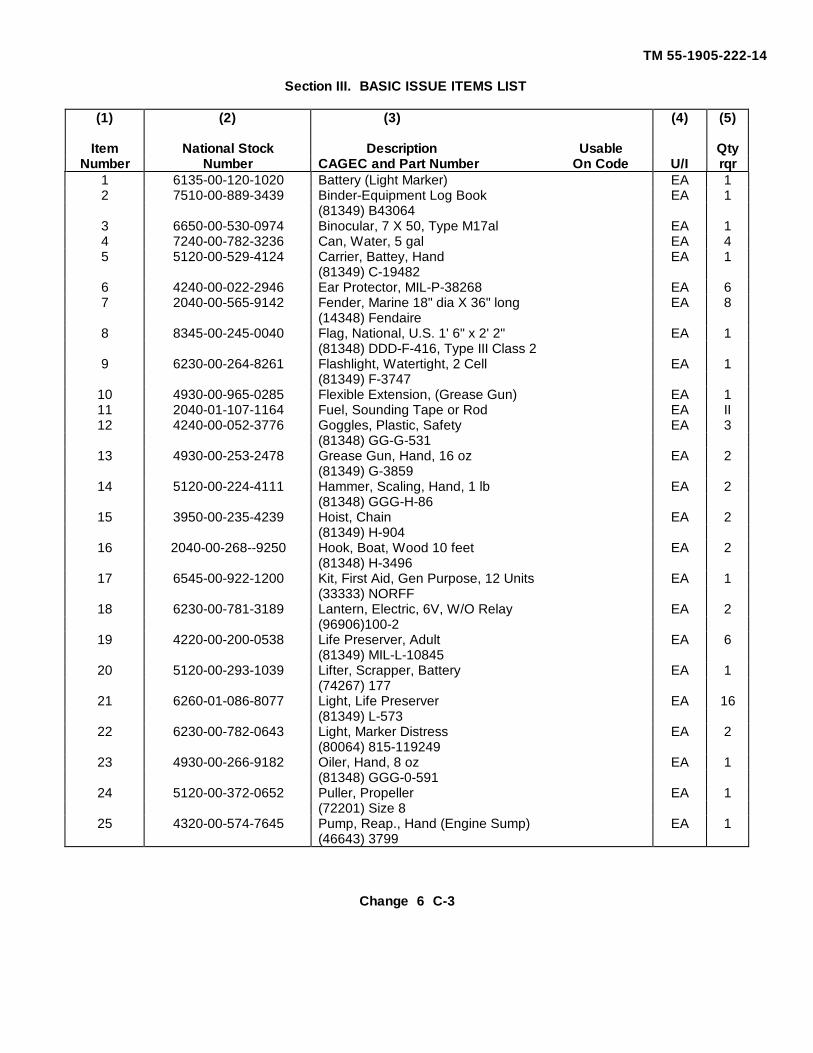
TM 55-1905-222-14
Section III. BASIC ISSUE ITEMS LIST
(1) (2) (3) (4) (5)
Item National Stock Description Usable QtyNumber Number CAGEC and Part Number On Code U/I rqr
1 6135-00-120-1020 Battery (Light Marker) EA 12 7510-00-889-3439 Binder-Equipment Log Book EA 1
(81349) B430643 6650-00-530-0974 Binocular, 7 X 50, Type M17al EA 14 7240-00-782-3236 Can, Water, 5 gal EA 45 5120-00-529-4124 Carrier, Battey, Hand EA 1
(81349) C-194826 4240-00-022-2946 Ear Protector, MIL-P-38268 EA 67 2040-00-565-9142 Fender, Marine 18" dia X 36" long EA 8
(14348) Fendaire8 8345-00-245-0040 Flag, National, U.S. 1' 6" x 2' 2" EA 1
(81348) DDD-F-416, Type III Class 29 6230-00-264-8261 Flashlight, Watertight, 2 Cell EA 1
(81349) F-374710 4930-00-965-0285 Flexible Extension, (Grease Gun) EA 111 2040-01-107-1164 Fuel, Sounding Tape or Rod EA II12 4240-00-052-3776 Goggles, Plastic, Safety EA 3
(81348) GG-G-53113 4930-00-253-2478 Grease Gun, Hand, 16 oz EA 2
(81349) G-385914 5120-00-224-4111 Hammer, Scaling, Hand, 1 lb EA 2
(81348) GGG-H-8615 3950-00-235-4239 Hoist, Chain EA 2
(81349) H-90416 2040-00-268--9250 Hook, Boat, Wood 10 feet EA 2
(81348) H-349617 6545-00-922-1200 Kit, First Aid, Gen Purpose, 12 Units EA 1
(33333) NORFF18 6230-00-781-3189 Lantern, Electric, 6V, W/O Relay EA 2
(96906)100-219 4220-00-200-0538 Life Preserver, Adult EA 6
(81349) MIL-L-1084520 5120-00-293-1039 Lifter, Scrapper, Battery EA 1
(74267) 17721 6260-01-086-8077 Light, Life Preserver EA 16
(81349) L-57322 6230-00-782-0643 Light, Marker Distress EA 2
(80064) 815-11924923 4930-00-266-9182 Oiler, Hand, 8 oz EA 1
(81348) GGG-0-59124 5120-00-372-0652 Puller, Propeller EA 1
(72201) Size 825 4320-00-574-7645 Pump, Reap., Hand (Engine Sump) EA 1
(46643) 3799
Change 6 C-3
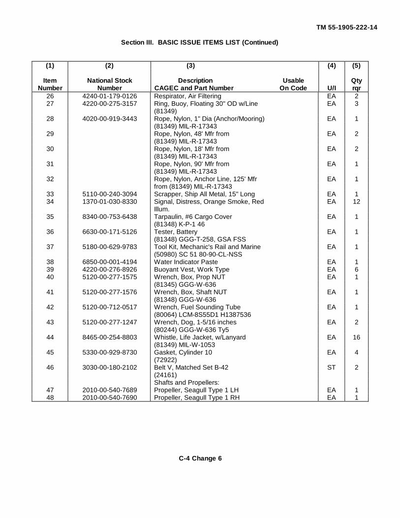
TM 55-1905-222-14
Section III. BASIC ISSUE ITEMS LIST (Continued)
(1) (2) (3) (4) (5)
Item National Stock Description Usable QtyNumber Number CAGEC and Part Number On Code U/I rqr
26 4240-01-179-0126 Respirator, Air Filtering EA 227 4220-00-275-3157 Ring, Buoy, Floating 30" OD w/Line EA 3
(81349)28 4020-00-919-3443 Rope, Nylon, 1" Dia (Anchor/Mooring) EA 1
(81349) MIL-R-1734329 Rope, Nylon, 48' Mfr from EA 2
(81349) MIL-R-1734330 Rope, Nylon, 18' Mfr from EA 2
(81349) MIL-R-1734331 Rope, Nylon, 90' Mfr from EA 1
(81349) MIL-R-1734332 Rope, Nylon, Anchor Line, 125' Mfr EA 1
from (81349) MIL-R-1734333 5110-00-240-3094 Scrapper, Ship All Metal, 15" Long EA 134 1370-01-030-8330 Signal, Distress, Orange Smoke, Red EA 12
Illum.35 8340-00-753-6438 Tarpaulin, #6 Cargo Cover EA 1
(81348) K-P-1 4636 6630-00-171-5126 Tester, Battery EA 1
(81348) GGG-T-258, GSA FSS37 5180-00-629-9783 Tool Kit, Mechanic's Rail and Marine EA 1
(50980) SC 51 80-90-CL-NSS38 6850-00-001-4194 Water Indicator Paste EA 139 4220-00-276-8926 Buoyant Vest, Work Type EA 640 5120-00-277-1575 Wrench, Box, Prop NUT EA 1
(81345) GGG-W-63641 5120-00-277-1576 Wrench, Box, Shaft NUT EA 1
(81348) GGG-W-63642 5120-00-712-0517 Wrench, Fuel Sounding Tube EA 1
(80064) LCM-8S55D1 H138753643 5120-00-277-1247 Wrench, Dog, 1-5/16 inches EA 2
(80244) GGG-W-636 Ty544 8465-00-254-8803 Whistle, Life Jacket, w/Lanyard EA 16
(81349) MIL-W-105345 5330-00-929-8730 Gasket, Cylinder 10 EA 4
(72922)46 3030-00-180-2102 Belt V, Matched Set B-42 ST 2
(24161)Shafts and Propellers:
47 2010-00-540-7689 Propeller, Seagull Type 1 LH EA 148 2010-00-540-7690 Propeller, Seagull Type 1 RH EA 1
C-4 Change 6
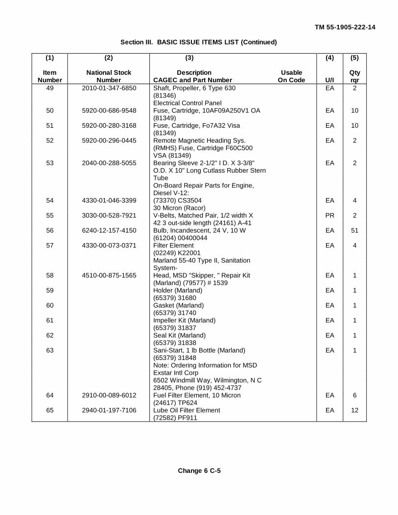
TM 55-1905-222-14
Section III. BASIC ISSUE ITEMS LIST (Continued)
(1) (2) (3) (4) (5)
Item National Stock Description Usable QtyNumber Number CAGEC and Part Number On Code U/I rqr
49 2010-01-347-6850 Shaft, Propeller, 6 Type 630 EA 2(81346)Electrical Control Panel
50 5920-00-686-9548 Fuse, Cartridge, 10AF09A250V1 OA EA 10(81349)
51 5920-00-280-3168 Fuse, Cartridge, Fo7A32 Visa EA 10(81349)
52 5920-00-296-0445 Remote Magnetic Heading Sys. EA 2(RMHS) Fuse, Cartridge F60C500VSA (81349)
53 2040-00-288-5055 Bearing Sleeve 2-1/2" I D. X 3-3/8" EA 2O.D. X 10" Long Cutlass Rubber SternTubeOn-Board Repair Parts for Engine,Diesel V-12:
54 4330-01-046-3399 (73370) CS3504 EA 430 Micron (Racor)
55 3030-00-528-7921 V-Belts, Matched Pair, 1/2 width X PR 242 3 out-side length (24161) A-41
56 6240-12-157-4150 Bulb, Incandescent, 24 V, 10 W EA 51(61204) 00400044
57 4330-00-073-0371 Filter Element EA 4(02249) K22001Marland 55-40 Type II, SanitationSystem-
58 4510-00-875-1565 Head, MSD "Skipper, " Repair Kit EA 1(Marland) (79577) # 1539
59 Holder (Marland) EA 1(65379) 31680
60 Gasket (Marland) EA 1(65379) 31740
61 Impeller Kit (Marland) EA 1(65379) 31837
62 Seal Kit (Marland) EA 1(65379) 31838
63 Sani-Start, 1 lb Bottle (Marland) EA 1(65379) 31848Note: Ordering Information for MSDExstar Intl Corp6502 Windmill Way, Wilmington, N C28405, Phone (919) 452-4737
64 2910-00-089-6012 Fuel Filter Element, 10 Micron EA 6(24617) TP624
65 2940-01-197-7106 Lube Oil Filter Element EA 12(72582) PF911
Change 6 C-5
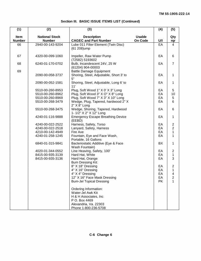
TM 55-1905-222-14
Section III. BASIC ISSUE ITEMS LIST (Continued)
(1) (2) (3) (4) (5)
Item National Stock Description Usable QtyNumber Number CAGEC and Part Number On Code U/I rqr
66 2940-00-143-9204 Lube 011 Filter Element (Twin Disc) EA 4(61 208)ump
67 4320-00-099-1060 Impeller, Raw Water Pump EA 6(72582) 5193602
68 6240-01-170-0702 Bulb, Incandescent 24V, 25 W EA 7(61204) 904-00003
69 Battle Damage Equipment2090-00-058-3737 Shoring, Steel, Adjustable, Short 3' to EA 1
5”2090-00-052-1581 Shoring, Steel, Adjustable, Long 6' to EA 1
11'5510-00-260-8953 Plug, Soft Wood 1" X 0' X 3" Long EA 55510-00-260-8962 Plug, Soft Wood 3" X O" X 8" Long EA 105510-00-260-8969 Plug, Soft Wood 7" X 3" X 10" Long EA 55510-00-268-3479 Wedge, Plug, Tapered, hardwood 2" X EA 6
2" X 8" Long5510-00-268-3475 Wedge, Shoring, Tapered, Hardwood EA 6
1- 1/2" X 2" X 12" Long4240-01-116-9888 Emergency Escape Breathing Device EA 1
(EEBD)4240-00-022-2522 Harness, Safety, Torso EA 24240-00-022-2518 Lanyard, Safety, Harness EA 24210-00-142-4949 Fire Axe EA 14240-01-258-1245 Fountain, Eye and Face Wash, EA 1
Portable, 16 Gallons6840-01-315-9841 Bacteriostatic Additive (Eye & Face BX 1
Wash Fountain)4020-01-344-0552 Line Heaving, Safety, 100' EA 28415-00-935-3139 Hard Hat, White EA 18415-00-935-3136 Hard Hat, Orange EA 3
Bum Dressing Kit:8" X 18" Dressing EA 24" X 16" Dressing EA 14" X 4" Dressing EA 412" X 16" Face Mask Dressing EA 2Bum-Jel Topical Dressing PK 1
Ordering Information:Water-Jel Awk KitH & H Associates, IncP O. Box 4469Alexandria, Va. 22303Phone 1-800-236-5708
C-6 Change 6
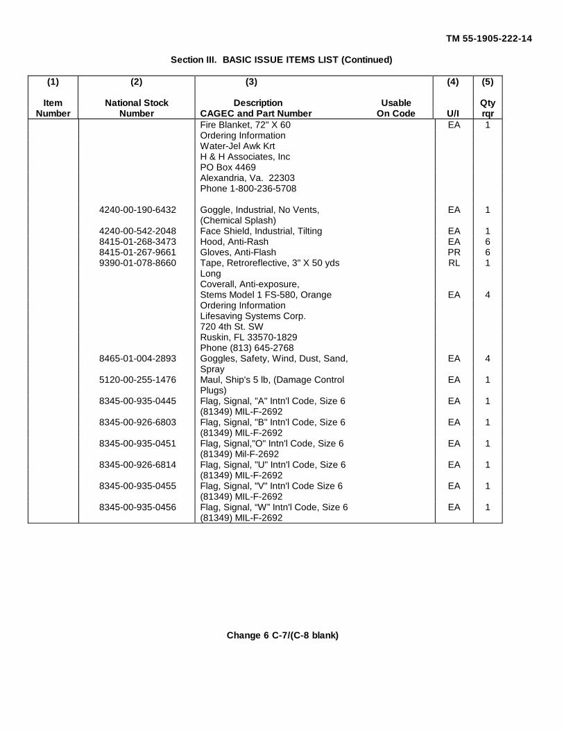
TM 55-1905-222-14
Section III. BASIC ISSUE ITEMS LIST (Continued)
(1) (2) (3) (4) (5)
Item National Stock Description Usable QtyNumber Number CAGEC and Part Number On Code U/I rqr
Fire Blanket, 72" X 60 EA 1Ordering InformationWater-Jel Awk KrtH & H Associates, IncPO Box 4469Alexandria, Va. 22303Phone 1-800-236-5708
4240-00-190-6432 Goggle, Industrial, No Vents, EA 1(Chemical Splash)
4240-00-542-2048 Face Shield, Industrial, Tilting EA 18415-01-268-3473 Hood, Anti-Rash EA 68415-01-267-9661 Gloves, Anti-Flash PR 69390-01-078-8660 Tape, Retroreflective, 3" X 50 yds RL 1
LongCoverall, Anti-exposure,Stems Model 1 FS-580, Orange EA 4Ordering InformationLifesaving Systems Corp.720 4th St. SWRuskin, FL 33570-1829Phone (813) 645-2768
8465-01-004-2893 Goggles, Safety, Wind, Dust, Sand, EA 4Spray
5120-00-255-1476 Maul, Ship's 5 lb, (Damage Control EA 1Plugs)
8345-00-935-0445 Flag, Signal, "A" Intn'l Code, Size 6 EA 1(81349) MIL-F-2692
8345-00-926-6803 Flag, Signal, "B" Intn'l Code, Size 6 EA 1(81349) MIL-F-2692
8345-00-935-0451 Flag, Signal,"O" Intn'l Code, Size 6 EA 1(81349) Mil-F-2692
8345-00-926-6814 Flag, Signal, "U" Intn'l Code, Size 6 EA 1(81349) MIL-F-2692
8345-00-935-0455 Flag, Signal, "V" Intn'l Code Size 6 EA 1(81349) MIL-F-2692
8345-00-935-0456 Flag, Signal, “W” Intn'l Code, Size 6 EA 1(81349) MIL-F-2692
Change 6 C-7/(C-8 blank)
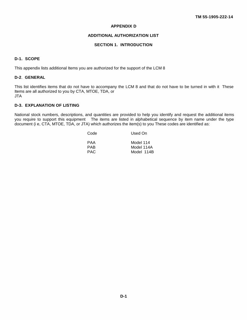
TM 55-1905-222-14
APPENDIX D
ADDITIONAL AUTHORIZATION LIST
SECTION 1. INTRODUCTION
D-1. SCOPE
This appendix lists additional Items you are authorized for the support of the LCM 8
D-2. GENERAL
This list identifies items that do not have to accompany the LCM 8 and that do not have to be turned in with it TheseItems are all authorized to you by CTA, MTOE, TDA, orJTA
D-3. EXPLANATION OF LISTING
National stock numbers, descriptions, and quantities are provided to help you identify and request the additional itemsyou require to support this equipment The items are listed in alphabetical sequence by item name under the typedocument (i e, CTA, MTOE, TDA, or JTA) which authorizes the item(s) to you These codes are identified as:
Code Used On
PAA Model 114PAB Model 114APAC Model 114B
D-1
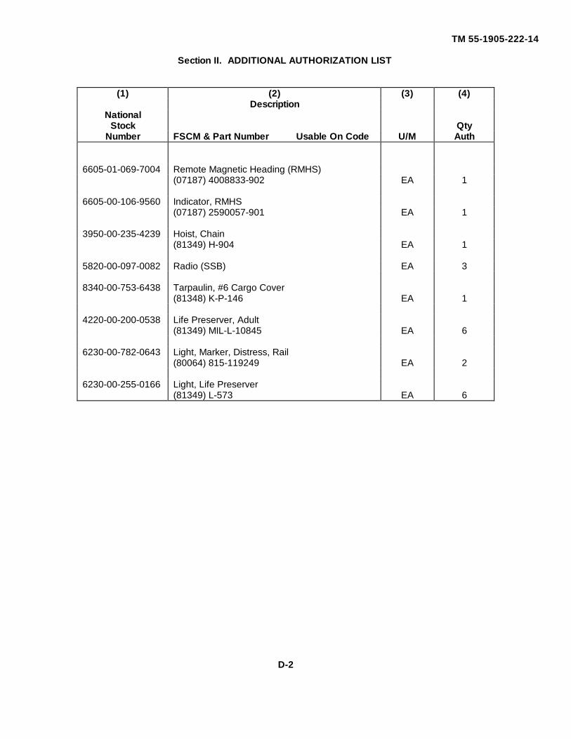
TM 55-1905-222-14
Section II. ADDITIONAL AUTHORIZATION LIST
(1) (2) (3) (4)Description
NationalStock Qty
Number FSCM & Part Number Usable On Code U/M Auth
6605-01-069-7004 Remote Magnetic Heading (RMHS)(07187) 4008833-902 EA 1
6605-00-106-9560 Indicator, RMHS(07187) 2590057-901 EA 1
3950-00-235-4239 Hoist, Chain(81349) H-904 EA 1
5820-00-097-0082 Radio (SSB) EA 3
8340-00-753-6438 Tarpaulin, #6 Cargo Cover(81348) K-P-146 EA 1
4220-00-200-0538 Life Preserver, Adult(81349) MIL-L-10845 EA 6
6230-00-782-0643 Light, Marker, Distress, Rail(80064) 815-119249 EA 2
6230-00-255-0166 Light, Life Preserver(81349) L-573 EA 6
D-2
TM 55-1905-222-14
APPENDIX E
EXPENDABLE SUPPLIES AND MATERIALS LIST
SECTION 1. INTRODUCTION
E-I. SCOPE
This appendix lists expendable supplies and materials you will need to operate and maintain the LCM 8These Items are authorized to you by CTA 50-970, Expendable Items (Except Medical, Class V, RepairParts, and Heraldic Items)
E-2. EXPLANATION OF COLUMNS
a. Column (I) - Item Number This number is assigned to the entry In the listing and is referenced In thenarrative Instructions to identify the material (e.g , "Use cleaning compound, item 5, App.E").
b. Column (2) - Level. This column identifies the lowest level of maintenance that requires the listed Item.
(enter as applicable)
C - Operator/CrewO - Organizational MaintenanceF- Direct Support MaintenanceH - General Support Maintenance
c. Column (3) - National Stock Number This is the National stock number assigned to the item, use it torequest or requisition the item.
d. Column (4) - Description Indicates the Federal item name and, if required, a description to identify the item.The last line for each item indicates the Federal Supply Code for Manufacturer (FSCM) in parenthesis followed by thepart number
e. Column (5) - Unit of Measure (U/M) Indicates the measure used in performing the actual maintenancefunction. This measure is expressed by a two-character alphabetical abbreviation (e.g , ea, in, pr). If the unit of measurediffers from the unit of issue. requisition the lowest unit of issue that will satisfy your requirements.
E-1
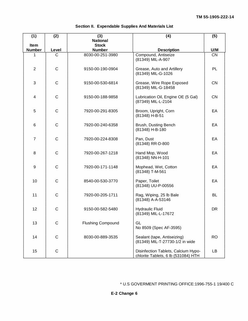
TM 55-1905-222-14
Section II. Expendable Supplies And Materials List
(1) (2) (3) (4) (5)National
Item StockNumber Level Number Description U/M
1 C 8030-00-251-3980 Compound, Antiseize CN(81349) MIL-A-907
2 C 9150-00-190-0904 Grease, Auto and Artillery PL(81349) MIL-G-1026
3 C 9150-00-530-6814 Grease, Wire Rope Exposed CN(81349) MIL-G-18458
4 C 9150-00-188-9858 Lubrication Oil, Engine OE (5 Gal) CN(87349) MIL-L-2104
5 C 7920-00-291-8305 Broom, Upright, Corn EA(81348) H-B-51
6 C 7920-00-240-6358 Brush, Dusting Bench EA(81348) H-B-180
7 C 7920-00-224-8308 Pan, Dust EA(81348) RR-D-800
8 C 7920-00-267-1218 Hand Mop, Wood EA(81348) NN-H-101
9 C 7920-00-171-1148 Mophead, Wet, Cotton EA(81348) T-M-561
10 C 8540-00-530-3770 Paper, Toilet EA(81348) UU-P-00556
11 C 7920-00-205-1711 Rag, Wiping, 25 lb Bale BL(81348) A-A-53146
12 C 9150-00-582-5480 Hydraulic Fluid DR(81349) MIL-L-17672
13 C Flushing Compound GLNo 8509 (Spec AF-3595)
14 C 8030-00-889-3535 Sealant (tape, Antiseizing) RO(81349) MIL-T-27730-1/2 in wide
15 C Disinfection Tablets, Calcium Hypo- LBchlorite Tablets, 6 lb (531084) HTH
* U.S GOVERMENT PRINTING OFFICE:1996-755-1 19/400 C
E-2 Change 6
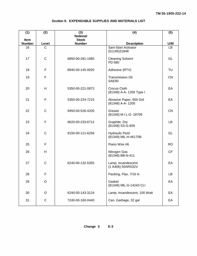
TM 55-1905-222-14
Section II. EXPENDABLE SUPPLIES AND MATERIALS LIST
(1) (2) (3) (4) (5)National
Item StockNumber Level Number Description U/M
16 C Sani-Start Activator LB(51195)31848
17 C 6850-00-281-1985 Cleaning Solvent GLPD 680
18 F 8940-00-145-0020 Adhesive (RTV) TU
19 F Transmission Oil CNSAE90
20 H 5350-00-221-0872 Crocus Cloth EA(81348) A-A- 1206 Type I
21 F 5350-00-224-7215 Abrasive Paper, 600 Grit EA(81348) A-A- 1200
22 C 9450-00-526-4205 Grease CN(81349) M I L-G- 18709
23 F 9620-00-233-6712 Graphite, Dry LB(81348) SS-G-659
24 C 9150-00-111-6256 Hydraulic Fluid GL(81349) MIL-H-46170B
25 F Piano Wire #6 RO
26 H Nitrogen Gas CF(81348) BB-N-411
27 C 6240-00-132-5355 Lamp, Incandescent EA(1 A406) 50ARS32V
28 F Packing, Flax, 7/16 in LB
29 O Gasket EA(81349) MIL-G-14243 CLI
30 O 6240-00-143-3124 Lamp, Incandescent, 100 Watt EA
31 C 7240-00-160-0440 Can, Garbage, 32 gal EA
Change 3 E-3
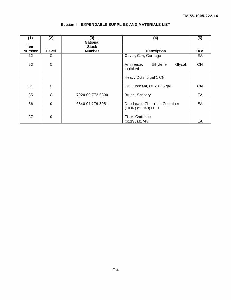
TM 55-1905-222-14
Section II. EXPENDABLE SUPPLIES AND MATERIALS LIST
(1) (2) (3) (4) (5)National
Item StockNumber Level Number Description U/M
32 C Cover, Can, Garbage EA
33 C Antifreeze, Ethylene Glycol,Inhibited
CN
Heavy Duty, 5 gal 1 CN
34 C Oil, Lubricant, OE-10, 5 gal CN
35 C 7920-00-772-6800 Brush, Sanitary EA
36 0 6840-01-279-3951 Deodorant, Chemical, Container EA(OLIN) (53048) HTH
37 0 Filter Cartridge(61195)31749 EA
E-4
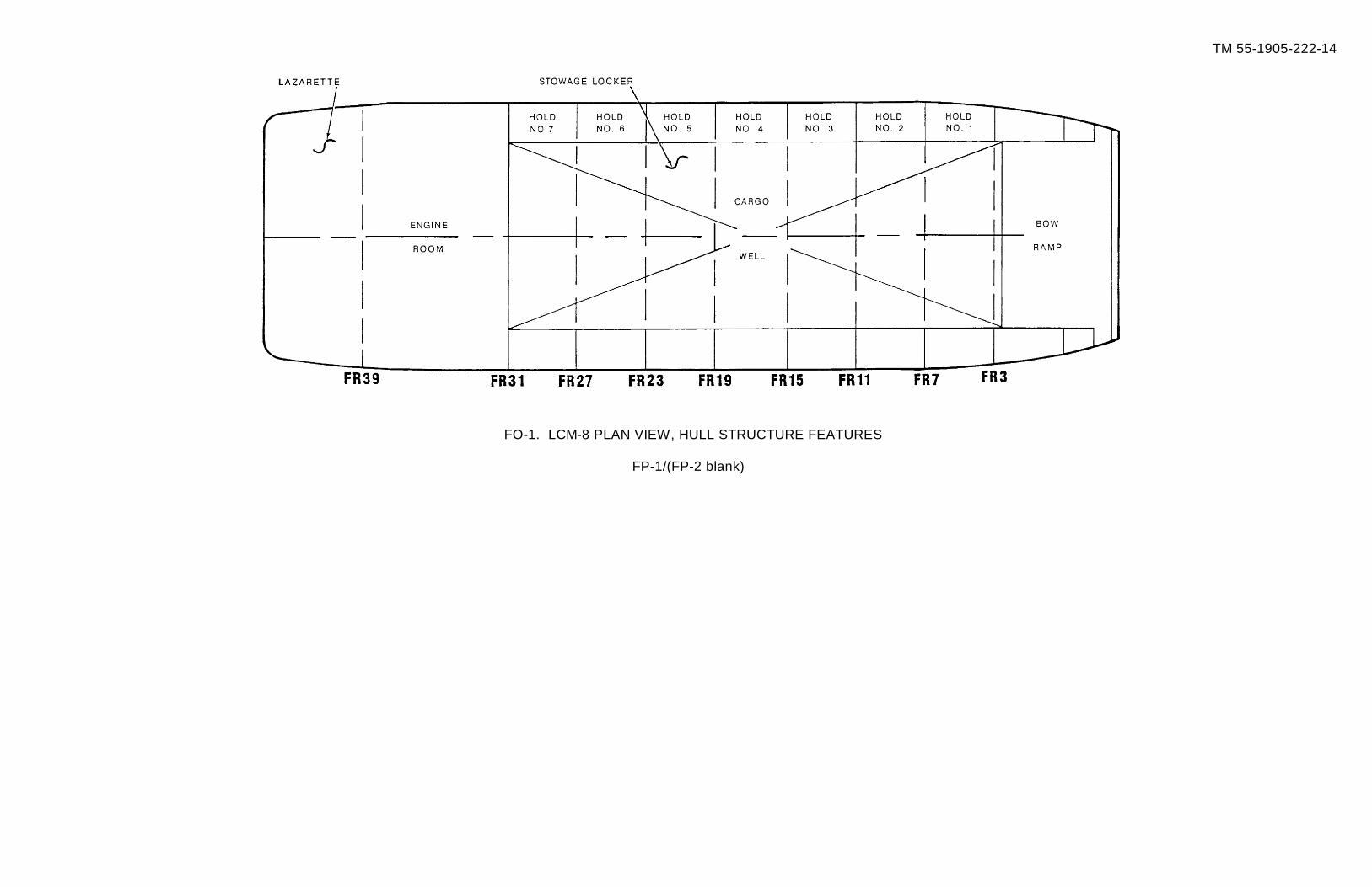
TM 55-1905-222-14
FO-1. LCM-8 PLAN VIEW, HULL STRUCTURE FEATURES
FP-1/(FP-2 blank)
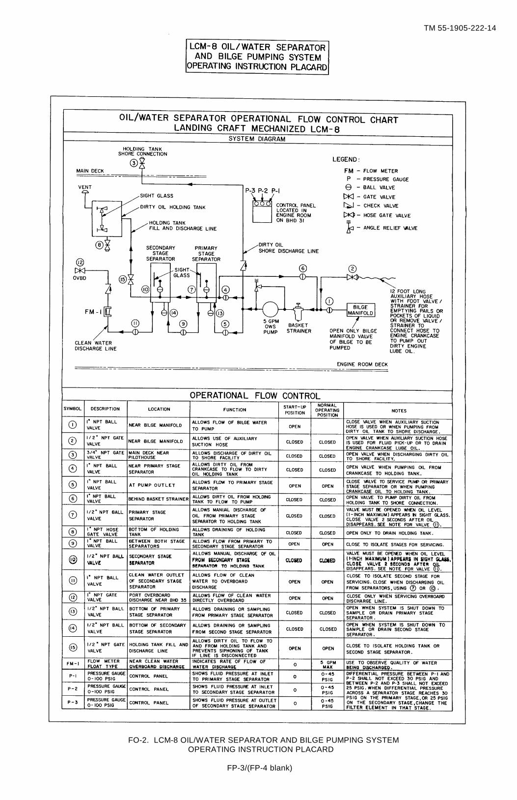
TM 55-1905-222-14
FO-2. LCM-8 OIL/WATER SEPARATOR AND BILGE PUMPING SYSTEMOPERATING INSTRUCTION PLACARD
FP-3/(FP-4 blank)
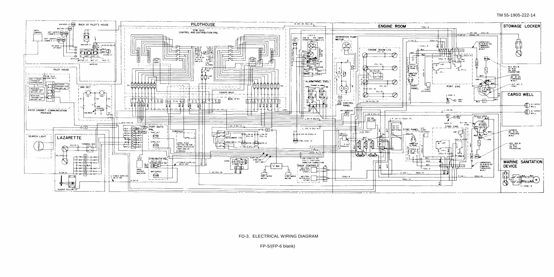
TM 55-1905-222-14
FO-3. ELECTRICAL WIRING DIAGRAM
FP-5/(FP-6 blank)
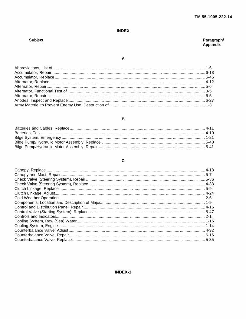
TM 55-1905-222-14
INDEX
Subject Paragraph/Appendix
A
Abbreviations, List of................................ ................................ ................................ ................................ ....1-6Accumulator, Repair................................ ................................ ................................ ................................ .....6-18Accumulator, Replace................................ ................................ ................................ ................................ ..5-45Alternator, Replace ................................ ................................ ................................ ................................ ......4-12Alternator, Repair................................ ................................ ................................ ................................ .........5-6Alternator, Functional Test of ................................ ................................ ................................ ....................... 3-5Alternator, Repair................................ ................................ ................................ ................................ .........6-5Anodes, Inspect and Replace................................ ................................ ................................ ....................... 6-27Army Materiel to Prevent Enemy Use, Destruction of ................................ ................................ .................. 1-3
B
Batteries and Cables, Replace................................ ................................ ................................ ..................... 4-11Batteries, Test................................ ................................ ................................ ................................ ..............4-10Bilge System, Emergency ................................ ................................ ................................ ............................ 1-21Bilge Pump/Hydraulic Motor Assembly, Replace . ................................ ................................ ........................ 5-40Bilge Pump/Hydraulic Motor Assembly, Repair ................................ ................................ ............................ 5-41
C
Canopy, Replace................................ ................................ ................................ ................................ ..........4-18Canopy and Mast, Repair................................ ................................ ................................ ............................. 5-7Check Valve (Steering System), Repair ................................ ................................ ................................ .......5-36Check Valve (Steering System), Replace................................ ................................ ................................ .....4-33Clutch Linkage, Replace ................................ ................................ ................................ .............................. 5-9Clutch Linkage, Adjust................................ ................................ ................................ ................................ ..4-24Cold Weather Operation ................................ ................................ ................................ .............................. 2-6Components, Location and Description of Major................................ ................................ ........................... 1-9Control and Distribution Panel, Repair................................ ................................ ................................ ..........4-16Control Valve (Starting System), Replace ................................ ................................ ................................ ....5-47Controls and Indicators................................ ................................ ................................ ................................ .2-1Cooling System, Raw (Sea) Water................................ ................................ ................................ ...............1-16Cooling System, Engine................................ ................................ ................................ ............................... 1-14Counterbalance Valve, Adjust................................ ................................ ................................ ...................... 4-32Counterbalance Valve, Repair................................ ................................ ................................ ...................... 6-16Counterbalance Valve, Replace................................ ................................ ................................ ................... 5-35
INDEX-1
TM 55-1905-222-14
INDEX (CONT)
Subject Paragraph/Appendix
D
Duplex Stainer (Sea Water System), Replace................................ ................................ .............................. 5-42Duplex Stainers (Sea Water System), Repair................................ ................................ ............................... 5-43
E
Electric Horn, Replace ................................ ................................ ................................ ................................ .4-9Electrical System ................................ ................................ ................................ ................................ ........1-22Emergency Procedures ................................ ................................ ................................ ............................... 2-9Engine Shutdown Controls (Air and Fuel), Replace................................ ................................ ...................... 4-25Engine/Transmission Instruments, Replace................................ ................................ ................................ ..5-10Equipment Data ................................ ................................ ................................ ................................ ..........1-10Equipment Characteristics, Capabilities and Features................................ ................................ .................. 1-8Exhaust Piping and Muffler, Replace/Repair ................................ ................................ ................................ 4-34Exhaust System................................ ................................ ................................ ................................ ...........1-15Expansion Tank, Replace ................................ ................................ ................................ ............................ 5-50Expansion Tank, Repair ................................. ................................ ................................ ............................. 5-51
F
Filter, Disinfection Unit and Retention Canisters, Replace................................ ................................ ............4-27Filters (Starting System), Replace ................................ ................................ ................................ ...............5-46Flow Divider, Replace ................................ ................................ ................................ ................................ .5-34Flow Divider, Repair ................................ ................................ ................................ ................................ ....6-15Foul Weather Operation................................ ................................ ................................ ............................... 2-8Fuel Strainer, Replace ................................ ................................ ................................ ................................ .3-15Fuel Strainer, Service ................................ ................................ ................................ ................................ ..3-14Fuel Filter/Water Separator, Service . ................................ ................................ ................................ ..........3-16Fuel Filter/Water Separator, Replace................................ ................................ ................................ ...........3-17Fuel System................................ ................................ ................................ ................................ .................1-13
G
General (Service Upon Receipt)................................ ................................ ................................ ................... 1-24Glossary ................................ ................................ ................................ ................................ ...................... 1-7
INDEX-2
TM 55-1905-222-14
INDEX (CONT)
Subject Paragraph/Appendix
H
Hand Pump (Starting System), Repair................................ ................................ ................................ ..........6-20Hand Pump (Starting System), Replace................................ ................................ ................................ .......5-49Hatches and Void Covers, Replace/Repair................................ ................................ ................................ ...5-13Helm Unit, Replace ................................ ................................ ................................ ................................ ......5-31Helm Unit, Repair................................ ................................ ................................ ................................ .........6-14Hoses and Fittings, Replace................................ ................................ ................................ ......................... 4-30Hot Weather Operation................................ ................................ ................................ ................................ 2-7Hull, Bitts, Chocks and Tiedowns, Replace/Repair................................ ................................ ....................... 5-12Hydraulic Gauges, Rudder Angle Indicator and Ammeter, Replace................................ .............................. 5-11
I
Inspecting and Servicing the LCM-8................................ ................................ ................................ .............1-25
K
Keel Cooler, Inspect, Service, Test, Replace and Repair................................ ................................ ..............6-26
Latch Mechanism, Replace................................ ................................ ................................ .......................... 5-26Lighting Fixtures and Switches, Replace/Repair................................ ................................ ........................... 4-17Lubrication Instructions, General................................ ................................ ................................ .................. 3-1
M
Maintenance Procedures, General................................ ................................ ................................ ...............4-6Maintenance Procedures, General................................ ................................ ................................ ...............3-3Maintenance Procedures, General................................ ................................ ................................ ...............5-5Maintenance Forms and Records ................................. ................................ ................................ ...............1-2Mast, Replace................................ ................................ ................................ ................................ ..............4-20MSD Pump/Motor Assembly, Repair ................................ ................................ ................................ ............4-29MSD Pump and Motor Assembly, Replace................................ ................................ ................................ ...4-28
INDEX-3
TM 55-1905-222-14
INDEX (CONT)
Subject Paragraph/Appendix
N
Navigation Light Bulb and Lens Housing, Replace................................ ................................ ....................... 3-4Navigation Light Fixtures and Switches, Replace................................ ................................ ......................... 4-7
O
Oil/Water Separator and Bilge Pumping System................................ ................................ .......................... 1-20Operating Procedure................................ ................................ ................................ ................................ ....2-4Operation of Auxiliary Equipment................................ ................................ ................................ .................2-5
P
Parts, Repair................................ ................................ ................................ ................................ ................6-3Parts, Repair................................ ................................ ................................ ................................ ................5-3Parts, Repair................................ ................................ ................................ ................................ ................4-3Pre-operating Procedures................................ ................................ ................................ ............................. 2-3Preventive Maintenance Checks and Services Procedures................................ ................................ ..........4-4Preventive Maintenance................................ ................................ ................................ ............................... 2-2Propeller and Propeller Shaft, Repair................................ ................................ ................................ ...........6-23Propeller and Propeller Shaft, Inspect and Service................................ ................................ ....................... 6-21Propeller and Propeller Shaft, Align ................................ ................................ ................................ .............6-24Propeller and Propeller Shaft, Replace................................ ................................ ................................ .........6-22Propulsion Control Head, Replace ................................. ................................ ................................ ..............4-22Propulsion System................................ ................................ ................................ ................................ .......1-12Pump, Repair Steering................................ ................................ ................................ ................................ .6-12
Q
Quality Assurance/Quality Control (QA/QC) ................................ ................................ ................................ .1-5
R
Ramp Hoist Hand Pump, Repair ................................ ................................ ................................ .................. 6-8Ramp Hoist Control Valve, Repair................................ ................................ ................................ ................6-7Ramp Winch, Replace ................................ ................................ ................................ ................................ .5-24Ramp System Reservoir, Strainers and Filter, Inspect................................ ................................ .................. 3-8Ramp Winch Hydraulic Motor, Repair ................................ ................................ ................................ ..........5-23Ramp Hoist Hydraulic Check Valve, Repair ................................ ................................ ................................ .5-19Ramp System Reservoir, Strainers, and Filters, Service ................................ ................................ ..............3-9Ramp Hydraulic System................................ ................................ ................................ ............................... 1-19
INDEX-4
TM 55-1905-222-14
INDEX (CONT)
Subject Paragraph/Appendix
R
Ramp Winch Hydraulic Motor, Replace................................ ................................ ................................ ........5-22Ramp Winch, Repair................................ ................................ ................................ ................................ ....6-10Ramp Seal, Replace ................................ ................................ ................................ ................................ ....5-28Ramp Locking Hydraulic Cylinders, Replace................................ ................................ ................................ 5-21Ramp Hoist Hydraulic Pump, Replace................................ ................................ ................................ ..........5-16Ramp Hoist Hand Pump, Replace ................................ ................................ ................................ ...............5-20Ramp Hoist Control Valve, Replace . ................................ ................................ ................................ ...........5-17Ramp and Hinge Pins, Replace................................ ................................ ................................ .................... 5-25Ramp Cables, Sheaves and Chains, Replace................................ ................................ .............................. 5-27Ramp Hoist Hydraulic Check Valve, Replace................................ ................................ ............................... 5-18Ramp Hoist Hydraulic Pump, Repair ................................ ................................ ................................ ............6-6Ramp Sheaves and Latch Mechanism, Repair................................ ................................ ............................. 6-11Ramp Locking Hydraulic Cylinder, Repair ................................ ................................ ................................ ....6-9Recharging Pump, Replace................................ ................................ ................................ .......................... 5-44Recharging Pump, Repair................................ ................................ ................................ ............................ 6-17Relief Valve, Repair ................................ ................................ ................................ ................................ .....5-33Relief Valve (Steering System), Replace................................ ................................ ................................ ......5-32Reporting Equipment Improvement Recommendations (EIRs) ................................ ................................ ....1-4Rudder, Repair ................................ ................................ ................................ ................................ ............5-38Rudder Angle Transmitter, Replace................................ ................................ ................................ ..............5-39Rudder and Tiller, Service of ................................ ................................ ................................ ....................... 4-35Rudder, Replace ................................. ................................ ................................ ................................ ........5-37
S
Safety, Care and Handling ................................ ................................ ................................ .......................... 1-11Sanitation System, Service ................................ ................................ ................................ .......................... 3-7Sanitation System, Inspect ................................ ................................ ................................ .......................... 3-6Sanitation System, Marine . ................................ ................................ ................................ ......................... 1-23Scope ................................ ................................ ................................ ................................ .......................... 1-1Sea Water Strainers, Service ................................ ................................ ................................ ...................... 3-12Searchlight Bulb, Reflector Glass and Fixture, Replace................................ ................................ ................4-8Service Level Indicator................................ ................................ ................................ ................................ .4-31Special Tools, TMDE and Support Equipment................................ ................................ .............................. 4-2Special Tools, TMDE and Support Equipment ................................. ................................ ............................ 5-2Special Tools, TMDE and Support Equipment................................ ................................ .............................. 6-2Stanchions and Lifelines, Replace/Repair................................ ................................ ................................ ....5-14Starting System Reservoir and Filters, Service ................................ ................................ ............................ 3-13Starting System, Hydraulic ................................ ................................ ................................ ........................... 1-17
INDEX-5
TM 55-1905-222-14
INDEX (CONT)
Subject Paragraph/Appendix
Starting Motor, Replace................................ ................................ ................................ ................................ 5-48Starting Motor, Repair ................................ ................................ ................................ ................................ .6-19Steering System Reservoir, Strainers and Filters, Service................................ ................................ ............3-11Steering System, Hydraulic ................................ ................................ ................................ .......................... 1-18Steering System Reservoir, Strainers and Filter, Inspect................................ ................................ ..............3-10Steering Pump, Replace ................................ ................................ ................................ .............................. 5-29Steering Cylinders, Replace ................................. ................................ ................................ ....................... 5-30Steering Cylinders, Repair................................ ................................ ................................ ............................ 6-13Stuffing Box, Adjust ................................ ................................ ................................ ................................ .....3-18Stuffing Box, Repair................................ ................................ ................................ ................................ .....6-25
T
Throttle Linkage, Adjust ................................ ................................ ................................ ............................... 4-23Throttle Linkage, Replace ................................ ................................ ................................ ............................ 5-8Tools and Equipment, Common................................ ................................ ................................ ................... 4-1Tools and Equipment, Common................................ ................................ ................................ ................... 6-1Tools and Equipment, Common................................ ................................ ................................ ................... 5-1Treatment Tank, Replace................................ ................................ ................................ ............................. 4-26Troubleshooting Procedures................................ ................................ ................................ ......................... 3-2Troubleshooting Procedures ................................ ................................ ................................ ........................ 4-5Troubleshooting Procedures................................ ................................ ................................ ......................... 5-4Troubleshooting Procedures................................ ................................ ................................ ......................... 6-4
U
Used Equipment................................ ................................ ................................ ................................ ...........1-26
V
Voids and Compartments, Repair................................ ................................ ................................ .................5-15Voltage Regulator, Adjust ................................ ................................ ................................ ............................ 4-13Voltage Regulator, Replace................................ ................................ ................................ .......................... 4-14Voltage Protector, Replace................................ ................................ ................................ ........................... 4-15
W
Window, Replace................................ ................................ ................................ ................................ .........4-19Windshield Wipers and Wiper Motor, Replace................................ ................................ ............................. 4-21
INDEX-6
TM 55-1905-222-14
By Order of the Secretary of the Army
CARL E. VUONOGeneral, United States Army
Chief of Staff
Official
WILLIAM J. MEEHAN, IIBrigadier General, United States Army
The Adjutant General
DISTRIBUTIONTo be distributed in accordance with DA Form 12-25A, Operator, Unit Intermediate Direct Support and Intermediate
General Support Maintenance requirements for Landing Craft, Mechanized, Steel design LCM-8, Model 1, Mark VII, 74Ft
*U S GOVERNMENT PRINTING OFFICE 1994 - 300-421/82732
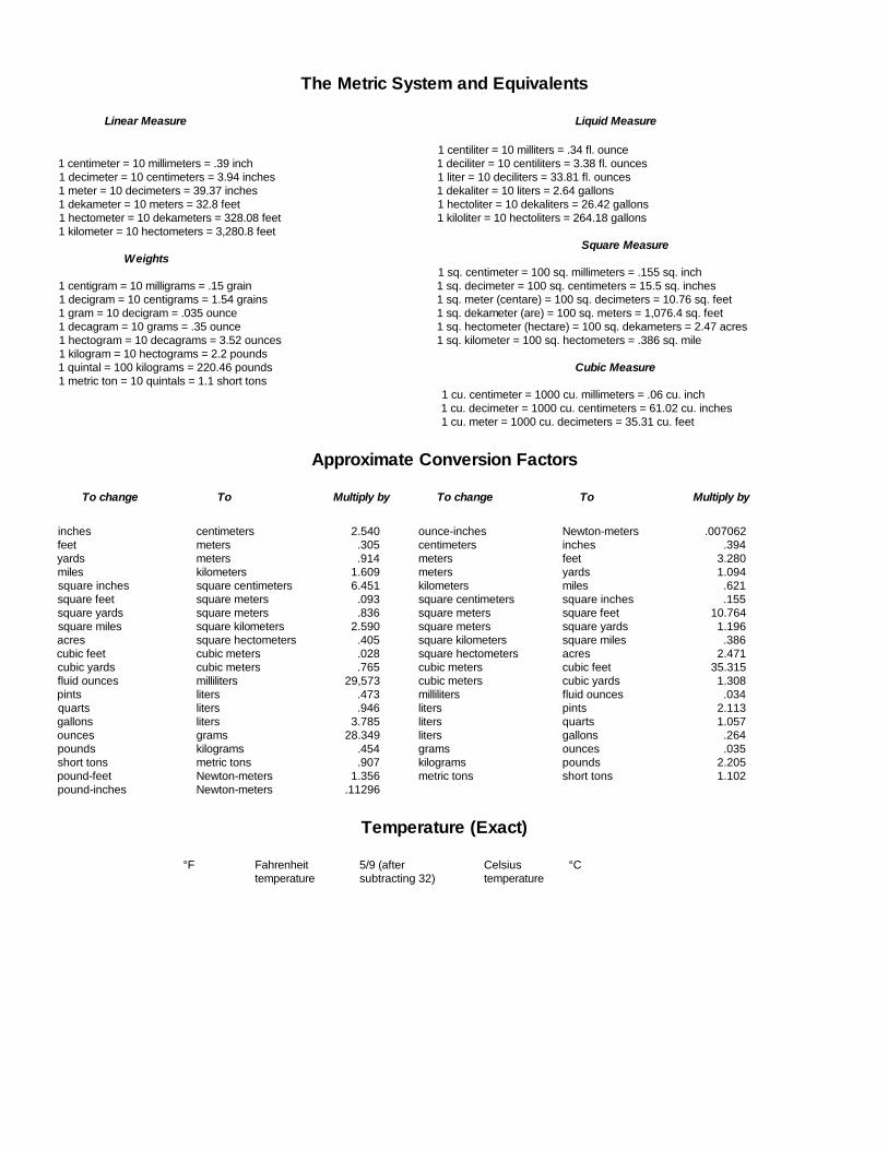
The Metric System and Equivalents
Linear Measure Liquid Measure
1 centiliter = 10 milliters = .34 fl. ounce1 centimeter = 10 millimeters = .39 inch 1 deciliter = 10 centiliters = 3.38 fl. ounces1 decimeter = 10 centimeters = 3.94 inches 1 liter = 10 deciliters = 33.81 fl. ounces1 meter = 10 decimeters = 39.37 inches 1 dekaliter = 10 liters = 2.64 gallons1 dekameter = 10 meters = 32.8 feet 1 hectoliter = 10 dekaliters = 26.42 gallons1 hectometer = 10 dekameters = 328.08 feet 1 kiloliter = 10 hectoliters = 264.18 gallons1 kilometer = 10 hectometers = 3,280.8 feet
Square MeasureWeights
1 sq. centimeter = 100 sq. millimeters = .155 sq. inch1 centigram = 10 milligrams = .15 grain 1 sq. decimeter = 100 sq. centimeters = 15.5 sq. inches1 decigram = 10 centigrams = 1.54 grains 1 sq. meter (centare) = 100 sq. decimeters = 10.76 sq. feet1 gram = 10 decigram = .035 ounce 1 sq. dekameter (are) = 100 sq. meters = 1,076.4 sq. feet1 decagram = 10 grams = .35 ounce 1 sq. hectometer (hectare) = 100 sq. dekameters = 2.47 acres1 hectogram = 10 decagrams = 3.52 ounces 1 sq. kilometer = 100 sq. hectometers = .386 sq. mile1 kilogram = 10 hectograms = 2.2 pounds1 quintal = 100 kilograms = 220.46 pounds Cubic Measure1 metric ton = 10 quintals = 1.1 short tons
1 cu. centimeter = 1000 cu. millimeters = .06 cu. inch1 cu. decimeter = 1000 cu. centimeters = 61.02 cu. inches1 cu. meter = 1000 cu. decimeters = 35.31 cu. feet
Approximate Conversion Factors
To change To Multiply by To change To Multiply by
inches centimeters 2.540 ounce-inches Newton-meters .007062feet meters .305 centimeters inches .394yards meters .914 meters feet 3.280miles kilometers 1.609 meters yards 1.094square inches square centimeters 6.451 kilometers miles .621square feet square meters .093 square centimeters square inches .155square yards square meters .836 square meters square feet 10.764square miles square kilometers 2.590 square meters square yards 1.196acres square hectometers .405 square kilometers square miles .386cubic feet cubic meters .028 square hectometers acres 2.471cubic yards cubic meters .765 cubic meters cubic feet 35.315fluid ounces milliliters 29,573 cubic meters cubic yards 1.308pints liters .473 milliliters fluid ounces .034quarts liters .946 liters pints 2.113gallons liters 3.785 liters quarts 1.057ounces grams 28.349 liters gallons .264pounds kilograms .454 grams ounces .035short tons metric tons .907 kilograms pounds 2.205pound-feet Newton-meters 1.356 metric tons short tons 1.102pound-inches Newton-meters .11296
Temperature (Exact)
°F Fahrenheit 5/9 (after Celsius °Ctemperature subtracting 32) temperature

PIN: 066281-006

This fine document...
Was brought to you by me:
Liberated Manuals -- free army and government manuals
Why do I do it? I am tired of sleazy CD-ROM sellers, who take publicly available information, slap “watermarks” and other junk on it, and sell it. Those masters of search engine manipulation make sure that their sites that sell free information, come up first in search engines. They did not create it... They did not even scan it... Why should they get your money? Why are not letting you give those free manuals to your friends?
I am setting this document FREE. This document was made by the US Government and is NOT protected by Copyright. Feel free to share, republish, sell and so on.
I am not asking you for donations, fees or handouts. If you can, please provide a link to liberatedmanuals.com, so that free manuals come up first in search engines:
<A HREF=http://www.liberatedmanuals.com/>Free Military and Government Manuals</A>
– SincerelyIgor Chudovhttp://igor.chudov.com/
– Chicago Machinery Movers