Embed Size (px)
Citation preview
ARMY TM 9-6150-226-13
AIR FORCE TO 35CA6-1-261TECHNICAL MANUAL
OPERATOR AND FIELD MAINTENANCE MANUAL FOR
DISTRIBUTION ILLUMINATIONSYSTEMS, ELECTRICAL (DISE) AND
POWER DISTRIBUTION ILLUMINATION SYSTEMS, ELECTRICAL (PDISE)CONSISTING OF
ELECTRICAL FEEDER SYSTEM M200, M200 A/P
(6150-01-208-9755), (6150-01-308-5672)
ELECTRICAL FEEDER SYSTEM M100, M100 A/P
(6150-01-208-9754), (6150-01-308-5671)
ELECTRICAL DISTRIBUTION SYSTEM M40, M40 A/P
(6150-01-208-9753), (6150-01-307-9446)
ELECTRICAL DISTRIBUTION SYSTEM M60, M60 A/P
(6150-01-208-9752), (6150-01-307-9445)
ELECTRICAL UTILITY ASSEMBLY M46 (6150-01-208-9751)
DISTRIBUTION STATEMENT A. Approved for public release; distribution is unlimited. This manual supercedes TM 9-6150-226-13, dated 30 May 1991.
HEADQUARTERS, DEPARTMENT OF THE ARMY 1 NOVEMBER 2008


ARMY TM 9-6150-226-13 AIR FORCE TO 35CA6-1-261
WARNING SUMMARY
This warning summary contains general safety warnings and hazardous materials warnings that must be understood and applied during operation and maintenance of this equipment. Failure to observe these precautions could result in serious injury or death to personnel. Also included are explanations of safety and hazardous material icons used within the technical manual.
FIRST AID
For first aid, refer to FM 4-25.11.
a
ARMY TM 9-6150-226-13
AIR FORCE TO 35CA6-1-261
WARNING SUMMARY (Continued) SAFETY AND HAZARDOUS MATERIAL
This manual describes physical and chemical processes that may require the use of chemicals, solvents, paints, or other commercially available material. Users of the manual should obtain the material safety data sheets (Occupational Safety and Health Act (OSHA) Form 20 or equivalent) from the manufacturers or suppliers of materials to be used. Users must be completely familiar with manufacturer/supplier information and adhere to their procedures, recommendations, warnings, and cautions for safe use, handling, storage, and disposal of these materials.
EXPLANATION OF SAFETY WARNING ICONS
ELECTRICAL - electrical wire to hand with electricity symbol running through hand shows that shock hazard exists.
HOT AREA - hand over object radiating heat shows that part or area is hot and can burn.
EAR PROTECTION - headphones over ears shows that noise level will harm ears.
HEAVY OBJECT - human figure stooping over heavy object shows physical injury potential from improper lifting technique or failure to share lifting task with other persons.
HEAVY PARTS - hand with heavy object on top shows that heavy parts can crush and harm if dropped.
HEAVY PARTS - foot with heavy object on top shows that heavy parts can crush and harm if dropped
b
ARMY TM 9-6150-226-13 AIR FORCE TO 35CA6-1-261
WARNING SUMMARY (Continued)
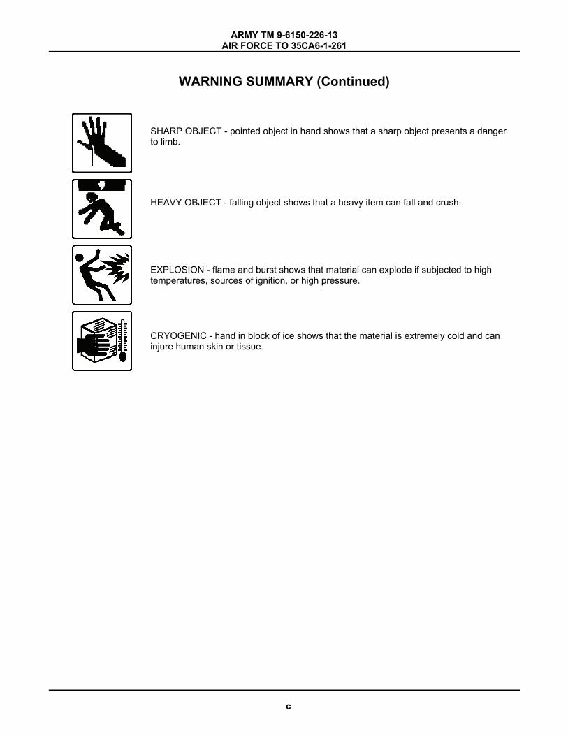
SHARP OBJECT - pointed object in hand shows that a sharp object presents a danger to limb.
HEAVY OBJECT - falling object shows that a heavy item can fall and crush.
EXPLOSION - flame and burst shows that material can explode if subjected to high temperatures, sources of ignition, or high pressure.
CRYOGENIC - hand in block of ice shows that the material is extremely cold and can injure human skin or tissue.
c

ARMY TM 9-6150-226-13 AIR FORCE TO 35CA6-1-261
WARNING SUMMARY (Continued) GENERAL SAFETY WARNINGS DESCRIPTION
WARNING
Metal jewelry will conduct electricity. Remove all jewelry when working on equipment. Failure to comply can cause injury or death to personnel by electrocution.
WARNING
High voltage is present when in operation. Make sure system is completely shut down and free of any power source before attempting any repair or maintenance on the unit. Failure to comply can cause injury or death to personnel.
WARNING
High voltage is present in the DISE and PDISE systems. Do not submerge cable connections in water. Death or serious injury may result.
WARNING
GROUND FAULT CIRCUIT BREAKERS are used in this equipment. DEATH ON CONTACT may result if personnel fail to observe safety precautions. Some of the 20-amp circuits on the DISE feeder and distribution centers use ground fault circuit breakers. The neutral and ground of some generator sets must be electrically connected with 6-gage wire for the ground fault circuit breakers to function properly. Failure to electrically connect the ground and neutral lugs may result in death or severe injury.
WARNING
HIGH VOLTAGE is used in the operation of this equipment. DEATH ON CONTACT may result if personnel fail to observe safety precautions. Never work on electrical equipment unless there is another person nearby who is familiar with the operation and hazards of the equipment and who is competent in administering first aid. When the technician is aided by operators, he must warn them about dangerous areas. The power supply to the equipment must be shut off before beginning to work on the equipment. The power source must be grounded at all times when equipment is in use or being worked on. Be careful not to contact high-voltage connections of 120/208 volts when installing or operating this equipment.
d
ARMY TM 9-6150-226-13 AIR FORCE TO 35CA6-1-261
WARNING SUMMARY (Continued)
WARNING
High voltage is present in this system. DISE/PDISE supports equipment using 120/208 VAC. Do not rely on the color of the wire insulation for phase color-coding. The insulation on the wires inside the cable jacket may vary, depending on supplier. Wires will be color coded to designate the phases. If the wire color coding cannot be determined, notify next higher level of maintenance to perform continuity test. Perform a continuity test to verify correct phase designations in accordance with identified color. Failure to recognize this may result in death or serious personal injury.
WARNING
High voltage is present in all the DISE and PDISE systems. Disconnect power from generator before servicing. Death or serious injury may result.
WARNING
Components can be extremely heavy and require an assistant and/or a lifting device (forklift, overhead lifting device) with sufficient capacity. Failure to comply can cause serious injury or death to personnel.
WARNING
Do not allow anyone under equipment suspended from a lifting device. Do not allow the unit to swing while suspended from a lifting device. Lack of attention or being in an improper position during lifting operations can result in serious injury or death to personnel and damage to the equipment.
e
ARMY TM 9-6150-226-13
AIR FORCE TO 35CA6-1-261
WARNING SUMMARY (Continued)
HAZARDOUS WARNINGS DESCRIPTION-
WARNING
FLAMMABLE solvents and cleaning materials are used in the cleaning and maintenance of this equipment. Do not use flammables in areas where open flame or other ignition sources are present. Be sure that adequate ventilation is provided. Avoid inhalation of flammable liquids. Properly dispose of rags and other materials contaminated with flammable liquids. Have flame extinguishing equipment readily available when using flammable materials.
WARNING
Rivets can shatter during removal or installation and cause serious personal injury or death.
WARNING
In extreme cold weather, skin can stick to metal. Avoid contacting metal items with bare skin in extreme cold weather. Failure to comply can cause injury or death to personnel.
f
ARMY TM 9-6150-226-13 AIR FORCE TO 35CA6-1-261
CHANGE HEADQUARTERS, NO. 1 DEPARTMENT OF THE ARMY WASHINGTON, DC, 1 JANUARY 2010
TECHNICAL MANUAL
OPERATOR AND FIELD MAINTENANCE MANUAL FOR
DISTRIBUTION ILLUMINATION SYSTEMS, ELECTRICAL (DISE) AND POWER DISTRIBUTION ILLUMINATION SYSTEMS, ELECTRICAL (PDISE)
CONSISTING OF ELECTRICAL FEEDER SYSTEM M200, M200 A/P
(6150-01-208-9755), (6150-01-308-5672)
ELECTRICAL FEEDER SYSTEM M100, M100 A/P (6150-01-208-9754), (6150-01-308-5671)
ELECTRICAL DISTRIBUTION SYSTEM M40, M40 A/P
(6150-01-208-9753), (6150-01-307-9446)
ELECTRICAL DISTRIBUTION SYSTEM M60, M60 A/P (6150-01-208-9752), (6150-01-307-9445)
ELECTRICAL UTILITY ASSEMBLY, M46
(6150-01-208-9751)
DISTRIBUTION STATEMENT A: Approved for public release; distribution is unlimited.
TM 9-6150-226-13, dated 1 January 2010, is updated as follows:
1. File this sheet in front of the manual for reference.
2. This change is a result of new preventative maintenance checks and service procedures and new expendable/durable supplies and materials.
3. New or updated text is indicated by a vertical bar in the outer margin of the page. 4. Added illustrations are indicated by a vertical bar adjacent to the figure number. Changed illustrations are indicated by a miniature pointing hand adjacent to the updated area and a vertical bar adjacent to the figure number.
5. If manually incorporating this change package:
a. Remove and dispose of the last page with the Publication Identification Number (PIN) on it. The PIN format is six numbers, a dash, and then three numbers. For example, 123456-789. This page should be blank on its other side.
b. If there is a page that is blank on both sides preceding the page with the PIN on it, remove and dispose of it also.
6. Remove old pages and insert new pages as indicated below:
Remove Pages Insert Pages A/B Blank A/B Blank
7. Replace the following work packages with their revised version.
Work Package Number WP 0001 WP 0027 WP 0029 WP 0031 WP 0036 WP 0039

By Order of the Secretary of the Air For ce:
By Order of the Secretary of the Army:
GEORGE W. CASEY, JR General, United States Army
Chief of Sta�
0934101
J OY C E E. MORROW Adminis trative Assistant to the
Secretary of the Army
O�cial:
NORTON A . SCHWARTZ General, USAF Chief of Staff
Official:
Army Distribution: To be distributed in accordance with the initial distribution number (IDN) 255782 requirements for TM 9-6150-226-13.
TM 9-6150-226-13
DONALD J. HOFFMAN General, United States Air Force Commander, AFMC


ARMY TM 9-6150-226-13
AIR FORCE TO 35CA6-1-261
LIST OF EFFECTIVE PAGES/WORK PACKAGES
NOTE: * Zero in the “Change No.” column indicates an original page or work package.
Date of issue for original manual is:
Original ... 1 November 2008
Change 1... 1 January 2010
TOTAL NUMBER OF PAGES FOR FRONT AND REAR MATTER IS 36 AND TOTAL NUMBER OF WORK PACKAGES IS 40, CONSISTING OF THE FOLLOWING:
Page/WP No. *Change No. Page/WP No. *Change No.
Front Cover 0 Warning summary (6 pgs) 0 A 1 i-x 0 Chp 1 Title page 0 WP 0001 (22 pgs) 1 WP 0002 (22 pgs) 0 Chp 2 Title page 0 WP 0003 (14 pgs) 0 WP 0004 (4 pg) 0 Chp 3 Title page 0 WP 0005 (2 pgs) 0 WP 0006 (2 pgs) 0 Chp 4 Title page 0 WP 0007 (2 pg) 0 WP 0008 (6 pgs) 0 Chp 5 Title page 0 WP 0009 (2 pg) 0 WP 0010 (4 pgs) 0 Chp 6 Title page 0 WP 0011 (2 pg) 0
WP 0012 (2 pgs) 0 WP 0013 (2 pg) 0 WP 0014 (2 pgs) 0 WP 0015 (2 pgs) 0 WP 0016 (2 pgs) 0 WP 0017 (4 pgs) 0 WP 0018 (4 pgs) 0 WP 0019 (6 pgs) 0 WP 0020 (10 pgs) 0 WP 0021 (4 pgs) 0 WP 0022 (2 pgs) 0 WP 0023 (2 pgs) 0 WP 0024 (4 pgs) 0 WP 0025 (4 pgs) 0 WP 0026 (4 pgs) 0 WP 0027 (4 pgs) 1 WP 0028 (2 pgs) 0 Chp 7 Title page 0 WP 0029 (12 pgs) 1 WP 0030 (2 pgs) 0 WP 0031 (18 pgs) 1
Chp 8 Title Page 0 WP 0032 (2 pgs) 0 WP 0033 (2 pgs) 0 WP 0034 (4 pgs) 0 WP 0035 (6 pgs) 0 WP 0036 (12 pgs) 1 WP 0037 (2 pgs) 0 WP 0038 (2 pgs) 0 WP 0039 (92 pgs) 1 WP 0040 (2 pgs) 0
A/B Blank Change 1

ARMY TM 9-6150-226-13
AIR FORCE TO 35CA6-1-261
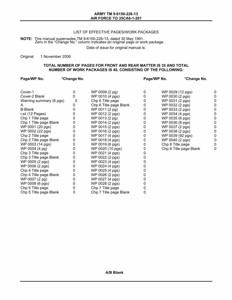
LIST OF EFFECTIVE PAGES/WORK PACKAGES
NOTE: This manual supercedes TM 9-6150-226-13, dated 30 May 1991.
Date of issue for original manual is:
Original 1 November 2008
TOTAL NUMBER OF PAGES FOR FRONT AND REAR MATTER IS 35 AND TOTAL NUMBER OF WORK PACKAGES IS 40, CONSISTING OF THE FOLLOWING:
Page/WP No. *Change No. Page/WP No. *Change No.
Cover-1 0 Cover-2 Blank 0 Warning summary (6 pgs) 0 A 0 B-Blank 0 i-xii (12 Pages) 0Chp 1 Title page 0Chp 1 Title page Blank 0 WP 0001 (20 pgs) 0WP 0002 (22 pgs) 0Chp 2 Title page 0Chp 2 Title page Blank 0 WP 0003 (14 pgs) 0WP 0004 (4 pg) 0Chp 3 Title page 0Chp 3 Title page Blank 0 WP 0005 (2 pgs) 0WP 0006 (2 pgs) 0Chp 4 Title page 0Chp 4 Title page Blank 0 WP 0007 (2 pg) 0WP 0008 (6 pgs) 0Chp 5 Title page 0Chp 5 Title page Blank 0
WP 0009 (2 pg) 0WP 0010 (4 pgs) 0Chp 6 Title page 0Chp 6 Title page Blank 0 WP 0011 (2 pg) 0WP 0012 (2 pgs) 0WP 0013 (2 pg) 0WP 0014 (2 pgs) 0WP 0015 (2 pgs) 0WP 0016 (2 pgs) 0WP 0017 (4 pgs) 0WP 0018 (4 pgs) 0WP 0019 (6 pgs) 0WP 0020 (10 pgs) 0WP 0021 (4 pgs) 0WP 0022 (2 pgs) 0WP 0023 (4 pgs) 0WP 0024 (4 pgs) 0WP 0025 (4 pgs) 0WP 0026 (2 pgs) 0WP 0027 (4 pgs) 0WP 0028 (2 pgs) 0Chp 7 Title page 0Chp 7 Title page Blank 0
WP 0029 (12 pgs) 0WP 0030 (2 pgs) 0WP 0031 (2 pgs) 0WP 0032 (2 pgs) 0WP 0033 (2 pgs) 0WP 0034 (4 pgs) 0WP 0035 (6 pgs) 0WP 0036 (8 pgs) 0WP 0037 (2 pgs) 0WP 0038 (2 pgs) 0WP 0039 (92 pgs) 0WP 0040 (2 pgs) 0 Chp 8 Title page 0 Chp 8 Title page Blank 0
A/B Blank
Zero in the “Change No.” column indicates an original page or work package.


ARMY TM 9-6150-226-13 AIR FORCE TO 35CA6-1-261
HEADQUARTERS
DEPARTMENT OF THE ARMY
WASHINGTON D.C., 1 Nov 2008
TECHNICAL MANUAL OPERATOR AND FIELD MAINTENANCE MANUAL
FOR DISTRIBUTION ILLUMINATION
SYSTEMS, ELECTRICAL (DISE) ANDPOWER DISTRIBUTION ILLUMINATION SYSTEMS, ELECTRICAL (PDISE)
CONSISTING OF
ELECTRICAL FEEDER SYSTEM M200, M200 A/P
(6150-01-208-9755), (6150-01-308-5672)
ELECTRICAL FEEDER SYSTEM M100, M100 A/P
(6150-01-208-9754), (6150-01-308-5671)
ELECTRICAL DISTRIBUTION SYSTEM M40, M40 A/P
(6150-01-208-9753), (6150-01-307-9446)
ELECTRICAL DISTRIBUTION SYSTEM M60, M60 A/P
(6150-01-208-9752), (6150-01-307-9445)
ELECTRICAL UTILITY ASSEMBLY M46 (6150-01-208-9751)
DISTRIBUTION STATEMENT A. Approved for public release; distribution is unlimited. This manual supercedes TM 9-6150-226-13, dated 30 May 1991.
REPORTING ERRORS AND RECOMMENDING IMPROVEMENTS
You can help improve this manual. If you find any mistakes or if you know of a way to improve the procedures, please let us know. Mail your letter or DA Form 2028 (Recommended Changes to Publications and Blank Forms), located in the back of this manual directly to: Commander, U.S. Army Communications Electronics Life Cycle Management Command (C-E LCMC) and Fort Monmouth, ATTN: AMSEL-LC-LEO-E-ED, Fort Monmouth, NJ 07703-5006. You may also send in your recommended changes via electronic mail or by fax. Our fax number is 732-532-1556, DSN 992-1556. Our e-mail address is [email protected]. Our online web address for entering and submitting DA Form 2028s is http://edm.monmouth.army.mil/pubs/2028.html
(F) Air Force - By Air Force AFTO Form 22 (Technical Manual (TM) Change Recommendation and Reply) in accordance with paragraph 6-5, Section VI, TO 00-5-1 directly to prime ALC/MST.
i
ARMY TM 9-6150-226-13 AIR FORCE TO 35CA6-1-261
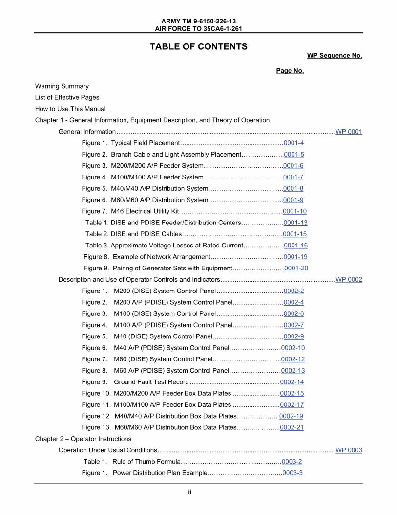
TABLE OF CONTENTS WP Sequence No.
Page No.
Warning Summary
List of Effective Pages
How to Use This Manual
Chapter 1 - General Information, Equipment Description, and Theory of Operation
General Information..........................................................................................................................WP 0001
Figure 1. Typical Field Placement .........................................................0001-4
Figure 2. Branch Cable and Light Assembly Placement………………..0001-5
Figure 3. M200/M200 A/P Feeder System……………………………….0001-6
Figure 4. M100/M100 A/P Feeder System……………………………….0001-7
Figure 5. M40/M40 A/P Distribution System……………………………..0001-8
Figure 6. M60/M60 A/P Distribution System……………………………..0001-9
Figure 7. M46 Electrical Utility Kit…………………………………………0001-10
Table 1. DISE and PDISE Feeder/Distribution Centers………………..0001-13
Table 2. DISE and PDISE Cables………………………………………..0001-15
Table 3. Approximate Voltage Losses at Rated Current……………….0001-16
Figure 8. Example of Network Arrangement…………………………….0001-19
Figure 9. Pairing of Generator Sets with Equipment……………………0001-20
Description and Use of Operator Controls and Indicators................................................................WP 0002
Figure 1. M200 (DISE) System Control Panel .....................................0002-2
Figure 2. M200 A/P (PDISE) System Control Panel............................0002-4
Figure 3. M100 (DISE) System Control Panel .....................................0002-6
Figure 4. M100 A/P (PDISE) System Control Panel............................0002-7
Figure 5. M40 (DISE) System Control Panel .......................................0002-9
Figure 6. M40 A/P (PDISE) System Control Panel……………………0002-10
Figure 7. M60 (DISE) System Control Panel…………………………..0002-12
Figure 8. M60 A/P (PDISE) System Control Panel……………………0002-13
Figure 9. Ground Fault Test Record ..................................................0002-14
Figure 10. M200/M200 A/P Feeder Box Data Plates ..........................0002-15
Figure 11. M100/M100 A/P Feeder Box Data Plates ..........................0002-17
Figure 12. M40/M40 A/P Distribution Box Data Plates………………. 0002-19
Figure 13. M60/M60 A/P Distribution Box Data Plates……….. ……...0002-21
Chapter 2 – Operator Instructions
Operation Under Usual Conditions...................................................................................................WP 0003
Table 1. Rule of Thumb Formula………………………………………..0003-2
Figure 1. Power Distribution Plan Example……………………………..0003-3
ii

ARMY TM 9-6150-226-13 AIR FORCE TO 35CA6-1-261
TABLE OF CONTENTS (CONTINUED)
WP Sequence No.
Page No.
Figure 2. Power Distribution Layout Example…………………………..0003-5
Figure 3. Load Assignments Example………………………………….. 0003-6
Table 2. Connector to Phase Links…………………………………….. 0003-7
Table 3. Feeder/Distribution Center Output Connector Loads…… 0003-8
Figure 4. Universal Adapter…………………………………………… 0003-11
Operation Under Unusual Conditions...............................................................................................WP 0004
Chapter 3 –Operator Troubleshooting Procedures
Operator Troubleshooting Index.......................................................................................................WP 0005
Operator Troubleshooting............................................................................................... .................WP 0006
Chapter 4 – Operator Maintenance Procedures
Preventive Maintenance Checks and Services (PMCS) Introduction ..............................................WP 0007
Preventive Maintenance Checks and Services (PMCS) ..................................................................WP 0008
Table 1. Operator Preventive Maintenance Checks and Services (PMCS).............................................. ………….0008-1
Chapter 5 –Field Level Troubleshooting Procedures
Field Troubleshooting Introduction ................................................................................. .................WP 0009
Table 1. Troubleshooting Index……………………………………………0009-2
Field Troubleshooting Procedures....................................................................................................WP 0010
Chapter 6 –Field Level Maintenance Instructions
Service Upon Receipt.......................................................................................................................WP 0011
PMCS Introduction ..........................................................................................................................WP 0012
PMCS, Including Lubrication Instructions…… ………………………………………………………...WP 0013
Table 1. Preventive Maintenance Checks and Services (PMCS)……..0013-1
Preparation For Storage ................................................................................................. .................WP 0014
Lanyard Assembly– Replace.......................................................................................... .................WP 0015
Figure 1. Lanyard Assembly..................................................................0015-1
Circuit Breaker Panel Board– Replace.............................................................................................WP 0016
Figure 1. (DISE) Circuit Breaker Panel Board.......................................0016-1
Figure 2. (PDISE) Circuit Breaker Panel Board………………………….0016-2
Phase Indicator Light Assembly and Bulb– Replace........................................................................WP 0017
Figure 1. Phase Indicator Light Assembly.............................................0017-2
Circuit Breaker – Replace, Test...................................................................................... .................WP 0018
Figure 1. (DISE) Circuit Breaker............................................................0018-1
iii
ARMY TM 9-6150-226-13 AIR FORCE TO 35CA6-1-261
TABLE OF CONTENTS (CONTINUED)
WP Sequence No.
Page No.
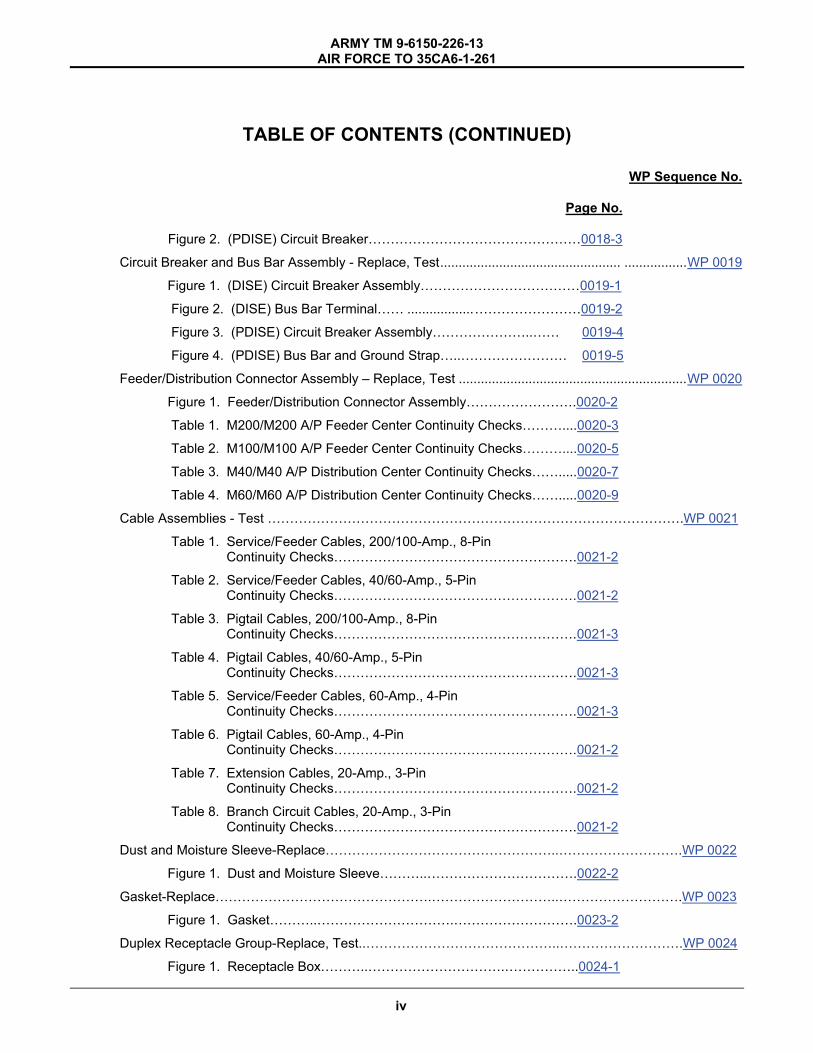
Figure 2. (PDISE) Circuit Breaker…………………………………………0018-3
Circuit Breaker and Bus Bar Assembly - Replace, Test................................................. .................WP 0019
Figure 1. (DISE) Circuit Breaker Assembly………………………………0019-1
Figure 2. (DISE) Bus Bar Terminal…… ..................……………………0019-2
Figure 3. (PDISE) Circuit Breaker Assembly…………………..…… 0019-4
Figure 4. (PDISE) Bus Bar and Ground Strap…..…………………… 0019-5
Feeder/Distribution Connector Assembly – Replace, Test ..............................................................WP 0020
Figure 1. Feeder/Distribution Connector Assembly…………………….0020-2
Table 1. M200/M200 A/P Feeder Center Continuity Checks………....0020-3
Table 2. M100/M100 A/P Feeder Center Continuity Checks………....0020-5
Table 3. M40/M40 A/P Distribution Center Continuity Checks…….....0020-7
Table 4. M60/M60 A/P Distribution Center Continuity Checks…….....0020-9
Cable Assemblies - Test ………………………………………………………………………………….WP 0021
Table 1. Service/Feeder Cables, 200/100-Amp., 8-Pin Continuity Checks……………………………………………….0021-2
Table 2. Service/Feeder Cables, 40/60-Amp., 5-Pin Continuity Checks……………………………………………….0021-2
Table 3. Pigtail Cables, 200/100-Amp., 8-Pin Continuity Checks……………………………………………….0021-3
Table 4. Pigtail Cables, 40/60-Amp., 5-Pin Continuity Checks……………………………………………….0021-3
Table 5. Service/Feeder Cables, 60-Amp., 4-Pin Continuity Checks……………………………………………….0021-3
Table 6. Pigtail Cables, 60-Amp., 4-Pin Continuity Checks……………………………………………….0021-2
Table 7. Extension Cables, 20-Amp., 3-Pin Continuity Checks……………………………………………….0021-2
Table 8. Branch Circuit Cables, 20-Amp., 3-Pin Continuity Checks……………………………………………….0021-2
Dust and Moisture Sleeve-Replace……………………………………………..……………………….WP 0022
Figure 1. Dust and Moisture Sleeve………..…………………………….0022-2
Gasket-Replace………………………………………….………………………..……………………….WP 0023
Figure 1. Gasket………..………………………….……………………….0023-2
Duplex Receptacle Group-Replace, Test..……………………………………..……………………….WP 0024
Figure 1. Receptacle Box………..………………………….……………..0024-1
iv

ARMY TM 9-6150-226-13 AIR FORCE TO 35CA6-1-261
TABLE OF CONTENTS (CONTINUED)
WP Sequence No.
Page No.
Table 1. Duplex Receptacle Box Continuity Checks…….……………..0024-2
Figure 2. Duplex Receptacle Box Wiring Diagram……………………...0024-3
Utility Light Assembly, Incandescent – Replace, Test…………………………………………… .WP 0025
Figure 1. Incandescent Light Assembly………………………………….0025-1
Table 1. Incandescent Utility Light Continuity Check…………………0025-3
Figure 2. Incandescent Utility Light Assembly Wiring Diagram…….. 0025-4
Utility Light Assembly, Fluorescent 36” - Replace………………………………………………….WP 0026
Figure 1. Fluorescent Utility Light Assembly…..………………………..0026-1
Universal Adapter – Mounting Board and Input Connector – Replace, Test…………………….WP 0027
Figure 1. Input Connector and Mounting Board………………………..0027-2
Table 1. Universal Adapter Continuity Checks………………………...0027-3
Figure 2. Universal Adapter Wiring Diagram…………………………...0027-4
Universal Adapter – Load Terminal – Replace……………………………………………………….WP 0028
Figure 1. Load Terminal……………………………………………..…... 0028-2
Cable-Type Connector - Repair………………………………………………………………………..WP 0029
Figure 1. Cable Disassembly……………………………………………..0029-1
Figure 2. Cable-Type Connector Assembly Layout……………………0029-3
Figure 3. Pneumatic Crimper……………………………………………..0029-5
Figure 4. Crimping Die…………………………………………………….0029-6
Figure 5. Connector Face/Key Positioning, 200/100-Amp, 8-Wire…………………………………………..0029-7
Figure 6. Connector Face/Key Positioning, 40/60-Amp, 5-Wire…………………………………………….. 0029-8
Figure 7. Connector Face/Key Positioning, 60-Amp, 4-Wire….…………………………………………….. 0029-8
Figure 8. Connector Face/Key Positioning, 20-Amp, 3-Wire……………………………………………..…..0029-9
Figure 9. Installing Pin with Insertion Tool………………………………0029-10
Feeder/Distribution (Wall-Type) Connector – Repair…………………………………………………WP 0030
Figure 1. Connector Layout……………………………………………….0030-1
General Wiring Maintenance/Wiring Diagrams………………………………………………..………WP 0031
Table 1. Wall/Cable Connector Tool Selection…………………………0031-3
Table 2. Crimp Tools………………………………………………………0031-4
v
ARMY TM 9-6150-226-13AIR FORCE TO 35CA6-1-261
TABLE OF CONTENTS (CONTINUED)
WP Sequence No.
Page No.
Table 3. DISE Feeder/Distribution Center Connector Repair/Fabrication Reference………………………………….0031-6
Table 4. PDISE Feeder/Distribution Center Connector
Repair/Fabrication Reference………………………………….0031-7
Figure 1. M200 (DISE) Feeder Center Wiring Diagram………………..0031-9
Figure 2. M100 (DISE) Feeder Center Wiring Diagram………………..0031-11
Figure 3. M40 (DISE) Distribution Center Wiring Diagram………….. 0031-12
Figure 4. M60 (DISE) Distribution Center Wiring Diagram………….. 0031-13
Latch/Data Plate (Enclosure Assembly) – Replace, Repair………………………………………….. WP 0032
Chapter 7– Supporting Information
References .......................................................................................................................................WP 0033
Introduction for Standard Maintenance Allocation Chart (MAC) ......................................................WP 0034
Maintenance Allocation Chart (MAC) ...............................................................................................WP 0035
Table 1. MAC for 60K IECU………………………………………………..0035-1
Table 2. Tools and Test Equipment Requirements...............................0035-5
Table 3. Remarks……………………………………………………………0035-6
Component of End Items (COEI) and Basic Issue Items (BII List)…………………………………. ..WP 0036
Figure 1. M200/M200 A/P (COEI)………………………………………….0036-2
Table 1. M200/M200 A/P (COEI) List………………………...………..0036-2
Figure 2. M100/M100 A/P (COEI)………………………………………….0036-3
Table 2. M100/M100A/P (COEI) List…………………………………..0036-3
Figure 3. M40/M40 A/P (COEI)……….…………………..………………. 0036-4
Table 3. M40/M40 A/P (COEI) List………………………...……………0036-4
Figure 4. M60/M60 A/P (COEI)……………………………………………..0036-6
Table 4. M60/M60 A/P (COEI) List…………………….………………..0036-6
Figure 5. M46 and Auxiliary (COEI)………….…………………………......0036-8
Table 5. M46 and Auxiliary (COEI) List…………………………...……..0036-8
Figure 6. Universal Adapter ……………………..………………………....0036-10
Table 6. Universal Adapter……………………………………………….0036-10
Additional Authorization List (AAL) Items………………………………………………….…………....WP 0037
Expendable/Durable Supplies and Materials List……………………………………………………....WP 0038
Table 1. Expendable/Durable Supplies and Materials List……………..0038-2
vi
ARMY TM 9-6150-226-13AIR FORCE TO 35CA6-1-261
TABLE OF CONTENTS (CONTINUED)
WP Sequence No.
Page No.
Illustrated List of Manufactured Items…………………………………………………………………....WP 0039
Table 1. Manufactured Items Part Number Index…………………….….0039-1
Table 2. Service/Feeder Cable, 40/60-Amp, 25 ft…………………….… 0039-5
Figure F-1. Service/Feeder Cable, 40/60-Amp, 25 ft…………………….… 0039-6
Table 3. Service/Feeder Cable, 40/60-Amp, 100 ft……………………... 0039-8
Figure F-2. Service/Feeder Cable, 40/60-Amp, 100 ft……………………... 0039-9
Table 4. Service/Feeder Cable, 60-Amp, 50 ft……………….……….… 0039-11
Figure F-3. Service/Feeder Cable, 60-Amp, 50 ft…………………….……0039-12
Table 5. Extension Cable, 20-Amp, 3.5 ft………………………………. 0039-14
Figure F-4. Extension Cable, 20-Amp, 3.5 ft………………………………. 0039-15
Table 6. Input Connector Assembly, 200-Amp (J1) (DISE).. …………..0039-17
Figure F-5. Input Connector Assembly, 200-Amp (J1) (DISE)… …….… 0039-18
Table 7. Input Connector Assembly, 100-Amp (J1) (DISE)………….…0039-18
Figure F-6. Input Connector Assembly, 100-Amp (J1) (DISE)…………….0039-18
Table 8. Feeder Center Output Connector Assembly, 100-Amp M200 (J4, J5, J11), M100 (J2) (DISE)..………………………...0039-21
Figure F-7. Feeder Center Output Connector Assembly, 100-Amp M200 (J4, J5, J11), M100 (J2) (DISE)..………………….……..0039-22
Table 9. Distribution Center Input Connector Assembly, 40-Amp M40 (J1) (DISE)..…………………………………………………..0039-23
Figure F-8. Distribution Center Input Connector Assembly, 40-Amp M40 (J1) (DISE)..…………………………………………….……0039-24
Table 10. Feeder Center Output Connector Assembly, 40/60-Amp M200 (J7, J8, J9, J10) (DISE)………………………….
Feeder Center Output Connector Assembly, 40/60-Amp M100 (J3, J4, J5, J6) (DISE)…..……………………….
Distribution Center Output Connector Assembly 40/60-Amp, M40 (J2) (DISE)..…………………………………..0039-25
Figure F-9. Feeder Center Output Connector Assembly, 40/60-Amp M200 (J7, J8, J9, J10) (DISE)………………………….
Feeder Center Output Connector Assembly, 40/60-Amp M100 (J3, J4, J5, J6) (DISE)..………………………….
Distribution Center Output Connector Assembly 40/60-Amp, M40 (J2) (DISE)..…………………………………..0039-26
Table 11. Distribution Center Input Connector Assembly, 60-Amp
vii
ARMY TM 9-6150-226-13AIR FORCE TO 35CA6-1-261
TABLE OF CONTENTS (CONTINUED)
WP Sequence No.
Page No.
M60 (J1) (DISE)..……………………………………………….0039-27
Figure F-10. Distribution Center Input Connector Assembly, 60-Amp M60 (J1) (DISE)..………………………………………………0039-28
Table 12. Distribution Center Output Connector Assembly, 60-Amp M60 (J2) (DISE)..………………………………………………0039-29
Figure F-11. Distribution Center Output Connector Assembly, 60-Amp M60 (J2) (DISE)…….…………………………………………0039-30
Table 13. Distribution Center Output Connector Assembly, 20-Amp M40 (J3 thru J14), M60 (J3 thru J8) (DISE)….…………….0039-31
Figure F-12. Distribution Center Output Connector Assembly, 20-Amp M40 (J3 thru J14), M60 (J3 thru J8) (DISE)…………….….0039-32
Table 14. Feeder Center Output Connector Assembly, 60-Amp M200 (J6), M100 (J8) (DISE)..…….....……………………...0039-33
Figure F-13. Feeder Center Output Connector Assembly, 60-Amp M200 (J6), M100 (J8) (DISE)...…..……………………….….0039-34
Table 15. Feeder Center Output Connector Assembly, 20-Amp M100 (J7) (DISE).…………….………………………………. 0039-35
Figure F-14. Feeder Center Output Connector Assembly, 20-Amp M100 (J7) (DISE)…………………………………………….…0039-36
Table 16. Pigtail Cable, 200-Amp, 4 ft.………………………………….0039-37
Figure F-15. Pigtail Cable, 200-Amp, 4 ft…………………………….……..0039-38
Table 17. Pigtail Cable, 100-Amp, 4 ft.………………………….……….0039-40
Figure F-16. Pigtail Cable, 100-Amp, 4 ft.…………………………………..0039-41
Table 18. Pigtail Cable, 40/60-Amp, 4ft..………………………………..0039-43
Figure F-17. Pigtail Cable, 40/60-Amp, 4ft..………………………………..0039-44
Table 19. Pigtail Cable, 60-Amp, 4ft..…………………………………...0039-46
Figure F-18. Pigtail Cable, 60-Amp, 4 ft….………………………....….…..0039-47
Table 20. Service/Feeder Cable, 200-Amp, 25 ft…………………….…0039-49
Figure F-19. Service/Feeder Cable, 200-Amp, 25 ft…………………….. .0039-50
Table 21. Service/Feeder Cable, 100-Amp, 50 ft……………………… 0039-52
Figure F-20. Service/Feeder Cable, 100-Amp, 50 ft……………………… 0039-53
Table 22. Service/Feeder Cable, 40/60-Amp, 50 ft……………………. 0039-55
Figure F-21. Service/Feeder Cable, 40/60-Amp, 50 ft…………………… 0039-56
Table 23. Service/Feeder Cable, 60-Amp, 100 ft……………………… 0039-58
Figure F-22. Service/Feeder Cable, 60-Amp, 100 ft……………………… 0039-59
viii

ARMY TM 9-6150-226-13AIR FORCE TO 35CA6-1-261
TABLE OF CONTENTS (CONTINUED)
WP Sequence No.
Page No.
Table 24. Extension Cable, 20-Amp, 15 ft………………………………0039-61
Figure F-23. Extension Cable, 20-Amp, 15 ft………………………..…..…0039-62
Table 25. Extension Cable, 20-Amp, 25 ft………………………………0039-64
Figure F-24. Extension Cable, 20-Amp, 25 ft………………………..…..…0039-65
Table 26. Extension Cable, 20-Amp, 50 ft………………………………0039-67
Figure F-25. Extension Cable, 20-Amp, 50 ft………………………..…..…0039-68
Table 27. Input Connector Assembly, 200-Amp (J1) (PDISE).. ……...0039-70
Figure F-26. Input Connector Assembly, 200-Amp (J1) (PDISE)…..……0039-71
Table 28. Input Connector Assembly, 100-Amp (J1) (PDISE)……….0039-72
Figure F-27. Input Connector Assembly, 100-Amp (J1) (PDISE)…… ….0039-73
Table 29. Feeder Center Output Connector Assembly, 100-Amp M200 A/P (J4) (PDISE) .......................................................0039-74
Table 30. Feeder Center Output Connector Assembly, 100-Amp M200 A/P (J5) (PDISE)….……….………….…………………0039-74
Table 31. Feeder Center Output Connector Assembly, 100-Amp M200 A/P (J11) (PDISE)…..………………….………………..0039-75
Table 32. Feeder Center Output Connector Assembly, 100-Amp M100 A/P (J2) (PDISE)…...………………….…………………0039-75
Figure F-28. Feeder Center Output Connector Assembly, 100-Amp M200 A/P (J4, J5, J11), M100 A/P (J2) (PDISE)..……..…….0039-76
Table 33. Distribution Center Input Connector Assembly, 40-Amp M40 A/P (J1) (PDISE).………………..…………………………0039-77
Figure F-29. Distribution Center Input Connector Assembly, 40-Amp M40 A/P (J1) (PDISE)……………………………………………0039-78
Table 34. Feeder Center Output Connector Assembly, 40/60-Amp M200 A/P (J7 and J9) (PDISE)…………..…………….……….0039-79
Table 35. Feeder Center Output Connector Assembly, 40/60-Amp M200 A/P (J8 and J10) (PDISE)…..….………………………..0039-79
Table 36. Feeder Center Output Connector Assembly, 40/60-Amp M100 A/P (J3 and J5) (PDISE)…..…….……………………....0039-80
Table 37. Feeder Center Output Connector Assembly, 40/60-Amp M100 A/P (J4 and J6) (PDISE)…..……….…………..………..0039-80
Table 38. Distribution Center Output Connector Assembly 40/60-Amp, M40 A/P (J2) (PDISE)..……….…………………..0039-80
Figure F-30. Feeder Center Output Connector Assembly, 40/60-Amp M200 A/P (J7, J8, J9, J10) (PDISE)………………………….
Feeder Center Output Connector Assembly, 40/60-Amp
ix
ARMY TM 9-6150-226-13AIR FORCE TO 35CA6-1-261
TABLE OF CONTENTS (CONTINUED)
WP Sequence No.
Page No.
...................... M100 A/P (J3, J4, J5, J6) (PDISE)..………………………….
Distribution Center Output Connector Assembly 40/60-Amp, M40 A/P (J2) (PDISE)..………………….………..0039-81
Table 39. Distribution Center Input Connector Assembly, 60-Amp M60 A/P (J1) (PDISE).…………………………..……………….0039-82
Figure F-31. Distribution Center Input Connector Assembly, 60-Amp M60 A/P (J1) (PDISE).……………..……………………………0039-83
Table 40. Distribution Center Output Connector Assembly, 60-Amp M60 A/P (J2) (PDISE).………..…………………………………0039-84
Figure F-32. Distribution Center Output Connector Assembly, 60-Amp M60 A/P (J2) (PDISE)……….…….……………………………0039-85
Table 41. Distribution Center Output Connector Assembly, 20-Amp M40 A/P (J3, J5, J7, J9, J11, J13) (PDISE)….……………....0039-86
Table 42. Distribution Center Output Connector Assembly, 20-Amp M40 A/P (J4, J6, J8, J10, J12, J14) (PDISE)….……….........0039-86
Table 43. Distribution Center Output Connector Assembly, 20-Amp M60 A/P (J3, J5, J7,) (PDISE)…………....…………………...0039-87
Table 44. Distribution Center Output Connector Assembly, 20-Amp M60 A/P (J4, J6, J8,) (PDISE)…………....…………………...0039-87
Figure F-33. Distribution Center Output Connector Assembly, 20-Amp M40 A/P (J3 thru J14), M60 (J3 thru J8) (PDISE)…………..0039-88
Table 45. Feeder Center Output Connector Assembly, 20-Amp M200 A/P (J6) (PDISE)……………………………………...…0039-89
Table 46. Feeder Center Output Connector Assembly, 20-Amp M100 A/P (J8) (PDISE)…………………………………………0039-89
Figure F-34. Feeder Center Output Connector Assembly, 20-Amp M200 A/P (J6) and M100 A/P (J8) (PDISE)………………….0039-90
Table 47. Feeder Center Output Connector Assembly, 20-Amp M100 A/P (J7) (PDISE)…………………………………………0039-91
Figure F-35. Feeder Center Output Connector Assembly, 20-Amp M100 A/P (J7) (PDISE)…………………………………………0039-92
Torque Limits -............................................................................................................................ WP 0040
Table 1. Torque Limits for Circuit Breaker Lugs (DISE)...................0040-1
Table 2. Torque Limits for Circuit Breaker Lugs (PDISE).................0040-2
Table 3. Torque Limits for Self-Locking Nuts………………………...0040-2
Chapter 8– Rear Matter………………….……………….………………………………….………………………...
x
ARMY TM 9-6150-226-13AIR FORCE TO 35CA6-1-261
HOW TO USE THIS MANUAL
This manual is divided into Work Packages (WP). Each WP is an independent, task-oriented unit. Only essential information is provided. WPs cover the subjects of theory of operation, operating instructions, troubleshooting, preventative maintenance checks, maintenance instructions, and fabrication of certain components. The Table of Contents provides a complete list of chapters and WPs pertinent to the maintaining of all DISE/PDISE systems. The WPs are arranged in numerical sequence based on the maintenance level or task associated for breakdown. There may be two separate procedures associated for the DISE model systems and the PDISE model systems. Commonalities and differences in the models are described in WP 0001. Each maintenance WP lists the tasks covered, initial set-up requirements, tools required, equipment conditions, reference materials and material/parts required. Maintenance procedures are sometimes integrated with illustrations. To locate information, refer to the Table of Contents in the front of the TM. References to tables or figures within a WP are made by numbers, e.g. Table 2, or Figure 3. A reference to another WP merely includes the WP number, e.g. WP 0003. To find a particular procedure or topic, it is necessary to refer to that WP. In most cases, redundant procedures may resort to the applicable WP that that particular component be referenced. To find a particular part for replacement, it will be necessary to use the Repair Parts and Special Tools List (RPSTL), TM 9-6150-226-13P (also known as the Illustrated Parts Breakdown). Detailed instructions for use of the RPSTL are found in TM 9-6150-226-13P. GENERAL
In order to use this manual efficiently, there are several things you need to know. All references in this manual are to work packages or to another manual. Throughout this manual, text is keyed to illustrations by numbered callouts. When an item is called out in a procedure, a number in parentheses in the text corresponds with a number on the illustration.
INDEXES
This manual is organized to help you quickly find the information needed. There are useful indexes or lists:
Table of Contents. The Table of Contents lists, in the order of presentation, all chapters, and Work Packages contained in this manual.
Troubleshooting Symptom Index. The Troubleshooting Symptom Index lists parts of the system and possible malfunctions with references to the corrective action.
Component of End Item (COEI). A list of items that are part of the end item, but are shipped separately. It is not an authorization to requisition replacements.
Basic Issue Items (BII). A list of minimum essential items required when system
xi/xii Blank


Chapter 1
General Information Equipment Description
and Theory of Operation


TM 9-6150-226-13 0001
OPERATOR, FIELD AND SUSTAINMENT MAINTENANCE
DISE AND PDISE SYSTEMS GENERAL INFORMATION
SCOPE This manual contains an equipment description, operating instructions and maintenance procedures for the electrical distribution and illumination systems (Distribution Illumination Systems, Electrical-DISE) and (Power Distribution Illumination Systems, Electrical-PDISE). It also includes references to other publications and maintenance information in support of this equipment as well as warranty specific instructions. This manual covers the following models: DISE PDISE
(1) M200 Electrical Feeder System; M200 A/P Electrical Feeder System
(2) M100 Electrical Feeder System; M100 A/P Electrical Feeder System
(3) M40 Electrical Distribution System; M40 A/P Electrical Distribution System
(4) M60 Electrical Distribution System ; M60 A/P Electrical Distribution
(5) M46 Electrical Utility Assembly; M46 Electrical Utility Assembly(6) Auxiliary Equipment
The main purpose of this equipment is to distribute electrical power from the power source (supplied separately) to user equipment during field conditions and to provide illumination for field shelters. MAINTENANCE FORMS AND RECORDS. Department of the Army forms and procedures used for equipment maintenance will be those prescribed by DA Pam 750-8, The Army Maintenance Management System (TAMMS) update. REPORTING EQUIPMENT IMPROVEMENT RECOMMENDATION (EIR). If your equipment needs improvement, let us know. Send us an EIR. You, the user, are the only one who can tell us what you don’t like about your equipment. Let us know why you don’t like the design or performance. Put it on an SF 368 (Product Quality Deficiency Report). Mail it to us at: Commander, US Army Communications-Electronics and Life Cycle Material Command, Fort Monmouth, New Jersey 07703-5006, ATTN: AMSEL-LC-LEO-D-CS-CFO. We will send you a reply. CORROSION PREVENTION AND CONTROL Corrosion Prevention and Control (CPC) of Army material is a continuing concern. It is important that any Corrosion problems with this item be reported so that the problem can be corrected and improvements can be made to prevent the problem in future items. While corrosion is typically associated with rusting of Metals, it can also include deterioration of other materials, such as rubber and plastic. Unusual cracking, softening, swelling, or breaking of these materials may be a corrosion problem. If a corrosion problem is identified, it can be reported using SF 368. Use of key words such as “corrosion”,”rust”, “deterioration”, or “cracking” will ensure that the information is identified as a CPC problem. The form should be submitted to the address specified in DA PAM 750-8, Functional Users Manual for the Army Maintenance Management System (TAMMS).
0001-1 Change 1

TM 9-6150-226-13 0001
Change 1 0001-2
DESTRUCTlON OF ARMY MATERIEL TO PREVENT ENEMY USE. For general destruction procedures for this equipment, refer to TM 750-244-3, Procedures for Destruction of Equipment to Prevent Enemy Use (Mobility Equipment Command). PREPARATION FOR STORAGE AND SHIPMENT Before placing the DISE/PDISE system in storage or preparing for shipment, all maintenance checks and services must be applied; defects and failures corrected; and Maintenance Work Orders (MWO’s) applied. See WP 0011 for applicable Service Level PMCS and WP 0014 for proper storage information. Ensure any warranty claim/paperwork is attached to the unit being shipped. WARRANTY INFORMATION PDISE equipment is warranted for a period of one year beginning on the date of acceptance by the Government Inspector, as defined by the “DATE INSP” found on the data plate and/or DD 250. This warranty covers all components found in WP 0036 (Components of End Item) and furnishing of new items to replace any that prove to be nonconforming and/or defective within the given time period. Any means of reimbursement will be determined by the warranty claim office found below. Warranty Limitations:
CAUTION
Failure to recognize these limitations could potentially void the warranty and hold the unit fully accountable for reimbursement loss.
(1) This warranty does not apply to any components that have been subject to abuse, misuse, neglect, or accident, and/or have been repaired, maintained, or altered in any way that has adversely affected their condition.
(2) Warranty only applies to components which have been inspected, maintained, and operated IAW standard military service maintenance procedures as per this TM.
(3) Combat damage is not covered per this warranty to the extent that the defect/s in question
are proximately caused by such combat damage.
(4) If the suspect component/s is found to be “False Pulls” or “No Evidence of Failure” after Government review, the unit will be held accountable for any costs incurred.
(5) Only components identified with CAGE code (OCJZ9) and/or covered under contract
number W15P7T-08-D-A007 are considered valid under this warranty. (6) Warranty does not cover damage caused by acts of God or the public enemy to include
fires, floods, unusually severe weather, and/or acts of the Government in its sovereign or contractual capacity.
Warranty Claim Procedures:
(1) DA Form 2407 (Maintenance Request) is the required form for filling out warranty claim actions. Ensure all pertinent data is filled out according to DA PAM 750-8 and in accordance with all limitations above.
TM 9-6150-226-13 0001
0001-3 Change 1
(2) Failed component/s should also be accompanied with an “Exchange Tag”, DA Form 2402. (3) Contact CECOM PDISE warranty claims office for disposition of failed equipment:
COMMANDER, U.S. Army Communications Electronics Life Cycle Maintenance Command (C-E LCMC) and Fort Monmouth, ATTN: AMSEL-LC-CCS-E-EC Fort Monmouth, NJ 07703 Commercial: 732-532-8238 / 732-427-4767 DSN: 992-8238 / 987-4767
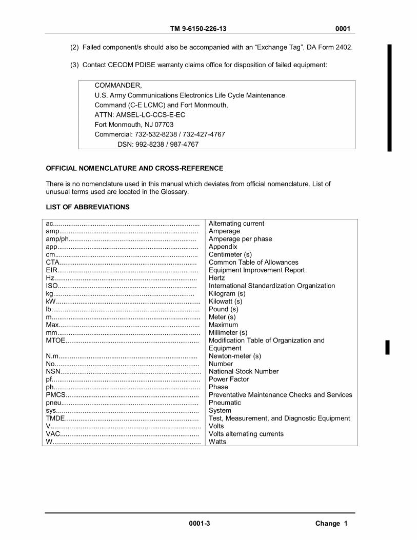
OFFICIAL NOMENCLATURE AND CROSS-REFERENCE There is no nomenclature used in this manual which deviates from official nomenclature. List of unusual terms used are located in the Glossary. LlST OF ABBREVIATIONS ac.............................................................................. amp.......................................................................... amp/ph.................................................................... app........................................................................... cm............................................................................ CTA......................................................................... EIR........................................................................... Hz............................................................................ ISO.......................................................................... kg........................................................................... kW............................................................................. lb............................................................................... m............................................................................... Max........................................................................... mm............................................................................ MTOE....................................................................... N.m.......................................................................... No............................................................................. NSN........................................................................... pf............................................................................... ph.............................................................................. PMCS....................................................................... pneu......................................................................... sys............................................................................ TMDE....................................................................... V................................................................................ VAC.......................................................................... W...............................................................................
Alternating current Amperage Amperage per phase Appendix Centimeter (s) Common Table of Allowances Equipment Improvement Report Hertz International Standardization Organization Kilogram (s) Kilowatt (s) Pound (s) Meter (s) Maximum Millimeter (s) Modification Table of Organization and Equipment Newton-meter (s) Number National Stock Number Power Factor Phase Preventative Maintenance Checks and Services Pneumatic System Test, Measurement, and Diagnostic Equipment Volts Volts alternating currents Watts
TM 9-6150-226-13 0001
Change 1 0001-4
QUALITY ASSURANCE/QUALITY CONTROL The following manuals are required for quality assurance/quality control of DISE and PDISE equipment: TM 9-237;TM 38-230-1;TM 38-230-2, TM 43-0139; and FM 10-16. SAFETY, CARE AND HANDLING. Be alert and adhere to WARNINGS, CAUTIONS, and NOTES. These provide for safe operation of the equipment, and protect you and your equipment from injury and damage. CALIBRATION DISE/PDISE equipment does not require calibration. SUPPORTING INFORMATION FOR REPAIR PARTS AND SPECIAL TOOLS EQUIPMENT Refer to the Maintenance Allocation Chart (MAC) in WP 0034 for a listing of maintenance items and tools or test equipment. Refer to TM 9-6150-226-13P (Repair Parts and Special Tools List Maintenance Manual) for any parts and materials information. EQUIPMENT CHARACTERISTICS, CAPABILITIES, AND FEATURES.
DISE/PDISE is a family of power distribution and illumination equipment which transmits
electrical power between power generation and power using equipment. Some DISE/PDISE supplements current field illumination and adds distribution capabilities.
DISE/PDISE consists of items illustrated and listed in Figures 2 through 7. It is
used to form a consolidated power network by adding components to meet specific organizational missions and requirements.
DISE/PDISE permits using fields more flexibility by consolidating power sources.
DISE/PDISE provides flexibility to field operations and can
be quickly assembled/disassembled for rapid relocation.
DISE/PDISE equipment is designed for basic climatic (120 to -25° F [49 to -32° C) and field conditions.
DISE/PDISE equipment is designed to be used with generator sets (120/208 VAC,
50/60 Hz, 5 to 200 kW).
DISE/PDISE system and user’s electrical equipment are protected by circuit breakers within the DISE/PDISE equipment.
DISE/PDISE equipment uses military standard connectors.
DISE/PDISE equipment is compatible with International Standardization Organization (IS0)
containers and Tent Extendable, Modular, Personnel (TEMPER).
Line distance from generator to load is limited to a total of 300 feet (91.4m) at maximum load, because line distance greater than 300 feet (91.4m) would cause an unacceptable voltage loss. Refer to Table 3 to determine voltage loss at rated current.
The M46 electrical utility assembly can be used to illuminate field shelters. The M46 is not
intended to replace existing lighting sets, but is intended to augment and expand current capabilities.

TM 9-6150-226-13 0001
0001-5 Change 1
LOCATION AND DESCRIPTION OF MAJOR COMPONENTS.
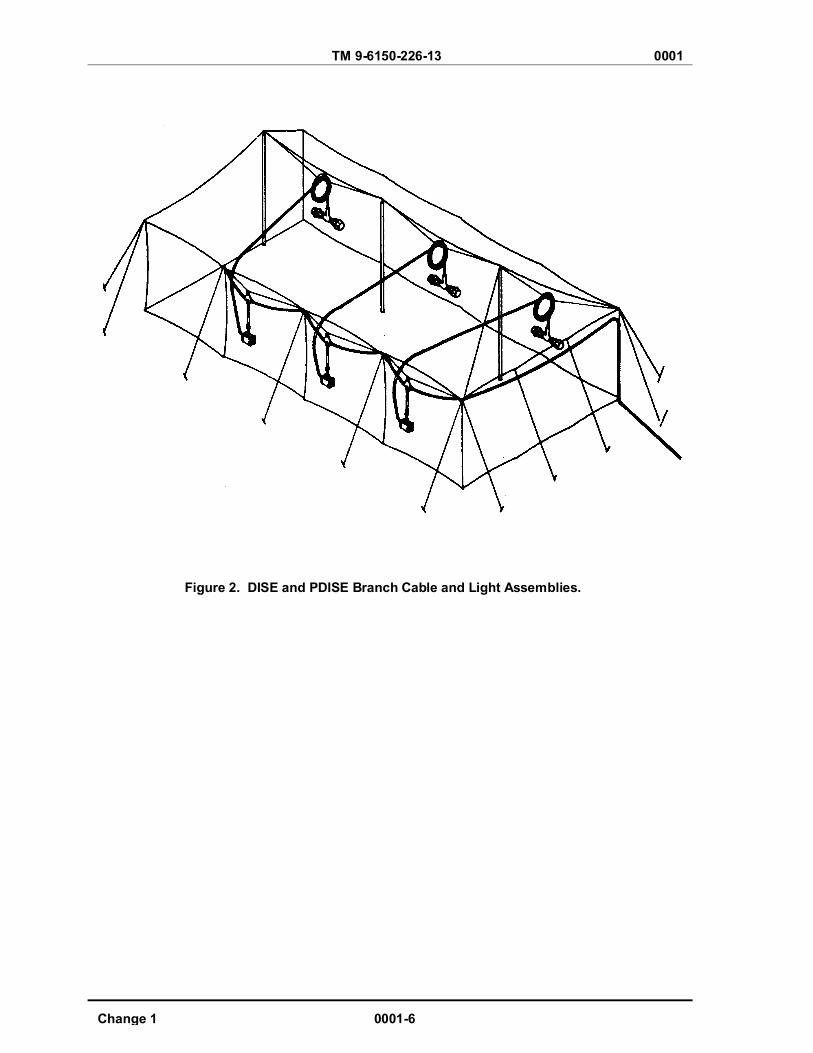
Typical System Placement. The quantity, location, and placement of DISE and PDISE equipment is dependent upon field conditions and user needs. Figure 1 is a typical field placement of a 3-phase power distribution system. Figure 2 shows details of DISE and PDISE equipment inside the user’s tent.
System Components. The components of the five basic systems for DISE and PDISE are illustrated in Figures 2 thru 7.
Figure 1. Typical Field Placement
TM 9-6150-226-13 0001
Change 1 0001-6
Figure 2. DISE and PDISE Branch Cable and Light Assemblies.

TM 9-6150-226-13 0001
0001-7 Change 1
M200/M200 A/P- (3 Phase) Electrical Feeder System Component Listing (See Figure 3) (1) Electrical feeder center, 3-ph, 120/208 V, 200 amp/ph (2) Pigtail cable assembly, 4 ft (1.2 m), 200-amp, 8-pin (3) Service/feeder cable assembly, 25 ft (7.6m), 200-amp, 8-pin (4 ea.) (4) Cable carrying strap (16 ea)
Figure 3. Electrical Feeder System, M200 and M200 A/P, (3-Phase).
TM 9-6150-226-13 0001
Change 1 0001-8
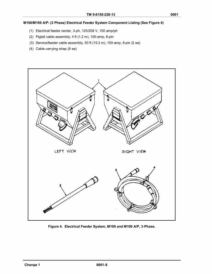
M100/M100 A/P- (3 Phase) Electrical Feeder System Component Listing (See Figure 4) (1) Electrical feeder center, 3-ph, 120/208 V, 100 amp/ph
(2) Pigtail cable assembly, 4 ft (1.2 m), 100-amp, 8-pin
(3) Service/feeder cable assembly, 50 ft (15.2 m), 100-amp, 8-pin (2 ea)
(4) Cable carrying strap (8 ea)
Figure 4. Electrical Feeder System, M100 and M100 A/P, 3-Phase.

TM 9-6150-226-13 0001
0001-9 Change 1
M40/ M40 A/P- (3 Phase) Electrical Distribution System Component Listing (See Figure 5)
(1) Distribution center, 3-ph, 120/208 VAC, 40 amp/ph
(2) Pigtail cable, 4 ft (1.2 m), 40 amps, 5-pin
(3) Service/feeder cable assembly, 50 ft (15.2 m), 40/60-amp, 5-pin (2 ea)
(4) Cable carrying strap (8 ea)
(5) Extension cable assembly, 50 ft (15.2 m), 20-amp, 3-pin (3 ea)
(6) Extension cable assembly, 25 ft (7.6 m), 20-amp, 3-pin (3 ea)
(7) Receptacle group 2-duplex box enclosure, 120 VAC, 20 amp
(8) Packing List
(9) Transit and storage container
(10) Interface cable
Figure 5. Electrical Distribution System, M40 and M40 A/P, 3-Phase.

TM 9-6150-226-13 0001
Change 1 0001-10
M60/M60 A/P- (Single Phase) Electrical Distribution System Component Listing (See Figure 6)
(1) Distribution center, single-phase, 120 V, 60 amp
(2) Pigtail cable assembly, 4 fit (1.2 m), 60-amp, 4-pin
(3) Service/feeder cable assembly, 100 ft (30.5 m), 60-amp, 4-pin
(4) Cable carrying strap (16 ea)
(5) Extension cable assembly, 50 ft (15.2 m), 20-amp, 3-pin (3 ea)
(6) Extension cable assembly, 25 ft (7.6 m), 20-amp, 3-pin (3 ea)
(7) Receptacle group 2-duplex box enclosure, 120 V, 20 amp
(8) Packing List
(9) Transit and storage-container
(10) Interface cable
Figure 6. Electrical Distribution System, M60 and M60 A/P Single-Phase.
TM 9-6150-226-13 0001
0001-11 Change 1
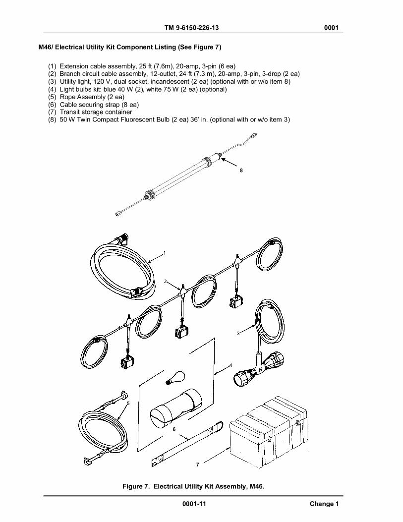
M46/ Electrical Utility Kit Component Listing (See Figure 7)
(1) Extension cable assembly, 25 ft (7.6m), 20-amp, 3-pin (6 ea) (2) Branch circuit cable assembly, 12-outlet, 24 ft (7.3 m), 20-amp, 3-pin, 3-drop (2 ea) (3) Utility light, 120 V, dual socket, incandescent (2 ea) (optional with or w/o item 8) (4) Light bulbs kit: blue 40 W (2), white 75 W (2 ea) (optional) (5) Rope Assembly (2 ea) (6) Cable securing strap (8 ea) (7) Transit storage container (8) 50 W Twin Compact Fluorescent Bulb (2 ea) 36’ in. (optional with or w/o item 3)
8
Figure 7. Electrical Utility Kit Assembly, M46.
7
6
TM 9-6150-226-13 0001
Change 1 0001-12
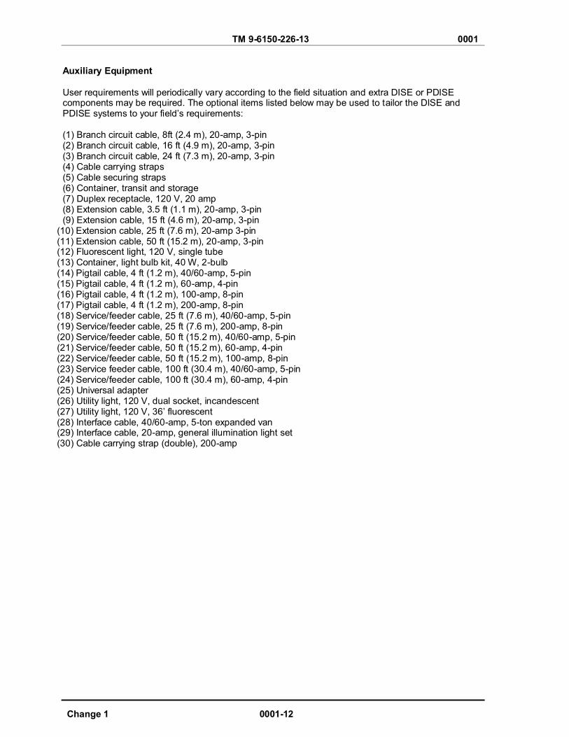
Auxiliary Equipment User requirements will periodically vary according to the field situation and extra DISE or PDISE components may be required. The optional items listed below may be used to tailor the DISE and PDISE systems to your field’s requirements: (1) Branch circuit cable, 8ft (2.4 m), 20-amp, 3-pin (2) Branch circuit cable, 16 ft (4.9 m), 20-amp, 3-pin (3) Branch circuit cable, 24 ft (7.3 m), 20-amp, 3-pin (4) Cable carrying straps (5) Cable securing straps (6) Container, transit and storage (7) Duplex receptacle, 120 V, 20 amp (8) Extension cable, 3.5 ft (1.1 m), 20-amp, 3-pin (9) Extension cable, 15 ft (4.6 m), 20-amp, 3-pin
(10) Extension cable, 25 ft (7.6 m), 20-amp 3-pin (11) Extension cable, 50 ft (15.2 m), 20-amp, 3-pin (12) Fluorescent light, 120 V, single tube (13) Container, light bulb kit, 40 W, 2-bulb (14) Pigtail cable, 4 ft (1.2 m), 40/60-amp, 5-pin (15) Pigtail cable, 4 ft (1.2 m), 60-amp, 4-pin (16) Pigtail cable, 4 ft (1.2 m), 100-amp, 8-pin (17) Pigtail cable, 4 ft (1.2 m), 200-amp, 8-pin (18) Service/feeder cable, 25 ft (7.6 m), 40/60-amp, 5-pin (19) Service/feeder cable, 25 ft (7.6 m), 200-amp, 8-pin (20) Service/feeder cable, 50 ft (15.2 m), 40/60-amp, 5-pin (21) Service/feeder cable, 50 ft (15.2 m), 60-amp, 4-pin (22) Service/feeder cable, 50 ft (15.2 m), 100-amp, 8-pin (23) Service feeder cable, 100 ft (30.4 m), 40/60-amp, 5-pin (24) Service/feeder cable, 100 ft (30.4 m), 60-amp, 4-pin (25) Universal adapter (26) Utility light, 120 V, dual socket, incandescent (27) Utility light, 120 V, 36’ fluorescent (28) Interface cable, 40/60-amp, 5-ton expanded van (29) Interface cable, 20-amp, general illumination light set (30) Cable carrying strap (double), 200-amp
TM 9-6150-226-13 0001
0001-13 Change 1
DIFFERENCE BETWEEN MODELS.
The major difference between the DISE and PDISE systems are:
(1) The DISE models (M40, M60, M100 and M200) use thermal-magnetic circuit breakers
while the PDISE models (M40 A/P, M60 A/P, M100 A/P and M200 A/P) use hydraulic-magnetic circuit breakers.
(2) The DISE models use one length of wire for each model inside the enclosure assembly
while the PDISE models use different lengths of wire due to bus bar location and type of circuit breaker.
(3) The DISE models have ground fault circuit interruption while the PDISE models do not use
the ground fault circuit interruption circuit breaker. (4) The inside covers for DISE models are designed differently from PDISE models due to
size of circuit breakers. Three-Phase DISE and PDISE Equipment. The M40, M40A/P, M100, M100A/P, M200, and M200 A/P systems require a 3-phase electrical power source rated at 208VAC, 50/60 Hz for input power. These systems will provide 3-phase (208 VAC, 50/60 Hz) or single-phase (120 VAC, 50/60 Hz) electrical power, depending on which output receptacles are used. These three systems will interconnect to provide a 3-phase plus single-phase electrical network of up to 72 kW total capacity.
Single-Phase DISE and PDISE Equipment. The M60 and M60 A/P systems require a single-phase electrical power source rated at 120 V ac, 50/60 Hz, for input power. This system will provide only single-phase (120 VAC, 50/60 Hz) electrical power at the output receptacles.
Electrical Utility Assembly. The M46 system connects to the M60 system outputs or to the single-phase outputs of the 3-phase systems (M40, M40 A/P, M100, M100 A/P, M200 and M200 A/P). The M46 system consists of various electrical cables, lights for illumination, and standard household type duplex receptacles for plugging in electrical loads, not to exceed the rating of the circuit breaker. The M46 may be substituted with the 36’ in. fluorescent light assembly and/or a larger container to accommodate its length.

TM 9-6150-226-13 0001
Change 1 0001-14
COMMON FEATURES BETWEEN SETS
Feeder/Distribution Centers:
(a) Each center uses a 4-foot (1.2 m) pigtail cable to connect to the generator.
(b) Each center is equipped with a master circuit breaker rated at the maximum permissible load.
(c) Each center is equipped with phase indicator lights which indicate the presence of
input power.
(d) Each center is equipped with branch circuits that are individually protected with circuit breakers.
Cables:
(a) Cables are equipped with at least one phase wire, one neutral wire, and one ground
wire.
(b) Cables are equipped with military standard connectors which mate according to amperage rating. Cables designed for different amperages will not connect.
(c) Cables are equipped with covers to protect the connectors from moisture and dirt.
WARNING High voltage is present in this system. DISE/PDISE supports equipment using 120/208 VAC. Do not rely on the color of the wire insulation for phase color-coding. The insulation on the wires inside the cable jacket may vary, depending on supplier. Wires will be color coded to designate the phases. If the wire color coding cannot be determined, notify next higher level of maintenance to perform continuity test. Perform a continuity test to verify correct phase designations in accordance with identified color.
(d) Cable wires are color-coded as follows:
1 Phase A (L1)-Black
2 Phase B (L2)-Red
3 Phase C (L3)-Blue 4 Neutral N (LO)-White 5 Ground G-Green or bare wire
Systems: All systems are designed to provide correct phase, neutral, and ground matching.
TM 9-6150-226-13 0001
0001-15 Change 1
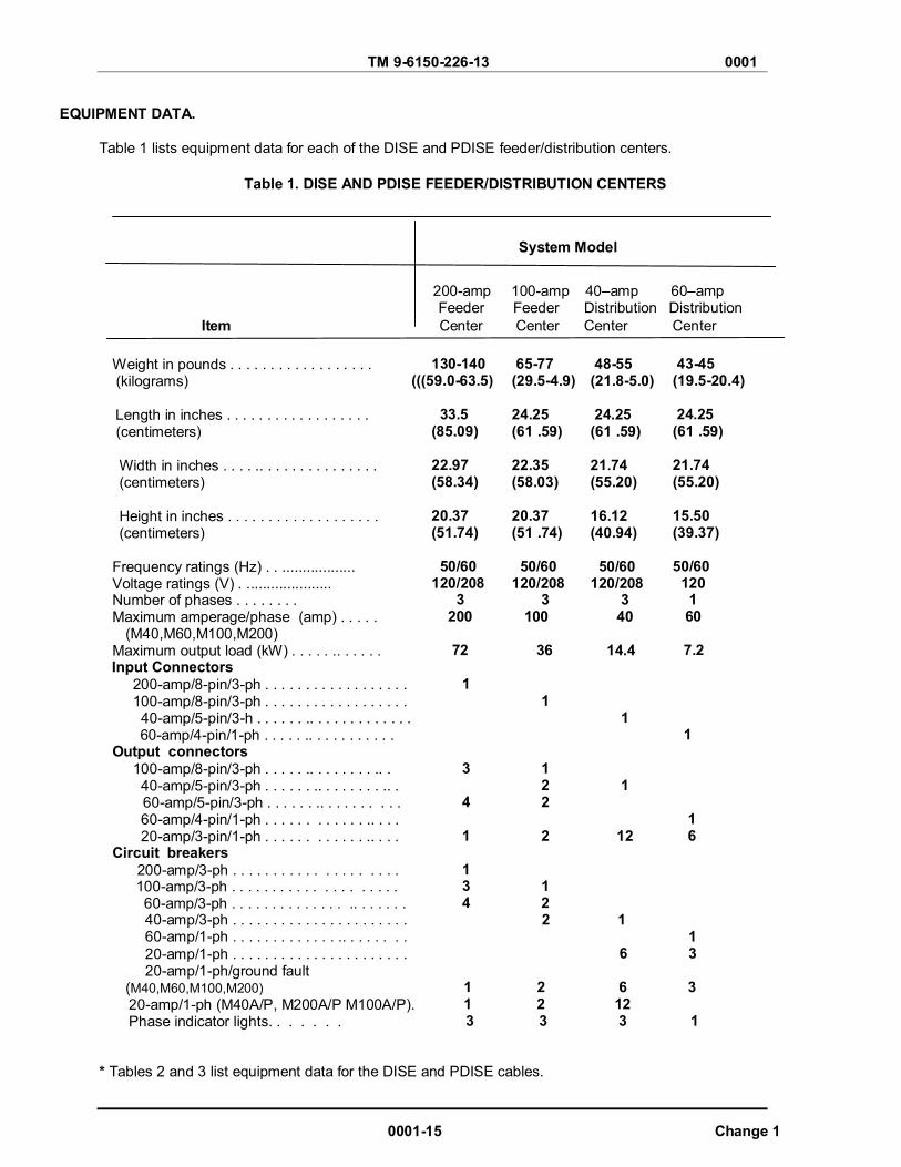
EQUIPMENT DATA.
Table 1 lists equipment data for each of the DISE and PDISE feeder/distribution centers.
Table 1. DISE AND PDISE FEEDER/DISTRIBUTION CENTERS
System Model
200-amp 100-amp 40–amp 60–amp
Feeder Feeder Distribution Distribution Item Center Center Center Center
Weight in pounds . . . . . . . . . . . . . . . . . . (kilograms) Length in inches . . . . . . . . . . . . . . . . . . (centimeters)
Width in inches . . . . .. . . . . . . . . . . . . . . (centimeters)
Height in inches . . . . . . . . . . . . . . . . . . . (centimeters)
Frequency ratings (Hz) . . .................. Voltage ratings (V) . ..................... Number of phases . . . . . . . . Maximum amperage/phase (amp) . . . . .
(M40,M60,M100,M200) Maximum output load (kW) . . . . . .. . . . . .
Input Connectors 200-amp/8-pin/3-ph . . . . . . . . . . . . . . . . . . 100-amp/8-pin/3-ph . . . . . . . . . . . . . . . . . . 40-amp/5-pin/3-h . . . . . . .. . . . . . . . . . . . .
60-amp/4-pin/1-ph . . . . . .. . . . . . . . . . . Output connectors 100-amp/8-pin/3-ph . . . . . .. . . . . . . . .. . 40-amp/5-pin/3-ph . . . . . . .. . . . . . . . .. .
60-amp/5-pin/3-ph . . . . . . .. . . . . . . . . . 60-amp/4-pin/1-ph . . . . . . . . . . . . .. . . . 20-amp/3-pin/1-ph . . . . . . . . . . . . .. . . . Circuit breakers 200-amp/3-ph . . . . . . . . . . . . . . . . . . . .
100-amp/3-ph . . . . . . . . . . . . . . . . . . . . 60-amp/3-ph . . . . . . . . . . . . . . .. . . . . . .
130-140 (((59.0-63.5)
33.5 (85.09) 22.97 (58.34) 20.37 (51.74) 50/60 120/208 3 200 72
1
3
4
1
1 3 4
65-77 (29.5-4.9) 24.25 (61 .59) 22.35 (58.03) 20.37 (51 .74) 50/60 120/208
3 100 36
1
1 2 2
2
1 2
48-55 (21.8-5.0) 24.25 (61 .59) 21.74 (55.20) 16.12 (40.94) 50/60 120/208
3 40
14.4
1
1
12
43-45 (19.5-20.4) 24.25 (61 .59) 21.74 (55.20) 15.50 (39.37) 50/60 120 1 60 7.2 1 1 6
40-amp/3-ph . . . . . . . . . . . . . . . . . . . . . . 2 1 60-amp/1-ph . . . . . . . . . . . . . .. . . . . . . . 1 20-amp/1-ph . . . . . . . . . . . . . . . . . . . . . . 20-amp/1-ph/ground fault
(M40,M60,M100,M200) 20-amp/1-ph (M40A/P, M200A/P M100A/P). Phase indicator lights. . . . . . .
* Tables 2 and 3 list equipment data for the DISE and PDISE cables.
6 3 1 2 6 3 1 2 12
3 3 3 1
TM 9-6150-226-13 0001
Change 1 0001-16
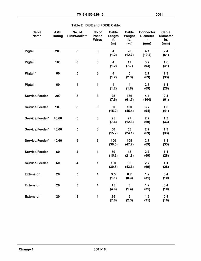
Table 2. DISE and PDISE Cable.
Cable Name
AMP Rating
No. of Pins/Sockets
No of Phase Wires
Cable Length
ft (m)
Cable Weight
lb. (kg)
Connector Diameter
in (mm)
Cable Diameter
in. (mm)
Pigtail Pigtail Pigtail* Pigtail Service/Feeder Service/Feeder Service/Feeder* Service/Feeder* Service/Feeder* Service/Feeder Service/Feeder Extension Extension Extension
200
100
60
60
200
100
40/60
40/60
40/60
60
60
20
20
20
8 8 5 4 8 8 5 5 5 4 4 3 3 3
3 3 3 1 3 3 3 3 3 1 1 1 1 1
4 (1.2)
4
(1.2)
4 (1.2)
4
(1.2)
25 (7.6)
50
(15.2)
25 (7.6)
50
(15.2)
100 (30.5)
50
(15.2)
100 (30.5)
3.5
(1.1)
15 (4.6)
25
(7.6)
28 (12.7)
17
(7.7) 5
(2.3) 4
(1.8)
136 (61.7)
100
(45.4)
27 (12.3)
53
(24.1)
105 (47.7)
48
(21.8)
96 (43.6)
0.7
(0.3) 3
(1.4) 5
(2.3)
4.1 (10.4)
3.7 (94)
2.7 (69)
2.7 (69)
4.1
(104)
3.7 (94)
2.7 (69)
2.7 (69)
2.7 (69)
2.7 (69)
2.7 (69)
1.2 (31)
1.2 (31)
1.2 (31)
2.4 (61)
1.6 (41)
1.3 (33)
1.1 (28)
2.4 (61)
1.6 (41)
1.3 (33)
1.3 (33)
1.3 (33)
1.1 (28)
1.1 (28)
0.4 (10)
0.4 (10)
0.4 (10)
TM 9-6150-226-13 0001
0001-17 Change 1
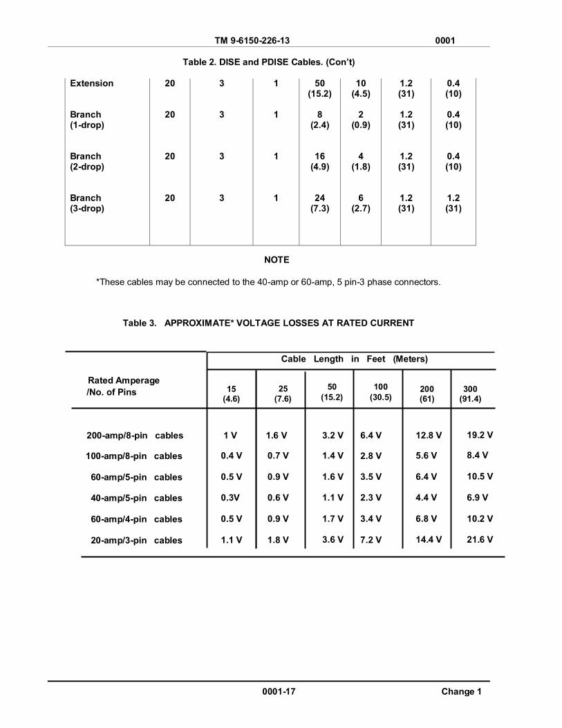
Table 2. DISE and PDISE Cables. (Con’t)
Extension Branch (1-drop) Branch (2-drop) Branch (3-drop)
20
20
20
20
3 3 3 3
1
1
1
1
50 (15.2)
8
(2.4)
16 (4.9)
24 (7.3)
10 (4.5)
2
(0.9)
4 (1.8)
6 (2.7)
1.2 (31)
1.2 (31)
1.2 (31)
1.2 (31)
0.4 (10)
0.4 (10)
0.4 (10)
1.2 (31)
*These cables may be connected to the 40-amp or 60-amp, 5 pin-3 phase connectors.
Table 3. APPROXIMATE* VOLTAGE LOSSES AT RATED CURRENT
Cable Length in Feet (Meters)
Rated Amperage /No. of Pins
200-amp/8-pin cables
100-amp/8-pin cables 60-amp/5-pin cables 40-amp/5-pin cables 60-amp/4-pin cables 20-amp/3-pin cables
1 V 0.4 V 0.5 V 0.3V 0.5 V 1.1 V
1.6 V
0.7 V 0.9 V 0.6 V
0.9 V
1.8 V
3.2 V 1.4 V 1.6 V 1.1 V 1.7 V 3.6 V
6.4 V 2.8 V 3.5 V 2.3 V
3.4 V 7.2 V
12.8 V 5.6 V 6.4 V 4.4 V 6.8 V 14.4 V
19.2 V 8.4 V 10.5 V 6.9 V 10.2 V 21.6 V
50 (15.2)
25 (7.6)
15 (4.6)
100 (30.5)
200 (61)
300 (91.4)
NOTE

TM 9-6150-226-13 0001
Change 1 0001-18
EQUIPMENT CONFIGURATION
Single-Phase System: The M60 and M60 A/P 60-amp, single phase electrical distribution system (See Figure 6) can be used as a stand-alone system with the following provisions:
(a) The total load must not exceed 7.2 kW.
(b) The generator selected must be capable of supporting the total load.
(c) Individual branch circuit loads must not exceed 2.4 kW. Three of the six outputs, carrying a maximum load, can be used at the same time.
Three-Phase Systems:
1. M200 and M200 A/P. The 200-amp, 3-phase electrical feeder system (Figure 3) can be used as a stand-alone system with the following provisions:
(a) The total load must not exceed 72 kW.
(b) The generator selected must be capable of supporting the total load.
(c) Individual branch circuit output loads must not exceed:
(1) 36 kW for the 100-amp. 3-phase branch circuits. Two of the three outputs, carrying maximum load, can-be used at the same time.
(2) 21.6 kW for the 60-amp, 3-phase branch circuits. Three of the four outputs, carrying a maximum load, can be used at the same time.
(3) 2.4 kW for the 20-amp, single-phase branch circuit.
2. M100 and M100 A/P. The 100-amp, 3-phase electrical feeder system (Figure 4) can be used as a stand-alone system with the following provisions:
(a) The total load must not exceed 36 kW.
(b) The generator selected must be capable of supporting the total load.
(c) Individual branch circuit output loads must not exceed:
(1) 36 kW for the 100-amp, 3-phase feed-through circuit. This uses the total
system capacity and no other outputs can be used.
(2) 21.6 kW for the 60-amp, 3-phase branch circuits. Only one of the two outputs, carrying maximum load, can be used at the same time.
(3) 14.4 kW for the 40-amp, 3-phase branch circuits. Both outputs, carrying maximum load, can be used at the same time.
(4) 2.4 kW for the 20-amp, single-phase circuits. Both outputs, carrying maximum load, can be used at the same time.
TM 9-6150-226-13 0001
0001-19 Change 1
3. M40 and M40 A/P. The 40-amp, 3-phase electrical distribution system (Figure 5) can be used as a stand-alone system with the following provisions:
(a) The total load must not exceed 14.4 kW.
(b) The generator selected must be capable of supporting the total load.
(c) Individual branch circuit output loads must not exceed:
(1) 14.4 kW for the 40-amp, 3-phase feed-through circuit. This uses the total system capacity and no other outputs can he used.
(2) 2.4 kW for the 20-amp, single-phase branch circuits. Six of the twelve outputs, carrying maximum load, can be used at the same time.
M46 Electrical Utility Assembly. The M46 (Figure 7) can be used with any DISE/PDISE system to provide the user with lighting and 120 VAC duplex receptacle outlets.
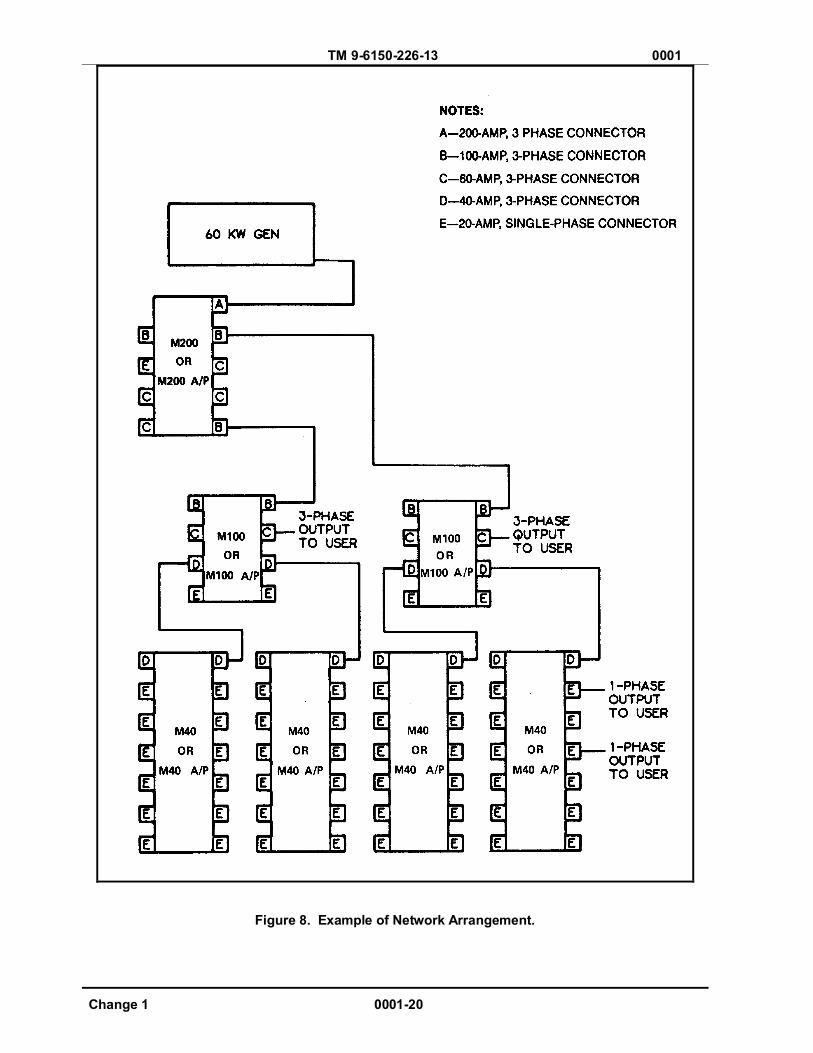
Networking. Figure 8 is an example of one possible network arrangement. The 3-phase systems are used for networking with the following provisions:
(a) The total load must not exceed the capacity of the largest distribution center connected between the generator and the rest of the network.
(b) The generator selected must be capable of supporting the total load.
(c) Individual branch systems must not exceed the capacity of the branch distribution center.
TM 9-6150-226-13 0001
Change 1 0001-20
Figure 8. Example of Network Arrangement.

TM 9-6150-226-13 0001
0001-21/22 Blank Change 1
Generator –DISE/PDISE Configuration. Figure 9 is a list of examples for pairing generator sets with equipment. Refer to FM 20-31, Electrical Power Generation in the Field, for generator selection.
Figure 9. Pairing of Gen Set with Equipment PRINCIPLES OF OPERATION.
The generator supplies electrical power to the DISE and PDISE systems. The DISE and PDISE systems distribute electrical power through circuit breakers and cables to the user electrical equipment. The circuit breakers mounted in the feeder/distribution center protect system cables from excessive current flow.
END OF WORK PACKAGE


TM 9-6150226-13 0002
OPERATOR AND FIELD MAINTENANCE MANUAL DISE AND PDISE SYSTEMS
DESCRIPTION AND USE OF OPERATOR’S CONTROLS AND INDICATORS
M200 DISE FEEDER CENTER AND M200 A/P PDISE FEEDER CENTER.
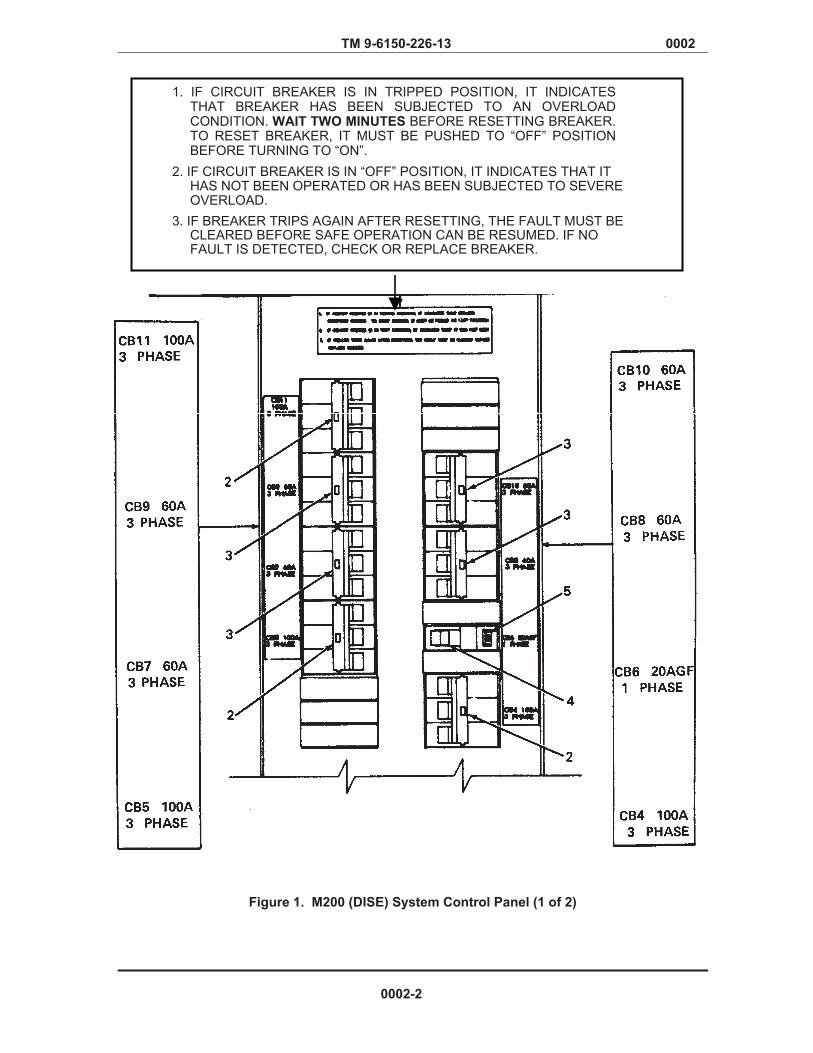
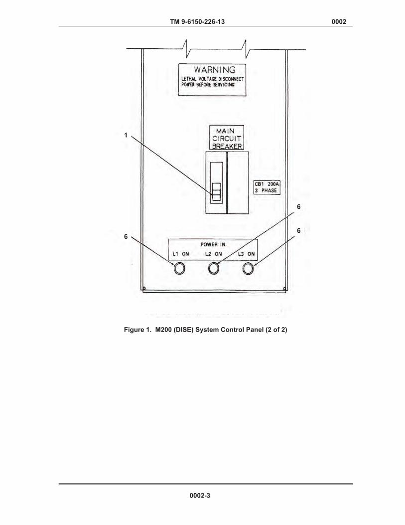
Main Circuit Breaker (CB1). This 3-phase circuit breaker (Figure 1, Item 1) for M200 and (Figure 1, Item 1) for A/P is in series between the 200-amp input connector and the bus bars. This circuit breaker prevents input power to the distribution center from exceeding a total current of 200 amps per phase (72 kW maximum load). This circuit breaker allows the operator to turn off power to all output circuit breakers.
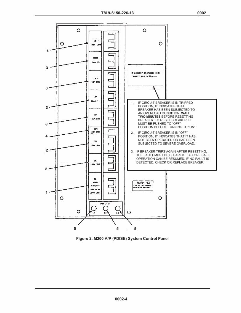
CB4, CB5, and CB11 (100-amp, 3-Phase). Each 3-phase circuit breaker (Figure 1, Item 2) for M200 and (Figure 2, Item 2) for M200 A/P is in series between the bus bars and a 100-amp output connector. These circuit breakers prevent output power to the connectors from exceeding a current of 100 amps per phase (36 kW maximum load). These circuit breakers allow the operator to turn off power to the load circuits.
CB7, CB8, CB9, and C10 (60-amp. 3-Phase). Each 3-phase circuit breaker (Figure 1, Item 3) for M200 and (Figure 2, Item 3) for M200 A/P is in series between the bus bars and a 60-amp output connector. These circuit breakers prevent output power to the connectors from exceeding a current of 60 amps per phase (21.6 kW maximum load). These circuit breakers allow the operator to turn off power to the load circuits.
CB6 (20 amps Ground Fault [GF], Single-Phase). This circuit breaker (Figure 1, Item 4) for M200 is in series between the bus bars and the 20-amp output connector. This circuit breaker prevents output power to the connector from exceeding a current of 20 amps (2.4 kW maximum load), allows the operator to turn off power to the load, and also interrupts the circuits when a current flow occurs in the ground wire.
CB6 (20-amp, Single-Phase). This single-phase circuit breaker (Figure 2, Item 4) for M200 A/P is in series between the bus bars and a 20-amp output connector. This circuit breaker prevents output power to the connector from exceeding a current of 20 amps per phase (2.4 kW maximum load). This circuit breaker also allows the operator to turn off to the load circuit.
Ground Fault Test Switch. This switch (Figure 1, Item 5) for M200 tests the ground fault sensor (trip indication) for the 20A GF circuit breaker. The M200 A/P does not have a ground fault circuit.
L1, L2, and L3 Phase Indicator Lights. These lights (Figure 1, Item 6) for M200 and (Figure 2, Item 5) for M200 A/P are connected between neutral and each phase. When electrical power is being supplied to the feeder center, the lights will illuminate.
Identification Plates. Figure 1 and 2 shows the location of various data plates on the Control panel of M200 equipment. Figure 10 shows the location of the cable connections for the M200 equipment. Figure 9 shows a ground fault test record which is located on the right side of the control panel on all DISE feeder/distribution centers.
0002-1
TM 9-6150-226-13 0002
Figure 1. M200 (DISE) System Control Panel (1 of 2)
1. IF CIRCUIT BREAKER IS IN TRIPPED POSITION, IT INDICATES THAT BREAKER HAS BEEN SUBJECTED TO AN OVERLOAD CONDITION. WAIT TWO MINUTES BEFORE RESETTING BREAKER. TO RESET BREAKER, IT MUST BE PUSHED TO “OFF” POSITION BEFORE TURNING TO “ON”.
2. IF CIRCUIT BREAKER IS IN “OFF” POSITION, IT INDICATES THAT IT HAS NOT BEEN OPERATED OR HAS BEEN SUBJECTED TO SEVERE OVERLOAD.
3. IF BREAKER TRIPS AGAIN AFTER RESETTING, THE FAULT MUST BE CLEARED BEFORE SAFE OPERATION CAN BE RESUMED. IF NO FAULT IS DETECTED, CHECK OR REPLACE BREAKER.
0002-2
Verified Draft
TM 9-6150-226-13 0002
Figure 1. M200 (DISE) System Control Panel (2 of 2)
1
6
6
6
0002-3
Verified Draft
TM 9-6150-226-13 0002
Figure 2. M200 A/P (PDISE) System Control Panel
1. IF CIRCUIT BREAKER IS IN TRIPPED POSITION, IT INDICATES THAT BREAKER HAS BEEN SUBJECTED TO AN OVERLOAD CONDITION. WAIT TWO MINUTES BEFORE RESETTING BREAKER. TO RESET BREAKER, IT MUST BE PUSHED TO “OFF” POSITION BEFORE TURNING TO “ON”.
2. IF CIRCUIT BREAKER IS IN “OFF”
POSITION, IT INDICATES THAT IT HAS NOT BEEN OPERATED OR HAS BEEN SUBJECTED TO SEVERE OVERLOAD.
3. IF BREAKER TRIPS AGAIN AFTER RESETTING,
THE FAULT MUST BE CLEARED BEFORE SAFE OPERATION CAN BE RESUMED. IF NO FAULT IS DETECTED, CHECK OR REPLACE BREAKER.
4
5 5 5
0002-4

TM 9-6150-226-13 0002
M100 DISE FEEDER CENTER AND M100 A/P PDISE FEEDER CENTER.
Main Circuit Breaker CB1 (100-amp, 3-Phase). This 3-phase circuit breaker (Figure 3, Item 1) for M100 and (Figure 4, Item 1) for M100 A/P is in series between the 100-amp input connector and the bus bars. This circuit breaker prevents input power to the distribution center from exceeding a total current of 100 amps per phase (36 kW maximum load). This circuit breaker also allows the operator to turn off power to all output circuit breakers.
CB3 and CB6 (60-amp, 3-Phase). Each 3-phase circuit breaker (Figure 3, Item 2) for M100 and (Figure 4, Item 2) for M100 A/P is in series between the bus bars and a 60-amp output connector. These circuit breakers prevent output power to the connectors from exceeding a current of 60 amps per phase (21.6 kW maximum load). These circuit breakers also allow the operator to turn off power to the load circuits.
CB4 and CB5 (40-amp, 3-Phase). Each 3-phase circuit breaker (Figure 3, Item 3) for M100 and (Figure 4, Item 3) for M100 A/P is in series between the bus bars and a 40-amp output connector. These circuit breakers prevent output power to the connectors from exceeding a current of 40 amps per phase (14.4 kW maximum load). These circuit breakers allow the operator to turn off power to the load circuits.
CB7 and CB8 Ground Fault [GF], Single-Phase). Each single-phase circuit breaker (Figure 3, Item 4) for M100 is in series between the bus bars and a 20-amp output connector. These circuit breakers prevent output power to the connectors from exceeding a current of 20 amps (2.4 kW maximum load), allows the operator to turn power off to the load, and interrupt the circuit when a current flow occurs in the ground wire.
CB7 and CB8 (20-amp. Single-Phase). Each single-phase circuit breaker (Figure 4, Item 7) for M100 A/P is in series between the bus bars and a 20-amp output connector. These circuit breakers prevent output power to the connectors from exceeding a current of 20 amps per phase (2.4 kW maximum load). These circuit breakers also allow the operator to turn off to the load circuits.
Ground Fault Test Switch. These switches (Figure 3, Item 5) for the M100 test the ground fault sensor (trip indication) for the 20A GF circuit breakers. The M100 A/P does not have a ground fault circuit.
L1, L2, and L3 Phase Indicator Lights. These lights (Figure 3, Item 6) for M100 and (Figure 4, Item 6) for M100 A/P are connected between neutral and each phase. When electrical power is being supplied to the feeder center, the lights will illuminate.
Identification Plates. Figure 3 and 4 shows the location of various data plates on the control panel of M100 equipment. Figure 11 shows the location of the cable connection for the M100 equipment. Figure 9 shows a ground fault test record which is located on the right side of the control panel on all DISE feeder/distribution centers.
0002-5

Verified Draft
TM 9-6150-226-13 0002
Figure 3. M100 (DISE) System Control Panel
1. IF CIRCUIT BREAKER IS IN TRIPPED POSITION, IT INDICATES THAT BREAKER HAS BEEN SUBJECTED TO AN OVERLOAD CONDITION. WAIT TWO MINUTES BEFORE RESETTING BREAKER. TO RESET BREAKER, IT MUST BE PUSHED TO “OFF” POSITION BEFORE TURNING TO “ON”. 2. IF CIRCUIT BREAKER IS IN “OFF” POSITION, IT INDICATES THAT IT HAS NOT BEEN OPERATED OR HAS BEEN SUBJECTED TO SEVERE OVERLOAD. 3. IF BREAKER TRIPS AGAIN AFTER RESETTING, THE FAULT MUST BE CLEARED BEFORE SAFE OPERATION CAN BE RESUMED. IF NO FAULT IS DETECTED, CHECK OR REPLACE BREAKER.
0002-6

Verified Draft
TM 9-6150-226-13 0002
1. IF CIRCUIT BREAKER IS IN TRIPPED POSITION, IT INDICATES THAT BREAKER HAS BEEN SUBJECTED TO AN OVERLOAD CONDITION.WAIT TWO MINUTES BEFORE RESETTING BREAKER. TO RESET BREAKER, IT MUST BE PUSHED TO “OFF” POSITION BEFORE TURNING TO “ON”. 2. IF CIRCUIT BREAKER IS IN “OFF” POSITION, IT INDICATES THAT IT HAS NOT BEEN OPERATED OR HAS BEEN SUBJECTED TO SEVERE OVERLOAD. 3. IF BREAKER TRIPS AGAIN AFTER RESETTING, THE FAULT MUST BE CLEARED BEFORE SAFE OPERATION CAN BE RESUMED. IF NO FAULT IS DETECTED, CHECK OR REPLACE BREAKER.
Figure 4. M100 A/P (PDISE) System Control Panel
4
4
5 5 5
0002-7

TM 9-6150-226-13 0002
M40 DISE DISTRIBUTION CENTER AND M40 A/P PDISE DISTRIBUTION CENTER.
Main Circuit Breaker CB1 (40-amp, 3-Phase). This 3-phase circuit breaker (Figure 5, Item 1) for the M40 and (Figure 6, Item 1) for M40 A/P is in series between the 40-amp input connector and the bus bars. This circuit breaker prevents input power to the distribution center from exceeding a total current of 40 amps per phase (14.4 kW maximum load). This circuit breaker allows the operator to turn off power to all output circuit breakers.
CB4, CB6, CB10, CB12, CB14 and CB14 (20-amp, Single-Phase). Each single-phase circuit breaker (Figure 5, Item 2) for M40 is in series between the bus bars and a 20-amp output connector. These circuit breakers prevent output power to the connectors from exceeding a current of 20 amps per phase (2.4 kW maximum load). These circuit breakers also allow the operator to turn off power to the load circuits.
CB3, CB5, CB7, CB9, CB11, and CB13 (20-amp Ground Fault [GF], Single-Phase). Each single-phase circuit breaker (Figure 5, Item 3) for the M40 is in series between the bus bars and a 20-amp output connector. These circuit breakers prevent output power to the connectors from exceeding a current of 20 amps (2.4 kW maximum load), allows the operator to turn power off to the load, and also interrupts the circuit when a current flow occurs in the ground wire.
CB3 through CB14 (20-amp, Single Phase). Each single-phase circuit breaker (Figure 6, Item 3) for M40 A/P is in series between the bus bars and a 20- amp output connector. These circuit breakers prevent output power to the connectors from exceeding a current of 20 amps per phase (2.4 kW maximum load). These circuit breakers also allow the operator to turn off to the load circuits.
Ground Fault Test Switch. These switches (Figure 5, Item 4) for M40 test the ground fault sensors (trip on) for the 20 AFG circuit breakers. The M40 A/P does not have a ground fault circuit.
L1, L2, and L3 Phase Indicator Lights. These lights (Figure 5, Item 5) for M40 and (Figure 2, Item 2) for M40 A/P are connected between neutral and each phase. When electrical power is being supplied to the distribution center, the lights will illuminate.
Identification Plates. Figure 5 and 6 shows the location of various data plates on the control panel of M40 equipment. Figure 12 shows the location of the cable connections for the M40 equipment. Figure 9 shows a ground fault test record which is located on the right side of the control panel on all DISE feeder/distribution centers.
0002-8

TM 9-6150-226-13 0002
1. IF CIRCUIT BREAKER IS IN TRIPPED POSITION, IT INDICATES THAT BREAKER HAS BEEN SUBJECTED TO AN OVERLOAD CONDITION. WAIT TWO MINUTES BEFORE RESETTING BREAKER. TO RESET BREAKER, IT MUST BE PUSHED TO “OFF” POSITION BEFORE TURNING TO “ON”.
2. IF CIRCUIT BREAKER IS IN “OFF” POSITION, IT INDICATES THAT IT HAS NOT BEEN OPERATED OR HAS BEEN SUBJECTED TO SEVERE OVERLOAD.
3. IF BREAKER TRIPS AGAIN AFTER RESETTING, THE FAULT MUST BE CLEARED BEFORE
SAFE OPERATION CAN BE RESUMED. IF NO FAULT IS DETECTED, CHECK OR REPLACE BREAKER.
Figure 5. M40 (DISE) System Control Panel
0002-9

Verified Draft
TM 9-6150-226-13 0002
1. IF CIRCUIT BREAKER IS IN TRIPPED POSITION, IT INDICATES THAT BREAKER HAS BEEN SUBJECTED TO AN OVERLOAD CONDITION. WAIT TWO MINUTES BEFORE RESETTING BREAKER. TO RESET BREAKER, IT MUST BE PUSHED TO “OFF” POSITION BEFORE TURNING TO “ON”.
2. IF CIRCUIT BREAKER IS IN “OFF” POSITION, IT INDICATES THAT IT HAS NOT BEEN OPERATED OR HAS BEEN SUBJECTED TO SEVERE OVERLOAD.
3. IF BREAKER TRIPS AGAIN AFTER RESETTING, THE FAULT MUST BE CLEARED BEFORE
SAFE OPERATION CAN BE RESUMED. IF NO FAULT IS DETECTED, CHECK OR REPLACE BREAKER.
Figure 6. M40 A/P (PDISE) System Control Panel
2 2 2
3
3 3
3
3
3 3
3
3
3
3
3
0002-10
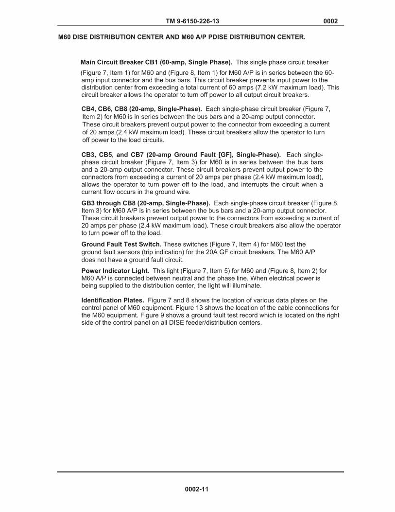
TM 9-6150-226-13 0002
M60 DISE DISTRIBUTION CENTER AND M60 A/P PDISE DISTRIBUTION CENTER.
Main Circuit Breaker CB1 (60-amp, Single Phase). This single phase circuit breaker (Figure 7, Item 1) for M60 and (Figure 8, Item 1) for M60 A/P is in series between the 60-amp input connector and the bus bars. This circuit breaker prevents input power to the distribution center from exceeding a total current of 60 amps (7.2 kW maximum load). This circuit breaker allows the operator to turn off power to all output circuit breakers.
CB4, CB6, CB8 (20-amp, Single-Phase). Each single-phase circuit breaker (Figure 7, Item 2) for M60 is in series between the bus bars and a 20-amp output connector. These circuit breakers prevent output power to the connector from exceeding a current of 20 amps (2.4 kW maximum load). These circuit breakers allow the operator to turn off power to the load circuits.
CB3, CB5, and CB7 (20-amp Ground Fault [GF], Single-Phase). Each single-phase circuit breaker (Figure 7, Item 3) for M60 is in series between the bus bars and a 20-amp output connector. These circuit breakers prevent output power to the connectors from exceeding a current of 20 amps per phase (2.4 kW maximum load), allows the operator to turn power off to the load, and interrupts the circuit when a current flow occurs in the ground wire.
GB3 through CB8 (20-amp, Single-Phase). Each single-phase circuit breaker (Figure 8, Item 3) for M60 A/P is in series between the bus bars and a 20-amp output connector. These circuit breakers prevent output power to the connectors from exceeding a current of 20 amps per phase (2.4 kW maximum load). These circuit breakers also allow the operator to turn power off to the load.
Ground Fault Test Switch. These switches (Figure 7, Item 4) for M60 test the ground fault sensors (trip indication) for the 20A GF circuit breakers. The M60 A/P does not have a ground fault circuit.
Power Indicator Light. This light (Figure 7, Item 5) for M60 and (Figure 8, Item 2) for M60 A/P is connected between neutral and the phase line. When electrical power is being supplied to the distribution center, the light will illuminate. Identification Plates. Figure 7 and 8 shows the location of various data plates on the control panel of M60 equipment. Figure 13 shows the location of the cable connections for the M60 equipment. Figure 9 shows a ground fault test record which is located on the right side of the control panel on all DISE feeder/distribution centers.
0002-11
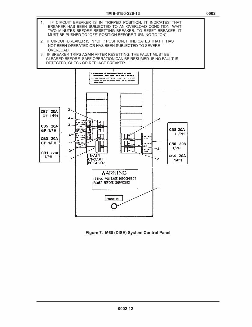
Verified Draft
TM 9-6150-226-13 0002
Figure 7. M60 (DISE) System Control Panel
1. IF CIRCUIT BREAKER IS IN TRIPPED POSITION, IT INDICATES THAT BREAKER HAS BEEN SUBJECTED TO AN OVERLOAD CONDITION. WAIT TWO MINUTES BEFORE RESETTING BREAKER. TO RESET BREAKER, IT MUST BE PUSHED TO “OFF” POSITION BEFORE TURNING TO “ON”.
2. IF CIRCUIT BREAKER IS IN “OFF” POSITION, IT INDICATES THAT IT HAS NOT BEEN OPERATED OR HAS BEEN SUBJECTED TO SEVERE OVERLOAD.
3. IF BREAKER TRIPS AGAIN AFTER RESETTING, THE FAULT MUST BE CLEARED BEFORE SAFE OPERATION CAN BE RESUMED. IF NO FAULT IS DETECTED, CHECK OR REPLACE BREAKER.
0002-12
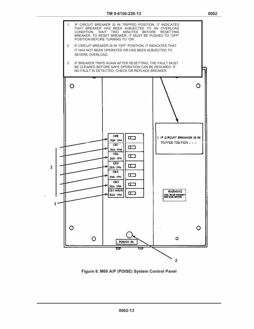
Verified Draft
TM 9-6150-226-13 0002
Figure 8. M60 A/P (PDISE) System Control Panel
3
2
1. IF CIRCUIT BREAKER IS IN TRIPPED POSITION, IT INDICATES THAT BREAKER HAS BEEN SUBJECTED TO AN OVERLOAD CONDITION. WAIT TWO MINUTES BEFORE RESETTING BREAKER. TO RESET BREAKER, IT MUST BE PUSHED TO “OFF” POSITION BEFORE TURNING TO “ON”.
2. IF CIRCUIT BREAKER IS IN “OFF” POSITION, IT INDICATES THAT
IT HAS NOT BEEN OPERATED OR HAS BEEN SUBJECTED TO SEVERE OVERLOAD.
3. IF BREAKER TRIPS AGAIN AFTER RESETTING, THE FAULT MUST BE CLEARED BEFORE SAFE OPERATION CAN BE RESUMED. IF NO FAULT IS DETECTED, CHECK OR REPLACE BREAKER.
0002-13
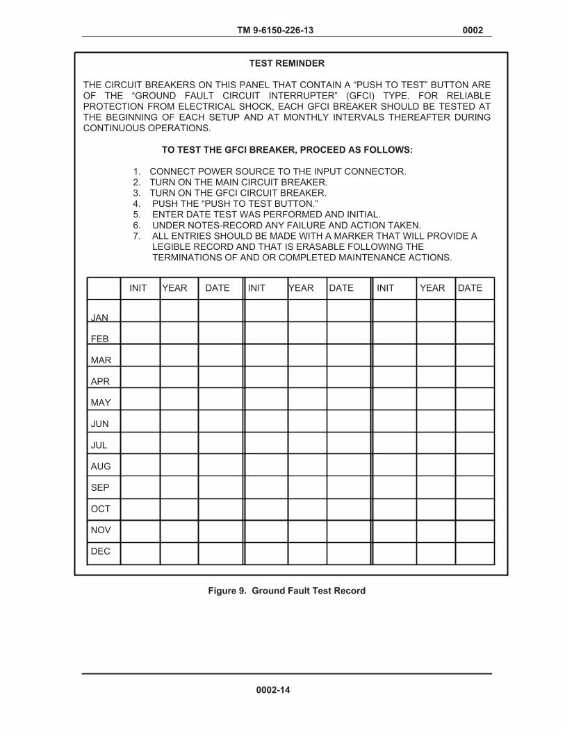
TM 9-6150-226-13 0002
TEST REMINDER THE CIRCUIT BREAKERS ON THIS PANEL THAT CONTAIN A “PUSH TO TEST” BUTTON ARE OF THE “GROUND FAULT CIRCUIT INTERRUPTER” (GFCI) TYPE. FOR RELIABLE PROTECTION FROM ELECTRICAL SHOCK, EACH GFCI BREAKER SHOULD BE TESTED AT THE BEGINNING OF EACH SETUP AND AT MONTHLY INTERVALS THEREAFTER DURING CONTINUOUS OPERATIONS.
TO TEST THE GFCI BREAKER, PROCEED AS FOLLOWS:
1. CONNECT POWER SOURCE TO THE INPUT CONNECTOR. 2. TURN ON THE MAIN CIRCUIT BREAKER. 3. TURN ON THE GFCI CIRCUIT BREAKER. 4. PUSH THE “PUSH TO TEST BUTTON.” 5. ENTER DATE TEST WAS PERFORMED AND INITIAL. 6. UNDER NOTES-RECORD ANY FAILURE AND ACTION TAKEN. 7. ALL ENTRIES SHOULD BE MADE WITH A MARKER THAT WILL PROVIDE A
LEGIBLE RECORD AND THAT IS ERASABLE FOLLOWING THE TERMINATIONS OF AND OR COMPLETED MAINTENANCE ACTIONS.
INIT YEAR DATE INIT YEAR DATE INIT YEAR DATE
JAN
FEB
MAR
APR
MAY
JUN
JUL
AUG
SEP
OCT
NOV
DEC
Figure 9. Ground Fault Test Record
0002-14
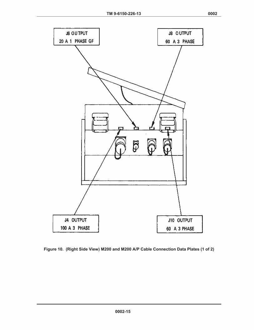
Verified Draft
TM 9-6150-226-13 0002
Figure 10. (Right Side View) M200 and M200 A/P Cable Connection Data Plates (1 of 2)
0002-15
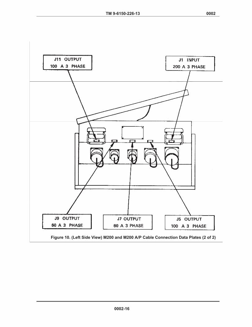
Verified Draft
TM 9-6150-226-13 0002
Figure 10. (Left Side View) M200 and M200 A/P Cable Connection Data Plates (2 of 2)
0002-16

Verified Draft
TM 9-6150-226-13 0002
Figure 11. (Right Side View) M100 and M100 A/P Cable Connection Data Plates (1 of 2)
0002-17

Verified Draft
TM 9-6150-226-13 0002
Figure 11. (Left View) M100 and M100 A/P Cable Connection Data Plates (2 of 2)
0002-18
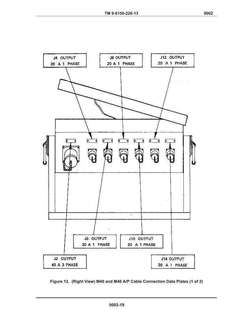
Verified Draft
TM 9-6150-226-13 0002
Figure 12. (Right View) M40 and M40 A/P Cable Connection Data Plates (1 of 2)
0002-19

Verified Draft
TM 9-6150-226-13 0002
Figure 12. (Left View) M40 and M40 A/P Cable Connection Data Plates (2 of 2)
0002-20
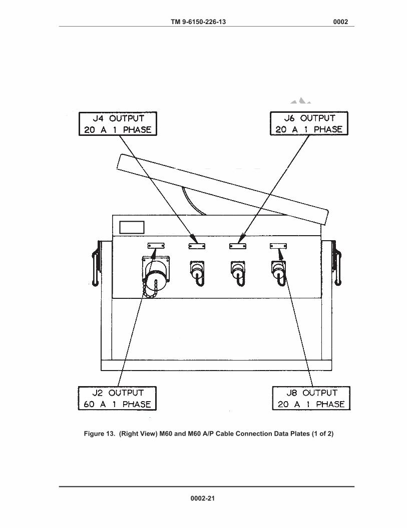
Verified Draft
TM 9-6150-226-13 0002
Figure 13. (Right View) M60 and M60 A/P Cable Connection Data Plates (1 of 2)
0002-21
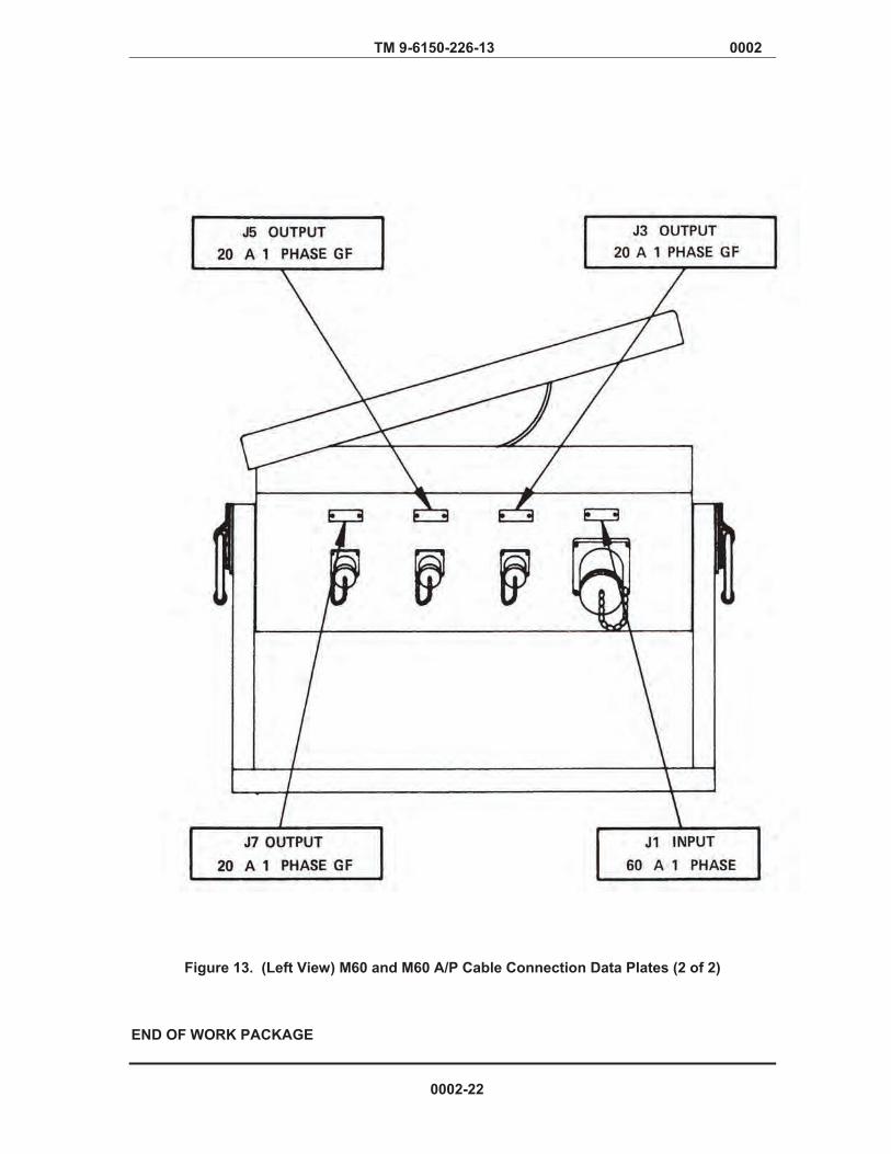
Verified Draft
TM 9-6150-226-13 0002
Figure 13. (Left View) M60 and M60 A/P Cable Connection Data Plates (2 of 2)
END OF WORK PACKAGE
0002-22

Chapter 2
Operator Level Instructions

TM 9-6150-226-13 0003
OPERATOR AND FIELD MAINTENANCE MANUAL DISE AND PDISE SYSTEMS
OPERATION UNDER USUAL CONDITIONS
INITIAL SETUP:
Tools and Special Tools Personnel RequiredOne
Materials and Parts ReferencesNone FM 20-31 DA Form 2404 Equipment Conditions
PRELIMINARY SETUP
WARNING
Components of this system are heavy and may be awkward to handle. Use correct lifting procedures
and/or assistance from personnel to avoid injury.
Considerations and calculations for field load equipment may be complicated. The Commander should appoint a qualified soldier to plan the power network. The soldier shall consult and plan the power network with personnel (MOS 52D) familiar with electrical power distribution principles and calculations when available to the field. Assembly of Power Distribution Plan 1. Begin by creating an analysis of electrical equipment needs in the particular field application, starting with the consuming end of the system and work back to the power source. The unit’s TOE/MTOE will dictate the quantity and size of your generator set(s) and DISE or PDISE equipment, but various exercises may allow a selection of equipment to support the mission. 2. Determine special considerations for grounding and routing of cables. You should also know general locations of the power source and the vehicles, tents, communication vans, etc. that are being provided power. 3. Become familiar with tactical or other restrictions (if any) on locating the power source(s) relative to tents, shelters, and other power consuming equipment. 4. Prepare a power distribution plan based on the above analysis, to include wattage, amps, and type of power needed (single and three phase). Try to use the least amount of generators possible using FM 20-31 as a guide as well.
0003-1
NOTE
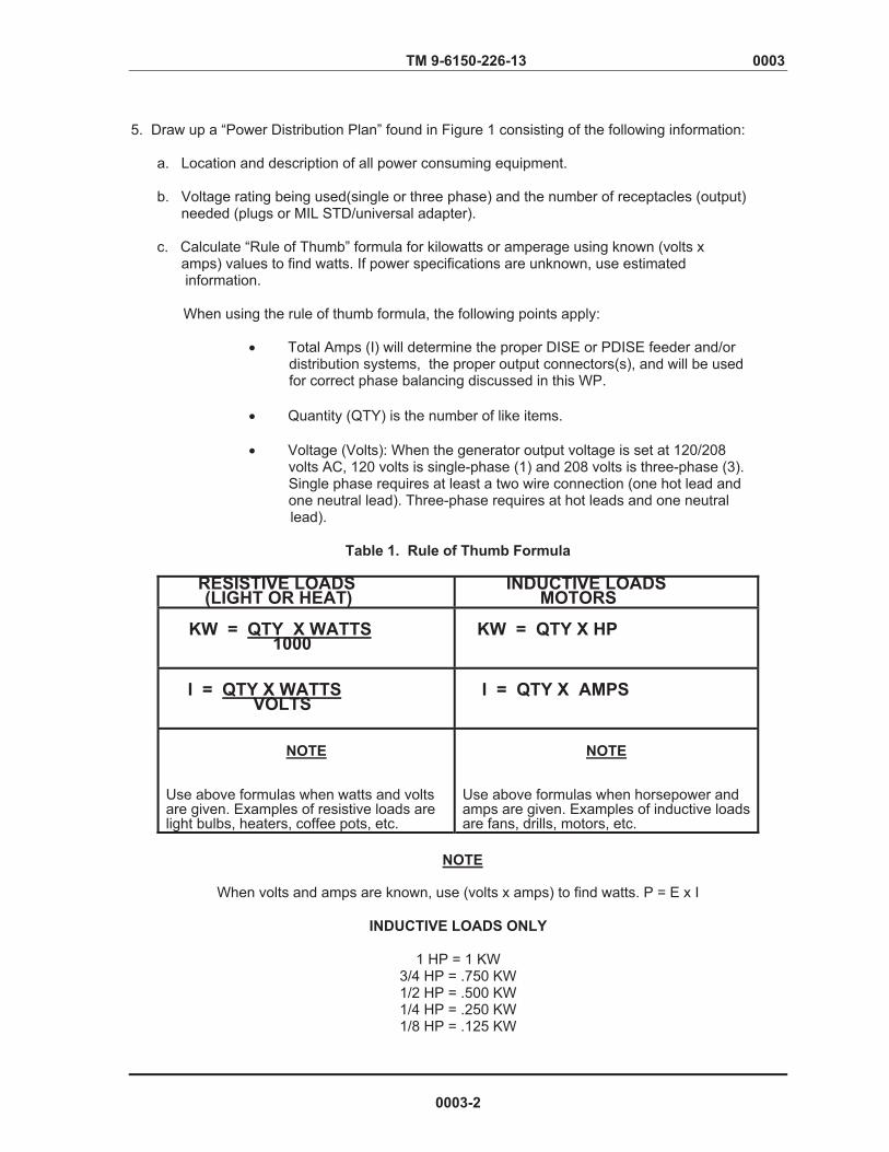
TM 9-6150-226-13 0003 5. Draw up a “Power Distribution Plan” found in Figure 1 consisting of the following information:
a. Location and description of all power consuming equipment.
b. Voltage rating being used(single or three phase) and the number of receptacles (output) needed (plugs or MIL STD/universal adapter). c. Calculate “Rule of Thumb” formula for kilowatts or amperage using known (volts x amps) values to find watts. If power specifications are unknown, use estimated information.
When using the rule of thumb formula, the following points apply:
� Total Amps (I) will determine the proper DISE or PDISE feeder and/or distribution systems, the proper output connectors(s), and will be used for correct phase balancing discussed in this WP.
� Quantity (QTY) is the number of like items.
� Voltage (Volts): When the generator output voltage is set at 120/208
volts AC, 120 volts is single-phase (1) and 208 volts is three-phase (3). Single phase requires at least a two wire connection (one hot lead and one neutral lead). Three-phase requires at hot leads and one neutral
lead).
Table 1. Rule of Thumb Formula
RESISTIVE LOADS (LIGHT OR HEAT)
INDUCTIVE LOADS MOTORS
KW = QTY X WATTS 1000
KW = QTY X HP
I = QTY X WATTS VOLTS
I = QTY X AMPS
NOTE
Use above formulas when watts and volts are given. Examples of resistive loads are light bulbs, heaters, coffee pots, etc.
NOTE
Use above formulas when horsepower and amps are given. Examples of inductive loadsare fans, drills, motors, etc.
When volts and amps are known, use (volts x amps) to find watts. P = E x I
INDUCTIVE LOADS ONLY
1 HP = 1 KW 3/4 HP = .750 KW 1/2 HP = .500 KW 1/4 HP = .250 KW 1/8 HP = .125 KW
0003-2
NOTE

TM 9-6150-226-13 0003
DISE and PDISE can only be used with generators rated at 120/208 VAC. All other ratings will require a different type of generator set.
d. Add up total amounts down at the bottom of the figure.
Required Receptacle Total Total 120 V/1-ph 208 V/3-ph Kilowatts Amps
MIL STD/
Area/Item Plug(s) Univ Adapter 1-ph 3-ph
Tent #1 1.) Electric drill 120 V/800W 1 .800 6.6 2.) Electric grinder 120 V/7.5 amps 1 .900 7.5 3.) Sander 120 V/450W 1 .450 3.75 4.) Radio set 120 V/180W 1 .180 1.5 5.) Lights 120 V/60W ea 6 6 .360 6.) Welder 208 V/1 1/2HP/4.5 amps 1 1.500 4.5
TOTAL FOR TENT #1 10 1 4.190 22.35 4.5
Tent #2
1.) Electric heater 120 V/10.8 amps 1 1.300 10.8 2.) Radio transceiver 120 V/1000W 1 1.000 8.3 3.) Light set 120 V.60W ea 1 .360 3.0
TOTAL FOR TENT #2 3 2.660 22.1
Tent #3
1.) X-Ray field 120 V/5 amps 1 .600 5.0 2.) Film processor 120 V/120W 1 .120 1.0 3.) Suction field 120 V/140W 1 .140 1.2 4.) Prophylaxis field 120 V/1500W 1 .150 1.3 5.) Surgery lamp 120 V/10 amps 1 1.200 10.0 6.) Light set 120 V/60W ea 1 .480 4.0
TOTAL FOR TENT #3 6 2.690 22.5
TOTAL REQUIREMENTS 19 1 9.540 66.95 4.5
Figure 1. Power Distribution Plan Example
0003-3
NOTE

TM 9-6150-226-13 0003
Generator Selection
6. Choose the proper power source for your mission based on the power analysis total column.
If connecting DISE/PDISE equipment to power sources that are paralleled, ensure that connections are made to the switching device between the paralleled generators
Remember that not all power devices will likely be energized at the same time. Therefore, you should determine the maximum power demand during actual operation. These are things to consider when choosing the appropriate DISE/PDISE - power configuration:
� The M40 and M60 distribution systems can provide single phase output, but cannot be used in series or be cabled to each other. The M60 system is a stand alone single phase distribution system. You will have to determine the number, type, and location of the M40 and/or M60 amp distribution systems needed. � When using the M40 distribution system, determine the number and location of M100-amp and/or M200-amp feeder systems, if any. It is more efficient to locate the power consuming equipment as close to the power source as possible, thereby minimizing the need for feeder systems. Refer to WP 0001 for pairing of the distribution systems to the appropriate sized generator. � The 100-amp feeder system can be used with two or more M40 distribution
systems, and the M200-amp feeder system with two or more 100-amp feeder systems.
� The feeder systems can also be used in a stand alone mode to feed power
directly to multiple existing pre-wired circuits that require 40 three-phase or 60-amp input power, such as large shelters or systems that have the proper military standard and 120 VAC systems.
� Ensure that the M46 electrical utility assemblies, which provide lighting AC duplex receptacles, are connected only to DISE/PDISE feeder or distribution systems. The M46 does not have built in fuse or circuit breaker protection.
DISE/PDISE Selection
7. Determine the appropriate feeder/distribution system(s) needed which will handle the total amperage required for your mission.
When selecting the DISE/PDISE equipment, you cannot exceed the total amperage rating of the largest feeder/distribution center. The following must be determined when selecting your DISE/PDISE equipment:
� Quantity of M46 Electrical Utility Assemblies needed in each area. � Quantity of three phase and single phase output connectors used.
� Quantity of Universal Adapters needed for equipment not compatible with DISE/PDISE equipment.
0003-4
NOTE

TM 9-6150-226-13 0003
A
Figure 1 determined that one 40-amp system was needed. It is capable of one three-phase and twelve single-phase outputs. Six single-phase output connectors and one three-phase connector on the M40 or M40 A/P will be used to connect all the loads. One M46 Electrical Utility Assembly was determined to be needed to provide illumination and sufficient receptacles to accommodate all the loads. One Universal Adapter will be needed to accommodate the welder. Figure 2 shows the layout of the distribution plan.
Figure 2. Example of Power Distribution Layout
A - PIGTAIL CABLEB - 40/60 AMP SERVICE/FEEDER CABLES C – 20-AMP EXTENSION CABLES D – 20 AMP BRANCH CIRCUIT CABLES E – UNIVERSAL ADAPTER F – DUPLEX RECEPTACLES
10 kW GENERATOR
0003-5
NOTE

TM 9-6150-226-13 0003 Phase Balancing
8. Make a phase balancing table similar to one used in Figure 3. If the DISE/PDISE equipment for your particular field situation uses a three-phase input (M200, 200 A/P, M100, M100 A/P, M40 or M40 A/P system) and single-phase output is required, you will have to allow for phase balancing. Three-phase loads are self-balancing and should be connected first. Refer to Table 2 to determine which output connector should connect to which load for each center.
Each branch circuit cable load must not exceed 2.4 kW or 20 amps (120V x 20 amps – 2400 watts). Each service/feeder cable load must not exceed the kW rating (or amperage rating) of the circuit breaker supporting that load. Table 3 lists the maximum loads for each feeder/distribution center based on output connectors used. Any combination of output connectors can be used as long as the total load does not exceed the capacity of the feeder/distribution center and the load is balanced.
The M40 and M40 A/P is capable of 40-amps per phase, 40-amps on L1, 40-amps on L2, and 40-amps on L3.
Distribute the single-phase loads so they are balanced within 10 percent of each other. Phase imbalances greater than 10 percent may cause damage to the generator set.
Figure 3. Example of Load Assignments for Three/Single Phase Output
Connectors of the M40 or M40 A/P.
9. Connect all three phase loads first.
10. Connect the largest single phase loads.
11. Connect the next largest single-phase load to the phase with the least amperage. 12. Continue connecting the single-phase loads, largest to smallest until all loads are connected.
0003-6
NOTE
CAUTION
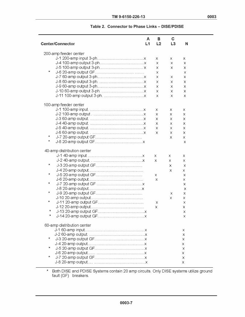
Verified Draft
TM 9-6150-226-13 0003
Table 2. Connector to Phase Links – DISE/PDISE
0003-7

Verified Draft
TM 9-6150-226-13 0003
Table 3. Feeder/Distribution Center Output Connector Loads
Cable Selection/Routing/Connection 13. Choose the appropriate cable(s) based on the distance(s) between the location selected for the generator set, the distribution center, and the tents.
Remember, the longer the cable, the greater the voltage loss at the user’s end. For maximum efficiency, keep the total cable lengths between the generator set and the user equipment under 300 feet (91.44 meters). If the user equipment is too sensitive to voltage loss, you may have to use shorter cables.
WARNING
High voltage is present in this system. DISE and PDISE supports equipment using 120/208 VAC. Do not submerge cable connectors in water. Death or severe injury may result.
CAUTION
Take caution when burying cables which cross roadways. DISE and PDISE cables may be damaged by tactical vehicles.
0003-8
NOTE

TM 9-6150-226-13 0003 14. Route the system cables to avoid vehicle roadways and troop walkways. a. If a cable must cross a roadway, bury the cable (refer to FM 20-31) to protect it from any damage. Do not lay cable connectors in depressions where water can collect. b. Lubricate cables to aid in mating female and male connectors. 15. Connect cables by working outward from user’s equipment to the feeder/distribution center. a. To prevent disconnections and any unsafe conditions, secure branch circuit cables to fixed objects (i.e tents, grounding rods) using given straps. b. Connect required number of duplex receptacle boxes to the branch circuit cable(s). c. Connect any extension cables needed between the branch circuit cable(s) and the appropriate distribution/feeder center output connecter. d. Connect a service/feeder cable of the desired length to the distribution center output connector. Connect the other end to the power consuming device.
If there is a device that does not contain a military standard connector, use the universal adapter described later on in this WP. e. Repeat Steps 15a through d for each additional device. f. Connect the pigtail cable to a service/feeder cable of the desired length. (Refer to Table 2, WP 0001) g. Connect the service/feeder cable to in the input connector of the distribution/feeder center. Generator Connection
High voltage is present in this system. DISE and PDISE support equipment � using 120/208 VAC. Do not connect cables to the generator set with the
power on. Death or severe injury may result.
� Ground the generator set. Death or severe injury may result if you do not properly ground the generator set.
Connect the ground leads (green) of the pigtail cable to the ground terminal � of the generator set. Death or severe injury may result if you do not
properly connect the ground leads to the generator set.
The DISE feeder/distribution centers use ground fault circuit breakers. The neutral and ground of some generator sets must be electrically connected
� with 6-gage wire for the ground fault circuit breakers to function properly. Failure to electrically connect the ground and neutral lugs may result in death or severe injury.
0003-9
NOTE
WARNING
TM 9-6150-226-13 0003 16. Physically check that the generator set is properly grounded. Refer to the appropriate generator set manual for proper grounding procedures.
WARNING High voltage is present in this system. DISE/PDISE support equipment using 120/208 VAC. Do not rely on the color of the wire insulation for phase color-coding. The insulation on the wires inside the cable jacket may vary, depending on the supplier. Wires will be color-coded to designate the phases. Perform a continuity test to verify correct phase designation in accordance with identified color. 17. Connect the pigtail cable to the generator set as follows:
� Black lead (phase A) to L1
� Red lead (phase B) to L2
� Blue lead (phase C) to L3
� White lead (neutral) to L0
For eight-lead cables, twist the four green ground wires together and connect to ground.
� Green (or bare) leads to ground
18. If the use of the universal adapter is needed, continue to those procedures contained in this WP. If no other connections are necessary, continue on to Operating Procedures in this WP.
Universal Adapter Hookup Procedures
The universal adapter is designed to connect electrical equipment without military standard connectors to the electrical power distribution equipment. The universal adapter (Figure 4) consists of a box with a 5- pin, 3-phase 40/60 amp input connector and five terminals. The box includes an insulated wrench for tightening/loosening the terminals.
WARNING
High voltage is present in this system. DISE and PDISE supports � equipment using 120/208 VAC. Do not connect equipment with the power on.
Death or serious injury may result.
Do not rely on the color of the wire insulation for phase color-coding. � The insulation on the wires inside the cable jacket may vary, depending on the
supplier. Wires will be color-coded to designate the phases. Perform a continuity test to verify correct phase designation in accordance with identified color.
0003-10
NOTE

TM 9-6150-226-13 0003
Figure 4. Universal Adapter
CAUTION
If equipment using 3-phase motors is not operating properly, your equipment may be � in reverse phase and must be shut down immediately or damage to equipment may
occur. To obtain correct phase, change any two of the 3-phase leads. When tightening split lug terminals, use provided insulated wrench to prevent
� over tightening. Failure to use the provided wrench may result in equipment damage.
1. Connect the user’s equipment to the output studs of the universal adapter as follows:
� L1 to phase A (black)
� L2 to phase B (red)
� L3 to phase C (blue)
� L0 to neutral (white)
� G to ground (green or bare wires)
2. Connect a 40/60 amp, 5-vvire cable to the input connector of the universal adapter. 3. Connect the 40/60-amp, 5-wire cable to the proper distribution center output connector.
0003-11
TM 9-6150-226-13 0003
OPERATING PROCEDURES
Starting Procedures
WARNING High voltage is present in this system. DISE/PDISE support equipment using
� 120/208 VAC. Secure connector cover on unused feeder/distribution center output connectors to avoid electrical shock. Failure to do so may result in death or death or serious injury to personnel.
� Before turning on electrical power, alert all users. Failure to do so may result in
death or severe injury to personnel.
CAUTION
Never block circuit breaker switches in the ON position. Excessive current will
� damage DISE/PDISE equipment. Failure to observe caution may damage equipment. Do not block the feeder/distribution center lids in the open position. Rainwater
� may accumulate inside feeder/distribution center and damage components. Failure to observe this caution may damage equipment.
Refer to proper technical manuals and FM 20-31 for operating procedures relating to the particular generator set used with your DISE/PDISE systems.
1. If needed, ensure proper Operator PMCS is performed prior to applying power. (See WP 0008) 2. Set each DISE and PDISE feeder/distribution center main circuit breaker to OFF. 3. Start the generator set. 4. Start with the feeder/distribution center electrically closest to the generator and set the feeder/distribution center main circuit breaker ON. 5. Set the circuit breaker for the branch circuits being used to ON. 6. Check the current output at the generator for each phase (3-phase systems only).
� If the current draw for any one phase is 10 percent greater than any other, open all DISE or PDISE circuit breakers and shut down the generator set. Reconnect the user’s loads to the various branch circuit output connectors until all three phases are evenly balanced. � If all systems are operational, ensure to continue proper PMCS procedures contained in WP 0013.
0003-12
NOTE
TM 9-6150-226-13 0003
Testing/Resetting Ground Fault Circuit Breakers (GFCI)
1. Apply power to center being tested. 2. Push the red “TEST” button.
� The GFCI should trip. A circuit breaker in the tripped position (midway between On and OFF positions) indicates the circuit breaker has been subjected to an overload condition.
A circuit breaker starting in the OFF position indicates the circuit breaker has not been operated. 3. Wait 2 minutes before resetting circuit breaker. 4. Reset the circuit breaker by moving the switch to the OFF position and then to the ON position.
� If the circuit breaker trips again after resetting, the overload or fault must be cleared before safe operation can be resumed. Record actions on DA Form 2404 and notify next level maintenance. � If no fault or overload condition is detected and system is working to full capacity, record the appropriate information on the “Ground Fault Test Record”. (See WP 0002)
Shut Down
1. Turn off the individual branch circuit breakers on the feeder/distribution centers. 2. Start with the feeder/distribution center electrically closest to the user’s equipment and turn off the main circuit breaker of each feeder/distribution center. 3. Refer to proper generator technical manual to shut down generator.
0003-13
NOTE

TM 9-6150-226-13 0003
PREPARATION FOR MOVEMENT
WARNING
High voltage is present in this system. DISE/PDISE support equipment using 120/208 VAC. Do not attempt to disconnect the equipment with the electrical power on. Death or severe injury may result.
CAUTION
Dirt and contamination may plug connector sockets. Secure cap on connectors when disassembling the equipment. Failure to observe this may result in damage to equipment.
1. Shut down the DISE/PDISE system as per this WP. 2. Starting at the user’s end, disconnect the user’s equipment. 3. Disconnect the lights and branch circuit cables. 4. Disconnect the extension cables. 5. Disconnect service/feeder cables. 6. Disconnect the pigtail cables. 7. Install the connector caps and perform proper PMCS. (See WP 0008) 8. Coil the service/feeder cables up and attach cable carrying straps. 9. Store the pigtail, extension, and branch circuit cables along with the lights, plugs, and any other loose items in the transit storage container.
10. Secure latches on the feeder/distribution center and install connector caps.
END OF WORK PACKAGE
0003-14
TM 9-6150-226-13 0004 OPERATOR AND FIELD MAINTENANCE MANUAL
DISE AND PDISE SYSTEMS OPERATION UNDER UNUSUAL CONDITIONS
INITIAL SETUP:
Tools and Special Tools Personnel RequiredNone One
Materials and Parts ReferencesDry Rag (Item 8, WP 0037) FM 3-4 FM 3-5 Equipment Conditions Gen Set Power ON
UNUSUAL ENVIRONMENT/WEATHER
WARNING
� High Voltage is present in this system. DISE/PDISE support equipment using 120/208 VAC. Ground the generator set. Death or severe injury may result if you do not properly ground the generator set.
� The DISE feeder/distribution centers use ground fault circuit breakers. The neutral and ground of some generator sets must be electrically connected with 6-gage wire for the ground fault circuit breakers to function properly. Failure to electrically connect the ground and neutral lugs may result in death or severe injury. � Do not rely on the color of the wire insulation for phase color-coding. The insulation on the wires inside the cable jacket may vary, depending on the supplier. Wires will be color coded to designate the phases. Perform a continuity test to verify correct phase designation in accordance with the identified color.
� Connect the pigtail ground leads to the generator set. Death or severe injury may result if you do not properly connect the ground leads of the pigtail cables to the generator set.
� Do not submerge feeder/distribution centers or cable connector in water. Death or severe injury may result.
Operation in Extreme Cold (Below O°F [-18°C]).
WARNING
Do not touch cold metal parts with bare hands. Frostbite can cause permanent injury. 1. The DISE and PDISE equipment is designed for operation down to -25°F (- 32°C).
2. Cap unused connectors to protect against moisture.
0004-1
TM 9-6150-226-13 0004
3. Close and latch the feeder/distribution center lids to protect against moisture.
4. When coiling cables, form large loops due to cables being difficult to coil in subzero temperatures.
Operation in Extreme Heat (Above 120° F [49°C).
DISE and PDISE should not be exposed to direct sunlight. DISE and PDISE boxes should be placed in the shade or shade should be created, especially when supplying power to equipment needing uninterrupted power. To reduce the effects of heat absorption, DISE and PDISE should be placed on the shady side of a building or structure, under canvas, camouflaged, or in a tent. The DISE and PDISE boxes should be well ventilated.
Operation in Rainy or Humid Conditions
WARNING
High voltage is present in this system. DISE/PDISE support equipment using 120/208 VAC. Do not allow DISE or PDISE feeder/distribution center or cable connectors to be submerged in water. Death or severe injury may result to personnel. 1. Take special precautions to keep DISE/PDISE feeder/distribution centers dry. If possible, provide a shelter for the centers. If a sheltered area is not available, cover the centers with canvas or any means necessary. 2. Do not allow feeder/distribution centers or cable connectors to be submerged in water. 3. Cap unused connectors to protect against moisture. 4. Close and latch the feeder/distribution centers lids to protect against moisture. 5. Check that the generator set is properly grounded and that the pigtail cable ground wires are properly connected to the generator set.
Operation in Saltwater Area
WARNING
High voltage is present in this system. DISE/PDISE supports equipment using 120/208 VAC. Do not allow DISE or PDISE feeder/distribution center or cable connectors to be submerged in water. Death or severe injury may result to personnel.
1. Take special precautions to keep DISE and PDISE feeder/distribution centers dry. If possible, provide a shelter for the centers. If a sheltered area is not available, cover the centers with canvas. 2. Do not allow feeder/distribution centers or cable connectors to be submerged in water. 3. Cap unused connectors to protect against moisture. 4. Close and latch the feeder/distribution centers lids to protect against moisture.
0004-2
TM 9-6150-226-13 0004 5. If DISE or PDISE equipment is operated in a saltwater area for an extended period of time, perform the following at weekly intervals:
a. Shut down the DISE or PDISE network and generator sets. (WP 0003) b. Disconnect the DISE or PDISE feeder/distribution center from the cables.
c. Clean the face of the circuit breakers with a dry rag (WP 0037).
d. Wipe internal and external surfaces of the feeder/distribution center with a damp, clean rag.
e. Allow centers to dry thoroughly.
f. Reconnect the centers to the network cables.
g. Refer to WP 0003 and restart the system.
Operation in Dusty or Sandy Areas 1. Shield the DISE and PDISE feeder/distribution centers from blowing dust and sand. Take advantage of natural barriers which offer protection from sand and dust. 2. Cap unused connectors to protect against sand and dirt. 3. Close and latch the feeder/distribution center lids to protect against sand and dust. Nuclear, Biological, and Chemical (NBC) Decontamination Procedures
For detailed contamination procedures, refer to FM 3-5, Nuclear, Biological, and Chemical Decontamination, and FM 3-4, Nuclear, Biological, and Chemical Protection.
0004-3/4 Blank


Chapter 3
OPERATOR TROUBLESHOOTING PROCEDURES

ARMY TM 9-6150-226-13 AIR FORCE TO 35CA6-1-261 0005
OPERATOR TROUBLESHOOTING PROCEDURES DISE AND PDISE SYSTEMS TROUBLESHOOTING INDEX
INITIAL SETUP:
Tools and Special Tools Personnel Required None One Materials and Parts ReferencesNone WP 0006 Equipment Conditions
INTRODUCTION
This section contains troubleshooting information and tests for the operator to locate and correct malfunctions for DISE/PDISE models. These malfunctions may be observed by the operator during PMCS and during normal operations of the system. The malfunction/symptom index lists malfunctions which are authorized by the MAC followed by a list of probable causes and corrective action.
Troubleshooting consists of isolating the system in which the malfunction occurs and locating the defective component, using testing devices and tools identified in the Maintenance Allocation Chart.
The index lists the common malfunctions which you may find during the operating or maintenance of DISE/PDISE or its components. You should perform the tests/inspections and corrective actions in the order listed. This manual cannot list all malfunctions that may occur, nor all tests or inspections and corrective actions. If a malfunction is not listed or is not corrected by listed corrective actions, notify the next level of maintenance.
Symptom/Malfunction Index WP0006 Item # Feeder/Distribution Centers User’s Equipment Will Not Operate.....................................................................1 Circuit Breaker Supporting User’s Load Repeatedly Trips..................................................................................2
User’s Equipment Operates Erratically or too Slowly..................................................................................................3
END OF WORK PACKAGE
0005-1/2 Blank

TM 9-6150-226-23 0006
OPERATOR TROUBLESHOOTING PROCEDURES DISE AND PDISE SYSTEMS
TROUBLESHOOTING PROCEDURES
INITIAL SETUP:
Tools and Special Tools Personnel Required None One Materials and Parts ReferencesNone WP 0001 Equipment Conditions Powered up
MALFUNCTION TEST OR INSPECTION CORRECTIVE ACTION
WARNING
High voltage is present in this system. DISE/PDISE support equipment using 120/208 VAC. Be careful not to contact high-voltage connections when troubleshooting this equipment. Death or serious injury may result.
1. USER’S EQUIPMENT WILL NOT OPERATE. Step 1. Check phase indicator light on nearest center supporting user’s load.
(a). If phase indicator lights are on, go to Step 2.
(b). If phase indicator lights are off, go to Step 3. Step 2. Check circuit breaker on nearest center supporting user’s load for trip indication.
CAUTION Do not block circuit breakers in ON position. Excessive current will damage DISE and PDISE equipment. Failure to observe caution may result in damage to equipment.
(a). If breaker is tripped, reset it. If circuit breaker continues to trip, continue to
Malfunction #2.
(b). If circuit breaker is not tripped, notify higher level of maintenance. Step 3. Check phase indicator lights on other centers (if any) in network.
(a). If phase indicator lights on other centers are not tripped, notify next higher level of maintenance.
0006-1

TM 9-6150-226-23 0006 (b). If phase indicator lights on other centers are on, but phase indicator lights on center supporting user’s loads are off, notify unit maintenance.
(c). If phase indicator lights on all network centers are off, refer to proper TM and check generator for proper output.
MALFUNCTION TEST OR INSPECTION CORRECTIVE ACTION
2. CIRCUIT BREAKER SUPPORTING USER’S LOAD REPEATEDLY TRIPS.
CAUTION
Do not block circuit breakers in ON position. Excessive current will damage DISE and PDISE equipment. Failure to observe caution may result in damage to equipment.
Step 1. Recalculate load requirements for circuit that is tripping. (See WP 0003)
(a). If total load requirements exceed circuit breaker rating, redistribute load by running an additional extension and branch circuit to user’s equipment.
(b). If user’s total load requirements are less than circuit breaker rating and circuit
breaker still trips, notify next higher level of maintenance.
3. USER’ S EQUIPMENT OPERATES ERRATICALLY OR TOO SLOWLY.
Step 1. Check generator for proper output. Refer to proper TM and adjust generator.
Step 2. Check cables and connectors for proper connections. Properly connect cables and connectors. Step 3. Calculate voltage loss due to cable length (Table 3, WP 0001). Use shorter cable as necessary to reduce voltage loss.
Step 4. If the setup and generator output are correct and malfunction still exists, notify next level maintenance.
END OF WORK PACKAGE
0006-2
Chapter 4
OPERATOR MAINTENANCE PROCEDURES

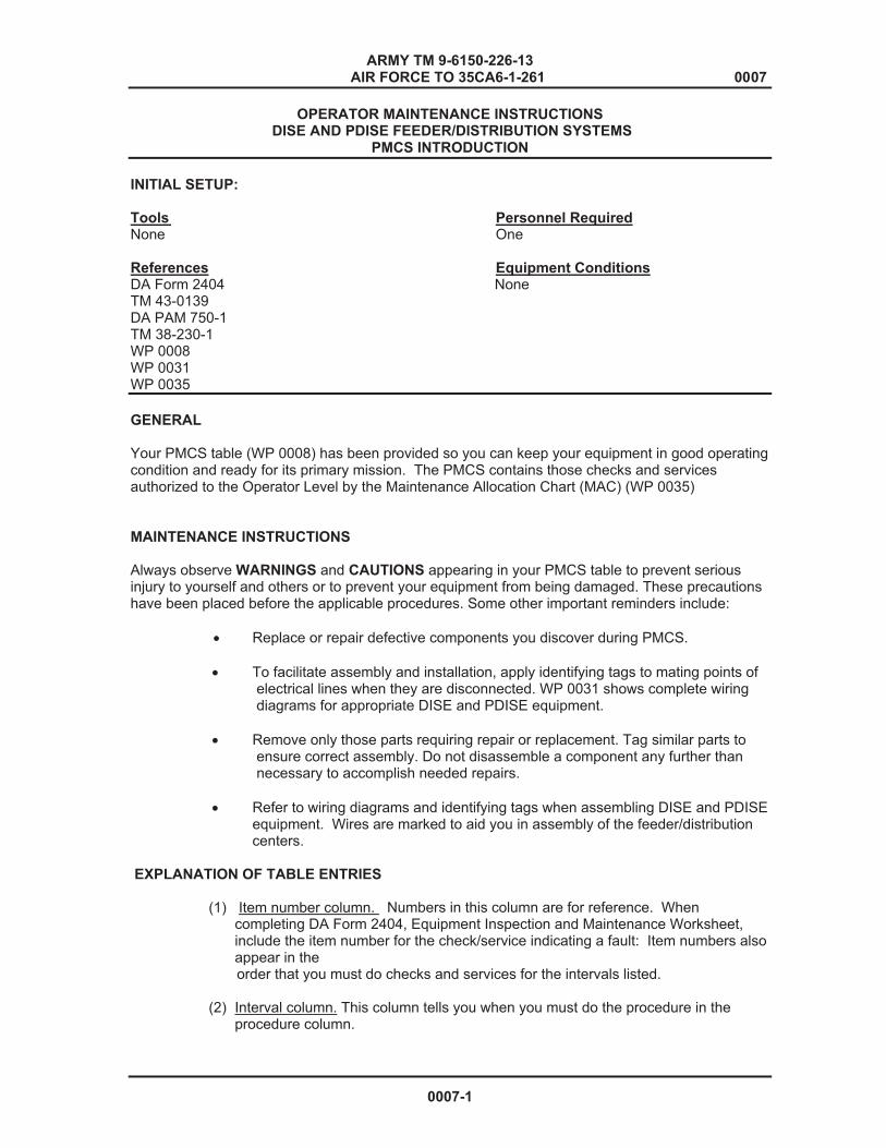
ARMY TM 9-6150-226-13 AIR FORCE TO 35CA6-1-261 0007
OPERATOR MAINTENANCE INSTRUCTIONS DISE AND PDISE FEEDER/DISTRIBUTION SYSTEMS
PMCS INTRODUCTION
INITIAL SETUP:
Tools Personnel RequiredNone One References Equipment Conditions DA Form 2404 None TM 43-0139 DA PAM 750-1 TM 38-230-1 WP 0008 WP 0031 WP 0035
GENERAL
Your PMCS table (WP 0008) has been provided so you can keep your equipment in good operating condition and ready for its primary mission. The PMCS contains those checks and services authorized to the Operator Level by the Maintenance Allocation Chart (MAC) (WP 0035)
MAINTENANCE INSTRUCTIONS Always observe WARNINGS and CAUTIONS appearing in your PMCS table to prevent serious injury to yourself and others or to prevent your equipment from being damaged. These precautions have been placed before the applicable procedures. Some other important reminders include:
� Replace or repair defective components you discover during PMCS.
� To facilitate assembly and installation, apply identifying tags to mating points of electrical lines when they are disconnected. WP 0031 shows complete wiring diagrams for appropriate DISE and PDISE equipment.
� Remove only those parts requiring repair or replacement. Tag similar parts to
ensure correct assembly. Do not disassemble a component any further than necessary to accomplish needed repairs.
� Refer to wiring diagrams and identifying tags when assembling DISE and PDISE
equipment. Wires are marked to aid you in assembly of the feeder/distribution centers.
EXPLANATION OF TABLE ENTRIES
(1) Item number column. Numbers in this column are for reference. When completing DA Form 2404, Equipment Inspection and Maintenance Worksheet, include the item number for the check/service indicating a fault: Item numbers also appear in the
order that you must do checks and services for the intervals listed.
(2) Interval column. This column tells you when you must do the procedure in the procedure column.
0007-1
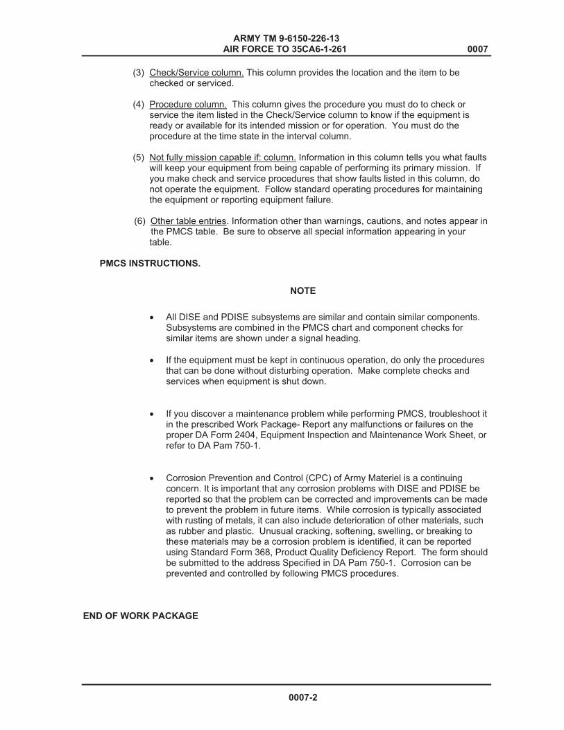
ARMY TM 9-6150-226-13 AIR FORCE TO 35CA6-1-261 0007
(3) Check/Service column. This column provides the location and the item to be checked or serviced.
(4) Procedure column. This column gives the procedure you must do to check or
service the item listed in the Check/Service column to know if the equipment is ready or available for its intended mission or for operation. You must do the procedure at the time state in the interval column.
(5) Not fully mission capable if: column. Information in this column tells you what faults
will keep your equipment from being capable of performing its primary mission. If you make check and service procedures that show faults listed in this column, do not operate the equipment. Follow standard operating procedures for maintaining the equipment or reporting equipment failure.
(6) Other table entries. Information other than warnings, cautions, and notes appear in the PMCS table. Be sure to observe all special information appearing in your table. PMCS INSTRUCTIONS.
� All DISE and PDISE subsystems are similar and contain similar components. Subsystems are combined in the PMCS chart and component checks for similar items are shown under a signal heading.
� If the equipment must be kept in continuous operation, do only the procedures
that can be done without disturbing operation. Make complete checks and services when equipment is shut down.
� If you discover a maintenance problem while performing PMCS, troubleshoot it in the prescribed Work Package- Report any malfunctions or failures on the proper DA Form 2404, Equipment Inspection and Maintenance Work Sheet, or refer to DA Pam 750-1.
� Corrosion Prevention and Control (CPC) of Army Materiel is a continuing concern. It is important that any corrosion problems with DISE and PDISE be reported so that the problem can be corrected and improvements can be made to prevent the problem in future items. While corrosion is typically associated with rusting of metals, it can also include deterioration of other materials, such as rubber and plastic. Unusual cracking, softening, swelling, or breaking to these materials may be a corrosion problem is identified, it can be reported using Standard Form 368, Product Quality Deficiency Report. The form should be submitted to the address Specified in DA Pam 750-1. Corrosion can be prevented and controlled by following PMCS procedures.
END OF WORK PACKAGE
0007-2
NOTE

TM 9-6150-226-13 0008
OPERATOR MAINTENANCE INSTRUCTIONS DISE AND PDISE SYSTEMS
PREVENTIVE MAINTENANCE CHECKS AND SERVICES (PMCS)
INITIAL SETUP:
Tools and Special Tools Personnel RequiredNone One
Materials and Parts ReferencesNone WP 0001 WP 0003 WP 0007 WP 0036 Equipment Conditions System is Shut Down
Table 1. Operator Preventive Maintenance Checks and Services.Item Interval Location Item
toCheck/Service
Procedure Not fully MissionCapable if:
1 2 3
Before
Before
Before
Electrical Feeder System M200, 200(AP) M100, 100 (AP) Circuit breaker Connectors on feeder system
WARNINGHigh voltage is present in this equipment. DISE/PDISE supports equipment using 120/208 VAC. Do not perform PMCS with the power on. Death or serious injury may result. a. Check that unused connectors are capped and center lid is closed. a. Check for damaged circuit breakers. a. Check for damaged connectors. Ensure that all pins and connector lugs are serviceable.
Circuit breakers are damaged so as to affect the function or safety. Notify next level maintenance. Connectors are damaged, burnt, broken or missing. Notify next level maintenance.
0008-1
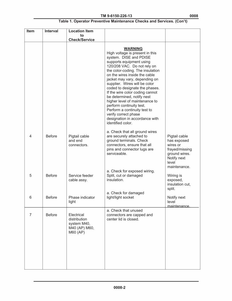
TM 9-6150-226-13 0008Table 1. Operator Preventive Maintenance Checks and Services. (Con’t)
Item Interval Location Item to Check/Service
4 5 6 7
Before
Before
Before
Before
Pigtail cable and end connectors. Service feeder cable assy. Phase indicator light Electrical distribution system M40, M40 (AP) M60, M60 (AP)
WARNING
High voltage is present in this system. DISE and PDISE supports equipment using 120/208 VAC. Do not rely on the color-coding. The insulation on the wires inside the cable jacket may vary, depending on supplier. Wires will be color coded to designate the phases. If the wire color coding cannot be determined, notify nest higher level of maintenance to perform continuity test. Perform a continuity test to verify correct phase designation in accordance with identified color. a. Check that all ground wires are securely attached to ground terminals. Check connectors, ensure that all pins and connector lugs are serviceable. a. Check for exposed wiring. Split, cut or damaged insulation. a. Check for damaged light/light socket a. Check that unused connectors are capped and center lid is closed.
Pigtail cable has exposed wires or frayed/missing ground wires. Notify next level maintenance. Wiring is exposed, insulation cut, split. Notify next level maintenance.
0008-2
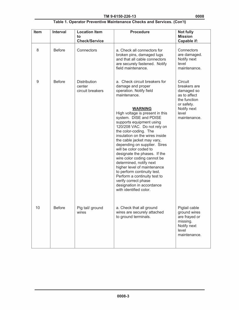
TM 9-6150-226-13 0008Table 1. Operator Preventive Maintenance Checks and Services. (Con’t)
Item Interval Location Item toCheck/Service
Procedure Not fully MissionCapable if:
8 9
10
Before
Before
Before
Connectors Distribution center circuit breakers Pig tail/ ground wires
a. Check all connectors for broken pins, damaged lugs and that all cable connectors are securely fastened. Notify field maintenance. a. Check circuit breakers for damage and proper operation. Notify field maintenance. WARNINGHigh voltage is present in this system. DISE and PDISE supports equipment using 120/208 VAC. Do not rely on the color-coding. The insulation on the wires inside the cable jacket may vary, depending on supplier. Sires will be color coded to designate the phases. If the wire color coding cannot be determined, notify next higher level of maintenance to perform continuity test. Perform a continuity test to verify correct phase designation in accordance with identified color. a. Check that all ground wires are securely attached to ground terminals.
Connectors are damaged. Notify next level maintenance. Circuit breakers are damaged so as to affect the function or safety. Notify next level maintenance. Pigtail cable ground wires are frayed or missing. Notify next level maintenance.
0008-3

TM 9-6150-226-13 0008
Table 1. Operator Preventive Maintenance Checks and Services. (Con’t)
Item Interval Location Item to Check/Service
Procedure Not fully MissionCapable if:
11
12
13
14
15
16
17
Before
Before
Before
Before
Before
Before
Before
Extension Cable Assy. Electrical Utility Kit M46 Receptacle groups duplex-boxes Cable assembly, Branch circuit (24ft) Extension Cable Assembly (15 or 25ft) Utility Light Assembly/Fluorescent and/or Incandescent Light
Universal Adapter
a. Check for damaged cable connectors. a. Perform inventory of all items according to Component of End Item List. (WP 0036) a. Check for damaged receptacle groups and connectors. a. Check for damaged cable connectors and split, cut insulation. Check for frayed or exposed wires. Ensure truck assembly is still attached. a. Check for damaged cable connectors and split, cut insulation. Check for frayed or exposed wires. a. Check for frayed or exposed wires. Cable is damaged. Broken bulbs. a. Check for damaged enclosure assembly.
Any faults found, notify next level maintenance.
Missing items.
Cable connectors are damaged or bare wires are exposed. Notify next level maintenance. Cable connectors are damaged or bare wires are exposed. Notify next level maintenance. Bulbs are broken. Enclosure is damaged so that internal wiring is exposed or it will not close.
0008-4
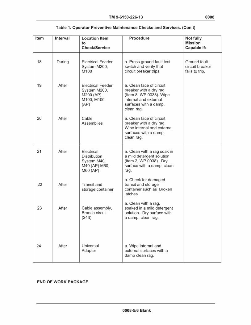
TM 9-6150-226-13 0008
Table 1. Operator Preventive Maintenance Checks and Services. (Con’t)
Item
18
19
20
21
22
23
24
Interval
During
After
After
After
After
After
After
Location Item toCheck/Service
Electrical Feeder System M200, M100 Electrical Feeder System M200, M200 (AP) M100, M100 (AP) Cable Assemblies Electrical Distribution System M40, M40 (AP) M60, M60 (AP) Transit and storage container Cable assembly, Branch circuit (24ft)
Universal Adapter
Procedure
a. Press ground fault test switch and verify that circuit breaker trips. a. Clean face of circuit breaker with a dry rag (Item 8, WP 0038). Wipe internal and external surfaces with a damp, clean rag. a. Clean face of circuit breaker with a dry rag. Wipe internal and external surfaces with a damp, clean rag. a. Clean with a rag soak in a mild detergent solution (item 2, WP 0038). Dry surface with a damp, clean rag. a. Check for damaged transit and storage container such as Broken latches
a. Clean with a rag, soaked in a mild detergent solution. Dry surface with a damp, clean rag.
a. Wipe internal and external surfaces with a damp clean rag.
Not fully MissionCapable if:
Ground fault circuit breaker fails to trip.
END OF WORK PACKAGE
0008-5/6 Blank


Chapter 5
FIELD LEVEL TROUBLESHOOTING


TM 9-6150-226-13 0009
FIELD LEVEL TROUBLESHOOTING PROCEDURES
DISE AND PDISE EQUIPMENT TROUBLESHOOTING INTRODUCTION
INTRODUCTION
This section contains troubleshooting information and test for maintenance personnel to locate and correct malfunctions for DISE/PDISE models. These malfunctions may be observed during PMCS and/or during normal operations of the system or maintenance. The troubleshooting table below lists malfunctions which are authorized by the Maintenance allocation Chart (MAC) followed by a list of probable causes and corrective action.
Troubleshooting consists of isolating the system in which a malfunction occurs and the process of locating the defective component using testing devices and tools identified in the Maintenance Allocation Chart.
The table below lists the common malfunctions which you may find during the operation or maintenance of DISE/PDISE or its components. You should perform the tests/ inspections and corrective actions in the order listed. The manual cannot list all malfunctions that may occur, nor all tests or inspections and corrective actions. If a malfunction is not listed or is not corrected by listed corrective actions, notify next higher level of maintenance. For wiring diagrams (See WP 0031), be sure as to identify which system/model of DISE/PDISE you are troubleshooting.
COMPONENT REFERENCE DESIGNATORS
* Electrical phases are designated with one of two designations as follows:
1. Phase A or L1 2. Phase B or L2 3. Phase C or L3 4. Neutral (N) or L0
* DISE and PDISE feeder/distribution center wires are designated with the following examples:
1. Example 1- J2A4L1 is broken down as follows:
a. J2A = wire originates from connector J2, pin A. b. 4-wire = #4 gauge. c. L1 = wire connects to phase bus L1 (phase A).
2. Example 2- J8B12NEUT.
a. J8B = wire originates from connector J8, pin B. b. 12 = wire is #12 gauge. c. NEUT = wire connects to neutral phase bus (L0). 3. Example 3- J14A12CB14. a. J14A = wire originates from connector J14, pin A. b. 1 = wire is #12 gauge. c. CB14 = wire connects to circuit breaker #14.
0009-1
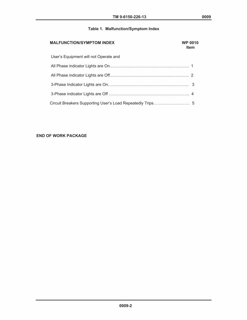
TM 9-6150-226-13 0009
Table 1. Malfunction/Symptom Index
MALFUNCTION/SYMPTOM INDEX WP 0010 Item User’s Equipment will not Operate and All Phase indicator Lights are On………………………………………………….. 1 All Phase indicator Lights are Off………………………………………………….. 2 3-Phase Indicator Lights are On…………………………………………………… 3 3-Phase indicator Lights are Off …………………………………………………... 4 Circuit Breakers Supporting User’s Load Repeatedly Trips……………………… 5 END OF WORK PACKAGE
0009-2
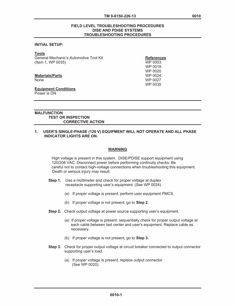
TM 9-6150-226-13 0010
FIELD LEVEL TROUBLESHOOTING PROCEDURES DISE AND PDISE SYSTEMS
TROUBLESHOOTING PROCEDURES
INITIAL SETUP:
ToolsGeneral Mechanic’s Automotive Tool Kit References (Item 1, WP 0035) WP 0003 WP 0018 WP 0020 Materials/Parts WP 0024 None WP 0027 WP 0035 Equipment Conditions Power is ON
MALFUNCTION TEST OR INSPECTION CORRECTIVE ACTION
1. USER’S SINGLE-PHASE (120 V) EQUIPMENT WILL NOT OPERATE AND ALL PHASE INDICATOR LIGHTS ARE ON.
WARNING
High voltage is present in this system. DISE/PDISE support equipment using 120/208 VAC. Disconnect power before performing continuity checks. Be careful not to contact high-voltage connections when troubleshooting this equipment. Death or serious injury may result.
Step 1. Use a multimeter and check for proper voltage at duplex receptacle supporting user’s equipment. (See WP 0024) (a) If proper voltage is present, perform user equipment PMCS. (b) If proper voltage is not present, go to Step 2. Step 2. Check output voltage at power source supporting user’s equipment. (a) If proper voltage is present, sequentially check for proper output voltage at each cable between last center and user’s equipment. Replace cable as necessary. (b) If proper voltage is not present, go to Step 3. Step 3. Check for proper output voltage at circuit breaker connected to output connector supporting user’s load. (a) If proper voltage is present, replace output connector (See WP 0020).
0010-1
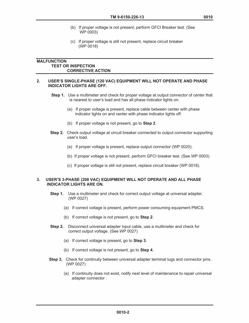
TM 9-6150-226-13 0010 (b) If proper voltage is not present, perform GFCI Breaker test. (See WP 0003)
(c) If proper voltage is still not present, replace circuit breaker (WP 0018)
MALFUNCTION TEST OR INSPECTION CORRECTIVE ACTION
2. USER’S SINGLE-PHASE (120 VAC) EQUIPMENT WILL NOT OPERATE AND PHASE INDICATOR LIGHTS ARE OFF. Step 1. Use a multimeter and check for proper voltage at output connector of center that is nearest to user’s load and has all phase indicator lights on.
(a) If proper voltage is present, replace cable between center with phase indicator lights on and center with phase indicator lights off. (b) If proper voltage is not present, go to Step 2. Step 2. Check output voltage at circuit breaker connected to output connector supporting user’s load. (a) If proper voltage is present, replace output connector (WP 0020).
(b) If proper voltage is not present, perform GFCI breaker test. (See WP 0003) (c) If proper voltage is still not present, replace circuit breaker (WP 0018).
3. USER’S 3-PHASE (208 VAC) EQUIPMENT WILL NOT OPERATE AND ALL PHASE INDICATOR LIGHTS ARE ON.
Step 1. Use a multimeter and check for correct output voltage at universal adapter. (WP 0027) (a) If correct voltage is present, perform power consuming equipment PMCS. (b) If correct voltage is not present, go to Step 2. Step 2. Disconnect universal adapter input cable, use a multimeter and check for correct output voltage. (See WP 0027) (a) If correct voltage is present, go to Step 3. (b) If correct voltage is not present, go to Step 4. Step 3. Check for continuity between universal adapter terminal lugs and connector pins. (WP 0027) (a) If continuity does not exist, notify next level of maintenance to repair universal adapter connector .
0010-2
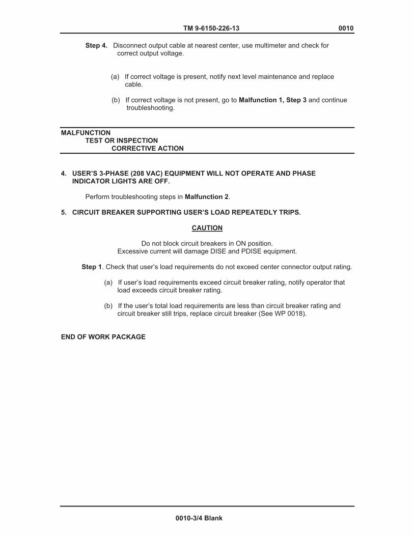
TM 9-6150-226-13 0010
Step 4. Disconnect output cable at nearest center, use multimeter and check for correct output voltage. (a) If correct voltage is present, notify next level maintenance and replace cable. (b) If correct voltage is not present, go to Malfunction 1, Step 3 and continue troubleshooting.
MALFUNCTION TEST OR INSPECTION CORRECTIVE ACTION
4. USER’S 3-PHASE (208 VAC) EQUIPMENT WILL NOT OPERATE AND PHASE INDICATOR LIGHTS ARE OFF.
Perform troubleshooting steps in Malfunction 2. 5. CIRCUIT BREAKER SUPPORTING USER’S LOAD REPEATEDLY TRIPS.
CAUTION
Do not block circuit breakers in ON position. Excessive current will damage DISE and PDISE equipment.
Step 1. Check that user’s load requirements do not exceed center connector output rating. (a) If user’s load requirements exceed circuit breaker rating, notify operator that load exceeds circuit breaker rating. (b) If the user’s total load requirements are less than circuit breaker rating and circuit breaker still trips, replace circuit breaker (See WP 0018). END OF WORK PACKAGE
0010-3/4 Blank


Chapter 6
FIELD LEVEL MAINTENANCE


TM 9-6150-226-13 0011
FIELD LEVEL MAINTENANCE INSTRUCTIONS DISE AND PDISE SYSTEMS SERVICE UPON RECEIPT
INITIAL SETUP:
Tools References None SF Form 364 DA PAM 750-1 TM 9-6150-226-24P Materials/Parts None Personnel Required One Equipment Conditions System is Shut Down
INTRODUCTION MOS 52D, Power Generator Equipment Repairer, is authorized to perform all maintenance on DISE/PDISE equipment. CHECKING UNPACKED EQUIPMENT.
a. Inspect the equipment for damage incurred during shipment. If the equipment has been damaged, report the damage on SF Form 364, Report of Discrepancy.
b. Check the equipment against the packing list to see if the shipment is complete.
. c. Report all discrepancies in accordance with the instructions of DA PAM 750-1.
d. Check current publications to determine if equipment has been modified or is
projected to be modified.
0011-1
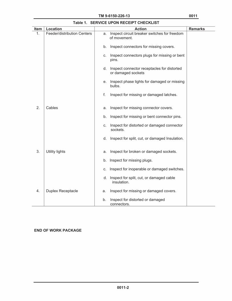
TM 9-6150-226-13 0011
Table 1. SERVICE UPON RECEIPT CHECKLIST
END OF WORK PACKAGE
Item Location Action Remarks 1.
2.
3.
4.
Feeder/distribution Centers Cables Utility lights Duplex Receptacle
a. Inspect circuit breaker switches for freedom of movement.
b. Inspect connectors for missing covers.
c. Inspect connectors plugs for missing or bent pins.
d. Inspect connector receptacles for distorted or damaged sockets
e. Inspect phase lights for damaged or missing bulbs.
f. Inspect for missing or damaged latches.
a. Inspect for missing connector covers.
b. Inspect for missing or bent connector pins.
c. Inspect for distorted or damaged connector sockets.
d. Inspect for split, cut, or damaged Insulation.
a. Inspect for broken or damaged sockets.
b. Inspect for missing plugs.
c. Inspect for inoperable or damaged switches. d. Inspect for split, cut, or damaged cable
insulation.
a. Inspect for missing or damaged covers. b. Inspect for distorted or damaged connectors.
0011-2
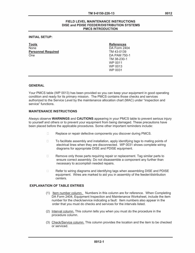
TM 9-6150-226-13 0012
FIELD LEVEL MAINTENANCE INSTRUCTIONS DISE and PDISE FEEDER/DISTRIBUTION SYSTEMS
PMCS INTRODUCTION
INITIAL SETUP: Tools ReferencesNone DA Form 2404 Personnel Required TM 43-0139 One DA PAM 750-1 TM 38-230-1 WP 0011 WP 0013 WP 0031
GENERAL
Your PMCS table (WP 0013) has been provided so you can keep your equipment in good operating condition and ready for its primary mission. The PMCS contains those checks and services authorized to the Service Level by the maintenance allocation chart (MAC) under “inspection and service” functions. MAINTENANCE INSTRUCTIONS Always observe WARNINGS and CAUTIONS appearing in your PMCS table to prevent serious injury to yourself and others or to prevent your equipment from being damaged. These precautions have been placed before the applicable procedures. Some other important reminders include:
� Replace or repair defective components you discover during PMCS.
� To facilitate assembly and installation, apply identifying tags to mating points of electrical lines when they are disconnected. WP 0031 shows complete wiring diagrams for appropriate DISE and PDISE equipment.
� Remove only those parts requiring repair or replacement. Tag similar parts to
ensure correct assembly. Do not disassemble a component any further than necessary to accomplish needed repairs.
� Refer to wiring diagrams and identifying tags when assembling DISE and PDISE
equipment. Wires are marked to aid you in assembly of the feeder/distribution centers.
EXPLANATION OF TABLE ENTRIES
(1) Item number column. Numbers in this column are for reference. When Completing DA Form 2404, Equipment Inspection and Maintenance Worksheet, include the item number for the check/service indicating a fault: Item numbers also appear in the
order that you must do checks and services for the intervals listed.
(2) Interval column. This column tells you when you must do the procedure in the procedure column.
(3) Check/Service column. This column provides the location and the item to be checked
or serviced.
0012-1

TM 9-6150-226-13 0012
(4) Procedure column. This column gives the procedure you must do to check or service the item listed in the Check/Service column to know if the equipment is ready or available for its intended mission or for operation. You must do the procedure at the time state in the interval column.
(5) Not fully mission capable if: column. Information in this column tells you what faults
will keep your equipment from being capable of performing its primary mission. If you make check and service procedures that show faults listed in this column, do not operate the equipment. Follow standard operating procedures for maintaining the equipment or reporting equipment failure.
(6) Other table entries . Information other than warnings, cautions, and notes appear in
the PMCS table. Be sure to observe all special information appearing in your table. PMCS INSTRUCTIONS.
NOTES
� All DISE and PDISE subsystems are similar and contain similar components. Subsystems are combined in the PMCS chart and component checks for similar items are shown under a signal heading.
� If the equipment must be kept in continuous operation, do only the procedures
that can be done without disturbing operation. Make complete checks and services when equipment is shut down.
� If you discover a maintenance problem while performing PMCS, troubleshoot malfunctions contained in WP 0011. Report any malfunctions or failures on the proper DA Form 2404, Equipment Inspection and Maintenance Work Sheet, or refer to DA Pam 750-1.
� Corrosion Prevention and Control (CPC) of Army Materiel is a continuing concern. It is important that any corrosion problems with DISE and PDISE be reported so that the problem can be corrected and improvements can be made to prevent the problem in future items. While corrosion is typically associated with rusting of metals, it can also include deterioration of other materials, such as rubber and plastic. Unusual cracking, softening, swelling, or breaking to these materials may be a corrosion problem is identified, it can be reported using Standard Form 368, Product Quality Deficiency Report. The form should be submitted to the address Specified in DA Pam 750-1. Corrosion can be prevented and controlled by following PMCS procedures.
PAINTING.
a. Remove rust, corrosion, and flaked and peeling paint. Ensure surfaces to be painted are dry. Refer to TM 38-230-1, Packaging of Materiel: Preservation.
b. Use masking tape (item 10, App E) and mask connectors and data plates that are not to
be painted.
c. Use paint (item 7, App E) and paint surfaces as required to protect against deterioration. Refer to TM 43-0139, Painting Instructions for Army Materiel.
END OF WORK PACKAGE
0012-2
TM 9-6150-226-13 0013
FIELD LEVEL MAINTENANCE INSTRUCTIONS DISE and PDISE EQUIPMENT
PREVENTIVE MAINTENANCE CHECKS AND SERVICES (PMCS)
INITIAL SETUP: Tools Personnel Required General Mechanic’s Automotive Tool Kit One (Item 1, WP 0035) ReferencesEquipment Conditions DA Form 2404 System shut down DA PAM 750-1 WP 0003 WP 0040
NOTE
If the equipment must be kept in continuous operation, check and service only those items that can be checked and serviced without disturbing operation. Make the complete checks and services when the equipment can be shut down.
WARNING
High voltage is present in this equipment. DISE/PDISE support equipment using 120/208 VAC. Do not perform PMCS with the power on. Failure to adhere to warning may cause death or serious injury may result.
0013-1
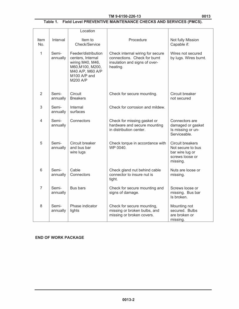
TM 9-6150-226-13 0013 Table 1. Field Level PREVENTIVE MAINTENANCE CHECKS AND SERVICES (PMCS).
Item No.
Interval
Location
Item to Check/Service
Procedure
Not fully Mission Capable if:
1
2
3
Semi- annually Semi- annually Semi-annually
Feeder/distribution centers, Internal wiring M40, M46, M60,M100, M200, M40 A/P, M60 A/P M100 A/P and M200 A/P Circuit Breakers Internal surfaces
Check internal wiring for secure connections. Check for burnt insulation and signs of over- heating. Check for secure mounting. Check for corrosion and mildew.
Wires not secured by lugs. Wires burnt. Circuit breaker not secured
4
5
6
7
8
Semi- annually Semi- annually Semi- annually Semi- annually Semi- annually
Connectors Circuit breaker and bus bar wire lugs Cable Connectors Bus bars Phase indicator lights
Check for missing gasket or hardware and secure mounting in distribution center. Check torque in accordance with WP 0040. Check gland nut behind cable connector to insure nut is tight. Check for secure mounting and signs of damage. Check for secure mounting, missing or broken bulbs, and missing or broken covers.
Connectors are damaged or gasket Is missing or un- Serviceable. Circuit breakers Not secure to bus bar wire lug or screws loose or missing. Nuts are loose or missing. Screws loose or missing. Bus bar Is broken. Mounting not secured. Bulbs are broken or missing.
END OF WORK PACKAGE
0013-2

TM 9-6150-226-13 0014
FIELD LEVEL MAINTENANCE INSTRUCTIONS DISE AND PDISE SYSTEM
PREPARATION FOR STORAGE
INITIAL SETUP: References Tools TM 38-230-2 General Mechanic’s Automotive Tool Kit SB 740-99-9 (Item 1, WP 0035) TM 38-230-1 TM 43- 0139 Equipment Conditions WP 0008 None WP 0034 WP 0038 Materials/Parts Masking Tape (Item 10, WP 0038) Paint, CARC (Item 7, WP 0038)
SCOPE.
a. Instructions in this section apply to the DISE and PDISE equipment to prepare it for storage or shipment.
b. Placement of equipment in administrative storage should be for short periods of time
when a shortage of maintenance effort exists. Items should be in mission readiness within 24 hours or within the item factors as developed by the directing authority. During the storage period appropriate maintenance records should be kept.
c. Before placing equipment in administrative storage, current maintenance services and Equipment Serviceable Criteria (ESC) evaluations should be completed. Shortcomings and deficiencies should be corrected, and all Modification Work Orders (MWOs) should be applied.
d. Storage site selection. Inside is preferred for items selected for administrative storage. If
inside storage is not available, trucks, vans, conex containers and other containers may be used.
PREPARATION FOR STORAGE OR SHIPMENT.
a. Inspection. Perform preventive maintenance checks and services Iisted in applicable work package.
b. Repair. Correct deficiencies noted during the inspection. Refer repairs beyond the scope of user/maintenance personnel to applicable maintenance level personnel.
c. Cleaning. Refer to operator PMCS (WP 0008) for cleaning instructions.
d. Painting.
(1) Remove rust, corrosion, and flaked and peeling paint. Ensure surfaces to be painted
are dry. Refer to TM 38-230-1, Packaging of Material: Preservation.
(2) Mask connectors and data plates that are not to be painted with masking tape.
(3) Paint surface, as required, to protect against deterioration. Refer to TM 43- 0139, Painting Instructions for Army Materiel.
0014-1

TM 9-6150-226-13 0014 e. Packaginq. Refer to TM 38-230-2, Packing.
END OF WORK PACKAGE
0014-2

TM 9-6150-226-13 0015
FIELD LEVEL MAINTENANCE INSTRUCTIONS LANYARD ASSEMBLY
REPLACE
INITIAL SETUP: Tools References General Mechanic’s Automotive Tool Kit (Item 1, WP 0035) Equipment Conditions Power shut down .
REPLACE
CAUTION Failure to support the lid after lanyards are removed may result in damage to the hinges. 1. Remove screws (1), nuts (2), washers (3), and lanyards (4) from box and lid. 2. Install lanyard assembly (4) on box and lid and secure with washers (3), nuts (2), and screws (1).
Figure 1. Lanyard Assembly END OF WORK PACKAGE
0015-1/ 2 Blank

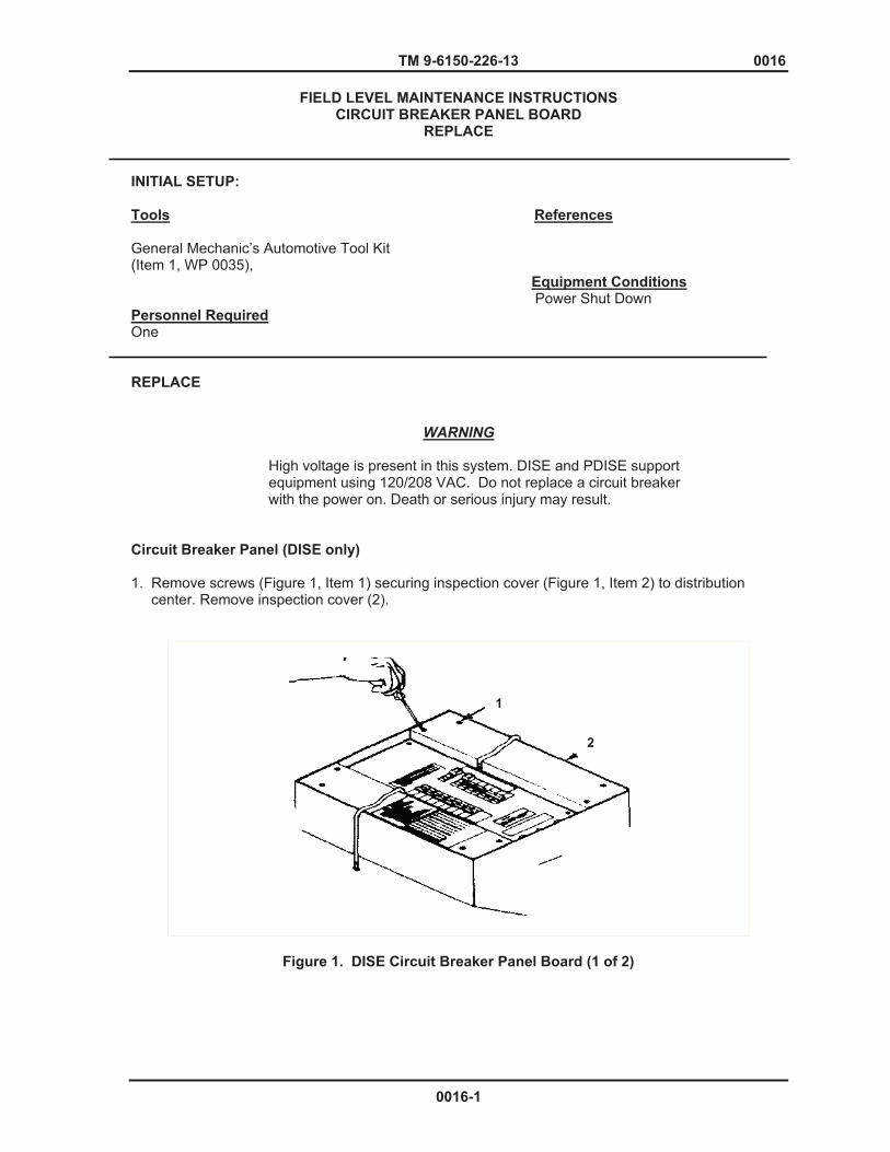
TM 9-6150-226-13 0016
FIELD LEVEL MAINTENANCE INSTRUCTIONS CIRCUIT BREAKER PANEL BOARD
REPLACE
INITIAL SETUP: Tools References General Mechanic’s Automotive Tool Kit (Item 1, WP 0035), Equipment Conditions Power Shut Down Personnel Required One REPLACE
WARNING High voltage is present in this system. DISE and PDISE support equipment using 120/208 VAC. Do not replace a circuit breaker with the power on. Death or serious injury may result.
Circuit Breaker Panel (DISE only)
1. Remove screws (Figure 1, Item 1) securing inspection cover (Figure 1, Item 2) to distribution center. Remove inspection cover (2).
Figure 1. DISE Circuit Breaker Panel Board (1 of 2)
1
2
0016-1

TM 9-6150-226-13 0016
2. Remove screws (Figure 1, Item 3) securing panel to bus bar assembly.
3. Tag and disconnect phase indicator lights (Figure 1, Item 4) from circuit breaker and neutral bus bar. 4. Remove circuit breaker panel (Figure 1, Item 5).
Figure 1. DISE Circuit Breaker Panel Board (2 of 2)
Circuit Breaker Panel (PDISE only)
1. Remove screws (Figure 2, Item 2) securing panel cover (Figure 2, Item 1) to distribution center.
Figure 2. PDISE Circuit Breaker Panel Board
2. Install panel cover (1) and secure with screws (2).
END OF WORK PACKAGE
3
4
5
12
0016-2
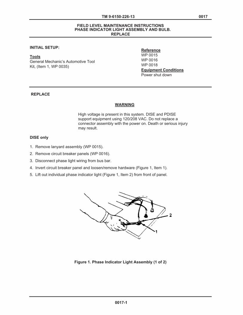
TM 9-6150-226-13 0017
FIELD LEVEL MAINTENANCE INSTRUCTIONS PHASE INDICATOR LIGHT ASSEMBLY AND BULB.
REPLACE
INITIAL SETUP:
Tools General Mechanic’s Automotive Tool Kit, (Item 1, WP 0035)
Reference WP 0015 WP 0016 WP 0018 Equipment Conditions Power shut down
REPLACE
High voltage is present in this system. DISE and PDISE support equipment using 120/208 VAC. Do not replace a connector assembly with the power on. Death or serious injury may result.
DISE only 1. Remove lanyard assembly (WP 0015).
2. Remove circuit breaker panels (WP 0016).
3. Disconnect phase light wiring from bus bar.
4. Invert circuit breaker panel and loosen/remove hardware (Figure 1, Item 1).
5. Lift out individual phase indicator light (Figure 1, Item 2) from front of panel.
Figure 1. Phase Indicator Light Assembly (1 of 2)
WARNING
0017-1

TM 9-6150-226-13 0017
6. Insert phase indicator light (2) through front of panel.
7. Install and tighten hardware (1) on phase indicator light.
8. Connect phase light wiring to bus bar.
9. Install circuit breaker cover panels (WP 0016).
10. Install lanyard assembly (WP 0015).
PDISE only 1. Remove lanyard assembly (WP 0015).
2. Remove circuit breaker panels (WP 0016).
3. Remove circuit breaker assembly (WP 0018).
4. Disconnect phase light wiring assembly from bus bars.
5. Remove screws (Figure 1, Item 3), nuts (Figure 1, Item 4), and washers (Figure 1, Item 5) from light bracket mounting (Figure 1, Item 6). 6. Remove nut (7) and washer (8) from phase indicator light (9).
7. Lift out phase indicator light (9) from light bracket mounting (6).
Figure 1. Phase Indicator Light Assembly (2 of 2)
0017-2
TM 9-6150-226-13 0017 8. Insert phase indicator light (9) through top of light bracket mounting (6).
9. Install washer (8) and tighten nut (7).
10. Install washers (5) and tighten nuts (4).
11. Install screws (3) in light bracket mounting (6) and tighten.
12. Connect phase light wire to bus bar.
13. Install circuit breaker assembly (WP 0018).
14. Install circuit breaker cover panels (WP 0016).
15. Install lanyard assembly (WP 0015).
BULB REPLACEMENT
Unscrew colored lens and replace bulb.
END OF WORK PACKAGE
0017-3/4 Blank

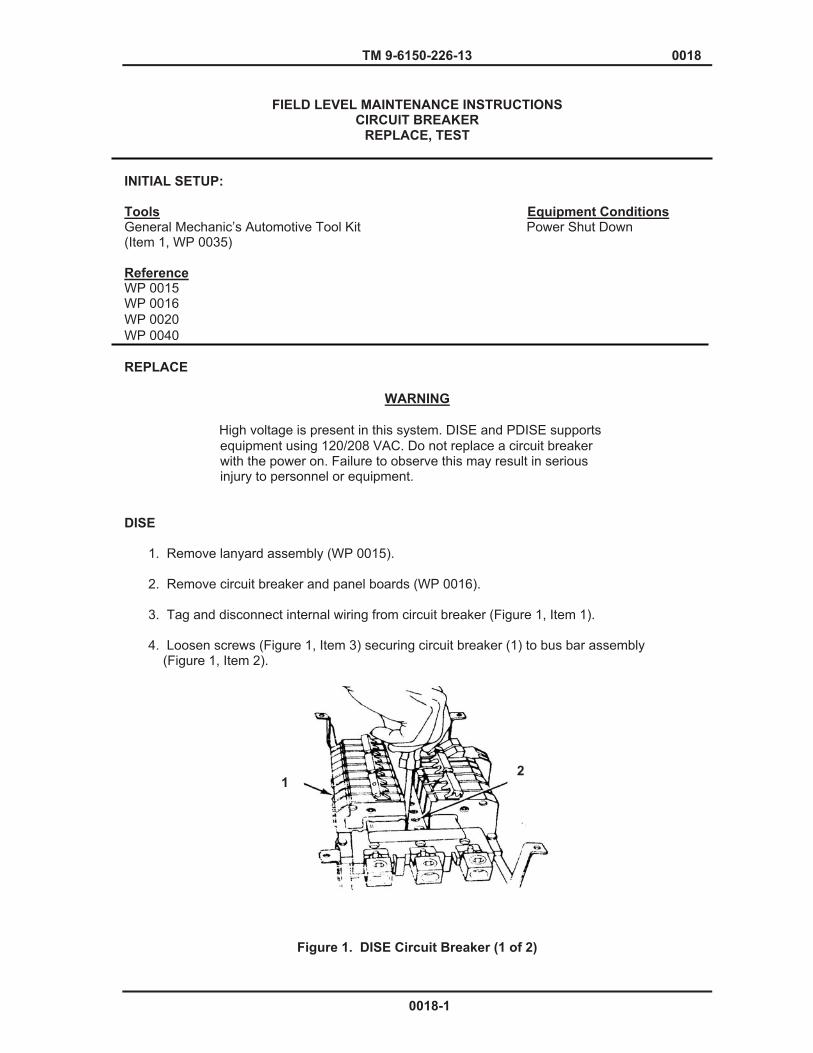
TM 9-6150-226-13 0018
FIELD LEVEL MAINTENANCE INSTRUCTIONS CIRCUIT BREAKER
REPLACE, TEST INITIAL SETUP: Tools Equipment Conditions General Mechanic’s Automotive Tool Kit Power Shut Down (Item 1, WP 0035) Reference WP 0015 WP 0016 WP 0020 WP 0040 REPLACE
WARNING
High voltage is present in this system. DISE and PDISE supports equipment using 120/208 VAC. Do not replace a circuit breaker with the power on. Failure to observe this may result in serious injury to personnel or equipment.
DISE
1. Remove lanyard assembly (WP 0015). 2. Remove circuit breaker and panel boards (WP 0016). 3. Tag and disconnect internal wiring from circuit breaker (Figure 1, Item 1). 4. Loosen screws (Figure 1, Item 3) securing circuit breaker (1) to bus bar assembly (Figure 1, Item 2).
Figure 1. DISE Circuit Breaker (1 of 2)
1 2
0018-1

TM 9-6150-226-13 0018
5. Tilt circuit breaker (1) away from bus bar assembly (2) and remove circuit breaker (1).
Circuit breaker support rails are marked with phase designations. All Breakers must be installed in the correct pole space in order to maintain proper phases.
6. Hook circuit breaker (1) on support rail, swing down into place, and secure with screws (3). 7. Connect internal wiring to circuit breaker (1) and remove tags. 8. Torque circuit breaker lug in accordance with WP 0040 specifications.
Figure 1. DISE Circuit Breaker (2 of 2)
9. Install circuit breaker panel board (WP 0016).
10. Install lanyard assembly (WP 0015).
PDISE
1. Remove lanyard assembly (WP 0015).
2. Remove circuit breaker and panel boards (WP 0016).
3. Tag and disconnect internal wiring (Figure 2, Item 1) from circuit breaker (Figure 2, Item 2). 4. Remove screws (Figure 2, Item 3) securing circuit breakers (2) to support rails. 5. Remove circuit breakers (2) from support rails
1
3
NOTE
0018-2
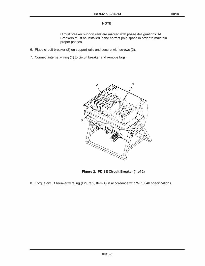
TM 9-6150-226-13 0018
Circuit breaker support rails are marked with phase designations. All Breakers must be installed in the correct pole space in order to maintain proper phases.
6. Place circuit breaker (2) on support rails and secure with screws (3). 7. Connect internal wiring (1) to circuit breaker and remove tags.
Figure 2. PDISE Circuit Breaker (1 of 2)
8. Torque circuit breaker wire lug (Figure 2, Item 4) in accordance with WP 0040 specifications.
12
3
NOTE
0018-3
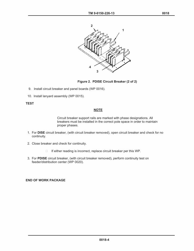
TM 9-6150-226-13 0018
Figure 2. PDISE Circuit Breaker (2 of 2)
9. Install circuit breaker and panel boards (WP 0016).
10. Install lanyard assembly (WP 0015).
TEST
Circuit breaker support rails are marked with phase designations. All breakers must be installed in the correct pole space in order to maintain proper phases.
1. For DISE circuit breaker, (with circuit breaker removed), open circuit breaker and check for no continuity. 2. Close breaker and check for continuity.
� If either reading is incorrect, replace circuit breaker per this WP. 3. For PDISE circuit breaker, (with circuit breaker removed), perform continuity test on feeder/distribution center (WP 0020).
END OF WORK PACKAGE
21
1 4 3
NOTE
0018-4

TM 9-6150-226-13 0019
FIELD LEVEL MAINTENANCE INSTRUCTIONS CIRCUIT BREAKER AND BUS BAR ASSEMBLY
REPLACE, TEST INITIAL SETUP: Tools Equipment Conditions General Mechanic’s Automotive Tool Kit Power Shut Down (Item 1, WP 0035) Reference Materials/Parts WP 0003 Kester Solder (Item 17, WP 0038) WP 0015 WP 0016 WP 0017 WP 0018 WP 0040 REPLACE
WARNING
High voltage is present in this system. DISE and PDISE supports equipment using 120/208 VAC. Do not replace a circuit breaker with the power on. Failure to observe this may result in serious injury to personnel or equipment.
DISE (Circuit Breaker Assembly and Bus Bar Terminal)
CAUTION
Ground fault circuit breaker (DISE only) has the panel neutral wire permanently attached inside the circuit breaker. Disconnect this wire at the bus bar.
1. Remove lanyard assembly (WP 0015). 2. Remove circuit breaker and panel boards (WP 0016). 3. Tag and disconnect wiring from circuit breakers and bus bars. 4. Remove screw (Figure 1, Item 1) securing circuit breaker assembly (Figure 1, Item 2).
Figure 1. DISE Circuit Breaker Assembly
0019-1
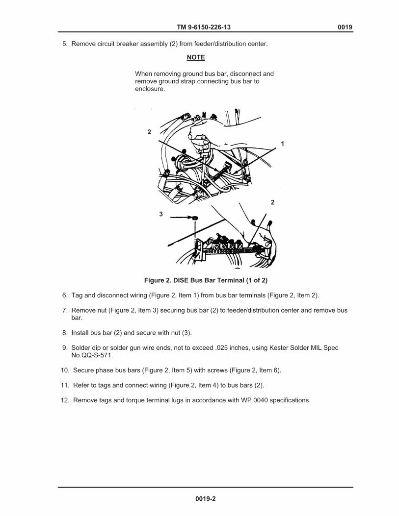
TM 9-6150-226-13 0019
5. Remove circuit breaker assembly (2) from feeder/distribution center.
When removing ground bus bar, disconnect and remove ground strap connecting bus bar to enclosure.
Figure 2. DISE Bus Bar Terminal (1 of 2) 6. Tag and disconnect wiring (Figure 2, Item 1) from bus bar terminals (Figure 2, Item 2). 7. Remove nut (Figure 2, Item 3) securing bus bar (2) to feeder/distribution center and remove bus bar. 8. Install bus bar (2) and secure with nut (3). 9. Solder dip or solder gun wire ends, not to exceed .025 inches, using Kester Solder MIL Spec No.QQ-S-571.
10. Secure phase bus bars (Figure 2, Item 5) with screws (Figure 2, Item 6).
11. Refer to tags and connect wiring (Figure 2, Item 4) to bus bars (2). 12. Remove tags and torque terminal lugs in accordance with WP 0040 specifications.
1
2
2
3
NOTE
0019-2

TM 9-6150-226-13 0019
Figure 2. Bus Bar Terminal (2 of 2)
13. Install circuit breaker assembly (Figure 1, Item 2) and secure with screws (Figure 1, Item 1). 14. Solder dip or solder gun wire ends, not to exceed .025 inches, using MIL SPEC No. QQ-S-571.
15. Refer to tags and connect wiring to circuit breakers. 16. Remove tags and torque in accordance with WP 0039 specifications.
17. Install circuit breakers and panel boards (WP 0018, WP 0016).
18. Install lanyard assembly (WP 0015).
19. Place unit in normal operation (WP 0003).
PDISE (Circuit Breaker Assembly and Bus Bar Terminal)
1. Remove lanyard assembly (WP 0015). 2. Remove circuit breaker and panel boards (WP 0018, WP 0016). 3. Remove phase indicator light assembly (WP 0017)
NOTE
M60 A/P has only Phase A.
4. Tag and disconnect wiring J1-A, B, C (Figure 3, Item 1) from circuit breaker 1 (Figure 3, Item 2).
4
5
6
0019-3

TM 9-6150-226-13 0019
Figure 3. PDISE Circuit Breaker Assembly
5. Remove screws (Figure 3, Item 3) securing circuit breaker assembly (Figure 3, Item 4).
On model M100 A/P, remove circuit breaker 8 for access to mounting screw.
6. Tag and disconnect wiring from circuit breakers {3, 4, 5, 6, 7, 8} (Figure 3, Item 5) and J2-A, B, and C from bus bars L1, L2, and L3. 7. Tilt circuit breaker assembly (4) clockwise for exposure. 8. Tag and disconnect wiring (Figure 2, Item 4) from 3 phase bus bars (Figure 2, Item 5). 9. Remove screws (Figure 2, Item 6) securing bus bars and remove bus bars (5). 10. Tag and disconnect wiring (Figure 4, Item 1) from ground (Figure 4, Item 2) and neutral (Figure 4, Item 3) bus bars.
1
23
4
5
NOTE
0019-4
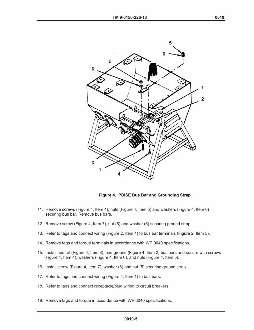
TM 9-6150-226-13 0019
Figure 4. PDISE Bus Bar and Grounding Strap
11. Remove screws (Figure 4, Item 4), nuts (Figure 4, Item 5) and washers (Figure 4, Item 6) securing bus bar. Remove bus bars. 12. Remove screw (Figure 4, Item 7), nut (5) and washer (6) securing ground strap. 13. Refer to tags and connect wiring (Figure 2, Item 4) to bus bar terminals (Figure 2, Item 5). 14. Remove tags and torque terminals in accordance with WP 0040 specifications. 15. Install neutral (Figure 4, Item 3), and ground (Figure 4, Item 2) bus bars and secure with screws (Figure 4, Item 4), washers (Figure 4, Item 6), and nuts (Figure 4, Item 5). 16. Install screw (Figure 4, Item 7), washer (6) and nut (5) securing ground strap. 17. Refer to tags and connect wiring (Figure 4, Item 1) to bus bars. 18. Refer to tags and connect receptacle/plug wiring to circuit breakers. 19. Remove tags and torque in accordance with WP 0040 specifications.
1
2
3
4
5
5 6
6
7
0019-5
TM 9-6150-226-13 0019
Do not secure circuit breaker assembly if performing continuity test.
20. Connect wiring J2-A, B, and C to bus bars. 21. Install circuit breaker assembly (Figure 3, Item 4) and secure with screws (Figure 3, Item 3). 22. Install phase indicator light assembly (WP 0017) 23. Install circuit breaker and panel boards (WP 0018, WP 0016).
24. Install lanyard assembly (WP 0015). 25. Place equipment back into normal operation. (WP 0003)
TEST
WARNING
High voltage is present in this system. DISE and PDISE supports equipment using 120/208 VAC. Do not replace a circuit breaker with the power on. Failure to observe this may result in serious injury to personnel or equipment.
Refer to WP 0020 to perform continuity test on the applicable feeder/distribution center.
Ground Fault Circuit Interrupter (GFCI)
The circuit breakers on the DISE ONLY panel that contain a “PUSH TO TEST” button are of the “GFCI” type. Each GFCI breaker should be tested at the beginning of each setup, at monthly intervals, and following any continuous operation.
1. Connect power source to the input connector. 2. Turn on the main circuit breaker. 3. Turn on the GFCI circuit breaker. 4. Push the “Push to Test Button” and ensure that breaker trips.
� If breaker does not trip, replace GFCI as per this WP.
END OF WORK PACKAGE
NOTE
NOTE
0019-6

TM 9-6150-226-13 0020
FIELD LEVEL MAINTENANCE INSTRUCTIONS FEEDER/DISTRIBUTION CONNECTOR ASSEMBLY
REPLACE, TEST INITIAL SETUP: Tools Equipment Conditions General Mechanic’s Automotive Tool Kit Power shut down (Item 1, WP 0035) Reference Personnel Required WP 0015 One WP 0016 WP 0019 WP 0040
REPLACE The following procedures are only to separate/disconnect the connector “assembly” from the circuit breaker and the enclosure assembly. For repair of Feeder/Distribution connectors, proceed to next level maintenance.
WARNING
High voltage is present in this system. DISE and PDISE support equipment using 120/208 VAC. Do not replace a connector assembly with the power on. Failure to observe warning may result in death or serious injury to personnel.
When disconnecting or connecting wires to bus bar terminal, it is necessary to remove circuit breaker assembly for PDISE.
1. Remove lanyards assembly (WP 0015). 2. Remove circuit breaker panel covers (WP 0016). 3. Remove circuit breaker assembly (WP 0019). 4. Tag and disconnect receptacle/plug wiring from circuit breaker and bus bar terminals. 5. Remove screw (Figure 1, Item 1) securing receptacle/plug and gasket (Figure 1, Item 2) and remove connector, 6. Install receptacle/plug and gasket (2) in mounting hole and secure with screw (1). 7. Connect receptacle/plug wiring and remove tags. 8. Torque terminal lugs in accordance with WP 0040 specifications. 9. Install circuit breaker assembly (WP 0019).
NOTE
0020-1

TM 9-6150-226-13 0020 10. Install circuit breaker panel covers. (WP 0016)
11. Install lanyard assembly (WP 0015).
Figure 1. Feeder/Distribution Connector Assembly
0020-2
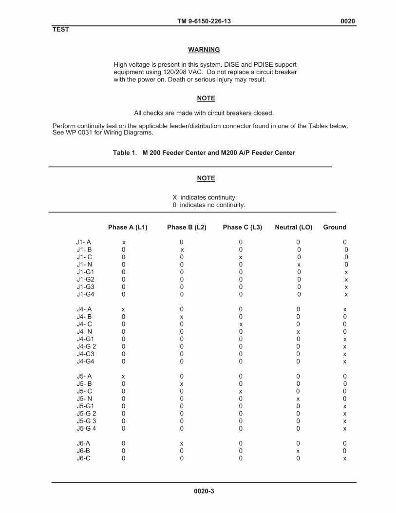
TM 9-6150-226-13 0020 TEST
WARNING High voltage is present in this system. DISE and PDISE support equipment using 120/208 VAC. Do not replace a circuit breaker with the power on. Death or serious injury may result.
All checks are made with circuit breakers closed.
Perform continuity test on the applicable feeder/distribution connector found in one of the Tables below. See WP 0031 for Wiring Diagrams.
Table 1. M 200 Feeder Center and M200 A/P Feeder Center
X indicates continuity. 0 indicates no continuity. Phase A (L1) Phase B (L2) Phase C (L3) Neutral (LO) Ground J1- A x 0 0 0 0
J1- B 0 x 0 0 0 J1- C 0 0 x 0 0 J1- N 0 0 0 x 0 J1-G1 0 0 0 0 x J1-G2 0 0 0 0 x J1-G3 0 0 0 0 x J1-G4 0 0 0 0 x J4- A x 0 0 0 x J4- B 0 x 0 0 0 J4- C 0 0 x 0 0 J4- N 0 0 0 x 0 J4-G1 0 0 0 0 x J4-G 2 0 0 0 0 x J4-G3 0 0 0 0 x J4-G4 0 0 0 0 x J5- A x 0 0 0 0 J5- B 0 x 0 0 0 J5- C 0 0 x 0 0 J5- N 0 0 0 x 0 J5-G1 0 0 0 0 x J5-G 2 0 0 0 0 x J5-G 3 0 0 0 0 x J5-G 4 0 0 0 0 x J6-A 0 x 0 0 0 J6-B 0 0 0 x 0 J6-C 0 0 0 0 x
NOTE
NOTE
0020-3
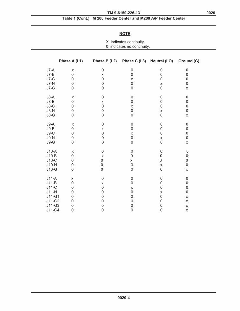
TM 9-6150-226-13 0020 Table 1 (Cont.) M 200 Feeder Center and M200 A/P Feeder Center
X indicates continuity. 0 indicates no continuity.
Phase A (L1) Phase B (L2) Phase C (L3) Neutral (LO) Ground (G)
J7-A x 0 0 0 0 J7-B 0 x 0 0 0 J7-C 0 0 x 0 0 J7-N 0 0 0 x 0 J7-G 0 0 0 0 x J8-A x 0 0 0 0 J8-B 0 x 0 0 0 J8-C 0 0 x 0 0 J8-N 0 0 0 x 0 J8-G 0 0 0 0 x J9-A x 0 0 0 0 J9-B 0 x 0 0 0 J9-C 0 0 x 0 0 J9-N 0 0 0 x 0 J9-G 0 0 0 0 x J10-A x 0 0 0 0 J10-B 0 x 0 0 0 J10-C 0 0 x 0 0 J10-N 0 0 0 x 0 J10-G 0 0 0 0 x J11-A x 0 0 0 0 J11-B 0 x 0 0 0 J11-C 0 0 x 0 0 J11-N 0 0 0 x 0 J11-G1 0 0 0 0 x J11-G2 0 0 0 0 x J11-G3 0 0 0 0 x J11-G4 0 0 0 0 x
NOTE
0020-4
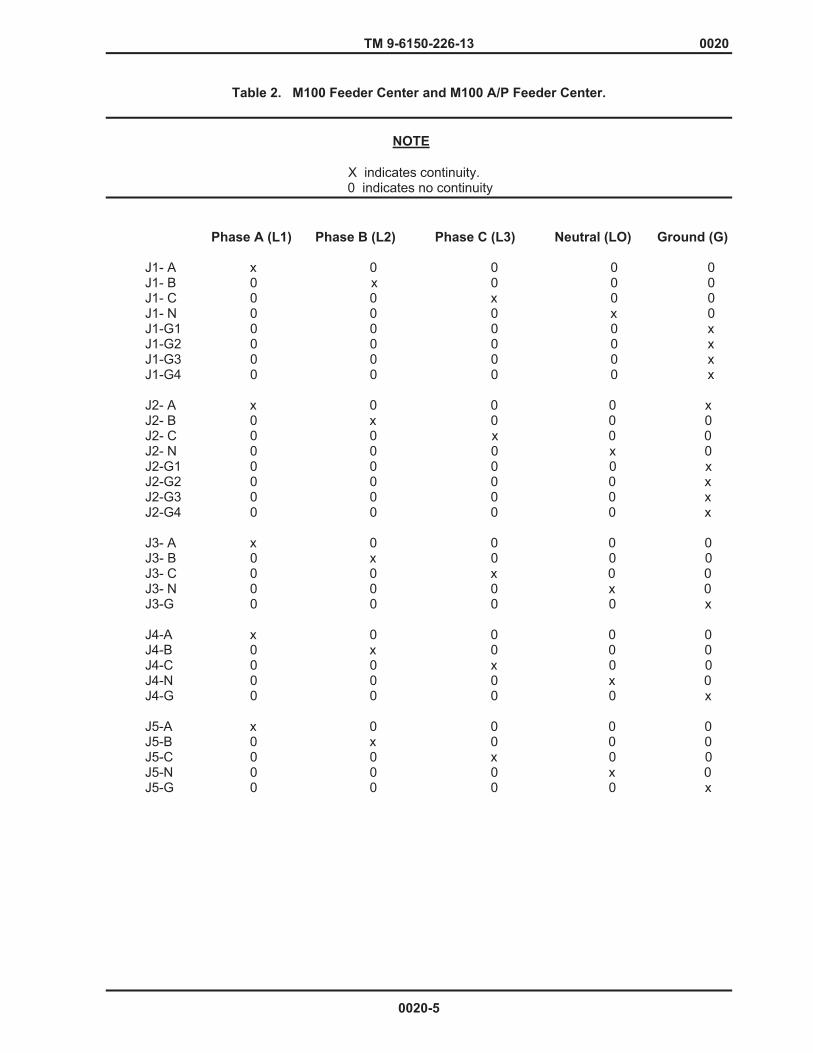
TM 9-6150-226-13 0020
Table 2. M100 Feeder Center and M100 A/P Feeder Center.
X indicates continuity. 0 indicates no continuity
Phase A (L1) Phase B (L2) Phase C (L3) Neutral (LO) Ground (G)
J1- A x 0 0 0 0 J1- B 0 x 0 0 0 J1- C 0 0 x 0 0 J1- N 0 0 0 x 0 J1-G1 0 0 0 0 x J1-G2 0 0 0 0 x J1-G3 0 0 0 0 x J1-G4 0 0 0 0 x J2- A x 0 0 0 x J2- B 0 x 0 0 0 J2- C 0 0 x 0 0 J2- N 0 0 0 x 0 J2-G1 0 0 0 0 x J2-G2 0 0 0 0 x J2-G3 0 0 0 0 x J2-G4 0 0 0 0 x J3- A x 0 0 0 0 J3- B 0 x 0 0 0 J3- C 0 0 x 0 0 J3- N 0 0 0 x 0 J3-G 0 0 0 0 x J4-A x 0 0 0 0 J4-B 0 x 0 0 0 J4-C 0 0 x 0 0 J4-N 0 0 0 x 0 J4-G 0 0 0 0 x J5-A x 0 0 0 0 J5-B 0 x 0 0 0 J5-C 0 0 x 0 0 J5-N 0 0 0 x 0 J5-G 0 0 0 0 x
NOTE
0020-5

TM 9-6150-226-13 0020
Table 2 (Cont). M100 Feeder Center and M100 A/P Feeder Center
X indicates continuity. 0 indicates no continuity. Phase A (L1) Phase B (L2) Phase C (L3) Neutral (LO) Ground (G)
J6-A x 0 0 0 0 J6-B 0 x 0 0 0 J6-C 0 0 x 0 0 J6-N 0 0 0 x 0 J6-G 0 0 0 0 x J7-A 0 0 x 0 0 J7-B 0 0 0 x 0 J7-C 0 0 0 0 x J8-A x 0 0 0 0 J8-B 0 0 0 x 0 J8-C 0 0 0 0 x
NOTE
0020-6
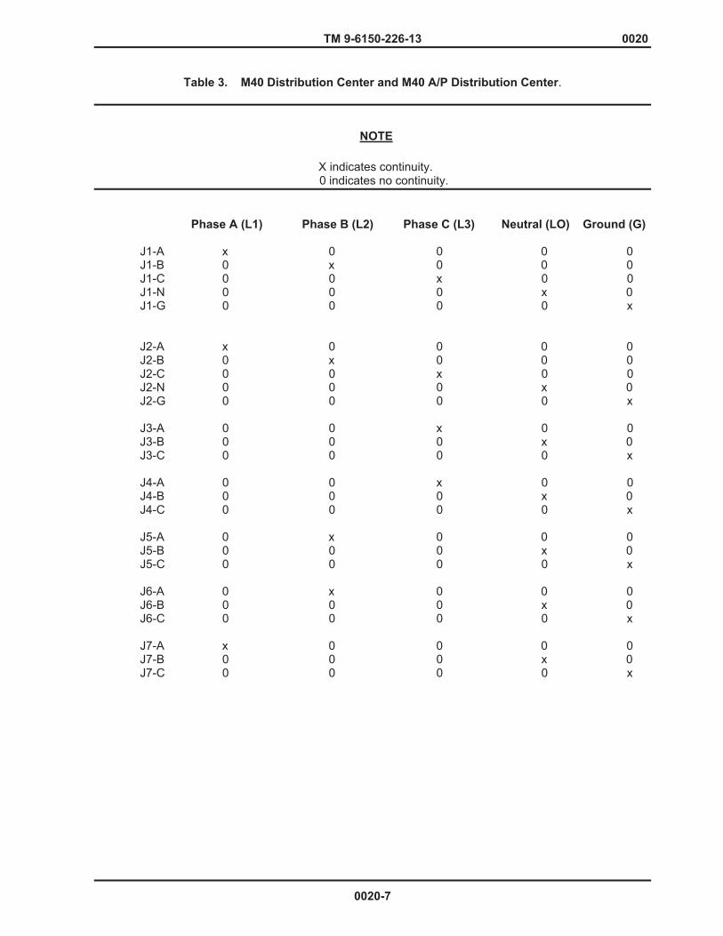
TM 9-6150-226-13 0020
Table 3. M40 Distribution Center and M40 A/P Distribution Center.
X indicates continuity. 0 indicates no continuity.
Phase A (L1) Phase B (L2) Phase C (L3) Neutral (LO) Ground (G)
J1-A x 0 0 0 0 J1-B 0 x 0 0 0 J1-C 0 0 x 0 0 J1-N 0 0 0 x 0 J1-G 0 0 0 0 x J2-A x 0 0 0 0 J2-B 0 x 0 0 0 J2-C 0 0 x 0 0 J2-N 0 0 0 x 0 J2-G 0 0 0 0 x J3-A 0 0 x 0 0 J3-B 0 0 0 x 0 J3-C 0 0 0 0 x
J4-A 0 0 x 0 0 J4-B 0 0 0 x 0 J4-C 0 0 0 0 x J5-A 0 x 0 0 0 J5-B 0 0 0 x 0 J5-C 0 0 0 0 x J6-A 0 x 0 0 0 J6-B 0 0 0 x 0 J6-C 0 0 0 0 x J7-A x 0 0 0 0 J7-B 0 0 0 x 0 J7-C 0 0 0 0 x
NOTE
0020-7
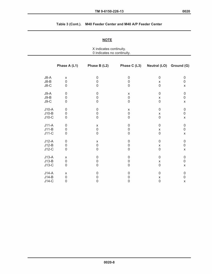
TM 9-6150-226-13 0020
Table 3 (Cont.). M40 Feeder Center and M40 A/P Feeder Center
X indicates continuity. 0 indicates no continuity.
Phase A (L1) Phase B (L2) Phase C (L3) Neutral (LO) Ground (G)
J8-A x 0 0 0 0 J8-B 0 0 0 x 0 J8-C 0 0 0 0 x J9-A 0 0 x 0 0 J9-B 0 0 0 x 0 J9-C 0 0 0 0 x J10-A 0 0 x 0 0 J10-B 0 0 0 x 0 J10-C 0 0 0 0 x J11-A 0 x 0 0 0 J11-B 0 0 0 x 0 J11-C 0 0 0 0 x J12-A 0 x 0 0 0 J12-B 0 0 0 x 0 J12-C 0 0 0 0 x
J13-A x 0 0 0 0 J13-B 0 0 0 x 0 J13-C 0 0 0 0 x J14-A x 0 0 0 0 J14-B 0 0 0 x 0 J14-C 0 0 0 0 x
NOTE
0020-8

TM 9-6150-226-13 0020
Table 4. M60 Distribution Center and M60 A/P Distribution Center.
X indicates continuity. 0 indicates no continuity.
Phase A (L1) Neutral (LO) Ground (G)
J1-A x 0 0 J1-N 0 x 0 J1-G1 0 0 x J1-G2 0 0 x J2-A x 0 0 J2-N 0 x 0 J2-G1 0 0 x J2-G2 0 0 x J3-A x 0 0 J3-B 0 x 0 J3-C 0 0 x J4-A x 0 0 J4-B 0 x 0 J4-C 0 0 x J5-A x 0 0 J5-B 0 x 0 J5-C 0 0 x J6-A x 0 0 J6-B 0 x 0 J6-C 0 0 x J7-A x 0 0 J7-B 0 x 0 J7-C 0 0 x J8-A x 0 0 J8-B 0 x 0 J8-C 0 0 x
END OF WORK PACKAGE
NOTE
0020-9/10 Blank

TM 9-6150-226-13 0021
FIELD LEVEL MAINTENANCE INSTRUCTIONS
DISE AND PDISE AUXILIARY CABLE ASSEMBLIES TEST
INITIAL SETUP: References Tools General Mechanic’s Automotive Tool Kit Equipment Conditions
(Item 1, WP 0035) None Personnel Required One
WARNING
High voltage is present in this system. DISE and PDISE support equipment using 120/208 VAC. Do not replace a connector assembly with the power on. Failure to observe warning may result in death or serious injury to personnel.
TEST 1. Disconnect both ends of cable from the DISE or PDISE equipment.
2. Refer to the applicable Table below and perform a continuity test on that cable.
3. If cable is defective, send to next higher level of maintenance.
The following lists only the Service, Extension, Pigtail, and Branch cable assemblies.
Table # Auxiliary Cable Assembly Continuity Checks
1………………………………………………. 200/100 Amp, 8 Pin/Wire Service/Feeder Cables 2……………………………………………… 40/60 Amp, 5 Pin/Wire Service/Feeder Cables
3………………………………………………. 200/100 Amp, 8 Pin/Wire Pigtail Cables
4………………………………………………. 40/60 Amp, 5 Pin/Wire Pigtail Cables
5………………………………………………. 60-Amp, 4 Pin/Wire Service/Feeder Cables
6………………………………………………. 60-Amp, 4 Pin/Wire Pigtail Cables
7……………………………………………… 20-Amp, 3 Pin/Wire Extension Cables 8 ……………………………………………… 20-Amp, 3 Pin/Wire Branch Circuit Cables
NOTE
0021-1

TM 9-6150-226-13 0021
WARNING
High voltage is present in this system. DISE and PDISE systems support equipment using 120/208 V ac. Do not rely on the color of the wire insulation for phase color coding. The insulation on the wires inside the cable jacket may vary depending on supplier. Wires will be color coded to designate the phases. Perform a continuity test to verify phase designation is in accordance with identified color. X indicates continuity 0 indicates no continuity
Table 1. 200/100-Amp, 8 Pin/Wire Service/Feeder Cables. P1-A P1-B P1-C P1-N P1-G1 P1-G2 P1-G3 P1-G4
P2-A x 0 0 0 0 0 0 0 P2-B 0 x 0 0 0 0 0 0 P2-C 0 0 x 0 0 0 0 0 P2-N 0 0 0 x 0 0 0 0 P2-G1 0 0 0 0 x x x x P2-G2 0 0 0 0 x x x x P2-G3 0 0 0 0 x x x x P2-G4 0 0 0 0 x x x x
Table 2. 40/60-Amp, 5 Pin/Wire Service/Feeder Cables. P1-A P1-B P1-C P1-N P1-G
P2-A x 0 0 0 0 P2-B 0 x 0 0 0 P2-C 0 0 x 0 0 P2-N 0 0 0 x 0 P2-G 0 0 0 0 x
NOTE
0021-2
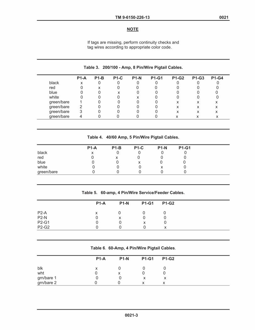
TM 9-6150-226-13 0021
If tags are missing, perform continuity checks and
tag wires according to appropriate color code.
Table 3. 200/100 - Amp, 8 Pin/Wire Pigtail Cables.
P1-A P1-B P1-C P1-N P1-G1 P1-G2 P1-G3 P1-G4
black x 0 0 0 0 0 0 0 red 0 x 0 0 0 0 0 0 blue 0 0 x 0 0 0 0 0 white 0 0 0 x 0 0 0 0 green/bare 1 0 0 0 0 x x x green/bare 2 0 0 0 0 x x x green/bare 3 0 0 0 0 x x x green/bare 4 0 0 0 0 x x x
Table 4. 40/60 Amp, 5 Pin/Wire Pigtail Cables. P1-A P1-B P1-C P1-N P1-G1 black x 0 0 0 0 red 0 x 0 0 0 blue 0 0 x 0 0 white 0 0 0 x 0 green/bare 0 0 0 0 0
Table 5. 60-amp, 4 Pin/Wire Service/Feeder Cables.
P1-A P1-N P1-G1 P1-G2
P2-A x 0 0 0 P2-N 0 x 0 0 P2-G1 0 0 x 0 P2-G2 0 0 0 x
Table 6. 60-Amp, 4 Pin/Wire Pigtail Cables. P1-A P1-N P1-G1 P1-G2
blk x 0 0 0 wht 0 x 0 0 grn/bare 1 0 0 x x grn/bare 2 0 0 x x
NOTE
0021-3

TM 9-6150-226-13 0021
Table 7. 20-Amp, 3 Pin/Wire Extension Cables
P1-A P1-B P1-C
P2-A x 0 0 P2-B 0 x 0 P2-C 0 0 x
Table 8. 20-Amp, 3 Pin/Wire Branch Circuit Cables. P1-A P1-B P1-C
P2-A x 0 0 P2-B 0 x 0 P2-C 0 0 x
P3-A x 0 0 P3-B 0 x 0 P3-C 0 0 x
P4-A x 0 0 P4-B 0 x 0 P4-C 0 0 x
P5-A x 0 0 P5-B 0 x 0 P5-C 0 0 x
END OF WORK PACKAGE
0021-4
TM 9-6150-226-13 0022
FIELD LEVEL MAINTENANCE INSTRUCTIONS DUST AND MOISTURE SLEEVE
REPLACE
INITIAL SETUP:
Tools References General Mechanic’s Automotive Tool Kit (Item 1, WP 0035) Materials/Parts Equipment Conditions None None
WARNING
High voltage is present in this system. DISE and PDISE support equipment using 120/208 VAC. Do not replace a connector assembly with the power on. Failure to observe warning may result in death or serious injury to personnel.
REPLACE 1. Remove nuts (Figure 1, Item 1), flat washers (Figure 1, Item 2), and screws (Figure 1, Item 3) securing sleeve plate (Figure 1, Item 4) to enclosure. 2. Remove locknut (Figure 1, Item 5) and bushing (Figure 1, Item 6).
3. Remove sleeve plate (4).
4. Remove dust and moisture sleeve (Figure 1, Item 7).
5. Install dust and moisture sleeve (7) and secure with sleeve plate (4), locknut (5), and bushing (6). 6. Secure sleeve plate (4) with nuts (1), flat washers (2), and screws (3).
0022-1
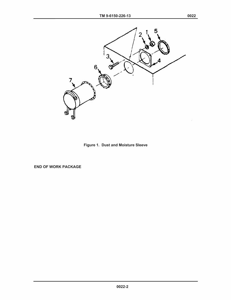
TM 9-6150-226-13 0022
Figure 1. Dust and Moisture Sleeve END OF WORK PACKAGE
0022-2

TM 9-61150-226-13 0023
FIELD LEVEL MAINTENANCE INSTRUCTIONS GASKET REPLACE
INITIAL SETUP:
Tools References General Mechanic’s Automotive Tool Kit WP 0015 (Item 1, WP 0035)
Materials/Parts Equipment Conditions Gasket Cement (item 1,WP 0038) Power shut down REPLACE
1. Remove lanyards (WP 0015).
2. Scrape off old gasket (1).
3. Clean surface of lid with solvent and rag 4. Coat surface of gasket (1) with adhesive. 5. On hinged end of lid, place gasket (1) on inside of lip (2). 6. Place gasket (1) on bottom of lid for other three sides. 7. Install lanyards (WP 0015).
0023-1
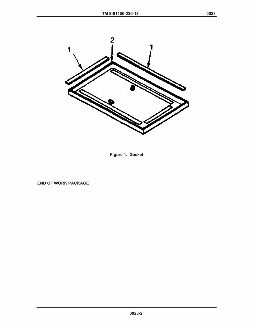
TM 9-61150-226-13 0023
Figure 1. Gasket END OF WORK PACKAGE
0023-2
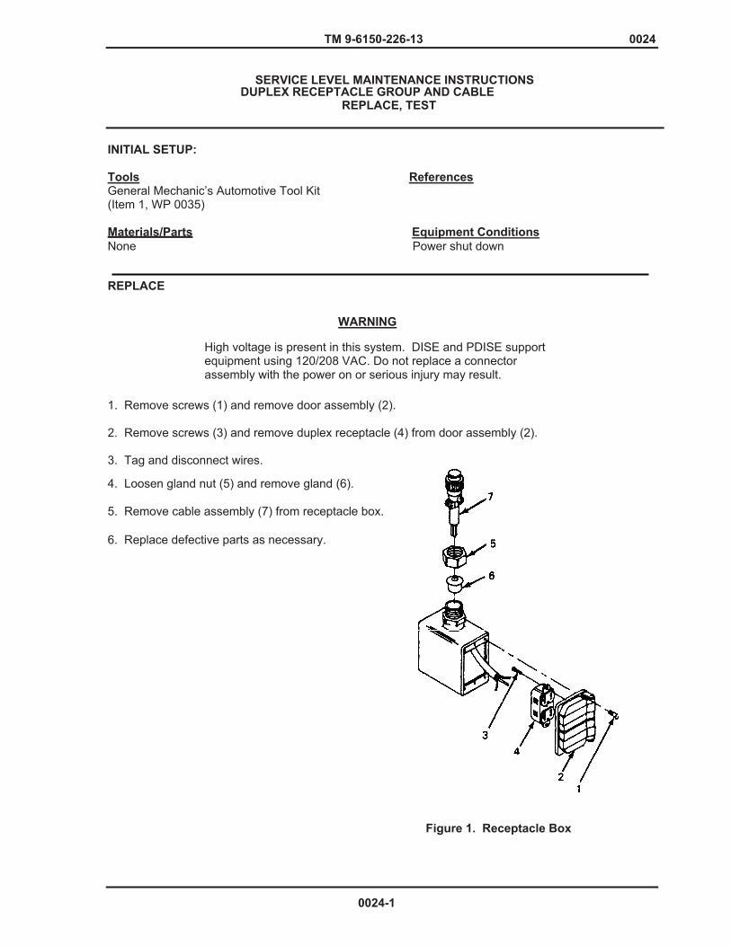
TM 9-6150-226-13 0024
SERVICE LEVEL MAINTENANCE INSTRUCTIONS
DUPLEX RECEPTACLE GROUP AND CABLE REPLACE, TEST
INITIAL SETUP:
Tools ReferencesGeneral Mechanic’s Automotive Tool Kit (Item 1, WP 0035) Materials/Parts Equipment Conditions None Power shut down REPLACE
WARNING
High voltage is present in this system. DISE and PDISE support equipment using 120/208 VAC. Do not replace a connector assembly with the power on or serious injury may result.
1. Remove screws (1) and remove door assembly (2).
2. Remove screws (3) and remove duplex receptacle (4) from door assembly (2).
3. Tag and disconnect wires. 4. Loosen gland nut (5) and remove gland (6).
5. Remove cable assembly (7) from receptacle box. 6. Replace defective parts as necessary.
Figure 1. Receptacle Box
0024-1
TM 9-6150-226-13 0024
7. Install cable assembly (7) in receptacle box.
8. Install gland (6) in place and secure with gland nut (5).
9. Remove tags and connect wires in accordance with Figure 2.
10. Install duplex receptacle (4) on door assembly (2) and secure with screws (3). 11. Place door assembly (2) on box and secure with screws.
TEST
WARNING
High voltage is present in this system. DISE and PDISE support equipment using 120/208 VAC. Do not attempt continuity checks with the power on or serious injury may result. Failure to do so may result in death or serious injury or equipment damage.
Refer to the following table to perform continuity test on the duplex receptacle.
Table 1. DUPLEX RECEPTACLE CONTINUITY CHECKS (see Figure 2) X indicates continuity. 0 indicates no continuity.
Duplex Receptacle
Phase Line Neutral Line Ground Line Input (Black Wire) (White Wire) (Green Wire) Connector (Short Slot) (Long T-slot) (Ground slot)
_____________________________________________________________________________
J1-A x 0 0 J1-B 0 x 0 J1-C 0 0 X
NOTE
0024-2
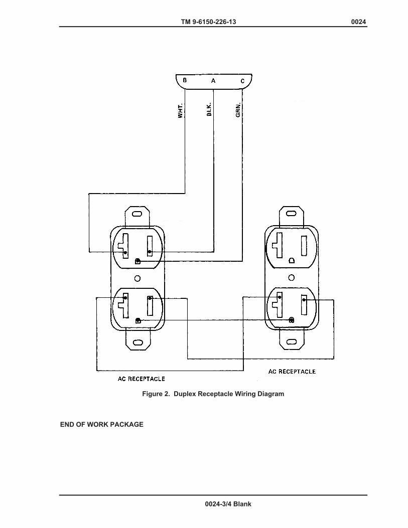
Verified Draft
TM 9-6150-226-13 0024
Figure 2. Duplex Receptacle Wiring Diagram END OF WORK PACKAGE
0024-3/4 Blank

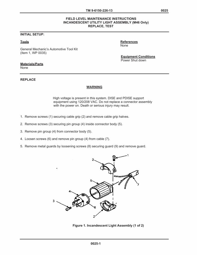
TM 9-6150-226-13 0025
FIELD LEVEL MAINTENANCE INSTRUCTIONS INCANDESCENT UTILITY LIGHT ASSEMBLY (M46 Only) REPLACE, TEST INITIAL SETUP:
Tools References None General Mechanic’s Automotive Tool Kit (Item 1, WP 0035) Equipment Conditions Power Shut down Materials/Parts None
REPLACE
WARNING
High voltage is present in this system. DISE and PDISE support
equipment using 120/208 VAC. Do not replace a connector assembly with the power on. Death or serious injury may result.
1. Remove screws (1) securing cable grip (2) and remove cable grip halves. 2. Remove screws (3) securing pin group (4) inside connector body (5). 3. Remove pin group (4) from connector body (5). 4. Loosen screws (6) and remove pin group (4) from cable (7). 5. Remove metal guards by loosening screws (8) securing guard (9) and remove guard.
Figure 1. Incandescent Light Assembly (1 of 2)
3
0025-1
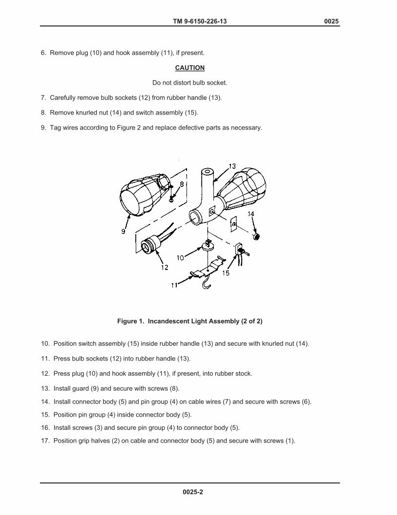
TM 9-6150-226-13 0025
6. Remove plug (10) and hook assembly (11), if present.
CAUTION
Do not distort bulb socket. 7. Carefully remove bulb sockets (12) from rubber handle (13). 8. Remove knurled nut (14) and switch assembly (15). 9. Tag wires according to Figure 2 and replace defective parts as necessary.
Figure 1. Incandescent Light Assembly (2 of 2)
10. Position switch assembly (15) inside rubber handle (13) and secure with knurled nut (14). 11. Press bulb sockets (12) into rubber handle (13). 12. Press plug (10) and hook assembly (11), if present, into rubber stock. 13. Install guard (9) and secure with screws (8).
14. Install connector body (5) and pin group (4) on cable wires (7) and secure with screws (6). 15. Position pin group (4) inside connector body (5). 16. Install screws (3) and secure pin group (4) to connector body (5). 17. Position grip halves (2) on cable and connector body (5) and secure with screws (1).
0025-2
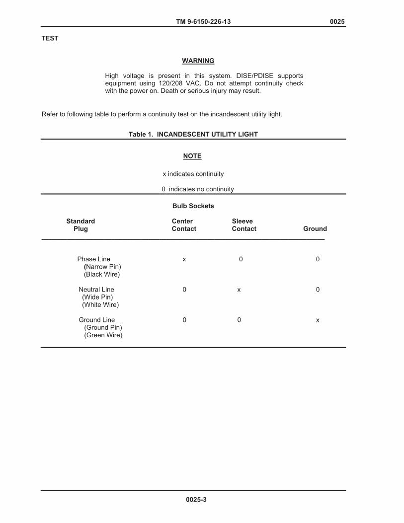
TM 9-6150-226-13 0025
TEST
WARNING High voltage is present in this system. DISE/PDISE supports equipment using 120/208 VAC. Do not attempt continuity check with the power on. Death or serious injury may result.
Refer to following table to perform a continuity test on the incandescent utility light.
Table 1. INCANDESCENT UTILITY LIGHT
x indicates continuity
0 indicates no continuity
Bulb Sockets
Standard Center Sleeve Plug Contact Contact Ground
_____________________________________________________________________________
Phase Line x 0 0 (Narrow Pin) (Black Wire)
Neutral Line 0 x 0 (Wide Pin) (White Wire)
Ground Line 0 0 x (Ground Pin) (Green Wire)
NOTE
0025-3
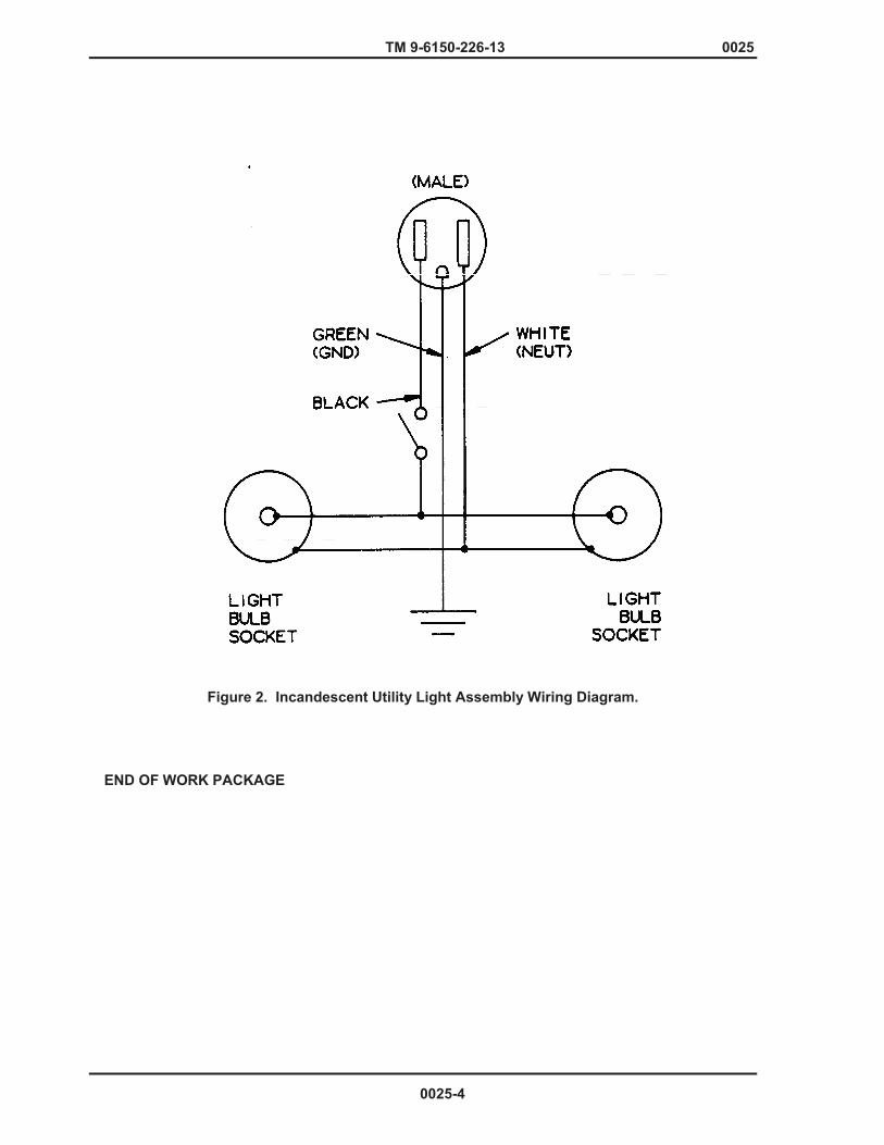
Verified Draft
TM 9-6150-226-13 0025
Figure 2. Incandescent Utility Light Assembly Wiring Diagram.
END OF WORK PACKAGE
0025-4
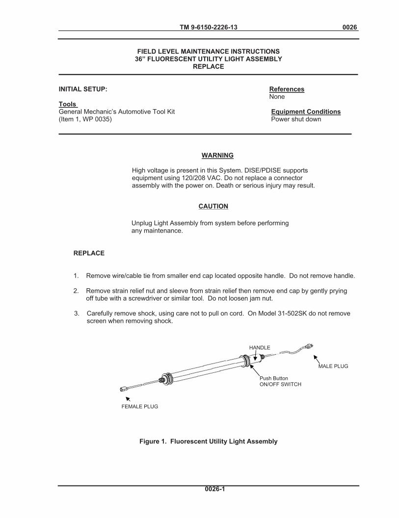
TM 9-6150-2226-13 0026
Push Button ON/OFF SWITCH
MALE PLUG
FEMALE PLUG
HANDLE
FIELD LEVEL MAINTENANCE INSTRUCTIONS
36” FLUORESCENT UTILITY LIGHT ASSEMBLY REPLACE
INITIAL SETUP: References None Tools General Mechanic’s Automotive Tool Kit Equipment Conditions (Item 1, WP 0035) Power shut down
WARNING
High voltage is present in this System. DISE/PDISE supports equipment using 120/208 VAC. Do not replace a connector assembly with the power on. Death or serious injury may result.
Unplug Light Assembly from system before performing any maintenance.
REPLACE 1. Remove wire/cable tie from smaller end cap located opposite handle. Do not remove handle. 2. Remove strain relief nut and sleeve from strain relief then remove end cap by gently prying off tube with a screwdriver or similar tool. Do not loosen jam nut.
3. Carefully remove shock, using care not to pull on cord. On Model 31-502SK do not remove screen when removing shock.
Figure 1. Fluorescent Utility Light Assembly
CAUTION
0026-1
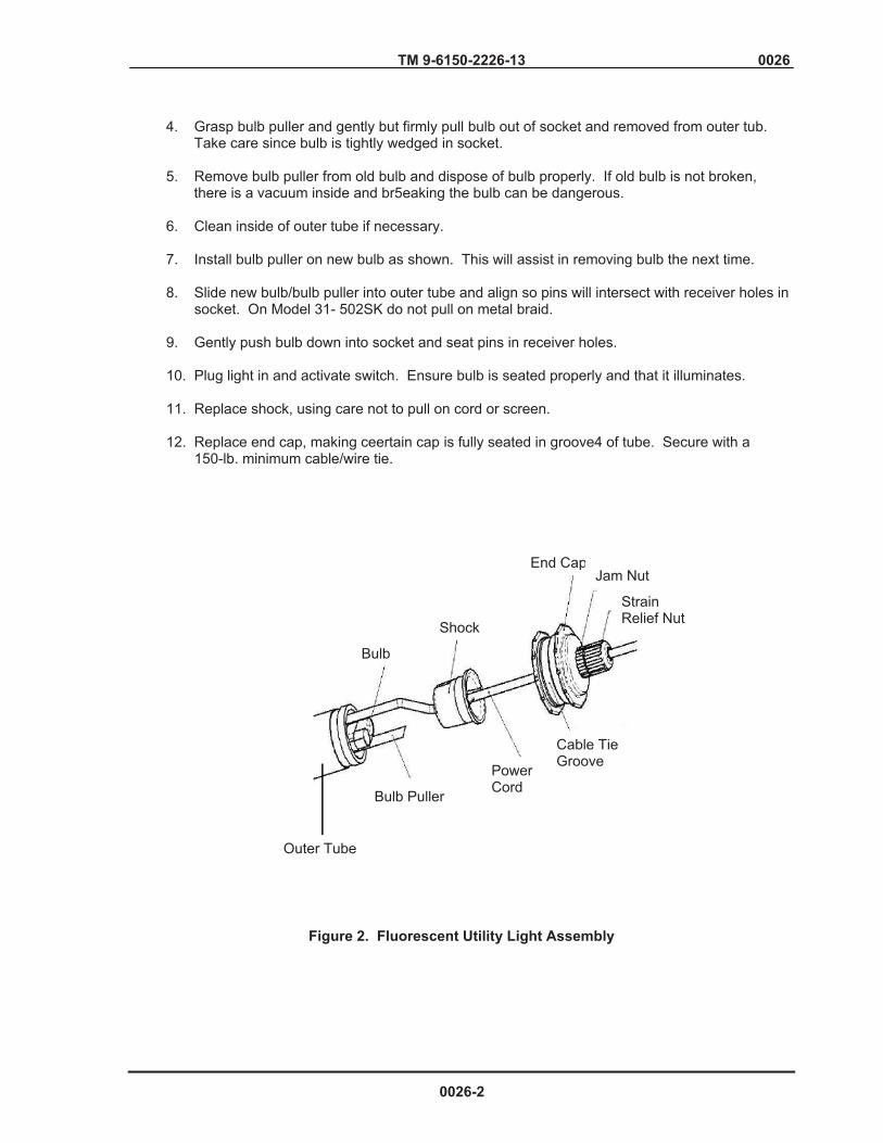
TM 9-6150-2226-13 0026
4. Grasp bulb puller and gently but firmly pull bulb out of socket and removed from outer tub. Take care since bulb is tightly wedged in socket. 5. Remove bulb puller from old bulb and dispose of bulb properly. If old bulb is not broken, there is a vacuum inside and br5eaking the bulb can be dangerous. 6. Clean inside of outer tube if necessary. 7. Install bulb puller on new bulb as shown. This will assist in removing bulb the next time. 8. Slide new bulb/bulb puller into outer tube and align so pins will intersect with receiver holes in socket. On Model 31- 502SK do not pull on metal braid. 9. Gently push bulb down into socket and seat pins in receiver holes. 10. Plug light in and activate switch. Ensure bulb is seated properly and that it illuminates. 11. Replace shock, using care not to pull on cord or screen. 12. Replace end cap, making ceertain cap is fully seated in groove4 of tube. Secure with a 150-lb. minimum cable/wire tie.
Figure 2. Fluorescent Utility Light Assembly
Outer Tube
Bulb
Bulb Puller
Shock
Power Cord
Cable Tie Groove
End CapJam Nut
Strain Relief Nut
0026-2

TM 9-6150-2226-13 0026
Figure 3. Fluorescent Utility Light Assembly END OF WORK PACKAGE
Bulb Pin Bulb Puller
Bulb
0026-3/4 Blank

TM 9-6150-226-13 0027
FIELD LEVEL MAINTENANCE INSTRUCTIONS UNIVERSAL ADAPTER- MOUNTING BOARD AND INPUT CONNECTOR
REPLACE, TEST
INITIAL SETUP:
Tools Equipment ConditionsGeneral Mechanic’s Automotive Tool Kit Power shut down (Item 1, WP 0035)
Reference WP 0015Materials/Parts None
WARNING
High voltage is present in this system. DISE and PDISE support equipment using 120/208 VAC. Do not replace a connector assembly with the power on. Death or serious injury may result.
CAUTION
Failure to support the universal adapter lid may result in damage to the hinges.
REPLACE
1. Remove lanyard assembly. (WP 0015)
2. Remove bolts (Figure 1, Item 5) securing terminal board (Item 6).
3. Remove terminal board (6) from universal adapter box.
4. Tag wires (7) according to the load terminal connection.
5. Remove nuts (8) and washers (9) and disconnect wires from bottom of load terminals (10).
6. Remove nuts (11), washers (12), and screws (13) securing input connector (14) to box and remove connector.
7. Insert input connector (14) through front of box and secure with nuts (11), washers (12), and screws (13).
8. Connect tagged wires (7) to bottom of load terminals according to Figure 2.
9. Position terminal board (6) inside universal adapter box and secure board with bolts (5).
10. Connect lanyard assembly. (WP 0015)
0027-1 Change 1

TM 9-6150-226-13 0027
Figure 1. Input Connector and Mounting Board
Change 1 0027-2

TM 9-6150-226-13 0027
WARNING
High voltage is present in this system. DISE and PDISE support equipment using 120/208 VAC. Do not attempt continuity check with the power on. Death or serious Injury may result.
TEST
Perform continuity test below.
NOTE
X indicates continuity
0 indicates no continuity
Table 1. UNIVERSAL ADAPTER CONTINUITY CHECKS (see Figure 2)
Input Out Connector Terminals
L1 L2 L3 LO G
J1-A X 0 0 0 0
J1-B 0 X 0 0 0
J1-C 0 0 X 0 0
J1-N 0 0 0 X 0
J1-G 0 0 0 0 X
0027-3 Change 1
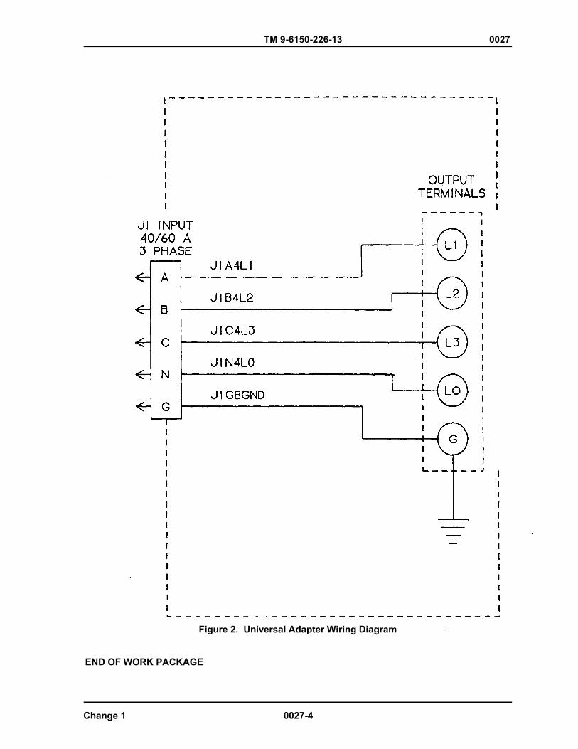
TM 9-6150-226-13 0027
Figure 2. Universal Adapter Wiring Diagram
END OF WORK PACKAGE
Change 1 0027-4
TM 9-6150-226-13 0028
FIELD LEVEL MAINTENANCE INSTRUCTIONS LOAD TERMINAL
REPLACE
INITIAL SETUP: References WP 0015 Tools General Mechanic’s Automotive Tool Kit Equipment Conditions (Item 1, WP 0035) None
Personnel Required One
WARNING
High voltage is present in this system. DISE and PDISE support equipment using 120/208 VAC. Do not replace a connector assembly with the power on. Death or serious injury may result
REPLACE
1. Remove lanyard assembly. (WP 0015) 2. Remove nuts (Figure 1, Item 1) and washers (Figure 1, Item 2) securing load terminal (Figure 1, Item 3) to terminal board (Figure 1, Item 4).
3. Remove load terminal (3).
4. Insert load terminal (3) through terminal board (4). 5. Secure load terminal (3) to terminal board (4) with nuts (1) and washers (2). 6. Install lanyard assembly (WP 0015).
0028-1

TM 9-6150-226-13 0028
Figure 1. Load Terminal
END OF WORK PACKAGE
0028-2
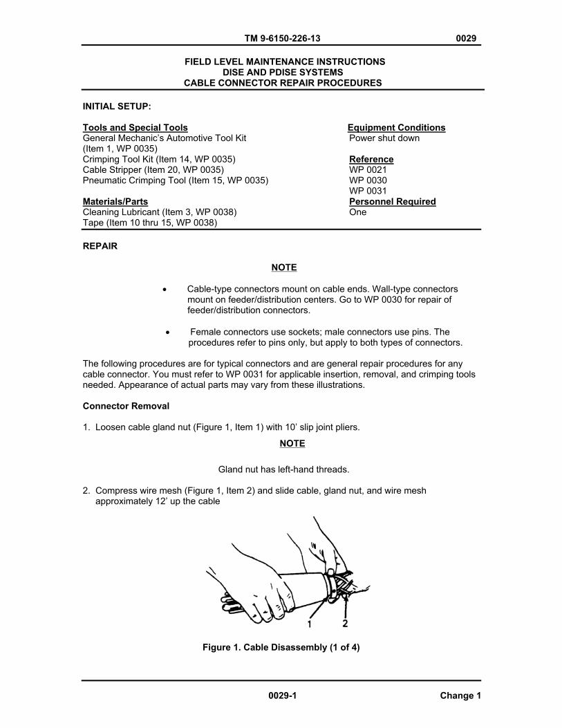
TM 9-6150-226-13 0029
FIELD LEVEL MAINTENANCE INSTRUCTIONS DISE AND PDISE SYSTEMS
CABLE CONNECTOR REPAIR PROCEDURES
INITIAL SETUP:
Tools and Special Tools Equipment Conditions General Mechanic’s Automotive Tool Kit Power shut down (Item 1, WP 0035) Crimping Tool Kit (Item 14, WP 0035) ReferenceCable Stripper (Item 20, WP 0035) WP 0021 Pneumatic Crimping Tool (Item 15, WP 0035) WP 0030 WP 0031Materials/Parts Personnel RequiredCleaning Lubricant (Item 3, WP 0038) OneTape (Item 10 thru 15, WP 0038)
REPAIR
NOTE
� Cable-type connectors mount on cable ends. Wall-type connectors mount on feeder/distribution centers. Go to WP 0030 for repair of feeder/distribution connectors.
� Female connectors use sockets; male connectors use pins. The procedures refer to pins only, but apply to both types of connectors.
The following procedures are for typical connectors and are general repair procedures for any cable connector. You must refer to WP 0031 for applicable insertion, removal, and crimping tools needed. Appearance of actual parts may vary from these illustrations.
Connector Removal
1. Loosen cable gland nut (Figure 1, Item 1) with 10’ slip joint pliers.
Gland nut has left-hand threads.
2. Compress wire mesh (Figure 1, Item 2) and slide cable, gland nut, and wire mesh approximately 12’ up the cable
Figure 1. Cable Disassembly (1 of 4)
NOTE
0029-1 Change 1

TM 9-6150-226-13 0029
3. Loosen three hex-socket screws (Figure 1, Item 3).
Figure 1. Cable Disassembly (2 of 4)
4. Remove connector head (Figure 1, Item 4) from connector body (Figure 1, Item 5).
Figure 1. Cable Disassembly (3 of 4)
5. Apply lubricant on cable directly behind connector and push cable forward into connector body (5) in order to force support group (Figure 1, Item 6) out.
Figure 1. Cable Disassembly (4 of 4)
Change 1 0029-2
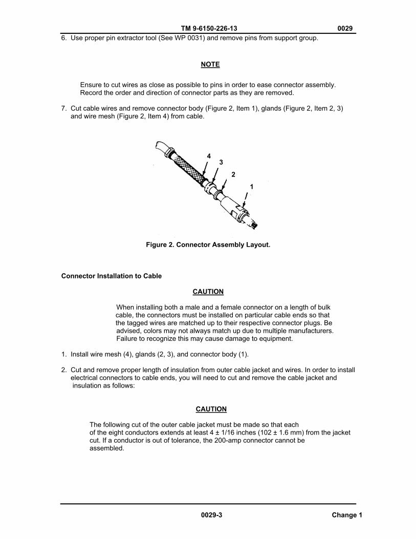
TM 9-6150-226-13 0029 6. Use proper pin extractor tool (See WP 0031) and remove pins from support group.
NOTE
Ensure to cut wires as close as possible to pins in order to ease connector assembly. Record the order and direction of connector parts as they are removed.
7. Cut cable wires and remove connector body (Figure 2, Item 1), glands (Figure 2, Item 2, 3) and wire mesh (Figure 2, Item 4) from cable.
2
34
1
Figure 2. Connector Assembly Layout.
Connector Installation to Cable
CAUTION
When installing both a male and a female connector on a length of bulk cable, the connectors must be installed on particular cable ends so that the tagged wires are matched up to their respective connector plugs. Be
advised, colors may not always match up due to multiple manufacturers. Failure to recognize this may cause damage to equipment.
1. Install wire mesh (4), glands (2, 3), and connector body (1).
2. Cut and remove proper length of insulation from outer cable jacket and wires. In order to install electrical connectors to cable ends, you will need to cut and remove the cable jacket and insulation as follows:
CAUTION
The following cut of the outer cable jacket must be made so that each of the eight conductors extends at least 4 ± 1/16 inches (102 ± 1.6 mm) from the jacket cut. If a conductor is out of tolerance, the 200-amp connector cannot be assembled.
0029-3 Change 1

TM 9-6150-226-13 0029
200-amp, 8 -Pin/Wire, Cables.
(a). Carefully cut and remove 4 inches of outer cable jacket from end of cable.
(b). Carefully cut and remove 7/8 inch of conductor insulation from end of each conductor.
(c). Continue to Step 3.
100-amp, 8-Pin/Wire, Cables.
(a). Carefully cut and remove 3-1/2 inches (89 mm) of outer cable jacket from end of cable.
(b). Carefully cut and remove 7/8 inch (22 mm) of conductor insulation from end of each conductor.
(c). Continue to Step 3.
40/60-amp, 5-Pin/Wire, Cables.
(a). Carefully cut and remove 3-1/2 inches (89 mm) of outer cable jacket from end of cable.
(b). Cut off ½ inch (13 mm) from phases A, B, C, and neutral conductor (the four large conductors).
(c). Carefully cut and remove 7/8 inch (22 mm) of conductor insulation from end of each conductor.
(d). Continue to Step 3.
60-amp, 4-Pin/Wire, Cables.
(a). Carefully cut and remove 3 inches (76 mm) of outer cable jacket from end of cable.
(b). Carefully cut and remove 7/8 inch (22 mm) of conductor insulation from end of each conductor.
(c). Continue to Step 3.
20-amp, 3-Pin/Wire, Cables.
(a). Carefully cut and remove 1/2 inch (13 mm) of outer cable jacket from end of cable.
(b). Carefully cut and remove 3/8 inch (10 mm) of conductor insulation from end of each conductor.
(c). Continue to Step 3.
3. Use a multi-meter to determine correct pin-to-wire installation.
4. Tag wires according to their designation.
Change 1 0029-4
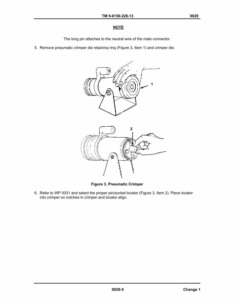
TM 9-6150-226-13 0029
NOTE
The long pin attaches to the neutral wire of the male connector.
5. Remove pneumatic crimper die retaining ring (Figure 3, Item 1) and crimper die.
1
2
Figure 3. Pneumatic Crimper
6. Refer to WP 0031 and select the proper pin/socket locator (Figure 3, Item 2). Place locator into crimper so notches in crimper and locator align.
0029-5 Change 1
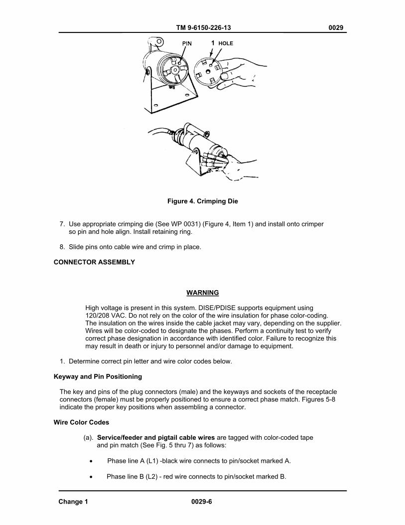
TM 9-6150-226-13 0029
1 HOLE
Figure 4. Crimping Die
7. Use appropriate crimping die (See WP 0031) (Figure 4, Item 1) and install onto crimper so pin and hole align. Install retaining ring.
8. Slide pins onto cable wire and crimp in place.
CONNECTOR ASSEMBLY
WARNING
High voltage is present in this system. DISE/PDISE supports equipment using 120/208 VAC. Do not rely on the color of the wire insulation for phase color-coding. The insulation on the wires inside the cable jacket may vary, depending on the supplier. Wires will be color-coded to designate the phases. Perform a continuity test to verify correct phase designation in accordance with identified color. Failure to recognize this may result in death or injury to personnel and/or damage to equipment.
1. Determine correct pin letter and wire color codes below.
Keyway and Pin Positioning
The key and pins of the plug connectors (male) and the keyways and sockets of the receptacle connectors (female) must be properly positioned to ensure a correct phase match. Figures 5-8 indicate the proper key positions when assembling a connector.
Wire Color Codes
(a). Service/feeder and pigtail cable wires are tagged with color-coded tape and pin match (See Fig. 5 thru 7) as follows:
� Phase line A (L1) -black wire connects to pin/socket marked A.
� Phase line B (L2) - red wire connects to pin/socket marked B.
Change 1 0029-6

TM 9-6150-226-13 0029
� Phase line C (L3) - blue wire connects to pin/socket marked C.
� Neutral line (LO) - white wire connects to pin/socket marked N
NOTE If there are one or more ground wires, connect to pins marked G1, G2, G3, or G4 as applicable.
� Ground lines – green (or bare) wires connect to pins/sockets marked G.
Figure 5. 200 and 100-amp, 8-wire Connector Face/ Key Positioning
0029-7 Change 1
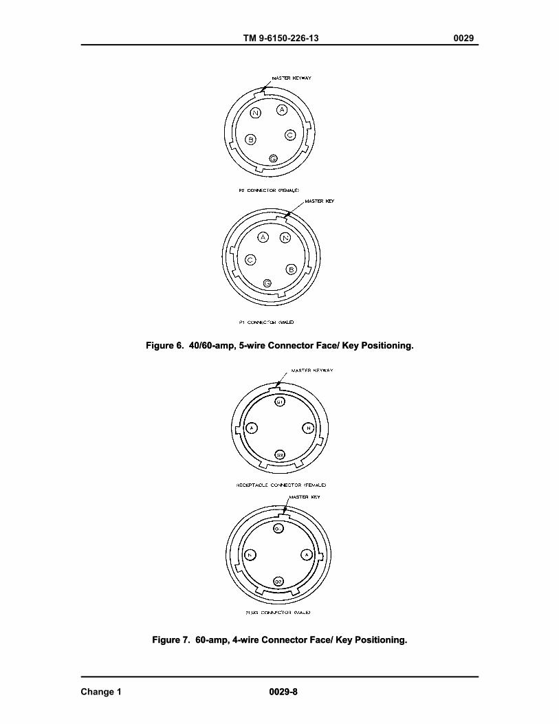
TM 9-6150-226-13 0029
Figure 6. 40/60-amp, 5-wire Connector Face/ Key Positioning.Figure 6. 40/60-amp, 5-wire Connector Face/ Key Positioning.
Figure 7. 60-amp, 4-wire Connector Face/ Key Positioning. Figure 7. 60-amp, 4-wire Connector Face/ Key Positioning.
Change 1 0029-8 0029-8
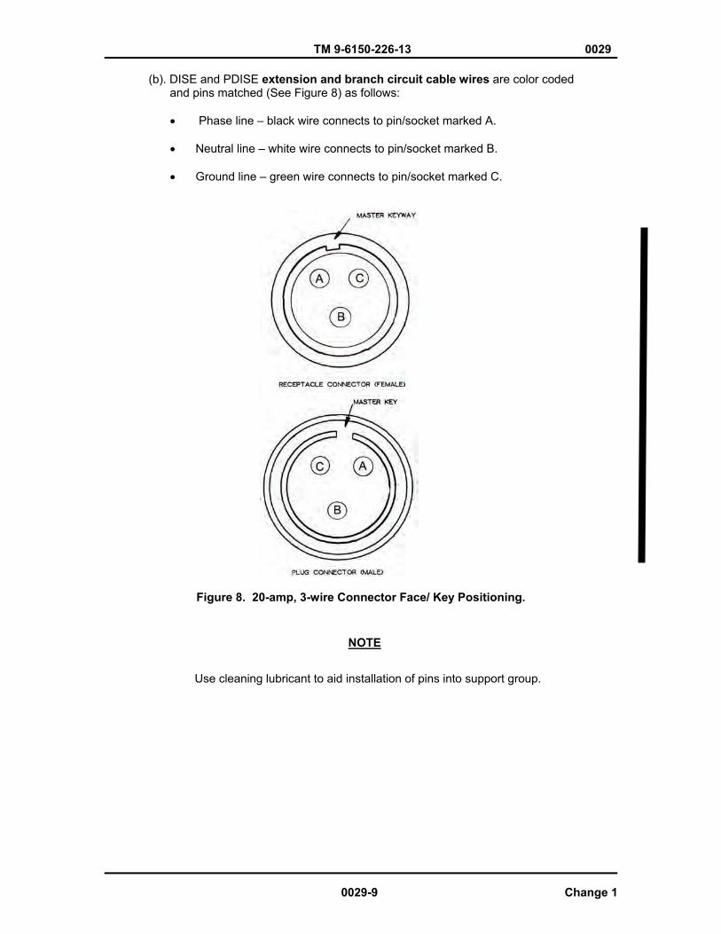
TM 9-6150-226-13 0029
(b). DISE and PDISE extension and branch circuit cable wires are color coded and pins matched (See Figure 8) as follows:
� Phase line – black wire connects to pin/socket marked A.
� Neutral line – white wire connects to pin/socket marked B.
� Ground line – green wire connects to pin/socket marked C.
Figure 8. 20-amp, 3-wire Connector Face/ Key Positioning.
NOTE
Use cleaning lubricant to aid installation of pins into support group.
0029-9 Change 1

TM 9-6150-226-13 0029
1 2
Figure 9. Installing Pin with Insertion Tool
3. Use proper insertion tool/s (WP 0031) and insert pins (Figure 9, Item 2) into support group (Figure 9, Item 1).
4. Determine correct pin-to-key positioning on new connector as stated above and shown in Figures 5 through 8.
NOTE
See the following alternate method for inserting pins collectively into the support group for the 100-amp, 8-pin; 40/60-amp, 5-pin; and 60-amp, 4-pin cable connectors. If you are not working these cables, continue to Step 5.
a. Start the A-pin into support group (6).
b. Start the N-pin into support group (6).
c. Slide support group (6) halfway over the A- and N-pins.
d. Start the B-pin into support group (6).
e. Start the C-pin into support group (6).
f. Slide support group (6) as far possible over all the pins.
g. Rock support group (6) toward the A-pin until it locks into position.
h. Rock support group (6) toward the N-pin until it locks into position.
i. Rock support group 96) toward the N-pin until it locks into position.
j. Grasp the C-pin wire and push the wire toward support group (6) while rocking the support group toward the C-pin until it locks into position.
k. Grasp the B-pin wire and push the wire toward support group (6) while rocking the support group toward the B-pin until it locks into position.
Change 1 0029-10
TM 9-6150-226-13 0029 l. Select a G-pin wire nearest to its support group (6) hole. Use long-nosed pliers to grasp the pin and insert the pin into its hole and lock position.
m. Insert remaining G-pins into support group (6) as described above.
5. Slide connector body (Figure 1, Item 5) down cable and position support group (Figure 1, Item 6) and connector body together.
6. Install connector head (Figure 1, Item 4) on connector body (Figure 1, Item 5).
7. Install hex-socket screws (Figure 1, Item 3).
NOTE
Cable gland nut has left-hand threads.
8. Slide glands (Figure 2, Items 2 & 3), wire mesh, (Figure 2, Item 4), and cable gland nut (Figure 1, Item 1) into connector body (Figure 1, Item 5) and tighten nut.
9. Use a multi-meter and perform a continuity test to verify correct assembly and pin seating. (See WP 0021 for cable continuity readings)
END OF WORK PACKAGE
0029-11/12 Blank Change 1

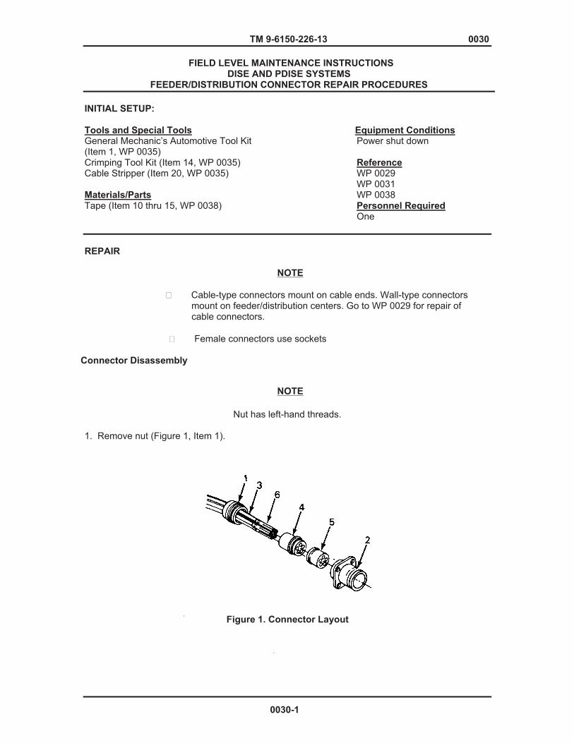
TM 9-6150-226-13 0030
FIELD LEVEL MAINTENANCE INSTRUCTIONS DISE AND PDISE SYSTEMS
FEEDER/DISTRIBUTION CONNECTOR REPAIR PROCEDURES
INITIAL SETUP:
Tools and Special Tools Equipment Conditions General Mechanic’s Automotive Tool Kit Power shut down (Item 1, WP 0035) Crimping Tool Kit (Item 14, WP 0035) Reference Cable Stripper (Item 20, WP 0035) WP 0029 WP 0031 Materials/Parts WP 0038 Tape (Item 10 thru 15, WP 0038) Personnel Required One REPAIR
� Cable-type connectors mount on cable ends. Wall-type connectors mount on feeder/distribution centers. Go to WP 0029 for repair of cable connectors.
� Female connectors use sockets
Connector Disassembly
Nut has left-hand threads.
1. Remove nut (Figure 1, Item 1).
NOTE
NOTE
Figure 1. Connector Layout
0030-1

TM 9-6150-226-13 0030 2. Remove wires (3), rear support group (4), and forward support group (5).
3. Remove forward support group (5) from pins (6).
4. Use removal tool (See WP 0031) and remove pins (6) from rear support group (4).
5. Replace defective parts as per WP 0038.
Connector Assembly
1. Install wires and pins (6) into rear support group (4).
Pins should lock into place when seated properly.
2. Position forward support group (5) over pins.
� Ensure position markings on rear and forward support groups match. � Forward support group (5) and connector are keyed to fit together.
3. Refer to WP 0031 for proper connector-face key positioning and install rear support group (4) and forward support group (5) into connector (2).
Nut has left-hand threads.
4. Install nut (1) on connector (2). END OF WORK PACKAGE
NOTE
NOTE
NOTE
0030-2
TM 9-6150-226-13 0031
FIELD LEVEL MAINTENANCE INSTRUCTIONS DISE AND PDISE SYSTEMS
GENERAL WIRING MAINTENANCE / WIRING DIAGRAMS
GENERAL
This section provides procedures to be followed for the repair and reference to fabrication of DISE and PDISE cable assemblies to the extent authorized at the Field maintenance level described in the Maintenance Allocation Chart (MAC). Use the following information listed in this WP to aid in maintenance corresponding to WP 0029 and WP 0030.
DISE and PDISE cables are designed for use in moist climatic conditions; cable splices are unauthorized. Cable assembly repair is limited to shortening the cable by cutting off the damaged portion and reattaching the connector.
Wiring diagrams are provided for general repair methods consisting of replacing wire leads, cables, harnesses, terminals, connectors, etc., rather than splicing wires, bending ends to form terminals, and other make shift procedures. Make shift repair procedures may be appropriate for emergency field repairs, but should be properly repaired as soon as possible.
Determine the serviceability of an item by comparing its physical, mechanical, and/or electrical characteristics with established standards through examination. MOS 52D, Power Generator equipment repairer, is authorized to perform all Field Level maintenance on DISE/PDISE equipment.
COMMON TOOLS AND EQUIPMENT
For authorized common tools and equipment refer to the Modified Table of Organization and Equipment (MTOE) applicable to your field.
REPAIR PARTS SPECIAL TOOLS, TEST AND SUPPORT EQUIPMENT
Refer to WP 0034, Maintenance Allocation Chart (MAC); TM 9-6150-226- 23P, Repair Parts and Special Tools List; to support equipment for Field Level maintenance.
GENERAL MAINTENANCE PROCEDURES
WARNING
High voltage is present in this system. DISE and PDISE support equipment using 120/208 VAC. Do not rely on the color of the wire insulation for phase color-coding. The insulation on the wires inside the cable jacket may vary, depending on the supplier. Wires will NOT always be color coded to designate the phases. Perform a continuity test to verify correct phase designation in accordance with identified color and/or pin designation
CAUTION
When installing both a male and a female connector on a length of bulk cable, the connectors must be installed on particular cable ends so that the tagged wires are matched up to their respective connector plugs. Be
advised, colors may not always match up due to multiple manufacturers. Failure to recognize this may cause damage to equipment.
0031- 1 Change 1
TM 9-6150-226-13 0031
Insulating Joints.
The preferred method of insulating bare electrical joints is by using insulation sleeving. To apply, slide a piece of insulation sleeving over the wire lead before making the joint. Make the joint then slide the insulation sleeving over the joint and shrink in place with heat gun.
Crimping Terminals.
DISE/PDISE may or may not require the use of terminals. To install a terminal, strip 1/4-1/2 inch (0.6-1.3 cm) of insulation from the end of the wire lead. Insert bare wire lead end into the shank of the terminal. Crimp the shank securely onto the wire lead.
WARNING
Solder and flux contain materials which are hazardous to health. Avoid breathing vapors or fumes from soldering operations. Perform operations only in well ventilated areas. Wash hands with soap and water after handling solder and flux. Wear thermal gloves and protective goggles or face shield to protect against bums.
Soldering Connections.
Wire connections must be made mechanically sound before they are soldered; solder alone does not provide sufficient strength to prevent breakage. Joining surfaces of connections to be soldered must be clean and bright. Flux should be brushed onto the joint before soldering. Wires should always be heated with a soldering iron to the point at which the solder will melt completely when touched to joint and flow into all parts of the joint. Excessive build up of solder on the joint should be avoided or removed.
Splicing Wire.
Splicing is the last means necessary to repair a broken or cut wire. To repair broken or cut wires that are otherwise sound, the mating ends can be stripped and spliced by using a crimped splice or by wrapping the stripped wire lead ends onto themselves then soldering, followed by proper insulating.
Connector Crimping Tools
The cable and wall mount connectors have pins (male) or sockets (female) that attach to the wires with a four-indent crimp. Table 1 identifies which tool to crimp each type and size of connector. Table 2 lists the various insertion, removal, locator, and crimp tools spoken of in WP’s 0029 and 0030 repair actions.
Feeder/Distribution Center Connectors (Wall-Mount Type)
To determine the correct wire length, correct stripping of wire, and correct selection of pins/sockets, refer to Table 3 or 4. These tables list the connector by type of center and connector position on the center. The table then directs you to the appropriate figure in for information necessary to repair and/or fabricate the connector and/or cable.
Change 1 0031- 2

TM 9-6150-226-13 0031
NOTE
Cable-type connectors mount on cable ends. Wall- type connectors mount on the feeder/distribution centers Use needle-nose pliers to install pins or sockets which do not have a special installation tool listed.
0031- 3 Change 1
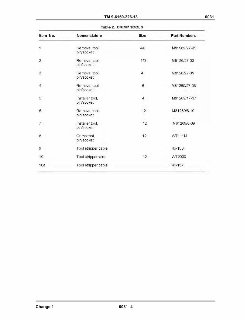
TM 9-6150-226-13 0031
Change 1 0031- 4
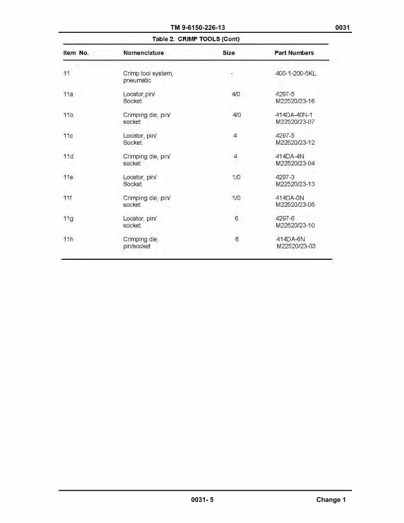
TM 9-6150-226-13 0031
0031- 5 Change 1
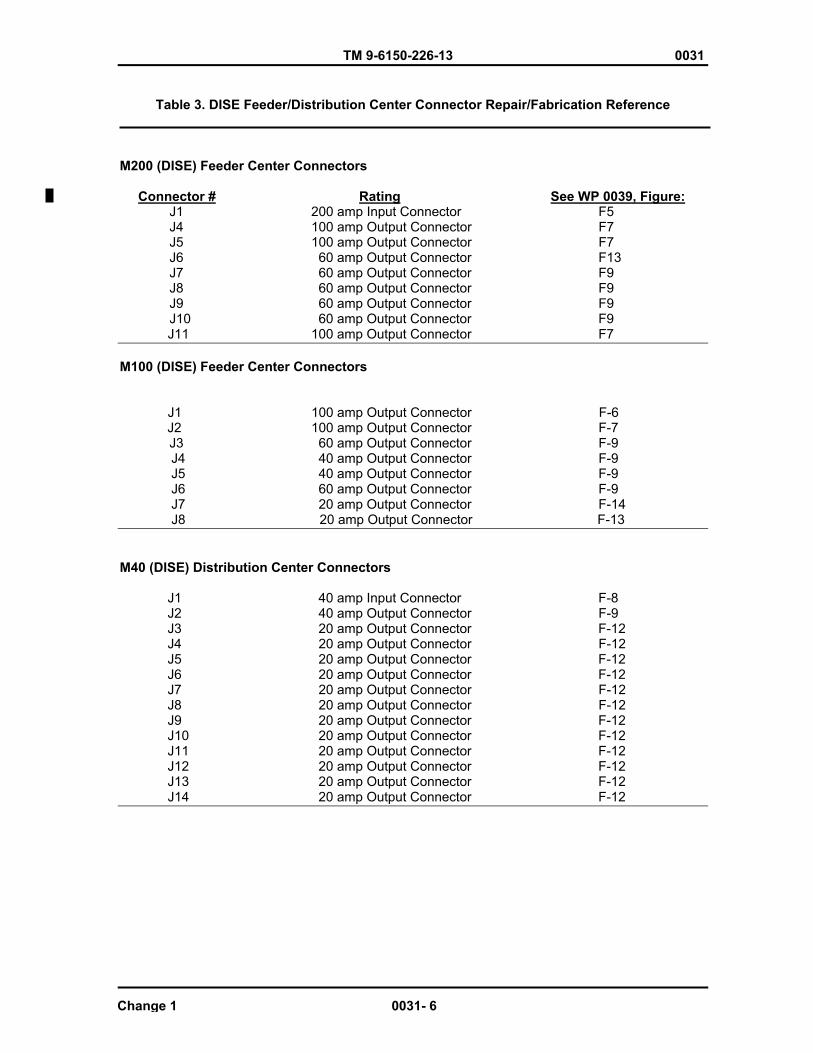
TM 9-6150-226-13 0031
Table 3. DISE Feeder/Distribution Center Connector Repair/Fabrication Reference
M200 (DISE) Feeder Center Connectors
Connector # Rating See WP 0039, Figure:J1 200 amp Input Connector F5 J4 100 amp Output Connector F7 J5 100 amp Output Connector F7 J6 60 amp Output Connector F13 J7 60 amp Output Connector F9 J8 60 amp Output Connector F9 J9 60 amp Output Connector F9 J10 60 amp Output Connector F9
J11 100 amp Output Connector F7
M100 (DISE) Feeder Center Connectors
J1 100 amp Output Connector F-6
J2 100 amp Output Connector F-7 J3 60 amp Output Connector F-9
J4 40 amp Output Connector F-9 J5 40 amp Output Connector F-9 J6 60 amp Output Connector F-9 J7 20 amp Output Connector F-14
J8 20 amp Output Connector F-13
M40 (DISE) Distribution Center Connectors
J1 40 amp Input Connector F-8 J2 40 amp Output Connector F-9 J3 20 amp Output Connector F-12 J4 20 amp Output Connector F-12 J5 20 amp Output Connector F-12 J6 20 amp Output Connector F-12 J7 20 amp Output Connector F-12 J8 20 amp Output Connector F-12 J9 20 amp Output Connector F-12 J10 20 amp Output Connector F-12 J11 20 amp Output Connector F-12 J12 20 amp Output Connector F-12
J13 20 amp Output Connector F-12 J14 20 amp Output Connector F-12
Change 1 0031- 6
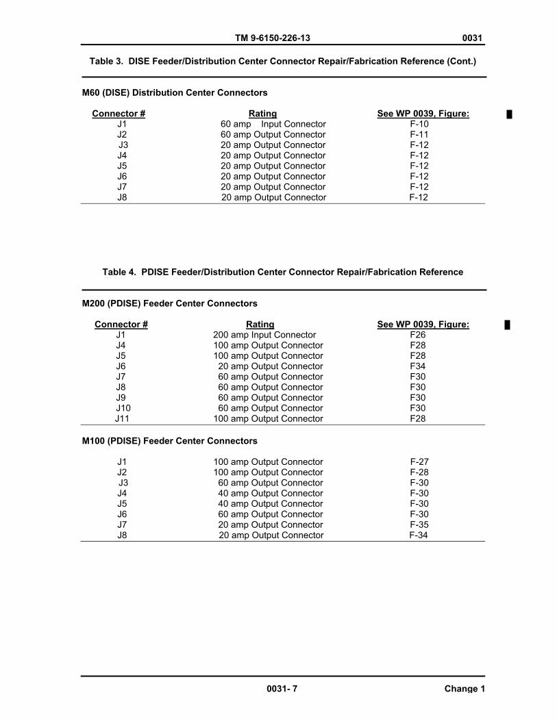
TM 9-6150-226-13 0031
Table 3. DISE Feeder/Distribution Center Connector Repair/Fabrication Reference (Cont.)
M60 (DISE) Distribution Center Connectors
Connector # Rating See WP 0039, Figure:J1 60 amp Input Connector F-10
J2 60 amp Output Connector F-11 J3 20 amp Output Connector F-12
J4 20 amp Output Connector F-12 J5 20 amp Output Connector F-12 J6 20 amp Output Connector F-12 J7 20 amp Output Connector F-12
J8 20 amp Output Connector F-12
Table 4. PDISE Feeder/Distribution Center Connector Repair/Fabrication Reference
M200 (PDISE) Feeder Center Connectors
Connector # Rating See WP 0039, Figure:J1 200 amp Input Connector F26 J4 100 amp Output Connector F28 J5 100 amp Output Connector F28 J6 20 amp Output Connector F34 J7 60 amp Output Connector F30 J8 60 amp Output Connector F30 J9 60 amp Output Connector F30 J10 60 amp Output Connector F30
J11 100 amp Output Connector F28
M100 (PDISE) Feeder Center Connectors
J1 100 amp Output Connector F-27 J2 100 amp Output Connector F-28
J3 60 amp Output Connector F-30 J4 40 amp Output Connector F-30 J5 40 amp Output Connector F-30 J6 60 amp Output Connector F-30 J7 20 amp Output Connector F-35
J8 20 amp Output Connector F-34
0031- 7 Change 1

TM 9-6150-226-13 0031
Table 4. PDISE Feeder/Distribution Center Connector Repair/Fabrication Reference (Cont)
M40 (PDISE) Distribution Center Connectors
Connector # Rating See WP 0039, Figure: J1 40 amp Input Connector F-29 J2 40 amp Output Connector F-30 J3 20 amp Output Connector F-33 J4 20 amp Output Connector F-33 J5 20 amp Output Connector F-33 J6 20 amp Output Connector F-33 J7 20 amp Output Connector F-33 J8 20 amp Output Connector F-33 J9 20 amp Output Connector F-33 J10 20 amp Output Connector F-33 J11 20 amp Output Connector F-33 J12 20 amp Output Connector F-33
J13 20 amp Output Connector F-33 J14 20 amp Output Connector F-33
M60 (DISE) Distribution Center Connectors
J1 60 amp Input Connector F-31 J2 60 amp Output Connector F-32
J3 20 amp Output Connector F-33 J4 20 amp Output Connector F-33 J5 20 amp Output Connector F-33 J6 20 amp Output Connector F-33 J7 20 amp Output Connector F-33
J8 20 amp Output Connector F-33
WIRING DIAGRAMS
NOTE
The following wiring diagrams are representations of data plates found on the inside of the feeder/distribution centers. Individual auxiliary components wiring diagrams are found in their respective Work Packages.
Change 1 0031- 8
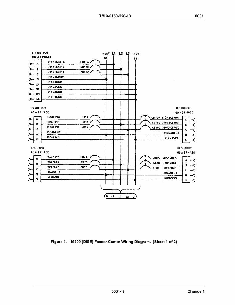
TM 9-6150-226-13 0031
Figure 1. M200 (DISE) Feeder Center Wiring Diagram. (Sheet 1 of 2)
0031- 9 Change 1
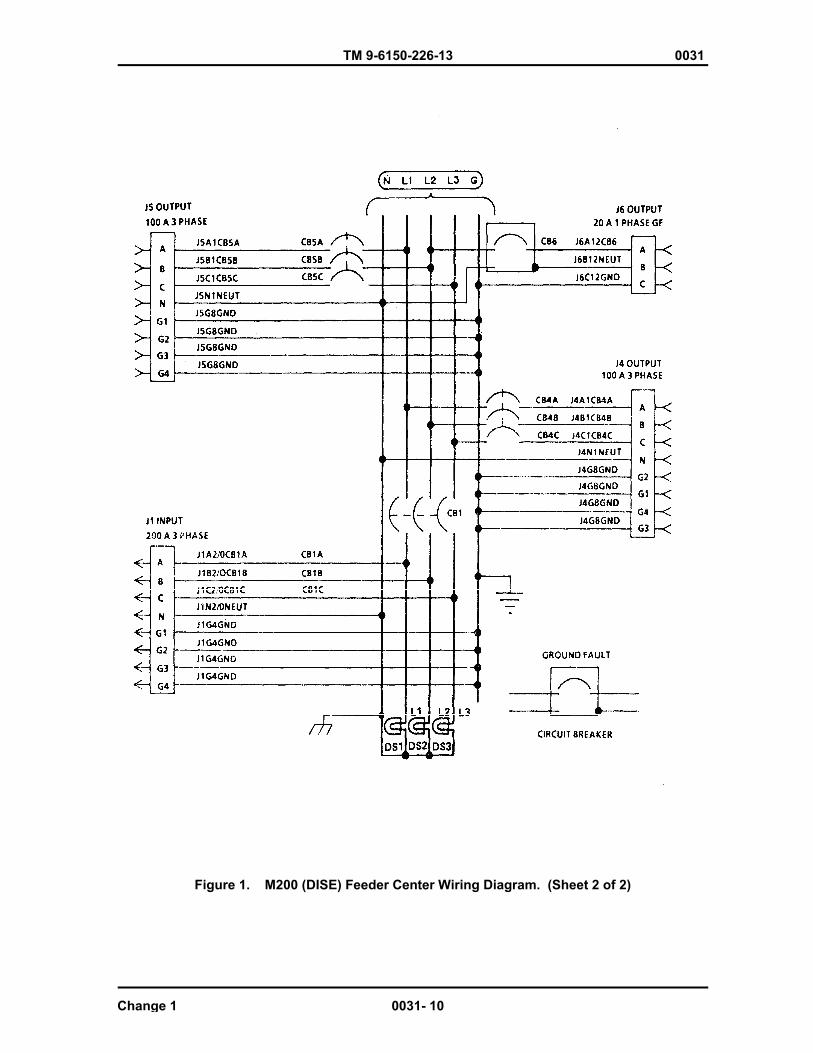
TM 9-6150-226-13 0031
Figure 1. M200 (DISE) Feeder Center Wiring Diagram. (Sheet 2 of 2)
Change 1 0031- 10

TM 9-6150-226-13 0031
Figure 2. M100 (DISE) Feeder Center Wiring Diagram
0031-11 Change 1
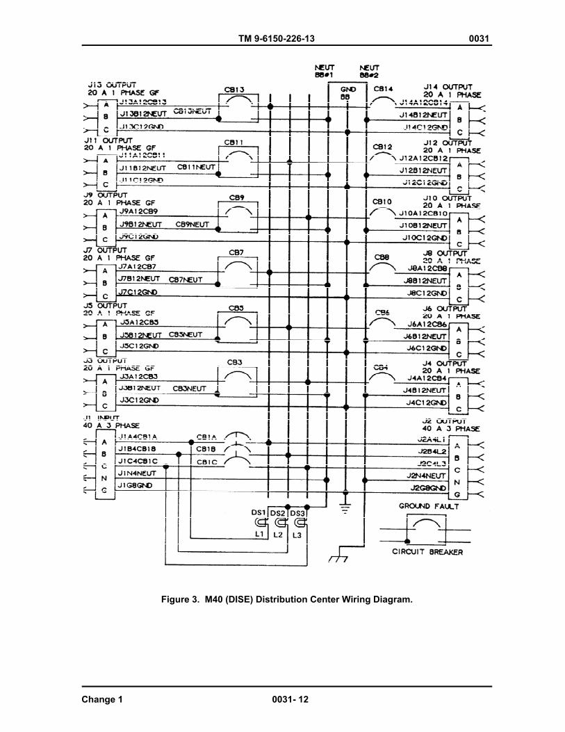
TM 9-6150-226-13 0031
Figure 3. M40 (DISE) Distribution Center Wiring Diagram.
Change 1 0031- 12

TM 9-6150-226-13 0031
0031- 13 Change 1
Figure 4. M60 (DISE) Distribution Center Wiring Diagram
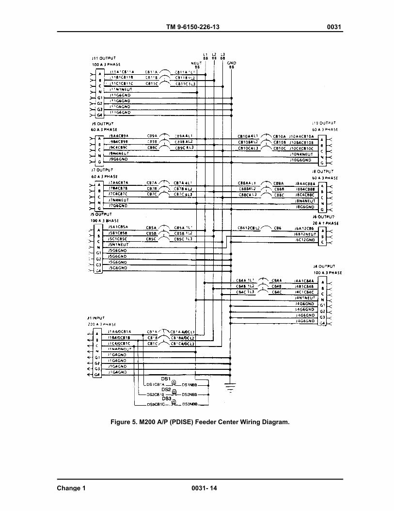
TM 9-6150-226-13 0031
Figure 5. M200 A/P (PDISE) Feeder Center Wiring Diagram.
Change 1 0031- 14

TM 9-6150-226-13 0031
0031- 15 Change 1
Figure 6. M100 A/P (PDISE) Feeder Center Wiring Diagram.
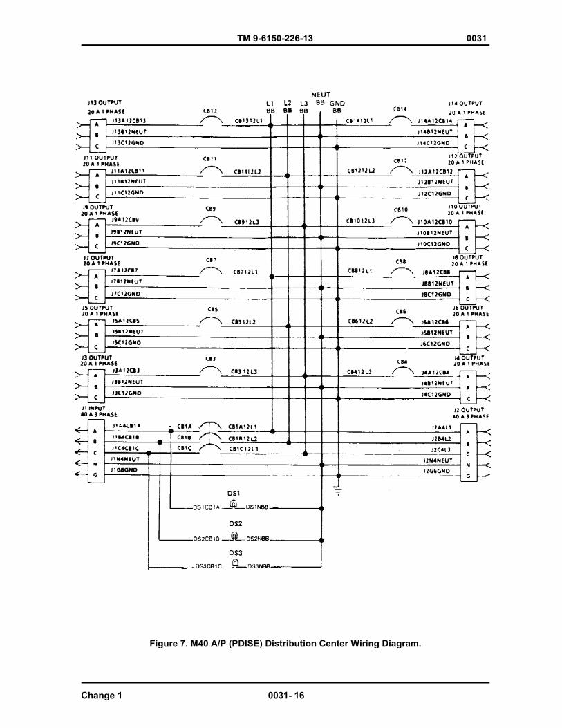
TM 9-6150-226-13 0031
Figure 7. M40 A/P (PDISE) Distribution Center Wiring Diagram.
Change 1 0031- 16
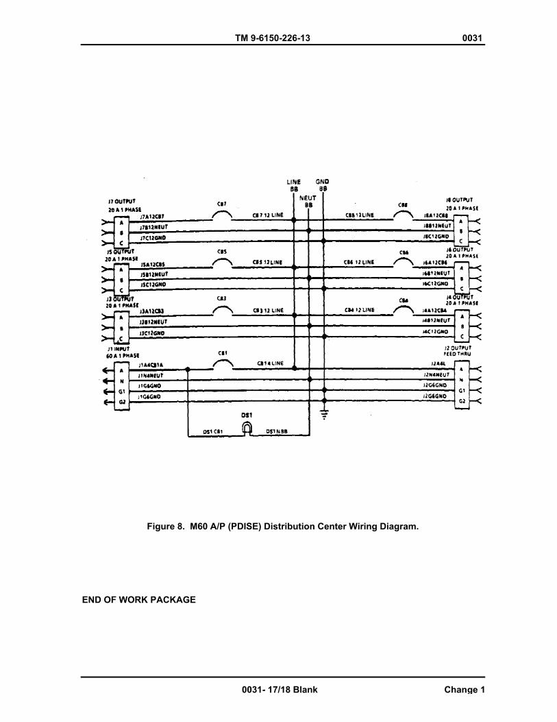
TM 9-6150-226-13 0031
Figure 8. M60 A/P (PDISE) Distribution Center Wiring Diagram.
END OF WORK PACKAGE
0031- 17/18 Blank Change 1

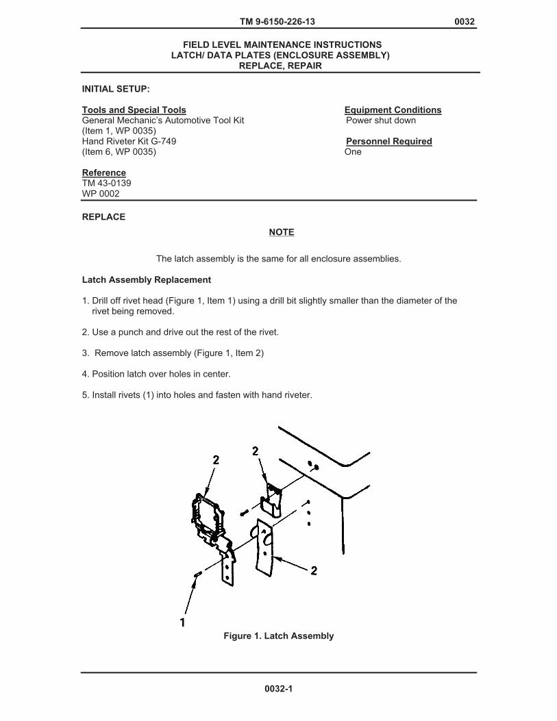
TM 9-6150-226-13 0032
FIELD LEVEL MAINTENANCE INSTRUCTIONS LATCH/ DATA PLATES (ENCLOSURE ASSEMBLY)
REPLACE, REPAIR
INITIAL SETUP:
Tools and Special Tools Equipment Conditions General Mechanic’s Automotive Tool Kit Power shut down (Item 1, WP 0035) Hand Riveter Kit G-749 Personnel Required (Item 6, WP 0035) One Reference TM 43-0139 WP 0002 REPLACE
The latch assembly is the same for all enclosure assemblies.
Latch Assembly Replacement 1. Drill off rivet head (Figure 1, Item 1) using a drill bit slightly smaller than the diameter of the rivet being removed. 2. Use a punch and drive out the rest of the rivet. 3. Remove latch assembly (Figure 1, Item 2) 4. Position latch over holes in center. 5. Install rivets (1) into holes and fasten with hand riveter.
Figure 1. Latch Assembly
NOTE
0032-1
TM 9-6150-226-13 0032
Data Plate Replacement Data plates contain vital Warning, Informative, and Identification information. Any plate that is badly damaged, faded, or in any way missing and/or depreciated, should be replaced immediately. Should data plate be missing, see WP 0002 for exact placement on individual feeder/distribution centers. 1. To replace data plates, use a drill bit slightly smaller than the diameter of the rivet being removed. 2. Drill the rivets out and remove the old plate. 3. Align holes in replacement plate and install new rivets with hand riveter REPAIR 1. Minor dents and bent edges can be straightened using common sheet metal repair procedures. 2. Should touch up or refinishing be necessary, see TM 43-0139, Painting Instructions for Army Material. END OF WORK PACKAGE
0032-2

Chapter 7
SUPPORTING INFORMATION

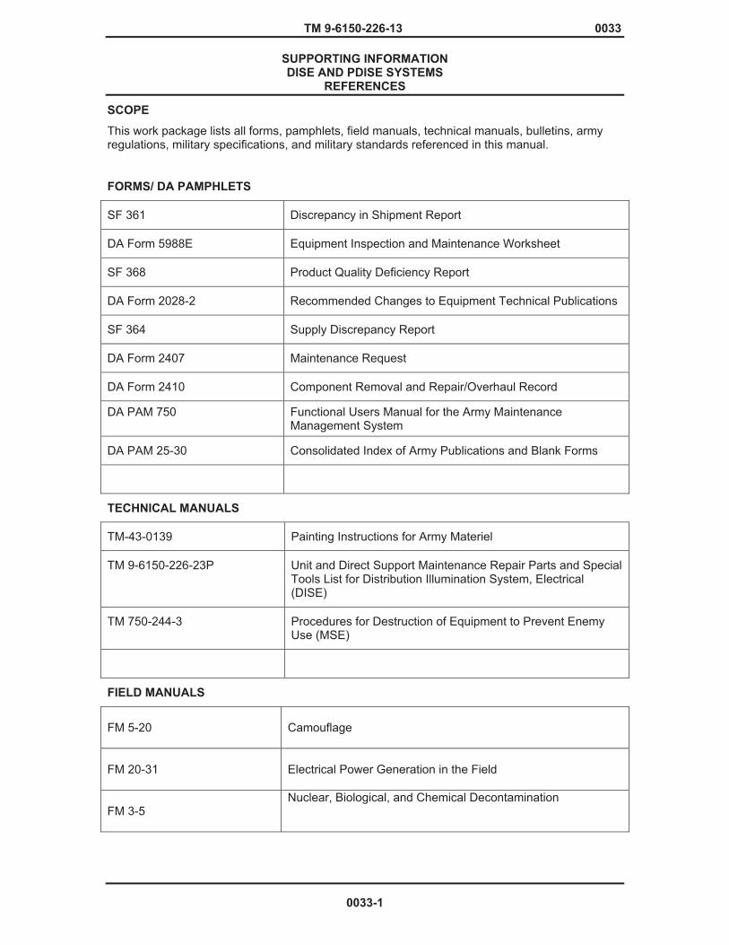
TM 9-6150-226-13 0033
SUPPORTING INFORMATION DISE AND PDISE SYSTEMS
REFERENCES
SCOPE
This work package lists all forms, pamphlets, field manuals, technical manuals, bulletins, army regulations, military specifications, and military standards referenced in this manual.
FORMS/ DA PAMPHLETS
SF 361 Discrepancy in Shipment Report
DA Form 5988E Equipment Inspection and Maintenance Worksheet
SF 368 Product Quality Deficiency Report
DA Form 2028-2 Recommended Changes to Equipment Technical Publications
SF 364 Supply Discrepancy Report
DA Form 2407 Maintenance Request
DA Form 2410 Component Removal and Repair/Overhaul Record
DA PAM 750 Functional Users Manual for the Army Maintenance Management System
DA PAM 25-30 Consolidated Index of Army Publications and Blank Forms
TECHNICAL MANUALS
TM-43-0139 Painting Instructions for Army Materiel
TM 9-6150-226-23P Unit and Direct Support Maintenance Repair Parts and Special Tools List for Distribution Illumination System, Electrical (DISE)
TM 750-244-3 Procedures for Destruction of Equipment to Prevent Enemy Use (MSE)
FIELD MANUALS
FM 5-20 Camouflage
FM 20-31 Electrical Power Generation in the Field
FM 3-5 Nuclear, Biological, and Chemical Decontamination
0033-1

TM 9-6150-226-13 0033
MILITARY SPECIFICATIONS
NONE
END OF WORK PACKAGE
0033-2

TM 9-6150-226-13 0034
SUPPORTING INFORMATION DISE AND PDISE SYSTEMS
INTRODUCTION FOR STANDARD MAINTENANCE ALLOCATION CHART (MAC)
THE ARMY MAINTENANCE SYSTEM
This introduction provides a general explanation of all maintenance and repair functions authorized at the two maintenance levels under the Two-Level Maintenance System concept.
This MAC (immediately following the introduction) designates overall authority and responsibility for the performance of maintenance functions on the identified end item or component. The application of the maintenance functions to the end item or component shall be consistent with the capacities and capabilities of the designated maintenance levels, which are shown on the MAC in column (4) as:
Field – includes three subcolumns, Crew maintenance (C), Service maintenance (O), and Field maintenance (F).
Sustainment – includes two subcolumns, Below Depot (H) and Depot (D)
The tools and test equipment requirements (immediately following the MAC) list the tools and test equipment (both special tools and common tool sets) required for each maintenance function as referenced from the MAC.
The remarks (immediately following the tools and test equipment requirements) contain supplemental instructions and explanatory notes for a particular maintenance function.
MAINTENANCE FUNCTIONS
Maintenance functions are limited to and defined as follows:
1. Inspect. To determine the serviceability of an item by comparing its physical, mechanical, and/or electrical characteristics with established standards through examination (e.g., by sight, sound, or feel). This includes scheduled inspection and gauging and evaluation of cannon tubes.
2. Test. To verify serviceability by measuring the mechanical, pneumatic, hydraulic, or electrical characteristics of an item and comparing those characteristics with prescribed standards on a scheduled basis, i.e., load testing of lift devices and hydrostatic testing of pressure hoses.
3. Service. Operations required periodically to keep an item in proper operating condition; e.g., to clean (includes decontaminate, when required), to preserve, to drain, to paint, or to replenish fuel, lubricants, chemical fluids, or gases. This includes scheduled exercising and purging of recoil mechanisms. The following are examples of service functions:
� Unpack. To remove from packing box for service or when required for the performance of maintenance operations. � Repack. To return item to packing box after service and other maintenance operations. � Clean. To rid the item of contamination. � Touch up. To spot paint scratched or blistered surfaces. � Mark. To restore obliterated identification.
4. Adjust. To maintain or regulate, within prescribed limits, by bringing into proper position, or by setting the operating characteristics to specified parameters.
0034-1
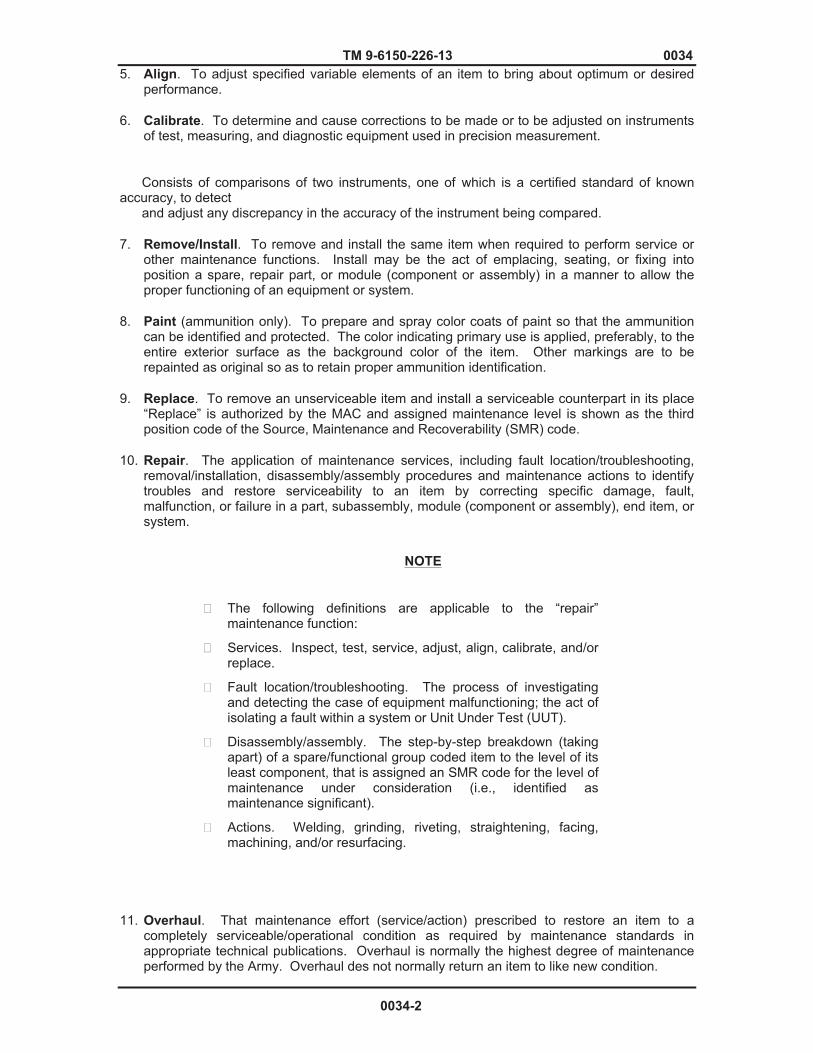
TM 9-6150-226-13 0034 5. Align. To adjust specified variable elements of an item to bring about optimum or desired
performance.
6. Calibrate. To determine and cause corrections to be made or to be adjusted on instruments of test, measuring, and diagnostic equipment used in precision measurement.
Consists of comparisons of two instruments, one of which is a certified standard of known accuracy, to detect and adjust any discrepancy in the accuracy of the instrument being compared.
7. Remove/Install. To remove and install the same item when required to perform service or other maintenance functions. Install may be the act of emplacing, seating, or fixing into position a spare, repair part, or module (component or assembly) in a manner to allow the proper functioning of an equipment or system.
8. Paint (ammunition only). To prepare and spray color coats of paint so that the ammunition can be identified and protected. The color indicating primary use is applied, preferably, to the entire exterior surface as the background color of the item. Other markings are to be repainted as original so as to retain proper ammunition identification.
9. Replace. To remove an unserviceable item and install a serviceable counterpart in its place “Replace” is authorized by the MAC and assigned maintenance level is shown as the third position code of the Source, Maintenance and Recoverability (SMR) code.
10. Repair. The application of maintenance services, including fault location/troubleshooting, removal/installation, disassembly/assembly procedures and maintenance actions to identify troubles and restore serviceability to an item by correcting specific damage, fault, malfunction, or failure in a part, subassembly, module (component or assembly), end item, or system.
� The following definitions are applicable to the “repair” maintenance function:
� Services. Inspect, test, service, adjust, align, calibrate, and/or replace.
� Fault location/troubleshooting. The process of investigating and detecting the case of equipment malfunctioning; the act of isolating a fault within a system or Unit Under Test (UUT).
� Disassembly/assembly. The step-by-step breakdown (taking apart) of a spare/functional group coded item to the level of its least component, that is assigned an SMR code for the level of maintenance under consideration (i.e., identified as maintenance significant).
� Actions. Welding, grinding, riveting, straightening, facing, machining, and/or resurfacing.
11. Overhaul. That maintenance effort (service/action) prescribed to restore an item to a completely serviceable/operational condition as required by maintenance standards in appropriate technical publications. Overhaul is normally the highest degree of maintenance performed by the Army. Overhaul des not normally return an item to like new condition.
NOTE
0034-2
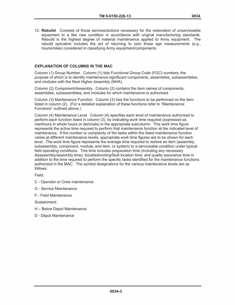
TM 9-6150-226-13 0034
12. Rebuild. Consists of those services/actions necessary for the restoration of unserviceable equipment to a like new condition in accordance with original manufacturing standards. Rebuild is the highest degree of material maintenance applied to Army equipment. The rebuild operation includes the act of returning to zero those age measurements (e.g., hours/miles) considered in classifying Army equipment/components.
EXPLANATION OF COLUMNS IN THE MAC
Column (1) Group Number. Column (1) lists Functional Group Code (FGC) numbers, the purpose of which is to identify maintenance significant components, assemblies, subassemblies, and modules with the Next Higher Assembly (NHA).
Column (2) Component/Assembly. Column (2) contains the item names of components, assemblies, subassemblies, and modules for which maintenance is authorized.
Column (3) Maintenance Function. Column (3) lists the functions to be performed on the item listed in column (2). (For a detailed explanation of these functions refer to “Maintenance Functions” outlined above.)
Column (4) Maintenance Level. Column (4) specifies each level of maintenance authorized to perform each function listed in column (3), by indicating work time required (expressed as manhours in whole hours or decimals) in the appropriate subcolumn. This work time figure represents the active time required to perform that maintenance function at the indicated level of maintenance. If the number or complexity of the tasks within the listed maintenance function varies at different maintenance levels, appropriate work time figures are to be shown for each level. The work time figure represents the average time required to restore an item (assembly, subassembly, component, module, end item, or system) to a serviceable condition under typical field operating conditions. This time includes preparation time (including any necessary disassembly/assembly time), troubleshooting/fault location time, and quality assurance time in addition to the time required to perform the specific tasks identified for the maintenance functions authorized in the MAC. The symbol designations for the various maintenance levels are as follows:
Field:
C - Operator or Crew maintenance
O - Service Maintenance
F - Field Maintenance
Sustainment:
H – Below Depot Maintenance
D - Depot Maintenance
0034-3
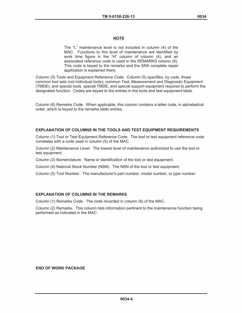
TM 9-6150-226-13 0034
The “L” maintenance level is not included in column (4) of the MAC. Functions to this level of maintenance are identified by work time figure in the “H” column of column (4), and an associated reference code is used in the REMARKS column (6). This code is keyed to the remarks and the SRA complete repair application is explained there.
Column (5) Tools and Equipment Reference Code. Column (5) specifies, by code, those common tool sets (not individual tools); common Test, Measurement and Diagnostic Equipment (TMDE); and special tools, special TMDE, and special support equipment required to perform the designated function. Codes are keyed to the entries in the tools and test equipment table.
Column (6) Remarks Code. When applicable, this column contains a letter code, in alphabetical order, which is keyed to the remarks table entries.
EXPLANATION OF COLUMNS IN THE TOOLS AND TEST EQUIPMENT REQUIREMENTS
Column (1) Tool or Test Equipment Reference Code. The tool or test equipment reference code correlates with a code used in column (5) of the MAC.
Column (2) Maintenance Level. The lowest level of maintenance authorized to use the tool or test equipment.
Column (3) Nomenclature. Name or identification of the tool or test equipment.
Column (4) National Stock Number (NSN). The NSN of the tool or test equipment.
Column (5) Tool Number. The manufacturer's part number, model number, or type number.
EXPLANATION OF COLUMNS IN THE REMARKS
Column (1) Remarks Code. The code recorded in column (6) of the MAC.
Column (2) Remarks. This column lists information pertinent to the maintenance function being performed as indicated in the MAC.
END OF WORK PACKAGE
NOTE
0034-4

TM 9-6150-226-13 0035
SUPPORTING INFORMATION DISE/PDISE EQUIPMENT
MAINTENANCE ALLOCATION CHART (MAC)
Table 1. MAC for DISE/PDISE EQUIPMENT
(4) MAINTENANCE LEVEL
FIELD SUSTAINMENT CREW FIELD BELOW
DEPOT
DEPOT
(1)
GROUP NUMBER
(2)
COMPONENT/ ASSEMBLY
(3)
MAINTENANCE FUNCTION
C
F
H
D
(5)
TOOLS AND
EQPT REF
CODE
(6)
REMARKSCODE
00
01
DISTRIBUTION ILLUMINATION SYSTEM, ELECTIC AND POWER DISTRIBUTION ILLUMINATION SYSTEM, ELECTRIC FEEDER SYSTEM
DATA PLATES GASKET ENCLOSURE ASSEMBLY LATCH
CIRCUIT BR. PANEL BOARD CIRCUIT BREAKER CONNECTOR ASSY PHASE INDICATOR LIGHT ASSY PHASE INDICATOR LIGHT BULB CIRCUIT BREAKER ASSEMBLY
INSPECT REPLACE INSPECT REPLACE REPLACE REPAIR REPLACE INSPECT REPLACE INSPECT TEST REPLACE INSPECT TEST REPLACE REPAIR INSPECT REPLACE REPLACE REPLACE TEST
0.1
0.1
0.1 0.1
0.1
0.1
0.2
2.0
0.5
2.0
2
2, 21 THRU
23
1
3 1, 24, 25
3 1
2, 7 THRU
19
1
1, 3, 24 THRU
27
A
0035-1
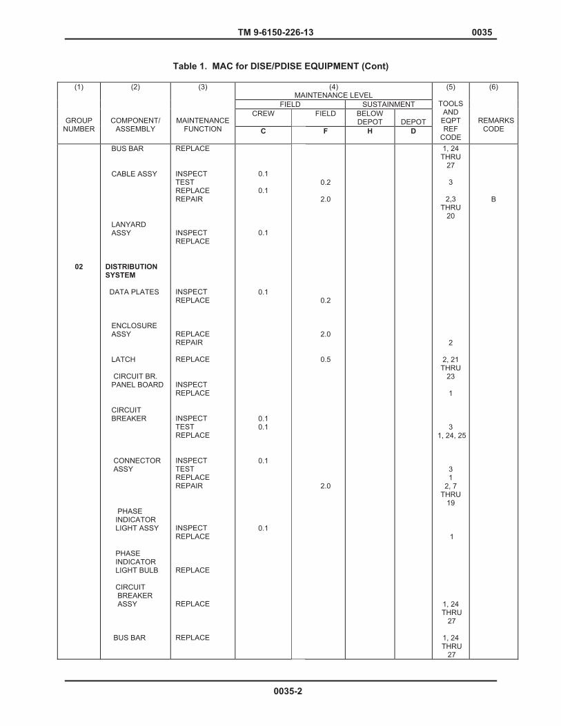
TM 9-6150-226-13 0035
Table 1. MAC for DISE/PDISE EQUIPMENT (Cont)
(4) MAINTENANCE LEVEL
FIELD SUSTAINMENT CREW FIELD BELOW
DEPOT
DEPOT
(1)
GROUP NUMBER
(2)
COMPONENT/ ASSEMBLY
(3)
MAINTENANCE FUNCTION C
F
H
D
(5)
TOOLS AND
EQPT REF
CODE
(6)
REMARKSCODE
02
BUS BAR CABLE ASSY LANYARD ASSY DISTRIBUTION SYSTEM DATA PLATES ENCLOSURE ASSY LATCH
CIRCUIT BR. PANEL BOARD CIRCUIT BREAKER CONNECTOR ASSY PHASE INDICATOR LIGHT ASSY PHASE INDICATOR LIGHT BULB CIRCUIT BREAKER ASSY BUS BAR
REPLACE INSPECT TEST REPLACE REPAIR INSPECT REPLACE INSPECT REPLACE REPLACE REPAIR REPLACE INSPECT REPLACE INSPECT TEST REPLACE INSPECT TEST REPLACE REPAIR INSPECT REPLACE REPLACE REPLACE REPLACE
0.1
0.1
0.1
0.1
0.1 0.1
0.1
0.1
0.2
2.0
0.2
2.0
0.5
2.0
1, 24 THRU
27
3
2,3 THRU
20 2
2, 21 THRU
23
1
3 1, 24, 25
3 1
2, 7 THRU
19
1
1, 24 THRU
27
1, 24 THRU
27
B
0035-2

TM 9-6150-226-13 0035
Table 1. MAC for DISE/PDISE EQUIPMENT (Cont)
(4) MAINTENANCE LEVEL
FIELD SUSTAINMENT CREW FIELD BELOW
DEPOT
DEPOT
(1)
GROUP NUMBER
(2)
COMPONENT/ ASSEMBLY
(3)
MAINTENANCE FUNCTION C
F
H
D
(5)
TOOLS AND
EQPT REF
CODE
(6)
REMARKSCODE
03
CABLE ASSY DUPLEX RECEPTACLE GROUP CONTAINER, TRANSIT AND STORAGE CONNECTOR ASSY UTILITY ASSEMBLY, ELECTRICAL CABLE ASSY
BRANCH CIRCUIT CABLE ASSY BRANCH CIRCUIT TRUNK ASSY RECEPTACLE GROUP DATA PLATES UTILITY LIGHT ASSEMBLY, INCANDESCENT, DUAL BULB
INSPECT TEST REPLACE REPAIR INSPECT TEST REPLACE REPAIR INSPECT REPLACE REPAIR INSPECT TEST REPLACE REPAIR INSPECT TEST REPLACE REPAIR INSPECT TEST REPLACE REPAIR INSPECT TEST REPLACE REPAIR INSPECT REPLACE INSPECT TEST REPLACE REPAIR
0.1
0.1
0.1
0.1
0.1
0.1
0.1
0.1
0.1
0.1
0.1
0.1
0.1
0.1
0.1
0.1
1.0 1.0
1.0
2.0
0.2
3
2, 3 THRU
20 3
1, 2, 12
1, 12
3
2, 12
3
2, 12
3
2, 12
3
1, 2, 12
3
1
B
B
0035-3
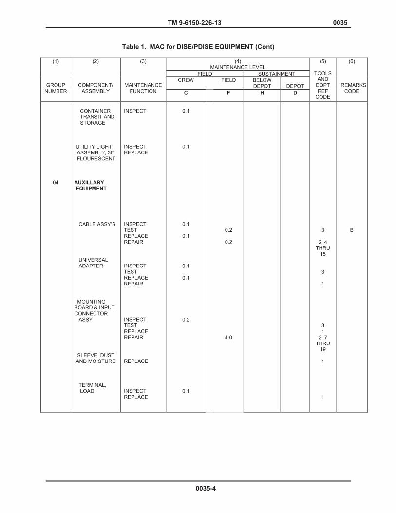
TM 9-6150-226-13 0035
Table 1. MAC for DISE/PDISE EQUIPMENT (Cont)
(4) MAINTENANCE LEVEL
FIELD SUSTAINMENT CREW FIELD BELOW
DEPOT
DEPOT
(1)
GROUP NUMBER
(2)
COMPONENT/ ASSEMBLY
(3)
MAINTENANCE FUNCTION C
F
H
D
(5)
TOOLS AND
EQPT REF
CODE
(6)
REMARKSCODE
04
CONTAINER TRANSIT AND STORAGE UTILITY LIGHT ASSEMBLY, 36’ FLOURESCENT
AUXILLARY EQUIPMENT CABLE ASSY’S UNIVERSAL ADAPTER MOUNTING BOARD & INPUT CONNECTOR ASSY SLEEVE, DUST AND MOISTURE TERMINAL, LOAD
INSPECT INSPECT REPLACE INSPECT TEST REPLACE REPAIR INSPECT TEST REPLACE REPAIR INSPECT TEST REPLACE REPAIR REPLACE INSPECT REPLACE
0.1
0.1
0.1
0.1
0.1
0.1
0.2
0.1
0.2
0.2
4.0
3
2, 4 THRU
15
3
1
3 1
2, 7 THRU
19
1
1
B
0035-4

TM 9-6150-226-13 0035
Table 2. Tool and Test Equipment Requirements
TOOL OR TEST EQUIPMENT REF CODE
MAINTENANCE CATEGORY
NOMENCLATURE
NATIONAL/ NATO STOCK NUMBER
TOOL NUMBERS
1
2
3
4
5
6
7
8
9
10
11
12
13
14
15
16
17
18
19
20
21
22
23
24
25
26
27
0 0 0 F F F
F
F F
F F
F
F
F
F
F F
F
F
F F F F O O O O
TOOL KIT, GENERAL MECHANICS AUTOMOTIVE SHOP EQUIP., AUTIO, ORG # 2 COMMON SHOP EQUIP., AUTIO, ORG # 1 COMMON SHOP EQUIPMENT AUTOMOTIVE MAINTENANCE SHOP EQUIPMENT, MECH. MAINTENANCE SHELTER TOOL KIT, RIVETER TOOL REMOVER, SIZE 4/0 TOOL REMOVER, SIZE 20 TOOL REMOVER, SIZE 10 TOOL REMOVER, SIZE # 4 TOOL REMOVER, SIZE # 6 TOOL INSTALLER SIZE # 12 TOOL REMOVER, SIZE # 12 TOOL KIT CRIMPING TOOL, CRIMPING TOOL STRIPPER CABLE TOOL STRIPPER WIRE TOOL STRIPPER CABLE TOOL REMOVER, SIZE # 2 STRIPPER, CABLE, HAND ADJUSTABLE DRILL, ELECT, PORTABLE 8845 OR EQUIVALENT DRILL, BIT NO. 13 RIVETER, BLIND HEAD G749 OR EQUIVALENT WRENCH, TORQUE 6063 OR EQUIVALENT SCREWDRIVER, 3/8 X 12 FLAT ATTACHMENT, SOCKET HEAD WRENCH, 3/8 DRIVE x 5/16 ATTACHMENT, SCREWDRIVER TIP, 3/8 DRIVE
5180-00-177-7033 4910-00-754-0050 4910-00-754-0654 4910-00-754-0705 4940-00209-6227 5120-00017-2849 81349 81349 81349 81349 81349 81349 81349 81349 59703 30119 59730 30119 81349 5130-00-226-5586 5130-01-046-2902 5120-00-148-5847 5120-00-177-7328 5120-00-243-7337 5120-01-016-8713 5120-00-243-7337
SC5180-90-CL-N26 SC4910-95-CL-A72 SC4910-95-CL-A74 SC4910-95-CL-A31 SC4910-95-CL-A52 J-T49CMR M81969/27-01 M81969/27-02 M81969/27-03 M81969/27-05 M81969/27-06 M81969/8-09 M81969/8-10 M83507/11-1 WT1111M 45-156 WT2000 45-127 M81969/27-04 45-156 8845 G649 6063
0035-5

TM 9-6150-226-13 0035
Table 3. REMARKS
REFERENCE CODE REMARKS
A Repair of enclosure consist of welding and straightening B Fabrication of DISE/PDISE cable assemblies is authorized at the Field maintenance level. C Solder dip or solder gun wire ends not to exceed 0.025 inch using
Kester Solder, MIL Spec No. QQ-S-571 (Sn 60, Pb 40). END OF WORK PACKAGE
0035-6
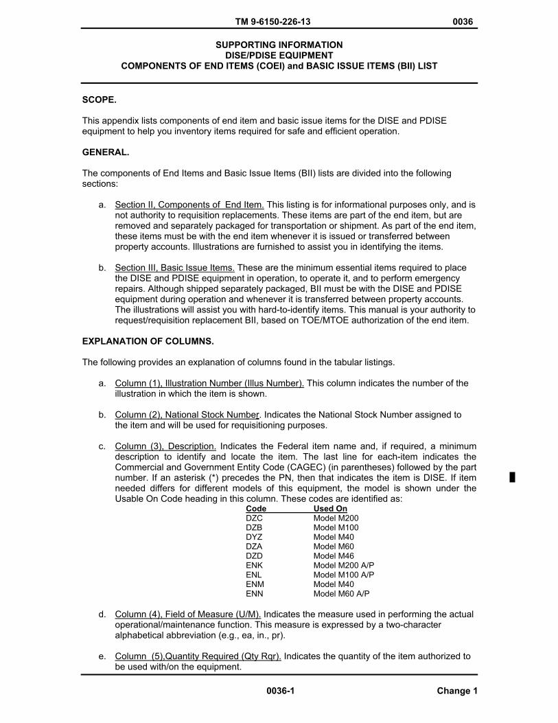
TM 9-6150-226-13 0036
SUPPORTING INFORMATION DISE/PDISE EQUIPMENT
COMPONENTS OF END ITEMS (COEI) and BASIC ISSUE ITEMS (BII) LIST
SCOPE.
This appendix lists components of end item and basic issue items for the DISE and PDISE equipment to help you inventory items required for safe and efficient operation.
GENERAL.
The components of End Items and Basic Issue Items (BII) lists are divided into the following sections:
a. Section II, Components of End Item. This listing is for informational purposes only, and is not authority to requisition replacements. These items are part of the end item, but are removed and separately packaged for transportation or shipment. As part of the end item, these items must be with the end item whenever it is issued or transferred between property accounts. Illustrations are furnished to assist you in identifying the items.
b. Section III, Basic Issue Items. These are the minimum essential items required to place the DISE and PDISE equipment in operation, to operate it, and to perform emergency repairs. Although shipped separately packaged, BII must be with the DISE and PDISE equipment during operation and whenever it is transferred between property accounts. The illustrations will assist you with hard-to-identify items. This manual is your authority to request/requisition replacement BII, based on TOE/MTOE authorization of the end item.
EXPLANATION OF COLUMNS.
The following provides an explanation of columns found in the tabular listings.
a. Column (1), Illustration Number (Illus Number). This column indicates the number of the illustration in which the item is shown.
b. Column (2), National Stock Number. Indicates the National Stock Number assigned to the item and will be used for requisitioning purposes.
c. Column (3), Description. Indicates the Federal item name and, if required, a minimum description to identify and locate the item. The last line for each-item indicates the Commercial and Government Entity Code (CAGEC) (in parentheses) followed by the part number. If an asterisk (*) precedes the PN, then that indicates the item is DISE. If item needed differs for different models of this equipment, the model is shown under the Usable On Code heading in this column. These codes are identified as:
Code Used OnDZC Model M200 DZB Model M100DYZ Model M40DZA Model M60DZD Model M46ENK Model M200 A/P ENL Model M100 A/P ENM Model M40ENN Model M60 A/P
d. Column (4), Field of Measure (U/M). Indicates the measure used in performing the actual operational/maintenance function. This measure is expressed by a two-character alphabetical abbreviation (e.g., ea, in., pr).
e. Column (5),Quantity Required (Qty Rqr). Indicates the quantity of the item authorized to be used with/on the equipment.
0036-1 Change 1
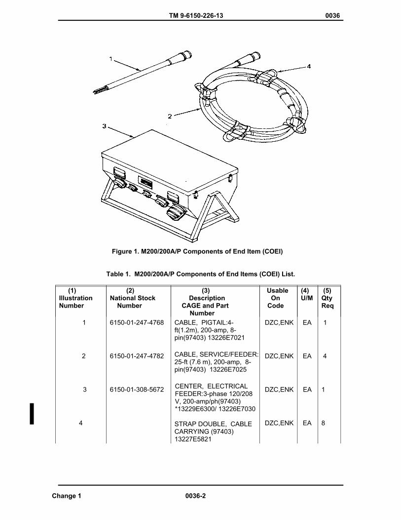
TM 9-6150-226-13 0036
Figure 1. M200/200A/P Components of End Item (COEI)
Table 1. M200/200A/P Components of End Items (COEI) List.
(1) IllustrationNumber
(2) National Stock Number
(3) Description CAGE and Part
Number
Usable OnCode
(4)U/M
(5) Qty Req
1
2
3
4
6150-01-247-4768
6150-01-247-4782
6150-01-308-5672
CABLE, PlGTAlL:4-ft(1.2m), 200-amp, 8-pin(97403) 13226E7021
CABLE, SERVICE/FEEDER:25-ft (7.6 m), 200-amp, 8-pin(97403) 13226E7025
CENTER, ELECTRICAL FEEDER:3-phase 120/208 V, 200-amp/ph(97403) *13229E6300/ 13226E7030
STRAP DOUBLE, CABLECARRYING (97403) 13227E5821
DZC,ENK
DZC,ENK
DZC,ENK
DZC,ENK
EA
EA
EA
EA
1
4
1
8
Change 1 0036-2
TM 9-6150-226-13 0036
Figure 2. M100/100A/P Components of End Item (COEI) List.
Table 2. M100/100A/P Components of End Item (COEI) List.
(1) IllustrationNumber
(2) National Stock Number
(3) Description CAGE and Part
Number
Usable OnCode
(4)U/M
(5) Qty Req
5
6
7
8
6150-01-256-6300
6150-01-256-6304
6150-01-256-6299
(See Figure 2)
CABLE, PIGTAIL 4-ft (1.2m), 100-amp, 8-pin (97403) 13226E7020
CABLE, SERVICE/FEEDER:50-ft (15.2 m), 100-amp, 8-pin (97403) 13226E7024
CENTER, ELECTRICAL FEEDER: 3-phase 120/208 U, 100-amp/ph(97403) 133229E6325/ *13226E7029
STRAP SINGLE, CABLECARRYING (97403) 13227E5825
DZB,ENL
DZB,ENL
DZB,ENL
DZB,ENL
EA
EA
EA
EA
1
2
1
8
0036-3 Change 1

TM 9-6150-226-13 0036
Figure 3. M40/M40A/P Components of End Item (COEI) List.
Table 3. M40/M40A/P Components of End Item (COEI) List. (1)IllustrationNumber
(2) National Stock Number
(3) Description CAGE and Part
Number
Usable OnCode
(4)U/M
(5) Qty Req
9
10
11
12
6150-01-251-9125
6150-01-250-0044
6150-01-250-3643
6150-01-253-4290
(See Figure 3)
BOX, DUPLEX RECEPTACLE: 120 V, 20-amp (97403) 13226E7040
CABLE, EXTENSION: 25ft (7.6m), 20-amp, 3-pin (97403) 13226E7032-2
CABLE, EXTENSION: 50-ft (15.2m), 20-amp, 3-pin (97403) 13226E7032-1
CABLE, LIGHT SET, 25 OUTLET 13228E3355
DYZ, ENM
DYZ, ENM
DYZ, ENM
DYZ, ENM
EA
EA
EA
EA
1
3
3
2
Change 1 0036-4
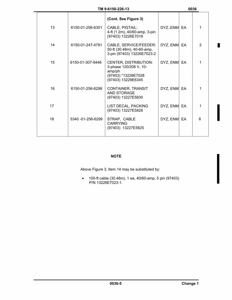
TM 9-6150-226-13 0036
13
14
15
16
17
18
6150-01-256-6301
6150-01-247-4781
6150-01-307-9446
6150-01-256-6298
5340 -01-256-6299
(Cont. See Figure 3)
CABLE, PIGTAIL: 4-ft (1.2m), 40/60-amp, 3-pin (97403) 13226E7019
CABLE, SERVICE/FEEDER: 50-ft (30.48m), 40-60-amp, 3-pin (97403) 13226E7023-2
CENTER, DISTRIBUTION: 3-phase 120/208 V, 10-amp/ph(97403) *13226E7028 (97403) 13229E6345
CONTAINER, TRANSIT AND STORAGE (97403) 13227E5830
LIST DECAL, PACKING (97403) 13227E5826
STRAP, CABLECARRYING (97403) 13227E5825
DYZ.,ENM
DYZ, ENM
DYZ, ENM
DYZ, ENM
DYZ, ENM
DYZ, ENM
EA
EA
EA
EA
EA
EA
1
2
1
1
1
8
NOTE
Above Figure 3, Item 14 may be substituted by:
� 100-ft cable (30.48m), 1 ea, 40/60-amp, 5 pin (97403) P/N 13226E7023-1.
0036-5 Change 1
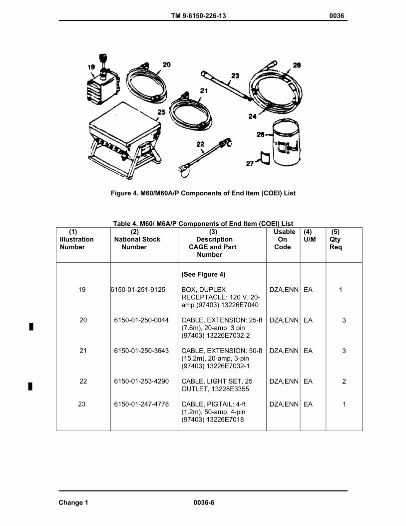
TM 9-6150-226-13 0036
Figure 4. M60/M60A/P Components of End Item (COEI) List
Table 4. M60/ M6A/P Components of End Item (COEI) List (1) IllustrationNumber
(2) National Stock Number
(3) Description CAGE and Part
Number
Usable OnCode
(4)U/M
(5) Qty Req
19
20
21
22
23
6150-01-251-9125
6150-01-250-0044
6150-01-250-3643
6150-01-253-4290
6150-01-247-4778
(See Figure 4)
BOX, DUPLEX RECEPTACLE: 120 V, 20-amp (97403) 13226E7040
CABLE, EXTENSION: 25-ft (7.6m), 20-amp, 3 pin (97403) 13226E7032-2
CABLE, EXTENSION: 50-ft (15.2m), 20-amp, 3-pin (97403) 13226E7032-1
CABLE, LIGHT SET, 25 OUTLET, 13228E3355
CABLE, PIGTAIL: 4-ft (1.2m), 50-amp, 4-pin(97403) 13226E7018
DZA,ENN
DZA,ENN
DZA,ENN
DZA,ENN
DZA,ENN
EA
EA
EA
EA
EA
1
3
3
2
1
Change 1 0036-6
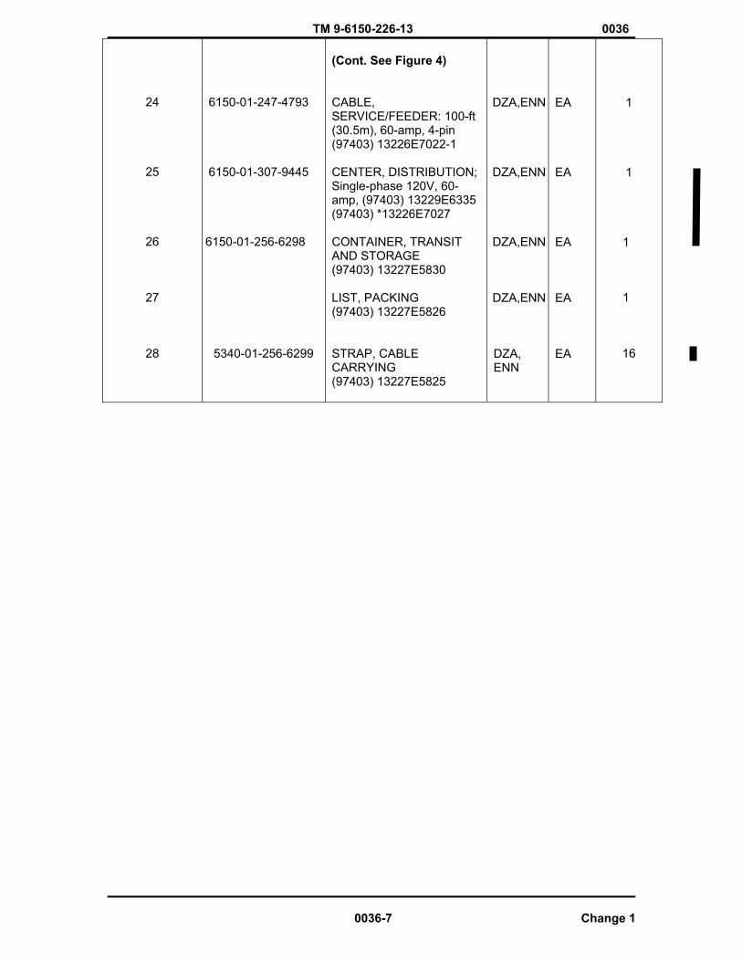
TM 9-6150-226-13 0036
24
25
26
27
28
6150-01-247-4793
6150-01-307-9445
6150-01-256-6298
5340-01-256-6299
(Cont. See Figure 4)
CABLE,SERVICE/FEEDER: 100-ft (30.5m), 60-amp, 4-pin (97403) 13226E7022-1
CENTER, DISTRIBUTION; Single-phase 120V, 60-amp, (97403) 13229E6335 (97403) *13226E7027
CONTAINER, TRANSIT AND STORAGE (97403) 13227E5830
LIST, PACKING (97403) 13227E5826
STRAP, CABLE CARRYING (97403) 13227E5825
DZA,ENN
DZA,ENN
DZA,ENN
DZA,ENN
DZA,ENN
EA
EA
EA
EA
EA
1
1
1
1
16
0036-7 Change 1
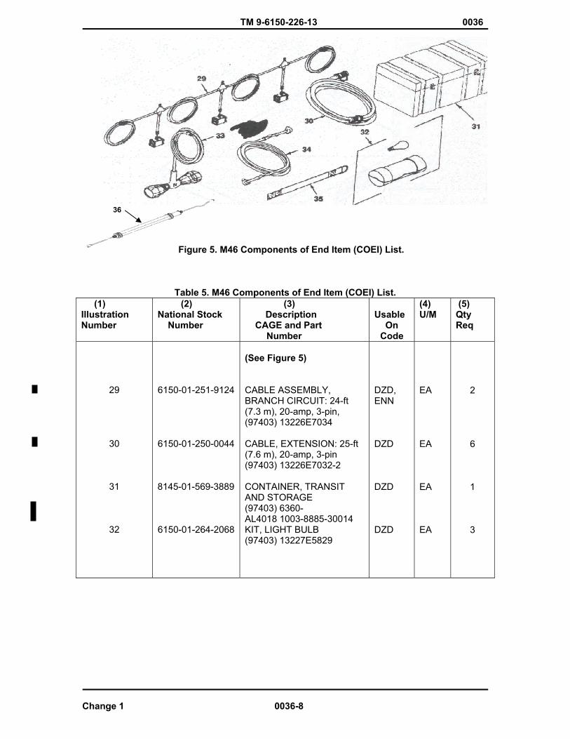
TM 9-6150-226-13 0036
36
Figure 5. M46 Components of End Item (COEI) List.
Table 5. M46 Components of End Item (COEI) List. (1) IllustrationNumber
(2) National Stock Number
(3) Description CAGE and Part
Number
Usable OnCode
(4)U/M
(5) Qty Req
29
30
31
32
6150-01-251-9124
6150-01-250-0044
8145-01-569-3889
6150-01-264-2068
(See Figure 5)
CABLE ASSEMBLY, BRANCH CIRCUIT: 24-ft (7.3 m), 20-amp, 3-pin, (97403) 13226E7034
CABLE, EXTENSION: 25-ft (7.6 m), 20-amp, 3-pin (97403) 13226E7032-2
CONTAINER, TRANSIT AND STORAGE (97403) 6360- AL4018 1003-8885-30014 KIT, LIGHT BULB (97403) 13227E5829
DZD,ENN
DZD
DZD
DZD
EA
EA
EA
EA
2
6
1
3
Change 1 0036-8
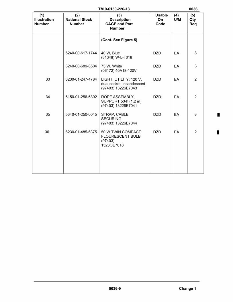
TM 9-6150-226-13 0036 (1) IllustrationNumber
(2) National Stock Number
(3) Description CAGE and Part
Number
Usable OnCode
(4)U/M
(5) Qty Req
33
34
35
36
6240-00-617-1744
6240-00-689-8504
6230-01-247-4784
6150-01-256-6302
5340-01-250-0045
6230-01-485-6375
(Cont. See Figure 5)
40 W, Blue (81348) W-L-I 018
75 W, White (06172) 40A18-120V
LIGHT, UTILITY: 120 V, dual socket, incandescent (97403) 13226E7043
ROPE ASSEMBLY, SUPPORT 53-h (1.2 m) (97403) 13226E7041
STRAP, CABLE SECURING(97403) 13226E7044
50 W TWIN COMPACT FLOURESCENT BULB (97403) 1323OE7018
DZD
DZD
DZD
DZD
DZD
DZD
EA
EA
EA
EA
EA
EA
3
3
2
2
8
2
0036-9 Change 1
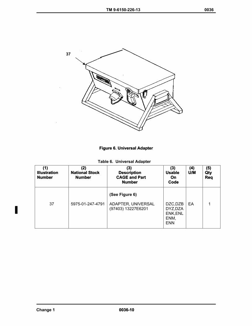
TM 9-6150-226-13 0036
37
Figure 6. Universal Adapter Figure 6. Universal Adapter
Table 6. Universal Adapter (1) (1) IllustrationIllustrationNumber Number
(2) (2) National Stock National Stock Number Number
(3) (3) Description Description CAGE and Part CAGE and Part Number Number
(3) (3) Usable Usable
OnCode OnCode
(4) (4) U/M U/M
(5) (5) Qty Qty Req Req
37 5975-01-247-4791
(See Figure 6)
ADAPTER, UNIVERSAL (97403) 13227E6201
DZC,DZBDYZ,DZAENK,ENLENM,ENN
EA 1
Change 1 0036-10 0036-10

TM 9-6150-226-13 0036
BASIC ISSUE ITEMS (BII)
The only BII item authorized is TM 11-6150-226-13, Operator and Field Maintenance Manual for Distribution Illumination Systems, Electrical (DISE) and Power Distribution Illumination Systems.
END OF WORK PACKAGE
0036-11/12 Blank Change 1


TM 9-6150-226-13 0037
SUPPORTING INFORMATION DISE/PDISE EQUIPMENT
ADDITIONAL AUTHORIZATION LIST (AAL) ITEMS
There are no Additional Authorized Items (AAL) for DISE/PDISE equipment at this time.
END OF WORK PACKAGE
0037-1/2 Blank

TM 9-6150-226-13 0038
SUPPORTING INFORMATION DISE/PDISE EQUIPMENT
EXPENDABLE/DURABLE SUPPLIES AND MATERIALS LIST
SCOPE
This appendix lists expendable supplies and materials you will need to operate and maintain the DISE and PDISE systems. This listing is for informational purposes only and is not authority to requisition the listed items. These items are authorized to you by CTA 50-970, Expendable/Durable Items (Except Medical, Class V, Repair Parts, and Heraldic Items), or CTA 8-100, Army Medical Department Expendable/Durable Items. EXPLANATION OF COLUMNS.
a. Column (1) - Item Number. This number is assigned to the entry in the listing and is referenced in the narrative instructions to identify the material (e.g., Use dry cleaning solvent, item 1, app E).
b. CoIumn (2) - Level. This column identifies the lowest level of maintenance that would most likely require the listed item.
O – Service Level Maintenance
F – Field Level Maintenance
c. Column (3)-National Stock Number. This is the national stock number assigned to the item; use
it to request or requisition the item.
d. CoIumn (4) - Description. Indicates the Federal item name and, if required, a description to identify the item. The last line for each item indicates the Commercial and Government Entity Code (CAGEC) in parentheses, followed by the part number.
e. Column (5) - Field of Measure (U/M) Indicates the measure used in performing the actual
maintenance function. This measure is expressed by a two-character alphabetical abbreviation (e.g., ea, in., pr). If the field of measure differs from the field of issue, requisition the lowest field of issue that will satisfy your requirements.
0038-1

Verified Draft
TM 9-6150-226-13 0038
Table 1. Expendable/Durable Supplies and Materials List
END OF WORK PACKAGE
0038-2
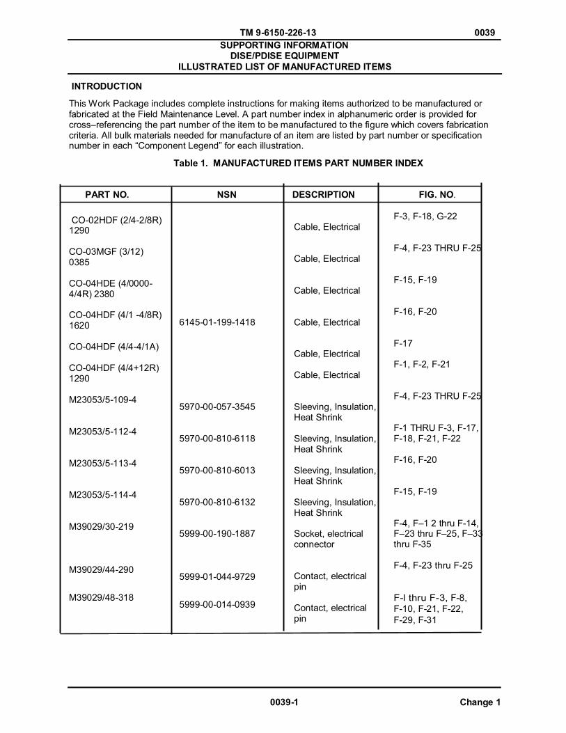
TM 9-6150-226-13 0039
0039-1 Change 1
SUPPORTING INFORMATION DISE/PDISE EQUIPMENT
ILLUSTRATED LIST OF MANUFACTURED ITEMS
INTRODUCTION
This Work Package includes complete instructions for making items authorized to be manufactured or fabricated at the Field Maintenance Level. A part number index in alphanumeric order is provided for cross–referencing the part number of the item to be manufactured to the figure which covers fabrication criteria. All bulk materials needed for manufacture of an item are listed by part number or specification number in each “Component Legend” for each illustration.
Table 1. MANUFACTURED ITEMS PART NUMBER INDEX PART NO.
NSN
DESCRIPTION
FIG. NO. CO-02HDF (2/4-2/8R) 1290 CO-03MGF (3/12) 0385 CO-04HDE (4/0000- 4/4R) 2380 CO-04HDF (4/1 -4/8R) 1620 CO-04HDF (4/4-4/1A) CO-04HDF (4/4+12R) 1290 M23053/5-109-4 M23053/5-112-4 M23053/5-113-4 M23053/5-114-4 M39029/30-219 M39029/44-290 M39029/48-318
6145-01-199-1418 5970-00-057-3545 5970-00-810-6118 5970-00-810-6013 5970-00-810-6132 5999-00-190-1887 5999-01-044-9729
5999-00-014-0939
Cable, Electrical Cable, Electrical Cable, Electrical Cable, Electrical Cable, Electrical Cable, Electrical Sleeving, Insulation, Heat Shrink Sleeving, Insulation, Heat Shrink Sleeving, Insulation, Heat Shrink Sleeving, Insulation, Heat Shrink Socket, electrical connector Contact, electrical pin Contact, electrical pin
F-3, F-18, G-22 F-4, F-23 THRU F-25 F-15, F-19 F-16, F-20 F-17 F-1, F-2, F-21 F-4, F-23 THRU F-25 F-1 THRU F-3, F-17, F-18, F-21, F-22 F-16, F-20 F-15, F-19 F-4, F–1 2 thru F-14, F–23 thru F–25, F–33 thru F-35 F-4, F-23 thru F-25 F-l thru F-3, F-8, F-10, F-21, F-22, F-29, F-31

TM 9-6150-226-13 0039
Change 1 0039-2
PART NO. NSN DESCRIPTION FIGURE NO. M39029/48-319 M39029/48-320 M39029/48-321 M39029/48-322 M39029/48-323 M39029/48-324 M39029/48-327 M39029/48-328 M39029/49-329 M39029/49-330 M39029/49-331 M39029/49-332 M39029/49-333 M39029/49-335 M5086/2-1-9 M5086/2-12-9
5999-01-108-8602 5999-01-014-0941 5999-01-014-0943 5999-00-344-1907 5999-01-130-1899 5999-01-113-4552 5999-00-344-1904 5999-00-344-1906 5999-00-014-0952 5999-01-131-5888 5999-01-191-3187 5999-00-346-8787 5999-00-346-1897 5999-00-344-1909 6145-01-197-3918 6145-00-578-7514
Contact, electrical Pin Contact, electrical Pin Contact, electrical Pin Contact, electrical Pin Contact, electrical Pin Contact, electrical Pin Contact, electrical Pin Contact, electrical Pin Contact, electrical Pin Contact, electrical Pin Contact, electrical Pin Contact, electrical Pin Contact, electrical Pin Contact, electrical Pin Wire, electrical Wire, electrical
F-6, F-20, F-27 F-1 THRU F-3, F-8, F-10, F-21, F-22, F-29 F-31 F-1 THRU F-3, F-8, F-10, F-21, F-22, F-29 F-31 F-5, F-19, F-26 F-6, F-27 F-6, F-27 F-5, F-19, F-26 F-5, F-19, F-26 F-3, F-9, F-11, F-17, F-18, F-21, F-22, F-30, F-32 F-7, F-16, F-20, F-28 F-1 THRU F-3, F-9, F-11, F-18, F-21, F-22 F-30, F-32 F-15-F-19 F-7, F-16, F-20, F-28 F-15, F-19 F-6, F-7, F-27, F-28 F-12, THRU F-14, F-33 TRU F-35

TM 9-6150-226-13 0039
PART NO.
M5086/2-2/0-9 M5086/2-4/0-9 M5086/2-4-9 M5086/2-6-9 M5086/2-8-9 M39029/49-331 MS25042-16D MS25043-16D MS3102R16-10S MS3348-6-8L MS3349-410-210 MS3451W16-10S MS3452W16-10S MS2346W16-10P MS90555C32405S MS90555C32413S MS90555C44413S MS90556C32405P MS90556C32413P
NSN 6145-00-578-6600 6145-00-578-6595 6145-00-578-6594 6145-00-284-0657 5999-01-091-3187 5935-01-189-3220 5935-01-160-7188 5935-01-160-1788 5999-01-167-0838 5990-01-217-4773 5935-01-260-9595 5935-01-160-1788 5935-01-026-2177 5935-01-087-0201 5935-01-092-3451 5935-01-086-6421
DESCRIPTION Wire, electrical Wire, electrical Wire, electrical Wire, electrical Wire, electrical Contact, electrical Socket Cover, electrical Connector, straight plug Cover, electrical, Connector Connector, electrical Receptacle Reducer, connector pin Reducer, contact Electrical Connector, electrical Receptacle Connector, electrical Receptacle Connector, electrical Straight plug Connector, electrical Receptacle Connector, electrical Receptacle Connector, electrical Straight plug Connector, electrical Straight plug Connector, electrical Straight plug
FIGURE NO. F-5 F-26 F-8 THRU F-11, F-29 THRU F-32 F-29 THRU F-32 F-8 THRU F-11 F-18 F-4, F-23 THRU F-25 F-4, F-12 THRU F-14 F-23 THRU F-25, F-33 TRHU F-35 F-18 F-1 THRU F-3 F-7 THRU F-11 F-16, F-18, F20 THRU F-25, F28 THRU F-32 F-5, F-26 F-4, F-23 THRU F-25 F-12 THRU F-14 F33 THRU F-35 F-4, F-23 THRU F-25 F-11, F-32 F-9, F-30 F-7, F-28 F-3, F-22 F-1, F-2, F-21
0039-3 Change 1
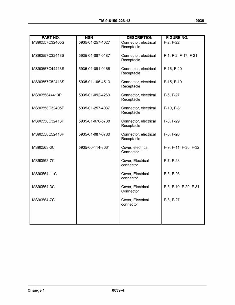
TM 9-6150-226-13 0039
Change 1 0039-4
PART NO. NSN DESCRIPTION FIGURE NO. MS90557C32405S MS90557C32413S MS90557C44413S MS90557C52413S MS9055844413P MS90558C32405P MS90558C32413P MS90558C52413P MS90563-3C MS90563-7C MS90564-11C MS90564-3C MS90564-7C
5935-01-257-4027 5935-01-087-0187 5935-01-091-9166 5935-01-106-4513 5935-01-092-4269 5935-01-257-4037 5935-01-076-5738 5935-01-087-0780 5935-00-114-8061
Connector, electrical Receptacle Connector, electrical Receptacle Connector, electrical Receptacle Connector, electrical Receptacle Connector, electrical Receptacle Connector, electrical Receptacle Connector, electrical Receptacle Connector, electrical Receptacle Cover, electrical Connector Cover, Electrical connector Cover, Electrical connector Cover, Electrical Connector Cover, Electrical connector
F-2, F-22 F-1, F-2, F-17, F-21 F-16, F-20 F-15, F-19 F-6, F-27 F-10, F-31 F-8, F-29 F-5, F-26 F-9, F-11, F-30, F-32 F-7, F-28 F-5, F-26 F-8, F-10, F-29, F-31 F-6, F-27
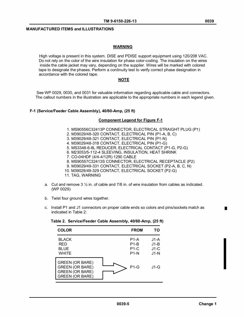
TM 9-6150-226-13 0039
0039-5 Change 1
MANUFACTURED ITEMS and ILLUSTRATIONS
WARNING
High voltage is present in this system. DISE and PDISE support equipment using 120/208 VAC. Do not rely on the color of the wire insulation for phase color-coding. The insulation on the wires inside the cable jacket may vary, depending on the supplier. Wires will be marked with colored tape to designate the phases. Perform a continuity test to verify correct phase designation in accordance with the colored tape.
See WP 0029, 0030, and 0031 for valuable information regarding applicable cable and connectors. The callout numbers in the illustration are applicable to the appropriate numbers in each legend given.
F-1 (Service/Feeder Cable Assembly), 40/60-Amp, (25 ft)
Component Legend for Figure F-1
1. MS90556C32413P CONNECTOR, ELECTRICAL STRAIGHT PLUG (P1) 2. M39029/48-320 CONTACT, ELECTRICAL PIN (P1-A, B, C) 3. M39029/48-321 CONTACT, ELECTRICAL PIN (P1-N) 4. M39029/48-318 CONTACT, ELECTRICAL PIN (P1-G) 5. MS3348-6-8L REDUCER, ELECTRICAL CONTACT (P1-G, P2-G) 6. M23053/5-112-4 SLEEVING, INSULATION, HEAT SHRINK 7. CO-04HDF (4/4-4/12R) 1290 CABLE 8. MS90557C32413S CONNECTOR, ELECTRICAL RECEPTACLE (P2) 9. M39029/49-331 CONTACT, ELECTRICAL SOCKET (P2-A, B, C, N)
10. M39029/49-329 CONTACT, ELECTRICAL SOCKET (P2-G) 11. TAG, WARNING
a. Cut and remove 3 ½ in. of cable and 7/8 in. of wire insulation from cables as indicated. (WP 0029)
b. Twist four ground wires together. c. Install P1 and J1 connectors on proper cable ends so colors and pins/sockets match as indicated in Table 2:
Table 2. Service/Feeder Cable Assembly, 40/60-Amp, (25 ft) COLOR FROM TO BLACK P1-A J1-A RED P1-B J1-B BLUE P1-C J1-C WHITE P1-N J1-N GREEN (OR BARE) GREEN (OR BARE) P1-G J1-G GREEN (OR BARE) GREEN (OR BARE)
NOTE
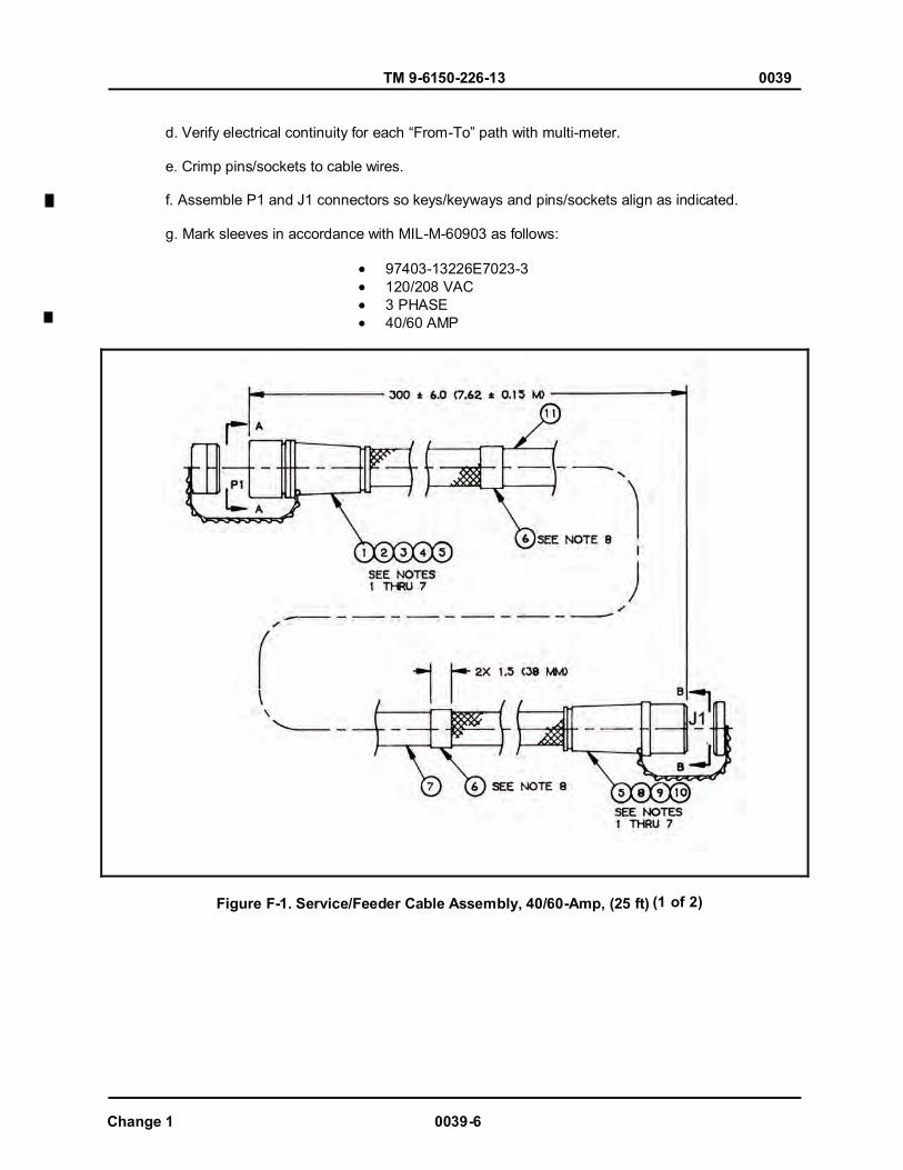
TM 9-6150-226-13 0039
Change 1 0039-6
d. Verify electrical continuity for each “From-To” path with multi-meter. e. Crimp pins/sockets to cable wires. f. Assemble P1 and J1 connectors so keys/keyways and pins/sockets align as indicated. g. Mark sleeves in accordance with MIL-M-60903 as follows:
97403-13226E7023-3 120/208 VAC 3 PHASE 40/60 AMP
Figure F-1. Service/Feeder Cable Assembly, 40/60-Amp, (25 ft) (1 of 2)
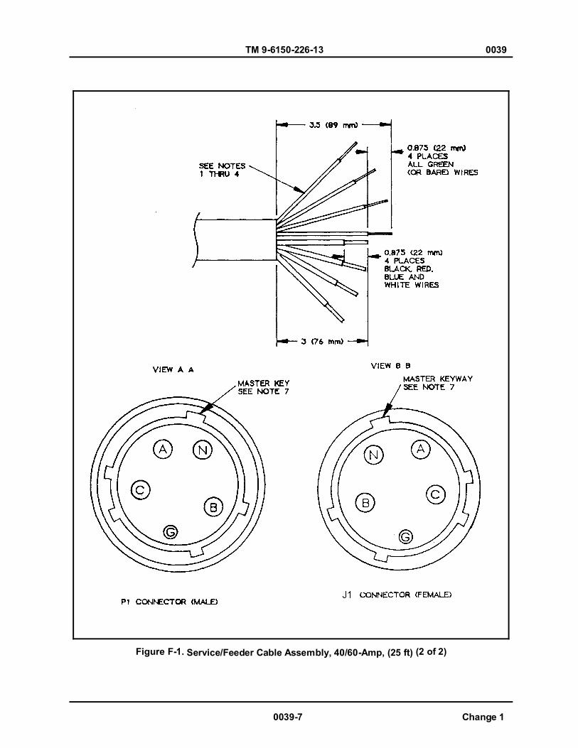
TM 9-6150-226-13 0039
0039-7 Change 1
Figure F-1. Service/Feeder Cable Assembly, 40/60-Amp, (25 ft) (2 of 2)
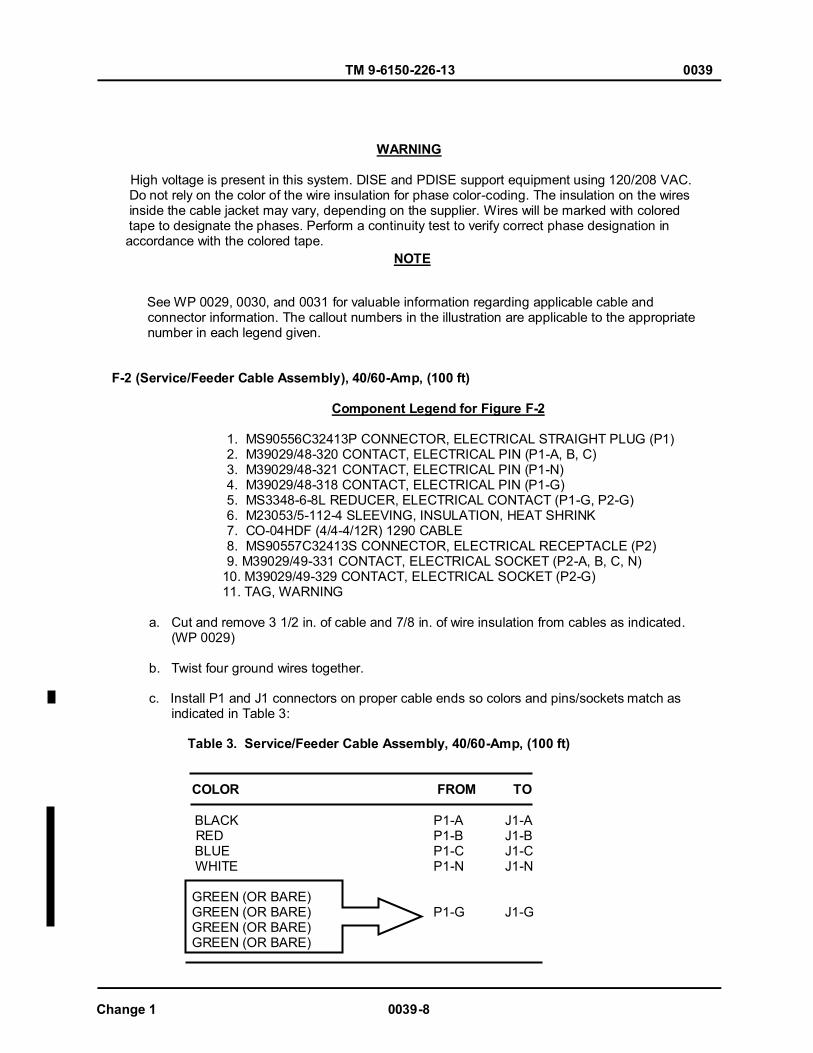
TM 9-6150-226-13 0039
Change 1 0039-8
WARNING
High voltage is present in this system. DISE and PDISE support equipment using 120/208 VAC. Do not rely on the color of the wire insulation for phase color-coding. The insulation on the wires inside the cable jacket may vary, depending on the supplier. Wires will be marked with colored tape to designate the phases. Perform a continuity test to verify correct phase designation in accordance with the colored tape.
See WP 0029, 0030, and 0031 for valuable information regarding applicable cable and connector information. The callout numbers in the illustration are applicable to the appropriate number in each legend given.
F-2 (Service/Feeder Cable Assembly), 40/60-Amp, (100 ft) Component Legend for Figure F-2
1. MS90556C32413P CONNECTOR, ELECTRICAL STRAIGHT PLUG (P1) 2. M39029/48-320 CONTACT, ELECTRICAL PIN (P1-A, B, C) 3. M39029/48-321 CONTACT, ELECTRICAL PIN (P1-N) 4. M39029/48-318 CONTACT, ELECTRICAL PIN (P1-G) 5. MS3348-6-8L REDUCER, ELECTRICAL CONTACT (P1-G, P2-G) 6. M23053/5-112-4 SLEEVING, INSULATION, HEAT SHRINK 7. CO-04HDF (4/4-4/12R) 1290 CABLE 8. MS90557C32413S CONNECTOR, ELECTRICAL RECEPTACLE (P2) 9. M39029/49-331 CONTACT, ELECTRICAL SOCKET (P2-A, B, C, N)
10. M39029/49-329 CONTACT, ELECTRICAL SOCKET (P2-G)11. TAG, WARNING
a. Cut and remove 3 1/2 in. of cable and 7/8 in. of wire insulation from cables as indicated. (WP 0029)
b. Twist four ground wires together. c. Install P1 and J1 connectors on proper cable ends so colors and pins/sockets match as indicated in Table 3:
Table 3. Service/Feeder Cable Assembly, 40/60-Amp, (100 ft)
COLOR FROM TO BLACK P1-A J1-A RED P1-B J1-B BLUE P1-C J1-C WHITE P1-N J1-N GREEN (OR BARE) GREEN (OR BARE) P1-G J1-G GREEN (OR BARE) GREEN (OR BARE)
NOTE
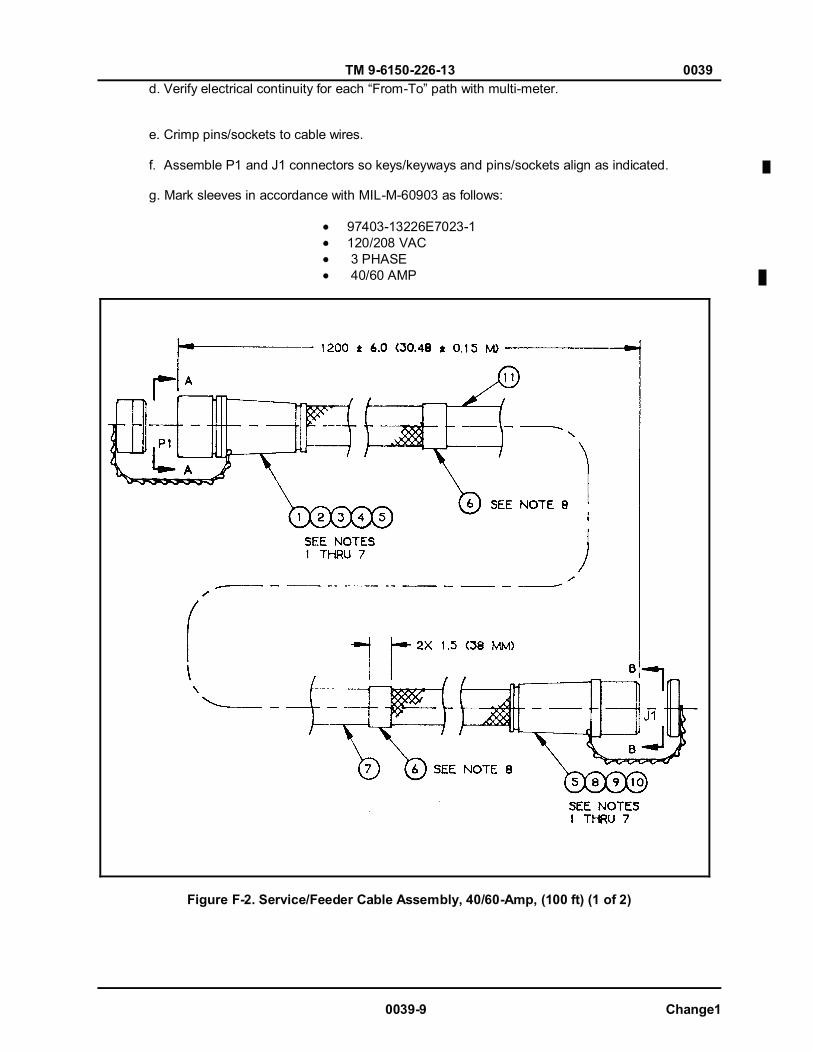
TM 9-6150-226-13 0039
0039-9 Change1
d. Verify electrical continuity for each “From-To” path with multi-meter. e. Crimp pins/sockets to cable wires. f. Assemble P1 and J1 connectors so keys/keyways and pins/sockets align as indicated. g. Mark sleeves in accordance with MIL-M-60903 as follows:
97403-13226E7023-1 120/208 VAC 3 PHASE 40/60 AMP
Figure F-2. Service/Feeder Cable Assembly, 40/60-Amp, (100 ft) (1 of 2)
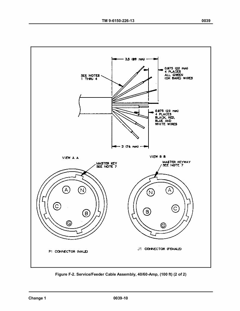
TM 9-6150-226-13 0039
Change 1 0039-10
Figure F-2. Service/Feeder Cable Assembly, 40/60-Amp, (100 ft) (2 of 2)
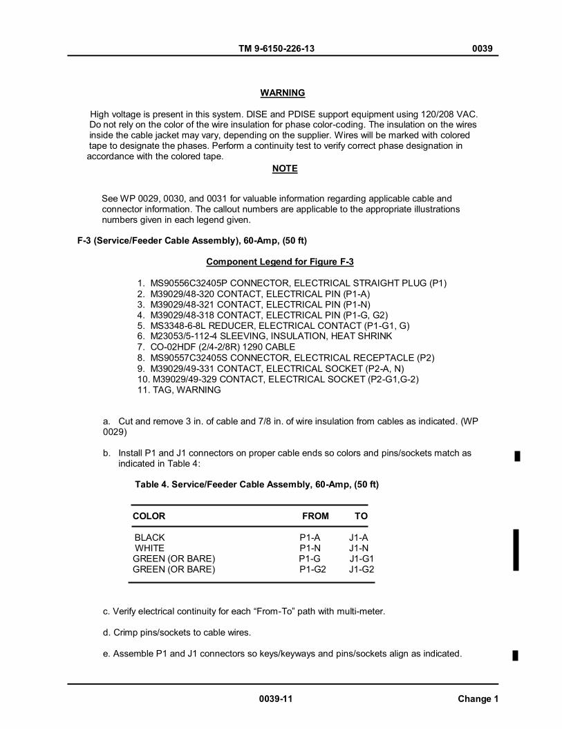
TM 9-6150-226-13 0039
0039-11 Change 1
WARNING
High voltage is present in this system. DISE and PDISE support equipment using 120/208 VAC. Do not rely on the color of the wire insulation for phase color-coding. The insulation on the wires inside the cable jacket may vary, depending on the supplier. Wires will be marked with colored tape to designate the phases. Perform a continuity test to verify correct phase designation in accordance with the colored tape.
See WP 0029, 0030, and 0031 for valuable information regarding applicable cable and connector information. The callout numbers are applicable to the appropriate illustrations numbers given in each legend given.
F-3 (Service/Feeder Cable Assembly), 60-Amp, (50 ft) Component Legend for Figure F-3
1. MS90556C32405P CONNECTOR, ELECTRICAL STRAIGHT PLUG (P1) 2. M39029/48-320 CONTACT, ELECTRICAL PIN (P1-A) 3. M39029/48-321 CONTACT, ELECTRICAL PIN (P1-N) 4. M39029/48-318 CONTACT, ELECTRICAL PIN (P1-G, G2) 5. MS3348-6-8L REDUCER, ELECTRICAL CONTACT (P1-G1, G) 6. M23053/5-112-4 SLEEVING, INSULATION, HEAT SHRINK 7. CO-02HDF (2/4-2/8R) 1290 CABLE 8. MS90557C32405S CONNECTOR, ELECTRICAL RECEPTACLE (P2) 9. M39029/49-331 CONTACT, ELECTRICAL SOCKET (P2-A, N) 10. M39029/49-329 CONTACT, ELECTRICAL SOCKET (P2-G1,G-2) 11. TAG, WARNING
a. Cut and remove 3 in. of cable and 7/8 in. of wire insulation from cables as indicated. (WP 0029)
b. Install P1 and J1 connectors on proper cable ends so colors and pins/sockets match as indicated in Table 4:
Table 4. Service/Feeder Cable Assembly, 60-Amp, (50 ft) COLOR FROM TO BLACK P1-A J1-A WHITE P1-N J1-N GREEN (OR BARE) P1-G J1-G1 GREEN (OR BARE) P1-G2 J1-G2
c. Verify electrical continuity for each “From-To” path with multi-meter. d. Crimp pins/sockets to cable wires. e. Assemble P1 and J1 connectors so keys/keyways and pins/sockets align as indicated.
NOTE
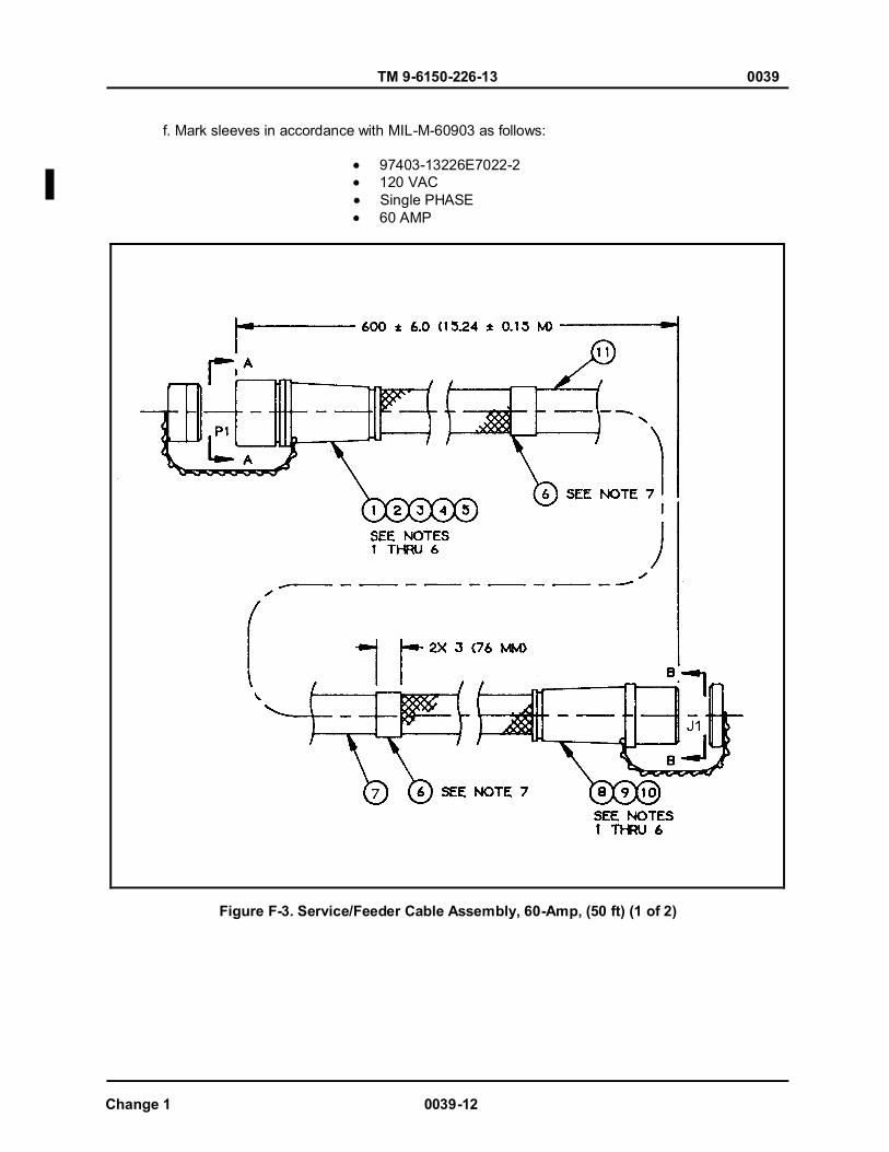
TM 9-6150-226-13 0039
Change 1 0039-12
f. Mark sleeves in accordance with MIL-M-60903 as follows:
97403-13226E7022-2 120 VAC Single PHASE 60 AMP
Figure F-3. Service/Feeder Cable Assembly, 60-Amp, (50 ft) (1 of 2)

TM 9-6150-226-13 0039
Figure F-3. Service/Feeder Cable Assembly, 60-Amp, (50 ft) (2 of 2)
0039-13 Change 1
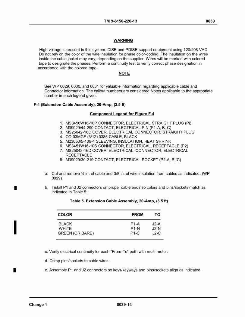
TM 9-6150-226-13 0039
Change 1 0039-14
WARNING
High voltage is present in this system. DISE and PDISE support equipment using 120/208 VAC. Do not rely on the color of the wire insulation for phase color-coding. The insulation on the wires inside the cable jacket may vary, depending on the supplier. Wires will be marked with colored tape to designate the phases. Perform a continuity test to verify correct phase designation in accordance with the colored tape.
See WP 0029, 0030, and 0031 for valuable information regarding applicable cable and Connector information. The callout numbers are considered Notes applicable to the appropriate number in each legend given.
F-4 (Extension Cable Assembly), 20-Amp, (3.5 ft) Component Legend for Figure F-4
1. MS3456W16-10P CONNECTOR, ELECTRICAL STRAIGHT PLUG (Pi) 2. M39029/44-290 CONTACT, ELECTRICAL PIN (P1-A, B, C) 3. MS25042-16D COVER, ELECTRICAL CONNECTOR, STRAIGHT PLUG 4. CO-03MGF (3/12) 0385 CABLE, BLACK 5. M23053/5-109-4 SLEEVING, INSULATION, HEAT SHRINK 6. MS3451W16-10S CONNECTOR, ELECTRICAL, RECEPTACLE (P2) 7. MS25043-16D COVER, ELECTRICAL, CONNECTOR, ELECTRICAL RECEPTACLE 8. M39029/30-219 CONTACT, ELECTRICAL SOCKET (P2-A, B, C)
a. Cut and remove ½ in. of cable and 3/8 in. of wire insulation from cables as indicated. (WP 0029)
b. Install P1 and J2 connectors on proper cable ends so colors and pins/sockets match as indicated in Table 5:
Table 5. Extension Cable Assembly, 20-Amp, (3.5 ft) COLOR FROM TO BLACK P1-A J2-A WHITE P1-N J2-N GREEN (OR BARE) P1-C J2-C
c. Verify electrical continuity for each “From-To” path with multi-meter. d. Crimp pins/sockets to cable wires. e. Assemble P1 and J2 connectors so keys/keyways and pins/sockets align as indicated.
NOTE

TM 9-6150-226-13 0039
0039-15 Change 1
f. Mark sleeves in accordance with MIL-M-60903 as follows:
97403-13226E7032-4 120 VAC Single PHASE 20 AMP
Figure F-4. Extension Cable Assembly, 20-Amp, (3.5 ft) (1 of 2)
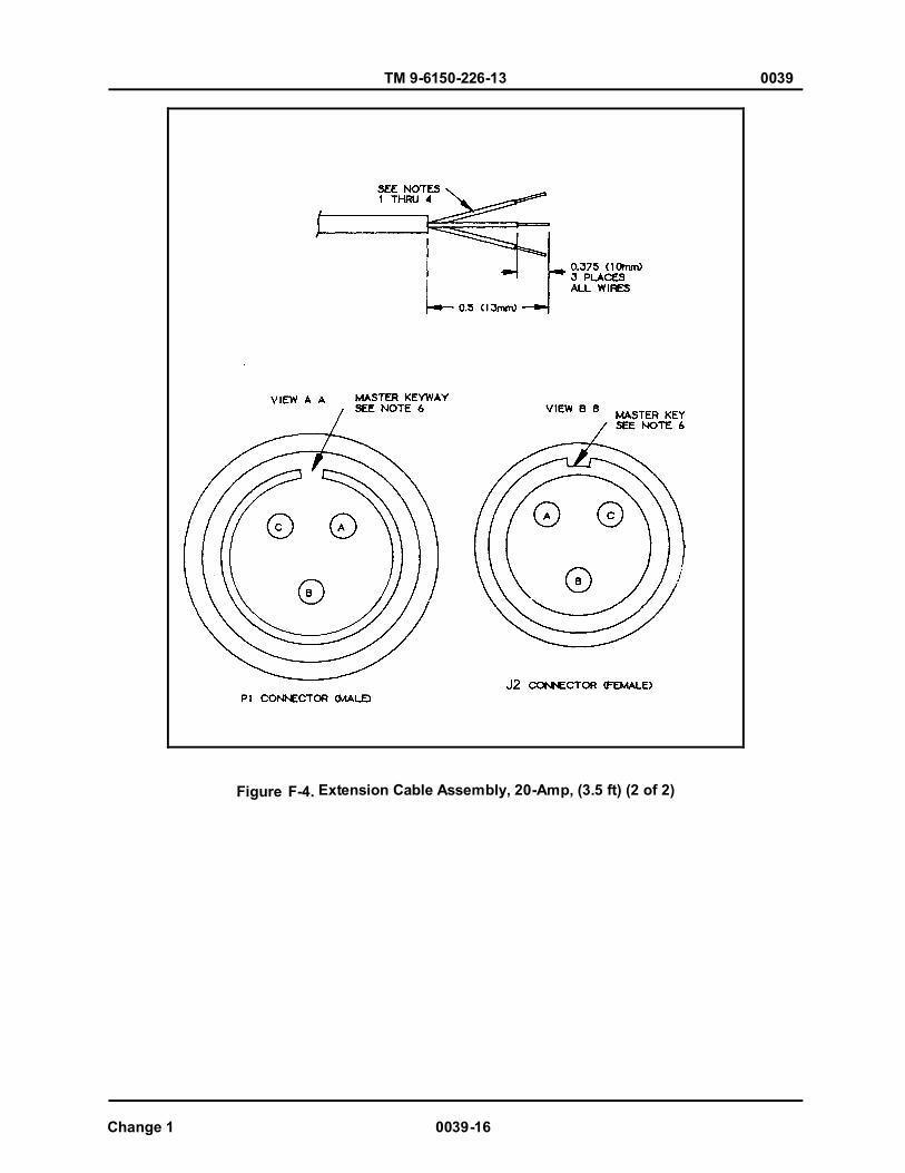
TM 9-6150-226-13 0039
Change 1 0039-16
Figure F-4. Extension Cable Assembly, 20-Amp, (3.5 ft) (2 of 2)
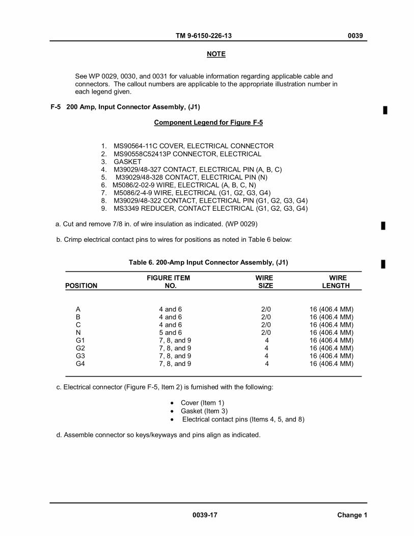
TM 9-6150-226-13 0039
0039-17 Change 1
See WP 0029, 0030, and 0031 for valuable information regarding applicable cable and connectors. The callout numbers are applicable to the appropriate illustration number in each legend given. F-5 200 Amp, Input Connector Assembly, (J1)
Component Legend for Figure F-5
1. MS90564-11C COVER, ELECTRICAL CONNECTOR 2. MS90558C52413P CONNECTOR, ELECTRICAL 3. GASKET 4. M39029/48-327 CONTACT, ELECTRICAL PIN (A, B, C) 5. M39029/48-328 CONTACT, ELECTRICAL PIN (N) 6. M5086/2-02-9 WIRE, ELECTRICAL (A, B, C, N) 7. M5086/2-4-9 WIRE, ELECTRICAL (G1, G2, G3, G4) 8. M39029/48-322 CONTACT, ELECTRICAL PIN (G1, G2, G3, G4) 9. MS3349 REDUCER, CONTACT ELECTRICAL (G1, G2, G3, G4)
a. Cut and remove 7/8 in. of wire insulation as indicated. (WP 0029) b. Crimp electrical contact pins to wires for positions as noted in Table 6 below:
Table 6. 200-Amp Input Connector Assembly, (J1)
FIGURE ITEM WIRE WIRE POSITION NO. SIZE LENGTH
A 4 and 6 2/0 16 (406.4 MM) B 4 and 6 2/0 16 (406.4 MM) C 4 and 6 2/0 16 (406.4 MM) N 5 and 6 2/0 16 (406.4 MM) G1 7, 8, and 9 4 16 (406.4 MM) G2 7, 8, and 9 4 16 (406.4 MM) G3 7, 8, and 9 4 16 (406.4 MM) G4 7, 8, and 9 4 16 (406.4 MM)
c. Electrical connector (Figure F-5, Item 2) is furnished with the following:
Cover (Item 1) Gasket (Item 3) Electrical contact pins (Items 4, 5, and 8)
d. Assemble connector so keys/keyways and pins align as indicated.
NOTE
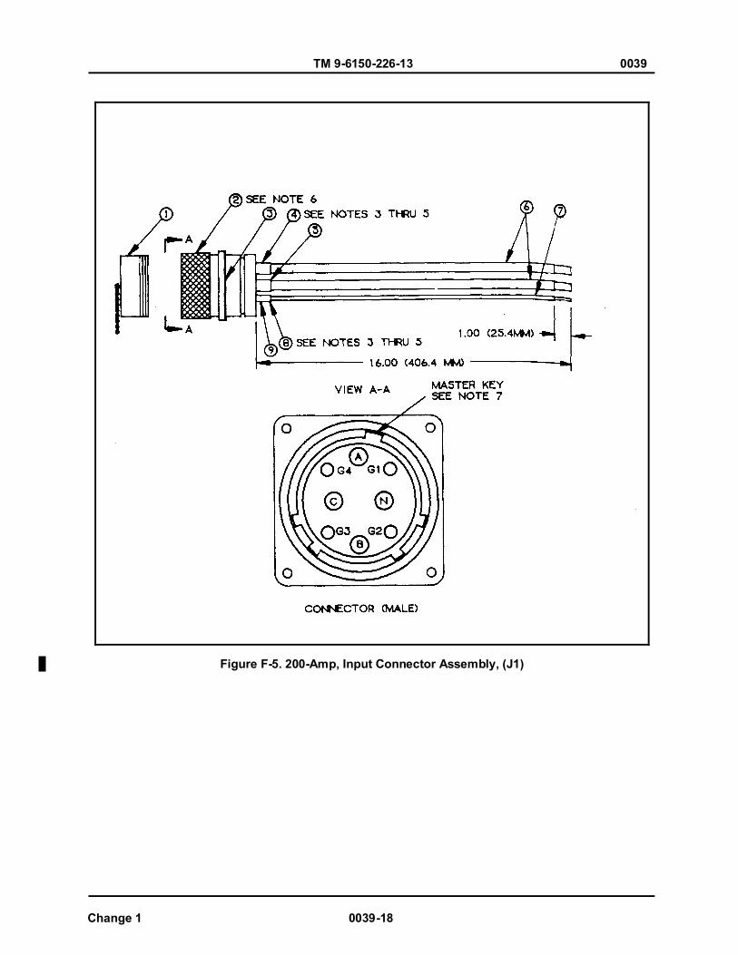
TM 9-6150-226-13 0039
Change 1 0039-18
Figure F-5. 200-Amp, Input Connector Assembly, (J1)
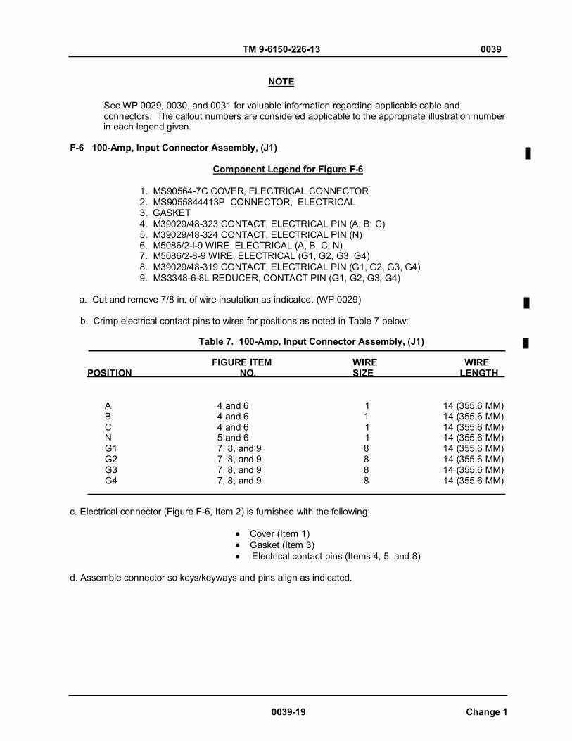
TM 9-6150-226-13 0039
0039-19 Change 1
See WP 0029, 0030, and 0031 for valuable information regarding applicable cable and connectors. The callout numbers are considered applicable to the appropriate illustration number in each legend given. F-6 100-Amp, Input Connector Assembly, (J1)
Component Legend for Figure F-6
1. MS90564-7C COVER, ELECTRICAL CONNECTOR 2. MS9055844413P CONNECTOR, ELECTRICAL 3. GASKET 4. M39029/48-323 CONTACT, ELECTRICAL PIN (A, B, C) 5. M39029/48-324 CONTACT, ELECTRICAL PIN (N) 6. M5086/2-l-9 WIRE, ELECTRICAL (A, B, C, N) 7. M5086/2-8-9 WIRE, ELECTRICAL (G1, G2, G3, G4) 8. M39029/48-319 CONTACT, ELECTRICAL PIN (G1, G2, G3, G4) 9. MS3348-6-8L REDUCER, CONTACT PIN (G1, G2, G3, G4)
a. Cut and remove 7/8 in. of wire insulation as indicated. (WP 0029) b. Crimp electrical contact pins to wires for positions as noted in Table 7 below:
Table 7. 100-Amp, Input Connector Assembly, (J1)
FIGURE ITEM WIRE WIRE POSITION NO. SIZE LENGTH
A 4 and 6 1 14 (355.6 MM) B 4 and 6 1 14 (355.6 MM) C 4 and 6 1 14 (355.6 MM) N 5 and 6 1 14 (355.6 MM) G1 7, 8, and 9 8 14 (355.6 MM) G2 7, 8, and 9 8 14 (355.6 MM) G3 7, 8, and 9 8 14 (355.6 MM) G4 7, 8, and 9 8 14 (355.6 MM)
c. Electrical connector (Figure F-6, Item 2) is furnished with the following:
Cover (Item 1) Gasket (Item 3) Electrical contact pins (Items 4, 5, and 8)
d. Assemble connector so keys/keyways and pins align as indicated.
NOTE

TM 9-6150-226-13 0039
Change 1 0039-20
Figure F-6. 100-Amp, Input Connector Assembly, (J1)

TM 9-6150-226-13 0039
0039-21 Change 1
See WP 0029, 0030, and 0031 for valuable information regarding applicable cable and connectors. The callout numbers are considered Notes applicable to the appropriate number in each legend given. F-7 M200, 100-Amp Output Connectors, (J4, J5, J11) M100, 100-Amp Output Connector, (J2)
Component Legend for Figure F-7
1. MS90563-7C COVER, ELECTRICAL CONNECTOR 2. MS9055C44413S CONNECTOR, ELECTRICAL RECEPTACLE 3. GASKET 4. M39029/49-333 CONTACT, ELECTRICAL SOCKET (A, B, C, N) 5. M5086/2-1-9 WIRE, ELECTRICAL (A, B, C, N) 6. M5086/2-8-9 WIRE, ELECTRICAL (G1, G2, G3, G4) 7. M39029/49-330 CONTACT, ELECTRICAL SOCKET (G1, G2, G3, G4) 8. MS3348-6-8L REDUCER, ELECTRICAL CONTACT (G1, G2, G3, G4)
a. Cut and remove 7/8 in. of wire insulation as indicated. (WP 0029). b. Crimp electrical contact pins to wires for positions as noted in Table 8 below:
Table 8. M200/100, 100-Amp, Output Connector Assemblies,
FIGURE ITEM WIRE WIRE POSITION NO. SIZE LENGTH
A 4 and 6 1 14 (355.6 MM) B 4 and 6 1 14 (355.6 MM) C 4 and 6 1 14 (355.6 MM) N 5 and 6 1 14 (355.6 MM) G1 7, 8, and 9 8 14 (355.6 MM) G2 7, 8, and 9 8 14 (355.6 MM) G3 7, 8, and 9 8 14 (355.6 MM) G4 7, 8, and 9 8 14 (355.6 MM)
c. Electrical connector (Figure F-7, Item 2) is furnished with the following:
Cover (Item 1) Gasket (Item 3) Electrical contact pins (Items 4 and 7)
d. Assemble connector so keys/keyways and pins align as indicated.
NOTE

TM 9-6150-226-13 0039
Change 1 0039-22
Figure F-7. M200/100, 100-Amp, Output Connector Assemblies.
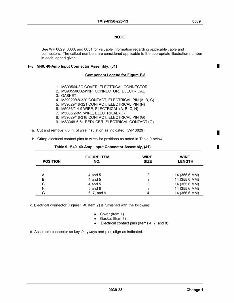
TM 9-6150-226-13 0039
0039-23 Change 1
See WP 0029, 0030, and 0031 for valuable information regarding applicable cable and connectors. The callout numbers are considered applicable to the appropriate illustration number in each legend given. F-8 M40, 40-Amp Input Connector Assembly, (J1)
Component Legend for Figure F-8
1. MS90564-3C COVER, ELECTRICAL CONNECTOR 2. MS90558C32413P CONNECTOR, ELECTRICAL 3. GASKET 4. M39029/48-320 CONTACT, ELECTRICAL PIN (A, B, C) 5. M39029/48-321 CONTACT, ELECTRICAL PIN (N) 6. M5086/2-4-9 WIRE, ELECTRICAL (A, B, C, N) 7. M5086/2-8-9 WIRE, ELECTRICAL (G) 8. M39029/48-318 CONTACT, ELECTRICAL PIN (G) 9. MS3348-6-8L REDUCER, ELECTRICAL CONTACT (G)
a. Cut and remove 7/8 in. of wire insulation as indicated. (WP 0029) b. Crimp electrical contact pins to wires for positions as noted in Table 9 below:
Table 9. M40, 40-Amp, Input Connector Assembly, (J1)
FIGURE ITEM WIRE WIRE POSITION NO. SIZE LENGTH
A 4 and 5 3 14 (355.6 MM) B 4 and 5 3 14 (355.6 MM) C 4 and 5 3 14 (355.6 MM) N 5 and 8 3 14 (355.6 MM) G 6, 7, and 9 4 14 (355.6 MM)
c. Electrical connector (Figure F-8, Item 2) is furnished with the following:
Cover (Item 1) Gasket (Item 3) Electrical contact pins (Items 4, 7, and 8)
d. Assemble connector so keys/keyways and pins align as indicated.
NOTE
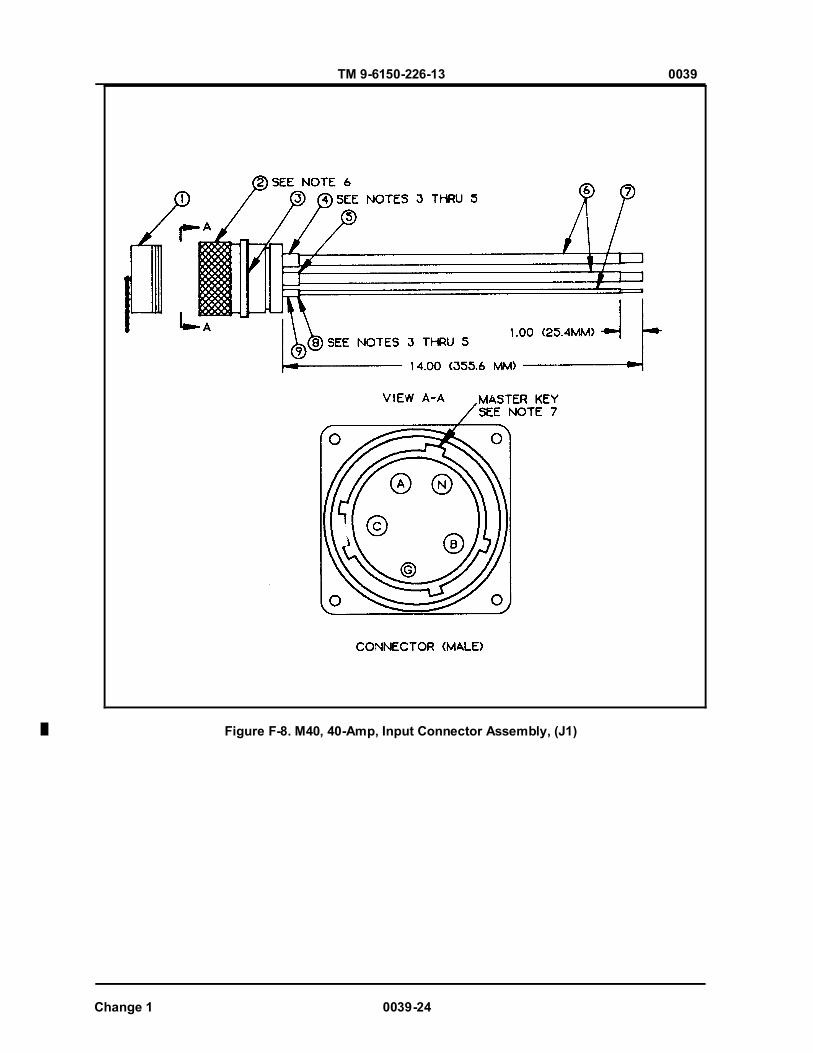
TM 9-6150-226-13 0039
Change 1 0039-24
Figure F-8. M40, 40-Amp, Input Connector Assembly, (J1)
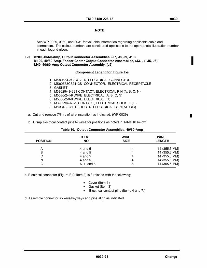
TM 9-6150-226-13 0039
0039-25 Change 1
See WP 0029, 0030, and 0031 for valuable information regarding applicable cable and connectors. The callout numbers are considered applicable to the appropriate illustration number in each legend given. F-9 M200, 40/60-Amp, Output Connector Assemblies, (J7, J8, J9, J10) M100, 40/60-Amp, Feeder Center Output Connector Assemblies, (J3, J4, J5, J6) M40, 40/60-Amp Output Connector Assembly, (J2)
Component Legend for Figure F-9
1. MS90564-3C COVER, ELECTRICAL CONNECTOR 2. MS90558C32413S CONNECTOR, ELECTRICAL RECEPTACLE 3. GASKET 4. M39029/49-331 CONTACT, ELECTRICAL PIN (A, B, C, N) 5. M5086/2-4-9 WIRE, ELECTRICAL (A, B, C, N) 6. M5086/2-8-9 WIRE, ELECTRICAL (G) 7. M39029/49-329 CONTACT, ELECTRICAL SOCKET (G) 8. MS3348-6-8L REDUCER, ELECTRICAL CONTACT (G)
a. Cut and remove 7/8 in. of wire insulation as indicated. (WP 0029) b. Crimp electrical contact pins to wires for positions as noted in Table 10 below:
Table 10. Output Connector Assemblies, 40/60-Amp ITEM WIRE WIRE POSITION NO. SIZE LENGTH
A 4 and 5 4 14 (355.6 MM) B 4 and 5 4 14 (355.6 MM) C 4 and 5 4 14 (355.6 MM) N 4 and 5 4 14 (355.6 MM) G 6, 7, and 8 8 14 (355.6 MM)
c. Electrical connector (Figure F-9, Item 2) is furnished with the following:
Cover (Item 1) Gasket (Item 3) Electrical contact pins (Items 4 and 7,)
d. Assemble connector so keys/keyways and pins align as indicated.
NOTE
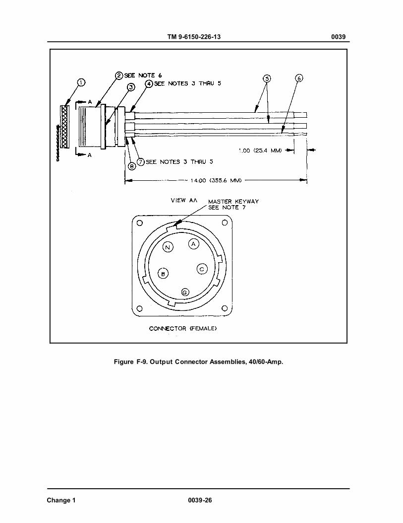
TM 9-6150-226-13 0039
Change 1 0039-26
Figure F-9. Output Connector Assemblies, 40/60-Amp.
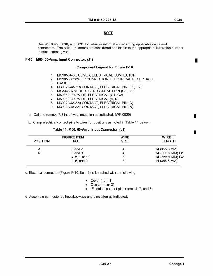
TM 9-6150-226-13 0039
See WP 0029, 0030, and 0031 for valuable information regarding applicable cable and connectors. The callout numbers are considered applicable to the appropriate illustration number in each legend given. F-10 M60, 60-Amp, Input Connector, (J1)
Component Legend for Figure F-10
1. MS90564-3C COVER, ELECTRICAL CONNECTOR 2. MS90558C32405P CONNECTOR, ELECTRICAL RECEPTACLE 3. GASKET 4. M39029/48-318 CONTACT, ELECTRICAL PIN (G1, G2) 5. MS3348-6-8L REDUCER, CONTACT PIN (G1, G2) 6. M5086/2-8-9 WIRE, ELECTRICAL (G1, G2) 7. M5086/2-4-9 WIRE, ELECTRICAL (A, N) 8. M39029/48-320 CONTACT, ELECTRICAL PIN (A) 9. M39029/48-321 CONTACT, ELECTRICAL PIN (N)
a. Cut and remove 7/8 in. of wire insulation as indicated. (WP 0029) b. Crimp electrical contact pins to wires for positions as noted in Table 11 below:
Table 11. M60, 60-Amp, Input Connector, (J1)
FIGURE ITEM WIRE WIRE POSITION NO. SIZE LENGTH
A 6 and 7 4 14 (355.6 MM) N 6 and 8 4 14 (355.6 MM) G1 4, 5, 1 and 9 8 14 (355.6 MM) G2 4, 5, and 9 8 14 (355.6 MM)
c. Electrical connector (Figure F-10, Item 2) is furnished with the following:
Cover (Item 1) Gasket (Item 3) Electrical contact pins (Items 4, 7, and 8)
d. Assemble connector so keys/keyways and pins align as indicated.
NOTE
0039-27 Change 1
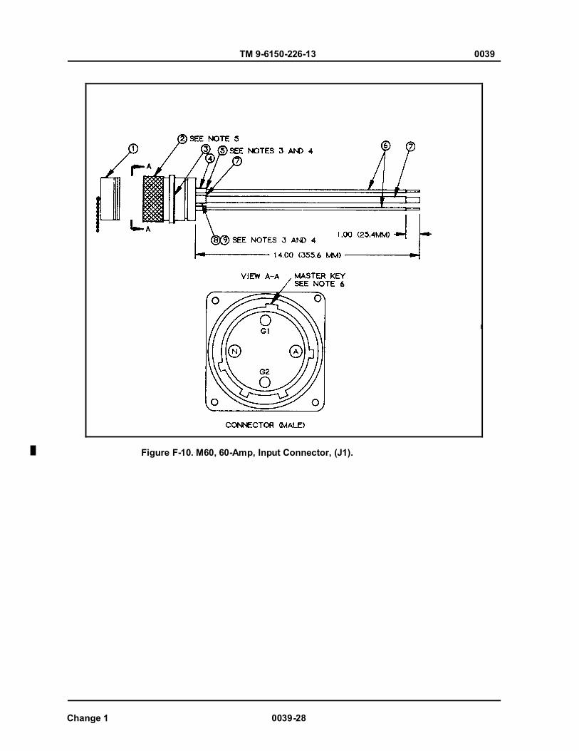
TM 9-6150-226-13 0039
Change 1 0039-28
Figure F-10. M60, 60-Amp, Input Connector, (J1).
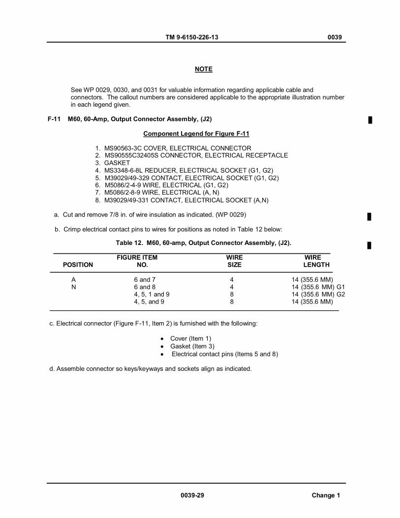
TM 9-6150-226-13 0039
0039-29 Change 1
See WP 0029, 0030, and 0031 for valuable information regarding applicable cable and connectors. The callout numbers are considered applicable to the appropriate illustration number in each legend given. F-11 M60, 60-Amp, Output Connector Assembly, (J2)
Component Legend for Figure F-11
1. MS90563-3C COVER, ELECTRICAL CONNECTOR 2. MS90555C32405S CONNECTOR, ELECTRICAL RECEPTACLE 3. GASKET 4. MS3348-6-8L REDUCER, ELECTRICAL SOCKET (G1, G2) 5. M39029/49-329 CONTACT, ELECTRICAL SOCKET (G1, G2) 6. M5086/2-4-9 WlRE, ELECTRICAL (G1, G2) 7. M5086/2-8-9 WlRE, ELECTRICAL (A, N) 8. M39029/49-331 CONTACT, ELECTRICAL SOCKET (A,N)
a. Cut and remove 7/8 in. of wire insulation as indicated. (WP 0029) b. Crimp electrical contact pins to wires for positions as noted in Table 12 below:
Table 12. M60, 60-amp, Output Connector Assembly, (J2).
FIGURE ITEM WIRE WIRE POSITION NO. SIZE LENGTH
A 6 and 7 4 14 (355.6 MM) N 6 and 8 4 14 (355.6 MM) G1 4, 5, 1 and 9 8 14 (355.6 MM) G2 4, 5, and 9 8 14 (355.6 MM)
c. Electrical connector (Figure F-11, Item 2) is furnished with the following:
Cover (Item 1) Gasket (Item 3) Electrical contact pins (Items 5 and 8)
d. Assemble connector so keys/keyways and sockets align as indicated.
NOTE

TM 9-6150-226-13 0039
Figure F-11. M60, 60-Amp, Output Connector Assembly.
Change 1 0039-30

TM 9-6150-226-13 0039
0039-31 Change 1
See WP 0029, 0030, and 0031 for valuable information regarding applicable cable and connectors. The callout numbers are considered applicable to the appropriate illustration number in each legend given. F-12 M40, 20-Amp, Output Connectors, (J3 thru J14) M60, 20-Amp Output Connectors, (J3 thru J8)
Component Legend for Figure F-12
1. MS25043-16D COVER, ELECTRICAL CONNECTOR 2. MS3402D16-10S CONNECTOR, ELECTRICAL RECEPTACLE 3. GASKET 4. M5086/2-12-9 WIRE, ELECTRICAL (A, B, C) 5. M39029/30-219 SOCKET, ELECTRICAL CONTACT (A, B, C)
a. Cut and remove ½ in. of wire insulation as indicated. b. Crimp electrical contact pins to wires for positions as noted in Table 13 below:
Table 13. Output Connector Assemblies, 20-Amp.
FIGURE ITEM WIRE WIRE POSITION NO. SIZE LENGTH
A 4 and 5 12 11 (279.4 MM) B 4 and 5 12 13 (330.2 MM) C 4 and 5 12 11 (279.4 MM)
c. Electrical connector (Figure F-12, Item 2) is furnished with the following:
Cover (Item 1) Gasket (Item 3) Electrical contact sockets (Items 5)
d. Assemble connector so keys/keyways and pins align as indicated.
NOTE

TM 9-6150-226-13 0039
Change 1 0039-32
Figure F-12. Output Connector Assemblies, 20–Amp.
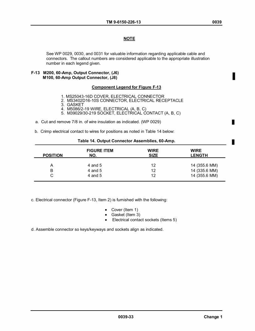
TM 9-6150-226-13 0039
0039-33 Change 1
See WP 0029, 0030, and 0031 for valuable information regarding applicable cable and connectors. The callout numbers are considered applicable to the appropriate illustration number in each legend given. F-13 M200, 60-Amp, Output Connector, (J6) M100, 60-Amp Output Connector, (J8)
Component Legend for Figure F-13
1. MS25043-16D COVER, ELECTRICAL CONNECTOR 2. MS3402D16-10S CONNECTOR, ELECTRICAL RECEPTACLE
3. GASKET 4. M5086/2-19 WIRE, ELECTRICAL (A, B, C) 5. M39029/30-219 SOCKET, ELECTRICAL CONTACT (A, B, C) a. Cut and remove 7/8 in. of wire insulation as indicated. (WP 0029) b. Crimp electrical contact to wires for positions as noted in Table 14 below:
Table 14. Output Connector Assemblies, 60-Amp.
FIGURE ITEM WIRE WIRE POSITION NO. SIZE LENGTH
A 4 and 5 12 14 (355.6 MM) B 4 and 5 12 14 (335.6 MM) C 4 and 5 12 14 (355.6 MM)
c. Electrical connector (Figure F-13, Item 2) is furnished with the following:
Cover (Item 1) Gasket (Item 3)
Electrical contact sockets (Items 5)
d. Assemble connector so keys/keyways and sockets align as indicated.
NOTE
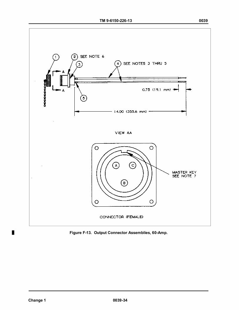
TM 9-6150-226-13 0039
Figure F-13. Output Connector Assemblies, 60-Amp.
Change 1 0039-34
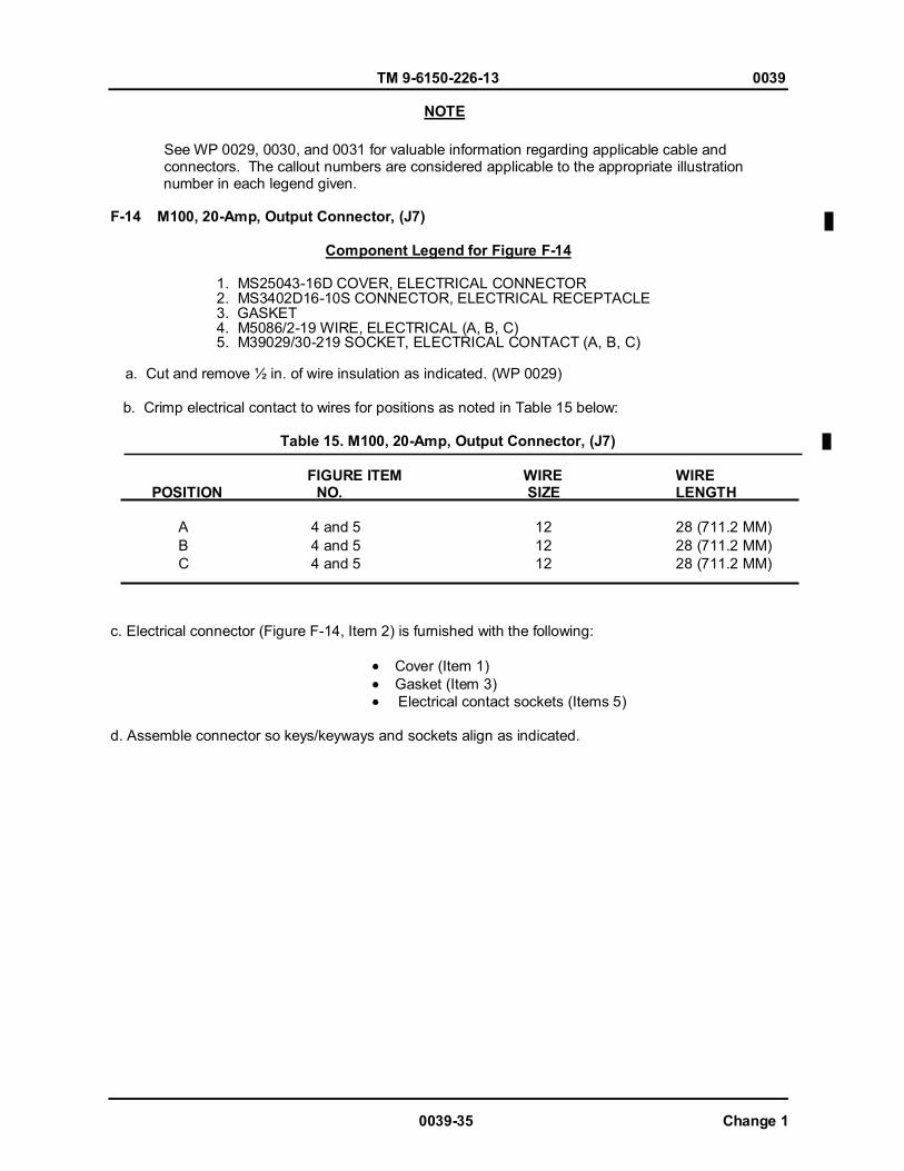
TM 9-6150-226-13 0039
0039-35 Change 1
See WP 0029, 0030, and 0031 for valuable information regarding applicable cable and connectors. The callout numbers are considered applicable to the appropriate illustration number in each legend given. F-14 M100, 20-Amp, Output Connector, (J7)
Component Legend for Figure F-14
1. MS25043-16D COVER, ELECTRICAL CONNECTOR 2. MS3402D16-10S CONNECTOR, ELECTRICAL RECEPTACLE 3. GASKET 4. M5086/2-19 WIRE, ELECTRICAL (A, B, C) 5. M39029/30-219 SOCKET, ELECTRICAL CONTACT (A, B, C)
a. Cut and remove ½ in. of wire insulation as indicated. (WP 0029) b. Crimp electrical contact to wires for positions as noted in Table 15 below:
Table 15. M100, 20-Amp, Output Connector, (J7)
FIGURE ITEM WIRE WIRE POSITION NO. SIZE LENGTH
A 4 and 5 12 28 (711.2 MM) B 4 and 5 12 28 (711.2 MM) C 4 and 5 12 28 (711.2 MM)
c. Electrical connector (Figure F-14, Item 2) is furnished with the following:
Cover (Item 1) Gasket (Item 3) Electrical contact sockets (Items 5)
d. Assemble connector so keys/keyways and sockets align as indicated.
NOTE
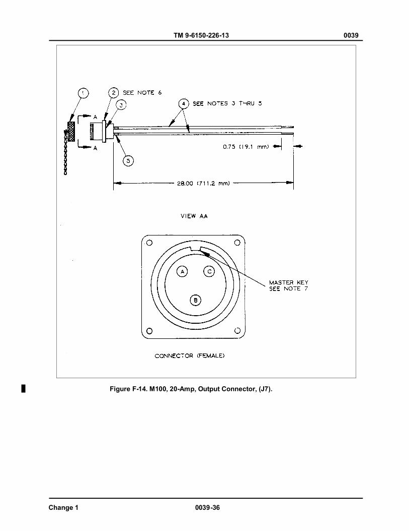
TM 9-6150-226-13 0039
Figure F-14. M100, 20-Amp, Output Connector, (J7).
Change 1 0039-36
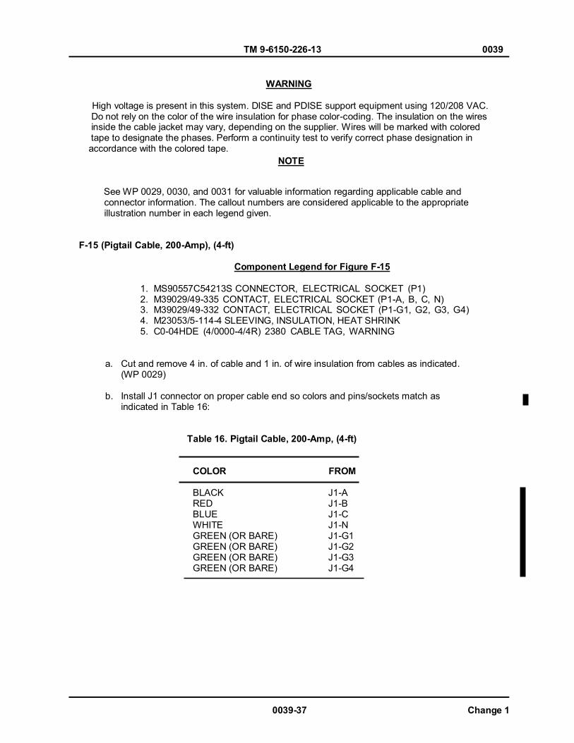
TM 9-6150-226-13 0039
WARNING
High voltage is present in this system. DISE and PDISE support equipment using 120/208 VAC. Do not rely on the color of the wire insulation for phase color-coding. The insulation on the wires inside the cable jacket may vary, depending on the supplier. Wires will be marked with colored tape to designate the phases. Perform a continuity test to verify correct phase designation in accordance with the colored tape.
See WP 0029, 0030, and 0031 for valuable information regarding applicable cable and connector information. The callout numbers are considered applicable to the appropriate illustration number in each legend given.
F-15 (Pigtail Cable, 200-Amp), (4-ft) Component Legend for Figure F-15
1. MS90557C54213S CONNECTOR, ELECTRICAL SOCKET (P1) 2. M39029/49-335 CONTACT, ELECTRICAL SOCKET (P1-A, B, C, N) 3. M39029/49-332 CONTACT, ELECTRICAL SOCKET (P1-G1, G2, G3, G4) 4. M23053/5-114-4 SLEEVING, INSULATION, HEAT SHRINK
5. C0-04HDE (4/0000-4/4R) 2380 CABLE TAG, WARNING
a. Cut and remove 4 in. of cable and 1 in. of wire insulation from cables as indicated. (WP 0029)
b. Install J1 connector on proper cable end so colors and pins/sockets match as indicated in Table 16:
Table 16. Pigtail Cable, 200-Amp, (4-ft)
COLOR FROM BLACK RED BLUE WHITE GREEN (OR BARE) GREEN (OR BARE) GREEN (OR BARE) GREEN (OR BARE)
J1-A J1-B J1-C J1-N J1-G1 J1-G2 J1-G3 J1-G4
NOTE
0039-37 Change 1
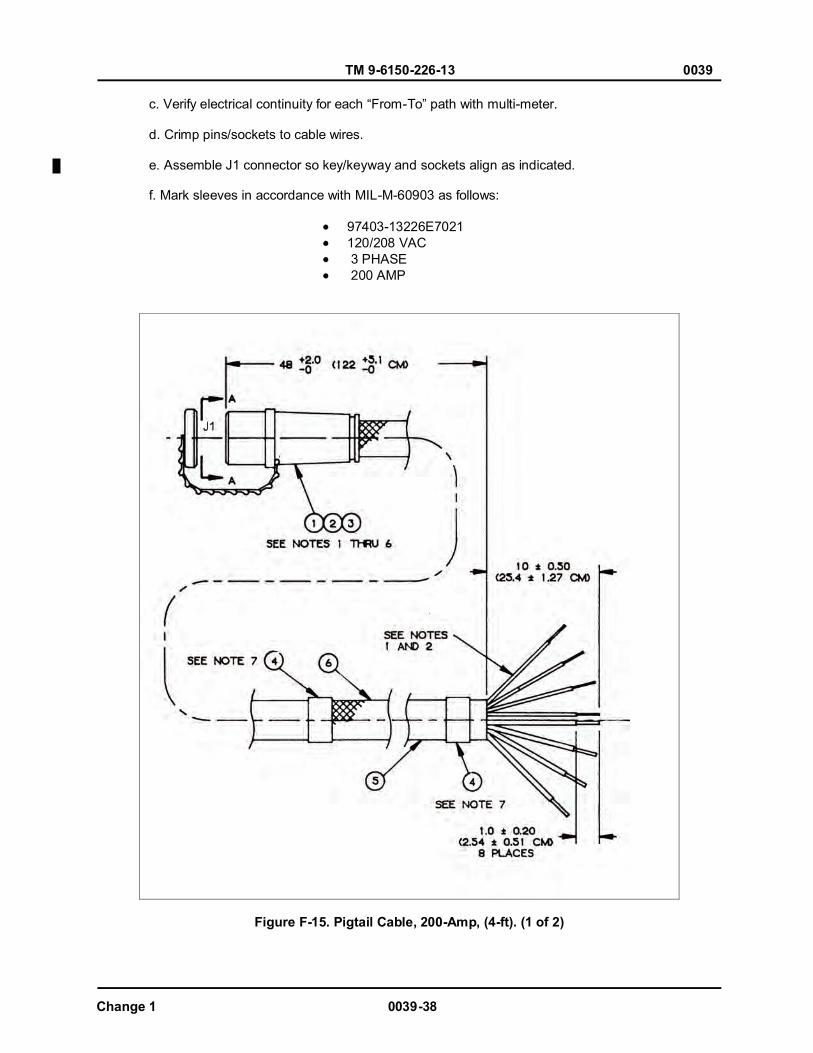
TM 9-6150-226-13 0039
Change 1 0039-38
c. Verify electrical continuity for each “From-To” path with multi-meter. d. Crimp pins/sockets to cable wires. e. Assemble J1 connector so key/keyway and sockets align as indicated. f. Mark sleeves in accordance with MIL-M-60903 as follows:
97403-13226E7021 120/208 VAC 3 PHASE 200 AMP
Figure F-15. Pigtail Cable, 200-Amp, (4-ft). (1 of 2)
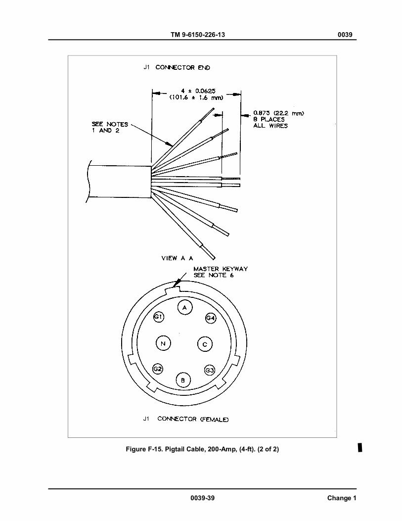
TM 9-6150-226-13 0039
0039-39 Change 1
Figure F-15. Pigtail Cable, 200-Amp, (4-ft). (2 of 2)
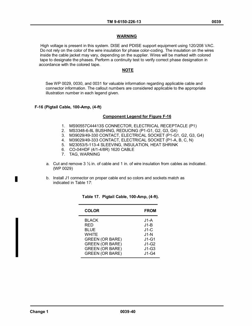
TM 9-6150-226-13 0039
Change 1 0039-40
WARNING
High voltage is present in this system. DISE and PDISE support equipment using 120/208 VAC. Do not rely on the color of the wire insulation for phase color-coding. The insulation on the wires inside the cable jacket may vary, depending on the supplier. Wires will be marked with colored tape to designate the phases. Perform a continuity test to verify correct phase designation in accordance with the colored tape.
See WP 0029, 0030, and 0031 for valuable information regarding applicable cable and connector information. The callout numbers are considered applicable to the appropriate illustration number in each legend given.
F-16 (Pigtail Cable, 100-Amp, (4-ft) Component Legend for Figure F-16
1. MS90557C44413S CONNECTOR, ELECTRICAL RECEPTACLE (P1) 2. MS3348-6-8L BUSHING, REDUCING (P1-G1, G2, G3, G4) 3. M39029/49-330 CONTACT, ELECTRICAL SOCKET (P1-G1, G2, G3, G4) 4. M39029/49-333 CONTACT, ELECTRICAL SOCKET (P1-A, B, C, N) 5. M23053/5-113-4 SLEEVING, INSULATION, HEAT SHRINK 6. CO-04HDF (4/1-4/8R) 1620 CABLE 7. TAG, WARNING
a. Cut and remove 3 ½ in. of cable and 1 in. of wire insulation from cables as indicated. (WP 0029)
b. Install J1 connector on proper cable end so colors and sockets match as indicated in Table 17:
Table 17. Pigtail Cable, 100-Amp, (4-ft).
COLOR FROM BLACK RED BLUE WHITE GREEN (OR BARE) GREEN (OR BARE) GREEN (OR BARE) GREEN (OR BARE)
J1-A J1-B J1-C J1-N J1-G1 J1-G2 J1-G3 J1-G4
NOTE
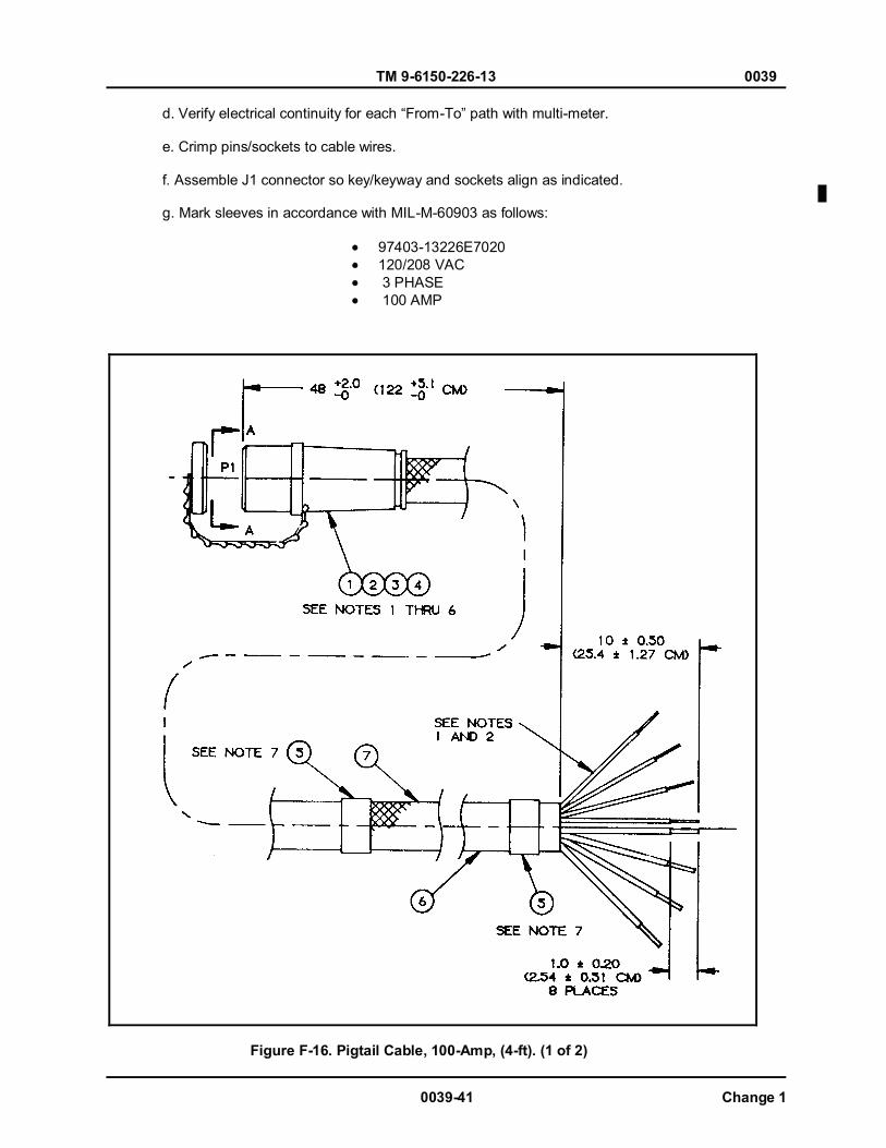
TM 9-6150-226-13 0039
0039-41 Change 1
d. Verify electrical continuity for each “From-To” path with multi-meter. e. Crimp pins/sockets to cable wires. f. Assemble J1 connector so key/keyway and sockets align as indicated. g. Mark sleeves in accordance with MIL-M-60903 as follows:
97403-13226E7020 120/208 VAC 3 PHASE 100 AMP
Figure F-16. Pigtail Cable, 100-Amp, (4-ft). (1 of 2)
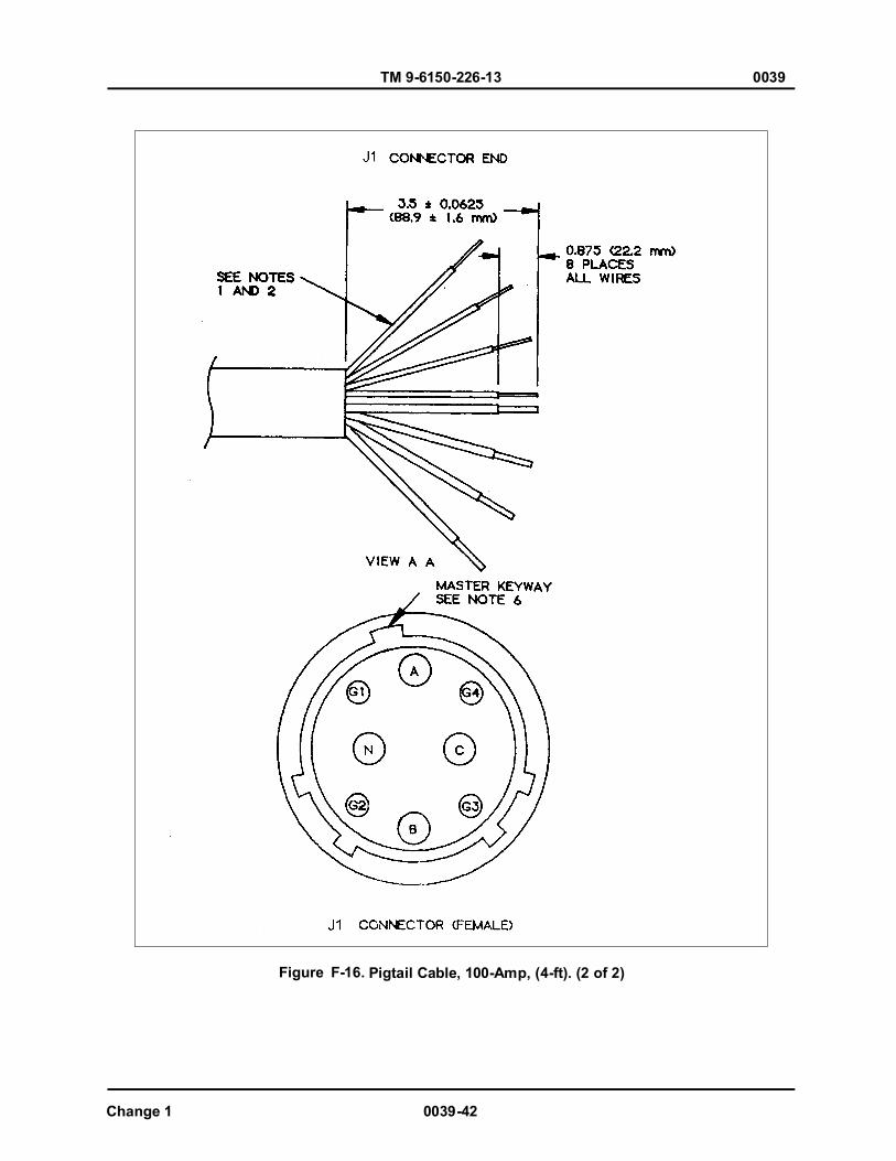
TM 9-6150-226-13 0039
Change 1 0039-42
Figure F-16. Pigtail Cable, 100-Amp, (4-ft). (2 of 2)

TM 9-6150-226-13 0039
0039-43 Change 1
WARNING
High voltage is present in this system. DISE and PDISE support equipment using 120/208 VAC. Do not rely on the color of the wire insulation for phase color-coding. The insulation on the wires inside the cable jacket may vary, depending on the supplier. Wires will be marked with colored tape to designate the phases. Perform a continuity test to verify correct phase designation in accordance with the colored tape.
See WP 0029, 0030, and 0031 for valuable information regarding applicable cable and connector information. The callout numbers are considered applicable to the appropriate illustration number in each legend given.
F-17 (Pigtail Cable), 40/60-Amp, (4-ft) Component Legend for Figure F-17
1. MS90557C32413S CONNECTOR, E1 ELECTRICAL RECEPTACLE (P1) 2. M39029/39-331 CONTACT, ELECTRICAL SOCKET (P1-A, B, C, N) 3. M39029/39-329 CONTACT, ELECTRICAL SOCKET (P1-G) 4. M23053/5-112-4 SLEEVING, INSULATION, HEAT SHRINK 5. CO-04HDF (4/4-4/1A) CABLE 6. TAG, WARNING
a. Cut and remove 4 in. of cable 1 in. of wire insulation from cables as indicated. (WP 0029)
b. Install J1 connector on proper cable end so colors and sockets match as indicated in Table 18:
Table 18. Pigtail Cable, 40/60-Amp, (4-ft)
COLOR FROM
BLACK J1-A RED J1-B BLUE J1-C WHITE J1-N GREEN (OR BARE) GREEN (OR BARE) J1-G GREEN (OR BARE) GREEN (OR BARE)
NOTE
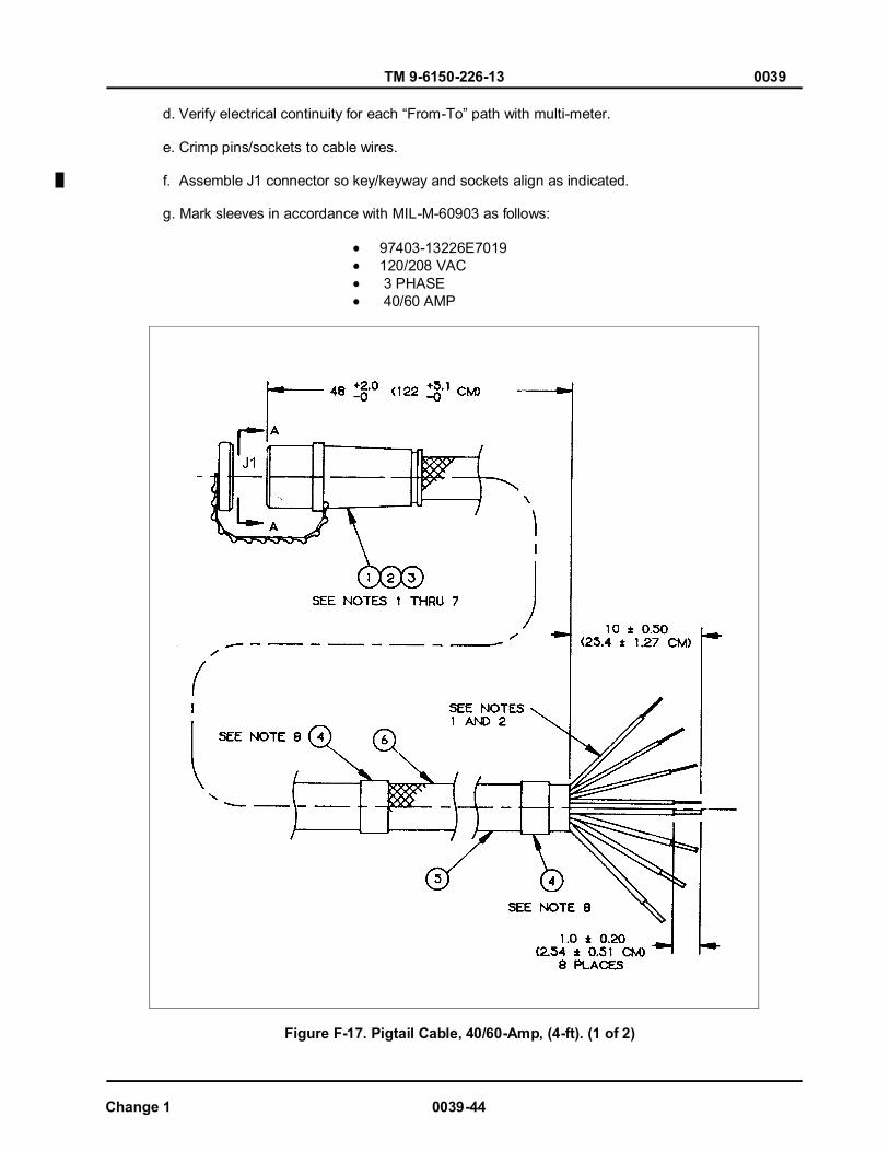
TM 9-6150-226-13 0039
Change 1 0039-44
d. Verify electrical continuity for each “From-To” path with multi-meter. e. Crimp pins/sockets to cable wires. f. Assemble J1 connector so key/keyway and sockets align as indicated. g. Mark sleeves in accordance with MIL-M-60903 as follows:
97403-13226E7019 120/208 VAC 3 PHASE 40/60 AMP
Figure F-17. Pigtail Cable, 40/60-Amp, (4-ft). (1 of 2)
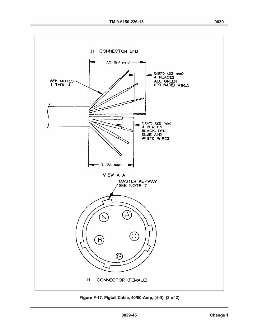
TM 9-6150-226-13 0039
0039-45 Change 1
Figure F-17. Pigtail Cable, 40/60-Amp, (4-ft). (2 of 2)
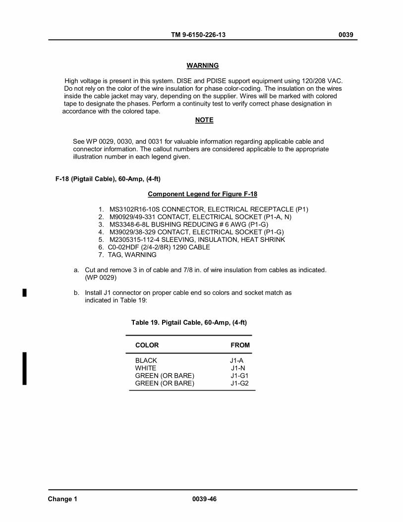
TM 9-6150-226-13 0039
Change 1 0039-46
WARNING
High voltage is present in this system. DISE and PDISE support equipment using 120/208 VAC. Do not rely on the color of the wire insulation for phase color-coding. The insulation on the wires inside the cable jacket may vary, depending on the supplier. Wires will be marked with colored tape to designate the phases. Perform a continuity test to verify correct phase designation in accordance with the colored tape.
See WP 0029, 0030, and 0031 for valuable information regarding applicable cable and connector information. The callout numbers are considered applicable to the appropriate illustration number in each legend given.
F-18 (Pigtail Cable), 60-Amp, (4-ft) Component Legend for Figure F-18
1. MS3102R16-10S CONNECTOR, ELECTRICAL RECEPTACLE (P1) 2. M90929/49-331 CONTACT, ELECTRICAL SOCKET (P1-A, N) 3. MS3348-6-8L BUSHING REDUCING # 6 AWG (P1-G) 4. M39029/38-329 CONTACT, ELECTRICAL SOCKET (P1-G) 5. M2305315-112-4 SLEEVING, INSULATION, HEAT SHRINK 6. C0-02HDF (2/4-2/8R) 1290 CABLE 7. TAG, WARNING
a. Cut and remove 3 in of cable and 7/8 in. of wire insulation from cables as indicated. (WP 0029)
b. Install J1 connector on proper cable end so colors and socket match as indicated in Table 19:
Table 19. Pigtail Cable, 60-Amp, (4-ft)
COLOR FROM BLACK J1-A
WHITE J1-N GREEN (OR BARE) J1-G1 GREEN (OR BARE) J1-G2
NOTE
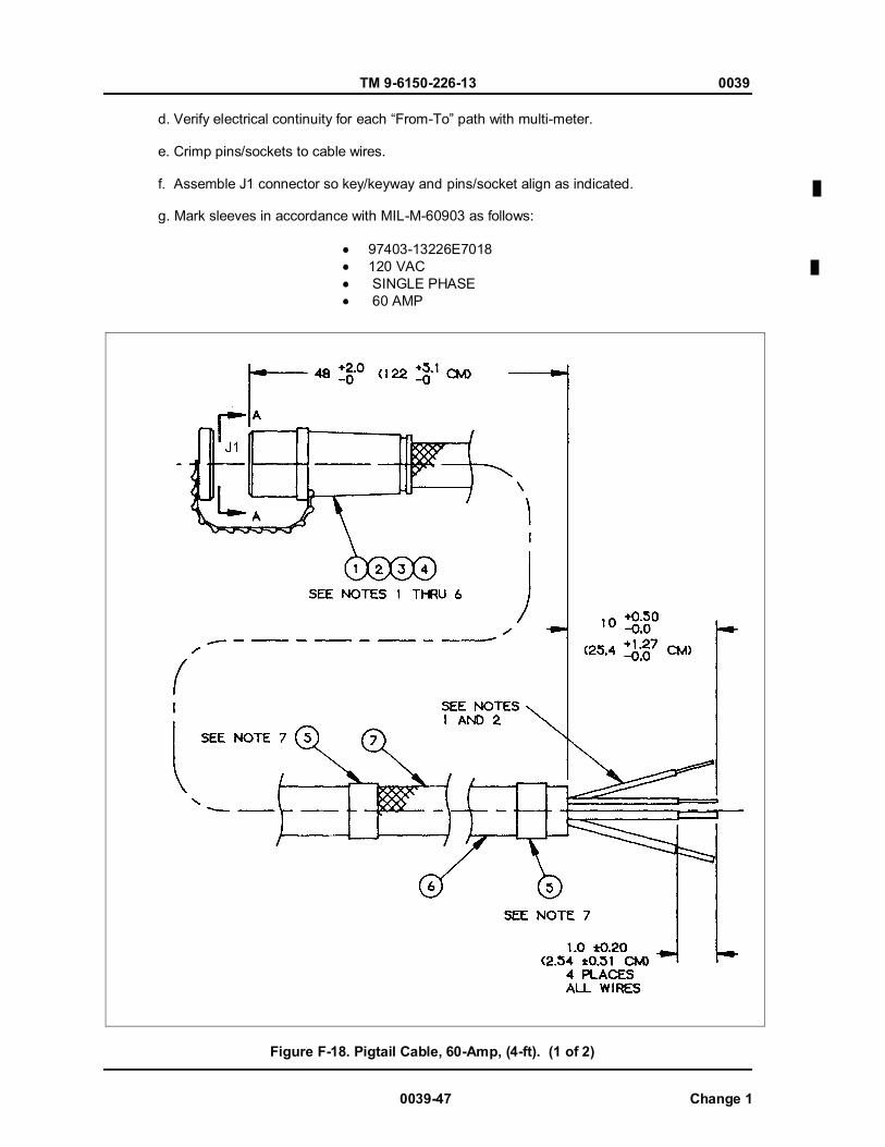
TM 9-6150-226-13 0039
0039-47 Change 1
d. Verify electrical continuity for each “From-To” path with multi-meter. e. Crimp pins/sockets to cable wires. f. Assemble J1 connector so key/keyway and pins/socket align as indicated. g. Mark sleeves in accordance with MIL-M-60903 as follows:
97403-13226E7018 120 VAC SINGLE PHASE 60 AMP
Figure F-18. Pigtail Cable, 60-Amp, (4-ft). (1 of 2)
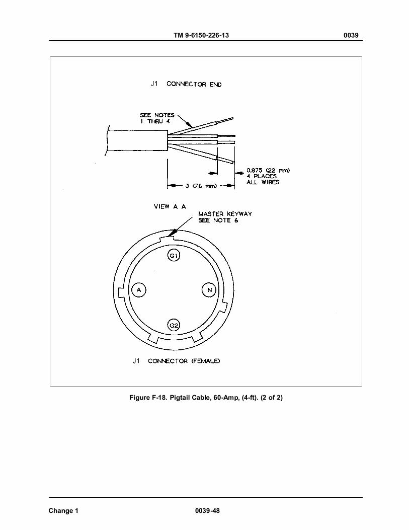
TM 9-6150-226-13 0039
Change 1 0039-48
Figure F-18. Pigtail Cable, 60-Amp, (4-ft). (2 of 2)
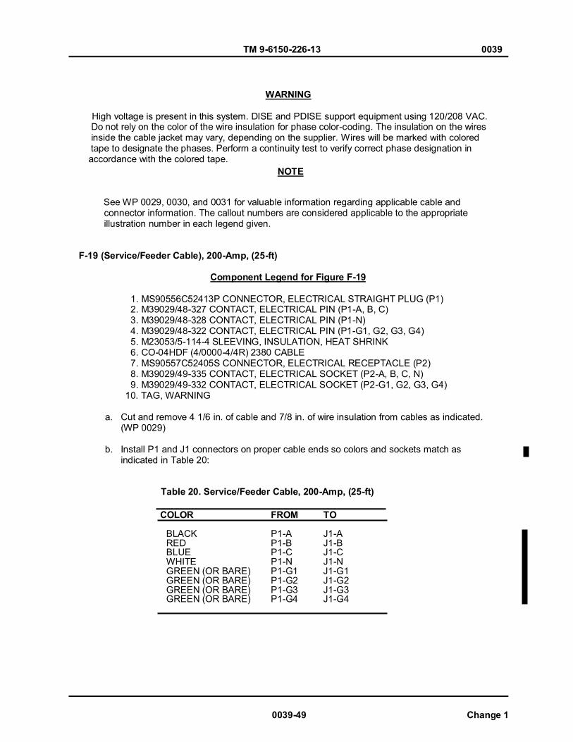
TM 9-6150-226-13 0039
0039-49 Change 1
WARNING
High voltage is present in this system. DISE and PDISE support equipment using 120/208 VAC.
Do not rely on the color of the wire insulation for phase color-coding. The insulation on the wires inside the cable jacket may vary, depending on the supplier. Wires will be marked with colored tape to designate the phases. Perform a continuity test to verify correct phase designation in accordance with the colored tape.
See WP 0029, 0030, and 0031 for valuable information regarding applicable cable and connector information. The callout numbers are considered applicable to the appropriate illustration number in each legend given.
F-19 (Service/Feeder Cable), 200-Amp, (25-ft) Component Legend for Figure F-19
1. MS90556C52413P CONNECTOR, ELECTRICAL STRAIGHT PLUG (P1) 2. M39029/48-327 CONTACT, ELECTRICAL PIN (P1-A, B, C) 3. M39029/48-328 CONTACT, ELECTRICAL PIN (P1-N) 4. M39029/48-322 CONTACT, ELECTRICAL PIN (P1-G1, G2, G3, G4) 5. M23053/5-114-4 SLEEVING, INSULATION, HEAT SHRINK 6. CO-04HDF (4/0000-4/4R) 2380 CABLE 7. MS90557C52405S CONNECTOR, ELECTRICAL RECEPTACLE (P2)
8. M39029/49-335 CONTACT, ELECTRICAL SOCKET (P2-A, B, C, N) 9. M39029/49-332 CONTACT, ELECTRICAL SOCKET (P2-G1, G2, G3, G4)
10. TAG, WARNING
a. Cut and remove 4 1/6 in. of cable and 7/8 in. of wire insulation from cables as indicated. (WP 0029)
b. Install P1 and J1 connectors on proper cable ends so colors and sockets match as indicated in Table 20:
Table 20. Service/Feeder Cable, 200-Amp, (25-ft)
COLOR FROM TO BLACK P1-A J1-A RED P1-B J1-B BLUE P1-C J1-C WHITE P1-N J1-N GREEN (OR BARE) P1-G1 J1-G1 GREEN (OR BARE) P1-G2 J1-G2 GREEN (OR BARE) P1-G3 J1-G3 GREEN (OR BARE) P1-G4 J1-G4
NOTE
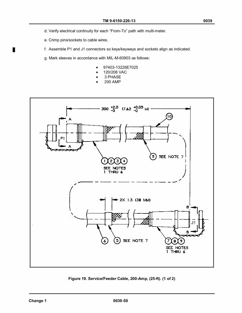
TM 9-6150-226-13 0039
Change 1 0039-50
d. Verify electrical continuity for each “From-To” path with multi-meter. e. Crimp pins/sockets to cable wires. f. Assemble P1 and J1 connectors so keys/keyways and sockets align as indicated. g. Mark sleeves in accordance with MIL-M-60903 as follows:
97403-13226E7025 120/208 VAC 3 PHASE 200 AMP
Figure 19. Service/Feeder Cable, 200-Amp, (25-ft). (1 of 2)

TM 9-6150-226-13 0039
Figure F-19. Service/Feeder Cable, 200-Amp, (25-ft). (2 of 2)
0039-51 Change 1
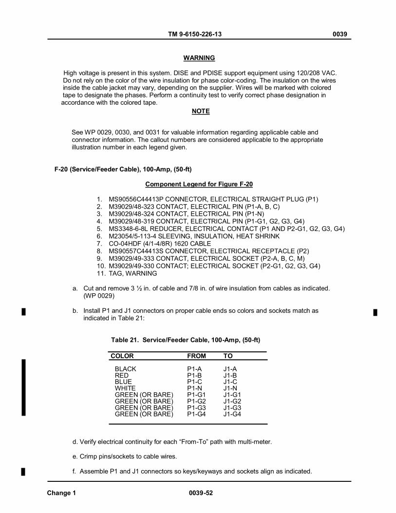
TM 9-6150-226-13 0039
Change 1 0039-52
WARNING
High voltage is present in this system. DISE and PDISE support equipment using 120/208 VAC. Do not rely on the color of the wire insulation for phase color-coding. The insulation on the wires inside the cable jacket may vary, depending on the supplier. Wires will be marked with colored tape to designate the phases. Perform a continuity test to verify correct phase designation in accordance with the colored tape.
See WP 0029, 0030, and 0031 for valuable information regarding applicable cable and connector information. The callout numbers are considered applicable to the appropriate illustration number in each legend given.
F-20 (Service/Feeder Cable), 100-Amp, (50-ft) Component Legend for Figure F-20
1. MS90556C44413P CONNECTOR, ELECTRICAL STRAIGHT PLUG (P1) 2. M39029/48-323 CONTACT, ELECTRICAL PIN (P1-A, B, C) 3. M39029/48-324 CONTACT, ELECTRICAL PIN (P1-N) 4. M39029/48-319 CONTACT, ELECTRICAL PIN (P1-G1, G2, G3, G4) 5. MS3348-6-8L REDUCER, ELECTRICAL CONTACT (P1 AND P2-G1, G2, G3, G4) 6. M23054/5-113-4 SLEEVING, INSULATION, HEAT SHRINK 7. CO-04HDF (4/1-4/8R) 1620 CABLE 8. MS90557C44413S CONNECTOR, ELECTRICAL RECEPTACLE (P2) 9. M39029/49-333 CONTACT, ELECTRICAL SOCKET (P2-A, B, C, M) 10. M39029/49-330 CONTACT; ELECTRICAL SOCKET (P2-G1, G2, G3, G4) 11. TAG, WARNING
a. Cut and remove 3 ½ in. of cable and 7/8 in. of wire insulation from cables as indicated. (WP 0029)
b. Install P1 and J1 connectors on proper cable ends so colors and sockets match as indicated in Table 21:
Table 21. Service/Feeder Cable, 100-Amp, (50-ft)
COLOR FROM TO BLACK P1-A J1-A RED P1-B J1-B BLUE P1-C J1-C WHITE P1-N J1-N GREEN (OR BARE) P1-G1 J1-G1 GREEN (OR BARE) P1-G2 J1-G2 GREEN (OR BARE) P1-G3 J1-G3 GREEN (OR BARE) P1-G4 J1-G4 d. Verify electrical continuity for each “From-To” path with multi-meter.
e. Crimp pins/sockets to cable wires. f. Assemble P1 and J1 connectors so keys/keyways and sockets align as indicated.
NOTE
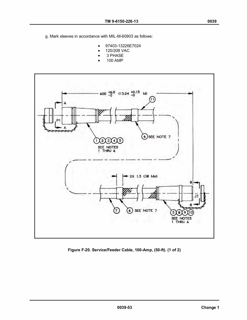
TM 9-6150-226-13 0039
0039-53 Change 1
g. Mark sleeves in accordance with MIL-M-60903 as follows:
97403-13226E7024 120/208 VAC 3 PHASE 100 AMP
Figure F-20. Service/Feeder Cable, 100-Amp, (50-ft). (1 of 2)
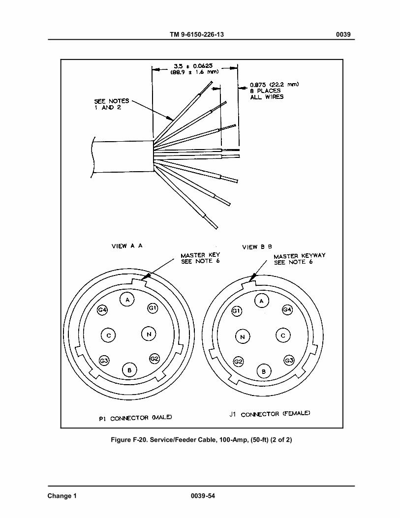
TM 9-6150-226-13 0039
Change 1 0039-54
Figure F-20. Service/Feeder Cable, 100-Amp, (50-ft) (2 of 2)
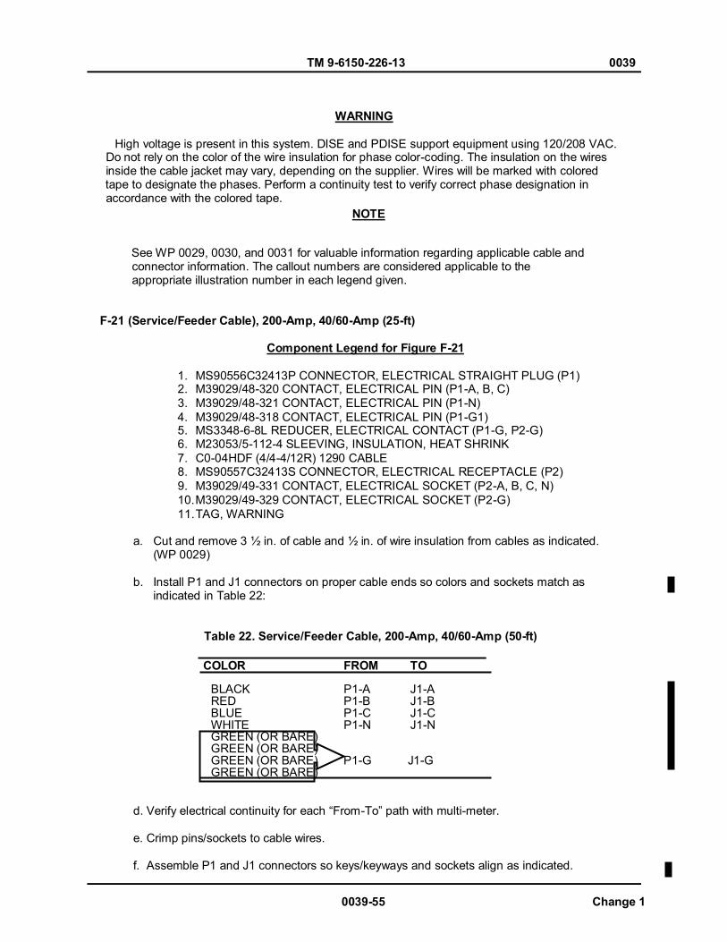
TM 9-6150-226-13 0039
0039-55 Change 1
WARNING
High voltage is present in this system. DISE and PDISE support equipment using 120/208 VAC.
Do not rely on the color of the wire insulation for phase color-coding. The insulation on the wires inside the cable jacket may vary, depending on the supplier. Wires will be marked with colored tape to designate the phases. Perform a continuity test to verify correct phase designation in accordance with the colored tape.
See WP 0029, 0030, and 0031 for valuable information regarding applicable cable and connector information. The callout numbers are considered applicable to the appropriate illustration number in each legend given.
F-21 (Service/Feeder Cable), 200-Amp, 40/60-Amp (25-ft) Component Legend for Figure F-21
1. MS90556C32413P CONNECTOR, ELECTRICAL STRAIGHT PLUG (P1) 2. M39029/48-320 CONTACT, ELECTRICAL PIN (P1-A, B, C) 3. M39029/48-321 CONTACT, ELECTRICAL PIN (P1-N) 4. M39029/48-318 CONTACT, ELECTRICAL PIN (P1-G1) 5. MS3348-6-8L REDUCER, ELECTRICAL CONTACT (P1-G, P2-G) 6. M23053/5-112-4 SLEEVING, INSULATION, HEAT SHRINK 7. C0-04HDF (4/4-4/12R) 1290 CABLE 8. MS90557C32413S CONNECTOR, ELECTRICAL RECEPTACLE (P2) 9. M39029/49-331 CONTACT, ELECTRICAL SOCKET (P2-A, B, C, N) 10. M39029/49-329 CONTACT, ELECTRICAL SOCKET (P2-G) 11. TAG, WARNING
a. Cut and remove 3 ½ in. of cable and ½ in. of wire insulation from cables as indicated. (WP 0029)
b. Install P1 and J1 connectors on proper cable ends so colors and sockets match as indicated in Table 22:
Table 22. Service/Feeder Cable, 200-Amp, 40/60-Amp (50-ft)
COLOR FROM TO BLACK P1-A J1-A RED P1-B J1-B BLUE P1-C J1-C WHITE P1-N J1-N GREEN (OR BARE) GREEN (OR BARE) GREEN (OR BARE) P1-G J1-G GREEN (OR BARE)
d. Verify electrical continuity for each “From-To” path with multi-meter. e. Crimp pins/sockets to cable wires. f. Assemble P1 and J1 connectors so keys/keyways and sockets align as indicated.
NOTE

TM 9-6150-226-13 0039
Change 1 0039-56
g. Mark sleeves in accordance with MIL-M-60903 as follows:
97403-13226E7023-2 120/208 VAC 3 PHASE 40/60 AMP
Figure F-21. Service/Feeder Cable, 200-Amp, 40/60-Amp (50-ft). (1 of 2)

TM 9-6150-226-13 0039
0039-57 Change 1
Figure F-21. Service/Feeder Cable, 200-Amp, 40/60-Amp (50-ft). (2 of 2)

TM 9-6150-226-13 0039
Change 1 0039-58
WARNING
High voltage is present in this system. DISE and PDISE support equipment using 120/208 VAC. Do not rely on the color of the wire insulation for phase color-coding. The insulation on the wires inside the cable jacket may vary, depending on the supplier. Wires will be marked with colored tape to designate the phases. Perform a continuity test to verify correct phase designation in accordance with the colored tape.
See WP 0029, 0030, and 0031 for valuable information regarding applicable cable and connector information. The callout numbers are considered applicable to the appropriate illustration number in each legend given.
F-22 (Service/Feeder Cable), 60-Amp, (100-ft) Component Legend for Figure F-22
1. MS90556C32405P CONNECTOR, ELECTRICAL STRAIGHT PLUG (P1) 2. M39029/48-320 CONTACT, ELECTRICAL PIN (P1-A) 3. M39029/48-321 CONTACT, ELECTRICAL PIN (P1-N) 4. M39029/48-318 CONTACT, ELECTRICAL PIN (P1-G1, G2) 5. MS3348-6-8L REDUCER, ELECTRICAL CONTACT (P1-G, G2) 6. M23053/5-112-4 SLEEVING, INSULATION, HEAT SHRINK 7. CO-02HDF (2/4-2/8R) 1290 CABLE 8. MS90557C32405S CONNECTOR, ELECTRICAL RECEPTACLE (P2) 9. M39029/49-331 CONTACT, ELECTRICAL SOCKET (P2-A, N) 10. M39029/49-329 CONTACT, ELECTRICAL SOCKET (P2-G1, G2) 11. TAG, WARNING
a. Cut and remove 3 in. of cable and 7/8 in. of wire insulation from cables as indicated. (WP 0029)
b. Install P1 and J1 connectors on proper cable ends so colors and sockets match as indicated in Table 23:
Table 23. Service/Feeder Cable, 60-Amp, (100-ft)
COLOR FROM TO BLACK P1-A J1-A WHITE P1-N J1-N GREEN (OR BARE) P1-G1 J1-G1 GREEN (OR BARE) P2-G2 J1-G2
d. Verify electrical continuity for each “From-To” path with multi-meter. e. Crimp pins/sockets to cable wires. f. Assemble P1 and J1 connectors so keys/keyways and sockets align as indicated.
NOTE
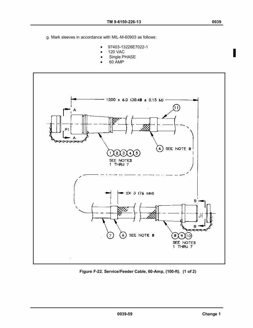
TM 9-6150-226-13 0039
0039-59 Change 1
g. Mark sleeves in accordance with MIL-M-60903 as follows:
97403-13226E7022-1 120 VAC Single PHASE 60 AMP
Figure F-22. Service/Feeder Cable, 60-Amp, (100-ft). (1 of 2)

TM 9-6150-226-13 0039
Change 1 0039-60
Figure F-22. Service/Feeder Cable, 60-Amp, (100-ft). (2 of 2)

TM 9-6150-226-13 0039
0039-61 Change 1
WARNING
High voltage is present in this system. DISE and PDISE support equipment using 120/208 VAC. Do not rely on the color of the wire insulation for phase color-coding. The insulation on the wires inside the cable jacket may vary, depending on the supplier. Wires will be marked with colored tape to designate the phases. Perform a continuity test to verify correct phase designation in accordance with the colored tape.
See WP 0029, 0030, and 0031 for valuable information regarding applicable cable and connector information. The callout numbers are considered applicable to the appropriate illustration number in each legend given.
F-23 (Extension Cable), 20-Amp, (15-ft) Component Legend for Figure F-23
1. MS3456W16-10P CONNECTOR, ELECTRICAL STRAIGHT PLUG (P1) 2. M39029/48-290 CONTACT, ELECTRICAL PIN (P1-A, B, C) 3. MS25042-16D COVER, ELECTRICAL CONNECTOR, STRAIGHT PLUG 4. CO-03MGF (3/12) 0385 CABLE BLACK 5. M23053/5-109-4 SLEEVING, INSULATION, HEAT SHRINK 6. MS3451W16-10S CONNECTOR, ELECTRICAL, RECEPTACLE (P2) 7. MS25043-16D COVER, ELECTRICAL, CONNECTOR, ELECTRICAL RECEPTACLE 8. M39020/30-219 CONTACT, ELECTRICAL SOCKET (P2-A, B, C)
a. Cut and remove ½ in. of cable and 3/8 in. of wire insulation from cables as indicated. (WP 0029)
b. Install P1 and J2 connectors on proper cable ends so colors and sockets match as indicated in Table 24:
Table 24. Extension Cable, 20-Amp, (15-ft)
COLOR FROM TO BLACK P1-A J2-A WHITE P1-B J2-B GREEN P1-C J2-C
d. Verify electrical continuity for each “From-To” path with multi-meter. e. Crimp pins/sockets to cable wires. f. Assemble P1 and J2 connectors so keys/keyways and pins/sockets align as indicated. g. Mark sleeves in accordance with MIL-M-60903 as follows:
97403-13226E7032-2 120 VAC Single PHASE 20 AMP
NOTE
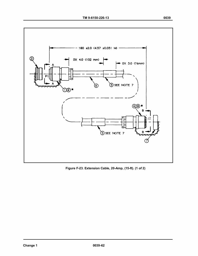
TM 9-6150-226-13 0039
Change 1 0039-62
Figure F-23. Extension Cable, 20-Amp, (15-ft). (1 of 2)

TM 9-6150-226-13 0039
0039-63 Change 1
Figure F-23. Extension Cable, 20-Amp, (15-ft). (2 of 2)
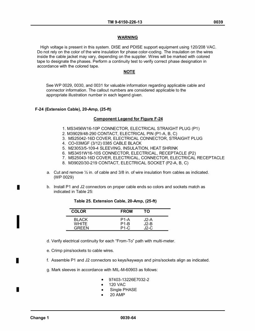
TM 9-6150-226-13 0039
Change 1 0039-64
WARNING
High voltage is present in this system. DISE and PDISE support equipment using 120/208 VAC. Do not rely on the color of the wire insulation for phase color-coding. The insulation on the wires inside the cable jacket may vary, depending on the supplier. Wires will be marked with colored tape to designate the phases. Perform a continuity test to verify correct phase designation in accordance with the colored tape.
See WP 0029, 0030, and 0031 for valuable information regarding applicable cable and connector information. The callout numbers are considered applicable to the appropriate illustration number in each legend given.
F-24 (Extension Cable), 20-Amp, (25-ft) Component Legend for Figure F-24
1. MS3456W16-10P CONNECTOR, ELECTRICAL STRAIGHT PLUG (P1) 2. M39029/48-290 CONTACT, ELECTRICAL PIN (P1-A, B, C) 3. MS25042-16D COVER, ELECTRICAL CONNECTOR, STRAIGHT PLUG 4. CO-03MGF (3/12) 0385 CABLE BLACK 5. M23053/5-109-4 SLEEVING, INSULATION, HEAT SHRINK 6. MS3451W16-10S CONNECTOR, ELECTRICAL, RECEPTACLE (P2) 7. MS25043-16D COVER, ELECTRICAL, CONNECTOR, ELECTRICAL RECEPTACLE 8. M39020/30-219 CONTACT, ELECTRICAL SOCKET (P2-A, B, C)
a. Cut and remove ½ in. of cable and 3/8 in. of wire insulation from cables as indicated. (WP 0029)
b. Install P1 and J2 connectors on proper cable ends so colors and sockets match as indicated in Table 25:
Table 25. Extension Cable, 20-Amp, (25-ft)
COLOR FROM TO BLACK P1-A J2-A WHITE P1-B J2-B GREEN P1-C J2-C
d. Verify electrical continuity for each “From-To” path with multi-meter. e. Crimp pins/sockets to cable wires. f. Assemble P1 and J2 connectors so keys/keyways and pins/sockets align as indicated. g. Mark sleeves in accordance with MIL-M-60903 as follows:
97403-13226E7032-2 120 VAC Single PHASE 20 AMP
NOTE
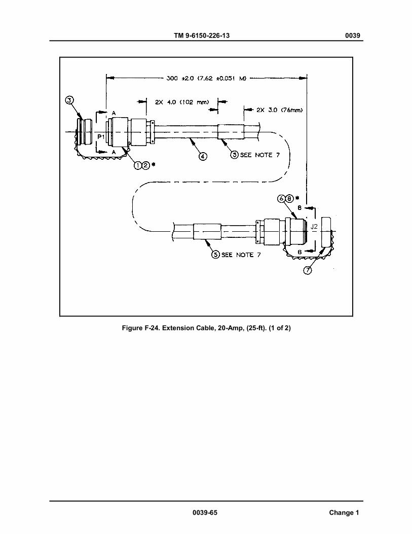
TM 9-6150-226-13 0039
0039-65 Change 1
Figure F-24. Extension Cable, 20-Amp, (25-ft). (1 of 2)

TM 9-6150-226-13 0039
Change 1 0039-66
Figure F-24. Extension Cable, 20-Amp, (25-ft). (2 of 2)
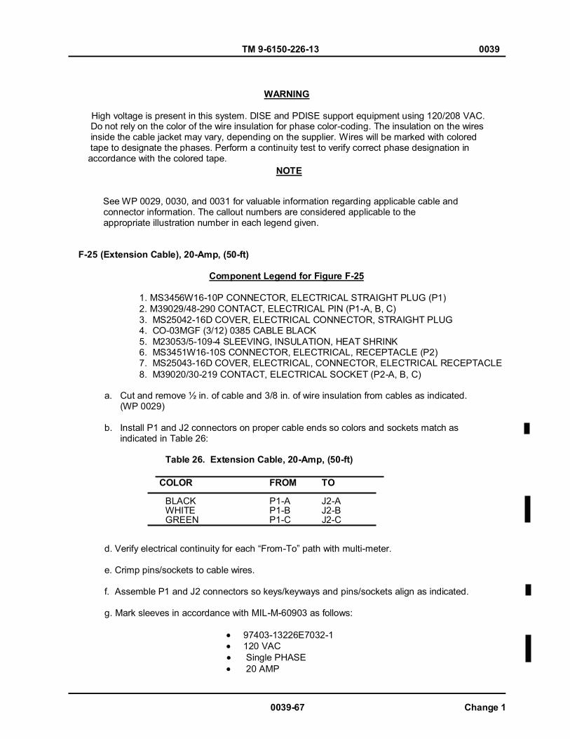
TM 9-6150-226-13 0039
0039-67 Change 1
WARNING
High voltage is present in this system. DISE and PDISE support equipment using 120/208 VAC. Do not rely on the color of the wire insulation for phase color-coding. The insulation on the wires inside the cable jacket may vary, depending on the supplier. Wires will be marked with colored tape to designate the phases. Perform a continuity test to verify correct phase designation in accordance with the colored tape.
See WP 0029, 0030, and 0031 for valuable information regarding applicable cable and connector information. The callout numbers are considered applicable to the appropriate illustration number in each legend given.
F-25 (Extension Cable), 20-Amp, (50-ft) Component Legend for Figure F-25
1. MS3456W16-10P CONNECTOR, ELECTRICAL STRAIGHT PLUG (P1) 2. M39029/48-290 CONTACT, ELECTRICAL PIN (P1-A, B, C) 3. MS25042-16D COVER, ELECTRICAL CONNECTOR, STRAIGHT PLUG 4. CO-03MGF (3/12) 0385 CABLE BLACK 5. M23053/5-109-4 SLEEVING, INSULATION, HEAT SHRINK 6. MS3451W16-10S CONNECTOR, ELECTRICAL, RECEPTACLE (P2) 7. MS25043-16D COVER, ELECTRICAL, CONNECTOR, ELECTRICAL RECEPTACLE 8. M39020/30-219 CONTACT, ELECTRICAL SOCKET (P2-A, B, C)
a. Cut and remove ½ in. of cable and 3/8 in. of wire insulation from cables as indicated. (WP 0029)
b. Install P1 and J2 connectors on proper cable ends so colors and sockets match as indicated in Table 26:
Table 26. Extension Cable, 20-Amp, (50-ft)
COLOR FROM TO BLACK P1-A J2-A WHITE P1-B J2-B GREEN P1-C J2-C
d. Verify electrical continuity for each “From-To” path with multi-meter. e. Crimp pins/sockets to cable wires. f. Assemble P1 and J2 connectors so keys/keyways and pins/sockets align as indicated. g. Mark sleeves in accordance with MIL-M-60903 as follows:
97403-13226E7032-1 120 VAC Single PHASE 20 AMP
NOTE

TM 9-6150-226-13 0039
Change 1 0039-68
Figure F-25. Extension Cable, 20-Amp, (50-ft). (1 of 2)

TM 9-6150-226-13 0039
0039-69 Change 1
Figure F-25. Extension Cable, 20-Amp, (50-ft). (2 of 2)
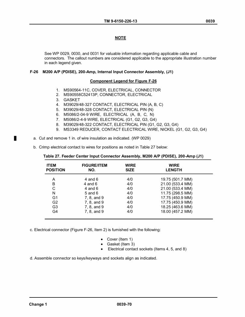
TM 9-6150-226-13 0039
Change 1 0039-70
See WP 0029, 0030, and 0031 for valuable information regarding applicable cable and connectors. The callout numbers are considered applicable to the appropriate illustration number in each legend given. F-26 M200 A/P (PDISE), 200-Amp, Internal Input Connector Assembly, (J1)
Component Legend for Figure F-26
1. MS90564-11C, COVER, ELECTRICAL, CONNECTOR 2. MS90558C52413P, CONNECTOR, ELECTRICAL 3. GASKET 4. M39029/48-327 CONTACT, ELECTRICAL PIN (A, B, C) 5. M39029/48-328 CONTACT, ELECTRICAL PIN (N) 6. M5086/2-04-9 WIRE, ELECTRICAL (A, B, C, N) 7. M5086/2-4-9 WIRE, ELECTRICAL (G1, G2, G3, G4) 8. M39029/48-322 CONTACT, ELECTRICAL PIN (G1, G2, G3, G4) 9. MS3349 REDUCER, CONTACT ELECTRICAL WIRE, NICKEL (G1, G2, G3, G4)
a. Cut and remove 1 in. of wire insulation as indicated. (WP 0029) b. Crimp electrical contact to wires for positions as noted in Table 27 below:
Table 27. Feeder Center Input Connector Assembly, M200 A/P (PDISE), 200-Amp (J1) ITEM FIGURE/ITEM WIRE WIRE
POSITION NO. SIZE LENGTH
A 4 and 6 B 4 and 6 C 4 and 6 N 5 and 6 G1 7, 8, and 9 G2 7, 8, and 9 G3 7, 8, and 9 G4 7, 8, and 9
4/0 4/0 4/0 4/0 4/0 4/0 4/0 4/0
19.75 (501.7 MM) 21.00 (533.4 MM) 21.00 (533.4 MM) 11.75 (298.5 MM) 17.75 (450.9 MM) 17.75 (450.9 MM) 18.25 (463.6 MM) 18.00 (457.2 MM)
c. Electrical connector (Figure F-26, Item 2) is furnished with the following:
Cover (Item 1) Gasket (Item 3) Electrical contact sockets (Items 4, 5, and 8)
d. Assemble connector so keys/keyways and sockets align as indicated.
NOTE
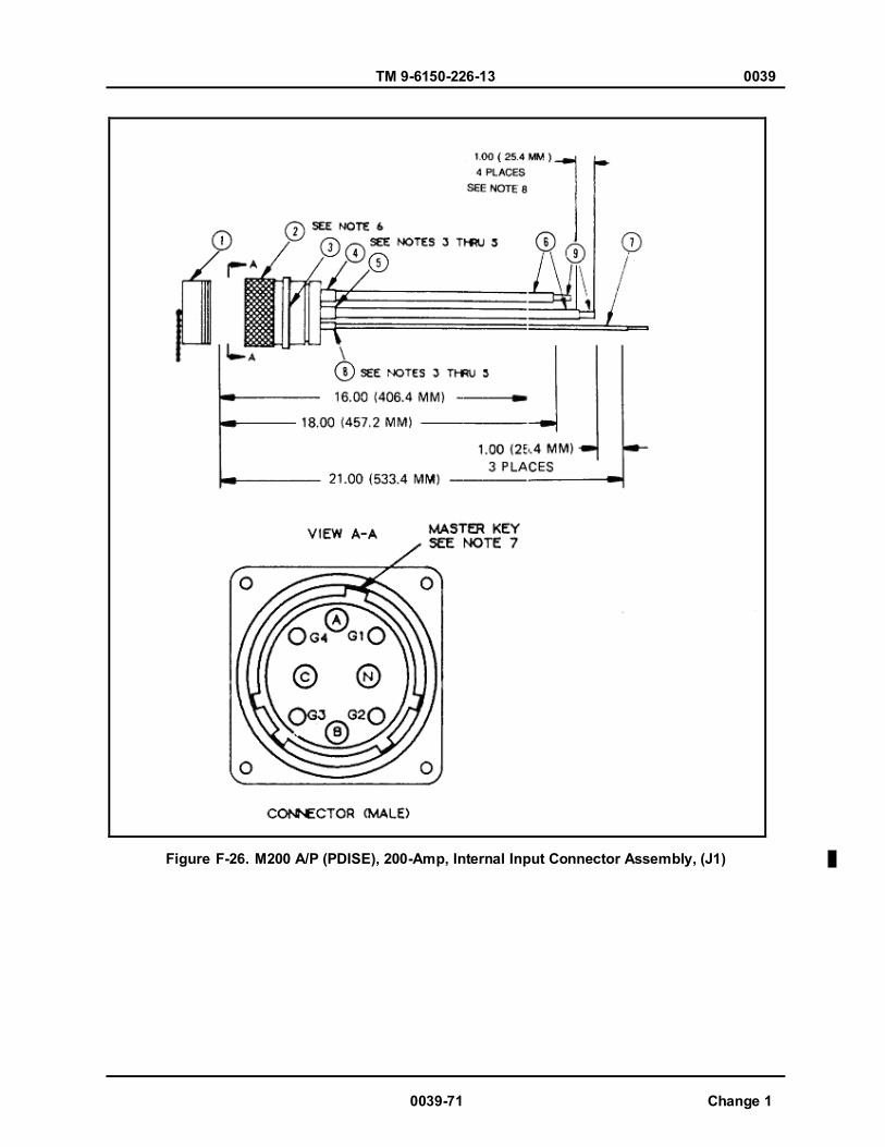
TM 9-6150-226-13 0039
0039-71 Change 1
Figure F-26. M200 A/P (PDISE), 200-Amp, Internal Input Connector Assembly, (J1)

TM 9-6150-226-13 0039
Change 1 0039-72
See WP 0029, 0030, and 0031 for valuable information regarding applicable cable and connectors. The callout numbers are considered applicable to the appropriate illustration number in each legend given. F-27 M100 A/P (PDISE), 100-Amp, Input Connector, (P1)
Component Legend for Figure F-27
1. MS90564-7C COVER, ELECTRICAL CONNECTOR 2. MS9055844413P CONNECTOR, ELECTRICAL 3. GASKET 4. M39029/48-323 CONTACT, ELECTRICAL PIN (A, B, C) 5. M39029/48-324 CONTACT, ELECTRICAL PIN (N) 6. M5086/2-1-9 WIRE, ELECTRICAL (A, B, C, N) 7. M5086/2-6-9 WIRE, ELECTRICAL (G1, G2, G3, G4) 8. M39029/48-319 CONTACT, ELECTRICAL PIN (G1, G2, G3, G4)
a. Cut and remove 1 in. of wire insulation as indicated. (WP 0029) b. Crimp electrical contact to wires for positions as noted in Table 28 below: Table 28. Feeder Center Input Connector, M100 A/P (PDISE), 100-Amp (P1) ITEM FIGURE/ITEM WIRE WIRE
POSITION NO. SIZE LENGTH
A 4 AND 6 1 24.50 (633.3 MM) B 4 AND 6 1 25.00 (635.0 MM) C 4 AND 6 1 24.75 (628.7 MM) N 5 AND 6 1 7.50 (190.5 MM) G1 7, 8, AND 9 6 11.50 (292.1 MM) G2 7, 8, AND 9 6 11.62 (295.1 MM) G3 7, 8, AND 9 6 10.00 (254.0 MM) G4 7, 8, AND 9 6 10.75 (273.1 MM)
c. Electrical connector (Figure F-27, Item 2) is furnished with the following:
Cover (Item 1) Gasket (Item 3) Electrical contact sockets (Items 4, 5, and 8)
d. Assemble connector so keys/keyways and sockets align as indicated.
NOTE
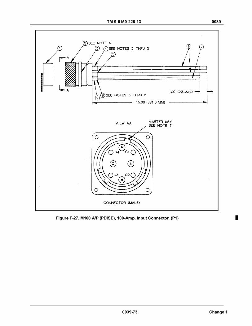
TM 9-6150-226-13 0039
0039-73 Change 1
Figure F-27. M100 A/P (PDISE), 100-Amp, Input Connector, (P1)
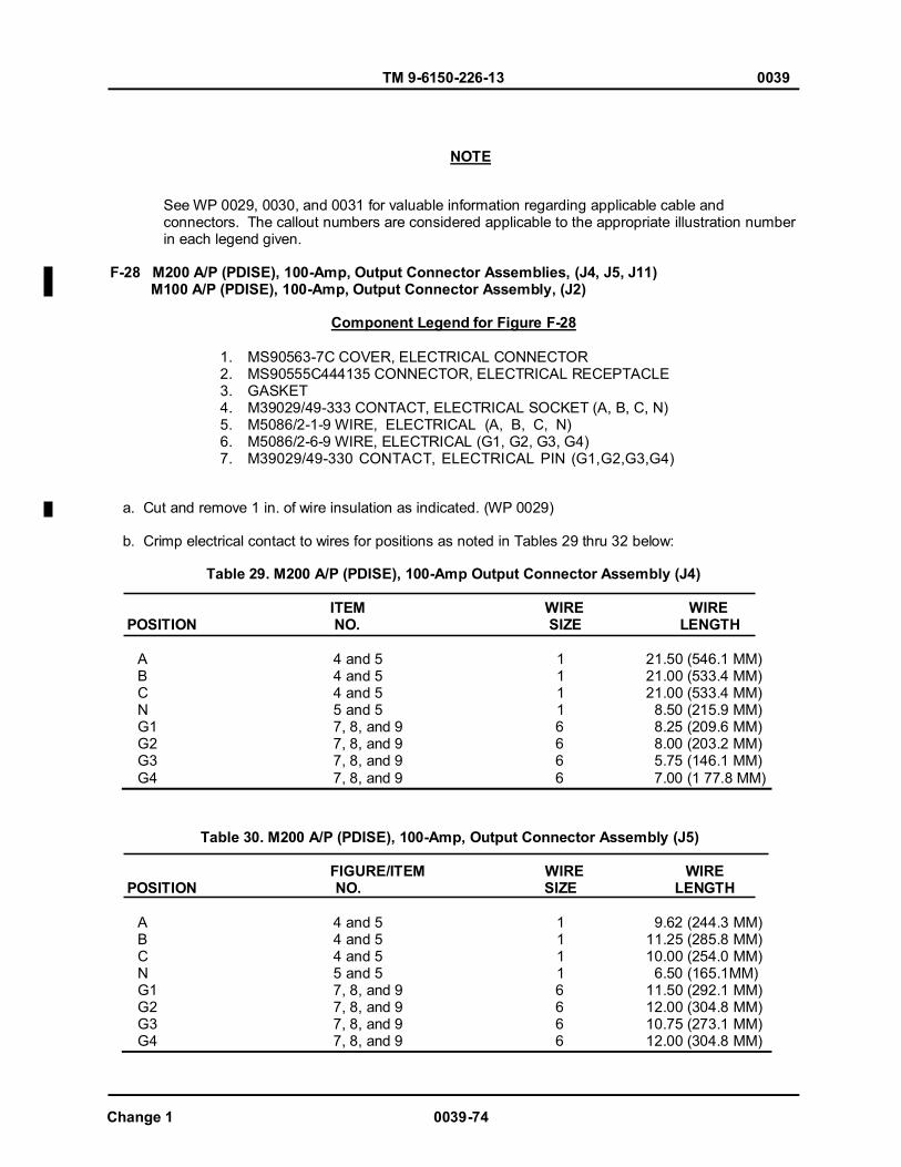
TM 9-6150-226-13 0039
Change 1 0039-74
See WP 0029, 0030, and 0031 for valuable information regarding applicable cable and connectors. The callout numbers are considered applicable to the appropriate illustration number in each legend given. F-28 M200 A/P (PDISE), 100-Amp, Output Connector Assemblies, (J4, J5, J11) M100 A/P (PDISE), 100-Amp, Output Connector Assembly, (J2)
Component Legend for Figure F-28
1. MS90563-7C COVER, ELECTRICAL CONNECTOR 2. MS90555C444135 CONNECTOR, ELECTRICAL RECEPTACLE 3. GASKET 4. M39029/49-333 CONTACT, ELECTRICAL SOCKET (A, B, C, N) 5. M5086/2-1-9 WIRE, ELECTRICAL (A, B, C, N) 6. M5086/2-6-9 WIRE, ELECTRICAL (G1, G2, G3, G4) 7. M39029/49-330 CONTACT, ELECTRICAL PIN (G1,G2,G3,G4)
a. Cut and remove 1 in. of wire insulation as indicated. (WP 0029) b. Crimp electrical contact to wires for positions as noted in Tables 29 thru 32 below:
Table 29. M200 A/P (PDISE), 100-Amp Output Connector Assembly (J4) ITEM WIRE WIRE
POSITION NO. SIZE LENGTH
A 4 and 5 1 21.50 (546.1 MM) B 4 and 5 1 21.00 (533.4 MM) C 4 and 5 1 21.00 (533.4 MM) N 5 and 5 1 8.50 (215.9 MM) G1 7, 8, and 9 6 8.25 (209.6 MM) G2 7, 8, and 9 6 8.00 (203.2 MM) G3 7, 8, and 9 6 5.75 (146.1 MM) G4 7, 8, and 9 6 7.00 (1 77.8 MM)
Table 30. M200 A/P (PDISE), 100-Amp, Output Connector Assembly (J5)
FIGURE/ITEM WIRE WIRE POSITION NO. SIZE LENGTH
A 4 and 5 1 9.62 (244.3 MM) B 4 and 5 1 11.25 (285.8 MM) C 4 and 5 1 10.00 (254.0 MM) N 5 and 5 1 6.50 (165.1MM) G1 7, 8, and 9 6 11.50 (292.1 MM) G2 7, 8, and 9 6 12.00 (304.8 MM) G3 7, 8, and 9 6 10.75 (273.1 MM) G4 7, 8, and 9 6 12.00 (304.8 MM)
NOTE
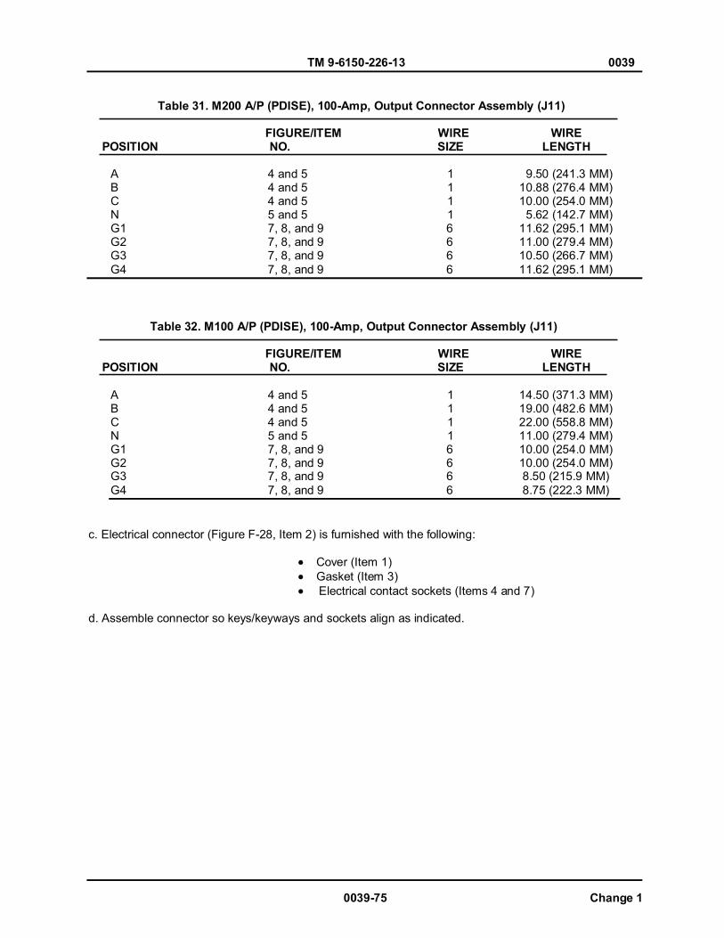
TM 9-6150-226-13 0039
0039-75 Change 1
Table 31. M200 A/P (PDISE), 100-Amp, Output Connector Assembly (J11)
FIGURE/ITEM WIRE WIRE POSITION NO. SIZE LENGTH
A 4 and 5 1 9.50 (241.3 MM) B 4 and 5 1 10.88 (276.4 MM) C 4 and 5 1 10.00 (254.0 MM) N 5 and 5 1 5.62 (142.7 MM) G1 7, 8, and 9 6 11.62 (295.1 MM) G2 7, 8, and 9 6 11.00 (279.4 MM) G3 7, 8, and 9 6 10.50 (266.7 MM) G4 7, 8, and 9 6 11.62 (295.1 MM)
Table 32. M100 A/P (PDISE), 100-Amp, Output Connector Assembly (J11)
FIGURE/ITEM WIRE WIRE POSITION NO. SIZE LENGTH
A 4 and 5 1 14.50 (371.3 MM) B 4 and 5 1 19.00 (482.6 MM) C 4 and 5 1 22.00 (558.8 MM) N 5 and 5 1 11.00 (279.4 MM) G1 7, 8, and 9 6 10.00 (254.0 MM) G2 7, 8, and 9 6 10.00 (254.0 MM) G3 7, 8, and 9 6 8.50 (215.9 MM) G4 7, 8, and 9 6 8.75 (222.3 MM)
c. Electrical connector (Figure F-28, Item 2) is furnished with the following:
Cover (Item 1) Gasket (Item 3) Electrical contact sockets (Items 4 and 7)
d. Assemble connector so keys/keyways and sockets align as indicated.

TM 9-6150-226-13 0039
Figure F-28. M200/100, (PDISE) 100-Amp, Output Connector Assembly.
Change 1 0039-76
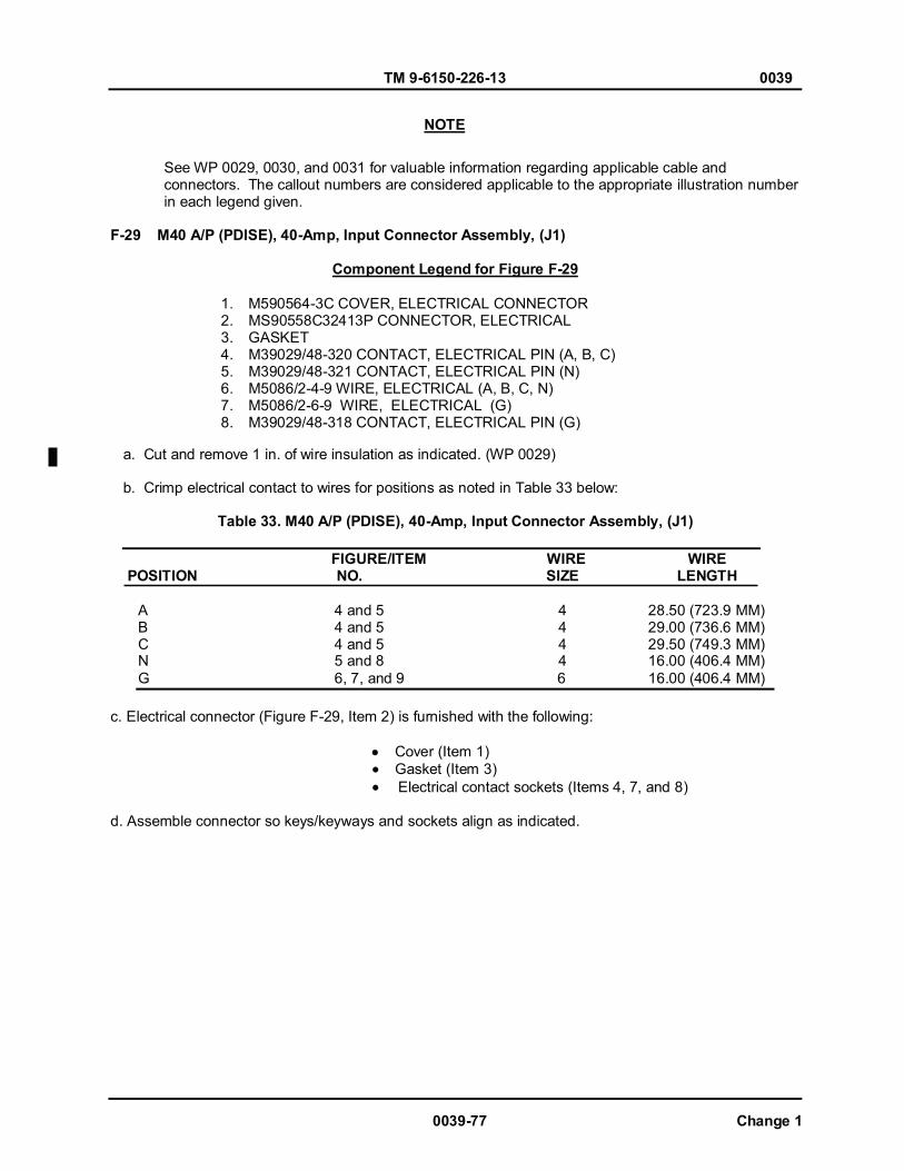
TM 9-6150-226-13 0039
0039-77 Change 1
See WP 0029, 0030, and 0031 for valuable information regarding applicable cable and connectors. The callout numbers are considered applicable to the appropriate illustration number in each legend given. F-29 M40 A/P (PDISE), 40-Amp, Input Connector Assembly, (J1)
Component Legend for Figure F-29
1. M590564-3C COVER, ELECTRICAL CONNECTOR 2. MS90558C32413P CONNECTOR, ELECTRICAL 3. GASKET 4. M39029/48-320 CONTACT, ELECTRICAL PIN (A, B, C) 5. M39029/48-321 CONTACT, ELECTRICAL PIN (N) 6. M5086/2-4-9 WIRE, ELECTRICAL (A, B, C, N) 7. M5086/2-6-9 WIRE, ELECTRICAL (G) 8. M39029/48-318 CONTACT, ELECTRICAL PIN (G)
a. Cut and remove 1 in. of wire insulation as indicated. (WP 0029) b. Crimp electrical contact to wires for positions as noted in Table 33 below:
Table 33. M40 A/P (PDISE), 40-Amp, Input Connector Assembly, (J1)
FIGURE/ITEM WIRE WIRE POSITION NO. SIZE LENGTH
A 4 and 5 4 28.50 (723.9 MM) B 4 and 5 4 29.00 (736.6 MM) C 4 and 5 4 29.50 (749.3 MM) N 5 and 8 4 16.00 (406.4 MM) G 6, 7, and 9 6 16.00 (406.4 MM)
c. Electrical connector (Figure F-29, Item 2) is furnished with the following:
Cover (Item 1) Gasket (Item 3) Electrical contact sockets (Items 4, 7, and 8)
d. Assemble connector so keys/keyways and sockets align as indicated.
NOTE
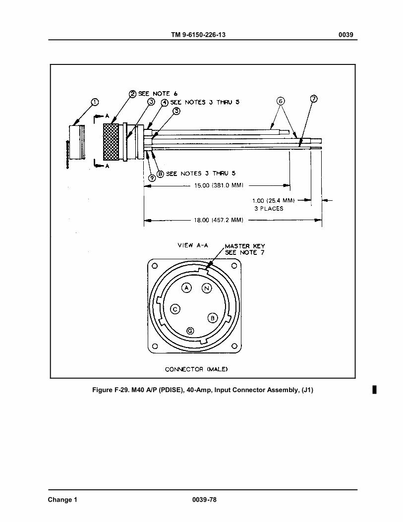
TM 9-6150-226-13 0039
Change 1 0039-78
Figure F-29. M40 A/P (PDISE), 40-Amp, Input Connector Assembly, (J1)
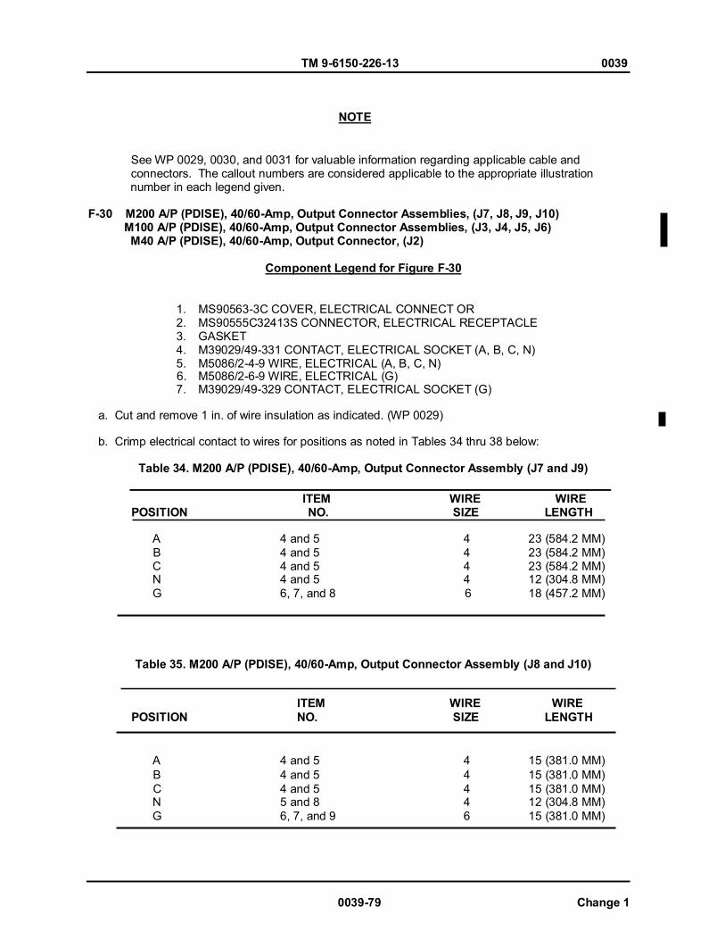
TM 9-6150-226-13 0039
0039-79 Change 1
See WP 0029, 0030, and 0031 for valuable information regarding applicable cable and connectors. The callout numbers are considered applicable to the appropriate illustration number in each legend given. F-30 M200 A/P (PDISE), 40/60-Amp, Output Connector Assemblies, (J7, J8, J9, J10) M100 A/P (PDISE), 40/60-Amp, Output Connector Assemblies, (J3, J4, J5, J6) M40 A/P (PDISE), 40/60-Amp, Output Connector, (J2)
Component Legend for Figure F-30
1. MS90563-3C COVER, ELECTRICAL CONNECT OR 2. MS90555C32413S CONNECTOR, ELECTRICAL RECEPTACLE 3. GASKET 4. M39029/49-331 CONTACT, ELECTRICAL SOCKET (A, B, C, N) 5. M5086/2-4-9 WlRE, ELECTRICAL (A, B, C, N)
6. M5086/2-6-9 WlRE, ELECTRICAL (G) 7. M39029/49-329 CONTACT, ELECTRICAL SOCKET (G)
a. Cut and remove 1 in. of wire insulation as indicated. (WP 0029) b. Crimp electrical contact to wires for positions as noted in Tables 34 thru 38 below:
Table 34. M200 A/P (PDISE), 40/60-Amp, Output Connector Assembly (J7 and J9)
ITEM WIRE WIRE POSITION NO. SIZE LENGTH
A 4 and 5 4 23 (584.2 MM) B 4 and 5 4 23 (584.2 MM) C 4 and 5 4 23 (584.2 MM) N 4 and 5 4 12 (304.8 MM) G 6, 7, and 8 6 18 (457.2 MM)
Table 35. M200 A/P (PDISE), 40/60-Amp, Output Connector Assembly (J8 and J10)
ITEM WIRE WIRE POSITION NO. SIZE LENGTH
A 4 and 5 4 15 (381.0 MM) B 4 and 5 4 15 (381.0 MM) C 4 and 5 4 15 (381.0 MM) N 5 and 8 4 12 (304.8 MM) G 6, 7, and 9 6 15 (381.0 MM)
NOTE

TM 9-6150-226-13 0039
Change 1 0039-80
Table 36. M100 A/P (PDISE), 40/60-Amp, Output Connector Assembly (J3 and J5)
ITEM WIRE WIRE
POSITION NO. SIZE LENGTH
A 4 and 5 4 25 (635.0 MM) B 4 and 5 4 25 (635.0 MM) C 4 and 5 4 25 (635.0 MM) N 5 and 8 4 12 (304.8 MM) G 6, 7, and 9 6 15 (381.0 MM)
Table 37. M100 A/P (PDISE), 40/60-Amp, Output Connector Assembly (J4 and J6) ITEM WIRE WIRE
POSITION NO. SIZE LENGTH
A 4 and 5 4 14 (355.6 MM) B 4 and 5 4 14 (355.6 MM) C 4 and 5 4 14 (355.6 MM) N 5 and 8 4 14 (355.6 MM) G 6, 7, and 9 6 15 (381.0 MM)
Table 38. M40 A/P (PDISE), 40/60-Amp, Output Connector Assembly (J2)
ITEM WIRE WIRE POSITION NO. SIZE LENGTH
A 4 and 5 4 18 (457.2 MM) B 4 and 5 4 18 (457.2 MM) C 4 and 5 4 18 (457.2 MM) N 5 and 8 4 18 (457.2 MM) G 6, 7, and 9 6 18 (457.2 MM)
c. Electrical connector (Figure F-30, Item 2) is furnished with the following:
Cover (Item 1) Gasket (Item 3) Electrical contact sockets (Items 4 and 7)
d. Assemble connector so keys/keyways and sockets align as indicated.
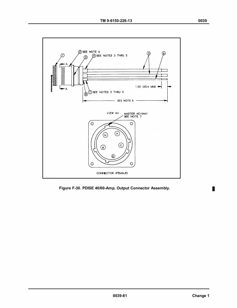
TM 9-6150-226-13 0039
0039-81 Change 1
Figure F-30. PDISE 40/60-Amp, Output Connector Assembly.
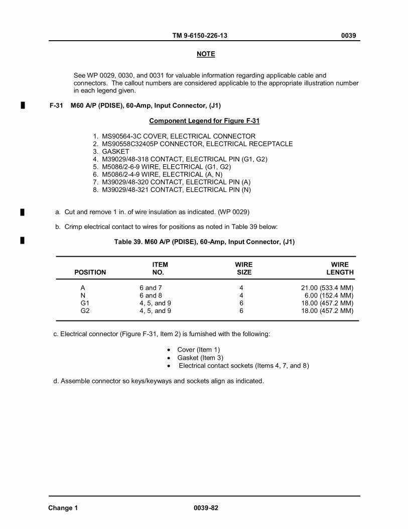
TM 9-6150-226-13 0039
See WP 0029, 0030, and 0031 for valuable information regarding applicable cable and connectors. The callout numbers are considered applicable to the appropriate illustration number in each legend given. F-31 M60 A/P (PDISE), 60-Amp, Input Connector, (J1)
Component Legend for Figure F-31
1. MS90564-3C COVER, ELECTRICAL CONNECTOR 2. MS90558C32405P CONNECTOR, ELECTRICAL RECEPTACLE 3. GASKET 4. M39029/48-318 CONTACT, ELECTRICAL PIN (G1, G2) 5. M5086/2-6-9 WIRE, ELECTRICAL (G1, G2) 6. M5086/2-4-9 WIRE, ELECTRICAL (A, N) 7. M39029/48-320 CONTACT, ELECTRICAL PIN (A) 8. M39029/48-321 CONTACT, ELECTRICAL PIN (N)
a. Cut and remove 1 in. of wire insulation as indicated. (WP 0029) b. Crimp electrical contact to wires for positions as noted in Table 39 below:
Table 39. M60 A/P (PDISE), 60-Amp, Input Connector, (J1)
ITEM WIRE WIRE POSITION NO. SIZE LENGTH
A 6 and 7 4 21.00 (533.4 MM) N 6 and 8 4 6.00 (152.4 MM) G1 4, 5, and 9 6 18.00 (457.2 MM) G2 4, 5, and 9 6 18.00 (457.2 MM)
c. Electrical connector (Figure F-31, Item 2) is furnished with the following:
Cover (Item 1) Gasket (Item 3) Electrical contact sockets (Items 4, 7, and 8)
d. Assemble connector so keys/keyways and sockets align as indicated.
NOTE
Change 1 0039-82
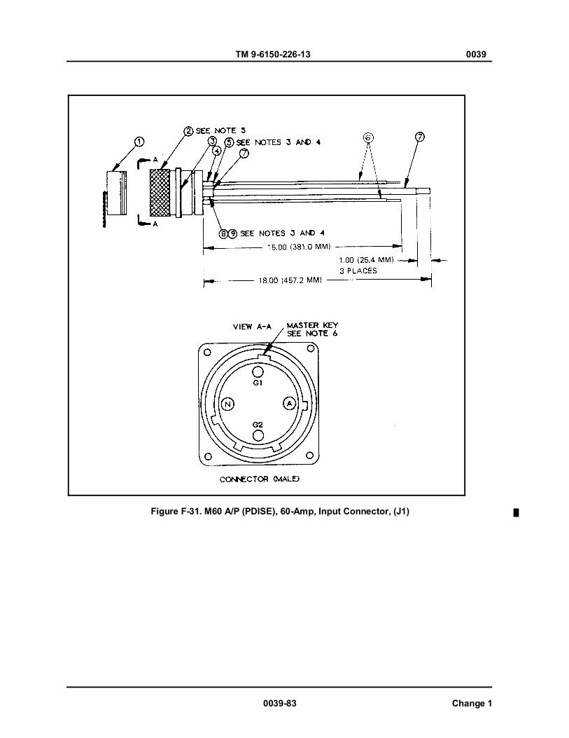
TM 9-6150-226-13 0039
0039-83 Change 1
Figure F-31. M60 A/P (PDISE), 60-Amp, Input Connector, (J1)

TM 9-6150-226-13 0039
Change 1 0039-84
See WP 0029, 0030, and 0031 for valuable information regarding applicable cable and connectors. The callout numbers are considered applicable to the appropriate illustration number in each legend given. F-32 M60 A/P (PDISE), 60-Amp, Output Connector Assembly, (J2)
Component Legend for Figure F-32
1. MS90564-3C COVER, ELECTRICAL CONNECTOR 2. MS90558C32405P CONNECTOR, ELECTRICAL RECEPTACLE 3. GASKET 4. M39029/49-329 CONTACT, ELECTRICAL PIN (G1, G2) 5. M5086/2-6-9 WIRE, ELECTRICAL (G1, G2) 6. M5086/2-4-9 WIRE, ELECTRICAL (A, N) 7. M39029/49-331 CONTACT, ELECTRICAL PIN (A, N)
a. Cut and remove 1 in. of wire insulation as indicated. (WP 0029) b. Crimp electrical contact to wires for positions as noted in Table 40 below:
Table 40. M60 A/P (PDISE), 60-Amp, Output Connector Assembly, (J2)
ITEM WIRE WIRE POSITION NO. SIZE LENGTH
A 7 and 8 4 14.50 (368.3 MM) N 7 and 8 4 14.00 (355.6 MM) G1 4, 5, and 6 6 6.00 (152.4 MM) G2 4, 5, and 6 6 6.00 (152.4 MM)
c. Electrical connector (Figure F-32, Item 2) is furnished with the following:
Cover (Item 1) Gasket (Item 3) Electrical contact sockets (Items 5 and 8)
d. Assemble connector so keys/keyways and sockets align as indicated.
NOTE
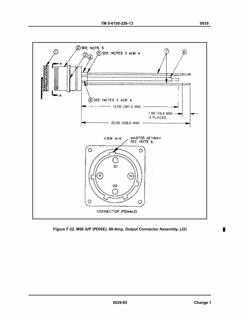
TM 9-6150-226-13 0039
0039-85 Change 1
Figure F-32. M60 A/P (PDISE), 60-Amp, Output Connector Assembly, (J2)
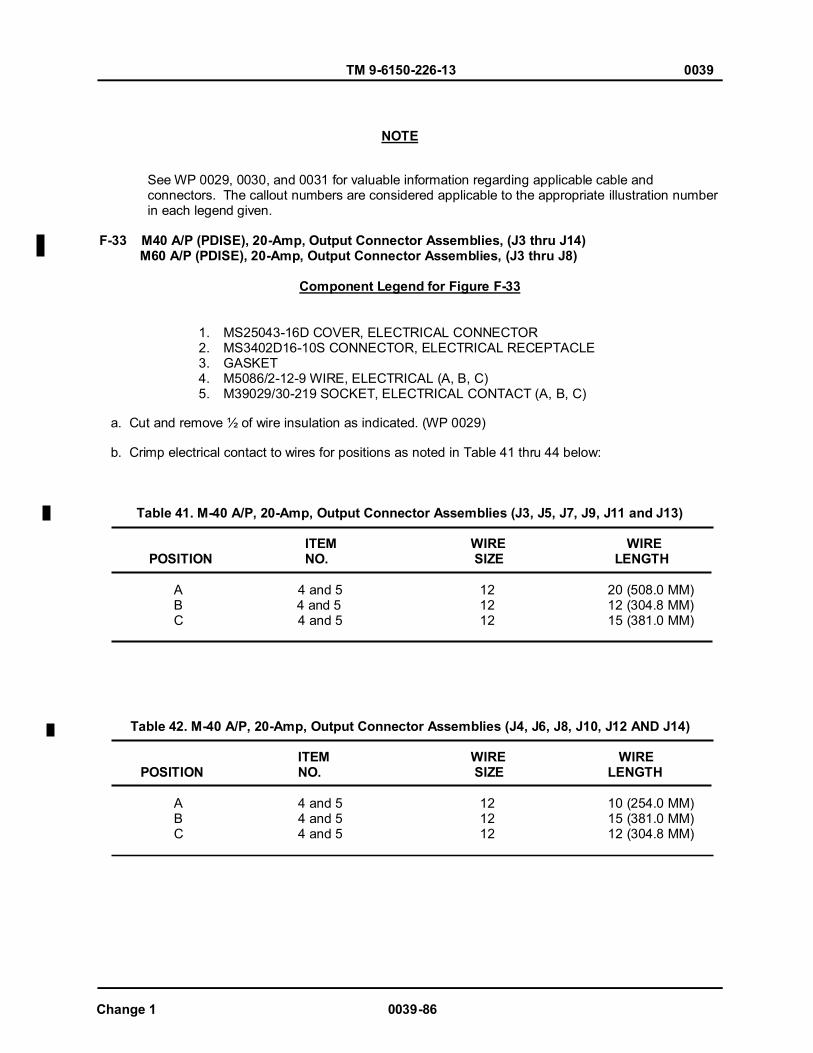
TM 9-6150-226-13 0039
See WP 0029, 0030, and 0031 for valuable information regarding applicable cable and connectors. The callout numbers are considered applicable to the appropriate illustration number in each legend given. F-33 M40 A/P (PDISE), 20-Amp, Output Connector Assemblies, (J3 thru J14) M60 A/P (PDISE), 20-Amp, Output Connector Assemblies, (J3 thru J8)
Component Legend for Figure F-33
1. MS25043-16D COVER, ELECTRICAL CONNECTOR 2. MS3402D16-10S CONNECTOR, ELECTRICAL RECEPTACLE 3. GASKET 4. M5086/2-12-9 WIRE, ELECTRICAL (A, B, C) 5. M39029/30-219 SOCKET, ELECTRICAL CONTACT (A, B, C)
a. Cut and remove ½ of wire insulation as indicated. (WP 0029) b. Crimp electrical contact to wires for positions as noted in Table 41 thru 44 below:
Table 41. M-40 A/P, 20-Amp, Output Connector Assemblies (J3, J5, J7, J9, J11 and J13)
ITEM WIRE WIRE POSITION NO. SIZE LENGTH
A 4 and 5 12 20 (508.0 MM) B 4 and 5 12 12 (304.8 MM) C 4 and 5 12 15 (381.0 MM)
Table 42. M-40 A/P, 20-Amp, Output Connector Assemblies (J4, J6, J8, J10, J12 AND J14)
ITEM WIRE WIRE POSITION NO. SIZE LENGTH
A 4 and 5 12 10 (254.0 MM) B 4 and 5 12 15 (381.0 MM) C 4 and 5 12 12 (304.8 MM)
NOTE
Change 1 0039-86
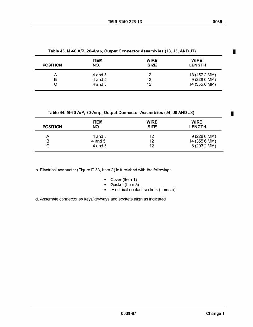
TM 9-6150-226-13 0039
0039-87 Change 1
Table 43. M-60 A/P, 20-Amp, Output Connector Assemblies (J3, J5, AND J7)
ITEM WIRE WIRE POSITION NO. SIZE LENGTH
A 4 and 5 12 18 (457.2 MM) B 4 and 5 12 9 (228.6 MM) C 4 and 5 12 14 (355.6 MM)
Table 44. M-60 A/P, 20-Amp, Output Connector Assemblies (J4, J6 AND J8) ITEM WIRE WIRE
POSITION NO. SIZE LENGTH
A 4 and 5 12 9 (228.6 MM) B 4 and 5 12 14 (355.6 MM) C 4 and 5 12 8 (203.2 MM)
c. Electrical connector (Figure F-33, Item 2) is furnished with the following:
Cover (Item 1) Gasket (Item 3) Electrical contact sockets (Items 5)
d. Assemble connector so keys/keyways and sockets align as indicated.

TM 9-6150-226-13 0039
Change 1 0039-88
Figure F-33. M40/60 A/P (PDISE), 20-Amp, Output Connector Assemblies.
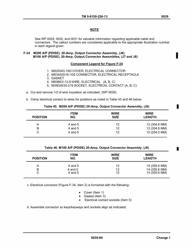
TM 9-6150-226-13 0039
0039-89 Change 1
See WP 0029, 0030, and 0031 for valuable information regarding applicable cable and connectors. The callout numbers are considered applicable to the appropriate illustration number in each legend given. F-34 M200 A/P (PDISE), 20-Amp, Output Connector Assembly, (J6) M100 A/P (PDISE), 20-Amp, Output Connector Assemblies, (J7 and J8)
Component Legend for Figure F-34
1. MS25043-16D COVER, ELECTRICAL CONNECTOR 2. MS3402D16-10S CONNECTOR, ELECTRICAL RECEPTACLE 3. GASKET 4. M5086/2-12-9 WlRE, ELECTRlCAL (A, B, C) 5. M39029/30-219 SOCKET, ELECTRlCAL CONTACT (A, B, C)
a. Cut and remove 1/2 of wire insulation as indicated. (WP 0029) b. Crimp electrical contact to wires for positions as noted in Table 45 and 46 below:
Table 45. M200 A/P (PDISE) 20-Amp, Output Connector Assembly, (J6) ITEM WIRE WIRE
POSITION NO. SIZE LENGTH
A 4 and 5 12 12 (304.8 MM) B 4 and 5 12 12 (304.8 MM) C 4 and 5 12 10 (254.0 MM)
Table 46. M100 A/P (PDISE) 20-Amp, Output Connector Assembly, (J8) ITEM WIRE WIRE
POSITION NO. SIZE LENGTH
A 4 and 5 12 14 (355.6 MM) B 4 and 5 12 14 (355.6 MM) C 4 and 5 12 14 (355.6 MM)
c. Electrical connector (Figure F-34, Item 2) is furnished with the following:
Cover (Item 1) Gasket (Item 3) Electrical contact sockets (Item 5)
d. Assemble connector so keys/keyways and sockets align as indicated.
NOTE

TM 9-6150-226-13 0039
Change 1 0039-90
Figure F-34. M200/100 A/P (PDISE) 20-Amp, Output Connector Assemblies.

TM 9-6150-226-13 0039
See WP 0029, 0030, and 0031 for valuable information regarding applicable cable and connectors. The callout numbers are considered applicable to the appropriate illustration number in each legend given. F-35 M100 A/P (PDISE) 20-Amp, Output Connector Assembly, (J7)
Component Legend for Figure F-35
1. MS25043-16D COVER, ELECTRICAL CONNECTOR 2. MS3402D16-10S CONNECTOR, ELECTRICAL RECEPTACLE 3. GASKET 4. M5086/2-12-9 WlRE, ELECTRlCAL (A, B, C) 5. M39029/30-219 SOCKET, ELECTRlCAL CONTACT (A, B, C)
a. Cut and remove wire insulation as indicated. (WP 0029) b. Crimp electrical contact to wires for positions as noted in Table 47 below:
Table 47. M100 A/P (PDISE) 20-Amp, Output Connector Assembly, (J7) ITEM WIRE WIRE
POSITION NO. SIZE LENGTH
A 4 and 5 12 25 (635.0 MM) B 4 and 5 12 15 (381.0 MM) C 4 and 5 12 15 (381.0 MM)
c. Electrical connector (Figure F-35, Item 2) is furnished with the following:
Cover (Item 1) Gasket (Item 3) Electrical contact sockets (Item 5)
d. Assemble connector so keys/keyways and sockets align as indicated.
NOTE
0039-91 Change 1

TM 9-6150-226-13 0039
Change 1 0039-92
Figure F-35. M100 A/P (PDISE) 20-Amp, Output Connector Assembly, (J7) END OF WORK PACKAGE

TM 9-6150-226-13 0040
SUPPORTING INFORMATION DISE/PDISE EQUIPMENT
TORQUE LIMITS
GENERAL This section provides general torque limits for screws used on the DISE and PDISE systems. Special torque limits are indicated in the maintenance procedures for applicable components. The general torque limits given in this appendix shall be used when specific torque limits are not indicated in the maintenance procedure. These general torque limits cannot be applied to screws that retain rubber components. The rubber components will be damaged before the correct torque limit is reached. If a special torque limit is not given in the maintenance instructions, tighten the screw or nut until it touches the metal bracket; then tighten it one more turn. TORQUE LIMITS. Table 1 lists torque limits for circuit breaker lugs. Table 2 lists dry torque limits. Dry torque limits are used on screws that do not have lubricants applied to the threads. This is how to determine breakaway torque: Thread nut onto screw or bolt until at least two threads stick out. Nut shall not make contact with a mating part. Stop the nut. Torque necessary to begin turning nut again is the breakaway torque. Table 3 shows these limits for breakaway nut torque limits.
Table 1. (DISE only) Torque Limits for Circuit Breaker Lugs.
On the M200 feeder center only, torque the main circuit breaker (200 Amp) input lugs to 180 lb-in (20.3 N.m). Torque all other circuit breaker lugs according to wire size connected as follows:
Torque Wire Size in.-lb N.m
AWG +5 in.-lb ±0.6 N.m 18-20 25 10-14 30
8 30 6 35 4 35 3 35 2 40 1 45
1/0 50 2/0 50 4/0 50
2.8 3.4 3.4 4 4 4
4.5 5.1 5.7 5.7 5.7
NOTE
0040-1

TM 9-6150-226-13 0040
If you have PDISE equipment, torque all circuit breaker lugs according to wire size as follows:
Table 2. (PDISE) Torque Limits for Circuit Breaker Lugs.
Wire Size Torque AWG in.-lb N.m. 18 20-23 2.3-2.6 14-10 33-35 3.7-4 8 38-40 4.3-4.5 6-4 42-45 4.7-5 3-1/0 45-50 5-5.7 4/0 275 31
Do not reuse self-locking nuts that do not meet minimum breakaway torque.
Table 3. Torque Limits for Self-Locking Nuts. Minimum Breakaway Minimum Breakaway Thread Size Torque in.-lb (N.m) Thread Size Torque in.-lb (N.m) 10-32 2.0 (0.23) 5/8-18 32.0 (3.62) 1/4-28 3.5 (0.40) 3/4-16 50.0 (5.65) 5/16-24 6.5 (0.73) 7/8-14 70.0 (7.91) 3/8-24 9.5 (1.07) 1-12 90.0 (10.17) 7/16-20 14.0 (1.58) 1-1/8-12 117.0 (13.22) 1/2-20 18.0 (2.03) 1-1/4-12 143.0 (16.16) 9/16-18 24.0 (2.71)
END OF WORK PACKAGE
0040-2
NOTE
NOTE

Chapter 8
REAR MATTER


RECOMMENDED CHANGES TO PUBLICATIONS AND BLANK FORMS
For use of this form, see AR 25-30; the proponent agency is OAASA
Use Part II (reverse) for Repair Parts and Special Tool Lists (RPSTL) and Supply Catalogs/Supply Manuals (SC/SM).
DATE 30 August 2002
TO: (Forward to proponent of publication or form) (Include ZIP Code) Commander, US Army CECOM LCMC ATTN: AMSEL-LC-LEO-E-ED Fort Monmouth, NJ 07703-5006
FROM: (Activity and location) (Include ZIP Code) Jane Q. Doe, SFC 1234 Any Street Anytown, AL 34565
PART I - ALL PUBLICATIONS (EXCEPT RPSTL AND SC/SM) AND BLANK FORMS PUBLICATION/FORM NUMBER TM 11-1234-567-14
DATE 16 Sep 2001
TITLE Operator, Field and Sustainment Support Maintenance Manual for Radio, AN/ABC-123
ITEM PAGE PARA- GRAPH LINE FIGURE
NO. TABLE RECOMMENDED CHANGES AND REASON 1 WP0005
PG 3 2 Test or Correctiive Action column should identify a different WP number.
TYPED NAME, GRADE OR TITLE Jane Q. Doe, SFC
TELEPHONE EXCHANGE/AUTOVON, PLUS EXTENSION 123-4567
SIGNATURE
DA FORM 2028, FEB 74 REPLACES DA FORM 2028, 1 DEC 68, WHICH WILL BE USED. APD V4.00
TO: (Forward to proponent of publication or form) (Include ZIP Code)
FROM: (Activity and location) (Include ZIP Code)
DATE
PART II- REPAIR PARTS AND SPECIAL TOOL LISTS AND SUPPLY CATALOGS/SUPPLY MANUALS PUBLICATION/FORM NUMBER
DATE
TITLE
PAGE NO.
COLM NO.
LINE NO.
NATIONAL STOCK
NUMBER
REFERENCE
NO.
FIGURE
NO.
ITEM NO.
TOTAL NO. OF MAJOR
ITEMS SUPPORTED
RECOMMENDED ACTION
PART III - REMARKS (Any general remarks or recommendations, or suggestions for improvement of publications and blank forms. Additional blank sheets may be used if more space is needed.)
TYPED NAME, GRADE OR TITLE
TELEPHONE EXCHANGE/AUTOVON, PLUS EXTENSION
SIGNATURE
APD V4.00

RECOMMENDED CHANGES TO PUBLICATIONS AND
BLANK FORMS For use of this form, see AR 25-30; the proponent agency is OAASA
Use Part II (reverse) for Repair Parts and Special Tool Lists (RPSTL) and Supply Catalogs/Supply Manuals (SC/SM).
DATE
TO: (Forward to proponent of publication or form) (Include ZIP Code)
FROM: (Activity and location) (Include ZIP Code)
PART I - ALL PUBLICATIONS (EXCEPT RPSTL AND SC/SM) AND BLANK FORMS PUBLICATION/FORM NUMBER
DATE
TITLE
ITEM PAGE PARA- GRAPH LINE FIGURE
NO. TABLE RECOMMENDED CHANGES AND REASON
TYPED NAME, GRADE OR TITLE
TELEPHONE EXCHANGE/AUTOVON, PLUS EXTENSION
SIGNATURE
DA FORM 2028, FEB 74 REPLACES DA FORM 2028, 1 DEC 68, WHICH WILL BE USED. APD V4.00

TO: (Forward to proponent of publication or form) (Include ZIP Code)
FROM: (Activity and location) (Include ZIP Code)
DATE
PART II- REPAIR PARTS AND SPECIAL TOOL LISTS AND SUPPLY CATALOGS/SUPPLY MANUALS PUBLICATION/FORM NUMBER
DATE
TITLE
PAGE NO.
COLM NO.
LINE NO.
NATIONAL STOCK
NUMBER
REFERENCE
NO.
FIGURE
NO.
ITEM NO.
TOTAL NO. OF MAJOR
ITEMS SUPPORTED
RECOMMENDED ACTION
PART III - REMARKS (Any general remarks or recommendations, or suggestions for improvement of publications and blank forms. Additional blank sheets may be used if more space is needed.)
TYPED NAME, GRADE OR TITLE
TELEPHONE EXCHANGE/AUTOVON, PLUS EXTENSION
SIGNATURE
APD V4.00
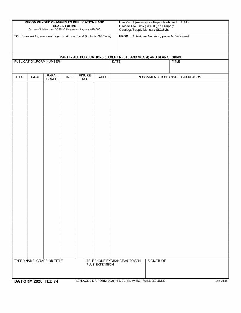
RECOMMENDED CHANGES TO PUBLICATIONS AND
BLANK FORMS For use of this form, see AR 25-30; the proponent agency is OAASA
Use Part II (reverse) for Repair Parts and Special Tool Lists (RPSTL) and Supply Catalogs/Supply Manuals (SC/SM).
DATE
TO: (Forward to proponent of publication or form) (Include ZIP Code)
FROM: (Activity and location) (Include ZIP Code)
PART I - ALL PUBLICATIONS (EXCEPT RPSTL AND SC/SM) AND BLANK FORMS PUBLICATION/FORM NUMBER
DATE
TITLE
ITEM PAGE PARA- GRAPH LINE FIGURE
NO. TABLE RECOMMENDED CHANGES AND REASON
TYPED NAME, GRADE OR TITLE
TELEPHONE EXCHANGE/AUTOVON, PLUS EXTENSION
SIGNATURE
DA FORM 2028, FEB 74 REPLACES DA FORM 2028, 1 DEC 68, WHICH WILL BE USED. APD V4.00

TO: (Forward to proponent of publication or form) (Include ZIP Code)
FROM: (Activity and location) (Include ZIP Code)
DATE
PART II- REPAIR PARTS AND SPECIAL TOOL LISTS AND SUPPLY CATALOGS/SUPPLY MANUALS PUBLICATION/FORM NUMBER
DATE
TITLE
PAGE NO.
COLM NO.
LINE NO.
NATIONAL STOCK
NUMBER
REFERENCE
NO.
FIGURE
NO.
ITEM NO.
TOTAL NO. OF MAJOR
ITEMS SUPPORTED
RECOMMENDED ACTION
PART III - REMARKS (Any general remarks or recommendations, or suggestions for improvement of publications and blank forms. Additional blank sheets may be used if more space is needed.)
TYPED NAME, GRADE OR TITLE
TELEPHONE EXCHANGE/AUTOVON, PLUS EXTENSION
SIGNATURE
APD V4.00
By Order of the Secretary of the Air Force:
By Order of the Secretary of the Army:
GEORGE W. CASEY, JR General, United States Army
Chief of Staff
0829412
JOYCE E. MORROW Administrative Assistant to the
Secretary of the Army
Official:
T. MICHAEL MOSELEYGeneral, USAFChief of StaffOfficial:
BRUCE CARLSONGeneral, USAFCommand, AFMC
Army Distribution: To be distributed in accordance with the initial distribution number (IDN) 0255782 requirements for TM 9-6150-226-13.


PIN: 069909-000

This fine document...
Was brought to you by me:
Liberated Manuals -- free army and government manuals
Why do I do it? I am tired of sleazy CD-ROM sellers, who take publicly available information, slap “watermarks” and other junk on it, and sell it. Those masters of search engine manipulation make sure that their sites that sell free information, come up first in search engines. They did not create it... They did not even scan it... Why should they get your money? Why are not letting you give those free manuals to your friends?
I am setting this document FREE. This document was made by the US Government and is NOT protected by Copyright. Feel free to share, republish, sell and so on.
I am not asking you for donations, fees or handouts. If you can, please provide a link to liberatedmanuals.com, so that free manuals come up first in search engines:
<A HREF=http://www.liberatedmanuals.com/>Free Military and Government Manuals</A>
– SincerelyIgor Chudovhttp://igor.chudov.com/
– Chicago Machinery Movers