Embed Size (px)
Citation preview
6. Peel away the White adhesive liner and firmly press the exposed tape surface to the mounting bracket (fig. 6).7. Remove the Red adhesive liner and carefully position the bracket in the desired location (fig. 7). Press bracket firmly into place.Important: Ensure that the front of the brack-et is mounted facing the driver (Fig 8.). The foam tape contains a strong adhesive that is not easily repositioned once installed. Take care to position the bracket correctly when installing using this method of attachment.NOTE: For maximum effectiveness, warm the adhe-sive surface with a hair dryer.8. To ensure a proper bond, the adhesive requires time to cure. For best adhesion, do not insert the brake control unit into the bracket or allow the bracket to support weight for 72 hours.9. Once the adhesive has cured, align the slots along the sides of the Odyssey II™ with the ridges in the slide-in bracket. Slide the brake control into the bracket from the front until it snaps securely into place (fig. 10).
Permanent Mounting:10. Place the mounting bracket into the desired position on the vehicle and mark the location of the bracket mounting slots.11. Using a 1⁄8” drill bit, drill the holes marked in step 2 into the mounting surface.Caution: Ensure that the area directly behind the mounting surface is clear of obstructions that may be damaged while drilling.12. Using a screwdriver or 1⁄4” nut driver, secure the bracket to the vehicle with the two 1⁄4” self tap-ping screws (provided). Take care 20o
Fron
t of V
ehicl
e
fig. 2
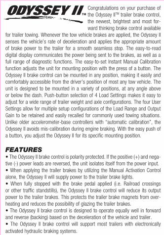
CONTROLS / COMPONENTS1. LED Display2. Output Gain Increase Button3. Output Gain Decrease Button4. Manual Activation Pressure Button 5. Load Range / Calibration Button6. User Setting Selection Button7. User Setting Selection Indicator8. Relative Output Display9. Harness Connector10. Wiring Harness Adapter
MOUNTINGNote: Read all instructions thoroughly before beginning.The Odyssey II™ brake control can be mounted in an unlimited number of positions, making it easily and comfortably accessible from the driver’s position of most any tow vehicle. The Odyssey II has an unlimited vertical plane operating range (fig. 1) and a 20o range horizontally (fig. 2 & 3). The unit is designed to be mounted at any angle above or below the dash of the tow vehicle (fig. 4 & 5), with no degradation of performance.
Congratulations on your purchase of the Odyssey IITM trailer brake control, the newest, brightest and most for-ward thinking brake control available
for trailer towing. Whenever the tow vehicle brakes are applied, the Odyssey II senses the vehicle’s rate of deceleration and applies the appropriate amount of brake power to the trailer for a smooth seamless stop. The easy-to-read digital display communicates the power being sent to the brakes, as well as a full range of diagnostic functions. The easy-to-set Instant Manual Calibration function adjusts the unit for mounting position with the press of a button. The Odyssey II brake control can be mounted in any position, making it easily and comfortably accessible from the driver’s position of most any tow vehicle. The unit is designed to be mounted in a variety of positions, at any angle above or below the dash. Push-button selection of 4 Load Settings makes it easy to adjust for a wide range of trailer weight and axle configurations. The four User Settings allow for multiple setup configurations of the Load Range and Output Gain to be retained and easily recalled for commonly used towing situations. Unlike older accelerometer-base controllers with “automatic calibration”, the Odyssey II avoids mis-calibration during engine braking. With the easy push of a button, you adjust the Odyssey II for its specific mounting position.
FEATURES• The Odyssey II brake control is polarity protected. If the positive (+) and nega-tive (-) power leads are reversed, the unit isolates itself from the power input.• When applying the trailer brakes by utilizing the Manual Activation Control alone, the Odyssey II will supply power to the trailer brake lights.• When fully stopped with the brake pedal applied (i.e. Railroad crossings or other traffic standstills), the Odyssey II brake control will reduce its output power to the trailer brakes. This protects the trailer brake magnets from over-heating and reduces the possibility of glazing the trailer brakes.• The Odyssey II brake control is designed to operate equally well in forward and reverse (backing) based on the deceleration of the vehicle and trailer.• The Odyssey II brake control will support most trailers with electronically activated hydraulic braking systems.
Above Dash Mounting (Without Bracket)
fig. 4
20ofig. 3
Verti
cal (
Up)
Factory Pigtail Brake Control Wire Color Wire Color Function
Red Connect To Black 12 Volt Positive (+)Light Blue Connect To Red Stop LightBlack Connect To White Ground (-)Dark Blue Connect To Blue Trailer BrakesBrown Not Used
White with Red Stripe Connect To Black 12 Volt Positive (+)Blue with White Stripe Connect To Red Stop LightGreen with Black Stripe Connect To White Ground (-)Blue Connect To Blue Trailer Brakes
Red with Black Stripe Connect To Black 12 Volt Positive (+)White with Tan Stripe Connect To Red Stop LightBlack Connect To White Ground (-)Blue Connect To Blue Trailer Brakes
Red Connect To Black 12 Volt Positive (+)Light Green Connect To Red Stop LightWhite Connect To White Ground (-)Dark Blue Connect To Blue Trailer BrakesBrown Not Used
Pink Connect To Black 12 Volt Positive (+)Red Connect To Red Stop LightWhite Connect To White Ground (-)Blue Connect To Blue Trailer BrakesBrown Not Used
Blue Connect To Black 12 Volt Positive (+)White with Black Stripe Connect To Red Stop LightBlack Connect To White Ground (-)Brown with White Stripe Connect To Blue Trailer Brakes
Red Connect To Black 12 Volt Positive (+)Red with Green Stripe Connect To Red Stop LightBlack Connect To White Ground (-)Brown with White Stripe Connect To Blue Trailer BrakesRed with Light Blue Stripe Not Used
Black with Green Stripe Connect To Black 12 Volt Positive (+) Green with White Stripe Connect To Red Stop LightBrown Connect To White Ground (-)Red Connect To Blue Trailer BrakesGreen Not Used
ORIGINAL EQUIPMENT FACTORY BRAKE CONTROL CONNECTOR PIGTAILSelect the connector that matches your factory supplied brake control connector pigtail
CHEVROLET
DODGE
FORD
FORD (Optional)
TOYOTA
360o
fig. 1Front of Vehicle
NISSAN
fig. 7
ONSET OF BRAKING EVENT
BRAK
E CO
NTRO
L OU
TPUT
POW
ER (%
)
L1
L4
L3
L2
DECELERATION
MAXIMUM OUTPUT POWER TO TRAILER BRAKES
(USER DEFINED)
LOAD RANGE OUTPUT GUIDELINESLOAD RANGE SETTING GUIDELINES
Trailer GVW is LESS Than Tow Vehicle GVW
CAUTION: Do Not Exceed Gross Combined Weight Rating (GCWR)
Trailer GVW is APPROXIMATELY EQUAL TO Tow Vehicle GVW
Trailer GVW is UP TO 50% MORE Than Tow Vehicle GVW
Trailer GVW is OVER 100% MORE Than Tow Vehicle GVW
Trailer GVW is UP TO 75% MORE Than Tow Vehicle GVW
L I L 2L 2L 2 L 3
L 3 L 4L 4
+-
BATT (BLACK)GND (WHITE)
12 V
OLT
TOW
VEH
ICLE
BAT
TERY
BRAKECONTROL
WARNING: READ AND OBEYALL WARNINGS AND CAUTIONSPRINTED ON TOW VEHICLE BATTERY
BRAKES (BLUE)STLT (RED)
ONLY CONNECT BULB TO NEGATIVE (-) TERMINAL AS NEEDED
STANDARD 12V #1156AUTOMOTIVE BULB(USE SOCKET OR SOLDERWIRES TO BULB)
DO NOT CONNECT RED WIRETO POSITIVE (+) TERMINALUNTIL STEP 3
32810-998 Rev A 01/28/08© 2004-2008 Thule Towing Systems, Llc.
HONDA
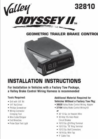
Tools Required:• Drill with 1/8” Bit• 1/4” Nut Driver• Phillips Screwdriver• Wiring Connector Crimping Tool• Wire Cutter/Stripper• End Wrenches• Probe Style Test Light
Additional Material Required for Vehicles Without a Factory Tow Pkg: • 30520 Valley Brake Control Wiring Adapter • 37194 Valley Brake Control Wiring Kit or • 30’ 12 Ga. (or Heavier) Wire • 30 Amp 12v Auto-Reset Circuit Breaker • 10/12 Ga. #10 Ring Terminal • 10/12 Ga.
3⁄8” Ring Terminal
• 10/12 Ga. Butt Connectors • 14/16 Ga. Wire Tap • 4” Cable Ties
32810
INSTALLATION INSTRUCTIONS For Installation in Vehicles with a Factory Tow Package, a Valley Brake Control Wiring Harness is recommended
®
1.
4.
2.
3.
5. 6.
7.8.
9.
10.
1. Determine an appropriate mounting location that is easily accessible from a comfortable seated driving position.Note: The brake control unit must be securely mounted to a solid surface (i.e. onto or beneath the vehicles dash) within easy reach of the driver.Important: Ensure all buttons and controls are easily accessible from the driver’s position. Do not mount the unit in such a manner that would prohibit accessibility to the control features of the brake control.Caution: Avoid mounting the Odyssey II brake control near an RF source (i.e. CB or 2-way radio).2. The slide-in bracket can be permanently mounted to the vehicle with the screws provided. For a temporary installation, use the double-sided foam tape included with the brake control.
Temporary Mounting:3. Clean the mounting surface of the mounting bracket and the desired mounting area using the surface prep cleaning kit (provided). Wipe in a straight line in one direction only.Note: If the temperature in the vehicle is below 70o F, run the vehicle’s heater until the mounting surface and bracket are warm.4. Dry both surfaces with a clean cloth and repeat step 3.5. Wipe both surfaces with the alcohol swab and allow to dry.
Below Dash Mounting (with Bracket)
fig. 5
fig. 6
Mount Facing Driver’s Seat
fig. 8
not to strip the holes by over-tightening the screws (fig. 10).13. Align the slots along the sides of the Odyssey II with the ridges in the slide-in bracket. Slide the brake control into the bracket from the front until it snaps securely into place (fig. 9).
WIRINGNote: Read all instructions thoroughly before beginning.The use of proper gauge wire is critical when installing the Odyssey II™ brake control. Lesser gauge wire may result in less than desirable braking operation. Black and Blue wire gauges are as follows:• 1 - 2 Axle Trailers: 12 Gauge Wire Minimum• 3 - 4 Axle Trailers: 10 Gauge Wire Minimum
Caution: Improper connection of a trailer break-away kit may cause damage to the trailer brake system and/or the brake control.
FOR TOW VEHICLES EQUIPPED WITH ORIGINAL EQUIPMENT FACTORY TRAILER TOW PACKAGES:As vehicle wiring differs by manufacturer, use of a pre-wired brake control harness is recommended. Valley offers a wide range of modular harnesses designed to mate directly between the tow vehicle’s factory brake control plug and the Odyssey II™’s connector.Note: As wire colors differ by manufacturer, the vehicle harness wire colors
may differ from those on the brake control pigtail. If a factory supplied harness must be used, refer to the following chart, the tow vehicle’s owners manual and the instructions supplied with the original equipment factory connector for correct brake control wiring.Caution: Ensure the tow vehicles brake control power circuit (+) is capable of delivering the required amount of current needed
fig. 10
for the trailers braking system (Refer to the tow vehicle and trailer owners manuals). If the brake control power circuit (+) does not meet the demand, wire directly to the battery (steps 1 - 15 follow-ing).
FOR TOW VEHICLES NOT EQUIPPED WITH ORIGINAL EQUIPMENT FACTORY TRAILER TOW PACKAGES:The brake control must be spliced into the vehicle’s existing wiring harness. Use Valley harness 30520 to connect the Odyssey II™ in the following manner:1. Read all instructions thoroughly before beginning.2. Soldered connections are favorable when wiring the Odyssey II brake control, however crimp-style connectors are acceptable in making these connections.3. Mount a 30 amp automotive style circuit breaker near the tow vehicle’s positive (+) battery terminal. Using a length of 10 ga. stranded wire, strip 5⁄16” of insulation from one end and attach a 3⁄8” 12 ga. crimp-style ring terminal. Strip 5⁄16” from the opposite end and attach a #10 12 ga. Crimp-style ring terminal. Connect this lead to the circuit breaker terminal labeled “BATT”. The opposite end will mount to the vehicle’s positive (+) battery terminal during step 14.Caution: Do not attach to the vehicle’s positive (+) battery terminal at this time.4. Feed a length of 10 ga. stranded duplex wire (white & black) from the brake control to the vehicles battery compartment.Caution: When passing wire through sheet metal, always utilize an existing grommet, add a grommet or use silicone rubber to insulate the wire from the hole.5. Attach a 3⁄8” 12 ga. ring terminal to the White wire, and a #10 12 ga. ring terminal to the Black wire in the same manner as step 2.6. Attach the Black wire to the circuit breaker terminal labeled “AUX”.7. Attach the White wire to the vehicles Negative (-) battery post.
DODGE (Optional)
8. From the driver’s area, attach the wiring harness’s Black wire to the opposite end of the Black wire attached to the “AUX” side of the circuit breaker using a yellow 10/12 ga. butt connector or by soldering the leads together.9. Attach wiring harness’s White wire to the opposite end of the White wire leading to the vehicles negative (-) battery terminal using a yellow 10/12 ga. butt connector or by soldering the leads together.10A. For 1989-1991 Ford E & F-Series Trucks & Vans with anti-lock brakes: (All other vehicles continue to Step 9B)Locate the crescent shaped turn signal harness connector (fig. 11) located on the steering column under the dash.The connector will have two rows of wires. A row of four wires and a row of seven wires. Attach wiring harness’s Red wire to the Light Green wire (second in the row of seven) with a 14 ga. wire tap.Caution: Do not connect to the Red wire with the Green Stripe as serious damage may occur.10B. For All Other Vehicles:Locate the stop light switch on the back side of the vehicles brake pedal. Determine which side of the switch is the “cold” or switched side by probing the terminals of the switch with a test light or current meter. The cold ter-minal will only indicate power when the brake pedal is depressed. Connect the wiring harness’s Red wire to the cold side of the stop light switch with a 14 ga. wire tap.11. Feed a length of 10 ga. Blue stranded wire from the brake control mounting area to the trailer connector at the rear of the vehicle.Caution: When passing wire through sheet metal, always utilize an existing grommet, add a grommet or use silicone rubber to insulate the wire from the hole.12. Attach the wiring harness’s Blue wire to the Blue 10 Ga. wire using a 10/12 ga. butt connector.
+-
LIGHT GREEN WIRE
fig. 11
13. At the rear of the vehicle, attach the Blue wire to the vehicle’s trailer connector brake terminal (see the connector wiring diagram for the correct terminal location).Note: Ensure the trailer connector ground (-) terminal is wired in a manner sufficient to support the trailer’s amperage draw.Refer to the connector manufacturer’s installation instructions for additional details.14. Connect the wire from the “BATT” side of the circuit breaker to the vehicle’s positive (+) battery terminal.Note: The Black “Battery” wire must be connected directly to the tow vehicle’s positive (+) battery terminal via a self-resetting 30 amp circuit breaker. Do not attempt to connect this wire to the vehicle’s fuse panel or other accessory wiring. Failure to connect directly to the vehicle battery may damage vehicle wiring and cause trailer brake failure.15. Plug the brake control harness into the brake control’s wiring harness adapter.
+-
BATT (BLACK)
STLT (RED)BRAKES (BLUE)
12 V
OLT
TOW
VEH
ICLE
BAT
TERY
BATT
AUXWIRE TAP
BRAKE PEDAL SWITCHCONNECT TO COLD (SWITCHED) SIDE
(ONLY ON WHEN PEDAL IS DEPRESSED)
30 AMP 12vAUTO-RESET
CIRCUIT BREAKER
CAUTION: DISCONNECT TOW VEHICLES NEGATIVE (-) BATTERY CABLE PRIOR TO WIRING BRAKE CONTROL
TRAILER CONNECTOR
BRAKECONTROL
10 GA.WIRE
WARNING: READ AND OBEYALL WARNINGS AND CAUTIONSPRINTED ON TOW VEHICLE BATTERY
10 GA.WIRE
LIGHT GREEN WIRE
SPLICE THE RED STOP LIGHT WIRE FROM THE BRAKE CONTROL TO THE LIGHT GREEN WIRE ON THE TURN SIGNAL HARNESS (ILLUSTRATED ABOVE) USING A WIRE TAP (PROVIDED).
NOTE: FOR 1989 - 1991 FORD F & E-SERIES TRUCKS AND VANS WITH ANTI-LOCK BRAKES:DO NOT CONNECT TO BRAKE PEDAL SWITCH.
TURN SIGNAL HARNESS CONNECTORLOCATED UNDER THE VEHICLE DASHNEAR THE STEERING COLUMN
GND (WHITE)
MANUAL CALIBRATIONWhen you first install the Odyssey IITM brake control and apply the brakes for the first time, the display on the unit will flash “CL”, indicating that the brake control needs to be calibrated to its current mounting position. To calibrate with the tow vehicle approximately level and brakes NOT applied, simply press and hold the Load Range Selector / Calibration Button for a few seconds until a steady “CL” appears.
If the unit’s mounting angle has changed or if “CL” flashes at any point, then re-calibration is required. Without pressing the brake pedal, press and HOLD the Load Range / Calibration Button until the “CL” appears, while on a level surface. Recalibration of the Odyssey II brake control will not affect the selected Load Range or User Settings. Once calibrated, using the procedure above, the Load Range setting may be viewed by tapping the Load Range button.
Note: To prevent accidental or false calibration, the calibration mode is locked out and unavailable when the brakes are engaged.
MANUAL TRAILER BRAKE APPLICATIONThe Manual Trailer Brake Application Pressure Button is designed to apply trailer brakes (when needed) independently of the tow vehicle braking system. Pressing on the button will apply a proportionate amount of trailer brakes to the amount of pressure being applied to the button. Output is represented by an LED bar graph on the main display of the unit.Note: Caution should always be exercised when applying trailer brakes independently of the vehicle braking system to avoid fishtailing or skid-ding.
SETUPOnce the wiring is complete, the brake control’s LED display will indicate one the following, illustrating the brake controls activity:
• Power Conservation Mode - No Motion or Activity for 55 min-utes or Longer. The Odyssey II will come instantly to full power mode as the brake pedal is depressed.
• No Trailer Connected – Odyssey II is Receiving Power and is Active.
• Trailer is Connected – Odyssey II is Receiving Power and is Active.
• Manual Lever Applied - No Trailer Connected (Applies to Manual Activation Pressure Switch only).
• Manual Activation Pressure Button or Vehicle Brakes Applied - Trailer is Connected (Output reading is based on Output Gain setting and position of Manual Activation Pressure Switch, if applied).
LOAD RANGE SETTINGThe Load Range should be set prior to adjusting the Output Power setting. This function has been designed to provide for a more aggressive output setting to the trailer brakes based upon the total trailer weight (see chart at right). Load Range is available in four levels - L1, L2, L3 and L4. Simply pressing the Load Range Selector will cycle between the levels in a rota-tion (see Controls/Components on page 3 for Load Range Selector Button identification).
C L(Flashing)
(Blank)
0CTO 0 I 99
Each incremental setting increases the sensitivity of the unit’s internal sen-sor, increasing the trailer brake contribution to the overall stopping power of the vehicle/trailer combination.
Level 1 Setting As brakes are applied, braking power initiates and increas-es with the deceleration of the vehicle.Level 2 Setting As brakes are applied, braking power initiates at approxi-mately 18% higher than level 1 and increases with the deceleration of the vehicle.Level 3 Setting As brakes are applied, braking power initiates at approxi-mately 21% higher than level 2 and increases with the deceleration of the vehicle.Level 4 Setting As brakes are applied, braking power initiates at approxi-mately 15% higher than level 3 and increases with the deceleration of the vehicle.Caution: Increasing the Load Range setting should NOT be utilized as an option to adjusting or repairing trailer brakes.Load Range settings should be based on the driver’s individual preferences and the overall condition of the trailer brakes. Refer to the charts above for recommended baseline load settings based on standard vehicle and trailer combinations.
OUTPUT SETTINGOnce the desired Load Range has been determined and set, the power output range must be adjusted for the individual trailer being towed.1. Connect the desired trailer to the tow vehicle.2. Start the tow vehicle to ensure sufficient battery power is being supplied
L I L 2 L 3 L 4
to the brake control. While parked, with foot OFF the brake pedal, press the Manual Activation Button to full output (indicated by the bar graph on the display) and press the Output Gain Buttons until the LED display indicates 5.0.3. Release the Manual Activation Button and drive the vehicle and trailer forward on a dry level surface at 25 mph. Ensure that ample distance is available for safe braking and firmly apply the brake control ManualActivation Button to full output.
If Trailer Brakes Lock Up:Reduce power to the trailer brakes by pressing the Output Gain Decrease Button to achieve a lower setting.
If Trailer Braking was Insufficient:Increase power to the trailer brakes by pressing the Output Gain Increase Button to achieve a higher setting.4. Continue to repeat step 3 until the desired power output has been achieved. The brake control output should be just below the point where
the trailer wheels lock up, yet there is sufficient force to allow for maximum brake force.5. Perform additional low speed stops (25 mph) utilizing the tow vehicles brake pedal to ensure smooth combination braking between the tow vehicle and the trailer.Caution: Increasing the power output setting should NOT be utilized as an option to adjusting or repairing trailer brakes.NOTE: In certain situations trailer brakes may not be capable of locking up. This situation can be associated with brake wear, overall trailer weight, trailer length and/or wire gauge. If the trailer brakes will not lock up during the setup procedures, it is recommended that all components of the braking system are checked to ensure safe towing.Caution: On some vehicles, manual operation of trailer brakes will not override the tow vehicle’s cruise control operation.
USER SELECTION SETTINGThe Odyssey II™ will retain four separate combinations of the Output Gain and Load Range settings. This feature is convenient when towing multiple trailers on a regular basis, consistent load variations, or when multiple users prefer different settings.1. Press the User Setting selection button until the desired setting number is reached (U1, U2, U3 or U4). Simply pressing the User Setting Button will cycle between the four user memory assignments in a rotation (see Controls/Components on page 3 for User Selector Button identification).
2. Using the methods described above, select the desired Load Range Settings and Output Gain settings as appropriate for the trailer and load combination. The unit will remember the gain and Load Range setting for the selected User ID.3. To record settings to another User number, press the User Selection Button until the desired ID is reached and repeat steps 1 and 2 above.
Note: The chosen User Setting is indicated by the Green LED’s on the right side of the unit’s display.
TROUBLESHOOTINGIn addition to indicating output power and Load Range settings, the Odyssey II is capable of communicating operating errors via its LED display.
• Trailer brake circuit may be lost or intermittent. Check the trailer connec-tor for a secure dry connection.Note: It is normal for the Odyssey II to flash OC for a few sec-onds after the circuit is disconnected.
U I U2 U3 U4
(Flashing)
0C
• Short Circuit Situation - The trailer brake circuit may be shorted to ground. Check for improper wiring. The unit will reset once the situation is corrected.
• Charging System Error - There may be a charging system problem or an inadequate connection to the tow vehicle’s bat-tery. The unit will reset once the situation is corrected.
BENCH TESTINGThe Odyssey II™ can be bench tested should correct operation be suspect. Remove the unit from the tow vehicle and wire to a 12 volt automotive bat-tery and #1156 automotive bulb as illustrated in figure 8.
Wiring1. Attach the unit’s Blue wire to one side of a standard #1156 12 volt automotive bulb by using a socket or by soldering the wire to the bulb.2. Attach a length of 16 ga. or larger wire to the other side of the #1156 bulb.3. Attach the White wire to the Negative (-) battery terminal.4. Attach the Black wire to the Positive (+) battery terminal.Note: Do not attach the unit’s Red wire or the bulb to the battery at this time.Caution: Do NOT touch the brake control’s RED wire to Ground (-) as this will destroy the unit.
Testing1. Repeatedly press the Output Gain Increase Button (+) until the display reads “9.9.”.2. Firmly press the Manual Activation Pressure Button. The unit’s LED display should flash “O.C”.3. Lay control flat on bench, then, press and hold Calibration Button until
SC
CS
“C.L” appears. 4. Connect the bulb to the Negative (-) battery terminal as illustrated in fig. 8.Slowly depress the Manual Activation Pressure Button. The LED display should increase from approximately “1.5.” to “9.9.”.5. Release the Manual Activation Pressure Button. The LED display should now display only decimal points. 6. Repeatedly Press the Load Range Selector. The LED display should read “L.1.” through “L.4.”. Adjust the load setting to “L.4.”.7. With the unit positioned horizontally, attach the Red wire to the Positive (+) battery terminal. The unit’s LED display will indicate an output reading. The reading may fluctuate for approximately 5 seconds.8. Tilt the front of the unit up to an approximately 45o angle. The LED display should increase to “9.9.” and the bulb should glow brightly.9. Retaining the unit at a 45o angle, repeatedly press (or, alternatively, press and hold) the Output Gain Decrease Button (-). The LED display should smoothly decrease from “9.9.” to approximately “0.5.”. 10. If the Odyssey II brake control does not function as described in the steps above, return the unit to an authorized distributor for service or replacement.
SERVICE & SUPPORT
• For questions regarding installation and usage, visit Valley on the web at www.valley.us.com or call (800) 423-6726 Monday through Friday, 9:00 AM to 6:00 PM Eastern Time.
GEOMETRIC TRAILER BRAKE CONTROL
fig. 9
6. Peel away the White adhesive liner and firmly press the exposed tape surface to the mounting bracket (fig. 6).7. Remove the Red adhesive liner and carefully position the bracket in the desired location (fig. 7). Press bracket firmly into place.Important: Ensure that the front of the brack-et is mounted facing the driver (Fig 8.). The foam tape contains a strong adhesive that is not easily repositioned once installed. Take care to position the bracket correctly when installing using this method of attachment.NOTE: For maximum effectiveness, warm the adhe-sive surface with a hair dryer.8. To ensure a proper bond, the adhesive requires time to cure. For best adhesion, do not insert the brake control unit into the bracket or allow the bracket to support weight for 72 hours.9. Once the adhesive has cured, align the slots along the sides of the Odyssey II™ with the ridges in the slide-in bracket. Slide the brake control into the bracket from the front until it snaps securely into place (fig. 10).
Permanent Mounting:10. Place the mounting bracket into the desired position on the vehicle and mark the location of the bracket mounting slots.11. Using a 1⁄8” drill bit, drill the holes marked in step 2 into the mounting surface.Caution: Ensure that the area directly behind the mounting surface is clear of obstructions that may be damaged while drilling.12. Using a screwdriver or 1⁄4” nut driver, secure the bracket to the vehicle with the two 1⁄4” self tap-ping screws (provided). Take care 20o
Fron
t of V
ehicl
e
fig. 2
CONTROLS / COMPONENTS1. LED Display2. Output Gain Increase Button3. Output Gain Decrease Button4. Manual Activation Pressure Button 5. Load Range / Calibration Button6. User Setting Selection Button7. User Setting Selection Indicator8. Relative Output Display9. Harness Connector10. Wiring Harness Adapter
MOUNTINGNote: Read all instructions thoroughly before beginning.The Odyssey II™ brake control can be mounted in an unlimited number of positions, making it easily and comfortably accessible from the driver’s position of most any tow vehicle. The Odyssey II has an unlimited vertical plane operating range (fig. 1) and a 20o range horizontally (fig. 2 & 3). The unit is designed to be mounted at any angle above or below the dash of the tow vehicle (fig. 4 & 5), with no degradation of performance.
Congratulations on your purchase of the Odyssey IITM trailer brake control, the newest, brightest and most for-ward thinking brake control available
for trailer towing. Whenever the tow vehicle brakes are applied, the Odyssey II senses the vehicle’s rate of deceleration and applies the appropriate amount of brake power to the trailer for a smooth seamless stop. The easy-to-read digital display communicates the power being sent to the brakes, as well as a full range of diagnostic functions. The easy-to-set Instant Manual Calibration function adjusts the unit for mounting position with the press of a button. The Odyssey II brake control can be mounted in any position, making it easily and comfortably accessible from the driver’s position of most any tow vehicle. The unit is designed to be mounted in a variety of positions, at any angle above or below the dash. Push-button selection of 4 Load Settings makes it easy to adjust for a wide range of trailer weight and axle configurations. The four User Settings allow for multiple setup configurations of the Load Range and Output Gain to be retained and easily recalled for commonly used towing situations. Unlike older accelerometer-base controllers with “automatic calibration”, the Odyssey II avoids mis-calibration during engine braking. With the easy push of a button, you adjust the Odyssey II for its specific mounting position.
FEATURES• The Odyssey II brake control is polarity protected. If the positive (+) and nega-tive (-) power leads are reversed, the unit isolates itself from the power input.• When applying the trailer brakes by utilizing the Manual Activation Control alone, the Odyssey II will supply power to the trailer brake lights.• When fully stopped with the brake pedal applied (i.e. Railroad crossings or other traffic standstills), the Odyssey II brake control will reduce its output power to the trailer brakes. This protects the trailer brake magnets from over-heating and reduces the possibility of glazing the trailer brakes.• The Odyssey II brake control is designed to operate equally well in forward and reverse (backing) based on the deceleration of the vehicle and trailer.• The Odyssey II brake control will support most trailers with electronically activated hydraulic braking systems.
Above Dash Mounting (Without Bracket)
fig. 4
20ofig. 3
Verti
cal (
Up)
Factory Pigtail Brake Control Wire Color Wire Color Function
Red Connect To Black 12 Volt Positive (+)Light Blue Connect To Red Stop LightBlack Connect To White Ground (-)Dark Blue Connect To Blue Trailer BrakesBrown Not Used
White with Red Stripe Connect To Black 12 Volt Positive (+)Blue with White Stripe Connect To Red Stop LightGreen with Black Stripe Connect To White Ground (-)Blue Connect To Blue Trailer Brakes
Red with Black Stripe Connect To Black 12 Volt Positive (+)White with Tan Stripe Connect To Red Stop LightBlack Connect To White Ground (-)Blue Connect To Blue Trailer Brakes
Red Connect To Black 12 Volt Positive (+)Light Green Connect To Red Stop LightWhite Connect To White Ground (-)Dark Blue Connect To Blue Trailer BrakesBrown Not Used
Pink Connect To Black 12 Volt Positive (+)Red Connect To Red Stop LightWhite Connect To White Ground (-)Blue Connect To Blue Trailer BrakesBrown Not Used
Blue Connect To Black 12 Volt Positive (+)White with Black Stripe Connect To Red Stop LightBlack Connect To White Ground (-)Brown with White Stripe Connect To Blue Trailer Brakes
Red Connect To Black 12 Volt Positive (+)Red with Green Stripe Connect To Red Stop LightBlack Connect To White Ground (-)Brown with White Stripe Connect To Blue Trailer BrakesRed with Light Blue Stripe Not Used
Black with Green Stripe Connect To Black 12 Volt Positive (+) Green with White Stripe Connect To Red Stop LightBrown Connect To White Ground (-)Red Connect To Blue Trailer BrakesGreen Not Used
ORIGINAL EQUIPMENT FACTORY BRAKE CONTROL CONNECTOR PIGTAILSelect the connector that matches your factory supplied brake control connector pigtail
CHEVROLET
DODGE
FORD
FORD (Optional)
TOYOTA
360o
fig. 1Front of Vehicle
NISSAN
fig. 7
ONSET OF BRAKING EVENT
BRAK
E CO
NTRO
L OU
TPUT
POW
ER (%
)
L1
L4
L3
L2
DECELERATION
MAXIMUM OUTPUT POWER TO TRAILER BRAKES
(USER DEFINED)
LOAD RANGE OUTPUT GUIDELINESLOAD RANGE SETTING GUIDELINES
Trailer GVW is LESS Than Tow Vehicle GVW
CAUTION: Do Not Exceed Gross Combined Weight Rating (GCWR)
Trailer GVW is APPROXIMATELY EQUAL TO Tow Vehicle GVW
Trailer GVW is UP TO 50% MORE Than Tow Vehicle GVW
Trailer GVW is OVER 100% MORE Than Tow Vehicle GVW
Trailer GVW is UP TO 75% MORE Than Tow Vehicle GVW
L I L 2L 2L 2 L 3
L 3 L 4L 4
+-
BATT (BLACK)GND (WHITE)
12 V
OLT
TOW
VEH
ICLE
BAT
TERY
BRAKECONTROL
WARNING: READ AND OBEYALL WARNINGS AND CAUTIONSPRINTED ON TOW VEHICLE BATTERY
BRAKES (BLUE)STLT (RED)
ONLY CONNECT BULB TO NEGATIVE (-) TERMINAL AS NEEDED
STANDARD 12V #1156AUTOMOTIVE BULB(USE SOCKET OR SOLDERWIRES TO BULB)
DO NOT CONNECT RED WIRETO POSITIVE (+) TERMINALUNTIL STEP 3
32810-998 Rev A 01/28/08© 2004-2008 Thule Towing Systems, Llc.
HONDA
Tools Required:• Drill with 1/8” Bit• 1/4” Nut Driver• Phillips Screwdriver• Wiring Connector Crimping Tool• Wire Cutter/Stripper• End Wrenches• Probe Style Test Light
Additional Material Required for Vehicles Without a Factory Tow Pkg: • 30520 Valley Brake Control Wiring Adapter • 37194 Valley Brake Control Wiring Kit or • 30’ 12 Ga. (or Heavier) Wire • 30 Amp 12v Auto-Reset Circuit Breaker • 10/12 Ga. #10 Ring Terminal • 10/12 Ga.
3⁄8” Ring Terminal
• 10/12 Ga. Butt Connectors • 14/16 Ga. Wire Tap • 4” Cable Ties
32810
INSTALLATION INSTRUCTIONS For Installation in Vehicles with a Factory Tow Package, a Valley Brake Control Wiring Harness is recommended
®
1.
4.
2.
3.
5. 6.
7.8.
9.
10.
1. Determine an appropriate mounting location that is easily accessible from a comfortable seated driving position.Note: The brake control unit must be securely mounted to a solid surface (i.e. onto or beneath the vehicles dash) within easy reach of the driver.Important: Ensure all buttons and controls are easily accessible from the driver’s position. Do not mount the unit in such a manner that would prohibit accessibility to the control features of the brake control.Caution: Avoid mounting the Odyssey II brake control near an RF source (i.e. CB or 2-way radio).2. The slide-in bracket can be permanently mounted to the vehicle with the screws provided. For a temporary installation, use the double-sided foam tape included with the brake control.
Temporary Mounting:3. Clean the mounting surface of the mounting bracket and the desired mounting area using the surface prep cleaning kit (provided). Wipe in a straight line in one direction only.Note: If the temperature in the vehicle is below 70o F, run the vehicle’s heater until the mounting surface and bracket are warm.4. Dry both surfaces with a clean cloth and repeat step 3.5. Wipe both surfaces with the alcohol swab and allow to dry.
Below Dash Mounting (with Bracket)
fig. 5
fig. 6
Mount Facing Driver’s Seat
fig. 8
not to strip the holes by over-tightening the screws (fig. 10).13. Align the slots along the sides of the Odyssey II with the ridges in the slide-in bracket. Slide the brake control into the bracket from the front until it snaps securely into place (fig. 9).
WIRINGNote: Read all instructions thoroughly before beginning.The use of proper gauge wire is critical when installing the Odyssey II™ brake control. Lesser gauge wire may result in less than desirable braking operation. Black and Blue wire gauges are as follows:• 1 - 2 Axle Trailers: 12 Gauge Wire Minimum• 3 - 4 Axle Trailers: 10 Gauge Wire Minimum
Caution: Improper connection of a trailer break-away kit may cause damage to the trailer brake system and/or the brake control.
FOR TOW VEHICLES EQUIPPED WITH ORIGINAL EQUIPMENT FACTORY TRAILER TOW PACKAGES:As vehicle wiring differs by manufacturer, use of a pre-wired brake control harness is recommended. Valley offers a wide range of modular harnesses designed to mate directly between the tow vehicle’s factory brake control plug and the Odyssey II™’s connector.Note: As wire colors differ by manufacturer, the vehicle harness wire colors
may differ from those on the brake control pigtail. If a factory supplied harness must be used, refer to the following chart, the tow vehicle’s owners manual and the instructions supplied with the original equipment factory connector for correct brake control wiring.Caution: Ensure the tow vehicles brake control power circuit (+) is capable of delivering the required amount of current needed
fig. 10
for the trailers braking system (Refer to the tow vehicle and trailer owners manuals). If the brake control power circuit (+) does not meet the demand, wire directly to the battery (steps 1 - 15 follow-ing).
FOR TOW VEHICLES NOT EQUIPPED WITH ORIGINAL EQUIPMENT FACTORY TRAILER TOW PACKAGES:The brake control must be spliced into the vehicle’s existing wiring harness. Use Valley harness 30520 to connect the Odyssey II™ in the following manner:1. Read all instructions thoroughly before beginning.2. Soldered connections are favorable when wiring the Odyssey II brake control, however crimp-style connectors are acceptable in making these connections.3. Mount a 30 amp automotive style circuit breaker near the tow vehicle’s positive (+) battery terminal. Using a length of 10 ga. stranded wire, strip 5⁄16” of insulation from one end and attach a 3⁄8” 12 ga. crimp-style ring terminal. Strip 5⁄16” from the opposite end and attach a #10 12 ga. Crimp-style ring terminal. Connect this lead to the circuit breaker terminal labeled “BATT”. The opposite end will mount to the vehicle’s positive (+) battery terminal during step 14.Caution: Do not attach to the vehicle’s positive (+) battery terminal at this time.4. Feed a length of 10 ga. stranded duplex wire (white & black) from the brake control to the vehicles battery compartment.Caution: When passing wire through sheet metal, always utilize an existing grommet, add a grommet or use silicone rubber to insulate the wire from the hole.5. Attach a 3⁄8” 12 ga. ring terminal to the White wire, and a #10 12 ga. ring terminal to the Black wire in the same manner as step 2.6. Attach the Black wire to the circuit breaker terminal labeled “AUX”.7. Attach the White wire to the vehicles Negative (-) battery post.
DODGE (Optional)
8. From the driver’s area, attach the wiring harness’s Black wire to the opposite end of the Black wire attached to the “AUX” side of the circuit breaker using a yellow 10/12 ga. butt connector or by soldering the leads together.9. Attach wiring harness’s White wire to the opposite end of the White wire leading to the vehicles negative (-) battery terminal using a yellow 10/12 ga. butt connector or by soldering the leads together.10A. For 1989-1991 Ford E & F-Series Trucks & Vans with anti-lock brakes: (All other vehicles continue to Step 9B)Locate the crescent shaped turn signal harness connector (fig. 11) located on the steering column under the dash.The connector will have two rows of wires. A row of four wires and a row of seven wires. Attach wiring harness’s Red wire to the Light Green wire (second in the row of seven) with a 14 ga. wire tap.Caution: Do not connect to the Red wire with the Green Stripe as serious damage may occur.10B. For All Other Vehicles:Locate the stop light switch on the back side of the vehicles brake pedal. Determine which side of the switch is the “cold” or switched side by probing the terminals of the switch with a test light or current meter. The cold ter-minal will only indicate power when the brake pedal is depressed. Connect the wiring harness’s Red wire to the cold side of the stop light switch with a 14 ga. wire tap.11. Feed a length of 10 ga. Blue stranded wire from the brake control mounting area to the trailer connector at the rear of the vehicle.Caution: When passing wire through sheet metal, always utilize an existing grommet, add a grommet or use silicone rubber to insulate the wire from the hole.12. Attach the wiring harness’s Blue wire to the Blue 10 Ga. wire using a 10/12 ga. butt connector.
+-
LIGHT GREEN WIRE
fig. 11
13. At the rear of the vehicle, attach the Blue wire to the vehicle’s trailer connector brake terminal (see the connector wiring diagram for the correct terminal location).Note: Ensure the trailer connector ground (-) terminal is wired in a manner sufficient to support the trailer’s amperage draw.Refer to the connector manufacturer’s installation instructions for additional details.14. Connect the wire from the “BATT” side of the circuit breaker to the vehicle’s positive (+) battery terminal.Note: The Black “Battery” wire must be connected directly to the tow vehicle’s positive (+) battery terminal via a self-resetting 30 amp circuit breaker. Do not attempt to connect this wire to the vehicle’s fuse panel or other accessory wiring. Failure to connect directly to the vehicle battery may damage vehicle wiring and cause trailer brake failure.15. Plug the brake control harness into the brake control’s wiring harness adapter.
+-
BATT (BLACK)
STLT (RED)BRAKES (BLUE)
12 V
OLT
TOW
VEH
ICLE
BAT
TERY
BATT
AUXWIRE TAP
BRAKE PEDAL SWITCHCONNECT TO COLD (SWITCHED) SIDE
(ONLY ON WHEN PEDAL IS DEPRESSED)
30 AMP 12vAUTO-RESET
CIRCUIT BREAKER
CAUTION: DISCONNECT TOW VEHICLES NEGATIVE (-) BATTERY CABLE PRIOR TO WIRING BRAKE CONTROL
TRAILER CONNECTOR
BRAKECONTROL
10 GA.WIRE
WARNING: READ AND OBEYALL WARNINGS AND CAUTIONSPRINTED ON TOW VEHICLE BATTERY
10 GA.WIRE
LIGHT GREEN WIRE
SPLICE THE RED STOP LIGHT WIRE FROM THE BRAKE CONTROL TO THE LIGHT GREEN WIRE ON THE TURN SIGNAL HARNESS (ILLUSTRATED ABOVE) USING A WIRE TAP (PROVIDED).
NOTE: FOR 1989 - 1991 FORD F & E-SERIES TRUCKS AND VANS WITH ANTI-LOCK BRAKES:DO NOT CONNECT TO BRAKE PEDAL SWITCH.
TURN SIGNAL HARNESS CONNECTORLOCATED UNDER THE VEHICLE DASHNEAR THE STEERING COLUMN
GND (WHITE)
MANUAL CALIBRATIONWhen you first install the Odyssey IITM brake control and apply the brakes for the first time, the display on the unit will flash “CL”, indicating that the brake control needs to be calibrated to its current mounting position. To calibrate with the tow vehicle approximately level and brakes NOT applied, simply press and hold the Load Range Selector / Calibration Button for a few seconds until a steady “CL” appears.
If the unit’s mounting angle has changed or if “CL” flashes at any point, then re-calibration is required. Without pressing the brake pedal, press and HOLD the Load Range / Calibration Button until the “CL” appears, while on a level surface. Recalibration of the Odyssey II brake control will not affect the selected Load Range or User Settings. Once calibrated, using the procedure above, the Load Range setting may be viewed by tapping the Load Range button.
Note: To prevent accidental or false calibration, the calibration mode is locked out and unavailable when the brakes are engaged.
MANUAL TRAILER BRAKE APPLICATIONThe Manual Trailer Brake Application Pressure Button is designed to apply trailer brakes (when needed) independently of the tow vehicle braking system. Pressing on the button will apply a proportionate amount of trailer brakes to the amount of pressure being applied to the button. Output is represented by an LED bar graph on the main display of the unit.Note: Caution should always be exercised when applying trailer brakes independently of the vehicle braking system to avoid fishtailing or skid-ding.
SETUPOnce the wiring is complete, the brake control’s LED display will indicate one the following, illustrating the brake controls activity:
• Power Conservation Mode - No Motion or Activity for 55 min-utes or Longer. The Odyssey II will come instantly to full power mode as the brake pedal is depressed.
• No Trailer Connected – Odyssey II is Receiving Power and is Active.
• Trailer is Connected – Odyssey II is Receiving Power and is Active.
• Manual Lever Applied - No Trailer Connected (Applies to Manual Activation Pressure Switch only).
• Manual Activation Pressure Button or Vehicle Brakes Applied - Trailer is Connected (Output reading is based on Output Gain setting and position of Manual Activation Pressure Switch, if applied).
LOAD RANGE SETTINGThe Load Range should be set prior to adjusting the Output Power setting. This function has been designed to provide for a more aggressive output setting to the trailer brakes based upon the total trailer weight (see chart at right). Load Range is available in four levels - L1, L2, L3 and L4. Simply pressing the Load Range Selector will cycle between the levels in a rota-tion (see Controls/Components on page 3 for Load Range Selector Button identification).
C L(Flashing)
(Blank)
0CTO 0 I 99
Each incremental setting increases the sensitivity of the unit’s internal sen-sor, increasing the trailer brake contribution to the overall stopping power of the vehicle/trailer combination.
Level 1 Setting As brakes are applied, braking power initiates and increas-es with the deceleration of the vehicle.Level 2 Setting As brakes are applied, braking power initiates at approxi-mately 18% higher than level 1 and increases with the deceleration of the vehicle.Level 3 Setting As brakes are applied, braking power initiates at approxi-mately 21% higher than level 2 and increases with the deceleration of the vehicle.Level 4 Setting As brakes are applied, braking power initiates at approxi-mately 15% higher than level 3 and increases with the deceleration of the vehicle.Caution: Increasing the Load Range setting should NOT be utilized as an option to adjusting or repairing trailer brakes.Load Range settings should be based on the driver’s individual preferences and the overall condition of the trailer brakes. Refer to the charts above for recommended baseline load settings based on standard vehicle and trailer combinations.
OUTPUT SETTINGOnce the desired Load Range has been determined and set, the power output range must be adjusted for the individual trailer being towed.1. Connect the desired trailer to the tow vehicle.2. Start the tow vehicle to ensure sufficient battery power is being supplied
L I L 2 L 3 L 4
to the brake control. While parked, with foot OFF the brake pedal, press the Manual Activation Button to full output (indicated by the bar graph on the display) and press the Output Gain Buttons until the LED display indicates 5.0.3. Release the Manual Activation Button and drive the vehicle and trailer forward on a dry level surface at 25 mph. Ensure that ample distance is available for safe braking and firmly apply the brake control ManualActivation Button to full output.
If Trailer Brakes Lock Up:Reduce power to the trailer brakes by pressing the Output Gain Decrease Button to achieve a lower setting.
If Trailer Braking was Insufficient:Increase power to the trailer brakes by pressing the Output Gain Increase Button to achieve a higher setting.4. Continue to repeat step 3 until the desired power output has been achieved. The brake control output should be just below the point where
the trailer wheels lock up, yet there is sufficient force to allow for maximum brake force.5. Perform additional low speed stops (25 mph) utilizing the tow vehicles brake pedal to ensure smooth combination braking between the tow vehicle and the trailer.Caution: Increasing the power output setting should NOT be utilized as an option to adjusting or repairing trailer brakes.NOTE: In certain situations trailer brakes may not be capable of locking up. This situation can be associated with brake wear, overall trailer weight, trailer length and/or wire gauge. If the trailer brakes will not lock up during the setup procedures, it is recommended that all components of the braking system are checked to ensure safe towing.Caution: On some vehicles, manual operation of trailer brakes will not override the tow vehicle’s cruise control operation.
USER SELECTION SETTINGThe Odyssey II™ will retain four separate combinations of the Output Gain and Load Range settings. This feature is convenient when towing multiple trailers on a regular basis, consistent load variations, or when multiple users prefer different settings.1. Press the User Setting selection button until the desired setting number is reached (U1, U2, U3 or U4). Simply pressing the User Setting Button will cycle between the four user memory assignments in a rotation (see Controls/Components on page 3 for User Selector Button identification).
2. Using the methods described above, select the desired Load Range Settings and Output Gain settings as appropriate for the trailer and load combination. The unit will remember the gain and Load Range setting for the selected User ID.3. To record settings to another User number, press the User Selection Button until the desired ID is reached and repeat steps 1 and 2 above.
Note: The chosen User Setting is indicated by the Green LED’s on the right side of the unit’s display.
TROUBLESHOOTINGIn addition to indicating output power and Load Range settings, the Odyssey II is capable of communicating operating errors via its LED display.
• Trailer brake circuit may be lost or intermittent. Check the trailer connec-tor for a secure dry connection.Note: It is normal for the Odyssey II to flash OC for a few sec-onds after the circuit is disconnected.
U I U2 U3 U4
(Flashing)
0C
• Short Circuit Situation - The trailer brake circuit may be shorted to ground. Check for improper wiring. The unit will reset once the situation is corrected.
• Charging System Error - There may be a charging system problem or an inadequate connection to the tow vehicle’s bat-tery. The unit will reset once the situation is corrected.
BENCH TESTINGThe Odyssey II™ can be bench tested should correct operation be suspect. Remove the unit from the tow vehicle and wire to a 12 volt automotive bat-tery and #1156 automotive bulb as illustrated in figure 8.
Wiring1. Attach the unit’s Blue wire to one side of a standard #1156 12 volt automotive bulb by using a socket or by soldering the wire to the bulb.2. Attach a length of 16 ga. or larger wire to the other side of the #1156 bulb.3. Attach the White wire to the Negative (-) battery terminal.4. Attach the Black wire to the Positive (+) battery terminal.Note: Do not attach the unit’s Red wire or the bulb to the battery at this time.Caution: Do NOT touch the brake control’s RED wire to Ground (-) as this will destroy the unit.
Testing1. Repeatedly press the Output Gain Increase Button (+) until the display reads “9.9.”.2. Firmly press the Manual Activation Pressure Button. The unit’s LED display should flash “O.C”.3. Lay control flat on bench, then, press and hold Calibration Button until
SC
CS
“C.L” appears. 4. Connect the bulb to the Negative (-) battery terminal as illustrated in fig. 8.Slowly depress the Manual Activation Pressure Button. The LED display should increase from approximately “1.5.” to “9.9.”.5. Release the Manual Activation Pressure Button. The LED display should now display only decimal points. 6. Repeatedly Press the Load Range Selector. The LED display should read “L.1.” through “L.4.”. Adjust the load setting to “L.4.”.7. With the unit positioned horizontally, attach the Red wire to the Positive (+) battery terminal. The unit’s LED display will indicate an output reading. The reading may fluctuate for approximately 5 seconds.8. Tilt the front of the unit up to an approximately 45o angle. The LED display should increase to “9.9.” and the bulb should glow brightly.9. Retaining the unit at a 45o angle, repeatedly press (or, alternatively, press and hold) the Output Gain Decrease Button (-). The LED display should smoothly decrease from “9.9.” to approximately “0.5.”. 10. If the Odyssey II brake control does not function as described in the steps above, return the unit to an authorized distributor for service or replacement.
SERVICE & SUPPORT
• For questions regarding installation and usage, visit Valley on the web at www.valley.us.com or call (800) 423-6726 Monday through Friday, 9:00 AM to 6:00 PM Eastern Time.
GEOMETRIC TRAILER BRAKE CONTROL
fig. 9
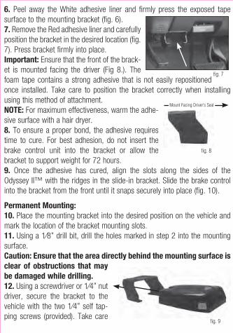
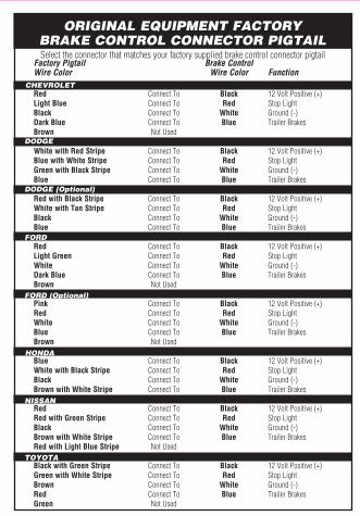
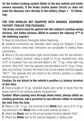
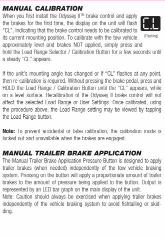
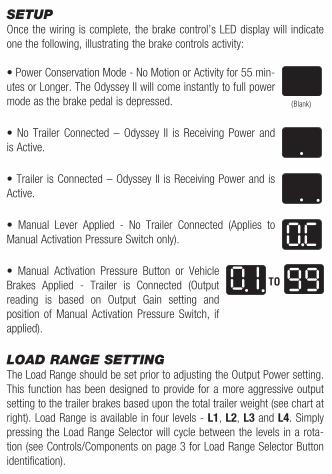
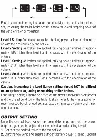
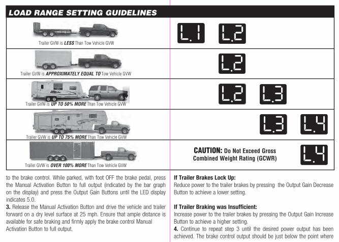
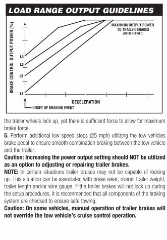
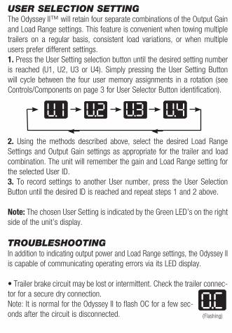
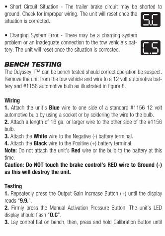
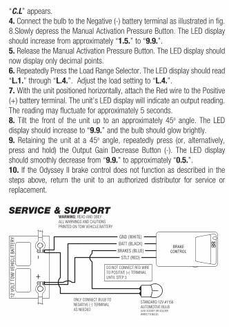


![Index [ptgmedia.pearsoncmg.com]ptgmedia.pearsoncmg.com/.../samplechapter/0321278542_Index.pdf · / character, 1156, 1533 ^ character, ... Accelerometer data, 1297–1303 Accent, 17–18,](https://img.pdfslide.net/doc/110x75/5b4fe1c87f8b9a5a6f8d56a9/index-character-1156-1533-character-accelerometer-data-12971303.jpg)