Embed Size (px)
Citation preview
11 General-Purpose Timers
Programmable timers can be used to count or time external events that drive the Timer input pins.
The TM4C123GH6PMGeneral-Purpose Timer Module (GPTM) contains six 16/32-bit GPTM blocks
and six 32/64-bit Wide GPTM blocks. Each 16/32-bit GPTM block provides two 16-bit timers/counters
(referred to as Timer A and Timer B) that can be configured to operate independently as timers or
event counters, or concatenated to operate as one 32-bit timer or one 32-bit Real-Time Clock (RTC).
Each 32/64-bit Wide GPTM block provides 32-bit timers for Timer A and Timer B that can be
concatenated to operate as a 64-bit timer. Timers can also be used to trigger μDMA transfers.
In addition, timers can be used to trigger analog-to-digital conversions (ADC) when a time-out occurs
in periodic and one-shot modes. The ADC trigger signals from all of the general-purpose timers are
ORed together before reaching the ADC module, so only one timer should be used to trigger ADC
events.
The GPT Module is one timing resource available on the Tiva™ C Series microcontrollers. Other
timer resources include the System Timer (SysTick) (see 123) and the PWM timer in the PWM
modules (see “PWM Timer” on page 1234).
The General-Purpose Timer Module (GPTM) contains six 16/32-bit GPTM blocks and six 32/64-bit
Wide GPTM blocks with the following functional options:
■ 16/32-bit operating modes:
– 16- or 32-bit programmable one-shot timer
– 16- or 32-bit programmable periodic timer
– 16-bit general-purpose timer with an 8-bit prescaler
– 32-bit Real-Time Clock (RTC) when using an external 32.768-KHz clock as the input
– 16-bit input-edge count- or time-capture modes with an 8-bit prescaler
– 16-bit PWMmode with an 8-bit prescaler and software-programmable output inversion of the
PWM signal
■ 32/64-bit operating modes:
– 32- or 64-bit programmable one-shot timer
– 32- or 64-bit programmable periodic timer
– 32-bit general-purpose timer with a 16-bit prescaler
– 64-bit Real-Time Clock (RTC) when using an external 32.768-KHz clock as the input
– 32-bit input-edge count- or time-capture modes with a16-bit prescaler
– 32-bit PWMmode with a 16-bit prescaler and software-programmable output inversion of the
PWM signal
■ Count up or down
■ Twelve 16/32-bit Capture Compare PWM pins (CCP)
June 12, 2014704
Texas Instruments-Production Data
General-Purpose Timers
■ Twelve 32/64-bit Capture Compare PWM pins (CCP)
■ Daisy chaining of timer modules to allow a single timer to initiate multiple timing events
■ Timer synchronization allows selected timers to start counting on the same clock cycle
■ ADC event trigger
■ User-enabled stalling when the microcontroller asserts CPU Halt flag during debug (excluding
RTC mode)
■ Ability to determine the elapsed time between the assertion of the timer interrupt and entry into
the interrupt service routine
■ Efficient transfers using Micro Direct Memory Access Controller (µDMA)
– Dedicated channel for each timer
– Burst request generated on timer interrupt
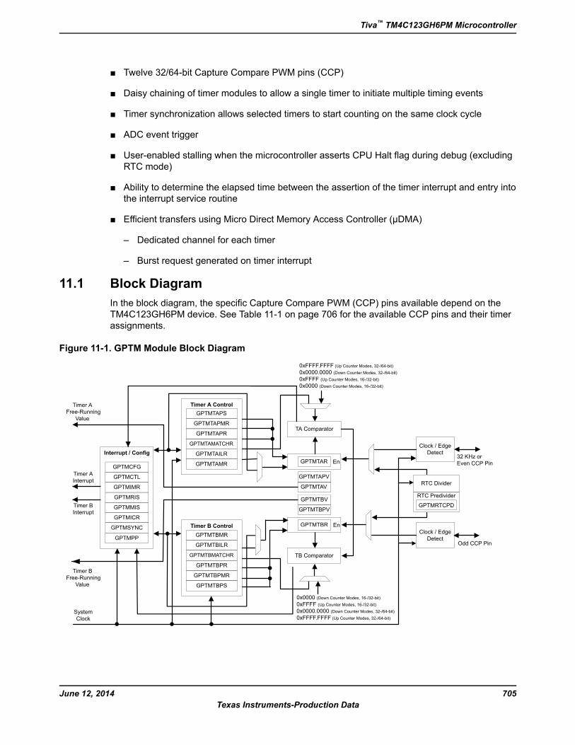
11.1 Block Diagram
In the block diagram, the specific Capture Compare PWM (CCP) pins available depend on the
TM4C123GH6PM device. See Table 11-1 on page 706 for the available CCP pins and their timer
assignments.
Figure 11-1. GPTM Module Block Diagram
Clock / Edge
Detect
RTC Divider
Clock / Edge
Detect32 KHz or
Even CCP Pin
Odd CCP Pin
TA Comparator
TB Comparator
GPTMTBR
GPTMTAR
Timer A
Interrupt
Timer B
Interrupt
System
Clock
En
En
Interrupt / Config
GPTMCFG
GPTMRIS
GPTMICR
GPTMMIS
GPTMIMR
GPTMCTL
GPTMTBR
GPTMTARGPTMTGPTMT
GPTMTAV
GPTMTBV
Timer A
Free-Running
Value
Timer B
Free-Running
Value
Timer A Control
GPTMTAPMR
GPTMTAILR
GPTMTAMATCHR
GPTMTAPR
GPTMTAMR
Timer B Control
GPTMTBPMR
GPTMTBILR
GPTMTBMATCHR
GPTMTBPR
GPTMTBMR
GPTMTAPS
GPTMTBPS
GPTMTAPV
GPTMTBPV
RTC Predivider
GPTMRTCPD
0x0000 (Down Counter Modes, 16-/32-bit)
0xFFFF (Up Counter Modes, 16-/32-bit)
0x0000.0000 (Down Counter Modes, 32-/64-bit)
0xFFFF.FFFF (Up Counter Modes, 32-/64-bit)
0xFFFF.FFFF (Up Counter Modes, 32-/64-bit)
0x0000.0000 (Down Counter Modes, 32-/64-bit)
0xFFFF (Up Counter Modes, 16-/32-bit)
0x0000 (Down Counter Modes, 16-/32-bit)
GPTMSYNC
GPTMPP
705June 12, 2014
Texas Instruments-Production Data
Tiva™ TM4C123GH6PM Microcontroller
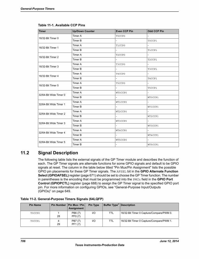
Table 11-1. Available CCP Pins
Odd CCP PinEven CCP PinUp/Down CounterTimer
-T0CCP0Timer A16/32-Bit Timer 0
T0CCP1-Timer B
-T1CCP0Timer A16/32-Bit Timer 1
T1CCP1-Timer B
-T2CCP0Timer A16/32-Bit Timer 2
T2CCP1-Timer B
-T3CCP0Timer A16/32-Bit Timer 3
T3CCP1-Timer B
-T4CCP0Timer A16/32-Bit Timer 4
T4CCP1-Timer B
-T5CCP0Timer A16/32-Bit Timer 5
T5CCP1-Timer B
-WT0CCP0Timer A32/64-Bit Wide Timer 0
WT0CCP1-Timer B
-WT1CCP0Timer A32/64-Bit Wide Timer 1
WT1CCP1-Timer B
-WT2CCP0Timer A32/64-Bit Wide Timer 2
WT2CCP1-Timer B
-WT3CCP0Timer A32/64-Bit Wide Timer 3
WT3CCP1-Timer B
-WT4CCP0Timer A32/64-Bit Wide Timer 4
WT4CCP1-Timer B
-WT5CCP0Timer A32/64-Bit Wide Timer 5
WT5CCP1-Timer B
11.2 Signal Description
The following table lists the external signals of the GP Timer module and describes the function of
each. The GP Timer signals are alternate functions for some GPIO signals and default to be GPIO
signals at reset. The column in the table below titled "Pin Mux/Pin Assignment" lists the possible
GPIO pin placements for these GP Timer signals. The AFSEL bit in the GPIO Alternate Function
Select (GPIOAFSEL) register (page 671) should be set to choose the GP Timer function. The number
in parentheses is the encoding that must be programmed into the PMCn field in the GPIO Port
Control (GPIOPCTL) register (page 688) to assign the GP Timer signal to the specified GPIO port
pin. For more information on configuring GPIOs, see “General-Purpose Input/Outputs
(GPIOs)” on page 649.
Table 11-2. General-Purpose Timers Signals (64LQFP)
DescriptionBuffer Typea
Pin TypePin Mux / Pin
Assignment
Pin NumberPin Name
16/32-Bit Timer 0 Capture/Compare/PWM 0.TTLI/OPB6 (7)
PF0 (7)
1
28
T0CCP0
16/32-Bit Timer 0 Capture/Compare/PWM 1.TTLI/OPB7 (7)
PF1 (7)
4
29
T0CCP1
June 12, 2014706
Texas Instruments-Production Data
General-Purpose Timers
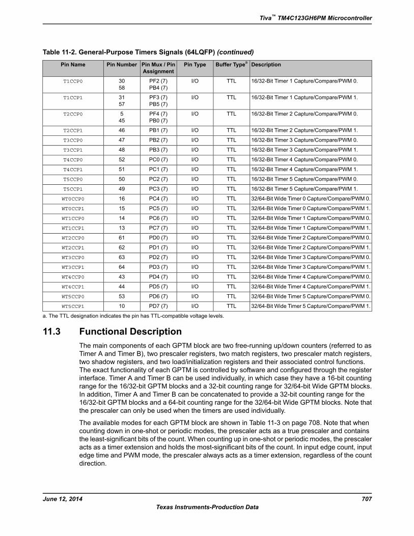
Table 11-2. General-Purpose Timers Signals (64LQFP) (continued)
DescriptionBuffer Typea
Pin TypePin Mux / Pin
Assignment
Pin NumberPin Name
16/32-Bit Timer 1 Capture/Compare/PWM 0.TTLI/OPF2 (7)
PB4 (7)
30
58
T1CCP0
16/32-Bit Timer 1 Capture/Compare/PWM 1.TTLI/OPF3 (7)
PB5 (7)
31
57
T1CCP1
16/32-Bit Timer 2 Capture/Compare/PWM 0.TTLI/OPF4 (7)
PB0 (7)
5
45
T2CCP0
16/32-Bit Timer 2 Capture/Compare/PWM 1.TTLI/OPB1 (7)46T2CCP1
16/32-Bit Timer 3 Capture/Compare/PWM 0.TTLI/OPB2 (7)47T3CCP0
16/32-Bit Timer 3 Capture/Compare/PWM 1.TTLI/OPB3 (7)48T3CCP1
16/32-Bit Timer 4 Capture/Compare/PWM 0.TTLI/OPC0 (7)52T4CCP0
16/32-Bit Timer 4 Capture/Compare/PWM 1.TTLI/OPC1 (7)51T4CCP1
16/32-Bit Timer 5 Capture/Compare/PWM 0.TTLI/OPC2 (7)50T5CCP0
16/32-Bit Timer 5 Capture/Compare/PWM 1.TTLI/OPC3 (7)49T5CCP1
32/64-Bit Wide Timer 0 Capture/Compare/PWM 0.TTLI/OPC4 (7)16WT0CCP0
32/64-Bit Wide Timer 0 Capture/Compare/PWM 1.TTLI/OPC5 (7)15WT0CCP1
32/64-Bit Wide Timer 1 Capture/Compare/PWM 0.TTLI/OPC6 (7)14WT1CCP0
32/64-Bit Wide Timer 1 Capture/Compare/PWM 1.TTLI/OPC7 (7)13WT1CCP1
32/64-Bit Wide Timer 2 Capture/Compare/PWM 0.TTLI/OPD0 (7)61WT2CCP0
32/64-Bit Wide Timer 2 Capture/Compare/PWM 1.TTLI/OPD1 (7)62WT2CCP1
32/64-Bit Wide Timer 3 Capture/Compare/PWM 0.TTLI/OPD2 (7)63WT3CCP0
32/64-Bit Wide Timer 3 Capture/Compare/PWM 1.TTLI/OPD3 (7)64WT3CCP1
32/64-Bit Wide Timer 4 Capture/Compare/PWM 0.TTLI/OPD4 (7)43WT4CCP0
32/64-Bit Wide Timer 4 Capture/Compare/PWM 1.TTLI/OPD5 (7)44WT4CCP1
32/64-Bit Wide Timer 5 Capture/Compare/PWM 0.TTLI/OPD6 (7)53WT5CCP0
32/64-Bit Wide Timer 5 Capture/Compare/PWM 1.TTLI/OPD7 (7)10WT5CCP1
a. The TTL designation indicates the pin has TTL-compatible voltage levels.
11.3 Functional Description
The main components of each GPTM block are two free-running up/down counters (referred to as
Timer A and Timer B), two prescaler registers, two match registers, two prescaler match registers,
two shadow registers, and two load/initialization registers and their associated control functions.
The exact functionality of each GPTM is controlled by software and configured through the register
interface. Timer A and Timer B can be used individually, in which case they have a 16-bit counting
range for the 16/32-bit GPTM blocks and a 32-bit counting range for 32/64-bit Wide GPTM blocks.
In addition, Timer A and Timer B can be concatenated to provide a 32-bit counting range for the
16/32-bit GPTM blocks and a 64-bit counting range for the 32/64-bit Wide GPTM blocks. Note that
the prescaler can only be used when the timers are used individually.
The available modes for each GPTM block are shown in Table 11-3 on page 708. Note that when
counting down in one-shot or periodic modes, the prescaler acts as a true prescaler and contains
the least-significant bits of the count. When counting up in one-shot or periodic modes, the prescaler
acts as a timer extension and holds the most-significant bits of the count. In input edge count, input
edge time and PWM mode, the prescaler always acts as a timer extension, regardless of the count
direction.
707June 12, 2014
Texas Instruments-Production Data
Tiva™ TM4C123GH6PM Microcontroller
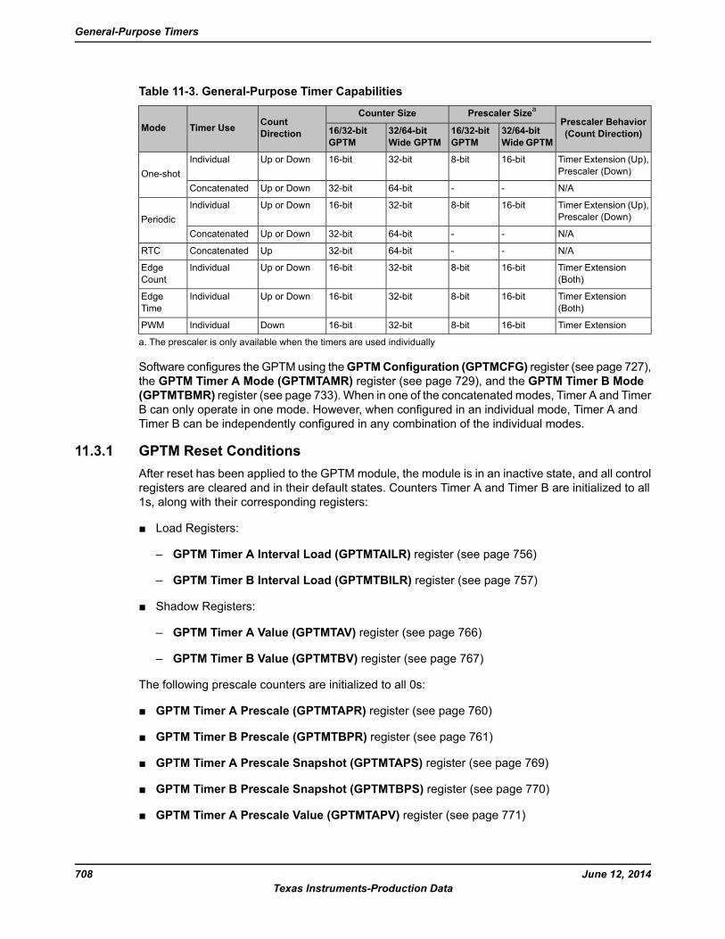
Table 11-3. General-Purpose Timer Capabilities
Prescaler Behavior
(Count Direction)
Prescaler Sizea
Counter SizeCount
DirectionTimer UseMode 32/64-bit
WideGPTM
16/32-bit
GPTM
32/64-bit
Wide GPTM
16/32-bit
GPTM
Timer Extension (Up),
Prescaler (Down)
16-bit8-bit32-bit16-bitUp or DownIndividual
One-shot
N/A--64-bit32-bitUp or DownConcatenated
Timer Extension (Up),
Prescaler (Down)
16-bit8-bit32-bit16-bitUp or DownIndividual
Periodic
N/A--64-bit32-bitUp or DownConcatenated
N/A--64-bit32-bitUpConcatenatedRTC
Timer Extension
(Both)
16-bit8-bit32-bit16-bitUp or DownIndividualEdge
Count
Timer Extension
(Both)
16-bit8-bit32-bit16-bitUp or DownIndividualEdge
Time
Timer Extension16-bit8-bit32-bit16-bitDownIndividualPWM
a. The prescaler is only available when the timers are used individually
Software configures the GPTM using theGPTMConfiguration (GPTMCFG) register (see page 727),
the GPTM Timer A Mode (GPTMTAMR) register (see page 729), and the GPTM Timer B Mode
(GPTMTBMR) register (see page 733). When in one of the concatenatedmodes, Timer A and Timer
B can only operate in one mode. However, when configured in an individual mode, Timer A and
Timer B can be independently configured in any combination of the individual modes.
11.3.1 GPTM Reset Conditions
After reset has been applied to the GPTM module, the module is in an inactive state, and all control
registers are cleared and in their default states. Counters Timer A and Timer B are initialized to all
1s, along with their corresponding registers:
■ Load Registers:
– GPTM Timer A Interval Load (GPTMTAILR) register (see page 756)
– GPTM Timer B Interval Load (GPTMTBILR) register (see page 757)
■ Shadow Registers:
– GPTM Timer A Value (GPTMTAV) register (see page 766)
– GPTM Timer B Value (GPTMTBV) register (see page 767)
The following prescale counters are initialized to all 0s:
■ GPTM Timer A Prescale (GPTMTAPR) register (see page 760)
■ GPTM Timer B Prescale (GPTMTBPR) register (see page 761)
■ GPTM Timer A Prescale Snapshot (GPTMTAPS) register (see page 769)
■ GPTM Timer B Prescale Snapshot (GPTMTBPS) register (see page 770)
■ GPTM Timer A Prescale Value (GPTMTAPV) register (see page 771)
June 12, 2014708
Texas Instruments-Production Data
General-Purpose Timers
■ GPTM Timer B Prescale Value (GPTMTBPV) register (see page 772)
11.3.2 Timer Modes
This section describes the operation of the various timer modes. When using Timer A and Timer B
in concatenated mode, only the Timer A control and status bits must be used; there is no need to
use Timer B control and status bits. The GPTM is placed into individual/split mode by writing a value
of 0x4 to the GPTM Configuration (GPTMCFG) register (see page 727). In the following sections,
the variable "n" is used in bit field and register names to imply either a Timer A function or a TimerB function. Throughout this section, the timeout event in down-count mode is 0x0 and in up-count
mode is the value in theGPTM Timer n Interval Load (GPTMTnILR) and the optionalGPTM Timer
n Prescale (GPTMTnPR) registers, with the exception of RTC mode.
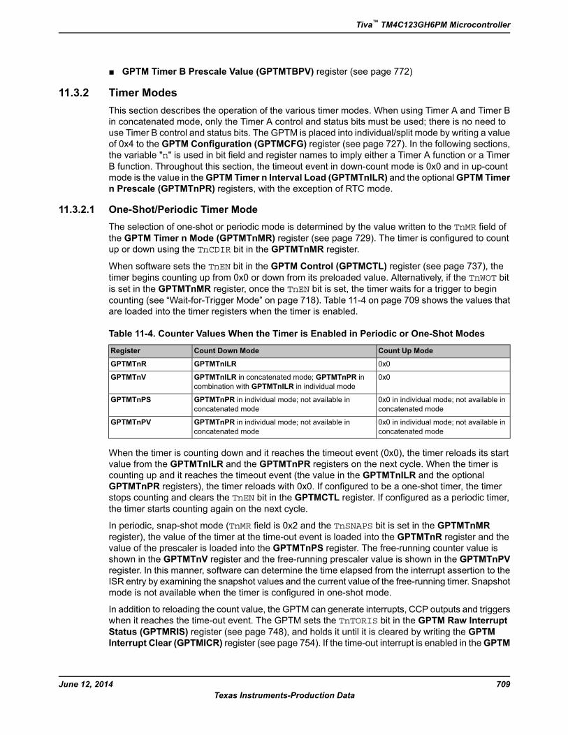
11.3.2.1 One-Shot/Periodic Timer Mode
The selection of one-shot or periodic mode is determined by the value written to the TnMR field ofthe GPTM Timer n Mode (GPTMTnMR) register (see page 729). The timer is configured to count
up or down using the TnCDIR bit in the GPTMTnMR register.
When software sets the TnEN bit in the GPTM Control (GPTMCTL) register (see page 737), the
timer begins counting up from 0x0 or down from its preloaded value. Alternatively, if the TnWOT bitis set in the GPTMTnMR register, once the TnEN bit is set, the timer waits for a trigger to begincounting (see “Wait-for-Trigger Mode” on page 718). Table 11-4 on page 709 shows the values that
are loaded into the timer registers when the timer is enabled.
Table 11-4. Counter Values When the Timer is Enabled in Periodic or One-Shot Modes
Count Up ModeCount Down ModeRegister
0x0GPTMTnILRGPTMTnR
0x0GPTMTnILR in concatenated mode; GPTMTnPR in
combination with GPTMTnILR in individual mode
GPTMTnV
0x0 in individual mode; not available in
concatenated mode
GPTMTnPR in individual mode; not available in
concatenated mode
GPTMTnPS
0x0 in individual mode; not available in
concatenated mode
GPTMTnPR in individual mode; not available in
concatenated mode
GPTMTnPV
When the timer is counting down and it reaches the timeout event (0x0), the timer reloads its start
value from the GPTMTnILR and the GPTMTnPR registers on the next cycle. When the timer is
counting up and it reaches the timeout event (the value in the GPTMTnILR and the optional
GPTMTnPR registers), the timer reloads with 0x0. If configured to be a one-shot timer, the timer
stops counting and clears the TnEN bit in the GPTMCTL register. If configured as a periodic timer,
the timer starts counting again on the next cycle.
In periodic, snap-shot mode (TnMR field is 0x2 and the TnSNAPS bit is set in the GPTMTnMR
register), the value of the timer at the time-out event is loaded into the GPTMTnR register and the
value of the prescaler is loaded into the GPTMTnPS register. The free-running counter value is
shown in the GPTMTnV register and the free-running prescaler value is shown in the GPTMTnPV
register. In this manner, software can determine the time elapsed from the interrupt assertion to the
ISR entry by examining the snapshot values and the current value of the free-running timer. Snapshot
mode is not available when the timer is configured in one-shot mode.
In addition to reloading the count value, the GPTM can generate interrupts, CCP outputs and triggers
when it reaches the time-out event. The GPTM sets the TnTORIS bit in the GPTM Raw Interrupt
Status (GPTMRIS) register (see page 748), and holds it until it is cleared by writing the GPTM
Interrupt Clear (GPTMICR) register (see page 754). If the time-out interrupt is enabled in theGPTM
709June 12, 2014
Texas Instruments-Production Data
Tiva™ TM4C123GH6PM Microcontroller

Interrupt Mask (GPTMIMR) register (see page 745), the GPTM also sets the TnTOMIS bit in theGPTM Masked Interrupt Status (GPTMMIS) register (see page 751).
By setting the TnMIE bit in the GPTMTnMR register, an interrupt condition can also be generated
when the Timer value equals the value loaded into the GPTM Timer n Match (GPTMTnMATCHR)
and GPTM Timer n Prescale Match (GPTMTnPMR) registers. This interrupt has the same status,
masking, and clearing functions as the time-out interrupt, but uses the match interrupt bits instead
(for example, the raw interrupt status is monitored via TnMRIS bit in theGPTMRaw Interrupt Status
(GPTMRIS) register). Note that the interrupt status bits are not updated by the hardware unless the
TnMIE bit in the GPTMTnMR register is set, which is different than the behavior for the time-out
interrupt. The ADC trigger is enabled by setting the TnOTE bit in GPTMCTL. If the ADC trigger is
enabled, only a one-shot or periodic time-out event can produce an ADC trigger assertion. The
μDMA trigger is enabled by configuring and enabling the appropriate μDMA channel. See “Channel
Configuration” on page 589.
If software updates theGPTMTnILR or theGPTMTnPR register while the counter is counting down,
the counter loads the new value on the next clock cycle and continues counting from the new value
if the TnILD bit in the GPTMTnMR register is clear. If the TnILD bit is set, the counter loads thenew value after the next timeout. If software updates the GPTMTnILR or the GPTMTnPR register
while the counter is counting up, the timeout event is changed on the next cycle to the new value.
If software updates the GPTM Timer n Value (GPTMTnV) register while the counter is counting up
or down, the counter loads the new value on the next clock cycle and continues counting from the
new value. If software updates theGPTMTnMATCHR or theGPTMTnPMR registers, the new values
are reflected on the next clock cycle if the TnMRSU bit in the GPTMTnMR register is clear. If the
TnMRSU bit is set, the new value will not take effect until the next timeout.
When using a 32/64-bit wide timer block in a 64-bit mode, certain registers must be accessed in the
manner described in “Accessing Concatenated 32/64-Bit Wide GPTMRegister Values” on page 720.
If the TnSTALL bit in the GPTMCTL register is set and the RTCEN bit is not set in the GPTMCTL
register, the timer freezes counting while the processor is halted by the debugger. The timer resumes
counting when the processor resumes execution. If the RTCEN bit is set, it prevents the TnSTALLbit from freezing the count when the processor is halted by the debugger.
The following table shows a variety of configurations for a 16-bit free-running timer while using the
prescaler. All values assume an 80-MHz clock with Tc=12.5 ns (clock period). The prescaler can
only be used when a 16/32-bit timer is configured in 16-bit mode and when a 32/64-bit timer is
configured in 32-bit mode.
Table 11-5. 16-Bit Timer With Prescaler Configurations
UnitsMax Time# of Timer Clocks (Tc)a
Prescale (8-bit value)
ms0.8192100000000
ms1.6384200000001
ms2.4576300000010
------------------
ms208.076825411111101
ms208.89625511111110
ms209.715225611111111
a. Tc is the clock period.
The following table shows a variety of configurations for a 32-bit free-running timer using the prescaler
while configured in 32/64-bit mode. All values assume an 80-MHz clock with Tc=12.5 ns (clock
period).
June 12, 2014710
Texas Instruments-Production Data
General-Purpose Timers
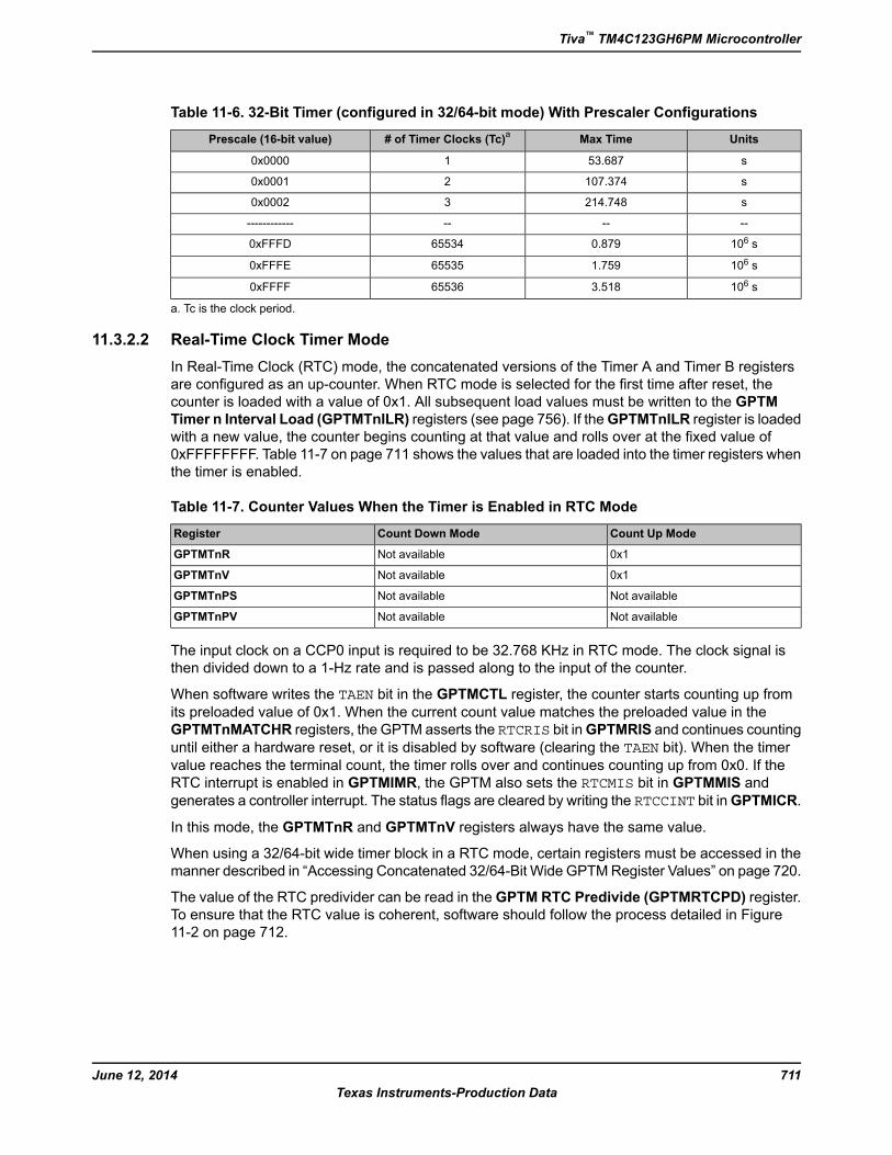
Table 11-6. 32-Bit Timer (configured in 32/64-bit mode) With Prescaler Configurations
UnitsMax Time# of Timer Clocks (Tc)a
Prescale (16-bit value)
s53.68710x0000
s107.37420x0001
s214.74830x0002
------------------
106 s0.879655340xFFFD
106 s1.759655350xFFFE
106 s3.518655360xFFFF
a. Tc is the clock period.
11.3.2.2 Real-Time Clock Timer Mode
In Real-Time Clock (RTC) mode, the concatenated versions of the Timer A and Timer B registers
are configured as an up-counter. When RTC mode is selected for the first time after reset, the
counter is loaded with a value of 0x1. All subsequent load values must be written to the GPTM
Timer n Interval Load (GPTMTnILR) registers (see page 756). If theGPTMTnILR register is loaded
with a new value, the counter begins counting at that value and rolls over at the fixed value of
0xFFFFFFFF. Table 11-7 on page 711 shows the values that are loaded into the timer registers when
the timer is enabled.
Table 11-7. Counter Values When the Timer is Enabled in RTC Mode
Count Up ModeCount Down ModeRegister
0x1Not availableGPTMTnR
0x1Not availableGPTMTnV
Not availableNot availableGPTMTnPS
Not availableNot availableGPTMTnPV
The input clock on a CCP0 input is required to be 32.768 KHz in RTC mode. The clock signal is
then divided down to a 1-Hz rate and is passed along to the input of the counter.
When software writes the TAEN bit in the GPTMCTL register, the counter starts counting up from
its preloaded value of 0x1. When the current count value matches the preloaded value in the
GPTMTnMATCHR registers, the GPTM asserts the RTCRIS bit inGPTMRIS and continues counting
until either a hardware reset, or it is disabled by software (clearing the TAEN bit). When the timervalue reaches the terminal count, the timer rolls over and continues counting up from 0x0. If the
RTC interrupt is enabled in GPTMIMR, the GPTM also sets the RTCMIS bit in GPTMMIS and
generates a controller interrupt. The status flags are cleared by writing the RTCCINT bit inGPTMICR.
In this mode, the GPTMTnR and GPTMTnV registers always have the same value.
When using a 32/64-bit wide timer block in a RTC mode, certain registers must be accessed in the
manner described in “Accessing Concatenated 32/64-Bit Wide GPTMRegister Values” on page 720.
The value of the RTC predivider can be read in theGPTM RTC Predivide (GPTMRTCPD) register.
To ensure that the RTC value is coherent, software should follow the process detailed in Figure
11-2 on page 712.
711June 12, 2014
Texas Instruments-Production Data
Tiva™ TM4C123GH6PM Microcontroller
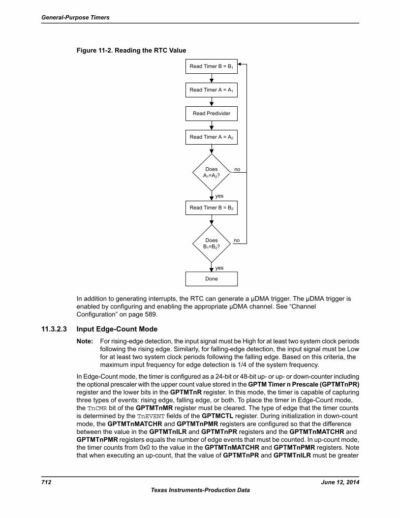
Figure 11-2. Reading the RTC Value
Read Timer B = B1
Read Timer A = A1
Read Predivider
Read Timer A = A2
Does
A1=A2?
Done
no
no
Done
yes
yes
Does
B1=B2?
Read Timer B = B2
In addition to generating interrupts, the RTC can generate a μDMA trigger. The μDMA trigger is
enabled by configuring and enabling the appropriate μDMA channel. See “Channel
Configuration” on page 589.
11.3.2.3 Input Edge-Count Mode
Note: For rising-edge detection, the input signal must be High for at least two system clock periods
following the rising edge. Similarly, for falling-edge detection, the input signal must be Low
for at least two system clock periods following the falling edge. Based on this criteria, the
maximum input frequency for edge detection is 1/4 of the system frequency.
In Edge-Count mode, the timer is configured as a 24-bit or 48-bit up- or up- or down-counter including
the optional prescaler with the upper count value stored in theGPTMTimer n Prescale (GPTMTnPR)
register and the lower bits in the GPTMTnR register. In this mode, the timer is capable of capturing
three types of events: rising edge, falling edge, or both. To place the timer in Edge-Count mode,
the TnCMR bit of the GPTMTnMR register must be cleared. The type of edge that the timer counts
is determined by the TnEVENT fields of the GPTMCTL register. During initialization in down-count
mode, the GPTMTnMATCHR and GPTMTnPMR registers are configured so that the difference
between the value in the GPTMTnILR and GPTMTnPR registers and the GPTMTnMATCHR and
GPTMTnPMR registers equals the number of edge events that must be counted. In up-count mode,
the timer counts from 0x0 to the value in the GPTMTnMATCHR and GPTMTnPMR registers. Note
that when executing an up-count, that the value of GPTMTnPR and GPTMTnILR must be greater
June 12, 2014712
Texas Instruments-Production Data
General-Purpose Timers
than the value of GPTMTnPMR and GPTMTnMATCHR. Table 11-8 on page 713 shows the values
that are loaded into the timer registers when the timer is enabled.
Table 11-8. Counter Values When the Timer is Enabled in Input Edge-Count Mode
Count Up ModeCount Down ModeRegister
0x0GPTMTnPR in combination with GPTMTnILRGPTMTnR
0x0GPTMTnPR in combination with GPTMTnILRGPTMTnV
0x0GPTMTnPRGPTMTnPS
0x0GPTMTnPRGPTMTnPV
When software writes the TnEN bit in the GPTM Control (GPTMCTL) register, the timer is enabled
for event capture. Each input event on the CCP pin decrements or increments the counter by 1 until
the event count matchesGPTMTnMATCHR andGPTMTnPMR. When the countsmatch, theGPTM
asserts the CnMRIS bit in the GPTM Raw Interrupt Status (GPTMRIS) register, and holds it until
it is cleared by writing the GPTM Interrupt Clear (GPTMICR) register. If the capture mode match
interrupt is enabled in the GPTM Interrupt Mask (GPTMIMR) register, the GPTM also sets the
CnMMIS bit in theGPTMMasked Interrupt Status (GPTMMIS) register. In this mode, theGPTMTnR
and GPTMTnPS registers hold the count of the input events while the GPTMTnV and GPTMTnPV
registers hold the free-running timer value and the free-running prescaler value.In up count mode,
the current count of input events is held in both the GPTMTnR and GPTMTnV registers.
In addition to generating interrupts, a μDMA trigger can be generated. The μDMA trigger is enabled
by configuring and enabling the appropriate μDMA channel. See “Channel Configuration” on page 589.
After the match value is reached in down-count mode, the counter is then reloaded using the value
in GPTMTnILR and GPTMTnPR registers, and stopped because the GPTM automatically clears
the TnEN bit in the GPTMCTL register. Once the event count has been reached, all further events
are ignored until TnEN is re-enabled by software. In up-count mode, the timer is reloaded with 0x0and continues counting.
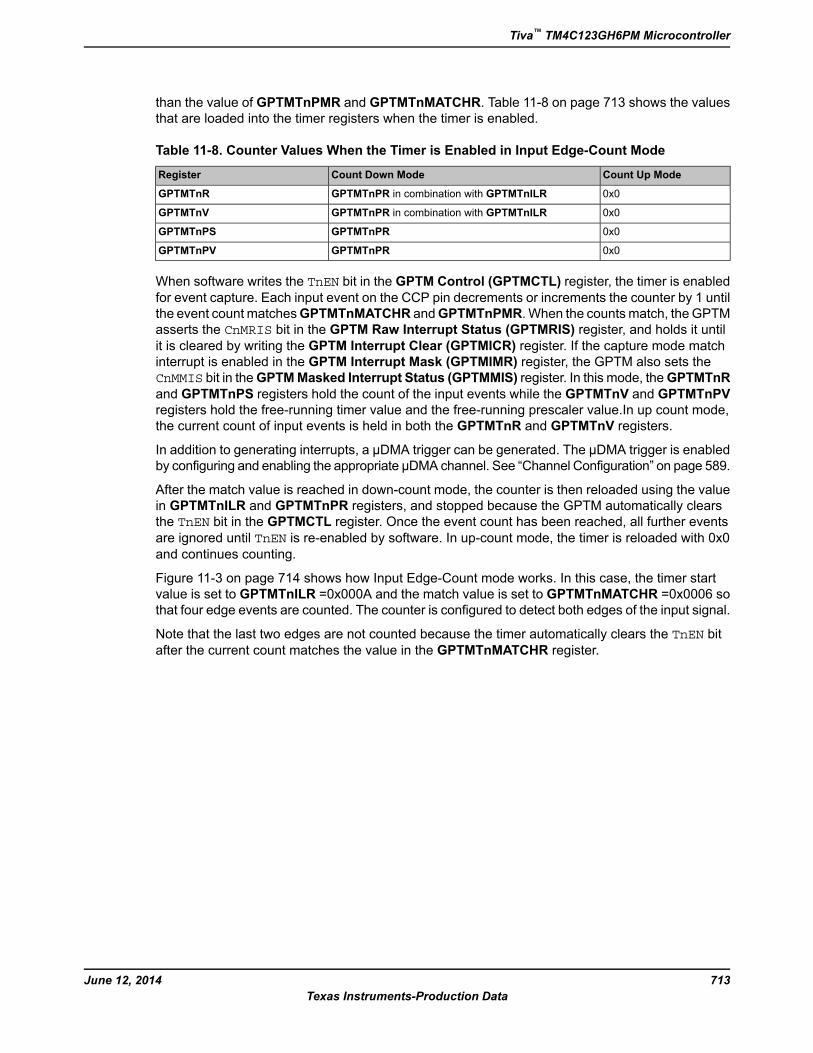
Figure 11-3 on page 714 shows how Input Edge-Count mode works. In this case, the timer start
value is set to GPTMTnILR =0x000A and the match value is set to GPTMTnMATCHR =0x0006 so
that four edge events are counted. The counter is configured to detect both edges of the input signal.
Note that the last two edges are not counted because the timer automatically clears the TnEN bitafter the current count matches the value in the GPTMTnMATCHR register.
713June 12, 2014
Texas Instruments-Production Data
Tiva™ TM4C123GH6PM Microcontroller
Figure 11-3. Input Edge-Count Mode Example, Counting Down
Input Signal
Timer stops,
flags
asserted
Timer reload
on next cycle Ignored IgnoredCount
0x000A
0x0006
0x0007
0x0008
0x0009
11.3.2.4 Input Edge-Time Mode
Note: For rising-edge detection, the input signal must be High for at least two system clock periods
following the rising edge. Similarly, for falling edge detection, the input signal must be Low
for at least two system clock periods following the falling edge. Based on this criteria, the
maximum input frequency for edge detection is 1/4 of the system frequency.
In Edge-Time mode, the timer is configured as a 24-bit or 48-bit up- or down-counter including the
optional prescaler with the upper timer value stored in the GPTMTnPR register and the lower bits
in theGPTMTnILR register. In this mode, the timer is initialized to the value loaded in theGPTMTnILR
and GPTMTnPR registers when counting down and 0x0 when counting up. The timer is capable of
capturing three types of events: rising edge, falling edge, or both. The timer is placed into Edge-Time
mode by setting the TnCMR bit in the GPTMTnMR register, and the type of event that the timer
captures is determined by the TnEVENT fields of the GPTMCTL register. Table 11-9 on page 714
shows the values that are loaded into the timer registers when the timer is enabled.
Table 11-9. Counter Values When the Timer is Enabled in Input Event-Count Mode
Count Up ModeCount Down ModeRegister
0x0GPTMTnILRTnR
0x0GPTMTnILRTnV
0x0GPTMTnPRTnPS
0x0GPTMTnPRTnPV
When software writes the TnEN bit in theGPTMCTL register, the timer is enabled for event capture.
When the selected input event is detected, the current timer counter value is captured in the
GPTMTnR and GPTMTnPS register and is available to be read by the microcontroller. The GPTM
then asserts the CnERIS bit in the GPTM Raw Interrupt Status (GPTMRIS) register, and holds it
until it is cleared by writing the GPTM Interrupt Clear (GPTMICR) register. If the capture mode
event interrupt is enabled in the GPTM Interrupt Mask (GPTMIMR) register, the GPTM also sets
the CnEMIS bit in the GPTM Masked Interrupt Status (GPTMMIS) register. In this mode, the
June 12, 2014714
Texas Instruments-Production Data
General-Purpose Timers
GPTMTnR andGPTMTnPS registers hold the time at which the selected input event occurred while
the GPTMTnV and GPTMTnPV registers hold the free-running timer value and the free-running
prescaler value. These registers can be read to determine the time that elapsed between the interrupt
assertion and the entry into the ISR.
In addition to generating interrupts, a μDMA trigger can be generated. The μDMA trigger is enabled
by configuring the appropriate μDMA channel. See “Channel Configuration” on page 589.
After an event has been captured, the timer does not stop counting. It continues to count until the
TnEN bit is cleared. When the timer reaches the timeout value, it is reloaded with 0x0 in up-countmode and the value from the GPTMTnILR and GPTMTnPR registers in down-count mode.
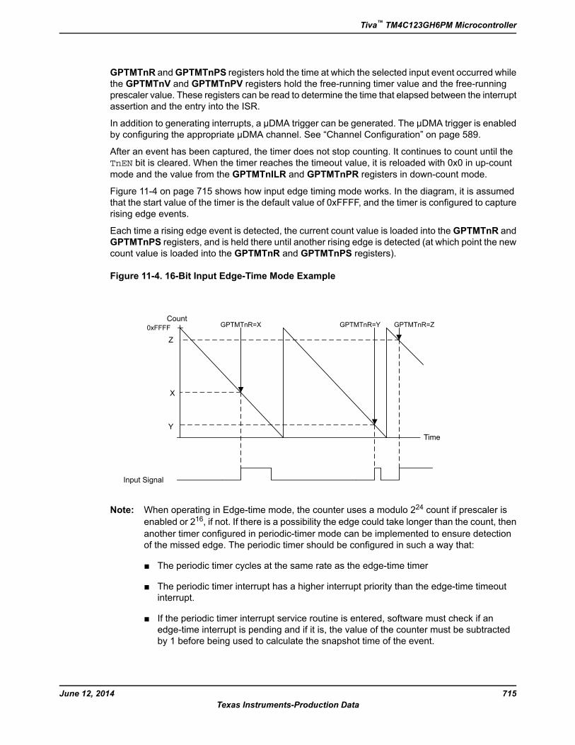
Figure 11-4 on page 715 shows how input edge timing mode works. In the diagram, it is assumed
that the start value of the timer is the default value of 0xFFFF, and the timer is configured to capture
rising edge events.
Each time a rising edge event is detected, the current count value is loaded into the GPTMTnR and
GPTMTnPS registers, and is held there until another rising edge is detected (at which point the new
count value is loaded into the GPTMTnR and GPTMTnPS registers).
Figure 11-4. 16-Bit Input Edge-Time Mode Example
GPTMTnR=Y
Input Signal
Time
CountGPTMTnR=X GPTMTnR=Z
Z
X
Y
0xFFFF
Note: When operating in Edge-time mode, the counter uses a modulo 224 count if prescaler is
enabled or 216, if not. If there is a possibility the edge could take longer than the count, then
another timer configured in periodic-timer mode can be implemented to ensure detection
of the missed edge. The periodic timer should be configured in such a way that:
■ The periodic timer cycles at the same rate as the edge-time timer
■ The periodic timer interrupt has a higher interrupt priority than the edge-time timeout
interrupt.
■ If the periodic timer interrupt service routine is entered, software must check if an
edge-time interrupt is pending and if it is, the value of the counter must be subtracted
by 1 before being used to calculate the snapshot time of the event.
715June 12, 2014
Texas Instruments-Production Data
Tiva™ TM4C123GH6PM Microcontroller
11.3.2.5 PWM Mode
The GPTM supports a simple PWM generation mode. In PWM mode, the timer is configured as a
24-bit or 48-bit down-counter with a start value (and thus period) defined by the GPTMTnILR and
GPTMTnPR registers. In this mode, the PWM frequency and period are synchronous events and
therefore guaranteed to be glitch free. PWM mode is enabled with the GPTMTnMR register by
setting the TnAMS bit to 0x1, the TnCMR bit to 0x0, and the TnMR field to 0x2. Table 11-10 on page 716shows the values that are loaded into the timer registers when the timer is enabled.
Table 11-10. Counter Values When the Timer is Enabled in PWM Mode
Count Up ModeCount Down ModeRegister
Not availableGPTMTnILRGPTMTnR
Not availableGPTMTnILRGPTMTnV
Not availableGPTMTnPRGPTMTnPS
Not availableGPTMTnPRGPTMTnPV
When software writes the TnEN bit in the GPTMCTL register, the counter begins counting down
until it reaches the 0x0 state. Alternatively, if the TnWOT bit is set in the GPTMTnMR register, once
the TnEN bit is set, the timer waits for a trigger to begin counting (see “Wait-for-TriggerMode” on page 718). On the next counter cycle in periodic mode, the counter reloads its start value
from the GPTMTnILR and GPTMTnPR registers and continues counting until disabled by software
clearing the TnEN bit in the GPTMCTL register. The timer is capable of generating interrupts based
on three types of events: rising edge, falling edge, or both. The event is configured by the TnEVENTfield of the GPTMCTL register, and the interrupt is enabled by setting the TnPWMIE bit in theGPTMTnMR register. When the event occurs, the CnERIS bit is set in the GPTM Raw Interrupt
Status (GPTMRIS) register, and holds it until it is cleared by writing the GPTM Interrupt Clear
(GPTMICR) register . If the capture mode event interrupt is enabled in the GPTM Interrupt Mask
(GPTMIMR) register , the GPTM also sets the CnEMIS bit in the GPTM Masked Interrupt Status
(GPTMMIS) register. Note that the interrupt status bits are not updated unless the TnPWMIE bit isset.
In this mode, the GPTMTnR and GPTMTnV registers always have the same value, as do the
GPTMPnPS and the GPTMTnPV registers.
The output PWM signal asserts when the counter is at the value of theGPTMTnILR andGPTMTnPR
registers (its start state), and is deasserted when the counter value equals the value in the
GPTMTnMATCHR and GPTMTnPMR registers. Software has the capability of inverting the output
PWM signal by setting the TnPWML bit in the GPTMCTL register.
Note: If PWM output inversion is enabled, edge detection interrupt behavior is reversed. Thus, if
a positive-edge interrupt trigger has been set and the PWM inversion generates a positive
edge, no event-trigger interrupt asserts. Instead, the interrupt is generated on the negative
edge of the PWM signal.
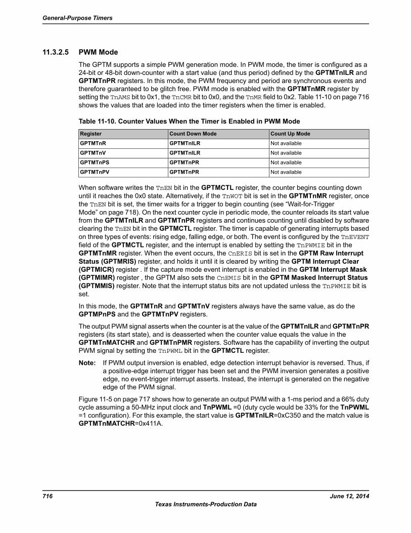
Figure 11-5 on page 717 shows how to generate an output PWMwith a 1-ms period and a 66% duty
cycle assuming a 50-MHz input clock and TnPWML =0 (duty cycle would be 33% for the TnPWML
=1 configuration). For this example, the start value is GPTMTnILR=0xC350 and the match value is
GPTMTnMATCHR=0x411A.
June 12, 2014716
Texas Instruments-Production Data
General-Purpose Timers
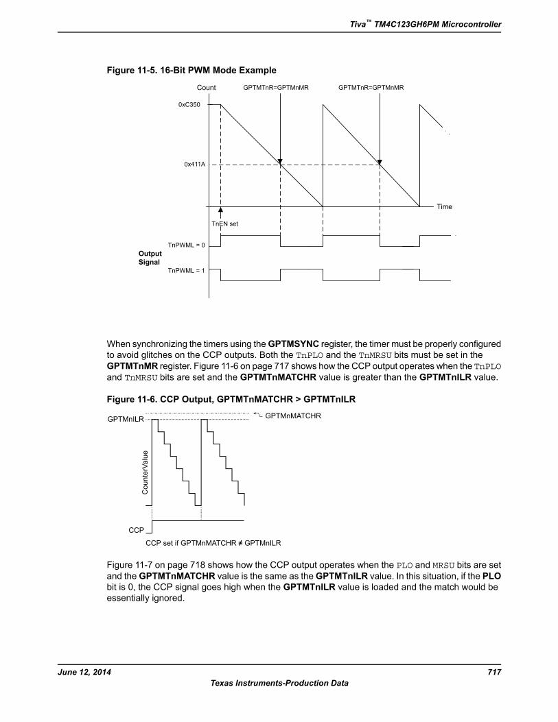
Figure 11-5. 16-Bit PWM Mode Example
Output
Signal
Time
Count GPTMTnR=GPTMnMR GPTMTnR=GPTMnMR
0xC350
0x411A
TnPWML = 0
TnPWML = 1
TnEN set
When synchronizing the timers using theGPTMSYNC register, the timer must be properly configured
to avoid glitches on the CCP outputs. Both the TnPLO and the TnMRSU bits must be set in theGPTMTnMR register. Figure 11-6 on page 717 shows how the CCP output operates when the TnPLOand TnMRSU bits are set and the GPTMTnMATCHR value is greater than the GPTMTnILR value.
Figure 11-6. CCP Output, GPTMTnMATCHR > GPTMTnILR
CCP
CounterValue
GPTMnMATCHRGPTMnILR
CCP set if GPTMnMATCHR ≠ GPTMnILR
Figure 11-7 on page 718 shows how the CCP output operates when the PLO and MRSU bits are setand theGPTMTnMATCHR value is the same as theGPTMTnILR value. In this situation, if the PLO
bit is 0, the CCP signal goes high when the GPTMTnILR value is loaded and the match would be
essentially ignored.
717June 12, 2014
Texas Instruments-Production Data
Tiva™ TM4C123GH6PM Microcontroller
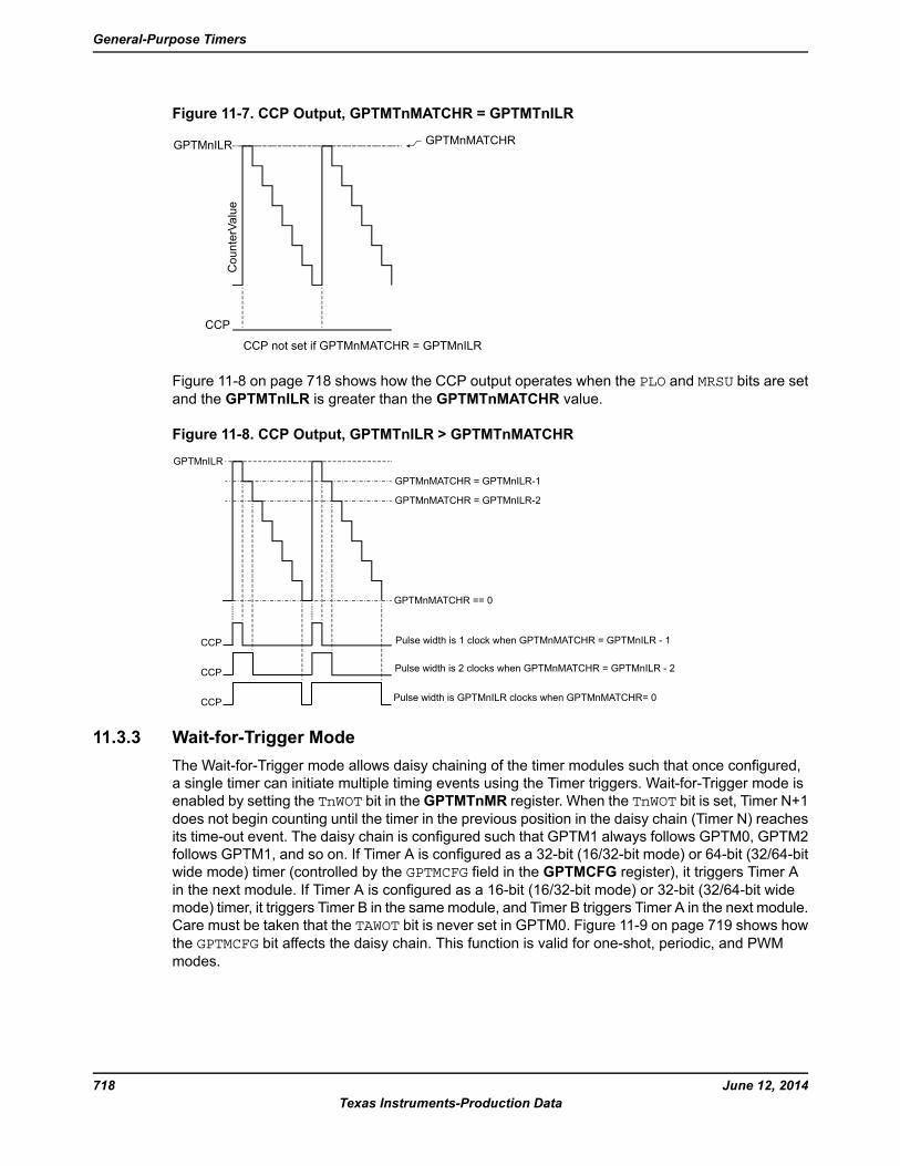
Figure 11-7. CCP Output, GPTMTnMATCHR = GPTMTnILR
CCP
CCP not set if GPTMnMATCHR = GPTMnILR
GPTMnMATCHR
CounterValue
GPTMnILR
Figure 11-8 on page 718 shows how the CCP output operates when the PLO and MRSU bits are setand the GPTMTnILR is greater than the GPTMTnMATCHR value.
Figure 11-8. CCP Output, GPTMTnILR > GPTMTnMATCHR
GPTMnMATCHR = GPTMnILR-1
GPTMnMATCHR = GPTMnILR-2
GPTMnILR
GPTMnMATCHR == 0
CCP
CCP
CCP
Pulse width is 1 clock when GPTMnMATCHR = GPTMnILR - 1
Pulse width is 2 clocks when GPTMnMATCHR = GPTMnILR - 2
Pulse width is GPTMnILR clocks when GPTMnMATCHR= 0
11.3.3 Wait-for-Trigger Mode
The Wait-for-Trigger mode allows daisy chaining of the timer modules such that once configured,
a single timer can initiate multiple timing events using the Timer triggers. Wait-for-Trigger mode is
enabled by setting the TnWOT bit in the GPTMTnMR register. When the TnWOT bit is set, Timer N+1does not begin counting until the timer in the previous position in the daisy chain (Timer N) reaches
its time-out event. The daisy chain is configured such that GPTM1 always follows GPTM0, GPTM2
follows GPTM1, and so on. If Timer A is configured as a 32-bit (16/32-bit mode) or 64-bit (32/64-bit
wide mode) timer (controlled by the GPTMCFG field in the GPTMCFG register), it triggers Timer A
in the next module. If Timer A is configured as a 16-bit (16/32-bit mode) or 32-bit (32/64-bit wide
mode) timer, it triggers Timer B in the samemodule, and Timer B triggers Timer A in the next module.
Care must be taken that the TAWOT bit is never set in GPTM0. Figure 11-9 on page 719 shows howthe GPTMCFG bit affects the daisy chain. This function is valid for one-shot, periodic, and PWMmodes.
June 12, 2014718
Texas Instruments-Production Data
General-Purpose Timers
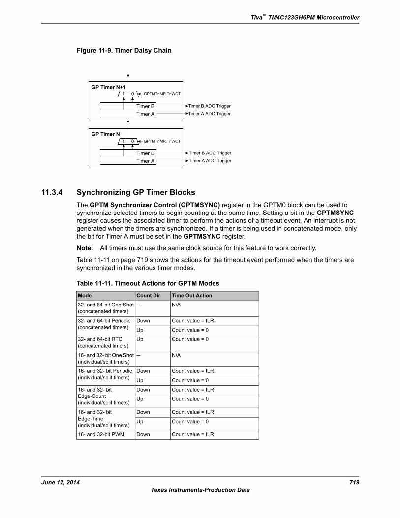
Figure 11-9. Timer Daisy Chain
GP Timer N
Timer B
Timer A
1 0
GP Timer N+1
Timer B
Timer A
1 0 GPTMTnMR.TnWOT
Timer B ADC Trigger
Timer A ADC Trigger
Timer B ADC Trigger
Timer A ADC Trigger
GPTMTnMR.TnWOT
11.3.4 Synchronizing GP Timer Blocks
The GPTM Synchronizer Control (GPTMSYNC) register in the GPTM0 block can be used to
synchronize selected timers to begin counting at the same time. Setting a bit in the GPTMSYNC
register causes the associated timer to perform the actions of a timeout event. An interrupt is not
generated when the timers are synchronized. If a timer is being used in concatenated mode, only
the bit for Timer A must be set in the GPTMSYNC register.
Note: All timers must use the same clock source for this feature to work correctly.
Table 11-11 on page 719 shows the actions for the timeout event performed when the timers are
synchronized in the various timer modes.
Table 11-11. Timeout Actions for GPTM Modes
Time Out ActionCount DirMode
N/A─32- and 64-bit One-Shot
(concatenated timers)
Count value = ILRDown32- and 64-bit Periodic
(concatenated timers)Count value = 0Up
Count value = 0Up32- and 64-bit RTC
(concatenated timers)
N/A─16- and 32- bit One Shot
(individual/split timers)
Count value = ILRDown16- and 32- bit Periodic
(individual/split timers)Count value = 0Up
Count value = ILRDown16- and 32- bit
Edge-Count
(individual/split timers)Count value = 0Up
Count value = ILRDown16- and 32- bit
Edge-Time
(individual/split timers)Count value = 0Up
Count value = ILRDown16- and 32-bit PWM
719June 12, 2014
Texas Instruments-Production Data
Tiva™ TM4C123GH6PM Microcontroller
11.3.5 DMA Operation
The timers each have a dedicated μDMA channel and can provide a request signal to the μDMA
controller. The request is a burst type and occurs whenever a timer raw interrupt condition occurs.
The arbitration size of the μDMA transfer should be set to the amount of data that should be
transferred whenever a timer event occurs.
For example, to transfer 256 items, 8 items at a time every 10 ms, configure a timer to generate a
periodic timeout at 10 ms. Configure the μDMA transfer for a total of 256 items, with a burst size of
8 items. Each time the timer times out, the μDMA controller transfers 8 items, until all 256 items
have been transferred.
No other special steps are needed to enable Timers for μDMA operation. Refer to “Micro Direct
Memory Access (μDMA)” on page 585 for more details about programming the μDMA controller.
11.3.6 Accessing Concatenated 16/32-Bit GPTM Register Values
The GPTM is placed into concatenated mode by writing a 0x0 or a 0x1 to the GPTMCFG bit field inthe GPTM Configuration (GPTMCFG) register. In both configurations, certain 16/32-bit GPTM
registers are concatenated to form pseudo 32-bit registers. These registers include:
■ GPTM Timer A Interval Load (GPTMTAILR) register [15:0], see page 756
■ GPTM Timer B Interval Load (GPTMTBILR) register [15:0], see page 757
■ GPTM Timer A (GPTMTAR) register [15:0], see page 764
■ GPTM Timer B (GPTMTBR) register [15:0], see page 765
■ GPTM Timer A Value (GPTMTAV) register [15:0], see page 766
■ GPTM Timer B Value (GPTMTBV) register [15:0], see page 767
■ GPTM Timer A Match (GPTMTAMATCHR) register [15:0], see page 758
■ GPTM Timer B Match (GPTMTBMATCHR) register [15:0], see page 759
In the 32-bit modes, the GPTM translates a 32-bit write access to GPTMTAILR into a write access
to both GPTMTAILR and GPTMTBILR. The resulting word ordering for such a write operation is:
GPTMTBILR[15:0]:GPTMTAILR[15:0]
Likewise, a 32-bit read access to GPTMTAR returns the value:
GPTMTBR[15:0]:GPTMTAR[15:0]
A 32-bit read access to GPTMTAV returns the value:
GPTMTBV[15:0]:GPTMTAV[15:0]
11.3.7 Accessing Concatenated 32/64-Bit Wide GPTM Register Values
On the 32/64-bit wide GPTM blocks, concatenated register values (64-bits and 48-bits) are not
readily available as the bit width for these accesses is greater than the bus width of the processor
core. In the concatenated timer modes and the individual timer modes when using the prescaler,
software must perform atomic accesses for the value to be coherent. When reading timer values
that are greater than 32 bits, software should follow these steps:
June 12, 2014720
Texas Instruments-Production Data
General-Purpose Timers
1. Read the appropriate Timer B register or prescaler register.
2. Read the corresponding Timer A register.
3. Re-read the Timer B register or prescaler register.
4. Compare the Timer B or prescaler values from the first and second reads. If they are the same,
the timer value is coherent. If they are not the same, repeat steps 1-4 once more so that they
are the same.
The following pseudo code illustrates this process:
high = timer_high;
low = timer_low;
if (high != timer_high); //low overflowed into high
{
high = timer_high;
low = timer_low;
}
The registers that must be read in this manner are shown below:
■ 64-bit reads
– GPTMTAV and GPTMTBV
– GPTMTAR and GPTMTBR
■ 48-bit reads
– GPTMTAR and GPTMTAPS
– GPTMTBR and GPTMTBPS
– GPTMTAV and GPTMTAPV
– GPTMTBV and GPTMTBPV
Similarly, write accesses must also be performed by writing the upper bits prior to writing the lower
bits as follows:
1. Write the appropriate Timer B register or prescaler register.
2. Write the corresponding Timer A register.
The registers that must be written in this manner are shown below:
■ 64-bit writes
– GPTMTAV and GPTMTBV
721June 12, 2014
Texas Instruments-Production Data
Tiva™ TM4C123GH6PM Microcontroller
– GPTMTAMATCHR and GPTMTBMATCHR
– GPTMTAILR and GPTMTBILR
■ 48-bit writes
– GPTMTAV and GPTMTAPV
– GPTMTBV and GPTMTBPV
– GPTMTAMATCHR and GPTMTAPMR
– GPTMTBMATCHR and GPTMTBPMR
– GPTMTAILR and GPTMTAPR
– GPTMTBILR and GPTMTBPR
When writing a 64-bit value, If there are two consecutive writes to any of the registers listed above
under the "64-bit writes" heading, whether the register is in Timer A or Timer B, or if a register Timer
A is written prior to writing the corresponding register in Timer B, then an error is reported using the
WUERIS bit in the GPTMRIS register. This error can be promoted to interrupt if it is not masked.
Note that this error is not reported for the prescaler registers because use of the prescaler is optional.
As a result, programmers must take care to follow the protocol outlined above.
11.4 Initialization and Configuration
To use a GPTM, the appropriate TIMERn bit must be set in the RCGCTIMER or RCGCWTIMER
register (see page 338 and page 357). If using any CCP pins, the clock to the appropriate GPIO
module must be enabled via the RCGCGPIO register (see page 340). To find out which GPIO port
to enable, refer to Table 23-4 on page 1344. Configure the PMCn fields in the GPIOPCTL register toassign the CCP signals to the appropriate pins (see page 688 and Table 23-5 on page 1351).
This section shows module initialization and configuration examples for each of the supported timer
modes.
11.4.1 One-Shot/Periodic Timer Mode
The GPTM is configured for One-Shot and Periodic modes by the following sequence:
1. Ensure the timer is disabled (the TnEN bit in the GPTMCTL register is cleared) before making
any changes.
2. Write the GPTM Configuration Register (GPTMCFG) with a value of 0x0000.0000.
3. Configure the TnMR field in the GPTM Timer n Mode Register (GPTMTnMR):
a. Write a value of 0x1 for One-Shot mode.
b. Write a value of 0x2 for Periodic mode.
4. Optionally configure the TnSNAPS, TnWOT, TnMTE, and TnCDIR bits in theGPTMTnMR register
to select whether to capture the value of the free-running timer at time-out, use an external
trigger to start counting, configure an additional trigger or interrupt, and count up or down.
5. Load the start value into the GPTM Timer n Interval Load Register (GPTMTnILR).
June 12, 2014722
Texas Instruments-Production Data
General-Purpose Timers
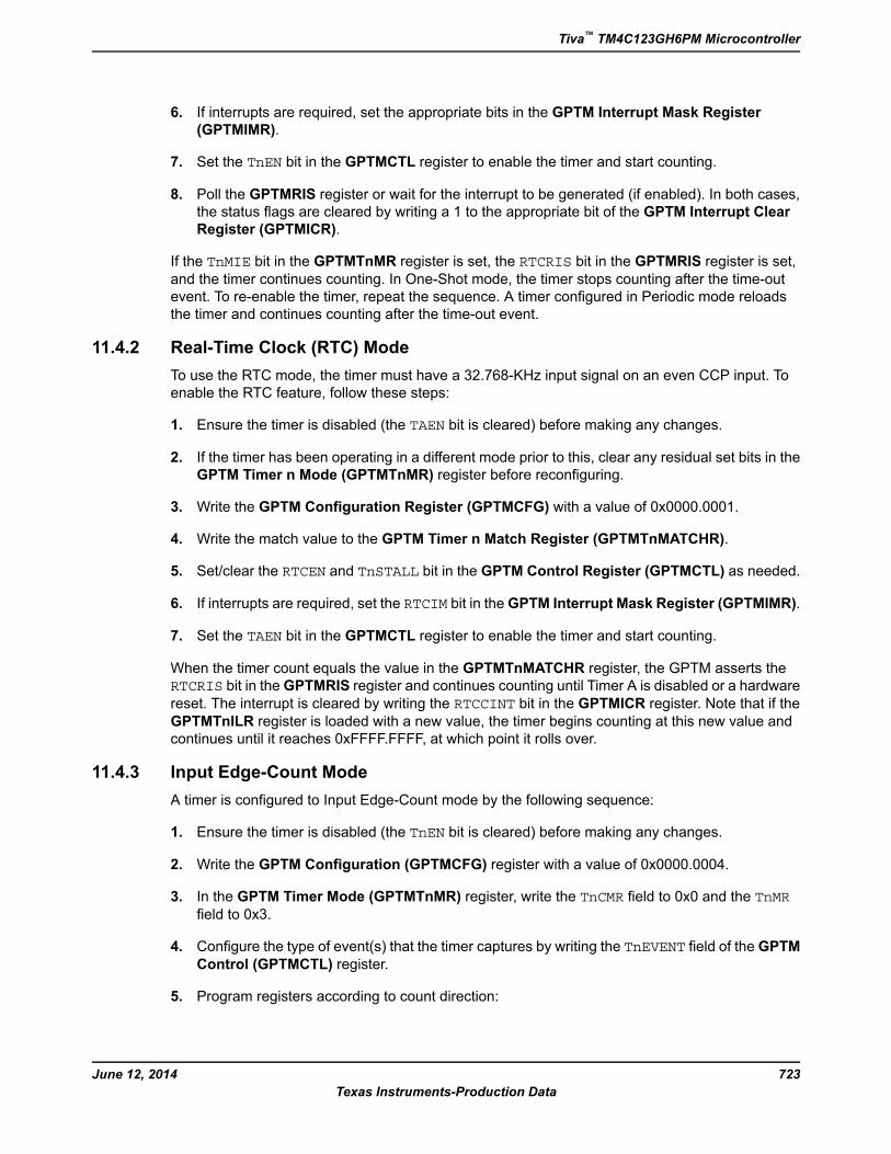
6. If interrupts are required, set the appropriate bits in the GPTM Interrupt Mask Register
(GPTMIMR).
7. Set the TnEN bit in the GPTMCTL register to enable the timer and start counting.
8. Poll the GPTMRIS register or wait for the interrupt to be generated (if enabled). In both cases,
the status flags are cleared by writing a 1 to the appropriate bit of the GPTM Interrupt Clear
Register (GPTMICR).
If the TnMIE bit in the GPTMTnMR register is set, the RTCRIS bit in the GPTMRIS register is set,
and the timer continues counting. In One-Shot mode, the timer stops counting after the time-out
event. To re-enable the timer, repeat the sequence. A timer configured in Periodic mode reloads
the timer and continues counting after the time-out event.
11.4.2 Real-Time Clock (RTC) Mode
To use the RTC mode, the timer must have a 32.768-KHz input signal on an even CCP input. To
enable the RTC feature, follow these steps:
1. Ensure the timer is disabled (the TAEN bit is cleared) before making any changes.
2. If the timer has been operating in a different mode prior to this, clear any residual set bits in the
GPTM Timer n Mode (GPTMTnMR) register before reconfiguring.
3. Write the GPTM Configuration Register (GPTMCFG) with a value of 0x0000.0001.
4. Write the match value to the GPTM Timer n Match Register (GPTMTnMATCHR).
5. Set/clear the RTCEN and TnSTALL bit in the GPTM Control Register (GPTMCTL) as needed.
6. If interrupts are required, set the RTCIM bit in theGPTM Interrupt Mask Register (GPTMIMR).
7. Set the TAEN bit in the GPTMCTL register to enable the timer and start counting.
When the timer count equals the value in the GPTMTnMATCHR register, the GPTM asserts the
RTCRIS bit in theGPTMRIS register and continues counting until Timer A is disabled or a hardware
reset. The interrupt is cleared by writing the RTCCINT bit in the GPTMICR register. Note that if the
GPTMTnILR register is loaded with a new value, the timer begins counting at this new value and
continues until it reaches 0xFFFF.FFFF, at which point it rolls over.
11.4.3 Input Edge-Count Mode
A timer is configured to Input Edge-Count mode by the following sequence:
1. Ensure the timer is disabled (the TnEN bit is cleared) before making any changes.
2. Write the GPTM Configuration (GPTMCFG) register with a value of 0x0000.0004.
3. In the GPTM Timer Mode (GPTMTnMR) register, write the TnCMR field to 0x0 and the TnMRfield to 0x3.
4. Configure the type of event(s) that the timer captures by writing the TnEVENT field of the GPTMControl (GPTMCTL) register.
5. Program registers according to count direction:
723June 12, 2014
Texas Instruments-Production Data
Tiva™ TM4C123GH6PM Microcontroller
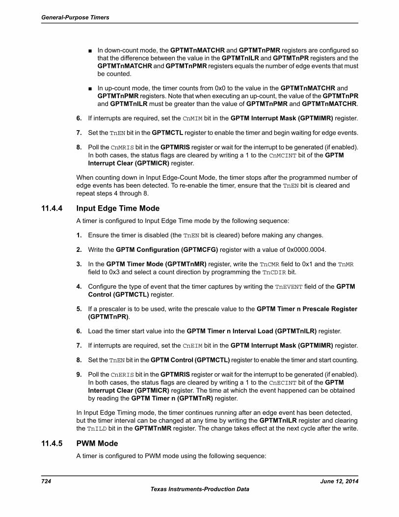
■ In down-count mode, the GPTMTnMATCHR and GPTMTnPMR registers are configured so
that the difference between the value in theGPTMTnILR and GPTMTnPR registers and the
GPTMTnMATCHR andGPTMTnPMR registers equals the number of edge events that must
be counted.
■ In up-count mode, the timer counts from 0x0 to the value in the GPTMTnMATCHR and
GPTMTnPMR registers. Note that when executing an up-count, the value of theGPTMTnPR
and GPTMTnILR must be greater than the value of GPTMTnPMR and GPTMTnMATCHR.
6. If interrupts are required, set the CnMIM bit in the GPTM Interrupt Mask (GPTMIMR) register.
7. Set the TnEN bit in theGPTMCTL register to enable the timer and begin waiting for edge events.
8. Poll the CnMRIS bit in theGPTMRIS register or wait for the interrupt to be generated (if enabled).
In both cases, the status flags are cleared by writing a 1 to the CnMCINT bit of the GPTMInterrupt Clear (GPTMICR) register.
When counting down in Input Edge-Count Mode, the timer stops after the programmed number of
edge events has been detected. To re-enable the timer, ensure that the TnEN bit is cleared andrepeat steps 4 through 8.
11.4.4 Input Edge Time Mode
A timer is configured to Input Edge Time mode by the following sequence:
1. Ensure the timer is disabled (the TnEN bit is cleared) before making any changes.
2. Write the GPTM Configuration (GPTMCFG) register with a value of 0x0000.0004.
3. In the GPTM Timer Mode (GPTMTnMR) register, write the TnCMR field to 0x1 and the TnMRfield to 0x3 and select a count direction by programming the TnCDIR bit.
4. Configure the type of event that the timer captures by writing the TnEVENT field of the GPTMControl (GPTMCTL) register.
5. If a prescaler is to be used, write the prescale value to the GPTM Timer n Prescale Register
(GPTMTnPR).
6. Load the timer start value into the GPTM Timer n Interval Load (GPTMTnILR) register.
7. If interrupts are required, set the CnEIM bit in the GPTM Interrupt Mask (GPTMIMR) register.
8. Set the TnEN bit in theGPTMControl (GPTMCTL) register to enable the timer and start counting.
9. Poll the CnERIS bit in theGPTMRIS register or wait for the interrupt to be generated (if enabled).
In both cases, the status flags are cleared by writing a 1 to the CnECINT bit of the GPTMInterrupt Clear (GPTMICR) register. The time at which the event happened can be obtained
by reading the GPTM Timer n (GPTMTnR) register.
In Input Edge Timing mode, the timer continues running after an edge event has been detected,
but the timer interval can be changed at any time by writing the GPTMTnILR register and clearing
the TnILD bit in the GPTMTnMR register. The change takes effect at the next cycle after the write.
11.4.5 PWM Mode
A timer is configured to PWM mode using the following sequence:
June 12, 2014724
Texas Instruments-Production Data
General-Purpose Timers
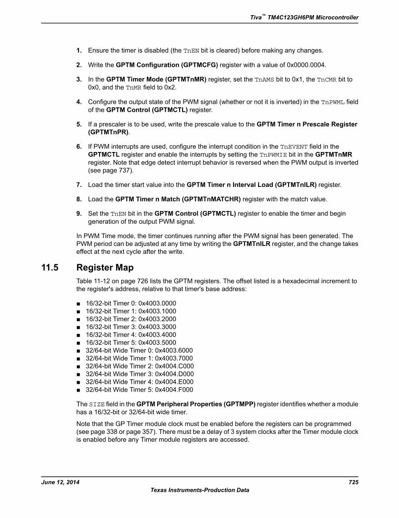
1. Ensure the timer is disabled (the TnEN bit is cleared) before making any changes.
2. Write the GPTM Configuration (GPTMCFG) register with a value of 0x0000.0004.
3. In the GPTM Timer Mode (GPTMTnMR) register, set the TnAMS bit to 0x1, the TnCMR bit to0x0, and the TnMR field to 0x2.
4. Configure the output state of the PWM signal (whether or not it is inverted) in the TnPWML fieldof the GPTM Control (GPTMCTL) register.
5. If a prescaler is to be used, write the prescale value to the GPTM Timer n Prescale Register
(GPTMTnPR).
6. If PWM interrupts are used, configure the interrupt condition in the TnEVENT field in theGPTMCTL register and enable the interrupts by setting the TnPWMIE bit in the GPTMTnMR
register. Note that edge detect interrupt behavior is reversed when the PWM output is inverted
(see page 737).
7. Load the timer start value into the GPTM Timer n Interval Load (GPTMTnILR) register.
8. Load the GPTM Timer n Match (GPTMTnMATCHR) register with the match value.
9. Set the TnEN bit in the GPTM Control (GPTMCTL) register to enable the timer and begin
generation of the output PWM signal.
In PWM Time mode, the timer continues running after the PWM signal has been generated. The
PWM period can be adjusted at any time by writing the GPTMTnILR register, and the change takes
effect at the next cycle after the write.
11.5 Register Map
Table 11-12 on page 726 lists the GPTM registers. The offset listed is a hexadecimal increment to
the register's address, relative to that timer's base address:
■ 16/32-bit Timer 0: 0x4003.0000
■ 16/32-bit Timer 1: 0x4003.1000
■ 16/32-bit Timer 2: 0x4003.2000
■ 16/32-bit Timer 3: 0x4003.3000
■ 16/32-bit Timer 4: 0x4003.4000
■ 16/32-bit Timer 5: 0x4003.5000
■ 32/64-bit Wide Timer 0: 0x4003.6000
■ 32/64-bit Wide Timer 1: 0x4003.7000
■ 32/64-bit Wide Timer 2: 0x4004.C000
■ 32/64-bit Wide Timer 3: 0x4004.D000
■ 32/64-bit Wide Timer 4: 0x4004.E000
■ 32/64-bit Wide Timer 5: 0x4004.F000
The SIZE field in theGPTM Peripheral Properties (GPTMPP) register identifies whether a module
has a 16/32-bit or 32/64-bit wide timer.
Note that the GP Timer module clock must be enabled before the registers can be programmed
(see page 338 or page 357). There must be a delay of 3 system clocks after the Timer module clock
is enabled before any Timer module registers are accessed.
725June 12, 2014
Texas Instruments-Production Data
Tiva™ TM4C123GH6PM Microcontroller
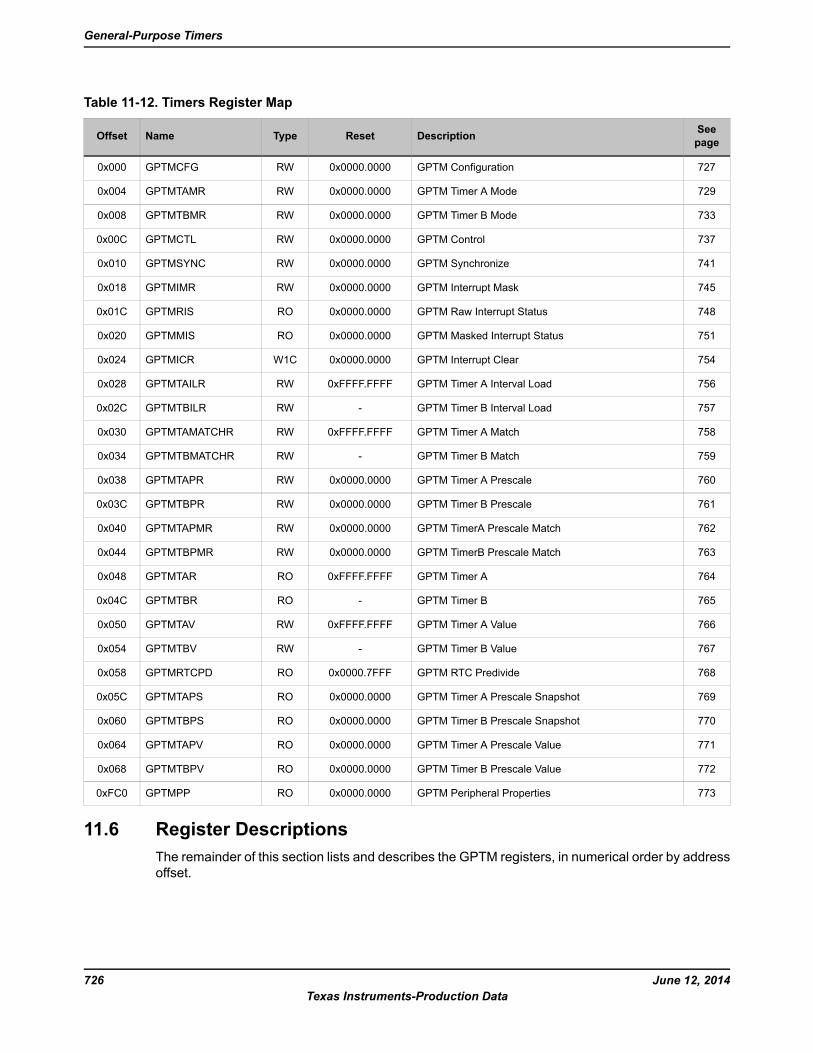
Table 11-12. Timers Register Map
See
pageDescriptionResetTypeNameOffset
727GPTM Configuration0x0000.0000RWGPTMCFG0x000
729GPTM Timer A Mode0x0000.0000RWGPTMTAMR0x004
733GPTM Timer B Mode0x0000.0000RWGPTMTBMR0x008
737GPTM Control0x0000.0000RWGPTMCTL0x00C
741GPTM Synchronize0x0000.0000RWGPTMSYNC0x010
745GPTM Interrupt Mask0x0000.0000RWGPTMIMR0x018
748GPTM Raw Interrupt Status0x0000.0000ROGPTMRIS0x01C
751GPTM Masked Interrupt Status0x0000.0000ROGPTMMIS0x020
754GPTM Interrupt Clear0x0000.0000W1CGPTMICR0x024
756GPTM Timer A Interval Load0xFFFF.FFFFRWGPTMTAILR0x028
757GPTM Timer B Interval Load-RWGPTMTBILR0x02C
758GPTM Timer A Match0xFFFF.FFFFRWGPTMTAMATCHR0x030
759GPTM Timer B Match-RWGPTMTBMATCHR0x034
760GPTM Timer A Prescale0x0000.0000RWGPTMTAPR0x038
761GPTM Timer B Prescale0x0000.0000RWGPTMTBPR0x03C
762GPTM TimerA Prescale Match0x0000.0000RWGPTMTAPMR0x040
763GPTM TimerB Prescale Match0x0000.0000RWGPTMTBPMR0x044
764GPTM Timer A0xFFFF.FFFFROGPTMTAR0x048
765GPTM Timer B-ROGPTMTBR0x04C
766GPTM Timer A Value0xFFFF.FFFFRWGPTMTAV0x050
767GPTM Timer B Value-RWGPTMTBV0x054
768GPTM RTC Predivide0x0000.7FFFROGPTMRTCPD0x058
769GPTM Timer A Prescale Snapshot0x0000.0000ROGPTMTAPS0x05C
770GPTM Timer B Prescale Snapshot0x0000.0000ROGPTMTBPS0x060
771GPTM Timer A Prescale Value0x0000.0000ROGPTMTAPV0x064
772GPTM Timer B Prescale Value0x0000.0000ROGPTMTBPV0x068
773GPTM Peripheral Properties0x0000.0000ROGPTMPP0xFC0
11.6 Register Descriptions
The remainder of this section lists and describes the GPTM registers, in numerical order by address
offset.
June 12, 2014726
Texas Instruments-Production Data
General-Purpose Timers
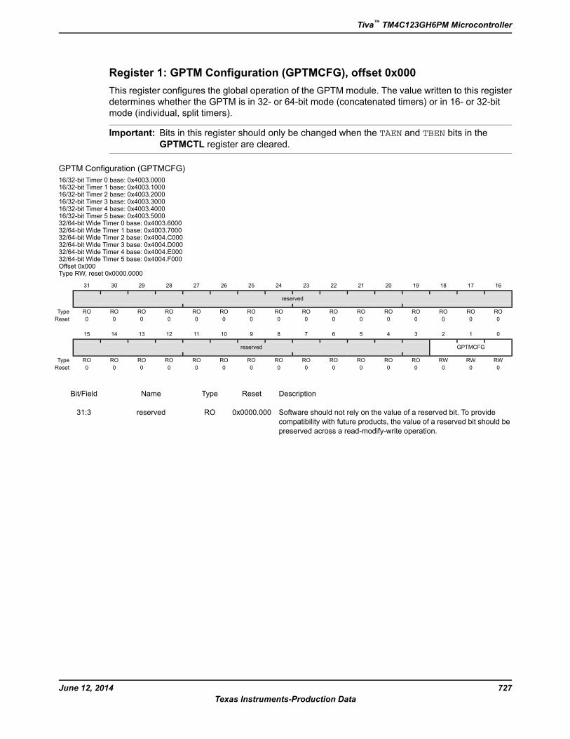
Register 1: GPTM Configuration (GPTMCFG), offset 0x000
This register configures the global operation of the GPTM module. The value written to this register
determines whether the GPTM is in 32- or 64-bit mode (concatenated timers) or in 16- or 32-bit
mode (individual, split timers).
Important: Bits in this register should only be changed when the TAEN and TBEN bits in theGPTMCTL register are cleared.
GPTM Configuration (GPTMCFG)
16/32-bit Timer 0 base: 0x4003.000016/32-bit Timer 1 base: 0x4003.100016/32-bit Timer 2 base: 0x4003.200016/32-bit Timer 3 base: 0x4003.300016/32-bit Timer 4 base: 0x4003.400016/32-bit Timer 5 base: 0x4003.500032/64-bit Wide Timer 0 base: 0x4003.600032/64-bit Wide Timer 1 base: 0x4003.700032/64-bit Wide Timer 2 base: 0x4004.C00032/64-bit Wide Timer 3 base: 0x4004.D00032/64-bit Wide Timer 4 base: 0x4004.E00032/64-bit Wide Timer 5 base: 0x4004.F000Offset 0x000Type RW, reset 0x0000.0000
16171819202122232425262728293031
reserved
ROROROROROROROROROROROROROROROROType
0000000000000000Reset
0123456789101112131415
GPTMCFGreserved
RWRWRWROROROROROROROROROROROROROType
0000000000000000Reset
DescriptionResetTypeNameBit/Field
Software should not rely on the value of a reserved bit. To provide
compatibility with future products, the value of a reserved bit should be
preserved across a read-modify-write operation.
0x0000.000ROreserved31:3
727June 12, 2014
Texas Instruments-Production Data
Tiva™ TM4C123GH6PM Microcontroller
DescriptionResetTypeNameBit/Field
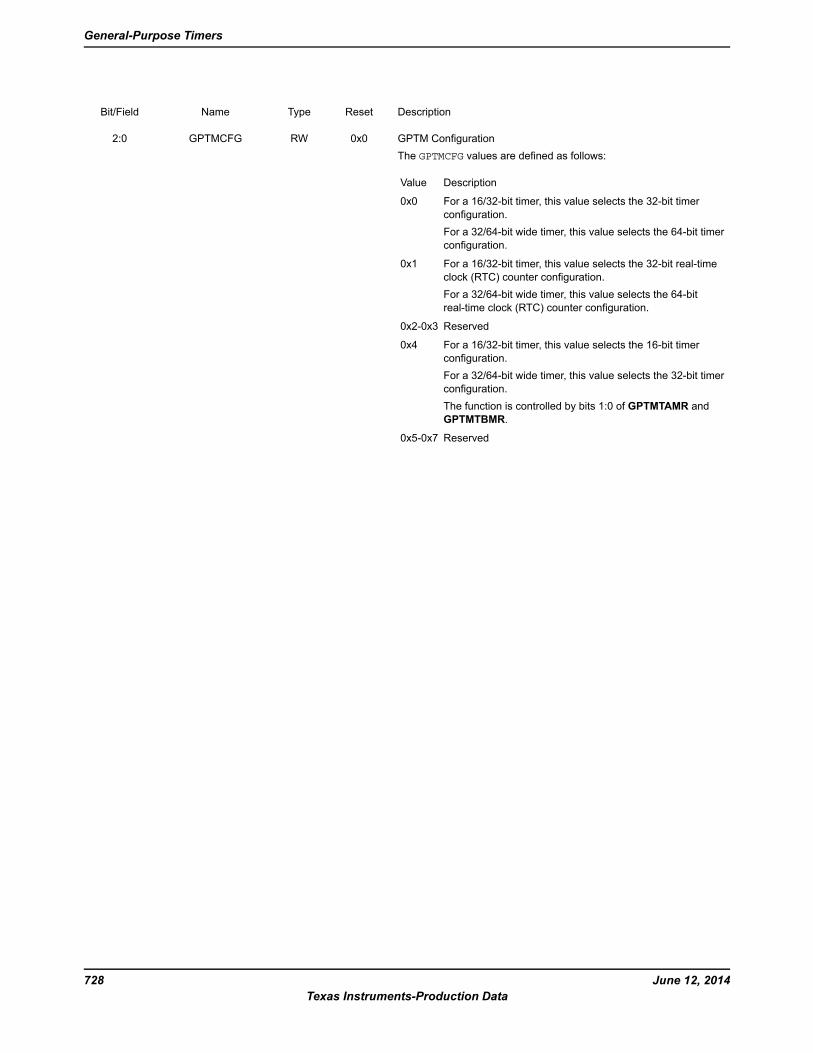
GPTM Configuration
The GPTMCFG values are defined as follows:
DescriptionValue
For a 16/32-bit timer, this value selects the 32-bit timer
configuration.
For a 32/64-bit wide timer, this value selects the 64-bit timer
configuration.
0x0
For a 16/32-bit timer, this value selects the 32-bit real-time
clock (RTC) counter configuration.
For a 32/64-bit wide timer, this value selects the 64-bit
real-time clock (RTC) counter configuration.
0x1
Reserved0x2-0x3
For a 16/32-bit timer, this value selects the 16-bit timer
configuration.
For a 32/64-bit wide timer, this value selects the 32-bit timer
configuration.
The function is controlled by bits 1:0 of GPTMTAMR and
GPTMTBMR.
0x4
Reserved0x5-0x7
0x0RWGPTMCFG2:0
June 12, 2014728
Texas Instruments-Production Data
General-Purpose Timers
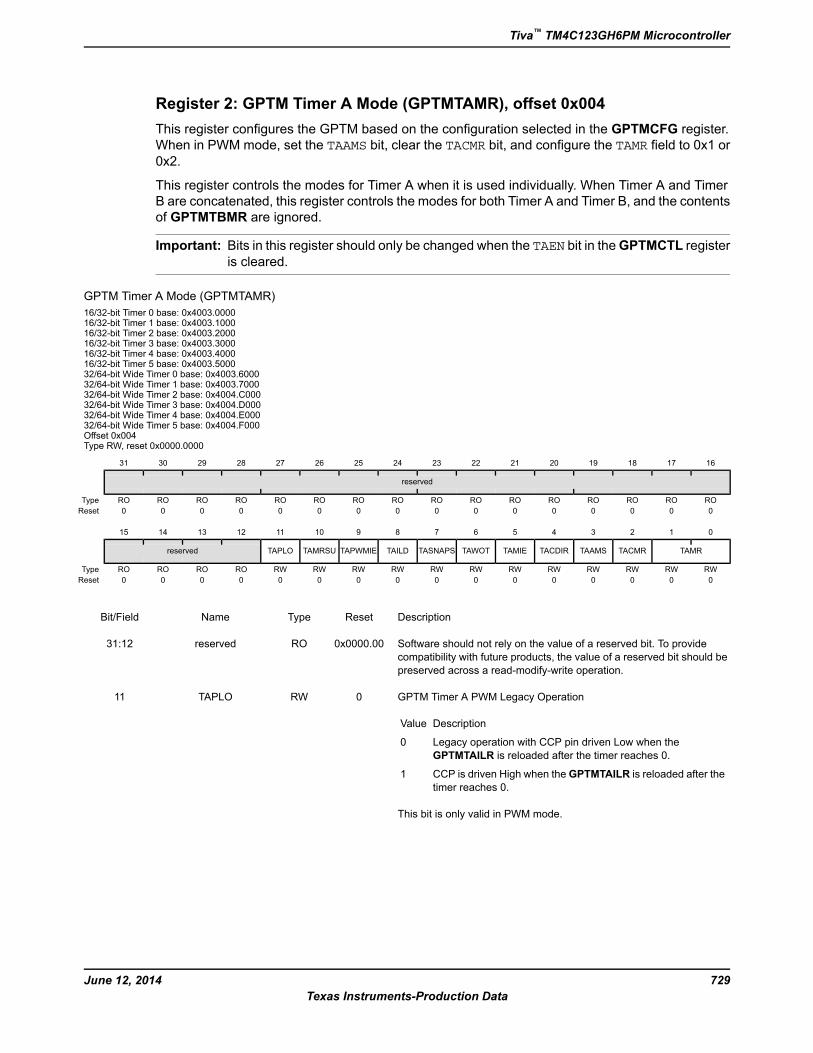
Register 2: GPTM Timer A Mode (GPTMTAMR), offset 0x004
This register configures the GPTM based on the configuration selected in the GPTMCFG register.
When in PWM mode, set the TAAMS bit, clear the TACMR bit, and configure the TAMR field to 0x1 or0x2.
This register controls the modes for Timer A when it is used individually. When Timer A and Timer
B are concatenated, this register controls the modes for both Timer A and Timer B, and the contents
of GPTMTBMR are ignored.
Important: Bits in this register should only be changed when the TAEN bit in theGPTMCTL register
is cleared.
GPTM Timer A Mode (GPTMTAMR)
16/32-bit Timer 0 base: 0x4003.000016/32-bit Timer 1 base: 0x4003.100016/32-bit Timer 2 base: 0x4003.200016/32-bit Timer 3 base: 0x4003.300016/32-bit Timer 4 base: 0x4003.400016/32-bit Timer 5 base: 0x4003.500032/64-bit Wide Timer 0 base: 0x4003.600032/64-bit Wide Timer 1 base: 0x4003.700032/64-bit Wide Timer 2 base: 0x4004.C00032/64-bit Wide Timer 3 base: 0x4004.D00032/64-bit Wide Timer 4 base: 0x4004.E00032/64-bit Wide Timer 5 base: 0x4004.F000Offset 0x004Type RW, reset 0x0000.0000
16171819202122232425262728293031
reserved
ROROROROROROROROROROROROROROROROType
0000000000000000Reset
0123456789101112131415
TAMRTACMRTAAMSTACDIRTAMIETAWOTTASNAPSTAILDTAPWMIETAMRSUTAPLOreserved
RWRWRWRWRWRWRWRWRWRWRWRWROROROROType
0000000000000000Reset
DescriptionResetTypeNameBit/Field
Software should not rely on the value of a reserved bit. To provide
compatibility with future products, the value of a reserved bit should be
preserved across a read-modify-write operation.
0x0000.00ROreserved31:12
GPTM Timer A PWM Legacy Operation
DescriptionValue
Legacy operation with CCP pin driven Low when the
GPTMTAILR is reloaded after the timer reaches 0.
0
CCP is driven High when theGPTMTAILR is reloaded after the
timer reaches 0.
1
This bit is only valid in PWM mode.
0RWTAPLO11
729June 12, 2014
Texas Instruments-Production Data
Tiva™ TM4C123GH6PM Microcontroller
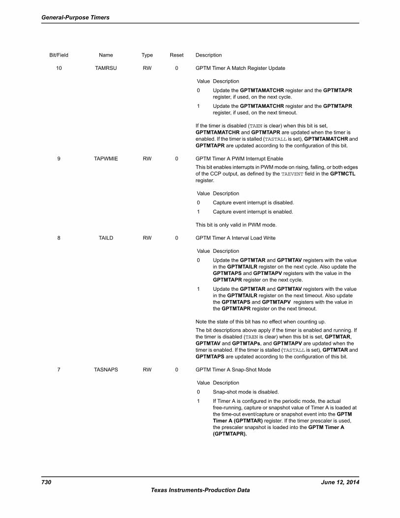
DescriptionResetTypeNameBit/Field
GPTM Timer A Match Register Update
DescriptionValue
Update the GPTMTAMATCHR register and the GPTMTAPR
register, if used, on the next cycle.
0
Update the GPTMTAMATCHR register and the GPTMTAPR
register, if used, on the next timeout.
1
If the timer is disabled (TAEN is clear) when this bit is set,
GPTMTAMATCHR and GPTMTAPR are updated when the timer is
enabled. If the timer is stalled (TASTALL is set),GPTMTAMATCHR and
GPTMTAPR are updated according to the configuration of this bit.
0RWTAMRSU10
GPTM Timer A PWM Interrupt Enable
This bit enables interrupts in PWMmode on rising, falling, or both edges
of the CCP output, as defined by the TAEVENT field in the GPTMCTL
register.
DescriptionValue
Capture event interrupt is disabled.0
Capture event interrupt is enabled.1
This bit is only valid in PWM mode.
0RWTAPWMIE9
GPTM Timer A Interval Load Write
DescriptionValue
Update the GPTMTAR and GPTMTAV registers with the value
in the GPTMTAILR register on the next cycle. Also update the
GPTMTAPS and GPTMTAPV registers with the value in the
GPTMTAPR register on the next cycle.
0
Update the GPTMTAR and GPTMTAV registers with the value
in the GPTMTAILR register on the next timeout. Also update
the GPTMTAPS and GPTMTAPV registers with the value in
the GPTMTAPR register on the next timeout.
1
Note the state of this bit has no effect when counting up.
The bit descriptions above apply if the timer is enabled and running. If
the timer is disabled (TAEN is clear) when this bit is set, GPTMTAR,
GPTMTAV and GPTMTAPs, and GPTMTAPV are updated when the
timer is enabled. If the timer is stalled (TASTALL is set),GPTMTAR and
GPTMTAPS are updated according to the configuration of this bit.
0RWTAILD8
GPTM Timer A Snap-Shot Mode
DescriptionValue
Snap-shot mode is disabled.0
If Timer A is configured in the periodic mode, the actual
free-running, capture or snapshot value of Timer A is loaded at
the time-out event/capture or snapshot event into the GPTM
Timer A (GPTMTAR) register. If the timer prescaler is used,
the prescaler snapshot is loaded into the GPTM Timer A
(GPTMTAPR).
1
0RWTASNAPS7
June 12, 2014730
Texas Instruments-Production Data
General-Purpose Timers
DescriptionResetTypeNameBit/Field
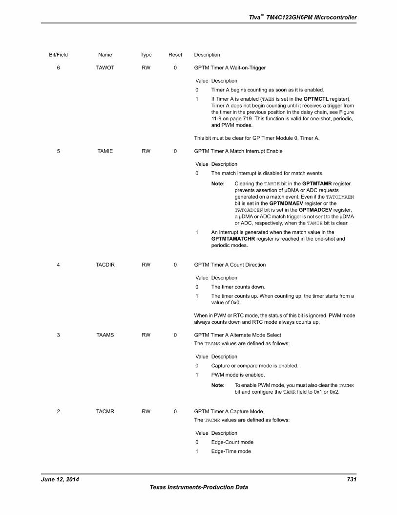
GPTM Timer A Wait-on-Trigger
DescriptionValue
Timer A begins counting as soon as it is enabled.0
If Timer A is enabled (TAEN is set in the GPTMCTL register),
Timer A does not begin counting until it receives a trigger from
the timer in the previous position in the daisy chain, see Figure
11-9 on page 719. This function is valid for one-shot, periodic,
and PWM modes.
1
This bit must be clear for GP Timer Module 0, Timer A.
0RWTAWOT6
GPTM Timer A Match Interrupt Enable
DescriptionValue
The match interrupt is disabled for match events.0
Note: Clearing the TAMIE bit in the GPTMTAMR register
prevents assertion of µDMA or ADC requests
generated on a match event. Even if the TATODMAEN
bit is set in the GPTMDMAEV register or the
TATOADCEN bit is set in the GPTMADCEV register,
a µDMA or ADCmatch trigger is not sent to the µDMA
or ADC, respectively, when the TAMIE bit is clear.
An interrupt is generated when the match value in the
GPTMTAMATCHR register is reached in the one-shot and
periodic modes.
1
0RWTAMIE5
GPTM Timer A Count Direction
DescriptionValue
The timer counts down.0
The timer counts up. When counting up, the timer starts from a
value of 0x0.
1
When in PWM or RTCmode, the status of this bit is ignored. PWMmode
always counts down and RTC mode always counts up.
0RWTACDIR4
GPTM Timer A Alternate Mode Select
The TAAMS values are defined as follows:
DescriptionValue
Capture or compare mode is enabled.0
PWM mode is enabled.1
Note: To enable PWMmode, youmust also clear the TACMR
bit and configure the TAMR field to 0x1 or 0x2.
0RWTAAMS3
GPTM Timer A Capture Mode
The TACMR values are defined as follows:
DescriptionValue
Edge-Count mode0
Edge-Time mode1
0RWTACMR2
731June 12, 2014
Texas Instruments-Production Data
Tiva™ TM4C123GH6PM Microcontroller

DescriptionResetTypeNameBit/Field
GPTM Timer A Mode
The TAMR values are defined as follows:
DescriptionValue
Reserved0x0
One-Shot Timer mode0x1
Periodic Timer mode0x2
Capture mode0x3
The Timer mode is based on the timer configuration defined by bits 2:0
in the GPTMCFG register.
0x0RWTAMR1:0
June 12, 2014732
Texas Instruments-Production Data
General-Purpose Timers
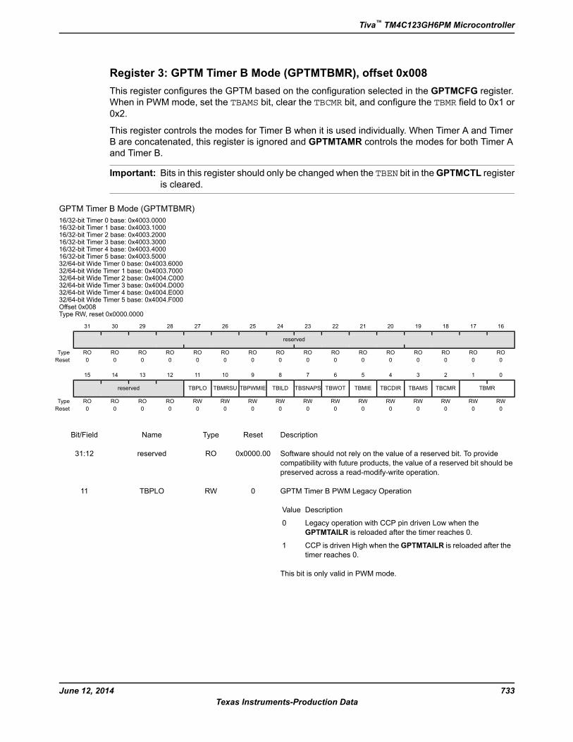
Register 3: GPTM Timer B Mode (GPTMTBMR), offset 0x008
This register configures the GPTM based on the configuration selected in the GPTMCFG register.
When in PWM mode, set the TBAMS bit, clear the TBCMR bit, and configure the TBMR field to 0x1 or0x2.
This register controls the modes for Timer B when it is used individually. When Timer A and Timer
B are concatenated, this register is ignored and GPTMTAMR controls the modes for both Timer A
and Timer B.
Important: Bits in this register should only be changed when the TBEN bit in theGPTMCTL register
is cleared.
GPTM Timer B Mode (GPTMTBMR)
16/32-bit Timer 0 base: 0x4003.000016/32-bit Timer 1 base: 0x4003.100016/32-bit Timer 2 base: 0x4003.200016/32-bit Timer 3 base: 0x4003.300016/32-bit Timer 4 base: 0x4003.400016/32-bit Timer 5 base: 0x4003.500032/64-bit Wide Timer 0 base: 0x4003.600032/64-bit Wide Timer 1 base: 0x4003.700032/64-bit Wide Timer 2 base: 0x4004.C00032/64-bit Wide Timer 3 base: 0x4004.D00032/64-bit Wide Timer 4 base: 0x4004.E00032/64-bit Wide Timer 5 base: 0x4004.F000Offset 0x008Type RW, reset 0x0000.0000
16171819202122232425262728293031
reserved
ROROROROROROROROROROROROROROROROType
0000000000000000Reset
0123456789101112131415
TBMRTBCMRTBAMSTBCDIRTBMIETBWOTTBSNAPSTBILDTBPWMIETBMRSUTBPLOreserved
RWRWRWRWRWRWRWRWRWRWRWRWROROROROType
0000000000000000Reset
DescriptionResetTypeNameBit/Field
Software should not rely on the value of a reserved bit. To provide
compatibility with future products, the value of a reserved bit should be
preserved across a read-modify-write operation.
0x0000.00ROreserved31:12
GPTM Timer B PWM Legacy Operation
DescriptionValue
Legacy operation with CCP pin driven Low when the
GPTMTAILR is reloaded after the timer reaches 0.
0
CCP is driven High when theGPTMTAILR is reloaded after the
timer reaches 0.
1
This bit is only valid in PWM mode.
0RWTBPLO11
733June 12, 2014
Texas Instruments-Production Data
Tiva™ TM4C123GH6PM Microcontroller
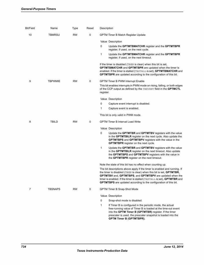
DescriptionResetTypeNameBit/Field
GPTM Timer B Match Register Update
DescriptionValue
Update the GPTMTBMATCHR register and the GPTMTBPR
register, if used, on the next cycle.
0
Update the GPTMTBMATCHR register and the GPTMTBPR
register, if used, on the next timeout.
1
If the timer is disabled (TBEN is clear) when this bit is set,
GPTMTBMATCHR and GPTMTBPR are updated when the timer is
enabled. If the timer is stalled (TBSTALL is set),GPTMTBMATCHR and
GPTMTBPR are updated according to the configuration of this bit.
0RWTBMRSU10
GPTM Timer B PWM Interrupt Enable
This bit enables interrupts in PWMmode on rising, falling, or both edges
of the CCP output as defined by the TBEVENT field in the GPTMCTL
register.
DescriptionValue
Capture event interrupt is disabled.0
Capture event is enabled.1
This bit is only valid in PWM mode.
0RWTBPWMIE9
GPTM Timer B Interval Load Write
DescriptionValue
Update the GPTMTBR and GPTMTBV registers with the value
in the GPTMTBILR register on the next cycle. Also update the
GPTMTBPS and GPTMTBPV registers with the value in the
GPTMTBPR register on the next cycle.
0
Update the GPTMTBR and GPTMTBV registers with the value
in the GPTMTBILR register on the next timeout. Also update
the GPTMTBPS and GPTMTBPV registers with the value in
the GPTMTBPR register on the next timeout.
1
Note the state of this bit has no effect when counting up.
The bit descriptions above apply if the timer is enabled and running. If
the timer is disabled (TBEN is clear) when this bit is set, GPTMTBR,
GPTMTBV and, GPTMTBPS, and GPTMTBPV are updated when the
timer is enabled. If the timer is stalled (TBSTALL is set),GPTMTBR and
GPTMTBPS are updated according to the configuration of this bit.
0RWTBILD8
GPTM Timer B Snap-Shot Mode
DescriptionValue
Snap-shot mode is disabled.0
If Timer B is configured in the periodic mode, the actual
free-running value of Timer B is loaded at the time-out event
into the GPTM Timer B (GPTMTBR) register. If the timer
prescaler is used, the prescaler snapshot is loaded into the
GPTM Timer B (GPTMTBPR).
1
0RWTBSNAPS7
June 12, 2014734
Texas Instruments-Production Data
General-Purpose Timers

DescriptionResetTypeNameBit/Field
GPTM Timer B Wait-on-Trigger
DescriptionValue
Timer B begins counting as soon as it is enabled.0
If Timer B is enabled (TBEN is set in the GPTMCTL register),
Timer B does not begin counting until it receives a trigger from
the timer in the previous position in the daisy chain, see Figure
11-9 on page 719. This function is valid for one-shot, periodic,
and PWM modes.
1
0RWTBWOT6
GPTM Timer B Match Interrupt Enable
DescriptionValue
The match interrupt is disabled for match events.0
An interrupt is generated when the match value in the
GPTMTBMATCHR register is reached in the one-shot and
periodic modes.
1
Note: Clearing the TBMIE bit in the GPTMTBMR register
prevents assertion of µDMA or ADC requests
generated on a match event. Even if the TBTODMAEN
bit is set in the GPTMDMAEV register or the
TBTOADCEN bit is set in the GPTMADCEV register,
a µDMA or ADCmatch trigger is not sent to the µDMA
or ADC, respectively, when the TBMIE bit is clear.
0RWTBMIE5
GPTM Timer B Count Direction
DescriptionValue
The timer counts down.0
The timer counts up. When counting up, the timer starts from a
value of 0x0.
1
When in PWM or RTCmode, the status of this bit is ignored. PWMmode
always counts down and RTC mode always counts up.
0RWTBCDIR4
GPTM Timer B Alternate Mode Select
The TBAMS values are defined as follows:
DescriptionValue
Capture or compare mode is enabled.0
PWM mode is enabled.1
Note: To enable PWMmode, youmust also clear the TBCMR
bit and configure the TBMR field to 0x1 or 0x2.
0RWTBAMS3
GPTM Timer B Capture Mode
The TBCMR values are defined as follows:
DescriptionValue
Edge-Count mode0
Edge-Time mode1
0RWTBCMR2
735June 12, 2014
Texas Instruments-Production Data
Tiva™ TM4C123GH6PM Microcontroller
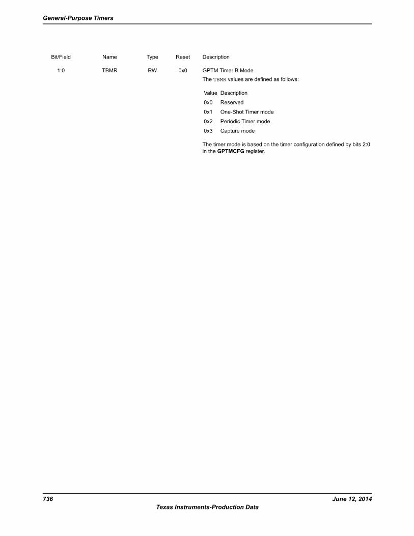
DescriptionResetTypeNameBit/Field
GPTM Timer B Mode
The TBMR values are defined as follows:
DescriptionValue
Reserved0x0
One-Shot Timer mode0x1
Periodic Timer mode0x2
Capture mode0x3
The timer mode is based on the timer configuration defined by bits 2:0
in the GPTMCFG register.
0x0RWTBMR1:0
June 12, 2014736
Texas Instruments-Production Data
General-Purpose Timers
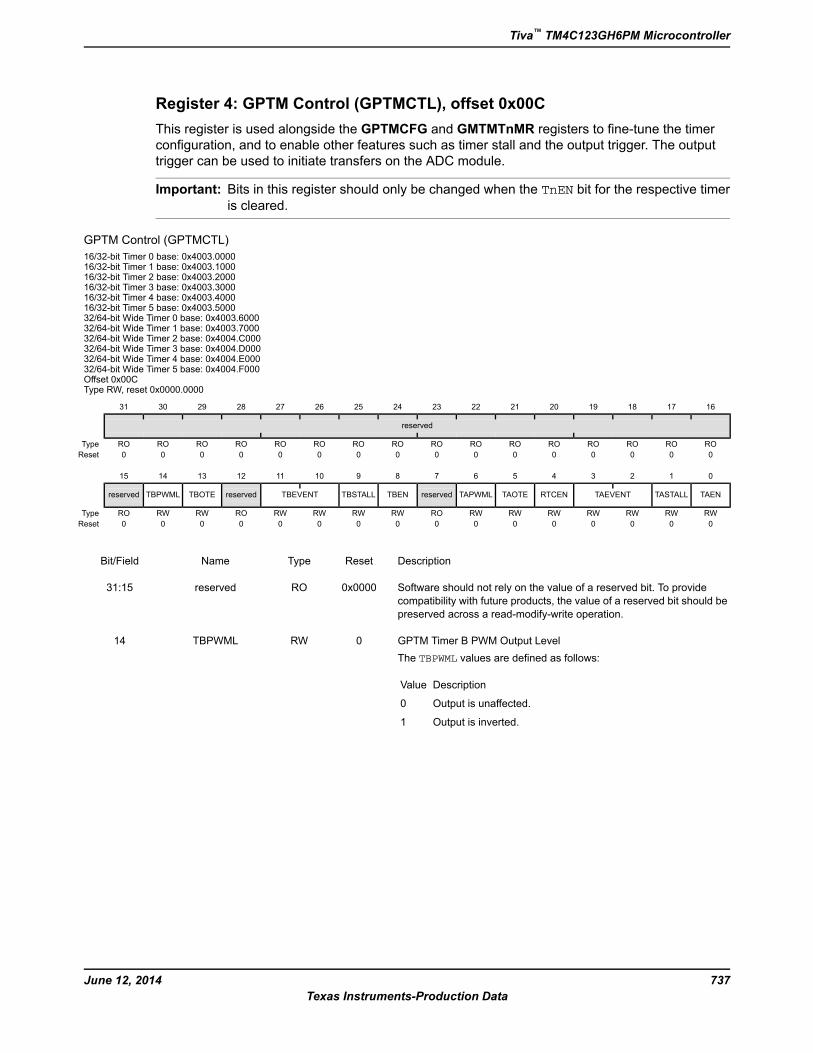
Register 4: GPTM Control (GPTMCTL), offset 0x00C
This register is used alongside the GPTMCFG and GMTMTnMR registers to fine-tune the timer
configuration, and to enable other features such as timer stall and the output trigger. The output
trigger can be used to initiate transfers on the ADC module.
Important: Bits in this register should only be changed when the TnEN bit for the respective timeris cleared.
GPTM Control (GPTMCTL)
16/32-bit Timer 0 base: 0x4003.000016/32-bit Timer 1 base: 0x4003.100016/32-bit Timer 2 base: 0x4003.200016/32-bit Timer 3 base: 0x4003.300016/32-bit Timer 4 base: 0x4003.400016/32-bit Timer 5 base: 0x4003.500032/64-bit Wide Timer 0 base: 0x4003.600032/64-bit Wide Timer 1 base: 0x4003.700032/64-bit Wide Timer 2 base: 0x4004.C00032/64-bit Wide Timer 3 base: 0x4004.D00032/64-bit Wide Timer 4 base: 0x4004.E00032/64-bit Wide Timer 5 base: 0x4004.F000Offset 0x00CType RW, reset 0x0000.0000
16171819202122232425262728293031
reserved
ROROROROROROROROROROROROROROROROType
0000000000000000Reset
0123456789101112131415
TAENTASTALLTAEVENTRTCENTAOTETAPWMLreservedTBENTBSTALLTBEVENTreservedTBOTETBPWMLreserved
RWRWRWRWRWRWRWRORWRWRWRWRORWRWROType
0000000000000000Reset
DescriptionResetTypeNameBit/Field
Software should not rely on the value of a reserved bit. To provide
compatibility with future products, the value of a reserved bit should be
preserved across a read-modify-write operation.
0x0000ROreserved31:15
GPTM Timer B PWM Output Level
The TBPWML values are defined as follows:
DescriptionValue
Output is unaffected.0
Output is inverted.1
0RWTBPWML14
737June 12, 2014
Texas Instruments-Production Data
Tiva™ TM4C123GH6PM Microcontroller
DescriptionResetTypeNameBit/Field
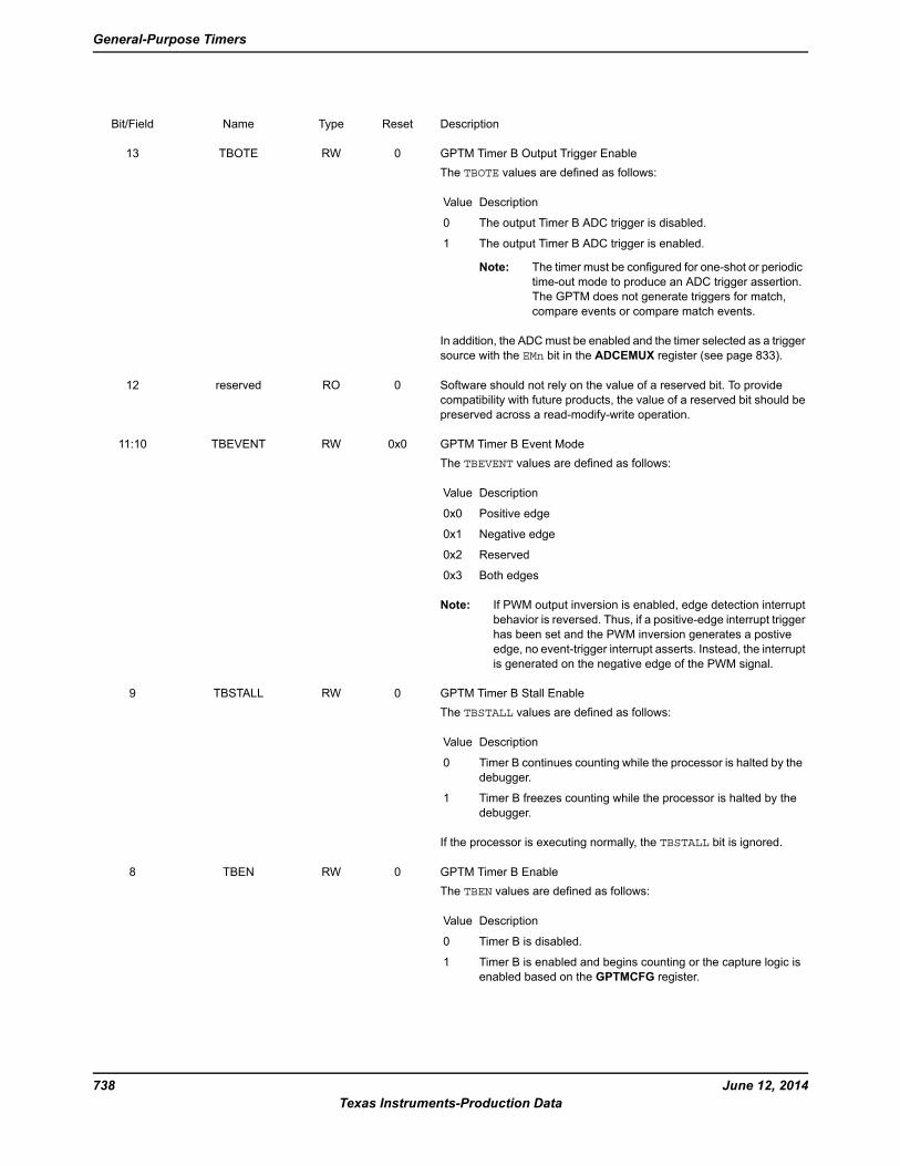
GPTM Timer B Output Trigger Enable
The TBOTE values are defined as follows:
DescriptionValue
The output Timer B ADC trigger is disabled.0
The output Timer B ADC trigger is enabled.1
Note: The timer must be configured for one-shot or periodic
time-out mode to produce an ADC trigger assertion.
The GPTM does not generate triggers for match,
compare events or compare match events.
In addition, the ADCmust be enabled and the timer selected as a trigger
source with the EMn bit in the ADCEMUX register (see page 833).
0RWTBOTE13
Software should not rely on the value of a reserved bit. To provide
compatibility with future products, the value of a reserved bit should be
preserved across a read-modify-write operation.
0ROreserved12
GPTM Timer B Event Mode
The TBEVENT values are defined as follows:
DescriptionValue
Positive edge0x0
Negative edge0x1
Reserved0x2
Both edges0x3
Note: If PWM output inversion is enabled, edge detection interrupt
behavior is reversed. Thus, if a positive-edge interrupt trigger
has been set and the PWM inversion generates a postive
edge, no event-trigger interrupt asserts. Instead, the interrupt
is generated on the negative edge of the PWM signal.
0x0RWTBEVENT11:10
GPTM Timer B Stall Enable
The TBSTALL values are defined as follows:
DescriptionValue
Timer B continues counting while the processor is halted by the
debugger.
0
Timer B freezes counting while the processor is halted by the
debugger.
1
If the processor is executing normally, the TBSTALL bit is ignored.
0RWTBSTALL9
GPTM Timer B Enable
The TBEN values are defined as follows:
DescriptionValue
Timer B is disabled.0
Timer B is enabled and begins counting or the capture logic is
enabled based on the GPTMCFG register.
1
0RWTBEN8
June 12, 2014738
Texas Instruments-Production Data
General-Purpose Timers
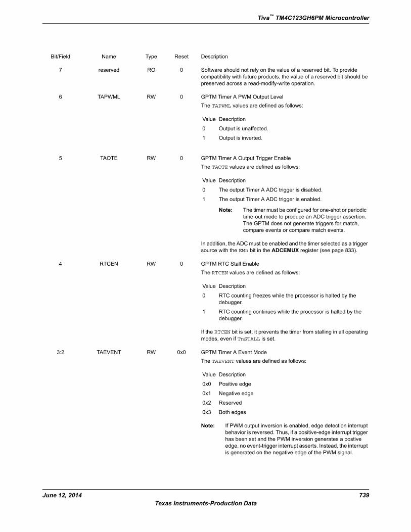
DescriptionResetTypeNameBit/Field
Software should not rely on the value of a reserved bit. To provide
compatibility with future products, the value of a reserved bit should be
preserved across a read-modify-write operation.
0ROreserved7
GPTM Timer A PWM Output Level
The TAPWML values are defined as follows:
DescriptionValue
Output is unaffected.0
Output is inverted.1
0RWTAPWML6
GPTM Timer A Output Trigger Enable
The TAOTE values are defined as follows:
DescriptionValue
The output Timer A ADC trigger is disabled.0
The output Timer A ADC trigger is enabled.1
Note: The timer must be configured for one-shot or periodic
time-out mode to produce an ADC trigger assertion.
The GPTM does not generate triggers for match,
compare events or compare match events.
In addition, the ADCmust be enabled and the timer selected as a trigger
source with the EMn bit in the ADCEMUX register (see page 833).
0RWTAOTE5
GPTM RTC Stall Enable
The RTCEN values are defined as follows:
DescriptionValue
RTC counting freezes while the processor is halted by the
debugger.
0
RTC counting continues while the processor is halted by the
debugger.
1
If the RTCEN bit is set, it prevents the timer from stalling in all operating
modes, even if TnSTALL is set.
0RWRTCEN4
GPTM Timer A Event Mode
The TAEVENT values are defined as follows:
DescriptionValue
Positive edge0x0
Negative edge0x1
Reserved0x2
Both edges0x3
Note: If PWM output inversion is enabled, edge detection interrupt
behavior is reversed. Thus, if a positive-edge interrupt trigger
has been set and the PWM inversion generates a postive
edge, no event-trigger interrupt asserts. Instead, the interrupt
is generated on the negative edge of the PWM signal.
0x0RWTAEVENT3:2
739June 12, 2014
Texas Instruments-Production Data
Tiva™ TM4C123GH6PM Microcontroller
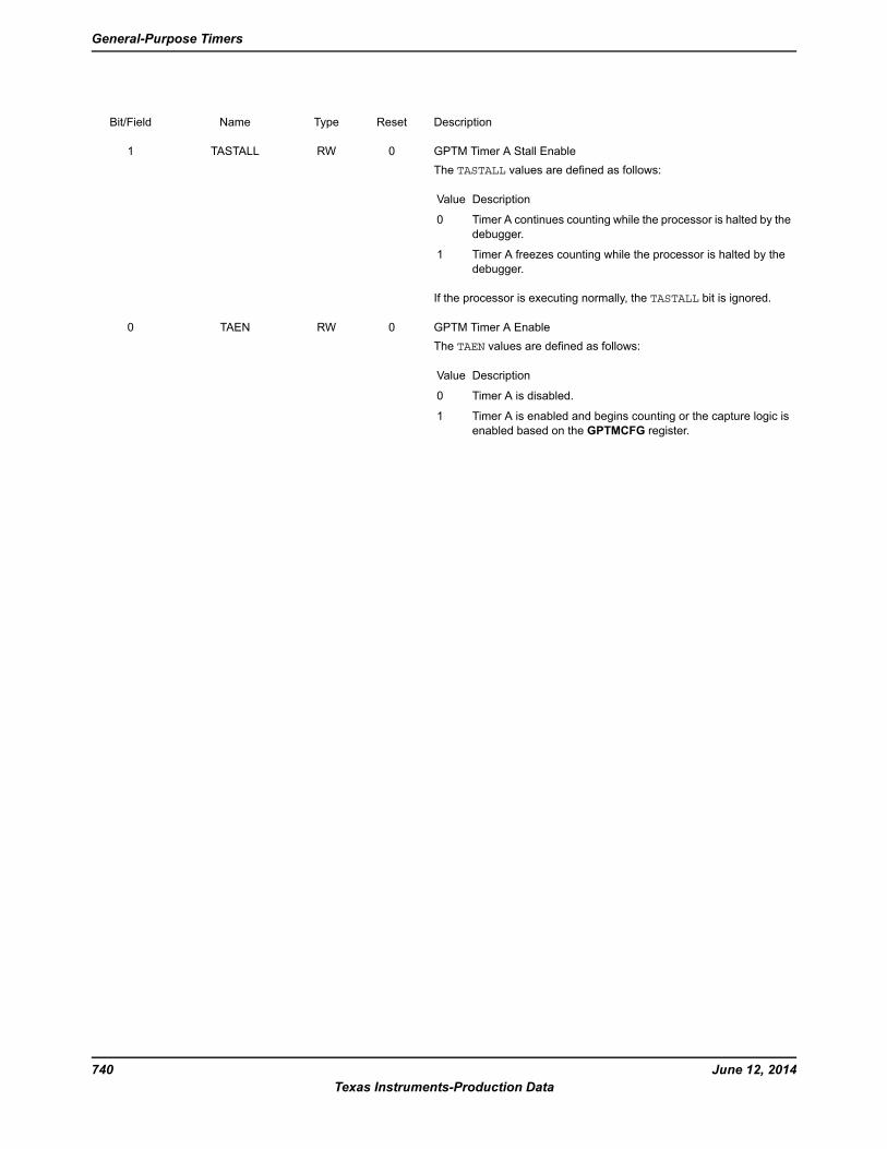
DescriptionResetTypeNameBit/Field
GPTM Timer A Stall Enable
The TASTALL values are defined as follows:
DescriptionValue
Timer A continues counting while the processor is halted by the
debugger.
0
Timer A freezes counting while the processor is halted by the
debugger.
1
If the processor is executing normally, the TASTALL bit is ignored.
0RWTASTALL1
GPTM Timer A Enable
The TAEN values are defined as follows:
DescriptionValue
Timer A is disabled.0
Timer A is enabled and begins counting or the capture logic is
enabled based on the GPTMCFG register.
1
0RWTAEN0
June 12, 2014740
Texas Instruments-Production Data
General-Purpose Timers
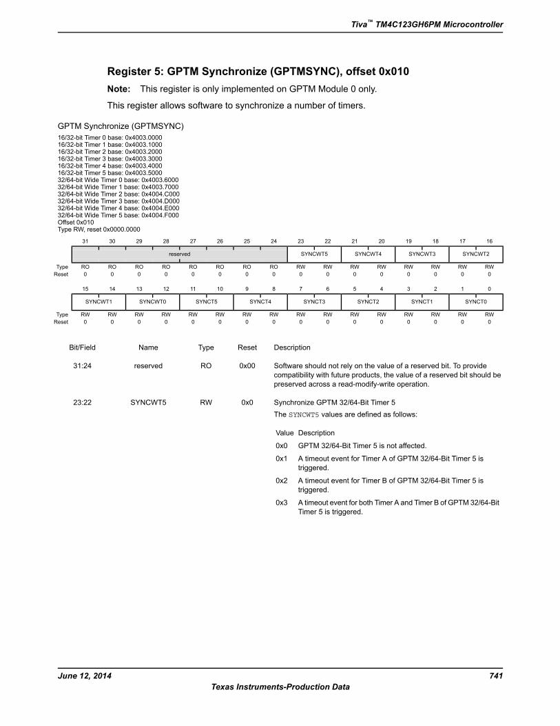
Register 5: GPTM Synchronize (GPTMSYNC), offset 0x010
Note: This register is only implemented on GPTM Module 0 only.
This register allows software to synchronize a number of timers.
GPTM Synchronize (GPTMSYNC)
16/32-bit Timer 0 base: 0x4003.000016/32-bit Timer 1 base: 0x4003.100016/32-bit Timer 2 base: 0x4003.200016/32-bit Timer 3 base: 0x4003.300016/32-bit Timer 4 base: 0x4003.400016/32-bit Timer 5 base: 0x4003.500032/64-bit Wide Timer 0 base: 0x4003.600032/64-bit Wide Timer 1 base: 0x4003.700032/64-bit Wide Timer 2 base: 0x4004.C00032/64-bit Wide Timer 3 base: 0x4004.D00032/64-bit Wide Timer 4 base: 0x4004.E00032/64-bit Wide Timer 5 base: 0x4004.F000Offset 0x010Type RW, reset 0x0000.0000
16171819202122232425262728293031
SYNCWT2SYNCWT3SYNCWT4SYNCWT5reserved
RWRWRWRWRWRWRWRWROROROROROROROROType
0000000000000000Reset
0123456789101112131415
SYNCT0SYNCT1SYNCT2SYNCT3SYNCT4SYNCT5SYNCWT0SYNCWT1
RWRWRWRWRWRWRWRWRWRWRWRWRWRWRWRWType
0000000000000000Reset
DescriptionResetTypeNameBit/Field
Software should not rely on the value of a reserved bit. To provide
compatibility with future products, the value of a reserved bit should be
preserved across a read-modify-write operation.
0x00ROreserved31:24
Synchronize GPTM 32/64-Bit Timer 5
The SYNCWT5 values are defined as follows:
DescriptionValue
GPTM 32/64-Bit Timer 5 is not affected.0x0
A timeout event for Timer A of GPTM 32/64-Bit Timer 5 is
triggered.
0x1
A timeout event for Timer B of GPTM 32/64-Bit Timer 5 is
triggered.
0x2
A timeout event for both Timer A and Timer B of GPTM 32/64-Bit
Timer 5 is triggered.
0x3
0x0RWSYNCWT523:22
741June 12, 2014
Texas Instruments-Production Data
Tiva™ TM4C123GH6PM Microcontroller
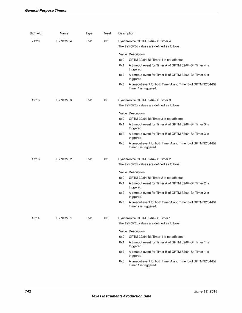
DescriptionResetTypeNameBit/Field
Synchronize GPTM 32/64-Bit Timer 4
The SYNCWT4 values are defined as follows:
DescriptionValue
GPTM 32/64-Bit Timer 4 is not affected.0x0
A timeout event for Timer A of GPTM 32/64-Bit Timer 4 is
triggered.
0x1
A timeout event for Timer B of GPTM 32/64-Bit Timer 4 is
triggered.
0x2
A timeout event for both Timer A and Timer B of GPTM 32/64-Bit
Timer 4 is triggered.
0x3
0x0RWSYNCWT421:20
Synchronize GPTM 32/64-Bit Timer 3
The SYNCWT3 values are defined as follows:
DescriptionValue
GPTM 32/64-Bit Timer 3 is not affected.0x0
A timeout event for Timer A of GPTM 32/64-Bit Timer 3 is
triggered.
0x1
A timeout event for Timer B of GPTM 32/64-Bit Timer 3 is
triggered.
0x2
A timeout event for both Timer A and Timer B of GPTM 32/64-Bit
Timer 3 is triggered.
0x3
0x0RWSYNCWT319:18
Synchronize GPTM 32/64-Bit Timer 2
The SYNCWT2 values are defined as follows:
DescriptionValue
GPTM 32/64-Bit Timer 2 is not affected.0x0
A timeout event for Timer A of GPTM 32/64-Bit Timer 2 is
triggered.
0x1
A timeout event for Timer B of GPTM 32/64-Bit Timer 2 is
triggered.
0x2
A timeout event for both Timer A and Timer B of GPTM 32/64-Bit
Timer 2 is triggered.
0x3
0x0RWSYNCWT217:16
Synchronize GPTM 32/64-Bit Timer 1
The SYNCWT1 values are defined as follows:
DescriptionValue
GPTM 32/64-Bit Timer 1 is not affected.0x0
A timeout event for Timer A of GPTM 32/64-Bit Timer 1 is
triggered.
0x1
A timeout event for Timer B of GPTM 32/64-Bit Timer 1 is
triggered.
0x2
A timeout event for both Timer A and Timer B of GPTM 32/64-Bit
Timer 1 is triggered.
0x3
0x0RWSYNCWT115:14
June 12, 2014742
Texas Instruments-Production Data
General-Purpose Timers
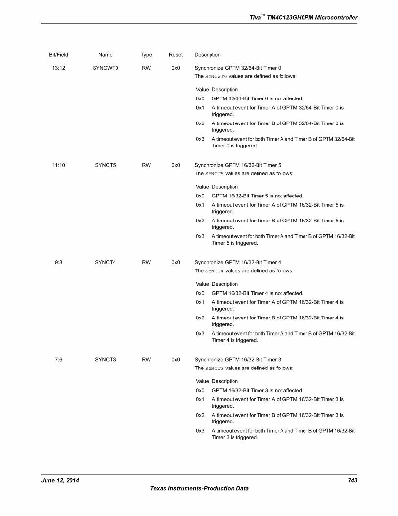
DescriptionResetTypeNameBit/Field
Synchronize GPTM 32/64-Bit Timer 0
The SYNCWT0 values are defined as follows:
DescriptionValue
GPTM 32/64-Bit Timer 0 is not affected.0x0
A timeout event for Timer A of GPTM 32/64-Bit Timer 0 is
triggered.
0x1
A timeout event for Timer B of GPTM 32/64-Bit Timer 0 is
triggered.
0x2
A timeout event for both Timer A and Timer B of GPTM 32/64-Bit
Timer 0 is triggered.
0x3
0x0RWSYNCWT013:12
Synchronize GPTM 16/32-Bit Timer 5
The SYNCT5 values are defined as follows:
DescriptionValue
GPTM 16/32-Bit Timer 5 is not affected.0x0
A timeout event for Timer A of GPTM 16/32-Bit Timer 5 is
triggered.
0x1
A timeout event for Timer B of GPTM 16/32-Bit Timer 5 is
triggered.
0x2
A timeout event for both Timer A and Timer B of GPTM 16/32-Bit
Timer 5 is triggered.
0x3
0x0RWSYNCT511:10
Synchronize GPTM 16/32-Bit Timer 4
The SYNCT4 values are defined as follows:
DescriptionValue
GPTM 16/32-Bit Timer 4 is not affected.0x0
A timeout event for Timer A of GPTM 16/32-Bit Timer 4 is
triggered.
0x1
A timeout event for Timer B of GPTM 16/32-Bit Timer 4 is
triggered.
0x2
A timeout event for both Timer A and Timer B of GPTM 16/32-Bit
Timer 4 is triggered.
0x3
0x0RWSYNCT49:8
Synchronize GPTM 16/32-Bit Timer 3
The SYNCT3 values are defined as follows:
DescriptionValue
GPTM 16/32-Bit Timer 3 is not affected.0x0
A timeout event for Timer A of GPTM 16/32-Bit Timer 3 is
triggered.
0x1
A timeout event for Timer B of GPTM 16/32-Bit Timer 3 is
triggered.
0x2
A timeout event for both Timer A and Timer B of GPTM 16/32-Bit
Timer 3 is triggered.
0x3
0x0RWSYNCT37:6
743June 12, 2014
Texas Instruments-Production Data
Tiva™ TM4C123GH6PM Microcontroller
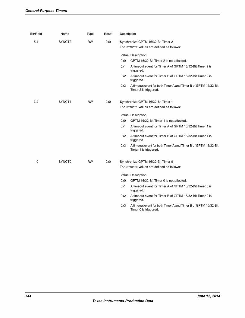
DescriptionResetTypeNameBit/Field
Synchronize GPTM 16/32-Bit Timer 2
The SYNCT2 values are defined as follows:
DescriptionValue
GPTM 16/32-Bit Timer 2 is not affected.0x0
A timeout event for Timer A of GPTM 16/32-Bit Timer 2 is
triggered.
0x1
A timeout event for Timer B of GPTM 16/32-Bit Timer 2 is
triggered.
0x2
A timeout event for both Timer A and Timer B of GPTM 16/32-Bit
Timer 2 is triggered.
0x3
0x0RWSYNCT25:4
Synchronize GPTM 16/32-Bit Timer 1
The SYNCT1 values are defined as follows:
DescriptionValue
GPTM 16/32-Bit Timer 1 is not affected.0x0
A timeout event for Timer A of GPTM 16/32-Bit Timer 1 is
triggered.
0x1
A timeout event for Timer B of GPTM 16/32-Bit Timer 1 is
triggered.
0x2
A timeout event for both Timer A and Timer B of GPTM 16/32-Bit
Timer 1 is triggered.
0x3
0x0RWSYNCT13:2
Synchronize GPTM 16/32-Bit Timer 0
The SYNCT0 values are defined as follows:
DescriptionValue
GPTM 16/32-Bit Timer 0 is not affected.0x0
A timeout event for Timer A of GPTM 16/32-Bit Timer 0 is
triggered.
0x1
A timeout event for Timer B of GPTM 16/32-Bit Timer 0 is
triggered.
0x2
A timeout event for both Timer A and Timer B of GPTM 16/32-Bit
Timer 0 is triggered.
0x3
0x0RWSYNCT01:0
June 12, 2014744
Texas Instruments-Production Data
General-Purpose Timers
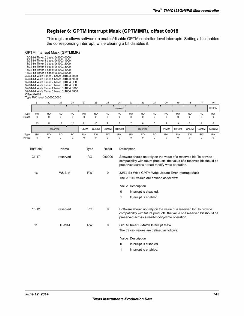
Register 6: GPTM Interrupt Mask (GPTMIMR), offset 0x018
This register allows software to enable/disable GPTM controller-level interrupts. Setting a bit enables
the corresponding interrupt, while clearing a bit disables it.
GPTM Interrupt Mask (GPTMIMR)
16/32-bit Timer 0 base: 0x4003.000016/32-bit Timer 1 base: 0x4003.100016/32-bit Timer 2 base: 0x4003.200016/32-bit Timer 3 base: 0x4003.300016/32-bit Timer 4 base: 0x4003.400016/32-bit Timer 5 base: 0x4003.500032/64-bit Wide Timer 0 base: 0x4003.600032/64-bit Wide Timer 1 base: 0x4003.700032/64-bit Wide Timer 2 base: 0x4004.C00032/64-bit Wide Timer 3 base: 0x4004.D00032/64-bit Wide Timer 4 base: 0x4004.E00032/64-bit Wide Timer 5 base: 0x4004.F000Offset 0x018Type RW, reset 0x0000.0000
16171819202122232425262728293031
WUEIMreserved
RWROROROROROROROROROROROROROROROType
0000000000000000Reset
0123456789101112131415
TATOIMCAMIMCAEIMRTCIMTAMIMreservedTBTOIMCBMIMCBEIMTBMIMreserved
RWRWRWRWRWRORORORWRWRWRWROROROROType
0000000000000000Reset
DescriptionResetTypeNameBit/Field
Software should not rely on the value of a reserved bit. To provide
compatibility with future products, the value of a reserved bit should be
preserved across a read-modify-write operation.
0x0000ROreserved31:17
32/64-Bit Wide GPTM Write Update Error Interrupt Mask
The WUEIM values are defined as follows:
DescriptionValue
Interrupt is disabled.0
Interrupt is enabled.1
0RWWUEIM16
Software should not rely on the value of a reserved bit. To provide
compatibility with future products, the value of a reserved bit should be
preserved across a read-modify-write operation.
0ROreserved15:12
GPTM Timer B Match Interrupt Mask
The TBMIM values are defined as follows:
DescriptionValue
Interrupt is disabled.0
Interrupt is enabled.1
0RWTBMIM11
745June 12, 2014
Texas Instruments-Production Data
Tiva™ TM4C123GH6PM Microcontroller
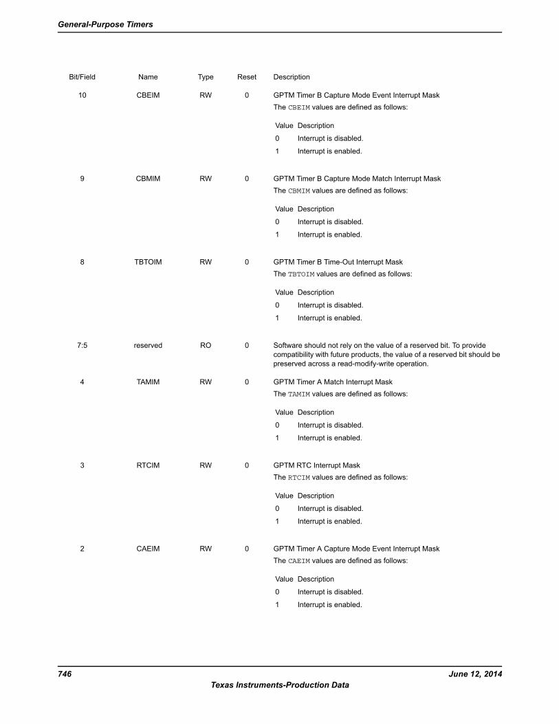
DescriptionResetTypeNameBit/Field
GPTM Timer B Capture Mode Event Interrupt Mask
The CBEIM values are defined as follows:
DescriptionValue
Interrupt is disabled.0
Interrupt is enabled.1
0RWCBEIM10
GPTM Timer B Capture Mode Match Interrupt Mask
The CBMIM values are defined as follows:
DescriptionValue
Interrupt is disabled.0
Interrupt is enabled.1
0RWCBMIM9
GPTM Timer B Time-Out Interrupt Mask
The TBTOIM values are defined as follows:
DescriptionValue
Interrupt is disabled.0
Interrupt is enabled.1
0RWTBTOIM8
Software should not rely on the value of a reserved bit. To provide
compatibility with future products, the value of a reserved bit should be
preserved across a read-modify-write operation.
0ROreserved7:5
GPTM Timer A Match Interrupt Mask
The TAMIM values are defined as follows:
DescriptionValue
Interrupt is disabled.0
Interrupt is enabled.1
0RWTAMIM4
GPTM RTC Interrupt Mask
The RTCIM values are defined as follows:
DescriptionValue
Interrupt is disabled.0
Interrupt is enabled.1
0RWRTCIM3
GPTM Timer A Capture Mode Event Interrupt Mask
The CAEIM values are defined as follows:
DescriptionValue
Interrupt is disabled.0
Interrupt is enabled.1
0RWCAEIM2
June 12, 2014746
Texas Instruments-Production Data
General-Purpose Timers

DescriptionResetTypeNameBit/Field
GPTM Timer A Capture Mode Match Interrupt Mask
The CAMIM values are defined as follows:
DescriptionValue
Interrupt is disabled.0
Interrupt is enabled.1
0RWCAMIM1
GPTM Timer A Time-Out Interrupt Mask
The TATOIM values are defined as follows:
DescriptionValue
Interrupt is disabled.0
Interrupt is enabled.1
0RWTATOIM0
747June 12, 2014
Texas Instruments-Production Data
Tiva™ TM4C123GH6PM Microcontroller
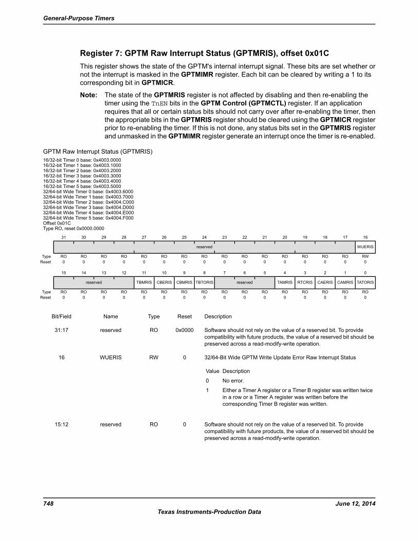
Register 7: GPTM Raw Interrupt Status (GPTMRIS), offset 0x01C
This register shows the state of the GPTM's internal interrupt signal. These bits are set whether or
not the interrupt is masked in the GPTMIMR register. Each bit can be cleared by writing a 1 to its
corresponding bit in GPTMICR.
Note: The state of the GPTMRIS register is not affected by disabling and then re-enabling the
timer using the TnEN bits in the GPTM Control (GPTMCTL) register. If an application
requires that all or certain status bits should not carry over after re-enabling the timer, then
the appropriate bits in theGPTMRIS register should be cleared using theGPTMICR register
prior to re-enabling the timer. If this is not done, any status bits set in the GPTMRIS register
and unmasked in theGPTMIMR register generate an interrupt once the timer is re-enabled.
GPTM Raw Interrupt Status (GPTMRIS)
16/32-bit Timer 0 base: 0x4003.000016/32-bit Timer 1 base: 0x4003.100016/32-bit Timer 2 base: 0x4003.200016/32-bit Timer 3 base: 0x4003.300016/32-bit Timer 4 base: 0x4003.400016/32-bit Timer 5 base: 0x4003.500032/64-bit Wide Timer 0 base: 0x4003.600032/64-bit Wide Timer 1 base: 0x4003.700032/64-bit Wide Timer 2 base: 0x4004.C00032/64-bit Wide Timer 3 base: 0x4004.D00032/64-bit Wide Timer 4 base: 0x4004.E00032/64-bit Wide Timer 5 base: 0x4004.F000Offset 0x01CType RO, reset 0x0000.0000
16171819202122232425262728293031
WUERISreserved
RWROROROROROROROROROROROROROROROType
0000000000000000Reset
0123456789101112131415
TATORISCAMRISCAERISRTCRISTAMRISreservedTBTORISCBMRISCBERISTBMRISreserved
ROROROROROROROROROROROROROROROROType
0000000000000000Reset
DescriptionResetTypeNameBit/Field
Software should not rely on the value of a reserved bit. To provide
compatibility with future products, the value of a reserved bit should be
preserved across a read-modify-write operation.
0x0000ROreserved31:17
32/64-Bit Wide GPTM Write Update Error Raw Interrupt Status
DescriptionValue
No error.0
Either a Timer A register or a Timer B register was written twice
in a row or a Timer A register was written before the
corresponding Timer B register was written.
1
0RWWUERIS16
Software should not rely on the value of a reserved bit. To provide
compatibility with future products, the value of a reserved bit should be
preserved across a read-modify-write operation.
0ROreserved15:12
June 12, 2014748
Texas Instruments-Production Data
General-Purpose Timers
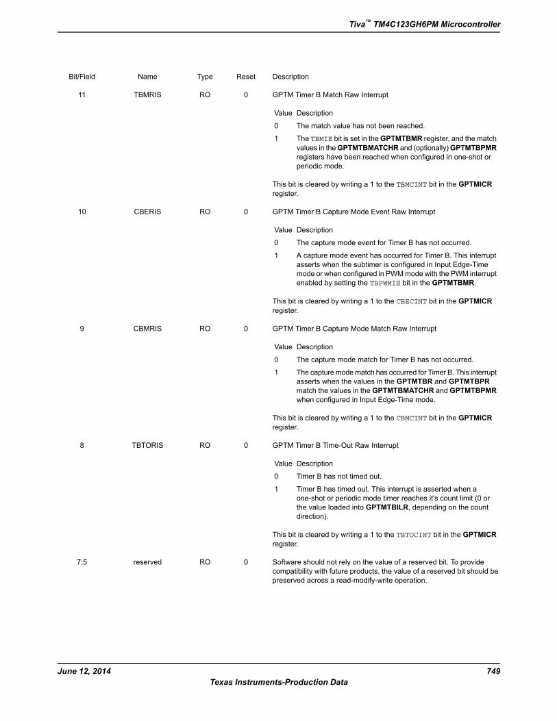
DescriptionResetTypeNameBit/Field
GPTM Timer B Match Raw Interrupt
DescriptionValue
The match value has not been reached.0
The TBMIE bit is set in theGPTMTBMR register, and the match
values in theGPTMTBMATCHR and (optionally)GPTMTBPMR
registers have been reached when configured in one-shot or
periodic mode.
1
This bit is cleared by writing a 1 to the TBMCINT bit in the GPTMICR
register.
0ROTBMRIS11
GPTM Timer B Capture Mode Event Raw Interrupt
DescriptionValue
The capture mode event for Timer B has not occurred.0
A capture mode event has occurred for Timer B. This interrupt
asserts when the subtimer is configured in Input Edge-Time
mode or when configured in PWMmode with the PWM interrupt
enabled by setting the TBPWMIE bit in the GPTMTBMR.
1
This bit is cleared by writing a 1 to the CBECINT bit in the GPTMICR
register.
0ROCBERIS10
GPTM Timer B Capture Mode Match Raw Interrupt
DescriptionValue
The capture mode match for Timer B has not occurred.0
The capturemodematch has occurred for Timer B. This interrupt
asserts when the values in the GPTMTBR and GPTMTBPR
match the values in the GPTMTBMATCHR and GPTMTBPMR
when configured in Input Edge-Time mode.
1
This bit is cleared by writing a 1 to the CBMCINT bit in the GPTMICR
register.
0ROCBMRIS9
GPTM Timer B Time-Out Raw Interrupt
DescriptionValue
Timer B has not timed out.0
Timer B has timed out. This interrupt is asserted when a
one-shot or periodic mode timer reaches it's count limit (0 or
the value loaded into GPTMTBILR, depending on the count
direction).
1
This bit is cleared by writing a 1 to the TBTOCINT bit in the GPTMICR
register.
0ROTBTORIS8
Software should not rely on the value of a reserved bit. To provide
compatibility with future products, the value of a reserved bit should be
preserved across a read-modify-write operation.
0ROreserved7:5
749June 12, 2014
Texas Instruments-Production Data
Tiva™ TM4C123GH6PM Microcontroller
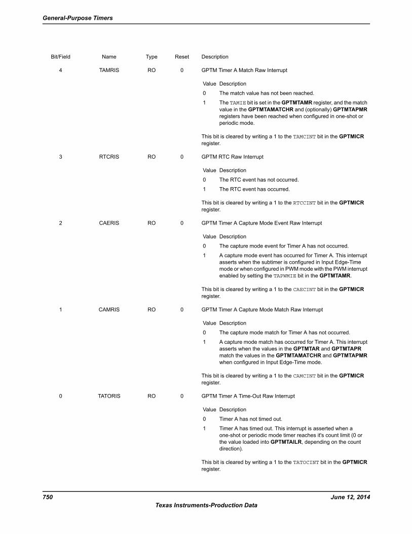
DescriptionResetTypeNameBit/Field
GPTM Timer A Match Raw Interrupt
DescriptionValue
The match value has not been reached.0
The TAMIE bit is set in theGPTMTAMR register, and the match
value in the GPTMTAMATCHR and (optionally) GPTMTAPMR
registers have been reached when configured in one-shot or
periodic mode.
1
This bit is cleared by writing a 1 to the TAMCINT bit in the GPTMICR
register.
0ROTAMRIS4
GPTM RTC Raw Interrupt
DescriptionValue
The RTC event has not occurred.0
The RTC event has occurred.1
This bit is cleared by writing a 1 to the RTCCINT bit in the GPTMICR
register.
0RORTCRIS3
GPTM Timer A Capture Mode Event Raw Interrupt
DescriptionValue
The capture mode event for Timer A has not occurred.0
A capture mode event has occurred for Timer A. This interrupt
asserts when the subtimer is configured in Input Edge-Time
mode or when configured in PWMmode with the PWM interrupt
enabled by setting the TAPWMIE bit in the GPTMTAMR.
1
This bit is cleared by writing a 1 to the CAECINT bit in the GPTMICR
register.
0ROCAERIS2
GPTM Timer A Capture Mode Match Raw Interrupt
DescriptionValue
The capture mode match for Timer A has not occurred.0
A capture mode match has occurred for Timer A. This interrupt
asserts when the values in the GPTMTAR and GPTMTAPR
match the values in the GPTMTAMATCHR and GPTMTAPMR
when configured in Input Edge-Time mode.
1
This bit is cleared by writing a 1 to the CAMCINT bit in the GPTMICR
register.
0ROCAMRIS1
GPTM Timer A Time-Out Raw Interrupt
DescriptionValue
Timer A has not timed out.0
Timer A has timed out. This interrupt is asserted when a
one-shot or periodic mode timer reaches it's count limit (0 or
the value loaded into GPTMTAILR, depending on the count
direction).
1
This bit is cleared by writing a 1 to the TATOCINT bit in the GPTMICR
register.
0ROTATORIS0
June 12, 2014750
Texas Instruments-Production Data
General-Purpose Timers

Register 8: GPTM Masked Interrupt Status (GPTMMIS), offset 0x020
This register show the state of the GPTM's controller-level interrupt. If an interrupt is unmasked in
GPTMIMR, and there is an event that causes the interrupt to be asserted, the corresponding bit is
set in this register. All bits are cleared by writing a 1 to the corresponding bit in GPTMICR.
GPTM Masked Interrupt Status (GPTMMIS)
16/32-bit Timer 0 base: 0x4003.000016/32-bit Timer 1 base: 0x4003.100016/32-bit Timer 2 base: 0x4003.200016/32-bit Timer 3 base: 0x4003.300016/32-bit Timer 4 base: 0x4003.400016/32-bit Timer 5 base: 0x4003.500032/64-bit Wide Timer 0 base: 0x4003.600032/64-bit Wide Timer 1 base: 0x4003.700032/64-bit Wide Timer 2 base: 0x4004.C00032/64-bit Wide Timer 3 base: 0x4004.D00032/64-bit Wide Timer 4 base: 0x4004.E00032/64-bit Wide Timer 5 base: 0x4004.F000Offset 0x020Type RO, reset 0x0000.0000
16171819202122232425262728293031
WUEMISreserved
ROROROROROROROROROROROROROROROROType
0000000000000000Reset
0123456789101112131415
TATOMISCAMMISCAEMISRTCMISTAMMISreservedTBTOMISCBMMISCBEMISTBMMISreserved
ROROROROROROROROROROROROROROROROType
0000000000000000Reset
DescriptionResetTypeNameBit/Field
Software should not rely on the value of a reserved bit. To provide
compatibility with future products, the value of a reserved bit should be
preserved across a read-modify-write operation.
0x0000ROreserved31:17
32/64-Bit Wide GPTM Write Update Error Masked Interrupt Status
DescriptionValue
An unmasked Write Update Error has not occurred.0
An unmasked Write Update Error has occurred.1
0ROWUEMIS16
Software should not rely on the value of a reserved bit. To provide
compatibility with future products, the value of a reserved bit should be
preserved across a read-modify-write operation.
0ROreserved15:12
GPTM Timer B Match Masked Interrupt
DescriptionValue
A Timer B Mode Match interrupt has not occurred or is masked.0
An unmasked Timer B Mode Match interrupt
has occurred.
1
This bit is cleared by writing a 1 to the TBMCINT bit in the GPTMICR
register.
0ROTBMMIS11
751June 12, 2014
Texas Instruments-Production Data
Tiva™ TM4C123GH6PM Microcontroller
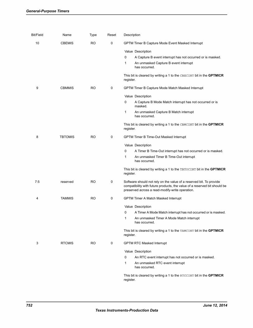
DescriptionResetTypeNameBit/Field
GPTM Timer B Capture Mode Event Masked Interrupt
DescriptionValue
A Capture B event interrupt has not occurred or is masked.0
An unmasked Capture B event interrupt
has occurred.
1
This bit is cleared by writing a 1 to the CBECINT bit in the GPTMICR
register.
0ROCBEMIS10
GPTM Timer B Capture Mode Match Masked Interrupt
DescriptionValue
A Capture B Mode Match interrupt has not occurred or is
masked.
0
An unmasked Capture B Match interrupt
has occurred.
1
This bit is cleared by writing a 1 to the CBMCINT bit in the GPTMICR
register.
0ROCBMMIS9
GPTM Timer B Time-Out Masked Interrupt
DescriptionValue
A Timer B Time-Out interrupt has not occurred or is masked.0
An unmasked Timer B Time-Out interrupt
has occurred.
1
This bit is cleared by writing a 1 to the TBTOCINT bit in the GPTMICR
register.
0ROTBTOMIS8
Software should not rely on the value of a reserved bit. To provide
compatibility with future products, the value of a reserved bit should be
preserved across a read-modify-write operation.
0ROreserved7:5
GPTM Timer A Match Masked Interrupt
DescriptionValue
A Timer A Mode Match interrupt has not occurred or is masked.0
An unmasked Timer A Mode Match interrupt
has occurred.
1
This bit is cleared by writing a 1 to the TAMCINT bit in the GPTMICR
register.
0ROTAMMIS4
GPTM RTC Masked Interrupt
DescriptionValue
An RTC event interrupt has not occurred or is masked.0
An unmasked RTC event interrupt
has occurred.
1
This bit is cleared by writing a 1 to the RTCCINT bit in the GPTMICR
register.
0RORTCMIS3
June 12, 2014752
Texas Instruments-Production Data
General-Purpose Timers
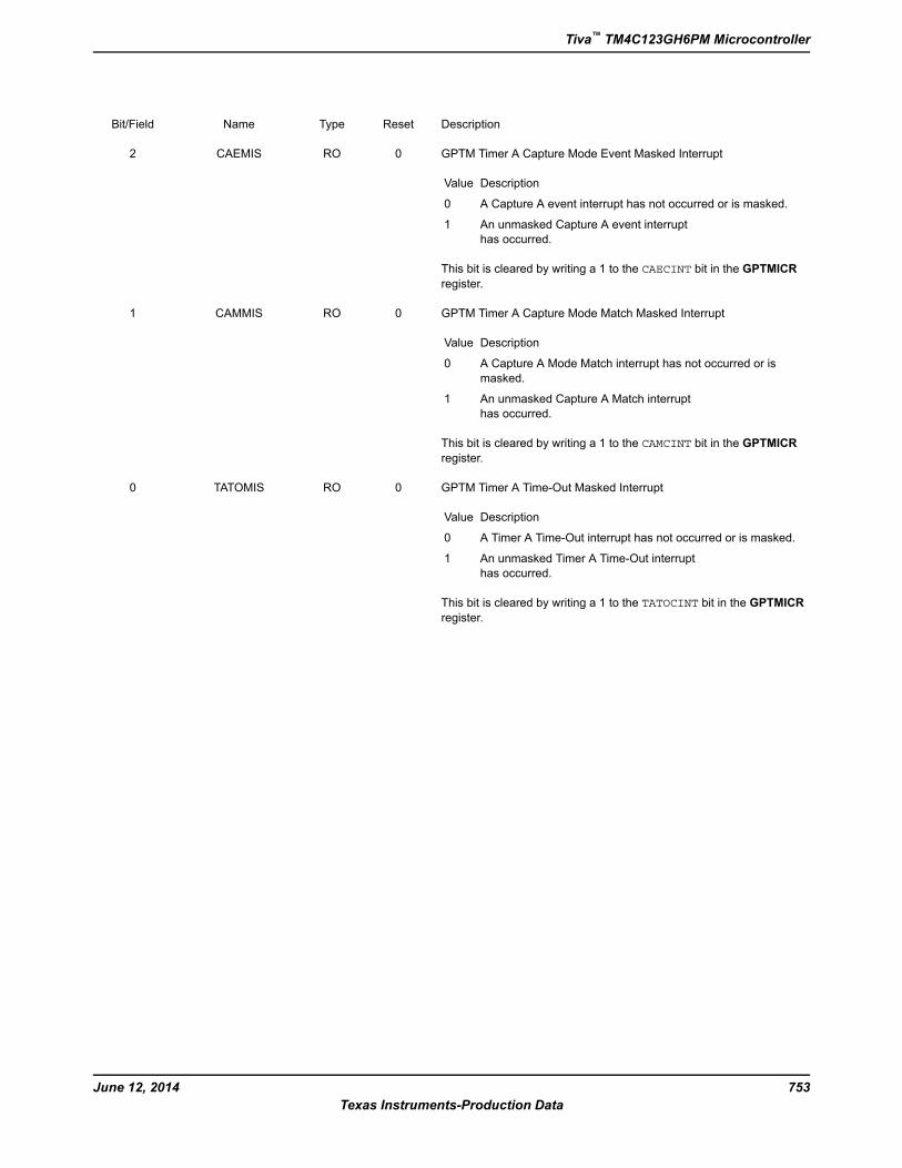
DescriptionResetTypeNameBit/Field
GPTM Timer A Capture Mode Event Masked Interrupt
DescriptionValue
A Capture A event interrupt has not occurred or is masked.0
An unmasked Capture A event interrupt
has occurred.
1
This bit is cleared by writing a 1 to the CAECINT bit in the GPTMICR
register.
0ROCAEMIS2
GPTM Timer A Capture Mode Match Masked Interrupt
DescriptionValue
A Capture A Mode Match interrupt has not occurred or is
masked.
0
An unmasked Capture A Match interrupt
has occurred.
1
This bit is cleared by writing a 1 to the CAMCINT bit in the GPTMICR
register.
0ROCAMMIS1
GPTM Timer A Time-Out Masked Interrupt
DescriptionValue
A Timer A Time-Out interrupt has not occurred or is masked.0
An unmasked Timer A Time-Out interrupt
has occurred.
1
This bit is cleared by writing a 1 to the TATOCINT bit in the GPTMICR
register.
0ROTATOMIS0
753June 12, 2014
Texas Instruments-Production Data
Tiva™ TM4C123GH6PM Microcontroller
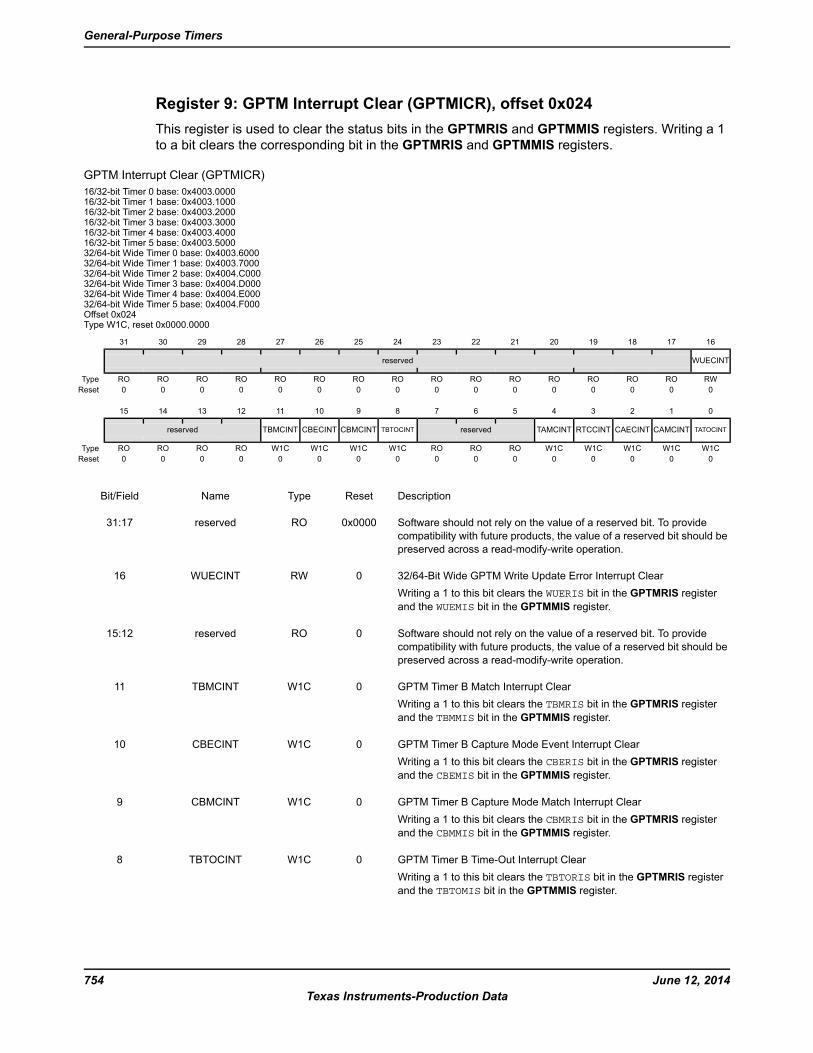
Register 9: GPTM Interrupt Clear (GPTMICR), offset 0x024
This register is used to clear the status bits in the GPTMRIS and GPTMMIS registers. Writing a 1
to a bit clears the corresponding bit in the GPTMRIS and GPTMMIS registers.
GPTM Interrupt Clear (GPTMICR)
16/32-bit Timer 0 base: 0x4003.000016/32-bit Timer 1 base: 0x4003.100016/32-bit Timer 2 base: 0x4003.200016/32-bit Timer 3 base: 0x4003.300016/32-bit Timer 4 base: 0x4003.400016/32-bit Timer 5 base: 0x4003.500032/64-bit Wide Timer 0 base: 0x4003.600032/64-bit Wide Timer 1 base: 0x4003.700032/64-bit Wide Timer 2 base: 0x4004.C00032/64-bit Wide Timer 3 base: 0x4004.D00032/64-bit Wide Timer 4 base: 0x4004.E00032/64-bit Wide Timer 5 base: 0x4004.F000Offset 0x024Type W1C, reset 0x0000.0000
16171819202122232425262728293031
WUECINTreserved
RWROROROROROROROROROROROROROROROType
0000000000000000Reset
0123456789101112131415
TATOCINTCAMCINTCAECINTRTCCINTTAMCINTreservedTBTOCINTCBMCINTCBECINTTBMCINTreserved
W1CW1CW1CW1CW1CROROROW1CW1CW1CW1CROROROROType
0000000000000000Reset
DescriptionResetTypeNameBit/Field
Software should not rely on the value of a reserved bit. To provide
compatibility with future products, the value of a reserved bit should be
preserved across a read-modify-write operation.
0x0000ROreserved31:17
32/64-Bit Wide GPTM Write Update Error Interrupt Clear
Writing a 1 to this bit clears the WUERIS bit in the GPTMRIS register
and the WUEMIS bit in the GPTMMIS register.
0RWWUECINT16
Software should not rely on the value of a reserved bit. To provide
compatibility with future products, the value of a reserved bit should be
preserved across a read-modify-write operation.
0ROreserved15:12
GPTM Timer B Match Interrupt Clear
Writing a 1 to this bit clears the TBMRIS bit in the GPTMRIS register
and the TBMMIS bit in the GPTMMIS register.
0W1CTBMCINT11
GPTM Timer B Capture Mode Event Interrupt Clear
Writing a 1 to this bit clears the CBERIS bit in the GPTMRIS register
and the CBEMIS bit in the GPTMMIS register.
0W1CCBECINT10
GPTM Timer B Capture Mode Match Interrupt Clear
Writing a 1 to this bit clears the CBMRIS bit in the GPTMRIS register
and the CBMMIS bit in the GPTMMIS register.
0W1CCBMCINT9
GPTM Timer B Time-Out Interrupt Clear
Writing a 1 to this bit clears the TBTORIS bit in the GPTMRIS register
and the TBTOMIS bit in the GPTMMIS register.
0W1CTBTOCINT8
June 12, 2014754
Texas Instruments-Production Data
General-Purpose Timers
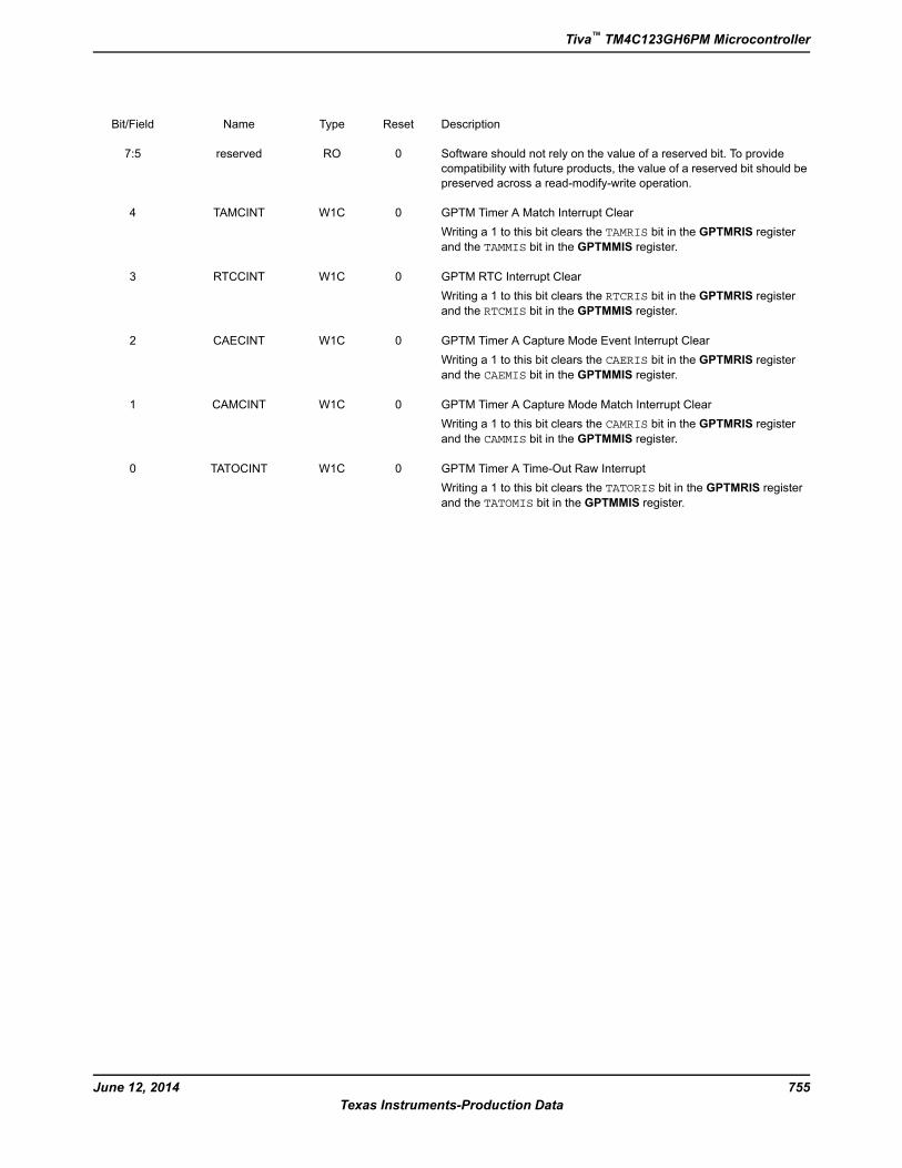
DescriptionResetTypeNameBit/Field
Software should not rely on the value of a reserved bit. To provide
compatibility with future products, the value of a reserved bit should be
preserved across a read-modify-write operation.
0ROreserved7:5
GPTM Timer A Match Interrupt Clear
Writing a 1 to this bit clears the TAMRIS bit in the GPTMRIS register
and the TAMMIS bit in the GPTMMIS register.
0W1CTAMCINT4
GPTM RTC Interrupt Clear
Writing a 1 to this bit clears the RTCRIS bit in the GPTMRIS register
and the RTCMIS bit in the GPTMMIS register.
0W1CRTCCINT3
GPTM Timer A Capture Mode Event Interrupt Clear
Writing a 1 to this bit clears the CAERIS bit in the GPTMRIS register
and the CAEMIS bit in the GPTMMIS register.
0W1CCAECINT2
GPTM Timer A Capture Mode Match Interrupt Clear
Writing a 1 to this bit clears the CAMRIS bit in the GPTMRIS register
and the CAMMIS bit in the GPTMMIS register.
0W1CCAMCINT1
GPTM Timer A Time-Out Raw Interrupt
Writing a 1 to this bit clears the TATORIS bit in the GPTMRIS register
and the TATOMIS bit in the GPTMMIS register.
0W1CTATOCINT0
755June 12, 2014
Texas Instruments-Production Data
Tiva™ TM4C123GH6PM Microcontroller
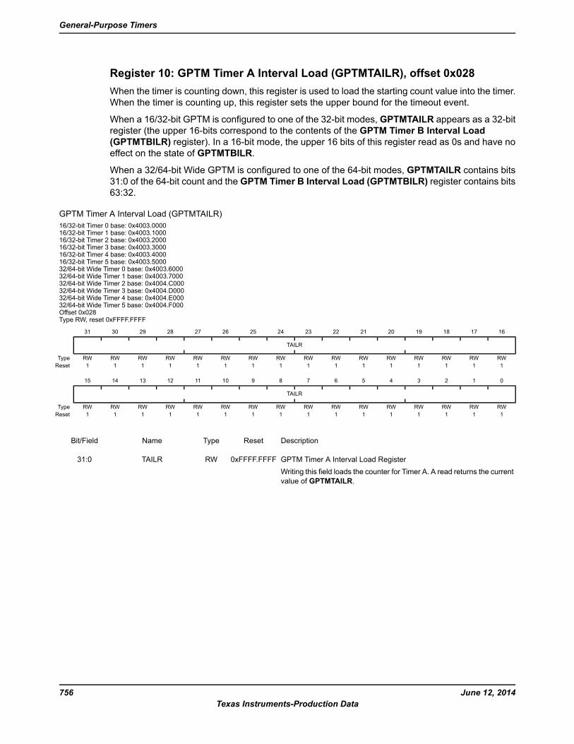
Register 10: GPTM Timer A Interval Load (GPTMTAILR), offset 0x028
When the timer is counting down, this register is used to load the starting count value into the timer.
When the timer is counting up, this register sets the upper bound for the timeout event.
When a 16/32-bit GPTM is configured to one of the 32-bit modes, GPTMTAILR appears as a 32-bit
register (the upper 16-bits correspond to the contents of the GPTM Timer B Interval Load
(GPTMTBILR) register). In a 16-bit mode, the upper 16 bits of this register read as 0s and have no
effect on the state of GPTMTBILR.
When a 32/64-bit Wide GPTM is configured to one of the 64-bit modes, GPTMTAILR contains bits
31:0 of the 64-bit count and the GPTM Timer B Interval Load (GPTMTBILR) register contains bits
63:32.
GPTM Timer A Interval Load (GPTMTAILR)
16/32-bit Timer 0 base: 0x4003.000016/32-bit Timer 1 base: 0x4003.100016/32-bit Timer 2 base: 0x4003.200016/32-bit Timer 3 base: 0x4003.300016/32-bit Timer 4 base: 0x4003.400016/32-bit Timer 5 base: 0x4003.500032/64-bit Wide Timer 0 base: 0x4003.600032/64-bit Wide Timer 1 base: 0x4003.700032/64-bit Wide Timer 2 base: 0x4004.C00032/64-bit Wide Timer 3 base: 0x4004.D00032/64-bit Wide Timer 4 base: 0x4004.E00032/64-bit Wide Timer 5 base: 0x4004.F000Offset 0x028Type RW, reset 0xFFFF.FFFF
16171819202122232425262728293031
TAILR
RWRWRWRWRWRWRWRWRWRWRWRWRWRWRWRWType
1111111111111111Reset
0123456789101112131415
TAILR
RWRWRWRWRWRWRWRWRWRWRWRWRWRWRWRWType
1111111111111111Reset
DescriptionResetTypeNameBit/Field
GPTM Timer A Interval Load Register
Writing this field loads the counter for Timer A. A read returns the current
value of GPTMTAILR.
0xFFFF.FFFFRWTAILR31:0
June 12, 2014756
Texas Instruments-Production Data
General-Purpose Timers
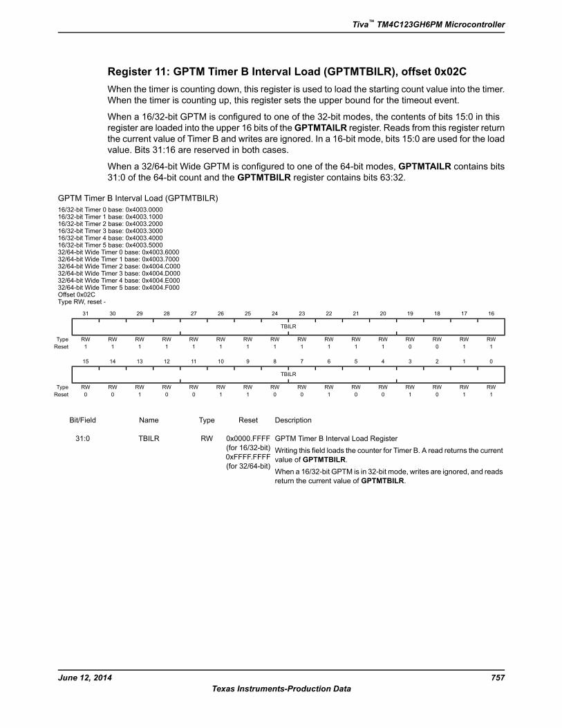
Register 11: GPTM Timer B Interval Load (GPTMTBILR), offset 0x02C
When the timer is counting down, this register is used to load the starting count value into the timer.
When the timer is counting up, this register sets the upper bound for the timeout event.
When a 16/32-bit GPTM is configured to one of the 32-bit modes, the contents of bits 15:0 in this
register are loaded into the upper 16 bits of theGPTMTAILR register. Reads from this register return
the current value of Timer B and writes are ignored. In a 16-bit mode, bits 15:0 are used for the load
value. Bits 31:16 are reserved in both cases.
When a 32/64-bit Wide GPTM is configured to one of the 64-bit modes, GPTMTAILR contains bits
31:0 of the 64-bit count and the GPTMTBILR register contains bits 63:32.
GPTM Timer B Interval Load (GPTMTBILR)
16/32-bit Timer 0 base: 0x4003.000016/32-bit Timer 1 base: 0x4003.100016/32-bit Timer 2 base: 0x4003.200016/32-bit Timer 3 base: 0x4003.300016/32-bit Timer 4 base: 0x4003.400016/32-bit Timer 5 base: 0x4003.500032/64-bit Wide Timer 0 base: 0x4003.600032/64-bit Wide Timer 1 base: 0x4003.700032/64-bit Wide Timer 2 base: 0x4004.C00032/64-bit Wide Timer 3 base: 0x4004.D00032/64-bit Wide Timer 4 base: 0x4004.E00032/64-bit Wide Timer 5 base: 0x4004.F000Offset 0x02CType RW, reset -
16171819202122232425262728293031
TBILR
RWRWRWRWRWRWRWRWRWRWRWRWRWRWRWRWType
1100111111111111Reset
0123456789101112131415
TBILR
RWRWRWRWRWRWRWRWRWRWRWRWRWRWRWRWType
1101001001100100Reset
DescriptionResetTypeNameBit/Field
GPTM Timer B Interval Load Register
Writing this field loads the counter for Timer B. A read returns the current
value of GPTMTBILR.
When a 16/32-bit GPTM is in 32-bit mode, writes are ignored, and reads
return the current value of GPTMTBILR.
0x0000.FFFF
(for 16/32-bit)
0xFFFF.FFFF
(for 32/64-bit)
RWTBILR31:0
757June 12, 2014
Texas Instruments-Production Data
Tiva™ TM4C123GH6PM Microcontroller
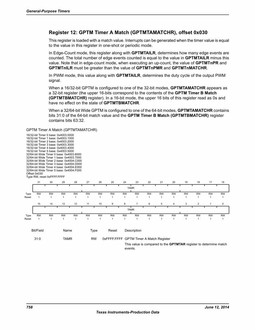
Register 12: GPTM Timer A Match (GPTMTAMATCHR), offset 0x030
This register is loaded with a match value. Interrupts can be generated when the timer value is equal
to the value in this register in one-shot or periodic mode.
In Edge-Count mode, this register along with GPTMTAILR, determines how many edge events are
counted. The total number of edge events counted is equal to the value in GPTMTAILR minus this
value. Note that in edge-count mode, when executing an up-count, the value of GPTMTnPR and
GPTMTnILR must be greater than the value of GPTMTnPMR and GPTMTnMATCHR.
In PWM mode, this value along with GPTMTAILR, determines the duty cycle of the output PWM
signal.
When a 16/32-bit GPTM is configured to one of the 32-bit modes, GPTMTAMATCHR appears as
a 32-bit register (the upper 16-bits correspond to the contents of the GPTM Timer B Match
(GPTMTBMATCHR) register). In a 16-bit mode, the upper 16 bits of this register read as 0s and
have no effect on the state of GPTMTBMATCHR.
When a 32/64-bit Wide GPTM is configured to one of the 64-bit modes,GPTMTAMATCHR contains
bits 31:0 of the 64-bit match value and the GPTM Timer B Match (GPTMTBMATCHR) register
contains bits 63:32.
GPTM Timer A Match (GPTMTAMATCHR)
16/32-bit Timer 0 base: 0x4003.000016/32-bit Timer 1 base: 0x4003.100016/32-bit Timer 2 base: 0x4003.200016/32-bit Timer 3 base: 0x4003.300016/32-bit Timer 4 base: 0x4003.400016/32-bit Timer 5 base: 0x4003.500032/64-bit Wide Timer 0 base: 0x4003.600032/64-bit Wide Timer 1 base: 0x4003.700032/64-bit Wide Timer 2 base: 0x4004.C00032/64-bit Wide Timer 3 base: 0x4004.D00032/64-bit Wide Timer 4 base: 0x4004.E00032/64-bit Wide Timer 5 base: 0x4004.F000Offset 0x030Type RW, reset 0xFFFF.FFFF
16171819202122232425262728293031
TAMR
RWRWRWRWRWRWRWRWRWRWRWRWRWRWRWRWType
1111111111111111Reset
0123456789101112131415
TAMR
RWRWRWRWRWRWRWRWRWRWRWRWRWRWRWRWType
1111111111111111Reset
DescriptionResetTypeNameBit/Field
GPTM Timer A Match Register
This value is compared to the GPTMTAR register to determine match
events.
0xFFFF.FFFFRWTAMR31:0
June 12, 2014758
Texas Instruments-Production Data
General-Purpose Timers
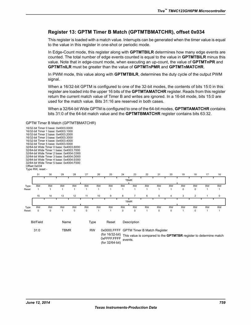
Register 13: GPTM Timer B Match (GPTMTBMATCHR), offset 0x034
This register is loaded with a match value. Interrupts can be generated when the timer value is equal
to the value in this register in one-shot or periodic mode.
In Edge-Count mode, this register along with GPTMTBILR determines how many edge events are
counted. The total number of edge events counted is equal to the value in GPTMTBILR minus this
value. Note that in edge-count mode, when executing an up-count, the value of GPTMTnPR and
GPTMTnILR must be greater than the value of GPTMTnPMR and GPTMTnMATCHR.
In PWM mode, this value along with GPTMTBILR, determines the duty cycle of the output PWM
signal.
When a 16/32-bit GPTM is configured to one of the 32-bit modes, the contents of bits 15:0 in this
register are loaded into the upper 16 bits of theGPTMTAMATCHR register. Reads from this register
return the current match value of Timer B and writes are ignored. In a 16-bit mode, bits 15:0 are
used for the match value. Bits 31:16 are reserved in both cases.
When a 32/64-bit Wide GPTM is configured to one of the 64-bit modes,GPTMTAMATCHR contains
bits 31:0 of the 64-bit match value and the GPTMTBMATCHR register contains bits 63:32.
GPTM Timer B Match (GPTMTBMATCHR)
16/32-bit Timer 0 base: 0x4003.000016/32-bit Timer 1 base: 0x4003.100016/32-bit Timer 2 base: 0x4003.200016/32-bit Timer 3 base: 0x4003.300016/32-bit Timer 4 base: 0x4003.400016/32-bit Timer 5 base: 0x4003.500032/64-bit Wide Timer 0 base: 0x4003.600032/64-bit Wide Timer 1 base: 0x4003.700032/64-bit Wide Timer 2 base: 0x4004.C00032/64-bit Wide Timer 3 base: 0x4004.D00032/64-bit Wide Timer 4 base: 0x4004.E00032/64-bit Wide Timer 5 base: 0x4004.F000Offset 0x034Type RW, reset -
16171819202122232425262728293031
TBMR
RWRWRWRWRWRWRWRWRWRWRWRWRWRWRWRWType
1100111111111111Reset
0123456789101112131415
TBMR
RWRWRWRWRWRWRWRWRWRWRWRWRWRWRWRWType
1101001001100100Reset
DescriptionResetTypeNameBit/Field
GPTM Timer B Match Register
This value is compared to the GPTMTBR register to determine match
events.
0x0000.FFFF
(for 16/32-bit)
0xFFFF.FFFF
(for 32/64-bit)
RWTBMR31:0
759June 12, 2014
Texas Instruments-Production Data
Tiva™ TM4C123GH6PM Microcontroller
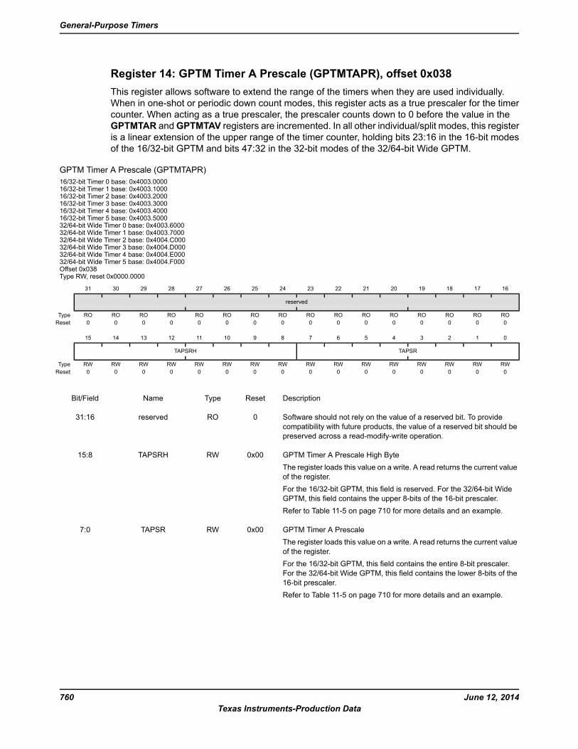
Register 14: GPTM Timer A Prescale (GPTMTAPR), offset 0x038
This register allows software to extend the range of the timers when they are used individually.
When in one-shot or periodic down count modes, this register acts as a true prescaler for the timer
counter. When acting as a true prescaler, the prescaler counts down to 0 before the value in the
GPTMTAR andGPTMTAV registers are incremented. In all other individual/split modes, this register
is a linear extension of the upper range of the timer counter, holding bits 23:16 in the 16-bit modes
of the 16/32-bit GPTM and bits 47:32 in the 32-bit modes of the 32/64-bit Wide GPTM.
GPTM Timer A Prescale (GPTMTAPR)
16/32-bit Timer 0 base: 0x4003.000016/32-bit Timer 1 base: 0x4003.100016/32-bit Timer 2 base: 0x4003.200016/32-bit Timer 3 base: 0x4003.300016/32-bit Timer 4 base: 0x4003.400016/32-bit Timer 5 base: 0x4003.500032/64-bit Wide Timer 0 base: 0x4003.600032/64-bit Wide Timer 1 base: 0x4003.700032/64-bit Wide Timer 2 base: 0x4004.C00032/64-bit Wide Timer 3 base: 0x4004.D00032/64-bit Wide Timer 4 base: 0x4004.E00032/64-bit Wide Timer 5 base: 0x4004.F000Offset 0x038Type RW, reset 0x0000.0000
16171819202122232425262728293031
reserved
ROROROROROROROROROROROROROROROROType
0000000000000000Reset
0123456789101112131415
TAPSRTAPSRH
RWRWRWRWRWRWRWRWRWRWRWRWRWRWRWRWType
0000000000000000Reset
DescriptionResetTypeNameBit/Field
Software should not rely on the value of a reserved bit. To provide
compatibility with future products, the value of a reserved bit should be
preserved across a read-modify-write operation.
0ROreserved31:16
GPTM Timer A Prescale High Byte
The register loads this value on a write. A read returns the current value
of the register.
For the 16/32-bit GPTM, this field is reserved. For the 32/64-bit Wide
GPTM, this field contains the upper 8-bits of the 16-bit prescaler.
Refer to Table 11-5 on page 710 for more details and an example.
0x00RWTAPSRH15:8
GPTM Timer A Prescale
The register loads this value on a write. A read returns the current value
of the register.
For the 16/32-bit GPTM, this field contains the entire 8-bit prescaler.
For the 32/64-bit Wide GPTM, this field contains the lower 8-bits of the
16-bit prescaler.
Refer to Table 11-5 on page 710 for more details and an example.
0x00RWTAPSR7:0
June 12, 2014760
Texas Instruments-Production Data
General-Purpose Timers
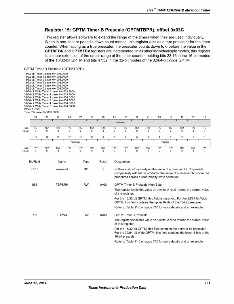
Register 15: GPTM Timer B Prescale (GPTMTBPR), offset 0x03C
This register allows software to extend the range of the timers when they are used individually.
When in one-shot or periodic down count modes, this register acts as a true prescaler for the timer
counter. When acting as a true prescaler, the prescaler counts down to 0 before the value in the
GPTMTBR andGPTMTBV registers are incremented. In all other individual/split modes, this register
is a linear extension of the upper range of the timer counter, holding bits 23:16 in the 16-bit modes
of the 16/32-bit GPTM and bits 47:32 in the 32-bit modes of the 32/64-bit Wide GPTM.
GPTM Timer B Prescale (GPTMTBPR)
16/32-bit Timer 0 base: 0x4003.000016/32-bit Timer 1 base: 0x4003.100016/32-bit Timer 2 base: 0x4003.200016/32-bit Timer 3 base: 0x4003.300016/32-bit Timer 4 base: 0x4003.400016/32-bit Timer 5 base: 0x4003.500032/64-bit Wide Timer 0 base: 0x4003.600032/64-bit Wide Timer 1 base: 0x4003.700032/64-bit Wide Timer 2 base: 0x4004.C00032/64-bit Wide Timer 3 base: 0x4004.D00032/64-bit Wide Timer 4 base: 0x4004.E00032/64-bit Wide Timer 5 base: 0x4004.F000Offset 0x03CType RW, reset 0x0000.0000
16171819202122232425262728293031
reserved
ROROROROROROROROROROROROROROROROType
0000000000000000Reset
0123456789101112131415
TBPSRTBPSRH
RWRWRWRWRWRWRWRWRWRWRWRWRWRWRWRWType
0000000000000000Reset
DescriptionResetTypeNameBit/Field
Software should not rely on the value of a reserved bit. To provide
compatibility with future products, the value of a reserved bit should be
preserved across a read-modify-write operation.
0ROreserved31:16
GPTM Timer B Prescale High Byte
The register loads this value on a write. A read returns the current value
of the register.
For the 16/32-bit GPTM, this field is reserved. For the 32/64-bit Wide
GPTM, this field contains the upper 8-bits of the 16-bit prescaler.
Refer to Table 11-5 on page 710 for more details and an example.
0x00RWTBPSRH15:8
GPTM Timer B Prescale
The register loads this value on a write. A read returns the current value
of this register.
For the 16/32-bit GPTM, this field contains the entire 8-bit prescaler.
For the 32/64-bit Wide GPTM, this field contains the lower 8-bits of the
16-bit prescaler.
Refer to Table 11-5 on page 710 for more details and an example.
0x00RWTBPSR7:0
761June 12, 2014
Texas Instruments-Production Data
Tiva™ TM4C123GH6PM Microcontroller
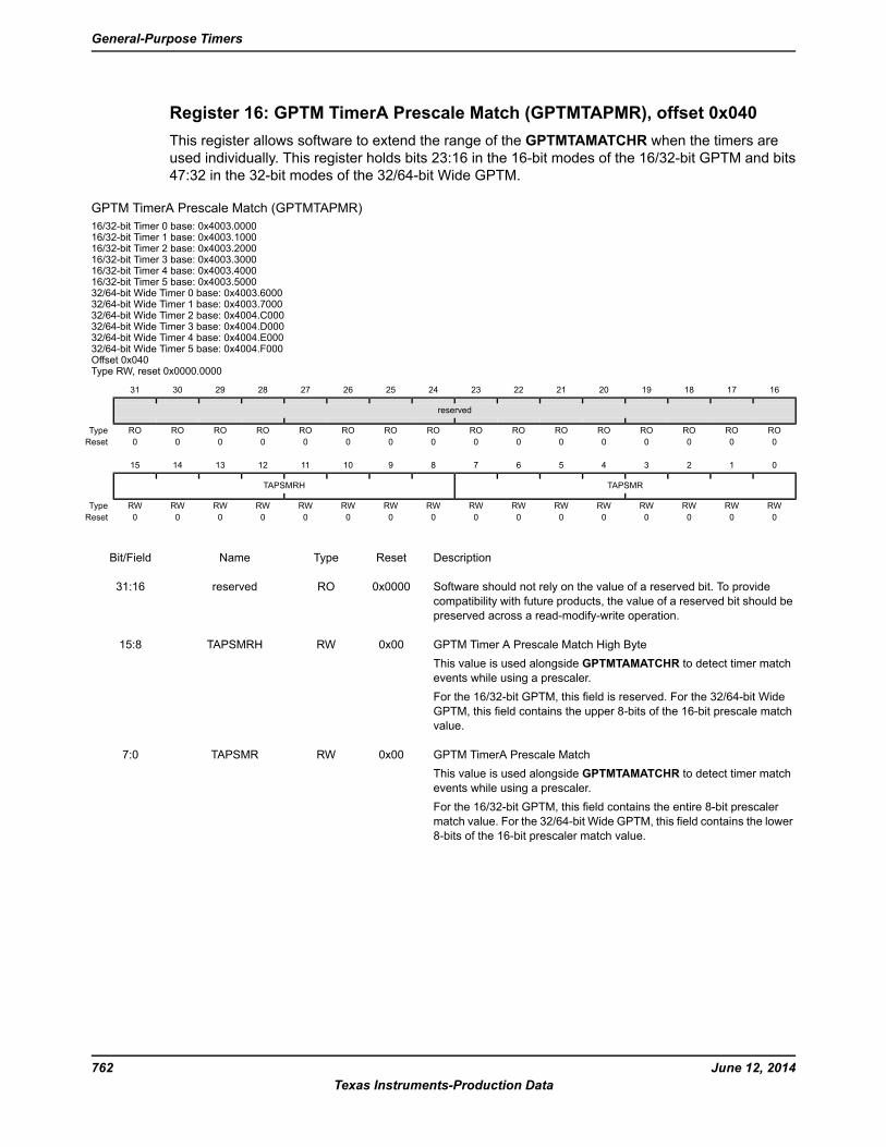
Register 16: GPTM TimerA Prescale Match (GPTMTAPMR), offset 0x040
This register allows software to extend the range of the GPTMTAMATCHR when the timers are
used individually. This register holds bits 23:16 in the 16-bit modes of the 16/32-bit GPTM and bits
47:32 in the 32-bit modes of the 32/64-bit Wide GPTM.
GPTM TimerA Prescale Match (GPTMTAPMR)
16/32-bit Timer 0 base: 0x4003.000016/32-bit Timer 1 base: 0x4003.100016/32-bit Timer 2 base: 0x4003.200016/32-bit Timer 3 base: 0x4003.300016/32-bit Timer 4 base: 0x4003.400016/32-bit Timer 5 base: 0x4003.500032/64-bit Wide Timer 0 base: 0x4003.600032/64-bit Wide Timer 1 base: 0x4003.700032/64-bit Wide Timer 2 base: 0x4004.C00032/64-bit Wide Timer 3 base: 0x4004.D00032/64-bit Wide Timer 4 base: 0x4004.E00032/64-bit Wide Timer 5 base: 0x4004.F000Offset 0x040Type RW, reset 0x0000.0000
16171819202122232425262728293031
reserved
ROROROROROROROROROROROROROROROROType
0000000000000000Reset
0123456789101112131415
TAPSMRTAPSMRH
RWRWRWRWRWRWRWRWRWRWRWRWRWRWRWRWType
0000000000000000Reset
DescriptionResetTypeNameBit/Field
Software should not rely on the value of a reserved bit. To provide
compatibility with future products, the value of a reserved bit should be
preserved across a read-modify-write operation.
0x0000ROreserved31:16
GPTM Timer A Prescale Match High Byte
This value is used alongside GPTMTAMATCHR to detect timer match
events while using a prescaler.
For the 16/32-bit GPTM, this field is reserved. For the 32/64-bit Wide
GPTM, this field contains the upper 8-bits of the 16-bit prescale match
value.
0x00RWTAPSMRH15:8
GPTM TimerA Prescale Match
This value is used alongside GPTMTAMATCHR to detect timer match
events while using a prescaler.
For the 16/32-bit GPTM, this field contains the entire 8-bit prescaler
match value. For the 32/64-bit Wide GPTM, this field contains the lower
8-bits of the 16-bit prescaler match value.
0x00RWTAPSMR7:0
June 12, 2014762
Texas Instruments-Production Data
General-Purpose Timers

Register 17: GPTM TimerB Prescale Match (GPTMTBPMR), offset 0x044
This register allows software to extend the range of the GPTMTBMATCHR when the timers are
used individually. This register holds bits 23:16 in the 16-bit modes of the 16/32-bit GPTM and bits
47:32 in the 32-bit modes of the 32/64-bit Wide GPTM.
GPTM TimerB Prescale Match (GPTMTBPMR)
16/32-bit Timer 0 base: 0x4003.000016/32-bit Timer 1 base: 0x4003.100016/32-bit Timer 2 base: 0x4003.200016/32-bit Timer 3 base: 0x4003.300016/32-bit Timer 4 base: 0x4003.400016/32-bit Timer 5 base: 0x4003.500032/64-bit Wide Timer 0 base: 0x4003.600032/64-bit Wide Timer 1 base: 0x4003.700032/64-bit Wide Timer 2 base: 0x4004.C00032/64-bit Wide Timer 3 base: 0x4004.D00032/64-bit Wide Timer 4 base: 0x4004.E00032/64-bit Wide Timer 5 base: 0x4004.F000Offset 0x044Type RW, reset 0x0000.0000
16171819202122232425262728293031
reserved
ROROROROROROROROROROROROROROROROType
0000000000000000Reset
0123456789101112131415
TBPSMRTBPSMRH
RWRWRWRWRWRWRWRWRWRWRWRWRWRWRWRWType
0000000000000000Reset
DescriptionResetTypeNameBit/Field
Software should not rely on the value of a reserved bit. To provide
compatibility with future products, the value of a reserved bit should be
preserved across a read-modify-write operation.
0x0000ROreserved31:16
GPTM Timer B Prescale Match High Byte
This value is used alongside GPTMTBMATCHR to detect timer match
events while using a prescaler.
For the 16/32-bit GPTM, this field is reserved. For the 32/64-bit Wide
GPTM, this field contains the upper 8-bits of the 16-bit prescale match
value.
0x00RWTBPSMRH15:8
GPTM TimerB Prescale Match
This value is used alongside GPTMTBMATCHR to detect timer match
events while using a prescaler.
For the 16/32-bit GPTM, this field contains the entire 8-bit prescaler
match value. For the 32/64-bit Wide GPTM, this field contains the lower
8-bits of the 16-bit prescaler match value.
0x00RWTBPSMR7:0
763June 12, 2014
Texas Instruments-Production Data
Tiva™ TM4C123GH6PM Microcontroller
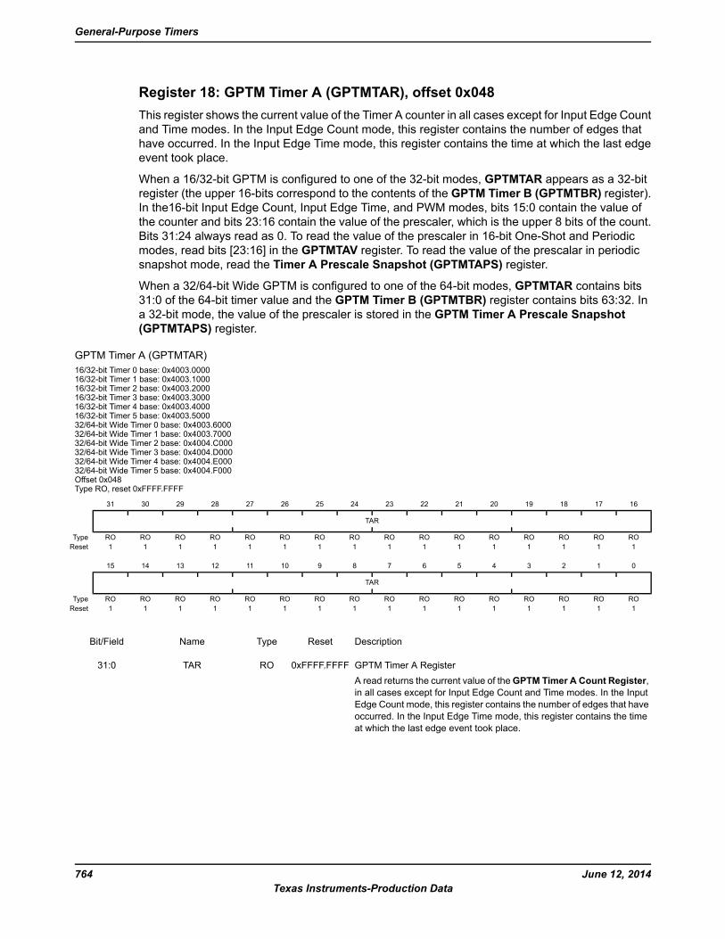
Register 18: GPTM Timer A (GPTMTAR), offset 0x048
This register shows the current value of the Timer A counter in all cases except for Input Edge Count
and Time modes. In the Input Edge Count mode, this register contains the number of edges that
have occurred. In the Input Edge Time mode, this register contains the time at which the last edge
event took place.
When a 16/32-bit GPTM is configured to one of the 32-bit modes, GPTMTAR appears as a 32-bit
register (the upper 16-bits correspond to the contents of the GPTM Timer B (GPTMTBR) register).
In the16-bit Input Edge Count, Input Edge Time, and PWM modes, bits 15:0 contain the value of
the counter and bits 23:16 contain the value of the prescaler, which is the upper 8 bits of the count.
Bits 31:24 always read as 0. To read the value of the prescaler in 16-bit One-Shot and Periodic
modes, read bits [23:16] in the GPTMTAV register. To read the value of the prescalar in periodic
snapshot mode, read the Timer A Prescale Snapshot (GPTMTAPS) register.
When a 32/64-bit Wide GPTM is configured to one of the 64-bit modes, GPTMTAR contains bits
31:0 of the 64-bit timer value and the GPTM Timer B (GPTMTBR) register contains bits 63:32. In
a 32-bit mode, the value of the prescaler is stored in the GPTM Timer A Prescale Snapshot
(GPTMTAPS) register.
GPTM Timer A (GPTMTAR)
16/32-bit Timer 0 base: 0x4003.000016/32-bit Timer 1 base: 0x4003.100016/32-bit Timer 2 base: 0x4003.200016/32-bit Timer 3 base: 0x4003.300016/32-bit Timer 4 base: 0x4003.400016/32-bit Timer 5 base: 0x4003.500032/64-bit Wide Timer 0 base: 0x4003.600032/64-bit Wide Timer 1 base: 0x4003.700032/64-bit Wide Timer 2 base: 0x4004.C00032/64-bit Wide Timer 3 base: 0x4004.D00032/64-bit Wide Timer 4 base: 0x4004.E00032/64-bit Wide Timer 5 base: 0x4004.F000Offset 0x048Type RO, reset 0xFFFF.FFFF
16171819202122232425262728293031
TAR
ROROROROROROROROROROROROROROROROType
1111111111111111Reset
0123456789101112131415
TAR
ROROROROROROROROROROROROROROROROType
1111111111111111Reset
DescriptionResetTypeNameBit/Field
GPTM Timer A Register
A read returns the current value of theGPTM Timer A Count Register,
in all cases except for Input Edge Count and Time modes. In the Input
Edge Count mode, this register contains the number of edges that have
occurred. In the Input Edge Time mode, this register contains the time
at which the last edge event took place.
0xFFFF.FFFFROTAR31:0
June 12, 2014764
Texas Instruments-Production Data
General-Purpose Timers
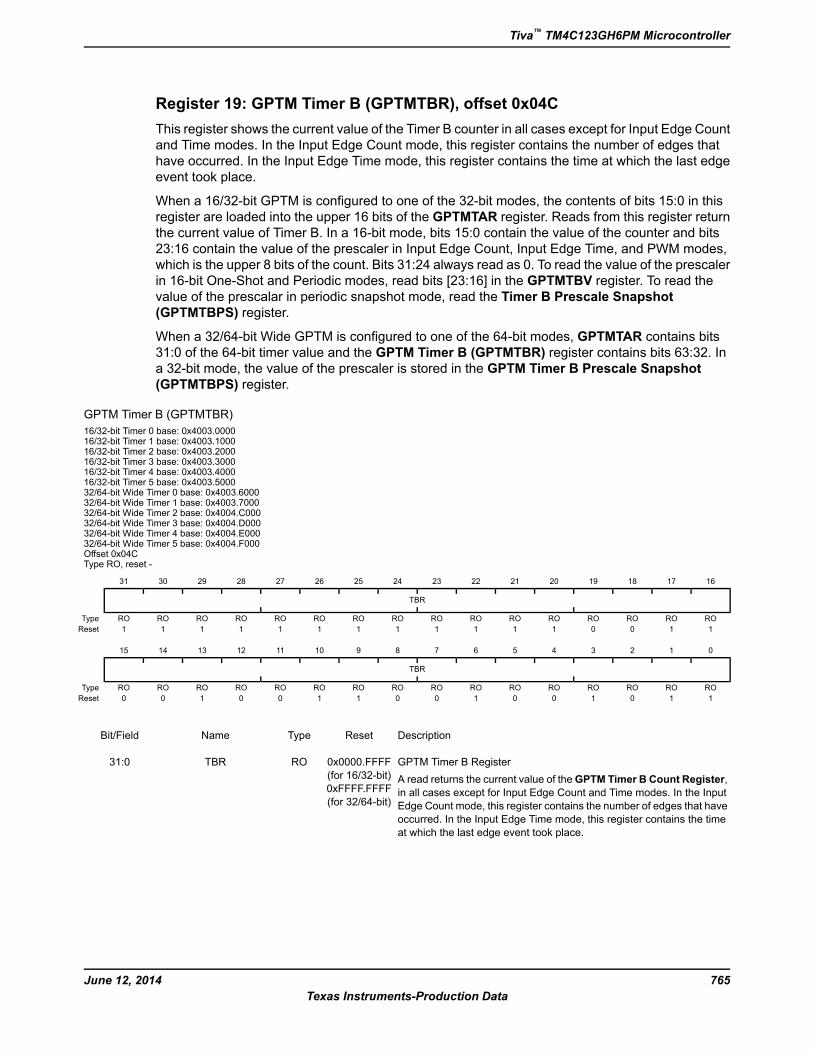
Register 19: GPTM Timer B (GPTMTBR), offset 0x04C
This register shows the current value of the Timer B counter in all cases except for Input Edge Count
and Time modes. In the Input Edge Count mode, this register contains the number of edges that
have occurred. In the Input Edge Time mode, this register contains the time at which the last edge
event took place.
When a 16/32-bit GPTM is configured to one of the 32-bit modes, the contents of bits 15:0 in this
register are loaded into the upper 16 bits of the GPTMTAR register. Reads from this register return
the current value of Timer B. In a 16-bit mode, bits 15:0 contain the value of the counter and bits
23:16 contain the value of the prescaler in Input Edge Count, Input Edge Time, and PWM modes,
which is the upper 8 bits of the count. Bits 31:24 always read as 0. To read the value of the prescaler
in 16-bit One-Shot and Periodic modes, read bits [23:16] in the GPTMTBV register. To read the
value of the prescalar in periodic snapshot mode, read the Timer B Prescale Snapshot
(GPTMTBPS) register.
When a 32/64-bit Wide GPTM is configured to one of the 64-bit modes, GPTMTAR contains bits
31:0 of the 64-bit timer value and the GPTM Timer B (GPTMTBR) register contains bits 63:32. In
a 32-bit mode, the value of the prescaler is stored in the GPTM Timer B Prescale Snapshot
(GPTMTBPS) register.
GPTM Timer B (GPTMTBR)
16/32-bit Timer 0 base: 0x4003.000016/32-bit Timer 1 base: 0x4003.100016/32-bit Timer 2 base: 0x4003.200016/32-bit Timer 3 base: 0x4003.300016/32-bit Timer 4 base: 0x4003.400016/32-bit Timer 5 base: 0x4003.500032/64-bit Wide Timer 0 base: 0x4003.600032/64-bit Wide Timer 1 base: 0x4003.700032/64-bit Wide Timer 2 base: 0x4004.C00032/64-bit Wide Timer 3 base: 0x4004.D00032/64-bit Wide Timer 4 base: 0x4004.E00032/64-bit Wide Timer 5 base: 0x4004.F000Offset 0x04CType RO, reset -
16171819202122232425262728293031
TBR
ROROROROROROROROROROROROROROROROType
1100111111111111Reset
0123456789101112131415
TBR
ROROROROROROROROROROROROROROROROType
1101001001100100Reset
DescriptionResetTypeNameBit/Field
GPTM Timer B Register
A read returns the current value of theGPTM Timer B Count Register,
in all cases except for Input Edge Count and Time modes. In the Input
Edge Count mode, this register contains the number of edges that have
occurred. In the Input Edge Time mode, this register contains the time
at which the last edge event took place.
0x0000.FFFF
(for 16/32-bit)
0xFFFF.FFFF
(for 32/64-bit)
ROTBR31:0
765June 12, 2014
Texas Instruments-Production Data
Tiva™ TM4C123GH6PM Microcontroller
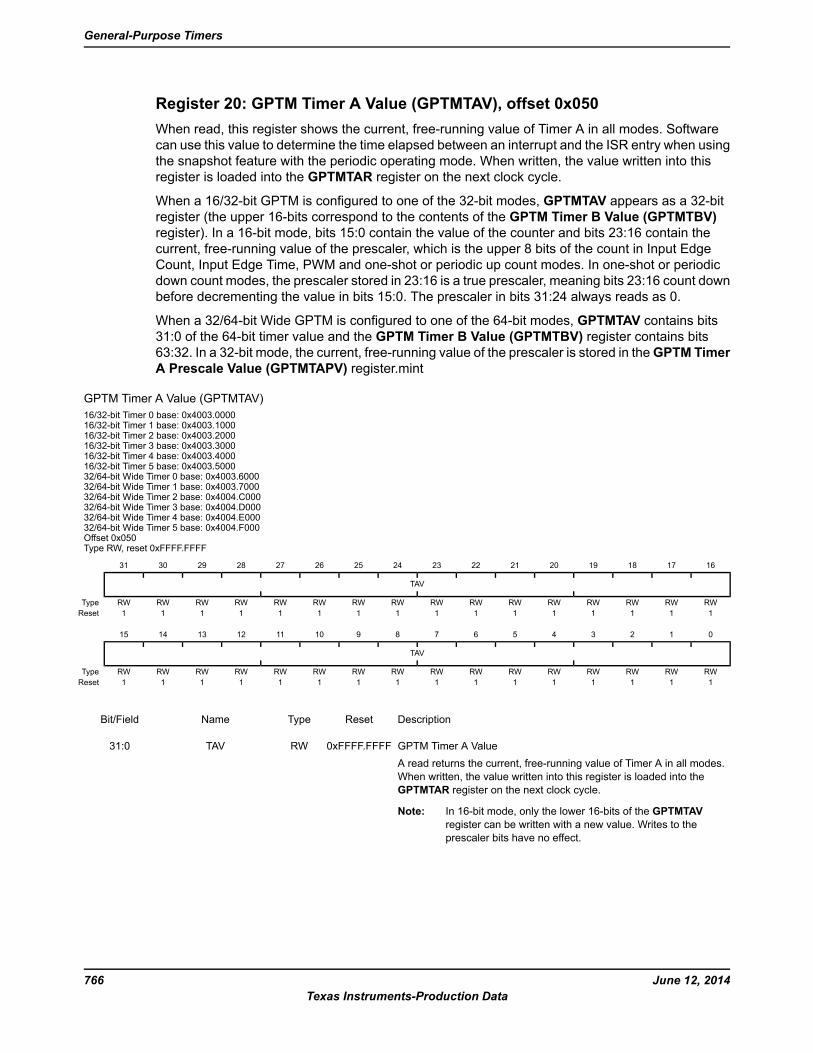
Register 20: GPTM Timer A Value (GPTMTAV), offset 0x050
When read, this register shows the current, free-running value of Timer A in all modes. Software
can use this value to determine the time elapsed between an interrupt and the ISR entry when using
the snapshot feature with the periodic operating mode. When written, the value written into this
register is loaded into the GPTMTAR register on the next clock cycle.
When a 16/32-bit GPTM is configured to one of the 32-bit modes, GPTMTAV appears as a 32-bit
register (the upper 16-bits correspond to the contents of the GPTM Timer B Value (GPTMTBV)
register). In a 16-bit mode, bits 15:0 contain the value of the counter and bits 23:16 contain the
current, free-running value of the prescaler, which is the upper 8 bits of the count in Input Edge
Count, Input Edge Time, PWM and one-shot or periodic up count modes. In one-shot or periodic
down count modes, the prescaler stored in 23:16 is a true prescaler, meaning bits 23:16 count down
before decrementing the value in bits 15:0. The prescaler in bits 31:24 always reads as 0.
When a 32/64-bit Wide GPTM is configured to one of the 64-bit modes, GPTMTAV contains bits
31:0 of the 64-bit timer value and the GPTM Timer B Value (GPTMTBV) register contains bits
63:32. In a 32-bit mode, the current, free-running value of the prescaler is stored in theGPTM Timer
A Prescale Value (GPTMTAPV) register.mint
GPTM Timer A Value (GPTMTAV)
16/32-bit Timer 0 base: 0x4003.000016/32-bit Timer 1 base: 0x4003.100016/32-bit Timer 2 base: 0x4003.200016/32-bit Timer 3 base: 0x4003.300016/32-bit Timer 4 base: 0x4003.400016/32-bit Timer 5 base: 0x4003.500032/64-bit Wide Timer 0 base: 0x4003.600032/64-bit Wide Timer 1 base: 0x4003.700032/64-bit Wide Timer 2 base: 0x4004.C00032/64-bit Wide Timer 3 base: 0x4004.D00032/64-bit Wide Timer 4 base: 0x4004.E00032/64-bit Wide Timer 5 base: 0x4004.F000Offset 0x050Type RW, reset 0xFFFF.FFFF
16171819202122232425262728293031
TAV
RWRWRWRWRWRWRWRWRWRWRWRWRWRWRWRWType
1111111111111111Reset
0123456789101112131415
TAV
RWRWRWRWRWRWRWRWRWRWRWRWRWRWRWRWType
1111111111111111Reset
DescriptionResetTypeNameBit/Field
GPTM Timer A Value
A read returns the current, free-running value of Timer A in all modes.
When written, the value written into this register is loaded into the
GPTMTAR register on the next clock cycle.
Note: In 16-bit mode, only the lower 16-bits of the GPTMTAV
register can be written with a new value. Writes to the
prescaler bits have no effect.
0xFFFF.FFFFRWTAV31:0
June 12, 2014766
Texas Instruments-Production Data
General-Purpose Timers
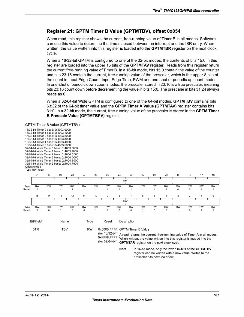
Register 21: GPTM Timer B Value (GPTMTBV), offset 0x054
When read, this register shows the current, free-running value of Timer B in all modes. Software
can use this value to determine the time elapsed between an interrupt and the ISR entry. When
written, the value written into this register is loaded into the GPTMTBR register on the next clock
cycle.
When a 16/32-bit GPTM is configured to one of the 32-bit modes, the contents of bits 15:0 in this
register are loaded into the upper 16 bits of the GPTMTAV register. Reads from this register return
the current free-running value of Timer B. In a 16-bit mode, bits 15:0 contain the value of the counter
and bits 23:16 contain the current, free-running value of the prescaler, which is the upper 8 bits of
the count in Input Edge Count, Input Edge Time, PWM and one-shot or periodic up count modes.
In one-shot or periodic down count modes, the prescaler stored in 23:16 is a true prescaler, meaning
bits 23:16 count down before decrementing the value in bits 15:0. The prescaler in bits 31:24 always
reads as 0.
When a 32/64-bit Wide GPTM is configured to one of the 64-bit modes, GPTMTBV contains bits
63:32 of the 64-bit timer value and the GPTM Timer A Value (GPTMTAV) register contains bits
31:0. In a 32-bit mode, the current, free-running value of the prescaler is stored in the GPTM Timer
B Prescale Value (GPTMTBPV) register.
GPTM Timer B Value (GPTMTBV)
16/32-bit Timer 0 base: 0x4003.000016/32-bit Timer 1 base: 0x4003.100016/32-bit Timer 2 base: 0x4003.200016/32-bit Timer 3 base: 0x4003.300016/32-bit Timer 4 base: 0x4003.400016/32-bit Timer 5 base: 0x4003.500032/64-bit Wide Timer 0 base: 0x4003.600032/64-bit Wide Timer 1 base: 0x4003.700032/64-bit Wide Timer 2 base: 0x4004.C00032/64-bit Wide Timer 3 base: 0x4004.D00032/64-bit Wide Timer 4 base: 0x4004.E00032/64-bit Wide Timer 5 base: 0x4004.F000Offset 0x054Type RW, reset -
16171819202122232425262728293031
TBV
RWRWRWRWRWRWRWRWRWRWRWRWRWRWRWRWType
1100111111111111Reset
0123456789101112131415
TBV
RWRWRWRWRWRWRWRWRWRWRWRWRWRWRWRWType
1101001001100100Reset
DescriptionResetTypeNameBit/Field
GPTM Timer B Value
A read returns the current, free-running value of Timer A in all modes.
When written, the value written into this register is loaded into the
GPTMTAR register on the next clock cycle.
Note: In 16-bit mode, only the lower 16-bits of the GPTMTBV
register can be written with a new value. Writes to the
prescaler bits have no effect.
0x0000.FFFF
(for 16/32-bit)
0xFFFF.FFFF
(for 32/64-bit)
RWTBV31:0
767June 12, 2014
Texas Instruments-Production Data
Tiva™ TM4C123GH6PM Microcontroller
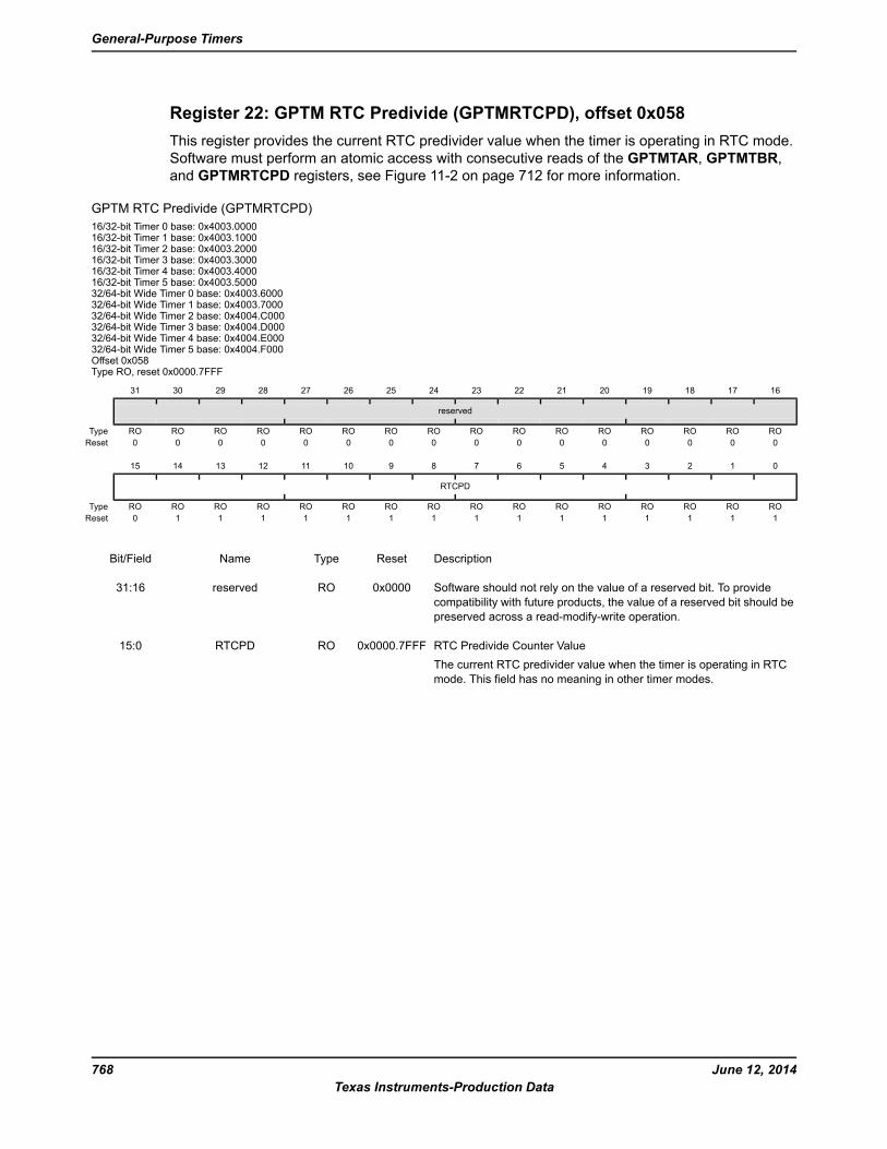
Register 22: GPTM RTC Predivide (GPTMRTCPD), offset 0x058
This register provides the current RTC predivider value when the timer is operating in RTC mode.
Software must perform an atomic access with consecutive reads of the GPTMTAR, GPTMTBR,
and GPTMRTCPD registers, see Figure 11-2 on page 712 for more information.
GPTM RTC Predivide (GPTMRTCPD)
16/32-bit Timer 0 base: 0x4003.000016/32-bit Timer 1 base: 0x4003.100016/32-bit Timer 2 base: 0x4003.200016/32-bit Timer 3 base: 0x4003.300016/32-bit Timer 4 base: 0x4003.400016/32-bit Timer 5 base: 0x4003.500032/64-bit Wide Timer 0 base: 0x4003.600032/64-bit Wide Timer 1 base: 0x4003.700032/64-bit Wide Timer 2 base: 0x4004.C00032/64-bit Wide Timer 3 base: 0x4004.D00032/64-bit Wide Timer 4 base: 0x4004.E00032/64-bit Wide Timer 5 base: 0x4004.F000Offset 0x058Type RO, reset 0x0000.7FFF
16171819202122232425262728293031
reserved
ROROROROROROROROROROROROROROROROType
0000000000000000Reset
0123456789101112131415
RTCPD
ROROROROROROROROROROROROROROROROType
1111111111111110Reset
DescriptionResetTypeNameBit/Field
Software should not rely on the value of a reserved bit. To provide
compatibility with future products, the value of a reserved bit should be
preserved across a read-modify-write operation.
0x0000ROreserved31:16
RTC Predivide Counter Value
The current RTC predivider value when the timer is operating in RTC
mode. This field has no meaning in other timer modes.
0x0000.7FFFRORTCPD15:0
June 12, 2014768
Texas Instruments-Production Data
General-Purpose Timers
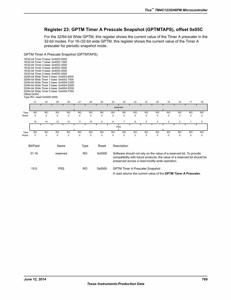
Register 23: GPTM Timer A Prescale Snapshot (GPTMTAPS), offset 0x05C
For the 32/64-bit Wide GPTM, this register shows the current value of the Timer A prescaler in the
32-bit modes. For 16-/32-bit wide GPTM, this register shows the current value of the Timer A
prescaler for periodic snapshot mode.
GPTM Timer A Prescale Snapshot (GPTMTAPS)
16/32-bit Timer 0 base: 0x4003.000016/32-bit Timer 1 base: 0x4003.100016/32-bit Timer 2 base: 0x4003.200016/32-bit Timer 3 base: 0x4003.300016/32-bit Timer 4 base: 0x4003.400016/32-bit Timer 5 base: 0x4003.500032/64-bit Wide Timer 0 base: 0x4003.600032/64-bit Wide Timer 1 base: 0x4003.700032/64-bit Wide Timer 2 base: 0x4004.C00032/64-bit Wide Timer 3 base: 0x4004.D00032/64-bit Wide Timer 4 base: 0x4004.E00032/64-bit Wide Timer 5 base: 0x4004.F000Offset 0x05CType RO, reset 0x0000.0000
16171819202122232425262728293031
reserved
ROROROROROROROROROROROROROROROROType
0000000000000000Reset
0123456789101112131415
PSS
ROROROROROROROROROROROROROROROROType
0000000000000000Reset
DescriptionResetTypeNameBit/Field
Software should not rely on the value of a reserved bit. To provide
compatibility with future products, the value of a reserved bit should be
preserved across a read-modify-write operation.
0x0000ROreserved31:16
GPTM Timer A Prescaler Snapshot
A read returns the current value of the GPTM Timer A Prescaler.
0x0000ROPSS15:0
769June 12, 2014
Texas Instruments-Production Data
Tiva™ TM4C123GH6PM Microcontroller
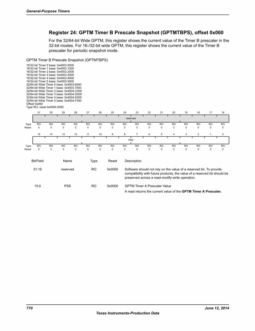
Register 24: GPTM Timer B Prescale Snapshot (GPTMTBPS), offset 0x060
For the 32/64-bit Wide GPTM, this register shows the current value of the Timer B prescaler in the
32-bit modes. For 16-/32-bit wide GPTM, this register shows the current value of the Timer B
prescaler for periodic snapshot mode.
GPTM Timer B Prescale Snapshot (GPTMTBPS)
16/32-bit Timer 0 base: 0x4003.000016/32-bit Timer 1 base: 0x4003.100016/32-bit Timer 2 base: 0x4003.200016/32-bit Timer 3 base: 0x4003.300016/32-bit Timer 4 base: 0x4003.400016/32-bit Timer 5 base: 0x4003.500032/64-bit Wide Timer 0 base: 0x4003.600032/64-bit Wide Timer 1 base: 0x4003.700032/64-bit Wide Timer 2 base: 0x4004.C00032/64-bit Wide Timer 3 base: 0x4004.D00032/64-bit Wide Timer 4 base: 0x4004.E00032/64-bit Wide Timer 5 base: 0x4004.F000Offset 0x060Type RO, reset 0x0000.0000
16171819202122232425262728293031
reserved
ROROROROROROROROROROROROROROROROType
0000000000000000Reset
0123456789101112131415
PSS
ROROROROROROROROROROROROROROROROType
0000000000000000Reset
DescriptionResetTypeNameBit/Field
Software should not rely on the value of a reserved bit. To provide
compatibility with future products, the value of a reserved bit should be
preserved across a read-modify-write operation.
0x0000ROreserved31:16
GPTM Timer A Prescaler Value
A read returns the current value of the GPTM Timer A Prescaler.
0x0000ROPSS15:0
June 12, 2014770
Texas Instruments-Production Data
General-Purpose Timers
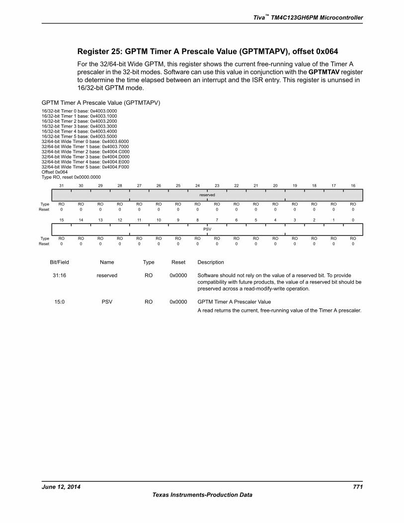
Register 25: GPTM Timer A Prescale Value (GPTMTAPV), offset 0x064
For the 32/64-bit Wide GPTM, this register shows the current free-running value of the Timer A
prescaler in the 32-bit modes. Software can use this value in conjunction with theGPTMTAV register
to determine the time elapsed between an interrupt and the ISR entry. This register is ununsed in
16/32-bit GPTM mode.
GPTM Timer A Prescale Value (GPTMTAPV)
16/32-bit Timer 0 base: 0x4003.000016/32-bit Timer 1 base: 0x4003.100016/32-bit Timer 2 base: 0x4003.200016/32-bit Timer 3 base: 0x4003.300016/32-bit Timer 4 base: 0x4003.400016/32-bit Timer 5 base: 0x4003.500032/64-bit Wide Timer 0 base: 0x4003.600032/64-bit Wide Timer 1 base: 0x4003.700032/64-bit Wide Timer 2 base: 0x4004.C00032/64-bit Wide Timer 3 base: 0x4004.D00032/64-bit Wide Timer 4 base: 0x4004.E00032/64-bit Wide Timer 5 base: 0x4004.F000Offset 0x064Type RO, reset 0x0000.0000
16171819202122232425262728293031
reserved
ROROROROROROROROROROROROROROROROType
0000000000000000Reset
0123456789101112131415
PSV
ROROROROROROROROROROROROROROROROType
0000000000000000Reset
DescriptionResetTypeNameBit/Field
Software should not rely on the value of a reserved bit. To provide
compatibility with future products, the value of a reserved bit should be
preserved across a read-modify-write operation.
0x0000ROreserved31:16
GPTM Timer A Prescaler Value
A read returns the current, free-running value of the Timer A prescaler.
0x0000ROPSV15:0
771June 12, 2014
Texas Instruments-Production Data
Tiva™ TM4C123GH6PM Microcontroller
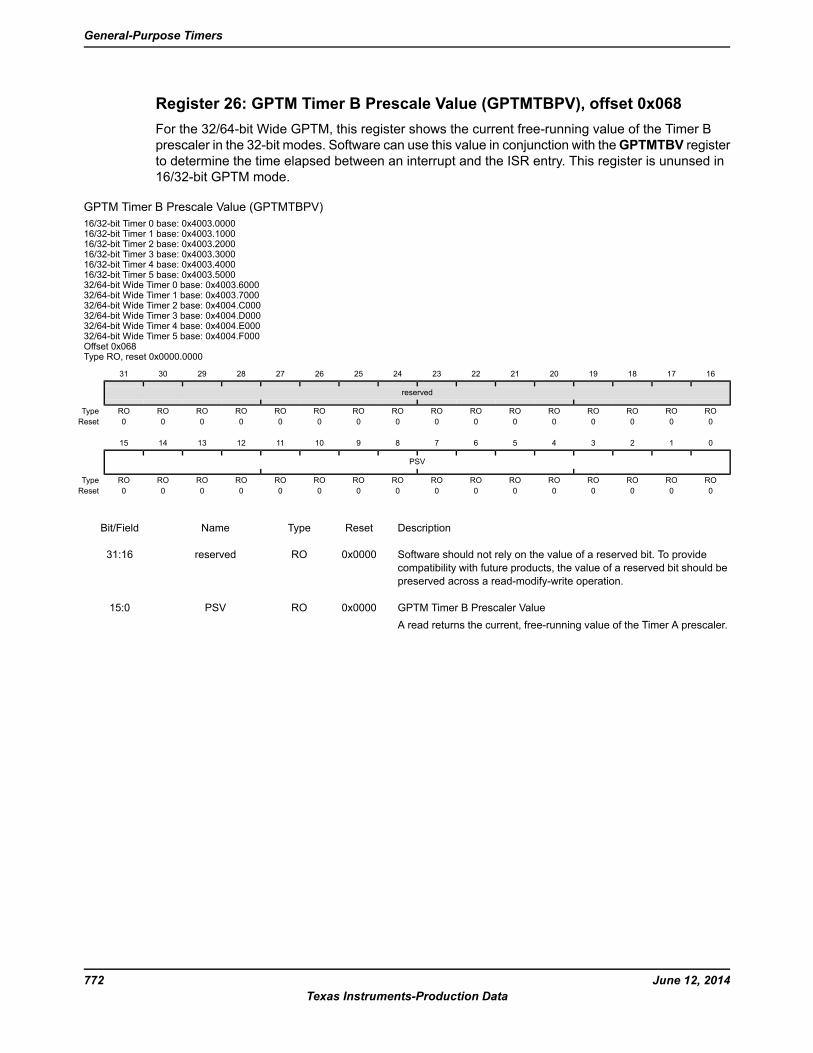
Register 26: GPTM Timer B Prescale Value (GPTMTBPV), offset 0x068
For the 32/64-bit Wide GPTM, this register shows the current free-running value of the Timer B
prescaler in the 32-bit modes. Software can use this value in conjunction with theGPTMTBV register
to determine the time elapsed between an interrupt and the ISR entry. This register is ununsed in
16/32-bit GPTM mode.
GPTM Timer B Prescale Value (GPTMTBPV)
16/32-bit Timer 0 base: 0x4003.000016/32-bit Timer 1 base: 0x4003.100016/32-bit Timer 2 base: 0x4003.200016/32-bit Timer 3 base: 0x4003.300016/32-bit Timer 4 base: 0x4003.400016/32-bit Timer 5 base: 0x4003.500032/64-bit Wide Timer 0 base: 0x4003.600032/64-bit Wide Timer 1 base: 0x4003.700032/64-bit Wide Timer 2 base: 0x4004.C00032/64-bit Wide Timer 3 base: 0x4004.D00032/64-bit Wide Timer 4 base: 0x4004.E00032/64-bit Wide Timer 5 base: 0x4004.F000Offset 0x068Type RO, reset 0x0000.0000
16171819202122232425262728293031
reserved
ROROROROROROROROROROROROROROROROType
0000000000000000Reset
0123456789101112131415
PSV
ROROROROROROROROROROROROROROROROType
0000000000000000Reset
DescriptionResetTypeNameBit/Field
Software should not rely on the value of a reserved bit. To provide
compatibility with future products, the value of a reserved bit should be
preserved across a read-modify-write operation.
0x0000ROreserved31:16
GPTM Timer B Prescaler Value
A read returns the current, free-running value of the Timer A prescaler.
0x0000ROPSV15:0
June 12, 2014772
Texas Instruments-Production Data
General-Purpose Timers

Register 27: GPTM Peripheral Properties (GPTMPP), offset 0xFC0
The GPTMPP register provides information regarding the properties of the General-Purpose Timer
module.
GPTM Peripheral Properties (GPTMPP)
16/32-bit Timer 0 base: 0x4003.000016/32-bit Timer 1 base: 0x4003.100016/32-bit Timer 2 base: 0x4003.200016/32-bit Timer 3 base: 0x4003.300016/32-bit Timer 4 base: 0x4003.400016/32-bit Timer 5 base: 0x4003.500032/64-bit Wide Timer 0 base: 0x4003.600032/64-bit Wide Timer 1 base: 0x4003.700032/64-bit Wide Timer 2 base: 0x4004.C00032/64-bit Wide Timer 3 base: 0x4004.D00032/64-bit Wide Timer 4 base: 0x4004.E00032/64-bit Wide Timer 5 base: 0x4004.F000Offset 0xFC0Type RO, reset 0x0000.0000
16171819202122232425262728293031
reserved
ROROROROROROROROROROROROROROROROType
0000000000000000Reset
0123456789101112131415
SIZEreserved
ROROROROROROROROROROROROROROROROType
0000000000000000Reset
DescriptionResetTypeNameBit/Field
Software should not rely on the value of a reserved bit. To provide
compatibility with future products, the value of a reserved bit should be
preserved across a read-modify-write operation.
0ROreserved31:4
Count Size
DescriptionValue
Timer A and Timer B counters are 16 bits each with an 8-bit
prescale counter.
0
Timer A and Timer B counters are 32 bits each with a 16-bit
prescale counter.
1
0x0ROSIZE3:0
773June 12, 2014
Texas Instruments-Production Data
Tiva™ TM4C123GH6PM Microcontroller