Embed Size (px)
Citation preview

TMI-2 ACCIDENT SCENARIO UPDATEa
E. L. Tolman, P. Kuan, J. M. BroughtonIdaho NationaT Engineering Laboratory
EG&G Idaho, Inc.Idaho Falls, Idaho 83415
ABSTRACT
Estimates of the end-state core configuration have been de-veloped from recent inspection of the lower regions of the1MM-2 core, core support assembly, and lower plenum regions.The inspection data have provided a basis for estimating theextent of damage to the core and core support structures andhave confirmed that the migration pathway of the molten corematerial to the lower plenum occurred in the east quadrant ofthe reactor vessel. This paper integrates the core inspectiondata with other TMI-2 data and supporting analysis to updatethe best-estimate core damage progression scenario.
INTRODUCTION
The TMI-2 Accident Evaluation Programl is being conducted by theDepartment of Energy (DOE) primarily to (a) develop an improved understand-ing of the physical mechanisms that controlled core damage progression dur-ing the accident and (b) utilize this improved understanding towardsresolving severe accident and source term issues for light water reactors.Reactor defueling work completed over the past two years has confirmed thatdamage to the THI core was extensive, with significant core material melt-ing and relocating to the lower plenum region of the reactor vessel. Asthey become available, the defueling data are being integrated with theinstrumentation data recorded during the accident and with independentsevere fuel damage experimental data to develop a best-estimate scenario ofthe TMI-2 core damage progression.
The previous scenario work2 was based on very limited knowledge ofthe damage in the lower half of the core, or confirmatory information rela-tive to the core failure mechanism and the core-to-lower plenum migrationpathways.
Recent inspections of the lower core, core support assembly (CSA), andlower plenum region3.4 are consistent with the initial core relocation
a. Work supported by the U.S. Department of Energy, Deputy AssistantSecretary for Reactor Deployment, Office of Nuclear Energy, under DOE Con-tract No. DE-AC07-76I001570.
39

mechanisms discussed in the previous accident scenario work. The inspec-tion data also provide additional information to improve understanding ofthe potential core failure mechanisms and the interaction of the moltencore materials with the core support structures and the lower reactor ves-sel head. This paper integrates the inspection data into the core damageprogression scenario during the first 4 h of the accident. Details of theaccident prior to 100 min will not be included, since coolant flow duringthis period prevented core heatup. References 5 and 6 provide a synopsisof the loss-of-coolant period of the accident between 0 and 100 min.
The accident progression after 100 min is divided into the followingthree time periods:
1. 100 to 174 mn--initial core heatup and degradation period.
2. 174 to 224 mmn--pump transient, initial emergency core coolingsystem (ECCS) injection, and continued degraded core heatup,
3. 224 to 230 min--core failure and relocation of molten core mate-rial into the lower plenum region.
Figure 1 shows the measured reactor system pressure and provides a time-line perspective of the accident during the first 4 h. Important mechan-isms controlling the core damage progression during each of these timeperiods are discussed with emphasis on the impact of the recent core in-spection data.
20
"a 150-
0
co
CO 100.
EC)0t
V) 5
0
B pumptransient
' HPIS on
--- F Block valve opened
A ~Coolant pumps|\
Block valve closed
I na. 1---- - I CoreInitial core Degraded relocation
I heatup core heatup
100 200
Time (minutes) P331 ST-0202-01
Figure 1. Measured reactor system pressure during the first 4 h hours ofthe TMI-2 accident, showing the major core damage progressiontime periods discussed in the paper.
40

INITIAL CORE HEATUP AND DEGRADATION (100 TO 174 MIN)
The important data sources relative to the Initial core heatup anddegradation include the following:
1. Hot leg superheat measured at 110 to 113 min indicates that coreuncovery occurred before this time; the response of the ex-coresource range monitor also suggests core uncovery as early as 110min.
2. Measured increases in containment radiation levels starting atapproximately 140 min indicates that a significant number of fuelrod failures (clad bursting) had occurred by this time.
3. Rapidly increasing primary system pressure after 150 min indi-cates that (a) a significant amount of hydrogen was present bythis time and was degrading heat transfer to the steam generat-ors, and/or (b) relocation of molten core material to the lowercore regions was increasing the steam generation rate.
4. Anomalous self-powered neutron detector (SPND) behavior startingat 150 min suggests that rapid core oxidation was occurring bythis time.
5. In-core instrument alarm data suggest no abnormal core behaviorat core elevations lower than approximately 30 in.
Core heatup predictions7 during this period are useful ining the above data. Figure 2 presents the calculated mid-core
interpret-temperature
4000
2
B 3000
0.
E
o 2000C
.0
EE 1000
0100 120 140 160 180 200
Time (min)220
P331 ST-0202-02
Figure 2. SCOAP predicted mid-core temperatures during initial core heatupperiod (100-174 min) for assumed lower and upper bounds and best-estimate cases of core liquid level.
41
responses for assumed bounding and best-estimate cases of core liquid lev-el. The lower-bound core heatup case assumes the core liquid levels fromearly NSAC analyses.8 The upper-bound core heatup case assumes no cool-ant addition to the reactor vessel after 100 min. The best-estimate caseuses the NSAC-predicted core liquid levels shifted in time by about 10 min,resulting in earlier core uncovery and calculated core temperatures moreconsistent with the above data sources.
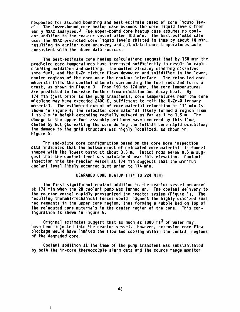
The best-estimate core heatup calculations suggest that by 150 min thepredicted core temperatures have increased sufficiently to result in rapidcladding oxidation and melting. The molten zircaloy cladding dissolvessome fuel, and the U-Zr mixture flows downward and solidifies in the lower,cooler regions of the core near the coolant interface. The relocated corematerial fills the coolant channels surrounding the fuel rods and forms acrust, as shown in Figure 3. From 150 to 174 min, the core temperaturesare predicted to increase further from oxidation and decay heat. By174 min (just prior to the pump transient), core temperatures near the coremidplane may have exceeded 2400 K, sufficient to melt the U-Zr-O ternarymaterial. The estimated extent of core material relocation at 174 min isshown in Figure 4; the relocated core material likely formed a region from1 to 2 m in height extending radially outward as far as 1 to 1.5 m. Thedamage to the upper fuel assembly grid may have occurred by this time,caused by hot gas exiting the core during the initial core rapid oxidation;the damage to the grid structure was highly localized, as shown inFigure 5.
The end-state core configuration based on the core bore inspectiondata indicates that the bottom crust of relocated core materials is funnelshaped with the lowest point at about 0.5 m. Intact rods below 0.5 m sug-gest that the coolant level was maintained near this elevation. Coolantinjection into the reactor vessel at 174 min suggests that the minimumcoolant level likely occurred just prior to 174 min.
DEGRADED CORE HEATUP (174 TO 224 MNI)
The first significant coolant addition to the reactor vessel occurredat 174 min when the 2B coolant pump was turned on. The coolant delivery tothe reactor vessel rapidly pressurized the reactor system (Figure 1). Theresulting thermal/mechanical forces would fragment the highly oxidized fuelrod remnants in the upper core region, thus forming a rubble bed on top ofthe relocated core materials in the center region of the core. This con-figuration is shown in Figure 6.
Original estimates suggest that as much as 1000 ft3 of water mayhave been injected into the reactor vessel. However, extensive core flowblockage would have limited the flow and cooling within the central regionsof the degraded core.
Coolant addition at the time of the pump transient was substantiatedby both the in-core thermocouple alarm data and the source range monitor
42

Transition Zone- rodsHigh temperatureremnants at top; High temperamolten cladding r Mfdand U02 around pellets an Irods at bottom. pellesaddingMelt has traveled cadnthrough this zone- Solidifiled cruremoving spacer 00near liquid legrids and attacking
~65361
Figure 3. Estimated core configuration at 150 nun showing the initialrelocation of core materials
43

grid
-High temperatureremnants ofU02 pelletsand ZrO2cladding
-Partially moltenZrO2 1UO2
-SolidifiedZrO2 1UO 2betweenfuel rods'Approximateliquid waterlevelAnn 11 I II
6 5362
Figure 4. Estimated core configuration at 174 min, just prior to the pumptransient, showing extensive core material relocation.
44

B Loop
B Loop _-*Outlet
Figure 5.
©9
(a
0e
0
.,__A LoopOutlet
Damage zones to the lower surface of the upper fuel assemblygrid structure.
45

grid
-Possiblesmall void
-Fragmentedfuel rods
-Possible uppercrust
-PartiallymoltenZrO2 1UO 2betweenfuel rods
Approximateliquid waterlevel ~
ZrO2 1UO 2betweenfuel rods
It I I I I I
6 5315
Figure 6. Estimated core configuration at 175 to 180 min showing the upperrods fragmented, forming a debris bed.
46

response. Those core thermocouples that were cooled as a result of thepump transient are shown in Figure 7. Note that only those thermocouplesgenerally on the periphery of the degraded core were cooled. These datasuggest that formation of the degraded core and lower core crust occurredprior to 174 min, as depicted in Figures 3 through 5. Subsequent alarmdata show that all thermocouples cooled by the pump transient again alarmedoff-scale (heated up) prior to emergency core coolant injection at 200 min,indicating concurrent reduction in the reactor vessel liquid level duringthe 174- to 200-min time period.
3 Peripheral thermocouplescooled during pump transient
15 _Location of in-coreinstrument assemblies
L~J Contour for lower crust13 of molten core region
121 1
1 0
9
8
7
6
5
4
3
2
1
iA|B |C|D|E|F|G|H |K|L|M|N|O|P |R|P331 ST-0202-03
Figure 7. Overlayby the Imolten 2
ofpumpzone
the in-core thermocouple positions that were cooled1 transient and the end-state contour of the lowercrust.
At 200 min, the high-pressure injection system was turned on. Thecoolant injection is somewhat uncertain; however, the best estimate of theinjection rate and the water injected by the pump transient, if directedentirely into the reactor vessel, would have resulted in a covered coresometime between 200 and 220 min. Cooling of the upper debris bed may havebeen a long-term process, with water gradually penetrating the interior ofthe debris bed from the core periphery. The resultant steam and hydrogenwould rapidly flow from the core into the upper plenum and may have also
47

contributed to the observed damage to the underside of the upper fuelassembly grid. The debris bed cooling process may have mixed the debrisbed and resulted in some molten ceramic material from the top of the moltencore zone being mixed into the upper debris bed. Examination of the uppercore debris particles indicate some molten material on selected particles.
The source range monitor response is also consistent with coolantaddition and subsequent boiloff, although the relative effects of coolantlevel and core reconfiguration tend to confound estimates of the liquidlevels. Neutronic analyses are currently underway to study the relativeeffect of core configuration versus liquid level.
Calculations9 to estimate the thermal response of the degraded TMI-2core configuration generally represented in Figures 4 and 5 indicate thatthe central core regions will continue to heat up independently of anycooling at the surface of the degraded core region, as shown in Figure 8.
3000
2500
v- 2000
a)M
Eg 1500
1000
5000.5 1 1.5 2 2.5
Height i)P331 ST-0202-04
Figure 8. Estimated degraded core thermal response from 175 to 225 min.
48

Notice that during the 174- to 224-min time period the center regions ofthe degraded core material are predicted to reach temperatures above 2500 K.
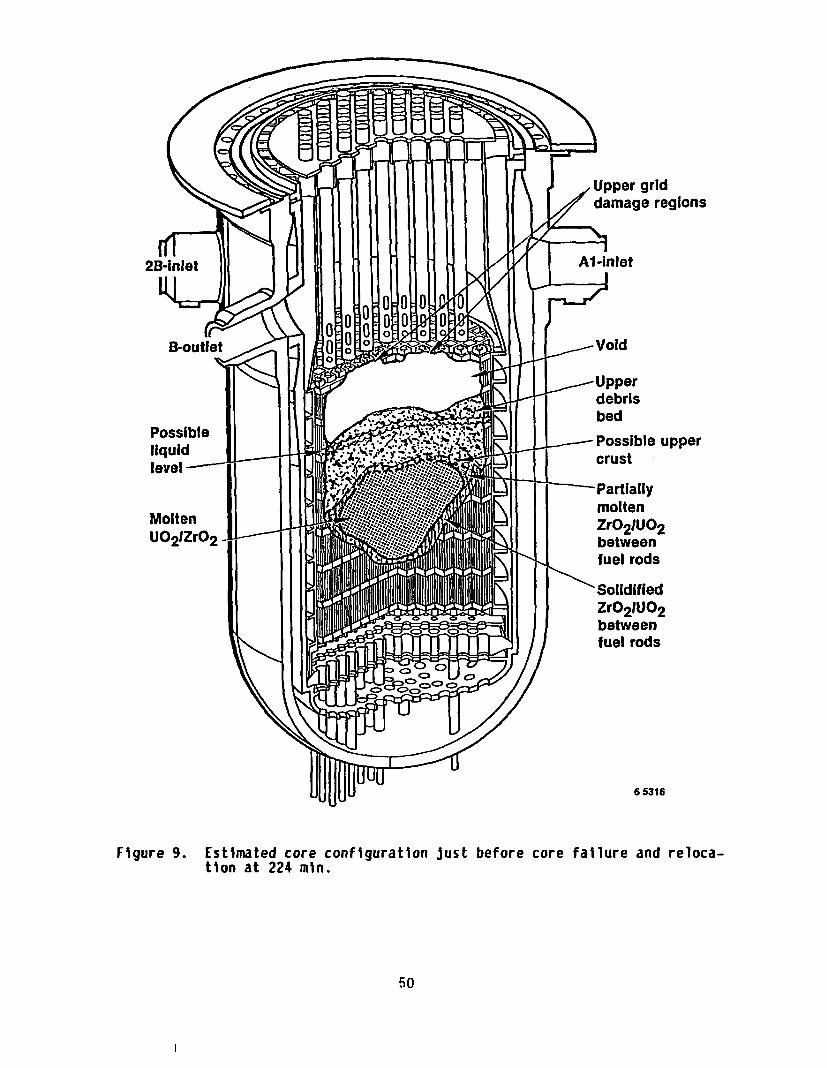
Thus, the estimated core configuration just prior to the core failureand migration of core material to the lower plenum at 224 min is shown inFigure 9. The central regions of the degraded core are predicted to bemolten. Cooling of the lower crust was maintained by water in the reactorvessel. However, the configuration and cooling of the upper crusts aremuch less understood due to (a) uncertainty in the growth rate of themolten zone, which is predominantly in the upward direction due to the con-vective heat transfer, and (b) uncertainty in the coolability of the upperdebris bed.
CORE FAILURE AND RELOCATION (224 TO 240 MIN)
At approximately 224 min, a global change in the core conditionoccurred as indicated by the in-core SPND and thermocouple alarm data, themeasured reactor system pressure and temperatures, and the source rangemonitors. The source range monitors, which directly measure changes incore configuration, increased significantly in less than 1 min and thendecayed normally, suggesting that the major relocation occurred in lessthan 1 min. The measured cold leg temperatures also increased rapidly(less than 10 s). The in-core SPNDs located in the bottom 30 in. of thecore alarmed off-scale for the first time during the accident. For many ofthe in-core instrument assemblies (particularly near the core center), off-scale alarms were recorded at all SPND axial elevations.
The core bore inspection data summarized in the previous paper pro-vides information for estimating the location of core failure and the flowpath of molten material to the lower plenum. The end-state core configura-tion cross sections as described in the previous paper suggest that failureof the core support crusts likely occurred, at least initially, in thesoutheast quadrant of the core. Figure 10 shows the core cross sectionsthrough the Row 6 fuel assemblies. At the core periphery in fuel assem-blies 0, P and R, the upper crust of the molten core zone is below the pro-jected bottom crust (based on the core bore contour data). This apparentdiscrepancy was also observed in the core cross section through the P rowof fuel assemblies and can be explained by localized failure of the corecrusts in these regions.
The, core bore inspection data also showed that significant moltenmaterial in the core support assembly regions was limited to only the eastquadrant of the reactor vessel, consistent with the inferred core failurelocations shown in Figure 10.
Another key observation consistent with localized core failure in theeast/southeast quadrant is the relative timing of the SPND alarms. At224 min, close examination of the in-core instrument alarm data shows thatthose SPNDs in the east quadrant alarmed first, followed by SPNDs locatednear the core center.
49
grid;e regions
ble upper
Figure 9. Estimated core configuration just before core failure and reloca-tion at 224 min.
50

.140
*r 130UG10
°O 110a-0 10
9-90inE" 800U,. 70
o 60
5 50
0 40-D.03
c 0- 20
I 10
0A B C D E F G H K L M N O P R
Fuel rod ossembly columnP331 ST-0202-O5
Figure 10. End-state core cross section (through the Row 6 fuel assem-blies) showing inconsistency in the upper and lower surfaces ofthe molten core zone (failure location) near the core peripheryin the east quadrant.

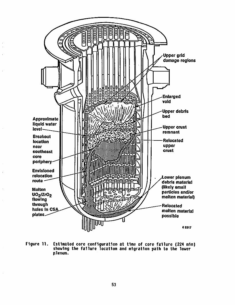
Thus, at 224 min, failure of the supporting core crusts occurred, fol-lowed by a rapid fuel migration into the lower plenum region as depicted inFigure 11. Several core failure mechanisms have been hypothesized. Theseinclude (a) melting of the upper crust as the degraded core materials con-tinue to heatup, (b) mechanical stress on the crust due to pressure differ-ences between the molten interior and exterior of the degraded core region,and (c) possible interactions between the degraded core materials and thecore former wall at the core periphery. Further cdre characterization andsupporting analysis work will be required to converge on a best-estimatecore failure mechanism. This work will be essential to complete our under-standing of the extent of damage to the CSA and lower vessel head and in-strument tube penetrations.
SUMMARY AND CONCLUSIONS
The TMI-2 Accident Evaluation Program is providing a more completeunderstanding of the core damage progression through characterization ofthe degraded reactor core and supporting analysis to interpret the data.Important conclusions from this work include:
1. The accident scenario provides a generally consistent interpreta-tion of the TMI-2 end-state characterization data and on-linemeasurements.
2. The core failure location appears to be at the periphery of themolten zone, near the top. More examination of the core failureregion and supporting analysis work will be required to moreclearly identify the most likely core failure mechanism.
3. The bottom core crust was stable as a result of water in thereactor vessel.
More work will be necessary to characterize and evaluate the damage tothe lower core and CSA migration pathways and the damage to the lower ves-sel head and instrument tube penetrations. Improvements to the accidentscenario will be made as the core is defueled and examinations completed onthe core, CSA, and lower plenum debris samples.
REFERENCES
1. E. Tolman et.al, TMI-2 Accident Evaluation Program, EGG-TMI-7048,February 1986.
2. J. Broughton, 'Core Condition and Accident Scenario", Proceedings ofthe First International Information Meeting on the TMI-2 Accident.Conf-8510166, October 1985.
52
grid
170, g\./, V,. I) L
level-s..
Breakoutlocationnearsoutheastcore
-Relocateduppercrust
routeEl I I I I I I I I I I I
,Lower plenumdebris material(likely smallparticles andlormolten material)
Molten- CZP U C�>C:o �C>
"O'-Relocatedmolten materialpossible
6 5317
Figure 11. Estimated core configuration at time of core failure (224 min)showing the failure location and migration path to the lowerplenum.
53
3. R. McCardell et.al, 'Results of the TMI-2 Core Bores,. Paper Presentedat the 14th-NRC Light Water Reactor Safety Meeting. Gaithersburg.Maryland, October 1986.
4. E. Tolman, et.al, TMI-2 Core Bore Acquisition Summary Report,EGG-TMI-7385, September 1986.
5. Analysis of Three Mile Island-Unit 2 Accident, NSAC-80-l (NSAC-1Revised), Nuclear Safety Analysis Center (NSAC), Electric PowerResearch Institute (EPRI), Palo Alto, CA, March 1980.
6. G. Thomas, 'Description of the TMI-2 Accident', American ChemicalSociety Svmposium Series No. 293. Three Mile Island Accident:Diagnosis and Prognosis, May 1985.
7. C. Allison et.al, SCDAP/MODl Analysis of the Progression of CoreDamage During the TMI-2 Accident, SE-CMD-84-006, July 1984.
8. K. Adron, D. Cain, THI Accident Core Heatup Analysis, NSAC-24, January1981.
9. P. Kuan, TMI-2 Core Debris Bed Coolability, EGG-TMI-7150, March 1986.
54