Embed Size (px)
Citation preview
Materials’ Supply &DeliveryofLeone ACP Waterline Replacement Project 1
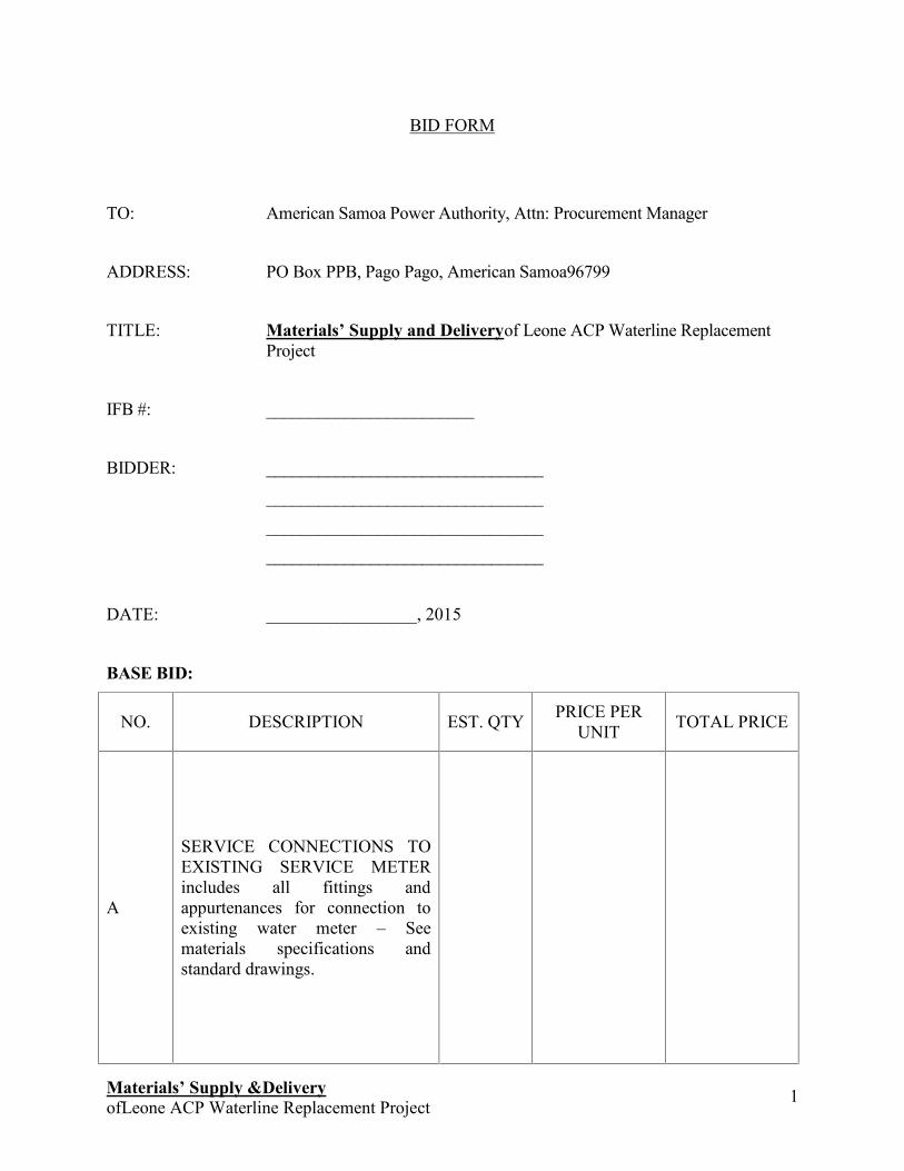
BID FORM
TO: American Samoa Power Authority, Attn: Procurement Manager
ADDRESS: PO Box PPB, Pago Pago, American Samoa96799
TITLE: Materials’ Supply and Deliveryof Leone ACP Waterline ReplacementProject
IFB #: ________________________
BIDDER: ________________________________
________________________________
________________________________
________________________________
DATE: _________________, 2015
BASE BID:
NO. DESCRIPTION EST. QTY PRICE PERUNIT TOTAL PRICE
A
SERVICE CONNECTIONS TOEXISTING SERVICE METERincludes all fittings andappurtenances for connection toexisting water meter – Seematerials specifications andstandard drawings.
Materials’ Supply &DeliveryofLeone ACP Waterline Replacement Project 2
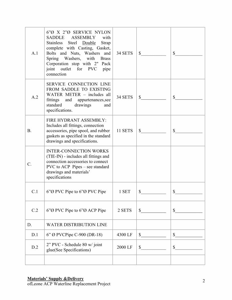
A.1
6ӯ X 2ӯ SERVICE NYLONSADDLE ASSEMBLY withStainless Steel Double Strapcomplete with Casting, Gasket,Bolts and Nuts, Washers andSpring Washers, with BrassCorporation stop with 2" Packjoint outlet for PVC pipeconnection
34 SETS $___________ $____________
A.2
SERVICE CONNECTION LINEFROM SADDLE TO EXISTINGWATER METER – includes allfittings and appurtenances,seestandard drawings andspecifications.
34 SETS $___________ $____________
B.
FIRE HYDRANT ASSEMBLY:Includes all fittings, connectionaccessories, pipe spool, and rubbergaskets as specified in the standarddrawings and specifications.
11 SETS $___________ $____________
C.
INTER-CONNECTION WORKS(TIE-IN) - includes all fittings andconnection accessories to connectPVC to ACP Pipes – see standarddrawings and materials’specifications
C.1 6ӯ PVC Pipe to 6ӯ PVC Pipe 1 SET $___________ $____________
C.2 6ӯ PVC Pipe to 6ӯ ACP Pipe 2 SETS $___________ $____________
D. WATER DISTRIBUTION LINE
D.1 6” Ø PVCPipe C-900 (DR-18) 4300 LF $___________ $____________
D.2 2” PVC - Schedule 80 w/ jointglue(See Specifications) 2000 LF $___________ $____________
Materials’ Supply &DeliveryofLeone ACP Waterline Replacement Project 3
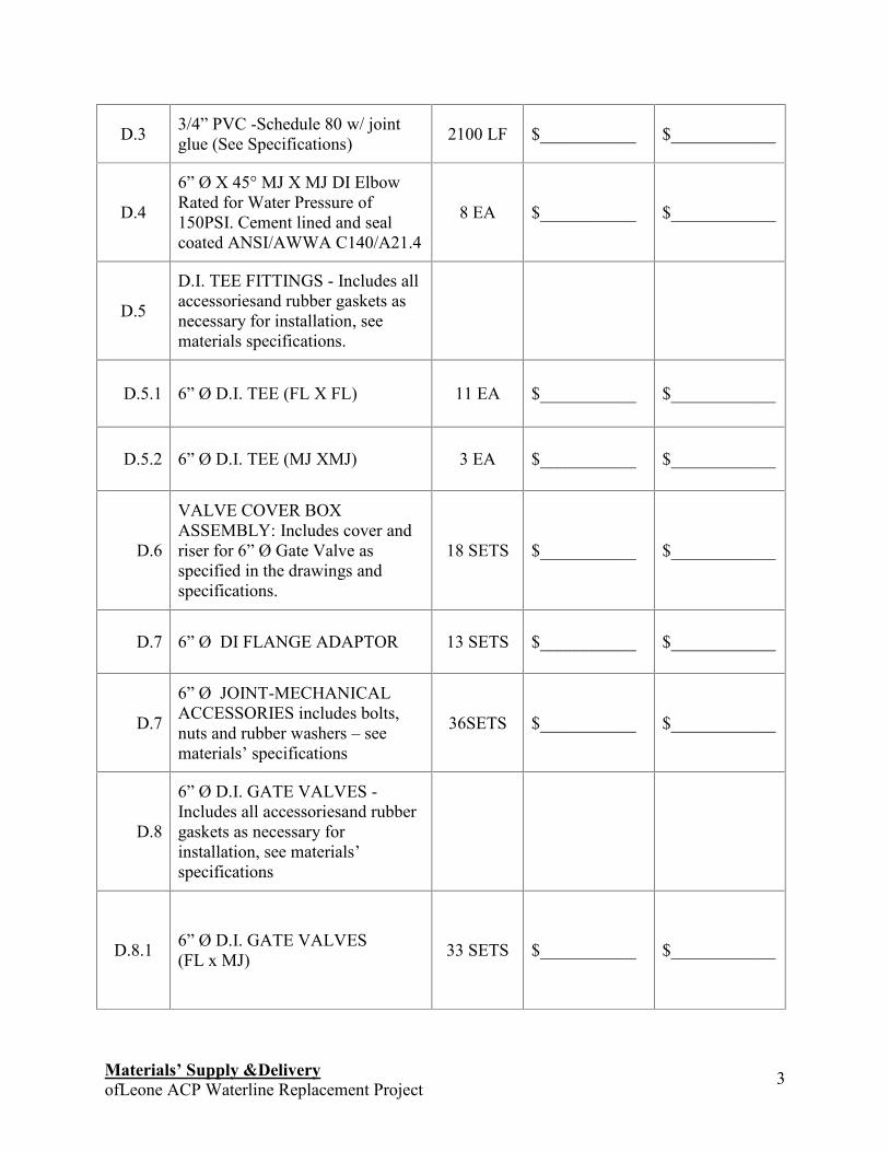
D.3 3/4” PVC -Schedule 80 w/ jointglue (See Specifications) 2100 LF $___________ $____________
D.4
6” Ø X 45° MJ X MJ DI ElbowRated for Water Pressure of150PSI. Cement lined and sealcoated ANSI/AWWA C140/A21.4
8 EA $___________ $____________
D.5
D.I. TEE FITTINGS - Includes allaccessoriesand rubber gaskets asnecessary for installation, seematerials specifications.
D.5.1 6” Ø D.I. TEE (FL X FL) 11 EA $___________ $____________
D.5.2 6” Ø D.I. TEE (MJ XMJ) 3 EA $___________ $____________
D.6
VALVE COVER BOXASSEMBLY: Includes cover andriser for 6” Ø Gate Valve asspecified in the drawings andspecifications.
18 SETS $___________ $____________
D.7 6” Ø DI FLANGE ADAPTOR 13 SETS $___________ $____________
D.7
6” Ø JOINT-MECHANICALACCESSORIES includes bolts,nuts and rubber washers – seematerials’ specifications
36SETS $___________ $____________
D.8
6” Ø D.I. GATE VALVES -Includes all accessoriesand rubbergaskets as necessary forinstallation, see materials’specifications
D.8.1 6” Ø D.I. GATE VALVES(FL x MJ) 33 SETS $___________ $____________
Materials’ Supply &DeliveryofLeone ACP Waterline Replacement Project 4
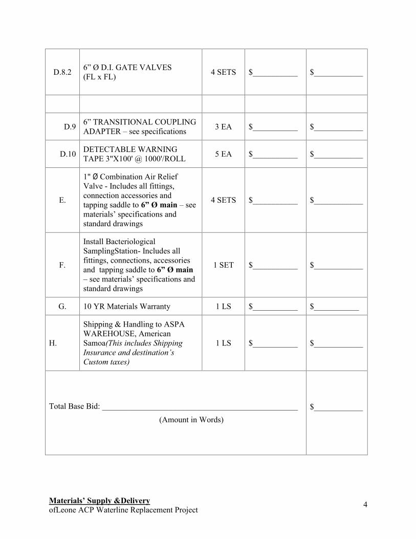
D.8.2 6” Ø D.I. GATE VALVES(FL x FL) 4 SETS $___________ $____________
D.9 6” TRANSITIONAL COUPLINGADAPTER – see specifications 3 EA $___________ $____________
D.10 DETECTABLE WARNINGTAPE 3"X100' @ 1000'/ROLL 5 EA $___________ $____________
E.
1" Ø Combination Air ReliefValve - Includes all fittings,connection accessories andtapping saddle to 6” Ø main – seematerials’ specifications andstandard drawings
4 SETS $___________ $____________
F.
Install BacteriologicalSamplingStation- Includes allfittings, connections, accessoriesand tapping saddle to 6” Ø main– see materials’ specifications andstandard drawings
1 SET $___________ $____________
G. 10 YR Materials Warranty 1 LS $___________ $___________
H.
Shipping & Handling to ASPAWAREHOUSE, AmericanSamoa(This includes ShippingInsurance and destination’sCustom taxes)
1 LS $___________ $____________
Total Base Bid: ________________________________________________
(Amount in Words)$____________
Materials’ Supply &DeliveryofLeone ACP Waterline Replacement Project 5
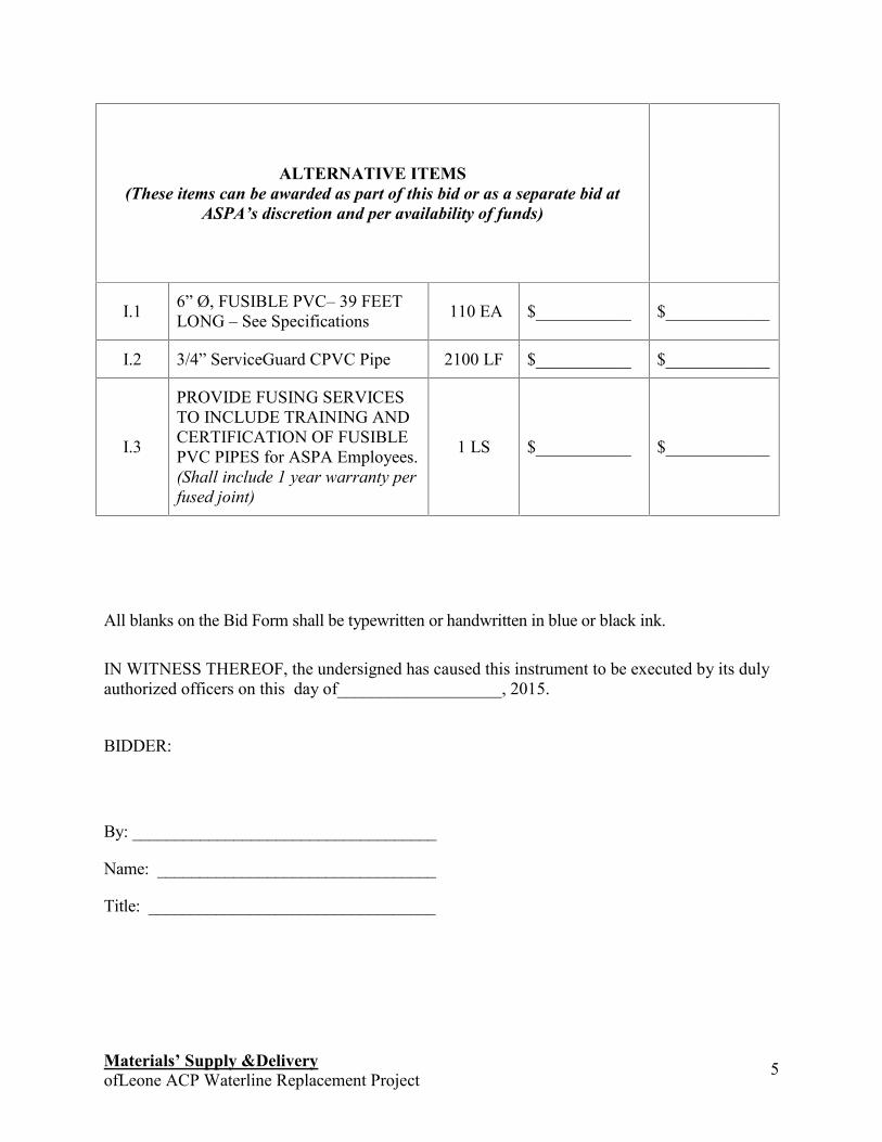
ALTERNATIVE ITEMS(These items can be awarded as part of this bid or as a separate bid at
ASPA’s discretion and per availability of funds)
I.1 6” Ø, FUSIBLE PVC– 39 FEETLONG – See Specifications 110 EA $___________ $____________
I.2 3/4” ServiceGuard CPVC Pipe 2100 LF $___________ $____________
I.3
PROVIDE FUSING SERVICESTO INCLUDE TRAINING ANDCERTIFICATION OF FUSIBLEPVC PIPES for ASPA Employees.(Shall include 1 year warranty perfused joint)
1 LS $___________ $____________
All blanks on the Bid Form shall be typewritten or handwritten in blue or black ink.
IN WITNESS THEREOF, the undersigned has caused this instrument to be executed by its dulyauthorized officers on this day of___________________, 2015.
BIDDER:
By: ____________________________________
Name: _________________________________
Title: __________________________________
Materials Supply & Delivery ofLEONE PIPELINE REPLACEMENT PROJECT 1
American Samoa Power Authority
Engineering Services DivisionWater Department
Leone Materials Supply and DeliveryTechnical Specifications
Jan 2015
_________________________UTU ABE MALAE
Executive Director
Materials Supply & Delivery ofLEONE PIPELINE REPLACEMENT PROJECT 1
American Samoa Power Authority
Engineering Services DivisionWater Department
Leone Materials Supply and DeliveryTechnical Specifications
Jan 2015
_________________________UTU ABE MALAE
Executive Director
Materials Supply & Delivery ofLEONE PIPELINE REPLACEMENT PROJECT 1
American Samoa Power Authority
Engineering Services DivisionWater Department
Leone Materials Supply and DeliveryTechnical Specifications
Jan 2015
_________________________UTU ABE MALAE
Executive Director
Materials Supply & Delivery ofLEONE PIPELINE REPLACEMENT PROJECT 2
ContentsFUSIBLE POLYVINYL CHLORIDE (PVC) WATER PIPE.................................................................................4
PART 1 - GENERAL ............................................................................................................................................4PART 2 - QUALITY ASSURANCE.......................................................................................................................4PART 3 - PRODUCTS .........................................................................................................................................9PART 4 - EXECUTION......................................................................................................................................12
END SECTION..........................................................................................................................................................14
WATER PIPE AND FITTINGS (DUCTILE/CAST IRON)..................................................................................14
PART 1 GENERAL...........................................................................................................................................141.1 SECTION DESCRIPTION........................................................................................................................141.2 REFERENCES..........................................................................................................................................141.3 PRODUCTS..............................................................................................................................................14
END SECTION..........................................................................................................................................................16
AIR RELEASE VALVE ASSEMBLY ....................................................................................................................16
PART 1 GENERAL...........................................................................................................................................161.1 SECTION DESCRIPTION........................................................................................................................161.2 REFERENCES..........................................................................................................................................171.3 GENERAL ................................................................................................................................................17
END SECTION..........................................................................................................................................................17
FIRE HYDRANT ......................................................................................................................................................17
PART 1 GENERAL...........................................................................................................................................171.1 SECTION DESCRIPTION........................................................................................................................171.2 REFERENCES..........................................................................................................................................181.3 GENERAL ................................................................................................................................................18
END SECTION..........................................................................................................................................................18
SERVICE SADDLE ..................................................................................................................................................18
PART 1 GENERAL...........................................................................................................................................181.1 SECTION DESCRIPTION........................................................................................................................191.2 MATERIALS & REFERENCES................................................................................................................191.3 SIZES:.......................................................................................................................................................191.4 GENERAL ................................................................................................................................................20
END SECTION..........................................................................................................................................................20
BACTERIOLOGICAL SAMPLING STATION....................................................................................................20
PART 1 GENERAL...........................................................................................................................................201.1 SECTION DESCRIPTION........................................................................................................................201.2 MATERIALS .............................................................................................................................................201.3 FINISH .....................................................................................................................................................211.4 DIMENSION: See drawings provided. ....................................................................................................211.5 GENERAL ................................................................................................................................................21
END SECTION..........................................................................................................................................................21
SERVICE CONNECTION ASSEMBLY ................................................................................................................21
PART 1 GENERAL...........................................................................................................................................211.1 SECTION DESCRIPTION........................................................................................................................211.2 MATERIALS & REFERENCES................................................................................................................21
Materials Supply & Delivery ofLEONE PIPELINE REPLACEMENT PROJECT 3
1.3 SIZES:.......................................................................................................................................................221.4 PRODUCT: ..............................................................................................................................................22
END SECTION..........................................................................................................................................................22
PVC SCHEDULE 80 PIPE .......................................................................................................................................22
PART 1 GENERAL...........................................................................................................................................221.1 SCOPE......................................................................................................................................................221.2 PIPE DESCRIPTION ...............................................................................................................................221.3 QUALITY ASSURANCE ...........................................................................................................................23
END SECTION..........................................................................................................................................................23
Materials Supply & Delivery ofLEONE PIPELINE REPLACEMENT PROJECT 4
FUSIBLE POLYVINYL CHLORIDE (PVC) WATER PIPE
PART 1 - GENERAL1.1 SCOPE OF WORK
1.1.1 This section specifies fusible polyvinyl chloride (PVC) pipe, including standardsfor dimensionality, testing, quality.
1.2 PIPE DESCRIPTION
1.2.1 Pipe supplier shall furnish fusible PVC pipe as manufactured by UndergroundSolutions, Inc. or approved equal conforming to all standards and procedures, andmeeting all testing and material properties as described in this specification.
PART 2 - QUALITY ASSURANCE
2.1 REFERANCES
2.1.1 ANSI/AWWA C110/A21.10 American National Standard forDuctile-Iron and Gray-Iron Fittings,3-inch through 48-inch, for Water andOther Liquids.
2.1.2 ANSI/AWWA C111/A21.11 American National Standard forRubber-Gasket Joints for Ductile-IronPressure Pipe and Fittings.
2.1.3 AWWA C605 Standard for Underground Installationof Polyvinyl Chloride (PVC) PressurePipe and Fittings for Water
2.1.4 AWWA C651 Standard for Disinfecting WaterMains
Materials Supply & Delivery ofLEONE PIPELINE REPLACEMENT PROJECT 5
2.1.5 AWWA C900 Standard for Polyvinyl Chloride(PVC) Pressure Pipe and FabricatedFittings, 4 in. through 12 in. (100mmThrough 300mm), for WaterDistribution.
2.1.6 AWWA C905 Standard for Polyvinyl Chloride (PVCPressure Pipe and Fabricated Fittings,14 in. through 48 in. (350mmThrough 1200mm), for WaterDistribution and Transmission.
2.1.7 AWWA M23 AWWA Manual of Supply Practices PVCPipe- Design and Installation, SecondEdition
2.1.8 ASTM C923 Standard Specification for ResilientConnectors between ReinforcedConcrete Manhole Structures, Pipesand Laterals
2.1.9 ASTM D1784 Rigid Polyvinyl Chloride (PVC)Compounds and ChlorinatedPolyvinyl Chloride (CPVC)Compounds
2.1.10 ASTM D1785 Polyvinyl Chloride (PVC) PlasticPipe, Schedules 40, 80, and 120
2.1.11 ASTM D2152 Test Method for Degree of Fusion ofExtruded Poly vinyl Chloride (PVC)Pipe and Molded Fittings by AcetoneImmersion
2.1.12 ASTM D2241 Polyvinyl Chloride (PVC) Plastic Pipe(SDR-PR)
Materials Supply & Delivery ofLEONE PIPELINE REPLACEMENT PROJECT 6
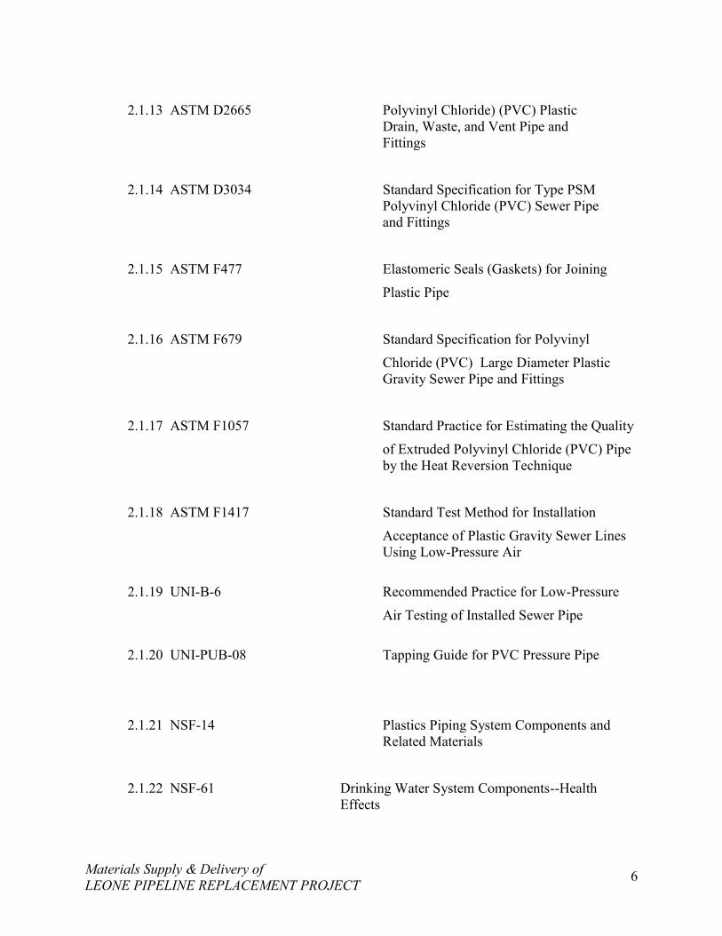
2.1.13 ASTM D2665 Polyvinyl Chloride) (PVC) PlasticDrain, Waste, and Vent Pipe andFittings
2.1.14 ASTM D3034 Standard Specification for Type PSMPolyvinyl Chloride (PVC) Sewer Pipeand Fittings
2.1.15 ASTM F477 Elastomeric Seals (Gaskets) for Joining
Plastic Pipe
2.1.16 ASTM F679 Standard Specification for Polyvinyl
Chloride (PVC) Large Diameter PlasticGravity Sewer Pipe and Fittings
2.1.17 ASTM F1057 Standard Practice for Estimating the Quality
of Extruded Polyvinyl Chloride (PVC) Pipeby the Heat Reversion Technique
2.1.18 ASTM F1417 Standard Test Method for Installation
Acceptance of Plastic Gravity Sewer LinesUsing Low-Pressure Air
2.1.19 UNI-B-6 Recommended Practice for Low-Pressure
Air Testing of Installed Sewer Pipe
2.1.20 UNI-PUB-08 Tapping Guide for PVC Pressure Pipe
2.1.21 NSF-14 Plastics Piping System Components andRelated Materials
2.1.22 NSF-61 Drinking Water System Components--HealthEffects
Materials Supply & Delivery ofLEONE PIPELINE REPLACEMENT PROJECT 7
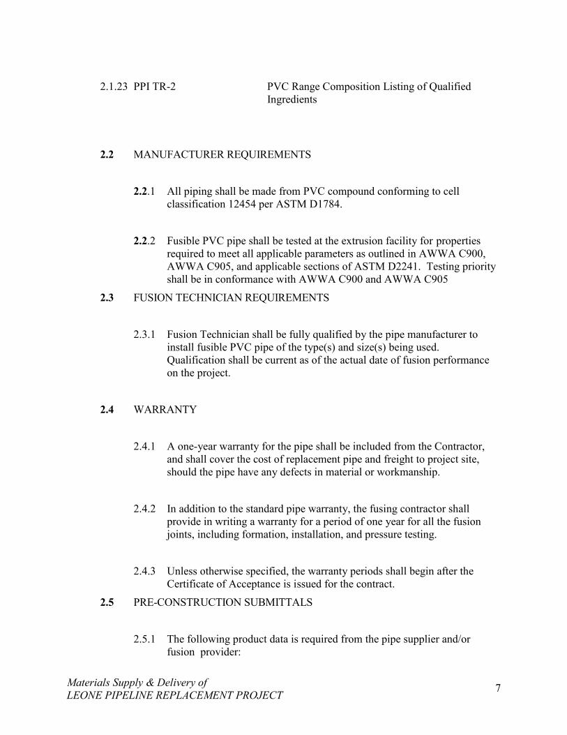
2.1.23 PPI TR-2 PVC Range Composition Listing of QualifiedIngredients
2.2 MANUFACTURER REQUIREMENTS
2.2.1 All piping shall be made from PVC compound conforming to cellclassification 12454 per ASTM D1784.
2.2.2 Fusible PVC pipe shall be tested at the extrusion facility for propertiesrequired to meet all applicable parameters as outlined in AWWA C900,AWWA C905, and applicable sections of ASTM D2241. Testing priorityshall be in conformance with AWWA C900 and AWWA C905
2.3 FUSION TECHNICIAN REQUIREMENTS
2.3.1 Fusion Technician shall be fully qualified by the pipe manufacturer toinstall fusible PVC pipe of the type(s) and size(s) being used.Qualification shall be current as of the actual date of fusion performanceon the project.
2.4 WARRANTY
2.4.1 A one-year warranty for the pipe shall be included from the Contractor,and shall cover the cost of replacement pipe and freight to project site,should the pipe have any defects in material or workmanship.
2.4.2 In addition to the standard pipe warranty, the fusing contractor shallprovide in writing a warranty for a period of one year for all the fusionjoints, including formation, installation, and pressure testing.
2.4.3 Unless otherwise specified, the warranty periods shall begin after theCertificate of Acceptance is issued for the contract.
2.5 PRE-CONSTRUCTION SUBMITTALS
2.5.1 The following product data is required from the pipe supplier and/orfusion provider:
Materials Supply & Delivery ofLEONE PIPELINE REPLACEMENT PROJECT 8
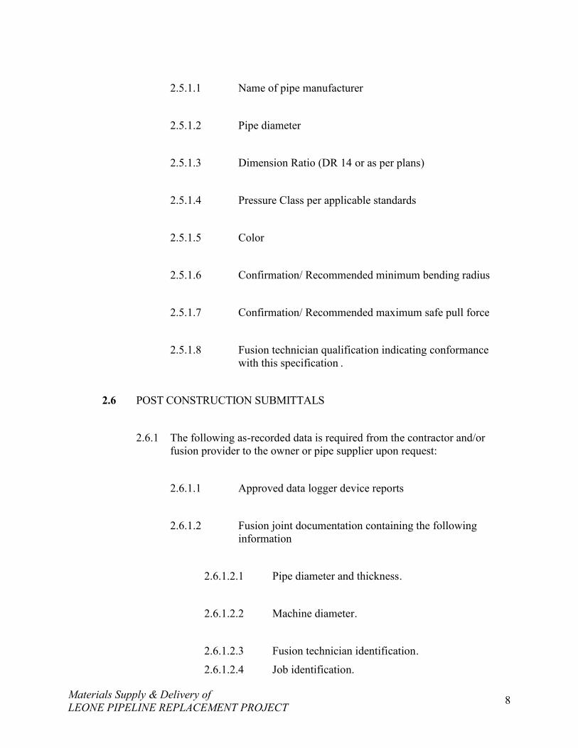
2.5.1.1 Name of pipe manufacturer
2.5.1.2 Pipe diameter
2.5.1.3 Dimension Ratio (DR 14 or as per plans)
2.5.1.4 Pressure Class per applicable standards
2.5.1.5 Color
2.5.1.6 Confirmation/ Recommended minimum bending radius
2.5.1.7 Confirmation/ Recommended maximum safe pull force
2.5.1.8 Fusion technician qualification indicating conformancewith this specification .
2.6 POST CONSTRUCTION SUBMITTALS
2.6.1 The following as-recorded data is required from the contractor and/orfusion provider to the owner or pipe supplier upon request:
2.6.1.1 Approved data logger device reports
2.6.1.2 Fusion joint documentation containing the followinginformation
2.6.1.2.1 Pipe diameter and thickness.
2.6.1.2.2 Machine diameter.
2.6.1.2.3 Fusion technician identification.
2.6.1.2.4 Job identification.
Materials Supply & Delivery ofLEONE PIPELINE REPLACEMENT PROJECT 9
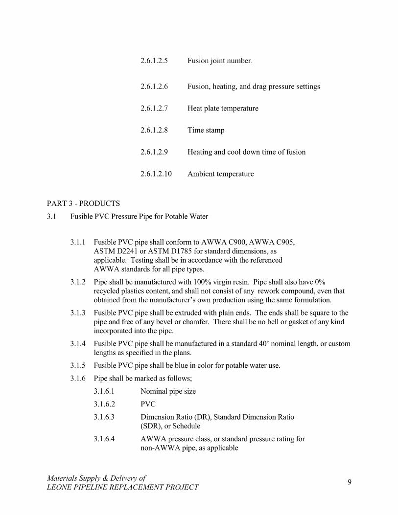
2.6.1.2.5 Fusion joint number.
2.6.1.2.6 Fusion, heating, and drag pressure settings
2.6.1.2.7 Heat plate temperature
2.6.1.2.8 Time stamp
2.6.1.2.9 Heating and cool down time of fusion
2.6.1.2.10 Ambient temperature
PART 3 - PRODUCTS
3.1 Fusible PVC Pressure Pipe for Potable Water
3.1.1 Fusible PVC pipe shall conform to AWWA C900, AWWA C905,ASTM D2241 or ASTM D1785 for standard dimensions, asapplicable. Testing shall be in accordance with the referencedAWWA standards for all pipe types.
3.1.2 Pipe shall be manufactured with 100% virgin resin. Pipe shall also have 0%recycled plastics content, and shall not consist of any rework compound, even thatobtained from the manufacturer’s own production using the same formulation.
3.1.3 Fusible PVC pipe shall be extruded with plain ends. The ends shall be square to thepipe and free of any bevel or chamfer. There shall be no bell or gasket of any kindincorporated into the pipe.
3.1.4 Fusible PVC pipe shall be manufactured in a standard 40’ nominal length, or customlengths as specified in the plans.
3.1.5 Fusible PVC pipe shall be blue in color for potable water use.
3.1.6 Pipe shall be marked as follows;
3.1.6.1 Nominal pipe size
3.1.6.2 PVC
3.1.6.3 Dimension Ratio (DR), Standard Dimension Ratio(SDR), or Schedule
3.1.6.4 AWWA pressure class, or standard pressure rating fornon-AWWA pipe, as applicable
Materials Supply & Delivery ofLEONE PIPELINE REPLACEMENT PROJECT 10
3.1.6.5 AWWA standard designation number, or pipe typefor non-AWWA pipe, as applicable
3.1.6.6 NSF-61 mark verifying suitability for potable waterservice
3.1.6.7 Extrusion production-record code
3.1.6.8 Trademark or trade name
3.1.6.9 Cell Classification 12454 and/or PVC material code1120 may also be included
3.1.6.10 Pipe shall be homogeneous throughout and be free ofvisible cracks, holes, foreign material, blisters, orother visible deleterious faults.
3.2 FUSION JOINTS
3.2.1 Unless otherwise specified, fusible PVC pipe lengths shall be assembledin the field with butt-fused joints. The Contractor shall follow the pipesupplier’s written guidelines for this procedure. All fusion joints shall becompleted as described in this specification.
3.3 CONNECTION AND FITTINGS
3.3.1 In Connection: Connections shall be defined in conjunction with thecoupling of project piping, as well as the tie-ins to other piping systems.
3.3.2 Ductile Iron Mechanical and Flanged Fittings: Acceptable fittings for usewith fusible PVC pipe shall include standard ductile iron fittingsconforming to AWWA/ANSI C110/A21.10, or AWWA/ANSIC153/A21.53 and AWWA/ANSI C111/A21.11.
3.3.2.1 Connections to fusible PVC pipe may be made using arestrained or non-restrained retainer gland product for PVCpipe, as well as for MJ or flanged fittings.
3.3.2.2 Bends, tees and other ductile iron fittings shall be restrainedwith the use of thrust blocking or other means as indicatedin the construction documents.
Materials Supply & Delivery ofLEONE PIPELINE REPLACEMENT PROJECT 11
3.3.2.3 Ductile iron fittings and glands must be installed per themanufacturer’s guidelines.
3.3.3 Sleeve-Type Couplings
3.3.3.1 Sleeve-type mechanical couplings shall be manufacturedfor use with PVC pressure pipe, and may be restrained orunrestrained as necessary.
3.3.3.2 Sleeve-type couplings shall be rated at the same or greaterpressure carrying capacity as the pipe itself.
3.3.4 Expansion and Flexible Couplings
3.3.4.1 Expansion-type mechanical couplings shall bemanufactured for use with PVC pipe, and may berestrained or unrestrained as necessary.
3.3.4.2 Expansion-type mechanical couplings shall be rated at thesame or greater pressure carrying capacity as the pipe itself.
3.3.5 Connection Hardware
3.3.5.1 Bolts and nuts for buried service shall be made of non-corrosive, high-strength, low-alloy steel having thecharacteristics specified in ANSI/AWWA C111/A21.11,regardless of any other protective coating
3.4 MAXIMUM ALLOWABLE PULL-IN FORCE
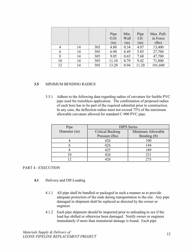
3.4.1 Adhere to the following data regarding maximum allowable pull-in forcefor fusible PVC pipe used for trenchless application. The confirmation ofproposed radius of each bore has to be part of the required submittal priorto construction.
PipeDiameter
(in)
DimensionRatio(DR)
Max.WorkingPressure
(psi)
DIPS Series
Materials Supply & Delivery ofLEONE PIPELINE REPLACEMENT PROJECT 12
PipeO.D.(in)
Min.Wall(in)
PipeI.D.(in)
Max. Pull-in Force
(Ibs)4 14 305 4.80 0.34 4.07 13,4006 14 305 6.90 0.49 5.85 27,7008 14 305 9.05 0.65 7.68 47,700
10 14 305 11.10 0.79 9.42 71,80012 14 305 13.20 0.94 11.20 101,600
3.5 MINIMUM BENDING RADIUS
3.5.1 Adhere to the following data regarding radius of curvature for fusible PVCpipe used for trenchless application. The confirmation of proposed radiusof each bore has to be part of the required submittal prior to construction.In any case, the deflection radius must not exceed 75% of the maximumallowable curvature allowed for standard C-900 PVC pipe.
PipeDiameter (in)
DIPS SeriesCritical Bucking
Pressure (Ibs)Minimum Allowable
Bending (ft)4 426 1006 426 1448 425 189
10 426 23112 426 275
PART 4 - EXECUTION
4.1 Delivery and Off-Loading
4.1.1 All pipe shall be bundled or packaged in such a manner as to provideadequate protection of the ends during transportation to the site. Any pipedamaged in shipment shall be replaced as directed by the owner orengineer.
4.1.2 Each pipe shipment should be inspected prior to unloading to see if theload has shifted or otherwise been damaged. Notify owner or engineerimmediately if more than immaterial damage is found. Each pipe
Materials Supply & Delivery ofLEONE PIPELINE REPLACEMENT PROJECT 13
shipment should be checked for quantity and proper pipe size, color, andtype.
4.1.3 Pipe should be loaded, off-loaded, and otherwise handled in accordancewith AWWA M23, and all of the pipe supplier’s guidelines shall befollowed.
4.1.4 Off-loading devices such as chains, wire rope, chokers, or other pipehandling implements that may scratch, nick, cut, or gouge the pipe arestrictly prohibited.
4.1.5 During removal and handling, be sure that the pipe does not strikeanything. Significant impact could cause damage, particularly during coldweather.
4.1.6 If appropriate unloading equipment is not available, pipe may be unloadedby removing individual pieces. Care should be taken to insure that pipe isnot dropped or damaged. Pipe should be carefully lowered, not dropped,from trucks.
4.2 Handling and Storage
4.2.1 Any length of pipe showing a crack or which has received a blow that mayhave caused an incident fracture, even though no such fracture can beseen, shall be marked as rejected and removed at once from the work.Damaged areas, or possible areas of damage may be removed by cuttingout and removing the suspected incident fracture area. Limits of theacceptable length of pipe shall be determined by the owner or engineer.
4.2.3 Any scratch or gouge greater than 10% of the wall thickness will beconsidered significant and can be rejected unless determined acceptable bythe owner or engineer.
4.2.4 Pipe lengths should be stored and placed on level ground. Pipe should bestored at the job site in the unit packaging provided by the manufacturer.Caution should be exercised to avoid compression, damage, ordeformation to the ends of the pipe. The interior of the pipe, as well as allend surfaces, should be kept free from dirt and foreign matter.
4.2.5 Pipe shall be handled and supported with the use of woven fiber pipeslings or approved equal. Care shall be exercised when handling the pipeto not cut, gouge, scratch or otherwise abrade the piping in any way.
Materials Supply & Delivery ofLEONE PIPELINE REPLACEMENT PROJECT 14
4.2.6 If pipe is to be stored for periods of 1 year or longer, the pipe should beshaded or otherwise shielded from direct sunlight. Covering of the pipewhich allows for temperature build-up is strictly prohibited. Pipe shouldbe covered with an opaque material while permitting adequate aircirculation above and around the pipe as required to prevent excess heataccumulation.
END SECTION
WATER PIPE AND FITTINGS (DUCTILE/CAST IRON)
PART 1 GENERAL
1.1 SECTION DESCRIPTION
1.1.1 This specification includes but is not limited to Ductile Iron Pipes, fittings,Valves, and appurtenances for the Water Storage Tank’s supply, distribution andoverflow lines.
1.2 REFERENCES
1.2.1 ANSI/AWWA C104/A21.4 – Cement-Mortar Lining for Ductile Iron Pipe andFittings for Water.
1.2.2 AWWA C105 – Polyethylene Encasement for Ductile-Iron Piping for Water andOther Liquids.
1.2.3 ANSI/AWWA C110/A21.10 – Ductile Iron and Gray Iron Fittings, 3 Inchthrough 48 Inch, for Water and Other Liquids.
1.2.4 ANSI/AWWA C111/A21.11 – Rubber-Gasket Joints for Ductile Iron and GrayIron Pressure Pipe and Fittings.
1.2.5 ANSI/AWWA C150/A21.50 – Thickness Design of Ductile Iron Pipe.
1.2.6 ANSI/AWWA C151/A21.51 – Ductile Iron Pipe, Centrifugally Cast, for Water orOther Liquids.
1.2.7 ANSI/AWWA C153/A21.53 – Ductile Iron Compact Fittings, 3 Inch through 16Inch, for Water and Other Liquids
1.3 PRODUCTS
Materials Supply & Delivery ofLEONE PIPELINE REPLACEMENT PROJECT 15
1.3.1 FABRICATED DUCTILE IRON PIPES FLG X FLG
1.3.1.1 AWWA C151, pressure class 350, centrifugally cast in metal molds orsand-lined molds, or C104, cement-mortar lining, as shown on thedrawings or bid schedule.
1.3.1.2 All Flanged Fabricated Pipe is Class 53 per AWWA C115 unlessotherwise noted.
1.3.1.3 GASKETS: AWWA C111 Standards specify the use of 1/8” FullFace rubber gaskets on all factory fabricated flanged ductile IronPipes. Please note that Gaskets must be cut to the “OLD STYLE”Dimensions.
1.3.2 JOINT THRUST RESTRAINT
1.3.2.1 Concrete Thrust Blocks: One part Portland cement, 2 ½ part of fineaggregate, 3 ½ parts coarse aggregate and just enough water for aworkable consistency using epoxy coated re bars.
1.3.2.2 Spatial Anchoring Retainer Glands for Mechanical Joints:
(a) EBAA Iron Series 2000PV
(b) ROMAC Industries Grip Ring
1.3.3 GATE VALVES
1.3.3.1 FOR UNDERGROUND INSTALLATION:
(a) Manufacturer: American Darling, Mueller, Clow orWaterous or equal
(b) Meet or exceed either AWWA C509 or C515,resilient seated gate valves 2 inch through 12 inchNPS, ductile iron body, trim, non-rising stem withsquare nut, single wedge, mechanical joint,flanged, or slip-on ends as specified in drawings,control rod, and extension box
(c) Furnish one valve key per contract or deliveryorder as applicable.
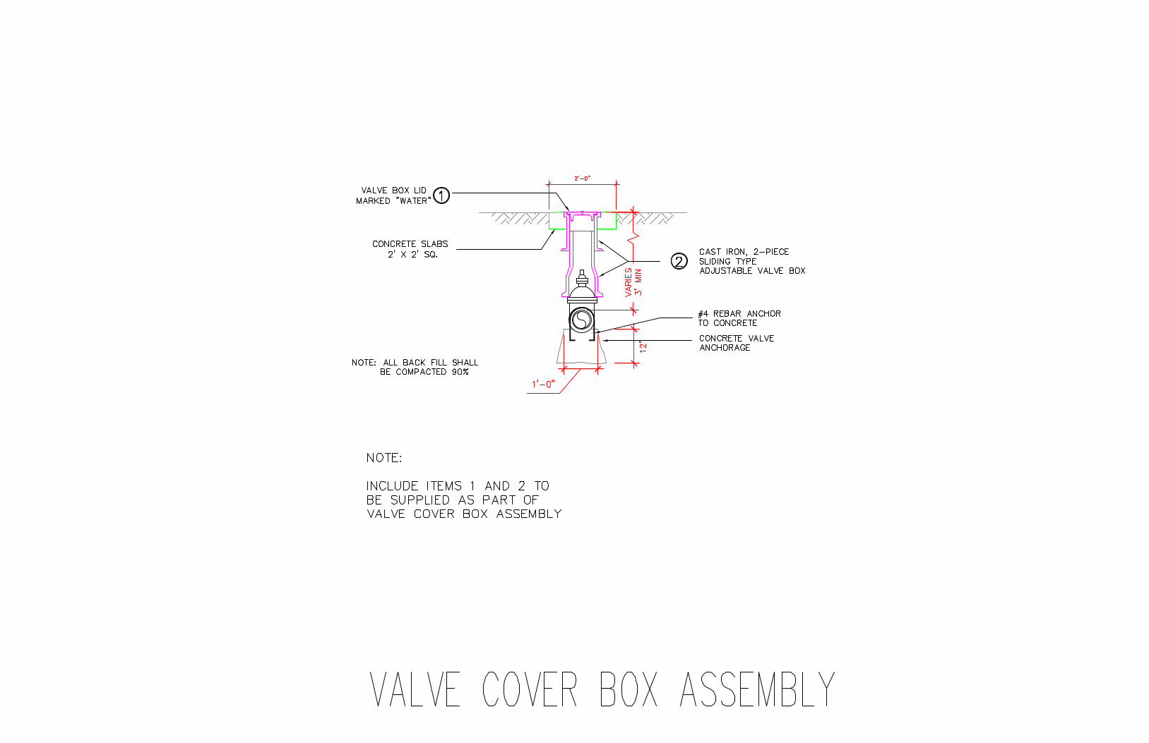
1.3.4 GATE VALVE BOX ASSEMBLY
1.3.4.1 Manufacturer: Tyler Pipe, Rich or equal.
1.3.4.2 Box Style: Two piece slip style valve box.
1.3.4.3 Nominal diameter of Gate Valve Box fits Gate Valve to be used.
1.3.4.4 Length: Sufficient for depth of bury indicated on plans.
1.3.4.5 Cover: Locking with pentagon nut and clearly marked as “water”.
1.3.4.6 Acceptable Products: Equal to the following:
Materials Supply & Delivery ofLEONE PIPELINE REPLACEMENT PROJECT 16
(a) Tyler Pipe 6855 valve box and lid.
(b) Rich 920 or 925 valve box and lid.
1.3.4.7 Cast iron and of the sliding type, sized for use with the appropriatevalve. Box shall extend from the body of the valve to the finishedgrade
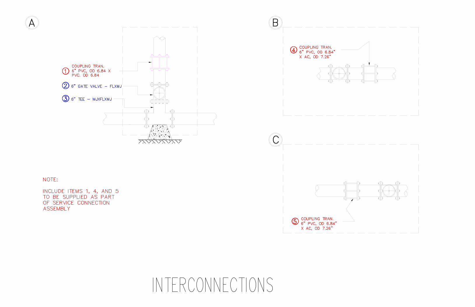
1.3.5 TRANSITION COUPLING HDPE PIPE TO AC PIPE:
1.3.5.1 Manufacturer: ROMAC Industries, Inc. STYLE 501 TransitionCoupling Series meet or exceed either AWWA C219, couplingspecification or ASPA approved equal.
1.3.5.2 CASTINGS: The end rings and center rings are cast from ductile(nodular) iron, meeting or exceeding ASTM A536.
1.3.5.3 GASKETS: are made from virgin Styrene Butadiene Rubber (SBR)compounds available for petroleum, chemical, or high temperatureservice.
1.3.5.4 BOLTS AND NUTS: 5/8 inch, high strength low alloy steel trackheadbolts. National coarse rolled thread and heavy hex nuts. Steel meetsAWWA C111 composition specifications.
1.3.5.5 COATINGS: Shop coating applied to cast parts for corrosionprotection in transit. Fusion bonded epoxy, liquid epoxy or othercoatings may be applied.
1.3.5.6 PRESSURE: when properly installed on a pipe that is within thecorrect outside diameter range, couplings in the ROMAC Style 501line can be used up to 260 psi.
1.3.5.7 SIZES AND RANGES: Must be 6” nominal size DIPS for the HDPEpipe end and 6” AC pipe OD range of the product. Manufacture willprovide the ranges and tolerances as approved by ASPA.
END SECTION
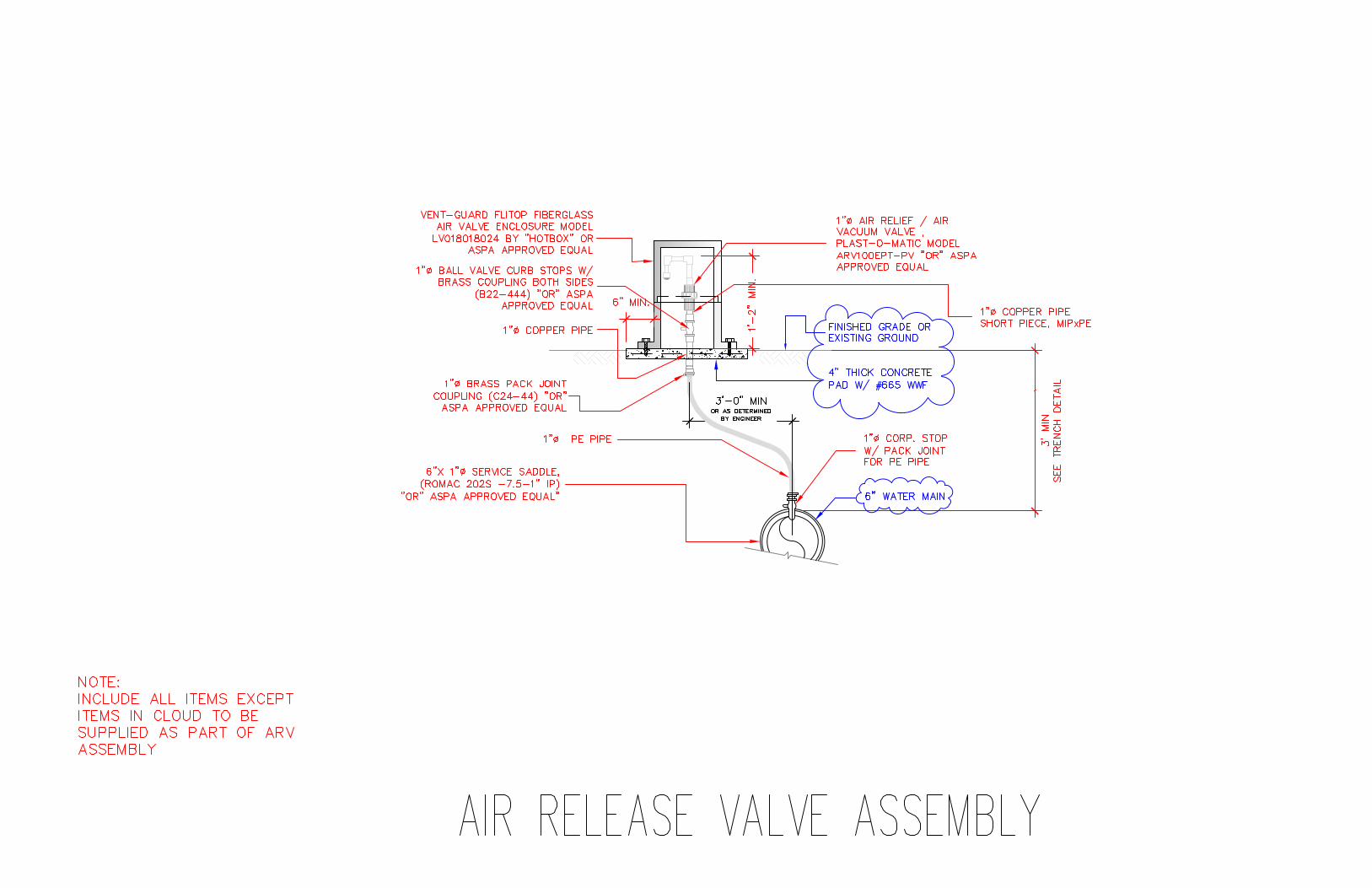
AIR RELEASE VALVE ASSEMBLY
PART 1 GENERAL
1.1 SECTION DESCRIPTION
Materials Supply & Delivery ofLEONE PIPELINE REPLACEMENT PROJECT 17
1.1.1 This specification includes but is not limited to Air Release Valve Assembly ofthe size and type shown on the plans, as an appurtenance to domestic water mains.These requirements include the type of valves and materials to be used, methodsand requirement for installation.
1.2 REFERENCES
1.2.1 AWWA C512 standard Specifications.
1.3 GENERAL
1.3.1 Conforms to EPA-AIS (American Iron and Steel) Certification.
1.3.2 Lay-out and configurations shall be in accordance to the specified drawingsprovided by ASPA-ESD
1.3.3 All Materials such as but not limited to 1” PVC pipe and fittings andappurtenances shall be NPT.
1.3.4 All materials such as but not limited to fittings and other parts or appurtenancesshall be made of Bronze or Copper. Galvanized Iron or Galvanized coating orlead content materials ARE STRICTLY PROHIBITED.
1.3.5 Valve Material: Top Quality Thermoplastics and Elastomers.
1.3.6 Valve Type: Normally-open air release/air vacuum valve.
1.3.7 Recommended Product:
1.3.7.1 AIR RELEAS VALVE: PLAST-O-MATIC Thermoplastic AirRelease Valve Model ARV100EPI-PV manufactured by Plas-O-Matic Valves, Inc. in Cedar Grove, New Jersy, USA or ASPAapproved equal.
1.3.7.2 FIBERGLASS ENCLOSURE BOX: VENT –GUARD Flip-TopFiberglass Air Valve Enclosure Model LV018018024 manufacturedby HOTBOX Enclosures in Jacksonville, Florida or ASPA approvedequal.
END SECTION
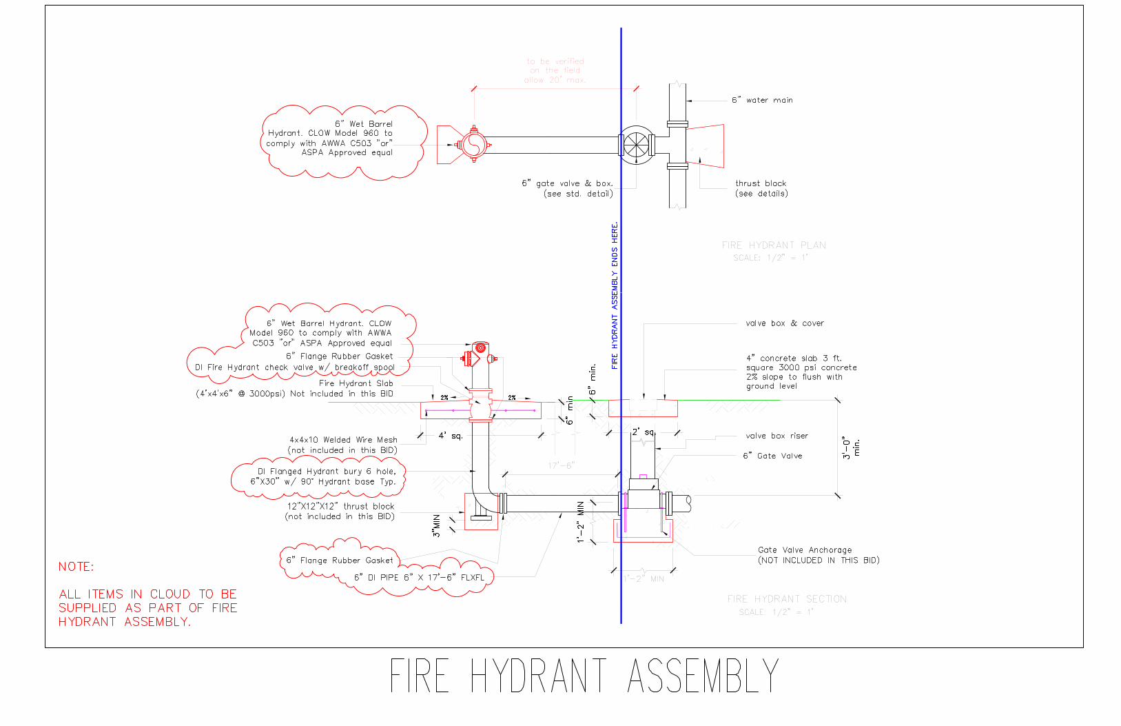
FIRE HYDRANT
PART 1 GENERAL
1.1 SECTION DESCRIPTION
1.1.1 This specification includes but is not limited to Fire Hydrant suitable forfirefighting and water emergencies.
Materials Supply & Delivery ofLEONE PIPELINE REPLACEMENT PROJECT 18
1.2 REFERENCES
1.2.1 AWWA C502, standards and specifications for Dry Barrel Hydrants.
1.2.2 AWWA C503, standards and specifications for Wet Barrel Hydrants.
1.3 GENERAL
1.3.1 Conforms to AWWA C502 for dry-barrel or C503 for wet-barrel, as specified inthe drawings.
1.3.2 Bury length is to the nearest 6 inches from the bottom of the connecting pipe tothe ground line of the hydrant.
1.3.3 Use two hose (2 ½ inch) and one pumper outlet (4 ½ inch) nozzles with threadsconforming to National Fire Protection Association (NFPA) 1963 for NationalStandard Fire Hose Coupling Screw Threads.
1.3.4 The size of the Hydrant is designated by the nominal diameter of the main valveopening. In no case shall the diameter of the main valve opening be less than 4inches.
1.3.5 Inlet connection is 6 inches flanged or hub connection.
1.3.6 The direction of rotation of the operating nut to open the hydrant is left(counterclockwise).
1.3.7 Paint the exterior of the hydrant in traffic or safety RED.
1.3.8 The outlet nozzle cap and chain is BRONZE.
1.3.9 Equipped with break off Flange and check valve (Model/LBI 400A).
1.3.10 Furnish Two (2) hydrant wrenches for this contract supplied by theManufacturer of Fire Hydrant.
1.3.11 Furnish One (1) Traffic Safety Flange Repair Kit including but not limited toall couplings, gaskets and connections necessary to replace a broken safety flange,as supplied by the manufacturer of Fire Hydrant.
1.3.12 Recommended Product is CLOW 960 Model manufactured by The CLOWValve Corona, California, USA or Equal.
END SECTION
SERVICE SADDLE
PART 1 GENERAL
Materials Supply & Delivery ofLEONE PIPELINE REPLACEMENT PROJECT 19
1.1 SECTION DESCRIPTION
1.1.1 This specification includes but is not limited to Service Saddle suitable for WaterService Connections and Saddle requirements for Blow-off Valve Assembly.
1.2 MATERIALS & REFERENCES
1.2.1 CASTING: The Saddle body is cast from ductile (nodular) iron, meeting orexceeding ASTM A 536, Grade 65-45-12.
1.2.2 GASKET: Gasket is made from Nitrile Butadiene Rubber (NBR) compoundedfor water and sewer service and a tolerance of petroleum products in accordancewith ASTM D 2000 MNC 610. Other compounds available for specialapplications.
1.2.3 STRAPS: Type 304 (18-8) heavy gauge Stainless Steel, two (2) inches wide tospread out clamping forces on the pipe. GMAW and GTAW welds. Passivatedfor corrosion resistance. A double strap is required.
1.2.4 BOLTS, NUTS: For 3”, ½” UNC roll thread Type 304 (18-8) Stainless Steelbolts with heavy hex nuts. 4” and above use 5/8” UNC roll thread Type 304 (18-8) Stainless Steel bolts with heavy hex nuts. All welds fully passivated forenhanced corrosion resistance. Nuts coated to prevent galling.
1.2.5 WASHERS: ½” or 5/8” flat, Type 304 (18-8) Stainless Steel and plastic washerto prevent galling.
1.2.6 SPRING WASHERS: ½” or 5/8” flat, Type 304 (18-8) Stainless spring washersmanufactured from a special grade of Stainless Steel used in the making ofsprings.
1.2.7 COATING: Casting is coated with fusion bonded black nylon, 10-12 mils thick,with a dielectric strength if 1,000v/mil.
1.2.8 PRESSURE RATING: Working pressures up to 150 psi when properly installedon a pipe within the correct outside diameter range.
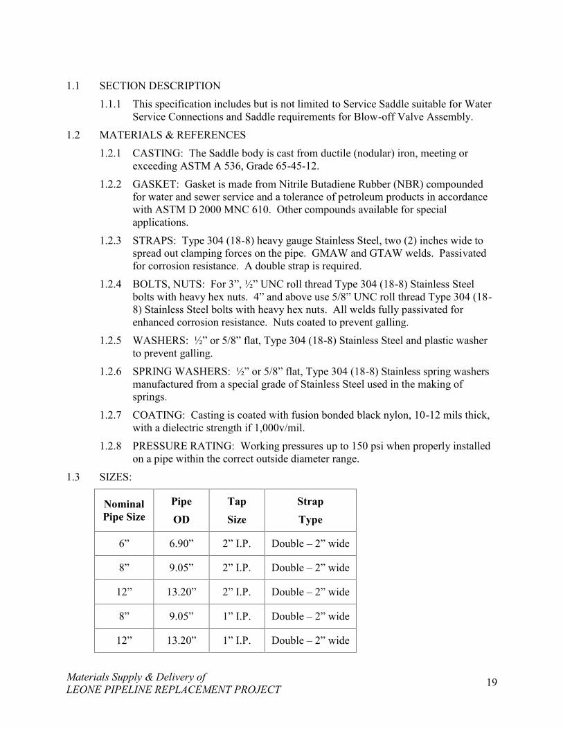
1.3 SIZES:
NominalPipe Size
PipeOD
TapSize
StrapType
6” 6.90” 2” I.P. Double – 2” wide
8” 9.05” 2” I.P. Double – 2” wide
12” 13.20” 2” I.P. Double – 2” wide
8” 9.05” 1” I.P. Double – 2” wide
12” 13.20” 1” I.P. Double – 2” wide
Materials Supply & Delivery ofLEONE PIPELINE REPLACEMENT PROJECT 20
1.4 GENERAL
1.4.1 Use standard tapping saddles designed for use on PVC piping in accordance withAWWA C605
1.4.1.1 Operating temperatures are limited to 85° F maximum and 32° Fminimum.
1.4.1.2 Operating pressure is limited to 150 psi or the rating of the pipe,whichever is less.
1.4.1.3 Pipe system must be designed to compensate for Pipe movement so asto prevent fittings from migrating or rotating on the pipe.
1.4.1.4 Products are intended for use in underground service only.
1.4.1.5 Proper restraints must be used when coupling pipe ends to preventpullout from hydraulic forces or temperature changes.
1.4.2 Recommended product is ROMAC Service Saddle Type 202N-H Nylon Saddlewith Stainless Steel Double Strap for use on HDPE (DIPS) Pipe or FORD DuctileIron Epoxy Coated Saddle Model # FCD202-690-CC7 or ASPA approved equal.
END SECTION
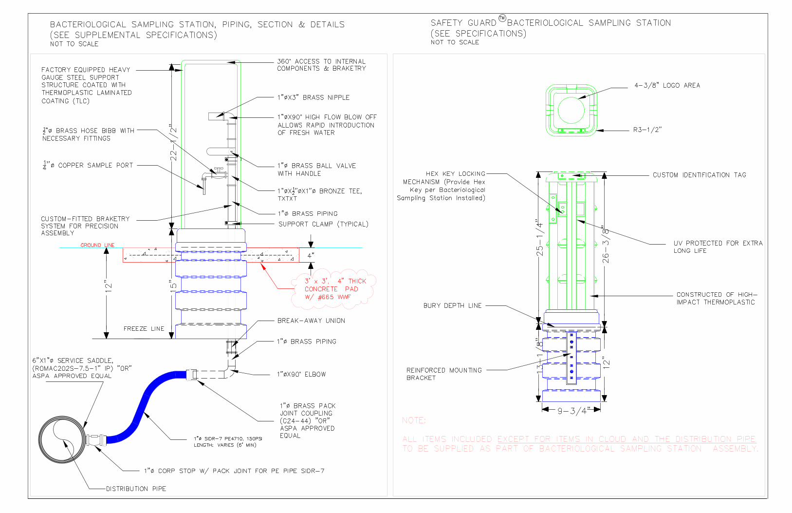
BACTERIOLOGICAL SAMPLING STATION
PART 1 GENERAL
1.1 SECTION DESCRIPTION
1.1.1 This specification includes but is not limited to Bacteriological Sampling Stationsuitable for Water Sampling Activities.
1.2 MATERIALS
1.2.1 SUPPORT STRUCTURE: Shall be factory-equipped heavy gauge steel supportstructure coated with Thermoplastic Laminated Coating (TLC).
1.2.2 BRACKET SUPPORT: Shall be factory-equipped Custom fitted bracketrysystem for precision assembly and with 360° access to internal components andbracketry.
1.2.3 INTERNAL COMPONENTS: Pipes, fittings, appurtenances shall be made ofBrass and sample port must be made of Copper.
1.2.4 COVER: Shall be constructed of high-impact Thermoplastic with UV Protectedfor extra-long life. Bury Depth line shall be reflected and visible. Base of Cover
Materials Supply & Delivery ofLEONE PIPELINE REPLACEMENT PROJECT 21
must have a stability features to eliminate the need for additional mounting stakesor concrete pad and re-enforced mounting brackets shall be part of the base.
1.2.5 SECURITY LOCK FOR COVER: A hex key locking Mechanism shall beincluded.
1.2.6 IDENTIFICATION PLATE/TAG: A Custom identification tag shall be includedon the top portion of the cover, visible for water crew’s identification.
1.3 FINISH
1.3.1 All Bacteriological Sampling Station must be colored BLUE (water).
1.4 DIMENSION: See drawings provided.
1.5 GENERAL
1.5.1 ALL Bacteriological Sampling Station shall ONLY BE FACTORYFABRICATED. NO Field/Site Fabrication is allowed.
1.5.2 Recommended product is SAFETY GUARD Model #SG-BSS-01 withEnclosure Model #SG-77 or ASPA approved equal.
END SECTION
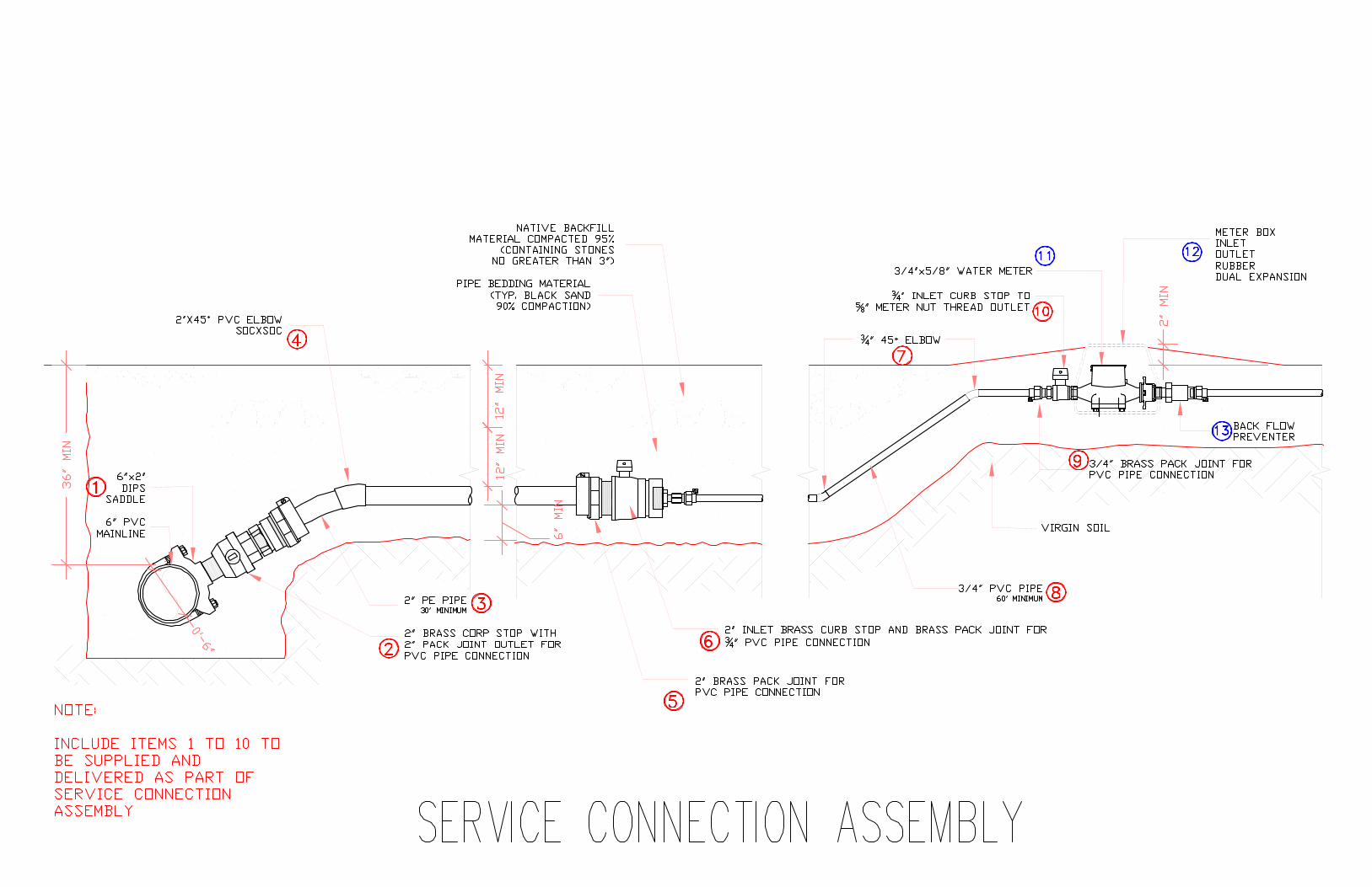
SERVICE CONNECTION ASSEMBLY
PART 1 GENERAL
1.1 SECTION DESCRIPTION
1.1.1 This specification includes but is not limited to Service Connection Assemblyfrom PVC Mains to existing service water meter box.
1.2 MATERIALS & REFERENCES
1.2.1 6” x 2” SERVICE SADDLE: See material specifications under Service Saddle.
1.2.2 2” & ¾” PVC: See material specifications under PVC.
1.2.3 2” CORP. STOP WITH 2” PACK JOINT FOR PVC PIPE: shall be designed andmanufactured to conform to AWWA Standard C800.
1.2.4 2” CURB STOP WITH REDUCING TO ¾”: shall be designed andmanufactured to conform to AWWA Standard C800.
1.2.5 2” CURB STOP WITH METER NUT THREAD TO 5/8” WATER METER:shall be designed and manufactured to conform to AWWA Standard C800.
Materials Supply & Delivery ofLEONE PIPELINE REPLACEMENT PROJECT 22
1.3 SIZES:
1.3.1 Sizes provided by the manufacturer as per standard plan and this specification.
1.4 PRODUCT:
1.4.1 6” x 2” SERVICE SADDLE: See material specifications under Service Saddle.
1.4.2 2” & ¾” PVC SCHEDULE 80 PIPE: See material specifications under PVCPipe.
1.4.3 2” CORP. STOP WITH 2” PACK JOINT FOR PVC PIPE
1.4.4 2” CURB STOP WITH REDUCING TO ¾”
1.4.5 2” CURB STOP WITH METER NUT THREAD TO 5/8” WATER METER:Recommended product is Model # B-63-332W-NL, manufactured by FORDMETER BOX COMPANY, INC. in Wabash, Indiana, USA or ASPA approvedequal.
END SECTION
PVC SCHEDULE 80 PIPE
PART 1 GENERAL
1.1 SCOPE
1.1.1 This specification includes but is not limited to Service Connection Assemblyfrom fusible PVC Mains to existing service water meter box.
1.1.2 This specification outlines minimum manufacturing requirements for PolyvinylChloride (PVC) Schedule 80 iron pipe size (IPS) pressure pipe. This pipe shouldmeet and or exceed the industry standards and requirements as set forth by theAmerican Society for Testing and Materials (ASTM)
1.2 PIPE DESCRIPTION
1.2.1 Corrosion resistant pressure pipe IPS sizes 3/4” and 2” for use at temperatures upto and including 140 °F and pressure rating 200 psi Generally resistant to mostacids, bases, salts, aliphatic solutions, oxidants, and halogens. Pipe exhibitsexcellent physical properties and flammability characteristics (independentlytested flame and smoke characteristics-ULC).
Materials Supply & Delivery ofLEONE PIPELINE REPLACEMENT PROJECT 23
1.2.2 Product marking shall meet the requirements of ASTM D1785 and shall include:the manufacturer’s name (or the manufacturer’s trademark when privatelylabeled); the nominal pipe size; the material designation code; the pipe scheduleand pressure rating in psi for water @ 73°F; the ASTM designation D1785; theindependent laboratory’s seal of approval for potable water usage; and the dateand time of manufacture.
1.3 QUALITY ASSURANCE
1.3.1 All PVC Schedule 80 pipe shall be manufactured from a Type I, Grade IPolyvinyl Chloride (PVC) compound with a Cell Classification of 12454 perASTM D1784. The pipe shall be manufactured in strict compliance to ASTMD1785, consistently meeting and/or exceeding the Quality Assurance testrequirements of this standard with regard to material, workmanship, burstpressure, flattening, and extrusion quality. The pipe shall be manufactured in theUSA, using domestic materials, by an ISO 9001 certified manufacturer. All pipeshall be stored indoors after production at the manufacturing site until shippedfrom factory. This pipe shall carry the National Sanitation Foundation (NSF) sealof approval for potable water applications.
END SECTION