Embed Size (px)
Citation preview
UNCLASSIFIED
AD NUMBER
CLASSIFICATION CHANGESTO:FROM:
LIMITATION CHANGESTO:
FROM:
AUTHORITY
THIS PAGE IS UNCLASSIFIED
ADA492534
UNCLASSIFIED
SECRET
Approved for public release; distribution isunlimited. Document partially illegible.
Distribution authorized to DoD only; ForeignGovernment Information; NOV 1949. Otherrequests shall be referred to British Embassy,3100 Massachusetts Avenue, NW, Washington, DC20008. Document partially illegible.
DSTL ltr dtd 20 Feb 2007; DSTL ltr dtd 20 Feb2007
TECH. NOTE R.P.D. 22
TECH. NOTE R.P.D. 22
CONFIDENTIAL HfUTISH SECRET Equal* UNITED STATES SECRET
-/Ml NbT SUITABLE FOR FURTHE* OSTiHUTi'
FARNBOROUGH, HANTS
V.
Inv §3
INV90
2 i-3
TECHNICAL NOTE No: R.P.D. 22
A METHOD OF CALCULATING THE WEIGHT AND DIMENSIONS
OF A TURBO PUMP FOR ROCKET PROPELLANTS
by
D.J.SAUNDERS, B.Sc.(Eng.), A.F.R.Ae.S.,
ROCKET PROPULSION DEPARTMENT,
WESTCOTT
w
I
«* ^TS^r
„,,., MJTOMATJC HECIUDIN&
de to
Ues«oy INVENTORY
20081208329 29 I REVIEW ON ^Tt^ir. ~7?
MINISTRY SUPPLY
THIS DOCUMENT IS THE PROPERTY OF H.M GOVERNMENT AND ATTENTION IS CALLED TO THE PENALTIES ATTACHING TO
ANY INFRINGEMENT OF THE OFFICIAL SECRETS ACT, 1911-1939
It Is intended for the use of the recipient only,and for communication to such officers under him as may require to be acquainted with its contents in the course of their duties. The officers exercising this power of communication are responsible that such Information is imparted with due caution and reserve. Any person other than the authorised holder, upon obtaining possession of this document, by finding or otherwise,should forward it, together with his name and address, in a closed envelope to>
THE SECRETARY. MINISTRY OF SUPPLY. MILL8ANK. LONDON. S.W.I.
Letter postage need not be prepaid, other postage will be refunded. All persons arc hereby warned that the unauthorised retention or destruction of this document is an
offence against the Official Secrets Act
IAL
£. )
Class No. 621.67 : 621.455-44
.• Tebhnical Note No. R.P.D. 22
' FAR
November, 1 949
ROYAL AIRCRAFT ESTABLISHMENT,'7ARNB0R0UGH
A Method of Calculating the Weight and Dimensions of a Turbo Pump for Rocket Propellants
by
D. J. Saunders, B.So.(Eng.), A.P.R.Ac.S.
SUMARY
This note indicates methods by which the weight and size of a rocket motor turbo pump may be approximately obtained, in order to help the rocket motor designer to consider what type of fuel expulsion he should employ. Some examples are given, together with estimates of steam consumption. A suggestion is also given for reducing the turbo- pump weight.
/» / o«» r ->. 2>6 c/c t J.
Technical Note No. R.P.D. 22
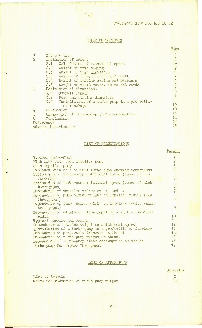
LIST OP CONTENTS
1 Introduction 2 Estimation of weight
2.1 2.2 2.3 2.4 2.5 2.6
Calculation of rotational speed Weight of pump casing Weight of pump impellers Weight of turbine rotor and shaft Weight of turbine casing and bearings Weight of fluid seals, bolts and studs
3 Estimation of dimensions 3.1 Overall length 3.2 Pump and turbine diameters 3.3 Installation of a turbo-pump in a projectile
or fuselage 4 Discussion 5 Estimation of turbo-pump steam consumption 6 Conclusions References Advance Distribution
Page
3 3 4 5 6 7 8 8 8 9 9
10 10 11 12 13 13
LIST OP ILLUSTRATIONS
Typical turbo-pump High flow rate open impeller pump Open impeller pump Exploded view of a bi-fuel turbo pump showing components Estimation of turbo-pump rotational speed (pumps of low
throughput) Estimation of turbo-pump rotational speed (pumps: of high
throughput) Dependence of impeller radius on X and Y Dependence of pump casing weight on impeller radius (low
throughput) Dependence of pump casing weight on impeller radius (high
throughput) Dependence of aluminium alloy impeller weight on impeller
radius Typical turbine and casing Dependence of turbine weight on rotational speed Installation of a turbo-pump in a projectile or fuselage Dependence of projectile diameter on thrust Dependence of turbo-pump weight on thrust Dependence of turbo-pump steam consumption on thrust Turbo-pump for Higher Throughput
Figure
1 2 3 4
6 7
10 11 12 13 14 15 16 17
LIST OP APPENDICES
List of Symbols Means for reduction of turbo-pump weight
Appendix
I II
- 2 -
Technical Note No. R.P.D. 22
1 Introduction
In order to design a particular rocket motor, the designer requires data on the nature of the propellants and their specific impulse, the thrust and the duration of the motor and whether repeat- ability of operation is required or not.
Though it is possible to design a combustion chamber, injector, etc., from this information it is not always obvious what type of propellant supply to the combustion chamber should be used to give low weight and simplicity or ease to manufacture.
The chief methods of removing the propellants from the tanks and supplying them to the combustion chamber under pressure, are by means of
(1) A turbo-pump
(2) Gas pressure in the tanks.
Some of the various ways of producing gas and applying it to the propellants have already been discussed^ and this note confines itself to the first method with the object of enabling designers to assess the approximate weight, dimensions and general performance of a turbo-pump to meet any particular requirement.
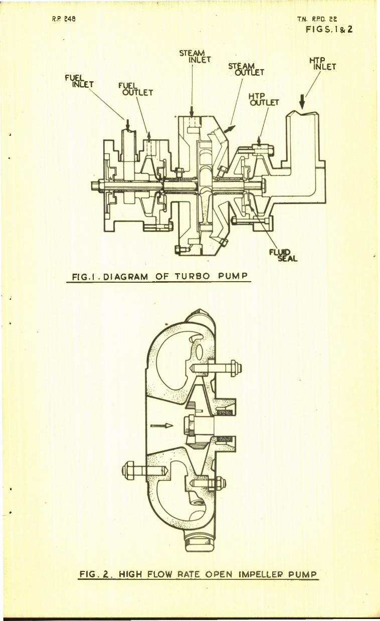
Turbo-pumps were used in the German V.2 and the Walter 109-509 rocket motors, but these pumps were made on more or less conventional lines, and entailed rather complicated construction. The type of pump considered now is the Barske open impeller pump (with fluid seals) coupled with a bucket wheel type turbine^. Pig.1 shows an example of this type of turbo-pump designed for an 1800 lb thrust rocket motor with a duration of two minutes. It is evident that the type of construc- tion shown here greatly facilitates manufacture.
The most convenient layout of turbo-pump consists of a central turbine driving an oxidant pump on one side with a fuel pump on the other and having a common driving shaft to all three units. The pump shown in Fig.1 which is typical except for the shaft protruding from the fuel pump, will form the basis of the discussion. Pig.2 shows a single higher flow rate pump, the German 'Enzian' oxidant pump, whose characteristics will also be used in the discussion.
2 Estimation of Weight
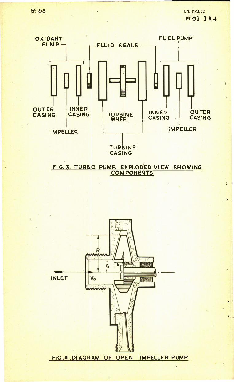
The turbo-pump as a whole can be broken down into the following components as indicated in Pig.3.
(1
(2
(3
(V (S (6
(7
(8
Oxidant pump casing
Fuel pump casing
Oxidant pimp impeller
Fuel pump impeller
Turbine wheel and shaft
Turbine and bearing casing including bearings
Fluid seals
Studs, bolts and other extras.
The method of oaloulating the weights of the pump casing will, of course, be the same for both fuel and oxidant, and it is only necessary
-3 -
Technical Note No. R.P.D. 22
to substitute the relevant conditions. Similarly the impellers follow the same lines, but the turbine components will be quite different. The data which must be given (for both fuel and oxidant) are:-
(1) Propellant throughput - Q lb/sec.
(2) Propellant delivery pressure - p lb/sq.. ft.
(3) Propellent density - W lb/cu.ft.
•Where necessary the symbols used will have suffix 0 or F to distinguish oxidant and fuel respectively. These and all other symbols are collected in Appendix I.
Prom the foregoing data and with certain assumptions, which are detailed later and can be justified by practical experience, it is possible to proceed. It is first necessary to estimate the pump rotation speeds and thence deduce the impeller and turbine radii. The weights of both impellers and casings are a function of these radii, whereas the turbine weight is dependent on an inverse function of rotational speed.
2.1 Calculation of Rotational Speed
The criteria for pump rotational speed are the axial velocity v of the fluid at the inlet of the pump with the largest throughput (usually the oxidant pump) and the peripheral velocity u at the inner radius of this pump's impeller.
Normally the value of v should not exceed 10 ft/sec, but higher values may be realized if the tanks are slightly pressurized or a screw type booster (as on the German 109-509) is used. In the latter case for weight calculation purposes v may be taken as a maximum of 15 ft/seo.
Consider the simple diagram of an open impeller pump shown in Fig.4- At the inlet
% r2 v = %
i.e.
r = °'56 /l^ ft - CO where r is the pump inlet radius in feet.
The peripheral velocity at the impeller inner radius
u = 2% rn ft/sec (2)
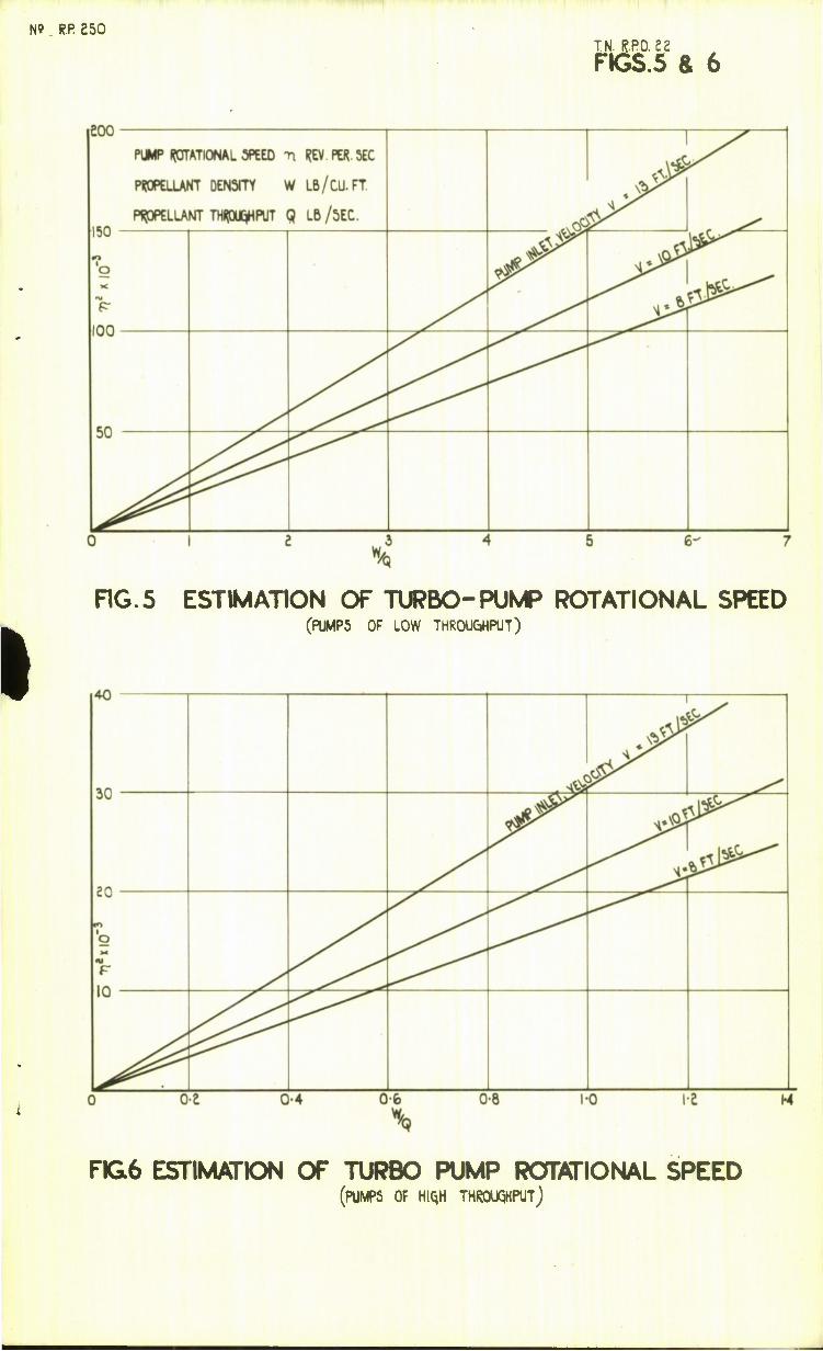
where n is the rotational speed in revolutions per second. At the present stage of development, the maximum value of u is considered as 170 ft/sec. Subs tituting.ihis-value in (2) and eliminating r by using (1)
» = W.2 M (3)
or
Q
n2 = 2320 v 2 Q
-4-
Technical Note No. R.P.D. 22
Pig. 5 and 6 show — plotted against 1 0"^ n for various values pf v . Q
2.2 Weight of pump casing
Given the propellant throughput, pressure and density and the values of the rotational speed obtained from Pig. 5 or 6, the radius of each impeller can be obtained as follows:-
The delivery pressure p = static pressure + dynamic pressure lb/sq ft
The static pressure = w l1^ ~ u ) lb/sq ft
where U is the peripheral velocity at the outer radius of the impeller in ft/scc.
This pressure is normally obtained fully.
The dynamic pressure is only partly obtained, ty is a factor indicating the pressure recovery; it depends on the fluid viscosity and the internal surface finish of the diffusers. An average value of f is 0.2, although higher values can be realized. This value, however, will be assumed in these calculations.
—o The dynamic pressure = f ~- lb/sq ft
.'. p = * (U2 • u2) WU£ 2g 2g
JL 2S
(1 + i) U2 - u2 j lb/sq ft
As the pressure is given, this equation can be used, after substituting for the peripheral velocities to obtain the impeller radius
E • /=h *+"") ft » Substituting for r from (1) and inserting the value of ty = 0.2,
then
R = /l.36X + 0.261 .I2 ft (5)
where
X = -£- and I = -2- . rpt vw
Pig. 7 shows the dependence of R2 on X and Y .
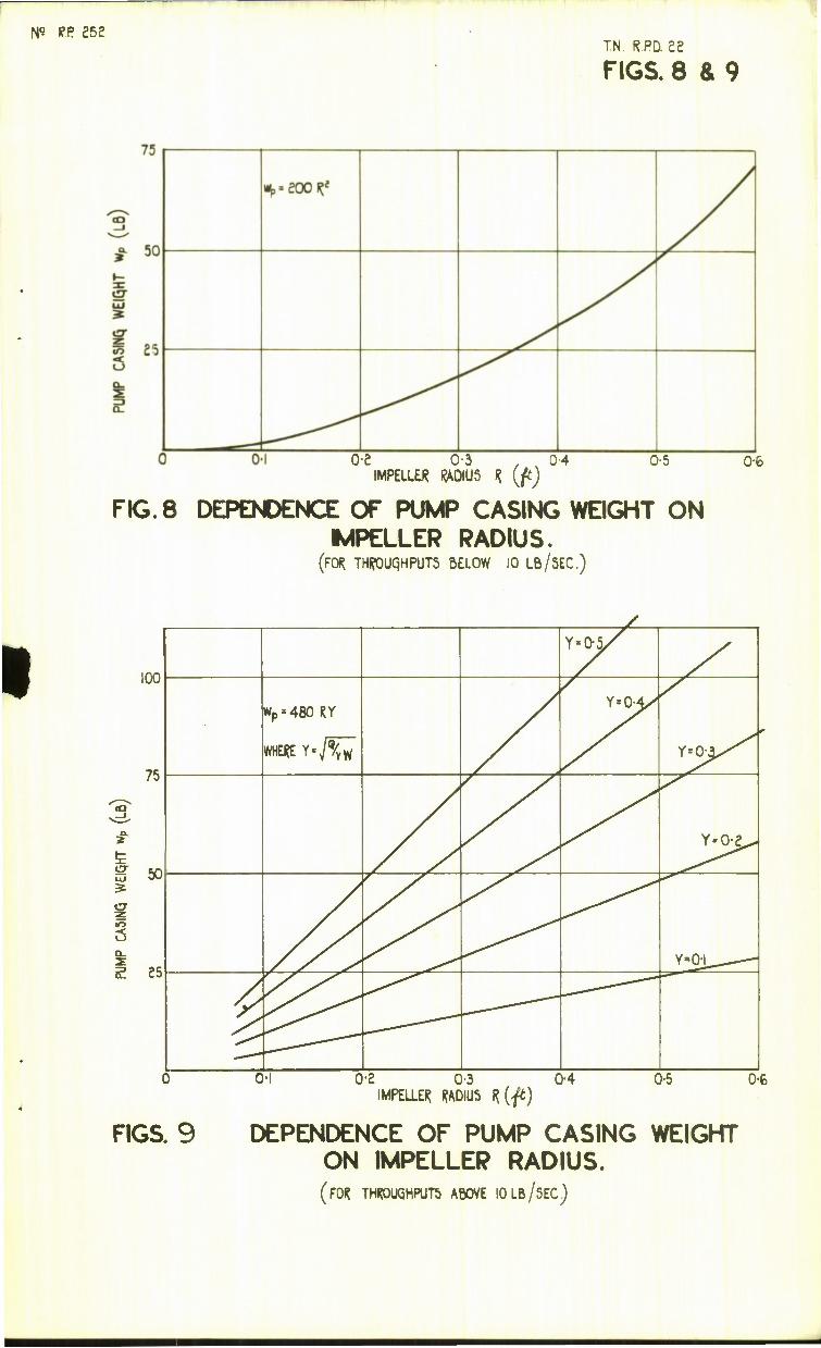
Pump casings for throughputs below 10 lb/seo, when a maximum of three separate delivery diffusers are used, can be considered as formed of two flat plates of uniform thickness. The pimp" shown in Pig. 4 could be considered as an example of such a construction.
- <S -
Technical Note No. R.P.D. 22
Weight of casing wp = k] R2 lb
where k. is a constant.
The weight of the oxidant pump casing with two diffusers shown in Pig. 1 was 2 lb; the impeller has a radius of 0.1 ft, and is made of aluminium alloy as is usually the case. For this pump which may be considered as typical
kj = 200
hence
wp = 200 R2 lb (6)
Pig. 8 shows this relationship for throughputs up to 10 lb/sec.
For pumps where more than three diffusers are used it is more convenient to employ a collecting ring forming part of the pump casing into which the fuel or oxidant flows from the diffusers. The total flow is then taken from this ring. The pump shown in Pig. 2 is an example of this type of construction. The mass of the pump is then concentrated at its circumference, hence only the weight of this portion will be considered. For the purposes of weight estimation it is assumed that the thickness of the wall of this collecting ring does not vary much.
The weight of the casing (neglecting the side walls of the pump) is then given by
w = k2 Rb lb
where ^ is a constant and b the impeller width at the blade root. A reasonable figure for b is
b = £ = 0.28 /4r ft 2 \l vW
Substituting this value of b , and the weights and dimensions for the pump shown in Pig.2, then
= 480 R y lb (7)
Pig. 3 shows the dependence of wp on R for different values of Y .
2.3 Weight of Pump Impellers
The impeller weights are very small compared with pump weights, but although they do not affect the total weight of the pump materially their weight and positions on the shaft must be taken into account when consider- ing the critical rotational speed of the turbine.
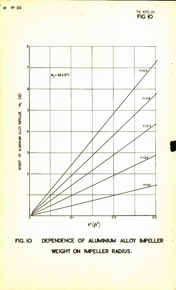
The pump impeller weight is given by:
WI = ty. R2 b lb
where kj, is a constant.
- 6 -
Technical Note No. R.P.D. 22
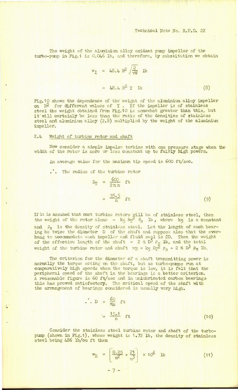
The weight of the aluminium alloy oxidant pump impeller of the turbo-pump in Fig. 1 is 0.0k.G lb, and therefore, by substitution we obtain
wz = tf.h.RZj-^ lb
= 2*3.4 R2 Y lb (8)
Pig.10 shows the dependence of the weight of the aluminium alloy impeller on R2 for different values of I , If the impeller is of stainless steel the weight obtained from Fig.10 is somewhat greater than this, but it will certainly be less than the ratio of the densities of stainless steel and aluminium alloy (2.8) multiplied by the weight of the aluminium impeller.
2.4 Weight of turbine rotor and shaft
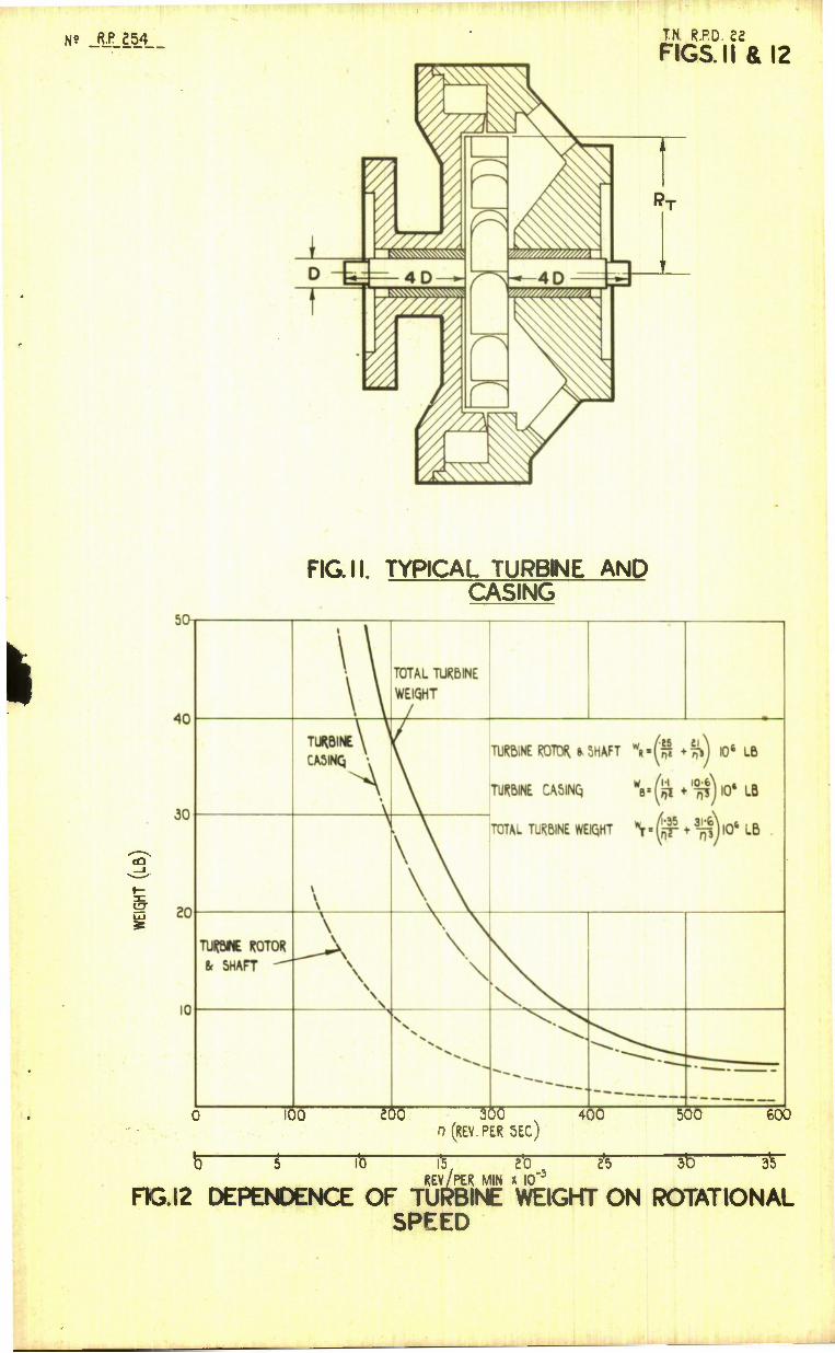
Now consider a simple impulse turbine with one pressure stage when the width of the rotor is more or less constant up to fairly high powers.
An average value for the maximum tip speed is 600 ft/sec.
.". The radius of the turbine rotor
Bp . iffi. ft 1 27Cn
95.5 n ft (9)
If it is assumed that most turbine rotors will be of stainless steel, then the weight of the rotor alone = kc; Rp2 Ps lb , where k^ is a constant
and Ps is the density of stainless steel. Let the length of each bear- ing be twice the diameter D of the shaft and suppose also that the over- hang to accommodate each impeller and fluid seal is 2D. Then the weight of the effective length of the shaft = 2 % T$ ps lb, and the total weight of the turbine rotor and shaft WR = k.^ Rrp2 ps + 2 % IK ps lb.
The criterion for the diameter of a shaft transmitting power is normally the torque acting on the shaft, but as turbo-pumps run at comparatively high speeds when the torque is low, it is felt that the peripheral speed of the shaft in the bearings is a better criterion. A reasonable figure is 60 ft/sec and in unlubricated carbon bearings this has proved satisfactory. The critical speed of the shaft with the arrangement of bearings considered is usually very high.
.'. D = |2 ft
"• ^r « Oo)
Consider the stainless steel turbine rotor and shaft of the turbo- pump (shown in Fig.1), whose weight is 1.72 lb, the density of stainless steel being 486 lb/cu ft then
« - 0.25 21
- 7 -
x 106 lb (11)
Technical Note No. R.P.D. 22
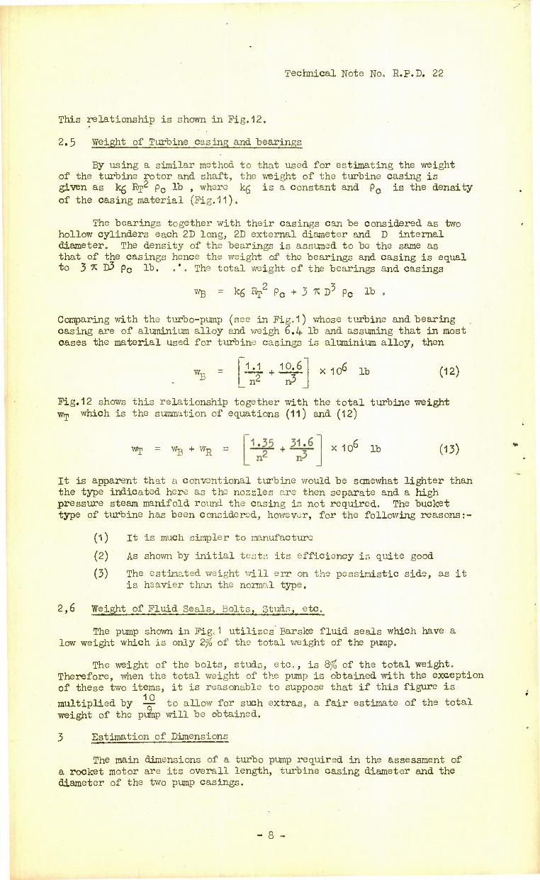
This relationship is shown in Fig.12.
2.5 Weight of Turbine casing and bearings
By using a similar method to that used for estimating the weight of the turbine rotor and shaft, the weight of the turbine casing is given as kg Erp^ pc lb , where kg is a constant and pc is the density of the casing material (Fig.11).
The bearings together with their casings can be considered as two hollow cylinders each 2D long, 2D external diameter and D internal diameter. The density of the bearings is assumed to be the same as that of the casings hence the weight of the bearings and casing is equal to 3 ft D3 pc lb. .*. The total weight of the bearings and casings
wB = kg Rj2 pc + 3 ft D5 pc lb .
Comparing with the turbo-pump (see in Fig.1) whose turbine and bearing casing are of aluminium alloy and weigh 6.4 lb and assuming that in most cases the material used for turbine casings is aluminium alloy, then
WB 1.1 10.6
n2 + n3 X106 lb (12)
Fig. 12 shows this relationship together with the total turbine weight wT which is the summation of equations (11) and (12)
Wj = Wg + W^ x 106 lb (13)
It is apparent that a conventional turbine would be somewhat lighter than the type indicated here as the nozzles are then separate and a high pressure steam manifold round the casing is not required. The bucket type of turbine has been considered, however, for the following reasons:-
(1) It is much simpler to manufacture
(2) As shown by initial tests its efficiency is quite good
(3) The estimated weight will err on the pessimistic side, as it is heavier than the normal type.
2,6 Weight of Fluid Seals, Bolts, Studs, etc.
The pump shown in Fig. 1 utilizes Barske fluid seals which have a low weight which is only 2% of the total weight of the purnp.
The weight of the bolts, studs, etc., is 8% of the total weight. Therefore, when the total weight of the pump is obtained with the exception of these two items, it is reasonable to suppose that if this figure is
10 multiplied by — to allow for such extras, a fair estimate of the total weight of the pump will be obtained.
3 Estimation of Dimensions
The main dimensions of a turbo pump required in the assessment of a rocket motor are its overall length, turbine casing diameter and the diameter of the two pump casings.
- 8 -
Technical Note No. R.P.D. 22
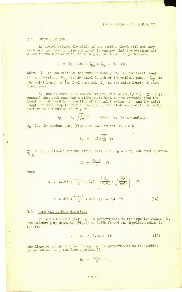
3.1 Overall Length
As stated before, the width of the turbine wheel will not vary- much with increase in size and if it is assumed that the bearings are close to the turbine wheel as in Fig.1, the total length becomes:
L = •%> + 2% + -dp + -tp + 2l3 ft
where &p is the width of the turbine wheel, &g is the axial length
of each bearing, £p is the axial length of the oxidant pump, £p-, is
the axial length of the fuel pump and ts is the axial length of each fluid seal.
£T can be taken as a nominal figure of 1 in (0.083 ft). If it is assumed that each pump has a right angle bend at its entrance then the length of the bend is a function of the inlet radius r , and the axial length of each pump is only a function of the blade root width b which in turn is a function of r , or
Jw ft where ky is a constant.
£p for the oxidant pump (Fig.1) is 0.25 ft and ky = 2.6
2.6./^ ft
If D ft is allowed for the fluid seals, i.e. 6S = D ft, but from equation (10)
B . 1M «
then
0.083 + H^i + 2.6 n
I Qo
v0W0
QF
vpWp ft
= 0.083 + ^^ + 2.6 (I0 + Yp) ft (14)
3.2 Pump and turbine diameters
The diameter of a pump Dp is proportional to its impeller radius R. The oxidant pump diameter (Fig.1) is 0.354 ft and the impeller radius is 0.1 ft.
DD = 3.54 R ft (13)
The diameter of the turbine casing Dp is proportional to the turbine rotor radius % , but from equation (9)
RT . !5j£ • ft ,
- 9 -
Technical Note No. R.P.D. 22
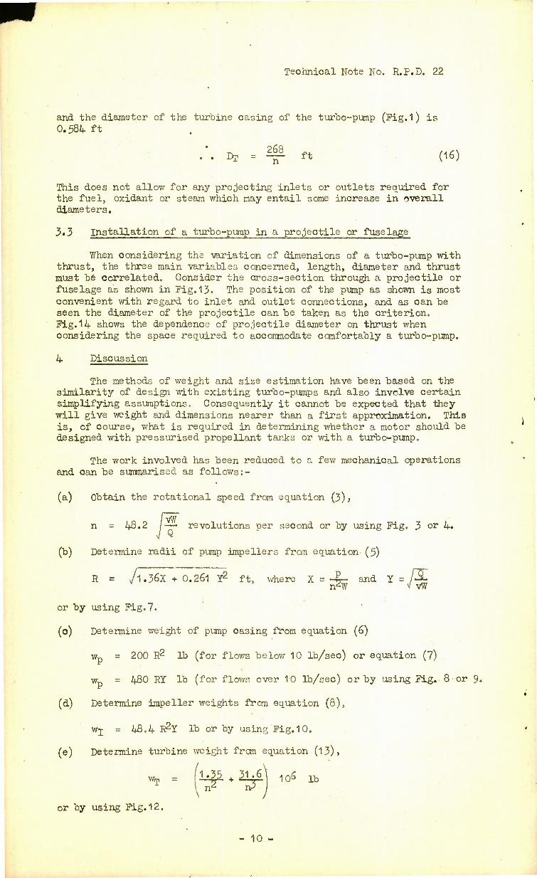
and the diameter of the turbine casing of the turbo-pump (Fig.1) is 0.584 ft
.'. Dr = ^ ft (16)
This does not allow for any projecting inlets or outlets required for the fuel, oxidant or steam which may entail some increase in overall diameters.
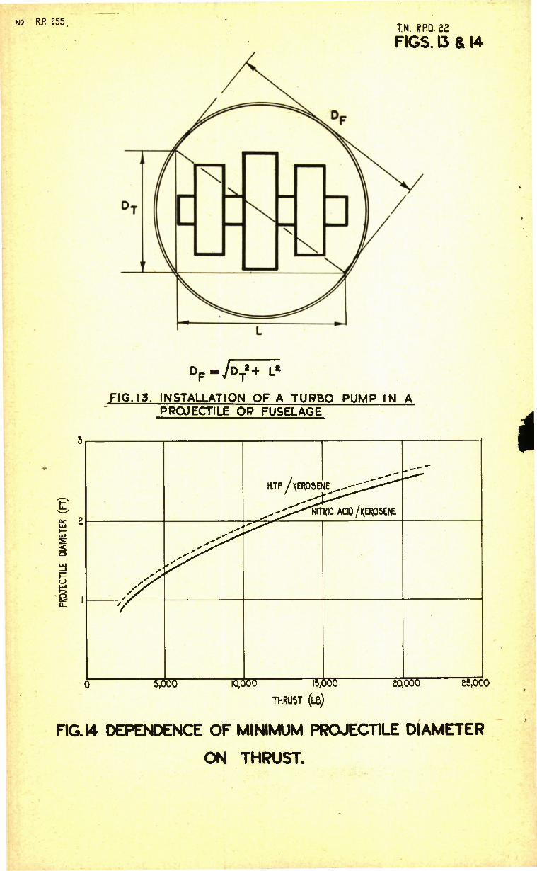
3.3 Installation of a turbo-pump in a projectile or fuselage
When considering the variation of dimensions of a turbo-pump with thrust, the three main variables concerned, length, diameter and thrust must be correlated. Consider the cross-section through a projectile or fuselage as shown in Pig. 13. The position of the pump as shown is most convenient with regard to inlet and outlet connections, and as can be seen the diameter of the projectile can be taken as the criterion. Pig.14 shows the dependence of projectile diameter on thrust when considering the space required to accommodate comfortably a turbo-pump.
4 Discussion
The methods of weight and size estimation have been based on the similarity of design with existing turbo-pumps and also involve certain simplifying assumptions. Consequently it cannot be expected that they will give weight and dimensions nearer than a first approximation. This is, of course, what is required in determining whether a motor should be designed with pressurised propellant tanks or with a turbo-pump.
The work involved has been reduced to a few mechanical operations and can be summarised as follows:-
(a) Obtain the rotational speed from equation (3)3
n = 48.2 /— revolutions per second or by using Pig. 3 or 4.
(b) Determine radii of pump impellers from equation- (5)
R = /l.36X + 0.261 Y2 ft, where X = -8- and Y = /3jL n^W v vW
or by using Pig.7.
(o) Determine weight of pump casing from equation (6)
wp = 200 R2 lb (for flows below 10 lb/seo) or equation (7)
wn = 480 RY lb (for flov/s over 10 lb/sec) or by using Pig.. 8 or 9. Jr
(d) Determine impeller weights from equation (8),
wj = 48.4 R2Y lb or by using Pig. 10.
.(e) Determine turbine weight from equation (13),
or by using Pig.12.
- 10 -
Technical Note No. R.P.D. 22
1 0 (f) Obtain the total and multiply by -—. to allow for fluid seals,
studs, bolts, etc'
The dimensions are obtained from the following: -
(g) Total length L = 0.083 + ~~ + 2-6 (*0 + Yp) ft .
(h) Pump diameter Dp = 3.54 R ft .
(i) Turbine casing diameter Dj = ft .
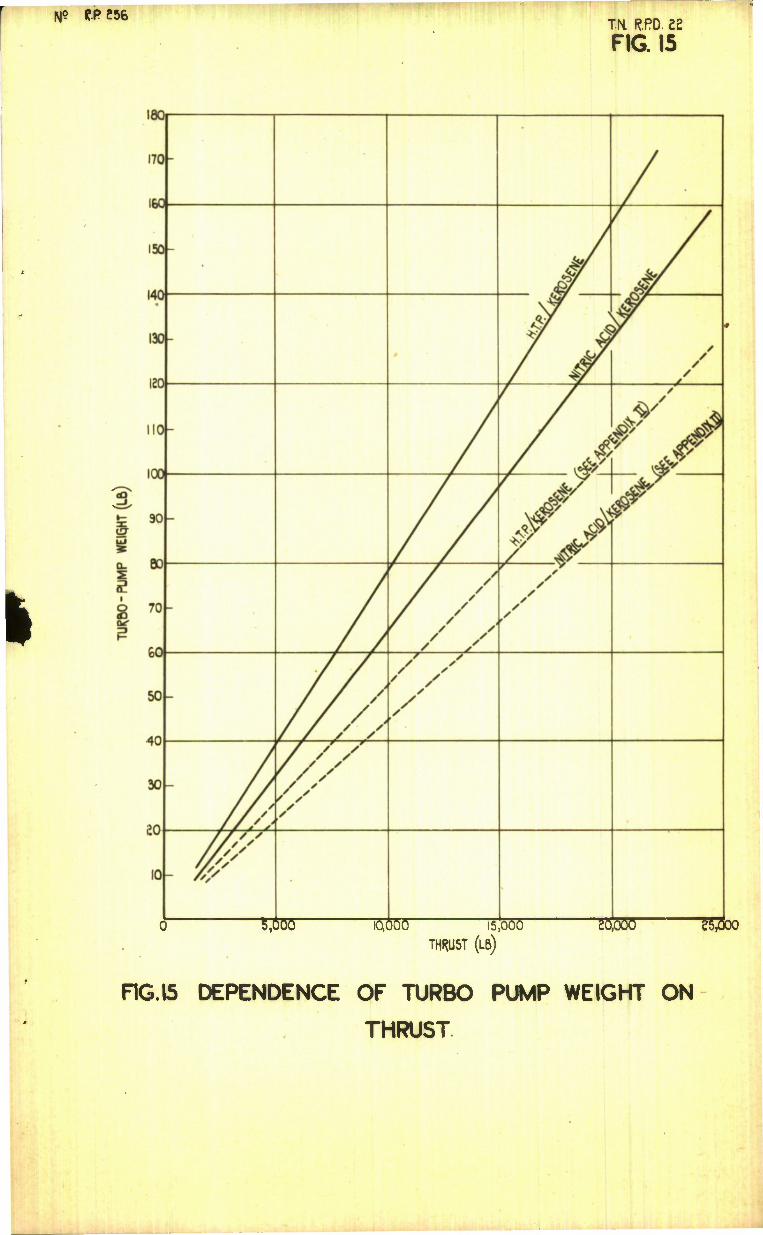
It will be noted that the overall weight for a given propellant mass flow mainly depends upon the rotational speed which is fixed by conditions in the pump with the largest throughput normally the oxidant pump. The higher the oxidant density and the less the oxidant throughput, the higher is the rotational speed and hence the smaller are the dimen- sions and weight. This can be illustrated by considering turbo-pumps required for the same rocket motor performance, but using different oxidants entailing different fuel/oxidant mixture ratios. Pig. 15 shows the relationship between the weight of the turbo-pump and the motor thrust for the combinations HTPAGr°sene and Nitric acid/kerosene. In both cases a specific impulse of 200 seconds has been assumed and mixture ratios of 11/I and 5/1 respectively, but because of the superior oxidant density characteristic and the small oxidant throughput of nitric acid/ kerosene the pump unit is 18$ lighter.
A type of turbo-pump whose rotational speed is much higher than that indicated by calculation from paragraph 2.1, is described in Appendix II. The weight of such a pump is consequently considerably reduced.
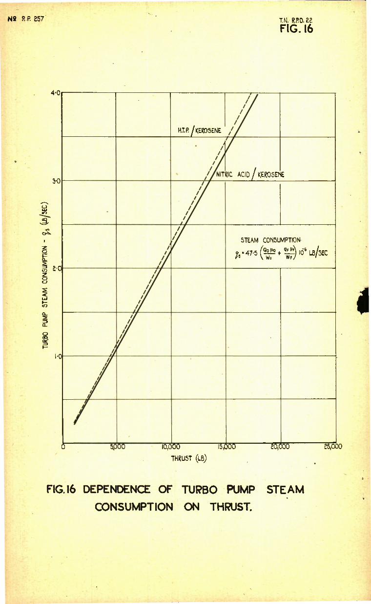
5 An estimation of turbo-pump steam consumption
It is rather difficult to obtain an accurate estimate of the steam consumption of a turbo-pump, but it is desirable to have an idea at least of what it might be in order that the designer may obtain an estimate of the amount of extra propellant (e.g. hydrogen peroxide) he will require to drive the turbo-pump.
Consider the overall efficiency of a turbo-pump.
T, H.P. Output of pumps H.P. Input of steam to turbine
Qp The H.P. output of each pump =
The H.P. available in the steam is given by
% JxHeat drop available x flow rate of steam in lb/sec
550
2.54 Hr qs where Hr is the heat drop in CHU/lb and qa. is steam flow rate lb/sec.
The heat drop can be obtained from the entropy diagram for hydrogen peroxide steam. The steam pressure ratio and exhaust temperature will affect the heat drop, but as an approximation, it is \ 50 OHU/lb over a range of preasure ratio 20 to 25 at an exhaust temperature of 375°K.
11 -
Technical Note No. R.P.D. 22
Q0Po QpPp] ITT- +
n 2.54 x 150 xq„ x 550
or
4.75 Is
Q0P0 QFPF + w. % ?
x 10 -6 (17)
Representative figures for existing turbo-pumps are given in the following Table I.
TABLE I
Steam Consumption of Turbo-pump
Turbo-pump Type of Turbine
Number of Stages
Steam Temp.°C Steam Cons, (lb/sec)
Overall Eff. %
Beta I Bucket One press One velocity
HTP 450 O.625 8
109-509 Normal One pressure (steam rever- sed back through blade£
HTP 450 1.0 12.5
A4(V.2) Normal One pressure { HTP Two Velocity
450 Approx. 5.8
15.5
As far as increasing the efficiency is concerned the Beta I turbo- pump has not been fully developed yet, but it is felt that 10% can be achieved.
If this figure of 10% overall efficiency is assumed when consider- ing the steam consumption of a turbo-pump in a proposed fuel supply system for a rocket motor, a good approximation will be obtained as follows :•-
47.5 Q0P0 QPPP
w0 ~^r 1.0"6 lb/sec (18)
Pig.16 shows the variation of steam consumption with rocket motor thrust, for the two fuel/oxidant combinations considered in paragraph 4.
6 Conclusions
This note indicates methods by which the designer of a rocket motor can obtain the weight, dimensions and steam consumption of a possible turbo-pump for that motor. The estimates are rather conservative and are based on present knowledge, but it.is pointed out that with improve- ments in both turbine and pump design the calculated figures can be reduced. Appendix II shows a method of reducing turbo-pump weight. The use of idling shroud pumps will also make a great improvement in overall efficiency of the turbo-pump. If, therefore, this note indicates that there is not a great difference between a certain pressurized system and a turbo-pump system for the same duty, the designer is recommended to investigate the turbo-pump design in more detail.
- 12 -
Technical Note No. R.P.D. 22
REFERENCES
No. Author
1 W.H. Bond
A.D. Baxter
Title^ etc.
An assessment of Expulsion Systems for R.T.V.2. Technical Note No. R.P.D.20.
High Pressure Pumps for Rocket PropeHants. Technical Note No. R.P.D.12.
Attached: -
Drwg. Nos. R.P. 248 to 258
Advance Distribution:-
M.O.S.
Chief Scientist P/DSR(A) ADSR (Gen) D Eng RD DGWRD ADGWRD (R & D) GW3 (Cdr. Ashworth) P/DTD(A)
R.A.E.
Director DDRAE(W) Supersonics Division Guided Weapons Chemistry Department S.M.E. Department Library
- 13 -
Technical Note No. R.P.D. 22
•APPENDIX I
List of Symbols
v - velocity of propellant at pump inlet - ft/sec
p - pump delivery pressure - lb/sq ft
Q - pump delivery - lb/sec
q.3 - steam flow rate - lb/sec
W - propellant density - lb/cu ft
U - peripheral velocity at outer radius of impeller - ft/sec
u - peripheral velocity at inner radius of impeller - ft/sec
n - rotational speed - revolutions per sec
R - pump impeller radius - ft
Dp - pump overall diameter - ft
r - pump inlet radius - ft
b - width of impeller blade at root - ft
RIJ - turbine rotor radius - ft
Dj - turbine overall diameter - ft
D - diameter of shaft - ft
Dp - diameter of projectile or fuselage - ft
L - total length of turbo-pump - ft
&j\ - width of turbine wheel - ft
&• - axial length of bearings - ft
6p - axial length of pump - ft
*s - axial length of fluid seals - ft
w_ - weight of pump - lb
Wj - weight of pump impeller - lb
WR - weight of turbine rotor and shaft - lb
wg - weight of turbine and bearing casing - lb
Wm - total weight of turbine - lb
p - turbine rotor and shaft material density - lb/cu ft
Pc - turbine casing material density - lb/cu ft
% - overall efficiency of turbo-pump
Ex - horse power available in steam
- 14 -
Technical Note No. R.P.D. 22
APPENDIX II
Means for Reduction of Turbo-pump Weight
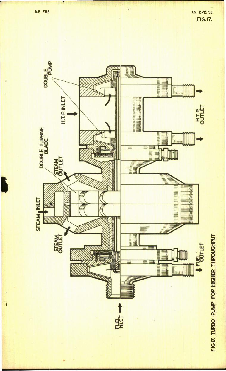
If the rotational speed of a turbo-pump can be increased and other factors such as pressure, flow rates, etc., remain the same, the overall diameter can be reduced. In order to keep the impeller blade length at a reasonable figure the inlet diameters also have to be decreased, but the reduction in size is limited by the dependence on the velocity of flow through the inlet, which should not exceed 10 ft/sec as indicated in paragraph 2.1. This is applicable to the oxidant pump since it always has the greatest delivery. If the inlet were divided into two branches either two impellers in one pump are used or one wider impeller with an entry both sides is used, then much smaller impeller diameters and consequently higher speeds could be utilised. A turbo- pump with the former arrangement of oxidant pump is shown in Pig.17. This pump would be slightly heavier and run at the same speed as the pump shown in Pig. 1, but it would deliver twice the quantity of prope Hants.
To obtain the rotational speed of such a pump the quantity Q in equation (3) can be halved, so that the speed would be y2~ times that of the normal type of pump with the same delivery.
The various weights can then be calculated as indicated before, with the exception that the weight of the oxidant pump should be doubled, to allow for the extra complications. The length will not be muoh affected.
Difficulties may be encountered in designing a small diameter turbine for high powers, but it should be possible to use either two turbine wheels on one shaft, or if using a bucket turbine utilizing the double bucket as shown in Pig. 15.
- 15 -
R.R 248 T.N. R.PD. ££
F1GS.I&2
FUEL •NLE.T FUEL
STEAM INLET
*ma HTP INLET
FIG.I . DIAGRAM OF TURBO PUMP
FIG, a. HIGH FLOW RATE OPEN IMPELLER PUMP
RP. £49 TN. f?.RD. ee
FIG5.384
OXIDANT PUMP
T OUTER CASING
D 0
FLUID SEALS
r INNER CASING
IMPELLER
TURBINE WHEEL
FUEL PUMP
D INNER CASING
OUTER CASING
IMPELLER
TURBINE CASING
FIG.3. TURBO PUMP. EXPLODED VIEW SHOWING COMPONENTS
INLET
FIG.4-.DIAGRAM OF OPEN IMPELLER PUMP
N9 f?R 250 TN. iR0.es FIGS.5 & 6
FIG.5 ESTIMATION OF TURBO-PUMP ROTATIONAL SPEED (PUMPS OF LOW THROUGHPUT)
FIG6 ESTIMATION OF TURBO PUMP ROTATIONAL SPEED (PUMPS OF HIQH THROUGHPUT)

N8 R.P. 251 T.N. R.RD. 22
FIG. 7
FIG. 7 DEPENDENCE OF IMPELLER RADIUS ON
X AND Y
H°- IF 252 TN. R.PD. £2
FIGS. 8 & 9
0'2 0-3 , v 0-4 IMPELLER I^OiUS K {ft)
0-5 0-6
FIG. 8 DEPENDENCE OF PUMP CASING WEIGHT ON MPELLER RADIUS.
(FO$ THI?0UqHPUT5 BELOW 10 LB/5EC.)
100
75
2
s Q.
£ 25
FIGS. 9
Y«oa/^
V480 *Y
WHEKE Y-J9/yW
Y'0-4/
Y--0^^^
Y-0^
Y»0j_^.—•
0-2 0-3 0-4 IMPELLER RADIUS R [jt)
0-5 0-6
DEPENDENCE OF PUMP CASING WEIGHT ON IMPELLER RADIUS. (FOS TH*0UQHPUT5 ABOVE I0LB/5EC)
N9 RP 253 TN. R.RD.22
FIG IO
0
7 Y-oy
WI«484R*Y
&
Y-0 4/
l
5
4
LU
3 Y-0^/
*C
I 5?
3 O Y-0£x^
UJ
2
1
•Y-0^^
( gZ^
c )•! 0 I 02
*•(#)
FIG.IO DEPENDENCE OF ALUMINIUM ALLOY IMPELLER
WEIGHT ON IMPELLER RADIUS.
N? _R_P 254 T.N. R.RD. 22
FIGS.II & 12
FIG 11. TYPICAL TURBIME AND CASING
"Too 5oo" n (REV. PER SEC)
GOO
r T 10 25 ir •sr —B *T~ REV/PER MIN X 10 3
FIGI2 DEPENDENCE OF TURBINE WEIGHT ON ROTATIONAL SPEED
N9 R.R 255
<* 2
5
T.H. I?.PD. 22
FIGS. 13 & 14
DF-/DT«+ L*
FIG. 13. INSTALLATION OF A TUPBO PUMP IN A PPOJECTILE OP FUSELAGE
3#5C"
ISTKIC ACID/KEROSENE
THRU5T (LB)
eQooo 15000
FIG. 14 DEPENDENCE OF MINIMUM PROJECTILE DIAMETER
ON THRUST.
N° tP ?36 IN. R.RD. 22
FIG. 15
I
•573TO 10,000 15,000
THKUST (LB)
TOE 517500
FIG.I5 DEPENDENCE OF TURBO PUMP WEIGHT ON
THRUST
Nfi R.R 857 T.N. R.RD. 22
FIG. 16
4-0
3-0
CO
o=»-
o
1/3
< t-
§
£-0
1-0
H.TR/<£lg)5ENE
ACID/<ER05EN£
STEAM CONSUMPTION-
*•«•(&*#* "fr*
ioOT WS" THRUST (LB)
20,000 25,000
FIG. 16 DEPENDEiNCE OF TUPBO PUMP STEAM CONSUMPTION ON THRUST.
R.P. £58 TN. R.PD. E2
FIG.I7
t 5
u.
[dstl] MM MM
Information Centre Knowledge S, i vu es [dstl] forum Down. Salishun Wilts SP4 O.IQ Tel: 01980-613^53 f-cixOI9tiO-6139W
Defense Technical Information Center (DTIC) 8725 John J. Kingman Road, Suit 0944 Fort Belvoir, VA 22060-6218 U.S.A.
AD#: Date of Search: 20 February 2007
Record Summary: Title: Method of calculating weight and dimensions of a turbo pump for rocket propellants Covering dates 1949 Availability Open Document, Open Description, Normal Closure before FOI Act: 30 years Former reference (Department) TN RPD 22 Held by The National Archives, Kew
This document is now available at the National Archives, Kew, Surrey, United Kingdom.
DTIC has checked the National Archives Catalogue website (http://www.nationalarchives.gov.uk) and found the document is available and releasable to the public.
Access to UK public records is governed by statute, namely the Public Records Act, 1958, and the Public Records Act, 1967. The document has been released under the 30 year rule. (The vast majority of records selected for permanent preservation are made available to the public when they are 30 years old. This is commonly referred to as the 30 year rule and was established by the Public Records Act of 1967).
This document may be treated as UNLIMITED.