Embed Size (px)
Citation preview
TOF SIMS Procedure
TOF SIMS Lab
AIF NCSU
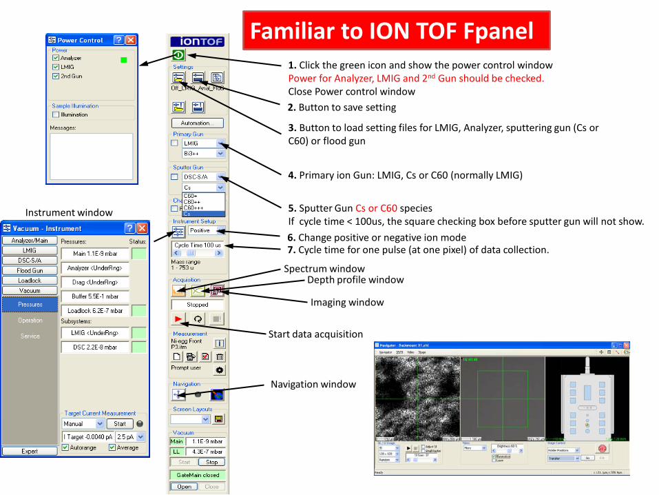
1. Click the green icon and show the power control windowPower for Analyzer, LMIG and 2nd Gun should be checked.Close Power control window
Familiar to ION TOF Fpanel
4. Primary ion Gun: LMIG, Cs or C60 (normally LMIG)
5. Sputter Gun Cs or C60 speciesIf cycle time < 100us, the square checking box before sputter gun will not show.
6. Change positive or negative ion mode
Spectrum windowDepth profile window
Imaging window
Start data acquisition
Navigation window
3. Button to load setting files for LMIG, Analyzer, sputtering gun (Cs or C60) or flood gun
2. Button to save setting
7. Cycle time for one pulse (at one pixel) of data collection.
Instrument window
Daily procedure:1. Record pressure2. Start LMIG source3. Data acquisition4. Shut down5. Data interpretation
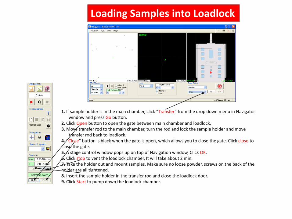
Loading Samples into Loadlock
1. If sample holder is in the main chamber, click “Transfer” from the drop down menu in Navigator window and press Go button.
2. Click Open button to open the gate between main chamber and loadlock. 3. Move transfer rod to the main chamber, turn the rod and lock the sample holder and move
transfer rod back to loadlock.4. “Close” button is black when the gate is open, which allows you to close the gate. Click close to close the gate. 5. A stage control window pops up on top of Navigation window, Click OK.6. Click stop to vent the loadlock chamber. It will take about 2 min.7. Take the holder out and mount samples. Make sure no loose powder, screws on the back of the holder are all tightened.8. Insert the sample holder in the transfer rod and close the loadlock door.9. Click Start to pump down the loadlock chamber.
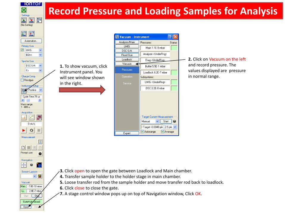
1. To show vacuum, clickInstrument panel. You will see window shown in the right.
2. Click on Vacuum on the left and record pressure. The values displayed are pressure in normal range.
Record Pressure and Loading Samples for Analysis
3. Click open to open the gate between Loadlock and Main chamber.4. Transfer sample holder to the holder stage in main chamber.5. Loose transfer rod from the sample holder and move transfer rod back to loadlock. 6. Click close to close the gate. 7. A stage control window pops up on top of Navigation window, Click OK.
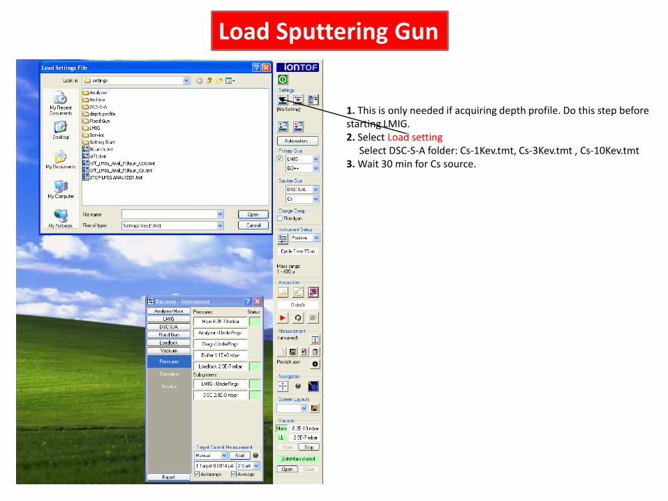
1. This is only needed if acquiring depth profile. Do this step before starting LMIG.2. Select Load setting
Select DSC-S-A folder: Cs-1Kev.tmt, Cs-3Kev.tmt , Cs-10Kev.tmt3. Wait 30 min for Cs source.
Load Sputtering Gun
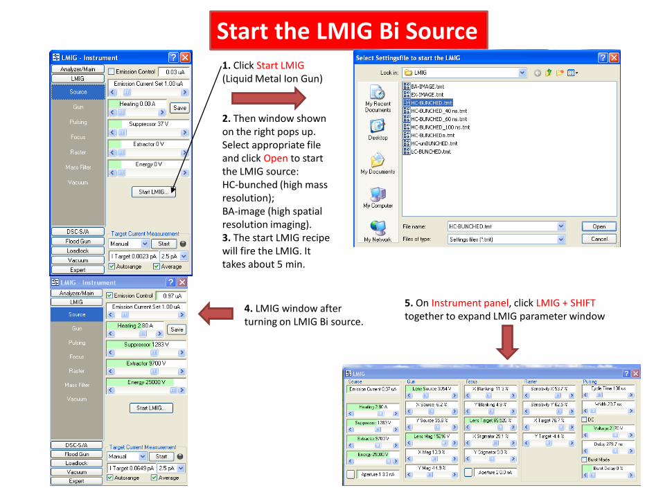
4. LMIG window after turning on LMIG Bi source.
Start the LMIG Bi Source1. Click Start LMIG (Liquid Metal Ion Gun)
2. Then window shown on the right pops up. Select appropriate file and click Open to start the LMIG source: HC-bunched (high mass resolution); BA-image (high spatial resolution imaging).3. The start LMIG recipe will fire the LMIG. It takes about 5 min.
5. On Instrument panel, click LMIG + SHIFT together to expand LMIG parameter window
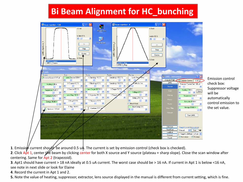
1. Emission current should be around 0.5 uA. The current is set by emission control (check box is checked).2. Click Apt 1, center the beam by clicking center for both X source and Y source (plateau + sharp slope). Close the scan window after centering. Same for Apt 2 (trapezoid). 3. Apt1 should have current > 18 nA ideally at 0.5 uA current. The worst case should be > 16 nA. If current in Apt 1 is below <16 nA, see note in next slide or look for Elaine4. Record the current in Apt 1 and 2. 5. Note the value of heating, suppressor, extractor, lens source displayed in the manual is different from current setting, which is fine.
Bi Beam Alignment for HC_bunching
Emission control check box: Suppressor voltage will be automatically control emission to the set value.
If current in Apt 1 is low <16 nA, try following steps:1. Uncheck emission control in LMIG-Instrument window 2. Drag Suppressor bar to maximum voltage 2000V. Normally you will see the emission current increase to its maximal current 12.5 µA. The current in Apt 1 is 62.5 nA. If you do not see the current goes to its maximum, increase Extractor little by little until the maximal current is reached.3. Decrease Suppressor voltage until the current is around 1 µA.4. Check the Apt 1, Apt 2 current and center the beam.5. If you change the Extractor voltage, you also need to change the lens source voltage. The rule is: higher the extractor, higher the lens source.6. Adjust lens source with Apt 1 scan window open. Adjust lens source until a plateau + sharp slope is obtained.7. If this still does not solve the problem, please contact Elaine for further assistance.
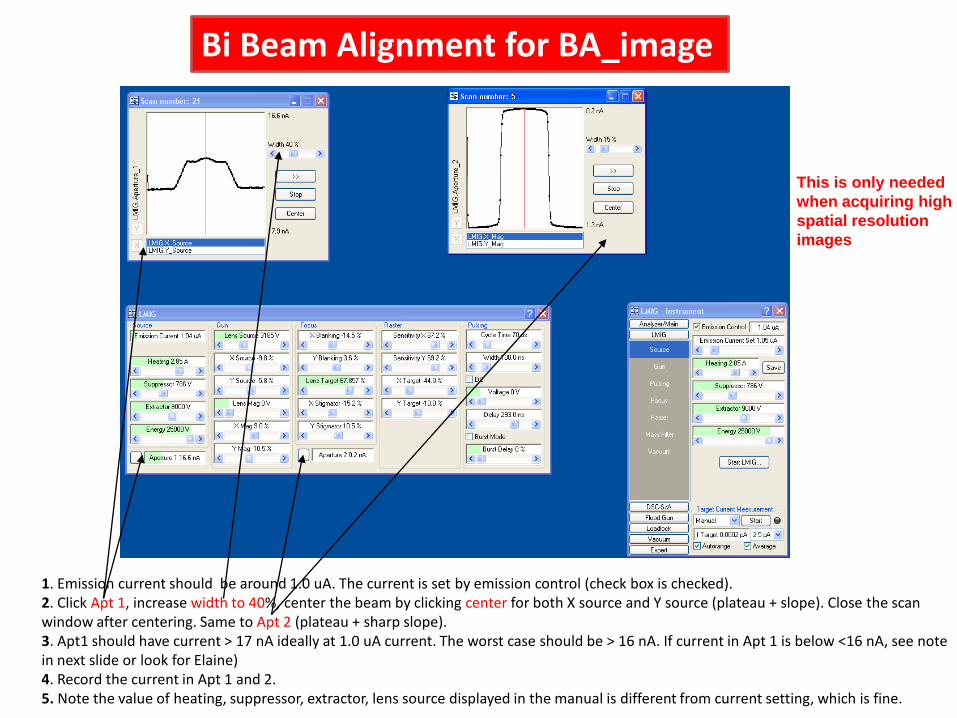
1. Emission current should be around 1.0 uA. The current is set by emission control (check box is checked).2. Click Apt 1, increase width to 40%, center the beam by clicking center for both X source and Y source (plateau + slope). Close the scan window after centering. Same to Apt 2 (plateau + sharp slope). 3. Apt1 should have current > 17 nA ideally at 1.0 uA current. The worst case should be > 16 nA. If current in Apt 1 is below <16 nA, see note in next slide or look for Elaine)4. Record the current in Apt 1 and 2. 5. Note the value of heating, suppressor, extractor, lens source displayed in the manual is different from current setting, which is fine.
Bi Beam Alignment for BA_image
This is only needed when acquiring high spatial resolution images
Bi Beam Focusing for BA_image
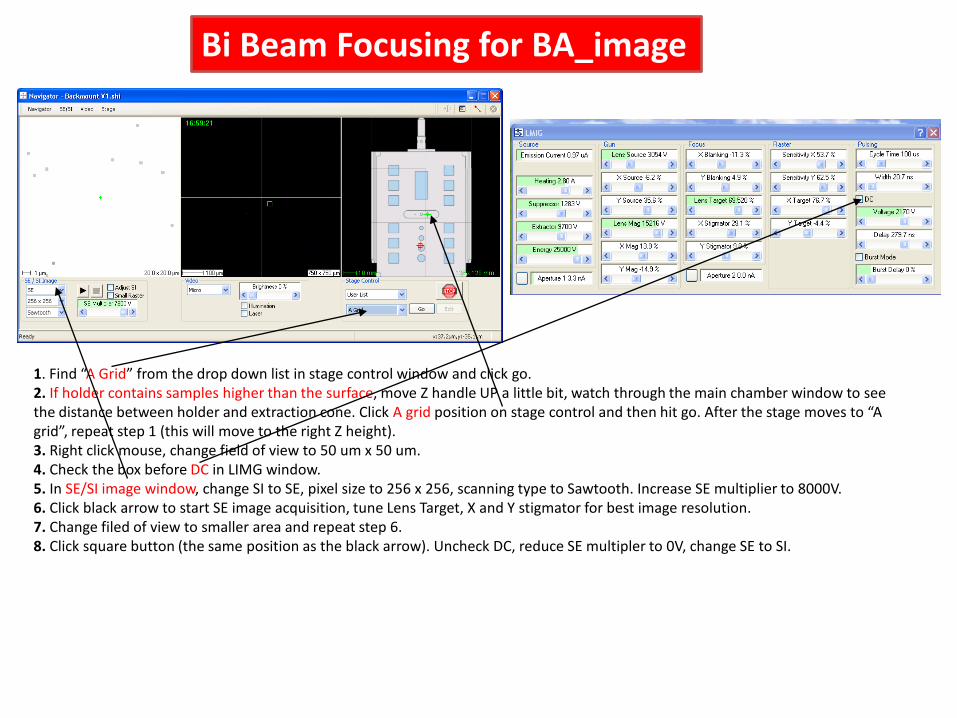
1. Find “A Grid” from the drop down list in stage control window and click go. 2. If holder contains samples higher than the surface, move Z handle UP a little bit, watch through the main chamber window to see the distance between holder and extraction cone. Click A grid position on stage control and then hit go. After the stage moves to “A grid”, repeat step 1 (this will move to the right Z height). 3. Right click mouse, change field of view to 50 um x 50 um. 4. Check the box before DC in LIMG window.5. In SE/SI image window, change SI to SE, pixel size to 256 x 256, scanning type to Sawtooth. Increase SE multiplier to 8000V. 6. Click black arrow to start SE image acquisition, tune Lens Target, X and Y stigmator for best image resolution.7. Change filed of view to smaller area and repeat step 6.8. Click square button (the same position as the black arrow). Uncheck DC, reduce SE multipler to 0V, change SE to SI.
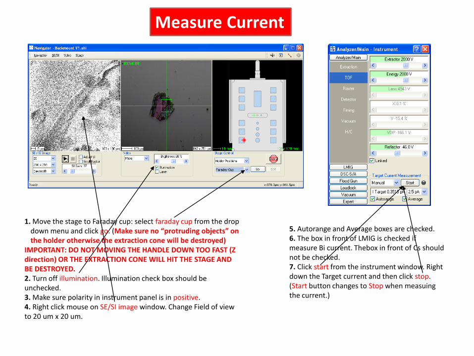
1. Move the stage to Faraday cup: select faraday cup from the drop down menu and click go. (Make sure no “protruding objects” on the holder otherwise the extraction cone will be destroyed)
IMPORTANT: DO NOT MOVING THE HANDLE DOWN TOO FAST (Z direction) OR THE EXTRACTION CONE WILL HIT THE STAGE AND BE DESTROYED.2. Turn off illumination. Illumination check box should be unchecked.3. Make sure polarity in instrument panel is in positive. 4. Right click mouse on SE/SI image window. Change Field of view to 20 um x 20 um.
Measure Current
5. Autorange and Average boxes are checked.6. The box in front of LMIG is checked if measure Bi current. Thebox in front of Cs should not be checked.7. Click start from the instrument window. Right down the Target current and then click stop. (Start button changes to Stop when measuing the current.)
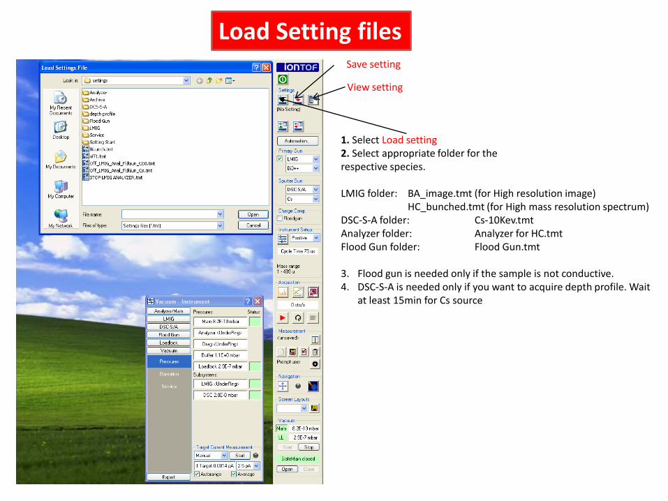
1. Select Load setting2. Select appropriate folder for the respective species.
LMIG folder: BA_image.tmt (for High resolution image)HC_bunched.tmt (for High mass resolution spectrum)
DSC-S-A folder: Cs-10Kev.tmtAnalyzer folder: Analyzer for HC.tmtFlood Gun folder: Flood Gun.tmt
3. Flood gun is needed only if the sample is not conductive.4. DSC-S-A is needed only if you want to acquire depth profile. Wait
at least 15min for Cs source
View setting
Save setting
Load Setting files
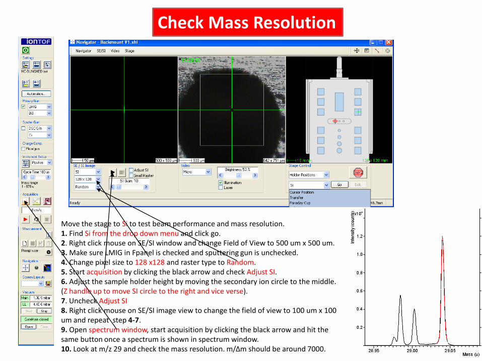
Move the stage to Si to test beam performance and mass resolution.1. Find Si from the drop down menu and click go. 2. Right click mouse on SE/SI window and change Field of View to 500 um x 500 um.3. Make sure LMIG in Fpanel is checked and sputtering gun is unchecked.4. Change pixel size to 128 x128 and raster type to Random.5. Start acquisition by clicking the black arrow and check Adjust SI. 6. Adjust the sample holder height by moving the secondary ion circle to the middle. (Z handle up to move SI circle to the right and vice verse).7. Uncheck Adjust SI8. Right click mouse on SE/SI image view to change the field of view to 100 um x 100 um and repeat step 4-7.9. Open spectrum window, start acquisition by clicking the black arrow and hit the same button once a spectrum is shown in spectrum window.10. Look at m/z 29 and check the mass resolution. m/Δm should be around 7000.
Check Mass Resolution
Mass (u)10 20 30 40 50 60 70 80 90
5x10
0.2
0.4
0.6
0.8Inte
nsity
(cou
nts)
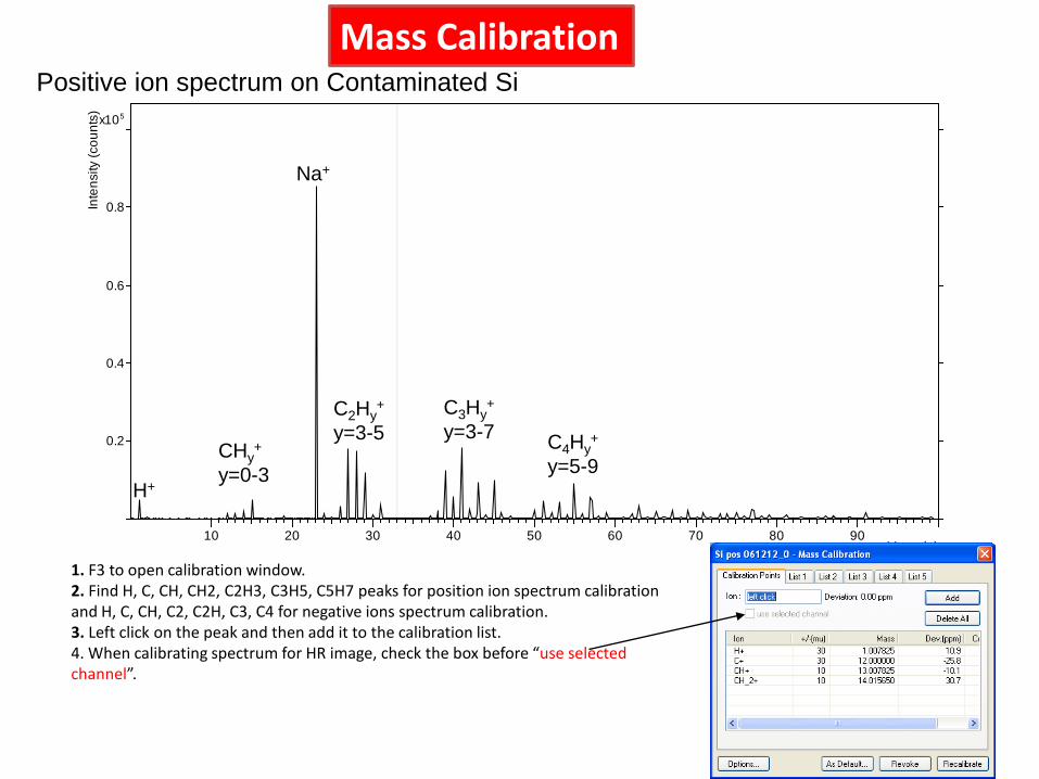
1. F3 to open calibration window.2. Find H, C, CH, CH2, C2H3, C3H5, C5H7 peaks for position ion spectrum calibration and H, C, CH, C2, C2H, C3, C4 for negative ions spectrum calibration.3. Left click on the peak and then add it to the calibration list.4. When calibrating spectrum for HR image, check the box before “use selected channel”.
H+
CHy+
y=0-3
Na+
C2Hy+
y=3-5C3Hy
+
y=3-7 C4Hy+
y=5-9
Positive ion spectrum on Contaminated SiMass Calibration
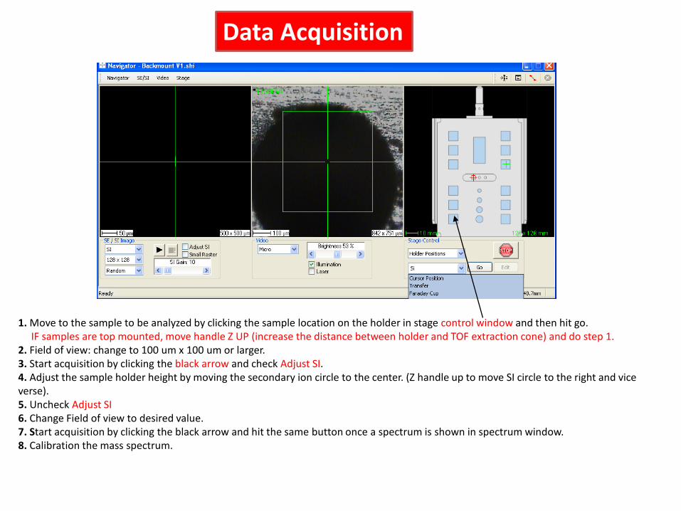
1. Move to the sample to be analyzed by clicking the sample location on the holder in stage control window and then hit go. IF samples are top mounted, move handle Z UP (increase the distance between holder and TOF extraction cone) and do step 1.
2. Field of view: change to 100 um x 100 um or larger.3. Start acquisition by clicking the black arrow and check Adjust SI. 4. Adjust the sample holder height by moving the secondary ion circle to the center. (Z handle up to move SI circle to the right and vice verse).5. Uncheck Adjust SI6. Change Field of view to desired value.7. Start acquisition by clicking the black arrow and hit the same button once a spectrum is shown in spectrum window.8. Calibration the mass spectrum.
Data Acquisition
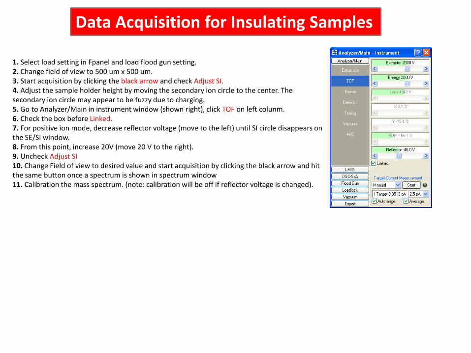
1. Select load setting in Fpanel and load flood gun setting.2. Change field of view to 500 um x 500 um.3. Start acquisition by clicking the black arrow and check Adjust SI. 4. Adjust the sample holder height by moving the secondary ion circle to the center. The secondary ion circle may appear to be fuzzy due to charging. 5. Go to Analyzer/Main in instrument window (shown right), click TOF on left colunm.6. Check the box before Linked. 7. For positive ion mode, decrease reflector voltage (move to the left) until SI circle disappears on the SE/SI window. 8. From this point, increase 20V (move 20 V to the right). 9. Uncheck Adjust SI10. Change Field of view to desired value and start acquisition by clicking the black arrow and hit the same button once a spectrum is shown in spectrum window11. Calibration the mass spectrum. (note: calibration will be off if reflector voltage is changed).
Data Acquisition for Insulating Samples
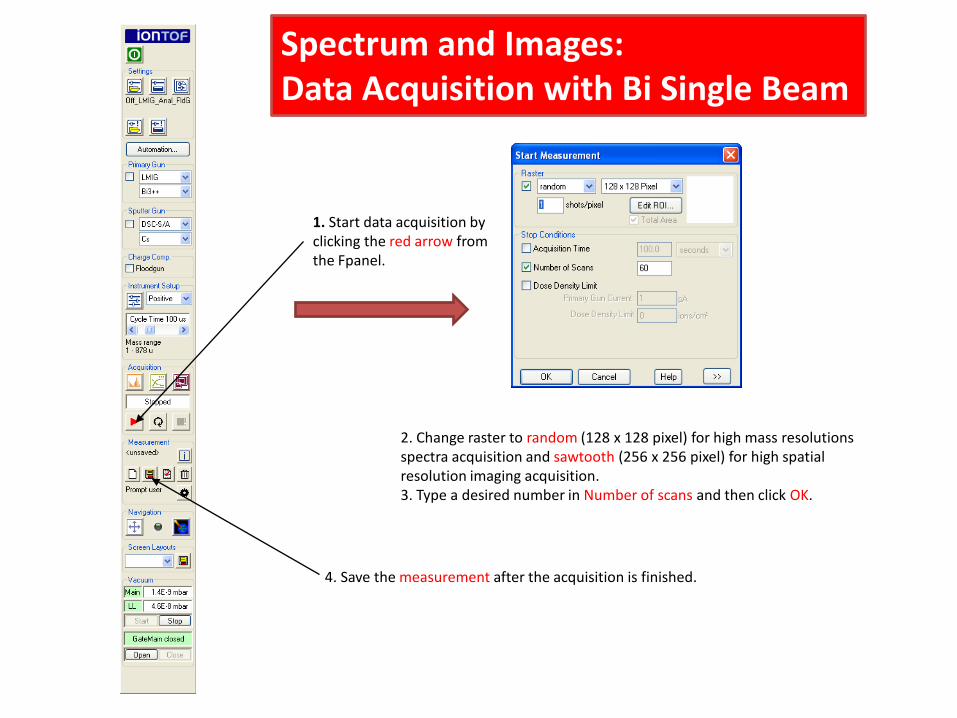
4. Save the measurement after the acquisition is finished.
Spectrum and Images:Data Acquisition with Bi Single Beam
1. Start data acquisition by clicking the red arrow from the Fpanel.
2. Change raster to random (128 x 128 pixel) for high mass resolutions spectra acquisition and sawtooth (256 x 256 pixel) for high spatial resolution imaging acquisition.3. Type a desired number in Number of scans and then click OK.
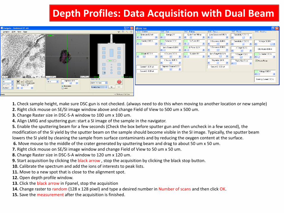
Depth Profiles: Data Acquisition with Dual Beam
1. Check sample height, make sure DSC gun is not checked. (always need to do this when moving to another location or new sample)2. Right click mouse on SE/SI image window above and change Field of View to 500 um x 500 um.3. Change Raster size in DSC-S-A window to 100 um x 100 um.4. Align LMIG and sputtering gun: start a SI image of the sample in the navigator. 5. Enable the sputtering beam for a few seconds (Check the box before sputter gun and then uncheck in a few second), the modification of the SI yield by the sputter beam on the sample should become visible in the SI image. Typically, the sputter beam lowers the SI yield by cleaning the sample from surface contaminants and by reducing the oxygen content at the surface. 6. Move mouse to the middle of the crater generated by sputtering beam and drag to about 50 um x 50 um.7. Right click mouse on SE/SI image window and change Field of View to 50 um x 50 um.8. Change Raster size in DSC-S-A window to 120 um x 120 um.9. Start acquisition by clicking the black arrow , stop the acquisition by clicking the black stop button.10. Calibrate the spectrum and add the ions of interests to peak lists.11. Move to a new spot that is close to the alignment spot.12. Open depth profile window.13. Click the black arrow in Fpanel, stop the acquisition 14. Change raster to random (128 x 128 pixel) and type a desired number in Number of scans and then click OK.15. Save the measurement after the acquisition is finished.
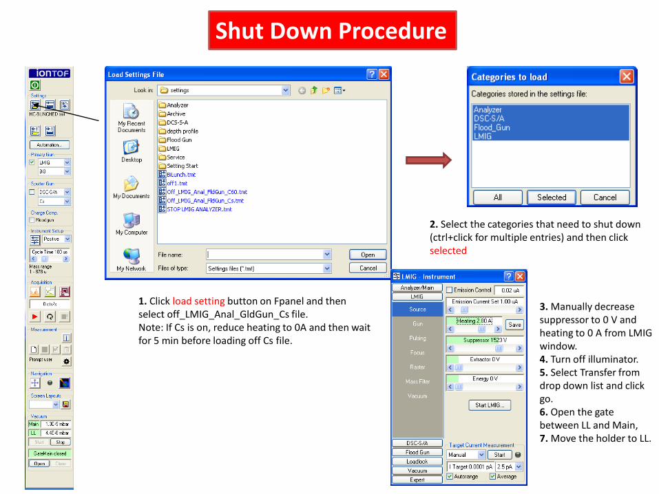
1. Click load setting button on Fpanel and then select off_LMIG_Anal_GldGun_Cs file.Note: If Cs is on, reduce heating to 0A and then wait for 5 min before loading off Cs file.
Shut Down Procedure
2. Select the categories that need to shut down (ctrl+click for multiple entries) and then click selected
3. Manually decrease suppressor to 0 V and heating to 0 A from LMIG window.4. Turn off illuminator.5. Select Transfer from drop down list and click go.6. Open the gate between LL and Main,7. Move the holder to LL.


![[特集]有機エレクトロニクス (2)GCIB-TOF-SIMSに …...GCIB-TOF-SIMS分析を行った。TOF-SIMS測定には、 ION-TOF社製TOF.SIMS.5を用い、GCIB(エッチング](https://img.pdfslide.net/doc/110x75/5f2c80fe25b37a65f137eca3/ceoeffff-2igcib-tof-sims-gcib-tof-simseoetof-sims.jpg)


![Paul Ahern - Time of Flight Secondary Ion Mass Spectroscopy [ToF-SIMS] theory & practice](https://img.pdfslide.net/doc/110x75/55504121b4c905b2788b4981/paul-ahern-time-of-flight-secondary-ion-mass-spectroscopy-tof-sims-theory-practice.jpg)