Embed Size (px)
Citation preview
Tool Path Generation Method of Complex Surface 5-axis Machining
Huiying Li and Liangji Chen* School of Mechatronics Engineering, Zhengzhou University of Aeronautics, China
*Corresponding author Abstract—To enhance 5-axis CNC machining precision of complex surfaces with a ball-end cutter, the generation method of cutter contacting (CC) paths is presented in this paper. By means of curvature circle, the feeding length was calculated within allowable error. The step-over in the perpendicular direction of feeding one, was figured out according to the permissible remnant cusps. With the local curvature and the machining error, the step-size was calculated to get the parameter of the next cutter-contacting point. The corresponding spline path of tool center points including knot vector and controlling points was obtained from the cutter contacting points.
Keywords-complex surface; tool path; ball-end cutter; 5-axis machining
I. INTRODUCTION When the CAD systems design 3-D model production that
has the character of free surface, it usually takes it as a form of Non-Uniform Rational B-Spline(NURBS)[1].When processing this production in the computer numerical control (CNC) machine tool, it must calculate the tool path of free surface which is expressed with NURBS. The current CNC system generally has the function of interpolation of line or arc, so they can only execute the motion instruction of line or arc. In order to process free surface, tool path is generated by some straight segments or arc segments, and then it will generate the corresponding CNC codes. The way of approximate machining has the following shortcomings: (1) increase approximated segments to improve machining accuracy, and it may lead to large CNC program and heavy system data load; (2) it needs acceleration and deceleration in the interpolation and it will lead to poor consistency of the cutting speed. (3) the way of approximation lost the original NURBS information of surface expression, and it can lead to lower machine accuracy.
5-axis CNC machine tools are widely used in machining dies, molds, turbine blades, and aerial parts. These parts usually have complex geometry and are represented by parametric or sculptured surfaces. The NURBS method[1] is currently used for representing and designing the above surfaces in most commercial computer-aided design and manufacturing (CAD/CAM) systems. If a 5-axis CNC machine tool is applied to machining a part with complex shape, the NURBS surface model of the part is firstly obtained from CAD system and then 5-axis tool path of cutting tool is generated in CAM system. However, the above tool path generated by CAM system cannot be directly input into 5-axis CNC machine to execute accurate cutting because of local gouging between cutter and workpiece. Tikhon[2]and Cheng[3,4]had presented a surface
machining method for ball-end cutting tool, respectively. However, these ball-end cutting methods had disadvantages such as lower manufacturing efficiency and so on. The CAM system, which is of great generality, is not enough flexible to get a gouging-free tool path for a specific part. So, a special 5-axis CAM system must be easily obtained. In order to develop a CAM system for special usage, generally, the urgent task is to generating a gouging-free tool path for an arbitrary NURBS surface machining. In 5-axis surface machining, flat-end cutter, whose effective radius is enlarged when it is inclined and tilted, has been mostly used in relative researches [6-9]. In the rest of this paper, representation method of free-form surface using NURBS is introduced and a 5-axis machining method with a flat-end cutter is proposed based on the NURBS surface.
Fortunately, CNC manufacturers have already realized the above-mentioned problems, and provided the direct control function of NURBS track in their high-grade NC systems. These systems can control the tool spline paths [2~4]. However, the generation of NURBS spline path is a difficult problem, its process of internal operation is different from the current generation type of approximate tool path, and it is more difficult to get the more precise NURBS tool path.
It has a detailed discussion about the problem in this paper, and tries to find the method of free surface of NURBS process path.
II. NURBS EXPRESSION OF COMPLEX SURFACE In the Cartesian coordinate system (o-xyz), a free surface
can be expressed as the following parameter form
( , )u vS = T[ ( , ), ( , ), ( , )]x u v y u v z u v = ( , )x u v i + ( , )y u v j+ ( , )z u v k 0≤ vu, ≤1 (1)
where i,j,k respectively is the unit vector of the direction of x,y,z; u and v are the parameters. The free curved surface in the (1) can be expressed with NURBS[5]
( , )u vS =
, , , ,0 0
, , ,0 0
( ) ( )
( ) ( )
n m
s p t q s t s ts t
n m
s p t q s ts t
B u B v
B u B v
ω
ω
= =
= =
∑∑
∑∑
T
0≤ vu , ≤1 (2)
International Conference on Electrical, Mechanical and Industrial Engineering (ICEMIE 2016)
© 2016. The authors - Published by Atlantis Press 197
where ,s tT is control point; ,i jω is the corresponding weight
factor of ,s tT ; (n+1) is the number of control point of u direction and (m+1) is the number of control point of v direction; , ( )s pB u is the B-spline basis function of
u direction and , ( )t qB v is the B-spline basis function of v direction, p and q are the times.
III. GENERATION OF CUTTER CONTACTING POINT The cutter head of ball-end cutter has good adaptability
and cutting quality when milling free surface. So it is widely used in the process of CNC milling. Before getting the CNC program of ball cutter, it needs to calculate the cutter contacting point of cutter head sphere and free surface, and get the path curve of cutter contacting point.
A. Determine the Track of Original Cutter Contacting Point For the complex surface, it can select one of its’ border
curve (S(u,0),S(u,1) and S(0,v),S(1,v)) as the path of original cutter contacting point according to specific circumstance, the subsequent calculation is on the basis of the path of cutter contacting point.
It selects S(u,0) as an example in this paper and chooses S(0,0) as the first cutter contacting point.
B. Calculation of Contiguous Cutter Contacting Point On the path curve of cutter contacting point, the distance of
contiguous two cutter contacting point is just the feed step length of this cutter contacting point. Therefore, when calculating the next adjacent cutter contacting point with knowing the last cutter contacting point, it should firstly calculate the feed step length. The calculation of feed step length must be based on the allowing manufacturing error.
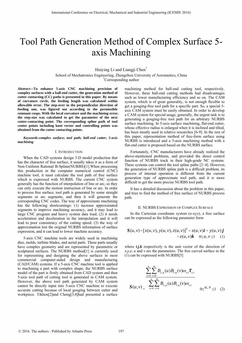
It is supposed that the current cutter contacting point is the jth cutter contacting point Ci,j on the path curve Pi of the ith cutter contacting point, and the next adjacent cutter contacting point is Ci,j + 1. As shown in Fig.1, Pi,Ci,j and Ci,j + 1 are respectively expressed as Pi=S(u,vi), Ci,j= S(uj,vi) and Ci,j+1=S(uj+1,vi)Where vi is constant between 0 and 1.
Ci, j
Pi
ρj
ε
Δw
Ci, j+1
FIGURE I. CALCULATION OF FEED STEP LENGTH
The calculation equation of Ci,j curvature which is on the curve Pi is
jρ =( )juρ
=
3
2
2
( )
( ) ( )
j i
j i j i
u ,vu
u ,v u ,vu u
∂∂
∂ ∂×
∂ ∂
S
S S
(3)
and calculate the feed step length wΔ according to the following equation
wΔ =( ) ( )2 2
2 j jρ ρ ε− − (4)
After calculating wΔ , it can calculate the parameter uj+1 of cutter contacting point Ci,j+1 according to (5)
uj+1=uj
( )j i
wu ,vu
Δ+
∂∂
S
(5)
And then it can calculate the next adjacent cutter contacting point.
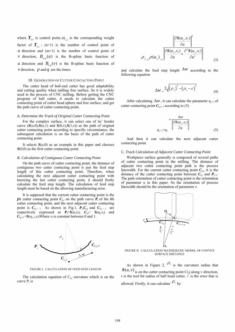
C. Track Calculation of Adjacent Cutter Contacting Point Workpiece surface generally is composed of several paths
of cutter contacting point in the milling. The distance of adjacent two cutter contacting point path is the process linewidth. For the current cutter contacting point Ci,j, it is the distance of the cutter contacting point between Ci,j and Pi+1. The path orientation of cutter contacting point is the orientation of parameter u in this paper. So the orientation of process linewidth should be the orientation of parameter v.
Ci,jε
Ci+1,j
r
ρi+
r
ρi+ε
A
B
C
FIGURE II. CALCULATION MATHEMATIC MODEL OF CONVEX
SURFACE DISTANCE
As shown in Figure 2, iρ is the curvature radius that ( , )u vS is on the cutter contacting point Ci,j along v direction,
r is the tool bit radius of ball head cutter, ε is the error that is
allowed. Firstly, it can calculate iρ by
198
iρ = ( )ivρ =
3
2
2
( )
( ) ( )
j i
j i j i
u ,vv
u ,v u ,vv v
∂∂
∂ ∂×
∂ ∂
S
S S
(6)
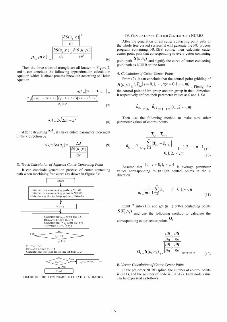
Then the three sides of triangle are all known in Figure 2, and it can conclude the following approximation calculation equation which is about process linewidth according to Helen equation.
dΔ = , 1 ,i j i j+−C C =[ ]( ) ( )22 2 ( 2 ) / 2 / 2i i
i
r r
r
ρ ε ρ ε ε ε
ρ
± + ± −
± (7)
dΔ =22 2 rε ε− (8)
After calculating dΔ , it can calculate parameter increment in the v direction by
Δvj = ( )jv uΔ = ( )j i
du ,vv
Δ∂
∂S
(9)
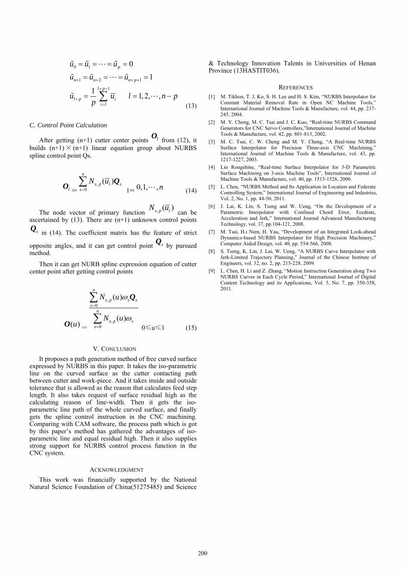
D. Track Calculation of Adjacent Cutter Contacting Point It can conclude generation process of cutter contacting
path when machining free curve (as shown in Figure 3):
Start
Initial cutter contacting path is S(u,0)Initial cutter contacting point is S(0,0)Calculating the tool-tip spline of S(u,0)
Calculating uj+1 with Eq. (5)If(uj+1>1), then uj+1=1Calculating Δvj with Eq. (7)Δv=min{Δv, Δvj }
uj+1<1
Δv=1
vi+1=vi+ΔvIf(vi+1>1), then vi+1=1Calculating the tool-tip spline of S(u,vi+1)
vi+1<1 uj=0, vi=vi+1
End
Yes
No
Yes
No
FIGURE III. THE FLOW CHART OF CC PATH GENERATION
IV. GENERATION OF CUTTER CENTER POINT NURBS After the generation of all cutter contacting point path of
the whole free curved surface, it will generate the NC process program containing NURBS spline, then calculate cutter center point path that corresponding to every cutter contacting
point path ( , )iu vS and signify the curve of cutter contacting point path as NURB spline form.
A. Calculation of Cutter Center Point From (2), it can conclude that the control point gridding of
( , )u vS is , 0,1, , ; 0,1, ,s t s n t m= =L L{ | }T. Firstly, for
the control point of 0th group and nth group in the u direction, it respectively defines their parameter values as 0 and 1. So
0,ˆ tu=0, ,ˆn tu
=1 t=0,1, 2, , mL
Then use the following method to make sure other parameter values of control points
,ˆl tu= 1,ˆl tu − +
, 1,
, 1,1
l t l tn
k t k tk
−
−=
−
−∑
T T
T T l=1, 2, , 1n −L ; t=
0,1, 2, , mL (10)
Assume that { | 0,1, , }lu l n= L is average parameter values corresponding to (n+1)th control points in the u direction
lu =,
0
1 ˆ 0,1, ,1
m
l tt
u l nm =
=+ ∑ L
(11)
Input iu into (10), and get (n+1) cutter contacting points ( , )l iu vS and use the following method to calculate the
corresponding cutter center points lO
lO = ( , )l iu vS +r ( , ) ( , )l iu v u v
u v
u v =
∂ ∂×
∂ ∂∂ ∂×∂ ∂
S S
S S
(12)
B. Vector Calculation of Cutter Center Point In the pth order NURB spline, the number of control points
is (n+1), and the number of node is (n+p+2). Each node value can be expressed as follows:
199
0 1
1 2 1
1
0
1
1 1, 2, ,
p
n n n p
l p
l p ii l
u u u
u u u
u u l n pp
+ + + +
+ −
+=
= = = =
= = = =
= = −∑
% % %L
% % %L
% L (13)
C. Control Point Calculation
After getting (n+1) cutter center points lO from (12), it builds (n+1)× (n+1) linear equation group about NURBS spline control point Qs.
lO=
,0
( )n
s p l ss
N u=∑ Q
l=0,1, , nL (14)
The node vector of primary function , ( )s p lN u can be
ascertained by (13). There are (n+1) unknown control points
sQ in (14). The coefficient matrix has the feature of strict
opposite angles, and it can get control point sQ by pursued method.
Then it can get NURB spline expression equation of cutter center point after getting control points
( )uO=
,0
,0
( )
( )
n
s p s ss
n
s p ss
N u
N u
ω
ω
=
=
∑
∑
Q
0≤u≤1 (15)
V. CONCLUSION It proposes a path generation method of free curved surface
expressed by NURBS in this paper. It takes the iso-parametric line on the curved surface as the cutter contacting path between cutter and work-piece. And it takes inside and outside tolerance that is allowed as the reason that calculates feed step length. It also takes request of surface residual high as the calculating reason of line-width. Then it gets the iso-parametric line path of the whole curved surface, and finally gets the spline control instruction in the CNC machining. Comparing with CAM software, the process path which is got by this paper’s method has gathered the advantages of iso-parametric line and equal residual high. Then it also supplies strong support for NURBS control process function in the CNC system.
ACKNOWLEDGMENT This work was financially supported by the National
Natural Science Foundation of China(51275485) and Science
& Technology Innovation Talents in Universities of Henan Province (13HASTIT036).
REFERENCES [1] M. Tikhon, T. J. Ko, S. H. Lee and H. S. Kim, “NURBS Interpolator for
Constant Material Removal Rate in Open NC Machine Tools,” International Journal of Machine Tools & Manufacture, vol. 44, pp. 237-245, 2004.
[2] M. Y. Cheng, M. C. Tsai and J. C. Kuo, “Real-time NURBS Command Generators for CNC Servo Controllers,”International Journal of Machine Tools & Manufacture, vol. 42, pp. 801-813, 2002.
[3] M. C. Tsai, C. W. Cheng and M. Y. Cheng, “A Real-time NURBS Surface Interpolator for Precision Three-axis CNC Machining,” International Journal of Machine Tools & Manufacture, vol. 43, pp. 1217-1227, 2003.
[4] Lin Rongshine, “Real-time Surface Interpolator for 3-D Parametric Surface Machining on 3-axis Machine Tools”, International Journal of Machine Tools & Manufacture, vol. 40, pp. 1513-1526, 2000.
[5] L. Chen, “NURBS Method and Its Application in Location and Federate Controlling System,” International Journal of Engineering and Industries, Vol. 2, No. 1, pp. 44-50, 2011.
[6] J. Lai, K. Lin, S. Tseng and W. Ueng, “On the Development of a Parametric Interpolator with Confined Chord Error, Feedrate, Acceleration and Jerk,” International Journal Advanced Manufacturing Technology, vol. 37, pp.104-121, 2008.
[7] M. Tsai, H.i Nien, H. Yau, “Development of an Integrated Look-ahead Dynamics-based NURBS Interpolator for High Precision Machinery,” Computer Aided Design, vol. 40, pp. 554-566, 2008.
[8] S. Tseng, K. Lin, J. Lai, W. Ueng, “A NURBS Curve Interpolator with Jerk-Limited Trajectory Planning,” Journal of the Chinese Institute of Engineers, vol. 32, no. 2, pp. 215-228, 2009.
[9] L. Chen, H. Li and Z. Zhang, “Motion Instruction Generation along Two NURBS Curves in Each Cycle Period,” International Journal of Digital Content Technology and its Applications, Vol. 5, No. 7, pp. 350-358, 2011.
200