Embed Size (px)
Citation preview

The Selection of Manufacturing Engineering Process; By Dr. Saied. M. Darwish
TOOL WEAR AND TOOL LIFE
CHAPTER FOUR :Tool Wear and Tool Life
CONTENTS
The Selection of Manufacturing Engineering Process; By Dr. Saied. M. Darwish
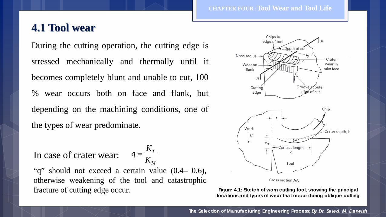
4.1 Tool wear During the cutting operation, the cutting edge is
stressed mechanically and thermally until it
becomes completely blunt and unable to cut, 100
% wear occurs both on face and flank, but
depending on the machining conditions, one of
the types of wear predominate.
CHAPTER FOUR :Tool Wear and Tool Life
Figure 4.1: Sketch of worn cutting tool, showing the principal locations and types of wear that occur during oblique cutting
In case of crater wear: M
T
KKq =
“q” should not exceed a certain value (0.4– 0.6), otherwise weakening of the tool and catastrophic fracture of cutting edge occur.
Tool Life: Wear and Failure
Tool wear is gradual process; created due to: 1- High localized stresses at the tip of the tool 2- High temperatures (especially along rake face) 3- Sliding of the chip along the rake face 4- Sliding of the tool along the newly cut workpiece surface
The rate of tool wear depends on - tool and workpiece materials - tool geometry - process parameters - cutting fluids - characteristics of the machine tool
Copyright © 2010 Pearson Education South Asia Pte Ltd
3
Tool Life: Wear and Failure
4
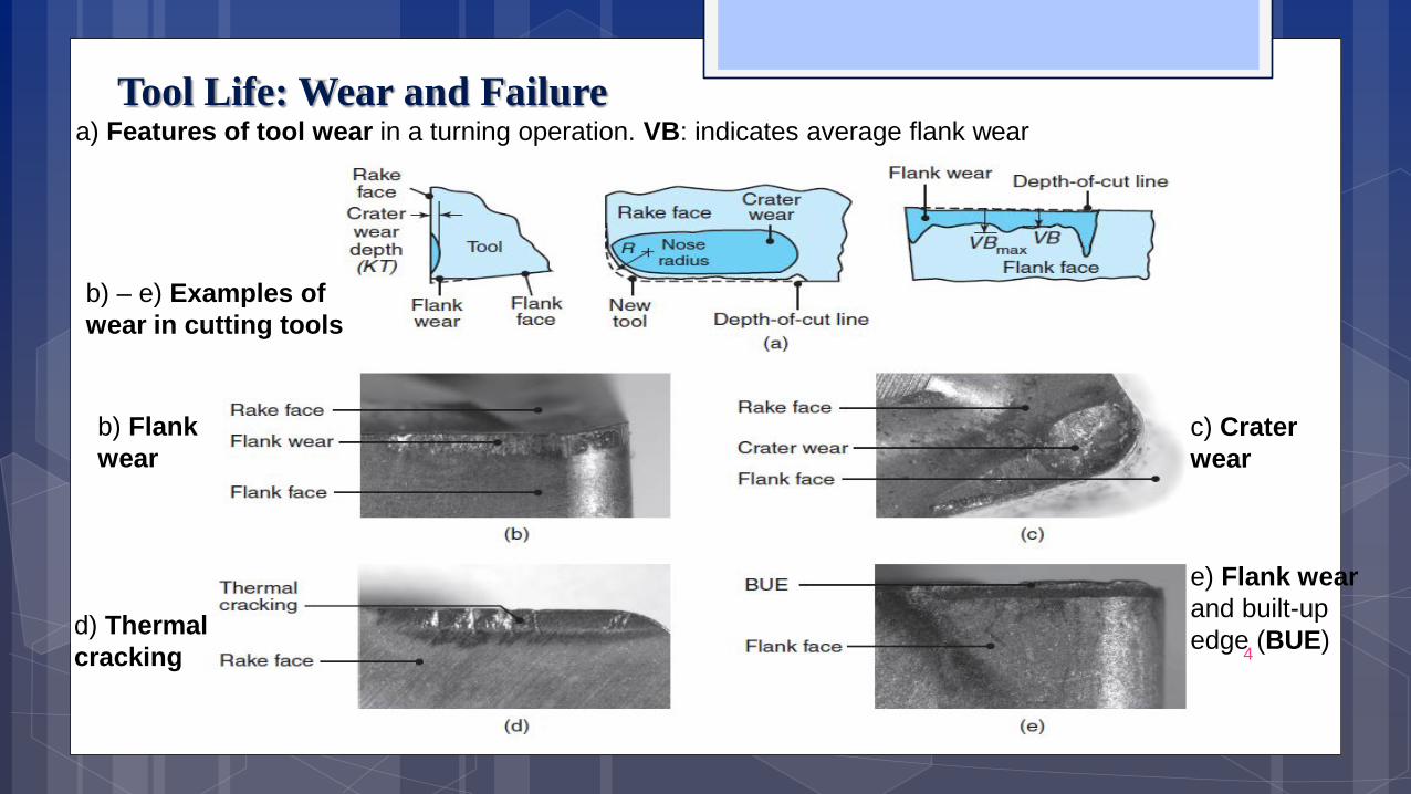
a) Features of tool wear in a turning operation. VB: indicates average flank wear
b) – e) Examples of wear in cutting tools
b) Flank wear
c) Crater wear
d) Thermal cracking
e) Flank wear and built-up edge (BUE)

Tool Life: Wear and Failure: Flank Wear
Flank wear occurs on the relief (flank) face of the tool It is due to - rubbing of the tool along machined surface (⇒ adhesive/abrasive wear) - high temperatures (adversely affecting tool-material properties) Taylor tool life equation :
Copyright © 2010 Pearson Education South Asia Pte Ltd
CVT n =V = cutting speed [m/minute] T = time [minutes] taken to develop a certain flank wear land (VB, last slide) n = an exponent that generally depends on tool material (see above) C = constant; depends on cutting conditions note, magnitude of C = cutting speed at T = 1 min (can you show how?) Also note: n, c : determined experimentally
5
The Selection of Manufacturing Engineering Process; By Dr. Saied. M. Darwish
CHAPTER FOUR :Tool Wear and Tool Life
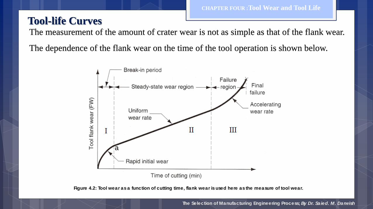
The measurement of the amount of crater wear is not as simple as that of the flank wear.
The dependence of the flank wear on the time of the tool operation is shown below.
Figure 4.2: Tool wear as a function of cutting time, flank wear is used here as the measure of tool wear.
a
Tool-life Curves
The Selection of Manufacturing Engineering Process; By Dr. Saied. M. Darwish
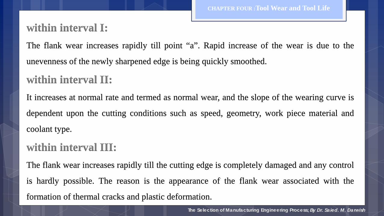
within interval I: The flank wear increases rapidly till point “a”. Rapid increase of the wear is due to the
unevenness of the newly sharpened edge is being quickly smoothed.
within interval II: It increases at normal rate and termed as normal wear, and the slope of the wearing curve is
dependent upon the cutting conditions such as speed, geometry, work piece material and
coolant type.
within interval III: The flank wear increases rapidly till the cutting edge is completely damaged and any control
is hardly possible. The reason is the appearance of the flank wear associated with the
formation of thermal cracks and plastic deformation.
CHAPTER FOUR :Tool Wear and Tool Life
The Selection of Manufacturing Engineering Process; By Dr. Saied. M. Darwish
4.2 Tool life (cutting edge durability)
The tool life can be expressed in different ways:
1. Actual cutting time to failure.
2. Length of work cut to failure.
3. Volume of material removed to failure.
4. Number of components produced to failure.
5. Cutting speed for a given time of failure.
CHAPTER FOUR :Tool Wear and Tool Life
The Selection of Manufacturing Engineering Process; By Dr. Saied. M. Darwish
Factors affecting tool life:
1. Material of machined workpiece.
2. Required surface quality of the workpiece.
3. Tool material.
4. Tool geometry and sharpening condition.
5. Fixation of tool and workpiece.
6. Machining variables such as, speed, feed, and depth of cut.
7. Type of coolant used.
8. Condition of cutting tool with respect to vibrations.
CHAPTER FOUR :Tool Wear and Tool Life
The Selection of Manufacturing Engineering Process; By Dr. Saied. M. Darwish
CHAPTER FOUR :Tool Wear and Tool Life
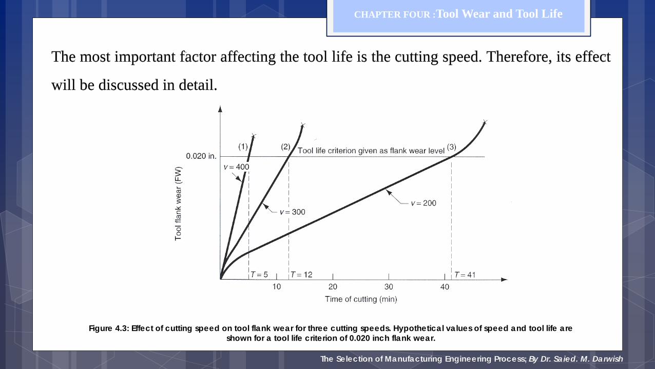
The most important factor affecting the tool life is the cutting speed. Therefore, its effect
will be discussed in detail.
Figure 4.3: Effect of cutting speed on tool flank wear for three cutting speeds. Hypothetical values of speed and tool life are shown for a tool life criterion of 0.020 inch flank wear.
The Selection of Manufacturing Engineering Process; By Dr. Saied. M. Darwish
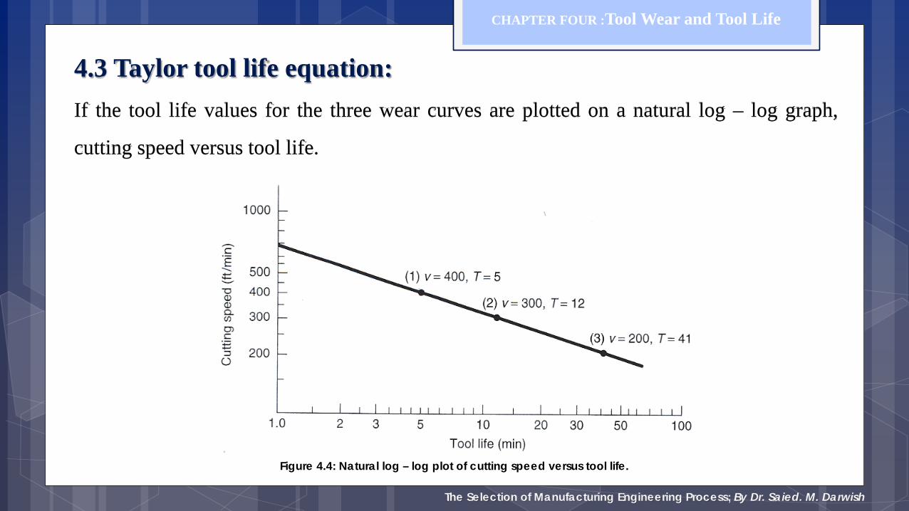
4.3 Taylor tool life equation: If the tool life values for the three wear curves are plotted on a natural log – log graph,
cutting speed versus tool life.
CHAPTER FOUR :Tool Wear and Tool Life
Figure 4.4: Natural log – log plot of cutting speed versus tool life.

The Selection of Manufacturing Engineering Process; By Dr. Saied. M. Darwish
The discovery of this relation around 1900 is credited to F.W. Taylor. It can be expressed in
equation form and it is called Taylor tool life equation.
CHAPTER FOUR :Tool Wear and Tool Life
CVT n =
n
TT
VV
=
2
1
1
2
nn TVTV 2211 =
21
12
loglogloglog
TTVVn
−−
=
where:
V = cutting speed (m/min)
T = Tool life (min)
C = a constant representing the cutting speed that results in 1 min tool life
n can be found as following:
The Selection of Manufacturing Engineering Process; By Dr. Saied. M. Darwish
4.4 Tool life criterion in production:
The criterion of Taylor equation is not practical in a factory environment, the
following are some alternates that are more convenient to use in production:
1. Changes in the sound emitting from operation.
2. Degradation of the surface finish on work.
3. Complete failure of cutting edge.
4. Workpiece count.
5. Chips become ribbon form or string
CHAPTER FOUR :Tool Wear and Tool Life
The Selection of Manufacturing Engineering Process; By Dr. Saied. M. Darwish
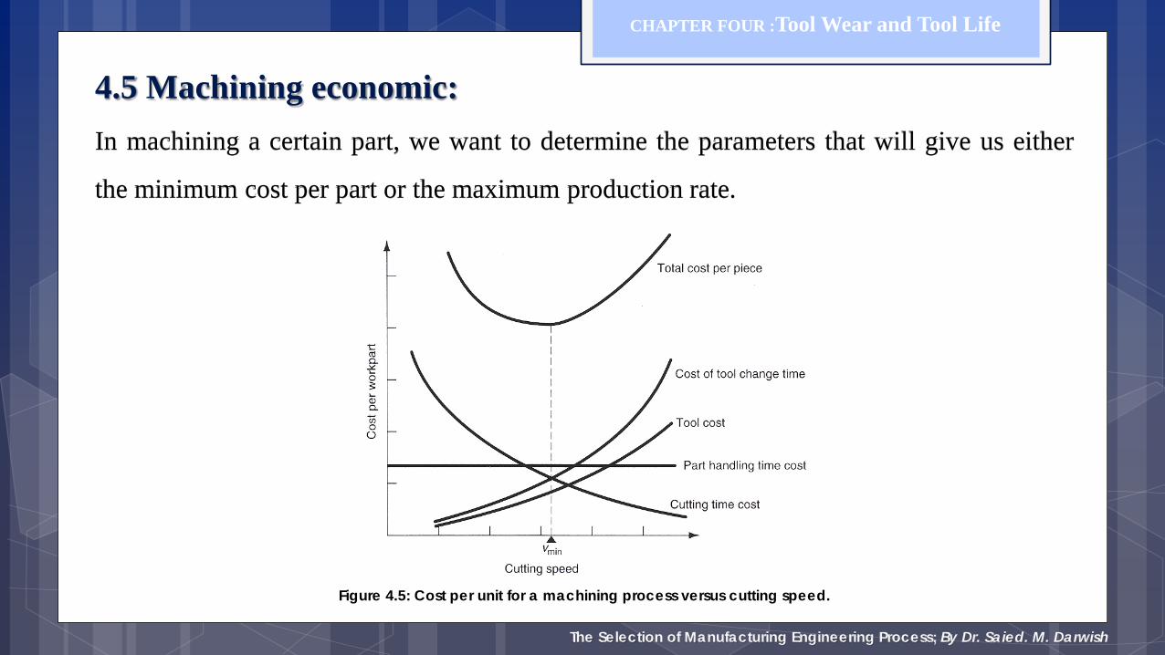
4.5 Machining economic: In machining a certain part, we want to determine the parameters that will give us either
the minimum cost per part or the maximum production rate.
CHAPTER FOUR :Tool Wear and Tool Life
Figure 4.5: Cost per unit for a machining process versus cutting speed.
The Selection of Manufacturing Engineering Process; By Dr. Saied. M. Darwish
CHAPTER FOUR :Tool Wear and Tool Life
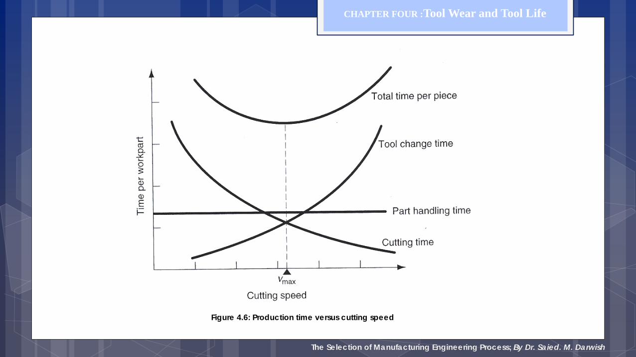
Figure 4.6: Production time versus cutting speed

The Selection of Manufacturing Engineering Process; By Dr. Saied. M. Darwish
The time needed to produce a part is:
CHAPTER FOUR :Tool Wear and Tool Life
Where:
Tl = time involved in loading and unloading the part, changing speed and feed rates.
Tm = machining time per part.
Tc = time required to grind the tool.
Np = number of parts machined per tool ground.
p
cmlp N
TTTT ++=
fVLD
fNLTm
π==

The Selection of Manufacturing Engineering Process; By Dr. Saied. M. Darwish
From tool life equation, we have:
CHAPTER FOUR :Tool Wear and Tool Life
Where T, is time, in minutes, required to reach a flank wear of certain dimension, after which the tool has
to be reground or changed. The number of pieces per tool grind is thus can be obtained as following:
mp T
TN =
1)/1(
/1
−= n
n
p LDVfCN
π
n
VCT
1
=
CVT n =
or

The Selection of Manufacturing Engineering Process; By Dr. Saied. M. Darwish
In order to find the optimum cutting speed and also the optimum tool life for maximum
production, we have to differentiate Tp with respect to V and set it to zero.
CHAPTER FOUR :Tool Wear and Tool Life
VTp
∂
∂
( )[ ]{ }nc
opt TnCV
1/1 −=
( )[ ] copt TnT 1/1 −=
we find that the optimum cutting speed Vopt now becomes,
and the optimum tool life is,
The Selection of Manufacturing Engineering Process; By Dr. Saied. M. Darwish
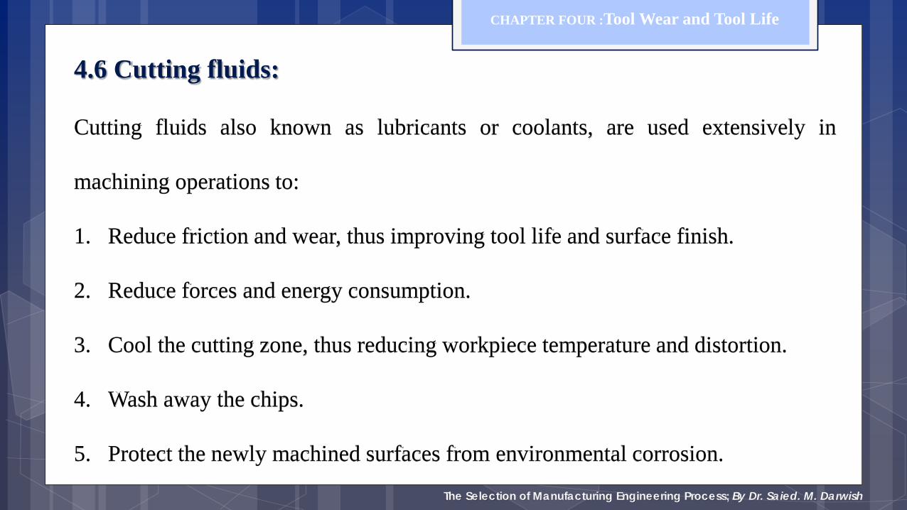
4.6 Cutting fluids:
Cutting fluids also known as lubricants or coolants, are used extensively in
machining operations to:
1. Reduce friction and wear, thus improving tool life and surface finish.
2. Reduce forces and energy consumption.
3. Cool the cutting zone, thus reducing workpiece temperature and distortion.
4. Wash away the chips.
5. Protect the newly machined surfaces from environmental corrosion.
CHAPTER FOUR :Tool Wear and Tool Life
The Selection of Manufacturing Engineering Process; By Dr. Saied. M. Darwish
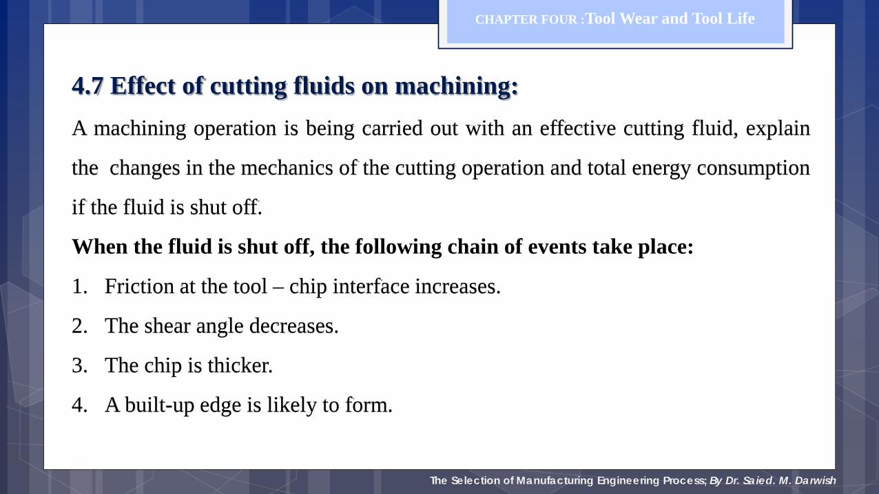
4.7 Effect of cutting fluids on machining: A machining operation is being carried out with an effective cutting fluid, explain
the changes in the mechanics of the cutting operation and total energy consumption
if the fluid is shut off.
When the fluid is shut off, the following chain of events take place:
1. Friction at the tool – chip interface increases.
2. The shear angle decreases.
3. The chip is thicker.
4. A built-up edge is likely to form.
CHAPTER FOUR :Tool Wear and Tool Life

The Selection of Manufacturing Engineering Process; By Dr. Saied. M. Darwish
As a consequence:
A. The shear energy in the primary zone increases.
B. The friction energy in the secondary zone increases.
C. The total energy increases.
D. Surface finish is likely to deteriorate.
E. The temperature in the cutting zone increases, hence the tool wear increases.
F. Tolerances may be difficult to maintain because of the increased temperature
and expansion of the workpiece during machining.
CHAPTER FOUR :Tool Wear and Tool Life

The Selection of Manufacturing Engineering Process; By Dr. Saied. M. Darwish
4.8 Selection of cutting fluid:
The selection of a cutting fluid should include the following consideration.
A. Effect on workpiece material. (Washing machined parts to remove any cutting
fluid residual).
B. Effect on machine tool (Compatibility with the machine member materials).
C. Biological effects (human and environment).
CHAPTER FOUR :Tool Wear and Tool Life
The Selection of Manufacturing Engineering Process; By Dr. Saied. M. Darwish
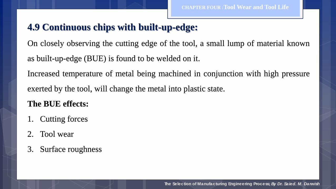
4.9 Continuous chips with built-up-edge: On closely observing the cutting edge of the tool, a small lump of material known
as built-up-edge (BUE) is found to be welded on it.
Increased temperature of metal being machined in conjunction with high pressure
exerted by the tool, will change the metal into plastic state.
The BUE effects:
1. Cutting forces
2. Tool wear
3. Surface roughness
CHAPTER FOUR :Tool Wear and Tool Life

The Selection of Manufacturing Engineering Process; By Dr. Saied. M. Darwish
4.9 Continuous chips with built-up-edge: BUE is formed periodically on the tools, when it reaches a comparatively large size, it breaks off and carried away by both, the chip and workpiece. It affects dimensional accuracy and surface finish. The tool rake angle and the cutting speed V, have a combined influence on the formation of the BUE. The machining condition should be selected to avoid the formation of BUE.
CHAPTER FOUR :Tool Wear and Tool Life