Embed Size (px)
Citation preview
Topic 8 The Series Circuit
T8 Series circuits encompassing:
circuit diagram of a single-source d.c. ‘series’ circuit.
Identification of the major components of a ‘series’ circuit: power supply; loads; connecting leads and switch
applications where ‘series’ circuits are used in the Electro technology industry.
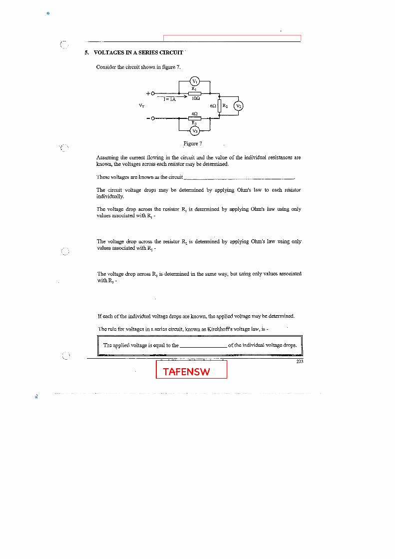
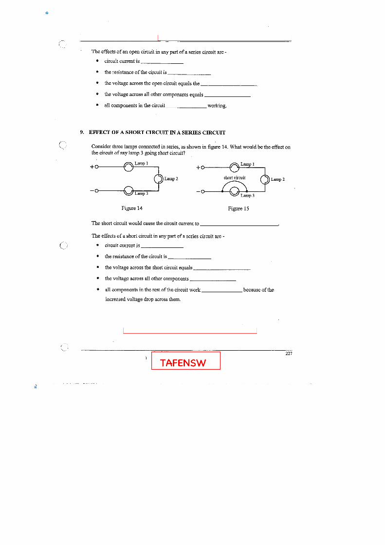
characteristics of a ‘series’ circuit - connection of loads, current path, voltage drops, power dissipation and effects of an open circuit in a ‘series’ circuit.
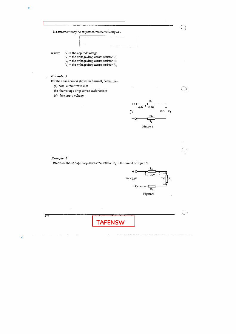
the voltage, current, resistances or power dissipated from measured or given values of any two of these quantities
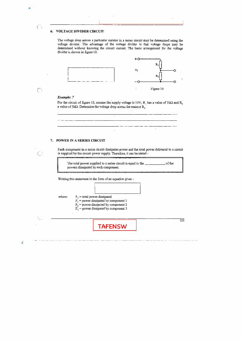
relationship between voltage drops and resistance in a simple voltage divider network.
setting up and connecting a single-source series dc circuit
measurement of resistance, voltage and current values in a single source series circuit
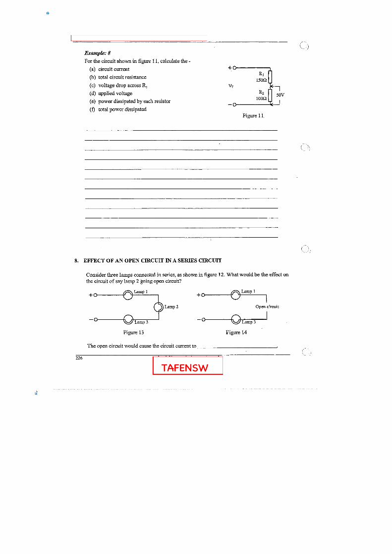
effect of an open-circuit on a series connected circuit
Lesson Plan Week 3 DC , July 2014Greg Moore
Week 3 Quiz, marked in class and hand back after scanning
TOPIC 8 Series Circuits, KVL (3 hour)
• main ppt and worksheets
• refer to Phillips text pages and see what's there
• my ppt KVL analysis
• Questions to do in class and remainder for homework
• Circuit maker 2000 lab re KVL
TOPIC 4 Introduce Power **** originally not planned (2 hour)
• worksheets and ppt
• Phillips text notes refer to
• Tutorial questions about power
TOPIC 6 EMF sources (1.5 hour)
• main ppt and worksheets
• Lab in class with Vinegar and Salt
• Demo in class about the effects of salt as to conduction in a fluid.
• Tutorial questions about EMF sources.
Additionally, think do breadboard, Fritzing with resistors and wires.
Introduce resistor colour codes, basic identification and measurement.
This is provided have time.
We will do more on power dissipation a little later…. just introduce power here first time in week 2 and 3 of the nine week program.
In class Circuit maker 200 lab for this this topic.
The lab from week 2, with graphs of Vdrop across resistors and current flowing in the circuit more than covers what is here in section 8.
Demonstration of cell voltages reversed (opposing maybe handy here)
23
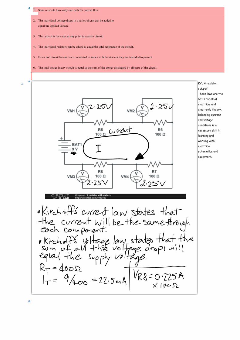
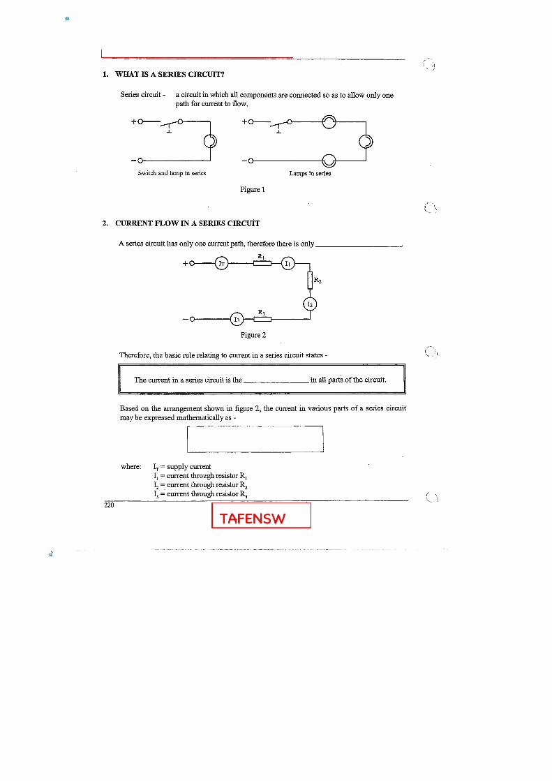
1. Series circuits have only one path for current flow.
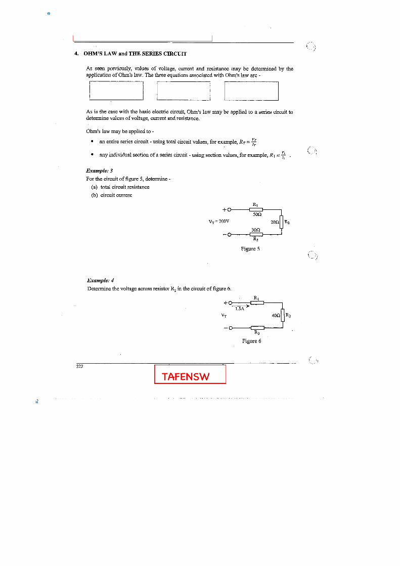
2. The individual voltage drops in a series circuit can be added to
equal the applied voltage.
3. The current is the same at any point in a series circuit.
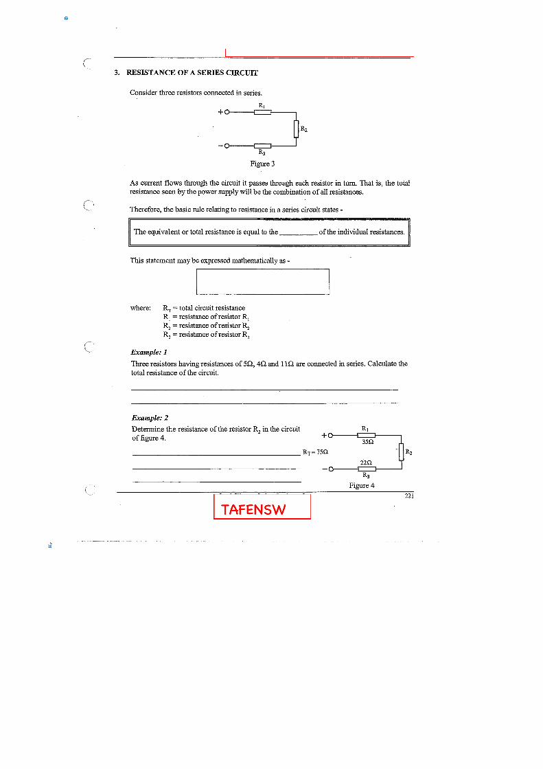
4. The individual resistors can be added to equal the total resistance of the circuit.
5. Fuses and circuit breakers are connected in series with the devices they are intended to protect.
6. The total power in any circuit is equal to the sum of the power dissipated by all parts of the circuit.
KVL 4 resistor
cct.pdf
These laws are the
basis for all of
electrical and
electronic theory.
Balancing current
and voltage
conditions is a
necessary skill in
learning and
working with
electrical
schematics and
equipment.
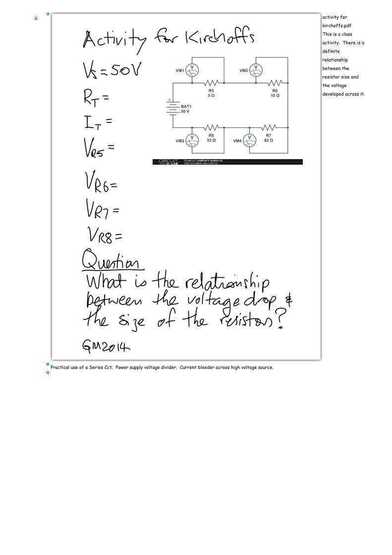
activity for
kirchoffs.pdf
This is a class
activity. There is a
definite
relationship
between the
resistor size and
the voltage
developed across it.
Practical use of a Series Cct. Power supply voltage divider. Current bleeder across high voltage source.
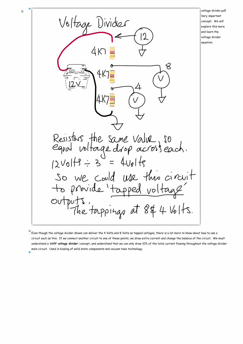
voltage divider.pdf
Very important
concept. We will
explore this more
and learn the
voltage divider
equation.
Even though the voltage divider shown can deliver the 4 Volts and 8 Volts as tapped voltages, there is a lot more to know about how to use a
circuit such as this. If we connect another circuit to one of these points, we draw extra current and change the balance of the circuit. We must
understand a ‘stiff voltage divider’ concept, and understand that we can only draw 10% of the total current flowing throughout the voltage divider
main circuit. Used in biasing of solid state components and vacuum tube technology.