Embed Size (px)
Citation preview
Topper Mower, Parks Mower
OWNERS/OPERATORS MANUAL
AND SPARE PARTS LIST
Models: TM, PM, OM, PMM Mini

2
Introduction
Your FIELDMASTER mower has been designed to do a range of work to your satisfaction. This list of instructions covers the basic requirement for maintenance and will ensure good service if carried out.
Please read the whole of this manual and familiarise yourself and/or any other operators that may be required to operate this machine before attempting to
(a) fit the machine to the tractor,(b) carry out any adjustments,(c) operate the machine.
General Safety Precautions
*¶ Preventing accidents is the responsibility of every equipment operator.- DO NOT allow persons to operate machine without proper INSTRUCTIONS in the use of the machine.- (DO NOT USE FOR PURPOSES OTHER THAN FOR WHICH THE MACHINE IS DESIGNED).- In adjustments and operating factors recommended for particular uses.- In maintenance of safety guards and all factors of machine servicing for safe operation.- A safe speed to operate machine taking to account particular site and use.
STOP MACHINE
- BEFORE DISMOUNTING FROM TRACTOR- MAKING ANY ADJUSTMENT TO MACHINE- CLEARING ANY BLOCKAGE OR OBSTACLE
Keep children and spectators clear – ejected material can fly some distance.Inspect machine regularly for damaged blades or wear – replace any damage before continued use.
Lubrication is cheap maintenance – adhere to recommended servicing schedule.
IMPORTANT
Check and tighten all bolts on your machine after the first few hours of operation.
Fitting to the Tractor
Ensure tractor linkage is level – adjust. Drop arm wind handle to enable machine to lift evenly and sit evenly on ground. Top link bracket should be in floating position after selecting preferred cutting height (on roller or wheels). Precise cutting height can be varied using roller or wheel adjustments.Check driveshaft length to ensure shaft does not “bottom” when machine is raised, (shafts can be shortened by cutting male and female tube). At any position, the telescoping tubes must be at least 1/3 engaged.Set stop on hydraulic quadrant to prevent over lifting machine and damaging driveshaft on machine front edge when in raised position or excessive PTO angle.Adjust linkage sway chains to prevent unnecessary machine side movement.Before the initial start up of the machine, check gearbox oil level, belt adjustment is correct and all bolts are tight.
The Telescopic Drive Shaft
After hitching up, the telescopic drive shaft can be attached. Careful attention should be given because only correct fitting of this unit can give the best service.
Check the driveshaft length to ensure shaft does not “bottom out” when machine is raised or lowered.
There is a wide range of tractors and the horizontal distance between the power take off shaft and the drawbar varies considerably. A specific instruction for each would require extensive research. However, taking for example the minimum and maximum conditions, safe working lengths of the drive shaft are given as follows:
At any position, the driveshaft tubes must be engaged together by at least 1/3 of the length of the telescoping tubes.
Should your driveshaft need shortening, simply remove the plastic safety covers and cut the steel tubing to the required length with a saw, remove any rough edges or burrs, then refit the safety covers.
Ensure that both splined yokes are securely fastened to the splined shaft on both the tractor and the mower.
WARNINGWARNING
Page 1
Introduction
Your FIELDMASTER mower has been designed to do a range of work to your satisfaction. This list of instructions covers the basic requirement for maintenance and will ensure good service if carried out.
Please read the whole of this manual and familiarise yourself and/or any other operators that may be required to operate this machine before attempting to
(a) fit the machine to the tractor,(b) carry out any adjustments,(c) operate the machine.
General Safety Precautions
*¶ Preventing accidents is the responsibility of every equipment operator.- DO NOT allow persons to operate machine without proper INSTRUCTIONS in the use of the machine. - (DO NOT USE FOR PURPOSES OTHER THAN FOR WHICH THE MACHINE IS DESIGNED).- In adjustments and operating factors recommended for particular uses.- In maintenance of safety guards and all factors of machine servicing for safe operation.- A safe speed to operate machine taking to account particular site and use.
STOP MACHINE
- BEFORE DISMOUNTING FROM TRACTOR- MAKING ANY ADJUSTMENT TO MACHINE- CLEARING ANY BLOCKAGE OR OBSTACLE
Keep children and spectators clear – ejected material can fly some distance.Inspect machine regularly for damaged blades or wear – replace any damage before continued use.
Lubrication is cheap maintenance – adhere to recommended servicing schedule.
IMPORTANT
Check and tighten all bolts on your machine after the first few hours of operation.
Fitting to the Tractor
Ensure tractor linkage is level – adjust. Drop arm wind handle to enable machine to lift evenly and sit evenly on ground. Top link bracket should be in floating position after selecting preferred cutting height (on roller or wheels). Precise cutting height can be varied using roller or wheel adjustments.Check driveshaft length to ensure shaft does not “bottom” when machine is raised, (shafts can be shortened by cutting male and female tube). At any position, the telescoping tubes must be at least 1/3 engaged.Set stop on hydraulic quadrant to prevent over lifting machine and damaging driveshaft on machine front edge when in raised position or excessive PTO angle.Adjust linkage sway chains to prevent unnecessary machine side movement.Before the initial start up of the machine, check gearbox oil level, belt adjustment is correct and all bolts are tight.
The Telescopic Drive Shaft
After hitching up, the telescopic drive shaft can be attached. Careful attention should be given because only correct fitting of this unit can give the best service.
Check the driveshaft length to ensure shaft does not “bottom out” when machine is raised or lowered.
There is a wide range of tractors and the horizontal distance between the power take off shaft and the drawbar varies considerably. A specific instruction for each would require extensive research. However, taking for example the minimum and maximum conditions, safe working lengths of the drive shaft are given as follows:
At any position, the driveshaft tubes must be engaged together by at least 1/3 of the length of the telescoping tubes.
Should your driveshaft need shortening, simply remove the plastic safety covers and cut the steel tubing to the required length with a saw, remove any rough edges or burrs, then refit the safety covers.
Ensure that both splined yokes are securely fastened to the splined shaft on both the tractor and the mower.
WARNINGWARNING
Page 1
3
Page 2
Operation Hints
1. Set cutting height high for initial cut in any area where obstacles are unknown.2. Machines operate best at 540 PTO delivery.
(a) Let rotor speed reach this speed before commencing tractor forward.(b) Achieve suitable ground speed with tractor gears rather than using throttle continuously.
3. Anti-scalp saucers can be fitted to centre or all spindles – recommended in undulating conditions – will increase blade and belt life in addition to preventing scalping.
4. Roller models are generally recommended for safety reasons (roller performs completed discharge barrier) and also enables mowing over kerbs or garden edges saving manual trimming.
5. During operation of the machine, the weight of the mower should be carried on the rear roller and lower link arms of the tractor. The top link toggle should be able to float at all times to allow the mower to follow the contour of the ground.
6. Only use the top link toggle in 'fixed' or 'rigid' position during transport of the mower. Failure to fix the top link toggle in rigid position during transport will result in severe deck, frame or chassis cracking.
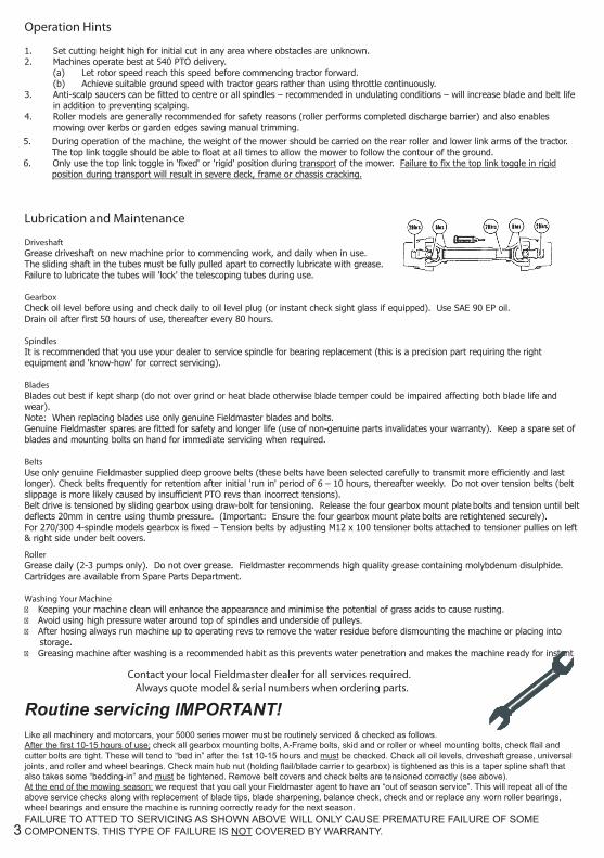
Lubrication and Maintenance
DriveshaftGrease driveshaft on new machine prior to commencing work, and daily when in use.The sliding shaft in the tubes must be fully pulled apart to correctly lubricate with grease. Failure to lubricate the tubes will 'lock' the telescoping tubes during use.
GearboxCheck oil level before using and check daily to oil level plug (or instant check sight glass if equipped). Use SAE 90 EP oil.Drain oil after first 50 hours of use, thereafter every 80 hours.
SpindlesIt is recommended that you use your dealer to service spindle for bearing replacement (this is a precision part requiring the right equipment and 'know-how' for correct servicing).
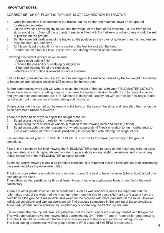
BladesBlades cut best if kept sharp (do not over grind or heat blade otherwise blade temper could be impaired affecting both blade life and wear).Note: When replacing blades use only genuine Fieldmaster blades and bolts.Genuine Fieldmaster spares are fitted for safety and longer life (use of non-genuine parts invalidates your warranty). Keep a spare set of blades and mounting bolts on hand for immediate servicing when required.
BeltsUse only genuine Fieldmaster supplied deep groove belts (these belts have been selected carefully to transmit more efficiently and last longer). Check belts frequently for retention after initial 'run in' period of 6 – 10 hours, thereafter weekly. Do not over tension belts (belt slippage is more likely caused by insufficient PTO revs than incorrect tensions).Belt drive is tensioned by sliding gearbox using draw-bolt for tensioning. Release the four gearbox mount plate bolts and tension until belt deflects 20mm in centre using thumb pressure. (Important: Ensure the four gearbox mount plate bolts are retightened securely).For 270/300 4-spindle models gearbox is fixed – Tension belts by adjusting M12 x 100 tensioner bolts attached to tensioner pullies on left & right side under belt covers.
RollerGrease daily (2-3 pumps only). Do not over grease. Fieldmaster recommends high quality grease containing molybdenum disulphide. Cartridges are available from Spare Parts Department.
Washing Your MachineKeeping your machine clean will enhance the appearance and minimise the potential of grass acids to cause rusting.Avoid using high pressure water around top of spindles and underside of pulleys.After hosing always run machine up to operating revs to remove the water residue before dismounting the machine or placing into storage.Greasing machine after washing is a recommended habit as this prevents water penetration and makes the machine ready for instant use.
Contact your local Fieldmaster dealer for all services required.Always quote model & serial numbers when ordering parts.
Page 2
Operation Hints
1. Set cutting height high for initial cut in any area where obstacles are unknown.2. Machines operate best at 540 PTO delivery.
(a) Let rotor speed reach this speed before commencing tractor forward.(b) Achieve suitable ground speed with tractor gears rather than using throttle continuously.
3. Anti-scalp saucers can be fitted to centre or all spindles – recommended in undulating conditions – will increase blade and belt lifein addition to preventing scalping.
4. Roller models are generally recommended for safety reasons (roller performs completed discharge barrier) and also enables mowing over kerbs or garden edges saving manual trimming.
5. Optional front castor wheel assemblies can be fitted to enable all contour mowing – Golf course – embankments, etc. Note Top link bracket should be mounted in pivoting position when front wheel assemblies fitted.
6. During operation of the machine, the weight of the mower should be carried on the rear roller and lower link arms of the tractor. The top link toggle should be able to float at all times to allow the mower to follow the contour of the ground.
7. Only use the top link toggle in 'fixed' or 'rigid' position during transport of the mower. Failure to fix the top link toggle in rigid position during transport will result in severe deck, frame or chassis cracking.
Lubrication and Maintenance
DriveshaftGrease driveshaft on new machine prior to commencing work, and daily when in use.The sliding shaft in the tubes must be fully pulled apart to correctly lubricate with grease. Failure to lubricate the tubes will 'lock' the telescoping tubes during use.
GearboxCheck oil level before using and check daily to oil level plug (or instant check sight glass if equipped). Use SAE 90 EP oil.Drain oil after first 50 hours of use, thereafter every 80 hours.
SpindlesIt is recommended that you use your dealer to service spindle for bearing replacement (this is a precision part requiring the rightequipment and 'know-how' for correct servicing).
BladesBlades cut best if kept sharp (do not over grind or heat blade otherwise blade temper could be impaired affecting both blade life and wear).Note: When replacing blades use only genuine Fieldmaster blades and bolts.Genuine Fieldmaster spares are fitted for safety and longer life (use of non-genuine parts invalidates your warranty). Keep a spare set of blades and mounting bolts on hand for immediate servicing when required.
BeltsUse only genuine Fieldmaster supplied deep groove belts (these belts have been selected carefully to transmit more efficiently and lastlonger). Check belts frequently for retention after initial 'run in' period of 6 – 10 hours, thereafter weekly. Do not over tension belts (belt slippage is more likely caused by insufficient PTO revs than incorrect tensions).Belt drive is tensioned by sliding gearbox using draw-bolt for tensioning. Release the four gearbox mount plate bolts and tension until beltdeflects 20mm in centre using thumb pressure. (Important: Ensure the four gearbox mount plate bolts are retightened securely).For 270/300 4-spindle models gearbox is fixed – Tension belts by adjusting M12 x 100 tensioner bolts attached to tensioner pullies on left& right side under belt covers.
RollerGrease daily (2-3 pumps only). Do not over grease. Fieldmaster recommends high quality grease containing molybdenum disulphide. Cartridges are available from Spare Parts Department.
Washing Your MachineKeeping your machine clean will enhance the appearance and minimise the potential of grass acids to cause rusting.Avoid using high pressure water around top of spindles and underside of pulleys.After hosing always run machine up to operating revs to remove the water residue before dismounting the machine or placing into storage.Greasing machine after washing is a recommended habit as this prevents water penetration and makes the machine ready for instant use.
Contact your local Fieldmaster dealer for all services required.Always quote model & serial numbers when ordering parts.
Routine servicing IMPORTANT!Like all machinery and motorcars, your 5000 series mower must be routinely serviced & checked as follows.After the first 10-15 hours of use; check all gearbox mounting bolts, A-Frame bolts, skid and or roller or wheel mounting bolts, check flail and cutter bolts are tight. These will tend to “bed in” after the 1st 10-15 hours and must be checked. Check all oil levels, driveshaft grease, universal joints, and roller and wheel bearings. Check main hub nut (holding flail/blade carrier to gearbox) is tightened as this is a taper spline shaft that also takes some “bedding-in” and must be tightened. Remove belt covers and check belts are tensioned correctly (see above).At the end of the mowing season; we request that you call your Fieldmaster agent to have an “out of season service”. This will repeat all of the above service checks along with replacement of blade tips, blade sharpening, balance check, check and or replace any worn roller bearings, wheel bearings and ensure the machine is running correctly ready for the next season.FAILURE TO ATTED TO SERVICING AS SHOWN ABOVE WILL ONLY CAUSE PREMATURE FAILURE OF SOME COMPONENTS. THIS TYPE OF FAILURE IS NOT COVERED BY WARRANTY.
Introduction
Your FIELDMASTER mower has been designed to do a range of work to your satisfaction. This list of instructions covers the basic requirement for maintenance and will ensure good service if carried out.
Please read the whole of this manual and familiarise yourself and/or any other operators that may be required to operate this machine before attempting to
(a) fit the machine to the tractor,(b) carry out any adjustments,(c) operate the machine.
General Safety Precautions
*¶ Preventing accidents is the responsibility of every equipment operator.- DO NOT allow persons to operate machine without proper INSTRUCTIONS in the use of the machine. - (DO NOT USE FOR PURPOSES OTHER THAN FOR WHICH THE MACHINE IS DESIGNED).- In adjustments and operating factors recommended for particular uses.- In maintenance of safety guards and all factors of machine servicing for safe operation.- A safe speed to operate machine taking to account particular site and use.
STOP MACHINE
- BEFORE DISMOUNTING FROM TRACTOR- MAKING ANY ADJUSTMENT TO MACHINE- CLEARING ANY BLOCKAGE OR OBSTACLE
Keep children and spectators clear – ejected material can fly some distance.Inspect machine regularly for damaged blades or wear – replace any damage before continued use.
Lubrication is cheap maintenance – adhere to recommended servicing schedule.
IMPORTANT
Check and tighten all bolts on your machine after the first few hours of operation.
Fitting to the Tractor
Ensure tractor linkage is level – adjust. Drop arm wind handle to enable machine to lift evenly and sit evenly on ground. Top link bracket should be in floating position after selecting preferred cutting height (on roller or wheels). Precise cutting height can be varied using roller or wheel adjustments.Check driveshaft length to ensure shaft does not “bottom” when machine is raised, (shafts can be shortened by cutting male and female tube). At any position, the telescoping tubes must be at least 1/3 engaged.Set stop on hydraulic quadrant to prevent over lifting machine and damaging driveshaft on machine front edge when in raised position or excessive PTO angle.Adjust linkage sway chains to prevent unnecessary machine side movement.Before the initial start up of the machine, check gearbox oil level, belt adjustment is correct and all bolts are tight.
The Telescopic Drive Shaft
After hitching up, the telescopic drive shaft can be attached. Careful attention should be given because only correct fitting of this unit can give the best service.
Check the driveshaft length to ensure shaft does not “bottom out” when machine is raised or lowered.
There is a wide range of tractors and the horizontal distance between the power take off shaft and the drawbar varies considerably. A specific instruction for each would require extensive research. However, taking for example the minimum and maximum conditions, safe working lengths of the drive shaft are given as follows:
At any position, the driveshaft tubes must be engaged together by at least 1/3 of the length of the telescoping tubes.
Should your driveshaft need shortening, simply remove the plastic safety covers and cut the steel tubing to the required length with a saw, remove any rough edges or burrs, then refit the safety covers.
Ensure that both splined yokes are securely fastened to the splined shaft on both the tractor and the mower.
WARNINGWARNING
Page 1
4
IMPORTANT NOTES:
CORRECT SET-UP OF ‘FLOATING TOP LINK’ SLOT / CONNECTION TO TRACTOR:
1. Once the machine is connected to the tractor, set the tractor and machine down on flat ground(preferably concrete)
2. Lift the lower link arms slightly to just take the weight of the front of the machine (i.e. the front of theskids would be 5mm off the ground). If machine fitted with front wheels or rollers these should be setto just run on the ground.
3. Set the lower link draft arms of the tractor at this position so they cannot go lower than this, and ensurethey can float. (I.e. not fixed)
4. At this point, set the top link into the centre of the top link slot (not the hole)5. Ensure the fixed top link hole is only ever used during transport of the machine.
Following this correct procedure will ensure:-A good even cutting finish-Reduce the possibility of scalping or digging in-Extended wearing life of the side skids-Machine construction is relieved of undue stresses
Failure to set up as above can result in serious damage to the machine caused by tractor weight transferring to headstock and chassis which is NOT covered by the warranty.
Before commencing work you will want to adjust the height of the cut. With your FIELDMASTER MOWER Series here are numerous cutting heights to achieve the optimum desired length of cut to prevent scalping and give an even and accurate cut. N.B. Machine is designed / factory set with correct ‘lean-in’ angle (blade tip lower at front than rear)for efficient cutting and discharge.
Simple adjustment is carried out by removing the bolts on the side of the skids and relocating them once the skids have been raised or lowered.
There are three basic ways to adjust the height of the cut: 1. By adjusting the skids in relation to mowing deck;2. By adjusting the rear roller or wheels in relation to the mowing deck and skids; (if fitted)3. By adjusting both the roller assembly or wheels separately (if fitted) in relation to the mowing deck to
give a wide range of roller-to-skids positioning in conjunction with altering the height of cut.
It is important to set your FIELDMASTER MOWER up correctly for mowing according to the ground conditions.
Firstly, in the optimum flat field mowing the Fl ELDMASTER should be used on the roller only with the skids approximately one inch higher above the roller to give stability on any slight unevenness and to avoid any undue lateral roll of the FIELDMASTER at higher speeds.
Secondly, where mowing is not in so perfect a condition, it is important that the skids are set at approximately the same height as the roller when fitted.
Thirdly, in more extreme undulations and rougher ground it is best to have the roller (where fitted) about one inch above the skids.These three setting positions for three different types of mowing applications have proved to be the most satisfactory.
There are other points which could be mentioned, such as wet conditions where it's important that the roller takes most of the weight of the machine rather than the skid to avoid skid marks and also in very dry conditions if the ground is reasonable skid wear can be reduced with more pressure on the roller. However, individual conditions and varying operators will find success sometimes in the varying of these conditions.A finer adjustment can be achieved by lengthening or shortening the tractor top link arm.
It is important that the top link arm is adjusted so that the skid runners are running parallel with the ground. This will automatically give the mowing deck approximately 3/4" (19mm) 'lead-in' required for good mowing. This check should be made with tractor and mower on level surfaces with mower in cutting position.The best cutting performance will be gained when a RPM speed of 540 RPM is maintained.


WARRANTY
The manufacturer's obligation under this warranty is limited to correcting without charge at its factory or by one of its authorised Dealers, with the manufacturer's approval, any parts thereof, within 12 months from date of purchase by the original user, and which upon examination shall disclose to the manufacturer's satisfaction to have been originally defective.
Correction of such defect by repair to, or supplying of replacements of defective parts, shall constitute fulfillment of all obligations to the original user: Manufacturer shall not be liable for loss, damage, or expense directly or indirectly from the use of its product or from any other cause. Defective parts must be returned freight paid each way by the purchaser to the manufacturer.
This warranty shall not apply to any parts which must be replaced because of normal wear, or which have been subject to misuse, negligence or accident or which have been repaired or altered outside of the manufacturer's factory, unless authorised by the manufacture. This warranty should not be construed as a free service period during the warranty period.
68 Adams Drive Pukekohe
Ph: 0800 500 275