Embed Size (px)
Citation preview

© 2017 IOP Publishing Ltd
1. Introduction
Biomimetic compound eyes have attracted much attention in recent years, thanks to their advantages of a wide field of view (FOV) and high acuity to the motion of objects [1, 2]. While a human’s eyes adjust muscles to move the eyeballs, the compound eyes of insects utilize multiple lenses to receive information simultaneously. Several researchers have investigated the vergence movements in the compound eyes of the fly [3, 4]. These features have inspired researchers to develop sophisticated imaging systems for various applications such as display technologies and security surveillance cameras [5–7]. Recently, a bio-inspired photosensitivity enhancer has been developed for low-light imaging systems [8]. Nevertheless, most compound eyes are not tunable and are made of an array of fixed lenses on a hemispherical rigid support, with imaging sensors placed at the plane of focal points [9–11]. One drawback of fixed lenses is their limited viewing angle. The distance between the object and the lenses farther from the central axis increases beyond a certain angle, resulting in images being out of focus, a phenomenon known as gap mismatch. By integrating tunable lenses, the capability of a compound eye may be enhanced by acquiring focused images. Compound eyes that exploit tunable lenses could overcome the gap mismatch by adjusting the focal length of the lenses close to the edge. Very recently, tunable compound
eyes have been demonstrated using hydrogel actuators and near-infrared irradiation [12, 13]. However, these designs have a fixed curvature of the substrate of the lens and do not accommodate focal length changes, while individual lenses change their shapes.
Electrowetting on dielectric (EWOD) is the electrical actuation of a conducting droplet on top of an electrode covered with a hydrophobic insulating layer [14]. Due to its advantages of low cost, a fast response time and simple fabrication, EWOD has been used for the design of tunable liquid lenses, including planar electrodes on a rigid substrate, a glass chamber with two immiscible liquids, etc [15–19]. In the current design of liquid lenses, only R1 (the radius of the curvature of the lens) is tunable, while R2 (the second curvature of the lens) is fixed, typically at infinity [20]. One restriction of a transparent electrode such as the indium tin oxide (ITO) type is its lack of mechanical flexibility. Recently, our group has proposed a single liquid lens using graphene; a new, flexible, transparent and electrically conductive electrode [21–23]. Graphene electrodes allow deforma-tion of the flexible substrate by applying large pressure, which is useful for a compound eye application [24–26].
One of the fundamental limitations of optical lenses is spherical aberration, which degrades the image qual-ity. Spherical aberration is caused by the deviation of the lens geometry from an ideal sphere (a sphere with the center located at the focal point and radii of curva-ture equal to the focal length). Aberration results in the
A Shahini et al
046002
BBIICI
© 2017 IOP Publishing Ltd
12
Bioinspir. Biomim.
BB
1748-3190
10.1088/1748-3190/aa7084
4
1
9
Bioinspiration & Biomimetics
IOP
8
June
2017
Toward individually tunable compound eyes with transparent graphene electrode
Ali Shahini1, Hai Jin3, Zhixian Zhou2, Yang Zhao1, Pai-Yen Chen1, Jing Hua3 and Mark Ming-Cheng Cheng1
1 Department of Electrical and Computer Engineering, Wayne State University, Detroit, MI 48202, United States of America2 Department of Physics and Astronomy, Wayne State University, Detroit, MI 48201, United States of America3 Computer Science Department, Wayne State University, Detroit, MI 48202, United States of America
E-mail: [email protected] and [email protected]
Keywords: liquid lens, compound eyes, EWOD, graphene
AbstractWe present tunable compound eyes made of ionic liquid lenses, of which both curvatures (R1 and R2 in the lensmaker’s equation) can be individually changed using electrowetting on dielectric (EWOD) and applied pressure. Flexible graphene is used as a transparent electrode and is integrated on a flexible polydimethylsiloxane (PDMS)/parylene hybrid substrate. Graphene electrodes allow a large lens aperture diameter of between 2.4 mm and 2.74 mm. Spherical aberration analysis is performed using COMSOL to investigate the optical property of the lens under applied voltage and pressure. The final lens system shows a resolution of 645.1 line pair per millimeter. A prototype of a tunable lens array is proposed for the application of a compound eye.
PAPER2017
RECEIVED 5 February 2017
REVISED
26 April 2017
ACCEPTED FOR PUBLICATION
2 May 2017
PUBLISHED 8 June 2017
https://doi.org/10.1088/1748-3190/aa7084Bioinspir. Biomim. 12 (2017) 046002
2
A Shahini et al
parallel rays emanating from the exit pupil failing to converge on the same point. For the planar lens array (plano-convex lenses), the marginal rays (rays farther from the optical axis) converge at a closer point com-pared to the paraxial rays (rays closer to the optical axis). Spherical aberration can be even more severe in EWOD-based lenses, as the dynamic change of the liq-uid curvature under applied voltages results in greater deviation from the ideal sphere [16]. One strategy to minimize spherical aberration is to tune the second curvature of the lens (R2) to its best form, making it a meniscus lens [27]. This is the most commonly used type of lens in corrective lenses (wearable spectacles).
In this paper, we propose a tunable compound eye made of an array of liquid lenses integrated on a thin free-standing flexible polydimethylsiloxane (PDMS)/parylene membrane which allows recoverable defor-mation under applied pressure. The radii of both curva-tures, R1 (liquid lens) and R2 (supporting membrane), can be adjusted using EWOD actuation and pneumatic pressure, respectively. Spherical aberration is investi-gated by fine-tuning R2 under applied pressure. The lens system exploits well-established graphene elec-trodes with planar processing approaches for EWOD actuation, resulting in a resolution of 645.1 line pairs per millimeter (lp mm−1) with a large lens aperture
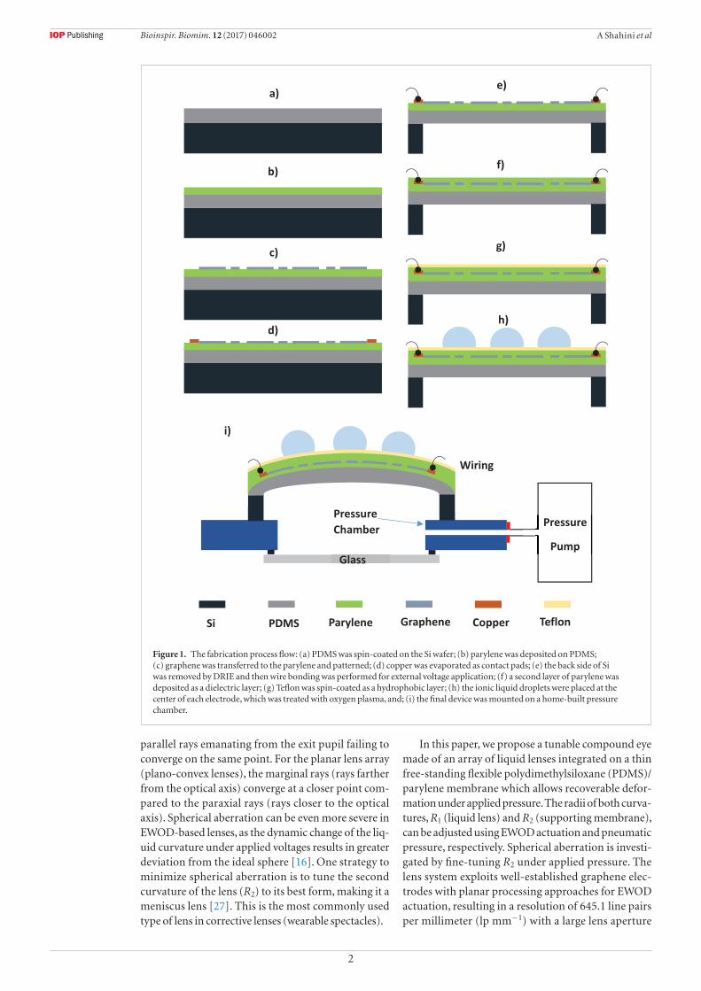
Figure 1. The fabrication process flow: (a) PDMS was spin-coated on the Si wafer; (b) parylene was deposited on PDMS; (c) graphene was transferred to the parylene and patterned; (d) copper was evaporated as contact pads; (e) the back side of Si was removed by DRIE and then wire bonding was performed for external voltage application; (f) a second layer of parylene was deposited as a dielectric layer; (g) Teflon was spin-coated as a hydrophobic layer; (h) the ionic liquid droplets were placed at the center of each electrode, which was treated with oxygen plasma, and; (i) the final device was mounted on a home-built pressure chamber.
Bioinspir. Biomim. 12 (2017) 046002

3
A Shahini et al
diameter between 2.4 mm and 2.74 mm. Our motiv-ation in this paper is to propose a system of lenses that constitutes a scalable pathway to a working artificial compound eye with tunable lenses and a large FOV.
2. Materials and methods
The details of the fabrication process of the device are shown in figure 1. PDMS of thickness 100 µm was first spin-coated on a Si wafer and cured at 80 °C for 4 h (figure 1(a)). A 4 µm parylene layer was then deposited by chemical vapor deposition (CVD) on top of the PDMS to form a transparent and flexible substrate of the lens (figure 1(b)). Single-layer graphene was synthesized using chemical vapor deposition with a copper substrate. Graphene sheets were transferred to the PDMS/parylene substrate. Graphene was patterned into concentric-shaped electrodes using photolithography and oxygen plasma (figure 1(c)). A Cu layer (150 nm) was deposited by electron-beam evaporation and patterned as contact pads (figure 1(d)). The back side of the Si wafer was removed using deep reactive ion etching (DRIE, Bosch process) with an aluminum mask, to create a free-standing membrane of PDMS (figure 1(e)). Wire bonding was performed using a kit of silver conductive epoxy (Micron Meters 36 AWG). A second layer of parylene (0.8 µm) was deposited as a dielectric layer using CVD (figure 1(f)). Teflon (1–3% DuPont AF 1600 diluted in 3 M FC72) was spin-coated as a hydrophobic layer (figure 1(g)). Imide ionic liquid, DEME-TFSI (N,N-diethyl-N-(2-methoxyethyl)- N-methyl-ammoniumbis (trifluoromethylsulfonyl), was used as lens liquid due to its low vapor pressure
and low surface tension (figure 1(h)) [28–31]. A short-time oxygen plasma was used to create a small hydrophilic region on the Teflon to facilitate placement of the droplets. Finally, the device was mounted on a home-built pressure chamber(figure 1(i)). A portable pressure source (Stratagene Pressure Control Station) was used to apply constant pressure to the membrane. This pressure source has a mechanism to control the amount of pressure from the pressure inlet. The test setup for voltage application was identical to that used in our previous paper [23].
The lensmaker’s equation correlates the focal length ( f ) to R1 and R2 [32]:
= − − +−⎡
⎣⎢⎤⎦⎥f
nR R
n D
nR R
11
1 1 1,
1 2 1 2
( ) ( ) (1)
where n and D are the refractive index and the height of a droplet, respectively. One of the key advantages of an insect’s compound eyes compared with the human eye is the larger FOV, owing to the spherical arrangement of the single lenses on a curved surface. Bio-inspired compound eye lenses could be beneficial in applications where a larger FOV is required, such as laparoscopic imaging. The ability to increase the FOV without moving the laparoscope head can prevent potential damage to the tissues during surgery. Figure 2 shows the simulation results of ray-tracing for a compound eye using COMSOL in which a larger FOV could be achieved without moving the image sensors. When pressure is applied to the membrane, it deforms the membrane into a spherical cap that allows the lenses to orient at varying angles, resulting in a wider FOV. For a single lens, we have shown that a 6 mm
Figure 2. COMSOL simulation of a ray-tracing diagram for compound eyes. (a) All the lenses have identical geometry. (b) Applying pressure to the membrane increases the curvature of the supporting membrane in order to achieve a larger FOV. This results in a gap mismatch between the lenses and the image sensors. (c) Changing the curvature of the lenses individually by EWOD resolves the gap mismatch.
Bioinspir. Biomim. 12 (2017) 046002
4
A Shahini et al
increase to the FOV could be achieved by a membrane with a 5 mm radius of curvature, compared with a flat membrane [23]. Furthermore, the overall FOV of the compound eye increases by changing the direction view of the lens array under applied pressure. The physics of a ray optics module with a built-in geometrical optics interface solving Frensel equations was used for this simulation. Initially, an array of liquid lenses with identical focal lengths projects the images to the array of image sensors located on a curved surface (R) at the focal point of each lens (figure 2(a)). In order to increase the FOV, the curvature of the supporting membrane could be tuned using an applied pressure (where R2 decreases). However, the curvature of the image sensors must be adjusted in order to capture a focused image of the object (figure 2(b)). Individually tuning the liquid lenses by EWOD changes their focal length and compensates for the gap mismatch due to the applied pressure (figure 2(c)). Therefore, a tunable compound eye was proposed by finely adjusting both R1 and R2 to achieve a larger FOV without changing the sensor position.
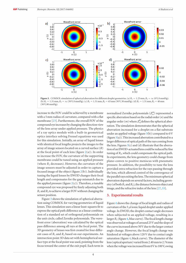
Figure 3 shows the simulation of spherical aberra-tion using COMSOL for varying geometries of liquid lenses. This simulation uses a linear least-squares fit to express the optical path difference as a linear combina-tion of a standard set of orthogonal polynomials on the unit circle, called Zernike polynomials. The wave-front error (aberration) was calculated by the optical pass difference among all rays at the focal point. The 3D geometry of lenses was first created for four differ-ent cases of R1 and R2 based on our experiments. An intersection point 3D data set with hemispherical sur-face type at the focal point was used, pointing from the focus toward the center of the exit pupil. Each term in
normalized Zernike polynomials (Znm) represented a
specific aberration based on the radial order (n) and the
angular order (m) where Z40 defines the spherical aber-
ration. The simulation demonstrates that the spherical aberration increased for a droplet on a flat substrate under an applied voltage (figure 3(b)) compared to 0 V (figure 3(a)). This increased aberration contributed to a larger difference of optical path of the rays coming from the lens. Figures 3(c) and (d) illustrate that the aberra-tion of an EWOD-actuated lens could be reduced by fine tuning of R2, which could compensate the optical path. In experiments, the lens geometry could change from plano-convex to positive meniscus with pneumatic pressure. In addition, the possibility to tune the lens provided extra refraction for the rays passing through the lens, which allowed control of the convergence of the parallel rays exiting the lens. The minimum spherical aberration depends on several factors, including geom-etry (of both R1 and R2), the distance between object and image, and the refractive index of the lens [27, 33].
3. Experimental results
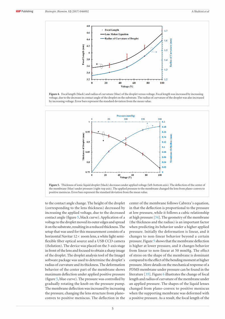
Figure 4 shows the change of focal length and radius of curvature of the 3 µl ionic liquid droplet under applied voltage. In EWOD, the droplet contact angle decreases when subjected to an applied voltage, resulting in a larger R1 (figure 4, blue curve). The focal length change was observed at voltages of around 25 V and the slope of the curve increased above 50 V due to the larger contact angle change. However, the focal length change was hindered at voltages above 120 V due to contact angle saturation (figure 4, black curve). The diameter of the lens (optical aperture) varied from 2.40 mm to 2.74 mm when the voltage was increased from 0 V to 100 V, owing
Figure 3. COMSOL simulation of spherical aberration for different droplet geometries. (a) R1 = 1.25 mm, R2 = ∞ (0 V, 0 mmHg). (b) R1 = 1.31 mm, R2 = ∞ (50 V, 0 mmHg). (c) R1 = 1.31 mm, R2 = 65 mm (50 V, 30 mmHg). (d) R1 = 1.31 mm, R2 = 40 mm (50 V, 80 mmHg).
Bioinspir. Biomim. 12 (2017) 046002
5
A Shahini et al
to the contact angle change. The height of the droplet (corresponding to the lens thickness) decreased by increasing the applied voltage, due to the decreased contact angle (figure 5, black curve). Application of a voltage to the droplet moved its outer edges and spread it on the substrate, resulting in a reduced thickness. The setup that was used for this measurement consists of a horizontal Navitar 12× zoom lens, a white light semi-flexible fiber optical source and a USB CCD camera (iSolution). The device was placed on the 3-axis stage in front of the lens and focused to obtain a sharp image of the droplet. The droplet analysis tool of the ImageJ software package was used to determine the droplet’s radius of curvature and its thickness. The deformation behavior of the center part of the membrane shows maximum deflection under applied positive pressure (figure 5, blue curve). The pressure was controlled by gradually rotating the knob on the pressure pump. The membrane deflection was increased by increasing the pressure, changing the lens structure from plano-convex to positive meniscus. The deflection in the
center of the membrane follows Cabrera’s equation, in that the deflection is proportional to the pressure at low pressure, while it follows a cubic relationship at high pressure [34]. The geometry of the membrane (the thickness and the radius) is an important factor when predicting its behavior under a higher applied pressure. Initially the deformation is linear, and it changes to non-linear behavior beyond a certain pressure. Figure 5 shows that the membrane deflection is higher at lower pressure, and it changes behavior from linear to non-linear at 50 mmHg. The effect of stress on the shape of the membrane is dominant compared to the effect of the bending moment at higher pressure. More details on the mechanical response of a PDMS membrane under pressure can be found in the literature [35]. Figure 6 illustrates the change of focal length and radius of curvature of the membrane under an applied pressure. The shapes of the liquid lenses changed from plano-convex to positive meniscus when the supporting membrane was deformed with a positive pressure. As a result, the focal length of the
Figure 4. Focal length (black) and radius of curvature (blue) of the droplet versus voltage. Focal length was increased by increasing voltage, due to the decrease in contact angle of the droplet on the substrate. The radius of curvature of the droplet was also increased by increasing voltage. Error bars represent the standard deviation from the mean value.
Figure 5. Thickness of ionic liquid droplet (black) decreases under applied voltage (left-bottom axis). The deflection of the center of the membrane (blue) under pressure (right-top axis). The applied pressure to the membrane changed the lens from plano-convex to positive meniscus. Error bars represent the standard deviation from the mean value.
Bioinspir. Biomim. 12 (2017) 046002

6
A Shahini et al
lens increased owing to the larger curvature of the membrane. With a thin micromachined membrane, our lens allows for fine tuning of the focal length (0.5% with 10 mmHg pressure), indicating its capability for aberration correction.
The imaging ability of our liquid lens was examined by acquiring the images of a 1951 USAF resolution chart (figures 7(a)–(d)). Figure 7(a) shows the image cap-tured through a plano-convex lens with no voltage or pressure applied. The value of R1 was 1.25 mm and the focal length was 3.57 mm, resulting in a magnification of 1.33. Elements 8 and 9 were focused as well as possi-ble in this picture. The image became blurred by EWOD actuation (50 V) of the droplet, owing to the larger focal length associated with a larger R1 (figure 7(b)). Here, R1
was 1.31 mm and the focal length was 3.74 mm, result-ing in a magnification of 1.35. Although a demagni-fied image was expected to be observed, the image was magnified, owing to the exceeded distance between the object and the primary principal plane (d0) of the lens which was dominant in determining the image com-pared to focal length. The object was focused again by changing the lens geometry to a positive meniscus with 30 mmHg of applied pressure (figure 7(c)). In this case R1 was 1.31 mm, R2 was 65 mm and the focal length was 3.78 mm, resulting in a magnification of 1.326. Apply-ing pressure to the system decreased d0 while increasing the focal length of the lens by increasing R2, resulting in a demagnification of the image. Figure 7(d) shows that by applying higher pressure, the resolution of the
Figure 6. Focal length (black) and radius of curvature (blue) of ionic liquid lens versus applied pressure. Focal length was increased by increasing pressure due to the change of lens geometry from plano-convex to positive meniscus. R2 was decreased by increasing pressure, resulting in more curvature of the lens. The experimental results are consistent with the lensmaker’s equation. Error bars represent the standard deviation from the mean value.
Figure 7. Images of an object taken by a liquid lens under varying voltages and pressures. (a) No voltage and no pressure applied. (b) At 50 V and no pressure, where the focal length increased and the image blurred. (c) At 50 V and 30 mmHg, where the object was brought into focus. (d) At 50 V and 80 mmHg, where the magnification changed and resolution improved.
Bioinspir. Biomim. 12 (2017) 046002

7
A Shahini et al
device was improved and the elements could be clearly resolved (by comparing the numbers 8 and 9 in the res-olution chart). Figure 8(a) shows the image of groups 8 and 9 of the 1951 USAF resolution chart taken by our liquid lens. The distance between the lens and the object was less than 1 mm, which makes the image of the object larger due to the virtual imaging concept. Element 3 of group 9 can be clearly visualized relative to a resolution of 645.1 lp mm−1. Based on the diffraction limit, the resolution of our lens with a focal length of 4.6 mm and an effective aperture diameter of 2.7 mm in visible light with a wavelength of 750 nm is 784.3 lp mm−1, which is calculated using the equations below [36]:
=f #effective focal length
effective optical aperture (2)
µµ
=
−
−
f
Diffraction limit lp mm
1000 m mm
# wavelength in m
1
1
( )
( )( ( )) (3)
This attribute permits the exceptionally high resolution images associated with positive meniscus geometry. The focusing power of the lens was examined under applied voltages by a real imaging configuration, using a Lego structure with a smiley face as the object (figure 8(b)). The Lego had two steps with 10 mm separation and the lens was placed 20 mm above the Lego. When no voltage was applied to the droplet (figure 8(b), left), the top smiley face was in focus while the bottom one was blurred. Applying a voltage to the electrodes increased the focal length of the lens and brought the bottom smiley face into focus (figure 8(b), right). In this
experiment the distance between the objective lens and the liquid lens was fixed (90 mm) and the voltage was changed from 0 V to 100 V.
Figure 9(a) demonstrates a prototype of the tunable compound eye with nine liquid lenses. The planar elec-trodes were designed such that the driving electrodes are interconnected while each lens has its own refer-ence electrodes [26]. The dark lines in the figure are the thin copper which was used for external connections. This design facilitated the application of voltage to individual lenses independently. Figure 9(b) shows that the bottom left lens (white dashed circle) was actuated while the other lenses remained constant. The num-ber 1 in the figure was magnified at 100 V owing to the larger focal length, when compared to that obtained at 0 V. The key feature of this design (individual control of the focal length) along with the simulation in figures 1 and 2 allow us to design a tunable compound eye with minimum aberration and no change in curvature of the supporting sensors. The least distance of distinct vision (LDDV) is the minimum distance that an object can be placed in front of a lens while still forming a distinct and clear image (also called the reference seeing distance (RSD)). The image of an object placed closer to a lens than the LDDV appears blurred and fuzzy. The LDDV for the image sensors located 4.57 mm below the com-pound eye presented here is around 15.7 mm. However, this number could vary based on the geometry of the lenses and the location of the image sensors.
Table 1 summarizes selected tunable lenses that have been reported in the literature. EWOD has been used to change the droplet curvature using a chamber with two
Figure 8. (a) Image of elements in groups 8 and 9 of the resolution chart, using liquid lens. Element 3 of group 9 could be resolved corresponding to a resolution of 645.1 lp mm−1. (b) Focal length tunability of our lens examined by acquiring images of the Lego object at varying distances from the lens. At 0 V (left), the top smiley face is clear and the bottom one is blurred. At 100 V (right), the bottom smiley face came into focus and the top one became blurred.
Bioinspir. Biomim. 12 (2017) 046002

8
A Shahini et al
immiscible liquids [15, 37]. Moran et al demonstrated a tunable lens using pressure to control the deforma-tion of the liquid interface [38], but the lens aperture was small, probably due to capillary pressure generated by high surface tension of the liquid. Liebetraut et al introduced elastomeric lenses by controlling the strain on flexible elastomer [39], but the design required sev-eral external servo motors for actuation. Electroactive elastomer was investigated by Shian et al to change the curvatures of lenses (R1 and R2) [40], but the transpar-ency of the lens was poor due to the additional elec-trodes. Pneumatic actuation has also been used to build a variable focal length lens for confocal endoscopy [41]. Wang et al demonstrated a compound eye with a large FOV, using a near-infrared actuation mechanism [13]. A tunable microlens array on a curved substrate was also demonstrated, using a thermo-responsive hydro-gel actuator [12]. Although the lens curvature could be tuned individually, the second curvature of the lens (R2) was fixed. Nevertheless, for all lenses summarized here either one curvature only could change or both cur-vatures would change simultaneously. The liquid lens
presented in this paper has several advantages, includ-ing the capability to change both curvatures indepen-dently, high resolution, and high imaging quality. Like all liquid lenses, ours has its limitations. Due to the higher viscosity of the ionic liquids, the response time of the device (150 ms) is expected to be slow compared to aqueous solutions such as KCl (50 ms). In addition, the actuation voltage (around 25 V) can limit the appli-cation of the device in conditions where low voltages are required. However, this could be improved using some dielectric materials with a higher dielectric constant,
such as polyvinylidene fluoride (PVDF).
4. Conclusions
In summary, the proposed lens system is a simple example of how changing R2 enabled us to acquire high image quality. A key defining attribute of the single lens system is its applicability in artificial compound eyes with larger numbers of autofocusing lenses. This design can open up new avenues in flexible technologies on transparent platforms for imaging and detection
Figure 9. (a) Prototype of compound eyes with 9 elemental lenses, and (b) individually tuning the lenses using applied voltage. At 100 V the bottom left droplet was changed and the image was magnified while the other lenses remained constant.
Table 1. Comparison between tunable lenses with different materials and actuation mechanisms.
Paper Curvature change Actuation Lens materials Focal length range (mm) Resolution (lp mm−1)
Berge and Peseux [15] R1 EWOD Water/Oil 9 …
Li and Jiang [37] R1 EWOD Water/Oil Infinity 25.39
Moran et al [38] R1 and R2 Pressure Water 4.6 …
Liebetraut et al [39] R1 and R2 Strain PDMS 2.3 …
Shian et al [40] R1 and R2 Electrical Electroactive elastomer >100% …
Kim et al [41] R1 Pneumatic PDMS/Water 0.28 228
Wang et al [13] R1 Pulsed laser Glycerol/Graphene 0.5 …
Zhu et al [12] R1 Thermal Water/Oil Infinity …
This work R1 and R2 EWOD Ionic liquid 4 >456.1
Bioinspir. Biomim. 12 (2017) 046002
9
A Shahini et al
purposes. In addition, the FOV of compound eye lenses could be increased by manipulating both R1 and R2 while the sensor’s location is fixed. The compatibility of graphene with the flexible and transparent elastomer provides the possibility of other applications to address some limitations associated with the materials. The proposed all-graphene liquid lens has several unique advantages including high transparency, light weight, high flexibility, high resolution, low spherical aberration and a large optical aperture. A promising topic for future work is to explore the application of this device in other areas, such as biology.
Acknowledgment
The authors thank Dr Yong Xu and Dr Eric Kim for their great help in parylene deposition. This work was carried out in nFAB at Wayne State University and was supported by NSF (#1055932).
References
[1] Dudley R 2002 The Biomechanics of Insect Flight: Form, Function, Evolution (Princeton, NJ: Princeton University Press)
[2] Warrant E and Nilsson D-E 2006 Invertebrate Vision (Cambridge: Cambridge University Press)
[3] Juusola M, Dau A, Song Z, Solanki N, Rien D, Jaciuch D, Dongre S, Blanchard F, de Polavieja G G, Hardie R C and Takalo J 2016 Microsaccadic information sampling provides Drosophila hyperacute vision bioRxiv 083691
[4] Franceschini N 1997 Combined optical, neuroanatomical, electrophysiological and behavioral studies on signal processing in the fly compound eye Biocybernetics of Vision: Integrative Mechanisms and Cognitive Processes (Singapore: World Scientific)
[5] Li L and Yi A Y 2010 Development of a 3D artificial compound eye Opt. Express 18 18125–37
[6] Song Y M, Xie Y, Malyarchuk V, Xiao J, Jung I, Choi K-J, Liu Z, Park H, Lu C, Kim R-H, Li R, Crozier K B, Huang Y and Rogers J A 2013 Digital cameras with designs inspired by the arthropod eye Nature 497 95–9
[7] Li Z and Xiao J 2015 Mechanics and optics of stretchable elastomeric microlens array for artificial compound eye camera J. Appl. Phys. 117 014904
[8] Liu H, Huang Y and Jiang H 2016 Artificial eye for scotopic vision with bioinspired all-optical photosensitivity enhancer Proc. Natl Acad. Sci. 113 3982–85
[9] Floreano D et al 2013 Miniature curved artificial compound eyes Proc. Natl Acad. Sci. 110 9267–72
[10]Jeong K-H, Kim J and Lee L P 2006 Biologically inspired artificial compound eyes Science 312 557–61
[11]Radtke D, Duparré J, Zeitner U D and Tünnermann A 2007 Laser lithographic fabrication and characterization of a spherical artificial compound eye Opt. Express 15 3067–77
[12]Zhu D, Li C, Zeng X and Jiang H 2010 Tunable-focus microlens arrays on curved surfaces Appl. Phys. Lett. 96 081111
[13]Wang L, Li F, Liu H, Jiang W, Niu D, Li R, Yin L, Shi Y and Chen B 2015 Graphene-based bioinspired compound eyes for programmable focusing and remote actuation ACS Appl. Mater. Interfaces 7 21416–22
[14]Mugele F and Baret J-C 2005 Electrowetting: from basics to applications J. Phys.: Condens. Matter 17 R705
[15]Berge B and Peseux J 2000 Variable focal lens controlled by an external voltage: An application of electrowetting Eur. Phys. J. E 3 159–63
[16]Hendriks B, Kuiper S, As M V, Renders C and Tukker T 2005 Electrowetting-based variable-focus lens for miniature systems Opt. Rev. 12 255–9
[17]Smith N R, Hou L, Zhang J and Heikenfeld J 2009 Fabrication and demonstration of electrowetting liquid lens arrays J. Disp. Technol. 5 411–3
[18]Kuiper S and Hendriks B 2004 Variable-focus liquid lens for miniature cameras Appl. Phys. Lett. 85 1128–30
[19]Liu C-X, Park J and Choi J-W 2008 A planar lens based on the electrowetting of two immiscible liquids J. Micromech. Microeng. 18 035023
[20]Ashtiani A O and Jiang H 2015 Design and fabrication of an electrohydrodynamically actuated microlens with areal density modulated electrodes J. Micromech. Microeng. 26 015004
[21]Tan X, Yang J, Zeng P, Kim E, Huard C and Cheng M 2012 Electrowetting on flexible, transparent and conducting single-layer graphene 2012 IEEE 25th Int. Conf. on Micro Electro Mechanical Systems (MEMS) (IEEE) pp 1037–40
[22]Tan X, Zhou Z and Cheng M M-C 2012 Electrowetting on dielectric experiments using graphene Nanotechnology 23 375501
[23]Shahini A, Xia J, Zhou Z, Zhao Y and Cheng M M-C 2016 Versatile miniature tunable liquid lenses using transparent graphene electrodes Langmuir 32 1658–65
[24]Wei K and Zhao Y 2013 A three-dimensional deformable liquid lens array for directional and wide angle laparoscopic imaging 2013 IEEE 26th Int. Conf. on Micro Electro Mechanical Systems (MEMS) (IEEE) pp 133–6
[25]Zhu D, Zeng X, Li C and Jiang H 2011 Focus-tunable microlens arrays fabricated on spherical surfaces J. Microelectromech. Syst. 20 389–95
[26]Shahini A, Zeng P, Zhao Y and Cheng M M-C 2016 Individually tunable liquid lens arrays using transparent graphene for compound eye applications 2016 IEEE 29th Int. Conf. on Micro Electro Mechanical Systems (MEMS) (IEEE) pp 597–600
[27]Meyer-Arendt J R 1989 Introduction to Classical and Modern Optics 3rd edn (Englewood Cliffs, NJ: Prentice-Hall)
[28]Armand M, Endres F, MacFarlane D R, Ohno H and Scrosati B 2009 Ionic-liquid materials for the electrochemical challenges of the future Nat. Mater. 8 621–9
[29]Garcia B, Lavallée S, Perron G, Michot C and Armand M 2004 Room temperature molten salts as lithium battery electrolyte Electrochim. Acta 49 4583–8
[30]Starovoytov O N, Torabifard H and Cisneros G A S 2014 Development of amoeba force field for 1, 3-dimethylimidazolium based ionic liquids J. Phys. Chem. B 118 7156–66
[31]Sato T, Masuda G and Takagi K 2004 Electrochemical properties of novel ionic liquids for electric double layer capacitor applications Electrochim. Acta 49 3603–11
[32]Hecht E 1987 Optics vol 1, 2nd edn, ed E Hecht (Reading, MA: Addison-Wesley)
[33]Jenkins F A and White H E 1976 Fundamentals of Optics vol 1, 4th edn, ed F A Jenkins and H E White (New York: McGraw-Hill)
[34]Schomburg W K 2015 Introduction to Microsystem Design (Berlin: Springer)
[35]Li Z, Wang Y and Xiao J 2016 Mechanics of bioinspired imaging systems Theor. Appl. Mech. Lett. 6 11–20
[36]Edmund Optics Diffraction Limit (https://www.edmundoptics.com/resources/application-notes/imaging/diffraction-limit/)
[37]Li C and Jiang H 2012 Electrowetting-driven variable-focus microlens on flexible surfaces Appl. Phys. Lett. 100 231105
[38]Moran P M, Dharmatilleke S, Khaw A H, Tan K W, Chan M L and Rodriguez I 2006 Fluidic lenses with variable focal length Appl. Phys. Lett. 88 041120
[39]Liebetraut P, Petsch S, Liebeskind J and Zappe H 2013 Elastomeric lenses with tunable astigmatism Light: Sci. Appl. 2 e98
[40]Shian S, Diebold R M and Clarke D R 2013 Tunable lenses using transparent dielectric elastomer actuators Opt. Express 21 8669–76
[41]Kim M, Kang D, Wu T, Tabatabaei N, Carruth R W, Martinez R V, Whitesides G M, Nakajima Y and Tearney G J 2014 Miniature objective lens with variable focus for confocal endomicroscopy Biomed. Opt. Express 5 4350–61
Bioinspir. Biomim. 12 (2017) 046002