Embed Size (px)
Citation preview

TOXOTES MICRO STEPPER
CNC Stepper Motor Controller
Western Robotics Ltd.
1/9/2012

Toxotes Hardware Reference Guide PCB Rev 1.1 Page 2
Table of Contents
1.0 FEATURES .................................................................................................................................... 3
2.0 HARDWARE LAYOUT .................................................................................................................... 4
3.0 QUICK SETUP GUIDE PROCEDURE................................................................................................. 5
4.0 SELECTING/CONNECTING STEPPER MOTORS ................................................................................ 5
4.1 6 & 8 Wire Stepper Motors .................................................................................................................... 5
4.1.1 6 Wire Stepper Wiring Diagram ..................................................................................................... 6
4.1.1.1 Bipolar Series Connection .............................................................................................................. 6
4.1.1.2 Unipolar Connection ...................................................................................................................... 7
4.1.2 8 Wire Stepper Motor Wiring Diagram ........................................................................................... 7
4.1.2.1 Bipolar Series Connection ............................................................................................................ 7
4.1.2.2 Bipolar Parallel Connection ......................................................................................................... 8
4.1.2.3 Unipolar Connection .................................................................................................................... 9
4.2 4 Wire Stepper Motor ........................................................................................................................... 9
5.0 HARDWARE PORT DESCRIPTION ................................................................................................. 10
5.1 Parallel Port, Limit Switch Input & Output Port Connection ................................................................. 10
5.1.1 Limit Switch Input ............................................................................................................................ 11
5.3 Step Resolution Setting ....................................................................................................................... 11
5.4 Power Input ........................................................................................................................................ 12
5.5 Motor Current Adjust .......................................................................................................................... 12
5.6 Percent Fast Decay (PFD) Adjust .......................................................................................................... 13
5.7 Stepper Motor Connection Ports ......................................................................................................... 14
6.0 ADDITIONAL SAFETY NOTES ....................................................................................................... 14
7.0 WARRANTY & LIABILITY .............................................................................................................. 15

Toxotes Hardware Reference Guide PCB Rev 1.1 Page 3
1.0 FEATURES
• 4, 5 or 6 Axis Bi-Polar Stepper Motor Controller
• Programmable motor step resolution of full, ½, ¼ or 1/16 step
• High current capability of up to 2.5 Amperage per axis (per motor)
• Wide input power range to handle 8 to 30 Volts rating stepper motors
• Personal Computer (PC) interfaced via on board Parallel Port
• Compatible with market available Computerized Numeric Control (CNC) PC interface software
• Uses Pulse Width Modulation technology (chopper) for improved power dissipation
• On board adjustable stepper motor current setting via potentiometer
• On board adjustable PFD (Percent Fast Decay)
• Limit switch input PC controlled via parallel port
• Noise reduction filter on each input and output. (Output port not available on 6 Axis model)
• Compatible with 4, 6 and 8 wire (NEMA 17, NEMA 23 and NEMA 34) stepper motors
NEMA17
NEMA23 NEMA34
Example Motor Types

Toxotes Hardware Reference Guide PCB Rev 1.1 Page 4
2.0 HARDWARE LAYOUT
Please read the entire manual before proceeding to operate the Toxotes.
CAUTION! Before connecting stepper motor make sure the stepper motors are wired correctly. Ensure
the motor leads are securely attached. Intermittent or loose connections can generate several kilo volts
of back EMF spikes from the attached motors; this will result in possible damage to the motor and the
Toxotes CNC controller.
Layout diagram below illustrates all the user interfaces to configure the stepper motor settings, motor ports,
setup port connections to the PC controls and power connections for the 4 & 5 Axis controller board.
Power Input
10 to 24volt
PFD (Percent
Fast Decay)
Adjust / Axis
Motor Current
Adjust / Axis
Limit Switch
Input
Output Control
Port (4/5 axis
versions only)
Step Resolution
Settings / Axis
Y Axis
X Axis
Parallel Port
to PC
Stepper Motor
Connection Ports
A Axis
Z Axis
B Axis Auxiliary 5
Volt Supply
T Axis (not
shown, 6 axis
version only)

Toxotes Hardware Reference Guide PCB Rev 1.1 Page 5
3.0 QUICK SETUP GUIDE PROCEDURE
1. Ground yourself with the use of grounding wrist band.
2. Setup output pin configuration on chosen control software.
3. Connect 1 Stepper motor.
4. Connect power supply.
5. Turn power on to confirm correct connection of stepper wires - motor should lock up (if not, re-examine
stepper motor wiring diagram and re-wire)
6. Turn power off.
7. Connect remaining stepper motors.
8. Connect signal wires between computer and drive board.
9. Turn power on.
10. Attempt to jog axis with software (if axis turns in opposite direction of desired direction)
11. Attempt axis rotation reversal via software- if unable to do so switch 2 wires for one coil (i.e. switch A
with A#, do not switch wires between coils, please refer to the wiring diagrams in the manual)
12. You are now done and able to begin using your new stepper motor drive
4.0 SELECTING/CONNECTING STEPPER MOTORS
CAUTION! Incorrect wiring of the stepper motor to the Toxotes board may lead to permanent damage to
the Toxotes driver board. DO NOT CONNECT OR DISCONNECT MOTORS WHILE THE POWER IS APPLIED. It is
critical to obtain a proper motor coil diagram of your intended motor to be used with the Toxotes. Ensure
that the proper coil end wiring is properly connected to the Toxotes Axis ports, making improper connections
such as mixed cross connections on the stepper motor’s coils will destroy the Toxotes’ control circuitry.
The Toxotes Micro stepper CNC Controller is compatible with all 4, 6, and 8 wire stepper motors. It is
possible to drive these 3 different types of wired stepper motors having the motors to be rated ideally at 2.0
amps. Choosing a motor with a 1.8 degree per step resolution is recommended and is usually an industry
standard for CNC and motor automation applications.
The Toxotes driver is based on DMOS technology and despite the fact it features output protection it will be
damaged if it is not properly connected to the motor(s). Please following the 4, 6 & 8 Wire Stepper Motor
sections thoroughly before proceeding to operate the Toxotes with stepper motors connected. Note not to
connect ANY MOTOR leads directly to the ground or power supply to prevent possible damage to the
motors.
4.1 6 & 8 Wire Stepper Motors
If a 6 or 8 wire stepper motor is being used, consider them to be connected in a series wiring method. In
this case, when selecting these motors you must select the amperage rating to be doubled of that on the
motors labeled amperage rating. For example, selecting a 6 wire configured stepper motor, you will
need to select a 4 amp labeled motor, in actual fact this will result in an ideal 2 amp rating for your
Toxotes application.
Toxotes Hardware Reference Guide PCB Rev 1.1 Page 6
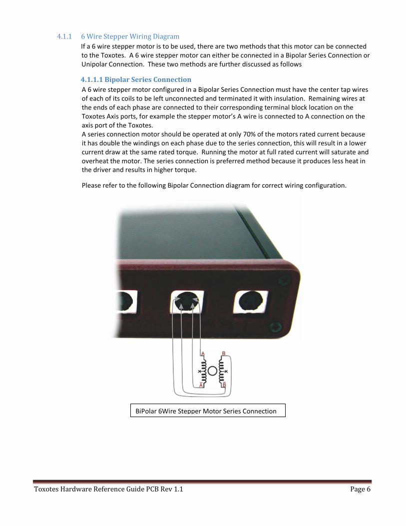
4.1.1 6 Wire Stepper Wiring Diagram
If a 6 wire stepper motor is to be used, there are two methods that this motor can be connected
to the Toxotes. A 6 wire stepper motor can either be connected in a Bipolar Series Connection or
Unipolar Connection. These two methods are further discussed as follows
4.1.1.1 Bipolar Series Connection
A 6 wire stepper motor configured in a Bipolar Series Connection must have the center tap wires
of each of its coils to be left unconnected and terminated it with insulation. Remaining wires at
the ends of each phase are connected to their corresponding terminal block location on the
Toxotes Axis ports, for example the stepper motor’s A wire is connected to A connection on the
axis port of the Toxotes.
A series connection motor should be operated at only 70% of the motors rated current because
it has double the windings on each phase due to the series connection, this will result in a lower
current draw at the same rated torque. Running the motor at full rated current will saturate and
overheat the motor. The series connection is preferred method because it produces less heat in
the driver and results in higher torque.
Please refer to the following Bipolar Connection diagram for correct wiring configuration.
BiPolar 6Wire Stepper Motor Series Connection

Toxotes Hardware Reference Guide PCB Rev 1.1 Page 7
4.1.1.2 Unipolar Connection
A 6 wire stepper motor configured in a unipolar connection has one end of each phase should be
unconnected and insulated. The other end and center tap are connected to their corresponding
terminal block location on the Toxotes Axis ports. In this case the attached motor could run at its
full current rating. This type of connection works better at higher RPM speeds.
Please refer to the following Unipolar Connection diagram for correct wiring configuration.
4.1.2 8 Wire Stepper Motor Wiring Diagram
If an 8 wire stepper motor is to be used, there are three methods that this motor can be connected to
the Toxotes. An 8 wire stepper motor can either be connected in a Bipolar Series Connection, Bipolar
Parallel Connection or Unipolar Connection. These three methods are further discussed as follows.
4.1.2.1 Bipolar Series Connection
An 8 wire stepper motor configured in a bipolar-series connection gives more torque at lower
RPM speeds and less torque at higher RPM speeds. A series connection motor should be
operated at only 70% of the motors rated current because it has double the windings on each
phase due to the series connection, this will result in a lower current draw at the same rated
torque. Running the motor at full rated current will saturate and overheat the motor.
UniPolar 6Wire Stepper Motor Connection

Toxotes Hardware Reference Guide PCB Rev 1.1 Page 8
Please refer to the following Bipolar Series Connection diagram for correct wiring configuration.
4.1.2.2 Bipolar Parallel Connection
An 8 wire stepper motor configured in a bipolar-parallel connection should run at 1.41 rated
current. This connection is not recommended because higher current is generated in this
configuration that will result in more heat buildup in the Toxotes driver and it’s connected motor.
Please refer to the following Bipolar Parallel Connection diagram for correct wiring configuration.
Bipolar 8 Wire Stepper Motor Series Connection
Bipolar 8 Wire Stepper Motor Parallel Connection

Toxotes Hardware Reference Guide PCB Rev 1.1 Page 9
4.1.2.3 Unipolar Connection
An 8 wire stepper motor configured in a unipolar connection has only one pair of each phase is
used. This connection works better at higher RPM speeds. Please refer to the following Unipolar
Connection diagram for correct wiring configuration.
4.2 4 Wire Stepper Motor
If a 4 wire stepper motor is to be used, then a motor rated from 2 to 2.5 amps per phase will yield the best
performance with the Toxotes micro stepper driver. The 4 wire configuration on these motors can only be
configured in one way and it connects directly to the motor axis port on the Toxotes. Each wire is connected
to its corresponding terminal block location example the stepper motor’s A wire is connected to the A
connection on the axis port of the Toxotes. If the rotation of the attached stepper motor turns the opposite
of the desired direction, then swapping the wires of just one phase will cause the motor to rotate in opposite
direction.
Unipolar 8 Wire Stepper Motor Connection
4 Wire Stepper Motor Connection

Toxotes Hardware Reference Guide PCB Rev 1.1 Page 10
5.0 HARDWARE PORT DESCRIPTION
This section describes all user interface ports on the Toxotes driver board as shown on section 2.0
Hardware Layout.
5.1 Parallel Port, Limit Switch Input & Output Port Connection
A DB25 male to female extension should be used to interconnect the driver board to your PC. This
connection does not require any kind of adaptors or hubs. The use of adapters and hubs is not
recommended and will prevent communication problems between the PC and Toxotes controller.
It is critical that the connection between the computer parallel port and motor driver board be direct
without the use of adapters. If your computer does not feature a 25 pin parallel port such as a laptop
computer, you must install one by adding a PMCIA card.
The following table labels all the corresponding PC DB25 parallel port pins with respect with the Toxotes
DB25 parallel port pins. Limit Switch Input and Output Control Port from the Toxotes board reflects the
same pin connections as the DB25 Parallel port Input and Output pins as displayed below.
Categorized Printer Port Pins:
DB25 PC Printer Port Output Pin from PC to TOXOTES Input Pin from TOXOTES to PC
1 Direction B Axis
2 Direction X Axis
3 Step X Axis
4 Direction Y Axis
5 Step Y Axis
6 Direction Z Axis
7 Step Z Axis
8 Direction A Axis
9 Step A Axis
10 HOME B
11 HOME A
12 HOME X
13 HOME Y
14 Step B Axis
15 HOME Z
16 Output 1 or Direction T Axis
17 Output 2 or Step T Axis
18-to-25 GROUND GROUND

Toxotes Hardware Reference Guide PCB Rev 1.1 Page 11
o Blue pins represent output control signals to the Toxotes Micro stepper CNC controller.
o Red pins represent input control signals for the limit and home switch.
o Green pins represent ground.
5.1.1 Limit Switch Input
The Limit Switch Input allows you to add end and home switches to your CNC application. Total
of 5 switches can be added to limit your movement of the CNC motion controlled by the stepper
motors. Refer to diagram below on the switch connection on the Limit Switch Input port on the
Toxotes board.
NOTE: OUTPUT PORTS NOT AVAILABLE ON 6 AXIS MODEL
Toxotes Hardware Reference Guide PCB Rev 1.1 Page 12
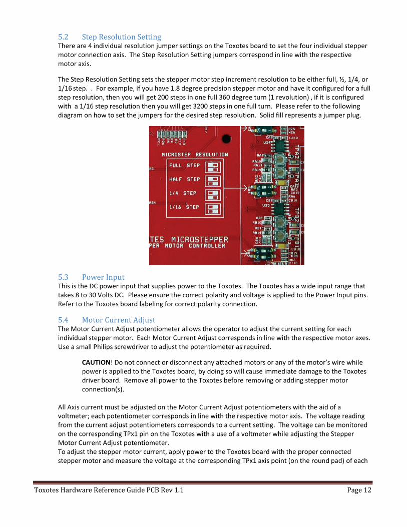
5.2 Step Resolution Setting There are 4 individual resolution jumper settings on the Toxotes board to set the four individual stepper
motor connection axis. The Step Resolution Setting jumpers correspond in line with the respective
motor axis.
The Step Resolution Setting sets the stepper motor step increment resolution to be either full, ½, 1/4, or
1/16 step. . For example, if you have 1.8 degree precision stepper motor and have it configured for a full
step resolution, then you will get 200 steps in one full 360 degree turn (1 revolution) , if it is configured
with a 1/16 step resolution then you will get 3200 steps in one full turn. Please refer to the following
diagram on how to set the jumpers for the desired step resolution. Solid fill represents a jumper plug.
5.3 Power Input This is the DC power input that supplies power to the Toxotes. The Toxotes has a wide input range that
takes 8 to 30 Volts DC. Please ensure the correct polarity and voltage is applied to the Power Input pins.
Refer to the Toxotes board labeling for correct polarity connection.
5.4 Motor Current Adjust The Motor Current Adjust potentiometer allows the operator to adjust the current setting for each
individual stepper motor. Each Motor Current Adjust corresponds in line with the respective motor axes.
Use a small Philips screwdriver to adjust the potentiometer as required.
CAUTION! Do not connect or disconnect any attached motors or any of the motor’s wire while
power is applied to the Toxotes board, by doing so will cause immediate damage to the Toxotes
driver board. Remove all power to the Toxotes before removing or adding stepper motor
connection(s).
All Axis current must be adjusted on the Motor Current Adjust potentiometers with the aid of a
voltmeter; each potentiometer corresponds in line with the respective motor axis. The voltage reading
from the current adjust potentiometers corresponds to a current setting. The voltage can be monitored
on the corresponding TPx1 pin on the Toxotes with a use of a voltmeter while adjusting the Stepper
Motor Current Adjust potentiometer.
To adjust the stepper motor current, apply power to the Toxotes board with the proper connected
stepper motor and measure the voltage at the corresponding TPx1 axis point (on the round pad) of each

Toxotes Hardware Reference Guide PCB Rev 1.1 Page 13
potentiometer with respect to the black or negative point of the Power supply GND. Please refer to the
following example diagram that shows where to measure the voltage points with Y AXIS of the Toxotes
board.
Use the following formula to translate the voltage reading to a current setting.
Vref = 2*(DESIRED CURRENT), therefore DESIRED CURRENT (A) = Vref/2
For example, for a desired current of 1.8 Amp you will adjust the V-REF potentiometer until you get the
3.6volt.
CAUTION! It is proper and safe to adjust the V-REF potentiometer while the power is applied to
the Toxotes board with the stepper motor properly connected. Make sure to adjust the
potentiometer slowly to slowly increase/decrease the current setting. If you find the motor is
overheating, this means that the motor current is too high and should be set lower.
It is recommended to use a series configured wiring if 6 or 8 wire motors are used. This reduces
the amperage rating by 50%. A 3 Amp motor wired in this way should consider as a 1.5amp
motor.
5.5 Percent Fast Decay (PFD) Adjust It is possible that the attached stepper motors on the Toxotes board to produce a high pitched resonance
noise; this is normal and is caused by the current pulse control circuitry. This is imperceptible in high
quality motors. It is possible to reduce the resonance noise by adjusting the Toxotes’ Percent Fast
Decay(PFD) adjust potentiometer as shown on the Hardware Layout section 2.0. The PFD adjust sets the
Toxotes driver output current decay when the PWM circuit switches the control current.
The PFD voltage can be monitored with the aid of a voltmeter by measuring the voltage at the
corresponding labeled TPx2 axis point (on the round pad) of each potentiometer with respect to the
Example Voltage Measuring Points for Current Adjust

Toxotes Hardware Reference Guide PCB Rev 1.1 Page 14
black or negative point of the Power supply GND. Please refer to the following example diagram that
shows where to measure the voltage points with one of the Toxotes board. For most stepper motors,
setting the PFD to 2.5VDC is a good reference to start point for minimal resonance noise
NOTE: It is proper and safe to adjust the PFD voltage while the power is applied to the Toxotes board
having the stepper motors properly connected.
5.6 Stepper Motor Connection Ports All stepper motor connections are made to the 4, 5 and 6 Axis connections on the Toxotes board as
shown on section 2.0 Hardware Layout. The corresponding X, Y, Z, A, B and T axis are as displayed on the
Hardware Layout diagram. These ports are controlled by the corresponding axis as in the PC CNC
software. Refer to section 3.1 and 3.2 for the proper stepper motor wiring.
6.0 ADDITIONAL SAFETY NOTES Always properly ground one-self when handling the Toxotes stepper motor drive board. It is highly
recommend that the stepper motor driver board is properly enclosed in an instrument case before use
(contact with debris may cause damage to the board). Do not connect or disconnect any attached motors
or any of the motor’s wire while power is applied to the Toxotes board, by doing so will cause immediate
damage to the Toxotes driver board. Remove all power to the Toxotes before removing or adding
stepper motor connection(s).
Example Voltage Measuring Points for PFD Adjust

Toxotes Hardware Reference Guide PCB Rev 1.1 Page 15
7.0 WARRANTY & LIABILITY
Disclaimer and Limitation of Liability
Western Robotics Ltd. shall have no liability or responsibility to the user of any other party or entity with respect
to any liability, injuries, loss or damage, cause or alleged to be caused, directly or indirectly, for equipment sold,
furnished or supplied by Western Robotics Ltd.
Notwithstanding the above limitations, Western Robotics Ltd. is not liable for damages incurred by customers or
to the customers. Western Robotics Ltd. is not liable for the particular equipment involved.
Neither Western Robotics Ltd. nor this document makes any expressed or implied warranty, including, but not
limited to the implied warranties of merchantability, quality or fitness for a particular purpose.
Specifications are subject to change without notice.
Limited Warranty (North America Only)
The TOXOTES MICROSTEPPER is guaranteed to be free from defects in material and workmanship for a period of
90 days from the date of purchase accompanied by the proof of purchase or invoice. Warranty does not cover
damage due to improper use or incorrect installation.
During the 90 day warranty period, if the product shows defects caused by abuse, accident or misuse, it will
repaired or replaced upon Western Robotics Ltd. sole discretion, at a service charge not greater than 40% of the
current retail list price. Please ensure to include your contact information before any repair(s) or replacement(s)
can be conducted. Under no circumstances or condition will the purchaser be entitled to consequential or
incidental damages. In no case shall our liability exceed the product's original cost. We reserve the right to
modify warranty provision without notice. Because Western Robotics Ltd. has no control over connection and
use of this product, no liability may be assumed nor will be accepted for damage resulting from the use of this
product, user accepts all resulting liability. If you attempt to disassemble, modify or repair this unit yourself, it
may void the warranty.
For warranty service on Western Robotics product(s) in, out or off warranty period, please send the defective
unit(s) along with the proof of purchase and a description of the problem, postage paid, to the given address
below.
Customer Service,
Western Robotics Ltd.
215-12837 76th Avenue
Surrey, BC
V3W 2V3 Canada
Phone: 778-565-1332
www.western-robotics.com