Embed Size (px)
Citation preview
TOYOTA COROLLA 2009- HANDS FREE BLU LOGICPreparation
Page 1 of 14Issue B : 01/22/09
Part #: PT923-00090 NOTE: Part number of this accessory may not be the same as the part number shown.
Conflicts: JBL Audio
Kit Contents:
Hardware Content
Item# Quanity Reqd. Description
1 1 Interface Module2 1 Main Power Harness3 1 3 Button Switch4 1 Microphone5 10 9.5” Lock Ties6 1 Microphone Tape7 1 Owner’s Manual8 33cm Wire Split Loom
Additional Items (may be required)
Item# Quanity Reqd. Description
Recommended Sequence of Application
Item# Quanity Reqd. Description
Item 1
Vehicle Service Parts (may be required for reassembly)
Item# Quanity Reqd. Description
Item 2 Item 3
General Applicability
Note:Recommended Tools
Personal & Vehicle Protection Notes
Safety Goggles
Seat Covers
Floor Covers
Special Tools
Panel Clip Removal SST # 00002-06001-01
Sockets 10 mm
Screwdriver Phillips, #2
Side Cutters
Torque Wrench 36 in.lbf (4.07 N.m)
Installation Tools Notes
Foam Tape VDC Supplied
Masking Tape VDC Supplied
Special Chemicals
Cleaner VDC Approved Cleaner
LegendSTOP:Damage to the vehicle may occur. Do not proceed until pro-cess has been complied with.
CAUTION: A process that must be carefully observed in order to reduce the risk of damage to the accessory/vehicle.
OPERATOR SAFETY: Use caution to avoid risk of injury.
TOOLS & EQUIPMENT: Used in Figures to call out the specific tools and equipment recommended for the process.
REVISION MARK: This mark highlights a change in installation with respect to previous issue.
SAFETY TORQUE: This mark indicates that torque is related to safety.
VIDEO: Video Available; click to Play
Item 4 Item 5 Item 6 Item 7
TOYOTA COROLLA 2009- HANDS FREE BLU LOGICPreparation
Page 2 of 14Issue B : 01/22/09
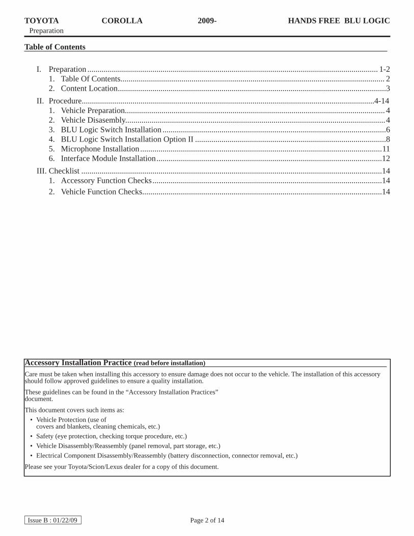
Table of Contents
PreparationI. ............................................................................................................................................... 1-2Table Of Contents..................................................................................................................................1. 2Content Location2. ....................................................................................................................................3
Procedure................................................................................................................................................4-14II. Vehicle Preparation................................................................................................................................1. 4Vehicle Disasembly................................................................................................................................2. 4BLU Logic Switch Installation3. ..............................................................................................................6BLU Logic Switch Installation Option II4. ..............................................................................................8Microphone Installation5. .......................................................................................................................11Interface Module Installation6. ...............................................................................................................12
ChecklistIII. ....................................................................................................................................................14Accessory Function Checks1. .................................................................................................................14Vehicle Function Checks2. ......................................................................................................................14
Accessory Installation Practice (read before installation)Care must be taken when installing this accessory to ensure damage does not occur to the vehicle. The installation of this accessory should follow approved guidelines to ensure a quality installation.
These guidelines can be found in the “Accessory Installation Practices” document.
This document covers such items as:Vehicle Protection (use of •covers and blankets, cleaning chemicals, etc.)Safety (eye protection, checking torque procedure, etc.)•Vehicle Disassembly/Reassembly (panel removal, part storage, etc.)•Electrical Component Disassembly/Reassembly (battery disconnection, connector removal, etc.)•
Please see your Toyota/Scion/Lexus dealer for a copy of this document.
TOYOTA COROLLA 2009- HANDS FREE BLU LOGICPreparation
Page 3 of 14Issue B : 01/22/09
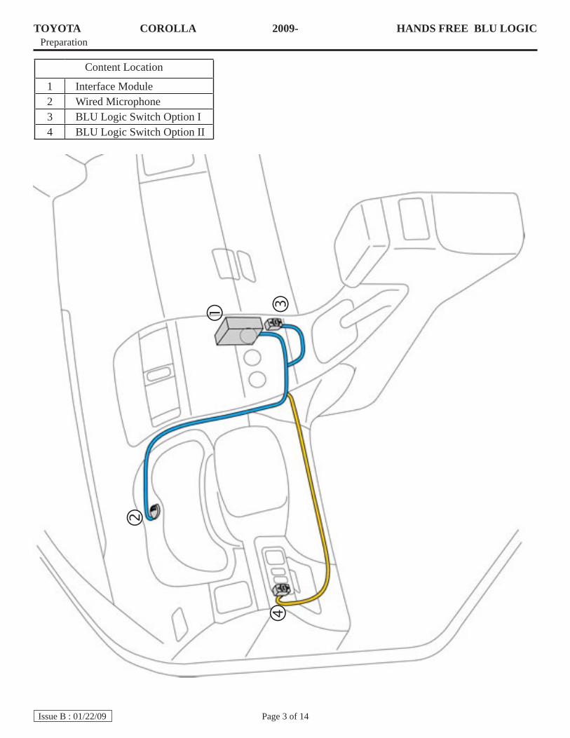
Content Location
1 Interface Module2 Wired Microphone3 BLU Logic Switch Option I4 BLU Logic Switch Option II
TOYOTA COROLLA 2009 - HANDS FREE BLU LOGICProcedure
Page 4 of 14Issue B : 01/22/09
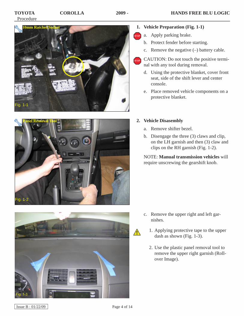
Vehicle 1. Preparation (Fig. 1-1)
Apply parking brake.a. Protect fender before starting.b. Remove the negative (–) battery cable.c.
CAUTION: Do not touch the positive termi-nal with any tool during removal.
Using the protective blanket, cover front d. seat, side of the shift lever and center console.Place removed vehicle components on a e. protective blanket.
Fig. 1-1
Remove the upper right and left gar-c. nishes.
Applying protective tape to the upper 1. dash as shown (Fig. 1-3).
Use the plastic panel removal tool to 2. remove the upper right garnish (Roll-over Image).
Vehicle2. Disasembly
Remove shifter bezel.a. Disengage the three (3) claws and clip, b. on the LH garnish and then (3) claw and clips on the RH garnish (Fig. 1-2).
NOTE: Manual transmission vehicles will require unscrewing the gearshift knob.
Panel Removal Tool
Fig. 1-2
10mm Ratchet/Socket
TOYOTA COROLLA 2009 - HANDS FREE BLU LOGICProcedure
Page 5 of 14Issue B : 01/22/09
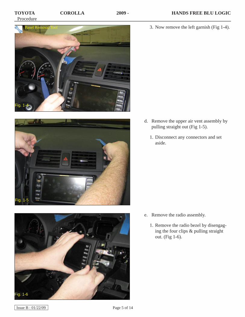
Now remove the left garnish (Fig 1-4).3.
Fig. 1-4
Remove the radio assembly.e.
Remove the radio bezel by disengag-1. ing the four clips & pulling straight out. (Fig 1-6).
Remove the upper air vent assembly by d. pulling straight out (Fig 1-5).
Disconnect any connectors and set 1. aside.
Fig. 1-5
Panel Removal Tool
Fig. 1-6
TOYOTA COROLLA 2009 - HANDS FREE BLU LOGICProcedure
Page 6 of 14Issue B : 01/22/09
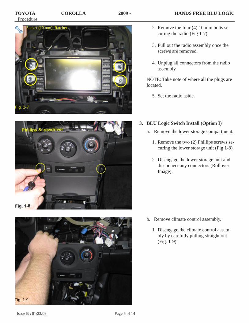
Remove the four (4) 10 mm bolts se-2. curing the radio (Fig 1-7).
Pull out the radio assembly once the 3. screws are removed.
Unplug all connectors from the radio 4. assembly.
NOTE: Take note of where all the plugs are located.
Set the radio aside. 5.
Fig. 1-7
BLU Logic Switch Install (Option I)3.
Remove the lower storage compartment.a.
Remove the two (2) Phillips screws se-1. curing the lower storage unit (Fig 1-8).
Disengage the lower storage unit and 2. disconnect any connectors (Rollover Image).
Socket (10 mm), Ratchet
Fig. 1-9
Remove climate control assembly.b.
Disengage the climate control assem-1. bly by carefully pulling straight out (Fig. 1-9).
TOYOTA COROLLA 2009 - HANDS FREE BLU LOGICProcedure
Page 7 of 14Issue B : 01/22/09
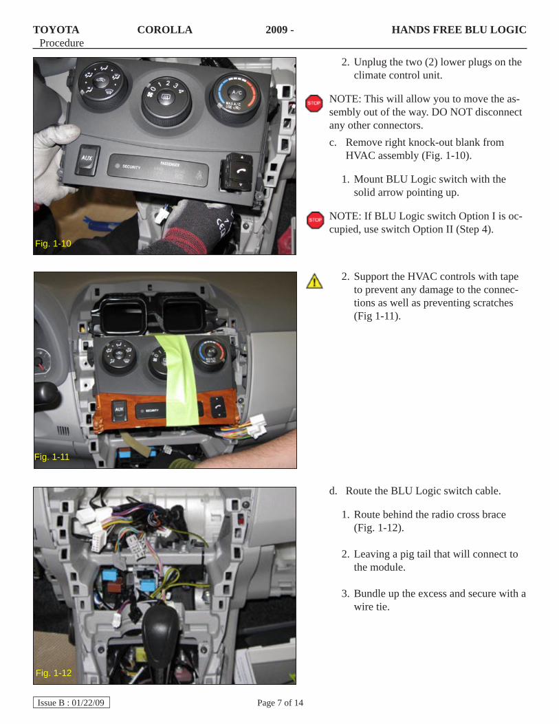
Unplug the two (2) lower plugs on the 2. climate control unit.
NOTE: This will allow you to move the as-sembly out of the way. DO NOT disconnect any other connectors.
Remove right knock-out blank from c. HVAC assembly (Fig. 1-10).
Mount BLU Logic switch with the 1. solid arrow pointing up.
NOTE: If BLU Logic switch Option I is oc-cupied, use switch Option II (Step 4).
Fig. 1-10
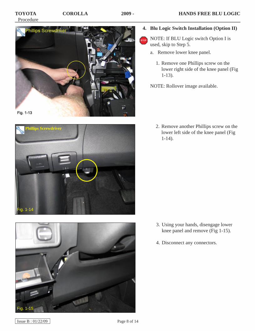
Route the BLU Logic switch cable.d.
Route behind the radio cross brace 1. (Fig. 1-12).
Leaving a pig tail that will connect to 2. the module.
Bundle up the excess and secure with a 3. wire tie.
Support the HVAC controls with tape 2. to prevent any damage to the connec-tions as well as preventing scratches (Fig 1-11).
Fig. 1-11
Fig. 1-12
TOYOTA COROLLA 2009 - HANDS FREE BLU LOGICProcedure
Page 8 of 14Issue B : 01/22/09
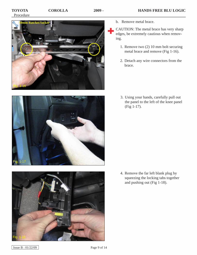
Blu Logic Switch Installation (Option II) 4.
NOTE: If BLU Logic switch Option I is used, skip to Step 5.
Remove lower knee panel.a.
Remove one Phillips screw on the 1. lower right side of the knee panel (Fig 1-13).
NOTE: Rollover image available.
Remove another Phillips screw on the 2. lower left side of the knee panel (Fig 1-14).
Fig. 1-15
Using your hands, disengage lower 3. knee panel and remove (Fig 1-15).
Disconnect any connectors. 4.
Fig. 1-14
Phillips Screwdriver
TOYOTA COROLLA 2009 - HANDS FREE BLU LOGICProcedure
Page 9 of 14Issue B : 01/22/09
Fig. 1-16
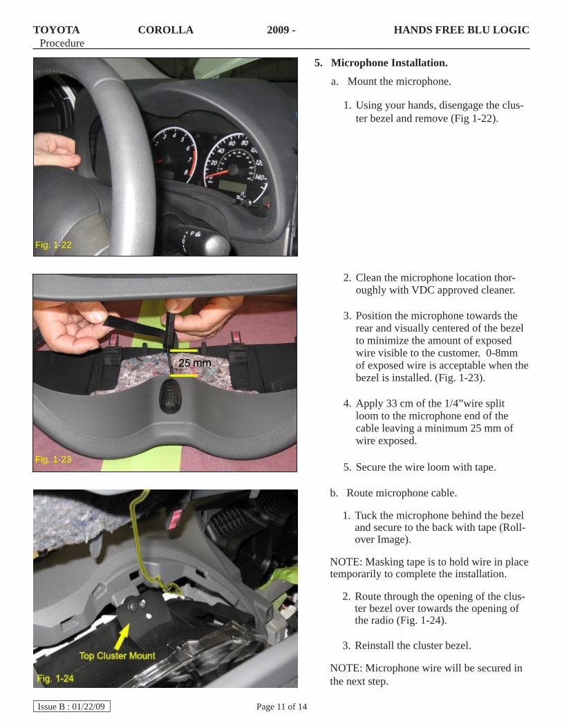
Using your hands, carefully pull out 3. the panel to the left of the knee panel (Fig 1-17).
Remove metal brace.b.
CAUTION: The metal brace has very sharp edges, be extremely cautious when remov-ing.
Remove two (2) 10 mm bolt securing 1. metal brace and remove (Fig 1-16).
Detach any wire connectors from the 2. brace.
Fig. 1-17
Remove the far left blank plug by 4. squeezing the locking tabs together and pushing out (Fig 1-18).
Fig. 1-18
10mm Ratchet/Socket

TOYOTA COROLLA 2009 - HANDS FREE BLU LOGICProcedure
Page 10 of 14Issue B : 01/22/09
Mount the BLU Logic switch (Fig. c. 1-19).
Make sure the solid arrow is pointing 1. up (Rollover Image).
NOTE: If far left blank plug is occupied, use next available blank plug location.
Route the switch cable. d.
Route along existing wire loom to-1. wards knee opening (Fig. 1-20).
Wire tie every 5-6 inches.2.
Cut off excess wire ties. 3.
Secure to existing wire loom with a 4. wire tie and continue routing towards radio opening (Fig 1-21).
Wire tie every 5-6 inches. 5.
NOTE: Telescope steering wheel to verify wires won’t be pulled or stretched.
Cut off excess wire ties.6.
Reinstall left hand switch panel, metal e. brace then knee panel.
Fig. 1-21
Fig. 1-20
Side Cutter
Side Cutter
TOYOTA COROLLA 2009 - HANDS FREE BLU LOGICProcedure
Page 11 of 14Issue B : 01/22/09
Clean the microphone location thor-2. oughly with VDC approved cleaner.
Position the microphone towards the 3. rear and visually centered of the bezel to minimize the amount of exposed wire visible to the customer. 0-8mm of exposed wire is acceptable when the bezel is installed. (Fig. 1-23).
Apply 33 cm of the 1/4”wire split 4. loom to the microphone end of the cable leaving a minimum 25 mm of wire exposed.
Secure the wire loom with tape.5.
Microphone Installation.5.
Mount the microphone.a.
Using your hands, disengage the clus-1. ter bezel and remove (Fig 1-22).
Route microphone cable.b.
Tuck the microphone behind the bezel 1. and secure to the back with tape (Roll-over Image).
NOTE: Masking tape is to hold wire in place temporarily to complete the installation.
Route through the opening of the clus-2. ter bezel over towards the opening of the radio (Fig. 1-24).
Reinstall the cluster bezel.3.
NOTE: Microphone wire will be secured in the next step.
Fig. 1-23
Fig. 1-22
TOYOTA COROLLA 2009 - HANDS FREE BLU LOGICProcedure
Page 12 of 14Issue B : 01/22/09
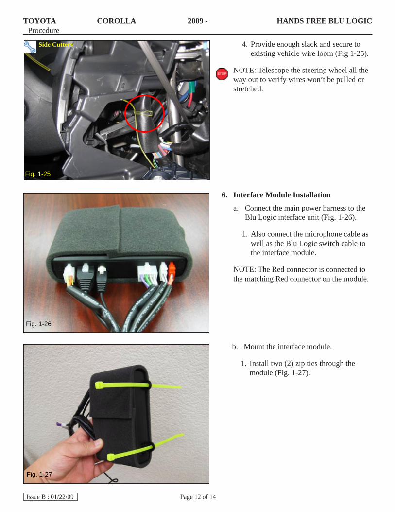
Fig. 1-25
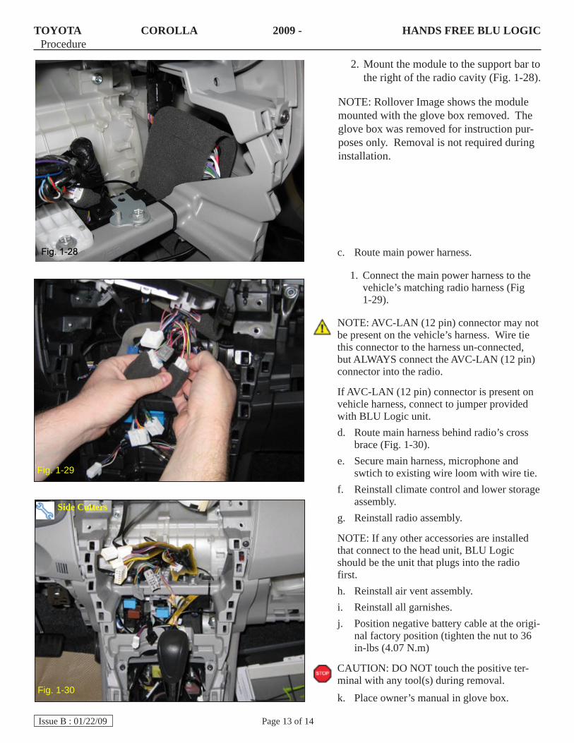
Interface Module Installation6.
Connect the main power harness to the a. Blu Logic interface unit (Fig. 1-26).
Also connect the microphone cable as 1. well as the Blu Logic switch cable to the interface module.
NOTE: The Red connector is connected to the matching Red connector on the module.
Provide enough slack and secure to 4. existing vehicle wire loom (Fig 1-25).
NOTE: Telescope the steering wheel all the way out to verify wires won’t be pulled or stretched.
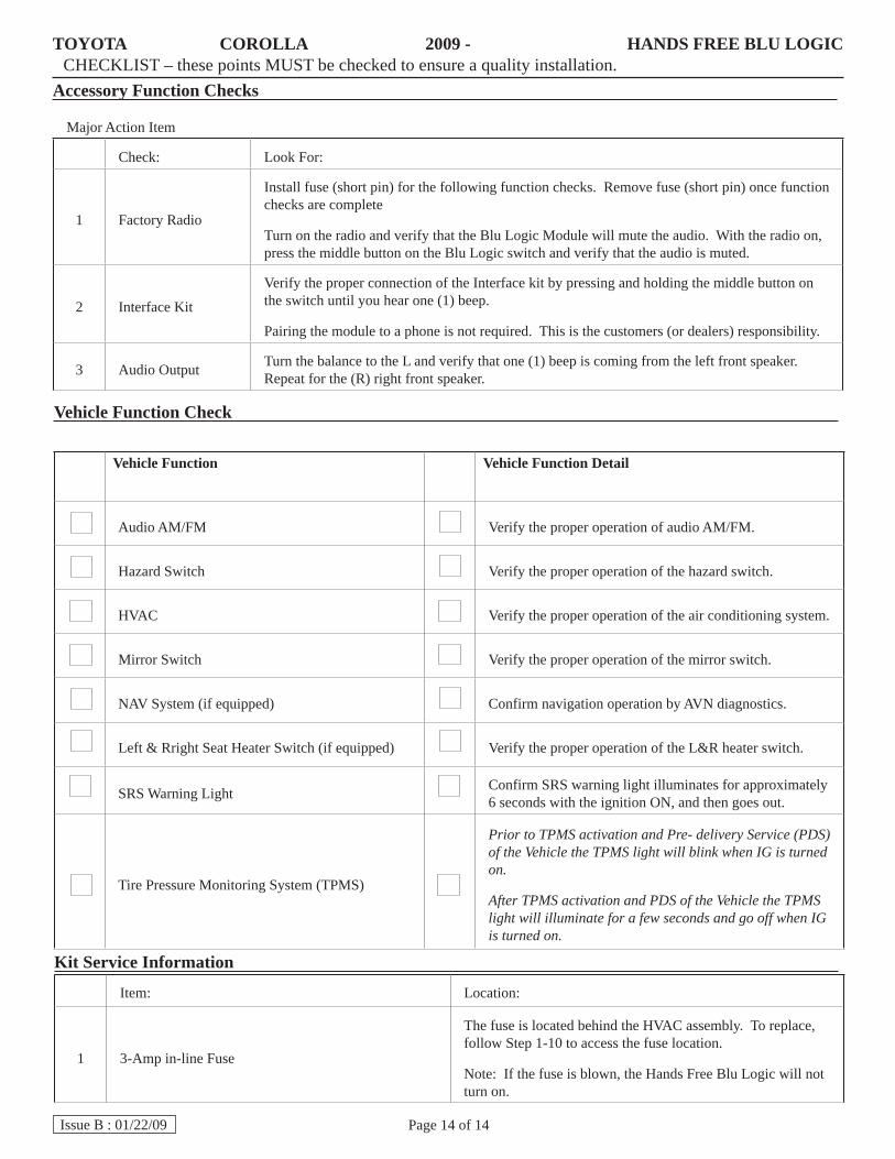
Mount the interface module.b.
Install two (2) zip ties through the 1. module (Fig. 1-27).
Side Cutters
Fig. 1-26
Fig. 1-27
TOYOTA COROLLA 2009 - HANDS FREE BLU LOGICProcedure
Page 13 of 14Issue B : 01/22/09
Mount the module to the support bar to 2. the right of the radio cavity (Fig. 1-28).
NOTE: Rollover Image shows the module mounted with the glove box removed. The glove box was removed for instruction pur-poses only. Removal is not required during installation.
Route main power harness.c.
Connect the main power harness to the 1. vehicle’s matching radio harness (Fig 1-29).
NOTE: AVC-LAN (12 pin) connector may not be present on the vehicle’s harness. Wire tie this connector to the harness un-connected, but ALWAYS connect the AVC-LAN (12 pin) connector into the radio.
If AVC-LAN (12 pin) connector is present on vehicle harness, connect to jumper provided with BLU Logic unit.
Route main harness behind radio’s cross d. brace (Fig. 1-30).Secure main harness, microphone and e. swtich to existing wire loom with wire tie.Reinstall climate control and lower storage f. assembly.Reinstall radio assembly.g.
NOTE: If any other accessories are installed that connect to the head unit, BLU Logic should be the unit that plugs into the radio first.
Reinstall air vent assembly.h. Reinstall all garnishes.i. Position negative battery cable at the origi-j. nal factory position (tighten the nut to 36 in-lbs (4.07 N.m)
CAUTION: DO NOT touch the positive ter-minal with any tool(s) during removal.
Place owner’s manual in glove box.k.
Fig. 1-29
Fig. 1-30
Side Cutters
TOYOTA COROLLA 2009 - HANDS FREE BLU LOGICCHECKLIST – these points MUST be checked to ensure a quality installation.
Page 14 of 14Issue B : 01/22/09
Accessory Function Checks
Major Action Item
Check: Look For:
1 Factory Radio
Install fuse (short pin) for the following function checks. Remove fuse (short pin) once function checks are complete
Turn on the radio and verify that the Blu Logic Module will mute the audio. With the radio on, press the middle button on the Blu Logic switch and verify that the audio is muted.
2 Interface Kit
Verify the proper connection of the Interface kit by pressing and holding the middle button on the switch until you hear one (1) beep.
Pairing the module to a phone is not required. This is the customers (or dealers) responsibility.
3 Audio Output Turn the balance to the L and verify that one (1) beep is coming from the left front speaker. Repeat for the (R) right front speaker.
Kit Service Information
Item: Location:
1 3-Amp in-line Fuse
The fuse is located behind the HVAC assembly. To replace, follow Step 1-10 to access the fuse location.
Note: If the fuse is blown, the Hands Free Blu Logic will not turn on.
Vehicle Function Check
Vehicle Function Vehicle Function Detail
Audio AM/FM Verify the proper operation of audio AM/FM.
Hazard Switch Verify the proper operation of the hazard switch.
HVAC Verify the proper operation of the air conditioning system.
Mirror Switch Verify the proper operation of the mirror switch.
NAV System (if equipped) Confirm navigation operation by AVN diagnostics.
Left & Rright Seat Heater Switch (if equipped) Verify the proper operation of the L&R heater switch.
SRS Warning Light Confirm SRS warning light illuminates for approximately 6 seconds with the ignition ON, and then goes out.
Tire Pressure Monitoring System (TPMS)
Prior to TPMS activation and Pre- delivery Service (PDS) of the Vehicle the TPMS light will blink when IG is turned on.
After TPMS activation and PDS of the Vehicle the TPMS light will illuminate for a few seconds and go off when IG is turned on.