Embed Size (px)
Citation preview

TP48200A-D17B6 V300R001
User Manual
Issue 01
Date 2012-07-13
HUAWEI TECHNOLOGIES CO., LTD.

Issue 01 (2012-07-13) Huawei Proprietary and Confidential
Copyright © Huawei Technologies Co., Ltd
i
Copyright © Huawei Technologies Co., Ltd. 2012. All rights reserved.
No part of this document may be reproduced or transmitted in any form or by any means without prior
written consent of Huawei Technologies Co., Ltd.
Trademarks and Permissions
and other Huawei trademarks are trademarks of Huawei Technologies Co., Ltd.
All other trademarks and trade names mentioned in this document are the property of their respective
holders.
Notice
The purchased products, services and features are stipulated by the contract made between Huawei and
the customer. All or part of the products, services and features described in this document may not be
within the purchase scope or the usage scope. Unless otherwise specified in the contract, all statements,
information, and recommendations in this document are provided "AS IS" without warranties, guarantees or
representations of any kind, either express or implied.
The information in this document is subject to change without notice. Every effort has been made in the
preparation of this document to ensure accuracy of the contents, but all statements, information, and
recommendations in this document do not constitute a warranty of any kind, express or implied.
Huawei Technologies Co., Ltd.
Address: Huawei Industrial Base
Bantian, Longgang
Shenzhen 518129
People's Republic of China
Website: http://www.huawei.com
Email: [email protected]
TP48200A-D17B6
User Manual About This Document
Issue 01 (2012-07-13) Huawei Proprietary and Confidential
Copyright © Huawei Technologies Co., Ltd
ii
About This Document
Purpose
This document describes the TP48200A-D17B6 in terms of its features, structure, components,
installation, commissioning, and maintenance.
Intended Audience
This document is intended for:
Sales engineers
Technical support personnel
Maintenance personnel
Symbol Conventions
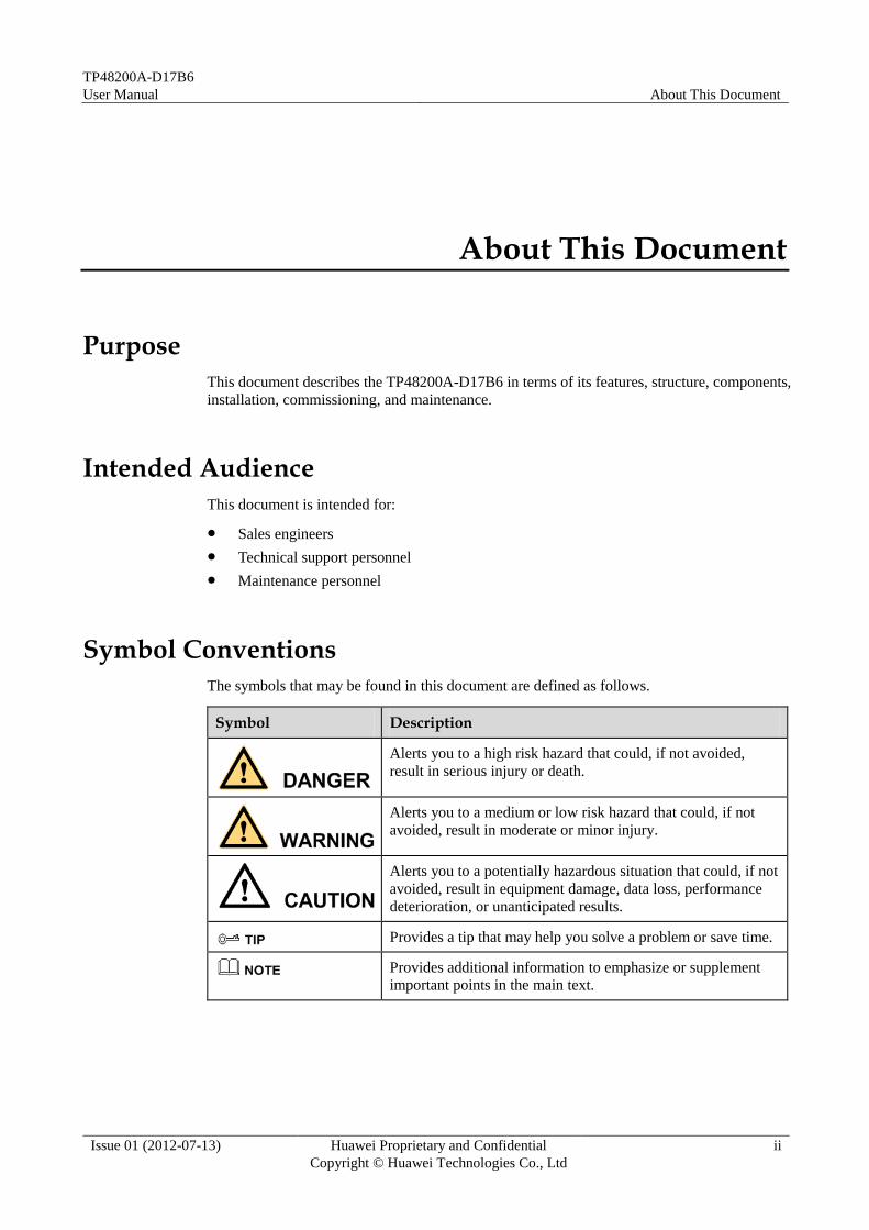
The symbols that may be found in this document are defined as follows.
Symbol Description
Alerts you to a high risk hazard that could, if not avoided,
result in serious injury or death.
Alerts you to a medium or low risk hazard that could, if not
avoided, result in moderate or minor injury.
Alerts you to a potentially hazardous situation that could, if not
avoided, result in equipment damage, data loss, performance
deterioration, or unanticipated results.
Provides a tip that may help you solve a problem or save time.
Provides additional information to emphasize or supplement
important points in the main text.

TP48200A-D17B6
User Manual About This Document
Issue 01 (2012-07-13) Huawei Proprietary and Confidential
Copyright © Huawei Technologies Co., Ltd
iii
Change History
Changes between document issues are cumulative. The latest document issue contains all the
changes made in earlier issues.
Issue 01 (2012-07-13)
This issue is the first official release.

TP48200A-D17B6
User Manual Contents
Issue 01 (2012-07-13) Huawei Proprietary and Confidential
Copyright © Huawei Technologies Co., Ltd
iv
Contents
About This Document .................................................................................................................... ii
1 Overview ......................................................................................................................................... 1
1.1 Designation Explanation .................................................................................................................................. 1
1.2 Typical Networking .......................................................................................................................................... 1
1.3 Features ............................................................................................................................................................ 2
1.4 Configuration ................................................................................................................................................... 3
1.5 Working Principles ........................................................................................................................................... 6
2 Component Description ............................................................................................................... 7
2.1 Cabinet ............................................................................................................................................................. 7
2.2 Temperature Control Unit ................................................................................................................................ 8
2.2.1 Overview ................................................................................................................................................. 8
2.2.2 Heater ...................................................................................................................................................... 9
2.2.3 Fan Assembly ........................................................................................................................................ 11
2.3 Rectifier .......................................................................................................................................................... 12
2.3.1 Appearance ............................................................................................................................................ 12
2.3.2 Panel...................................................................................................................................................... 12
2.4 PDU ................................................................................................................................................................ 14
2.4.1 DC PDU ................................................................................................................................................ 14
2.4.2 AC PDU ................................................................................................................................................ 15
2.5 Storage Battery ............................................................................................................................................... 15
2.6 Lamp .............................................................................................................................................................. 17
2.7 Monitoring Unit ............................................................................................................................................. 18
2.7.1 SMU02B ............................................................................................................................................... 18
2.7.2 UIM02D ................................................................................................................................................ 20
2.7.3 LCD User Interface ............................................................................................................................... 26
2.7.4 Web User Interface ................................................................................................................................ 32
3 Safety Precautions ....................................................................................................................... 42
3.1 Overview ........................................................................................................................................................ 42
3.2 Local Safety Regulations ............................................................................................................................... 42
3.3 Grounding Requirements ............................................................................................................................... 42
3.4 Human Safety ................................................................................................................................................. 43
3.5 Equipment Safety ........................................................................................................................................... 43

TP48200A-D17B6
User Manual Contents
Issue 01 (2012-07-13) Huawei Proprietary and Confidential
Copyright © Huawei Technologies Co., Ltd
v
3.6 Electrical Safety ............................................................................................................................................. 43
4 Installation and Commissioning.............................................................................................. 46
5 Maintenance ................................................................................................................................. 47
5.1 Routine Maintenance...................................................................................................................................... 47
5.2 Troubleshooting .............................................................................................................................................. 50
5.3 Component Replacment ................................................................................................................................. 58
A Technical Specifications ........................................................................................................... 67
B Acronyms and Abbreviations .................................................................................................. 70

TP48200A-D17B6
User Manual 1 Overview
Issue 01 (2012-07-13) Huawei Proprietary and Confidential
Copyright © Huawei Technologies Co., Ltd
1
1 Overview
1.1 Designation Explanation
The TP48200A-D17B6 is an integrated outdoor backup alternating current-to-direct current
(AC-to-DC) power system that employs 48 V, 50 A rectifiers and outputs a maximum of 200
A current.
Figure 1-1 shows the definition of the product name TP48200A-D17B6.
Figure 1-1 Definition of each part in the product name
The TP48200A-D17B6 is used in Class B environments.
The class-B environment refers to rooms in which the humidity and temperature are uncontrollable,
the general outdoor environment including simple sun-shading environment (such as canopy), and
the environment where humidity reaches 100% occasionally.
1.2 Typical Networking
The TP48200A-D17B6, AC power supply, automatic transfer switch (ATS), alternating
current distribution box (ACDB), storage batteries, and related devices constitute a site power
solution. Figure 1-2 shows the positioning of the TP48200A-D17B6 in the typical site power
solution.

TP48200A-D17B6
User Manual 1 Overview
Issue 01 (2012-07-13) Huawei Proprietary and Confidential
Copyright © Huawei Technologies Co., Ltd
2
Figure 1-2 TP48200A-D17B6 in the typical site power solution
1.3 Features
The TP48200A-D17B6 supplies stable power to 48 V DC equipment and provides a
maximum current of 200 A.
Easy Installation
The monitoring unit and rectifier are hot-swappable. This facilitates the system installation,
saves maintenance time, and reduces the operational expenditure (OPEX).
Intelligent Hibernation
To improve efficiency, the TP48200A-D17B6 can put one or more rectifiers in hibernation
based on the actual power usage.
High Efficiency
The TP48200A-D17B6 uses rectifiers with a 96% efficiency record.
Low Imbalance Degree of Current Equalization
The imbalance degree of current equalization for rectifiers is less than 5%.
Remote Monitoring
OPEX is reduced when the TP48200A-D17B6 performs comprehensive power management
and battery management functions by connecting to the element management system (EMS).
Wide Range of AC Input Voltage
The AC input voltage of the TP48200A-D17B6 ranges from 346 V AC ~ 415 V AC / 200 V
AC ~ 240 V AC.

TP48200A-D17B6
User Manual 1 Overview
Issue 01 (2012-07-13) Huawei Proprietary and Confidential
Copyright © Huawei Technologies Co., Ltd
3
Safety and Regulation Compliance The TP48200A-D17B6 complies with Conformite Europeenne (CE) standards, Technical
Watch-Over Association (TUV) standards.
The power distribution components and the monitoring unit comply with CE standards
and TUV standards.
The rectifier complies with underwriters laboratory (UL), CE, and TUV standards.
Low Noise
The sound power is less than 61 dB(A)@25 ºC and less than 67 dB(A)@45 ºC, and the noise
specifications comply with ETS 300 753 Class 4.1E (rural environment).
High Protection Level
The cabinet protection level is IP55.
Periodic Battery Test
The periodic battery test is used to test battery health. The test allows storage batteries to be
fully charged automatically and then to discharge till the voltage reaches the value of Test End Volt. The test is performed periodically (every 90 days by default).
1.4 Configuration
The TP48200A-D17B6 is a cabinet that houses the fans, rectifiers, monitoring unit, power
distribution unit (PDU), heater, lamp and sensors etc.
Table 1-1 TP48200A-D17B6 Configuration
Item Specifications
Rectifiers (R4850G1) Standard configuration: 3 PCS
Optional configuration: 2 to 4 PCS
Monitoring unit
(SMU02B & UIM02D)
1 PCS
AC input mode Single-phase three-line (L, N, PE)
Three-phase five-line (L1, L2, L3, N, PE)
AC PDU 4 x 25 A/1P MCB, 1 x 63A/4P MCB
16 A European-standard maintenance socket and 10 A
electronic leakage circuit breaker that trips automatically if
the leakage current is 30 mA or greater.
DC PDU Battery low voltage disconnection(BLVD): 2 x 10A/1P
MCB, 6 x 16A/1P MCB, 1 x 10A/1P MCB for lamp
Load low voltage disconnection(LLVD): 4 x 10A/1P MCB,
3 x 16A/1P MCB, 3 x 25A/1P MCB, 1 x 100A/1P MCB
Battery branch: 2 x 125A/1P MCB

TP48200A-D17B6
User Manual 1 Overview
Issue 01 (2012-07-13) Huawei Proprietary and Confidential
Copyright © Huawei Technologies Co., Ltd
4
Item Specifications
Heater (HAU03A-01) 1 PCS
Lamp 1 PCS
Sensors Door status sensor: 1 PCS
Smoke sensor: 1 PCS
Battery temperature sensor: 1 PCS
Environment temperature sensor: 2 PCS

TP48200A-D17B6
User Manual 1 Overview
Issue 01 (2012-07-13) Huawei Proprietary and Confidential
Copyright © Huawei Technologies Co., Ltd
5
Figure 1-3 TP48200A-D17B6 interior
(1) Fan assembly (2) Monitoring unit (3) Space for rectifiers
(4) Alternating current power
distribution unit(AC PDU)
(5) Direct current power
distribution unit(DC PDU)
(6) Space for customer equipments
(7) Heater (8) Battery rack (9) Base
(10) Terminal block (11) Lamp (12) Door lock
(13) Air filter

TP48200A-D17B6
User Manual 1 Overview
Issue 01 (2012-07-13) Huawei Proprietary and Confidential
Copyright © Huawei Technologies Co., Ltd
6
1.5 Working Principles
Working principles are described as follows:
The rectifier converts AC power into –48 V DC power.
The direct currents (DCs) generated by rectifiers converge on a busbar and then divide
into multiple routes.
The monitoring unit monitors operating parameters in real time, analyzes the operating
status, and generates alarms when necessary.
Figure 1-4 Conceptual diagram of TP48200A-D17B6
TP48200A-D17B6
User Manual 2 Component Description
Issue 01 (2012-07-13) Huawei Proprietary and Confidential
Copyright © Huawei Technologies Co., Ltd
7
2 Component Description
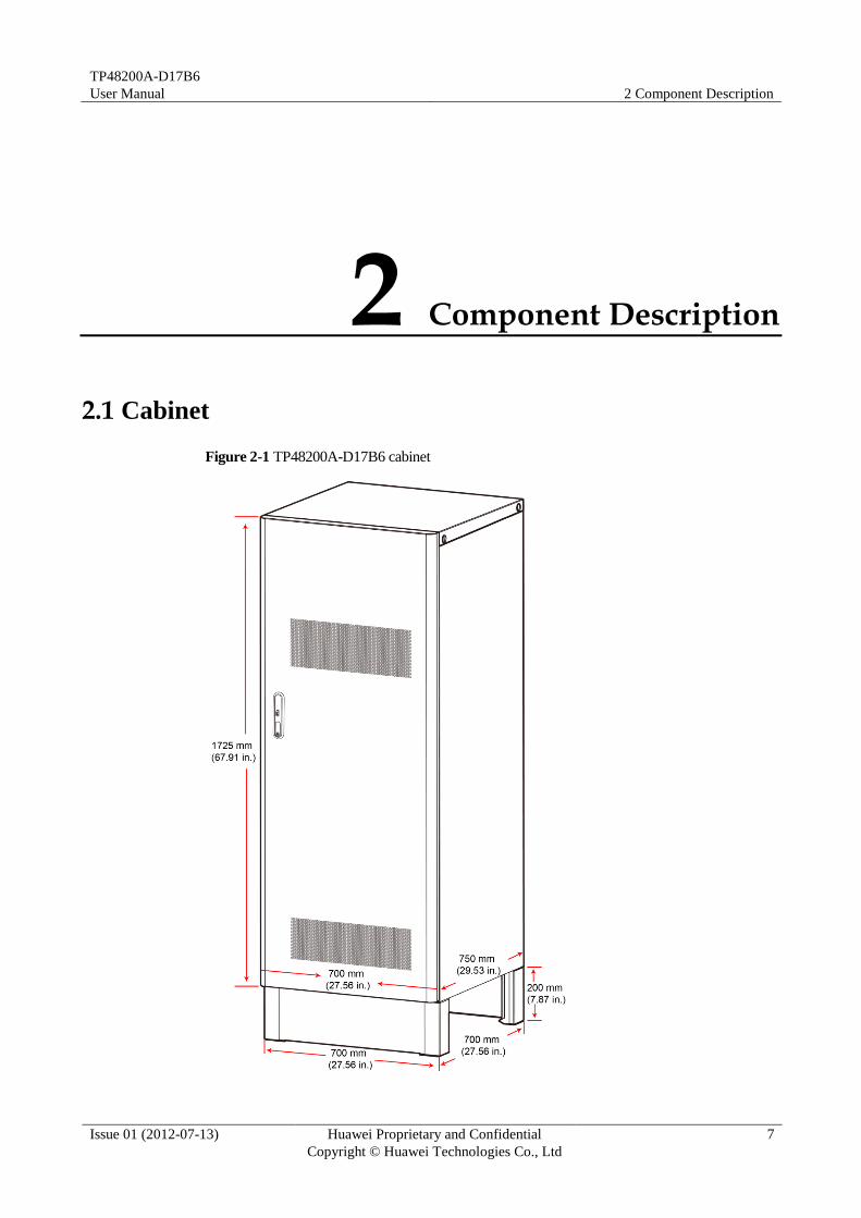
2.1 Cabinet
Figure 2-1 TP48200A-D17B6 cabinet

TP48200A-D17B6
User Manual 2 Component Description
Issue 01 (2012-07-13) Huawei Proprietary and Confidential
Copyright © Huawei Technologies Co., Ltd
8
Table 2-1 Structures
Item Specifications
Dimensions (H x W x D)
of the cabinet
1725 mm x 700 mm x 750 mm (67.91 in. x 27.56 in. x 29.53
in.)
Dimensions (H x W x D)
of the base
200 mm x 700 mm x 700 mm (7.87 in. x 27.56 in. x 27.56
in.)
Weight <150 kg (without rectifiers and storage batteries)
Space for customer 17 U (755.6 mm [29.75 in.]) for customer equipment and
8 U (355.6 mm [14.00 in.]) for one-layer batteries
9 U (400.1 mm [15.75 in.]) for customer equipment and
16 U (711.2 mm [28.00 in.]) for two-layer batteries
Protection level IP55
Installation Ground installation
Maintenance Operated and maintained from the front
Materials Double-shell aluminum
2.2 Temperature Control Unit
2.2.1 Overview
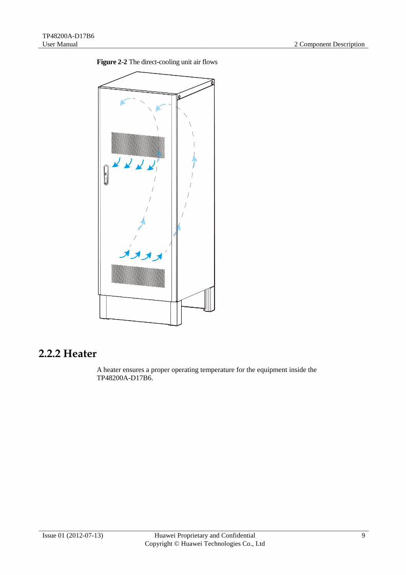
The temperature control unit of the TP48200A-D17B6 is composed of a direct-cooling unit
and a heater. The direct-cooling unit accelerates the air ventilation and adjusts the temperature
inside the cabinet by using an air-exhaust device, an air-intake device, an air filter, and a fan
assembly. The heater keeps the internal cabinet at an optimal operating temperature.
The direct-cooling unit and heater do not work simultaneously.
The TP48200A-D17B6 with a direct-cooling unit adjusts the fan speed based on the ambient
temperature and the temperature inside the cabinet. If the ambient temperature is far below the
temperature inside the cabinet or the temperature inside the cabinet is lower than the
minimum value, the TP48200A-D17B6 stops the fan. This function saves energy because the
TP48200A-D17B6 is cooled by external air.
Air flows
The direct-cooling unit direct air into the cabinet through the lower part of the door and out of
the cabinet through the upper.
TP48200A-D17B6
User Manual 2 Component Description
Issue 01 (2012-07-13) Huawei Proprietary and Confidential
Copyright © Huawei Technologies Co., Ltd
9
Figure 2-2 The direct-cooling unit air flows
2.2.2 Heater
A heater ensures a proper operating temperature for the equipment inside the
TP48200A-D17B6.

TP48200A-D17B6
User Manual 2 Component Description
Issue 01 (2012-07-13) Huawei Proprietary and Confidential
Copyright © Huawei Technologies Co., Ltd
10
Panel
Figure 2-3 HAU03A-01
(1) Alternating current (AC) input port (2) Indicator (3) Alarm port
(4) Control port
Table 2-2 describes the indicators on the heater panel.
Table 2-2 Indicator description
Silk Screen
Color Status Meaning
RUN Green Steady on The heater is powered on and takes a self-test.
Off The heater is not powered on.
ALM Red Off No alarm is generated.
Steady on An alarm is generated and the heater needs to be
replaced.
Specifications
Table 2-3 lists the heater technical specifications.
Table 2-3 Heater technical specifications
Item Specifications
Operating voltage 100-240 V AC
Voltage frequency 45–65 Hz
Operating temperature –40°C to +65°C
Heater startup
temperature
The heater starts when the temperature is below or equal to 0°C.
The value range is -10°C to 0°C.
Heater stop
temperature
The heater stops when the temperature is above or equal to 5°C.
The value range is 5°C to 15°C.
Heating power 500 W
TP48200A-D17B6
User Manual 2 Component Description
Issue 01 (2012-07-13) Huawei Proprietary and Confidential
Copyright © Huawei Technologies Co., Ltd
11
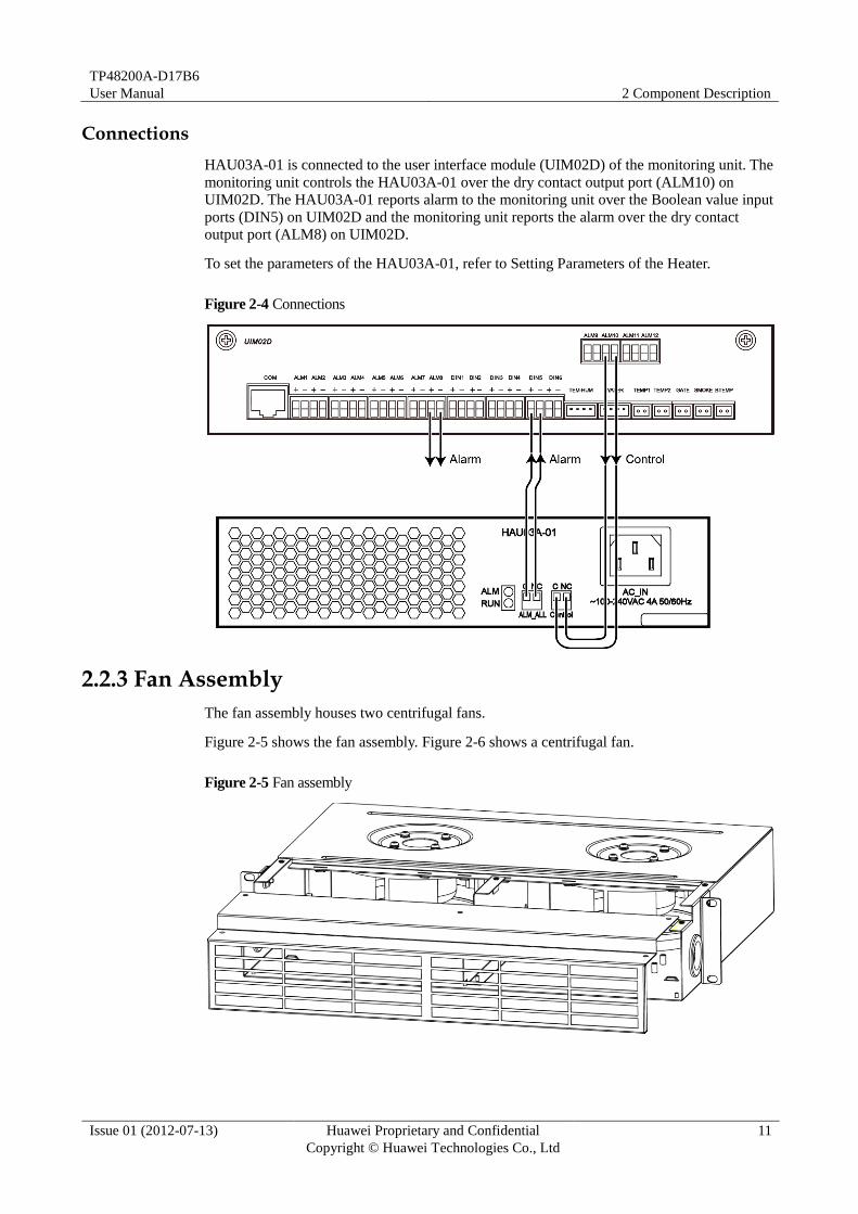
Connections
HAU03A-01 is connected to the user interface module (UIM02D) of the monitoring unit. The
monitoring unit controls the HAU03A-01 over the dry contact output port (ALM10) on
UIM02D. The HAU03A-01 reports alarm to the monitoring unit over the Boolean value input
ports (DIN5) on UIM02D and the monitoring unit reports the alarm over the dry contact
output port (ALM8) on UIM02D.
To set the parameters of the HAU03A-01, refer to Setting Parameters of the Heater.
Figure 2-4 Connections
2.2.3 Fan Assembly
The fan assembly houses two centrifugal fans.
Figure 2-5 shows the fan assembly. Figure 2-6 shows a centrifugal fan.
Figure 2-5 Fan assembly

TP48200A-D17B6
User Manual 2 Component Description
Issue 01 (2012-07-13) Huawei Proprietary and Confidential
Copyright © Huawei Technologies Co., Ltd
12
Figure 2-6 Centrifugal fan
Table 2-4 Technical specifications of fan assembly
Item Specifications
Rated voltage –48 V DC
Rated power 2 x 34 W
Rotational speed 3100 rpm
Ventilation quantity of single fan 565m3/h
Ventilation quantity of the fan assembly 1090m3/h
Maximum heat dissipation of the power
system 220W/K; 1760W with ⊿T = 8°C @ two
fans in operation with 100% speed)
2.3 Rectifier
2.3.1 Appearance
The rectifier converts the AC input power into stable 48 V DC power. The TP48200A-D17B6
can be configured with two, three, or four rectifiers.
Figure 2-7 shows the rectifier.
Figure 2-7 Rectifier
2.3.2 Panel
The rectifier panel provides the run indicator, alarm indicator, and fault indicator. Figure 2-8
shows the rectifier panel.

TP48200A-D17B6
User Manual 2 Component Description
Issue 01 (2012-07-13) Huawei Proprietary and Confidential
Copyright © Huawei Technologies Co., Ltd
13
Figure 2-8 Rectifier panel
(1) Run indicator (2) Alarm indicator (3) Fault indicator
Table 2-5 Indicator description of rectifier
Indicator Color Status Description Measures
Run
indicator
Green Steady on The rectifier output is
normal.
The rectifier runs
properly, and no
measure is required.
Off The rectifier has no output. Replace the rectifier if
the AC input is normal.
Alarm
indicator
Yellow Off No alarm is generated. No measure is required.
Steady on The rectifier generates a
prewarning for power
limiting due to
overtemperature.
Check that the air vent is
not blocked and the
ambient temperature is
within a normal range.
The rectifier generates an
alarm for shutdown due to
ambient overtemperature
protection.
The rectifier generates an
alarm due to AC input
overvoltage or undervoltage
protection.
Check that the electrical
grid voltage is within a
normal range.
The rectifier is hibernated. No measure is required.
Fault
indicator
Red Off The rectifier is not faulty. No measure is required.
Steady on The rectifier is locked due to
output overvoltage.
Pull out the rectifier and
reinsert it after one
minute.
There is no output
because the rectifier is faulty.
Replace the rectifier.

TP48200A-D17B6
User Manual 2 Component Description
Issue 01 (2012-07-13) Huawei Proprietary and Confidential
Copyright © Huawei Technologies Co., Ltd
14
Indicator Color Status Description Measures
Blinking
at 4 Hz
The rectifier is loading an
application program.
The rectifier
automatically recovers
after loading, and no
measure is required.
2.4 PDU
PDUs are classified into the DC PDU and AC PDU.
2.4.1 DC PDU
Figure 2-9 shows the DC PDU.
Figure 2-9 DC PDU
Table 2-6 Circuit breaker distribution
Category Silkscreen Specification
Battery low voltage
disconnection(BLVD)
LAMP 10 A
F1 10 A
F2 10 A
F3 16 A
F4 16 A
F5 16 A
F6 16 A
F7 16 A
F8 16 A
Load low voltage
disconnection(LLVD)
F9 10 A
F10 10 A
F11 10 A
F12 10 A
F13 16 A
F14 16 A

TP48200A-D17B6
User Manual 2 Component Description
Issue 01 (2012-07-13) Huawei Proprietary and Confidential
Copyright © Huawei Technologies Co., Ltd
15
Category Silkscreen Specification
F15 16 A
F16 25A
F17 25A
F18 25A
F19 100A
Battery branch BAT1 125 A
BAT2 125 A
2.4.2 AC PDU
Figure 2-10 shows the AC PDU.
Figure 2-10 AC PDU
Table 2-7 Circuit breaker distribution
Silkscreen Specification
PSU Four 25 A/1P circuit breaker
AC INPUT One 63A/4P circuit breaker
HEATER One 10 A/1P circuit breaker
SOCKET 16 A European-standard maintenance socket and 10 A
electronic leakage circuit breaker that trips automatically if
the leakage current is 30 mA or greater.
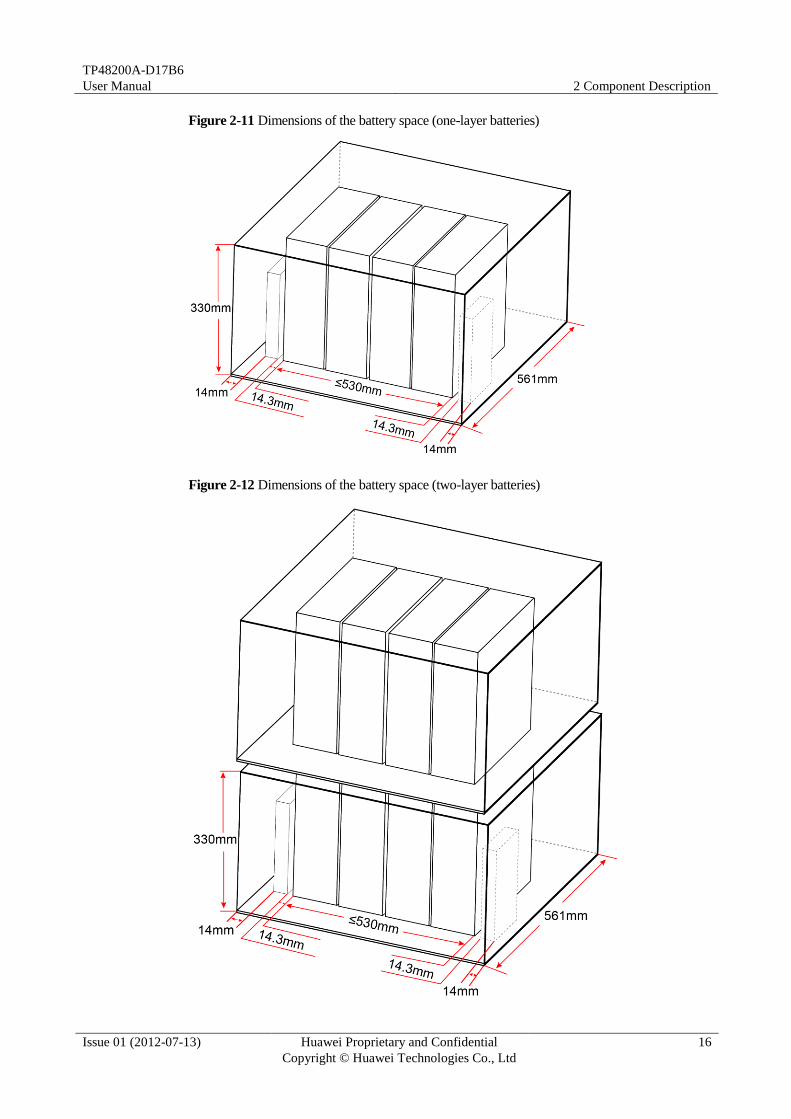
2.5 Storage Battery
The TP48200A-D17B6 can be configured with one or two layers (12V/150 Ah monobloc)
batteries for power backup. The dimensions of the battery space refer to Figure 2-11 and
Figure 2-12.
TP48200A-D17B6
User Manual 2 Component Description
Issue 01 (2012-07-13) Huawei Proprietary and Confidential
Copyright © Huawei Technologies Co., Ltd
16
Figure 2-11 Dimensions of the battery space (one-layer batteries)
Figure 2-12 Dimensions of the battery space (two-layer batteries)

TP48200A-D17B6
User Manual 2 Component Description
Issue 01 (2012-07-13) Huawei Proprietary and Confidential
Copyright © Huawei Technologies Co., Ltd
17
Storage batteries are prepared by customer.
2.6 Lamp
Appearance
Figure 2-13 shows the lamp.
Figure 2-13 Lamp
Technical Specifications
Table 2-8 lists the technical specifications of the lamp.
Table 2-8 Technical specifications of the lamp
Item Specifications
Rated voltage 48 V DC
Rated power ≤ 1 W
Luminance 300 cd/m2
Color of the emitted light White
Certificate UL
NOTE

TP48200A-D17B6
User Manual 2 Component Description
Issue 01 (2012-07-13) Huawei Proprietary and Confidential
Copyright © Huawei Technologies Co., Ltd
18
2.7 Monitoring Unit
2.7.1 SMU02B
Panel
Figure 2-14 shows the SMU02B panel.
Figure 2-14 Panel
(1) Running status indicator (2) Minor alarm indicator (3)Major alarm indicator
(4) Liquid crystal display
(LCD)
(5) Locking latch (6) Four buttons
(7)USB (Reserved) (8) RS485/RS232 (9) FE
Indicators
Table 2-9 describes the SMU02B indicators.
Table 2-9 Indicator description
Indicator Color Status Description
Running
status
Green Off The SMU02B is faulty or has no DC input.
Blinking at
0.5 Hz
The SMU02B runs properly and
communicates with the host properly.
Blinking at 4
Hz
The SMU02B runs properly but does not
communicate with the host properly.
TP48200A-D17B6
User Manual 2 Component Description
Issue 01 (2012-07-13) Huawei Proprietary and Confidential
Copyright © Huawei Technologies Co., Ltd
19
Indicator Color Status Description
Minor alarm
indicator
Yellow Off No minor and warning alarm.
Steady on A minor or warning alarm is generated.
Major alarm
indicator
Red Off No critical and major alarm.
Steady on A critical or major alarm is generated.
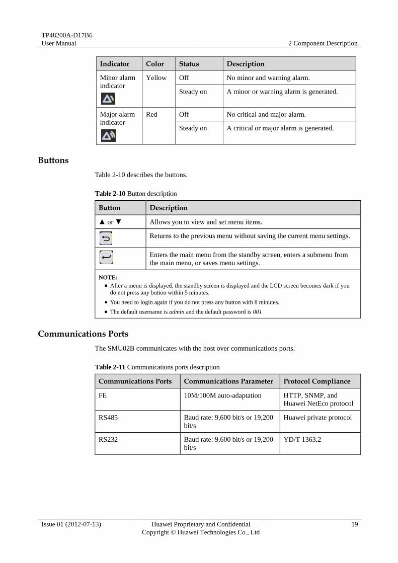
Buttons
Table 2-10 describes the buttons.
Table 2-10 Button description
Button Description
▲ or ▼ Allows you to view and set menu items.
Returns to the previous menu without saving the current menu settings.
Enters the main menu from the standby screen, enters a submenu from
the main menu, or saves menu settings.
NOTE:
After a menu is displayed, the standby screen is displayed and the LCD screen becomes dark if you
do not press any button within 5 minutes.
You need to login again if you do not press any button with 8 minutes.
The default username is admin and the default password is 001
Communications Ports
The SMU02B communicates with the host over communications ports.
Table 2-11 Communications ports description
Communications Ports Communications Parameter Protocol Compliance
FE 10M/100M auto-adaptation HTTP, SNMP, and
Huawei NetEco protocol
RS485 Baud rate: 9,600 bit/s or 19,200
bit/s
Huawei private protocol
RS232 Baud rate: 9,600 bit/s or 19,200
bit/s
YD/T 1363.2

TP48200A-D17B6
User Manual 2 Component Description
Issue 01 (2012-07-13) Huawei Proprietary and Confidential
Copyright © Huawei Technologies Co., Ltd
20
Figure 2-15 FE and RS485/RS232 pin definition
Table 2-12 FE pin definition
Pin Signal Description
1 TX+ FE transmit
2 TX-
3 RX+ FE receive
6 RX-
Table 2-13 RS485/RS232 pin definition
Pin Signal Description
1 TX+ RS485 transmit
2 TX-
4 RX+ RS485 receive
5 RX-
3 RX232 RS232 receive
7 TX232 RS232 transmit
6 PGND Ground
8 - -
2.7.2 UIM02D
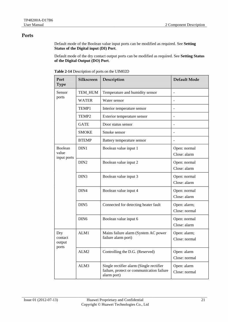
UIM02D supports 12 dry contact output ports, 6 Boolean value input ports and 7 sensor ports.
Panel
Figure 2-16 Appearance UIM02D Panel
TP48200A-D17B6
User Manual 2 Component Description
Issue 01 (2012-07-13) Huawei Proprietary and Confidential
Copyright © Huawei Technologies Co., Ltd
21
Ports
Default mode of the Boolean value input ports can be modified as required. See Setting
Status of the Digital input (DI) Port.
Default mode of the dry contact output ports can be modified as required. See Setting Status
of the Digital Output (DO) Port.
Table 2-14 Description of ports on the UIM02D
Port Type
Silkscreen Description Default Mode
Sensor
ports
TEM_HUM Temperature and humidity sensor -
WATER Water sensor -
TEMP1 Interior temperature sensor -
TEMP2 Exterior temperature sensor -
GATE Door status sensor -
SMOKE Smoke sensor -
BTEMP Battery temperature sensor -
Boolean
value
input ports
DIN1 Boolean value input 1
Open: normal
Close: alarm
DIN2 Boolean value input 2 Open: normal
Close: alarm
DIN3 Boolean value input 3 Open: normal
Close: alarm
DIN4 Boolean value input 4 Open: normal
Close: alarm
DIN5 Connected for detecting heater fault Open: alarm;
Close: normal
DIN6 Boolean value input 6 Open: normal
Close: alarm
Dry
contact
output
ports
ALM1 Mains failure alarm (System AC power
failure alarm port)
Open: alarm;
Close: normal
ALM2 Controlling the D.G. (Reserved) Open: alarm
Close: normal
ALM3 Single rectifier alarm (Single rectifier
failure, protect or communication failure
alarm port)
Open: alarm
Close: normal

TP48200A-D17B6
User Manual 2 Component Description
Issue 01 (2012-07-13) Huawei Proprietary and Confidential
Copyright © Huawei Technologies Co., Ltd
22
Port Type
Silkscreen Description Default Mode
ALM4 SPD fault alarm (AC or DC surge
protector failure alarm port)
Open: alarm
Close: normal
ALM5 Fuse disconnection alarm (Battery or
load fuse disconnection alarm port)
Open: alarm
Close: normal
ALM6 Temperature alarm (Battery or cabinet
ambient temperature too high or low
alarm port)
Open: alarm
Close: normal
ALM7 Door open alarm (Cabinet door open
alarm port)
Open: alarm
Close: normal
ALM8 Temperature control alarm (Heater or
fans failure alarm port)
Open: alarm
Close: normal
ALM9 Multi rectifiers alarm (Two or more
rectifiers failure alarm port)
Open: alarm
Close: normal
ALM10 Connected for controlling the heater Open: the heater
working according
to the temperature.
Close: power off the
heater
ALM11 Reserved Open: alarm
Close: normal
ALM12 Connected for controlling the lamp Open: close the
lamp
Close: open the
lamp
COM Port COM RS485 -

TP48200A-D17B6
User Manual 2 Component Description
Issue 01 (2012-07-13) Huawei Proprietary and Confidential
Copyright © Huawei Technologies Co., Ltd
23
Pin Definition
Figure 2-17 Pins of sensor ports
Table 2-15 Pin Definition
Silk Screen Pin Pin definition
WATER 1 12V
2 WATER
3 GND
4 -
TEMHUM 1 12V
2 ENV_TEMP
3 12V
4 ENV_HUM
TEMP1 1 TEMP1
2 GND
TEMP2 1 TEMP2
2 GND
GATE 1 DIN7+
2 JTD7
SMOKE 1 12V
2 SMOKE
BTEMP 1 Btemp1
2 GND

TP48200A-D17B6
User Manual 2 Component Description
Issue 01 (2012-07-13) Huawei Proprietary and Confidential
Copyright © Huawei Technologies Co., Ltd
24
Terminal block
Terminal block is in the right side of the cabinet. Two RJ45 cables are used for connecting dry
contacts and the host.

TP48200A-D17B6
User Manual 2 Component Description
Issue 01 (2012-07-13) Huawei Proprietary and Confidential
Copyright © Huawei Technologies Co., Ltd
25
Figure 2-18 Terminal block

TP48200A-D17B6
User Manual 2 Component Description
Issue 01 (2012-07-13) Huawei Proprietary and Confidential
Copyright © Huawei Technologies Co., Ltd
26
2.7.3 LCD User Interface
Symbol Conventions
Symbol Description
Press one time Enter button.
Press one time Down button.
Press one time Cancel button.
Press one time Up button.
Press more than one times Down button.
Press one time Enter button and more than one times Down button.
Picture with black border shows the path or view parameter
Picture with red border shows the variable parameter
Selecting a Display Language
After the SMU is powered on, the screen for selecting a display language is displayed. You
can select Chinese, English or other language by pressing ▲ or ▼ and enter the standby
screen by pressing Enter.
Figure 2-19 Selecting Language
Querying Active Alarms
This section describes how to query active alarms on the LCD, as shown in Figure 2-20. The
parameter values in Figure 2-20 are for reference only.
Enter
Down
Cancel
Up
Down
Enter Down
TP48200A-D17B6
User Manual 2 Component Description
Issue 01 (2012-07-13) Huawei Proprietary and Confidential
Copyright © Huawei Technologies Co., Ltd
27
Figure 2-20 Querying active alarms
110215 indicates February 15, 2011. The alarm severity and date are displayed alternatively.
Setting Parameters Quickly
This section describes how to quickly set the number of battery strings and rated battery
capacity on the LCD, as shown in Figure 2-21. The parameter values in Figure 2-21 are for
reference only.
Figure 2-21 Setting parameters quickly
To open the Settings page, Quick Setting page, and Control page, you need to enter a password. The
default user name is admin and the default password is 001. You can add or delete users, and change the
user name and password.
Setting Parameters of the Heater
This section describes how to set the parameters of the heater on the LCD, as shown in Figure
2-22. The parameter values in Figure 2-22 are for reference only.
NOTE
NOTE

TP48200A-D17B6
User Manual 2 Component Description
Issue 01 (2012-07-13) Huawei Proprietary and Confidential
Copyright © Huawei Technologies Co., Ltd
28
Figure 2-22 Setting Parameters of the Heater
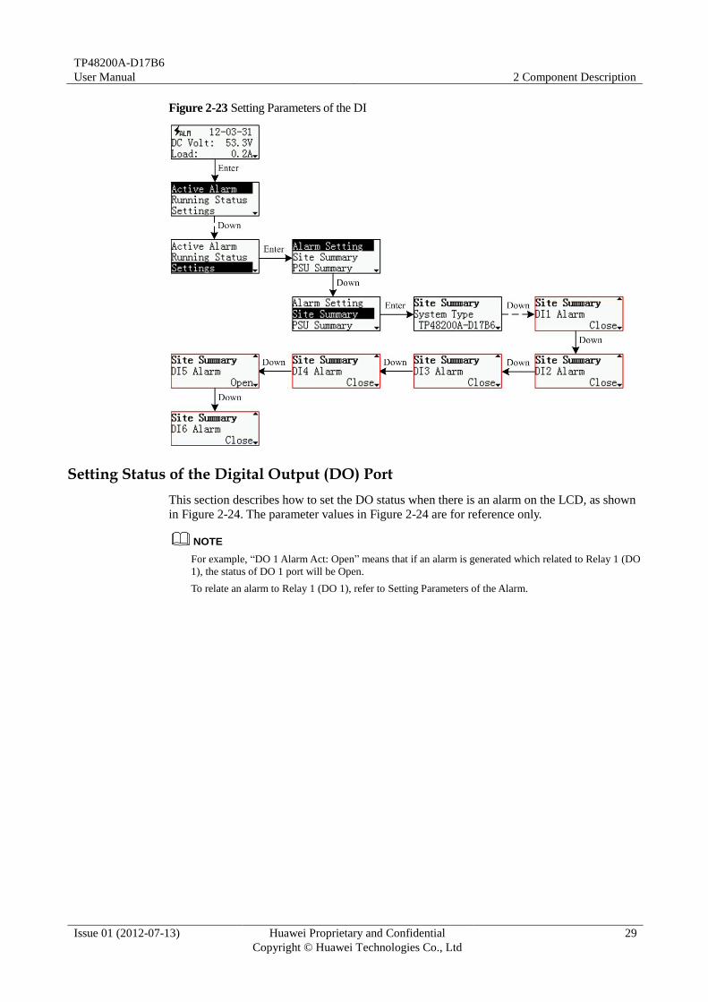
Setting Status of the Digital input (DI) Port
This section describes how to set the DI alarm status on the LCD, as shown in Figure 2-23.
The parameter values in Figure 2-23 are for reference only.
For example, “DI 1 Alarm: Close” means that if the status of DI 1 port is Close, the monitoring unit will
generate a DI 1 Alarm.
NOTE
TP48200A-D17B6
User Manual 2 Component Description
Issue 01 (2012-07-13) Huawei Proprietary and Confidential
Copyright © Huawei Technologies Co., Ltd
29
Figure 2-23 Setting Parameters of the DI
Setting Status of the Digital Output (DO) Port
This section describes how to set the DO status when there is an alarm on the LCD, as shown
in Figure 2-24. The parameter values in Figure 2-24 are for reference only.
For example, “DO 1 Alarm Act: Open” means that if an alarm is generated which related to Relay 1 (DO
1), the status of DO 1 port will be Open.
To relate an alarm to Relay 1 (DO 1), refer to Setting Parameters of the Alarm.
NOTE

TP48200A-D17B6
User Manual 2 Component Description
Issue 01 (2012-07-13) Huawei Proprietary and Confidential
Copyright © Huawei Technologies Co., Ltd
30
Figure 2-24 Setting Parameters of the DO
Setting Parameters of Alarm
This section describes how to set the alarm enable/disable, alarm level, related relay and
alarm delay time, as shown in Figure 2-25. The parameter values in Figure 2-25 are for
reference only.

TP48200A-D17B6
User Manual 2 Component Description
Issue 01 (2012-07-13) Huawei Proprietary and Confidential
Copyright © Huawei Technologies Co., Ltd
31
Figure 2-25 Setting Parameters of the Alarm
LCD Menu Hierarchy
Figure 2-26 shows the LCD main menu.
Figure 2-26 LCD menu hierarchy

TP48200A-D17B6
User Manual 2 Component Description
Issue 01 (2012-07-13) Huawei Proprietary and Confidential
Copyright © Huawei Technologies Co., Ltd
32
2.7.4 Web User Interface
You can perform the following operations over the Web UI:
View the system status, including the rectifier status, battery status, and active alarm
information.
Configure system parameters.
Configure network parameters, including IP addresses, host communications addresses
and baud rates under master/slave protocol.
Control the system, such as choosing battery boost or floating charge.
Add or delete users, and change user names and passwords.
Upgrade software online.
Query and export historical logs and alarms.
Configure alarm parameters, alarm severities, and the relationship between alarms and
dry contacts.
Set the system date and time, site and storage battery type, save, download, and upload
configuration files.
Query electronic label information.
Configure site information including date and site name and deal with configuration files
and so on.
Set the IP address, gateway, and subnet mask of the SMU on the LCD before logging into the
Web UI.
Login Web Page
Step 1 Connect an SMU to an Ethernet.
Step 2 Set the IP address, subnet mask, and gateway on the LCD based on those assigned by the
customer.
Step 3 Enter the IP address of the SMU in the Internet Explorer address box and press Enter.
Step 4 On the login page shown in Figure 2-27 set User Name to admin and Password to 001, and
then press Login.
----End

TP48200A-D17B6
User Manual 2 Component Description
Issue 01 (2012-07-13) Huawei Proprietary and Confidential
Copyright © Huawei Technologies Co., Ltd
33
Figure 2-27 Login page
Querying System Status
To view the information about Active Alarm, Site Summary, Rectifier Summary, Rectifier,
Battery Summary, Battery Summary, TCU Summary and Fan Group, please click System
Status, as shown in Figure 2-28.
Figure 2-28 System Status
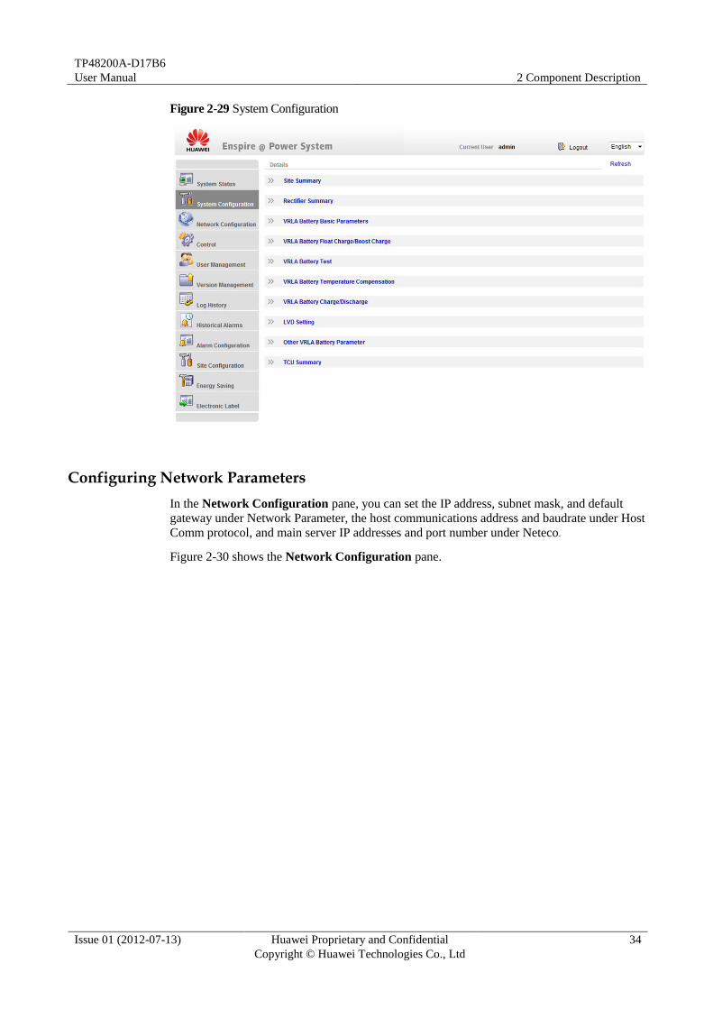
Configuring System Parameters
The user can configure Site Summary, Rectifier Summary, VRLA Battery Basic Parameters
and other parameters in the System Configuration pane, as shown in Figure 2-29.
TP48200A-D17B6
User Manual 2 Component Description
Issue 01 (2012-07-13) Huawei Proprietary and Confidential
Copyright © Huawei Technologies Co., Ltd
34
Figure 2-29 System Configuration
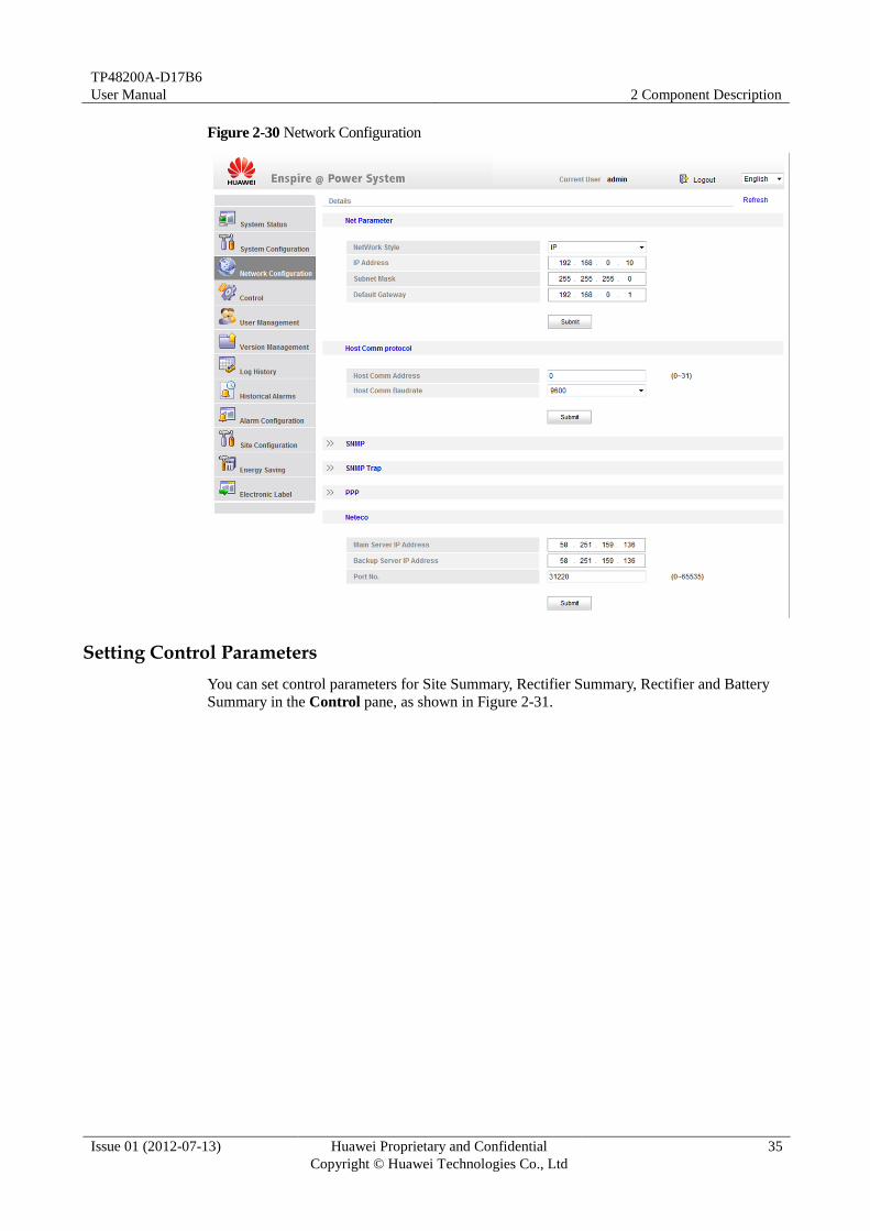
Configuring Network Parameters
In the Network Configuration pane, you can set the IP address, subnet mask, and default
gateway under Network Parameter, the host communications address and baudrate under Host
Comm protocol, and main server IP addresses and port number under Neteco.
Figure 2-30 shows the Network Configuration pane.
TP48200A-D17B6
User Manual 2 Component Description
Issue 01 (2012-07-13) Huawei Proprietary and Confidential
Copyright © Huawei Technologies Co., Ltd
35
Figure 2-30 Network Configuration
Setting Control Parameters
You can set control parameters for Site Summary, Rectifier Summary, Rectifier and Battery
Summary in the Control pane, as shown in Figure 2-31.

TP48200A-D17B6
User Manual 2 Component Description
Issue 01 (2012-07-13) Huawei Proprietary and Confidential
Copyright © Huawei Technologies Co., Ltd
36
Figure 2-31 Control
Managing Users
You can create and delete users and modify user information in the User Management pane,
as shown in Figure 2-32. Users are classified into three types: admin, engineer, and operator.
Different user types have different operation rights. Only admin users have user management
rights.
Figure 2-32 User Management
TP48200A-D17B6
User Manual 2 Component Description
Issue 01 (2012-07-13) Huawei Proprietary and Confidential
Copyright © Huawei Technologies Co., Ltd
37
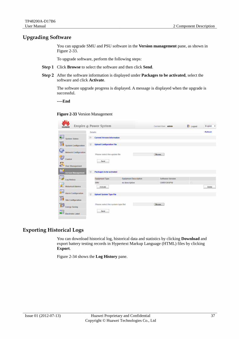
Upgrading Software
You can upgrade SMU and PSU software in the Version management pane, as shown in
Figure 2-33.
To upgrade software, perform the following steps:
Step 1 Click Browse to select the software and then click Send.
Step 2 After the software information is displayed under Packages to be activated, select the
software and click Activate.
The software upgrade progress is displayed. A message is displayed when the upgrade is
successful.
----End
Figure 2-33 Version Management
Exporting Historical Logs
You can download historical log, historical data and statistics by clicking Download and
export battery testing records in Hypertext Markup Language (HTML) files by clicking
Export.
Figure 2-34 shows the Log History pane.

TP48200A-D17B6
User Manual 2 Component Description
Issue 01 (2012-07-13) Huawei Proprietary and Confidential
Copyright © Huawei Technologies Co., Ltd
38
Figure 2-34 Log History
Exporting Historical Alarms
You can download historical alarms in the Historical Alarms pane, as shown in Figure 2-35.
To export historical alarms in HTML files, click Export. To clear historical alarms, click
Clean.
Figure 2-35 Historical Alarms

TP48200A-D17B6
User Manual 2 Component Description
Issue 01 (2012-07-13) Huawei Proprietary and Confidential
Copyright © Huawei Technologies Co., Ltd
39
Configuring Alarm Parameters
You can set alarm enabled, alarm severity, and relay in the Alarm Configuration pane, as
shown in Figure 2-36.
Figure 2-36 Alarm Configuration
Configuring Site Parameters
In the Site Configuration pane, you can set the system date and time, site information, and
operate configuration, as shown in Figure 2-37.

TP48200A-D17B6
User Manual 2 Component Description
Issue 01 (2012-07-13) Huawei Proprietary and Confidential
Copyright © Huawei Technologies Co., Ltd
40
Figure 2-37 Site Configuration
Energy Saving
You can set Basic Parameters, Control For Different Rates, Control for Exceeding Max Power,
Daily Electric Consume Mode, Monthly Electric Consume Mode in the Energy Saving pane,
as shown in Figure 2-38.
Figure 2-38 Energy Saving

TP48200A-D17B6
User Manual 2 Component Description
Issue 01 (2012-07-13) Huawei Proprietary and Confidential
Copyright © Huawei Technologies Co., Ltd
41
Reading Electronic Labels
You can query electronic label in the Electronic Label pane. To export electronic label
information in HTML files, click Export.
Figure 2-39 Electronic Labels

TP48200A-D17B6
User Manual 3 Safety Precautions
Issue 01 (2012-07-13) Huawei Proprietary and Confidential
Copyright © Huawei Technologies Co., Ltd
42
3 Safety Precautions
3.1 Overview
To minimize the risk of personal injury and damage to equipment, read and follow all the
precautions in this document before performing any installation or maintenance. The "NOTE",
"CAUTION", and "WARNING" marks in other documents do not represent all the safety
instructions. They are only supplements to the safety instructions. Only trained and qualified
personnel are allowed to install, operate, and maintain Huawei equipment, and they must
understand basic safety precautions to avoid hazards.
To ensure safety of humans and the equipment, pay attention to the safety symbols on the
equipment and all the safety instructions in this document. Huawei will not be liable for any
consequence caused by the violation of the safety operation regulations and design,
production, and usage standards.
The safety precautions described in this section are also applicable to other Huawei equipment.
3.2 Local Safety Regulations
When operating Huawei equipment, you must follow the local laws and regulations. The
safety instructions in this document are only supplements to the local laws and regulations.
3.3 Grounding Requirements
Equipment to be grounded must meet the following requirements:
When installing the device, always make the ground connection first and disconnect it at
the end.
Do not damage the ground conductor or operate the device in the absence of a properly
installed ground conductor. Conduct the electrical inspection carefully.
CAUTION
NOTE

TP48200A-D17B6
User Manual 3 Safety Precautions
Issue 01 (2012-07-13) Huawei Proprietary and Confidential
Copyright © Huawei Technologies Co., Ltd
43
The device (or system) must be connected permanently to the protection ground before
an operation. Before operating the device, check the electrical connection of the device
to ensure that it is securely grounded.
3.4 Human Safety Do not operate the device or cables during lightning strikes.
To avoid electric shock, do not connect safety extra-low voltage (SELV) circuits to
telecommunication network voltage (TNV) circuits.
Before operating the device, wear electrostatic discharge (ESD) clothes, ESD gloves, and
an ESD wrist strap.
Do not wear jewelry or watches when you operate the device.
In the case of fire, immediately leave the building or the equipment room, and turn on
the fire alarm bell or make an emergency call. Do not enter a building that is on fire.
The temperature of some equipment parts may be rather high. Do not touch the surface
of such equipment parts to avoid getting burn.
3.5 Equipment Safety The device must be fixed securely on the floor or to other immovable objects such as
walls and mounting racks before operation.
Do not block the ventilation while the device is operating.
Tighten the thumbscrews by using a tool after initial installation and subsequent access
to the panel.
After the installation, remove packing materials from the equipment area.
3.6 Electrical Safety
High Voltage
The high voltage power supply provides power for the device operation. Direct or indirect
contact (through damp objects) with high voltage and AC mains supply may result in fatal
danger.
Non-standard and incorrect high voltage operations may result in fire and electric shock.
The personnel who install the AC facility must be qualified to perform high voltage and
AC operations.
You must abide by the local rules and regulations when bridging and wiring AC cables.
During the installation of the AC power supply facility, follow the local safety
regulations.
DANGER

TP48200A-D17B6
User Manual 3 Safety Precautions
Issue 01 (2012-07-13) Huawei Proprietary and Confidential
Copyright © Huawei Technologies Co., Ltd
44
Dedicated tools must be used during high voltage and AC operations. Avoid using
ordinary tools.
When the operation is performed in a damp environment, ensure that the device is dry.
When water is found in the rack or the rack is damp, switch off the power supply
immediately.
High Electrical Leakage Ground the device before powering it on. Otherwise, personal injury or device damage
may be caused by high leakage current.
If a "high electrical leakage" tag is present on the power terminal of the device, you must
ground the device before powering it on.
Power Cable Do not install or remove power cables when the device is on. Transient contact between
the core of the power cable and the conductor may generate electric arcs or sparks, which
may cause fire or hurt human eyes.
Before installing or removing the power cable, turn off the power switch.
Before connecting a power cable, check that the label on the power cable is correct.
Power Output
All output circuits are evaluated as SELV circuits.
Outputs are energy hazards (>240 VA)
Electrostatic Discharge
The static electricity generated by human bodies may damage the electrostatic-sensitive
components on boards, for example, the large-scale integrated (LSI) circuits.
Human body movement, friction between human bodies and clothes, friction between
shoes and floors, or handling of plastic articles causes static electromagnetic fields on
human bodies. These static electromagnetic fields cannot be eliminated until the static is
discharged.
To prevent electrostatic-sensitive components from being damaged by the static on
human bodies, you must wear a well-grounded ESD wrist strap when touching the
device or handling boards or application-specific integrated circuits (ASICs).
CAUTION
CAUTION
TP48200A-D17B6
User Manual 3 Safety Precautions
Issue 01 (2012-07-13) Huawei Proprietary and Confidential
Copyright © Huawei Technologies Co., Ltd
45
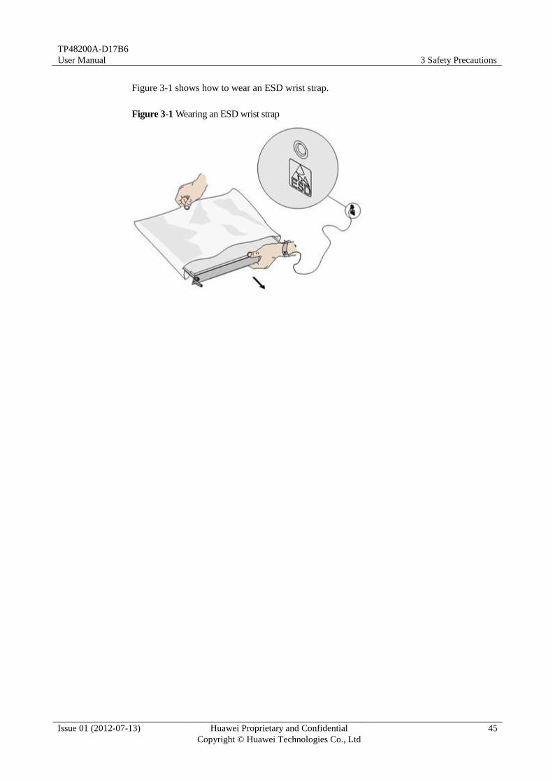
Figure 3-1 shows how to wear an ESD wrist strap.
Figure 3-1 Wearing an ESD wrist strap

TP48200A-D17B6
User Manual 4 Installation and Commissioning
Issue 01 (2012-07-13) Huawei Proprietary and Confidential
Copyright © Huawei Technologies Co., Ltd
46
4 Installation and Commissioning
The detailed installation refers to the TP48200A- D17B6 Quick Installation Guide.

TP48200A-D17B6
User Manual 5 Maintenance
Issue 01 (2012-07-13) Huawei Proprietary and Confidential
Copyright © Huawei Technologies Co., Ltd
47
5 Maintenance
5.1 Routine Maintenance
Maintain TP48200A-D17B6 periodically based on site requirements. The recommended
maintenance interval is 6 months. If faults are identified, clear them immediately.
The air filter is recommended to be maintained once a year before summer comes.
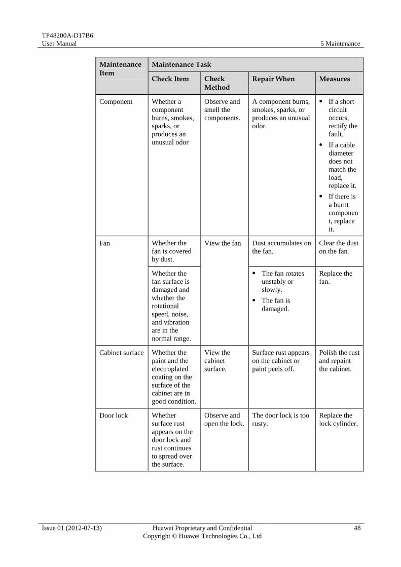
Table 5-1 Routine maintenance
Maintenance Item
Maintenance Task
Check Item Check Method
Repair When Measures
Output voltage Whether the
output voltage
of the DC PDU
is within the
range of –42 V
DC to –58 V
DC.
Measure the
voltage.
The voltage is
beyond the range of
–42 V DC to –58 V
DC.
Switch on
the circuit
breaker on
the DC
PDU, set
the
multimeter
to DC, and
then
measure
the output
voltage of
the DC
PDU.
TP48200A-D17B6
User Manual 5 Maintenance
Issue 01 (2012-07-13) Huawei Proprietary and Confidential
Copyright © Huawei Technologies Co., Ltd
48
Maintenance Item
Maintenance Task
Check Item Check Method
Repair When Measures
Component Whether a
component
burns, smokes,
sparks, or
produces an
unusual odor
Observe and
smell the
components.
A component burns,
smokes, sparks, or
produces an unusual
odor.
If a short
circuit
occurs,
rectify the
fault.
If a cable
diameter
does not
match the
load,
replace it.
If there is
a burnt
componen
t, replace
it.
Fan Whether the
fan is covered
by dust.
View the fan. Dust accumulates on
the fan.
Clear the dust
on the fan.
Whether the
fan surface is
damaged and
whether the
rotational
speed, noise,
and vibration
are in the
normal range.
The fan rotates
unstably or
slowly.
The fan is
damaged.
Replace the
fan.
Cabinet surface Whether the
paint and the
electroplated
coating on the
surface of the
cabinet are in
good condition.
View the
cabinet
surface.
Surface rust appears
on the cabinet or
paint peels off.
Polish the rust
and repaint
the cabinet.
Door lock Whether
surface rust
appears on the
door lock and
rust continues
to spread over
the surface.
Observe and
open the lock.
The door lock is too
rusty.
Replace the
lock cylinder.
TP48200A-D17B6
User Manual 5 Maintenance
Issue 01 (2012-07-13) Huawei Proprietary and Confidential
Copyright © Huawei Technologies Co., Ltd
49
Maintenance Item
Maintenance Task
Check Item Check Method
Repair When Measures
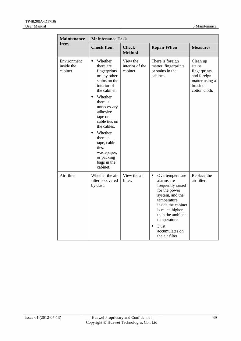
Environment
inside the
cabinet
Whether
there are
fingerprints
or any other
stains on the
interior of
the cabinet.
Whether
there is
unnecessary
adhesive
tape or
cable ties on
the cables.
Whether
there is
tape, cable
ties,
wastepaper,
or packing
bags in the
cabinet.
View the
interior of the
cabinet.
There is foreign
matter, fingerprints,
or stains in the
cabinet.
Clean up
stains,
fingerprints,
and foreign
matter using a
brush or
cotton cloth.
Air filter Whether the air
filter is covered
by dust.
View the air
filter.
Overtemperature
alarms are
frequently raised
for the power
system, and the
temperature
inside the cabinet
is much higher
than the ambient
temperature.
Dust
accumulates on
the air filter.
Replace the
air filter.

TP48200A-D17B6
User Manual 5 Maintenance
Issue 01 (2012-07-13) Huawei Proprietary and Confidential
Copyright © Huawei Technologies Co., Ltd
50
5.2 Troubleshooting
Common Faults
Table 5-2 Common faults and troubleshooting methods
Fault Type Fault Analysis Handling Method
AC phase loss AC input cable
fault
Grid fault or D.G.
fault
1. Check whether the AC input cable is
correctly and securely connected. If the
cable is not correctly and securely
connected, reconnect the cable. If the
insulation layer is aged, replace the cable.
2. Check whether the AC input voltage is
excessively low using a multimeter, and
check whether the AC undervoltage
(lower than 180V AC) alarm is
generated. If the AC input voltage is
excessively low and the AC undervoltage
alarm is generated, check whether there
is short-circuit or electric leakage on the
AC input loop. If there is short-circuit or
electric leakage, replace the cable.
3. If the AC input is the mains supply,
contact the mains supplier for
troubleshooting. If the AC input is from
the D.G., check the D.G. by referring to
the Diesel Generator User Manual.
AC power off AC input cable
fault
Grid fault or D.G.
fault
1. Check whether the AC input cable is
correctly and securely connected. If the
cable is not correctly and securely
connected, reconnect the cable.
2. Check whether the AC input switch is
OFF. If the AC input switch is OFF,
check whether faults such as short-circuit
or open circuit exist on the AC input
loop.
3. If the AC input is the mains supply,
contact the mains supplier for
troubleshooting. If the AC input is from
the D.G., check the D.G. by referring to
the Diesel Generator User Manual.
4. If the power-off duration is short, supply
DC power using batteries. If the
power-off duration is long, start other
systems for power supply.

TP48200A-D17B6
User Manual 5 Maintenance
Issue 01 (2012-07-13) Huawei Proprietary and Confidential
Copyright © Huawei Technologies Co., Ltd
51
Fault Type Fault Analysis Handling Method
AC overvoltage
and undervoltage
Improper setting
of monitoring unit
AC undervoltage
or overvoltage
threshold
Mains supply grid
fault or D.G. fault
1. Check whether the AC undervoltage or
overvoltage alarm threshold is properly
set. If the threshold is excessively high or
low, lower or raise the threshold
according to the actual conditions.
2. If the AC input is the mains supply,
contact the mains supplier for
troubleshooting. If the AC input is from
the D.G., check the D.G. by referring to
the Diesel Generator User Manual.
DC overvoltage or
DC undervoltage
Improper setting
of monitoring unit
DC undervoltage
or overvoltage
threshold
Rectifier module
fault
1. Check the alarm thresholds of the DC
overvoltage and undervoltage. If the
thresholds are not proper, reset the
thresholds according to the actual
conditions.
2. When the storage battery is powering the
load, remove all the rectifiers, and then
insert each rectifier one by one. If an
overvoltage alarm is generated after a
rectifier is inserted, the voltage of the
rectifier exceeds the upper threshold.
Then replace the rectifier.
Charging
overcurrent
Communication
failure between
the monitoring
unit and the
rectifier
Battery loop fault
1. Check whether the rectifier module is in
position or whether contact is proper. If
the monitoring unit is inserted in an
incorrect position, insert it correctly. If
the contact is not proper, remove and
then insert it.
2. Check whether the battery loop is
short-circuited or has other faults.
3. Check whether the batteries are faulty. If
the batteries are faulty, replace them.
Load shutdown Contactor fault
Excessively high
setting of
monitoring unit
load shutdown
voltage
Output
undervoltage due
to greater load
power than
configured
rectifier module
power
1. Check whether the contactor is faulty and
whether it can be connected and
disconnected. If the contactor is faulty,
replace it.
2. Check whether the monitoring unit load
shutdown voltage is set excessively high.
If it is set excessively high, set it
according to the actual situation.
3. Check whether the load power is higher
than the configured rectifier module
power. If the load power is higher than
the configured rectifier module power,
add a rectifier module. If the load power
exceeds the maximum supported power
of the system, lower the load power.

TP48200A-D17B6
User Manual 5 Maintenance
Issue 01 (2012-07-13) Huawei Proprietary and Confidential
Copyright © Huawei Technologies Co., Ltd
52
Fault Type Fault Analysis Handling Method
Battery shutdown Improper setting
of monitoring unit
battery parameters
Contactor fault
1. Check whether the mains supply is off or
the voltage of storage batteries is lower
than the “Battery Shutdown Voltage”.
2. Check whether the battery shutdown
permission is set.
3. Check whether the battery cables or the
connectors are faulty. If the cables or
connectors are faulty, replace them.
4. Check whether the contactor is faulty and
whether it can be connected and
disconnected. If the contactor is faulty,
replace it.
Battery fuse failure Battery loop fault
Contactor fault
Battery fault
1. Check whether cables of the battery loop
or connectors are faulty. If the cables or
connectors are faulty, replace them.
2. Check whether the contactor is faulty and
whether it can be connected and
disconnected. If the contactor is faulty,
replace it.
3. Check whether batteries are faulty. If the
batteries are faulty, replace them.
Ambient
overtemperature or
undertemperature
alarm
(The alarm is
generated only
when the
temperature sensor
is installed.)
Improper setting
of monitoring unit
temperature alarm
parameters
Overtemperature
or
undertemperature
in the shelter with
the temperature
sensor
Temperature
sensor fault
1. Check whether monitoring unit
temperature alarm thresholds are set
according to local conditions. If the
thresholds are not proper, set the
thresholds accordingly.
2. Check whether the temperature control
device in the shelter is faulty. If the
temperature control device is faulty,
repair it. The alarm is automatically
cleared when the temperature in the
shelter is adjusted to the proper range.
3. Check whether the temperature sensor is
faulty. If the temperature sensor is faulty,
replace it.
Ambient
overhumidity or
underhumidity
alarm
(The alarm is
generated only
when the humidity
sensor is installed.)
Improper setting
of monitoring unit
humidity alarm
parameters
Overhumidity or
underhumidity in
the shelter with
the humidity
sensor
Humidity sensor
fault
1. Check whether monitoring unit humidity
alarm thresholds are set according to
local conditions. If the thresholds are not
proper, set the thresholds accordingly.
2. If the alarm persists when the humidity is
proper, check whether the humidity
sensor is faulty.

TP48200A-D17B6
User Manual 5 Maintenance
Issue 01 (2012-07-13) Huawei Proprietary and Confidential
Copyright © Huawei Technologies Co., Ltd
53
Fault Type Fault Analysis Handling Method
Battery
overtemperature or
undertemperature
alarm
Battery cabin
overtemperature
Improper setting
of monitoring unit
battery
temperature alarm
parameters
Battery charging
overcurrent
Temperature
sensor fault
1. Check whether monitoring unit battery
temperature alarm thresholds are properly
set. If the thresholds are not proper, set
the thresholds accordingly.
2. Check whether the temperature in the
battery room is excessively high. If the
temperature is excessively high, the
alarm can be cleared when the
temperature is lowered.
3. Check the charging current. If the current
is excessively strong, switch equalized
charging to float charging and check
whether the charging current is
weakened. If the charging current is still
excessively strong, adjust the current
limit to reduce the charging current. If the
preceding steps do not work, replace the
faulty battery.
4. Check whether the temperature sensor is
faulty. If the temperature sensor is faulty,
replace it.
Door alarm
Opened cabinet
door
Door status sensor
fault
1. The alarm is cleared after the cabinet
door is closed.
2. If the alarm persists after the cabinet door
is closed, check whether the door status
sensor is faulty.
Water immersion
alarm
(The alarm is
generated only
when the water
sensor is installed.)
Shelter water
accumulation
Water sensor fault
1. Check whether the floor of the shelter is
wet. If the floor is wet, use a cotton cloth
to wipe the floor and ensure it is dry or
use other dehumidifiers.
2. If the alarm persists after the water is
drained, check whether the water sensor
is faulty.
Smoke alarm
(The alarm is
generated only
when the smoke
sensor is installed.)
Smoke in the
shelter
Smoke sensor
fault
1. Check whether the smoke caused by fire
pervades in the shelter. If there is fire,
extinguish the fire and ventilate the
shelter.
2. If the alarm persists when there is no
smoke, check whether the smoke sensor
is faulty.

TP48200A-D17B6
User Manual 5 Maintenance
Issue 01 (2012-07-13) Huawei Proprietary and Confidential
Copyright © Huawei Technologies Co., Ltd
54
Fault Type Fault Analysis Handling Method
Rectifier module
fault
Poor contact of the
rectifier module
Rectifier module
fault
1. Check whether the alarm indicator on the
panel of the rectifier module is on. If the
alarm indicator is on, remove the rectifier
module and insert the rectifier module
after the indicator is off.
2. Disconnect AC input to the rectifier
module and restart the rectifier module
later on. If the alarm persists, replace the
rectifier module.
Rectifier module
shutdown
Rectifier module
protection
Input overvoltage
or undervoltage of
the rectifier
module
Rectifier module
fault
1. Check whether the mains voltage is over
the AC overvoltage threshold (300 V) of
the rectifier module or below the AC
undervoltage threshold (85 V). For the
power supply network with long-time
overvoltage or undervoltage, negotiate
with the maintenance personnel of the
electricity department to improve the
power supply network.
2. If the alarm persists when the input
voltage of the rectifier module is proper,
check whether the rectifier module is
proper. If the rectifier module is faulty,
replace it.
Communication
Failure between
rectifier and
monitoring unit
Signal cable
connection fault of
the rectifier
module
Rectifier module
out of position
Poor contact of the
rectifier module
Rectifier module
fault
1. Check whether the rectifier module is in
position or whether contact is proper. If
the contact is not proper, remove and
then insert it.
2. If the alarm persists, replace the rectifier
module.
D.G. fault DG signal cable
fault
Improper setting
of the monitoring
unit
D.G. fault
1. Check whether the signal cable of the DG
is correctly and securely connected. If the
signal cable is not correctly and securely
connected, connect it correctly.
2. Check whether the start permission of the
DG in the monitoring unit is set to NO
and whether the diesel generator is
started manually. If the permission is set
to NO and the DG is started manually,
this is normal. The alarm is cleared after
the DG is shut down.
3. Check whether the DG is faulty by
referring to the Diesel Generator User Guide delivered with the DG.

TP48200A-D17B6
User Manual 5 Maintenance
Issue 01 (2012-07-13) Huawei Proprietary and Confidential
Copyright © Huawei Technologies Co., Ltd
55
Fault Type Fault Analysis Handling Method
Load Fuse Alarm The load fuse is
faulty.
Load circuit
breaker set to OFF
1. Check whether the load fuse detection
cable is securely connected. If the cable
is not connected securely, connect it
correctly.
2. Check whether the load circuit breaker is
in the OFF position. If it is, switch it to
the ON position.
3. Check whether the load fuse is damaged.
Use a multimeter to measure the voltage
at both ends of the fuse. If the voltage is
close to 0 V, the fuse is normal.
Otherwise, the fuse is blown. Replace the
fuse.
4. If the alarm persists after the fuse is
replaced, check the new fuse. If the new
fuse is blown or the load circuit breaker
is automatically switched to the OFF
position, the load power on this route
may be excessive or a short circuit may
occur. In this case, you need to rectify the
fault on this load loop.
AC surge protector
fault
AC surge
protector fault
User interface
module fault
1. Check the observation window on the AC
surge protector. If the color of the
window is red, replace the surge
protector.
2. Check whether the fault detection cables
of the AC surge protector are correctly
connected or whether the cables are in
good condition. If the cables are not in
good condition, replace and reconnect
them.
3. If the cable connection is proper, it
indicates that the alarm loop is faulty.
Replace the user interface module.
DC surge protector
fault
DC surge
protector fault
User interface
module fault
1. Check whether the fault detection cables
of the DC surge protector are correctly
and securely connected. If the cables are
not correctly and securely connected,
reconnect them.
2. If the cables are correctly connected,
replace the DC surge protector.
3. If the alarm persists, it indicates that the
alarm loop is faulty. Replace the user
interface module.
TP48200A-D17B6
User Manual 5 Maintenance
Issue 01 (2012-07-13) Huawei Proprietary and Confidential
Copyright © Huawei Technologies Co., Ltd
56
AC SPD
Observe the indication window on the surge protection module. If the indication window
turns red, the surge protection module is damaged. In this case, replace the surge protection
module. If the indication window remains green, the SPD runs properly.
Circuit Breaker
The circuit breaker fault is usually caused by overcurrent or short circuits. To check whether a
circuit break is faulty, perform the following steps:
Step 1 Switch the circuit breaker to the ON position.
Step 2 Measure the resistance at the two ends of the circuit breaker using a multimeter. If the
resistance is infinity, the circuit breaker is damaged.
----End
DC Contactor
Table 5-3 DC contactor description
Position Type Check Method
Load
Disconnected
Branch
Closed type, (when the
contactor without electricity,
the state is closed)
When there is no voltage at the control
poles of the contactor, check whether the
input and output poles of the contactor
are proper by using the multimeter. For
example, the contactor of the power
system is closed type contactor as shown
in Figure 5-1. When there is no voltage
at control poles 1 and 2 but measuring
shows that the input and output poles 3
and 4 are disconnected, it indicates that
the contactor is faulty.
When there is voltage at the control
poles of the contactor, check whether the
input and output poles of the contactor
are proper by using the multimeter. For
example, the contactor of the power
system is a closed type contactor as
shown in Figure 5-1. When there is
voltage at control poles 1 and 2 but
measuring shows that the input and
output poles 3 and 4 are connected, it
indicates that the contactor is faulty.

TP48200A-D17B6
User Manual 5 Maintenance
Issue 01 (2012-07-13) Huawei Proprietary and Confidential
Copyright © Huawei Technologies Co., Ltd
57
Position Type Check Method
Battery Fuse
or battery
circuit breaker
Branch
Open type, (when the
contactor without electricity,
the state is open)
When there is no voltage at the control
poles of the contactor, check whether the
input and output poles of the contactor
are proper by using the multimeter. For
example, the contactor of the power
system is an open type contactor as
shown in Figure 5-1. When there is no
voltage at control poles 1 and 2 but
measuring shows that the input and
output poles 3 and 4 are connected, it
indicates that the contactor is faulty.
When there is voltage at the control
poles of the contactor, check whether the
input and output poles of the contactor
are proper by using the multimeter. For
example, the contactor of the power
system is an open type contactor as
shown in Figure 5-1. When there is
voltage at control poles 1 and 2 but
measuring shows that the input and
output poles 3 and 4 are disconnected, it
indicates that the contactor is faulty.
Figure 5-1 DC contactor
Rectifier
The rectifier is damaged if either of the following conditions is not met:
The Run indicator of the rectifier is steady on and the Fault indicator is off when the
rectifier does not communicate with the monitoring unit and the input AC voltage is
around 220 V. The rectifier outputs power normally.
The monitoring unit can perform control on the charge mode (boost charge or floating
charge) and current for the rectifier when the rectifier communications cable is properly
connected and the rectifier communicates with the monitoring unit normally.
TP48200A-D17B6
User Manual 5 Maintenance
Issue 01 (2012-07-13) Huawei Proprietary and Confidential
Copyright © Huawei Technologies Co., Ltd
58
Monitoring Unit
If any of the following occurs, the monitoring unit is faulty:
The monitoring unit breaks down or fails to start, or its LCD or keyboard fails.
The monitoring unit does not generate an alarm when a fault occurs in the system.
The monitoring unit generates an alarm (false alarm) when the system runs properly.
Communication between the monitoring unit and all subordinate equipment is
interrupted.
The monitoring unit fails to control or monitor all the modules when these modules run
properly and communications cables are connected properly.
The monitoring unit fails to monitor or control AC or DC distribution when AC/DC
power is distributed normally and communications cables are connected properly.
Parameters cannot be set or operating information cannot be viewed on the monitoring
unit.
5.3 Component Replacment
Load disconnection is prohibited when you replace the main components. Take measures to ensure
that important loads are always connected during the replacement. For example, keep the circuit
breaker of important loads set to ON and storage batteries and AC input are not cut off.
If a load must be disconnected, ask for the customer's prior permission.
The rectifier and the monitoring unit are hot-swappable.
Replacing the rectifier
To replace the rectifier, perform the following steps:
Step 1 Loosen the screws on the rectifier panel using a flat-head screwdriver.
Step 2 Pull the handle of the rectifier outwards, and then remove the rectifier from the plug-in
subrack, as shown in Figure 5-2.
Step 3 Loosen the screws on the handle and pull out the handle, and then insert the rectifier into the
corresponding slot in the plug-in subrack.
Step 4 Slide the rectifier into the plug-in subrack slowly along the guide rails. Then, lock the handle.
Step 5 Tighten the screws on the handle, as shown in Figure 5-3.
----End

TP48200A-D17B6
User Manual 5 Maintenance
Issue 01 (2012-07-13) Huawei Proprietary and Confidential
Copyright © Huawei Technologies Co., Ltd
59
Figure 5-2 Removing the old rectifier
Figure 5-3 Installing the new rectifier
Replacing the monitoring unit
To replace the monitoring unit, perform the following steps:
Step 1 Push the locking latch left.
Step 2 Remove the old monitoring unit.
Step 3 Insert a new monitoring unit.
Step 4 Push the locking latch right.
Step 5 Set parameters on the monitoring unit panel by referring the Quick Installation Guide.
----End

TP48200A-D17B6
User Manual 5 Maintenance
Issue 01 (2012-07-13) Huawei Proprietary and Confidential
Copyright © Huawei Technologies Co., Ltd
60
Figure 5-4 Removing the old monitoring unit
Figure 5-5 Installing the new monitoring unit
Replacing the UIM
To replace the UIM, perform the following steps:
Step 1 Remove signal cables from the UIM.
Step 2 Loosen the screws on the UIM panel using a Phillips screwdriver.
Step 3 Pull the UIM outwards and disconnect the cables.
Step 4 Connect the cables to a new UIM and insert the new UIM.
Step 5 Tighten the screws on the handle.
Step 6 Reinstall the signal cables.
----End
Figure 5-6 Removing the old UIM

TP48200A-D17B6
User Manual 5 Maintenance
Issue 01 (2012-07-13) Huawei Proprietary and Confidential
Copyright © Huawei Technologies Co., Ltd
61
Figure 5-7 Installing the new UIM
Replacing the Fan assembly
To replace the fan assembly, perform the following steps:
Step 1 Disconnect the power cable for the fan assembly. The power cable is on the back end of the
UIM02D.
Figure 5-8 Disconnect the power cable
Step 2 Loosen the captive screws from the panel of the fan assembly.
Step 3 Pull the fan assembly out along the guide rails. When the fan assembly is almost out of the
cabinet, hold the bottom of the fan assembly with one hand and the handle with the other until
the fan assembly is removed from the cabinet.
Step 4 Install the new fan drawer as follows: Insert the new fan assembly into the guide rails by
holding the bottom of the fan assembly with one hand and the handle with the other hand.
Then, push the fan assembly by holding two handles on the fan drawer along the guide rails
until the fans start to work.
Step 5 Fasten the captive screws on the panel.

TP48200A-D17B6
User Manual 5 Maintenance
Issue 01 (2012-07-13) Huawei Proprietary and Confidential
Copyright © Huawei Technologies Co., Ltd
62
----End
Figure 5-9 Removing the fan assembly
Figure 5-10 Installing the fan assembly
Replacing the HAU
To replace the HAU, perform the following steps:
Step 1 Turn off the HEATER power switch on the AC PDU.
Step 2 Record the connections of the cables on the HAU, and remove these cables.
Step 3 Remove the four screws on both sides of the faulty HAU, and remove the faulty HAU (with
the mounting ears).
Step 4 Remove the four screws from the mounting ears on both sides of the faulty HAU, and remove
and reserve the mounting ears.
Step 5 Reinstall the mounting ears removed from the faulty HAU on the new HAU.
Step 6 Install the new HAU with the mounting ears on the cabin.

TP48200A-D17B6
User Manual 5 Maintenance
Issue 01 (2012-07-13) Huawei Proprietary and Confidential
Copyright © Huawei Technologies Co., Ltd
63
Step 7 Reconnect the cables to the new HAU based on the cable connection records.
----End
Figure 5-11 Removing the HAU
Figure 5-12 Installing the HAU

TP48200A-D17B6
User Manual 5 Maintenance
Issue 01 (2012-07-13) Huawei Proprietary and Confidential
Copyright © Huawei Technologies Co., Ltd
64
Replacing the Air filter
To replace the air filter, perform the following steps:
Step 1 Record the installation direction of the air filter. Wrong installation of an air filter lead to air
filtering failures.
Step 2 Loosen the screws with the crosshead screwdriver and then remove the air filter.
Step 3 Install the air filter in the original position and fasten the screws with the crosshead
screwdriver.
----End
Figure 5-13 Removing the air filter
Figure 5-14 Installing the air filter
Replacing the AC SPD
To replace the AC SPD, perform the following steps:

TP48200A-D17B6
User Manual 5 Maintenance
Issue 01 (2012-07-13) Huawei Proprietary and Confidential
Copyright © Huawei Technologies Co., Ltd
65
Step 1 Remove the faulty SPD.
Step 2 Insert the new SPD.
----End
Figure 5-15 Replacing the AC SPD
Replacing the Lamp
To replace a lamp, perform the following steps:
Step 1 Turn OFF the lamp switch which is on the power cable connected to the lamp.
Step 2 Take down the cables from terminal block.
Step 3 Loosen the lamp and take off it from the shelf.
Step 4 Install a new lamp on the shelf.
Step 5 Connect cables to the terminal block.
Step 6 Turn ON the lamp switch which is on the power cable connected to the lamp.
----End

TP48200A-D17B6
User Manual 5 Maintenance
Issue 01 (2012-07-13) Huawei Proprietary and Confidential
Copyright © Huawei Technologies Co., Ltd
66
Figure 5-16 Removing the lamp
Figure 5-17 Installing the lamp
Replacing the Door lock cylinder
To replace the lock cylinder, perform the following steps:
Step 1 Open the door lock using a key to the degree as shown in the following figure.
Step 2 Unscrew the lock cylinder to be replaced using a Phillips screwdriver.
Step 3 Secure a new lock cylinder using screws.
----End
Figure 5-18 Replacing the lock cylinder

TP48200A-D17B6
User Manual A Technical Specifications
Issue 01 (2012-07-13) Huawei Proprietary and Confidential
Copyright © Huawei Technologies Co., Ltd
67
A Technical Specifications
Table A-1 Technical specifications
Category Item Specifications
Environmental
conditions
Operating
temperature
–20ºC to +45ºC (–4ºF to +113.0ºF)
Storage
temperature
–40°C to +70°C (–40°F to +158°F)
Transportation
temperature
–40°C to +70°C (–40°F to +158°F)
Operating
humidity 5%–95% RH (non-condensing)
Storage humidity 5%–95% RH (non-condensing)
Altitude <4000 m (<13123.2 ft)
When the altitude ranges from 2000 m (6561.6 ft) to
4000 m (13123.2 ft), the operating temperature is
derated by 1ºC (1.8ºF) for each additional 200 m
(656.16 ft).
AC input Input mode Three phase or single phase
Input voltage 346VAC to 415V AC/200V AC to 240V AC
Rated frequency 50/60 Hz
Power factor ≥ 0.99 (50% load or more)
DC output Output voltage
range
-42 V DC to -58V DC
Default output
voltage
-53.5 V DC
Maximum output
power
12KW
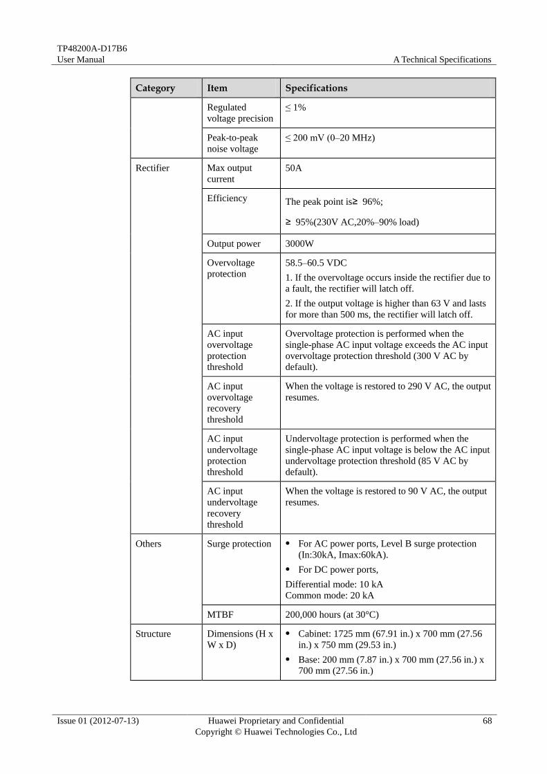
TP48200A-D17B6
User Manual A Technical Specifications
Issue 01 (2012-07-13) Huawei Proprietary and Confidential
Copyright © Huawei Technologies Co., Ltd
68
Category Item Specifications
Regulated
voltage precision
≤ 1%
Peak-to-peak
noise voltage
≤ 200 mV (0–20 MHz)
Rectifier
Max output
current
50A
Efficiency The peak point is≥ 96%;
≥ 95%(230V AC,20%–90% load)
Output power 3000W
Overvoltage
protection 58.5–60.5 VDC
1. If the overvoltage occurs inside the rectifier due to
a fault, the rectifier will latch off.
2. If the output voltage is higher than 63 V and lasts
for more than 500 ms, the rectifier will latch off.
AC input
overvoltage
protection
threshold
Overvoltage protection is performed when the
single-phase AC input voltage exceeds the AC input
overvoltage protection threshold (300 V AC by
default).
AC input
overvoltage
recovery
threshold
When the voltage is restored to 290 V AC, the output
resumes.
AC input
undervoltage
protection
threshold
Undervoltage protection is performed when the
single-phase AC input voltage is below the AC input
undervoltage protection threshold (85 V AC by
default).
AC input
undervoltage
recovery
threshold
When the voltage is restored to 90 V AC, the output
resumes.
Others Surge protection For AC power ports, Level B surge protection
(In:30kA, Imax:60kA).
For DC power ports,
Differential mode: 10 kA
Common mode: 20 kA
MTBF 200,000 hours (at 30°C)
Structure Dimensions (H x
W x D)
Cabinet: 1725 mm (67.91 in.) x 700 mm (27.56
in.) x 750 mm (29.53 in.)
Base: 200 mm (7.87 in.) x 700 mm (27.56 in.) x
700 mm (27.56 in.)
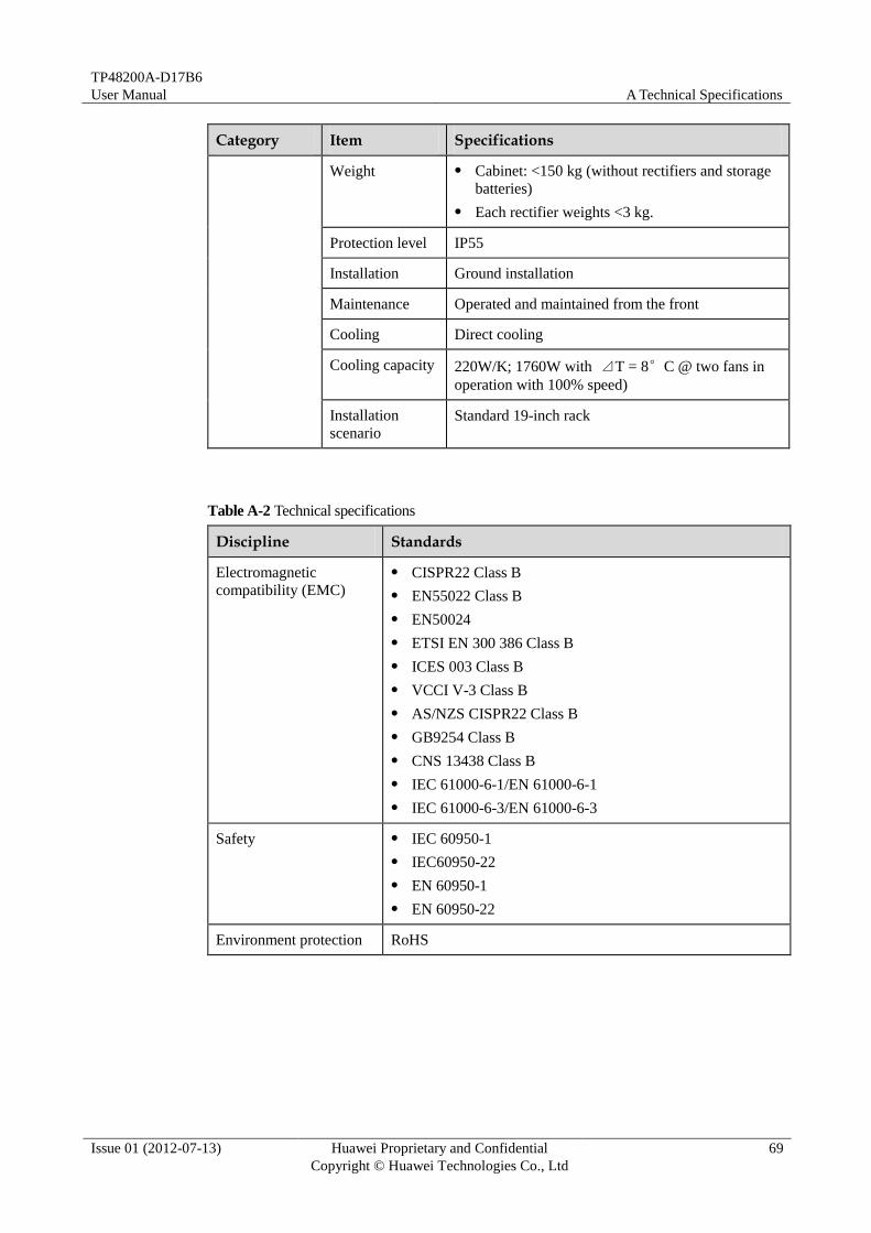
TP48200A-D17B6
User Manual A Technical Specifications
Issue 01 (2012-07-13) Huawei Proprietary and Confidential
Copyright © Huawei Technologies Co., Ltd
69
Category Item Specifications
Weight Cabinet: <150 kg (without rectifiers and storage
batteries)
Each rectifier weights <3 kg.
Protection level IP55
Installation Ground installation
Maintenance Operated and maintained from the front
Cooling Direct cooling
Cooling capacity 220W/K; 1760W with ⊿T = 8°C @ two fans in
operation with 100% speed)
Installation
scenario
Standard 19-inch rack
Table A-2 Technical specifications
Discipline Standards
Electromagnetic
compatibility (EMC)
CISPR22 Class B
EN55022 Class B
EN50024
ETSI EN 300 386 Class B
ICES 003 Class B
VCCI V-3 Class B
AS/NZS CISPR22 Class B
GB9254 Class B
CNS 13438 Class B
IEC 61000-6-1/EN 61000-6-1
IEC 61000-6-3/EN 61000-6-3
Safety IEC 60950-1
IEC60950-22
EN 60950-1
EN 60950-22
Environment protection RoHS

TP48200A-D17B6
User Manual B Acronyms and Abbreviations
Issue 01 (2012-07-13) Huawei Proprietary and Confidential
Copyright © Huawei Technologies Co., Ltd
70
B Acronyms and Abbreviations
A
AC PDU Alternating Current Power Distribution Unit
ASIC Application-Specific Integrated Circuit
ATS Automatic Transfer Switch
D
DC PDU Direct Current Power Distribution Unit
DI Digital Input
DO Digital Output
E
EMS Element Management System
H
HAU Heater Assembly Unit
I
IEC International Electrotechnical Commission
L
LED Light Emitting Diode
LSI Large-scale Integration
O

TP48200A-D17B6
User Manual B Acronyms and Abbreviations
Issue 01 (2012-07-13) Huawei Proprietary and Confidential
Copyright © Huawei Technologies Co., Ltd
71
OPEX Operational Expenditure
P
PDU Power Distribution Unit
S
SELV Safety Extra-low Voltage
SMU Site Monitoring Unit
SPD Surge Protection Device
T
TCU Temperature Control Unit