Embed Size (px)
Citation preview


Contents
Introduction
Injection Moulding
Equipment 3 Screw Design 3 Nozzles 3 Pre-drying 3 Mould Design 3 Gates 3 Runners 4 Gates & Venting 4 Shrinkage 4 Ejection 4 Mould Cooling 5
Process Parameters
SEBS Based Compound 5 SBS Based Compound 6
Extrusion
SEBS Based Compound 8 SBS Based Compound 10
2

IntroductionThe selected thermoplastic elastomer (TPE) material does not acquire its fi nal properties until after it has been processed, i.e. the design/geometry of the part and the method of processing, together with the selected material, will determine the fi nal properties of the product.
This process guide is intended to be advisory and help you when designing your tool and when processing TPE. However, we can provide you with support in tooling design, and help to optimise your process and thus reduce your fi nished part’s costs.
Injection MouldingDryfl ex, Mediprene and Lifofl ex thermoplastic elastomers are widely used for producing injection moulded parts with very high elasticity and fl exibility. However, it must be borne in mind that these properties are affected by the design of the parts and the material fl ow.
The physical characteristics are different in different directions (at right angles and along the direction of injection), i.e. the material is anisotropic. Under normal process conditions, the effects of molecular orientation are thus exhibited in the TPE material. This orientation is a function of the shear to which the molten polymer is subjected and it results in a higher modulus of elasticity and rigidity at right angles to the direction of fl ow.
By using process parameters that minimize shear, such as lower injection pressure, velocity and higher working temperature, the orientation effects can be minimized.
The degree of orientation is also affected by the mould design. The following factors minimize the orientation:• Largest practicable gate.• Gate location that minimizes the fl ow distance in the cavity.• Shot blasted or electrical discharge machined (EDM) instead of polished surface.
If the injection moulding temperature used is too low, there will be a serious risk of cold fl ow in the part, which will lead to poor strength.
EquipmentDryfl ex, Mediprene and Lifofl ex can be processed in most conventional injection moulding machines. These may contain one or several cavities. The number of cavities should be limited to achieve reliable production. It is important that the used injection-moulding machine is not too large. A recommendation is that at least 30% of the shot volume of the machine should be delivered in every shot.
Screw DesignMost injection moulding machines are equipped with universal screws that have a compression ratio of between 2:1 and 3:1, a 60-degree tip angle and some form of reverse fl ow inhibitor. Such screws are excellent for processing our TPEs. Special screws with short sections and higher compression ratios (3:1 to 4:1) may be good at low screw speeds.
NozzlesMost nozzle types can be used. Dryfl ex, Mediprene and Lifofl ex based on SEBS may remain stationary in the nozzle for a short period of time, since the material does not degrade at normal process temperatures and does not give rise to high gas pressures. On the other hand,
Dryfl ex, Mediprene and Lifofl ex based on SBS must not remain stationary in the nozzle for any length of time, since the material is more sensitive to thermooxidative degradation, i.e. it is broken down more easily by heat in the presence of atmospheric oxygen.
Pre-dryingPre-drying is not necessary, since Dryfl ex, Mediprene and Lifofl ex does not absorb moisture under normal storage conditions. If moisture should nevertheless occur, this will normally be evaporated in the mould and will be expelled through the air vent.
Mould DesignDryfl ex, Mediprene and Lifofl ex can be processed easily and economically in most conventional moulds and it can often be injected into moulds made for other materials, with limited modifi cations or none at all. However, some aspects should be borne in mind when the mould is designed for processing SBS and SEBS. In the design of the part, wide variations in material thickness should be avoided and efforts should also be made to provide radii at all edges and tips. Also avoid long, thin cores, since it is diffi cult to restrict the temperature.
A polished mould surface causes vacuum between the mould wall and the part, since the material being injected forces the air ahead of it. This phenomenon leads to the part being gripped in the mould by suction. A coarser surface, such as a shot blasted surface or one produced by EDM, improves the release properties.
GatesStandard gates with a draft angle of 2.5 degrees perform satisfactorily. However, the type of gate extractor should be decided on the basis of the material grade. For the soft grades, it is advisable to use extractors of the reverse cone or “fi nger” type which give back draft. Tunnel or fi lm gates are the usual gate types. More than one gate per stripper should be avoided since homogenization problems may occur. Figure 1 below shows an example of a good gate location.
Figure 1. Gate Location
3

RunnersCylindrical runners between the gate and the cavity inlet are the best solution, since the surface area is smaller than the one of, for example, a semi-circular runner with the same cross sectional area.
Secondary runners should also be cylindrical and should be of somewhat smaller diameters. If possible they should also branch off at right angles from the primary runner. If balanced fl ow is required, all secondary runners should be of the same length. Cold slugs should be avoided if the primary runner is made to continue a little way after the branch-off point, see fi gure 2 below.
Figure 2. Cold slug
In order to shorten the cycle time and to avoid re-using of the inlet and the runner systems, insulated or heated runner systems can be used for parts that have thin cross sections. Hot runner systems should be larger than cold runner systems, in order to maintain the mould pressure constant. The lowest temperature of the material in the runner, during unloaded parts of the cycle, should be around 175°C for SBS material and around 185°C for SEBS based materials.
Gates and VentingDryfl ex, Mediprene and Lifofl ex TPEs will produce good results when they are injection moulded with normal gates conforming to conventional design practice. Different gates are shown in fi gure 3.
A general rule is that the gate should be just big enough to fi ll the mould. The volume in the gate runners (hot runners) should be as small as possible. If the volume is too large in relation to the part there is a risk of cold fl ow, which will result in that the maximum strength will not be achieved. The gate should be as short as possible but with adequate sealing effect. Gates should be located in areas dictated by conventional design principles. To achieve the best surface, the gate should be located so that the melt meets obstacles or resistance immediately after the gate. For very thin parts, a fi lm gate or several gates should be used. The gate should be located in the thinnest area of the part, in order to minimize the risk of inhomogeneous material. Important is that the part is inspected by pulling by hand, please compare with the data sheet values.
Since Dryfl ex, Mediprene and Lifofl ex should be injection moulded at normal to high injection speeds, venting is necessary. A vent groove depth of 0.01 to 0.02 mm is generally suffi cient.
ShrinkageWhen a mould is being designed, consideration must be given to the shrinkage properties, in the same way as for other thermoplastic ma-terials. For a SBS material with a PS base, the shrinkage is between 0.4% and 1%, while for a SBS with PP base, it is between 1.0% and 2.5%. The shrinkage of SEBS material is also between 1.0% and 2.5%. The shrinkage depends principally on the material grade, the type of application and the location of the gate.
EjectionTo allow for fully automatic operation, the tool has different types of ejectors. Since Dryfl ex, Mediprene and Lifofl ex have a high surface friction and since some of the materials are soft and fl exible, the ejec-tor system should be closely studied. The design should be based on the specifi c product and, above all, the hardness. Ejector plates are generally recommended for soft grades. Air is often used for ejecting deep-drawn parts. The use of compressed air may facilitate mechani-cal ejection by eliminating the vacuum.
If only ejector pins are used, they should be as large as possible and should act on the sections of the part that are stiffest and provide the greatest assistance. Normal ejector systems perform satisfactorily on the harder compounds.
Figure 3. Examples of different gates.
4
Injection VelocityThe viscosity of the SEBS material is more dependent on the shear rate and less dependent on the temperature than the viscosity of SBS material, which in turn, is more dependent on the shear rate than thermoplastics in general. This offers benefi ts in the form of short cooling times and ease of controlling the process.
Due to the strong viscosity/shear rate relationship, a high injection velocity is desirable for SEBS based materials to facilitate fi lling of the mould. Air inclusion at high injection velocities does not pose any problems, provided that the mould has suffi cient venting. The “follow-up cushion” should be as small as possible in order to avoid follow-up packing and unsightly gates.
Screw Speeds and BackpressureNormal screw speeds are between 25 and 75 rpm and should be adjusted so that plasticizing will be concluded just before the next shot. The recommended backpressure should be just enough to ensure that no leakage will occur in the mould after the shot.
Holding Time and PressureAs in the case of most thermoplastic materials, the holding time and pressure must be in balance in order to prevent shrink marks due to reverse fl ow at the gate or warp age due to overfi lling.
Because of the elastomeric nature of Dryfl ex, Mediprene and Lifofl ex, overfi lling is more likely to cause problems than reverse fl ow. Short holding times and low holding pressures are therefore recommended to prevent these effects.
Clamping PressureHigh clamping pressures are seldom needed. Depending on the mould size and design the mould pressure may vary between 25 and 45 MPa. This is suffi cient for keeping the mould closed and to prevent fl ash on the product.
Cycle Time/Cooling TimeDue to the quick solidifi cation process the cooling time is generally short compared to other materials. The cycle time is dependent on the size and design of the part. Typical values are:
Sections up to 2 mm: 15 - 25 sSections between 2 and 6 mm: 30 - 60 s
Mould TemperatureFor SEBS material the mould temperature should normally be between 30 and 60°C. These higher temperatures facilitate fl ow into the mould, ensure complete fi lling at reduced injection pressures and they also facilitate a uniform surface without signifi cant increases in the cycle time.
MiscellaneousSince SEBS compounds have excellent thermal stability, a cleaning of the cylinder after a stoppage is unnecessary. SEBS compounds have been held in injection moulding machines for more than two hours at process temperature without detectable degradation. If cleaning is required, HDPE or PP can be employed.
Dryfl ex, Mediprene and Lifofl ex are fully recyclable. Material, which is to be regenerated, can be mixed in any proportions with new material. Recommended is however 10 - 25%. Grinding of soft compounds demands very sharp knives or considerable cooling. Typical process parameters for SEBS are given in Table 1 on page 7.
A mould surface produced by EDM or by shot blasting is recommended for best release. This since this surface fi nish enables air to be admitted between the mould and the material. This produces a velvety mat surface on the fi nished part. Different roughness of the surface can be selected. A draft angle of between 0.25 degrees and 1 degree is also desirable on the walls and cores.
Mould CoolingMoulds should have adequate cooling channels to allow the temperature to be controlled. Thereby the heat will be dissipated quickly and uniformly and short cycle times will be ensured.
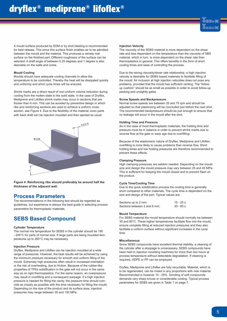
Shrink marks are a direct result of non-uniform volume reduction during cooling from the molten state to the solid state. In the case of Dryfl ex, Mediprene and Lifofl ex shrink marks may occur in sections that are thicker than 6 mm. This can be avoided by preventive design in which ribs and reinforcing sections are used to achieve a uniform cross-section, see Figure 4. Due to the fl exibility of the material, even parts with back draft can be injection moulded and then ejected as usual.
Figure 4. Reinforcing ribs should preferably be around half the thickness of the adjacent wall.
Process ParametersThe recommendations in the following text should be regarded as guidelines, but experience is always the best guide in selecting process parameters for thermoplastic materials.
SEBS Based CompoundCylinder TemperatureThe normal mix temperature for SEBS in the cylinder should be 190 - 245°C for parts of normal size. If large parts are being moulded tem-peratures up to 260°C may be necessary.
Injection PressureDryfl ex, Mediprene and Lifofl ex can be injection moulded at a wide range of pressures. However, the best results will be achieved by using the minimum pressure necessary for smooth and uniform fi lling of the mould. Extremely high pressures often result in increased orientation or the risk of overheating, due to friction. Because of the rubber-like properties of TPEs solidifi cation in the gate will not occur in the same way as on rigid thermoplastics. For the same reason, an overpressure may result in overfi lling and a consequent warpage. If a high injection pressure is needed for fi lling the cavity, the pressure time should coin-cide as closely as possible with the time necessary for fi lling the mould. Depending on the size of the product and its surface area, injection pressures may range between 35 and 150 MPa.
5

SBS Based CompoundCylinder TemperatureThe cylinder temperature for SBS should be between 150 and 205°C, but should not exceed 220°C.
Injection PressureDryfl ex, Mediprene and Lifofl ex can be injection moulded at a wide range of pressures. However, the best results will be achieved by using the minimum pressure, which is necessary for smooth and uniform fi lling of the mould. Excessively high pressures often result in increased orientation or in the risk of overheating, due to friction. Because of the rubber-like properties of TPE solidifi cation in the gate will not occur in the same way as on rigid thermoplastics and overpressure may result in overfi lling and consequent warpage. If a high injection pressure is needed for fi lling the cavity the pressure time should coincide as closely as possible with the time necessary for fi lling the mould. Depending on the size of product and its surface area injection pressures may range between 35 and 150 MPa.
Injection VelocitySBS compounds should preferably be injected at moderate injection velocities. This since they do not demand shear rates that are as high as for SEBS compounds, for achieving low viscosity and good fl ow properties.
Screw Speeds and BackpressureNormal screw speeds are within the range of 25 - 75 rpm and should be adjusted so that plasticizing is concluded just before the next shot. A backpressure, which is just high enough to ensure that no leakage will occur in the mould after the shot, is recommended.
Holding Time and PressureAs in the case of most thermoplastic materials, the holding time and pressure must be in balance in order to prevent shrink marks due to reverse fl ow at the gate or warpage due to overfi lling. Because of the elastomeric nature of TPE, overfi lling is more likely to cause problems than reverse fl ow. Short holding times and low holding pressures are therefore recommended.
Clamping PressureHigh clamping pressures are seldom needed. Depending on the mould size and design, the mould pressure may vary between 25 and 45 MPa. This is suffi cient for keeping the mould closed and preventing fl ash on the product.
Cycle Time/Cooling TimeDue to the quick solidifi cation process when using Dryfl ex, Mediprene and Lifofl ex, the cooling time is generally short compared to other materials. The cycle time is dependent on the size and design of the part. Typical values are:
Sections up to 2 mm: 15 - 25 sSections between 2 and 6 mm: 30 - 60 s
Mould TemperatureThe optimum mould temperatures for SBS based materials are between 20 and 40°C.
MiscellaneousThe SBS compound is sensitive to thermo-oxidative degradation and should not be maintained at high process temperatures for extended periods of time. If cleaning is required, HDPE or PP can be used.
Our TPEs are fully recyclable. Material, which is to be regenerated, can be mixed in any proportions with new material. 10 - 25% is however recommended. Grinding of soft compounds requires very sharp knives or considerable cooling. Typical process parameters are given in Table 1 on page 7.
6

Processparameter Unit SBS SEBS
Machine size (clamping force in tonnes) 90 90Max. shot weight 115 115Mould type 2-part 2-partNumber of cavities 1 1Shot weight
g
g 55 55
Cylinder temperature ºC Rear ºC 170 180 Centre ºC 180 190 Front ºC 190 200 Nozzle ºC 200 210
Mould temperature ºC 25 50
Injection pressure High MPa 50 50 Low MPa 35 50
Injection time s 3-5 1-2Injection rate moderate fastHolding time s 2.5 2.5Clamping time s 10 7Screw speed Rpm 30 40Back pressure MPa 0.55 0.7Cycle time s 20 14
7
Table 1. Typical process parameters for injection moulding of Dryfl ex, Mediprene and Lifofl ex thermoplastic elastomers

ExtrusionDryfl ex, Mediprene and Lifofl ex thermoplastic elastomers can easily be extruded, provided that the right process parameters are used. Due to the three-block structure, the fl ow properties (melt viscosity) are relatively insensitive to temperature changes. However, it responds quickly to changes in shear and/or pressure (applies mainly to materials based on SEBS).
The SEBS compounds, with their saturated intermediate blocks, are very stable against thermal degradation. On the other hand, the SBS compounds degrade if they are overheated or if a screw with excessively high compression ratio is used.
SEBS Based CompoundsLong extruders with a length/diameter (L/D) ratio of 20:1 or more are preferable and long feed zones that are normally employed in the extrusion of polyolefi nes are best for this type of compound. The fl ow paths of the dies should be as short as possible in order to prevent the occurrence of rough surfaces that may arise due to the material solidifi cation process. Long die adapters should be avoided and important is also that both the die and the die adapter should be equipped with heater elements.
The form giving part of the die should be only suffi ciently long to provide the required surface fi nish and product profi le. A form giving part, which is longer than around one cross section or one diameter, may result in surface roughness if followup drawing is used for achieving the required cross section. Although, appreciable follow-up drawing from a long form giving part of the die should be avoided, since minor follow-up drawing (10 - 20%) may result in increased strength of the product.
The melt temperatures in the extrusion of SEBS materials are normally 150 - 210°C, but due to the unique saturated olefi n intermediate block, process temperatures of up to 260°C are permissible. A temperature profi le from the feed zone to the die of 170, 180, 190, 200 and 210°C is suitable as initial setting, and can therefore be adjusted to suit the SEBS grade used and the type of screw. (Lower temperature for the softer compounds.)
Preheating of Dryfl ex, Mediprene and Lifofl ex SEBS compound has proved to result in higher production output. SEBS compounds are easy to process and offer benefi ts such as high thermal stability, resistance to degradation caused by shear and friction and fast solidifi cation of melts.
Screw DesignSEBS based Dryfl ex, Mediprene and Lifofl ex materials are best extruded using screws that have a high compression ratio (3:1) and long, fairly shallow feed zones. Screws with short feed zones may give rise to infeed problems. Screws with compression ratios of 3.0 - 4.5 are normally preferable. As mentioned earlier, the L/D ratio should be at least 20:1. The softer SEBS compounds generally give a lower output at increased backpressure. The frictional heat is lowest on the softer grades and increases substantially on harder grades.
Mixing screws or screws with mixing zones are not necessary for achieving a homogeneous melt. However, such screws may contribute towards an improvement in extruders with shorter L/D ratios than those mentioned above. Some typical screw confi gurations for using SEBS materials are given in table 2.
Other EquipmentThe most common calibration and take-up units for PP and PVC are also suitable for Dryfl ex, Mediprene and Lifofl ex based on SEBS. Recalibration is usually unnecessary for the softer grades (SEBS).
In sheet extrusion, the temperatures of the cooling and polishing rolls should be between 60°C and 80°C. Clean and bright polished rolls and roll temperature control are necessary for minimizing sticking to the rolls, which may sometimes occur on the softer SEBS compounds.
The size of extruded SEBS products can be adjusted by follow-up drawing/follow-up stretching, and this also enables the properties to be modifi ed.
Production CapacityThe extruder capacity is effected by many factors, such as screw design, available motor power, melt temperature, backpressure and heat available. SEBS based materials have extrusion rates comparable to other thermoplastics. The production rate for SEBS based materials tends to be lower for the soft, rubber-like types but the rate increases within increasing hardness and rigidity.
8

Parameters Single Two-stageLength/Diameter (L/D) 24:1 24:1
SECTION 1
Infeed zone
Thread depth (mm) 12.5 13.8
Number of threads 9 6
Compression zone
Number of threads 7 4
Melt zone
Thread depth (mm) 3.6 3.0
Number of threads 8 4
Compression ratio 3.5:1 4.5:1
SECTION 2
Infeed zone
Thread depth (mm) - 14.6
Number of threads - 4
Compression zone
Number of threads - 1.5
Melt zone
Thread depth (mm) - 4.2
Number of threads - 4.4
Compression ratio - 3.5:1
Table 2. Typical screw confi gurations for extruding SEBS based Dryfl ex, Mediprene and Lifofl ex materials (3.5” or approximately 90 mm screw).
9

SBS Based CompoundsSBS based Dryfl ex, Mediprene and Lifofl ex can be extruded in virtually all types of extruders for thermoplastics. Tapered and polished dies produce the best results. Since SBS compounds display less swelling than polyolefi nes, the length of the form-giving part of the die is less critical.
The melt temperatures of SBS compounds in extrusion are between 150 and 205°C, and should not exceed 205°C. A temperature profi le along the extruder cylinders, from 150°C at the infeed zone to 205°C at the die, gives the highest output. A reverse temperature profi le can be employed if a high degree of homogeneity of the melt is to be achieved or if heavy vibrations should occur. This will give a lower output. Due to the unsaturated intermediate block in Dryfl ex, Mediprene and Lifofl ex SBS compounds, extrusion at high temperatures and/or high shear may result in degradation. A reduction in strength may occur due to molecular splitting, depending on the extent of the degradation. Degradation of SBS compounds produces only material with a lower molecular weight, which is not toxic.
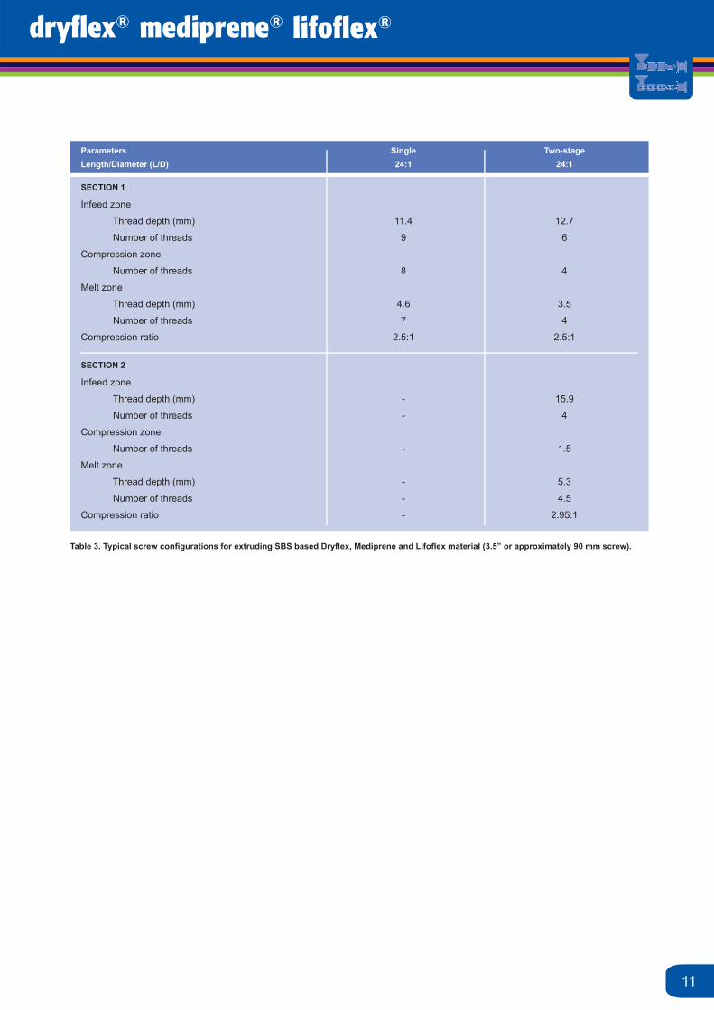
Screw DesignIn the recommended design of the screw, the compression ratio should be low, the melt sections should be fairly deeply threaded and the length/diameter ratio should be >20:1. In table 3, typical screw confi gurations for extruding SBS compounds are shown.
Dryfl ex, Mediprene and Lifofl ex SBS compounds can display solidifi cation tendencies if there are long fl ow paths after the melt has left the shear area in the screw. This solidifi cation, which may result in surface irregularities, occurs due to partially physical cross-linking taking place between the end blocks when the melt enters areas with low shear. This solidifi cation may occur if die heating is far from the screw tip due to a long die adapter.
Other EquipmentFollow-up equipment (calibration and take up units) used for conventional thermoplastics can also be employed for Dryfl ex, Mediprene and Lifofl ex SBS based TPE. When fi lm or sheet is extruded, the polishing roll temperature should be 65 - 80°C in order to minimize sticking.
Due to the rubber like, fl exible nature of many SBS compounds, orientation effects may sometimes occur. Since orientation is a result of stretching appreciable follow-up stretching should be avoided, especially at low extrusion temperatures.
Production RatesDryfl ex, Mediprene and Lifofl ex SBS compounds usually yield higher outputs than the value expected on the basis of the screw design. This is due to the high coeffi cient of friction of these materials on metal. For a given extruder size, the relationship between output and screw speed is linear. A 3.5” extruder can produce 90kg/h at 30 rpm and around 220 kg/h at 70 rpm.
10
Parameters Single Two-stageLength/Diameter (L/D) 24:1 24:1
SECTION 1
Infeed zone
Thread depth (mm) 11.4 12.7
Number of threads 9 6
Compression zone
Number of threads 8 4
Melt zone
Thread depth (mm) 4.6 3.5
Number of threads 7 4
Compression ratio 2.5:1 2.5:1
SECTION 2
Infeed zone
Thread depth (mm) - 15.9
Number of threads - 4
Compression zone
Number of threads - 1.5
Melt zone
Thread depth (mm) - 5.3
Number of threads - 4.5
Compression ratio - 2.95:1
Table 3. Typical screw confi gurations for extruding SBS based Dryfl ex, Mediprene and Lifofl ex material (3.5” or approximately 90 mm screw).
11
UK_EMK_v1
Contact us...
UKt : +44 161 654 6616f : +44 161 654 [email protected]
Swedent : +46 532 60 75 00f : +46 532 60 75 [email protected]
Chinat : +86 757 2291 5100f : +86 757 2291 [email protected]
Francet : +33 160 43 17 17f : +33 160 43 11 [email protected]
Germanyt : +49 9571 94894 0f : +49 9571 94894 [email protected]
About us...ELASTO and Müller Kunststoffe deliver a winning line-up in TPE and complimentary compounds. With a strong heritage in our home markets, we have a trusted reputation for technical, custom formulated solutions. We were among the fi rst companies to start producing TPE compounds in Europe and have continually invested in people, production and technology; to expand capacity and support our growing global customer base.
A comprehensive product portfolio covering TPS (SBS, SEBS and SEPS), TPO, TPV, TPU, soft PVC, cork compounds and masterbatch is led by global brands Dryfl ex®, Mediprene®, Lifofl ex®, Lifoprene®, Lifolit®, Lifocork® and Lifobatch®. We support OEMs, moulders and designers at all stages of product development in the medical, electronic, automotive, construction and consumer markets.
Mediprene®, Dryfl ex®, Lifoprene®, Lifofl ex®, Lifocork®, Lifolit® and Lifobatch® are registered trademarks property of the HEXPOL group of companies.
For further information or to download this and other publications please visit
www.elastotpe.com or www.mueller-kunststoffe.com