Embed Size (px)
Citation preview
ETSI TR 137 901 V14.0.0 (2018-04)
Universal Mobile Telecommunications System (UMTS); LTE;
User Equipment (UE) application layer data throughput performance
(3GPP TR 37.901 version 14.0.0 Release 14)
TECHNICAL REPORT
ETSI
ETSI TR 137 901 V14.0.0 (2018-04)13GPP TR 37.901 version 14.0.0 Release 14
Reference RTR/TSGR-0537901ve00
Keywords LTE,UMTS
ETSI
650 Route des Lucioles F-06921 Sophia Antipolis Cedex - FRANCE
Tel.: +33 4 92 94 42 00 Fax: +33 4 93 65 47 16
Siret N° 348 623 562 00017 - NAF 742 C
Association à but non lucratif enregistrée à la Sous-Préfecture de Grasse (06) N° 7803/88
Important notice
The present document can be downloaded from: http://www.etsi.org/standards-search
The present document may be made available in electronic versions and/or in print. The content of any electronic and/or print versions of the present document shall not be modified without the prior written authorization of ETSI. In case of any
existing or perceived difference in contents between such versions and/or in print, the only prevailing document is the print of the Portable Document Format (PDF) version kept on a specific network drive within ETSI Secretariat.
Users of the present document should be aware that the document may be subject to revision or change of status. Information on the current status of this and other ETSI documents is available at
https://portal.etsi.org/TB/ETSIDeliverableStatus.aspx
If you find errors in the present document, please send your comment to one of the following services: https://portal.etsi.org/People/CommiteeSupportStaff.aspx
Copyright Notification
No part may be reproduced or utilized in any form or by any means, electronic or mechanical, including photocopying and microfilm except as authorized by written permission of ETSI.
The content of the PDF version shall not be modified without the written authorization of ETSI. The copyright and the foregoing restriction extend to reproduction in all media.
© ETSI 2018.
All rights reserved.
DECTTM, PLUGTESTSTM, UMTSTM and the ETSI logo are trademarks of ETSI registered for the benefit of its Members. 3GPPTM and LTETM are trademarks of ETSI registered for the benefit of its Members and
of the 3GPP Organizational Partners. oneM2M logo is protected for the benefit of its Members.
GSM® and the GSM logo are trademarks registered and owned by the GSM Association.
ETSI
ETSI TR 137 901 V14.0.0 (2018-04)23GPP TR 37.901 version 14.0.0 Release 14
Intellectual Property Rights
Essential patents
IPRs essential or potentially essential to normative deliverables may have been declared to ETSI. The information pertaining to these essential IPRs, if any, is publicly available for ETSI members and non-members, and can be found in ETSI SR 000 314: "Intellectual Property Rights (IPRs); Essential, or potentially Essential, IPRs notified to ETSI in respect of ETSI standards", which is available from the ETSI Secretariat. Latest updates are available on the ETSI Web server (https://ipr.etsi.org/).
Pursuant to the ETSI IPR Policy, no investigation, including IPR searches, has been carried out by ETSI. No guarantee can be given as to the existence of other IPRs not referenced in ETSI SR 000 314 (or the updates on the ETSI Web server) which are, or may be, or may become, essential to the present document.
Trademarks
The present document may include trademarks and/or tradenames which are asserted and/or registered by their owners. ETSI claims no ownership of these except for any which are indicated as being the property of ETSI, and conveys no right to use or reproduce any trademark and/or tradename. Mention of those trademarks in the present document does not constitute an endorsement by ETSI of products, services or organizations associated with those trademarks.
Foreword This Technical Report (TR) has been produced by ETSI 3rd Generation Partnership Project (3GPP).
The present document may refer to technical specifications or reports using their 3GPP identities, UMTS identities or GSM identities. These should be interpreted as being references to the corresponding ETSI deliverables.
The cross reference between GSM, UMTS, 3GPP and ETSI identities can be found under http://webapp.etsi.org/key/queryform.asp.
Modal verbs terminology In the present document "should", "should not", "may", "need not", "will", "will not", "can" and "cannot" are to be interpreted as described in clause 3.2 of the ETSI Drafting Rules (Verbal forms for the expression of provisions).
"must" and "must not" are NOT allowed in ETSI deliverables except when used in direct citation.
ETSI
ETSI TR 137 901 V14.0.0 (2018-04)33GPP TR 37.901 version 14.0.0 Release 14
Contents
Intellectual Property Rights ................................................................................................................................ 2
Foreword ............................................................................................................................................................. 2
Modal verbs terminology .................................................................................................................................... 2
Foreword ........................................................................................................................................................... 10
1 Scope ...................................................................................................................................................... 11
2 References .............................................................................................................................................. 11
3 Definitions, symbols and abbreviations ................................................................................................. 12
3.1 Definitions ........................................................................................................................................................ 12
3.2 Symbols ............................................................................................................................................................ 12
3.3 Abbreviations ................................................................................................................................................... 12
4 Background ............................................................................................................................................ 14
4.1 Study Item Objective ........................................................................................................................................ 14
5 Study of UE Application Layer Data Throughput Performance ............................................................ 15
5.1 Definition of UE Application Layer Data Throughput Performance ............................................................... 15
5.1.1 Definition of End Points ............................................................................................................................. 15
5.1.2 Definition of UE Application Layer Data Throughput ............................................................................... 15
5.2 Parameters for Measurement ............................................................................................................................ 15
5.2.1 Throughput ................................................................................................................................................. 15
5.3 Test Configurations .......................................................................................................................................... 16
5.3.1 UE Application Layer Data Throughput Test Equipment .......................................................................... 16
5.3.2 UE Application Layer Data Throughput Connection Diagrams ................................................................. 16
5.3.2.1 UE Application Layer Data Throughput Connection Diagram for Tethered ........................................ 16
5.3.2.2 UE Application Layer Data Throughput Connection Diagram for Embedded ..................................... 16
5.3.3 RF Connection Diagrams for UE Application Layer Data Throughput ..................................................... 16
5.3.4 UE Specific Items ....................................................................................................................................... 16
5.3.5 Reference Laptop ........................................................................................................................................ 16
5.4 Transport and Application Layer Protocols ...................................................................................................... 17
5.4.1 Transport Layer Protocol ............................................................................................................................ 17
5.4.2 Application Layer Protocol ......................................................................................................................... 17
5.4.2.1 FTP Settings .......................................................................................................................................... 18
5.4.2.1.1 TCP advertised receiver window size setting .................................................................................. 19
5.4.2.2 UDP Settings ......................................................................................................................................... 19
5.5 Test Environment ............................................................................................................................................. 20
5.5.1 Signal Levels .............................................................................................................................................. 20
5.5.2 Fading Profiles ............................................................................................................................................ 20
5.5.3 Noise and Interference Levels .................................................................................................................... 21
5.5.4 Selection of combinations of Fading Profiles and Noise and Interference Levels ...................................... 21
5.5.4.1 General .................................................................................................................................................. 21
5.5.4.2 Lower-layer (PHY) testing .................................................................................................................... 21
5.5.4.3 Higher-layer impact on application layer throughput ........................................................................... 22
5.5.4.4 Typical physical parameters for verifying higher-layer impact ............................................................ 23
5.5.4.5 Selection of test points .......................................................................................................................... 25
5.5.5 Traffic Profiles ............................................................................................................................................ 26
5.6 Data Transfer Scenarios ................................................................................................................................... 27
5.6.1 FTP Transfers ............................................................................................................................................. 27
5.6.2 UDP Transfers ............................................................................................................................................ 27
5.7 Statistical Analysis ........................................................................................................................................... 27
5.7.1 Layer 1 Receiver and Performance Tests ................................................................................................... 27
5.7.2 Application Layer Data Throughput ........................................................................................................... 27
5.7.3 Minimum Test Time ................................................................................................................................... 28
5.8 Impact of Modem Performance in Application Layer Throughput .................................................................. 28
5.8.1 Modem Performance in current TS 34.121-1/TS 34.122 Conformance Tests ............................................ 29
5.8.2 Modem Performance in Application Layer Data Throughput Tests ........................................................... 32
ETSI
ETSI TR 137 901 V14.0.0 (2018-04)43GPP TR 37.901 version 14.0.0 Release 14
5.9 Test System Uncertainty and Test Tolerance ................................................................................................... 34
5.9.1 Recommended Uncertainty of Test System ................................................................................................ 34
5.9.2 Test Tolerances ........................................................................................................................................... 34
5.9.3 Impact of Test System Uncertainty on Test Results ................................................................................... 34
6 Conclusions ............................................................................................................................................ 38
Annex A: Test Procedures .............................................................................................. 40
A.1 Purpose of annex .................................................................................................................................... 40
A.2 UE Application Layer Data Throughput Performance Test Procedures for HSPA ............................... 40
A.2.1 General ............................................................................................................................................................. 40
A.2.2 HSPA / FTP Downlink Performance................................................................................................................ 41
A.2.2.1 Definition .................................................................................................................................................... 41
A.2.2.2 Test Purpose................................................................................................................................................ 42
A.2.2.3 Test Parameters ........................................................................................................................................... 42
A.2.2.4 Test Description .......................................................................................................................................... 42
A.2.2.4.1 Initial Conditions ................................................................................................................................... 42
A.2.2.4.2 Procedure .............................................................................................................................................. 43
A.2.3 HSPA / UDP Downlink Performance .............................................................................................................. 43
A.2.3.1 Definition .................................................................................................................................................... 43
A.2.3.2 Test Purpose................................................................................................................................................ 43
A.2.3.3 Test Parameters ........................................................................................................................................... 43
A.2.3.4 Test Description .......................................................................................................................................... 44
A.2.3.4.1 Initial Conditions ................................................................................................................................... 44
A.2.3.4.2 Procedure .............................................................................................................................................. 45
A.2.4 HSPA / FTP Uplink Performance .................................................................................................................... 45
A.2.4.1 Definition .................................................................................................................................................... 45
A.2.4.2 Test Purpose................................................................................................................................................ 45
A.2.4.3 Test Parameters ........................................................................................................................................... 45
A.2.4.4 Test Description .......................................................................................................................................... 46
A.2.4.4.1 Initial Conditions ................................................................................................................................... 46
A.2.4.4.2 Procedure .............................................................................................................................................. 46
A.2.5 HSPA / UDP Uplink Performance ................................................................................................................... 47
A.2.5.1 Definition .................................................................................................................................................... 47
A.2.5.2 Test Purpose................................................................................................................................................ 47
A.2.5.3 Test Parameters ........................................................................................................................................... 47
A.2.5.4 Test Description .......................................................................................................................................... 48
A.2.5.4.1 Initial Conditions ................................................................................................................................... 48
A.2.5.4.2 Procedure .............................................................................................................................................. 48
A.2.6 HSPA / Stress Test Performance ...................................................................................................................... 49
A.2.6.1 Definition .................................................................................................................................................... 49
A.2.6.2 Test Purpose................................................................................................................................................ 49
A.2.6.3 Test Parameters ........................................................................................................................................... 49
A.2.6.4 Test Description .......................................................................................................................................... 50
A.2.6.4.1 Initial Conditions ................................................................................................................................... 50
A.2.6.4.2 Procedure .............................................................................................................................................. 50
A.2.7 HSPA / UDP Power Sweep Performance ......................................................................................................... 50
A.2.7.1 Definition .................................................................................................................................................... 50
A.2.7.2 Test Purpose................................................................................................................................................ 50
A.2.7.3 Test Parameters ........................................................................................................................................... 51
A.2.7.4 Test Description .......................................................................................................................................... 51
A.2.7.4.1 Initial Conditions ................................................................................................................................... 51
A.2.7.4.2 Procedure .............................................................................................................................................. 52
A.2.8 HSPA / Throughput vs. Geometry Factor Performance ................................................................................... 52
A.2.8.1 Definition .................................................................................................................................................... 52
A.2.8.2 Test Purpose................................................................................................................................................ 52
A.2.8.3 Test Parameters ........................................................................................................................................... 52
A.2.8.4 Test Description .......................................................................................................................................... 53
A.2.8.4.1 Initial Conditions ................................................................................................................................... 53
A.2.8.4.2 Procedure .............................................................................................................................................. 53
ETSI
ETSI TR 137 901 V14.0.0 (2018-04)53GPP TR 37.901 version 14.0.0 Release 14
A.3 UE Application Layer Data Throughput Performance Test Procedures for LTE .................................. 54
A.3.1 General ............................................................................................................................................................. 54
A.3.2 LTE / FTP Downlink Performance .................................................................................................................. 58
A.3.2.1 LTE / FTP Downlink / PDSCH Single Antenna Port Performance (Cell-Specific Reference Symbols) ..................................................................................................................................................... 58
A.3.2.1.1 Definition .............................................................................................................................................. 58
A.3.2.1.2 Test Purpose .......................................................................................................................................... 58
A.3.2.1.3 Test Parameters ..................................................................................................................................... 58
A.3.2.1.4 Test Description .................................................................................................................................... 59
A.3.2.1.4.1 Initial Conditions ............................................................................................................................. 59
A.3.2.1.4.2 Procedure ......................................................................................................................................... 59
A.3.2.2 LTE / FTP Downlink / PDSCH Transmit Diversity Performance (Cell-Specific Reference Symbols) ..... 60
A.3.2.2.1 Definition .............................................................................................................................................. 60
A.3.2.2.2 Test Purpose .......................................................................................................................................... 60
A.3.2.2.3 Test Parameters ..................................................................................................................................... 60
A.3.2.2.4 Test Description .................................................................................................................................... 61
A.3.2.2.4.1 Initial Conditions ............................................................................................................................. 61
A.3.2.2.4.2 Procedure ......................................................................................................................................... 61
A.3.2.3 LTE / FTP Downlink / PDSCH Open Loop Spatial Multiplexing Performance (Cell-Specific Reference Symbols) .................................................................................................................................... 62
A.3.2.3.1 Definition .............................................................................................................................................. 62
A.3.2.3.2 Test Purpose .......................................................................................................................................... 62
A.3.2.3.3 Test Parameters ..................................................................................................................................... 62
A.3.2.3.4 Test Description .................................................................................................................................... 63
A.3.2.3.4.1 Initial Conditions ............................................................................................................................. 63
A.3.2.3.4.2 Procedure ......................................................................................................................................... 63
A.3.2.4 LTE / FTP Downlink / PDSCH Closed Loop Spatial Multiplexing Performance (Cell-Specific Reference Symbols) .................................................................................................................................... 64
A.3.2.4.1 Definition .............................................................................................................................................. 64
A.3.2.4.2 Test Purpose .......................................................................................................................................... 64
A.3.2.4.3 Test Parameters ..................................................................................................................................... 64
A.3.2.4.4 Test Description .................................................................................................................................... 66
A.3.2.4.4.1 Initial Conditions ............................................................................................................................. 66
A.3.2.4.4.2 Procedure ......................................................................................................................................... 66
A.3.2.5 LTE / FTP Downlink / PDSCH Single-layer Spatial Multiplexing Performance (Port 5, UE-Specific Reference Symbols) .................................................................................................................................... 66
A.3.2.5.1 Definition .............................................................................................................................................. 66
A.3.2.5.2 Test Purpose .......................................................................................................................................... 67
A.3.2.5.3 Test Parameters ..................................................................................................................................... 67
A.3.2.5.4 Test Description .................................................................................................................................... 68
A.3.2.5.4.1 Initial Conditions ............................................................................................................................. 68
A.3.2.5.4.2 Procedure ......................................................................................................................................... 68
A.3.2.6 LTE / FTP Downlink / PDSCH Single-layer Spatial Multiplexing Performance (Port 7 or 8, UE-Specific Reference Symbols) ...................................................................................................................... 68
A.3.2.6.1 Definition .............................................................................................................................................. 68
A.3.2.6.2 Test Purpose .......................................................................................................................................... 69
A.3.2.6.3 Test Parameters ..................................................................................................................................... 69
A.3.2.6.4 Test Description .................................................................................................................................... 70
A.3.2.6.4.1 Initial Conditions ............................................................................................................................. 70
A.3.2.6.4.2 Procedure ......................................................................................................................................... 70
A.3.2.7 LTE / FTP Downlink / PDSCH Dual-layer Spatial Multiplexing Performance (port 7 and 8, User-Specific Reference Symbols) ...................................................................................................................... 71
A.3.2.7.1 Definition .............................................................................................................................................. 71
A.3.2.7.2 Test Purpose .......................................................................................................................................... 71
A.3.2.7.3 Test Parameters ..................................................................................................................................... 71
A.3.2.7.4 Test Description .................................................................................................................................... 73
A.3.2.7.4.1 Initial Conditions ............................................................................................................................. 73
A.3.2.7.4.2 Procedure ......................................................................................................................................... 73
A.3.3 LTE / UDP Downlink Performance ................................................................................................................. 73
A.3.3.1 LTE / UDP Downlink / PDSCH Single Antenna Port Performance (Cell-Specific Reference Symbols) ..................................................................................................................................................... 73
A.3.3.1.1 Definition .............................................................................................................................................. 73
ETSI
ETSI TR 137 901 V14.0.0 (2018-04)63GPP TR 37.901 version 14.0.0 Release 14
A.3.3.1.2 Test Purpose .......................................................................................................................................... 74
A.3.3.1.3 Test Parameters ..................................................................................................................................... 74
A.3.3.1.4 Test Description .................................................................................................................................... 75
A.3.3.1.4.1 Initial Conditions ............................................................................................................................. 75
A.3.3.1.4.2 Procedure ......................................................................................................................................... 75
A.3.3.2 LTE / UDP Downlink / PDSCH Transmit Diversity Performance (Cell-Specific Reference Symbols) .... 75
A.3.3.2.1 Definition .............................................................................................................................................. 75
A.3.3.2.2 Test Purpose .......................................................................................................................................... 76
A.3.3.2.3 Test Parameters ..................................................................................................................................... 76
A.3.3.2.4 Test Description .................................................................................................................................... 77
A.3.3.2.4.1 Initial Conditions ............................................................................................................................. 77
A.3.3.2.4.2 Procedure ......................................................................................................................................... 77
A.3.3.3 LTE / UDP Downlink / PDSCH Open Loop Spatial Multiplexing Performance (Cell-Specific Reference Symbols) .................................................................................................................................... 77
A.3.3.3.1 Definition .............................................................................................................................................. 77
A.3.3.3.2 Test Purpose .......................................................................................................................................... 78
A.3.3.3.3 Test Parameters ..................................................................................................................................... 78
A.3.3.3.4 Test Description .................................................................................................................................... 79
A.3.3.3.4.1 Initial Conditions ............................................................................................................................. 79
A.3.3.3.4.2 Procedure ......................................................................................................................................... 79
A.3.3.4 LTE / UDP Downlink / PDSCH Closed Loop Spatial Multiplexing Performance (Cell-Specific Reference Symbols) .................................................................................................................................... 80
A.3.3.4.1 Definition .............................................................................................................................................. 80
A.3.3.4.2 Test Purpose .......................................................................................................................................... 80
A.3.3.4.3 Test Parameters ..................................................................................................................................... 80
A.3.3.4.4 Test Description .................................................................................................................................... 82
A.3.3.4.4.1 Initial Conditions ............................................................................................................................. 82
A.3.3.4.4.2 Procedure ......................................................................................................................................... 82
A.3.3.5 LTE / UDP Downlink / PDSCH Single-layer Spatial Multiplexing Performance (port 5, User-Specific Reference Symbols) ...................................................................................................................... 82
A.3.3.5.1 Definition .............................................................................................................................................. 82
A.3.3.5.2 Test Purpose .......................................................................................................................................... 83
A.3.3.5.3 Test Parameters ..................................................................................................................................... 83
A.3.3.5.4 Test Description .................................................................................................................................... 84
A.3.3.5.4.1 Initial Conditions ............................................................................................................................. 84
A.3.3.5.4.2 Procedure ......................................................................................................................................... 84
A.3.3.6 LTE / UDP Downlink / PDSCH Single-layer Spatial Multiplexing Performance (Port 7 or 8, UE-Specific Reference Symbols) ...................................................................................................................... 84
A.3.3.6.1 Definition .............................................................................................................................................. 84
A.3.3.6.2 Test Purpose .......................................................................................................................................... 85
A.3.3.6.3 Test Parameters ..................................................................................................................................... 85
A.3.3.6.4 Test Description .................................................................................................................................... 86
A.3.3.6.4.1 Initial Conditions ............................................................................................................................. 86
A.3.3.6.4.2 Procedure ......................................................................................................................................... 86
A.3.3.7 LTE / UDP Downlink / PDSCH Dual-layer Spatial Multiplexing Performance (port 7 and 8, User-Specific Reference Symbols) ...................................................................................................................... 87
A.3.3.7.1 Definition .............................................................................................................................................. 87
A.3.3.7.2 Test Purpose .......................................................................................................................................... 87
A.3.3.7.3 Test Parameters ..................................................................................................................................... 87
A.3.3.7.4 Test Description .................................................................................................................................... 89
A.3.3.7.4.1 Initial Conditions ............................................................................................................................. 89
A.3.3.7.4.2 Procedure ......................................................................................................................................... 89
A.3.4 LTE / FTP Uplink Performance ....................................................................................................................... 89
A.3.4.1 LTE / FTP Uplink / PUSCH Single Antenna Port Performance ................................................................. 89
A.3.4.1.1 Definition .............................................................................................................................................. 89
A.3.4.1.2 Test Purpose .......................................................................................................................................... 90
A.3.4.1.3 Test Parameters ..................................................................................................................................... 90
A.3.4.1.4 Test Description .................................................................................................................................... 90
A.3.4.1.4.1 Initial Conditions ............................................................................................................................. 90
A.3.4.1.4.2 Procedure ......................................................................................................................................... 90
A.3.5 LTE / UDP Uplink Performance ...................................................................................................................... 91
A.3.5.1 LTE / UDP Uplink / PUSCH Single Antenna Port Performance ............................................................... 91
ETSI
ETSI TR 137 901 V14.0.0 (2018-04)73GPP TR 37.901 version 14.0.0 Release 14
A.3.5.1.1 Definition .............................................................................................................................................. 91
A.3.5.1.2 Test Purpose .......................................................................................................................................... 91
A.3.5.1.3 Test Parameters ..................................................................................................................................... 91
A.3.5.1.4 Test Description .................................................................................................................................... 91
A.3.5.1.4.1 Initial Conditions ............................................................................................................................. 91
A.3.5.1.4.2 Procedure ......................................................................................................................................... 92
A.3.6 LTE / Stress Test Performance ......................................................................................................................... 92
A.3.6.1 LTE / Stress Test Performance / PDSCH Transmit Diversity Performance (Cell-Specific Reference Symbols) ..................................................................................................................................................... 92
A.3.6.1.1 Definition .............................................................................................................................................. 92
A.3.6.1.2 Test Purpose .......................................................................................................................................... 93
A.3.6.1.3 Test Parameters ..................................................................................................................................... 93
A.3.6.1.4 Test Description .................................................................................................................................... 94
A.3.6.1.4.1 Initial Conditions ............................................................................................................................. 94
A.3.6.1.4.2 Procedure ......................................................................................................................................... 94
A.3.6.2 LTE / Stress Test Performance / PDSCH Open Loop Spatial Multiplexing Performance (Cell-Specific Reference Symbols) ...................................................................................................................... 94
A.3.6.2.1 Definition .............................................................................................................................................. 94
A.3.6.2.2 Test Purpose .......................................................................................................................................... 94
A.3.6.2.3 Test Parameters ..................................................................................................................................... 95
A.3.6.2.4 Test Description .................................................................................................................................... 95
A.3.6.2.4.1 Initial Conditions ............................................................................................................................. 95
A.3.6.2.4.2 Procedure ......................................................................................................................................... 96
A.3.7 LTE / UDP Power Sweep Performance ........................................................................................................... 96
A.3.7.1 LTE / UDP Power Sweep Performance / PDSCH Transmit Diversity Performance (Cell-Specific Reference Symbols) .................................................................................................................................... 96
A.3.7.1.1 Definition .............................................................................................................................................. 96
A.3.7.1.2 Test Purpose .......................................................................................................................................... 96
A.3.7.1.3 Test Parameters ..................................................................................................................................... 97
A.3.7.1.4 Test Description .................................................................................................................................... 98
A.3.7.1.4.1 Initial Conditions ............................................................................................................................. 98
A.3.7.1.4.2 Procedure ......................................................................................................................................... 98
A.3.7.2 LTE / UDP Power Sweep Performance / PDSCH Open Loop Spatial Multiplexing Performance (Cell-Specific Reference Symbols) ............................................................................................................. 99
A.3.7.2.1 Definition .............................................................................................................................................. 99
A.3.7.2.2 Test Purpose .......................................................................................................................................... 99
A.3.7.2.3 Test Parameters ..................................................................................................................................... 99
A.3.7.2.4 Test Description .................................................................................................................................. 100
A.3.7.2.4.1 Initial Conditions ........................................................................................................................... 100
A.3.7.2.4.2 Procedure ....................................................................................................................................... 101
A.3.8 LTE / UDP Downlink vs. SNR Performance ................................................................................................. 101
A.3.8.1 LTE / UDP Downlink vs. SNR Performance / PDSCH Transmit Diversity Performance (Cell-Specific Reference Symbols) .................................................................................................................... 101
A.3.8.1.1 Definition ............................................................................................................................................ 101
A.3.8.1.2 Test Purpose ........................................................................................................................................ 101
A.3.8.1.3 Test Parameters ................................................................................................................................... 101
A.3.8.1.4 Test Description .................................................................................................................................. 102
A.3.8.1.4.1 Initial Conditions ........................................................................................................................... 102
A.3.8.1.4.2 Procedure ....................................................................................................................................... 103
A.3.8.2 LTE / UDP Downlink vs. SNR Performance / PDSCH Open Loop Spatial Multiplexing Performance (Cell-Specific Reference Symbols) ..................................................................................... 103
A.3.8.2.1 Definition ............................................................................................................................................ 103
A.3.8.2.2 Test Purpose ........................................................................................................................................ 103
A.3.8.2.3 Test Parameters ................................................................................................................................... 103
A.3.8.2.4 Test Description .................................................................................................................................. 105
A.3.8.2.4.1 Initial Conditions ........................................................................................................................... 105
A.3.8.2.4.2 Procedure ....................................................................................................................................... 106
A.3.8.3 LTE / UDP Downlink vs. SNR Performance / PDSCH Closed Loop Spatial Multiplexing Performance (Cell-Specific Reference Symbols) ..................................................................................... 106
A.3.8.3.1 Definition ............................................................................................................................................ 106
A.3.8.3.2 Test Purpose ........................................................................................................................................ 106
A.3.8.3.3 Test Parameters ................................................................................................................................... 106
ETSI
ETSI TR 137 901 V14.0.0 (2018-04)83GPP TR 37.901 version 14.0.0 Release 14
A.3.8.3.4 Test Description .................................................................................................................................. 108
A.3.8.3.4.1 Initial Conditions ........................................................................................................................... 108
A.3.8.3.4.2 Procedure ....................................................................................................................................... 109
A.3.8.4 LTE / UDP Downlink vs. SNR Performance / PDSCH Closed Loop Spatial Multiplexing using a single transmission layer Performance (Cell-Specific Reference Symbols) ............................................. 109
A.3.8.4.1 Definition ............................................................................................................................................ 109
A.3.8.4.2 Test Purpose ........................................................................................................................................ 109
A.3.8.4.3 Test Parameters ................................................................................................................................... 109
A.3.8.4.4 Test Description .................................................................................................................................. 110
A.3.8.4.4.1 Initial Conditions ........................................................................................................................... 110
A.3.8.4.4.2 Procedure ....................................................................................................................................... 111
Annex B: Specific Test Conditions and Environment ............................................... 112
B.0 Purpose of Annex ................................................................................................................................. 112
B.1 Reference Test Points ........................................................................................................................... 112
B.1.1 Reference Test Points for HSPA .................................................................................................................... 112
B.1.2 Reference Test Points for LTE ....................................................................................................................... 113
B.2 Reference system configurations .......................................................................................................... 113
B.2.1 HSPA reference system configurations .......................................................................................................... 113
B.2.1.1 Mapping of UE reported CQI and TBS (HSPA) ...................................................................................... 113
B.2.1.2 MAC Configurations ................................................................................................................................ 113
B.2.1.3 RLC Configuration ................................................................................................................................... 113
B.2.1.4 PDCP Configuration ................................................................................................................................. 114
B.2.2 LTE reference system configurations ............................................................................................................. 114
B.2.2.1 Mapping of UE reported CQI and MCS (LTE) ........................................................................................ 114
B.2.2.2 MAC Configurations ................................................................................................................................ 120
B.2.2.3 RLC Configuration ................................................................................................................................... 121
B.2.2.4 PDCP Configuration ................................................................................................................................. 121
B.2.2.5 System Information................................................................................................................................... 121
B.2.2.6 Mapping of UE reported PMI ................................................................................................................... 121
B.2.2.7 Mapping of UE reported RI ...................................................................................................................... 121
B.2.3 Network, Transport and Application Layers reference system configurations............................................... 121
B.2.3.1 FTP Reference System Configuration ...................................................................................................... 121
B.2.3.2 UDP Reference System Configuration ..................................................................................................... 122
B.3 Recommendation for Operating band and Channel Bandwidth selection for application layer data throughput measurements..................................................................................................................... 123
Annex C: Specific Connection Diagrams .................................................................... 124
C.1 Purpose of annex .................................................................................................................................. 124
C.2 UE Application Layer Data Throughput Connection Diagrams .......................................................... 124
C.2.1 UE Application Layer Data Throughput Connection Diagram for Tethered ................................................. 124
C.2.2 UE Application Layer Data Throughput Connection Diagram for Embedded............................................... 124
Annex D: Applicability ................................................................................................. 126
D.1 Purpose of annex ............................................................................................................................................ 126
D.2 Recommended Test Case Applicability ......................................................................................................... 126
D.3 ICS / IXIT proforma ....................................................................................................................................... 133
D.3.1 General ...................................................................................................................................................... 133
D.3.1.1 Introduction ......................................................................................................................................... 133
D.3.1.2 Abbreviations and conventions ........................................................................................................... 133
D.3.1.3 Instructions for completing the ICS proforma..................................................................................... 134
D.3.2 Identification of the protocol .................................................................................................................... 134
D.3.3 ICS proforma tables .................................................................................................................................. 134
D.3.3.1 UE Implementation Types .................................................................................................................. 134
D.3.3.2 UE UTRA related capabilities............................................................................................................. 135
D.3.3.3 UE E-UTRA related capabilities ......................................................................................................... 136
D.3.4 IXIT proforma tables ................................................................................................................................ 137
D.3.4.1 UE data configuration capabilities types ............................................................................................. 137
ETSI
ETSI TR 137 901 V14.0.0 (2018-04)93GPP TR 37.901 version 14.0.0 Release 14
Annex E: Embedded Data Client Automation Recommendations........................... 138
E.1 Purpose of annex .................................................................................................................................. 138
E.2 Embedded Data Client Automation...................................................................................................... 138
E.2.1 Embedded Data Client Functionality ............................................................................................................. 138
E.2.2 Embedded Data Client Provisioning .............................................................................................................. 138
E.2.3 Embedded Data Client Command Set and Operation .................................................................................... 139
E.2.3.1 Poll for Task Command ...................................................................................................................... 139
E.2.3.2 Task List .............................................................................................................................................. 139
E.2.3.3 Result Reporting ................................................................................................................................. 139
Annex F: Measurement Channels ............................................................................... 140
F.1 Purpose of annex .................................................................................................................................. 140
F.2 UL reference measurement channels ................................................................................................... 140
F.2.1 FDD ................................................................................................................................................................ 140
F.2.2 TDD ................................................................................................................................................................ 141
Annex G: Change history ............................................................................................. 142
History ............................................................................................................................................................ 146
ETSI
ETSI TR 137 901 V14.0.0 (2018-04)103GPP TR 37.901 version 14.0.0 Release 14
Foreword This Technical Report has been produced by the 3rd Generation Partnership Project (3GPP).
The contents of the present document are subject to continuing work within the TSG and may change following formal TSG approval. Should the TSG modify the contents of the present document, it will be re-released by the TSG with an identifying change of release date and an increase in version number as follows:
Version x.y.z
where:
x the first digit:
1 presented to TSG for information;
2 presented to TSG for approval;
3 or greater indicates TSG approved document under change control.
y the second digit is incremented for all changes of substance, i.e. technical enhancements, corrections, updates, etc.
z the third digit is incremented when editorial only changes have been incorporated in the document.
ETSI
ETSI TR 137 901 V14.0.0 (2018-04)113GPP TR 37.901 version 14.0.0 Release 14
1 Scope The present document contains the findings of the Study Item on UE Application Layer Data Throughput Performance and the proposed test procedures.
2 References The following documents contain provisions which, through reference in this text, constitute provisions of the present document.
- References are either specific (identified by date of publication, edition number, version number, etc.) or non-specific.
- For a specific reference, subsequent revisions do not apply.
- For a non-specific reference, the latest version applies. In the case of a reference to a 3GPP document (including a GSM document), a non-specific reference implicitly refers to the latest version of that document in the same Release as the present document.
[1] 3GPP TR 21.905: "Vocabulary for 3GPP Specifications".
[2] 3GPP TS 36.521-1: "Evolved Universal Terrestrial Radio Access (E-UTRA); User Equipment (UE) conformance specification Radio transmission and reception Part 1: Conformance Testing".
[3] 3GPP TS 34.121-1: "User Equipment (UE) conformance specification; Radio transmission and reception (FDD); Part 1: Conformance specification".
[4] 3GPP TS 34.122: "Terminal conformance specification; Radio transmission and reception (TDD)".
[5] 3GPP TS 34.123-1: "User Equipment (UE) conformance specification; Part 1: Protocol conformance specification".
[6] 3GPP TS 25.214: "Physical layer procedures (FDD)".
[7] 3GPP TS 25.224: "Physical Layer Procedures (TDD)".
[8] 3GPP TS 33.401: "3GPP System Architecture Evolution (SAE): Security architecture".
[9] 3GPP TS 36.211: "Physical Channels and Modulation".
[10] 3GPP TS 36.213: "E-UTRA Physical layer procedures".
[11] 3GPP TS 36.508: “Common test environments for User Equipment (UE)".
[12] 3GPP TS 25.101: "UE Radio transmission and reception (FDD)".
[13] 3GPP TS 36.101: "E-UTRA UE radio transmission and reception".
[14] 3GPP TS 34.108: "Common Test Environments for User Equipment (UE) Conformance Testing".
[15] L. J. Greenstein, V. Erceg, Y. S. Yeh, and M. V. Clark, “A new path-gain/delay-spread propagation model for digital cellular channels”, IEEE Trans. on Vehicular Technology, Vol. 46, No. 2, May 1997, pp. 477-485.
[16] 3GPP TS 36.306: "E-UTRA User Equipment (UE) radio access capabilities".
[17] 3GPP TS 36.331: “Evolved Universal Terrestrial Radio Access (E-UTRA); Radio Resource Control (RRC); Protocol specification”.
ETSI
ETSI TR 137 901 V14.0.0 (2018-04)123GPP TR 37.901 version 14.0.0 Release 14
3 Definitions, symbols and abbreviations
3.1 Definitions For the purposes of the present document, the terms and definitions given in TR 21.905 [1] and the following apply. A term defined in the present document takes precedence over the definition of the same term, if any, in TR 21.905 [1].
Channel bandwidth: The RF bandwidth supporting a single E-UTRA RF carrier with the transmission bandwidth configured in the uplink or downlink of a cell. The channel bandwidth is measured in MHz and is used as a reference for transmitter and receiver RF requirements.
3.2 Symbols For the purposes of the present document, the following symbols apply:
sE The received energy per RE of the wanted signal during the useful part of the symbol, i.e.
excluding the cyclic prefix, averaged across the allocated RB(s) (average power within the allocated RB(s), divided by the number of RE within this allocation, and normalized to the subcarrier spacing) at the UE antenna connector
IMCS Modulation Coding Scheme Index
(LTE) The total transmitted power spectral density of the own-cell downlink signal (power averaged over
the useful part of the symbols within the transmission bandwidth configuration, divided by the total number of RE for this configuration and normalised to the subcarrier spacing) at the UE antenna connector.
(HSPA) The received power spectral density (integrated in a bandwidth of (1+α) times the chip rate and
normalized to the chip rate) of the downlink signal as measured at the UE antenna connector.
ocN The power spectral density of a white noise source (average power per RE normalised to the
subcarrier spacing), simulating interference from cells that are not defined in a test procedure, as measured at the UE antenna connector
NOffs-DL Offset used for calculating downlink EARFCN NOffs-UL Offset used for calculating uplink EARFCN NPRB Total number of allocated PRBs
3.3 Abbreviations For the purposes of the present document, the abbreviations given in TR 21.905 [1] and the following apply. An abbreviation defined in the present document takes precedence over the definition of the same abbreviation, if any, in TR 21.905 [1].
ACK Acknowledgement AES Advanced Encryption Standard AWGN Additive White Gaussian Noise BDP Bandwidth Delay Product BLER Block Error Rate BS Base Station CAT Category CDF Cumulative Distribution Function C/I Carrier-to-Interference Power Ratio CP Cyclic Prefix CQI Channel Quality Indicator CRC Cyclic Redundancy Check C_RNTI Cell RNTI DCH Dedicated Channel DCCH Dedicated Control Channel DL Downlink
orI
orI
ETSI
ETSI TR 137 901 V14.0.0 (2018-04)133GPP TR 37.901 version 14.0.0 Release 14
DRB Data Radio Bearer DRX Discontinuous Reception DTX Discontinuous Transmission EPS Evolved Packet System ETU Extended Typical Urban E-UTRA Evolved UMTS Terrestrial Radio Access EVA Extended Vehicular A EVM Error Vector Magnitude FDD Frequency Division Duplex FFS For Further Study FTP File Transfer Protocol G Geometry Factor GCF Global Certification Forum GSM Global System for Mobile Communications HARQ Hybrid ARQ HSDPA High Speed Downlink Packet Access HSPA High Speed Packet Access HSUPA High Speed Uplink Packet Access HS-DPCCH High Speed-Dedicated Physical Control Channel HS-PDSCH High Speed-Physical Downlink Shared Channel HS-SCCH High Speed-Shared Control Channel HTTP Hypertext Transfer Protocol IP Internet Protocol IPv4 Internet Protocol, version 4 IPv6 Internet Protocol, version 6 ISD Inter Site Distance kbps Kilobits per second LNA Low Noise Amplifier LTE Long Term Evolution (common expression, in other 3GPP specifications defined as EUTRA and
EPC) MAC Medium Access Control Mbps Megabits per second MCS Modulation and Coding Scheme MIMO Multiple Input Multiple Output MTU Maximum Transmission Unit NACK Negative Acknowledgement NIC Network Interface Connection OFDM Orthogonal Frequency Division Multiplexing PA Pedestrian A (Fading model, depending on context) PB Pedestrian B PDCP Packet Data Convergence Protocol PDCCH Physical Downlink Control Channel PDSCH Physical Downlink Shared Channel PDU Protocol Data Unit PHY Physical layer QAM Quadrature Amplitude Modulation QCI QoS Class Identifier QPSK Quadrature Phase Shift Keying RAB Radio Access Bearer RB Resource Block RF Radio Frequency RLC Radio Link Control RNTI Radio Network Temporary Identity RRC Radio Resource Control RTP Real-Time Transport Protocol RTT Round Trip Time SFTP SecureFile Transfer Protocol SIMO Single Input Multiple Output SNR Signal-to-Noise Ratio SS System Simulator TBS Transport Block Size TCP Transmission Control Protocol
ETSI
ETSI TR 137 901 V14.0.0 (2018-04)143GPP TR 37.901 version 14.0.0 Release 14
TDD Time Division Duplex TFT Traffic Flow Template TFTP Trivial File Transfer Protocol TM Transparent Mode TTI Transmission Time Interval UDP User Datagram Protocol UE User Equipment UL Uplink UMTS Universal Mobile Telecommunications System UTRA UMTS Terrestrial Radio Access UTRAN UMTS Terrestrial Radio Access Network USB Universal Serial Bus VA Vehicular-A VoIP Voice over IP
4 Background The currently-used HSPA and the newly-deployed LTE radio access technologies are providing a very large increase in data transmission capacity in mobile networks. This is being matched and even exceeded by a corresponding increase in the demand for data from users of the latest data-hungry devices and applications.
It is therefore essential that data devices achieve high efficiency when using data services and do not unduly load the network regardless of the maximum data rate that they are capable of achieving.
The GCF has indicated that they wish to add UE Application-Layer Data Throughput Measurements under various simulated network conditions to their Performance Items area of activity and has requested RAN5 to recommend and produce the necessary test procedures. It is also noted that the PTCRB, TCG might additionally be able to take advantage of the results of such work in 3GPP.
4.1 Study Item Objective The objective of this Study Item is to define test procedures to measure UE data throughput performance at the application-layer, with no qualification of the results (i.e. no verdicts such as "pass/fail", "good", "medium", "bad" will be supplied).
The test procedures developed will measure the achieved average application-layer data rates (e.g. using FTP or UDP) of the UE standalone or/and in combination with a laptop under simulated realistic network scheduling and radio conditions in a repeatable lab-based environment (i.e. using lab-based simulators and other necessary equipment).
Note: The point of measurement on the UE side will be either in a connected PC for terminals that support tethered mode only, or inside the UE in case of a terminal that does not support tethered mode, or in both places for UEs that support both modes.
The test procedures will be developed in a flexible manner to accommodate various test conditions. The exact simulated network scheduling and down link radio conditions to be used will be determined during the study. It is envisaged that in addition to some measurements under "ideal conditions", an initial set of suitable scheduling/radio conditions to be used by the test systems, will be defined to simulate typical network conditions. Additional optional conditions may be developed later as and when required.
The study will aim to reuse wherever possible conditions already specified by RAN4 (e.g. radio conditions) and test procedures used in current conformance testing by RAN5. Although utilising existing test procedures without any modification is unlikely, adaptation of existing test cases may well be possible. The study should determine the best candidates.
Note: Test cases for example in clause 8 of TS 36.521-1 [2] could possibly be adapted for the study and test procedures could be based on the existing single antenna port, transmit diversity, and open and closed loop spatial multiplexing test cases.
The study will determine suitable test procedures for downlink data transfers, uplink data transfers and bidirectional data transfers.
ETSI
ETSI TR 137 901 V14.0.0 (2018-04)153GPP TR 37.901 version 14.0.0 Release 14
The study will determine the Applications and the related Application requirements (e.g. FTP, UDP, quality of service, TCP settings, etc.) to be used.
GCF has stated that the Radio connection should be limited to LTE and W-CDMA Rel-5 (HSDPA) and later and the study will only consider these.
Other issues that the Study Item may investigate include:
- The definition of a reliable and repeatable test environment to ensure the best possible repeatability of the results. This could include the definition of a reference laptop configuration, applications in the UE or/and the Laptop that would measure the throughput, etc.
- The impact from the lower layers data throughput on the application-layer data throughput, especially when variable radio conditions are applied.
5 Study of UE Application Layer Data Throughput Performance
5.1 Definition of UE Application Layer Data Throughput Performance
5.1.1 Definition of End Points
For tethered connections, the UE is tethered to a laptop using the appropriate UE to PC interface Modem or Network Interface Connection (NIC) drivers as recommended by the UE manufacturer for the intended use by the customer/user. In most cases, a laptop with an embedded modem is considered to be a tethered data configuration as opposed to an embedded data configuration due to the UE to PC interface.
For tethered connections, the end points are the application running on the PC connected to the UE and a corresponding Data Server that is adjacent to the simulated lab-based Core Network. In this case, the PC drivers (typically USB) will also play a role in the UE Application Layer Data Throughput performance.
For non-tethered connections as in the case of embedded applications or applications running on the UE itself, the end points are the application running on the UE and a corresponding Data Server that is adjacent to the simulated lab-based Core Network.
5.1.2 Definition of UE Application Layer Data Throughput
The measured UE Application Layer Throughput, T, is defined as the number of useful user data bits per unit of time delivered by the network from the source end point to the destination end point, excluding protocol overhead (TCP header, UDP header, etc.) and retransmitted data packets. The end points are defined in clause 5.1.1.
5.2 Parameters for Measurement
5.2.1 Throughput
The UE Application Layer Data Throughput as defined in clause 5.1.2 shall be a parameter for measurement. The parameter would apply for any chosen application. The throughput can be measured in each direction (downlink and uplink).
ETSI
ETSI TR 137 901 V14.0.0 (2018-04)163GPP TR 37.901 version 14.0.0 Release 14
5.3 Test Configurations
5.3.1 UE Application Layer Data Throughput Test Equipment
The test equipment utilized for UE Application Layer Data Throughput shall consistent of the following items. Some of the elements below may be implemented in the same piece of test equipment depending on implementation.
- UE
- For tethered mode operation, Laptop/PC and appropriate UE to PC interface Modem or Network Interface Connection (NIC) drivers and any associated cabling as recommended by the UE manufacturer for the intended use by the customer/user
- Data client test application for the PC for tethered mode operation
- Data client test application(s) for the UE for embedded mode operation
- System Simulator(s) suitable for the radio technology(s) used for testing with necessary IP connectivity
- Application Servers
- Faders and AWGN Sources capable of supporting the radio environments defined
5.3.2 UE Application Layer Data Throughput Connection Diagrams
5.3.2.1 UE Application Layer Data Throughput Connection Diagram for Tethered
The UE Application Layer Data Throughput connection diagram for tethered operation is shown in Figure C.2.1-1.
5.3.2.2 UE Application Layer Data Throughput Connection Diagram for Embedded
The UE Application Layer Data Throughput connection diagram for embedded operation is shown in Figure C.2.2-1.
5.3.3 RF Connection Diagrams for UE Application Layer Data Throughput
The RF connections between the SS and the UE shall be in compliance with the associated RF connection diagrams specified in the test procedure clauses in Annex A. As the RF connection diagrams vary based on device type and UE category, it is preferable to reference appropriate RF connection diagrams for similar test configurations in the core test specifications. The RF connection diagrams are to be based on the representative RF connection diagrams referenced in 36.521-1 [2], 34.121-1 [3], or 34.122 [4].
5.3.4 UE Specific Items
There are no UE specific items identified at this time that are required to support the UE Application Layer Data Throughput testing herein.
5.3.5 Reference Laptop
The reference laptop should be used in the tethered connections as defined in sub-clause 5.1.1. It is necessary to specify drivers and electronic characteristics of hardware interface (typically power and ground noise) in the UE Application Layer Data Throughput performance. The physical interface towards the UE may be for example a standard USB interface. Other interfaces of proprietary or standardized type shall not be precluded. The laptop should be equipped with the appropriate processing power in order to support high data rates. The laptop should be “Stand Alone” and not embedded in any network, for example company network. The laptop configuration, including hardware and software is subject to change in order to follow the latest development in the market.
The laptop should not be equipped with SW that influences the data transfer. The laptop should be configured with standard modem driver or driver provided by the UE manufacturer.
ETSI
ETSI TR 137 901 V14.0.0 (2018-04)173GPP TR 37.901 version 14.0.0 Release 14
5.4 Transport and Application Layer Protocols
5.4.1 Transport Layer Protocol
For the transport layer protocol, TCP and UDP are considered. It is proposed to test with both TCP and UDP as measurements utilizing each transport protocol are relevant.
The following items highlight the need for TCP transport.
- Most of the applications that need reliable data transfers use TCP as transport layer.
- The throughput is sensitive to the end-to-end delay.
- Good for testing FTP/HTTP in bi-directional tests in asymmetric data rate links because the downlink speeds are limited by uplink speeds. For FTP/HTTP data transfers in one direction, the TCP ACKs are transmitted in the other direction, therefore delay in receiving TCP ACK in one direction negatively impacts FTP/HTTP throughput in the other direction.
The following items highlight the need for UDP transport.
- The performance of UDP based data transfer, unlike TCP based transfer, is Operating System agnostic
- Real-Time Transport Protocols used by most of Multi Media Applications are based on UDP protocol.
- UDP Data Transfer in one direction (uplink/downlink) is not dependent on the other direction characteristics, unlike with TCP.
5.4.2 Application Layer Protocol
The following items have been considered for appropriate application layer protocols that utilize TCP as a transport protocol.
- FTP
- TFTP
- SFTP
- HTTP
- VoIP (RTP-based)
To reduce the amount of testing, it is proposed to use FTP only. FTP (File Transfer Protocol) runs on top of TCP/IP and is frequently used in applications where download/upload performance would be noticeable to the end user.
The following list identifies the reasons not to duplicate testing across the other application layer protocols.
- SFTP and HTTP both use TCP as a transport protocol. So it is redundant to use HTTP/SFTP protocols to test data throughput when FTP protocol is used.
- For test purposes, HTTP is typically used to benchmark the browser’s rendering capabilities as a functional test. Download performance in terms of relative throughput is not as noticeable to the end user as it would be for file downloads.
- SFTP is process intensive and used to exercise the security engine within the UE.
- TFTP is typically used in embedded devices to update the firmware in a reliable way using a low footprint stack to avoid using the full TCP stack. TFTP is a request-response protocol and is not a candidate for performance analysis.
- VoIP (RTP-based) applications are diverse in nature and application compatibility is an issue for a standard set of UE Application Layer Data Throughput Performance test procedures.
For UDP, it is proposed to use raw data transfer as opposed to defining a streaming protocol to simplify the UDP transfer application requirements.
ETSI
ETSI TR 137 901 V14.0.0 (2018-04)183GPP TR 37.901 version 14.0.0 Release 14
5.4.2.1 FTP Settings
It is recommended that the FTP server used for testing meet the following requirements:
- The TCP send/receive buffer sizes at the FTP server should be set to values sufficiently large to ensure they do not limit the maximum throughput achievable at the UE
- The tx queue length should be set to a value sufficiently large value to ensure flow control between the network interface (ppp) and TCP is not triggered
It is recommended that the FTP application used on the tethered PC for tethered testing meet the following requirements:
- The tethered FTP application should allow the user to transfer files of any format supported by the tethered PC, in binary mode, in both the Downlink and the Uplink
- The tethered FTP application should provide the means to compute the throughput T as defined in subclause 5.1.2 at the end of each file transfer
- The tethered FTP application should provide an interface allowing automation of testing
- The tethered FTP application t should not implement hidden optimizations that might impact the throughput
An example of an FTP application meeting these requirements is the Windows FTP command line application. This example is cited for information only and does not in any way preclude the use of other applications meeting the recommended requirements.
For embedded testing, the FTP client will reside in the UE under test. This will require an FTP application to be installed on the UE. It is recommended that this application meet the following requirements:
- The embedded FTP application should allow the user to transfer files of formats supported by the UE, in binary mode, both in the Downlink and the Uplink.
- The embedded FTP application should provide the means to compute the throughput T as defined in subclause 5.1.2 at the end of each file transfer.
- The embedded FTP application should provide an interface allowing automation of testing. If an interface for automation of testing is implemented, it is recommended to use the embedded data client automation recommendations in Annex E.
- The embedded FTP application should not implement hidden optimizations that might impact the throughput.
The following settings are to be used.
- The TCPWindowSize is derived based on the bandwidth-delay product (BDP) for the particular radio access bearer used in the test. Refer to clause 5.4.2.1.1 for guidance concerning the TCP advertised receiver window size setting.
- The TCPWindowSize is adjusted to near even-multiple of TCP MTU. The Windows Scaling is enabled for all FTP transfers.
- The socket buffer sizes are set to even-multiples of TCP MTU in use and set to values equal or greater than the BDP.
- The TCP MTU size is set to a value comprised between 1280 and 1500 bytes as recommended by the manufacturer.
- The FTP transfers are always carried out in Binary mode.
- The contents of the files to be transferred over FTP are chosen in such a way that they are statistically random, with least compressibility.
- No application level compression protocols are used to compress the FTP files.
- Either IPv4 or IPv6 can be used, but only results obtained with the same IP address type can be compared, since the IP address type will affect the measured throughput.
ETSI
ETSI TR 137 901 V14.0.0 (2018-04)193GPP TR 37.901 version 14.0.0 Release 14
5.4.2.1.1 TCP advertised receiver window size setting
In order to achieve maximum throughput during FTP testing, the TCP advertised receiver window size must be equal to or greater than the BDP (Bandwidth Delay Product), which can be expressed as follows:
BDP = TCP data rate * RTT
Where:
TCP data rate is the portion of the radio bearer used to send TCP data
RTT is the unloaded Round Trip Time between TCP end-points (FTP server and tethered laptop/embedded FTP app) as seen by the TCP sender.
Note that the TCP data rate and the RTT may be different for different test procedures.
5.4.2.2 UDP Settings
It is recommended that the UDP server used for testing meet the following requirements:
- UDP blast duration shall be selected to meet the minimum test times using a sufficient rate to prevent physical layer DTX based upon the UE Category.
It is recommended that the UDP application used on the tethered PC for tethered testing meet the following requirements:
- The tethered UDP application should allow the user to transfer files of any format supported by the tethered PC, in binary mode, in both the Downlink and the Uplink.
- The tethered UDP application should provide the means to compute the throughput T as defined in subclause 5.1.2.
- The tethered UDP application should provide an interface allowing automation of testing.
- The tethered UDP application should not implement hidden optimizations that might impact the throughput.
For embedded testing, the UDP client will reside in the UE under test. This will require an UDP application to be installed on the UE. It is recommended that this application meet the following requirements:
- The embedded UDP application should allow the user to transfer files of formats supported by the UE, in binary mode, both in the Downlink and the Uplink.
- The embedded UDP application should provide the means to compute the throughput T as defined in subclause 5.1.2.
- The embedded UDP application should provide an interface allowing automation of testing. If an interface for automation of testing is implemented, it is recommended to use the embedded data client automation recommendations in Annex E.
- The embedded UDP application should not implement hidden optimizations that might impact the throughput.
The following settings are to be used.
- The UDP MTU size is set to a value comprised between 1280 and 1500 bytes as recommended by the manufacturer.
- The UDP transfers are always carried out in Binary mode.
- The contents of the files to be transferred over UDP are chosen in such a way that they are statistically random, with least compressibility.
- No application level compression protocols are used to compress the UDP files..
- Either IPv4 or IPv6 can be used, but only results obtained with the same IP address type can be compared, since the IP address type will affect the measured throughput.
ETSI
ETSI TR 137 901 V14.0.0 (2018-04)203GPP TR 37.901 version 14.0.0 Release 14
5.5 Test Environment Editor’s Note: As per RAN4 recommendations, Recommendation #4 as stated in response LS R4-122042, RAN 5 is
investigating the possibility to add multicell scenario’s in to the TR.
5.5.1 Signal Levels
The signal levels chosen for test should either be representative of field conditions or appropriate for the test purpose of the particular test procedure defined.
In order to optimize test time and to focus on the appropriate set of signal levels for test, it is proposed to leverage the signal levels for test associated with the associated performance test cases in 34.121-1 [3], 34.122 [4], and 36.521-1 [2] or to limit the number of signal levels for the majority of the downlink performance tests to a representative range. For test cases that would require specific geometries to be set, this approach is reasonable and allows as much re-use of existing test setups as possible.
However, one aspect of a receiver's performance that is not typically addressed in the conformance testing is the ability of the receiver to perform well across a range of signal levels in a relatively low-noise environment where the UE noise floor may be the dominant factor in determining SNR. The end user would expect the UE Application Layer Data Throughput to increase as the signal level is increased in relation to the UE noise floor or to achieve relatively consistent UE Application Layer Data Throughput if located in a sufficient signal strength area such that the throughput has reached a maximum. However, it has been shown across different radio designs that the data performance can vary significantly due to LNA switch points which may impact the perceived SNR to the modem and thus impacting the end user perception of throughput performance even in a strong signal environment. Therefore, it is proposed to use a power sweep test to characterize the UE performance within a limited range of power levels. Also, in order to exercise the hysteresis associated with the LNA switch points under realistic RF conditions, it is proposed to make use of a vehicular fading profile from 34.121-1 [3], 34.122 [4], and 36.521-1 [2].
By addressing the power sweep test in the UE Application Layer Data Throughput performance testing, one achieves the ability to evaluate the impact of this receiver aspect and its impact at the user level without impacting the industry conformance test cases. For LTE, typical transmission modes that would be used in operation based on the downlink signal level presented to the UE should also be considered.
5.5.2 Fading Profiles
The request from the GCF Steering Group was to measure the average UE Application Layer Data Throughput using simulated realistic radio conditions. In order to support this requirement, it is proposed to consider the following fading profiles to maintain consistency with 3GPP defined fading profiles that have been developed to assess a UE's capability of performing in various multi-path environments. Also, a static propagation condition should be considered for any uplink testing and any downlink performance testing where the test purpose does not specifically require fading (e.g. maximum throughput testing, stress testing where the focus is on processor utilization aspects, etc.).
For HSPA, the following defined 3GPP profiles have been considered depending on the particular test procedure.
- Static
- PB3
- PA3
- VA3
- VA30
- VA120
For LTE, the following defined 3GPP profiles have been considered depending on the particular test procedure.
- Static
- EPA5
- EVA5
ETSI
ETSI TR 137 901 V14.0.0 (2018-04)213GPP TR 37.901 version 14.0.0 Release 14
- EVA70
- EVA200
- ETU70
- ETU300
- HST
See clause 5.5.4.5 for the conclusion of selected fading profiles to be used for UE application layer data throughput measurements.
5.5.3 Noise and Interference Levels
In order to assess the end user perception of UE Application Layer Data Throughput, it is desirable to vary Ior/Ioc over a range of values that are representative of the majority of the conditions experienced by the end user. It is also desirable to utilize very high SNR cases for maximum data rate testing or for high order modulation testing. The range of values chosen should either match existing performance test cases in 3GPP or represent a reasonable number of discrete SNR values for test with the exception of any test procedure where the test purpose is to evaluate the throughput performance versus geometry. In this case, the step size for the SNR values should be chosen appropriately.
See clause 5.5.4.5 for the conclusion of selected noise and interference levels to be used for UE application layer data throughput measurements.
5.5.4 Selection of combinations of Fading Profiles and Noise and Interference Levels
5.5.4.1 General
The objective of the study item is to define testing procedures to measure the UE data throughput at the application layer and give an assessment on the data-rate variation with various levels of fading and speed profiles. The throughput at a UE application level includes the combined performance of the
1. Radio link RF performance
2. Radio link protocol data processing performance (MAC, RLC, PDCP)
3. TCP/IP processing performance
4. Internet Application and driver process performance
The radio link performance is thoroughly tested in TS 34.121-1 [3] /TS 34.122[4]/ TS 36.521-1 [2] under various propagation conditions, but the higher layer performance is not. The selection of test points should thus be taken from the upper-layer perspective, while keeping the assessment of the actual data-rate variations of different implementations in mind. This is consistent with the justification of the study item
“The proposed Work Item will define test procedures to measure the data throughput under various network conditions that will provide absolute measured results as evidence that, even with an excellent radio connection or optimised equaliser, the net data rate is not reduced due to, for example, a non-optimised software architecture or sup-optimal components in the device. Furthermore unsuitable drivers connecting the Data device with a PC could have also a negative impact on the measured data throughput rate.”
that address finding evidence of bottlenecks in the protocol stack limiting the application layer throughput. This requires that the physical-layer test conditions are chosen so that relevant mechanisms of the higher-layers are triggered.
5.5.4.2 Lower-layer (PHY) testing
The physical layer is thoroughly tested in TS 34.121-1 [3]/ TS 34.122 [4]/ TS 36.521-1 [2] and dominates the end-to-end performance as discussed in clause 5.8. In order to avoid duplication of tests, the aim should not be to go through all the existing tests and configurations.
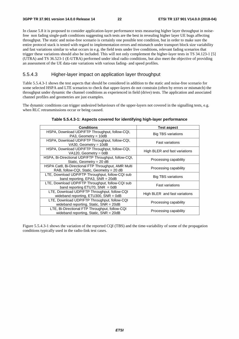
ETSI
ETSI TR 137 901 V14.0.0 (2018-04)223GPP TR 37.901 version 14.0.0 Release 14
In clause 5.8 it is proposed to consider application-layer performance tests measuring higher layer throughput in noise-free non fading single-path conditions suggesting such tests are the best in revealing higher layer UE bugs affecting throughput. The static and noise-free scenario is certainly one possible test condition, but in order to make sure the entire protocol stack is tested with regard to implementation errors and mismatch under transport block size variability and fast variations similar to what occurs in e.g. the field tests under live conditions, relevant fading scenarios that trigger these variations should also be included. This will not only complement the higher-layer tests in TS 34.123-1 [5] (UTRA) and TS 36.523-1 (E-UTRA) performed under ideal radio conditions, but also meet the objective of providing an assessment of the UE data-rate variations with various fading- and speed profiles.
5.5.4.3 Higher-layer impact on application layer throughput
Table 5.5.4.3-1 shows the test aspects that should be considered in addition to the static and noise-free scenario for some selected HSPA and LTE scenarios to check that upper-layers do not constrain (often by errors or mismatch) the throughput under dynamic the channel conditions as experienced in field (drive) tests. The application and associated channel profiles and geometries are just examples.
The dynamic conditions can trigger undesired behaviours of the upper-layers not covered in the signalling tests, e.g. when RLC retransmissions occur or being caused.
Table 5.5.4.3-1: Aspects covered for identifying high-layer performance
Conditions Test aspect HSPA, Download UDP/FTP Throughput, follow-CQI,
PA3, Geometry = 10dB Big TBS variations
HSPA, Download UDP/FTP Throughput, follow-CQI, VA30, Geometry = 10dB Fast variations
HSPA, Download UDP/FTP Throughput, follow-CQI, VA120, Geometry = 0dB High BLER and fast variations
HSPA, Bi-Directional UDP/FTP Throughput, follow-CQI, Static, Geometry = 20 dB
Processing capability
HSPA Cat8, Bi-Directional FTP Throughput, AMR Multi RAB, follow-CQI, Static, Geometry = 20 dB Processing capability
LTE, Download UDP/FTP Throughput, follow-CQI sub band reporting, EPA3, SNR = 20dB Big TBS variations
LTE, Download UDP/FTP Throughput, follow-CQI sub band reporting ETU70, SNR = 0dB
Fast variations
LTE, Download UDP/FTP Throughput, follow-CQI wideband reporting, ETU300, SNR = 0dB High BLER and fast variations
LTE, Download UDP/FTP Throughput, follow-CQI wideband reporting, Static, SNR = 20dB Processing capability
LTE, Bi-Directional FTP Throughput, follow-CQI wideband reporting, Static, SNR = 20dB Processing capability
Figure 5.5.4.3-1 shows the variation of the reported CQI (TBS) and the time-variability of some of the propagation conditions typically used in the radio-link test cases.
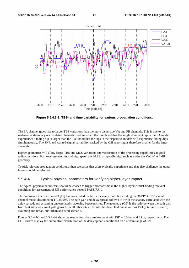
ETSI
ETSI TR 137 901 V14.0.0 (2018-04)233GPP TR 37.901 version 14.0.0 Release 14
Figure 5.5.4.3-1: TBS- and time variability for various propagation conditions.
The PA channel gives rise to larger TBS variations than the more dispersive VA and PB channels. This is due to the wide-sense stationary uncorrelated channels used, in which the likelihood that the single dominant tap in the PA model experiences a fading dip is larger than the likelihood that the taps in the dispersive models will experience fading dips simultaneously. The SNR and wanted-signal variability tracked by the CSI reporting is therefore smaller for the latter channels.
Higher geometries will allow larger TBS and MCS variations and verification of the processing capabilities at good radio conditions. For lower geometries and high speed the BLER is typically high such as under the VA120 at 0 dB geometry.
To pick relevant propagation conditions, then scenarios that users typically experience and that also challenge the upper layers should be selected.
5.5.4.4 Typical physical parameters for verifying higher-layer impact
The typical physical parameters should be chosen to trigger mechanisms in the higher layers whilst finding relevant conditions for assessment of UE performance beyond PASS/FAIL.
The empirical Greenstein model [15] has constituted the basis for many models including the 3GPP/3GPP2 spatial channel model described in TR 25.996. The path gain and delay spread follow [15] with the shadow correlated with the delay spread, and assuming uncorrelated shadowing between sites. The geometry (C/I) is the ratio between the path gain from best site and sum of path gains from all other sites. 100 sites has been laid out at various ISD (inter-site distance) assuming and urban, sub-urban and rural scenario.
Figures 5.5.4.4-1 and 5.5.4.4-2 show the results for urban environment with ISD = 0.5 km and 3 km, respectively. The CDF curves display the cumulative distribution of the delay spread conditioned on a certain range of C/I.
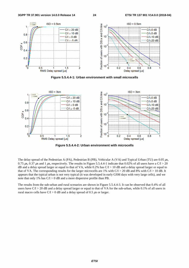
ETSI
ETSI TR 137 901 V14.0.0 (2018-04)243GPP TR 37.901 version 14.0.0 Release 14
Figure 5.5.4.4-1: Urban environment with small microcells
Figure 5.5.4.4-2: Urban environment with microcells
The delay spread of the Pedestrian A (PA), Pedestrian B (PB), Vehicular A (VA) and Typical Urban (TU) are 0.05 μs, 0.75 μs, 0.37 μs and 1 μs, respectively. The results in Figure 5.5.4.4-1 indicate that 0.02% of all users have a C/I > 20 dB and a delay spread larger or equal to that of VA, while 0.2% has C/I > 10 dB and a delay spread larger or equal to that of VA. The corresponding results for the larger microcells are 1% with C/I > 20 dB and 8% with C/I > 10 dB. It appears that the typical urban is not very typical (it was developed in early GSM days with very large cells), and we note that only 1% has C/I > 0 dB and a more dispersive profile than PB.
The results from the sub-urban and rural scenarios are shown in Figure 5.5.4.4-3. It can be observed that 0.4% of all users have C/I > 20 dB and a delay spread larger or equal to that of VA for the sub-urban, while 0.1% of all users in rural macro cells have C/I > 0 dB and a delay spread of 0.5 μs or larger.
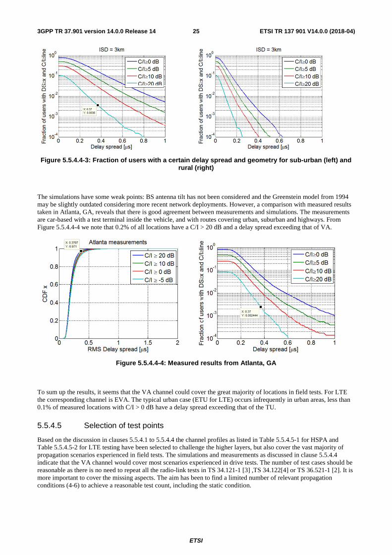
ETSI
ETSI TR 137 901 V14.0.0 (2018-04)253GPP TR 37.901 version 14.0.0 Release 14
Figure 5.5.4.4-3: Fraction of users with a certain delay spread and geometry for sub-urban (left) and rural (right)
The simulations have some weak points: BS antenna tilt has not been considered and the Greenstein model from 1994 may be slightly outdated considering more recent network deployments. However, a comparison with measured results taken in Atlanta, GA, reveals that there is good agreement between measurements and simulations. The measurements are car-based with a test terminal inside the vehicle, and with routes covering urban, suburban and highways. From Figure 5.5.4.4-4 we note that 0.2% of all locations have a C/I > 20 dB and a delay spread exceeding that of VA.
Figure 5.5.4.4-4: Measured results from Atlanta, GA
To sum up the results, it seems that the VA channel could cover the great majority of locations in field tests. For LTE the corresponding channel is EVA. The typical urban case (ETU for LTE) occurs infrequently in urban areas, less than 0.1% of measured locations with C/I > 0 dB have a delay spread exceeding that of the TU.
5.5.4.5 Selection of test points
Based on the discussion in clauses 5.5.4.1 to 5.5.4.4 the channel profiles as listed in Table 5.5.4.5-1 for HSPA and Table 5.5.4.5-2 for LTE testing have been selected to challenge the higher layers, but also cover the vast majority of propagation scenarios experienced in field tests. The simulations and measurements as discussed in clause 5.5.4.4 indicate that the VA channel would cover most scenarios experienced in drive tests. The number of test cases should be reasonable as there is no need to repeat all the radio-link tests in TS 34.121-1 [3] ,TS 34.122[4] or TS 36.521-1 [2]. It is more important to cover the missing aspects. The aim has been to find a limited number of relevant propagation conditions (4-6) to achieve a reasonable test count, including the static condition.
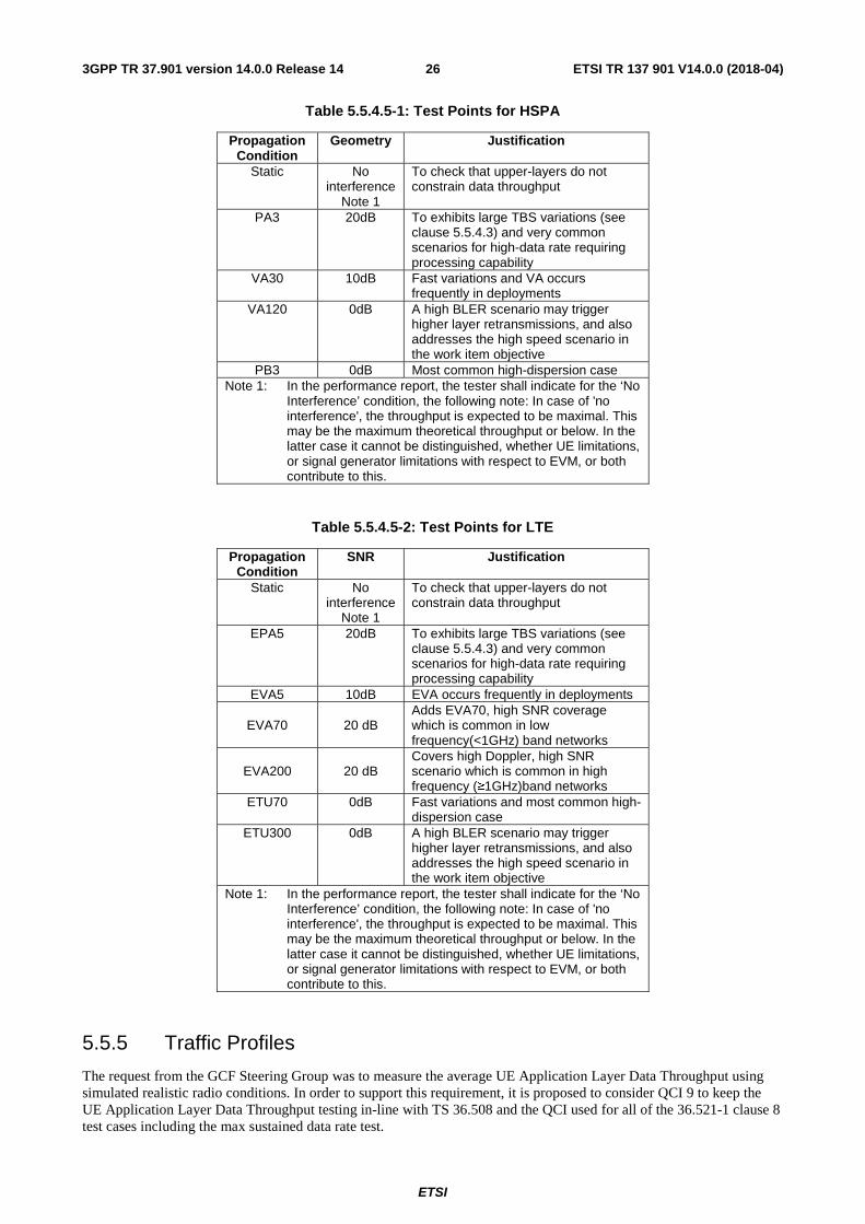
ETSI
ETSI TR 137 901 V14.0.0 (2018-04)263GPP TR 37.901 version 14.0.0 Release 14
Table 5.5.4.5-1: Test Points for HSPA
Propagation Condition
Geometry Justification
Static No interference
Note 1
To check that upper-layers do not constrain data throughput
PA3 20dB To exhibits large TBS variations (see clause 5.5.4.3) and very common scenarios for high-data rate requiring processing capability
VA30 10dB Fast variations and VA occurs frequently in deployments
VA120 0dB A high BLER scenario may trigger higher layer retransmissions, and also addresses the high speed scenario in the work item objective
PB3 0dB Most common high-dispersion case Note 1: In the performance report, the tester shall indicate for the ‘No
Interference’ condition, the following note: In case of 'no interference', the throughput is expected to be maximal. This may be the maximum theoretical throughput or below. In the latter case it cannot be distinguished, whether UE limitations, or signal generator limitations with respect to EVM, or both contribute to this.
Table 5.5.4.5-2: Test Points for LTE
Propagation Condition
SNR Justification
Static No interference
Note 1
To check that upper-layers do not constrain data throughput
EPA5 20dB To exhibits large TBS variations (see clause 5.5.4.3) and very common scenarios for high-data rate requiring processing capability
EVA5 10dB EVA occurs frequently in deployments
EVA70 20 dB Adds EVA70, high SNR coverage which is common in low frequency(<1GHz) band networks
EVA200 20 dB Covers high Doppler, high SNR scenario which is common in high frequency (≥1GHz)band networks
ETU70 0dB Fast variations and most common high-dispersion case
ETU300 0dB A high BLER scenario may trigger higher layer retransmissions, and also addresses the high speed scenario in the work item objective
Note 1: In the performance report, the tester shall indicate for the ‘No Interference’ condition, the following note: In case of 'no interference', the throughput is expected to be maximal. This may be the maximum theoretical throughput or below. In the latter case it cannot be distinguished, whether UE limitations, or signal generator limitations with respect to EVM, or both contribute to this.
5.5.5 Traffic Profiles
The request from the GCF Steering Group was to measure the average UE Application Layer Data Throughput using simulated realistic radio conditions. In order to support this requirement, it is proposed to consider QCI 9 to keep the UE Application Layer Data Throughput testing in-line with TS 36.508 and the QCI used for all of the 36.521-1 clause 8 test cases including the max sustained data rate test.
ETSI
ETSI TR 137 901 V14.0.0 (2018-04)273GPP TR 37.901 version 14.0.0 Release 14
5.6 Data Transfer Scenarios
5.6.1 FTP Transfers
It is proposed to execute the following data transfer scenarios for FTP.
- Downlink Only
- Uplink Only
- Bi-Directional (concurrent and alternating based on test purpose)
5.6.2 UDP Transfers
It is proposed to execute the following data transfer scenarios for UDP.
- Downlink Only
- Uplink Only
- Bi-Directional (concurrent)
5.7 Statistical Analysis
5.7.1 Layer 1 Receiver and Performance Tests
When L1 throughput (payload bits/time) is measured during receiver and performance tests, one has to consider the question: In what range around Tmeasured is the true throughput, Ttrue? The parameters in receiver and performance tests are better known and allow us to answer this question.
In L1 throughput tests, we have a fixed reference channel so the number of payload bits per block is constant. In a fixed reference channel, we know the maximum throughput.
If the throughput limit is defined as 70% of the maximum throughput, a UE near the limit receives 70% correct blocks of constant TBS (returns an ACK) and 30% corrupted or missed blocks (returns NACK or statDTX). If a process works within an incremental redundancy sequence, the samples are not independent. Nevertheless, the error events (corrupted or missed blocks) are mainly independent.
These facts allow one to derive statistics which tells us the variance of the true throughput around the measured one. These statistics are used to determine the minimum number of samples for a given confidence level for the pass/fail decision.
Another aspect that impacts minimum test time is fading. The minimum test time due to fading is long for slow speed propagation profiles and short for high speed ones. The longer minimum test time of the two aspects (statistical or fading) applies.
For UTRAN, each minimum test time is derived from the speed in the profile. The longest time is 164 seconds for the slow speed fading profiles.
For LTE the minimum test time is simulated for each test case, hence we have a large variety of minimum test times.
- Longest: 150 000 minimum number of active samples = 1500 seconds net test time
- Shortest: 1366 minimum number of active samples = 13.66 seconds net test time
Most of the layer 1 receiver and performance tests in UTRAN and LTE are governed by the test time due to fading.
5.7.2 Application Layer Data Throughput
During the application layer data throughput, we can also record ACK, NACK and stat DTX in order to calculate the L1 payload bit throughput, although this is not the main target of the application layer test. We can consider the same
ETSI
ETSI TR 137 901 V14.0.0 (2018-04)283GPP TR 37.901 version 14.0.0 Release 14
question: In what range around Tmeasured is the true throughput, Ttrue? However, the parameters for this measurement are not as controlled for us to answer the same question.
In contrast to fixed reference channel, the TBS variation is intended to be high and/or fast to exercise aspects of the UE that may impact application layer data throughput. This means that we have high variability in the range of payload bits per block. Therefore, the definition of a maximum throughput at the physical layer is not meaningful as the target throughput is not easily defined.
While throughput is composed of one ratio, (correct blocks) / (correct blocks + (corrupted or missed blocks)), the throughput can be achieved by different compositions of correctly received TBS's. Of course, L1 throughput is still of a statistical nature but the characteristic of the statistics are unknown to us. Hence it is not possible for us to derive a variance of true throughput around the measured throughput.
In contrast to layer 1 receiver and performance tests above, the measured throughput is the final result and not the pass/fail decision.
For fixed reference channel testing, the UE is compared against a predefined limit. Therefore, statistics can be derived to determine the minimum number of samples for a given confidence level for the pass/fail decision. In UE application layer throughput testing, it is desirable to compare the throughput against a variable throughput target or a reference UE. The confidence level in this context is more complex than for a predefined pass/fail limit. We are not necessarily able to calculate the confidence level.
The application layer data throughput is impacted by the L1 throughput. The L1 throughput is inaccessible for analytical statistics as shown above. It can also be expected that the application layer SDUs are not independent. Quite to the contrary, they are dependent in an unknown way. Hence the application layer throughput is inaccessible for statistics as well. Nevertheless, the application layer data throughput is of a statistical nature.
5.7.3 Minimum Test Time
Application layer throughput is of a statistical nature but the statistics are unknown to us.
Hence, we are not able to give a variance of the measured throughput around the true throughput which results in the following complementary statements.
- We are not able to give a confidence level of the measurement when given a predefined test time
- We are not able to calculate a minimum test time for a given confidence level.
Therefore, for HSPA, the recommendation for minimum test time is 164 seconds which is derived from lowest speed fading (crossing of 990 wavelengths when travelling with the speed given in the fading profile). This proved its worth during the past and seems meaningful and applicable for the other higher speeds. For static testing, 60 seconds is recommended.
For LTE, the recommended minimum test time for static testing is also set to 60s.
For fading cases, Annex G.3.5 of TS 36.521-1 [2] contains approximately 50 test times for throughput tests with different demodulation scenarios. These scenarios contain the fading profiles that have been proposed in clause 5.5.2 of this document.
The demodulation scenarios are characterised by certain parameters: BW, RB allocation, modulation and coding, antenna configuration. These parameters are similar but not entirely consistent for all of the UE application layer data throughput test conditions. Therefore, it is not possible to select specific test times from Annex G.3.5 of TS 36.521-1 [2] for the purpose of UE application layer data throughput testing. However, when deciding the minimum test times based on the parameters in this document, it is proposed to reuse, as far as possible, the minimum test times from Annex G.3.5 of TS 36.521-1 [2].
5.8 Impact of Modem Performance in Application Layer Throughput
The modem performance has a very big role in application layer data throughput performance when tests are performed in noisy conditions under multipath fading scenarios. The sub-clause 5.8.1 demonstrates how big differences there are in modem performance when measured from many different UEs in commercial conformance test systems. Then sub-
ETSI
ETSI TR 137 901 V14.0.0 (2018-04)293GPP TR 37.901 version 14.0.0 Release 14
clause 5.8.2 discusses about modem performance in application layer throughput tests and gives some easy-to-understand reasons why modem performance also dominates in application layer throughput tests.
5.8.1 Modem Performance in current TS 34.121-1/TS 34.122 Conformance Tests
Section 9 of TS 34.121-1 [3] / TS 34.122 [4] contains a lot of HSDPA throughput test cases for different UE categories and for different UE performance types such as Type 0 (based on basic Rake receiver), Type 1(based on Rx Diversity), Type 2 (Based on Equaliser), Type 3 (based on RxDiv + EQU) and Type 3i (based on Interference aware Type3 receiver). Each of these test cases includes a lot of test points where following parameters are being varied:
- Noise level (Low, Mid and High Geometry)
- Fading Type and UE speed (PA3, PB3, VA30, VA120)
- HSDPA power level (Low or High Power)
- Modulation type (QPSK, 16QAM, 64QAM)
Most of these section 9 test cases have been verified and validated in multiple commercially available conformance test platforms. For UE conformance purposes these validated test cases declare only PASS or FAIL but detailed test reports contain also the measured throughput results of each test points.
While conformance test cases verify that UE fulfils the 3GPP minimum requirements, the detailed test reports can be also used to evaluate how good modem performance UE has by evaluating how big margins each UE has to 3GPP minimum requirements.
As an example, below there are three different figures to evaluate the modem performance in some selected TS 34.121-1 [3] test cases. The results have been collected from official conformance test platform where test equipment is calibrated to fulfil the tight 3GPP accuracy requirements, and testing time also follows 3GPP requirements to give statistically reliable and reproducible test results. The throughput results have been normalised to the best performing UE in each test point to give better understanding about relative UE throughput performance. Note that each of these UEs fulfils the 3GPP minimum requirements but nevertheless the differences in throughput performance among UEs are quite big.
Figure 5.8.1-1 shows HSDPA throughput performance in TC 9.2.1A that is testing UEs supporting 5 HSDPA codes (CAT6). Results have been collected from 11 different UEs from 6 different UE vendors. The 3GPP minimum requirements in this test case are based on Type 0 (Basic RAKE receiver), and thus many UEs fulfil 3GPP requirements with quite a big margins. This figure also shows how different UE vendors have been managed to improve the throughput in their different platform versions. The Figure 5.8.1-1 shows that in most demanding test points some UE can achieve only about 50% of the best UE’s throughput. On the other hand, some of these tests points are so easy that almost every UE has achieved the best possible throughput in given test point conditions.
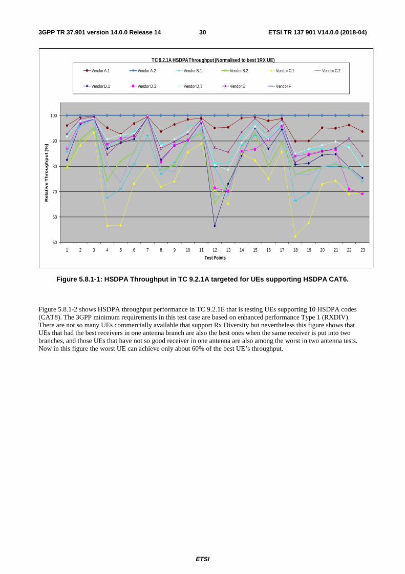
ETSI
ETSI TR 137 901 V14.0.0 (2018-04)303GPP TR 37.901 version 14.0.0 Release 14
Figure 5.8.1-1: HSDPA Throughput in TC 9.2.1A targeted for UEs supporting HSDPA CAT6.
Figure 5.8.1-2 shows HSDPA throughput performance in TC 9.2.1E that is testing UEs supporting 10 HSDPA codes (CAT8). The 3GPP minimum requirements in this test case are based on enhanced performance Type 1 (RXDIV). There are not so many UEs commercially available that support Rx Diversity but nevertheless this figure shows that UEs that had the best receivers in one antenna branch are also the best ones when the same receiver is put into two branches, and those UEs that have not so good receiver in one antenna are also among the worst in two antenna tests. Now in this figure the worst UE can achieve only about 60% of the best UE’s throughput.
50
60
70
80
90
100
1 2 3 4 5 6 7 8 9 10 11 12 13 14 15 16 17 18 19 20 21 22 23
Re
lati
ve
Th
rou
gh
pu
t [%
]
Test Points
TC 9.2.1A HSDPA Throughput (Normalised to best 1RX UE)
Vendor A.1 Vendor A.2 Vendor B.1 Vendor B.2 Vendor C.1 Vendor C.2
Vendor D.1 Vendor D.2 Vendor D.3 Vendor E Vendor F
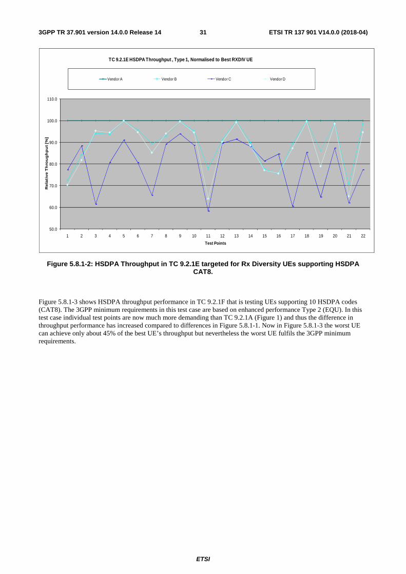
ETSI
ETSI TR 137 901 V14.0.0 (2018-04)313GPP TR 37.901 version 14.0.0 Release 14
Figure 5.8.1-2: HSDPA Throughput in TC 9.2.1E targeted for Rx Diversity UEs supporting HSDPA CAT8.
Figure 5.8.1-3 shows HSDPA throughput performance in TC 9.2.1F that is testing UEs supporting 10 HSDPA codes (CAT8). The 3GPP minimum requirements in this test case are based on enhanced performance Type 2 (EQU). In this test case individual test points are now much more demanding than TC 9.2.1A (Figure 1) and thus the difference in throughput performance has increased compared to differences in Figure 5.8.1-1. Now in Figure 5.8.1-3 the worst UE can achieve only about 45% of the best UE’s throughput but nevertheless the worst UE fulfils the 3GPP minimum requirements.
50.0
60.0
70.0
80.0
90.0
100.0
110.0
1 2 3 4 5 6 7 8 9 10 11 12 13 14 15 16 17 18 19 20 21 22
Re
lati
ve
Th
rou
gh
pu
t [%
]
Test Points
TC 9.2.1E HSDPA Throughput , Type 1, Normalised to Best RXDIV UE
Vendor A Vendor B Vendor C Vendor D
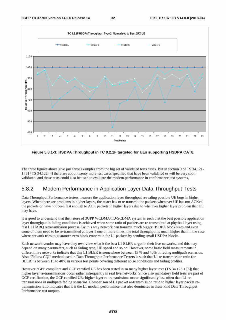
ETSI
ETSI TR 137 901 V14.0.0 (2018-04)323GPP TR 37.901 version 14.0.0 Release 14
Figure 5.8.1-3: HSDPA Throughput in TC 9.2.1F targeted for UEs supporting HSDPA CAT8.
The three figures above give just three examples from the big set of validated tests cases. But in section 9 of TS 34.121-1 [3] / TS 34.122 [4] there are about twenty more test cases specified that have been validated or will be very soon validated and those tests could also be used to evaluate the modem performance in conformance test systems,
5.8.2 Modem Performance in Application Layer Data Throughput Tests
Data Throughput Performance testers measure the application layer throughput revealing possible UE bugs in higher layers. When there are problems in higher layers, the tester has to re-transmit the packets whenever UE has not ACKed the packets or have not been fast enough to ACK packets in higher layers due to whatever higher layer problem that UE may have.
It is good to understand that the nature of 3GPP WCDMA/TD-SCDMA system is such that the best possible application layer throughput in fading conditions is achieved when some ratio of packets are re-transmitted at physical layer using fast L1 HARQ retransmission process. By this way network can transmit much bigger HSDPA block sizes and even some of them need to be re-transmitted at layer 1 one or more times, the total throughput is much higher than in the case where network tries to guarantee zero block error ratio for L1 packets by sending small HSDPA blocks.
Each network vendor may have they own view what it the best L1 BLER target in their live networks, and this may depend on many parameters, such as fading type, UE speed and so on. However, some basic field measurements in different live networks indicate that this L1 BLER is somewhere between 15 % and 40% in fading multipath scenarios. Also “Follow CQI” method used in Data Throughput Performance Testers is such that L1 re-transmission ratio (or BLER) is between 15 to 40% in various test points covering different noise conditions and fading profiles.
However 3GPP compliant and GCF certified UE has been tested in so many higher layer tests (TS 34.123-1 [5]) that higher layer re-transmissions occur rather infrequently in real live networks. Since also mandatory field tests are part of GCF certification, the GCF certified UEs higher layer re-transmissions occur significantly less often than L1 re-transmissions in multipath fading scenarios. Comparison of L1 packet re-transmission ratio to higher layer packet re-transmission ratio indicates that it is the L1 modem performance that also dominates in these kind Data Throughput Performance test outputs.
40.0
50.0
60.0
70.0
80.0
90.0
100.0
110.0
1 2 3 4 5 6 7 8 9 10 11 12 13 14 15 16 17 18 19 20 21 22 23
Re
lati
ve
Th
rou
gh
pu
t [%
]
Test Points
TC 9.2.1F HSDPA Throughput , Type 2, Normalised to Best 1RX UE
Vendor A Vendor B Vendor C Vendor D
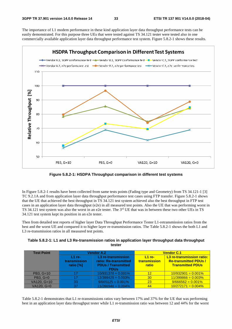
ETSI
ETSI TR 137 901 V14.0.0 (2018-04)333GPP TR 37.901 version 14.0.0 Release 14
The importance of L1 modem performance in these kind application layer data throughput performance tests can be easily demonstrated. For this purpose three UEs that were tested against TS 34.121 tester were tested also in one commercially available application layer data throughput performance test system. Figure 5.8.2-1 shows these results.
Figure 5.8.2-1: HSDPA Throughput comparison in different test systems
In Figure 5.8.2-1 results have been collected from same tests points (Fading type and Geometry) from TS 34.121-1 [3] TC 9.2.1A and from application layer data throughput performance test cases using FTP transfer. Figure 5.8.2-1 shows that the UE that achieved the best throughput in TS 34.121 test system achieved also the best throughput in FTP test cases in an application layer data throughput (e2e) in all measured test points. Also the UE that was performing worst in TS 34.121 test system was also the worst in an e2e tester. The 3rd UE that was in between these two other UEs in TS 34.121 test system kept its position in an e2e tester.
Then from detailed test reports of higher layer Data Throughput Performance Tester L1-retransmission ratios from the best and the worst UE and compared it to higher layer re-transmission ratios. The Table 5.8.2-1 shows the both L1 and L3 re-transmission ratios in all measured test points.
Table 5.8.2-1: L1 and L3 Re-transmission ratios in application layer throughput data throughput tester
Test Point Vendor A.2 Vendor C.1 L1 re-
transmission ratio [%]
L3 re-transmission ratio: Re-transmitted PDUs / Transmitted
PDUs
L1 re-transmission
ratio
L3 re-transmission ratio: Re-transmitted PDUs /
Transmitted PDUs
PB3, G=10 17 10/931378 = 0.001% 12 10/932901 = 0.001% PB3, G=0 17 12/399429 = 0.003% 30 11/399866 = 0.003%
VA120, G=10 33 9/665125 = 0.001% 23 9/666562 = 0.001% VA120, G=0 37 11/266946 = 0.004% 44 10/272171 = 0.004%
Table 5.8.2-1 demonstrates that L1 re-transmissions ratios vary between 17% and 37% for the UE that was performing best in an application layer data throughput tester while L1 re-transmission ratio was between 12 and 44% for the worst
50
60
70
80
90
100
110
PB3, G=10 PB3, G=0 VA120, G=10 VA120, G=0
Re
lati
ve
Th
rou
gh
pu
t [%
]
HSDPA Throughput Comparison in Different Test Systems
Vendor A.2, 3GPP conformance test Vendor B.2, 3GPP Conformance test Vendor C.1, 3GPP conformance test
Vendor A.2, e2e performance test Vendor B.2, e2e performance test Vendor C.1, e2e performance test
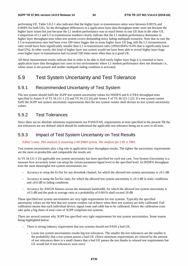
ETSI
ETSI TR 137 901 V14.0.0 (2018-04)343GPP TR 37.901 version 14.0.0 Release 14
performing UE. Table 5.8.2-1 also indicates that the higher layer re-transmission ratios were between 0.001% and 0.004% for both UEs. So the throughput differences in a application layer data throughput tester were not because the higher layer issues but just because the L1 modem performance was so much better in one UE than in the other UE. Comparison of L1 and L3 re-transmission numbers clearly indicate that the L1 modem performance dominates in higher layer throughput tests when test system covers demanding noisy fading multipath scenarios. Note that in case the L3 re-transmission ratio had been even 100 times bigger due to some higher layer UE bug, still the L3 retransmission ratio would have been significantly smaller than L1 re-transmission ratio (100x0.004%=0.4% that is significantly lower than12%). In other words, this kind of higher layer test system would not have been able to reveal higher layer bugs even higher layer re-transmission had occurred 100 times more often than in a good UE.
All these measurement results indicate that in order to be able to find easily higher layer bugs it is essential to have application layer data throughput test cases in test environments where L1 modem performance does not dominate i.e., where noise is not present and neither multipath fading condition is activated.
5.9 Test System Uncertainty and Test Tolerance
5.9.1 Recommended Uncertainty of Test System
The test system should fulfil the 3GPP test system uncertainty values for HSDPA and E-UTRA throughput tests specified in Annex F of TS 34.121-1 [3] and TS 34.122 [4] and Annex F of TS 36.521-1 [2]. If a test system cannot fulfil the 3GPP test system uncertainty requirements then the test system vendor shall declare its test system uncertainty values.
5.9.2 Test Tolerances
Since there are no absolute minimum requirements nor PASS/FAIL requirements in tests specified in the present TR the test tolerances are not defined which should be understood the applicable test tolerance being set to zero in all tests.
5.9.3 Impact of Test System Uncertainty on Test Results
Editor’s note: This analysis is assuming a WCDMA system. The analysis for LTE is TBD.
Test system uncertainties play a big role in application layer throughput results. The tighter the uncertainty requirements are the more re-producible and comparable the results are.
In TS 34.121-1 [3] applicable test system uncertainty has been specified for each test case. Test System Uncertainty is a measure how accurately tester can setup the certain parameter/signal level to the specified level. In HSDPA throughput tests the most meaningful test system uncertainties are:
- Accuracy to setup the Ec/Ior for any downlink channel, for which the allowed test system uncertainty is ±0.1 dB
- Accuracy to setup the Îor/Ioc ratio, for which the allowed test system uncertainty is ±0.3 dB in static conditions and ±0.6 dB in fading conditions
- Accuracy for AWGN flatness across the minimum bandwidth, for which the allowed test system uncertainty is ±0.5 dB and the peak to average ratio at a probability of 0.001% shall exceed 10 dB
These specified test system uncertainties are very tight requirements for test systems. Typically the specified uncertainty values are the best that test system vendors can achieve when their test systems are fully calibrated. Full calibration means that each individual device, signal route and cable has to be calibrated. Hence the calibration costs take quite a big share of total costs of 3GPP compliant test systems.
There are several reasons why 3GPP has specified very tight requirements for test system uncertainties. Some reason being highlighted below:
- There is strong industry requirement that test systems should not PASS a bad UE.
- Loose test system uncertainties results big test tolerances. The smaller the test tolerances are the smaller is the probability that a test system passes a bad UE. (Since minimum requirements are relaxed by the amount of test tolerances there is a small chance that a bad UE passes the test thanks to relaxed test requirements but UE would fail if test tolerances were zero)
ETSI
ETSI TR 137 901 V14.0.0 (2018-04)353GPP TR 37.901 version 14.0.0 Release 14
- The tests should be as reproducible as possible
- Without accurate test system calibration the test result may change from day to day / from frequency to frequency
- The test results should be as comparable as possible from device to device and from test system vendor to test system vendor
- All test systems should give a same PASS/FAIL verdict for one UE, and also each test system should give roughly the same actual test results (e.g., for HSDPA throughput).
The impact of test system uncertainties on HSDPA throughput in different scenarios are demonstrated in Figures 5.9.3-1 and 5.9.3-2 that show the HSDPA throughput in different fading scenarios as a function of Îor/Ioc (=G) value. The nominal G value is 0 dB in Figure 5.9.3-1 and 10 dB in Figure 5.9.3-2.
Figure 5.9.3-1: Impact of G on HSDPA throughput in fading scenarios when G is low
Figure 5.9.3-1 shows that absolute throughput can vary more than 100 kbps even when test system uncertainties for G fulfil the 3GPP requirements given. When uncertainties of G are looser than 3GPP requirements then absolute throughput values differ more than 300 kbps.
Figure 5.9.3-2 shows the same phenomena when test system uncertainties are applied to area when G is high. But now when absolute throughput values are higher due to less noise in scenario (G is high) the absolute throughput values differ even more than 1 Mbps when test system uncertainty for G is ±1.5 dB.
300.0
400.0
500.0
600.0
700.0
800.0
900.0
1000.0
-2 -1.5 -1 -0.5 0 0.5 1 1.5 2
Tput
G
Impact of G on HSDPA throughput
STATIC
PB3
PA3
VA120
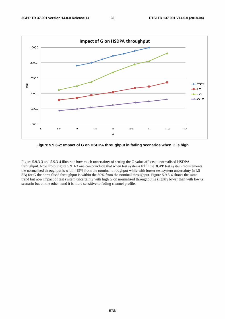
ETSI
ETSI TR 137 901 V14.0.0 (2018-04)363GPP TR 37.901 version 14.0.0 Release 14
Figure 5.9.3-2: Impact of G on HSDPA throughput in fading scenarios when G is high
Figure 5.9.3-3 and 5.9.3-4 illustrate how much uncertainty of setting the G value affects to normalised HSDPA throughput. Now from Figure 5.9.3-3 one can conclude that when test systems fulfil the 3GPP test system requirements the normalised throughput is within 15% from the nominal throughput while with looser test system uncertainty (±1.5 dB) for G the normalised throughput is within the 30% from the nominal throughput. Figure 5.9.3-4 shows the same trend but now impact of test system uncertainty with high G on normalised throughput is slightly lower than with low G scenario but on the other hand it is more sensitive to fading channel profile.
1000.0
1500.0
2000.0
2500.0
3000.0
3500.0
8 8.5 9 9.5 10 10.5 11 11.5 12
Tput
G
Impact of G on HSDPA throughput
STATIC
PB3
PA3
VA120
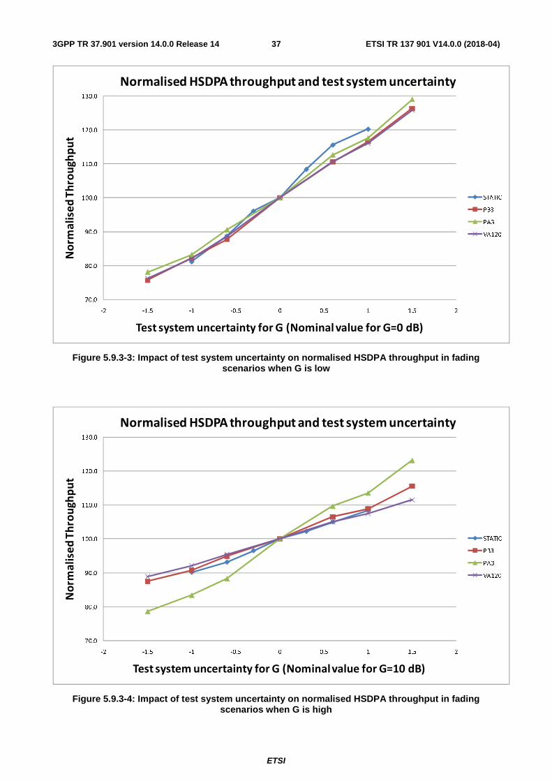
ETSI
ETSI TR 137 901 V14.0.0 (2018-04)373GPP TR 37.901 version 14.0.0 Release 14
Figure 5.9.3-3: Impact of test system uncertainty on normalised HSDPA throughput in fading scenarios when G is low
Figure 5.9.3-4: Impact of test system uncertainty on normalised HSDPA throughput in fading scenarios when G is high
70.0
80.0
90.0
100.0
110.0
120.0
130.0
-2 -1.5 -1 -0.5 0 0.5 1 1.5 2
No
rma
lise
d T
hro
ug
hp
ut
Test system uncertainty for G (Nominal value for G=0 dB)
Normalised HSDPA throughput and test system uncertainty
STATIC
PB3
PA3
VA120
70.0
80.0
90.0
100.0
110.0
120.0
130.0
-2 -1.5 -1 -0.5 0 0.5 1 1.5 2
No
rma
lise
d T
hro
ug
hp
ut
Test system uncertainty for G (Nominal value for G=10 dB)
Normalised HSDPA throughput and test system uncertainty
STATIC
PB3
PA3
VA120
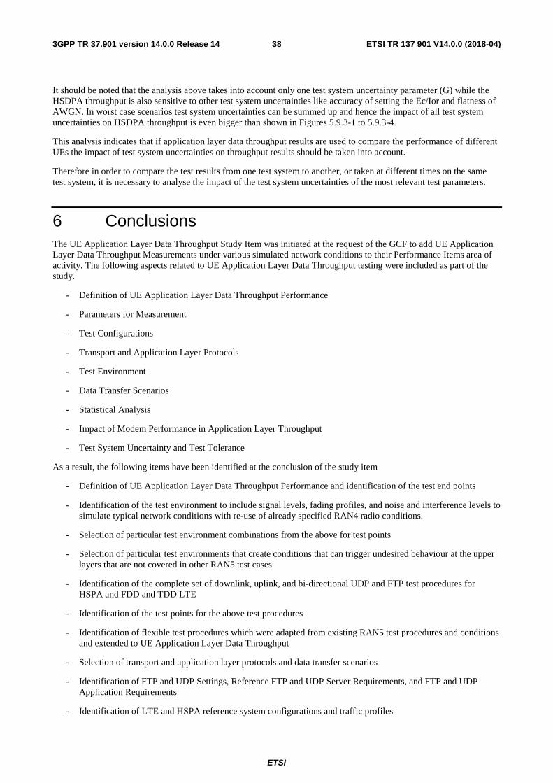
ETSI
ETSI TR 137 901 V14.0.0 (2018-04)383GPP TR 37.901 version 14.0.0 Release 14
It should be noted that the analysis above takes into account only one test system uncertainty parameter (G) while the HSDPA throughput is also sensitive to other test system uncertainties like accuracy of setting the Ec/Ior and flatness of AWGN. In worst case scenarios test system uncertainties can be summed up and hence the impact of all test system uncertainties on HSDPA throughput is even bigger than shown in Figures 5.9.3-1 to 5.9.3-4.
This analysis indicates that if application layer data throughput results are used to compare the performance of different UEs the impact of test system uncertainties on throughput results should be taken into account.
Therefore in order to compare the test results from one test system to another, or taken at different times on the same test system, it is necessary to analyse the impact of the test system uncertainties of the most relevant test parameters.
6 Conclusions The UE Application Layer Data Throughput Study Item was initiated at the request of the GCF to add UE Application Layer Data Throughput Measurements under various simulated network conditions to their Performance Items area of activity. The following aspects related to UE Application Layer Data Throughput testing were included as part of the study.
- Definition of UE Application Layer Data Throughput Performance
- Parameters for Measurement
- Test Configurations
- Transport and Application Layer Protocols
- Test Environment
- Data Transfer Scenarios
- Statistical Analysis
- Impact of Modem Performance in Application Layer Throughput
- Test System Uncertainty and Test Tolerance
As a result, the following items have been identified at the conclusion of the study item
- Definition of UE Application Layer Data Throughput Performance and identification of the test end points
- Identification of the test environment to include signal levels, fading profiles, and noise and interference levels to simulate typical network conditions with re-use of already specified RAN4 radio conditions.
- Selection of particular test environment combinations from the above for test points
- Selection of particular test environments that create conditions that can trigger undesired behaviour at the upper layers that are not covered in other RAN5 test cases
- Identification of the complete set of downlink, uplink, and bi-directional UDP and FTP test procedures for HSPA and FDD and TDD LTE
- Identification of the test points for the above test procedures
- Identification of flexible test procedures which were adapted from existing RAN5 test procedures and conditions and extended to UE Application Layer Data Throughput
- Selection of transport and application layer protocols and data transfer scenarios
- Identification of FTP and UDP Settings, Reference FTP and UDP Server Requirements, and FTP and UDP Application Requirements
- Identification of LTE and HSPA reference system configurations and traffic profiles

ETSI
ETSI TR 137 901 V14.0.0 (2018-04)393GPP TR 37.901 version 14.0.0 Release 14
- Completion of Embedded and Tethered Testing Considerations
- Consideration about the impact of test system uncertainty on test results and confirmation of the Test System Uncertainty Recommendations
- Definition of a reliable and repeatable test environment to ensure the best possible repeatability of the results
- Impact from the lower layers data throughput on the application-layer data throughput
- Identification of the test applicability based on UE capabilities
This technical report includes a set of recommended test procedures for UE Application Layer Data Throughput that is in-line with the study item objectives identified in clause 4.1.
The test procedures are contained in Annex A with the specific test conditions and environments covered in Annex B. The test procedures herein provide a measure of UE data performance at the application layer with no qualification of results (i.e. no verdicts such as "pass/fail", "good", "medium", "bad" will be supplied).
ETSI
ETSI TR 137 901 V14.0.0 (2018-04)403GPP TR 37.901 version 14.0.0 Release 14
Annex A: Test Procedures
A.1 Purpose of annex This annex specifies the test procedures for UE Application Layer Data Throughput Performance. The test procedures are the result of the study item and are the recommended test procedures to be used when evaluating UE Application Layer Data Throughput Performance. The use of "shall" or "must" in the test procedures listed herein is only used to indicate that the test purpose, procedure, and/or result may not be as expected if the specified "shall" or "must" item is not used or followed. As the Technical Report is informative in nature, the use of "shall" or "must" in the test procedures is not meant to imply a specific requirement. Their use is meant to indicate instances where the test objectives of the recommended test procedures may not be achieved.
A.2 UE Application Layer Data Throughput Performance Test Procedures for HSPA
Editor’s Note: The following aspects are either missing or not yet determined:
- MIMO aspects are missing.
A.2.1 General The following test procedures will evaluate the UE Application Layer Data Throughput Performance for HSPA.
For a tethered data configuration, the UE will be tethered to a laptop using the appropriate UE to PC interface Modem or Network Interface Connection (NIC) drivers as recommended by the UE manufacturer for the intended use by the customer/user. In most cases, a laptop with an embedded modem is considered to be a tethered data configuration as opposed to an embedded data configuration due to the UE to PC interface. Refer to the Tethered Data connection diagram in figure C.2.1-1.
For an embedded data configuration, the UE will be the endpoint of the measurement and will have the appropriate data client test applications called out in the test procedures. Refer to the Embedded Data connection diagram in figure C.2.2-1.
The UE should be tested in any data configuration that it supports (tethered and/or embedded).
The performance characteristics for a particular UE will be determined by both the UEs HS-DSCH category and receiver design albeit type 1, 2 or 3. Results shall be recorded for the following clauses which characterize the UE performance across a variety of application layer scenarios utilizing both FTP and UDP protocols.
- FTP Downlink Performance
- UDP Downlink Performance
- FTP Uplink Performance
- UDP Uplink Performance
- Stress Test Performance
- UDP Power Sweep Performance
- UDP Downlink vs. Geometry Factor Performance
All tests shall be performed with a variable reference channel using real-time CQI scheduling with next available TTI corresponding to the UE Category as defined in clause 6A.2.3 CQI Tables of TS 25.214 [6].
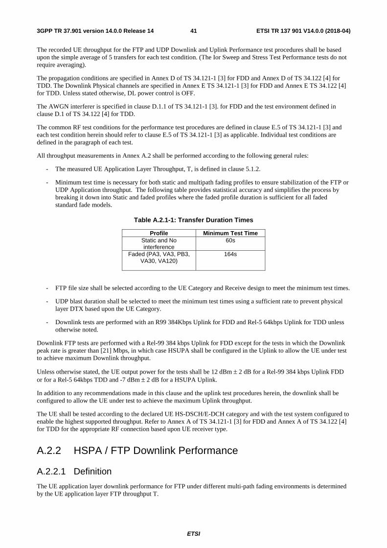
ETSI
ETSI TR 137 901 V14.0.0 (2018-04)413GPP TR 37.901 version 14.0.0 Release 14
The recorded UE throughput for the FTP and UDP Downlink and Uplink Performance test procedures shall be based upon the simple average of 5 transfers for each test condition. (The Ior Sweep and Stress Test Performance tests do not require averaging).
The propagation conditions are specified in Annex D of TS 34.121-1 [3] for FDD and Annex D of TS 34.122 [4] for TDD. The Downlink Physical channels are specified in Annex E TS 34.121-1 [3] for FDD and Annex E TS 34.122 [4] for TDD. Unless stated otherwise, DL power control is OFF.
The AWGN interferer is specified in clause D.1.1 of TS 34.121-1 [3]. for FDD and the test environment defined in clause D.1 of TS 34.122 [4] for TDD.
The common RF test conditions for the performance test procedures are defined in clause E.5 of TS 34.121-1 [3] and each test condition herein should refer to clause E.5 of TS 34.121-1 [3] as applicable. Individual test conditions are defined in the paragraph of each test.
All throughput measurements in Annex A.2 shall be performed according to the following general rules:
- The measured UE Application Layer Throughput, T, is defined in clause 5.1.2.
- Minimum test time is necessary for both static and multipath fading profiles to ensure stabilization of the FTP or UDP Application throughput. The following table provides statistical accuracy and simplifies the process by breaking it down into Static and faded profiles where the faded profile duration is sufficient for all faded standard fade models.
Table A.2.1-1: Transfer Duration Times
Profile Minimum Test Time Static and No interference
60s
Faded (PA3, VA3, PB3, VA30, VA120)
164s
- FTP file size shall be selected according to the UE Category and Receive design to meet the minimum test times.
- UDP blast duration shall be selected to meet the minimum test times using a sufficient rate to prevent physical layer DTX based upon the UE Category.
- Downlink tests are performed with an R99 384Kbps Uplink for FDD and Rel-5 64kbps Uplink for TDD unless otherwise noted.
Downlink FTP tests are performed with a Rel-99 384 kbps Uplink for FDD except for the tests in which the Downlink peak rate is greater than [21] Mbps, in which case HSUPA shall be configured in the Uplink to allow the UE under test to achieve maximum Downlink throughput.
Unless otherwise stated, the UE output power for the tests shall be 12 dBm ± 2 dB for a Rel-99 384 kbps Uplink FDD or for a Rel-5 64kbps TDD and -7 dBm ± 2 dB for a HSUPA Uplink.
In addition to any recommendations made in this clause and the uplink test procedures herein, the downlink shall be configured to allow the UE under test to achieve the maximum Uplink throughput.
The UE shall be tested according to the declared UE HS-DSCH/E-DCH category and with the test system configured to enable the highest supported throughput. Refer to Annex A of TS 34.121-1 [3] for FDD and Annex A of TS 34.122 [4] for TDD for the appropriate RF connection based upon UE receiver type.
A.2.2 HSPA / FTP Downlink Performance
A.2.2.1 Definition
The UE application layer downlink performance for FTP under different multi-path fading environments is determined by the UE application layer FTP throughput T.
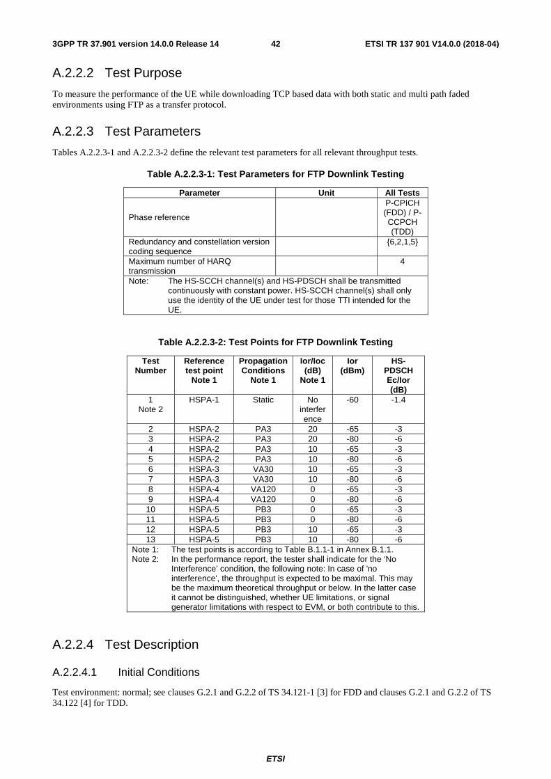
ETSI
ETSI TR 137 901 V14.0.0 (2018-04)423GPP TR 37.901 version 14.0.0 Release 14
A.2.2.2 Test Purpose
To measure the performance of the UE while downloading TCP based data with both static and multi path faded environments using FTP as a transfer protocol.
A.2.2.3 Test Parameters
Tables A.2.2.3-1 and A.2.2.3-2 define the relevant test parameters for all relevant throughput tests.
Table A.2.2.3-1: Test Parameters for FTP Downlink Testing
Parameter Unit All Tests
Phase reference
P-CPICH (FDD) / P-CCPCH (TDD)
Redundancy and constellation version coding sequence {6,2,1,5}
Maximum number of HARQ transmission
4
Note: The HS-SCCH channel(s) and HS-PDSCH shall be transmitted continuously with constant power. HS-SCCH channel(s) shall only use the identity of the UE under test for those TTI intended for the UE.
Table A.2.2.3-2: Test Points for FTP Downlink Testing
Test Number
Reference test point
Note 1
Propagation Conditions
Note 1
Ior/Ioc (dB)
Note 1
Ior (dBm)
HS-PDSCH Ec/Ior (dB)
1 Note 2
HSPA-1 Static No interference
-60 -1.4
2 HSPA-2 PA3 20 -65 -3 3 HSPA-2 PA3 20 -80 -6 4 HSPA-2 PA3 10 -65 -3 5 HSPA-2 PA3 10 -80 -6 6 HSPA-3 VA30 10 -65 -3 7 HSPA-3 VA30 10 -80 -6 8 HSPA-4 VA120 0 -65 -3 9 HSPA-4 VA120 0 -80 -6
10 HSPA-5 PB3 0 -65 -3 11 HSPA-5 PB3 0 -80 -6 12 HSPA-5 PB3 10 -65 -3 13 HSPA-5 PB3 10 -80 -6
Note 1: The test points is according to Table B.1.1-1 in Annex B.1.1. Note 2: In the performance report, the tester shall indicate for the ‘No
Interference’ condition, the following note: In case of 'no interference', the throughput is expected to be maximal. This may be the maximum theoretical throughput or below. In the latter case it cannot be distinguished, whether UE limitations, or signal generator limitations with respect to EVM, or both contribute to this.
A.2.2.4 Test Description
A.2.2.4.1 Initial Conditions
Test environment: normal; see clauses G.2.1 and G.2.2 of TS 34.121-1 [3] for FDD and clauses G.2.1 and G.2.2 of TS 34.122 [4] for TDD.
ETSI
ETSI TR 137 901 V14.0.0 (2018-04)433GPP TR 37.901 version 14.0.0 Release 14
Frequencies to be tested: mid range; see clause G.2.4 of TS 34.121-1 [3] for FDD and clause G.2.4 of TS 34.122 [4] for TDD.
1) Connect the SS (node B emulator) and fader and AWGN noise source to the UE antenna connector based upon UE receiver type as referenced in Annex A of TS 34.121-1 [3] for FDD and Annex A of TS 34.122 [4] for TDD. The downlink connection between the System Simulator and the UE shall be without Additive White Gaussian Noise and have no fading or multipath effects.
2) Connect an application server to the IP output of the SS configured with a FTP server.
3) For a tethered configuration, tether the UE to a laptop configured with FTP client software using the appropriate UE to PC interface Modem or Network Interface Connection (NIC) drivers. For an embedded configuration, ensure that the UE has an FTP client test application available.
4) Set up an HSDPA call using Modem or NIC interface with levels according to table E.5.0 of TS 34.121-1 [3].
5) The test parameters shall be set according to Table A.2.2.3-1 and the configuration of the downlink channels shall be set as defined in clause E.5 of TS 34.121-1 [3] according to UE capability.
A.2.2.4.2 Procedure
1) Once the HSDPA connection is setup, set the parameters for propagation conditions, Ior levels, Ec/Ior, and Îor/Ioc according to Table A.2.2.3-2, as appropriate. The fading simulator shall be configured for static conditions as described in clause D.2.1 of TS 34.121-1 [3] for FDD and clause D.2.1 of TS 34.122 [4] for TDD or for fading conditions as described in table D.2.2.1.A of TS 34.121-1[3] for FDD and clause G.2.4 of TS 34.122 [4] for TDD, as appropriate.
2) Using the FTP client, begin FTP download from the application server of a file sufficient in size for the test duration outlined in Table A.2.1-1 and record Throughput T result. The transport block size used by the SS shall be determined based on UE reported CQI as described in subclause B.2.1.1 (This is iteration 1)
3) Count the number of NACK, ACK and statDTX on the UL HS-DPCCH during the test iteration interval.
4) Repeat steps 2 and 3 for iterations 2 through 5 within the same call as the first iteration.
5) Calculate and record the average throughput of the five iterations.
6) Record the overall number of NACK, ACK and statDTX on the UL HS-DPCCH during the entire test for information.
7) If the HSDPA connection setup needs to be re-established after the subtest, perform the initial HSDPA call setup in accordance with the initial conditions in clause A.2.2.4.1.
8) Repeat steps 1 to 7 for each subtest in Table A.2.2.3-2, as appropriate.
9) Record the IP address type (IPv4 or IPv6) used during the file transfers.
A.2.3 HSPA / UDP Downlink Performance
A.2.3.1 Definition
The UE application layer downlink performance for UDP under different multi-path fading environments is determined by the UE application layer UDP throughput T.
A.2.3.2 Test Purpose
To measure the performance of the UE while downloading UDP based data with both static and multi path faded environments.
A.2.3.3 Test Parameters
Tables A.2.3.3-1 and A.2.3.3-2 define the relevant test parameters for all relevant throughput tests.
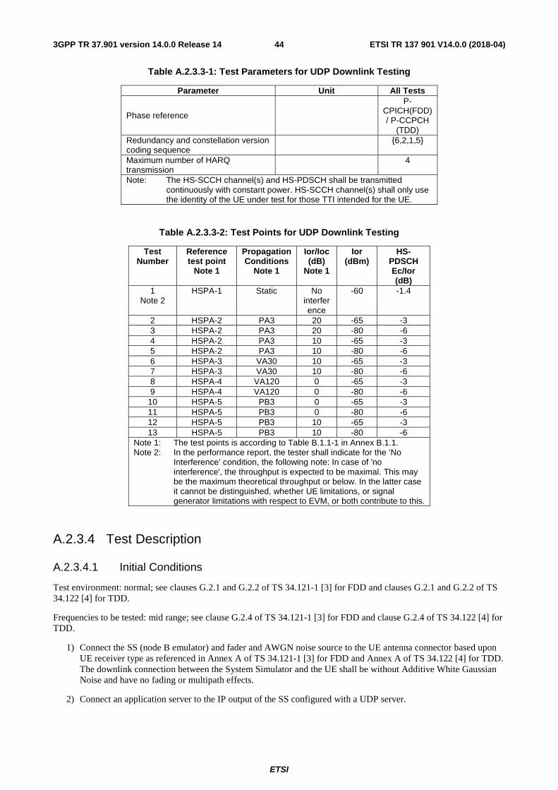
ETSI
ETSI TR 137 901 V14.0.0 (2018-04)443GPP TR 37.901 version 14.0.0 Release 14
Table A.2.3.3-1: Test Parameters for UDP Downlink Testing
Parameter Unit All Tests
Phase reference
P-CPICH(FDD) / P-CCPCH
(TDD) Redundancy and constellation version coding sequence {6,2,1,5}
Maximum number of HARQ transmission 4
Note: The HS-SCCH channel(s) and HS-PDSCH shall be transmitted continuously with constant power. HS-SCCH channel(s) shall only use the identity of the UE under test for those TTI intended for the UE.
Table A.2.3.3-2: Test Points for UDP Downlink Testing
Test Number
Reference test point
Note 1
Propagation Conditions
Note 1
Ior/Ioc (dB)
Note 1
Ior (dBm)
HS-PDSCH Ec/Ior (dB)
1 Note 2
HSPA-1 Static No interference
-60 -1.4
2 HSPA-2 PA3 20 -65 -3 3 HSPA-2 PA3 20 -80 -6 4 HSPA-2 PA3 10 -65 -3 5 HSPA-2 PA3 10 -80 -6 6 HSPA-3 VA30 10 -65 -3 7 HSPA-3 VA30 10 -80 -6 8 HSPA-4 VA120 0 -65 -3 9 HSPA-4 VA120 0 -80 -6
10 HSPA-5 PB3 0 -65 -3 11 HSPA-5 PB3 0 -80 -6 12 HSPA-5 PB3 10 -65 -3 13 HSPA-5 PB3 10 -80 -6
Note 1: The test points is according to Table B.1.1-1 in Annex B.1.1. Note 2: In the performance report, the tester shall indicate for the ‘No
Interference’ condition, the following note: In case of 'no interference', the throughput is expected to be maximal. This may be the maximum theoretical throughput or below. In the latter case it cannot be distinguished, whether UE limitations, or signal generator limitations with respect to EVM, or both contribute to this.
A.2.3.4 Test Description
A.2.3.4.1 Initial Conditions
Test environment: normal; see clauses G.2.1 and G.2.2 of TS 34.121-1 [3] for FDD and clauses G.2.1 and G.2.2 of TS 34.122 [4] for TDD.
Frequencies to be tested: mid range; see clause G.2.4 of TS 34.121-1 [3] for FDD and clause G.2.4 of TS 34.122 [4] for TDD.
1) Connect the SS (node B emulator) and fader and AWGN noise source to the UE antenna connector based upon UE receiver type as referenced in Annex A of TS 34.121-1 [3] for FDD and Annex A of TS 34.122 [4] for TDD. The downlink connection between the System Simulator and the UE shall be without Additive White Gaussian Noise and have no fading or multipath effects.
2) Connect an application server to the IP output of the SS configured with a UDP server.
ETSI
ETSI TR 137 901 V14.0.0 (2018-04)453GPP TR 37.901 version 14.0.0 Release 14
3) For a tethered configuration, tether the UE to a laptop configured with UDP client software using the appropriate UE to PC interface Modem or Network Interface Connection (NIC) drivers. For an embedded configuration, ensure that the UE has an UDP client test application available.
4) Set up an HSDPA call using Modem or NIC interface with levels according to table E.5.0 of TS 34.121-1 [3].
5) The test parameters shall be set according to Table A.2.3.3-1 and the configuration of the downlink channels shall be set as defined in clause E.5 of TS 34.121-1 [3] according to UE capability.
A.2.3.4.2 Procedure
1) Once the HSDPA connection is setup, set the parameters for propagation conditions, Ior levels, Ec/Ior, and Îor/Ioc according to Table A.2.3.3-2, as appropriate. The fading simulator shall be configured for static conditions as described in clause D.2.1 of TS 34.121-1 [3] for FDD and clause D.2.1 of TS 34.122 [4] for TDD or for fading conditions as described in table D.2.2.1.A of TS 34.121-1[3] for FDD and table D.2.2.2.2 of TS 34.122 [4] for TDD, as appropriate.
2) Using the UDP client, begin UDP download from the application server of a file sufficient in size for the test duration outlined in Table A.2.1-1 and record Throughput T result. The transport block size used by the SS shall be determined based on UE reported CQI as described in subclause B.2.1.1 (This is iteration 1)
3) Count the number of NACK, ACK and statDTX on the UL HS-DPCCH during the test iteration interval.
4) Repeat steps 2 and 3 for iterations 2 through 5 within the same call as the first iteration.
5) Calculate and record the average throughput of the five iterations.
6) Record the overall number of NACK, ACK and statDTX on the UL HS-DPCCH during the entire test for information.
7) If the HSDPA connection setup needs to be re-established after the subtest, perform the initial HSDPA call setup in accordance with the initial conditions in clause A.2.3.4.1.
8) Repeat steps 1 to 7 for each subtest in Table A.2.3.3-2, as appropriate.
9) Record the IP address type (IPv4 or IPv6) used during the file transfers.
A.2.4 HSPA / FTP Uplink Performance
A.2.4.1 Definition
The UE application layer uplink performance for FTP under static conditions is determined by the UE application layer FTP throughput T.
A.2.4.2 Test Purpose
To measure the performance of the UE while uploading TCP based data using FTP as a transfer protocol.
A.2.4.3 Test Parameters
Tables A.2.4.3-1 and A.2.4.3-2 define the relevant test parameters and test points for all relevant throughput tests.
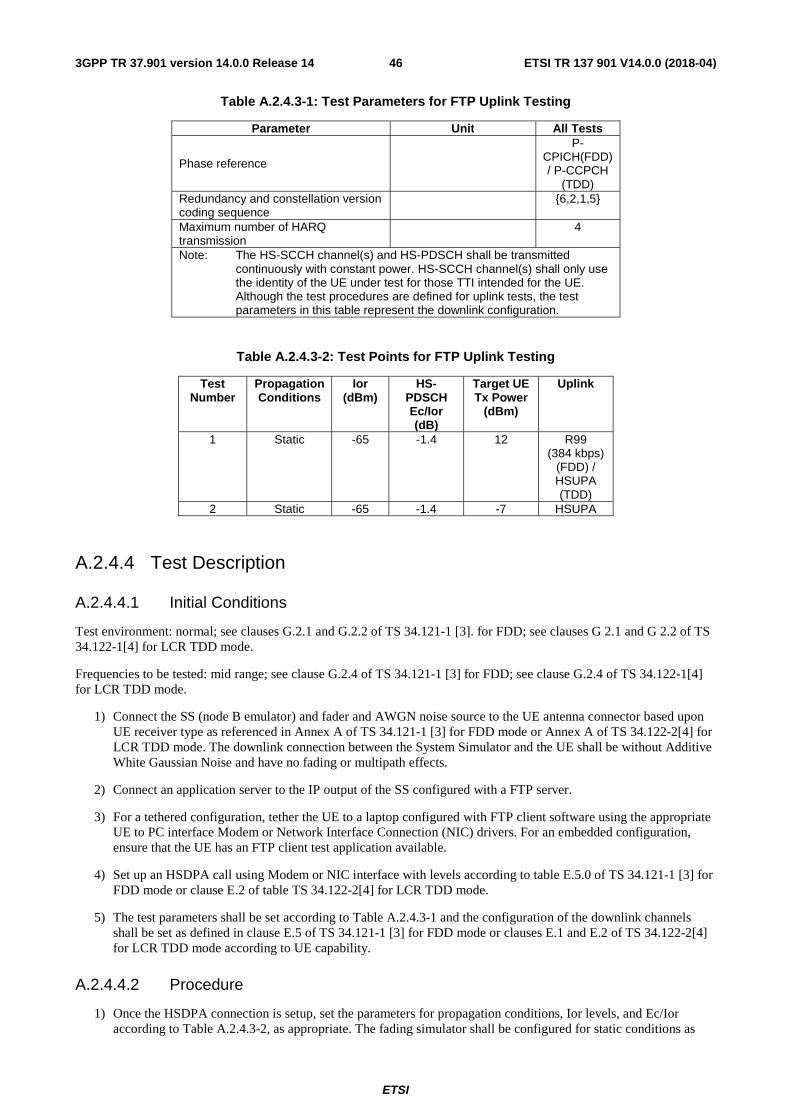
ETSI
ETSI TR 137 901 V14.0.0 (2018-04)463GPP TR 37.901 version 14.0.0 Release 14
Table A.2.4.3-1: Test Parameters for FTP Uplink Testing
Parameter Unit All Tests
Phase reference
P-CPICH(FDD) / P-CCPCH
(TDD) Redundancy and constellation version coding sequence {6,2,1,5}
Maximum number of HARQ transmission 4
Note: The HS-SCCH channel(s) and HS-PDSCH shall be transmitted continuously with constant power. HS-SCCH channel(s) shall only use the identity of the UE under test for those TTI intended for the UE. Although the test procedures are defined for uplink tests, the test parameters in this table represent the downlink configuration.
Table A.2.4.3-2: Test Points for FTP Uplink Testing
Test Number
Propagation Conditions
Ior (dBm)
HS-PDSCH Ec/Ior (dB)
Target UE Tx Power
(dBm)
Uplink
1 Static -65 -1.4 12 R99 (384 kbps)
(FDD) / HSUPA (TDD)
2 Static -65 -1.4 -7 HSUPA
A.2.4.4 Test Description
A.2.4.4.1 Initial Conditions
Test environment: normal; see clauses G.2.1 and G.2.2 of TS 34.121-1 [3]. for FDD; see clauses G 2.1 and G 2.2 of TS 34.122-1[4] for LCR TDD mode.
Frequencies to be tested: mid range; see clause G.2.4 of TS 34.121-1 [3] for FDD; see clause G.2.4 of TS 34.122-1[4] for LCR TDD mode.
1) Connect the SS (node B emulator) and fader and AWGN noise source to the UE antenna connector based upon UE receiver type as referenced in Annex A of TS 34.121-1 [3] for FDD mode or Annex A of TS 34.122-2[4] for LCR TDD mode. The downlink connection between the System Simulator and the UE shall be without Additive White Gaussian Noise and have no fading or multipath effects.
2) Connect an application server to the IP output of the SS configured with a FTP server.
3) For a tethered configuration, tether the UE to a laptop configured with FTP client software using the appropriate UE to PC interface Modem or Network Interface Connection (NIC) drivers. For an embedded configuration, ensure that the UE has an FTP client test application available.
4) Set up an HSDPA call using Modem or NIC interface with levels according to table E.5.0 of TS 34.121-1 [3] for FDD mode or clause E.2 of table TS 34.122-2[4] for LCR TDD mode.
5) The test parameters shall be set according to Table A.2.4.3-1 and the configuration of the downlink channels shall be set as defined in clause E.5 of TS 34.121-1 [3] for FDD mode or clauses E.1 and E.2 of TS 34.122-2[4] for LCR TDD mode according to UE capability.
A.2.4.4.2 Procedure
1) Once the HSDPA connection is setup, set the parameters for propagation conditions, Ior levels, and Ec/Ior according to Table A.2.4.3-2, as appropriate. The fading simulator shall be configured for static conditions as
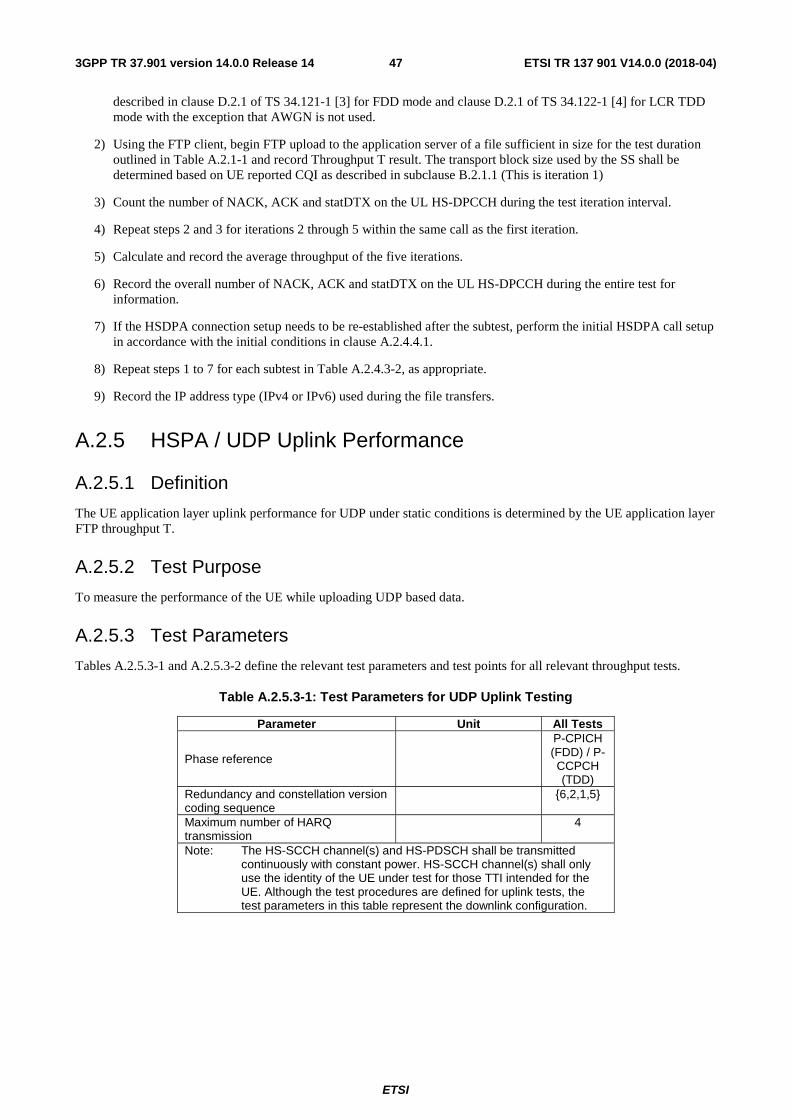
ETSI
ETSI TR 137 901 V14.0.0 (2018-04)473GPP TR 37.901 version 14.0.0 Release 14
described in clause D.2.1 of TS 34.121-1 [3] for FDD mode and clause D.2.1 of TS 34.122-1 [4] for LCR TDD mode with the exception that AWGN is not used.
2) Using the FTP client, begin FTP upload to the application server of a file sufficient in size for the test duration outlined in Table A.2.1-1 and record Throughput T result. The transport block size used by the SS shall be determined based on UE reported CQI as described in subclause B.2.1.1 (This is iteration 1)
3) Count the number of NACK, ACK and statDTX on the UL HS-DPCCH during the test iteration interval.
4) Repeat steps 2 and 3 for iterations 2 through 5 within the same call as the first iteration.
5) Calculate and record the average throughput of the five iterations.
6) Record the overall number of NACK, ACK and statDTX on the UL HS-DPCCH during the entire test for information.
7) If the HSDPA connection setup needs to be re-established after the subtest, perform the initial HSDPA call setup in accordance with the initial conditions in clause A.2.4.4.1.
8) Repeat steps 1 to 7 for each subtest in Table A.2.4.3-2, as appropriate.
9) Record the IP address type (IPv4 or IPv6) used during the file transfers.
A.2.5 HSPA / UDP Uplink Performance
A.2.5.1 Definition
The UE application layer uplink performance for UDP under static conditions is determined by the UE application layer FTP throughput T.
A.2.5.2 Test Purpose
To measure the performance of the UE while uploading UDP based data.
A.2.5.3 Test Parameters
Tables A.2.5.3-1 and A.2.5.3-2 define the relevant test parameters and test points for all relevant throughput tests.
Table A.2.5.3-1: Test Parameters for UDP Uplink Testing
Parameter Unit All Tests
Phase reference
P-CPICH (FDD) / P-CCPCH (TDD)
Redundancy and constellation version coding sequence {6,2,1,5}
Maximum number of HARQ transmission 4
Note: The HS-SCCH channel(s) and HS-PDSCH shall be transmitted continuously with constant power. HS-SCCH channel(s) shall only use the identity of the UE under test for those TTI intended for the UE. Although the test procedures are defined for uplink tests, the test parameters in this table represent the downlink configuration.
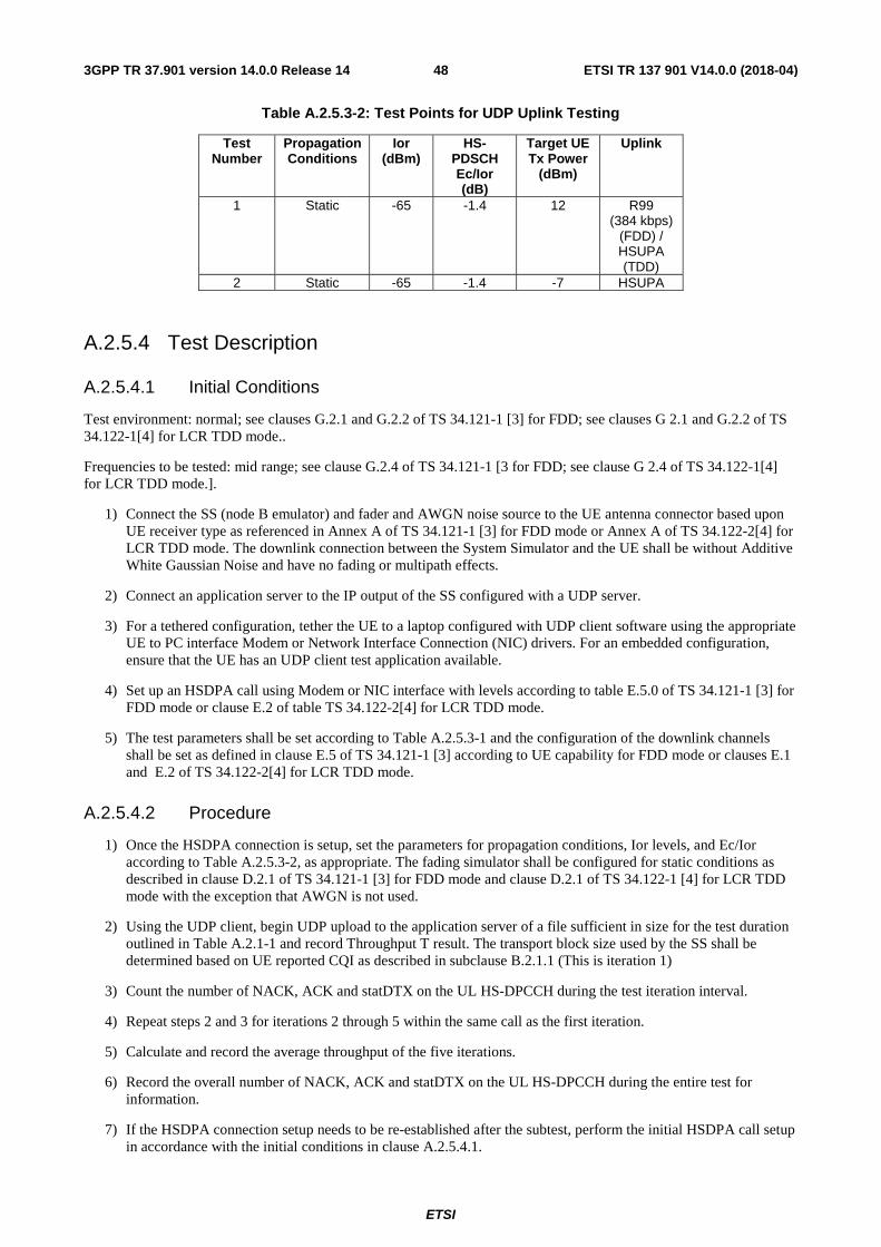
ETSI
ETSI TR 137 901 V14.0.0 (2018-04)483GPP TR 37.901 version 14.0.0 Release 14
Table A.2.5.3-2: Test Points for UDP Uplink Testing
Test Number
Propagation Conditions
Ior (dBm)
HS-PDSCH Ec/Ior (dB)
Target UE Tx Power
(dBm)
Uplink
1 Static -65 -1.4 12 R99 (384 kbps)
(FDD) / HSUPA (TDD)
2 Static -65 -1.4 -7 HSUPA
A.2.5.4 Test Description
A.2.5.4.1 Initial Conditions
Test environment: normal; see clauses G.2.1 and G.2.2 of TS 34.121-1 [3] for FDD; see clauses G 2.1 and G.2.2 of TS 34.122-1[4] for LCR TDD mode..
Frequencies to be tested: mid range; see clause G.2.4 of TS 34.121-1 [3 for FDD; see clause G 2.4 of TS 34.122-1[4] for LCR TDD mode.].
1) Connect the SS (node B emulator) and fader and AWGN noise source to the UE antenna connector based upon UE receiver type as referenced in Annex A of TS 34.121-1 [3] for FDD mode or Annex A of TS 34.122-2[4] for LCR TDD mode. The downlink connection between the System Simulator and the UE shall be without Additive White Gaussian Noise and have no fading or multipath effects.
2) Connect an application server to the IP output of the SS configured with a UDP server.
3) For a tethered configuration, tether the UE to a laptop configured with UDP client software using the appropriate UE to PC interface Modem or Network Interface Connection (NIC) drivers. For an embedded configuration, ensure that the UE has an UDP client test application available.
4) Set up an HSDPA call using Modem or NIC interface with levels according to table E.5.0 of TS 34.121-1 [3] for FDD mode or clause E.2 of table TS 34.122-2[4] for LCR TDD mode.
5) The test parameters shall be set according to Table A.2.5.3-1 and the configuration of the downlink channels shall be set as defined in clause E.5 of TS 34.121-1 [3] according to UE capability for FDD mode or clauses E.1 and E.2 of TS 34.122-2[4] for LCR TDD mode.
A.2.5.4.2 Procedure
1) Once the HSDPA connection is setup, set the parameters for propagation conditions, Ior levels, and Ec/Ior according to Table A.2.5.3-2, as appropriate. The fading simulator shall be configured for static conditions as described in clause D.2.1 of TS 34.121-1 [3] for FDD mode and clause D.2.1 of TS 34.122-1 [4] for LCR TDD mode with the exception that AWGN is not used.
2) Using the UDP client, begin UDP upload to the application server of a file sufficient in size for the test duration outlined in Table A.2.1-1 and record Throughput T result. The transport block size used by the SS shall be determined based on UE reported CQI as described in subclause B.2.1.1 (This is iteration 1)
3) Count the number of NACK, ACK and statDTX on the UL HS-DPCCH during the test iteration interval.
4) Repeat steps 2 and 3 for iterations 2 through 5 within the same call as the first iteration.
5) Calculate and record the average throughput of the five iterations.
6) Record the overall number of NACK, ACK and statDTX on the UL HS-DPCCH during the entire test for information.
7) If the HSDPA connection setup needs to be re-established after the subtest, perform the initial HSDPA call setup in accordance with the initial conditions in clause A.2.5.4.1.
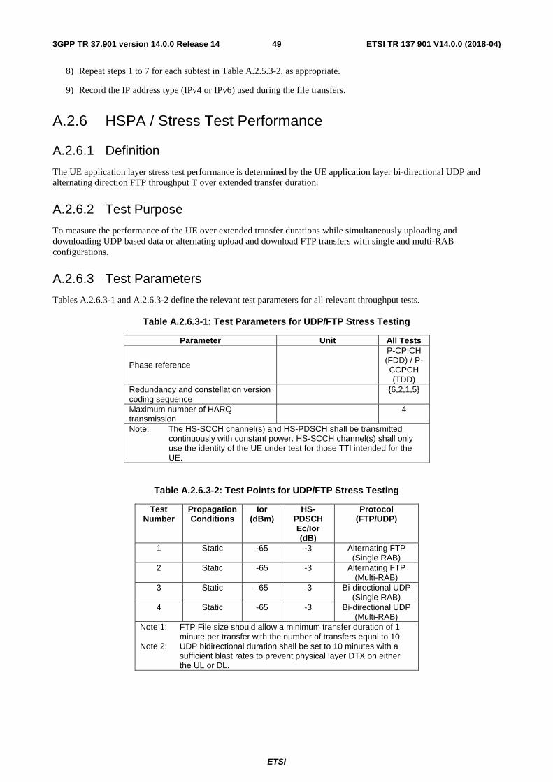
ETSI
ETSI TR 137 901 V14.0.0 (2018-04)493GPP TR 37.901 version 14.0.0 Release 14
8) Repeat steps 1 to 7 for each subtest in Table A.2.5.3-2, as appropriate.
9) Record the IP address type (IPv4 or IPv6) used during the file transfers.
A.2.6 HSPA / Stress Test Performance
A.2.6.1 Definition
The UE application layer stress test performance is determined by the UE application layer bi-directional UDP and alternating direction FTP throughput T over extended transfer duration.
A.2.6.2 Test Purpose
To measure the performance of the UE over extended transfer durations while simultaneously uploading and downloading UDP based data or alternating upload and download FTP transfers with single and multi-RAB configurations.
A.2.6.3 Test Parameters
Tables A.2.6.3-1 and A.2.6.3-2 define the relevant test parameters for all relevant throughput tests.
Table A.2.6.3-1: Test Parameters for UDP/FTP Stress Testing
Parameter Unit All Tests
Phase reference
P-CPICH (FDD) / P-CCPCH (TDD)
Redundancy and constellation version coding sequence
{6,2,1,5}
Maximum number of HARQ transmission 4
Note: The HS-SCCH channel(s) and HS-PDSCH shall be transmitted continuously with constant power. HS-SCCH channel(s) shall only use the identity of the UE under test for those TTI intended for the UE.
Table A.2.6.3-2: Test Points for UDP/FTP Stress Testing
Test Number
Propagation Conditions
Ior (dBm)
HS-PDSCH Ec/Ior (dB)
Protocol (FTP/UDP)
1 Static -65 -3 Alternating FTP (Single RAB)
2 Static -65 -3 Alternating FTP (Multi-RAB)
3 Static -65 -3 Bi-directional UDP (Single RAB)
4 Static -65 -3 Bi-directional UDP (Multi-RAB)
Note 1: FTP File size should allow a minimum transfer duration of 1 minute per transfer with the number of transfers equal to 10.
Note 2: UDP bidirectional duration shall be set to 10 minutes with a sufficient blast rates to prevent physical layer DTX on either the UL or DL.
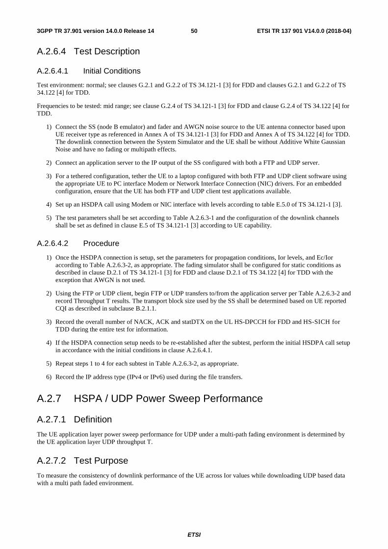
ETSI
ETSI TR 137 901 V14.0.0 (2018-04)503GPP TR 37.901 version 14.0.0 Release 14
A.2.6.4 Test Description
A.2.6.4.1 Initial Conditions
Test environment: normal; see clauses G.2.1 and G.2.2 of TS 34.121-1 [3] for FDD and clauses G.2.1 and G.2.2 of TS 34.122 [4] for TDD.
Frequencies to be tested: mid range; see clause G.2.4 of TS 34.121-1 [3] for FDD and clause G.2.4 of TS 34.122 [4] for TDD.
1) Connect the SS (node B emulator) and fader and AWGN noise source to the UE antenna connector based upon UE receiver type as referenced in Annex A of TS 34.121-1 [3] for FDD and Annex A of TS 34.122 [4] for TDD. The downlink connection between the System Simulator and the UE shall be without Additive White Gaussian Noise and have no fading or multipath effects.
2) Connect an application server to the IP output of the SS configured with both a FTP and UDP server.
3) For a tethered configuration, tether the UE to a laptop configured with both FTP and UDP client software using the appropriate UE to PC interface Modem or Network Interface Connection (NIC) drivers. For an embedded configuration, ensure that the UE has both FTP and UDP client test applications available.
4) Set up an HSDPA call using Modem or NIC interface with levels according to table E.5.0 of TS 34.121-1 [3].
5) The test parameters shall be set according to Table A.2.6.3-1 and the configuration of the downlink channels shall be set as defined in clause E.5 of TS 34.121-1 [3] according to UE capability.
A.2.6.4.2 Procedure
1) Once the HSDPA connection is setup, set the parameters for propagation conditions, Ior levels, and Ec/Ior according to Table A.2.6.3-2, as appropriate. The fading simulator shall be configured for static conditions as described in clause D.2.1 of TS 34.121-1 [3] for FDD and clause D.2.1 of TS 34.122 [4] for TDD with the exception that AWGN is not used.
2) Using the FTP or UDP client, begin FTP or UDP transfers to/from the application server per Table A.2.6.3-2 and record Throughput T results. The transport block size used by the SS shall be determined based on UE reported CQI as described in subclause B.2.1.1.
3) Record the overall number of NACK, ACK and statDTX on the UL HS-DPCCH for FDD and HS-SICH for TDD during the entire test for information.
4) If the HSDPA connection setup needs to be re-established after the subtest, perform the initial HSDPA call setup in accordance with the initial conditions in clause A.2.6.4.1.
5) Repeat steps 1 to 4 for each subtest in Table A.2.6.3-2, as appropriate.
6) Record the IP address type (IPv4 or IPv6) used during the file transfers.
A.2.7 HSPA / UDP Power Sweep Performance
A.2.7.1 Definition
The UE application layer power sweep performance for UDP under a multi-path fading environment is determined by the UE application layer UDP throughput T.
A.2.7.2 Test Purpose
To measure the consistency of downlink performance of the UE across Ior values while downloading UDP based data with a multi path faded environment.
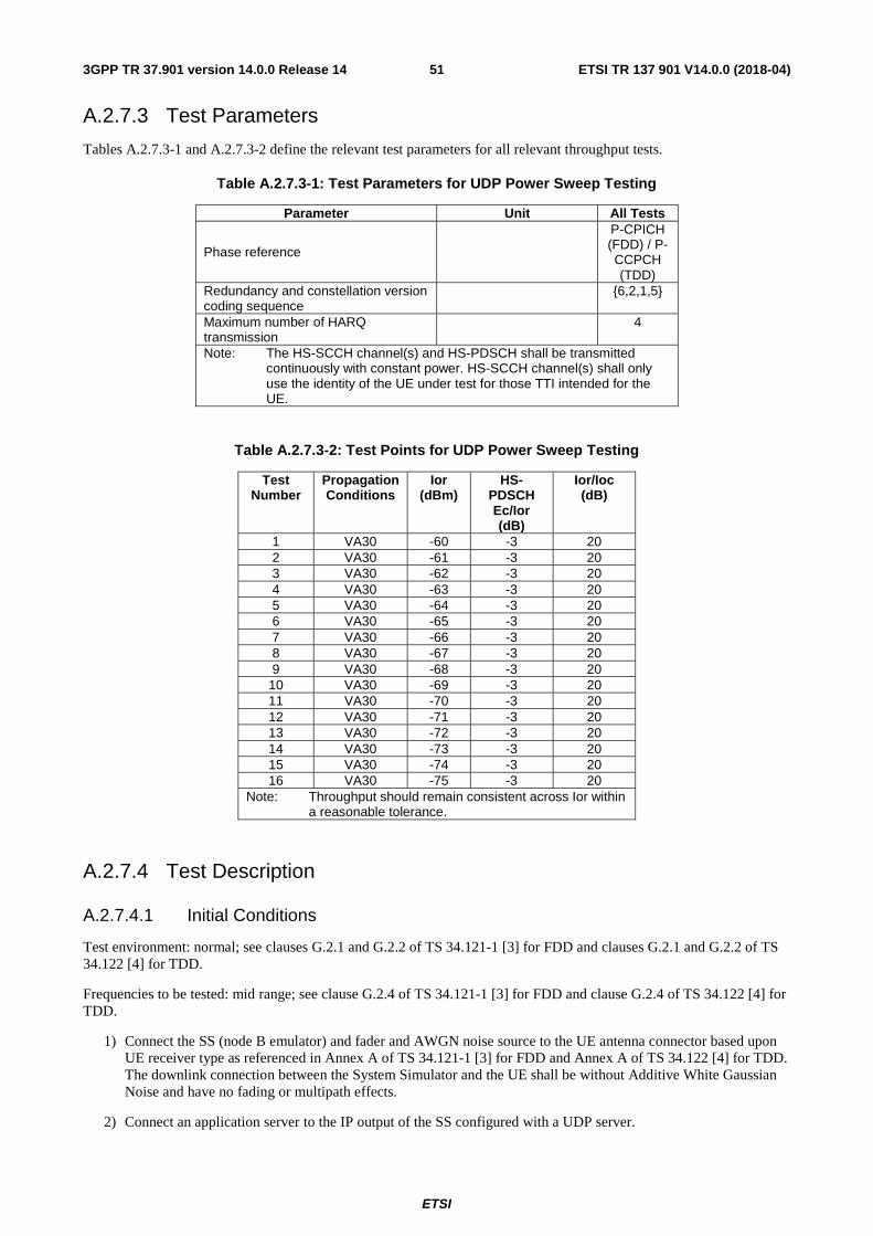
ETSI
ETSI TR 137 901 V14.0.0 (2018-04)513GPP TR 37.901 version 14.0.0 Release 14
A.2.7.3 Test Parameters
Tables A.2.7.3-1 and A.2.7.3-2 define the relevant test parameters for all relevant throughput tests.
Table A.2.7.3-1: Test Parameters for UDP Power Sweep Testing
Parameter Unit All Tests
Phase reference
P-CPICH (FDD) / P-CCPCH (TDD)
Redundancy and constellation version coding sequence {6,2,1,5}
Maximum number of HARQ transmission 4
Note: The HS-SCCH channel(s) and HS-PDSCH shall be transmitted continuously with constant power. HS-SCCH channel(s) shall only use the identity of the UE under test for those TTI intended for the UE.
Table A.2.7.3-2: Test Points for UDP Power Sweep Testing
Test Number
Propagation Conditions
Ior (dBm)
HS-PDSCH Ec/Ior (dB)
Ior/Ioc (dB)
1 VA30 -60 -3 20 2 VA30 -61 -3 20 3 VA30 -62 -3 20 4 VA30 -63 -3 20 5 VA30 -64 -3 20 6 VA30 -65 -3 20 7 VA30 -66 -3 20 8 VA30 -67 -3 20 9 VA30 -68 -3 20
10 VA30 -69 -3 20 11 VA30 -70 -3 20 12 VA30 -71 -3 20 13 VA30 -72 -3 20 14 VA30 -73 -3 20 15 VA30 -74 -3 20 16 VA30 -75 -3 20
Note: Throughput should remain consistent across Ior within a reasonable tolerance.
A.2.7.4 Test Description
A.2.7.4.1 Initial Conditions
Test environment: normal; see clauses G.2.1 and G.2.2 of TS 34.121-1 [3] for FDD and clauses G.2.1 and G.2.2 of TS 34.122 [4] for TDD.
Frequencies to be tested: mid range; see clause G.2.4 of TS 34.121-1 [3] for FDD and clause G.2.4 of TS 34.122 [4] for TDD.
1) Connect the SS (node B emulator) and fader and AWGN noise source to the UE antenna connector based upon UE receiver type as referenced in Annex A of TS 34.121-1 [3] for FDD and Annex A of TS 34.122 [4] for TDD. The downlink connection between the System Simulator and the UE shall be without Additive White Gaussian Noise and have no fading or multipath effects.
2) Connect an application server to the IP output of the SS configured with a UDP server.
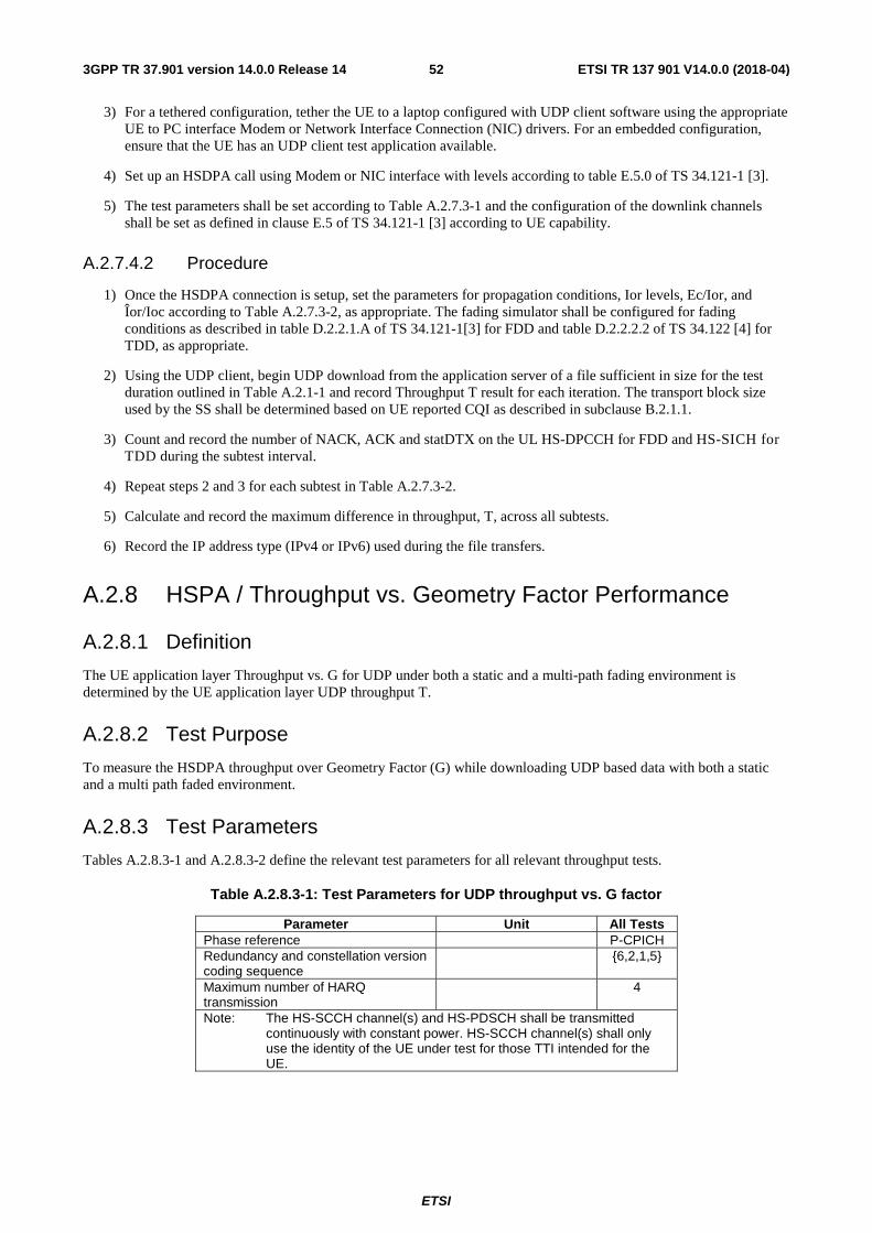
ETSI
ETSI TR 137 901 V14.0.0 (2018-04)523GPP TR 37.901 version 14.0.0 Release 14
3) For a tethered configuration, tether the UE to a laptop configured with UDP client software using the appropriate UE to PC interface Modem or Network Interface Connection (NIC) drivers. For an embedded configuration, ensure that the UE has an UDP client test application available.
4) Set up an HSDPA call using Modem or NIC interface with levels according to table E.5.0 of TS 34.121-1 [3].
5) The test parameters shall be set according to Table A.2.7.3-1 and the configuration of the downlink channels shall be set as defined in clause E.5 of TS 34.121-1 [3] according to UE capability.
A.2.7.4.2 Procedure
1) Once the HSDPA connection is setup, set the parameters for propagation conditions, Ior levels, Ec/Ior, and Îor/Ioc according to Table A.2.7.3-2, as appropriate. The fading simulator shall be configured for fading conditions as described in table D.2.2.1.A of TS 34.121-1[3] for FDD and table D.2.2.2.2 of TS 34.122 [4] for TDD, as appropriate.
2) Using the UDP client, begin UDP download from the application server of a file sufficient in size for the test duration outlined in Table A.2.1-1 and record Throughput T result for each iteration. The transport block size used by the SS shall be determined based on UE reported CQI as described in subclause B.2.1.1.
3) Count and record the number of NACK, ACK and statDTX on the UL HS-DPCCH for FDD and HS-SICH for TDD during the subtest interval.
4) Repeat steps 2 and 3 for each subtest in Table A.2.7.3-2.
5) Calculate and record the maximum difference in throughput, T, across all subtests.
6) Record the IP address type (IPv4 or IPv6) used during the file transfers.
A.2.8 HSPA / Throughput vs. Geometry Factor Performance
A.2.8.1 Definition
The UE application layer Throughput vs. G for UDP under both a static and a multi-path fading environment is determined by the UE application layer UDP throughput T.
A.2.8.2 Test Purpose
To measure the HSDPA throughput over Geometry Factor (G) while downloading UDP based data with both a static and a multi path faded environment.
A.2.8.3 Test Parameters
Tables A.2.8.3-1 and A.2.8.3-2 define the relevant test parameters for all relevant throughput tests.
Table A.2.8.3-1: Test Parameters for UDP throughput vs. G factor
Parameter Unit All Tests Phase reference P-CPICH Redundancy and constellation version coding sequence {6,2,1,5}
Maximum number of HARQ transmission 4
Note: The HS-SCCH channel(s) and HS-PDSCH shall be transmitted continuously with constant power. HS-SCCH channel(s) shall only use the identity of the UE under test for those TTI intended for the UE.
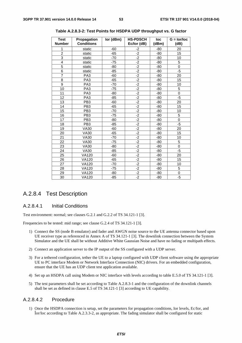
ETSI
ETSI TR 137 901 V14.0.0 (2018-04)533GPP TR 37.901 version 14.0.0 Release 14
Table A.2.8.3-2: Test Points for HSDPA UDP throughput vs. G factor
Test Number
Propagation Conditions
Ior (dBm) HS-PDSCH Ec/Ior (dB)
Ioc (dBm)
G = Ior/Ioc (dB)
1 static -60 -2 -80 20 2 static -65 -2 -80 15 3 static -70 -2 -80 10 4 static -75 -2 -80 5 5 static -80 -2 -80 0 6 static -85 -2 -80 -5 7 PA3 -60 -2 -80 20 8 PA3 -65 -2 -80 15 9 PA3 -70 -2 -80 10 10 PA3 -75 -2 -80 5 11 PA3 -80 -2 -80 0 12 PA3 -85 -2 -80 -5 13 PB3 -60 -2 -80 20 14 PB3 -65 -2 -80 15 15 PB3 -70 -2 -80 10 16 PB3 -75 -2 -80 5 17 PB3 -80 -2 -80 0 18 PB3 -85 -2 -80 -5 19 VA30 -60 -2 -80 20 20 VA30 -65 -2 -80 15 21 VA30 -70 -2 -80 10 22 VA30 -75 -2 -80 5 23 VA30 -80 -2 -80 0 24 VA30 -85 -2 -80 -5 25 VA120 -60 -2 -80 20 26 VA120 -65 -2 -80 15 27 VA120 -70 -2 -80 10 28 VA120 -75 -2 -80 5 29 VA120 -80 -2 -80 0 30 VA120 -85 -2 -80 -5
A.2.8.4 Test Description
A.2.8.4.1 Initial Conditions
Test environment: normal; see clauses G.2.1 and G.2.2 of TS 34.121-1 [3].
Frequencies to be tested: mid range; see clause G.2.4 of TS 34.121-1 [3].
1) Connect the SS (node B emulator) and fader and AWGN noise source to the UE antenna connector based upon UE receiver type as referenced in Annex A of TS 34.121-1 [3]. The downlink connection between the System Simulator and the UE shall be without Additive White Gaussian Noise and have no fading or multipath effects.
2) Connect an application server to the IP output of the SS configured with a UDP server.
3) For a tethered configuration, tether the UE to a laptop configured with UDP client software using the appropriate UE to PC interface Modem or Network Interface Connection (NIC) drivers. For an embedded configuration, ensure that the UE has an UDP client test application available.
4) Set up an HSDPA call using Modem or NIC interface with levels according to table E.5.0 of TS 34.121-1 [3].
5) The test parameters shall be set according to Table A.2.8.3-1 and the configuration of the downlink channels shall be set as defined in clause E.5 of TS 34.121-1 [3] according to UE capability.
A.2.8.4.2 Procedure
1) Once the HSDPA connection is setup, set the parameters for propagation conditions, Ior levels, Ec/Ior, and Îor/Ioc according to Table A.2.3.3-2, as appropriate. The fading simulator shall be configured for static
ETSI
ETSI TR 137 901 V14.0.0 (2018-04)543GPP TR 37.901 version 14.0.0 Release 14
conditions as described in clause D.2.1 of TS 34.121-1 [3] or for fading conditions as described in table D.2.2.1.A of TS 34.121-1[3], as appropriate.
2) Using the UDP client, begin UDP download from the application server of a file sufficient in size for the test duration outlined in Table A.2.1-1 and record Throughput T result. The transport block size used by the SS shall be determined based on UE reported CQI as described in subclause B.2.1.1.
3) Count the number of NACK, ACK and statDTX on the UL HS-DPCCH during the subtest interval.
4) Repeat steps 2 and 3 for each subtest in Table A.2.8.3-2.
5) Record the overall number of NACK, ACK and statDTX on the UL HS-DPCCH during the entire test for information.
6) If the HSDPA connection setup needs to be re-established after the subtest, perform the initial HSDPA call setup in accordance with the initial conditions in clause A.2.8.4.1.
7) Record the IP address type (IPv4 or IPv6) used during the file transfers.
A.3 UE Application Layer Data Throughput Performance Test Procedures for LTE
Editor’s Note: The following aspects are either missing or not yet determined:
- 4X2 MIMO aspects will be considered for a future release.
- To allow for test system implementation based on the clarifications applied in Notes 3 and 4 in the test parameter tables for the downlink performance tests in A.3.2 and A.3.3, the existing functionality based on TR 37.901 v11.10.0 may be used until RAN5 #65.
A.3.1 General The following test procedures will evaluate the UE Application Layer Data Throughput Performance for LTE.
For a tethered data configuration, the UE will be tethered to a laptop using the appropriate UE to PC interface Modem or Network Interface Connection (NIC) drivers as recommended by the UE manufacturer for the intended use by the customer/user. In most cases, a laptop with an embedded modem is considered to be a tethered data configuration as opposed to an embedded data configuration due to the UE to PC interface. Refer to the Tethered Data connection diagram in figure C.2.1-1.
For an embedded data configuration, the UE will be the endpoint of the measurement and will have the appropriate data client test applications called out in the test procedures. Refer to the Embedded Data connection diagram in figure C.2.2-1.
The UE should be tested in any data configuration that it supports (tethered and/or embedded).
The propagation conditions are specified in Annex B of TS 36.521-1 [2] and the Down link Physical channels are specified in Annex C TS 36.521-1 [2]. Unless stated otherwise, DL power control is OFF.
The common RF test conditions of Performance requirements are defined in clause A.3 of TS 36.521-1 [2], and each test conditions in clause 9 should refer to clause A.5 of TS 36.521-1 [2]. Individual test conditions are defined in the paragraph of each test.
All throughput measurements in Annex A.3 shall be performed according to the following general rules:
- The measured UE Application Layer Throughput, T, is defined in clause 5.1.2.
- Minimum test time is necessary for both static and multipath fading profiles to ensure stabilization of the FTP or UDP Application throughput. The following table provides statistical accuracy and simplifies the process by breaking it down into Static and faded profiles where the faded profile duration is sufficient for all faded standard fade models.
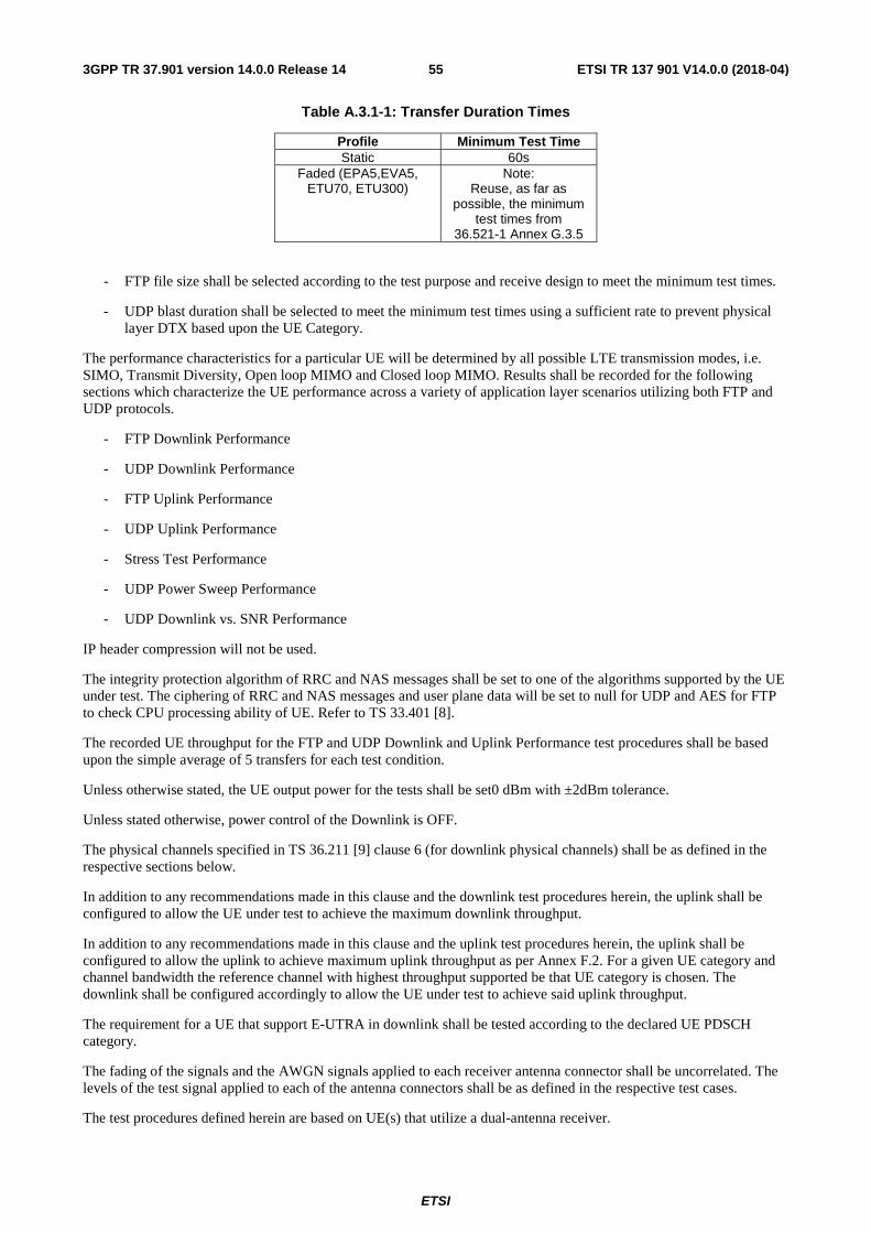
ETSI
ETSI TR 137 901 V14.0.0 (2018-04)553GPP TR 37.901 version 14.0.0 Release 14
Table A.3.1-1: Transfer Duration Times
Profile Minimum Test Time Static 60s
Faded (EPA5,EVA5, ETU70, ETU300)
Note: Reuse, as far as
possible, the minimum test times from
36.521-1 Annex G.3.5
- FTP file size shall be selected according to the test purpose and receive design to meet the minimum test times.
- UDP blast duration shall be selected to meet the minimum test times using a sufficient rate to prevent physical layer DTX based upon the UE Category.
The performance characteristics for a particular UE will be determined by all possible LTE transmission modes, i.e. SIMO, Transmit Diversity, Open loop MIMO and Closed loop MIMO. Results shall be recorded for the following sections which characterize the UE performance across a variety of application layer scenarios utilizing both FTP and UDP protocols.
- FTP Downlink Performance
- UDP Downlink Performance
- FTP Uplink Performance
- UDP Uplink Performance
- Stress Test Performance
- UDP Power Sweep Performance
- UDP Downlink vs. SNR Performance
IP header compression will not be used.
The integrity protection algorithm of RRC and NAS messages shall be set to one of the algorithms supported by the UE under test. The ciphering of RRC and NAS messages and user plane data will be set to null for UDP and AES for FTP to check CPU processing ability of UE. Refer to TS 33.401 [8].
The recorded UE throughput for the FTP and UDP Downlink and Uplink Performance test procedures shall be based upon the simple average of 5 transfers for each test condition.
Unless otherwise stated, the UE output power for the tests shall be set0 dBm with ±2dBm tolerance.
Unless stated otherwise, power control of the Downlink is OFF.
The physical channels specified in TS 36.211 [9] clause 6 (for downlink physical channels) shall be as defined in the respective sections below.
In addition to any recommendations made in this clause and the downlink test procedures herein, the uplink shall be configured to allow the UE under test to achieve the maximum downlink throughput.
In addition to any recommendations made in this clause and the uplink test procedures herein, the uplink shall be configured to allow the uplink to achieve maximum uplink throughput as per Annex F.2. For a given UE category and channel bandwidth the reference channel with highest throughput supported be that UE category is chosen. The downlink shall be configured accordingly to allow the UE under test to achieve said uplink throughput.
The requirement for a UE that support E-UTRA in downlink shall be tested according to the declared UE PDSCH category.
The fading of the signals and the AWGN signals applied to each receiver antenna connector shall be uncorrelated. The levels of the test signal applied to each of the antenna connectors shall be as defined in the respective test cases.
The test procedures defined herein are based on UE(s) that utilize a dual-antenna receiver.
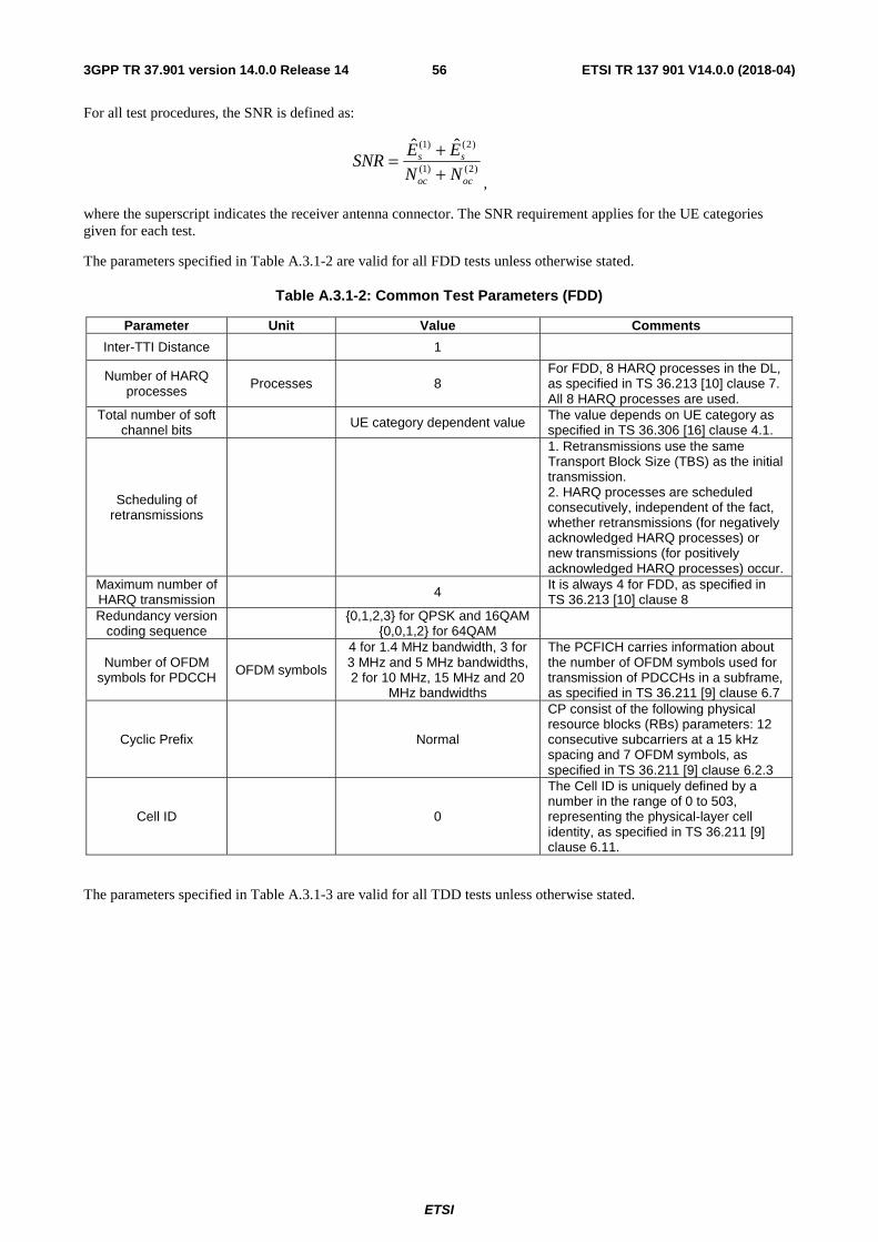
ETSI
ETSI TR 137 901 V14.0.0 (2018-04)563GPP TR 37.901 version 14.0.0 Release 14
For all test procedures, the SNR is defined as:
,
where the superscript indicates the receiver antenna connector. The SNR requirement applies for the UE categories given for each test.
The parameters specified in Table A.3.1-2 are valid for all FDD tests unless otherwise stated.
Table A.3.1-2: Common Test Parameters (FDD)
Parameter Unit Value Comments
Inter-TTI Distance 1
Number of HARQ processes
Processes 8 For FDD, 8 HARQ processes in the DL, as specified in TS 36.213 [10] clause 7. All 8 HARQ processes are used.
Total number of soft channel bits UE category dependent value The value depends on UE category as
specified in TS 36.306 [16] clause 4.1.
Scheduling of retransmissions
1. Retransmissions use the same Transport Block Size (TBS) as the initial transmission. 2. HARQ processes are scheduled consecutively, independent of the fact, whether retransmissions (for negatively acknowledged HARQ processes) or new transmissions (for positively acknowledged HARQ processes) occur.
Maximum number of HARQ transmission
4 It is always 4 for FDD, as specified in TS 36.213 [10] clause 8
Redundancy version coding sequence {0,1,2,3} for QPSK and 16QAM
{0,0,1,2} for 64QAM
Number of OFDM symbols for PDCCH OFDM symbols
4 for 1.4 MHz bandwidth, 3 for 3 MHz and 5 MHz bandwidths, 2 for 10 MHz, 15 MHz and 20
MHz bandwidths
The PCFICH carries information about the number of OFDM symbols used for transmission of PDCCHs in a subframe, as specified in TS 36.211 [9] clause 6.7
Cyclic Prefix Normal
CP consist of the following physical resource blocks (RBs) parameters: 12 consecutive subcarriers at a 15 kHz spacing and 7 OFDM symbols, as specified in TS 36.211 [9] clause 6.2.3
Cell ID 0
The Cell ID is uniquely defined by a number in the range of 0 to 503, representing the physical-layer cell identity, as specified in TS 36.211 [9] clause 6.11.
The parameters specified in Table A.3.1-3 are valid for all TDD tests unless otherwise stated.
)2()1(
)2()1( ˆˆ
ococ
ss
NN
EESNR
++=
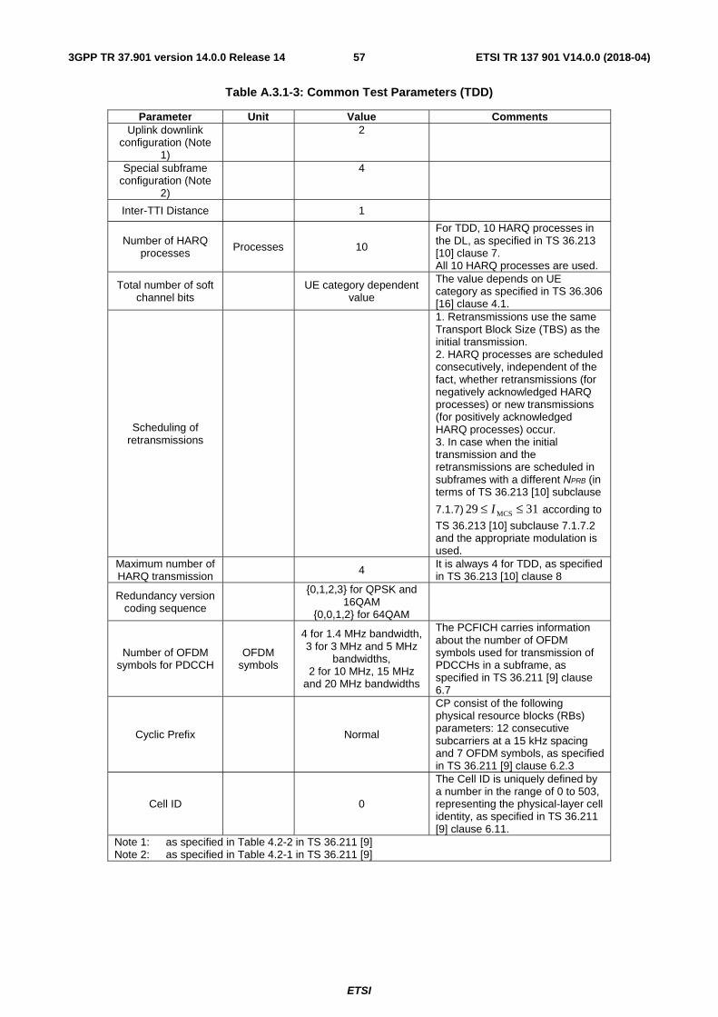
ETSI
ETSI TR 137 901 V14.0.0 (2018-04)573GPP TR 37.901 version 14.0.0 Release 14
Table A.3.1-3: Common Test Parameters (TDD)
Parameter Unit Value Comments Uplink downlink
configuration (Note 1)
2
Special subframe configuration (Note
2)
4
Inter-TTI Distance 1
Number of HARQ processes Processes 10
For TDD, 10 HARQ processes in the DL, as specified in TS 36.213 [10] clause 7. All 10 HARQ processes are used.
Total number of soft channel bits UE category dependent
value
The value depends on UE category as specified in TS 36.306 [16] clause 4.1.
Scheduling of retransmissions
1. Retransmissions use the same Transport Block Size (TBS) as the initial transmission. 2. HARQ processes are scheduled consecutively, independent of the fact, whether retransmissions (for negatively acknowledged HARQ processes) or new transmissions (for positively acknowledged HARQ processes) occur. 3. In case when the initial transmission and the retransmissions are scheduled in subframes with a different NPRB (in terms of TS 36.213 [10] subclause
7.1.7) 3129 MCS ≤≤ I according to
TS 36.213 [10] subclause 7.1.7.2 and the appropriate modulation is used.
Maximum number of HARQ transmission
4 It is always 4 for TDD, as specified in TS 36.213 [10] clause 8
Redundancy version coding sequence
{0,1,2,3} for QPSK and 16QAM
{0,0,1,2} for 64QAM
Number of OFDM symbols for PDCCH
OFDM symbols
4 for 1.4 MHz bandwidth, 3 for 3 MHz and 5 MHz
bandwidths, 2 for 10 MHz, 15 MHz
and 20 MHz bandwidths
The PCFICH carries information about the number of OFDM symbols used for transmission of PDCCHs in a subframe, as specified in TS 36.211 [9] clause 6.7
Cyclic Prefix Normal
CP consist of the following physical resource blocks (RBs) parameters: 12 consecutive subcarriers at a 15 kHz spacing and 7 OFDM symbols, as specified in TS 36.211 [9] clause 6.2.3
Cell ID 0
The Cell ID is uniquely defined by a number in the range of 0 to 503, representing the physical-layer cell identity, as specified in TS 36.211 [9] clause 6.11.
Note 1: as specified in Table 4.2-2 in TS 36.211 [9] Note 2: as specified in Table 4.2-1 in TS 36.211 [9]
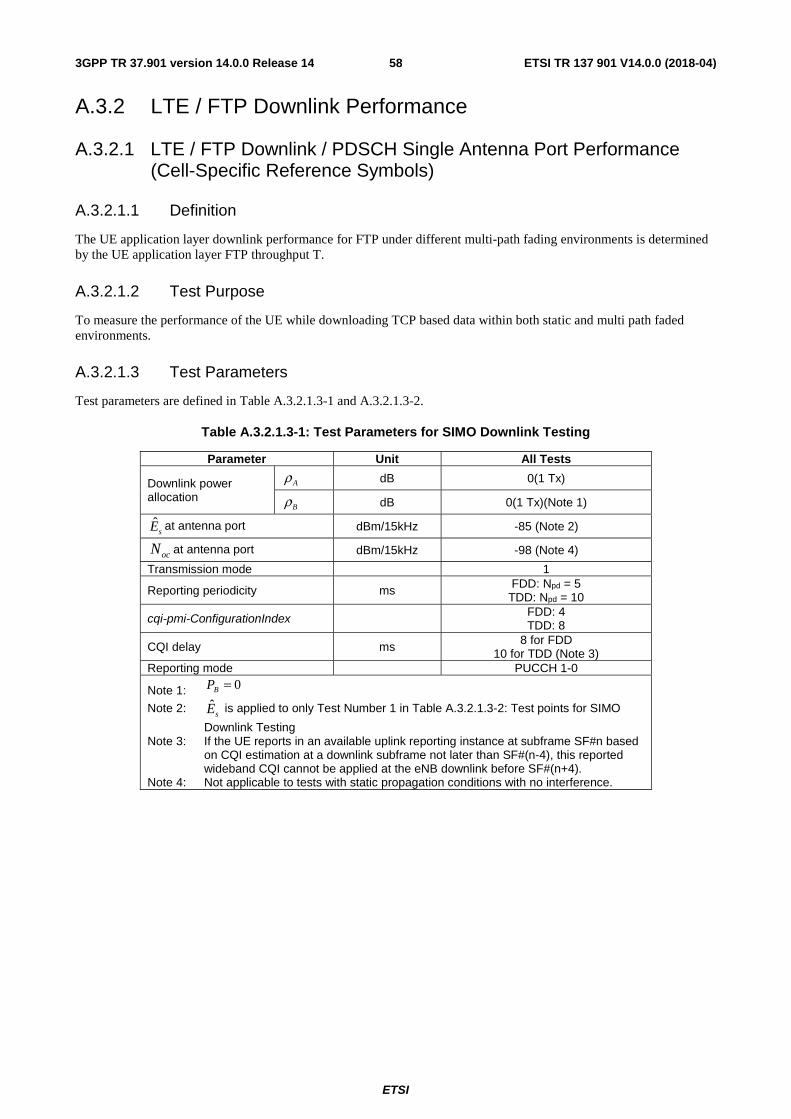
ETSI
ETSI TR 137 901 V14.0.0 (2018-04)583GPP TR 37.901 version 14.0.0 Release 14
A.3.2 LTE / FTP Downlink Performance
A.3.2.1 LTE / FTP Downlink / PDSCH Single Antenna Port Performance (Cell-Specific Reference Symbols)
A.3.2.1.1 Definition
The UE application layer downlink performance for FTP under different multi-path fading environments is determined by the UE application layer FTP throughput T.
A.3.2.1.2 Test Purpose
To measure the performance of the UE while downloading TCP based data within both static and multi path faded environments.
A.3.2.1.3 Test Parameters
Test parameters are defined in Table A.3.2.1.3-1 and A.3.2.1.3-2.
Table A.3.2.1.3-1: Test Parameters for SIMO Downlink Testing
Parameter Unit All Tests
Downlink power allocation
dB 0(1 Tx)
dB 0(1 Tx)(Note 1)
sE at antenna port
dBm/15kHz -85 (Note 2)
at antenna port dBm/15kHz -98 (Note 4)
Transmission mode
1
Reporting periodicity ms FDD: Npd = 5 TDD: Npd = 10
cqi-pmi-ConfigurationIndex FDD: 4 TDD: 8
CQI delay
ms 8 for FDD 10 for TDD (Note 3)
Reporting mode
PUCCH 1-0
Note 1:
Note 2: sE is applied to only Test Number 1 in Table A.3.2.1.3-2: Test points for SIMO
Downlink Testing Note 3: If the UE reports in an available uplink reporting instance at subframe SF#n based
on CQI estimation at a downlink subframe not later than SF#(n-4), this reported wideband CQI cannot be applied at the eNB downlink before SF#(n+4).
Note 4: Not applicable to tests with static propagation conditions with no interference.
Aρ
Bρ
ocN
0=BP
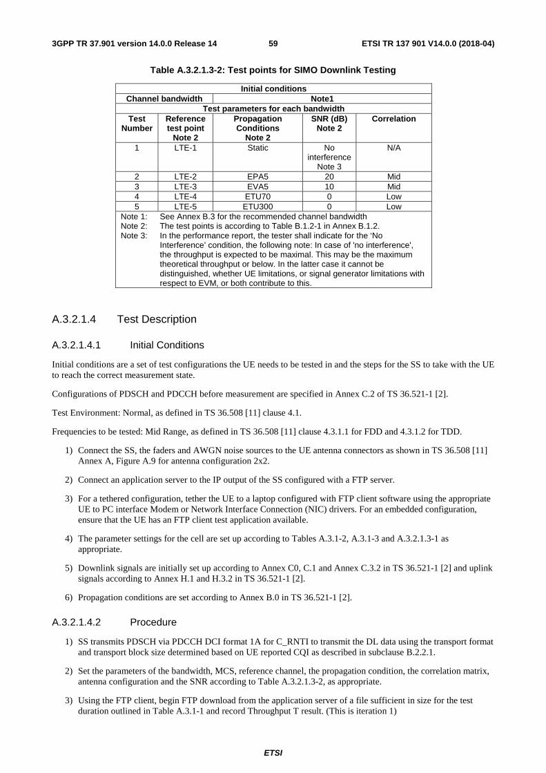
ETSI
ETSI TR 137 901 V14.0.0 (2018-04)593GPP TR 37.901 version 14.0.0 Release 14
Table A.3.2.1.3-2: Test points for SIMO Downlink Testing
Initial conditions Channel bandwidth Note1
Test parameters for each bandwidth Test
Number Reference test point
Note 2
Propagation Conditions
Note 2
SNR (dB) Note 2
Correlation
1 LTE-1 Static No interference
Note 3
N/A
2 LTE-2 EPA5 20 Mid 3 LTE-3 EVA5 10 Mid 4 LTE-4 ETU70 0 Low 5 LTE-5 ETU300 0 Low
Note 1: See Annex B.3 for the recommended channel bandwidth Note 2: The test points is according to Table B.1.2-1 in Annex B.1.2. Note 3: In the performance report, the tester shall indicate for the ‘No
Interference’ condition, the following note: In case of 'no interference', the throughput is expected to be maximal. This may be the maximum theoretical throughput or below. In the latter case it cannot be distinguished, whether UE limitations, or signal generator limitations with respect to EVM, or both contribute to this.
A.3.2.1.4 Test Description
A.3.2.1.4.1 Initial Conditions
Initial conditions are a set of test configurations the UE needs to be tested in and the steps for the SS to take with the UE to reach the correct measurement state.
Configurations of PDSCH and PDCCH before measurement are specified in Annex C.2 of TS 36.521-1 [2].
Test Environment: Normal, as defined in TS 36.508 [11] clause 4.1.
Frequencies to be tested: Mid Range, as defined in TS 36.508 [11] clause 4.3.1.1 for FDD and 4.3.1.2 for TDD.
1) Connect the SS, the faders and AWGN noise sources to the UE antenna connectors as shown in TS 36.508 [11] Annex A, Figure A.9 for antenna configuration 2x2.
2) Connect an application server to the IP output of the SS configured with a FTP server.
3) For a tethered configuration, tether the UE to a laptop configured with FTP client software using the appropriate UE to PC interface Modem or Network Interface Connection (NIC) drivers. For an embedded configuration, ensure that the UE has an FTP client test application available.
4) The parameter settings for the cell are set up according to Tables A.3.1-2, A.3.1-3 and A.3.2.1.3-1 as appropriate.
5) Downlink signals are initially set up according to Annex C0, C.1 and Annex C.3.2 in TS 36.521-1 [2] and uplink signals according to Annex H.1 and H.3.2 in TS 36.521-1 [2].
6) Propagation conditions are set according to Annex B.0 in TS 36.521-1 [2].
A.3.2.1.4.2 Procedure
1) SS transmits PDSCH via PDCCH DCI format 1A for C_RNTI to transmit the DL data using the transport format and transport block size determined based on UE reported CQI as described in subclause B.2.2.1.
2) Set the parameters of the bandwidth, MCS, reference channel, the propagation condition, the correlation matrix, antenna configuration and the SNR according to Table A.3.2.1.3-2, as appropriate.
3) Using the FTP client, begin FTP download from the application server of a file sufficient in size for the test duration outlined in Table A.3.1-1 and record Throughput T result. (This is iteration 1)
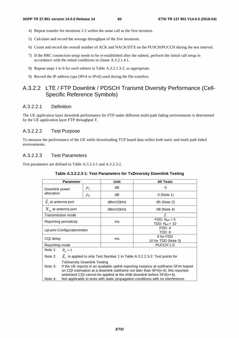
ETSI
ETSI TR 137 901 V14.0.0 (2018-04)603GPP TR 37.901 version 14.0.0 Release 14
4) Repeat transfer for iterations 2-5 within the same call as the first iteration.
5) Calculate and record the average throughput of the five iterations.
6) Count and record the overall number of ACK and NACK/DTX on the PUSCH/PUCCH during the test interval.
7) If the RRC connection setup needs to be re-established after the subtest, perform the initial call setup in accordance with the initial conditions in clause A.3.2.1.4.1.
8) Repeat steps 1 to 6 for each subtest in Table A.3.2.1.3-2, as appropriate.
9) Record the IP address type (IPv4 or IPv6) used during the file transfers.
A.3.2.2 LTE / FTP Downlink / PDSCH Transmit Diversity Performance (Cell-Specific Reference Symbols)
A.3.2.2.1 Definition
The UE application layer downlink performance for FTP under different multi-path fading environments is determined by the UE application layer FTP throughput T.
A.3.2.2.2 Test Purpose
To measure the performance of the UE while downloading TCP based data within both static and multi path faded environments.
A.3.2.2.3 Test Parameters
Test parameters are defined in Table A.3.2.3-1 and A.3.2.3-2.
Table A.3.2.2.3-1: Test Parameters for TxDiversity Downlink Testing
Parameter Unit All Tests
Downlink power allocation
dB -3
dB -3 (Note 1)
sE at antenna port
dBm/15kHz -85 (Note 2)
at antenna port dBm/15kHz -98 (Note 4)
Transmission mode
2
Reporting periodicity ms FDD: Npd = 5 TDD: Npd = 10
cqi-pmi-ConfigurationIndex FDD: 4 TDD: 8
CQI delay
ms 8 for FDD 10 for TDD (Note 3)
Reporting mode
PUCCH 1-0 Note 1: Note 2: sE is applied to only Test Number 1 in Table A.3.2.2.3-2: Test points for
TxDiversity Downlink Testing Note 3: If the UE reports in an available uplink reporting instance at subframe SF#n based
on CQI estimation at a downlink subframe not later than SF#(n-4), this reported wideband CQI cannot be applied at the eNB downlink before SF#(n+4).
Note 4: Not applicable to tests with static propagation conditions with no interference.
Aρ
Bρ
ocN
1=BP
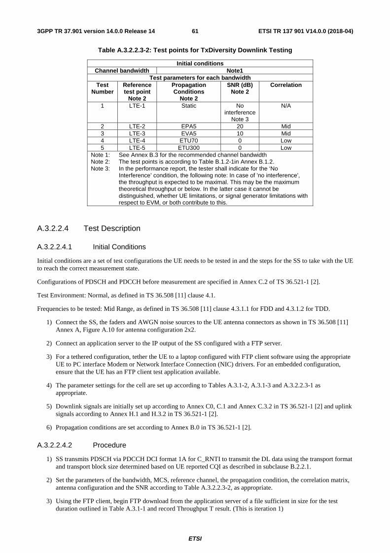
ETSI
ETSI TR 137 901 V14.0.0 (2018-04)613GPP TR 37.901 version 14.0.0 Release 14
Table A.3.2.2.3-2: Test points for TxDiversity Downlink Testing
Initial conditions Channel bandwidth Note1
Test parameters for each bandwidth Test
Number Reference test point
Note 2
Propagation Conditions
Note 2
SNR (dB) Note 2
Correlation
1 LTE-1 Static No interference
Note 3
N/A
2 LTE-2 EPA5 20 Mid 3 LTE-3 EVA5 10 Mid 4 LTE-4 ETU70 0 Low 5 LTE-5 ETU300 0 Low
Note 1: See Annex B.3 for the recommended channel bandwidth Note 2: The test points is according to Table B.1.2-1in Annex B.1.2. Note 3: In the performance report, the tester shall indicate for the ‘No
Interference’ condition, the following note: In case of 'no interference', the throughput is expected to be maximal. This may be the maximum theoretical throughput or below. In the latter case it cannot be distinguished, whether UE limitations, or signal generator limitations with respect to EVM, or both contribute to this.
A.3.2.2.4 Test Description
A.3.2.2.4.1 Initial Conditions
Initial conditions are a set of test configurations the UE needs to be tested in and the steps for the SS to take with the UE to reach the correct measurement state.
Configurations of PDSCH and PDCCH before measurement are specified in Annex C.2 of TS 36.521-1 [2].
Test Environment: Normal, as defined in TS 36.508 [11] clause 4.1.
Frequencies to be tested: Mid Range, as defined in TS 36.508 [11] clause 4.3.1.1 for FDD and 4.3.1.2 for TDD.
1) Connect the SS, the faders and AWGN noise sources to the UE antenna connectors as shown in TS 36.508 [11] Annex A, Figure A.10 for antenna configuration 2x2.
2) Connect an application server to the IP output of the SS configured with a FTP server.
3) For a tethered configuration, tether the UE to a laptop configured with FTP client software using the appropriate UE to PC interface Modem or Network Interface Connection (NIC) drivers. For an embedded configuration, ensure that the UE has an FTP client test application available.
4) The parameter settings for the cell are set up according to Tables A.3.1-2, A.3.1-3 and A.3.2.2.3-1 as appropriate.
5) Downlink signals are initially set up according to Annex C0, C.1 and Annex C.3.2 in TS 36.521-1 [2] and uplink signals according to Annex H.1 and H.3.2 in TS 36.521-1 [2].
6) Propagation conditions are set according to Annex B.0 in TS 36.521-1 [2].
A.3.2.2.4.2 Procedure
1) SS transmits PDSCH via PDCCH DCI format 1A for C_RNTI to transmit the DL data using the transport format and transport block size determined based on UE reported CQI as described in subclause B.2.2.1.
2) Set the parameters of the bandwidth, MCS, reference channel, the propagation condition, the correlation matrix, antenna configuration and the SNR according to Table A.3.2.2.3-2, as appropriate.
3) Using the FTP client, begin FTP download from the application server of a file sufficient in size for the test duration outlined in Table A.3.1-1 and record Throughput T result. (This is iteration 1)
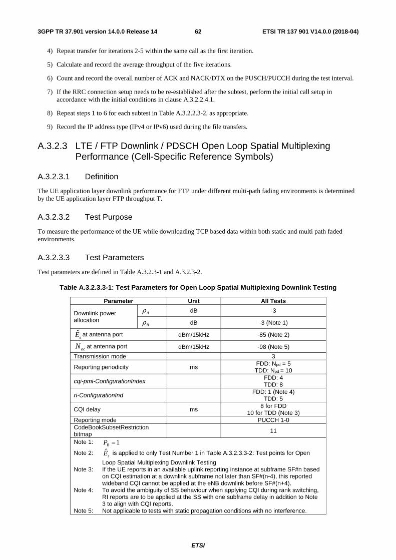
ETSI
ETSI TR 137 901 V14.0.0 (2018-04)623GPP TR 37.901 version 14.0.0 Release 14
4) Repeat transfer for iterations 2-5 within the same call as the first iteration.
5) Calculate and record the average throughput of the five iterations.
6) Count and record the overall number of ACK and NACK/DTX on the PUSCH/PUCCH during the test interval.
7) If the RRC connection setup needs to be re-established after the subtest, perform the initial call setup in accordance with the initial conditions in clause A.3.2.2.4.1.
8) Repeat steps 1 to 6 for each subtest in Table A.3.2.2.3-2, as appropriate.
9) Record the IP address type (IPv4 or IPv6) used during the file transfers.
A.3.2.3 LTE / FTP Downlink / PDSCH Open Loop Spatial Multiplexing Performance (Cell-Specific Reference Symbols)
A.3.2.3.1 Definition
The UE application layer downlink performance for FTP under different multi-path fading environments is determined by the UE application layer FTP throughput T.
A.3.2.3.2 Test Purpose
To measure the performance of the UE while downloading TCP based data within both static and multi path faded environments.
A.3.2.3.3 Test Parameters
Test parameters are defined in Table A.3.2.3-1 and A.3.2.3-2.
Table A.3.2.3.3-1: Test Parameters for Open Loop Spatial Multiplexing Downlink Testing
Parameter Unit All Tests
Downlink power allocation
dB -3
dB -3 (Note 1)
sE at antenna port
dBm/15kHz -85 (Note 2)
at antenna port dBm/15kHz -98 (Note 5)
Transmission mode
3
Reporting periodicity ms FDD: Npd = 5 TDD: Npd = 10
cqi-pmi-ConfigurationIndex FDD: 4 TDD: 8
ri-ConfigurationInd FDD: 1 (Note 4) TDD: 5
CQI delay
ms 8 for FDD 10 for TDD (Note 3)
Reporting mode
PUCCH 1-0 CodeBookSubsetRestriction bitmap 11
Note 1: Note 2: sE is applied to only Test Number 1 in Table A.3.2.3.3-2: Test points for Open
Loop Spatial Multiplexing Downlink Testing Note 3: If the UE reports in an available uplink reporting instance at subframe SF#n based
on CQI estimation at a downlink subframe not later than SF#(n-4), this reported wideband CQI cannot be applied at the eNB downlink before SF#(n+4).
Note 4: To avoid the ambiguity of SS behaviour when applying CQI during rank switching, RI reports are to be applied at the SS with one subframe delay in addition to Note 3 to align with CQI reports.
Note 5: Not applicable to tests with static propagation conditions with no interference.
Aρ
Bρ
ocN
1=BP

ETSI
ETSI TR 137 901 V14.0.0 (2018-04)633GPP TR 37.901 version 14.0.0 Release 14
Table A.3.2.3.3-2: Test points for Open Loop Spatial Multiplexing Downlink Testing
Initial conditions Channel bandwidth Note1
Test parameters for each bandwidth Test
Number Reference test point
Note 2
Propagation Conditions
Note 2
SNR (dB) Note 2
Correlation
1 LTE-1 Static No interference
Note 3
N/A
2 LTE-2 EPA5 20 Low 3 LTE-3 EVA5 10 Low 4 LTE-4 ETU70 0 Low 5 LTE-5 ETU300 0 Low
Note 1: See Annex B.3 for the recommended channel bandwidth Note 2: The test points is according to Table B.1.2-1in Annex B.1.2. Note 3: In the performance report, the tester shall indicate for the ‘No
Interference’ condition, the following note: In case of 'no interference', the throughput is expected to be maximal. This may be the maximum theoretical throughput or below. In the latter case it cannot be distinguished, whether UE limitations, or signal generator limitations with respect to EVM, or both contribute to this.
A.3.2.3.4 Test Description
A.3.2.3.4.1 Initial Conditions
Initial conditions are a set of test configurations the UE needs to be tested in and the steps for the SS to take with the UE to reach the correct measurement state.
Configurations of PDSCH and PDCCH before measurement are specified in Annex C.2 of TS 36.521-1 [2].
Test Environment: Normal, as defined in TS 36.508 [11] clause 4.1.
Frequencies to be tested: Mid Range, as defined in TS 36.508 [11] clause 4.3.1.1 for FDD and 4.3.1.2 for TDD.
1) Connect the SS, the faders and AWGN noise sources to the UE antenna connectors as shown in TS 36.508 [11] Annex A, Figure A.10 for antenna configuration 2x2.
2) Connect an application server to the IP output of the SS configured with a FTP server.
3) For a tethered configuration, tether the UE to a laptop configured with FTP client software using the appropriate UE to PC interface Modem or Network Interface Connection (NIC) drivers. For an embedded configuration, ensure that the UE has an FTP client test application available.
4) The parameter settings for the cell are set up according to Tables A.3.1-2, A.3.1-3 and A.3.2.3.3-1 as appropriate.
5) Downlink signals are initially set up according to Annex C0, C.1 and Annex C.3.2 in TS 36.521-1 [2] and uplink signals according to Annex H.1 and H.3.2 in TS 36.521-1 [2].
6) Propagation conditions are set according to Annex B.0 in TS 36.521-1 [2].
A.3.2.3.4.2 Procedure
1) SS transmits PDSCH via PDCCH DCI format 2A for C_RNTI to transmit the DL data using the transport format and transport block size determined based on UE reported CQI as described in subclause B.2.2.1.
2) Set the parameters of the bandwidth, MCS, reference channel, the propagation condition, the correlation matrix, antenna configuration and the SNR according to Table A. 3.2.3.3-2, as appropriate.
3) Using the FTP client, begin FTP download from the application server of a file sufficient in size for the test duration outlined in Table A.3.1-1 and record Throughput T result. (This is iteration 1)
ETSI
ETSI TR 137 901 V14.0.0 (2018-04)643GPP TR 37.901 version 14.0.0 Release 14
4) Repeat transfer for iterations 2-5 within the same call as the first iteration.
5) Calculate and record the average throughput of the five iterations.
6) Count and record the overall number of ACK and NACK/DTX on the PUSCH/PUCCH during the test interval.
7) If the RRC connection setup needs to be re-established after the subtest, perform the initial call setup in accordance with the initial conditions in clause A.3.2.3.4.1.
8) Repeat steps 1 to 6 for each subtest in Table A.3.2.3.3-2, as appropriate.
9) Record the IP address type (IPv4 or IPv6) used during the file transfers.
A.3.2.4 LTE / FTP Downlink / PDSCH Closed Loop Spatial Multiplexing Performance (Cell-Specific Reference Symbols)
A.3.2.4.1 Definition
The UE application layer downlink performance for FTP under different multi-path fading environments is determined by the UE application layer FTP throughput T.
A.3.2.4.2 Test Purpose
To measure the performance of the UE while downloading TCP based data within both static and multi path faded environments.
A.3.2.4.3 Test Parameters
Test parameters are defined in Table A.3.2.4.3-1 and A.3.2.4.3-2.
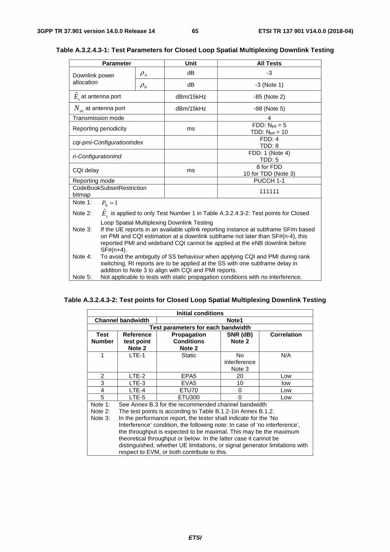
ETSI
ETSI TR 137 901 V14.0.0 (2018-04)653GPP TR 37.901 version 14.0.0 Release 14
Table A.3.2.4.3-1: Test Parameters for Closed Loop Spatial Multiplexing Downlink Testing
Parameter Unit All Tests
Downlink power allocation
dB -3
dB -3 (Note 1)
sE at antenna port
dBm/15kHz -85 (Note 2)
at antenna port dBm/15kHz -98 (Note 5)
Transmission mode
4
Reporting periodicity ms FDD: Npd = 5 TDD: Npd = 10
cqi-pmi-ConfigurationIndex FDD: 4 TDD: 8
ri-ConfigurationInd FDD: 1 (Note 4) TDD: 5
CQI delay
ms 8 for FDD 10 for TDD (Note 3)
Reporting mode
PUCCH 1-1 CodeBookSubsetRestriction bitmap 111111
Note 1: Note 2: sE is applied to only Test Number 1 in Table A.3.2.4.3-2: Test points for Closed
Loop Spatial Multiplexing Downlink Testing Note 3: If the UE reports in an available uplink reporting instance at subframe SF#n based
on PMI and CQI estimation at a downlink subframe not later than SF#(n-4), this reported PMI and wideband CQI cannot be applied at the eNB downlink before SF#(n+4).
Note 4: To avoid the ambiguity of SS behaviour when applying CQI and PMI during rank switching, RI reports are to be applied at the SS with one subframe delay in addition to Note 3 to align with CQI and PMI reports.
Note 5: Not applicable to tests with static propagation conditions with no interference.
Table A.3.2.4.3-2: Test points for Closed Loop Spatial Multiplexing Downlink Testing
Initial conditions Channel bandwidth Note1
Test parameters for each bandwidth Test
Number Reference test point
Note 2
Propagation Conditions
Note 2
SNR (dB) Note 2
Correlation
1 LTE-1 Static No interference
Note 3
N/A
2 LTE-2 EPA5 20 Low 3 LTE-3 EVA5 10 low 4 LTE-4 ETU70 0 Low 5 LTE-5 ETU300 0 Low
Note 1: See Annex B.3 for the recommended channel bandwidth Note 2: The test points is according to Table B.1.2-1in Annex B.1.2. Note 3: In the performance report, the tester shall indicate for the ‘No
Interference’ condition, the following note: In case of 'no interference', the throughput is expected to be maximal. This may be the maximum theoretical throughput or below. In the latter case it cannot be distinguished, whether UE limitations, or signal generator limitations with respect to EVM, or both contribute to this.
Aρ
Bρ
ocN
1=BP
ETSI
ETSI TR 137 901 V14.0.0 (2018-04)663GPP TR 37.901 version 14.0.0 Release 14
A.3.2.4.4 Test Description
A.3.2.4.4.1 Initial Conditions
Initial conditions are a set of test configurations the UE needs to be tested in and the steps for the SS to take with the UE to reach the correct measurement state.
Configurations of PDSCH and PDCCH before measurement are specified in Annex C.2 of TS 36.521-1 [2].
Test Environment: Normal, as defined in TS 36.508 [11] clause 4.1.
Frequencies to be tested: Mid Range, as defined in TS 36.508 [11] clause 4.3.1.1 for FDD and 4.3.1.2 for TDD.
1) Connect the SS, the faders and AWGN noise sources to the UE antenna connectors as shown in TS 36.508 [11] Annex A, Figure A.10 for antenna configuration 2x2.
2) Connect an application server to the IP output of the SS configured with a FTP server.
3) For a tethered configuration, tether the UE to a laptop configured with FTP client software using the appropriate UE to PC interface Modem or Network Interface Connection (NIC) drivers. For an embedded configuration, ensure that the UE has an FTP client test application available.
4) The parameter settings for the cell are set up according to Tables A.3.1-2, A.3.1-3 and A.3.2.4.3-1 as appropriate.
5) Downlink signals are initially set up according to Annex C0, C.1 and Annex C.3.2 in TS 36.521-1 [2] and uplink signals according to Annex H.1 and H.3.2 in TS 36.521-1 [2].
6) Propagation conditions are set according to Annex B.0 in TS 36.521-1 [2].
A.3.2.4.4.2 Procedure
1) SS transmits PDSCH via PDCCH DCI format 2 for C_RNTI to transmit the DL data using the transport format and transport block size determined based on UE reported CQI as described in subclause B.2.2.1.
2) Set the parameters of the bandwidth, MCS, reference channel, the propagation condition, the correlation matrix, antenna configuration and the SNR according to Table A.3.2.4.3-2, as appropriate.
3) Using the FTP client, begin FTP download from the application server of a file sufficient in size for the test duration outlined in Table A.3.1-1 and record Throughput T result. (This is iteration 1)
4) Repeat transfer for iterations 2-5 within the same call as the first iteration.
5) Calculate and record the average throughput of the five iterations.
6) Count and record the overall number of ACK and NACK/DTX on the PUSCH/PUCCH during the test interval.
7) If the RRC connection setup needs to be re-established after the subtest, perform the initial call setup in accordance with the initial conditions in clause A.3.2.4.4.1.
8) Repeat steps 1 to 6 for each subtest in Table A.3.2.3.4-2, as appropriate.
9) Record the IP address type (IPv4 or IPv6) used during the file transfers.
A.3.2.5 LTE / FTP Downlink / PDSCH Single-layer Spatial Multiplexing Performance (Port 5, UE-Specific Reference Symbols)
A.3.2.5.1 Definition
The UE application layer downlink performance for FTP under different multi-path fading environments is determined by the UE application layer FTP throughput T.

ETSI
ETSI TR 137 901 V14.0.0 (2018-04)673GPP TR 37.901 version 14.0.0 Release 14
A.3.2.5.2 Test Purpose
To measure the performance of the UE while downloading TCP based data within both static and multi path faded environments.
A.3.2.5.3 Test Parameters
Test parameters are defined in Table A.3.2.5.3-1 and A.3.2.5.3-2.
Table A.3.2.5.3-1: Test Parameters for Single-layer Spatial Multiplexing Downlink Testing
Parameter Unit All Tests
Downlink power allocation
dB 0 (1 Tx)
dB 0 (1 Tx) (Note 1)
σ dB 0
sE at antenna port
dBm/15kHz -85 (Note 2)
at antenna port dBm/15kHz -98 (Note 4)
Transmission mode
7
Beamforming model Annex B.4.1 in TS 36.521-1 [2]
Precoder update granularity Frequency domain: 1 PRB Time domain: 1 ms
Reporting periodicity ms FDD: Npd = 5 TDD: Npd = 10
cqi-pmi-ConfigurationIndex FDD: 4 TDD: 8
Reporting mode
PUCCH 1-0
Note 1: 0=BP
Note 2: sE is applied to only Test Number 1 in Table A.3.2.5.3-2: Test points for Single-
layer Spatial Multiplexing Downlink Testing Note 3: If the UE reports in an available uplink reporting instance at subframe SF#n based
on CQI estimation at a downlink subframe not later than SF#(n-4), this reported wideband CQI cannot be applied at the eNB downlink before SF#(n+4).
Note 4: Not applicable to tests with static propagation conditions with no interference.
Table A.3.2.5.3-2: Test points for Single-layer Spatial Multiplexing Downlink Testing
Initial conditions Channel bandwidth Note1
Test parameters for each bandwidth Test
Number Reference test point
Note 2
Propagation Conditions
Note 2
SNR (dB) Note 2
Correlation
1 LTE-1 Static No interference
Note 3
N/A
2 LTE-2 EPA5 20 Mid 3 LTE-3 EVA5 10 Mid 4 LTE-4 ETU70 0 Low 5 LTE-5 ETU300 0 Low
Note 1: See Annex B.3 for the recommended channel bandwidth Note 2: The test points is according to Table B.1.2-1in Annex B.1.2. Note 3: In the performance report, the tester shall indicate for the ‘No
Interference’ condition, the following note: In case of 'no interference', the throughput is expected to be maximal. This may be the maximum theoretical throughput or below. In the latter case it cannot be distinguished, whether UE limitations, or signal generator limitations with respect to EVM, or both contribute to this.
Aρ
Bρ
ocN
ETSI
ETSI TR 137 901 V14.0.0 (2018-04)683GPP TR 37.901 version 14.0.0 Release 14
A.3.2.5.4 Test Description
A.3.2.5.4.1 Initial Conditions
Initial conditions are a set of test configurations the UE needs to be tested in and the steps for the SS to take with the UE to reach the correct measurement state.
Configurations of PDSCH and PDCCH before measurement are specified in Annex C.2 of TS 36.521-1 [2].
Test Environment: Normal, as defined in TS 36.508 [11] clause 4.1.
Frequencies to be tested: Mid Range, as defined in TS 36.508 [11] clause 4.3.1.2.
1) Connect the SS, the faders and AWGN noise sources to the UE antenna connectors as shown in TS 36.508 [11] Annex A, Figure A.10 for antenna configuration 2x2.
2) Connect an application server to the IP output of the SS configured with a FTP server.
3) For a tethered configuration, tether the UE to a laptop configured with FTP client software using the appropriate UE to PC interface Modem or Network Interface Connection (NIC) drivers. For an embedded configuration, ensure that the UE has an FTP client test application available.
4) The parameter settings for the cell are set up according to Tables A.3.1-3 and A.3.2.5.3-1 as appropriate.
5) Downlink signals are initially set up according to Annex C0, C.1 and Annex C.3.2 in TS 36.521-1 [2] and uplink signals according to Annex H.1 and H.3.2 in TS 36.521-1 [2].
6) Propagation conditions are set according to Annex B.0 in TS 36.521-1 [2].
A.3.2.5.4.2 Procedure
1) SS transmits PDSCH via PDCCH DCI format 1 for C_RNTI to transmit the DL data using the transport format and transport block size determined based on UE reported CQI as described in sub-clause B.2.2.1.
2) Set the parameters of the bandwidth, MCS, reference channel, the propagation condition, the correlation matrix, antenna configuration and the SNR according to Table A.3.2.5.3-2, as appropriate.
3) Using the FTP client, begin FTP download from the application server of a file sufficient in size for the test duration outlined in Table A.3.1-1 and record Throughput T result. (This is iteration 1)
4) Repeat transfer for iterations 2-5 within the same call as the first iteration.
5) Calculate and record the average throughput of the five iterations.
6) Count and record the overall number of ACK and NACK/DTX on the PUSCH/PUCCH during the test interval.
7) If the RRC connection setup needs to be re-established after the subtest, perform the initial call setup in accordance with the initial conditions in clause A.3.2.5.4.1.
8) Repeat steps 1 to 6 for each subtest in Table A.3.2.5.3-2, as appropriate.
9) Record the IP address type (IPv4 or IPv6) used during the file transfers.
A.3.2.6 LTE / FTP Downlink / PDSCH Single-layer Spatial Multiplexing Performance (Port 7 or 8, UE-Specific Reference Symbols)
A.3.2.6.1 Definition
The UE application layer downlink performance for FTP under different multi-path fading environments is determined by the UE application layer FTP throughput T.
ETSI
ETSI TR 137 901 V14.0.0 (2018-04)693GPP TR 37.901 version 14.0.0 Release 14
A.3.2.6.2 Test Purpose
To measure the performance of the UE while downloading TCP based data within both static and multi path faded environments.
A.3.2.6.3 Test Parameters
Test parameters are defined in Table A.3.2.6.3-1 and A.3.2.6.3-2.
Table A.3.2.6.3-1: Test Parameters for Single-layer Spatial Multiplexing Downlink Testing
Parameter Unit All Tests
Downlink power allocation
dB 0
dB 0 (Note 1)
σ dB -3
sE at antenna port
dBm/15kHz -85 (Note 2)
at antenna port dBm/15kHz -98 (Note 4)
Transmission mode
8
Beamforming model Annex B.4.1 in TS 36.521-1 [2]
Precoder update granularity Frequency domain: 1 PRB Time domain: 1 ms
Reporting periodicity ms FDD: Npd = 5 TDD: Npd = 10
cqi-pmi-ConfigurationIndex FDD: 4 TDD: 8
Reporting mode
PUCCH 1-0
Note 1: Note 2: sE is applied to only Test Number 1 in Table A.3.2.6.3-2: Test points for Single-
layer Spatial Multiplexing Downlink Testing Note 3: If the UE reports in an available uplink reporting instance at subframe SF#n based
on PMI and CQI estimation at a downlink subframe not later than SF#(n-4), this reported PMI and wideband CQI cannot be applied at the eNB downlink before SF#(n+4).
Note 4: Not applicable to tests with static propagation conditions with no interference.
Aρ
Bρ
ocN
1=BP
ETSI
ETSI TR 137 901 V14.0.0 (2018-04)703GPP TR 37.901 version 14.0.0 Release 14
Table A.3.2.6.3-2: Test points for Single-layer Spatial Multiplexing Downlink Testing
Initial conditions Channel bandwidth Note1
Test parameters for each bandwidth Test
Number Reference test point
Note 2
Propagation Conditions
Note 2
SNR (dB) Note 2
Correlation
1 LTE-1 Static No interference
Note 3
N/A
2 LTE-2 EPA5 20 Mid 3 LTE-3 EVA5 10 Mid 4 LTE-4 ETU70 0 Low 5 LTE-5 ETU300 0 Low
Note 1: See Annex B.3 for the recommended channel bandwidth Note 2: The test points is according to Table B.1.2-1in Annex B.1.2. Note 3: In the performance report, the tester shall indicate for the ‘No
Interference’ condition, the following note: In case of 'no interference', the throughput is expected to be maximal. This may be the maximum theoretical throughput or below. In the latter case it cannot be distinguished, whether UE limitations, or signal generator limitations with respect to EVM, or both contribute to this.
A.3.2.6.4 Test Description
A.3.2.6.4.1 Initial Conditions
Initial conditions are a set of test configurations the UE needs to be tested in and the steps for the SS to take with the UE to reach the correct measurement state.
Configurations of PDSCH and PDCCH before measurement are specified in Annex C.2 of TS 36.521-1 [2].
Test Environment: Normal, as defined in TS 36.508 [11] clause 4.1.
Frequencies to be tested: Mid Range, as defined in TS 36.508 [11] clause 4.3.1.2.
1) Connect the SS, the faders and AWGN noise sources to the UE antenna connectors as shown in TS 36.508 [11] Annex A, Figure A.10 for antenna configuration 2x2.
2) Connect an application server to the IP output of the SS configured with a FTP server.
3) For a tethered configuration, tether the UE to a laptop configured with FTP client software using the appropriate UE to PC interface Modem or Network Interface Connection (NIC) drivers. For an embedded configuration, ensure that the UE has an FTP client test application available.
4) The parameter settings for the cell are set up according to Tables A.3.1-3 and A.3.2.6.3-1 as appropriate.
5) Downlink signals are initially set up according to Annex C0, C.1 and Annex C.3.2 in TS 36.521-1 [2] and uplink signals according to Annex H.1 and H.3.2 in TS 36.521-1 [2].
6) Propagation conditions are set according to Annex B.0 in TS 36.521-1 [2].
A.3.2.6.4.2 Procedure
1) SS transmits PDSCH via PDCCH DCI format 2B for C_RNTI to transmit the DL data using the transport format and transport block size determined based on UE reported CQI as described in sub-clause B.2.2.1.
2) Set the parameters of the bandwidth, MCS, reference channel, the propagation condition, the correlation matrix, antenna configuration and the SNR according to Table A.3.2.5.3-2, as appropriate.
3) Using the FTP client, begin FTP download from the application server of a file sufficient in size for the test duration outlined in Table A.3.1-1 and record Throughput T result. (This is iteration 1)
ETSI
ETSI TR 137 901 V14.0.0 (2018-04)713GPP TR 37.901 version 14.0.0 Release 14
4) Repeat transfer for iterations 2-5 within the same call as the first iteration.
5) Calculate and record the average throughput of the five iterations.
6) Count and record the overall number of ACK and NACK/DTX on the PUSCH/PUCCH during the test interval.
7) If the RRC connection setup needs to be re-established after the subtest, perform the initial call setup in accordance with the initial conditions in clause A.3.2.6.4.1.
8) Repeat steps 1 to 6 for each subtest in Table A.3.2.6.3-2, as appropriate.
9) Record the IP address type (IPv4 or IPv6) used during the file transfers.
A.3.2.7 LTE / FTP Downlink / PDSCH Dual-layer Spatial Multiplexing Performance (port 7 and 8, User-Specific Reference Symbols)
A.3.2.7.1 Definition
The UE application layer downlink performance for FTP under different multi-path fading environments is determined by the UE application layer FTP throughput T.
A.3.2.7.2 Test Purpose
To measure the performance of the UE while downloading TCP based data within both static and multi path faded environments.
A.3.2.7.3 Test Parameters
Test parameters are defined in Table A.3.2.7.3-1 and A.3.2.7.3-2.
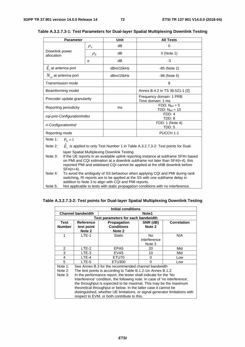
ETSI
ETSI TR 137 901 V14.0.0 (2018-04)723GPP TR 37.901 version 14.0.0 Release 14
Table A.3.2.7.3-1: Test Parameters for Dual-layer Spatial Multiplexing Downlink Testing
Parameter Unit All Tests
Downlink power allocation
dB 0
dB 0 (Note 1)
σ dB -3
sE at antenna port
dBm/15kHz -85 (Note 2)
at antenna port dBm/15kHz -98 (Note 5)
Transmission mode
8
Beamforming model Annex B.4.2 in TS 36.521-1 [2]
Precoder update granularity Frequency domain: 1 PRB Time domain: 1 ms
Reporting periodicity ms FDD: Npd = 5 TDD: Npd = 10
cqi-pmi-ConfigurationIndex FDD: 4 TDD: 8
ri-ConfigurationInd FDD: 1 (Note 4) TDD: 5
Reporting mode
PUCCH 1-1
Note 1: 1=BP
Note 2: sE is applied to only Test Number 1 in Table A.3.2.7.3-2: Test points for Dual-
layer Spatial Multiplexing Downlink Testing Note 3: If the UE reports in an available uplink reporting instance at subframe SF#n based
on PMI and CQI estimation at a downlink subframe not later than SF#(n-4), this reported PMI and wideband CQI cannot be applied at the eNB downlink before SF#(n+4).
Note 4: To avoid the ambiguity of SS behaviour when applying CQI and PMI during rank switching, RI reports are to be applied at the SS with one subframe delay in addition to Note 3 to align with CQI and PMI reports.
Note 5: Not applicable to tests with static propagation conditions with no interference.
Table A.3.2.7.3-2: Test points for Dual-layer Spatial Multiplexing Downlink Testing
Initial conditions Channel bandwidth Note1
Test parameters for each bandwidth Test
Number Reference test point
Note 2
Propagation Conditions
Note 2
SNR (dB) Note 2
Correlation
1 LTE-1 Static No interference
Note 3
N/A
2 LTE-2 EPA5 20 Mid 3 LTE-3 EVA5 10 Mid 4 LTE-4 ETU70 0 Low 5 LTE-5 ETU300 0 Low
Note 1: See Annex B.3 for the recommended channel bandwidth Note 2: The test points is according to Table B.1.2-1in Annex B.1.2. Note 3: In the performance report, the tester shall indicate for the ‘No
Interference’ condition, the following note: In case of 'no interference', the throughput is expected to be maximal. This may be the maximum theoretical throughput or below. In the latter case it cannot be distinguished, whether UE limitations, or signal generator limitations with respect to EVM, or both contribute to this.
Aρ
Bρ
ocN
ETSI
ETSI TR 137 901 V14.0.0 (2018-04)733GPP TR 37.901 version 14.0.0 Release 14
A.3.2.7.4 Test Description
A.3.2.7.4.1 Initial Conditions
Initial conditions are a set of test configurations the UE needs to be tested in and the steps for the SS to take with the UE to reach the correct measurement state.
Configurations of PDSCH and PDCCH before measurement are specified in Annex C.2 of TS 36.521-1 [2].
Test Environment: Normal, as defined in TS 36.508 [11] clause 4.1.
Frequencies to be tested: Mid Range, as defined in TS 36.508 [11] clause 4.3.1.2.
1) Connect the SS, the faders and AWGN noise sources to the UE antenna connectors as shown in TS 36.508 [11] Annex A, Figure A.10 for antenna configuration 2x2.
2) Connect an application server to the IP output of the SS configured with a FTP server.
3) For a tethered configuration, tether the UE to a laptop configured with FTP client software using the appropriate UE to PC interface Modem or Network Interface Connection (NIC) drivers. For an embedded configuration, ensure that the UE has an FTP client test application available.
4) The parameter settings for the cell are set up according to Tables A.3.1-3 and A.3.2.7.3-1 as appropriate.
5) Downlink signals are initially set up according to Annex C0, C.1 and Annex C.3.2 in TS 36.521-1 [2] and uplink signals according to Annex H.1 and H.3.2 in TS 36.521-1 [2].
6) Propagation conditions are set according to Annex B.0 in TS 36.521-1 [2].
A.3.2.7.4.2 Procedure
1) SS transmits PDSCH via PDCCH DCI format 2B for C_RNTI to transmit the DL data using the transport format and transport block size determined based on UE reported CQI as described in sub-clause B.2.2.1.
2) Set the parameters of the bandwidth, MCS, reference channel, the propagation condition, the correlation matrix, antenna configuration and the SNR according to Table A.3.2.7.3-2, as appropriate.
3) Using the FTP client, begin FTP download from the application server of a file sufficient in size for the test duration outlined in Table A.3.1-1 and record Throughput T result. (This is iteration 1)
4) Repeat transfer for iterations 2-5 within the same call as the first iteration.
5) Calculate and record the average throughput of the five iterations.
6) Count and record the overall number of ACK and NACK/DTX on the PUSCH/PUCCH during the test interval.
7) If the RRC connection setup needs to be re-established after the subtest, perform the initial call setup in accordance with the initial conditions in clause A.3.2.7.4.1.
8) Repeat steps 1 to 6 for each subtest in Table A.3.2.7.3-2, as appropriate.
9) Record the IP address type (IPv4 or IPv6) used during the file transfers.
A.3.3 LTE / UDP Downlink Performance
A.3.3.1 LTE / UDP Downlink / PDSCH Single Antenna Port Performance (Cell-Specific Reference Symbols)
A.3.3.1.1 Definition
The UE application layer downlink performance for UDP under different multi-path fading environments is determined by the UE application layer UDP throughput T.
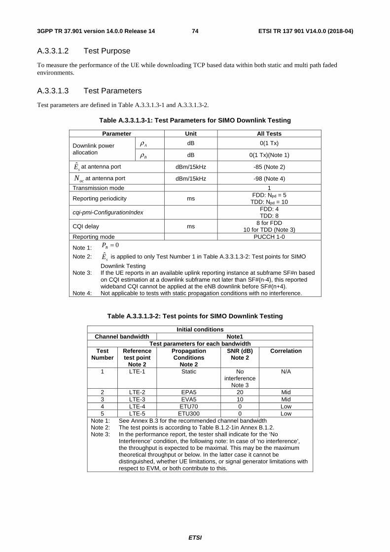
ETSI
ETSI TR 137 901 V14.0.0 (2018-04)743GPP TR 37.901 version 14.0.0 Release 14
A.3.3.1.2 Test Purpose
To measure the performance of the UE while downloading TCP based data within both static and multi path faded environments.
A.3.3.1.3 Test Parameters
Test parameters are defined in Table A.3.3.1.3-1 and A.3.3.1.3-2.
Table A.3.3.1.3-1: Test Parameters for SIMO Downlink Testing
Parameter Unit All Tests
Downlink power allocation
dB 0(1 Tx)
dB 0(1 Tx)(Note 1)
sE at antenna port
dBm/15kHz -85 (Note 2)
at antenna port dBm/15kHz -98 (Note 4)
Transmission mode
1
Reporting periodicity ms FDD: Npd = 5 TDD: Npd = 10
cqi-pmi-ConfigurationIndex FDD: 4 TDD: 8
CQI delay
ms 8 for FDD 10 for TDD (Note 3)
Reporting mode
PUCCH 1-0
Note 1:
Note 2: sE is applied to only Test Number 1 in Table A.3.3.1.3-2: Test points for SIMO
Downlink Testing Note 3: If the UE reports in an available uplink reporting instance at subframe SF#n based
on CQI estimation at a downlink subframe not later than SF#(n-4), this reported wideband CQI cannot be applied at the eNB downlink before SF#(n+4).
Note 4: Not applicable to tests with static propagation conditions with no interference.
Table A.3.3.1.3-2: Test points for SIMO Downlink Testing
Initial conditions Channel bandwidth Note1
Test parameters for each bandwidth Test
Number Reference test point
Note 2
Propagation Conditions
Note 2
SNR (dB) Note 2
Correlation
1 LTE-1 Static No interference
Note 3
N/A
2 LTE-2 EPA5 20 Mid 3 LTE-3 EVA5 10 Mid 4 LTE-4 ETU70 0 Low 5 LTE-5 ETU300 0 Low
Note 1: See Annex B.3 for the recommended channel bandwidth Note 2: The test points is according to Table B.1.2-1in Annex B.1.2. Note 3: In the performance report, the tester shall indicate for the ‘No
Interference’ condition, the following note: In case of 'no interference', the throughput is expected to be maximal. This may be the maximum theoretical throughput or below. In the latter case it cannot be distinguished, whether UE limitations, or signal generator limitations with respect to EVM, or both contribute to this.
Aρ
Bρ
ocN
0=BP
ETSI
ETSI TR 137 901 V14.0.0 (2018-04)753GPP TR 37.901 version 14.0.0 Release 14
A.3.3.1.4 Test Description
A.3.3.1.4.1 Initial Conditions
Initial conditions are a set of test configurations the UE needs to be tested in and the steps for the SS to take with the UE to reach the correct measurement state.
Configurations of PDSCH and PDCCH before measurement are specified in Annex C.2 of TS 36.521-1 [2].
Test Environment: Normal, as defined in TS 36.508 [11] clause 4.1.
Frequencies to be tested: Mid Range, as defined in TS 36.508 [11] clause 4.3.1.1 for FDD and 4.3.1.2 for TDD.
1) Connect the SS, the faders and AWGN noise sources to the UE antenna connectors as shown in TS 36.508 [11] Annex A, Figure A.9 for antenna configuration 2x2.
2) Connect an application server to the IP output of the SS configured with a UDP server.
3) For a tethered configuration, tether the UE to a laptop configured with UDP client software using the appropriate UE to PC interface Modem or Network Interface Connection (NIC) drivers. For an embedded configuration, ensure that the UE has an UDP client test application available.
4) The parameter settings for the cell are set up according to Tables A.3.1-2, A.3.1-3 and A.3.3.1.3-1 as appropriate.
5) Downlink signals are initially set up according to Annex C0, C.1 and Annex C.3.2 in TS 36.521-1 [2] and uplink signals according to Annex H.1 and H.3.2 in TS 36.521-1 [2].
6) Propagation conditions are set according to Annex B.0 in TS 36.521-1 [2].
A.3.3.1.4.2 Procedure
1) SS transmits PDSCH via PDCCH DCI format 1A for C_RNTI to transmit the DL data using the transport format and transport block size determined based on UE reported CQI as described in subclause B.2.2.1.
2) Set the parameters of the bandwidth, MCS, reference channel, the propagation condition, the correlation matrix, antenna configuration and the SNR according to Table A.3.3.1.3-2, as appropriate.
3) Using the UDP client, begin UDP download from the application server of a file sufficient in size for the test duration outlined in Table A.3.1-1 and record Throughput T result. (This is iteration 1)
4) Repeat transfer for iterations 2-5 within the same call as the first iteration.
5) Calculate and record the average throughput of the five iterations.
6) Count and record the overall number of ACK and NACK/DTX on the PUSCH/PUCCH during the test interval.
7) If the RRC connection setup needs to be re-established after the subtest, perform the initial call setup in accordance with the initial conditions in clause A.3.3.1.4.1.
8) Repeat steps 1 to 6 for each subtest in Table A.3.3.1.3-2, as appropriate.
9) Record the IP address type (IPv4 or IPv6) used during the file transfers.
A.3.3.2 LTE / UDP Downlink / PDSCH Transmit Diversity Performance (Cell-Specific Reference Symbols)
A.3.3.2.1 Definition
The UE application layer downlink performance for UDP under different multi-path fading environments is determined by the UE application layer UDP throughput T.
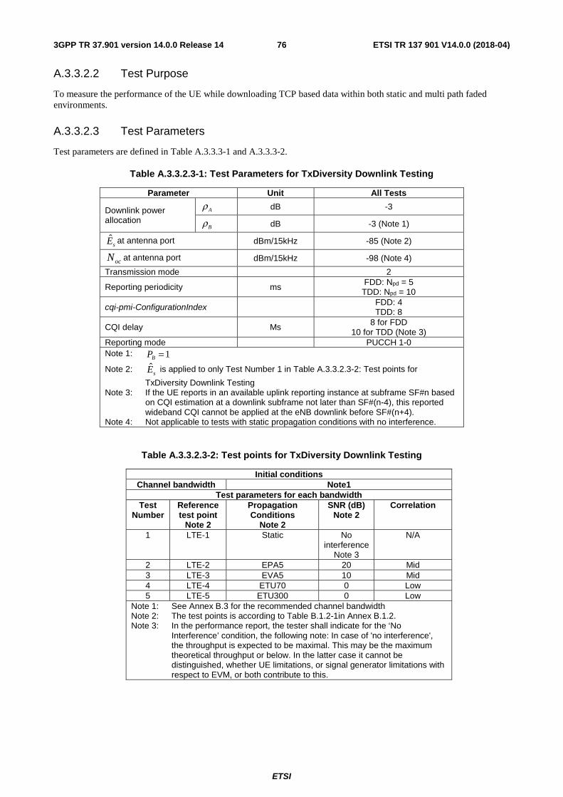
ETSI
ETSI TR 137 901 V14.0.0 (2018-04)763GPP TR 37.901 version 14.0.0 Release 14
A.3.3.2.2 Test Purpose
To measure the performance of the UE while downloading TCP based data within both static and multi path faded environments.
A.3.3.2.3 Test Parameters
Test parameters are defined in Table A.3.3.3-1 and A.3.3.3-2.
Table A.3.3.2.3-1: Test Parameters for TxDiversity Downlink Testing
Parameter Unit All Tests
Downlink power allocation
dB -3
dB -3 (Note 1)
sE at antenna port
dBm/15kHz -85 (Note 2)
at antenna port dBm/15kHz -98 (Note 4)
Transmission mode
2
Reporting periodicity ms FDD: Npd = 5 TDD: Npd = 10
cqi-pmi-ConfigurationIndex FDD: 4 TDD: 8
CQI delay
Ms 8 for FDD 10 for TDD (Note 3)
Reporting mode
PUCCH 1-0 Note 1: Note 2: sE is applied to only Test Number 1 in Table A.3.3.2.3-2: Test points for
TxDiversity Downlink Testing Note 3: If the UE reports in an available uplink reporting instance at subframe SF#n based
on CQI estimation at a downlink subframe not later than SF#(n-4), this reported wideband CQI cannot be applied at the eNB downlink before SF#(n+4).
Note 4: Not applicable to tests with static propagation conditions with no interference.
Table A.3.3.2.3-2: Test points for TxDiversity Downlink Testing
Initial conditions Channel bandwidth Note1
Test parameters for each bandwidth Test
Number Reference test point
Note 2
Propagation Conditions
Note 2
SNR (dB) Note 2
Correlation
1 LTE-1 Static No interference
Note 3
N/A
2 LTE-2 EPA5 20 Mid 3 LTE-3 EVA5 10 Mid 4 LTE-4 ETU70 0 Low 5 LTE-5 ETU300 0 Low
Note 1: See Annex B.3 for the recommended channel bandwidth Note 2: The test points is according to Table B.1.2-1in Annex B.1.2. Note 3: In the performance report, the tester shall indicate for the ‘No
Interference’ condition, the following note: In case of 'no interference', the throughput is expected to be maximal. This may be the maximum theoretical throughput or below. In the latter case it cannot be distinguished, whether UE limitations, or signal generator limitations with respect to EVM, or both contribute to this.
Aρ
Bρ
ocN
1=BP
ETSI
ETSI TR 137 901 V14.0.0 (2018-04)773GPP TR 37.901 version 14.0.0 Release 14
A.3.3.2.4 Test Description
A.3.3.2.4.1 Initial Conditions
Initial conditions are a set of test configurations the UE needs to be tested in and the steps for the SS to take with the UE to reach the correct measurement state.
Configurations of PDSCH and PDCCH before measurement are specified in Annex C.2 of TS 36.521-1 [2].
Test Environment: Normal, as defined in TS 36.508 [11] clause 4.1.
Frequencies to be tested: Mid Range, as defined in TS 36.508 [11] clause 4.3.1.1 for FDD and 4.3.1.2 for TDD.
1) Connect the SS, the faders and AWGN noise sources to the UE antenna connectors as shown in TS 36.508 [11] Annex A, Figure A.10 for antenna configuration 2x2.
2) Connect an application server to the IP output of the SS configured with a UDP server.
3) For a tethered configuration, tether the UE to a laptop configured with UDP client software using the appropriate UE to PC interface Modem or Network Interface Connection (NIC) drivers. For an embedded configuration, ensure that the UE has an UDP client test application available.
4) The parameter settings for the cell are set up according to Tables A.3.1-2, A.3.1-3 and A.3.3.2.3-1 as appropriate.
5) Downlink signals are initially set up according to Annex C0, C.1 and Annex C.3.2 in TS 36.521-1 [2] and uplink signals according to Annex H.1 and H.3.2 in TS 36.521-1 [2].
6) Propagation conditions are set according to Annex B.0 in TS 36.521-1 [2].
A.3.3.2.4.2 Procedure
1) SS transmits PDSCH via PDCCH DCI format 1A for C_RNTI to transmit the DL data using the transport format and transport block size determined based on UE reported CQI as described in subclause B.2.2.1.
2) Set the parameters of the bandwidth, MCS, reference channel, the propagation condition, the correlation matrix, antenna configuration and the SNR according to Table A.3.3.2.3-2, as appropriate.
3) Using the UDP client, begin UDP download from the application server of a file sufficient in size for the test duration outlined in Table A.3.1-1 and record Throughput T result. (This is iteration 1)
4) Repeat transfer for iterations 2-5 within the same call as the first iteration.
5) Calculate and record the average throughput of the five iterations.
6) Count and record the overall number of ACK and NACK/DTX on the PUSCH/PUCCH during the test interval.
7) If the RRC connection setup needs to be re-established after the subtest, perform the initial call setup in accordance with the initial conditions in clause A.3.3.2.4.1.
8) Repeat steps 1 to 6 for each subtest in Table A.3.3.2.3-2, as appropriate.
9) Record the IP address type (IPv4 or IPv6) used during the file transfers.
A.3.3.3 LTE / UDP Downlink / PDSCH Open Loop Spatial Multiplexing Performance (Cell-Specific Reference Symbols)
A.3.3.3.1 Definition
The UE application layer downlink performance for UDP under different multi-path fading environments is determined by the UE application layer UDP throughput T.
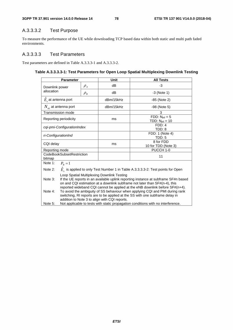
ETSI
ETSI TR 137 901 V14.0.0 (2018-04)783GPP TR 37.901 version 14.0.0 Release 14
A.3.3.3.2 Test Purpose
To measure the performance of the UE while downloading TCP based data within both static and multi path faded environments.
A.3.3.3.3 Test Parameters
Test parameters are defined in Table A.3.3.3-1 and A.3.3.3-2.
Table A.3.3.3.3-1: Test Parameters for Open Loop Spatial Multiplexing Downlink Testing
Parameter Unit All Tests
Downlink power allocation
dB -3
dB -3 (Note 1)
sE at antenna port
dBm/15kHz -85 (Note 2)
at antenna port dBm/15kHz -98 (Note 5)
Transmission mode
3
Reporting periodicity ms FDD: Npd = 5 TDD: Npd = 10
cqi-pmi-ConfigurationIndex FDD: 4 TDD: 8
ri-ConfigurationInd FDD: 1 (Note 4) TDD: 5
CQI delay
ms 8 for FDD 10 for TDD (Note 3)
Reporting mode
PUCCH 1-0 CodeBookSubsetRestriction bitmap 11
Note 1: Note 2: sE is applied to only Test Number 1 in Table A.3.3.3.3-2: Test points for Open
Loop Spatial Multiplexing Downlink Testing Note 3: If the UE reports in an available uplink reporting instance at subframe SF#n based
on and CQI estimation at a downlink subframe not later than SF#(n-4), this reported wideband CQI cannot be applied at the eNB downlink before SF#(n+4).
Note 4: To avoid the ambiguity of SS behaviour when applying CQI and PMI during rank switching, RI reports are to be applied at the SS with one subframe delay in addition to Note 3 to align with CQI reports.
Note 5: Not applicable to tests with static propagation conditions with no interference.
Aρ
Bρ
ocN
1=BP
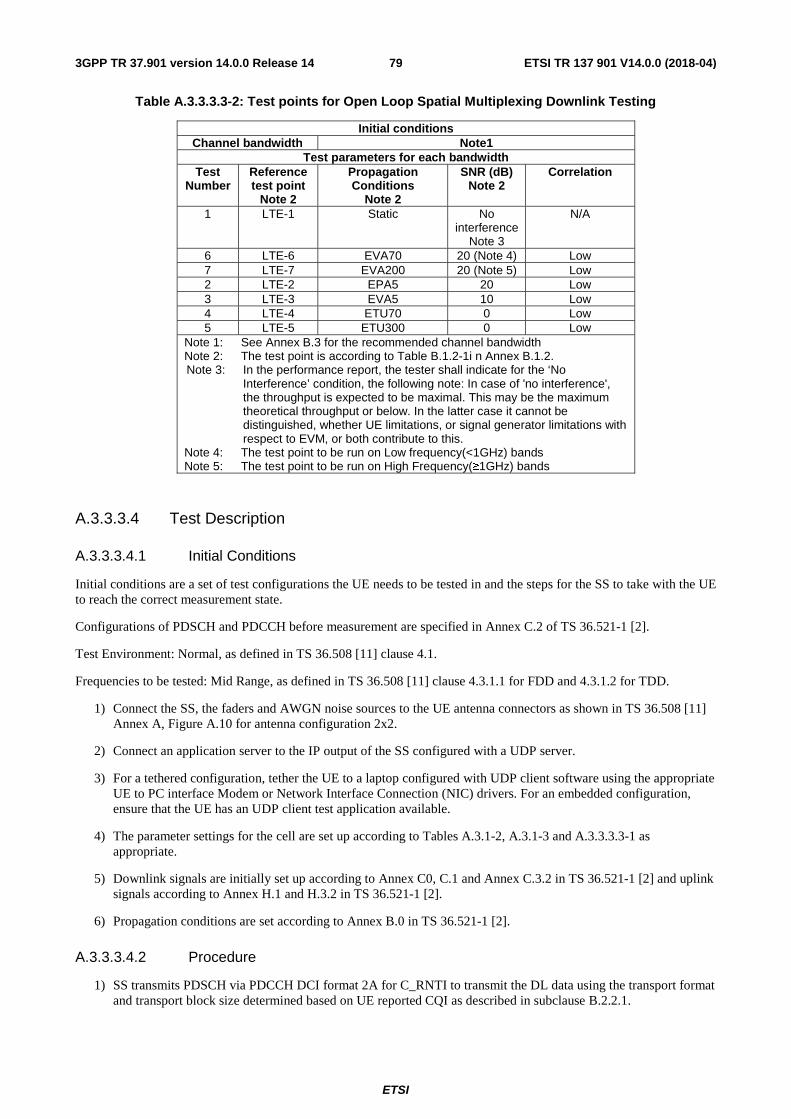
ETSI
ETSI TR 137 901 V14.0.0 (2018-04)793GPP TR 37.901 version 14.0.0 Release 14
Table A.3.3.3.3-2: Test points for Open Loop Spatial Multiplexing Downlink Testing
Initial conditions Channel bandwidth Note1
Test parameters for each bandwidth Test
Number Reference test point
Note 2
Propagation Conditions
Note 2
SNR (dB) Note 2
Correlation
1 LTE-1 Static No interference
Note 3
N/A
6 LTE-6 EVA70 20 (Note 4) Low 7 LTE-7 EVA200 20 (Note 5) Low 2 LTE-2 EPA5 20 Low 3 LTE-3 EVA5 10 Low 4 LTE-4 ETU70 0 Low 5 LTE-5 ETU300 0 Low
Note 1: See Annex B.3 for the recommended channel bandwidth Note 2: The test point is according to Table B.1.2-1i n Annex B.1.2. Note 3: In the performance report, the tester shall indicate for the ‘No
Interference’ condition, the following note: In case of 'no interference', the throughput is expected to be maximal. This may be the maximum theoretical throughput or below. In the latter case it cannot be distinguished, whether UE limitations, or signal generator limitations with respect to EVM, or both contribute to this.
Note 4: The test point to be run on Low frequency(<1GHz) bands Note 5: The test point to be run on High Frequency(≥1GHz) bands
A.3.3.3.4 Test Description
A.3.3.3.4.1 Initial Conditions
Initial conditions are a set of test configurations the UE needs to be tested in and the steps for the SS to take with the UE to reach the correct measurement state.
Configurations of PDSCH and PDCCH before measurement are specified in Annex C.2 of TS 36.521-1 [2].
Test Environment: Normal, as defined in TS 36.508 [11] clause 4.1.
Frequencies to be tested: Mid Range, as defined in TS 36.508 [11] clause 4.3.1.1 for FDD and 4.3.1.2 for TDD.
1) Connect the SS, the faders and AWGN noise sources to the UE antenna connectors as shown in TS 36.508 [11] Annex A, Figure A.10 for antenna configuration 2x2.
2) Connect an application server to the IP output of the SS configured with a UDP server.
3) For a tethered configuration, tether the UE to a laptop configured with UDP client software using the appropriate UE to PC interface Modem or Network Interface Connection (NIC) drivers. For an embedded configuration, ensure that the UE has an UDP client test application available.
4) The parameter settings for the cell are set up according to Tables A.3.1-2, A.3.1-3 and A.3.3.3.3-1 as appropriate.
5) Downlink signals are initially set up according to Annex C0, C.1 and Annex C.3.2 in TS 36.521-1 [2] and uplink signals according to Annex H.1 and H.3.2 in TS 36.521-1 [2].
6) Propagation conditions are set according to Annex B.0 in TS 36.521-1 [2].
A.3.3.3.4.2 Procedure
1) SS transmits PDSCH via PDCCH DCI format 2A for C_RNTI to transmit the DL data using the transport format and transport block size determined based on UE reported CQI as described in subclause B.2.2.1.
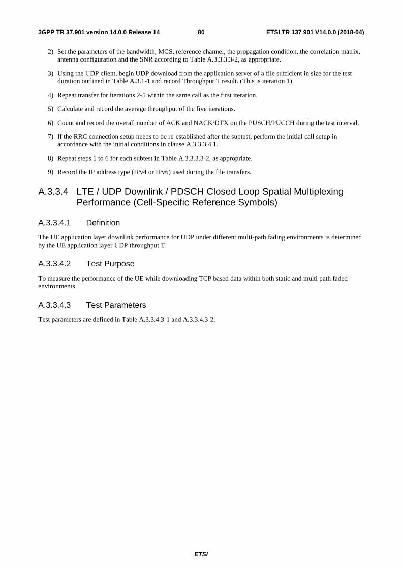
ETSI
ETSI TR 137 901 V14.0.0 (2018-04)803GPP TR 37.901 version 14.0.0 Release 14
2) Set the parameters of the bandwidth, MCS, reference channel, the propagation condition, the correlation matrix, antenna configuration and the SNR according to Table A.3.3.3.3-2, as appropriate.
3) Using the UDP client, begin UDP download from the application server of a file sufficient in size for the test duration outlined in Table A.3.1-1 and record Throughput T result. (This is iteration 1)
4) Repeat transfer for iterations 2-5 within the same call as the first iteration.
5) Calculate and record the average throughput of the five iterations.
6) Count and record the overall number of ACK and NACK/DTX on the PUSCH/PUCCH during the test interval.
7) If the RRC connection setup needs to be re-established after the subtest, perform the initial call setup in accordance with the initial conditions in clause A.3.3.3.4.1.
8) Repeat steps 1 to 6 for each subtest in Table A.3.3.3.3-2, as appropriate.
9) Record the IP address type (IPv4 or IPv6) used during the file transfers.
A.3.3.4 LTE / UDP Downlink / PDSCH Closed Loop Spatial Multiplexing Performance (Cell-Specific Reference Symbols)
A.3.3.4.1 Definition
The UE application layer downlink performance for UDP under different multi-path fading environments is determined by the UE application layer UDP throughput T.
A.3.3.4.2 Test Purpose
To measure the performance of the UE while downloading TCP based data within both static and multi path faded environments.
A.3.3.4.3 Test Parameters
Test parameters are defined in Table A.3.3.4.3-1 and A.3.3.4.3-2.
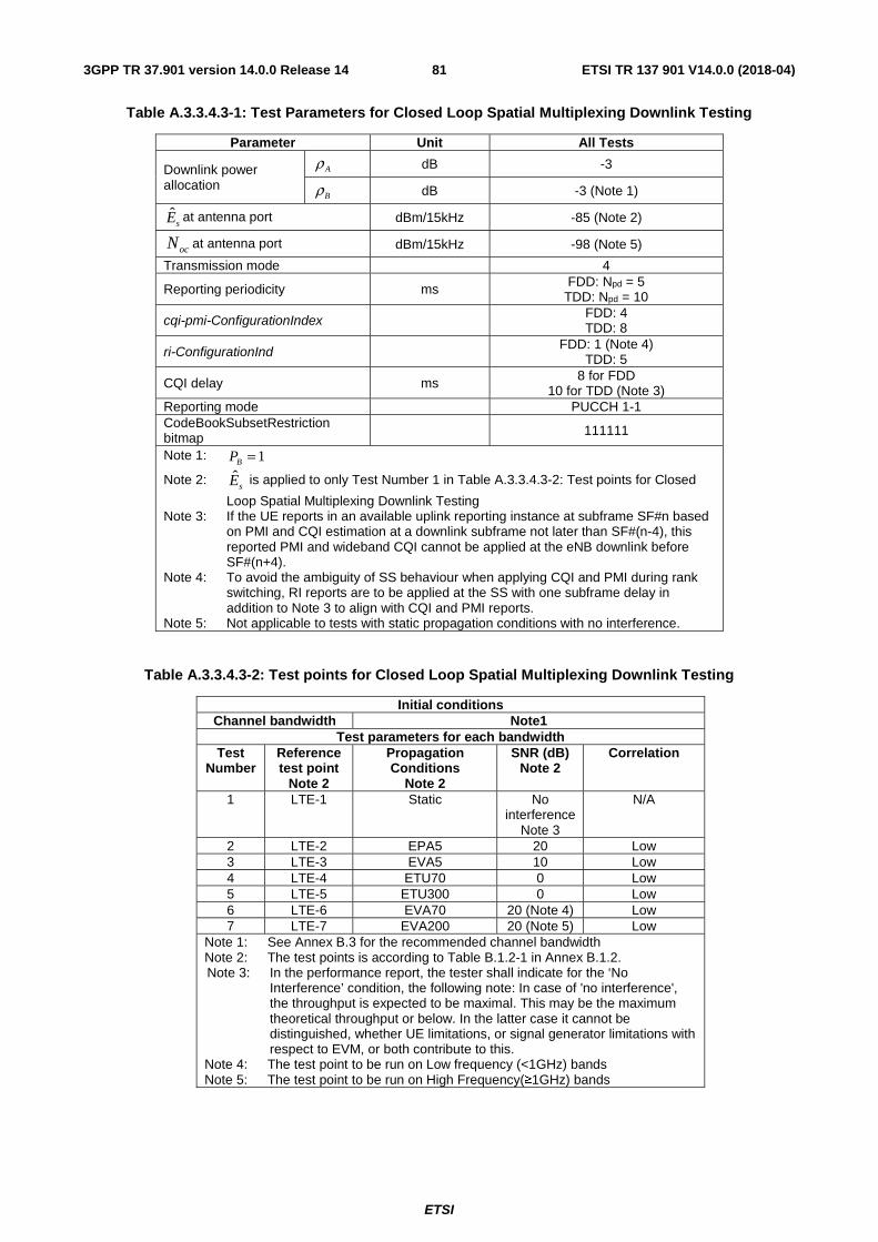
ETSI
ETSI TR 137 901 V14.0.0 (2018-04)813GPP TR 37.901 version 14.0.0 Release 14
Table A.3.3.4.3-1: Test Parameters for Closed Loop Spatial Multiplexing Downlink Testing
Parameter Unit All Tests
Downlink power allocation
dB -3
dB -3 (Note 1)
sE at antenna port
dBm/15kHz -85 (Note 2)
at antenna port dBm/15kHz -98 (Note 5)
Transmission mode
4
Reporting periodicity ms FDD: Npd = 5 TDD: Npd = 10
cqi-pmi-ConfigurationIndex FDD: 4 TDD: 8
ri-ConfigurationInd FDD: 1 (Note 4) TDD: 5
CQI delay
ms 8 for FDD 10 for TDD (Note 3)
Reporting mode
PUCCH 1-1 CodeBookSubsetRestriction bitmap 111111
Note 1: Note 2: sE is applied to only Test Number 1 in Table A.3.3.4.3-2: Test points for Closed
Loop Spatial Multiplexing Downlink Testing Note 3: If the UE reports in an available uplink reporting instance at subframe SF#n based
on PMI and CQI estimation at a downlink subframe not later than SF#(n-4), this reported PMI and wideband CQI cannot be applied at the eNB downlink before SF#(n+4).
Note 4: To avoid the ambiguity of SS behaviour when applying CQI and PMI during rank switching, RI reports are to be applied at the SS with one subframe delay in addition to Note 3 to align with CQI and PMI reports.
Note 5: Not applicable to tests with static propagation conditions with no interference.
Table A.3.3.4.3-2: Test points for Closed Loop Spatial Multiplexing Downlink Testing
Initial conditions Channel bandwidth Note1
Test parameters for each bandwidth Test
Number Reference test point
Note 2
Propagation Conditions
Note 2
SNR (dB) Note 2
Correlation
1 LTE-1 Static No interference
Note 3
N/A
2 LTE-2 EPA5 20 Low 3 LTE-3 EVA5 10 Low 4 LTE-4 ETU70 0 Low 5 LTE-5 ETU300 0 Low 6 LTE-6 EVA70 20 (Note 4) Low 7 LTE-7 EVA200 20 (Note 5) Low
Note 1: See Annex B.3 for the recommended channel bandwidth Note 2: The test points is according to Table B.1.2-1 in Annex B.1.2. Note 3: In the performance report, the tester shall indicate for the ‘No
Interference’ condition, the following note: In case of 'no interference', the throughput is expected to be maximal. This may be the maximum theoretical throughput or below. In the latter case it cannot be distinguished, whether UE limitations, or signal generator limitations with respect to EVM, or both contribute to this.
Note 4: The test point to be run on Low frequency (<1GHz) bands Note 5: The test point to be run on High Frequency(≥1GHz) bands
Aρ
Bρ
ocN
1=BP

ETSI
ETSI TR 137 901 V14.0.0 (2018-04)823GPP TR 37.901 version 14.0.0 Release 14
A.3.3.4.4 Test Description
A.3.3.4.4.1 Initial Conditions
Initial conditions are a set of test configurations the UE needs to be tested in and the steps for the SS to take with the UE to reach the correct measurement state.
Configurations of PDSCH and PDCCH before measurement are specified in Annex C.2 of TS 36.521-1 [2].
Test Environment: Normal, as defined in TS 36.508 [11] clause 4.1.
Frequencies to be tested: Mid Range, as defined in TS 36.508 [11] clause 4.3.1.1 for FDD and 4.3.1.2 for TDD.
1) Connect the SS, the faders and AWGN noise sources to the UE antenna connectors as shown in TS 36.508 [11] Annex A, Figure A.10 for antenna configuration 2x2.
2) Connect an application server to the IP output of the SS configured with a UDP server.
3) For a tethered configuration, tether the UE to a laptop configured with UDP client software using the appropriate UE to PC interface Modem or Network Interface Connection (NIC) drivers. For an embedded configuration, ensure that the UE has an UDP client test application available.
4) The parameter settings for the cell are set up according to Tables A.3.1-2, A.3.1-3 and A.3.3.4.3-1 as appropriate.
5) Downlink signals are initially set up according to Annex C0, C.1 and Annex C.3.2 in TS 36.521-1 [2] and uplink signals according to Annex H.1 and H.3.2 in TS 36.521-1 [2].
6) Propagation conditions are set according to Annex B.0 in TS 36.521-1 [2].
A.3.3.4.4.2 Procedure
1) SS transmits PDSCH via PDCCH DCI format 2 for C_RNTI to transmit the DL data using the transport format and transport block size determined based on UE reported CQI as described in subclause B.2.2.1.
2) Set the parameters of the bandwidth, MCS, reference channel, the propagation condition, the correlation matrix, antenna configuration and the SNR according to Table A.3.3.4.3-2, as appropriate.
3) Using the UDP client, begin UDP download from the application server of a file sufficient in size for the test duration outlined in Table A.3.1-1 and record Throughput T result. (This is iteration 1)
4) Repeat transfer for iterations 2-5 within the same call as the first iteration.
5) Calculate and record the average throughput of the five iterations.
6) Count and record the overall number of ACK and NACK/DTX on the PUSCH/PUCCH during the test interval.
7) If the RRC connection setup needs to be re-established after the subtest, perform the initial call setup in accordance with the initial conditions in clause A.3.3.4.4.1.
8) Repeat steps 1 to 6 for each subtest in Table A.3.3.4.3-2, as appropriate.
9) Record the IP address type (IPv4 or IPv6) used during the file transfers.
A.3.3.5 LTE / UDP Downlink / PDSCH Single-layer Spatial Multiplexing Performance (port 5, User-Specific Reference Symbols)
A.3.3.5.1 Definition
The UE application layer downlink performance for UDP under different multi-path fading environments is determined by the UE application layer UDP throughput T.
ETSI
ETSI TR 137 901 V14.0.0 (2018-04)833GPP TR 37.901 version 14.0.0 Release 14
A.3.3.5.2 Test Purpose
To measure the performance of the UE while downloading UDP based data within both static and multi path faded environments.
A.3.3.5.3 Test Parameters
Test parameters are defined in Table A.3.3.5.3-1 and A.3.3.5.3-2.
Table A.3.3.5.3-1: Test Parameters for Single-layer Spatial Multiplexing Downlink Testing
Parameter Unit All Tests
Downlink power allocation
dB 0 (1 Tx)
dB 0 (1 Tx) (Note 1)
σ dB 0
sE at antenna port
dBm/15kHz -85 (Note 2)
at antenna port dBm/15kHz -98 (Note 4)
Transmission mode
7
Beamforming model Annex B.4.1 in TS 36.521-1 [2]
Precoder update granularity Frequency domain: 1 PRB Time domain: 1 ms
Reporting periodicity ms FDD: Npd = 5 TDD: Npd = 10
cqi-pmi-ConfigurationIndex FDD: 4 TDD: 8
Reporting mode
PUCCH 1-0
Note 1: 0=BP
Note 2: sE is applied to only Test Number 1 in Table A.3.3.5.3-2: Test points for Single-
layer Spatial Multiplexing Downlink Testing Note 3: If the UE reports in an available uplink reporting instance at subframe SF#n based
on CQI estimation at a downlink subframe not later than SF#(n-4), this reported wideband CQI cannot be applied at the eNB downlink before SF#(n+4).
Note 4: Not applicable to tests with static propagation conditions with no interference.
Table A.3.3.5.3-2: Test points for Single-layer Spatial Multiplexing Downlink Testing
Initial conditions Channel bandwidth Note1
Test parameters for each bandwidth Test
Number Reference test point
Note 2
Propagation Conditions
Note 2
SNR (dB) Note 2
Correlation
1 LTE-1 Static No interference
Note 3
N/A
2 LTE-2 EPA5 20 Mid 3 LTE-3 EVA5 10 Mid 4 LTE-4 ETU70 0 Low 5 LTE-5 ETU300 0 Low
Note 1: See Annex B.3 for the recommended channel bandwidth Note 2: The test points is according to Table B.1.2-1in Annex B.1.2. Note 3: In the performance report, the tester shall indicate for the ‘No
Interference’ condition, the following note: In case of 'no interference', the throughput is expected to be maximal. This may be the maximum theoretical throughput or below. In the latter case it cannot be distinguished, whether UE limitations, or signal generator limitations with respect to EVM, or both contribute to this.
Aρ
Bρ
ocN

ETSI
ETSI TR 137 901 V14.0.0 (2018-04)843GPP TR 37.901 version 14.0.0 Release 14
A.3.3.5.4 Test Description
A.3.3.5.4.1 Initial Conditions
Initial conditions are a set of test configurations the UE needs to be tested in and the steps for the SS to take with the UE to reach the correct measurement state.
Configurations of PDSCH and PDCCH before measurement are specified in Annex C.2 of TS 36.521-1 [2].
Test Environment: Normal, as defined in TS 36.508 [11] clause 4.1.
Frequencies to be tested: Mid Range, as defined in TS 36.508 [11] clause 4.3.1.2.
1) Connect the SS, the faders and AWGN noise sources to the UE antenna connectors as shown in TS 36.508 [11] Annex A, Figure A.10 for antenna configuration 2x2.
2) Connect an application server to the IP output of the SS configured with a UDP server.
3) For a tethered configuration, tether the UE to a laptop configured with UDP client software using the appropriate UE to PC interface Modem or Network Interface Connection (NIC) drivers. For an embedded configuration, ensure that the UE has an UDP client test application available.
4) The parameter settings for the cell are set up according to Tables A.3.1-3 and A.3.3.5.3-1 as appropriate.
5) Downlink signals are initially set up according to Annex C0, C.1 and Annex C.3.2 in TS 36.521-1 [2] and uplink signals according to Annex H.1 and H.3.2 in TS 36.521-1 [2].
6) Propagation conditions are set according to Annex B.0 in TS 36.521-1 [2].
A.3.3.5.4.2 Procedure
1) SS transmits PDSCH via PDCCH DCI format 1 for C_RNTI to transmit the DL data using the transport format and transport block size determined based on UE reported CQI as described in sub-clause B.2.2.1.
2) Set the parameters of the bandwidth, MCS, reference channel, the propagation condition, the correlation matrix, antenna configuration and the SNR according to Table A.3.3.5.3-2, as appropriate.
3) Using the UDP client, begin UDP download from the application server of a file sufficient in size for the test duration outlined in Table A.3.1-1 and record Throughput T result. (This is iteration 1)
4) Repeat transfer for iterations 2-5 within the same call as the first iteration.
5) Calculate and record the average throughput of the five iterations.
6) Count and record the overall number of ACK and NACK/DTX on the PUSCH/PUCCH during the test interval.
7) If the RRC connection setup needs to be re-established after the subtest, perform the initial call setup in accordance with the initial conditions in clause A.3.3.5.4.1.
8) Repeat steps 1 to 6 for each subtest in Table A.3.3.5.3-2, as appropriate.
9) Record the IP address type (IPv4 or IPv6) used during the file transfers.
A.3.3.6 LTE / UDP Downlink / PDSCH Single-layer Spatial Multiplexing Performance (Port 7 or 8, UE-Specific Reference Symbols)
A.3.3.6.1 Definition
The UE application layer downlink performance for UDP under different multi-path fading environments is determined by the UE application layer UDP throughput T.

ETSI
ETSI TR 137 901 V14.0.0 (2018-04)853GPP TR 37.901 version 14.0.0 Release 14
A.3.3.6.2 Test Purpose
To measure the performance of the UE while downloading UDP based data within both static and multi path faded environments.
A.3.3.6.3 Test Parameters
Test parameters are defined in Table A.3.3.6.3-1 and A.3.3.6.3-2.
Table A.3.3.6.3-1: Test Parameters for Single-layer Spatial Multiplexing Downlink Testing
Parameter Unit All Tests
Downlink power allocation
dB 0
dB 0 (Note 1)
σ dB -3
sE at antenna port
dBm/15kHz -85 (Note 2)
at antenna port dBm/15kHz -98 (Note 4)
Transmission mode
8
Beamforming model Annex B.4.1 in TS 36.521-1 [2]
Precoder update granularity Frequency domain: 1 PRB Time domain: 1 ms
Reporting periodicity ms FDD: Npd = 5 TDD: Npd = 10
cqi-pmi-ConfigurationIndex FDD: 4 TDD: 8
Reporting mode
PUCCH 1-0
Note 1: Note 2: sE is applied to only Test Number 1 in Table A.3.3.6.3-2: Test points for Single-
layer Spatial Multiplexing Downlink Testing Note 3: If the UE reports in an available uplink reporting instance at subframe SF#n based
on PMI and CQI estimation at a downlink subframe not later than SF#(n-4), this reported PMI and wideband CQI cannot be applied at the eNB downlink before SF#(n+4).
Note 4: Not applicable to tests with static propagation conditions with no interference.
Aρ
Bρ
ocN
1=BP

ETSI
ETSI TR 137 901 V14.0.0 (2018-04)863GPP TR 37.901 version 14.0.0 Release 14
Table A.3.3.6.3-2: Test points for Single-layer Spatial Multiplexing Downlink Testing
Initial conditions Channel bandwidth Note1
Test parameters for each bandwidth Test
Number Reference test point
Note 2
Propagation Conditions
Note 2
SNR (dB) Note 2
Correlation
1 LTE-1 Static No interference
Note 3
N/A
2 LTE-2 EPA5 20 Mid 3 LTE-3 EVA5 10 Mid 4 LTE-4 ETU70 0 Low 5 LTE-5 ETU300 0 Low
Note 1: See Annex B.3 for the recommended channel bandwidth Note 2: The test points is according to Table B.1.2-1in Annex B.1.2. Note 3: In the performance report, the tester shall indicate for the ‘No
Interference’ condition, the following note: In case of 'no interference', the throughput is expected to be maximal. This may be the maximum theoretical throughput or below. In the latter case it cannot be distinguished, whether UE limitations, or signal generator limitations with respect to EVM, or both contribute to this.
A.3.3.6.4 Test Description
A.3.3.6.4.1 Initial Conditions
Initial conditions are a set of test configurations the UE needs to be tested in and the steps for the SS to take with the UE to reach the correct measurement state.
Configurations of PDSCH and PDCCH before measurement are specified in Annex C.2 of TS 36.521-1 [2].
Test Environment: Normal, as defined in TS 36.508 [11] clause 4.1.
Frequencies to be tested: Mid Range, as defined in TS 36.508 [11] clause 4.3.1.2.
1) Connect the SS, the faders and AWGN noise sources to the UE antenna connectors as shown in TS 36.508 [11] Annex A, Figure A.10 for antenna configuration 2x2.
2) Connect an application server to the IP output of the SS configured with a UDP server.
3) For a tethered configuration, tether the UE to a laptop configured with UDP client software using the appropriate UE to PC interface Modem or Network Interface Connection (NIC) drivers. For an embedded configuration, ensure that the UE has an UDP client test application available.
4) The parameter settings for the cell are set up according to Tables A.3.1-3 and A.3.3.6.3-1 as appropriate.
5) Downlink signals are initially set up according to Annex C0, C.1 and Annex C.3.2 in TS 36.521-1 [2] and uplink signals according to Annex H.1 and H.3.2 in TS 36.521-1 [2].
6) Propagation conditions are set according to Annex B.0 in TS 36.521-1 [2].
A.3.3.6.4.2 Procedure
1) SS transmits PDSCH via PDCCH DCI format 2B for C_RNTI to transmit the DL data using the transport format and transport block size determined based on UE reported CQI as described in sub-clause B.2.2.1.
2) Set the parameters of the bandwidth, MCS, reference channel, the propagation condition, the correlation matrix, antenna configuration and the SNR according to Table A.3.3.6.3-2, as appropriate.
3) Using the UDP client, begin UDP download from the application server of a file sufficient in size for the test duration outlined in Table A.3.1-1 and record Throughput T result. (This is iteration 1)

ETSI
ETSI TR 137 901 V14.0.0 (2018-04)873GPP TR 37.901 version 14.0.0 Release 14
4) Repeat transfer for iterations 2-5 within the same call as the first iteration.
5) Calculate and record the average throughput of the five iterations.
6) Count and record the overall number of ACK and NACK/DTX on the PUSCH/PUCCH during the test interval.
7) If the RRC connection setup needs to be re-established after the subtest, perform the initial call setup in accordance with the initial conditions in clause A.3.3.6.4.1.
8) Repeat steps 1 to 6 for each subtest in Table A.3.3.6.3-2, as appropriate.
9) Record the IP address type (IPv4 or IPv6) used during the file transfers.
A.3.3.7 LTE / UDP Downlink / PDSCH Dual-layer Spatial Multiplexing Performance (port 7 and 8, User-Specific Reference Symbols)
A.3.3.7.1 Definition
The UE application layer downlink performance for UDP under different multi-path fading environments is determined by the UE application layer UDP throughput T.
A.3.3.7.2 Test Purpose
To measure the performance of the UE while downloading UDP based data within both static and multi path faded environments.
A.3.3.7.3 Test Parameters
Test parameters are defined in Table A.3.3.7.3-1 and A.3.3.7.3-2.
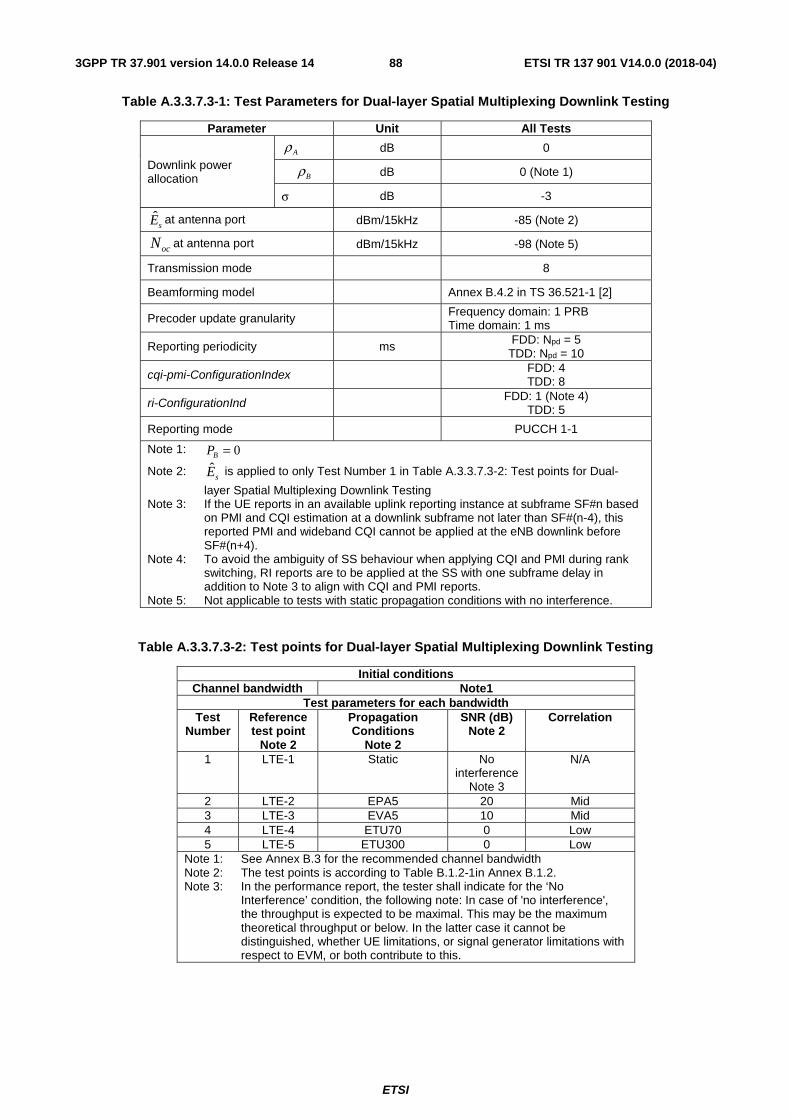
ETSI
ETSI TR 137 901 V14.0.0 (2018-04)883GPP TR 37.901 version 14.0.0 Release 14
Table A.3.3.7.3-1: Test Parameters for Dual-layer Spatial Multiplexing Downlink Testing
Parameter Unit All Tests
Downlink power allocation
dB 0
dB 0 (Note 1)
σ dB -3
sE at antenna port
dBm/15kHz -85 (Note 2)
at antenna port dBm/15kHz -98 (Note 5)
Transmission mode
8
Beamforming model Annex B.4.2 in TS 36.521-1 [2]
Precoder update granularity Frequency domain: 1 PRB Time domain: 1 ms
Reporting periodicity ms FDD: Npd = 5 TDD: Npd = 10
cqi-pmi-ConfigurationIndex FDD: 4 TDD: 8
ri-ConfigurationInd FDD: 1 (Note 4) TDD: 5
Reporting mode
PUCCH 1-1
Note 1: 0=BP
Note 2: sE is applied to only Test Number 1 in Table A.3.3.7.3-2: Test points for Dual-
layer Spatial Multiplexing Downlink Testing Note 3: If the UE reports in an available uplink reporting instance at subframe SF#n based
on PMI and CQI estimation at a downlink subframe not later than SF#(n-4), this reported PMI and wideband CQI cannot be applied at the eNB downlink before SF#(n+4).
Note 4: To avoid the ambiguity of SS behaviour when applying CQI and PMI during rank switching, RI reports are to be applied at the SS with one subframe delay in addition to Note 3 to align with CQI and PMI reports.
Note 5: Not applicable to tests with static propagation conditions with no interference.
Table A.3.3.7.3-2: Test points for Dual-layer Spatial Multiplexing Downlink Testing
Initial conditions Channel bandwidth Note1
Test parameters for each bandwidth Test
Number Reference test point
Note 2
Propagation Conditions
Note 2
SNR (dB) Note 2
Correlation
1 LTE-1 Static No interference
Note 3
N/A
2 LTE-2 EPA5 20 Mid 3 LTE-3 EVA5 10 Mid 4 LTE-4 ETU70 0 Low 5 LTE-5 ETU300 0 Low
Note 1: See Annex B.3 for the recommended channel bandwidth Note 2: The test points is according to Table B.1.2-1in Annex B.1.2. Note 3: In the performance report, the tester shall indicate for the ‘No
Interference’ condition, the following note: In case of 'no interference', the throughput is expected to be maximal. This may be the maximum theoretical throughput or below. In the latter case it cannot be distinguished, whether UE limitations, or signal generator limitations with respect to EVM, or both contribute to this.
Aρ
Bρ
ocN
ETSI
ETSI TR 137 901 V14.0.0 (2018-04)893GPP TR 37.901 version 14.0.0 Release 14
A.3.3.7.4 Test Description
A.3.3.7.4.1 Initial Conditions
Initial conditions are a set of test configurations the UE needs to be tested in and the steps for the SS to take with the UE to reach the correct measurement state.
Configurations of PDSCH and PDCCH before measurement are specified in Annex C.2 of TS 36.521-1 [2].
Test Environment: Normal, as defined in TS 36.508 [11] clause 4.1.
Frequencies to be tested: Mid Range, as defined in TS 36.508 [11] clause 4.3.1.2.
1) Connect the SS, the faders and AWGN noise sources to the UE antenna connectors as shown in TS 36.508 [11] Annex A, Figure A.10 for antenna configuration 2x2.
2) Connect an application server to the IP output of the SS configured with a UDP server.
3) For a tethered configuration, tether the UE to a laptop configured with UDP client software using the appropriate UE to PC interface Modem or Network Interface Connection (NIC) drivers. For an embedded configuration, ensure that the UE has an UDP client test application available.
4) The parameter settings for the cell are set up according to Tables A.3.1-3 and A.3.3.7.3-1 as appropriate.
5) Downlink signals are initially set up according to Annex C0, C.1 and Annex C.3.2 in TS 36.521-1 [2] and uplink signals according to Annex H.1 and H.3.2 in TS 36.521-1 [2].
6) Propagation conditions are set according to Annex B.0 in TS 36.521-1 [2].
A.3.3.7.4.2 Procedure
1) SS transmits PDSCH via PDCCH DCI format 2B for C_RNTI to transmit the DL data using the transport format and transport block size determined based on UE reported CQI as described in sub-clause B.2.2.1.
2) Set the parameters of the bandwidth, MCS, reference channel, the propagation condition, the correlation matrix, antenna configuration and the SNR according to Table A.3.3.7.3-2, as appropriate.
3) Using the UDP client, begin UDP download from the application server of a file sufficient in size for the test duration outlined in Table A.3.1-1 and record Throughput T result. (This is iteration 1)
4) Repeat transfer for iterations 2-5 within the same call as the first iteration.
5) Calculate and record the average throughput of the five iterations.
6) Count and record the overall number of ACK and NACK/DTX on the PUSCH/PUCCH during the test interval.
7) If the RRC connection setup needs to be re-established after the subtest, perform the initial call setup in accordance with the initial conditions in clause A.3.3.7.4.1.
8) Repeat steps 1 to 6 for each subtest in Table A.3.3.7.3-2, as appropriate.
9) Record the IP address type (IPv4 or IPv6) used during the file transfers.
A.3.4 LTE / FTP Uplink Performance
A.3.4.1 LTE / FTP Uplink / PUSCH Single Antenna Port Performance
A.3.4.1.1 Definition
The UE application layer uplink performance for FTP under Static environment is determined by the UE application layer FTP throughput T.
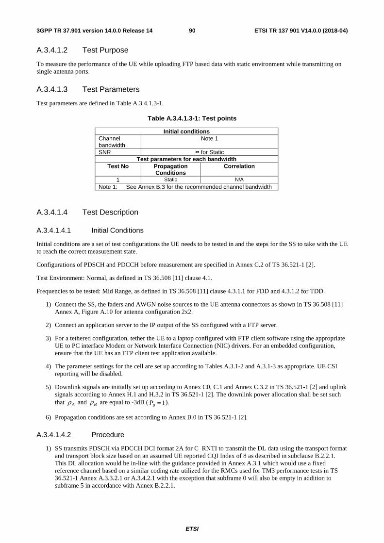
ETSI
ETSI TR 137 901 V14.0.0 (2018-04)903GPP TR 37.901 version 14.0.0 Release 14
A.3.4.1.2 Test Purpose
To measure the performance of the UE while uploading FTP based data with static environment while transmitting on single antenna ports.
A.3.4.1.3 Test Parameters
Test parameters are defined in Table A.3.4.1.3-1.
Table A.3.4.1.3-1: Test points
Initial conditions Channel bandwidth
Note 1
SNR ∞ for Static Test parameters for each bandwidth
Test No Propagation Conditions
Correlation
1 Static N/A
Note 1: See Annex B.3 for the recommended channel bandwidth
A.3.4.1.4 Test Description
A.3.4.1.4.1 Initial Conditions
Initial conditions are a set of test configurations the UE needs to be tested in and the steps for the SS to take with the UE to reach the correct measurement state.
Configurations of PDSCH and PDCCH before measurement are specified in Annex C.2 of TS 36.521-1 [2].
Test Environment: Normal, as defined in TS 36.508 [11] clause 4.1.
Frequencies to be tested: Mid Range, as defined in TS 36.508 [11] clause 4.3.1.1 for FDD and 4.3.1.2 for TDD.
1) Connect the SS, the faders and AWGN noise sources to the UE antenna connectors as shown in TS 36.508 [11] Annex A, Figure A.10 for antenna configuration 2x2.
2) Connect an application server to the IP output of the SS configured with a FTP server.
3) For a tethered configuration, tether the UE to a laptop configured with FTP client software using the appropriate UE to PC interface Modem or Network Interface Connection (NIC) drivers. For an embedded configuration, ensure that the UE has an FTP client test application available.
4) The parameter settings for the cell are set up according to Tables A.3.1-2 and A.3.1-3 as appropriate. UE CSI reporting will be disabled.
5) Downlink signals are initially set up according to Annex C0, C.1 and Annex C.3.2 in TS 36.521-1 [2] and uplink signals according to Annex H.1 and H.3.2 in TS 36.521-1 [2]. The downlink power allocation shall be set such that Aρ and Bρ are equal to -3dB ( ).
6) Propagation conditions are set according to Annex B.0 in TS 36.521-1 [2].
A.3.4.1.4.2 Procedure
1) SS transmits PDSCH via PDCCH DCI format 2A for C_RNTI to transmit the DL data using the transport format and transport block size based on an assumed UE reported CQI Index of 8 as described in subclause B.2.2.1. This DL allocation would be in-line with the guidance provided in Annex A.3.1 which would use a fixed reference channel based on a similar coding rate utilized for the RMCs used for TM3 performance tests in TS 36.521-1 Annex A.3.3.2.1 or A.3.4.2.1 with the exception that subframe 0 will also be empty in addition to subframe 5 in accordance with Annex B.2.2.1.
1=BP
ETSI
ETSI TR 137 901 V14.0.0 (2018-04)913GPP TR 37.901 version 14.0.0 Release 14
2) Set the downlink parameters of the bandwidth, the propagation condition, the correlation matrix, and the SNR according to Table A.3.4.1.3-1, as appropriate. Set the uplink parameters of the bandwidth, MCS, reference channel according to Annex A.3.1 as appropriate.
3) Using the FTP client, begin FTP upload from the application server of a file sufficient in size for the test duration outlined in Table A.3.1-1 and record Throughput T result. (This is iteration 1)
4) Repeat transfer for iterations 2-5 within the same call as the first iteration.
5) Calculate and record the average throughput of the five iterations.
6) Count and record the overall number of ACK and NACK on the PHICH during the test interval.
7) If the RRC connection setup needs to be re-established after the subtest, perform the initial call setup in accordance with the initial conditions in clause A.3.4.1.4.1.
8) Repeat steps 1 to 6 for each subtest in Table A.3.4.1.3-1, as appropriate.
9) Record the IP address type (IPv4 or IPv6) used during the file transfers.
A.3.5 LTE / UDP Uplink Performance
A.3.5.1 LTE / UDP Uplink / PUSCH Single Antenna Port Performance
A.3.5.1.1 Definition
The UE application layer uplink performance for UDP under Static environment is determined by the UE application layer UDP throughput T.
A.3.5.1.2 Test Purpose
To measure the performance of the UE while uploading UDP based data with static environment while transmitting on single antenna ports.
A.3.5.1.3 Test Parameters
Test parameters are defined in Table A.3.5.1.3-1.
Table A.3.5.1.3-1: Test points
Initial conditions Channel bandwidth
Note 1
SNR ∞ for Static Test parameters for each bandwidth
Test No Propagation Conditions
Correlation
1 Static N/A
Note 1: See Annex B.3 for the recommended channel bandwidth
A.3.5.1.4 Test Description
A.3.5.1.4.1 Initial Conditions
Initial conditions are a set of test configurations the UE needs to be tested in and the steps for the SS to take with the UE to reach the correct measurement state.
Configurations of PDSCH and PDCCH before measurement are specified in Annex C.2 of TS 36.521-1 [2].
Test Environment: Normal, as defined in TS 36.508 [11] clause 4.1.
ETSI
ETSI TR 137 901 V14.0.0 (2018-04)923GPP TR 37.901 version 14.0.0 Release 14
Frequencies to be tested: Mid Range, as defined in TS 36.508 [11] clause 4.3.1.1 for FDD and 4.3.1.2 for TDD.
1) Connect the SS, the faders and AWGN noise sources to the UE antenna connectors as shown in TS 36.508 [11] Annex A, Figure A.10 for antenna configuration 2x2.
2) Connect an application server to the IP output of the SS configured with a UDP server.
3) For a tethered configuration, tether the UE to a laptop configured with UDP client software using the appropriate UE to PC interface Modem or Network Interface Connection (NIC) drivers. For an embedded configuration, ensure that the UE has an UDP client test application available.
4) The parameter settings for the cell are set up according to Tables A.3.1-2 and A.3.1-3 as appropriate. UE CSI reporting will be disabled.
5) Downlink signals are initially set up according to Annex C0, C.1 and Annex C.3.2 in TS 36.521-1 [2] and uplink signals according to Annex H.1 and H.3.2 in TS 36.521-1 [2]. The downlink power allocation shall be set such that Aρ and Bρ are equal to -3dB ( ).
6) Propagation conditions are set according to Annex B.0 in TS 36.521-1 [2].
A.3.5.1.4.2 Procedure
1) SS transmits PDSCH via PDCCH DCI format 2A for C_RNTI to transmit the DL data using the transport format and transport block size based on an assumed UE reported CQI Index of 8 as described in subclause B.2.2.1. This DL allocation would be in-line with the guidance provided in Annex A.3.1 which would use a fixed reference channel based on a similar coding rate utilized for the RMCs used for TM3 performance tests in TS 36.521-1 Annex A.3.3.2.1 or A.3.4.2.1 with the exception that subframe 0 will also be empty in addition to subframe 5 in accordance with Annex B.2.2.1.
2) Set the downlink parameters of the bandwidth, the propagation condition, the correlation matrix, and the SNR according to Table A.3.5.1.3-1, as appropriate. Set the uplink parameters of the bandwidth, MCS, reference channel according to Annex A.3.1 as appropriate.
3) Using the UDP client, begin UDP upload from the application server of a file sufficient in size for the test duration outlined in Table A.3.1-1 and record Throughput T result. (This is iteration 1)
4) Repeat transfer for iterations 2-5 within the same call as the first iteration.
5) Calculate and record the average throughput of the five iterations.
6) Count and record the overall number of ACK and NACK on the PHICH during the test interval.
7) If the RRC connection setup needs to be re-established after the subtest, perform the initial call setup in accordance with the initial conditions in clause A.3.5.1.4.1.
8) Repeat steps 1 to 6 for each subtest in Table A.3.5.1.3-1, as appropriate.
9) Record the IP address type (IPv4 or IPv6) used during the file transfers.
A.3.6 LTE / Stress Test Performance
A.3.6.1 LTE / Stress Test Performance / PDSCH Transmit Diversity Performance (Cell-Specific Reference Symbols)
A.3.6.1.1 Definition
The UE application layer stress test performance is determined by the UE application layer bi-directional UDP and alternating direction FTP throughput T over an extended transfer duration.
1=BP
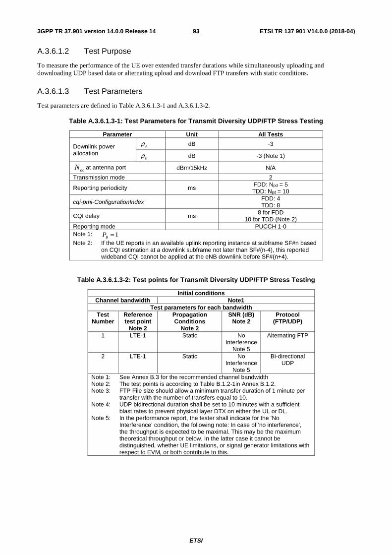
ETSI
ETSI TR 137 901 V14.0.0 (2018-04)933GPP TR 37.901 version 14.0.0 Release 14
A.3.6.1.2 Test Purpose
To measure the performance of the UE over extended transfer durations while simultaneously uploading and downloading UDP based data or alternating upload and download FTP transfers with static conditions.
A.3.6.1.3 Test Parameters
Test parameters are defined in Table A.3.6.1.3-1 and A.3.6.1.3-2.
Table A.3.6.1.3-1: Test Parameters for Transmit Diversity UDP/FTP Stress Testing
Parameter Unit All Tests
Downlink power allocation
dB -3
dB -3 (Note 1)
at antenna port dBm/15kHz N/A
Transmission mode
2
Reporting periodicity
ms FDD: Npd = 5 TDD: Npd = 10
cqi-pmi-ConfigurationIndex FDD: 4 TDD: 8
CQI delay
ms 8 for FDD
10 for TDD (Note 2) Reporting mode
PUCCH 1-0
Note 1: Note 2: If the UE reports in an available uplink reporting instance at subframe SF#n based
on CQI estimation at a downlink subframe not later than SF#(n-4), this reported wideband CQI cannot be applied at the eNB downlink before SF#(n+4).
Table A.3.6.1.3-2: Test points for Transmit Diversity UDP/FTP Stress Testing
Initial conditions Channel bandwidth Note1
Test parameters for each bandwidth Test
Number Reference test point
Note 2
Propagation Conditions
Note 2
SNR (dB) Note 2
Protocol (FTP/UDP)
1 LTE-1 Static No Interference
Note 5
Alternating FTP
2 LTE-1 Static No Interference
Note 5
Bi-directional UDP
Note 1: See Annex B.3 for the recommended channel bandwidth Note 2: The test points is according to Table B.1.2-1in Annex B.1.2. Note 3: FTP File size should allow a minimum transfer duration of 1 minute per
transfer with the number of transfers equal to 10. Note 4: UDP bidirectional duration shall be set to 10 minutes with a sufficient
blast rates to prevent physical layer DTX on either the UL or DL. Note 5: In the performance report, the tester shall indicate for the ‘No
Interference’ condition, the following note: In case of 'no interference', the throughput is expected to be maximal. This may be the maximum theoretical throughput or below. In the latter case it cannot be distinguished, whether UE limitations, or signal generator limitations with respect to EVM, or both contribute to this.
Aρ
Bρ
ocN
1=BP
ETSI
ETSI TR 137 901 V14.0.0 (2018-04)943GPP TR 37.901 version 14.0.0 Release 14
A.3.6.1.4 Test Description
A.3.6.1.4.1 Initial Conditions
Initial conditions are a set of test configurations the UE needs to be tested in and the steps for the SS to take with the UE to reach the correct measurement state.
Configurations of PDSCH and PDCCH before measurement are specified in Annex C.2 of TS 36.521-1 [2].
Test Environment: Normal, as defined in TS 36.508 [11] clause 4.1.
Frequencies to be tested: Mid Range, as defined in TS 36.508 [11] clause 4.3.1.1 for FDD and 4.3.1.2 for TDD.
1) Connect the SS, the faders and AWGN noise sources to the UE antenna connectors as shown in TS 36.508 [11] Annex A, Figure A.10 for antenna configuration 2x2.
2) Connect an application server to the IP output of the SS configured with both a FTP and UDP server.
3) For a tethered configuration, tether the UE to a laptop configured with both FTP and UDP client software using the appropriate UE to PC interface Modem or Network Interface Connection (NIC) drivers. For an embedded configuration, ensure that the UE has both FTP and UDP client test applications available.
4) The parameter settings for the cell are set up according to Tables A.3.1-2, A.3.1-3 and A.3.6.1.3-1 as appropriate.
5) Downlink signals are initially set up according to Annex C0, C.1 and Annex C.3.2 in TS 36.521-1 [2] and uplink signals according to Annex H.1 and H.3.2 in TS 36.521-1 [2].
6) Propagation conditions are set according to Annex B.0 in TS 36.521-1 [2].
A.3.6.1.4.2 Procedure
1) SS transmits PDSCH via PDCCH DCI format 1A for C_RNTI to transmit the DL data using the transport format and transport block size determined based on UE reported CQI as described in subclause B.2.2.1.
2) Set the downlink parameters of the bandwidth, propagation condition, and SNR according to Table A.3.6.1.3-2, as appropriate. Set the UL parameters of the bandwidth, MCS, reference channel according to Annex A.3.1 as appropriate.
3) Using the FTP or UDP client, begin FTP or UDP transfers to/from the application server per Table A.3.6.1.3-2 and record Throughput T results.
4) Record the overall number of ACK and NACK/DTX on the PUSCH/PUCCH during the test interval.
5) If the RRC connection setup needs to be re-established after the subtest, perform the initial call setup in accordance with the initial conditions in clause A.3.6.1.4.1.
6) Repeat steps 1 to 5 for each subtest in Table A.3.6.1.3-2, as appropriate.
7) Record the IP address type (IPv4 or IPv6) used during the file transfers.
A.3.6.2 LTE / Stress Test Performance / PDSCH Open Loop Spatial Multiplexing Performance (Cell-Specific Reference Symbols)
A.3.6.2.1 Definition
The UE application layer stress test performance is determined by the UE application layer bi-directional UDP and alternating direction FTP throughput T over an extended transfer duration.
A.3.6.2.2 Test Purpose
To measure the performance of the UE over extended transfer durations while simultaneously uploading and downloading UDP based data or alternating upload and download FTP transfers with static conditions.
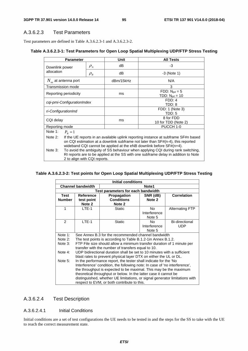
ETSI
ETSI TR 137 901 V14.0.0 (2018-04)953GPP TR 37.901 version 14.0.0 Release 14
A.3.6.2.3 Test Parameters
Test parameters are defined in Table A.3.6.2.3-1 and A.3.6.2.3-2.
Table A.3.6.2.3-1: Test Parameters for Open Loop Spatial Multiplexing UDP/FTP Stress Testing
Parameter Unit All Tests
Downlink power allocation
dB -3
dB -3 (Note 1)
at antenna port dBm/15kHz N/A
Transmission mode
3
Reporting periodicity
ms FDD: Npd = 5 TDD: Npd = 10
cqi-pmi-ConfigurationIndex FDD: 4 TDD: 8
ri-ConfigurationInd FDD: 1 (Note 3) TDD: 5
CQI delay
ms 8 for FDD 10 for TDD (Note 2)
Reporting mode
PUCCH 1-0 Note 1: Note 2: If the UE reports in an available uplink reporting instance at subframe SF#n based
on CQI estimation at a downlink subframe not later than SF#(n-4), this reported wideband CQI cannot be applied at the eNB downlink before SF#(n+4).
Note 3: To avoid the ambiguity of SS behaviour when applying CQI during rank switching, RI reports are to be applied at the SS with one subframe delay in addition to Note 2 to align with CQI reports.
Table A.3.6.2.3-2: Test points for Open Loop Spatial Multiplexing UDP/FTP Stress Testing
Initial conditions Channel bandwidth Note1
Test parameters for each bandwidth Test
Number Reference test point
Note 2
Propagation Conditions
Note 2
SNR (dB) Note 2
Correlation
1 LTE-1 Static No Interference
Note 5
Alternating FTP
2 LTE-1 Static No Interference
Note 5
Bi-directional UDP
Note 1: See Annex B.3 for the recommended channel bandwidth Note 2: The test points is according to Table B.1.2-1in Annex B.1.2. Note 3: FTP File size should allow a minimum transfer duration of 1 minute per
transfer with the number of transfers equal to 10. Note 4: UDP bidirectional duration shall be set to 10 minutes with a sufficient
blast rates to prevent physical layer DTX on either the UL or DL. Note 5: In the performance report, the tester shall indicate for the ‘No
Interference’ condition, the following note: In case of 'no interference', the throughput is expected to be maximal. This may be the maximum theoretical throughput or below. In the latter case it cannot be distinguished, whether UE limitations, or signal generator limitations with respect to EVM, or both contribute to this.
A.3.6.2.4 Test Description
A.3.6.2.4.1 Initial Conditions
Initial conditions are a set of test configurations the UE needs to be tested in and the steps for the SS to take with the UE to reach the correct measurement state.
Aρ
Bρ
ocN
1=BP
ETSI
ETSI TR 137 901 V14.0.0 (2018-04)963GPP TR 37.901 version 14.0.0 Release 14
Configurations of PDSCH and PDCCH before measurement are specified in Annex C.2 of TS 36.521-1 [2].
Test Environment: Normal, as defined in TS 36.508 [11] clause 4.1.
Frequencies to be tested: Mid Range, as defined in TS 36.508 [11] clause 4.3.1.1 for FDD and 4.3.1.2 for TDD.
1) Connect the SS, the faders and AWGN noise sources to the UE antenna connectors as shown in TS 36.508 [11] Annex A, Figure A.10 for antenna configuration 2x2.
2) Connect an application server to the IP output of the SS configured with both a FTP and UDP server.
3) For a tethered configuration, tether the UE to a laptop configured with both FTP and UDP client software using the appropriate UE to PC interface Modem or Network Interface Connection (NIC) drivers. For an embedded configuration, ensure that the UE has both FTP and UDP client test applications available.
4) The parameter settings for the cell are set up according to Tables A.3.1-2, A.3.1-3 and A.3.6.2.3-1 as appropriate.
5) Downlink signals are initially set up according to Annex C0, C.1 and Annex C.3.2 in TS 36.521-1 [2] and uplink signals according to Annex H.1 and H.3.2 in TS 36.521-1 [2].
6) Propagation conditions are set according to Annex B.0 in TS 36.521-1 [2].
A.3.6.2.4.2 Procedure
1) SS transmits PDSCH via PDCCH DCI format 2A for C_RNTI to transmit the DL data using the transport format and transport block size determined based on UE reported CQI as described in subclause B.2.2.1.
2) Set the downlink parameters of the bandwidth, propagation condition, and SNR according to Table A.3.6.2.3-2, as appropriate. Set the UL parameters of the bandwidth, MCS, reference channel according to Annex A.3.1 as appropriate.
3) Using the FTP or UDP client, begin FTP or UDP transfers to/from the application server per Table A.3.6.2.3-2 and record Throughput T results.
4) Record the overall number of ACK and NACK/DTX on the PUSCH/PUCCH during the test interval.
5) If the RRC connection setup needs to be re-established after the subtest, perform the initial call setup in accordance with the initial conditions in clause A.3.6.2.4.1.
6) Repeat steps 1 to 5 for each subtest in Table A.3.6.2.3-2, as appropriate.
7) Record the IP address type (IPv4 or IPv6) used during the file transfers.
A.3.7 LTE / UDP Power Sweep Performance
A.3.7.1 LTE / UDP Power Sweep Performance / PDSCH Transmit Diversity Performance (Cell-Specific Reference Symbols)
A.3.7.1.1 Definition
The UE application layer power sweep performance for UDP under a multi-path fading environment is determined by the UE application layer UDP throughput T.
A.3.7.1.2 Test Purpose
To determine if the UE Application Layer Data Throughput increases as the signal level is increased in relation to the UE noise floor and the consistency of the UE Application Layer Data Throughput across Channel BW Power values once the throughput has reached a maximum while downloading UDP based data with a multi path faded environment.
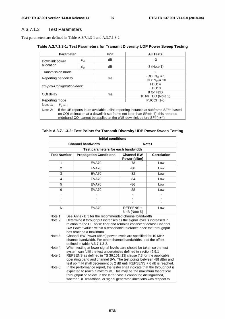
ETSI
ETSI TR 137 901 V14.0.0 (2018-04)973GPP TR 37.901 version 14.0.0 Release 14
A.3.7.1.3 Test Parameters
Test parameters are defined in Table A.3.7.1.3-1 and A.3.7.1.3-2.
Table A.3.7.1.3-1: Test Parameters for Transmit Diversity UDP Power Sweep Testing
Parameter Unit All Tests
Downlink power allocation
dB -3
dB -3 (Note 1)
Transmission mode
2
Reporting periodicity
ms FDD: Npd = 5 TDD: Npd = 10
cqi-pmi-ConfigurationIndex FDD: 4 TDD: 8
CQI delay
ms 8 for FDD 10 for TDD (Note 2)
Reporting mode
PUCCH 1-0 Note 1: Note 2: If the UE reports in an available uplink reporting instance at subframe SF#n based
on CQI estimation at a downlink subframe not later than SF#(n-4), this reported wideband CQI cannot be applied at the eNB downlink before SF#(n+4).
Table A.3.7.1.3-2: Test Points for Transmit Diversity UDP Power Sweep Testing
Initial conditions
Channel bandwidth Note1
Test parameters for each bandwidth
Test Number Propagation Conditions Channel BW Power (dBm)
Correlation
1 EVA70 -78 Low
2 EVA70 -80 Low
3 EVA70 -82 Low
4 EVA70 -84 Low
5 EVA70 -86 Low
6 . . .
EVA70 . . .
-88 . . .
Low . . .
N EVA70 REFSENS + 6 dB [Note 5]
Low
Note 1: See Annex B.3 for the recommended channel bandwidth Note 2: Determine if throughput increases as the signal level is increased in
relation to the UE noise floor and remains consistent across Channel BW Power values within a reasonable tolerance once the throughput has reached a maximum.
Note 3: Channel BW Power (dBm) power levels are specified for 10 MHz channel bandwidth. For other channel bandwidths, add the offset defined in table A.3.7.1.3-3.
Note 4: When testing at lower signal levels care should be taken so the test system can fulfil the test uncertainties defined in section 5.9.1
Note 5: REFSENS as defined in TS 36.101 [13] clause 7.3 for the applicable operating band and channel BW. The test points between -88 dBm and test point N shall decrement by 2 dB until REFSENS + 6 dB is reached.
Note 6: In the performance report, the tester shall indicate that the throughput is expected to reach a maximum. This may be the maximum theoretical throughput or below. In the latter case it cannot be distinguished, whether UE limitations, or signal generator limitations with respect to EVM, or both contribute to this.
Aρ
Bρ
1=BP
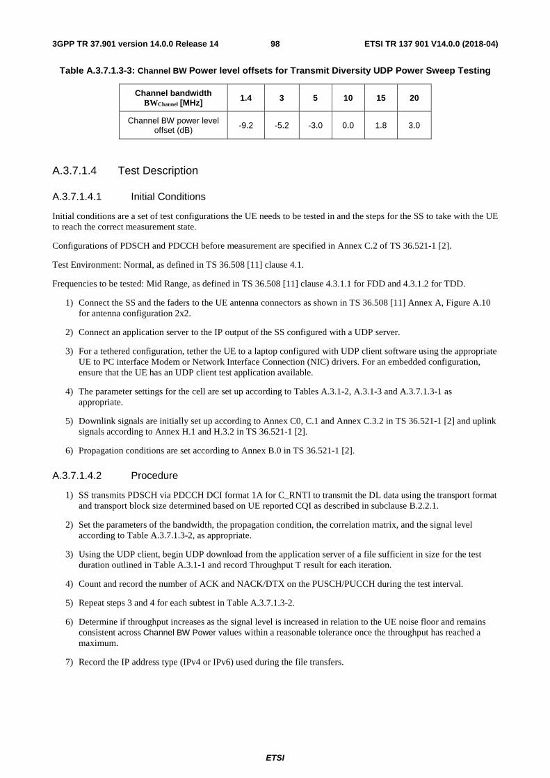
ETSI
ETSI TR 137 901 V14.0.0 (2018-04)983GPP TR 37.901 version 14.0.0 Release 14
Table A.3.7.1.3-3: Channel BW Power level offsets for Transmit Diversity UDP Power Sweep Testing
Channel bandwidth BWChannel [MHz] 1.4 3 5 10 15 20
Channel BW power level offset (dB) -9.2 -5.2 -3.0 0.0 1.8 3.0
A.3.7.1.4 Test Description
A.3.7.1.4.1 Initial Conditions
Initial conditions are a set of test configurations the UE needs to be tested in and the steps for the SS to take with the UE to reach the correct measurement state.
Configurations of PDSCH and PDCCH before measurement are specified in Annex C.2 of TS 36.521-1 [2].
Test Environment: Normal, as defined in TS 36.508 [11] clause 4.1.
Frequencies to be tested: Mid Range, as defined in TS 36.508 [11] clause 4.3.1.1 for FDD and 4.3.1.2 for TDD.
1) Connect the SS and the faders to the UE antenna connectors as shown in TS 36.508 [11] Annex A, Figure A.10 for antenna configuration 2x2.
2) Connect an application server to the IP output of the SS configured with a UDP server.
3) For a tethered configuration, tether the UE to a laptop configured with UDP client software using the appropriate UE to PC interface Modem or Network Interface Connection (NIC) drivers. For an embedded configuration, ensure that the UE has an UDP client test application available.
4) The parameter settings for the cell are set up according to Tables A.3.1-2, A.3.1-3 and A.3.7.1.3-1 as appropriate.
5) Downlink signals are initially set up according to Annex C0, C.1 and Annex C.3.2 in TS 36.521-1 [2] and uplink signals according to Annex H.1 and H.3.2 in TS 36.521-1 [2].
6) Propagation conditions are set according to Annex B.0 in TS 36.521-1 [2].
A.3.7.1.4.2 Procedure
1) SS transmits PDSCH via PDCCH DCI format 1A for C_RNTI to transmit the DL data using the transport format and transport block size determined based on UE reported CQI as described in subclause B.2.2.1.
2) Set the parameters of the bandwidth, the propagation condition, the correlation matrix, and the signal level according to Table A.3.7.1.3-2, as appropriate.
3) Using the UDP client, begin UDP download from the application server of a file sufficient in size for the test duration outlined in Table A.3.1-1 and record Throughput T result for each iteration.
4) Count and record the number of ACK and NACK/DTX on the PUSCH/PUCCH during the test interval.
5) Repeat steps 3 and 4 for each subtest in Table A.3.7.1.3-2.
6) Determine if throughput increases as the signal level is increased in relation to the UE noise floor and remains consistent across Channel BW Power values within a reasonable tolerance once the throughput has reached a maximum.
7) Record the IP address type (IPv4 or IPv6) used during the file transfers.
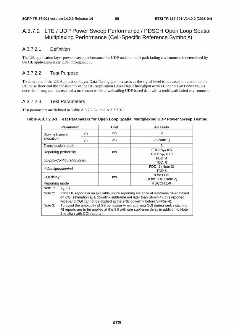
ETSI
ETSI TR 137 901 V14.0.0 (2018-04)993GPP TR 37.901 version 14.0.0 Release 14
A.3.7.2 LTE / UDP Power Sweep Performance / PDSCH Open Loop Spatial Multiplexing Performance (Cell-Specific Reference Symbols)
A.3.7.2.1 Definition
The UE application layer power sweep performance for UDP under a multi-path fading environment is determined by the UE application layer UDP throughput T.
A.3.7.2.2 Test Purpose
To determine if the UE Application Layer Data Throughput increases as the signal level is increased in relation to the UE noise floor and the consistency of the UE Application Layer Data Throughput across Channel BW Power values once the throughput has reached a maximum while downloading UDP based data with a multi path faded environment.
A.3.7.2.3 Test Parameters
Test parameters are defined in Table A.3.7.2.3-1 and A.3.7.2.3-2.
Table A.3.7.2.3-1: Test Parameters for Open Loop Spatial Multiplexing UDP Power Sweep Testing
Parameter Unit All Tests
Downlink power allocation
dB -3
dB -3 (Note 1)
Transmission mode
3
Reporting periodicity
ms FDD: Npd = 5 TDD: Npd = 10
cqi-pmi-ConfigurationIndex FDD: 4 TDD: 8
ri-ConfigurationInd FDD: 1 (Note 3)
TDD:5
CQI delay
ms 8 for FDD 10 for TDD (Note 2)
Reporting mode
PUCCH 1-0 Note 1: Note 2: If the UE reports in an available uplink reporting instance at subframe SF#n based
on CQI estimation at a downlink subframe not later than SF#(n-4), this reported wideband CQI cannot be applied at the eNB downlink before SF#(n+4).
Note 3: To avoid the ambiguity of SS behaviour when applying CQI during rank switching, RI reports are to be applied at the SS with one subframe delay in addition to Note 2 to align with CQI reports.
Aρ
Bρ
1=BP
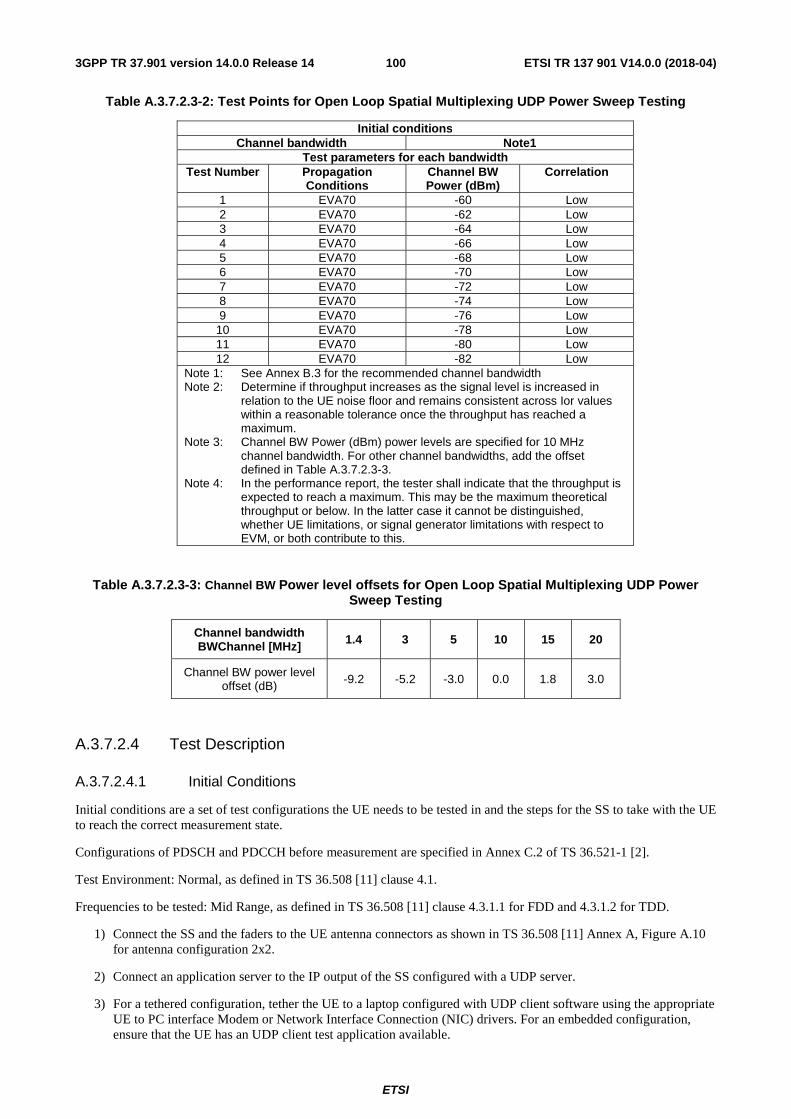
ETSI
ETSI TR 137 901 V14.0.0 (2018-04)1003GPP TR 37.901 version 14.0.0 Release 14
Table A.3.7.2.3-2: Test Points for Open Loop Spatial Multiplexing UDP Power Sweep Testing
Initial conditions Channel bandwidth Note1
Test parameters for each bandwidth Test Number Propagation
Conditions Channel BW Power (dBm)
Correlation
1 EVA70 -60 Low 2 EVA70 -62 Low 3 EVA70 -64 Low 4 EVA70 -66 Low 5 EVA70 -68 Low 6 EVA70 -70 Low 7 EVA70 -72 Low 8 EVA70 -74 Low 9 EVA70 -76 Low
10 EVA70 -78 Low 11 EVA70 -80 Low 12 EVA70 -82 Low
Note 1: See Annex B.3 for the recommended channel bandwidth Note 2: Determine if throughput increases as the signal level is increased in
relation to the UE noise floor and remains consistent across Ior values within a reasonable tolerance once the throughput has reached a maximum.
Note 3: Channel BW Power (dBm) power levels are specified for 10 MHz channel bandwidth. For other channel bandwidths, add the offset defined in Table A.3.7.2.3-3.
Note 4: In the performance report, the tester shall indicate that the throughput is expected to reach a maximum. This may be the maximum theoretical throughput or below. In the latter case it cannot be distinguished, whether UE limitations, or signal generator limitations with respect to EVM, or both contribute to this.
Table A.3.7.2.3-3: Channel BW Power level offsets for Open Loop Spatial Multiplexing UDP Power Sweep Testing
Channel bandwidth BWChannel [MHz] 1.4 3 5 10 15 20
Channel BW power level offset (dB) -9.2 -5.2 -3.0 0.0 1.8 3.0
A.3.7.2.4 Test Description
A.3.7.2.4.1 Initial Conditions
Initial conditions are a set of test configurations the UE needs to be tested in and the steps for the SS to take with the UE to reach the correct measurement state.
Configurations of PDSCH and PDCCH before measurement are specified in Annex C.2 of TS 36.521-1 [2].
Test Environment: Normal, as defined in TS 36.508 [11] clause 4.1.
Frequencies to be tested: Mid Range, as defined in TS 36.508 [11] clause 4.3.1.1 for FDD and 4.3.1.2 for TDD.
1) Connect the SS and the faders to the UE antenna connectors as shown in TS 36.508 [11] Annex A, Figure A.10 for antenna configuration 2x2.
2) Connect an application server to the IP output of the SS configured with a UDP server.
3) For a tethered configuration, tether the UE to a laptop configured with UDP client software using the appropriate UE to PC interface Modem or Network Interface Connection (NIC) drivers. For an embedded configuration, ensure that the UE has an UDP client test application available.
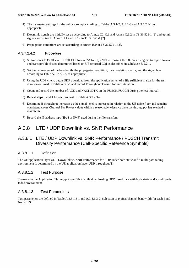
ETSI
ETSI TR 137 901 V14.0.0 (2018-04)1013GPP TR 37.901 version 14.0.0 Release 14
4) The parameter settings for the cell are set up according to Tables A.3.1-2, A.3.1-3 and A.3.7.2.3-1 as appropriate.
5) Downlink signals are initially set up according to Annex C0, C.1 and Annex C.3.2 in TS 36.521-1 [2] and uplink signals according to Annex H.1 and H.3.2 in TS 36.521-1 [2].
6) Propagation conditions are set according to Annex B.0 in TS 36.521-1 [2].
A.3.7.2.4.2 Procedure
1) SS transmits PDSCH via PDCCH DCI format 2A for C_RNTI to transmit the DL data using the transport format and transport block size determined based on UE reported CQI as described in subclause B.2.2.1.
2) Set the parameters of the bandwidth, the propagation condition, the correlation matrix, and the signal level according to Table A.3.7.2.3-2, as appropriate.
3) Using the UDP client, begin UDP download from the application server of a file sufficient in size for the test duration outlined in Table A.3.1-1 and record Throughput T result for each iteration.
4) Count and record the number of ACK and NACK/DTX on the PUSCH/PUCCH during the test interval.
5) Repeat steps 3 and 4 for each subtest in Table A.3.7.2.3-2.
6) Determine if throughput increases as the signal level is increased in relation to the UE noise floor and remains consistent across Channel BW Power values within a reasonable tolerance once the throughput has reached a maximum.
7) Record the IP address type (IPv4 or IPv6) used during the file transfers.
A.3.8 LTE / UDP Downlink vs. SNR Performance
A.3.8.1 LTE / UDP Downlink vs. SNR Performance / PDSCH Transmit Diversity Performance (Cell-Specific Reference Symbols)
A.3.8.1.1 Definition
The UE application layer UDP Downlink vs. SNR Performance for UDP under both static and a multi-path fading environment is determined by the UE application layer UDP throughput T.
A.3.8.1.2 Test Purpose
To measure the Application Throughput over SNR while downloading UDP based data with both static and a multi path faded environment.
A.3.8.1.3 Test Parameters
Test parameters are defined in Table A.3.8.1.3-1 and A.3.8.1.3-2. Selection of typical channel bandwidth for each Band No is FFS.
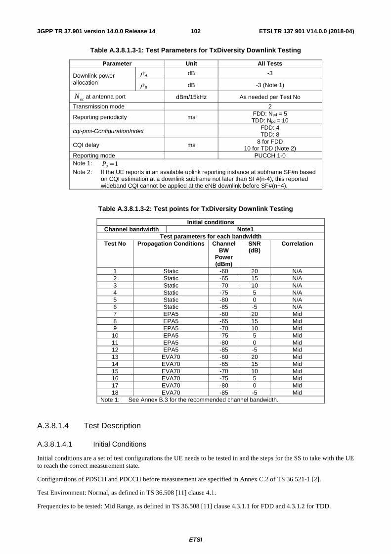
ETSI
ETSI TR 137 901 V14.0.0 (2018-04)1023GPP TR 37.901 version 14.0.0 Release 14
Table A.3.8.1.3-1: Test Parameters for TxDiversity Downlink Testing
Parameter Unit All Tests
Downlink power allocation
dB -3
dB -3 (Note 1)
at antenna port dBm/15kHz As needed per Test No
Transmission mode
2
Reporting periodicity
ms FDD: Npd = 5 TDD: Npd = 10
cqi-pmi-ConfigurationIndex FDD: 4 TDD: 8
CQI delay
ms 8 for FDD 10 for TDD (Note 2)
Reporting mode
PUCCH 1-0 Note 1: Note 2: If the UE reports in an available uplink reporting instance at subframe SF#n based
on CQI estimation at a downlink subframe not later than SF#(n-4), this reported wideband CQI cannot be applied at the eNB downlink before SF#(n+4).
Table A.3.8.1.3-2: Test points for TxDiversity Downlink Testing
Initial conditions Channel bandwidth Note1
Test parameters for each bandwidth Test No Propagation Conditions Channel
BW Power (dBm)
SNR (dB)
Correlation
1 Static -60 20 N/A 2 Static -65 15 N/A 3 Static -70 10 N/A 4 Static -75 5 N/A 5 Static -80 0 N/A 6 Static -85 -5 N/A 7 EPA5 -60 20 Mid 8 EPA5 -65 15 Mid 9 EPA5 -70 10 Mid
10 EPA5 -75 5 Mid 11 EPA5 -80 0 Mid 12 EPA5 -85 -5 Mid 13 EVA70 -60 20 Mid 14 EVA70 -65 15 Mid 15 EVA70 -70 10 Mid 16 EVA70 -75 5 Mid 17 EVA70 -80 0 Mid 18 EVA70 -85 -5 Mid
Note 1: See Annex B.3 for the recommended channel bandwidth.
A.3.8.1.4 Test Description
A.3.8.1.4.1 Initial Conditions
Initial conditions are a set of test configurations the UE needs to be tested in and the steps for the SS to take with the UE to reach the correct measurement state.
Configurations of PDSCH and PDCCH before measurement are specified in Annex C.2 of TS 36.521-1 [2].
Test Environment: Normal, as defined in TS 36.508 [11] clause 4.1.
Frequencies to be tested: Mid Range, as defined in TS 36.508 [11] clause 4.3.1.1 for FDD and 4.3.1.2 for TDD.
Aρ
Bρ
ocN
1=BP
ETSI
ETSI TR 137 901 V14.0.0 (2018-04)1033GPP TR 37.901 version 14.0.0 Release 14
1) Connect the SS, the faders and AWGN noise sources to the UE antenna connectors as shown in TS 36.508 [11] Annex A, Figure A.10 for antenna configuration 2x2.
2) Connect an application server to the IP output of the SS configured with a UDP server.
3) For a tethered configuration, tether the UE to a laptop configured with UDP client software using the appropriate UE to PC interface Modem or Network Interface Connection (NIC) drivers. For an embedded configuration, ensure that the UE has an UDP client test application available.
4) The parameter settings for the cell are set up according to Tables A.3.1-2, A.3.1-3 and A.3.8.1.3-1 as appropriate.
5) Downlink signals are initially set up according to Annex C0, C.1 and Annex C.3.2 in TS 36.521-1 [2] and uplink signals according to Annex H.1 and H.3.2 in TS 36.521-1 [2].
6) Propagation conditions are set according to Annex B.0 in TS 36.521-1 [2].
A.3.8.1.4.2 Procedure
1) SS transmits PDSCH via PDCCH DCI format 1A for C_RNTI to transmit the DL data using the transport format and transport block size determined based on UE reported CQI as described in subclause B.2.2.1.
2) Set the parameters of the bandwidth, reference channel, the propagation condition, the correlation matrix, antenna configuration and the SNR according to Table A.3.8.1.3-2, as appropriate.
3) Using the UDP client, begin UDP download from the application server of a file sufficient in size for the test duration outlined in Table A.3.1-1 and record Throughput T result
4) Count and record the overall number of ACK and NACK/DTX on the PUSCH/PUCCH during the subtest interval.
5) Repeat steps 3 and 4 for each subtest in Table A.3.8.1.3-2.
6) If the RRC connection setup needs to be re-established after the subtest, perform the initial call setup in accordance with the initial conditions in clause A.3.8.1.4.1.
7) Record the IP address type (IPv4 or IPv6) used during the file transfers.
A.3.8.2 LTE / UDP Downlink vs. SNR Performance / PDSCH Open Loop Spatial Multiplexing Performance (Cell-Specific Reference Symbols)
A.3.8.2.1 Definition
The UE application layer downlink performance for UDP under different multi-path fading environments is determined by the UE application layer UDP throughput T.
A.3.8.2.2 Test Purpose
To measure the performance of the UE while downloading UDP based data within both static and multi path faded environments.
A.3.8.2.3 Test Parameters
Test parameters are defined in Table A.3.8.2.3-1 and A.3.8.2.3-2.
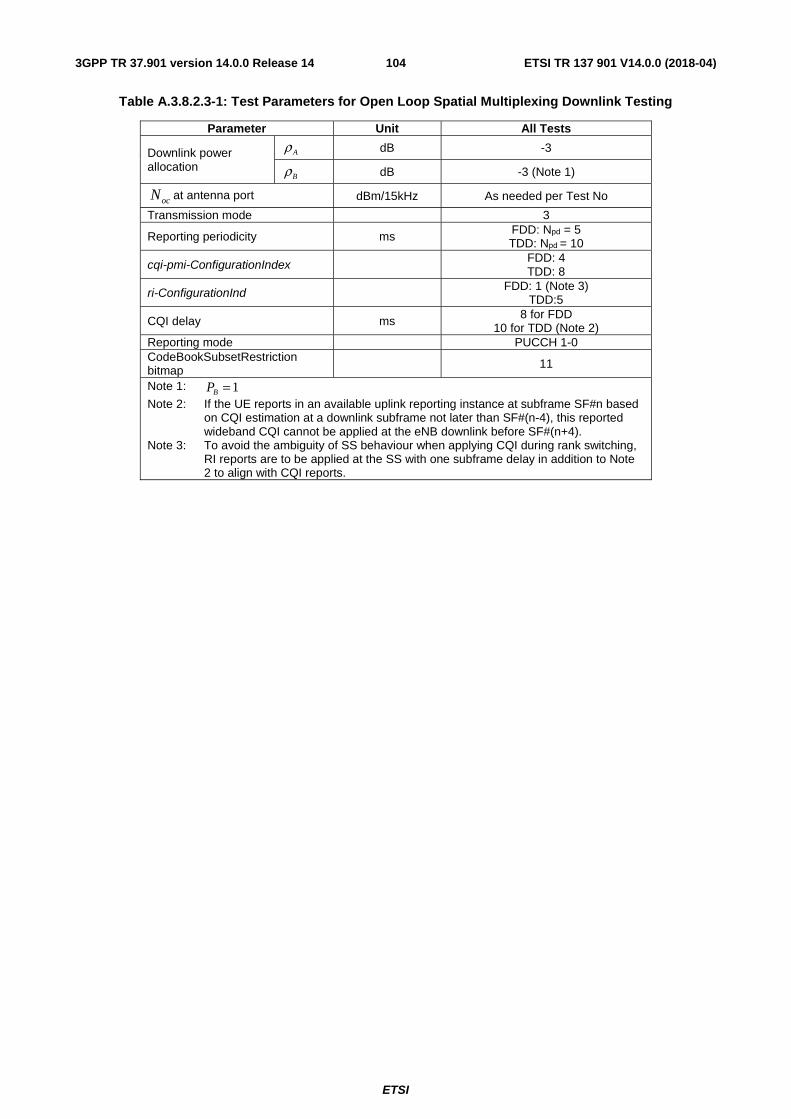
ETSI
ETSI TR 137 901 V14.0.0 (2018-04)1043GPP TR 37.901 version 14.0.0 Release 14
Table A.3.8.2.3-1: Test Parameters for Open Loop Spatial Multiplexing Downlink Testing
Parameter Unit All Tests
Downlink power allocation
dB -3
dB -3 (Note 1)
at antenna port dBm/15kHz As needed per Test No
Transmission mode
3
Reporting periodicity
ms FDD: Npd = 5 TDD: Npd = 10
cqi-pmi-ConfigurationIndex FDD: 4 TDD: 8
ri-ConfigurationInd FDD: 1 (Note 3) TDD:5
CQI delay
ms 8 for FDD 10 for TDD (Note 2)
Reporting mode
PUCCH 1-0 CodeBookSubsetRestriction bitmap 11
Note 1: Note 2: If the UE reports in an available uplink reporting instance at subframe SF#n based
on CQI estimation at a downlink subframe not later than SF#(n-4), this reported wideband CQI cannot be applied at the eNB downlink before SF#(n+4).
Note 3: To avoid the ambiguity of SS behaviour when applying CQI during rank switching, RI reports are to be applied at the SS with one subframe delay in addition to Note 2 to align with CQI reports.
Aρ
Bρ
ocN
1=BP

ETSI
ETSI TR 137 901 V14.0.0 (2018-04)1053GPP TR 37.901 version 14.0.0 Release 14
Table A.3.8.2.3-2: Test points for Open Loop Spatial Multiplexing Testing
Initial conditions Channel bandwidth Note1
Test parameters for each bandwidth Test No Propagation
Conditions Channel
BW Power (dBm)
SNR (dB) Correlation
1 Note 3
Static -50 No Interference
Note 2
N/A
2 Static -55 25 N/A 3 Static -60 20 N/A 4 Static -65 15 N/A 5 Static -70 10 N/A 6 Static -75 5 N/A 7 Static -80 0 N/A 8 EPA5 -50 No External
Noise Low
9 EPA5 -55 25 Low 10 EPA5 -60 20 Low 11 EPA5 -65 15 Low 12 EPA5 -70 10 Low 13 EPA5 -75 5 Low 14 EPA5 -80 0 Low 15 EVA70 -50 No External
Noise Low
16 EVA70 -55 25 Low 17 EVA70 -60 20 Low 18 EVA70 -65 15 Low 19 EVA70 -70 10 Low 20 EVA70 -75 5 Low 21 EVA70 -80 0 Low
Note 1: See Annex B.3 for the recommended channel bandwidth. Note 2: In the performance report, the tester shall indicate for the ‘No
Interference’ condition, the following note: In case of ‘No Interference’, the throughput is expected to be maximal. This may be the maximum theoretical throughput or below. In the latter case it cannot be distinguished, whether UE limitations, or signal generator limitations with respect to EVM, or both contribute to this.
Note 3: If this test point is part of another test there is no need to repeat. The previous result can be used.
A.3.8.2.4 Test Description
A.3.8.2.4.1 Initial Conditions
Initial conditions are a set of test configurations the UE needs to be tested in and the steps for the SS to take with the UE to reach the correct measurement state.
Configurations of PDSCH and PDCCH before measurement are specified in Annex C.2 of TS 36.521-1 [2].
Test Environment: Normal, as defined in TS 36.508 [11] clause 4.1.
Frequencies to be tested: Mid Range, as defined in TS 36.508 [11] clause 4.3.1.1 for FDD and 4.3.1.2 for TDD.
1) Connect the SS, the faders and AWGN noise sources to the UE antenna connectors as shown in TS 36.508 [11] Annex A, Figure A.10 for antenna configuration 2x2.
2) Connect an application server to the IP output of the SS configured with a UDP server.
ETSI
ETSI TR 137 901 V14.0.0 (2018-04)1063GPP TR 37.901 version 14.0.0 Release 14
3) For a tethered configuration, tether the UE to a laptop configured with UDP client software using the appropriate UE to PC interface Modem or Network Interface Connection (NIC) drivers. For an embedded configuration, ensure that the UE has an UDP client test application available.
4) The parameter settings for the cell are set up according to Tables A.3.1-2, A.3.1-3 and A.3.8.2.3-1 as appropriate.
5) Downlink signals are initially set up according to Annex C0, C.1 and Annex C.3.2 in TS 36.521-1 [2] and uplink signals according to Annex H.1 and H.3.2 in TS 36.521-1 [2].
6) Propagation conditions are set according to Annex B.0 in TS 36.521-1 [2].
A.3.8.2.4.2 Procedure
1) SS transmits PDSCH via PDCCH DCI format 2A for C_RNTI to transmit the DL data using the transport format and transport block size determined based on UE reported CQI as described in subclause B.2.2.1.
2) Set the parameters of the bandwidth, reference channel, the propagation condition, the correlation matrix, antenna configuration and the SNR according to Table A.3.8.2.3-2, as appropriate.
3) Using the UDP client, begin UDP download from the application server of a file sufficient in size for the test duration outlined in Table A.3.1-1 and record Throughput T result.
4) Count and record the overall number of ACK and NACK/DTX on the PUSCH/PUCCH during the subtest interval.
5) Repeat steps 3 and 4 for each subtest in Table A.3.8.2.3-2.
6) If the RRC connection setup needs to be re-established after the subtest, perform the initial call setup in accordance with the initial conditions in clause A.3.8.2.4.1.
7) Record the IP address type (IPv4 or IPv6) used during the file transfers.
A.3.8.3 LTE / UDP Downlink vs. SNR Performance / PDSCH Closed Loop Spatial Multiplexing Performance (Cell-Specific Reference Symbols)
A.3.8.3.1 Definition
The UE application layer downlink performance for UDP under different multi-path fading environments is determined by the UE application layer UDP throughput T.
A.3.8.3.2 Test Purpose
To measure the performance of the UE while downloading UDP based data within both static and multi path faded environments.
A.3.8.3.3 Test Parameters
Test parameters are defined in Table A.3.8.3.3-1 and A.3.8.3.3-2.
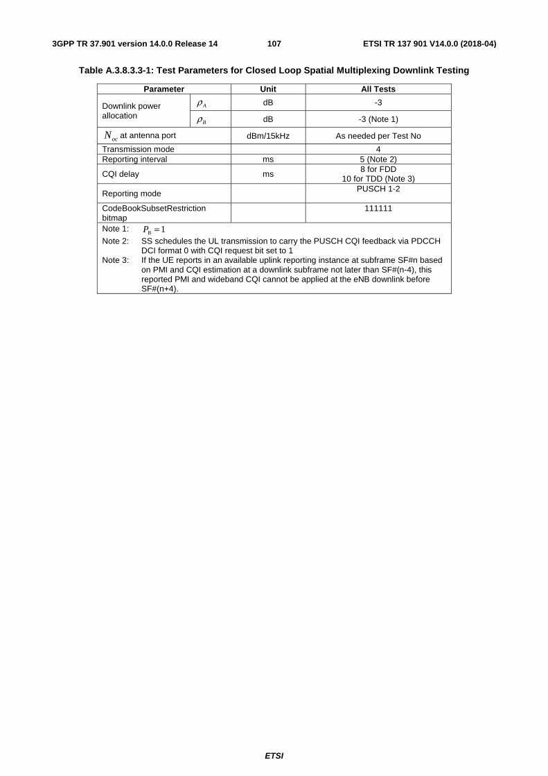
ETSI
ETSI TR 137 901 V14.0.0 (2018-04)1073GPP TR 37.901 version 14.0.0 Release 14
Table A.3.8.3.3-1: Test Parameters for Closed Loop Spatial Multiplexing Downlink Testing
Parameter Unit All Tests
Downlink power allocation
dB -3
dB -3 (Note 1)
at antenna port dBm/15kHz As needed per Test No
Transmission mode
4 Reporting interval
ms 5 (Note 2)
CQI delay
ms 8 for FDD 10 for TDD (Note 3)
Reporting mode
PUSCH 1-2
CodeBookSubsetRestriction bitmap
111111
Note 1: Note 2: SS schedules the UL transmission to carry the PUSCH CQI feedback via PDCCH
DCI format 0 with CQI request bit set to 1 Note 3: If the UE reports in an available uplink reporting instance at subframe SF#n based
on PMI and CQI estimation at a downlink subframe not later than SF#(n-4), this reported PMI and wideband CQI cannot be applied at the eNB downlink before SF#(n+4).
Aρ
Bρ
ocN
1=BP
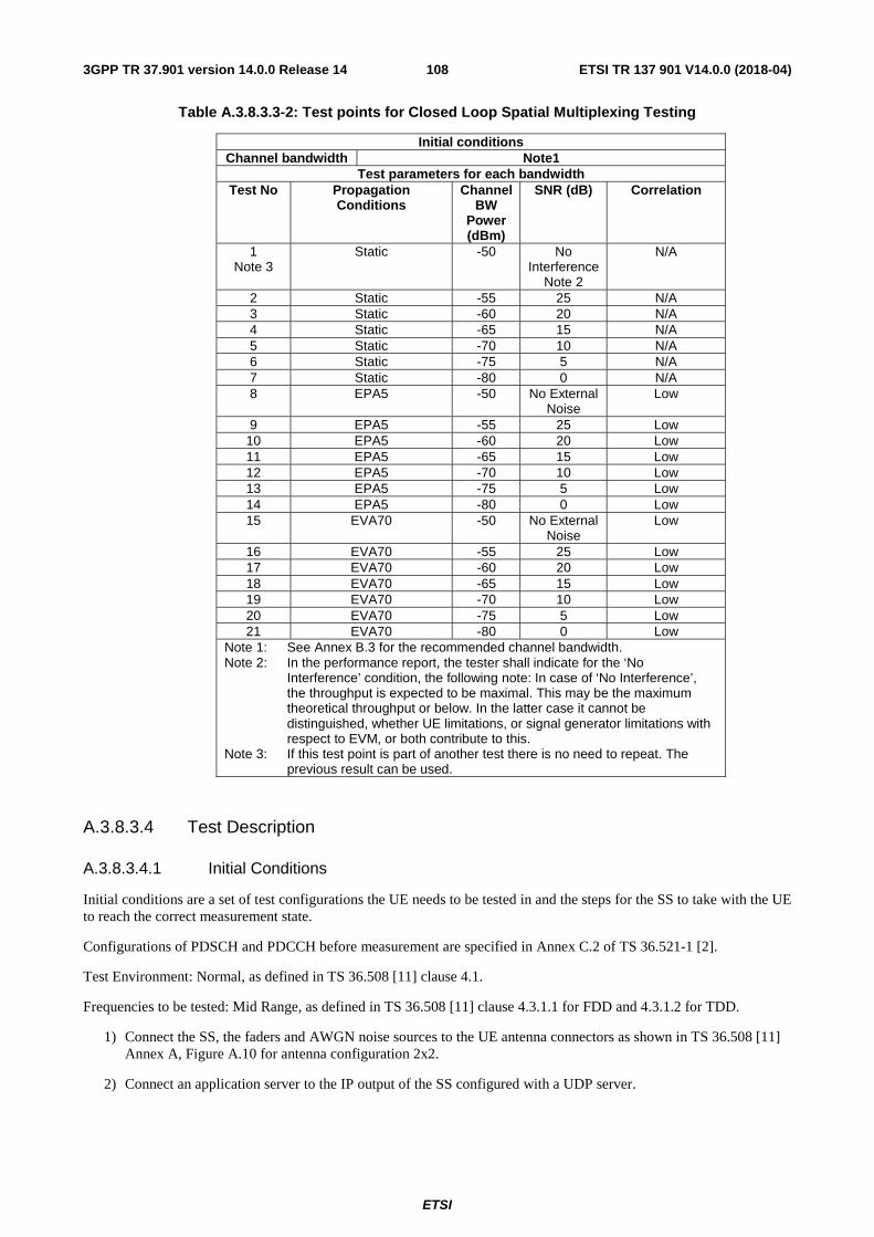
ETSI
ETSI TR 137 901 V14.0.0 (2018-04)1083GPP TR 37.901 version 14.0.0 Release 14
Table A.3.8.3.3-2: Test points for Closed Loop Spatial Multiplexing Testing
Initial conditions Channel bandwidth Note1
Test parameters for each bandwidth Test No Propagation
Conditions Channel
BW Power (dBm)
SNR (dB) Correlation
1 Note 3
Static -50 No Interference
Note 2
N/A
2 Static -55 25 N/A 3 Static -60 20 N/A 4 Static -65 15 N/A 5 Static -70 10 N/A 6 Static -75 5 N/A 7 Static -80 0 N/A 8 EPA5 -50 No External
Noise Low
9 EPA5 -55 25 Low 10 EPA5 -60 20 Low 11 EPA5 -65 15 Low 12 EPA5 -70 10 Low 13 EPA5 -75 5 Low 14 EPA5 -80 0 Low 15 EVA70 -50 No External
Noise Low
16 EVA70 -55 25 Low 17 EVA70 -60 20 Low 18 EVA70 -65 15 Low 19 EVA70 -70 10 Low 20 EVA70 -75 5 Low 21 EVA70 -80 0 Low
Note 1: See Annex B.3 for the recommended channel bandwidth. Note 2: In the performance report, the tester shall indicate for the ‘No
Interference’ condition, the following note: In case of ‘No Interference’, the throughput is expected to be maximal. This may be the maximum theoretical throughput or below. In the latter case it cannot be distinguished, whether UE limitations, or signal generator limitations with respect to EVM, or both contribute to this.
Note 3: If this test point is part of another test there is no need to repeat. The previous result can be used.
A.3.8.3.4 Test Description
A.3.8.3.4.1 Initial Conditions
Initial conditions are a set of test configurations the UE needs to be tested in and the steps for the SS to take with the UE to reach the correct measurement state.
Configurations of PDSCH and PDCCH before measurement are specified in Annex C.2 of TS 36.521-1 [2].
Test Environment: Normal, as defined in TS 36.508 [11] clause 4.1.
Frequencies to be tested: Mid Range, as defined in TS 36.508 [11] clause 4.3.1.1 for FDD and 4.3.1.2 for TDD.
1) Connect the SS, the faders and AWGN noise sources to the UE antenna connectors as shown in TS 36.508 [11] Annex A, Figure A.10 for antenna configuration 2x2.
2) Connect an application server to the IP output of the SS configured with a UDP server.
ETSI
ETSI TR 137 901 V14.0.0 (2018-04)1093GPP TR 37.901 version 14.0.0 Release 14
3) For a tethered configuration, tether the UE to a laptop configured with UDP client software using the appropriate UE to PC interface Modem or Network Interface Connection (NIC) drivers. For an embedded configuration, ensure that the UE has an UDP client test application available.
4) The parameter settings for the cell are set up according to Tables A.3.1-2, A.3.1-3 and A.3.8.3.3-1 as appropriate.
5) Downlink signals are initially set up according to Annex C0, C.1 and Annex C.3.2 in TS 36.521-1 [2] and uplink signals according to Annex H.1 and H.3.2 in TS 36.521-1 [2].
6) Propagation conditions are set according to Annex B.0 in TS 36.521-1 [2].
A.3.8.3.4.2 Procedure
1) SS transmits PDSCH via PDCCH DCI format 2 for C_RNTI to transmit the DL data using the transport format and transport block size determined based on UE reported CQI as described in subclause B.2.2.1. The PMI used by the SS is determined as described in subclause B.2.2.6. The transmission rank used by the SS is determined as described in subclause B.2.2.7.
2) Set the parameters of the bandwidth, reference channel, the propagation condition, the correlation matrix, antenna configuration and the SNR according to Table A.3.8.3.3-2, as appropriate.
3) Using the UDP client, begin UDP download from the application server of a file sufficient in size for the test duration outlined in Table A.3.1-1 and record Throughput T result.
4) Count and record the overall number of ACK and NACK/DTX on the PUSCH/PUCCH during the test interval.
5) Repeat steps 3 and 4 for each subtest in Table A.3.8.3.3-2.
6) If the RRC connection setup needs to be re-established after the subtest, perform the initial call setup in accordance with the initial conditions in clause A.3.8.3.4.1.
7) Record the IP address type (IPv4 or IPv6) used during the file transfers.
A.3.8.4 LTE / UDP Downlink vs. SNR Performance / PDSCH Closed Loop Spatial Multiplexing using a single transmission layer Performance (Cell-Specific Reference Symbols)
A.3.8.4.1 Definition
The UE application layer downlink performance for UDP under different multi-path fading environments is determined by the UE application layer UDP throughput T.
A.3.8.4.2 Test Purpose
To measure the performance of the UE while downloading UDP based data within both static and multi path faded environments.
A.3.8.4.3 Test Parameters
Test parameters are defined in Table A.3.8.4.3-1 and A.3.8.4.3-2.
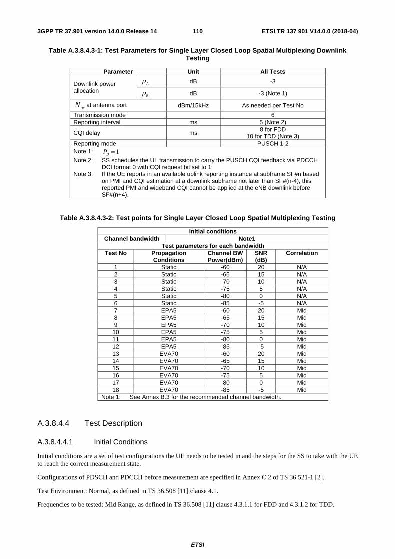
ETSI
ETSI TR 137 901 V14.0.0 (2018-04)1103GPP TR 37.901 version 14.0.0 Release 14
Table A.3.8.4.3-1: Test Parameters for Single Layer Closed Loop Spatial Multiplexing Downlink Testing
Parameter Unit All Tests
Downlink power allocation
dB -3
dB -3 (Note 1)
at antenna port dBm/15kHz As needed per Test No
Transmission mode
6 Reporting interval
ms 5 (Note 2)
CQI delay
ms 8 for FDD 10 for TDD (Note 3)
Reporting mode
PUSCH 1-2 Note 1: Note 2: SS schedules the UL transmission to carry the PUSCH CQI feedback via PDCCH
DCI format 0 with CQI request bit set to 1 Note 3: If the UE reports in an available uplink reporting instance at subframe SF#n based
on PMI and CQI estimation at a downlink subframe not later than SF#(n-4), this reported PMI and wideband CQI cannot be applied at the eNB downlink before SF#(n+4).
Table A.3.8.4.3-2: Test points for Single Layer Closed Loop Spatial Multiplexing Testing
Initial conditions Channel bandwidth Note1
Test parameters for each bandwidth Test No Propagation
Conditions Channel BW Power(dBm)
SNR (dB)
Correlation
1 Static -60 20 N/A 2 Static -65 15 N/A 3 Static -70 10 N/A 4 Static -75 5 N/A 5 Static -80 0 N/A 6 Static -85 -5 N/A 7 EPA5 -60 20 Mid 8 EPA5 -65 15 Mid 9 EPA5 -70 10 Mid
10 EPA5 -75 5 Mid 11 EPA5 -80 0 Mid 12 EPA5 -85 -5 Mid 13 EVA70 -60 20 Mid 14 EVA70 -65 15 Mid 15 EVA70 -70 10 Mid 16 EVA70 -75 5 Mid 17 EVA70 -80 0 Mid 18 EVA70 -85 -5 Mid
Note 1: See Annex B.3 for the recommended channel bandwidth.
A.3.8.4.4 Test Description
A.3.8.4.4.1 Initial Conditions
Initial conditions are a set of test configurations the UE needs to be tested in and the steps for the SS to take with the UE to reach the correct measurement state.
Configurations of PDSCH and PDCCH before measurement are specified in Annex C.2 of TS 36.521-1 [2].
Test Environment: Normal, as defined in TS 36.508 [11] clause 4.1.
Frequencies to be tested: Mid Range, as defined in TS 36.508 [11] clause 4.3.1.1 for FDD and 4.3.1.2 for TDD.
Aρ
Bρ
ocN
1=BP
ETSI
ETSI TR 137 901 V14.0.0 (2018-04)1113GPP TR 37.901 version 14.0.0 Release 14
1) Connect the SS, the faders and AWGN noise sources to the UE antenna connectors as shown in TS 36.508 [11] Annex A, Figure A.10 for antenna configuration 2x2.
2) Connect an application server to the IP output of the SS configured with a UDP server.
3) For a tethered configuration, tether the UE to a laptop configured with UDP client software using the appropriate UE to PC interface Modem or Network Interface Connection (NIC) drivers. For an embedded configuration, ensure that the UE has an UDP client test application available.
4) The parameter settings for the cell are set up according to Tables A.3.1-2, A.3.1-3 and A.3.8.4.3-1 as appropriate.
5) Downlink signals are initially set up according to Annex C0, C.1 and Annex C.3.2 in TS 36.521-1 [2] and uplink signals according to Annex H.1 and H.3.2 in TS 36.521-1 [2].
6) Propagation conditions are set according to Annex B.0 in TS 36.521-1 [2].
A.3.8.4.4.2 Procedure
1) SS transmits PDSCH via PDCCH DCI format 1 for C_RNTI to transmit the DL data using the transport format and transport block size determined based on UE reported CQI as described in subclause B.2.2.1. The PMI used by the SS is determined as described in subclause B.2.2.6.
2) Set the parameters of the bandwidth, reference channel, the propagation condition, the correlation matrix, antenna configuration and the SNR according to Table A.3.8.4.3-2, as appropriate.
3) Using the UDP client, begin UDP download from the application server of a file sufficient in size for the test duration outlined in Table A.3.1-1 and record Throughput T result.
4) Count and record the overall number of ACK and NACK/DTX on the PUSCH/PUCCH during the test interval.
5) Repeat steps 3 and 4 for each subtest in Table A.3.8.4.3-2.
6) If the RRC connection setup needs to be re-established after the subtest, perform the initial call setup in accordance with the initial conditions in clause A.3.8.4.4.1.
7) Record the IP address type (IPv4 or IPv6) used during the file transfers.
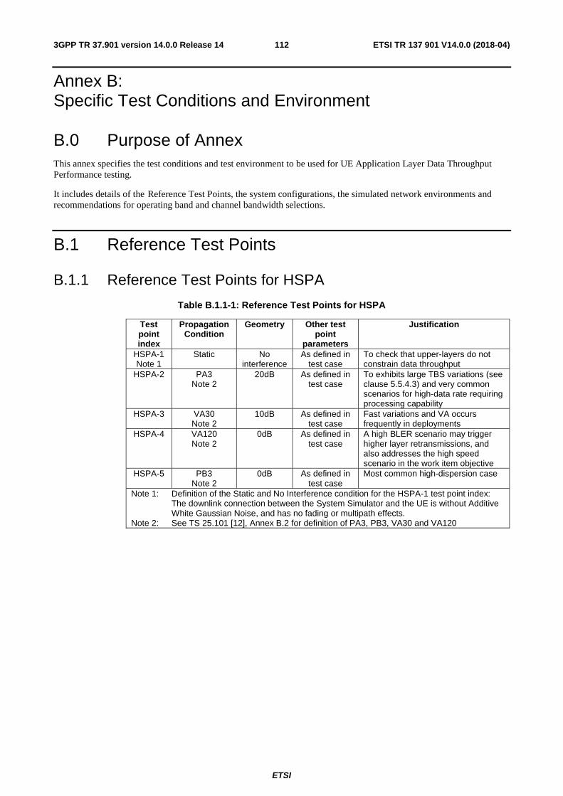
ETSI
ETSI TR 137 901 V14.0.0 (2018-04)1123GPP TR 37.901 version 14.0.0 Release 14
Annex B: Specific Test Conditions and Environment
B.0 Purpose of Annex This annex specifies the test conditions and test environment to be used for UE Application Layer Data Throughput Performance testing.
It includes details of the Reference Test Points, the system configurations, the simulated network environments and recommendations for operating band and channel bandwidth selections.
B.1 Reference Test Points
B.1.1 Reference Test Points for HSPA
Table B.1.1-1: Reference Test Points for HSPA
Test point index
Propagation Condition
Geometry Other test point
parameters
Justification
HSPA-1 Note 1
Static No interference
As defined in test case
To check that upper-layers do not constrain data throughput
HSPA-2 PA3 Note 2
20dB As defined in test case
To exhibits large TBS variations (see clause 5.5.4.3) and very common scenarios for high-data rate requiring processing capability
HSPA-3 VA30 Note 2
10dB As defined in test case
Fast variations and VA occurs frequently in deployments
HSPA-4 VA120 Note 2
0dB As defined in test case
A high BLER scenario may trigger higher layer retransmissions, and also addresses the high speed scenario in the work item objective
HSPA-5 PB3 Note 2
0dB As defined in test case
Most common high-dispersion case
Note 1: Definition of the Static and No Interference condition for the HSPA-1 test point index: The downlink connection between the System Simulator and the UE is without Additive White Gaussian Noise, and has no fading or multipath effects.
Note 2: See TS 25.101 [12], Annex B.2 for definition of PA3, PB3, VA30 and VA120
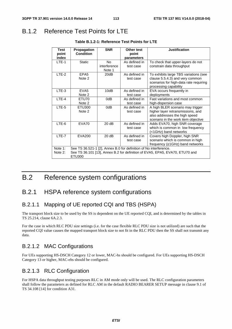
ETSI
ETSI TR 137 901 V14.0.0 (2018-04)1133GPP TR 37.901 version 14.0.0 Release 14
B.1.2 Reference Test Points for LTE
Table B.1.2-1: Reference Test Points for LTE
Test point index
Propagation Condition
SNR Other test point
parameters
Justification
LTE-1 Static No interference
Note 1
As defined in test case
To check that upper-layers do not constrain data throughput
LTE-2 EPA5 Note 2
20dB As defined in test case
To exhibits large TBS variations (see clause 5.5.4.3) and very common scenarios for high-data rate requiring processing capability
LTE-3 EVA5 Note 2
10dB As defined in test case
EVA occurs frequently in deployments
LTE-4 ETU70 Note 2
0dB As defined in test case
Fast variations and most common high-dispersion case
LTE-5 ETU300 Note 2
0dB As defined in test case
A high BLER scenario may trigger higher layer retransmissions, and also addresses the high speed scenario in the work item objective
LTE-6 EVA70 20 dB As defined in test case
Adds EVA70, high SNR coverage which is common in low frequency (<1GHz) band networks
LTE-7 EVA200 20 dB As defined in test case
Covers high Doppler, high SNR scenario which is common in high frequency (≥1GHz) band networks
Note 1: See TS 36.521-1 [2], Annex B.0 for definition of No interference. Note 2: See TS 36.101 [13], Annex B.2 for definition of EVA5, EPA5, EVA70, ETU70 and
ETU300
B.2 Reference system configurations
B.2.1 HSPA reference system configurations
B.2.1.1 Mapping of UE reported CQI and TBS (HSPA)
The transport block size to be used by the SS is dependent on the UE reported CQI, and is determined by the tables in TS 25.214, clause 6A.2.3.
For the case in which RLC PDU size settings (i.e. for the case flexible RLC PDU size is not utilized) are such that the reported CQI value causes the mapped transport block size to not fit in the RLC PDU then the SS shall not transmit any data.
B.2.1.2 MAC Configurations
For UEs supporting HS-DSCH Category 12 or lower, MAC-hs should be configured. For UEs supporting HS-DSCH Category 13 or higher, MAC-ehs should be configured.
B.2.1.3 RLC Configuration
For HSPA data throughput testing purposes RLC in AM mode only will be used. The RLC configuration parameters shall follow the parameters as defined for RLC AM in the default RADIO BEARER SETUP message in clause 9.1 of TS 34.108 [14] for condition A31.
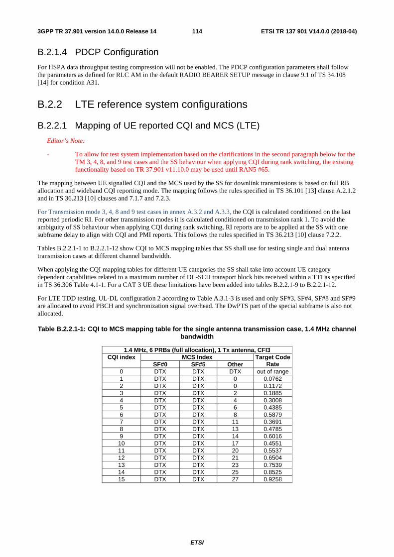
ETSI
ETSI TR 137 901 V14.0.0 (2018-04)1143GPP TR 37.901 version 14.0.0 Release 14
B.2.1.4 PDCP Configuration
For HSPA data throughput testing compression will not be enabled. The PDCP configuration parameters shall follow the parameters as defined for RLC AM in the default RADIO BEARER SETUP message in clause 9.1 of TS 34.108 [14] for condition A31.
B.2.2 LTE reference system configurations
B.2.2.1 Mapping of UE reported CQI and MCS (LTE)
Editor’s Note:
- To allow for test system implementation based on the clarifications in the second paragraph below for the TM 3, 4, 8, and 9 test cases and the SS behaviour when applying CQI during rank switching, the existing functionality based on TR 37.901 v11.10.0 may be used until RAN5 #65.
The mapping between UE signalled CQI and the MCS used by the SS for downlink transmissions is based on full RB allocation and wideband CQI reporting mode. The mapping follows the rules specified in TS 36.101 [13] clause A.2.1.2 and in TS 36.213 [10] clauses and 7.1.7 and 7.2.3.
For Transmission mode 3, 4, 8 and 9 test cases in annex A.3.2 and A.3.3, the CQI is calculated conditioned on the last reported periodic RI. For other transmission modes it is calculated conditioned on transmission rank 1. To avoid the ambiguity of SS behaviour when applying CQI during rank switching, RI reports are to be applied at the SS with one subframe delay to align with CQI and PMI reports. This follows the rules specified in TS 36.213 [10] clause 7.2.2.
Tables B.2.2.1-1 to B.2.2.1-12 show CQI to MCS mapping tables that SS shall use for testing single and dual antenna transmission cases at different channel bandwidth.
When applying the CQI mapping tables for different UE categories the SS shall take into account UE category dependent capabilities related to a maximum number of DL-SCH transport block bits received within a TTI as specified in TS 36.306 Table 4.1-1. For a CAT 3 UE these limitations have been added into tables B.2.2.1-9 to B.2.2.1-12.
For LTE TDD testing, UL-DL configuration 2 according to Table A.3.1-3 is used and only SF#3, SF#4, SF#8 and SF#9 are allocated to avoid PBCH and synchronization signal overhead. The DwPTS part of the special subframe is also not allocated.
Table B.2.2.1-1: CQI to MCS mapping table for the single antenna transmission case, 1.4 MHz channel bandwidth
1.4 MHz, 6 PRBs (full allocation), 1 Tx antenna, CFI3 CQI index MCS Index Target Code
Rate SF#0 SF#5 Other 0 DTX DTX DTX out of range 1 DTX DTX 0 0.0762 2 DTX DTX 0 0.1172 3 DTX DTX 2 0.1885 4 DTX DTX 4 0.3008 5 DTX DTX 6 0.4385 6 DTX DTX 8 0.5879 7 DTX DTX 11 0.3691 8 DTX DTX 13 0.4785 9 DTX DTX 14 0.6016
10 DTX DTX 17 0.4551 11 DTX DTX 20 0.5537 12 DTX DTX 21 0.6504 13 DTX DTX 23 0.7539 14 DTX DTX 25 0.8525 15 DTX DTX 27 0.9258
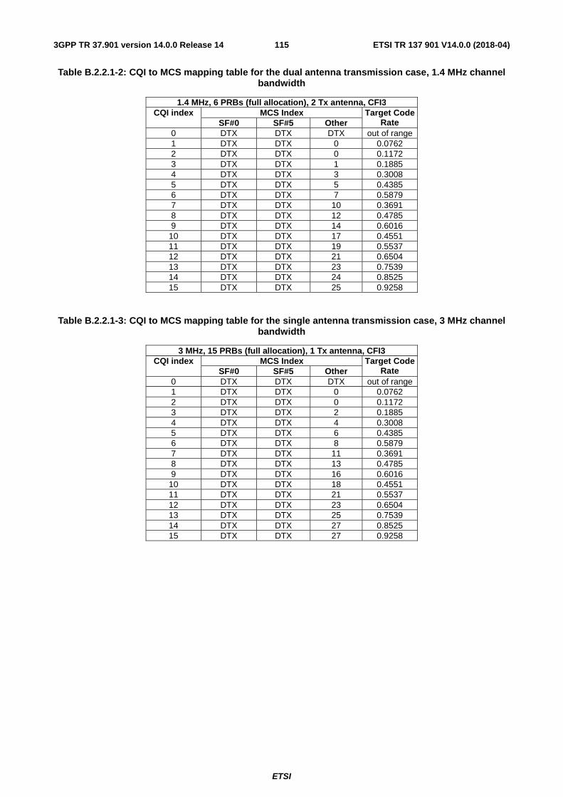
ETSI
ETSI TR 137 901 V14.0.0 (2018-04)1153GPP TR 37.901 version 14.0.0 Release 14
Table B.2.2.1-2: CQI to MCS mapping table for the dual antenna transmission case, 1.4 MHz channel bandwidth
1.4 MHz, 6 PRBs (full allocation), 2 Tx antenna, CFI3 CQI index MCS Index Target Code
Rate SF#0 SF#5 Other 0 DTX DTX DTX out of range 1 DTX DTX 0 0.0762 2 DTX DTX 0 0.1172 3 DTX DTX 1 0.1885 4 DTX DTX 3 0.3008 5 DTX DTX 5 0.4385 6 DTX DTX 7 0.5879 7 DTX DTX 10 0.3691 8 DTX DTX 12 0.4785 9 DTX DTX 14 0.6016
10 DTX DTX 17 0.4551 11 DTX DTX 19 0.5537 12 DTX DTX 21 0.6504 13 DTX DTX 23 0.7539 14 DTX DTX 24 0.8525 15 DTX DTX 25 0.9258
Table B.2.2.1-3: CQI to MCS mapping table for the single antenna transmission case, 3 MHz channel bandwidth
3 MHz, 15 PRBs (full allocation), 1 Tx antenna, CFI3 CQI index MCS Index Target Code
Rate SF#0 SF#5 Other 0 DTX DTX DTX out of range 1 DTX DTX 0 0.0762 2 DTX DTX 0 0.1172 3 DTX DTX 2 0.1885 4 DTX DTX 4 0.3008 5 DTX DTX 6 0.4385 6 DTX DTX 8 0.5879 7 DTX DTX 11 0.3691 8 DTX DTX 13 0.4785 9 DTX DTX 16 0.6016
10 DTX DTX 18 0.4551 11 DTX DTX 21 0.5537 12 DTX DTX 23 0.6504 13 DTX DTX 25 0.7539 14 DTX DTX 27 0.8525 15 DTX DTX 27 0.9258

ETSI
ETSI TR 137 901 V14.0.0 (2018-04)1163GPP TR 37.901 version 14.0.0 Release 14
Table B.2.2.1-4: CQI to MCS mapping table for the dual antenna transmission case, 3 MHz channel bandwidth
3 MHz, 15 PRBs (full allocation), 2 Tx antenna, CFI3 CQI index MCS Index Target Code
Rate SF#0 SF#5 Other 0 DTX DTX DTX out of range 1 DTX DTX 0 0.0762 2 DTX DTX 0 0.1172 3 DTX DTX 2 0.1885 4 DTX DTX 4 0.3008 5 DTX DTX 6 0.4385 6 DTX DTX 8 0.5879 7 DTX DTX 11 0.3691 8 DTX DTX 13 0.4785 9 DTX DTX 15 0.6016
10 DTX DTX 18 0.4551 11 DTX DTX 20 0.5537 12 DTX DTX 22 0.6504 13 DTX DTX 24 0.7539 14 DTX DTX 26 0.8525 15 DTX DTX 27 0.9258
Table B.2.2.1-5: CQI to MCS mapping table for the single antenna transmission case, 5 MHz channel bandwidth
5 MHz, 25 PRBs (full allocation), 1 Tx antenna, CFI3 CQI index MCS Index Target Code
Rate SF#0 SF#5 Other 0 DTX DTX DTX out of range 1 DTX DTX 0 0.0762 2 DTX DTX 0 0.1172 3 DTX DTX 2 0.1885 4 DTX DTX 4 0.3008 5 DTX DTX 6 0.4385 6 DTX DTX 8 0.5879 7 DTX DTX 11 0.3691 8 DTX DTX 13 0.4785 9 DTX DTX 16 0.6016
10 DTX DTX 19 0.4551 11 DTX DTX 21 0.5537 12 DTX DTX 23 0.6504 13 DTX DTX 25 0.7539 14 DTX DTX 27 0.8525 15 DTX DTX 27 0.9258
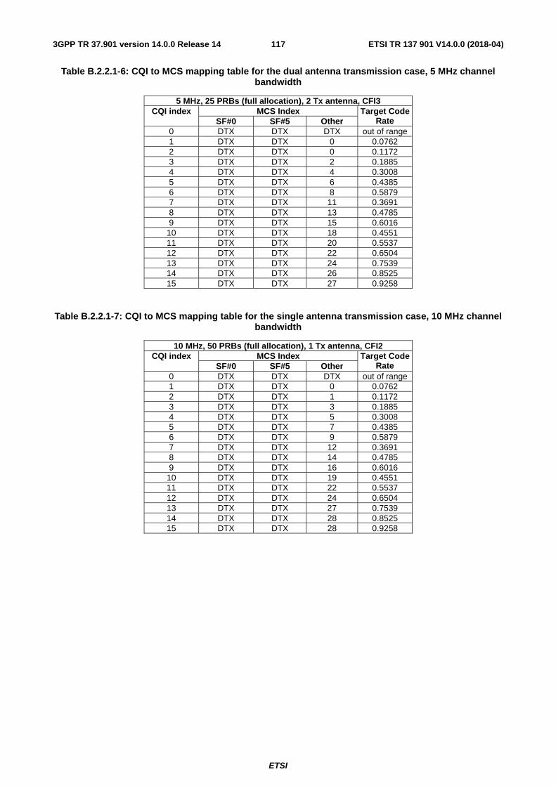
ETSI
ETSI TR 137 901 V14.0.0 (2018-04)1173GPP TR 37.901 version 14.0.0 Release 14
Table B.2.2.1-6: CQI to MCS mapping table for the dual antenna transmission case, 5 MHz channel bandwidth
5 MHz, 25 PRBs (full allocation), 2 Tx antenna, CFI3 CQI index MCS Index Target Code
Rate SF#0 SF#5 Other 0 DTX DTX DTX out of range 1 DTX DTX 0 0.0762 2 DTX DTX 0 0.1172 3 DTX DTX 2 0.1885 4 DTX DTX 4 0.3008 5 DTX DTX 6 0.4385 6 DTX DTX 8 0.5879 7 DTX DTX 11 0.3691 8 DTX DTX 13 0.4785 9 DTX DTX 15 0.6016
10 DTX DTX 18 0.4551 11 DTX DTX 20 0.5537 12 DTX DTX 22 0.6504 13 DTX DTX 24 0.7539 14 DTX DTX 26 0.8525 15 DTX DTX 27 0.9258
Table B.2.2.1-7: CQI to MCS mapping table for the single antenna transmission case, 10 MHz channel bandwidth
10 MHz, 50 PRBs (full allocation), 1 Tx antenna, CFI2 CQI index MCS Index Target Code
Rate SF#0 SF#5 Other 0 DTX DTX DTX out of range 1 DTX DTX 0 0.0762 2 DTX DTX 1 0.1172 3 DTX DTX 3 0.1885 4 DTX DTX 5 0.3008 5 DTX DTX 7 0.4385 6 DTX DTX 9 0.5879 7 DTX DTX 12 0.3691 8 DTX DTX 14 0.4785 9 DTX DTX 16 0.6016
10 DTX DTX 19 0.4551 11 DTX DTX 22 0.5537 12 DTX DTX 24 0.6504 13 DTX DTX 27 0.7539 14 DTX DTX 28 0.8525 15 DTX DTX 28 0.9258
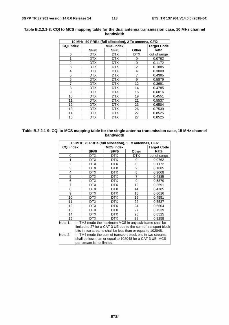
ETSI
ETSI TR 137 901 V14.0.0 (2018-04)1183GPP TR 37.901 version 14.0.0 Release 14
Table B.2.2.1-8: CQI to MCS mapping table for the dual antenna transmission case, 10 MHz channel bandwidth
10 MHz, 50 PRBs (full allocation), 2 Tx antenna, CFI2 CQI index MCS Index Target Code
Rate SF#0 SF#5 Other 0 DTX DTX DTX out of range 1 DTX DTX 0 0.0762 2 DTX DTX 0 0.1172 3 DTX DTX 2 0.1885 4 DTX DTX 4 0.3008 5 DTX DTX 7 0.4385 6 DTX DTX 9 0.5879 7 DTX DTX 12 0.3691 8 DTX DTX 14 0.4785 9 DTX DTX 16 0.6016
10 DTX DTX 19 0.4551 11 DTX DTX 21 0.5537 12 DTX DTX 23 0.6504 13 DTX DTX 26 0.7539 14 DTX DTX 27 0.8525 15 DTX DTX 27 0.8525
Table B.2.2.1-9: CQI to MCS mapping table for the single antenna transmission case, 15 MHz channel bandwidth
15 MHz, 75 PRBs (full allocation), 1 Tx antennas, CFI2 CQI index MCS Index Target Code
Rate SF#0 SF#5 Other 0 DTX DTX DTX out of range 1 DTX DTX 0 0.0762 2 DTX DTX 0 0.1172 3 DTX DTX 2 0.1885 4 DTX DTX 5 0.3008 5 DTX DTX 7 0.4385 6 DTX DTX 9 0.5879 7 DTX DTX 12 0.3691 8 DTX DTX 14 0.4785 9 DTX DTX 16 0.6016 10 DTX DTX 19 0.4551 11 DTX DTX 22 0.5537 12 DTX DTX 24 0.6504 13 DTX DTX 27 0.7539 14 DTX DTX 28 0.8525 15 DTX DTX 28 0.9258
Note 1: In TM3 mode the maximum MCS in any sub-frame shall be limited to 27 for a CAT 3 UE due to the sum of transport block bits in two streams shall be less than or equal to 102048.
Note 2: In TM4 mode the sum of transport block bits in two streams shall be less than or equal to 102048 for a CAT 3 UE. MCS per stream is not limited.
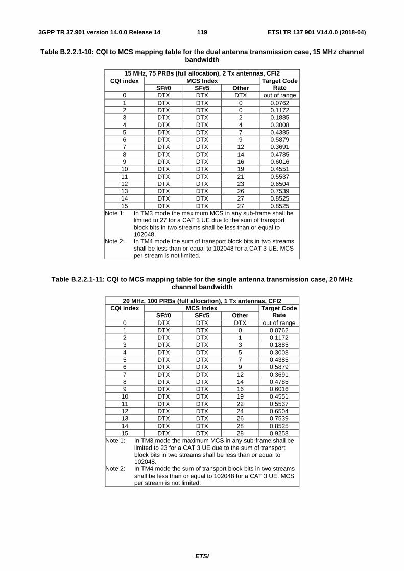
ETSI
ETSI TR 137 901 V14.0.0 (2018-04)1193GPP TR 37.901 version 14.0.0 Release 14
Table B.2.2.1-10: CQI to MCS mapping table for the dual antenna transmission case, 15 MHz channel bandwidth
15 MHz, 75 PRBs (full allocation), 2 Tx antennas, CFI2 CQI index MCS Index Target Code
Rate SF#0 SF#5 Other 0 DTX DTX DTX out of range 1 DTX DTX 0 0.0762 2 DTX DTX 0 0.1172 3 DTX DTX 2 0.1885 4 DTX DTX 4 0.3008 5 DTX DTX 7 0.4385 6 DTX DTX 9 0.5879 7 DTX DTX 12 0.3691 8 DTX DTX 14 0.4785 9 DTX DTX 16 0.6016
10 DTX DTX 19 0.4551 11 DTX DTX 21 0.5537 12 DTX DTX 23 0.6504 13 DTX DTX 26 0.7539 14 DTX DTX 27 0.8525 15 DTX DTX 27 0.8525
Note 1: In TM3 mode the maximum MCS in any sub-frame shall be limited to 27 for a CAT 3 UE due to the sum of transport block bits in two streams shall be less than or equal to 102048.
Note 2: In TM4 mode the sum of transport block bits in two streams shall be less than or equal to 102048 for a CAT 3 UE. MCS per stream is not limited.
Table B.2.2.1-11: CQI to MCS mapping table for the single antenna transmission case, 20 MHz channel bandwidth
20 MHz, 100 PRBs (full allocation), 1 Tx antennas, CFI2 CQI index MCS Index Target Code
Rate SF#0 SF#5 Other 0 DTX DTX DTX out of range 1 DTX DTX 0 0.0762 2 DTX DTX 1 0.1172 3 DTX DTX 3 0.1885 4 DTX DTX 5 0.3008 5 DTX DTX 7 0.4385 6 DTX DTX 9 0.5879 7 DTX DTX 12 0.3691 8 DTX DTX 14 0.4785 9 DTX DTX 16 0.6016 10 DTX DTX 19 0.4551 11 DTX DTX 22 0.5537 12 DTX DTX 24 0.6504 13 DTX DTX 26 0.7539 14 DTX DTX 28 0.8525 15 DTX DTX 28 0.9258
Note 1: In TM3 mode the maximum MCS in any sub-frame shall be limited to 23 for a CAT 3 UE due to the sum of transport block bits in two streams shall be less than or equal to 102048.
Note 2: In TM4 mode the sum of transport block bits in two streams shall be less than or equal to 102048 for a CAT 3 UE. MCS per stream is not limited.
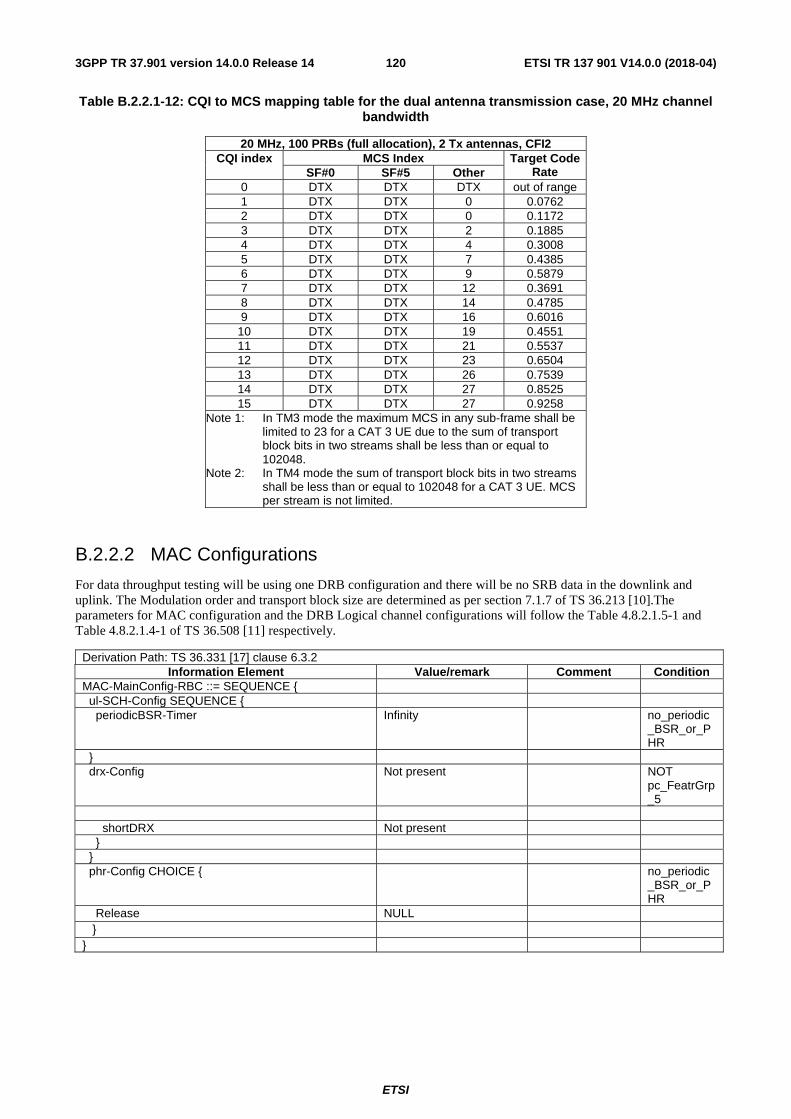
ETSI
ETSI TR 137 901 V14.0.0 (2018-04)1203GPP TR 37.901 version 14.0.0 Release 14
Table B.2.2.1-12: CQI to MCS mapping table for the dual antenna transmission case, 20 MHz channel bandwidth
20 MHz, 100 PRBs (full allocation), 2 Tx antennas, CFI2 CQI index MCS Index Target Code
Rate SF#0 SF#5 Other 0 DTX DTX DTX out of range 1 DTX DTX 0 0.0762 2 DTX DTX 0 0.1172 3 DTX DTX 2 0.1885 4 DTX DTX 4 0.3008 5 DTX DTX 7 0.4385 6 DTX DTX 9 0.5879 7 DTX DTX 12 0.3691 8 DTX DTX 14 0.4785 9 DTX DTX 16 0.6016
10 DTX DTX 19 0.4551 11 DTX DTX 21 0.5537 12 DTX DTX 23 0.6504 13 DTX DTX 26 0.7539 14 DTX DTX 27 0.8525 15 DTX DTX 27 0.9258
Note 1: In TM3 mode the maximum MCS in any sub-frame shall be limited to 23 for a CAT 3 UE due to the sum of transport block bits in two streams shall be less than or equal to 102048.
Note 2: In TM4 mode the sum of transport block bits in two streams shall be less than or equal to 102048 for a CAT 3 UE. MCS per stream is not limited.
B.2.2.2 MAC Configurations
For data throughput testing will be using one DRB configuration and there will be no SRB data in the downlink and uplink. The Modulation order and transport block size are determined as per section 7.1.7 of TS 36.213 [10].The parameters for MAC configuration and the DRB Logical channel configurations will follow the Table 4.8.2.1.5-1 and Table 4.8.2.1.4-1 of TS 36.508 [11] respectively.
Derivation Path: TS 36.331 [17] clause 6.3.2 Information Element Value/remark Comment Condition
MAC-MainConfig-RBC ::= SEQUENCE { ul-SCH-Config SEQUENCE { periodicBSR-Timer Infinity no_periodic
_BSR_or_PHR
} drx-Config Not present NOT
pc_FeatrGrp_5
shortDRX Not present } } phr-Config CHOICE { no_periodic
_BSR_or_PHR
Release NULL } }
ETSI
ETSI TR 137 901 V14.0.0 (2018-04)1213GPP TR 37.901 version 14.0.0 Release 14
B.2.2.3 RLC Configuration
For LTE data throughput testing purposes RLC in AM mode only will be used. The RLC configuration parameters shall follow Table 4.8.2.1.3.2-1 of TS 36.508 [11].
B.2.2.4 PDCP Configuration
For LTE data throughput testing compression will not be enabled. PDCP configuration for DRB in RLC AM mode shall follow Table 4.8.2.1.2.2-1 of TS 36.508 [11].
B.2.2.5 System Information
Maximum channel bandwidth shall be considered for testing. Hence dl-Bandwidth will be set to downlink system bandwidth under test. The SIB periodicity is mentioned in table 4.4.3.4-1 for bandwidth under test. Other system information IE’s are used as per TS 36.508 [11] section 4.4.3.2.
B.2.2.6 Mapping of UE reported PMI
The PMI to be used by the SS is determined by the following procedure:
The SS shall transmit PDSCH with selected precoding matrix from codebook (Table 6.3.4.2.3-1 in TS 36.211 [8]) every subframe according to PMI reports from the UE. In case of multiple PMI reporting the precoding matrix corresponding to the PMI reported by the UE is applied on the respective sub band.
B.2.2.7 Mapping of UE reported RI
In Transmission Modes 3 and 4 the SS shall follow UE RI reports and apply reported rank even when retransmissions are required.
The following guidelines are provided to clarify the operation in regard to retransmissions based on the proposal above. This guidance is based on the 2 downlink antenna ports case. In the following RI change means a change of the UE RI reported value between initial transmission / first retransmission or retransmission / next retransmission of a codeword.
a. If RI =1 and does not change, rank = 1 transmission consists of retransmitting one codeword.
b. If RI = 2 and does not change, it depends on how many codewords need to be retransmitted:
- If both codewords need to be retransmitted, rank = 2 transmission consists of retransmitting both codewords.
- If only one codeword needs to be retransmitted, rank = 2 transmission consists of retransmitting one codeword + transmitting another new codeword.
c. If RI changes from 1 to 2, rank = 2 transmission consists of retransmitting one codeword + transmitting another new codeword.
d. If RI changes from 2 to 1, it depends on how many codewords need to be retransmitted:
- If both codewords need to be retransmitted, rank =1 transmission consists of retransmitting each of the codewords alternately in different TTI-s.
- If only one codeword needs to be retransmitted, rank =1 transmission consists of retransmitting one codeword.
B.2.3 Network, Transport and Application Layers reference system configurations
B.2.3.1 FTP Reference System Configuration
The FTP server should be configured to meet the following requirements:
ETSI
ETSI TR 137 901 V14.0.0 (2018-04)1223GPP TR 37.901 version 14.0.0 Release 14
- The TCP send/receive buffer sizes at the FTP server should be set to values sufficiently large to ensure they do not limit the maximum throughput achievable at the UE
- The tx queue length should be set to a value sufficiently large value to ensure flow control between the network interface (ppp) and TCP is not triggered
The FTP application used on the tethered PC for tethered testing should meet the following requirements:
- The tethered FTP application should allow the user to transfer files of any format supported by the tethered PC, in binary mode, in both the Downlink and the Uplink
- The tethered FTP application should provide the means to compute the throughput T as defined in subclause 5.1.2 at the end of each file transfer
- The tethered FTP application should provide an interface allowing automation of testing
- The tethered FTP application t should not implement hidden optimizations that might impact the throughput
For embedded testing, the FTP client will reside in the UE under test. This will require an FTP application to be installed on the UE. The FTP application used for embedded testing should meet the following requirements:
- The embedded FTP application should allow the user to transfer files of formats supported by the UE, in binary mode, both in the Downlink and the Uplink.
- The embedded FTP application should provide the means to compute the throughput T as defined in subclause 5.1.2 at the end of each file transfer.
- The embedded FTP application should provide an interface allowing automation of testing. If an interface for automation of testing is implemented, it is recommended to use the embedded data client automation recommendations in Annex E.
- The embedded FTP application should not implement hidden optimizations that might impact the throughput.
At both the FTP client and the FTP server, the following settings should be used:
- The TCPWindowSize is set to a value greater than the BDP (bandwidth-delay product), with BDP computed as (max TCP data rate * RTT upper bound). Refer to clause 5.4.2.1.1 for guidance concerning the TCP advertised receiver window size setting.
- The TCPWindowSize is adjusted to near even-multiple of TCP MTU. The Windows Scaling is enabled for all FTP transfers.
- The socket buffer sizes are set to even-multiples of TCP MTU in use and set to values close to the BDP.
- The TCP MTU size is set to a value comprised between 1280 and 1500 bytes as recommended by the manufacturer.
- The FTP transfers are always carried out in Binary mode.
- The contents of the files to be transferred over FTP are chosen in such a way that they are statistically random, with least compressibility.
- No application level compression protocols are used to compress the FTP files.
- Either IPv4 or IPv6 can be used, but only results obtained with the same IP address type can be compared, since the IP address type will affect the measured throughput.
B.2.3.2 UDP Reference System Configuration
The UDP server should be configured to meet the following requirements:
- UDP blast duration shall be selected to meet the minimum test times using a sufficient rate to prevent physical layer DTX based upon the UE Category.
The UDP application used on the tethered PC for tethered testing should meet the following requirements:
ETSI
ETSI TR 137 901 V14.0.0 (2018-04)1233GPP TR 37.901 version 14.0.0 Release 14
- The tethered UDP application should allow the user to transfer files of any format supported by the tethered PC, in binary mode, in both the Downlink and the Uplink.
- The tethered UDP application should provide the means to compute the throughput T as defined in subclause 5.1.2.
- The tethered UDP application should provide an interface allowing automation of testing.
- The tethered UDP application should not implement hidden optimizations that might impact the throughput.
For embedded testing, the UDP client will reside in the UE under test. This will require an UDP application to be installed on the UE. The UDP application used for embedded testing should meet the following requirements:
- The embedded UDP application should allow the user to transfer files of formats supported by the UE, in binary mode, both in the Downlink and the Uplink.
- The embedded UDP application should provide the means to compute the throughput T as defined in subclause 5.1.2.
- The embedded UDP application should provide an interface allowing automation of testing. If an interface for automation of testing is implemented, it is recommended to use the embedded data client automation recommendations in Annex E.
- The embedded UDP application should not implement hidden optimizations that might impact the throughput.
The following settings are to be used.
- The UDP MTU size is set to a value comprised between 1280 and 1500 bytes as recommended by the manufacturer.
- The UDP transfers are always carried out in Binary mode.
- The contents of the files to be transferred over UDP are chosen in such a way that they are statistically random, with least compressibility.
- No application level compression protocols are used to compress the UDP files.
- It is recommended that no control characters be used in the files as this may cause unexpected behaviour.
- Either IPv4 or IPv6 can be used, but only results obtained with the same IP address type can be compared, since the IP address type will affect the measured throughput.
B.3 Recommendation for Operating band and Channel Bandwidth selection for application layer data throughput measurements
The UE application layer data throughput measurements as described in this TR is considered to be operating band independent unless specified in a particular test point. Therefore, unless noted in the test point the application layer data throughput measurement can be verified in one of the operating bands supported by the UE under test for HSPA and LTE respectively.
For LTE it is recommended that the measurements are performed using the maximum channel bandwidth
NOTE: For HSPA and LTE the measurement procedures as specified in Annex A of this TR are transparent to which operating band is used for the measurements. For LTE the measurement procedures as specified in Annex A of this TR are transparent to which channel bandwidth is used for the measurements.
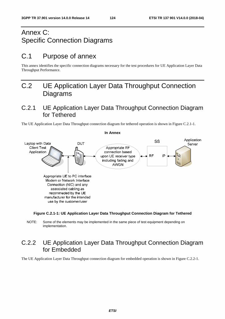
ETSI
ETSI TR 137 901 V14.0.0 (2018-04)1243GPP TR 37.901 version 14.0.0 Release 14
Annex C: Specific Connection Diagrams
C.1 Purpose of annex This annex identifies the specific connection diagrams necessary for the test procedures for UE Application Layer Data Throughput Performance.
C.2 UE Application Layer Data Throughput Connection Diagrams
C.2.1 UE Application Layer Data Throughput Connection Diagram for Tethered
The UE Application Layer Data Throughput connection diagram for tethered operation is shown in Figure C.2.1-1.
In Annex
Figure C.2.1-1: UE Application Layer Data Throughput Connection Diagram for Tethered
NOTE: Some of the elements may be implemented in the same piece of test equipment depending on implementation.
C.2.2 UE Application Layer Data Throughput Connection Diagram for Embedded
The UE Application Layer Data Throughput connection diagram for embedded operation is shown in Figure C.2.2-1.
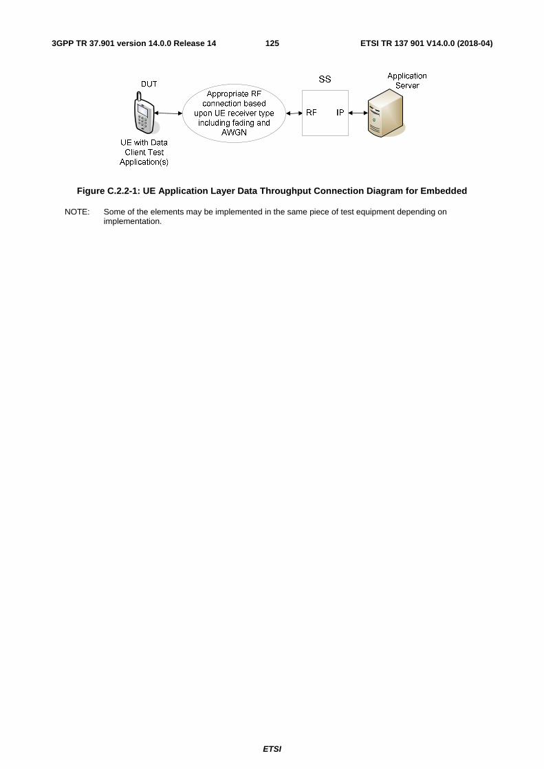
ETSI
ETSI TR 137 901 V14.0.0 (2018-04)1253GPP TR 37.901 version 14.0.0 Release 14
Figure C.2.2-1: UE Application Layer Data Throughput Connection Diagram for Embedded
NOTE: Some of the elements may be implemented in the same piece of test equipment depending on implementation.
ETSI
ETSI TR 137 901 V14.0.0 (2018-04)1263GPP TR 37.901 version 14.0.0 Release 14
Annex D: Applicability
D.1 Purpose of annex The present annex specifies a recommended applicability statement for the test cases included in Annex A. These applicability statements are based on the features implemented in the UE for the indication of which an Implementation Conformance Statement (ICS) proforma is also provided.
D.2 Recommended Test Case Applicability The applicability of each individual test is identified in Table D.2-1. This is just a recommendation based on the purpose for which the test case was written.
The applicability of every test is formally expressed by the use of Boolean expression that are based on parameters (ICS) included in suction D.3 of the present document.
Additional information related to the Test Case (TC), e.g. affecting its dynamic behaviour or its execution may be provided as well.
The columns in Table D.2-1 have the following meaning:
Clause
The clause column indicates the clause number in Annex A that contains the test body.
Title
The title column describes the name of the test and contains the clause title of the clause in Annex A that contains the test body.
Release
The release column indicates the earliest release from which each the test case is applicable.
Applicability - Condition
The following notations are used for the applicability column:
R recommended - the test case is recommended
O optional – the test case is optional
N/A not applicable - in the given context, the test case is not recommended.
Ci conditional - the test is recommended ("R") or not ("N/A") depending on the support of other items. "i" is an integer identifying an unique conditional status expression which is defined immediately following the table. For nested conditional expressions, the syntax "IF ... THEN (IF ... THEN ... ELSE...) ELSE ..." is used to avoid ambiguities.
NOTE: The conditions are defined in Table D.2-1a.
Applicability - Comments
This column contains a verbal description of the condition.
Additional Information - Specific ICS
This column contains the mnemonics of ICS(s) affecting the dynamic behaviour of the TC.

ETSI
ETSI TR 137 901 V14.0.0 (2018-04)1273GPP TR 37.901 version 14.0.0 Release 14
Additional Information - Specific IXIT
This column contains the mnemonics of IXIT(s) affecting the dynamic behaviour of the TC.
Additional Information - Number of TC Executions
This column contains, wherever applicable, the recommended for performance data throughput capability number of TC executions. Clarifying notes are listed in Table D.2-1b.
ETSI
ETSI TR 137 901 V14.0.0 (2018-04)1283GPP TR 37.901 version 14.0.0 Release 14
Table D.2-1: Applicability of tests and additional information for testing
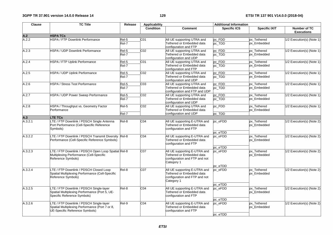
ETSI
ETSI TR 137 901 V14.0.0 (2018-04)1293GPP TR 37.901 version 14.0.0 Release 14
Clause TC Title Release Applicability Additional Information Condition Comment Specific ICS Specific IXIT Number of TC
Executions A.2 HSPA TCs A.2.2 HSPA / FTP Downlink Performance Rel-5 C01 All UE supporting UTRA and
Tethered or Embedded data configuration and FTP
pc_FDD px_Tethered px_Embedded
1/2 Execution(s) (Note 1) Rel-7 pc_TDD
A.2.3 HSPA / UDP Downlink Performance Rel-5 C02 All UE supporting UTRA and Tethered or Embedded data configuration and UDP
pc_FDD px_Tethered px_Embedded
1/2 Execution(s) (Note 1) Rel-7 pc_TDD
A.2.4 HSPA / FTP Uplink Performance Rel-5 C01 All UE supporting UTRA and Tethered or Embedded data configuration and FTP
pc_FDD px_Tethered px_Embedded
1/2 Execution(s) (Note 1) Rel-7 pc_TDD
A.2.5 HSPA / UDP Uplink Performance Rel-5 C02 All UE supporting UTRA and Tethered or Embedded data configuration and UDP
pc_FDD px_Tethered px_Embedded
1/2 Execution(s) (Note 1) Rel-7 pc_TDD
A.2.6 HSPA / Stress Test Performance Rel-5 C03 All UE supporting UTRA and Tethered or Embedded data configuration and FTP and UDP
pc_FDD px_Tethered px_Embedded
1/2 Execution(s) (Note 1) Rel-7 pc_TDD
A.2.7 HSPA / UDP Power Sweep Performance Rel-5 C02 All UE supporting UTRA and Tethered or Embedded data configuration and UDP
pc_FDD px_Tethered px_Embedded
1/2 Execution(s) (Note 1) Rel-7 pc_TDD
A.2.8 HSPA / Throughput vs. Geometry Factor Performance
Rel-5 C02 All UE supporting UTRA and Tethered or Embedded data configuration and UDP
pc_FDD px_Tethered px_Embedded
1/2 Execution(s) (Note 1)
Rel-7 pc_TDD A.3 LTE TCs A.3.2.1 LTE / FTP Downlink / PDSCH Single Antenna
Port Performance (Cell-Specific Reference Symbols)
Rel-8 C04 All UE supporting E-UTRA and Tethered or Embedded data configuration and FTP
pc_eFDD px_Tethered px_Embedded
1/2 Execution(s) (Note 2)
pc_eTDD A.3.2.2 LTE / FTP Downlink / PDSCH Transmit Diversity
Performance (Cell-Specific Reference Symbols) Rel-8 C04 All UE supporting E-UTRA and
Tethered or Embedded data configuration and FTP
pc_eFDD px_Tethered px_Embedded
1/2 Execution(s) (Note 2)
pc_eTDD A.3.2.3 LTE / FTP Downlink / PDSCH Open Loop Spatial
Multiplexing Performance (Cell-Specific Reference Symbols)
Rel-8 C07 All UE supporting E-UTRA and Tethered or Embedded data configuration and FTP and not Category 1
pc_eFDD px_Tethered px_Embedded
1/2 Execution(s) (Note 2)
pc_eTDD A.3.2.4 LTE / FTP Downlink / PDSCH Closed Loop
Spatial Multiplexing Performance (Cell-Specific Reference Symbols)
Rel-8 C07 All UE supporting E-UTRA and Tethered or Embedded data configuration and FTP and not Category 1
pc_eFDD px_Tethered px_Embedded
1/2 Execution(s) (Note 2)
pc_eTDD A.3.2.5 LTE / FTP Downlink / PDSCH Single-layer
Spatial Multiplexing Performance (Port 5, UE-Specific Reference Symbols)
Rel-8 C04 All UE supporting E-UTRA and Tethered or Embedded data configuration and FTP
pc_eFDD px_Tethered px_Embedded
1/2 Execution(s) (Note 2)
pc_eTDD A.3.2.6 LTE / FTP Downlink / PDSCH Single-layer
Spatial Multiplexing Performance (Port 7 or 8, UE-Specific Reference Symbols)
Rel-9 C04 All UE supporting E-UTRA and Tethered or Embedded data configuration and FTP
pc_eFDD px_Tethered px_Embedded
1/2 Execution(s) (Note 2)
pc_eTDD
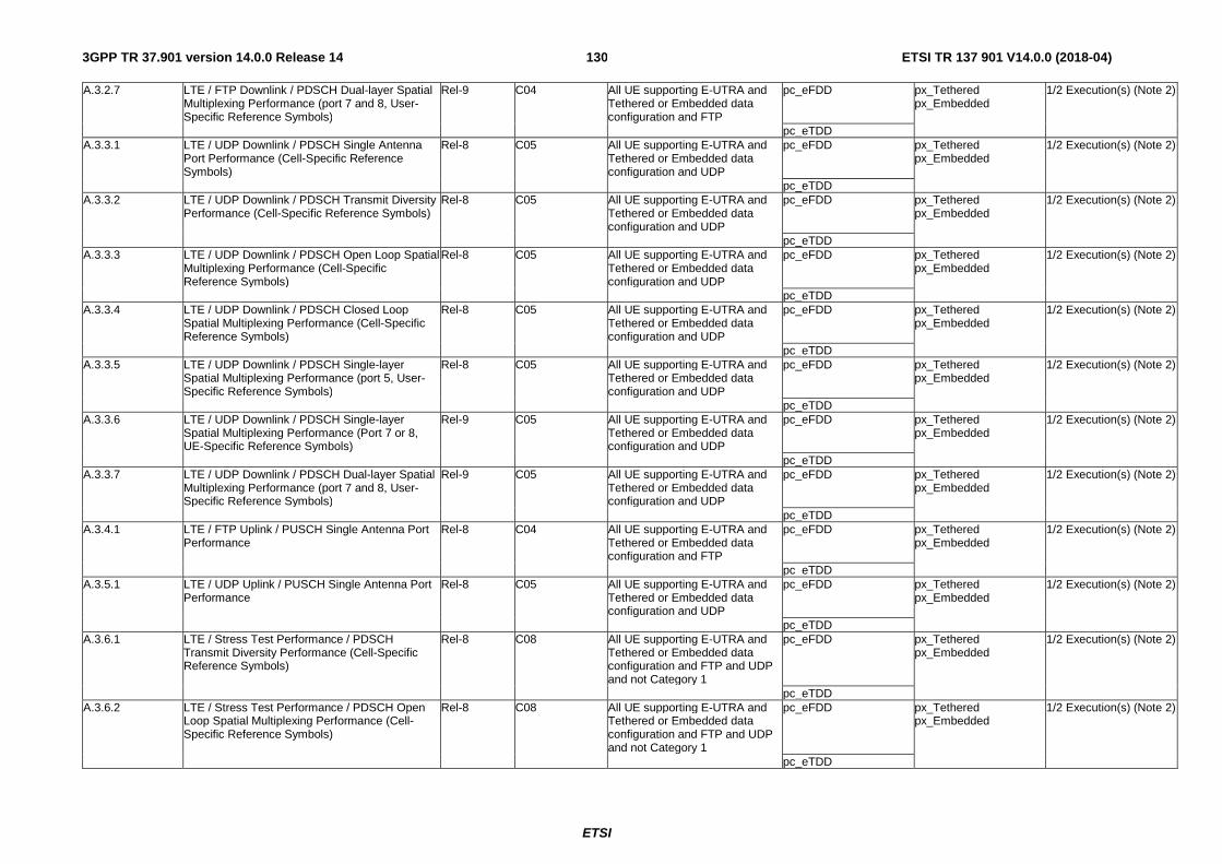
ETSI
ETSI TR 137 901 V14.0.0 (2018-04)1303GPP TR 37.901 version 14.0.0 Release 14
A.3.2.7 LTE / FTP Downlink / PDSCH Dual-layer Spatial Multiplexing Performance (port 7 and 8, User-Specific Reference Symbols)
Rel-9 C04 All UE supporting E-UTRA and Tethered or Embedded data configuration and FTP
pc_eFDD px_Tethered px_Embedded
1/2 Execution(s) (Note 2)
pc_eTDD A.3.3.1 LTE / UDP Downlink / PDSCH Single Antenna
Port Performance (Cell-Specific Reference Symbols)
Rel-8 C05 All UE supporting E-UTRA and Tethered or Embedded data configuration and UDP
pc_eFDD px_Tethered px_Embedded
1/2 Execution(s) (Note 2)
pc_eTDD A.3.3.2 LTE / UDP Downlink / PDSCH Transmit Diversity
Performance (Cell-Specific Reference Symbols) Rel-8 C05 All UE supporting E-UTRA and
Tethered or Embedded data configuration and UDP
pc_eFDD px_Tethered px_Embedded
1/2 Execution(s) (Note 2)
pc_eTDD A.3.3.3 LTE / UDP Downlink / PDSCH Open Loop Spatial
Multiplexing Performance (Cell-Specific Reference Symbols)
Rel-8 C05 All UE supporting E-UTRA and Tethered or Embedded data configuration and UDP
pc_eFDD px_Tethered px_Embedded
1/2 Execution(s) (Note 2)
pc_eTDD A.3.3.4 LTE / UDP Downlink / PDSCH Closed Loop
Spatial Multiplexing Performance (Cell-Specific Reference Symbols)
Rel-8 C05 All UE supporting E-UTRA and Tethered or Embedded data configuration and UDP
pc_eFDD px_Tethered px_Embedded
1/2 Execution(s) (Note 2)
pc_eTDD A.3.3.5 LTE / UDP Downlink / PDSCH Single-layer
Spatial Multiplexing Performance (port 5, User-Specific Reference Symbols)
Rel-8 C05 All UE supporting E-UTRA and Tethered or Embedded data configuration and UDP
pc_eFDD px_Tethered px_Embedded
1/2 Execution(s) (Note 2)
pc_eTDD A.3.3.6 LTE / UDP Downlink / PDSCH Single-layer
Spatial Multiplexing Performance (Port 7 or 8, UE-Specific Reference Symbols)
Rel-9 C05 All UE supporting E-UTRA and Tethered or Embedded data configuration and UDP
pc_eFDD px_Tethered px_Embedded
1/2 Execution(s) (Note 2)
pc_eTDD A.3.3.7 LTE / UDP Downlink / PDSCH Dual-layer Spatial
Multiplexing Performance (port 7 and 8, User-Specific Reference Symbols)
Rel-9 C05 All UE supporting E-UTRA and Tethered or Embedded data configuration and UDP
pc_eFDD px_Tethered px_Embedded
1/2 Execution(s) (Note 2)
pc_eTDD A.3.4.1 LTE / FTP Uplink / PUSCH Single Antenna Port
Performance Rel-8 C04 All UE supporting E-UTRA and
Tethered or Embedded data configuration and FTP
pc_eFDD px_Tethered px_Embedded
1/2 Execution(s) (Note 2)
pc_eTDD A.3.5.1 LTE / UDP Uplink / PUSCH Single Antenna Port
Performance Rel-8 C05 All UE supporting E-UTRA and
Tethered or Embedded data configuration and UDP
pc_eFDD px_Tethered px_Embedded
1/2 Execution(s) (Note 2)
pc_eTDD A.3.6.1 LTE / Stress Test Performance / PDSCH
Transmit Diversity Performance (Cell-Specific Reference Symbols)
Rel-8 C08 All UE supporting E-UTRA and Tethered or Embedded data configuration and FTP and UDP and not Category 1
pc_eFDD px_Tethered px_Embedded
1/2 Execution(s) (Note 2)
pc_eTDD A.3.6.2 LTE / Stress Test Performance / PDSCH Open
Loop Spatial Multiplexing Performance (Cell-Specific Reference Symbols)
Rel-8 C08 All UE supporting E-UTRA and Tethered or Embedded data configuration and FTP and UDP and not Category 1
pc_eFDD px_Tethered px_Embedded
1/2 Execution(s) (Note 2)
pc_eTDD
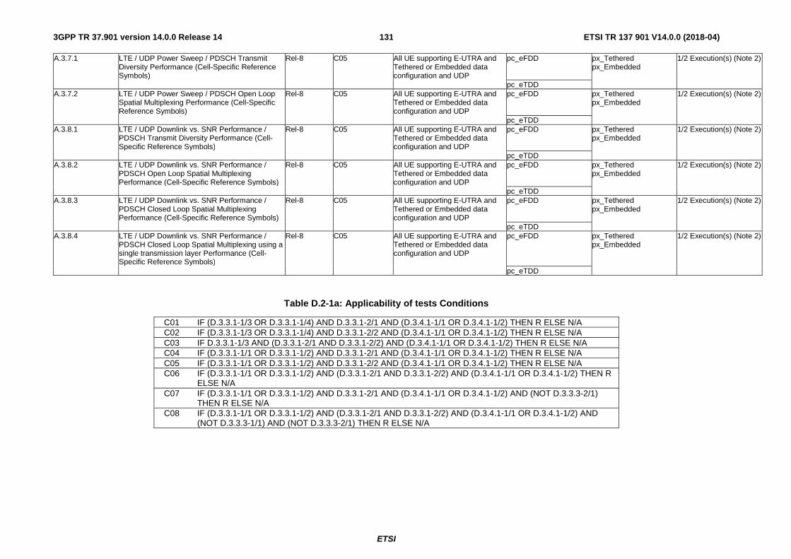
ETSI
ETSI TR 137 901 V14.0.0 (2018-04)1313GPP TR 37.901 version 14.0.0 Release 14
A.3.7.1 LTE / UDP Power Sweep / PDSCH Transmit Diversity Performance (Cell-Specific Reference Symbols)
Rel-8 C05 All UE supporting E-UTRA and Tethered or Embedded data configuration and UDP
pc_eFDD px_Tethered px_Embedded
1/2 Execution(s) (Note 2)
pc_eTDD A.3.7.2 LTE / UDP Power Sweep / PDSCH Open Loop
Spatial Multiplexing Performance (Cell-Specific Reference Symbols)
Rel-8 C05 All UE supporting E-UTRA and Tethered or Embedded data configuration and UDP
pc_eFDD px_Tethered px_Embedded
1/2 Execution(s) (Note 2)
pc_eTDD A.3.8.1 LTE / UDP Downlink vs. SNR Performance /
PDSCH Transmit Diversity Performance (Cell-Specific Reference Symbols)
Rel-8 C05 All UE supporting E-UTRA and Tethered or Embedded data configuration and UDP
pc_eFDD px_Tethered px_Embedded
1/2 Execution(s) (Note 2)
pc_eTDD A.3.8.2 LTE / UDP Downlink vs. SNR Performance /
PDSCH Open Loop Spatial Multiplexing Performance (Cell-Specific Reference Symbols)
Rel-8 C05 All UE supporting E-UTRA and Tethered or Embedded data configuration and UDP
pc_eFDD px_Tethered px_Embedded
1/2 Execution(s) (Note 2)
pc_eTDD A.3.8.3 LTE / UDP Downlink vs. SNR Performance /
PDSCH Closed Loop Spatial Multiplexing Performance (Cell-Specific Reference Symbols)
Rel-8 C05 All UE supporting E-UTRA and Tethered or Embedded data configuration and UDP
pc_eFDD px_Tethered px_Embedded
1/2 Execution(s) (Note 2)
pc_eTDD A.3.8.4 LTE / UDP Downlink vs. SNR Performance /
PDSCH Closed Loop Spatial Multiplexing using a single transmission layer Performance (Cell-Specific Reference Symbols)
Rel-8 C05 All UE supporting E-UTRA and Tethered or Embedded data configuration and UDP
pc_eFDD px_Tethered px_Embedded
1/2 Execution(s) (Note 2)
pc_eTDD
Table D.2-1a: Applicability of tests Conditions
C01 IF (D.3.3.1-1/3 OR D.3.3.1-1/4) AND D.3.3.1-2/1 AND (D.3.4.1-1/1 OR D.3.4.1-1/2) THEN R ELSE N/A C02 IF (D.3.3.1-1/3 OR D.3.3.1-1/4) AND D.3.3.1-2/2 AND (D.3.4.1-1/1 OR D.3.4.1-1/2) THEN R ELSE N/A C03 IF D.3.3.1-1/3 AND (D.3.3.1-2/1 AND D.3.3.1-2/2) AND (D.3.4.1-1/1 OR D.3.4.1-1/2) THEN R ELSE N/A C04 IF (D.3.3.1-1/1 OR D.3.3.1-1/2) AND D.3.3.1-2/1 AND (D.3.4.1-1/1 OR D.3.4.1-1/2) THEN R ELSE N/A C05 IF (D.3.3.1-1/1 OR D.3.3.1-1/2) AND D.3.3.1-2/2 AND (D.3.4.1-1/1 OR D.3.4.1-1/2) THEN R ELSE N/A C06 IF (D.3.3.1-1/1 OR D.3.3.1-1/2) AND (D.3.3.1-2/1 AND D.3.3.1-2/2) AND (D.3.4.1-1/1 OR D.3.4.1-1/2) THEN R
ELSE N/A C07 IF (D.3.3.1-1/1 OR D.3.3.1-1/2) AND D.3.3.1-2/1 AND (D.3.4.1-1/1 OR D.3.4.1-1/2) AND (NOT D.3.3.3-2/1)
THEN R ELSE N/A C08 IF (D.3.3.1-1/1 OR D.3.3.1-1/2) AND (D.3.3.1-2/1 AND D.3.3.1-2/2) AND (D.3.4.1-1/1 OR D.3.4.1-1/2) AND
(NOT D.3.3.3-1/1) AND (NOT D.3.3.3-2/1) THEN R ELSE N/A
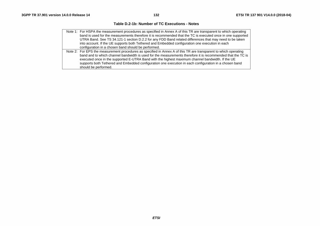
ETSI
ETSI TR 137 901 V14.0.0 (2018-04)1323GPP TR 37.901 version 14.0.0 Release 14
Table D.2-1b: Number of TC Executions - Notes
Note 1: For HSPA the measurement procedures as specified in Annex A of this TR are transparent to which operating band is used for the measurements therefore it is recommended that the TC is executed once in one supported UTRA Band. See TS 34.121-1 section D.2.2 for any FDD Band related differences that may need to be taken into account. If the UE supports both Tethered and Embedded configuration one execution in each configuration in a chosen band should be performed.
Note 2: For EPS the measurement procedures as specified in Annex A of this TR are transparent to which operating band and to which channel bandwidth is used for the measurements therefore it is recommended that the TC is executed once in the supported E-UTRA Band with the highest maximum channel bandwidth. If the UE supports both Tethered and Embedded configuration one execution in each configuration in a chosen band should be performed.
ETSI
ETSI TR 137 901 V14.0.0 (2018-04)1333GPP TR 37.901 version 14.0.0 Release 14
D.3 ICS / IXIT proforma
D.3.1 General
D.3.1.1 Introduction
The purposes of an ICS and IXIT proformas are to provide mechanism whereby a supplier of an implementation of the requirements defined in relevant specifications may provide information about the implementation in regard to protocol capabilities or extra information needed for testing in a standardised manner.
Due to the nature of the present document a complete ICS proforma is not specified and instead only the ICS proforma tables needed for the TC applicability defined in D.2 are included. If such might be needed by an implementation supplier or an organisation that may like to conduct UE Application Layer Data Throughput Performance assessment an example of the parts of a complete ICS proforma omitted here can be found e.g. in TS 36.523-2.
D.3.1.2 Abbreviations and conventions
The partial ICS / IXIT proforma contained in this annex is comprised of information in tabular form with the meaning of the separate table columns as follows:
Item column
The item column contains a number which identifies the item in the table.
Item description column
The item description column describes in free text each respective item (e.g. parameters, timers, etc.). It implicitly means "is <item description> supported by the implementation?".
Reference column
The reference column gives reference to the relevant 3GPP core specifications.
Release column
The release column indicates the earliest release from which the capability or option is relevant.
Mnemonic column
The Mnemonic column contains mnemonic identifiers for each item.
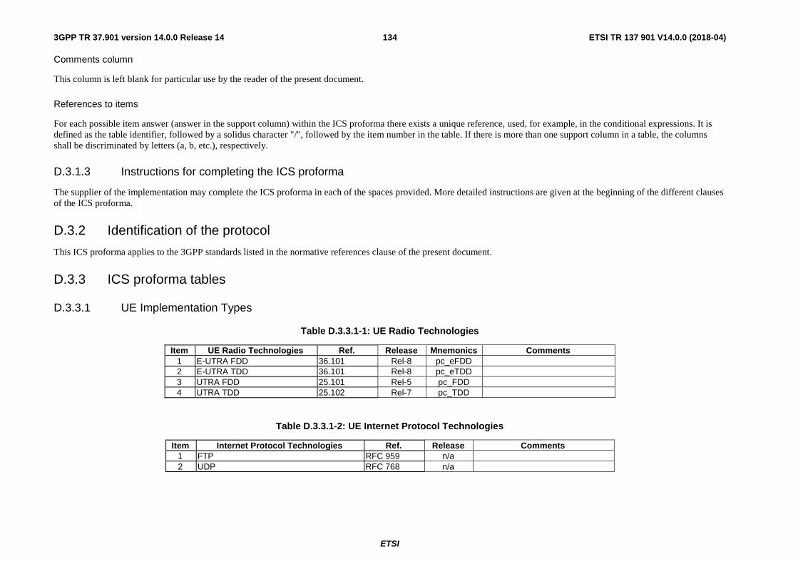
ETSI
ETSI TR 137 901 V14.0.0 (2018-04)1343GPP TR 37.901 version 14.0.0 Release 14
Comments column
This column is left blank for particular use by the reader of the present document.
References to items
For each possible item answer (answer in the support column) within the ICS proforma there exists a unique reference, used, for example, in the conditional expressions. It is defined as the table identifier, followed by a solidus character "/", followed by the item number in the table. If there is more than one support column in a table, the columns shall be discriminated by letters (a, b, etc.), respectively.
D.3.1.3 Instructions for completing the ICS proforma
The supplier of the implementation may complete the ICS proforma in each of the spaces provided. More detailed instructions are given at the beginning of the different clauses of the ICS proforma.
D.3.2 Identification of the protocol
This ICS proforma applies to the 3GPP standards listed in the normative references clause of the present document.
D.3.3 ICS proforma tables
D.3.3.1 UE Implementation Types
Table D.3.3.1-1: UE Radio Technologies
Item UE Radio Technologies Ref. Release Mnemonics Comments 1 E-UTRA FDD 36.101 Rel-8 pc_eFDD 2 E-UTRA TDD 36.101 Rel-8 pc_eTDD 3 UTRA FDD 25.101 Rel-5 pc_FDD 4 UTRA TDD 25.102 Rel-7 pc_TDD
Table D.3.3.1-2: UE Internet Protocol Technologies
Item Internet Protocol Technologies Ref. Release Comments 1 FTP RFC 959 n/a 2 UDP RFC 768 n/a
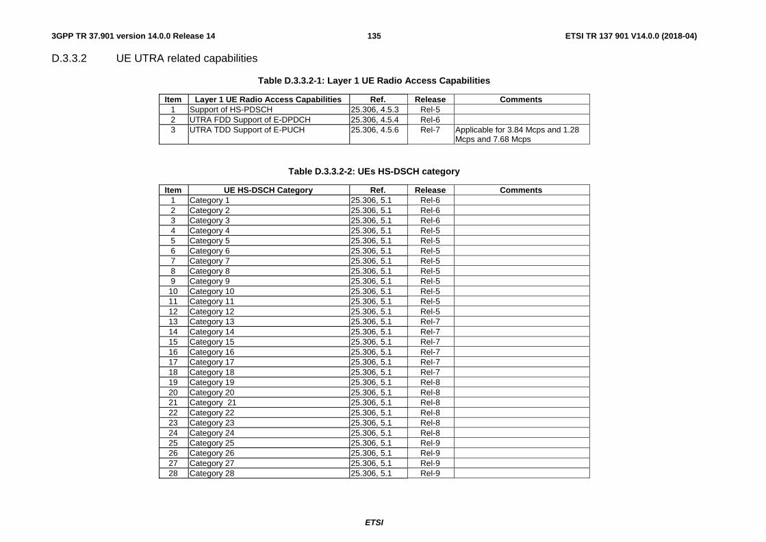
ETSI
ETSI TR 137 901 V14.0.0 (2018-04)1353GPP TR 37.901 version 14.0.0 Release 14
D.3.3.2 UE UTRA related capabilities
Table D.3.3.2-1: Layer 1 UE Radio Access Capabilities
Item Layer 1 UE Radio Access Capabilities Ref. Release Comments 1 Support of HS-PDSCH 25.306, 4.5.3 Rel-5 2 UTRA FDD Support of E-DPDCH 25.306, 4.5.4 Rel-6 3 UTRA TDD Support of E-PUCH 25.306, 4.5.6 Rel-7 Applicable for 3.84 Mcps and 1.28
Mcps and 7.68 Mcps
Table D.3.3.2-2: UEs HS-DSCH category
Item UE HS-DSCH Category Ref. Release Comments 1 Category 1 25.306, 5.1 Rel-6 2 Category 2 25.306, 5.1 Rel-6 3 Category 3 25.306, 5.1 Rel-6 4 Category 4 25.306, 5.1 Rel-5 5 Category 5 25.306, 5.1 Rel-5 6 Category 6 25.306, 5.1 Rel-5 7 Category 7 25.306, 5.1 Rel-5 8 Category 8 25.306, 5.1 Rel-5 9 Category 9 25.306, 5.1 Rel-5 10 Category 10 25.306, 5.1 Rel-5 11 Category 11 25.306, 5.1 Rel-5 12 Category 12 25.306, 5.1 Rel-5 13 Category 13 25.306, 5.1 Rel-7 14 Category 14 25.306, 5.1 Rel-7 15 Category 15 25.306, 5.1 Rel-7 16 Category 16 25.306, 5.1 Rel-7 17 Category 17 25.306, 5.1 Rel-7 18 Category 18 25.306, 5.1 Rel-7 19 Category 19 25.306, 5.1 Rel-8 20 Category 20 25.306, 5.1 Rel-8 21 Category 21 25.306, 5.1 Rel-8 22 Category 22 25.306, 5.1 Rel-8 23 Category 23 25.306, 5.1 Rel-8 24 Category 24 25.306, 5.1 Rel-8 25 Category 25 25.306, 5.1 Rel-9 26 Category 26 25.306, 5.1 Rel-9 27 Category 27 25.306, 5.1 Rel-9 28 Category 28 25.306, 5.1 Rel-9
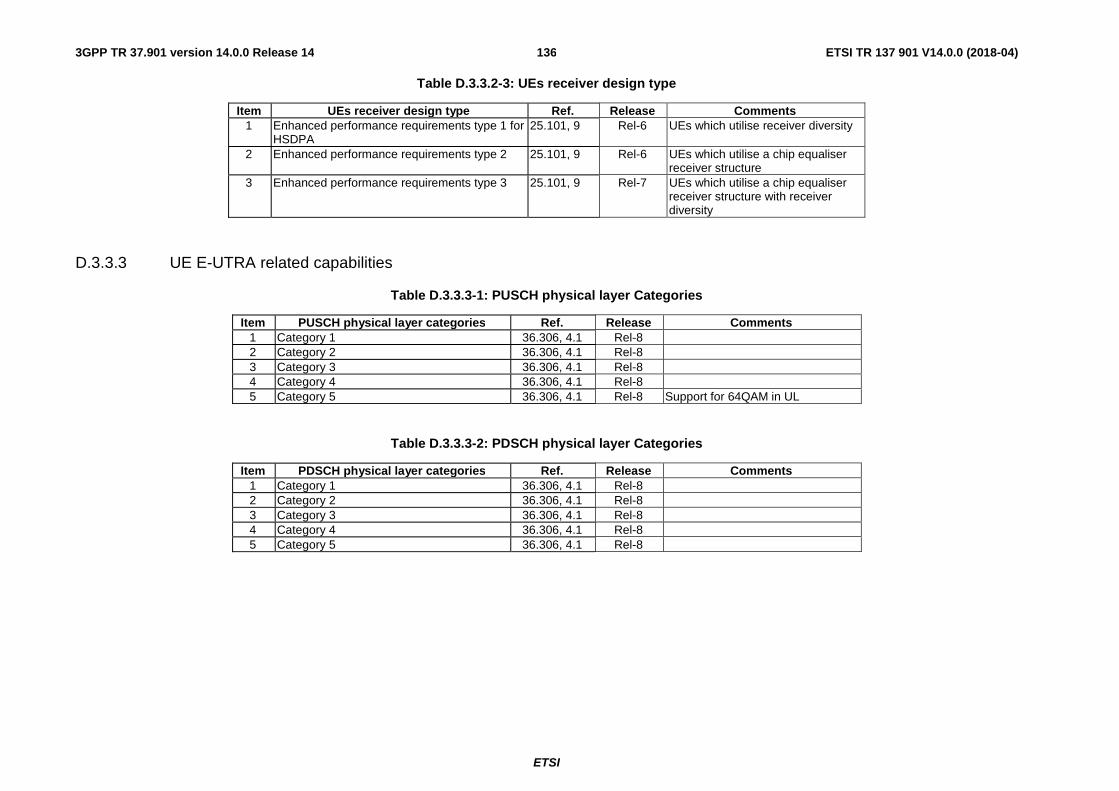
ETSI
ETSI TR 137 901 V14.0.0 (2018-04)1363GPP TR 37.901 version 14.0.0 Release 14
Table D.3.3.2-3: UEs receiver design type
Item UEs receiver design type Ref. Release Comments 1 Enhanced performance requirements type 1 for
HSDPA 25.101, 9 Rel-6 UEs which utilise receiver diversity
2 Enhanced performance requirements type 2 25.101, 9 Rel-6 UEs which utilise a chip equaliser receiver structure
3 Enhanced performance requirements type 3 25.101, 9 Rel-7 UEs which utilise a chip equaliser receiver structure with receiver diversity
D.3.3.3 UE E-UTRA related capabilities
Table D.3.3.3-1: PUSCH physical layer Categories
Item PUSCH physical layer categories Ref. Release Comments 1 Category 1 36.306, 4.1 Rel-8 2 Category 2 36.306, 4.1 Rel-8 3 Category 3 36.306, 4.1 Rel-8 4 Category 4 36.306, 4.1 Rel-8 5 Category 5 36.306, 4.1 Rel-8 Support for 64QAM in UL
Table D.3.3.3-2: PDSCH physical layer Categories
Item PDSCH physical layer categories Ref. Release Comments 1 Category 1 36.306, 4.1 Rel-8 2 Category 2 36.306, 4.1 Rel-8 3 Category 3 36.306, 4.1 Rel-8 4 Category 4 36.306, 4.1 Rel-8 5 Category 5 36.306, 4.1 Rel-8
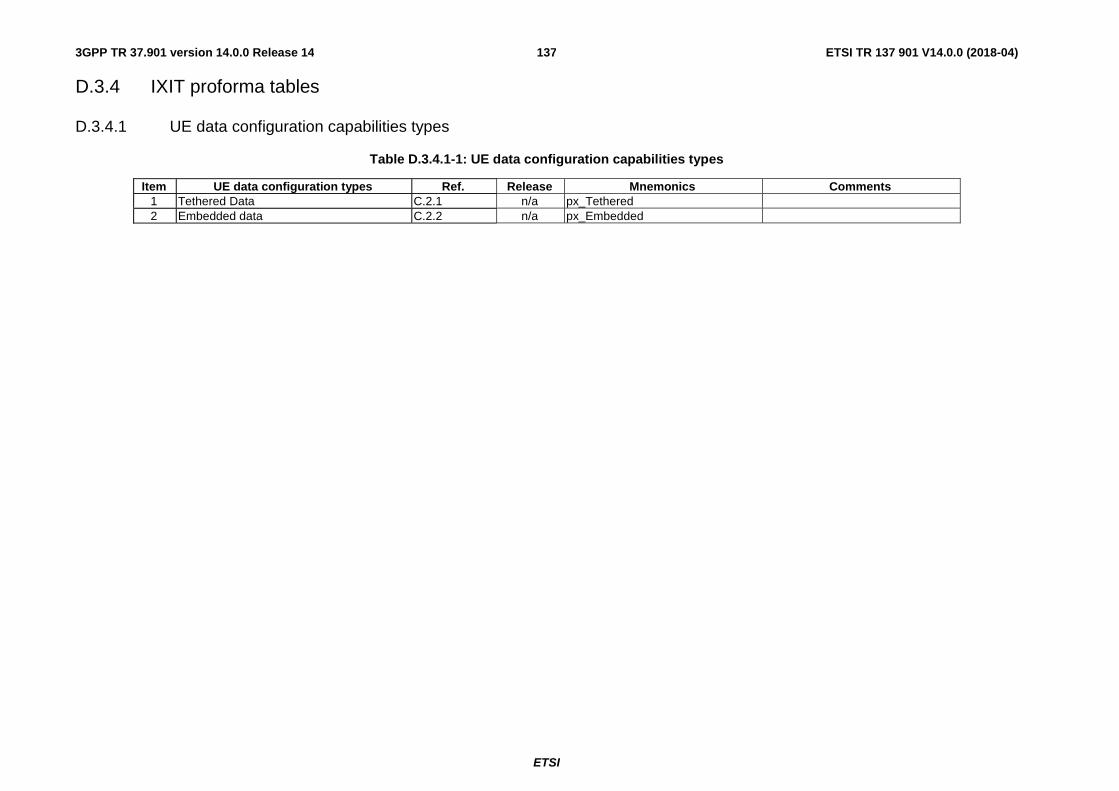
ETSI
ETSI TR 137 901 V14.0.0 (2018-04)1373GPP TR 37.901 version 14.0.0 Release 14
D.3.4 IXIT proforma tables
D.3.4.1 UE data configuration capabilities types
Table D.3.4.1-1: UE data configuration capabilities types
Item UE data configuration types Ref. Release Mnemonics Comments 1 Tethered Data C.2.1 n/a px_Tethered 2 Embedded data C.2.2 n/a px_Embedded
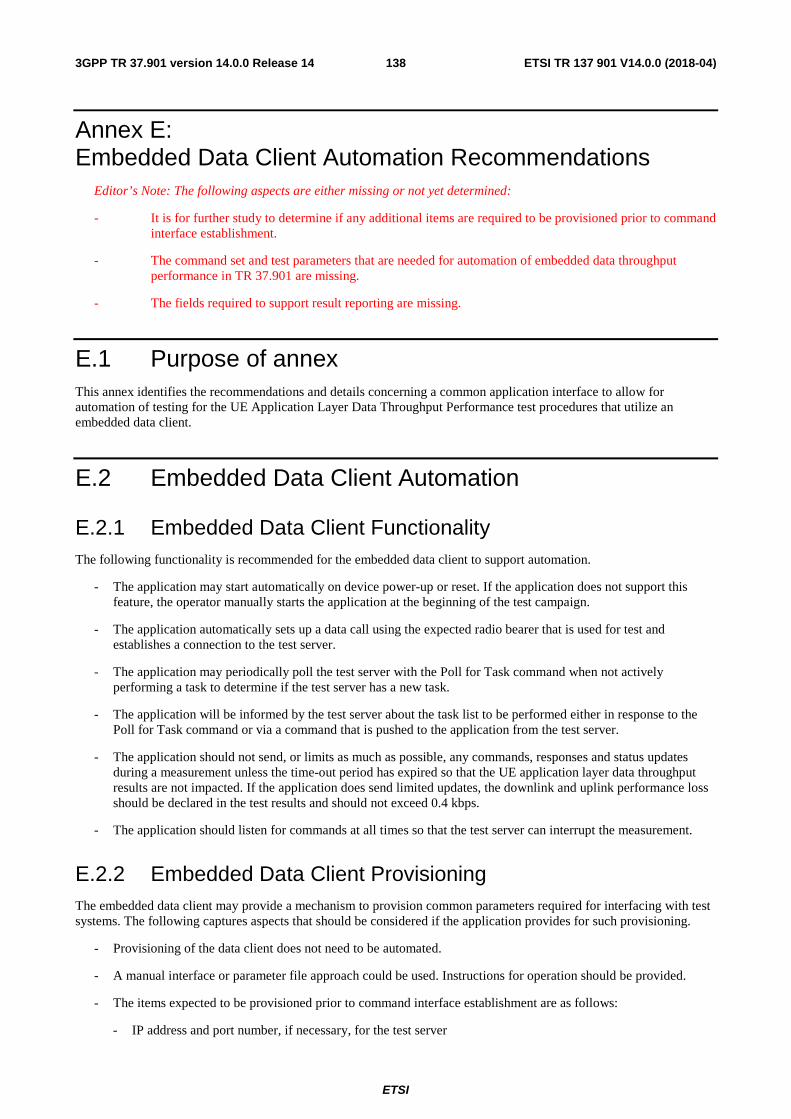
ETSI
ETSI TR 137 901 V14.0.0 (2018-04)1383GPP TR 37.901 version 14.0.0 Release 14
Annex E: Embedded Data Client Automation Recommendations
Editor’s Note: The following aspects are either missing or not yet determined:
- It is for further study to determine if any additional items are required to be provisioned prior to command interface establishment.
- The command set and test parameters that are needed for automation of embedded data throughput performance in TR 37.901 are missing.
- The fields required to support result reporting are missing.
E.1 Purpose of annex This annex identifies the recommendations and details concerning a common application interface to allow for automation of testing for the UE Application Layer Data Throughput Performance test procedures that utilize an embedded data client.
E.2 Embedded Data Client Automation
E.2.1 Embedded Data Client Functionality The following functionality is recommended for the embedded data client to support automation.
- The application may start automatically on device power-up or reset. If the application does not support this feature, the operator manually starts the application at the beginning of the test campaign.
- The application automatically sets up a data call using the expected radio bearer that is used for test and establishes a connection to the test server.
- The application may periodically poll the test server with the Poll for Task command when not actively performing a task to determine if the test server has a new task.
- The application will be informed by the test server about the task list to be performed either in response to the Poll for Task command or via a command that is pushed to the application from the test server.
- The application should not send, or limits as much as possible, any commands, responses and status updates during a measurement unless the time-out period has expired so that the UE application layer data throughput results are not impacted. If the application does send limited updates, the downlink and uplink performance loss should be declared in the test results and should not exceed 0.4 kbps.
- The application should listen for commands at all times so that the test server can interrupt the measurement.
E.2.2 Embedded Data Client Provisioning The embedded data client may provide a mechanism to provision common parameters required for interfacing with test systems. The following captures aspects that should be considered if the application provides for such provisioning.
- Provisioning of the data client does not need to be automated.
- A manual interface or parameter file approach could be used. Instructions for operation should be provided.
- The items expected to be provisioned prior to command interface establishment are as follows:
- IP address and port number, if necessary, for the test server
ETSI
ETSI TR 137 901 V14.0.0 (2018-04)1393GPP TR 37.901 version 14.0.0 Release 14
- Poll for Task Command Polling Period (if the polling approach is used, this may be a configurable item or a hardcoded value)
- FFS
If certain parameters are hard-coded, these parameters should be documented to allow for the test systems to be properly configured.
E.2.3 Embedded Data Client Command Set and Operation The embedded data client should use the specified command set and follow the operational structure defined in this clause.
E.2.3.1 Poll for Task Command
The embedded data client application may make use of a polling mechanism to query the test server for tasks to perform. If polling is used, the following instructions apply.
The Poll for Task command shall be substantiated with FFS.
If there is no task for the application to perform, an FFS error is returned. The application shall start its Waiting for Task Polling Period timer. When the timer expires, another Poll for Task command shall be sent.
If there is a task for the application to perform, the test server may return an FFS.
E.2.3.2 Task List
The test server will deliver a task list to the application. The task list will be delivered over the IP connection using HTTP(S) or raw TCP. The task list can contain multiple tasks that are listed sequentially for the application to execute or can also contain a single task. The format for the task list is XML for ASCII text string.
For each task, the following lists the valid parameters and valid strings for each parameter. The list of items should be considered as logical representations of the required parameters and content. The actual syntax may vary. The instructions for the application should provide the recommended usage for each particular test type.
- FFS
If the requested task list is unknown to the application, the application may ignore it or return an error of FFS. The application will then go back to a waiting for command state.
E.2.3.3 Result Reporting
Upon completion of the specified test sequence, the application shall upload the test results to the test server over the IP connection using HTTP(S) POST or raw TCP.
The result files shall be in CSV or XML format. The fields required to support result reporting are FFS.
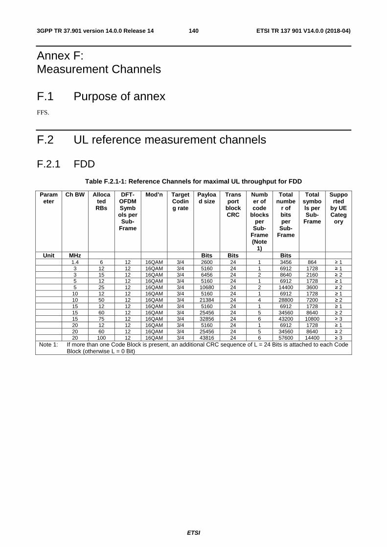
ETSI
ETSI TR 137 901 V14.0.0 (2018-04)1403GPP TR 37.901 version 14.0.0 Release 14
Annex F: Measurement Channels
F.1 Purpose of annex FFS.
F.2 UL reference measurement channels
F.2.1 FDD
Table F.2.1-1: Reference Channels for maximal UL throughput for FDD
Parameter
Ch BW Allocated RBs
DFT-OFDM Symb
ols per Sub-
Frame
Mod’n Target Coding rate
Payload size
Transport
block CRC
Number of code
blocks per
Sub-Frame (Note
1)
Total numbe
r of bits per
Sub-Frame
Total symbols per Sub-
Frame
Supported
by UE Categ
ory
Unit MHz Bits Bits Bits 1.4 6 12 16QAM 3/4 2600 24 1 3456 864 ≥ 1 3 12 12 16QAM 3/4 5160 24 1 6912 1728 ≥ 1 3 15 12 16QAM 3/4 6456 24 2 8640 2160 ≥ 2 5 12 12 16QAM 3/4 5160 24 1 6912 1728 ≥ 1 5 25 12 16QAM 3/4 10680 24 2 14400 3600 ≥ 2 10 12 12 16QAM 3/4 5160 24 1 6912 1728 ≥ 1 10 50 12 16QAM 3/4 21384 24 4 28800 7200 ≥ 2 15 12 12 16QAM 3/4 5160 24 1 6912 1728 ≥ 1 15 60 12 16QAM 3/4 25456 24 5 34560 8640 ≥ 2 15 75 12 16QAM 3/4 32856 24 6 43200 10800 ≥ 3 20 12 12 16QAM 3/4 5160 24 1 6912 1728 ≥ 1 20 60 12 16QAM 3/4 25456 24 5 34560 8640 ≥ 2 20 100 12 16QAM 3/4 43816 24 6 57600 14400 ≥ 3
Note 1: If more than one Code Block is present, an additional CRC sequence of L = 24 Bits is attached to each Code Block (otherwise L = 0 Bit)
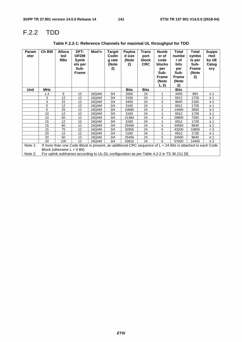
ETSI
ETSI TR 137 901 V14.0.0 (2018-04)1413GPP TR 37.901 version 14.0.0 Release 14
F.2.2 TDD
Table F.2.2-1: Reference Channels for maximal UL throughput for TDD
Parameter
Ch BW Allocated RBs
DFT-OFDM Symb
ols per Sub-
Frame
Mod’n Target Coding rate (Note
2)
Payload size (Note
2)
Transport
block CRC
Number of code
blocks per
Sub-Frame (Note 1, 2)
Total numbe
r of bits per
Sub-Frame (Note
2)
Total symbols per Sub-
Frame (Note
2)
Supported
by UE Categ
ory
Unit MHz Bits Bits Bits 1.4 6 12 16QAM 3/4 2600 24 1 3456 864 ≥ 1 3 12 12 16QAM 3/4 5160 24 1 6912 1728 ≥ 1 3 15 12 16QAM 3/4 6456 24 2 8640 2160 ≥ 2 5 12 12 16QAM 3/4 5160 24 1 6912 1728 ≥ 1 5 25 12 16QAM 3/4 10680 24 2 14400 3600 ≥ 2 10 12 12 16QAM 3/4 5160 24 1 6912 1728 ≥ 1 10 50 12 16QAM 3/4 21384 24 4 28800 7200 ≥ 2 15 12 12 16QAM 3/4 5160 24 1 6912 1728 ≥ 1 15 60 12 16QAM 3/4 25456 24 5 34560 8640 ≥ 2 15 75 12 16QAM 3/4 32856 24 6 43200 10800 ≥ 3 20 12 12 16QAM 3/4 5160 24 1 6912 1728 ≥ 1 20 60 12 16QAM 3/4 25456 24 5 34560 8640 ≥ 2 20 100 12 16QAM 3/4 43816 24 6 57600 14400 ≥ 3
Note 1: If more than one Code Block is present, an additional CRC sequence of L = 24 Bits is attached to each Code Block (otherwise L = 0 Bit)
Note 2: For uplink subframes according to UL-DL configuration as per Table 4.2-2 in TS 36.211 [9]

ETSI
ETSI TR 137 901 V14.0.0 (2018-04)1423GPP TR 37.901 version 14.0.0 Release 14
Annex G: Change history
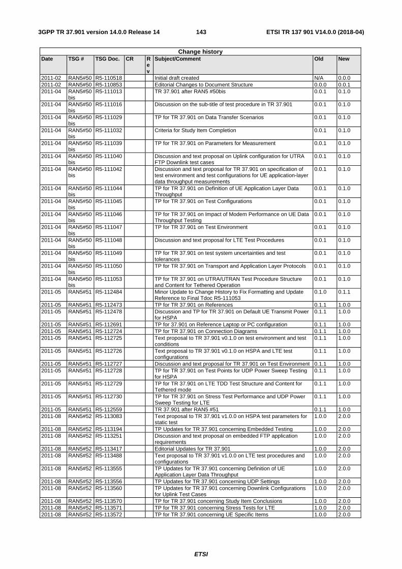
ETSI
ETSI TR 137 901 V14.0.0 (2018-04)1433GPP TR 37.901 version 14.0.0 Release 14
Change history Date TSG # TSG Doc. CR R
ev
Subject/Comment Old New
2011-02 RAN5#50 R5-110518 Initial draft created N/A 0.0.0 2011-02 RAN5#50 R5-110853 Editorial Changes to Document Structure 0.0.0 0.0.1 2011-04 RAN5#50
bis R5-111013 TR 37.901 after RAN5 #50bis 0.0.1 0.1.0
2011-04 RAN5#50bis
R5-111016 Discussion on the sub-title of test procedure in TR 37.901 0.0.1 0.1.0
2011-04 RAN5#50bis
R5-111029 TP for TR 37.901 on Data Transfer Scenarios 0.0.1 0.1.0
2011-04 RAN5#50bis
R5-111032 Criteria for Study Item Completion 0.0.1 0.1.0
2011-04 RAN5#50bis
R5-111039 TP for TR 37.901 on Parameters for Measurement 0.0.1 0.1.0
2011-04 RAN5#50bis
R5-111040 Discussion and text proposal on Uplink configuration for UTRA FTP Downlink test cases
0.0.1 0.1.0
2011-04 RAN5#50bis
R5-111042 Discussion and text proposal for TR 37.901 on specification of test environment and test configurations for UE application-layer data throughput measurements
0.0.1 0.1.0
2011-04 RAN5#50bis
R5-111044 TP for TR 37.901 on Definition of UE Application Layer Data Throughput
0.0.1 0.1.0
2011-04 RAN5#50bis
R5-111045 TP for TR 37.901 on Test Configurations 0.0.1 0.1.0
2011-04 RAN5#50bis
R5-111046 TP for TR 37.901 on Impact of Modem Performance on UE Data Throughput Testing
0.0.1 0.1.0
2011-04 RAN5#50bis
R5-111047 TP for TR 37.901 on Test Environment 0.0.1 0.1.0
2011-04 RAN5#50bis
R5-111048 Discussion and text proposal for LTE Test Procedures 0.0.1 0.1.0
2011-04 RAN5#50bis
R5-111049 TP for TR 37.901 on test system uncertainties and test tolerances
0.0.1 0.1.0
2011-04 RAN5#50bis
R5-111050 TP for TR 37.901 on Transport and Application Layer Protocols 0.0.1 0.1.0
2011-04 RAN5#50bis
R5-111053 TP for TR 37.901 on UTRA/UTRAN Test Procedure Structure and Content for Tethered Operation
0.0.1 0.1.0
2011-05 RAN5#51 R5-112484 Minor Update to Change History to Fix Formatting and Update Reference to Final Tdoc R5-111053
0.1.0 0.1.1
2011-05 RAN5#51 R5-112473 TP for TR 37.901 on References 0.1.1 1.0.0 2011-05 RAN5#51 R5-112478 Discussion and TP for TR 37.901 on Default UE Transmit Power
for HSPA 0.1.1 1.0.0
2011-05 RAN5#51 R5-112691 TP for 37.901 on Reference Laptop or PC configuration 0.1.1 1.0.0 2011-05 RAN5#51 R5-112724 TP for TR 37.901 on Connection Diagrams 0.1.1 1.0.0 2011-05 RAN5#51 R5-112725 Text proposal to TR 37.901 v0.1.0 on test environment and test
conditions 0.1.1 1.0.0
2011-05 RAN5#51 R5-112726 Text proposal to TR 37.901 v0.1.0 on HSPA and LTE test configurations
0.1.1 1.0.0
2011-05 RAN5#51 R5-112727 Discussion and text proposal for TR 37.901 on Test Environment 0.1.1 1.0.0 2011-05 RAN5#51 R5-112728 TP for TR 37.901 on Test Points for UDP Power Sweep Testing
for HSPA 0.1.1 1.0.0
2011-05 RAN5#51 R5-112729 TP for TR 37.901 on LTE TDD Test Structure and Content for Tethered mode
0.1.1 1.0.0
2011-05 RAN5#51 R5-112730 TP for TR 37.901 on Stress Test Performance and UDP Power Sweep Testing for LTE
0.1.1 1.0.0
2011-05 RAN5#51 R5-112559 TR 37.901 after RAN5 #51 0.1.1 1.0.0 2011-08 RAN5#52 R5-113083 Text proposal to TR 37.901 v1.0.0 on HSPA test parameters for
static test 1.0.0 2.0.0
2011-08 RAN5#52 R5-113194 TP Updates for TR 37.901 concerning Embedded Testing 1.0.0 2.0.0 2011-08 RAN5#52 R5-113251 Discussion and text proposal on embedded FTP application
requirements 1.0.0 2.0.0
2011-08 RAN5#52 R5-113417 Editorial Updates for TR 37.901 1.0.0 2.0.0 2011-08 RAN5#52 R5-113488 Text proposal to TR 37.901 v1.0.0 on LTE test procedures and
configurations 1.0.0 2.0.0
2011-08 RAN5#52 R5-113555 TP Updates for TR 37.901 concerning Definition of UE Application Layer Data Throughput
1.0.0 2.0.0
2011-08 RAN5#52 R5-113556 TP Updates for TR 37.901 concerning UDP Settings 1.0.0 2.0.0 2011-08 RAN5#52 R5-113560 TP Updates for TR 37.901 concerning Downlink Configurations
for Uplink Test Cases 1.0.0 2.0.0
2011-08 RAN5#52 R5-113570 TP for TR 37.901 concerning Study Item Conclusions 1.0.0 2.0.0 2011-08 RAN5#52 R5-113571 TP for TR 37.901 concerning Stress Tests for LTE 1.0.0 2.0.0 2011-08 RAN5#52 R5-113572 TP for TR 37.901 concerning UE Specific Items 1.0.0 2.0.0
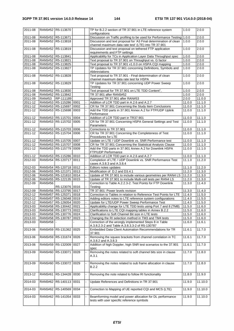
ETSI
ETSI TR 137 901 V14.0.0 (2018-04)1443GPP TR 37.901 version 14.0.0 Release 14
2011-08 RAN5#52 R5-113670 TP for B.2.2 section of TR 37.901 in LTE reference system configurations
1.0.0 2.0.0
2011-08 RAN5#52 R5-113671 Discussion on Traffic profiling to be used for Performance Testing 1.0.0 2.0.0 2011-08 RAN5#52 R5-113818 Discussion and text proposal for ‘A3 Final determination of clean
channel maximum data rate test’ (LTE) into TR 37.901 1.0.0 2.0.0
2011-08 RAN5#52 R5-113819 Discussion and text proposal on tethered FTP application requirements and FTP settings
1.0.0 2.0.0
2011-08 RAN5#52 R5-113841 Applicability for TCs in Application Layer Data Throughput spec 1.0.0 2.0.0 2011-08 RAN5#52 R5-113821 Text proposal to TR 37.901 on Throughput vs. G factor 1.0.0 2.0.0 2011-08 RAN5#52 R5-113825 Text proposal to TR 37.901 v1.0.0 on HSPA CQI mapping 1.0.0 2.0.0 2011-08 RAN5#52 R5-113827 TP Updates for TR 37.901 concerning Definitions, Symbols and
Abbreviations 1.0.0 2.0.0
2011-08 RAN5#52 R5-113828 Text proposal to TR 37.901 - Final determination of clean channel maximum data rate test for HSPA
1.0.0 2.0.0
2011-08 RAN5#52 R5-113829 TP Updates for TR 37.901 concerning UDP Power Sweep Testing
1.0.0 2.0.0
2011-08 RAN5#52 R5-113830 Text proposal for TR 37.901 on LTE TDD Content", 1.0.0 2.0.0 2011-08 RAN5#52 R5-113842 TR 37.901 after RAN5#52 1.0.0 2.0.0 2011-09 RAN#53 RP-111189 Approved TR 37.901 after RAN#53 2.0.0 11.0.0 2011-12 RAN5#53 R5-115286 0001 - Addition of LCR TDD part in A.2.6 and A.2.7 11.0.0 11.1.0 2011-12 RAN5#53 R5-115697 0002 - CR for TR 37.901 Concerning the Study Item Conclusions 11.0.0 11.1.0 2011-12 RAN5#53 R5-115698 0003 - Add the TDD parts in 37.901 Annex A.2 for FTP/UDP Uplink
Performance 11.0.0 11.1.0
2011-12 RAN5#53 R5-115701 0004 - Addition of LCR TDD part in TR37.901 11.0.0 11.1.0 2011-12 RAN5#53 R5-115702 0005 - CR for TR 37.901 Concerning HSPA General Settings and Test
Parameters 11.0.0 11.1.0
2011-12 RAN5#53 R5-115703 0006 - Corrections to TR 37.901 11.0.0 11.1.0 2011-12 RAN5#53 R5-115704 0006 - CR for TR 37.901 Concerning the Completeness of Test
Procedures for LTE 11.0.0 11.1.0
2011-12 RAN5#53 R5-115705 0007 - Update on LTE / UDP Downlink vs. SNR Performance test 11.0.0 11.1.0 2011-12 RAN5#53 R5-115707 0008 - CR for TR 37.901 Concerning the Statistical Analysis Clause 11.0.0 11.1.0 2011-12 RAN5#53 R5-115779 0009 - Add the TDD parts in 37.901 Annex A.2 for Downlink HSPA
FTP/UDP Performance 11.0.0 11.1.0
2011-12 RAN5#53 R5-115286 0010 - Addition of LCR TDD part in A.2.6 and A.2.7 11.0.0 11.1.0 2012-03 RAN5#54 R5-120717 0011 - Completion of LTE / UDP Downlink vs. SNR Performance Test
cases A.3.8.3 and A.3.8.4 11.1.0 11.2.0
2012-03 RAN5#54 R5-120718 0012 - Editors notes updates 11.1.0 11.2.0 2012-06 RAN5#55 R5-121371 0013 - Modification of D.2 and D3.4.1 11.2.0 11.3.0 2012-06 RAN5#55 R5-121810 0014 - Update of TR 37.901 to include various geometries per RAN4 LS 11.2.0 11.3.0 2012-06 RAN5#55 R5-122135 0015 - Update of TR 37.901 to include Multi-cell tests per RAN4 LS 11.2.0 11.3.0 2012-09 RAN5#56
R5-123076 0016 - Correction to Table A.2.2.3-2: Test Points for FTP Downlink Testing
11.3.0 11.4.0
2012-09 RAN5#56 R5-123795 0017 - TR 37.901: Power levels revision 11.3.0 11.4.0 2012-12 RAN5#57 R5-125371 0018 - Correction to Tables in relation to Reference Test Points for LTE 11.4.0 11.5.0 2012-12 RAN5#57 R5-126048 0019 - Adding editors notes to LTE reference system configurations 11.4.0 11.5.0 2012-12 RAN5#57 R5-126054 0020 - Update for LTE/UDP Power Sweep Performance Test 11.4.0 11.5.0 2013-03 RAN5#58 R5-130442 0021 - Applicability change for LTE TDD tests using Port 7 and 8 (TM8) 11.5.0 11.6.0 2013-03 RAN5#58 R5-130773 0022 - Clarifications to LTE CQI mapping tables in Annex B.2.2 11.5.0 11.6.0 2013-03 RAN5#58 R5-130776 0024 - Clarification to Soft Channel Bit size in LTE tests 11.5.0 11.6.0 2013-03 RAN5#58 R5-130787 0023 - Changing the RI selection method in TM3 and TM4 tests 11.5.0 11.6.0 2013-03 RAN5#58 - - - Correction of the wrongly implemented Steps 8 in Table
A.3.8.2.3-2 and Table A.3.8.3.3-2 of R5-130787 11.6.0 11.6.1
2013-06 RAN5#59 R5-131362 0025 - Embedded Data Client Automation Recommendations for TR 37.901
11.6.1 11.7.0
2013-06 RAN5#59 R5-131674 0026 - Removing the square brackets from channel correlation in TC A.3.8.2 and A.3.8.3
11.6.1 11.7.0
2013-06 RAN5#59 R5-132009 0027 - Addition of high Doppler, high SNR test scenarios to the 37.901 spec
11.6.1 11.7.0
2013-09 RAN5#60 R5-133071 0028 - Removing the notes related to soft channel bits size in clause A.3.1
11.7.0 11.8.0
2013-09 RAN5#60 R5-133072 0029 - Removing the notes related to sub frame allocation in clause B.2.2
11.7.0 11.8.0
2013-12 RAN5#61 R5-134428 0030 - Removing the note related to follow RI functionality 11.8.0 11.9.0
2014-03 RAN5#62 R5-140113 0031 - Update References and Definitions in TR 37.901 11.9.0 11.10.0
2014-03 RAN5#62 R5-140569 0034 - Correction to Mapping of UE reported CQI and MCS (LTE) 11.9.0 11.10.0
2014-03 RAN5#62 R5-141054 0033 - Beamforming model and power allocation for DL performance tests with user specific reference symbols
11.9.0 11.10.0
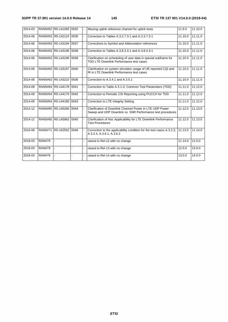
ETSI
ETSI TR 137 901 V14.0.0 (2018-04)1453GPP TR 37.901 version 14.0.0 Release 14
2014-03 RAN5#62 R5-141055 0032 - Missing uplink reference channel for uplink tests 11.9.0 11.10.0
2014-06 RAN5#63 R5-142124 0035 - Correction to Tables A.3.2.7.3-1 and A.3.3.7.3-1 11.10.0 11.11.0
2014-06 RAN5#63 R5-143194 0037 - Corrections to Symbol and Abbreviation references 11.10.0 11.11.0
2014-06 RAN5#63 R5-143195 0038 - Correction to Tables A.3.8.3.3-1 and A.3.8.4.3-1 11.10.0 11.11.0
2014-06 RAN5#63 R5-143196 0039 - Clarification on scheduling of user data in special subframe for TDD LTE Downlink Performance test cases
11.10.0 11.11.0
2014-06 RAN5#63 R5-143197 0040 - Clarification on system simulator usage of UE reported CQI and RI in LTE Downlink Performance test cases
11.10.0 11.11.0
2014-06 RAN5#63 R5-143210 0036 - Correction to A.3.4.1 and A.3.5.1 11.10.0 11.11.0
2014-09 RAN5#64 R5-144178 0041 - Correction to Table A.3.1-3: Common Test Parameters (TDD) 11.11.0 11.12.0
2014-09 RAN5#64 R5-144179 0042 - Correction to Periodic CSI Reporting using PUCCH for TDD 11.11.0 11.12.0
2014-09 RAN5#64 R5-144180 0043 - Correction to LTE Integrity Setting 11.11.0 11.12.0
2014-12 RAN5#65 R5-145266 0044 - Clarification of Downlink Channel Power in LTE UDP Power Sweep and UDP Downlink vs. SNR Performance test procedures
11.12.0 11.13.0
2014-12 RAN5#65 R5-145963 0045 - Clarification of Noc Applicability for LTE Downlink Performance Test Procedures
11.12.0 11.13.0
2016-06 RAN5#71 R5-162552 0046 - Correction to the applicability condition for the test cases A.3.2.3, A.3.2.4, A.3.6.1, A.3.6.2
11.13.0 11.14.0
2018-03 RAN#79 - - - raised to Rel-12 with no change 11.14.0 12.0.0
2018-03 RAN#79 - - - raised to Rel-13 with no change 12.0.0 13.0.0
2018-03 RAN#79 - - - raised to Rel-14 with no change 13.0.0 14.0.0

ETSI
ETSI TR 137 901 V14.0.0 (2018-04)1463GPP TR 37.901 version 14.0.0 Release 14
History
Document history
V14.0.0 April 2018 Publication