Embed Size (px)
Citation preview
MITSUBISHI ELECTRIC RESEARCH LABORATORIEShttp://www.merl.com
An LLC-Based Planar Wireless PowerTransfer System for Multiple Devices
Liu, N.; Wang, B.
TR2014-012 March 2014
Abstract
Wireless power transfer (WPT) technology has become a popular idea in battery charging forboth low- and high-power applications, such as mobile-phones and electric vehicles (EV). Forcharging portable devices, common ideas apply location sensing and turn on specific coils underthe loads. This paper proposes a universal WPT system for multiple electronics devices. Thesystem is based on LLC circuit, with an additional inductor added on the primary LC circuit,making the system less sensitive to load variations while maintaining a reasonable voltage-range.Parallel-connected transmitting coils provide independent charging for each load. A simple yeteffective variable-frequency control algorithm is used to provide maximum and balanced charg-ing power to the loads. Simulation results have demonstrated the advantages of the system–optimal operating frequency in a small range, simple control and independent charging for eachload. The hardware has been used to show the practicability of the system.
Applied Power Electronics Conference and Exposition (APEC)
This work may not be copied or reproduced in whole or in part for any commercial purpose. Permission to copy in whole or in partwithout payment of fee is granted for nonprofit educational and research purposes provided that all such whole or partial copies includethe following: a notice that such copying is by permission of Mitsubishi Electric Research Laboratories, Inc.; an acknowledgment ofthe authors and individual contributions to the work; and all applicable portions of the copyright notice. Copying, reproduction, orrepublishing for any other purpose shall require a license with payment of fee to Mitsubishi Electric Research Laboratories, Inc. Allrights reserved.
Copyright c©Mitsubishi Electric Research Laboratories, Inc., 2014201 Broadway, Cambridge, Massachusetts 02139

MERLCoverPageSide2

An LLC-Based Planar Wireless Power Transfer System
for Multiple Devices
Nan Liu1,2,§
, Bingnan Wang1,*
1Mitsubishi Electric Research Laboratories
201 Broadway, Suite 8
Cambridge, MA 02139, USA *[email protected]
2School of Electrical and Computer Engineering
Georgia Institute of Technology
Atlanta, GA 30332, USA §[email protected]
Abstract—Wireless power transfer (WPT) technology has
become a popular idea in battery charging for both low- and
high-power applications, such as mobile-phones and electric
vehicles (EV). For charging portable devices, common ideas
apply location sensing and turn on specific coils under the loads.
This paper proposes a universal WPT system for multiple
electronics devices. The system is based on LLC circuit, with an
additional inductor added on the primary LC circuit, making
the system less sensitive to load variations while maintaining a
reasonable voltage-range. Parallel-connected transmitting coils
provide independent charging for each load. A simple yet
effective variable-frequency control algorithm is used to provide
maximum and balanced charging power to the loads. Simulation
results have demonstrated the advantages of the system –
optimal operating frequency in a small range, simple control
and independent charging for each load. The hardware has been
used to show the practicability of the system.
I. INTRODUCTION
Wireless power transfer (WPT) technology is a promising method of battery charging for portable devices and electric vehicles, with its pros such as convenience and aesthetics. There are several kinds of wireless power transfer based on different methods such as inductive and conductive charging. Nowadays, a lot of inductive charging systems for electronic devices have been under research. Many wireless chargers are already on market, for example, the wireless charger for Nokia Lumia 920. Wireless Power Consortium (WPC) has been formed aiming at setting a new common platform for wireless power transfer. The WPC has also endorsed Part 1 of the world’s first international standard of wireless power transfer - ‘Qi’. The standard needs a designated planar area within which a load or several loads can be charged [1]. Consequently, a universal charging solution for various electronic products is desired for wireless charging of electronic products.
Several platform-designs and circuit-designs have been proposed in the WPT system for portable devices. In the ‘Qi’ standard, three wireless charging approaches have proposed, including guided positioning charging, free-positioning charging based on a mechanically movable transmitting coil and free-positioning charging based on selective excitation of
coil array [1]. Based on ‘Qi’ standard, in [2], a single-layer array coil structure is applied to charge one or more different portable electronics devices with a localized charging feature. In the design, additional sensors and switches are needed to ensure only the coils under load devices can be turned on. In addition, much more control is needed on tuning the resonant circuit, because the inductance of the primary side (primary inductance) can be changed by varied number of coils used for charging. In [3], parallel-connected transmitting coils (16cm 18cm) and several smaller secondary coils (6cm 8cm) are used to realize wireless charging with high efficiency in different positions. However, this work only analyzes the efficiency associated with coil-arrangement and uniform-flux generation and no control algorithm is provided. The size and shape of the receiving coils are also limited. In [4], a structure consisted of a spiral winding was proposed for charging one or multiple devices. Since the loads are series-connected, the variation of one load will affect others and lead to unbalanced charging among the loads. To the best of our knowledge, there are rarely papers that combine detailed analysis of the topology design, control and devices-coordination used for the universal WPT system of low-power devices.
In this paper, a WPT system is developed for charging a wide range of electronic devices. It provides free-positioning charging without necessity of location sensing or turning off unnecessary coils. The basic topology of the system is shown in the Fig. 1. The LLC circuit is used as the basic topology of the system, which acts as a controllable voltage source regardless of the load conditions. Four or more parallel-connected coils form the charging platform, further reducing the influence of load variations on the primary side. The parallel-connected charging coils allow independent charging of each load. A simple yet effective algorithm for variable-frequency control of the primary inverter is proposed, to realize the maximum power supply with a reasonable charging voltage. It has been demonstrated that the optimal frequency is limited in a very small range because of the reduced influence of load on the system. High-efficiency and maximum power-level have been realized in different load-conditions. A prototype is used to test the practicality of the system.
§The research was conducted during Nan Liu’s internship with
Mitsubishi Electric Research Laboratories.
II. SYSTEM TOPOLOGY ANALYSIS
A lot of research has been done on the design of the
charging coils, including the coils-shape, number of turns,
coil-arrangement, etc. In this work, we focus on the analysis
of system topology, instead of the design of coils. In our
analysis and experiment, square-shaped coils are used to
demonstrate our ideas. The formation of the coils and flux
generated are indicated in Fig. 2. Note that the flux of each
coil is of the same polarity.
A. Equivalent Topology of the WPT System
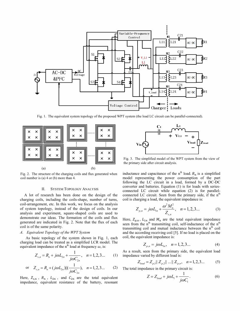
As basic topology of the system shown in Fig. 1, each charging load can be treated as a simplified LCR model. The equivalent impedance of the n
th load at frequency , is:
, 2
2
1, 1,2,3...s n n n
n
Z R j L nj C
(1)
or , 2
2
1( )||( ), 1,2,3...s n n n
n
Z R j L nj C
(2)
Here, , , , and are the total equivalent
impedance, equivalent resistance of the battery, resonant
inductance and capacitance of the nth
load. is a simplified model representing the power consumption of the part following the LC circuit in a load, formed by a DC-DC converter and batteries. Equation (1) is for loads with series-connected LC circuit while equation (2) is for parallel-connected LC circuit. Seen from the primary side, if the n
th
coil is charging a load, the equivalent impedance is:
2 2
, 1
,
, 1,2,3...np n n
s n
MZ j L n
Z
(3)
Here, , and are the total equivalent impedance
seen from the nth
transmitting coil, self-inductance of the nth
transmitting coil and mutual inductance between the nth coil
and the according receiving coil [5]. If no load is placed on the coil, the equivalent impedance is:
, 1 , 1,2,3...p n nZ j L n (4)
As a result, seen from the primary side, the equivalent load impedance varied by different load is:
,1 ,2 ,|| || ... || Z , 1,2,3...load p p p nZ Z Z n (5)
The total impedance in the primary circuit is:
1
1
1loadZ Z j L
j C
. (6)
Fig. 1. The equivalent system topology of the proposed WPT system (the load LC circuit can be parallel-connected).
(a) (b)
Fig. 2. The structure of the charging coils and flux generated when
coil number is (a) 4 or (b) more than 4.
Fig. 3. The simplified model of the WPT system from the view of
the primary side after circuit analysis.
The equivalent circuit of the system is shown in Fig. 3, where is the voltage of the load part in the primary side and is the input voltage of LC resonant circuit. The operating frequency of the inverter can be set as the resonant frequency of the system, which leads to a pure-resistive load (no reactive power output). For some of complicated control, the frequency may be shifted a little bit from the resonant frequency to realize soft-switching or higher output power.
B. Analysis of Different Load Conditions
As all of the transmitting coils are parallel-connected, each load can be charged independently with the same voltage – Vload. The most common load condition is that each of the receiving coils is placed right on one of the transmitting coils, as analyzed by (1) to (3). The no-load condition of the transmitting coils can be treated as a pure inductor, which has been indicated by (4). Moreover, to realize the free-positioning charging, more conditions should be analyzed, especially when one receiving coil is charged by multiple transmitting coils.
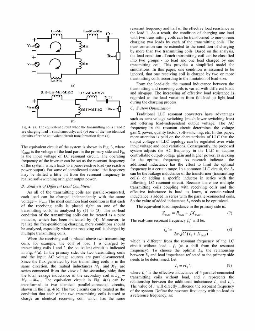
When the receiving coil is placed above two transmitting coils, for example, the coil of load 1 is charged by transmitting coils 1 and 2, the equivalent circuit is indicated in Fig. 4(a). In the primary side, the two transmitting coils and the input AC voltage sources are parallel-connected. Since the flux generated by two transmitting coils is in the same direction, the mutual inductances and are series-connected from the view of the secondary side; then the total leakage inductance of the secondary coil is . The equivalent circuit in Fig. 4(a) can be transformed to two identical parallel-connected circuits, shown in the Fig. 4(b). The two circuits can be treated as the condition that each of the two transmitting coils is used to charge an identical receiving coil, which has the same
resonant frequency and half of the effective load resistance as the load 1. As a result, the condition of charging one load with two transmitting coils can be transformed to one-on-one charging two loads by each of the transmitting coils. The transformation can be extended to the condition of charging by more than two transmitting coils. Based on the analysis, the load condition of each transmitting coil can be classified into two groups - no load and one load charged by one transmitting coil. This provides a simplified model for simulations. In this paper, one condition is assumed to be ignored, that one receiving coil is charged by two or more transmitting coils, according to the limitation of load-size.
From the load-side, the mutual inductance between the transmitting and receiving coils is varied with different loads and air-gaps. The increasing of effective load resistance is regarded as the load variation from full-load to light-load during the charging process.
C. System Optimization
Traditional LLC resonant converters have advantages such as zero-voltage switching (much lower switching loss) and offering load-independent output voltage. The AC frequency in the resonant circuit determines the voltage gain& power, quality factor, soft-switching, etc. In this paper, more attention is paid on the characteristics of LLC that the output voltage of LLC topology can be regulated over wide input voltage and load variations. Consequently, the proposed system adjusts the AC frequency in the LLC to acquire controllable output-voltage gain and higher power, as seeking for the optimal frequency. As research indicates, the additional inductance has the effect to limit the optimal frequency in a certain range. In a common LLC circuit, the L1 can be the leakage inductance of the transformer (transmitting coils) or adding a specific inductor in series with the following LC resonant circuit. Because there are multiple transmitting coils coupling with receiving coils and the effective inductance is hard to know, a certain-valued inductance is added in series with the parallel-connected coils. So the value of added inductance L1 needs to be optimized.
The equivalent load impedance in the primary side is:
load load loadZ R jX . (7)
The real-time resonant frequency will be:
0
1 1
1'
2 ( )load
fC L X
, (8)
which is different from the resonant frequency of the LC circuit without load - (as a shift from the resonant frequency). To choose the optimal L1, the relationship between L1 and load impedance reflected to the primary side needs to be determined. Let
1 1 'L rL , (9)
where L1’ is the effective inductance of 4 parallel-connected transmitting coils without load, and r represents the relationship between the additional inductance L1 and L1’. The value of r will directly influence the resonant frequency of the system. Define the resonant frequency with no-load as a reference frequency, as:
(a)
(b)
Fig. 4. (a) The equivalent circuit when the transmitting coils 1 and 2
are charging load 1 simultaneously; and (b) one of the two identical
circuits after the equivalent circuit transformation from (a).

0
1 1
1
12 (1 )
f
C Lr
. (10)
During the operation, the AC frequency will be adjusted according to load variations (around the reference resonant frequency ). As a result, r should be chosen carefully to optimize the system.
III. VARIABLE-FREQUENCY CONTROL ALGORITHM
Variable-frequency control is a common control algorithm
applied to tune the LC circuit in a WPT system. An
appropriate condition is that the whole system is working
with the maximum power output or the highest efficiency [6].
Here the optimal frequency is defined as the resonant
frequency of the whole system, which leads to the maximum
output power. Moreover, for a low-power device, the inner
capacitance can be adjusted (impedance-matching) to change
its resonant frequency, meaning that the load may have
certain capability of optimizing its parameters [7]. This will
lead to the variance of optimal frequency of the system.
In the proposed system, three assumptions are made:
The resonant frequency of each load is around the resonant frequency of the primary side and can be adjusted by impedance-matching.
Each load has capability of DC-DC conversion so that the varied load condition can be simplified to be a varied load resistance, shown in Fig. 1.
Wireless communication between the WPT system and portable devices is applied to transmit the operational information, such as frequency.
Accordingly, the proposed control algorithm is based on the coordination of both sides. The detailed control process is shown in Fig. 5. The original frequency is set to be reference frequency f0. In a certain load condition, the reflected impedance of the load part in the primary side – Zload can be calculated based on the amplitude of the voltage of the
primary resonant capacitance – VC1, the voltage of L1 – VL1 and the voltage of transmitting coil (the load part in the primary side) – Vload. The current resonant frequency f0
(m)
would be acquired by basic equations of impedance and the system adjusts the AC frequency to be f0
(m) (m is the order of
the calculations, as the resonant frequency after the first calculation is f0
(1)) Then the system compare f0
(m) with the
frequency in the last step f0(m-1)
: if the difference is larger than a specific limit M, the system sends the new frequency f0
(m) to
each load and allows the loads to do impedance-matching; if not, the optimal frequency f is determined. After the impedance-matching, Zload is changed, meaning that the AC frequency of the system needs to be recalculated. The recalculation will be repeated by multiple times (typically 4 times) until the difference between f0
(m) and f0
(m-1) is lower
than M, as the optimal frequency f is acquired. When the load condition varies, the f needs to be recalculated and changed again. If the impedance-matching of the loads is ignored, the process above will be finished in a single time and the optimal frequency will also be changed by the varied load conditions.
As the advantage of LLC circuit, the final frequency in varied load condition will be kept in a small range near the f0, leading to a more stable system. The simulations in the next section have demonstrated it.
Moreover, the voltage gain (typically from 0.75 to 2) cannot be kept constant during the charging process, for example, in a load with series-connected LCR model, the voltage gain will be increased as the load becomes light. The input DC voltage of the inverter (as the output voltage of AC-DC converter) needs be adjusted to limit the charging voltage (Vload) in to a specific range, based on different load conditions. The amplitude of Vload can be used as the feedback information for voltage control, as shown in Fig. 1.
IV. SIMULATION ANALYSIS
Based on the topology and the control algorithm indicated in the above sections, a system with 4 transmitting coils is simulated by Matlab and Simulink to test the applicability of the system. The optimal frequency of the system in different conditions is simulated. The influence of the variance of one
Fig. 5. The proposed variable-frequency control.
TABLE I
PARAMETERS OF REFERENCE LOADS
Load # 1 2 3 4
Self-Inductance L2x ( H)
4.8 3.8 4.6 4.1
Mutual Inductance Mx ( H)
2.2 2.3 2.2 3.4
Initial Capacitance C2x (nF)
290 365 300 340
Coil Resistance ( )
0.08 0.06 0.08 0.07
Load Resistance ( )
Series-connected LCR: 0.5 – 60
Parallel-connected LCR: 0.4 – 10
load on other load is also tested. Moreover, conditions of charging loads with less than 4 coils are also analyzed.
According to the magnetic simulation by COMSOL and the hardware measurement, the inductance of each transmitting coil is 10 H and the effective inductance of the parallel-connected coils is 2.5 H. The resistance of each transmitting coil is 0.12 and the effective inductance of the parallel-connected coils is 0.03 . The reference resonant frequency is set to be 135 kHz. Then C1 is selected by (10), with different values of r or L1. Four kinds of reference loads are applied in the simulations as common load conditions. The parameters of each reference load are specified in TABLE I.
A. Charging by Four Coils
As interpreted in Section II, if all of the transmitting coils are coupled with loads, there are two conditions: one is that each transmitting coil is one-on-one charging a specific receiving coil, and the second is that two of more transmitting coils are charging a single receiving coil. Both conditions can be transformed to an equivalent circuit that all transmitting coils are one-on-one charging four different loads.
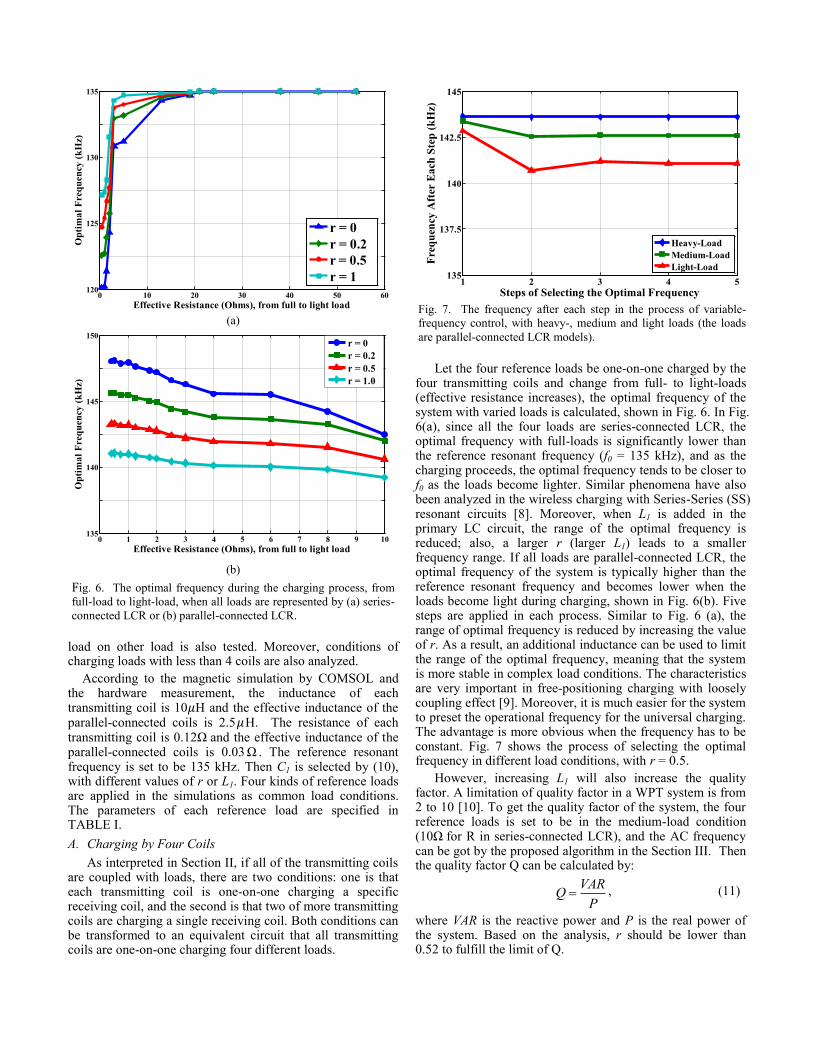
Let the four reference loads be one-on-one charged by the four transmitting coils and change from full- to light-loads (effective resistance increases), the optimal frequency of the system with varied loads is calculated, shown in Fig. 6. In Fig. 6(a), since all the four loads are series-connected LCR, the optimal frequency with full-loads is significantly lower than the reference resonant frequency (f0 = 135 kHz), and as the charging proceeds, the optimal frequency tends to be closer to f0 as the loads become lighter. Similar phenomena have also been analyzed in the wireless charging with Series-Series (SS) resonant circuits [8]. Moreover, when L1 is added in the primary LC circuit, the range of the optimal frequency is reduced; also, a larger r (larger L1) leads to a smaller frequency range. If all loads are parallel-connected LCR, the optimal frequency of the system is typically higher than the reference resonant frequency and becomes lower when the loads become light during charging, shown in Fig. 6(b). Five steps are applied in each process. Similar to Fig. 6 (a), the range of optimal frequency is reduced by increasing the value of r. As a result, an additional inductance can be used to limit the range of the optimal frequency, meaning that the system is more stable in complex load conditions. The characteristics are very important in free-positioning charging with loosely coupling effect [9]. Moreover, it is much easier for the system to preset the operational frequency for the universal charging. The advantage is more obvious when the frequency has to be constant. Fig. 7 shows the process of selecting the optimal frequency in different load conditions, with r = 0.5.
However, increasing L1 will also increase the quality factor. A limitation of quality factor in a WPT system is from 2 to 10 [10]. To get the quality factor of the system, the four reference loads is set to be in the medium-load condition (10 for R in series-connected LCR), and the AC frequency can be got by the proposed algorithm in the Section III. Then the quality factor Q can be calculated by:
VAR
QP
, (11)
where VAR is the reactive power and P is the real power of the system. Based on the analysis, r should be lower than 0.52 to fulfill the limit of Q.
(a)
(b)
Fig. 6. The optimal frequency during the charging process, from
full-load to light-load, when all loads are represented by (a) series-
connected LCR or (b) parallel-connected LCR.
Fig. 7. The frequency after each step in the process of variable-
frequency control, with heavy-, medium and light loads (the loads
are parallel-connected LCR models).
0 10 20 30 40 50 60120
125
130
135
Effective Resistance (Ohms), from full to light load
Op
tim
al
Fre
qu
ency
(k
Hz)
r = 0
r = 0.2
r = 0.5
r = 1
0 1 2 3 4 5 6 7 8 9 10135
140
145
150
Effective Resistance (Ohms), from full to light load
Op
tim
al
Fre
qu
ency
(k
Hz)
r = 0
r = 0.2
r = 0.5
r = 1.0
1 2 3 4 5135
140
145
142.5
137.5
Steps of Selecting the Optimal Frequency
Fre
qu
ency
Aft
er E
ach
Ste
p (
kH
z)
Heavy-Load
Medium-Load
Light-Load
B. Influence of one load on other loads
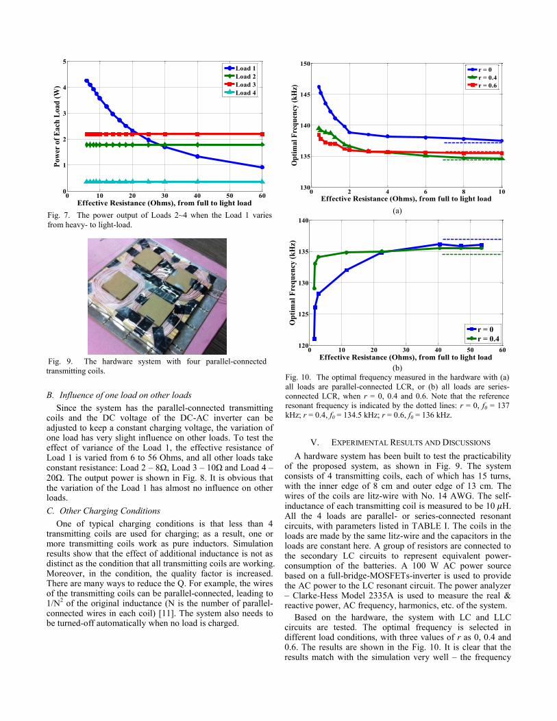
Since the system has the parallel-connected transmitting coils and the DC voltage of the DC-AC inverter can be adjusted to keep a constant charging voltage, the variation of one load has very slight influence on other loads. To test the effect of variance of the Load 1, the effective resistance of Load 1 is varied from 6 to 56 Ohms, and all other loads take constant resistance: Load 2 – 8 , Load 3 – 10 and Load 4 – 20 . The output power is shown in Fig. 8. It is obvious that the variation of the Load 1 has almost no influence on other loads.
C. Other Charging Conditions
One of typical charging conditions is that less than 4 transmitting coils are used for charging; as a result, one or more transmitting coils work as pure inductors. Simulation results show that the effect of additional inductance is not as distinct as the condition that all transmitting coils are working. Moreover, in the condition, the quality factor is increased. There are many ways to reduce the Q. For example, the wires of the transmitting coils can be parallel-connected, leading to 1/N
2 of the original inductance (N is the number of parallel-
connected wires in each coil) [11]. The system also needs to be turned-off automatically when no load is charged.
V. EXPERIMENTAL RESULTS AND DISCUSSIONS
A hardware system has been built to test the practicability of the proposed system, as shown in Fig. 9. The system consists of 4 transmitting coils, each of which has 15 turns, with the inner edge of 8 cm and outer edge of 13 cm. The wires of the coils are litz-wire with No. 14 AWG. The self-inductance of each transmitting coil is measured to be 10 H. All the 4 loads are parallel- or series-connected resonant circuits, with parameters listed in TABLE I. The coils in the loads are made by the same litz-wire and the capacitors in the loads are constant here. A group of resistors are connected to the secondary LC circuits to represent equivalent power-consumption of the batteries. A 100 W AC power source based on a full-bridge-MOSFETs-inverter is used to provide the AC power to the LC resonant circuit. The power analyzer – Clarke-Hess Model 2335A is used to measure the real & reactive power, AC frequency, harmonics, etc. of the system.
Based on the hardware, the system with LC and LLC circuits are tested. The optimal frequency is selected in different load conditions, with three values of r as 0, 0.4 and 0.6. The results are shown in the Fig. 10. It is clear that the results match with the simulation very well – the frequency
Fig. 7. The power output of Loads 2~4 when the Load 1 varies
from heavy- to light-load.
Fig. 9. The hardware system with four parallel-connected
transmitting coils.
(a)
(b)
Fig. 10. The optimal frequency measured in the hardware with (a)
all loads are parallel-connected LCR, or (b) all loads are series-
connected LCR, when r = 0, 0.4 and 0.6. Note that the reference
resonant frequency is indicated by the dotted lines: r = 0, f0 = 137
kHz; r = 0.4, f0 = 134.5 kHz; r = 0.6, f0 = 136 kHz.
0 10 20 30 40 50 600
1
2
3
4
5
Effective Resistance (Ohms), from full to light load
Pow
er o
f E
ach
Load
(W
)
Load 1
Load 2
Load 3
Load 4
0 2 4 6 8 10130
135
140
145
150
Effective Resistance (Ohms), from full to light load
Op
tim
al
Fre
qu
ency
(k
Hz)
r = 0
r = 0.4
r = 0.6
0 10 20 30 40 50 60120
125
130
135
140
Effective Resistance (Ohms), from full to light load
Op
tim
al
Fre
qu
ency
(k
Hz)
r = 0
r = 0.4

range is significantly smaller with higher r. This will lead to a more stable system. When r = 0.6, the quality factor is too high for a practical application. So 0.4 is selected as a more appropriate value for r. In Fig. 9, however, the result shows that during the charging process of an LLC circuit, the optimal frequency will increase or decrease beyond the reference resonant frequency, as r = 0.6 in Fig. 10(a) and r = 0.4 in Fig. 10(b). The two possible reasons include 1) varied resistance in high-frequency condition and 2) unwanted coupling among the transmitting coils or between a transmitting coil and non-corresponding receiving coils.
The efficiency the system with r = 0.4 is measured, which changes with different load conditions, shown in Fig. 11. The efficiency is high enough for the practical applications. However, the efficiency becomes lower when the effective load resistance increases, because larger resistance generates smaller impedance of the load in the primary side and makes the resistance in other parts of the system consumes more percentages of power. It is also possible to further improve the power transfer efficiency using recently developed meta-material [12, 13], and artificial magnetic conductor (AMC) technologies in the WPT system [14].
VI. CONCLUSION
A novel wireless charging system for multiple portable devices is proposed in this paper. Based on LLC resonant circuit and parallel-connected transmitting coils, the system limits the optimum frequency in a much smaller range with a stable charging voltage. A variable-frequency control algorithm is applied to seek the optimal frequency and realize the maximum charging power. With well-designed r, the system keeps a high-efficiency charging in different load conditions while each load has a charging process independent of other loads. Simulations and a hardware prototype are used to test the system. For future research, the control loop will be built by hardware devices to realize accurate control of AC frequency according to different load conditions.
REFERENCE
[1] Available: http://www.wirelesspowerconsortium.com/
[2] W. X. Zhong, X. Liu, and S. Y. R. Hui, "A Novel Single-Layer
Winding Array and Receiver Coil Structure for Contactless Battery
Charging Systems With Free-Positioning and Localized Charging
Features," Industrial Electronics, IEEE Transactions on, vol. 58, pp.
4136-4144, 2011.
[3] J. J. Casanova, L. Zhen Ning, and L. Jenshan, "A Loosely Coupled
Planar Wireless Power System for Multiple Receivers," Industrial
Electronics, IEEE Transactions on, vol. 56, pp. 3060-3068, 2009.
[4] L. Xun and S. Y. R. Hui, "Optimal Design of a Hybrid Winding
Structure for Planar Contactless Battery Charging Platform," Power
Electronics, IEEE Transactions on, vol. 23, pp. 455-463, 2008.
[5] W. Chwei-Sen, O. H. Stielau, and G. A. Covic, "Design considerations
for a contactless electric vehicle battery charger," Industrial Electronics,
IEEE Transactions on, vol. 52, pp. 1308-1314, 2005.
[6] W. Chwei-Sen, G. A. Covic, and O. H. Stielau, "General stability
criterions for zero phase angle controlled loosely coupled inductive
power transfer systems," in Industrial Electronics Society, 2001.
IECON '01. The 27th Annual Conference of the IEEE, 2001, pp. 1049-
1054 vol.2.
[7] W. Yerazunis, B. Wang, and K. H. Teo, "Power delivery optimization
for a mobile power transfer system based on resonator arrays," in
Antennas and Propagation (ISAP), 2012 International Symposium on,
2012, pp. 174-177.
[8] C. Zheng, R. Chen, E. Faraci, Z. U. Zahid, M. Senesky, D. Anderson, et
al., "High efficiency contactless power transfer system for electric
vehicle battery charging," in Energy Conversion Congress and
Exposition (ECCE), 2013 IEEE, 2013, pp. 3243-3249.
[9] K. Kusaka and J. I. Itoh, "Proposal of Switched-mode Matching Circuit
in power supply for wireless power transfer using magnetic resonance
coupling," in Applied Power Electronics Conference and Exposition
(APEC), 2012 Twenty-Seventh Annual IEEE, 2012, pp. 653-660.
[10] O. H. Stielau and G. A. Covic, "Design of loosely coupled inductive
power transfer systems," in Power System Technology, 2000.
Proceedings. PowerCon 2000. International Conference on, 2000, pp.
85-90 vol.1.
[11] G. A. Covic, M. L. G. Kissin, D. Kacprzak, N. Clausen, and H. Hao, "A
bipolar primary pad topology for EV stationary charging and highway
power by inductive coupling," in Energy Conversion Congress and
Exposition (ECCE), 2011 IEEE, 2011, pp. 1832-1838.
[12] B. Wang, W. Yerazunis, and K. H. Teo, "Wireless Power Transfer:
Metamaterials and Array of Coupled Resonators," Proceedings of the
IEEE, vol. 101, pp. 1359-1368, 2013.
[13] B. Wang, K. H. Teo, T. Nishino, W. Yerazunis, J. Barnwell, and J.
Zhang, "Experiments on wireless power transfer with metamaterials,"
Applied Physics Letters, vol. 98, pp. 254101-254101-3, 2011.
[14] J. Wu, B. Wang, W. S. Yerazunis, and K. H. Teo, "Wireless power
transfer with artificial magnetic conductors," in Wireless Power
Transfer (WPT), 2013 IEEE, 2013, pp. 155-158.
Fig. 11. The measured efficiency of the prototype system in different load
conditions.
0 10 20 30 40 50 600
20
40
60
80
100
Effective Resistance (Ohms), from full to light load
Eff
icie
ncy
(%
)