Embed Size (px)
Citation preview

TM 10-3930-633-34
D E P A R T M E N T O F T H E A R M Y T E C H N I C A L M A N U A L
TECHNICAL MANUAL
DIRECT SUPPORT, AND GENERAL SUPPORT
MAINTENANCE MANUAL
TRACTOR, WHEELED, WAREHOUSE GASOLINE,
4-WHEEL PNEUMATIC TIRED,
4000 POUND DRAWBAR PULL
(ARMY MODEL MHE-228)
(CLARK EQUIPMENT MODEL 2330237)
NSN 3930-00-347-6173
H E A D Q U A R T E R S , D E P A R T M E N T O F T H E A R M Y
MARCH 1975
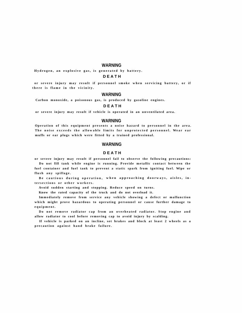
WARNINGHydrogen, an explosive gas, is generated by battery.
D E A T H
or severe injury may result if personnel smoke when servicing battery, or if there is flame in the vicinity.
WARNINGCarbon monoxide, a poisonous gas, is produced by gasoline engines.
D E A T Hor severe injury may result if vehicle is operated in an unventilated area.
WARNINGOperation of this equipment presents a noise hazard to personnel in the area.The noise exceeds the allowable limits for unprotected personnel. Wear earmuffs or ear plugs which were fitted by a trained professional.
WARNING
D E A T Hor severe injury may result if personnel fail to observe the following precautions:
Do not fill tank while engine is running. Provide metallic contact between thefuel container and fuel tank to prevent a static spark from igniting fuel. Wipe orflush any spillage.
Be cautious during operation, when approaching doorways, aisles , in-
tersections or other workers.Avoid sudden starting and stopping. Reduce speed on turns.Know the rated capacity of the truck and do not overload it.Immediately remove from service any vehicle showing a defect or malfunction
which might prove hazardous to operating personnel or cause further damage toequipment.
Do not remove radiator cap from an overheated radiator. Stop engine andallow radiator to cool before removing cap to avoid injury by scalding.
If vehicle is parked on an incline, set brakes and block at least 2 wheels as aprecaution against hand brake failure.

TM 10-3930-633-34C 1
CHANGE
NO. 1
HEADQUARTERSDEPARTMENT OF THE ARMY
Washington D. C., 22 November 1989
DIRECT SUPPORT AND GENERAL SUPPORT MAINTENANCE MANUAL
TRACTOR, WHEELED, WAREHOUSEGASOLINE, 4-WHEEL PNEUMATIC TIRED,
4000 POUND DRAWBAR PULL(ARMY MODEL MHE-228)
(CLARK EQUIPMENT MODEL 2330237)NSN 3930-00-347-6173
TM 10-3930-633-34, 7 March 1975, is changed as follows:
1. Remove old pages and insert new pages.
2. New or changed material is indicated by a vertical bar in the margin of the page and by a vertical baradjacent to the TA number.
Remove Pages Insert Pages
iii and iv iii and iv1-1 and 1-2 1-1 and 1-2
4-3 through 4-6 4-3/(4-4 Blank)6-13 and 6-14 6-13 through 6-146-27 and 6-28 6-27 through 6-28. 1/(6-28. 2 Blank)A-1 and “A-2” A-1/(A-2 Blank)I-1 through I-4 I-1 through I-4
3. File this change sheet in front of the publication for reference purposes.
1

By Order of the Secretary of the Army
Official:
CARL E. VUONOGeneral, United States Army
Chief of Staff
WILLIAM J. MEEHAN IIBrigadier General, United States Army
The Adjutant General
Distribution
To be distributed in accordance with DA Form 12-25F-R (Block Nos 2279 and 2280), Unit, Direct Support and GeneralSupport maintenance requirements for Tractor, Warehouse, 4000 LB DBP, Pneumatic Tire, Gas, Model MHE-228.

T E C H N I C A L M A N U A L
N o . 1 0 - 3 9 3 0 - 6 3 3 - 3 4
D I R E C T
C HAPTER 1.
Section I.
I I .
CHAPTER 2.
Section I.
I I .
I I I .
I V .
Chapter 3.
Section I.
I I .
I I I .
CHAPTER 4.
5 .
6 .
Section I.
I I .
I I I .
I V .
V .
V I .
V I I .
V I I I .
I X .
CHAPTER 7.
Section I.
I I .
111.
C h a p t e r 8 .
Chapter 9.
S e c t i o n I .
I I .
TM 10-3930-633-34
H E A D Q U A R T E R S
D E P A R T M E N T O F T H E A R M YWashington, D. C., 7 March 1975
S U P P O R T A N D G E N E R A L S U P P O R T M A I N T E N A N C E M A N U A L
T R A C T O R , W H E E L E D , W A R E H O U S E
G A S O L I N E , 4 - W H E E L P N E U M A T I C
T I R E D , 4 0 0 0 P O U N D D R A W B A R P U L L
( A R M Y M O D E L
( C L A R K E Q U I P M E N T
M H E - 2 2 8 )
M O D E L 2 3 3 0 2 3 7 )
N S N 3 9 3 0 - 0 0 - 3 4 7 - 6 1 7 3
Paragraph Page
I N T R O D U C T I O N
General . . . . . . . . . . . . . . . . . . . . . . . . . . . . . . . . . . . 1-1
Description and Data . . . . . . . . . . . . . . . . . . . . . . . . . . . . . . . . . . . . . . . . . . . . . . . . . . . . . 1-7
D I R E C T S U P P O R T A N D G E N E R A L S U P P O R T M A I N T E N A N C E I N S T R U C T I O N S
Repair Parts, Special Tools and Equipment . . . . . . . . . . . . . 2-1
Troubleshooting . . . . . . . . . . . . . . . . . . . . . . . . . . . . . . . . . . . . . 2-3
General Maintenance . . . . . . . . . . . . . . . . . . . . . . . . . . . 2-4
Removal and Installation of Major Component and Assemblies . . . . . 2-23
R E P A I R O F E L E C T R I C A L S Y S T E M
Alternator . . . . . . . . . . . . . . . . . . . . . . . . . . . . . . . . . . . 3-1
Starter . . . . . . . . . . . . . . . . . . . . . . . . . . . . . . . . . . . . . . . . . . . . . . . . . . . . . . . . . . . . . . . . . . . . . . 3-5
Ignition Distributor . . . . . . . . . . . . . . . . . . . . . . . 3-7
REPAIR OF FUEL SYSTEM . . . . . . . . . . . . . . . . . . . . . . . . . . . . . . . . . . . . . . . . 4-1
REPAIR OF COOLING SYSTEM . . . . . . . . . . . . . . . . . . . . . . . . . . . . . . . . . . . . . . . . . . 5-1
R E P A I R O F E N G I N E
Description . . . . . . . ... . . . . . . . . . . . . . . . . . . . . . 6-1
EngineTest and Performance Analysis . . . . . . . . . . . . . . .. . .. . . . . . . . . . . . . .. . 6-6
Engine Overhaul . . . . . . . . . . . . . . . . . . . . . 6-9
Cylinder Head and Valves . . . . . . . . . . . . . . . . . . . . . . . . .. . . . .. . . . 6-13
Cylinder Block . . . . . . . . . . . . . . . . . . . . . . . . . . . . . . . . . . . . . . . . . . . . . . . . . . . . . . . . . . . . . . . . . . 6-22
Pistons, Pins and Rings . . . . . . . . . . . . . . . . . . . . . . . .. . . . . . . . . . . 6-26
Connecting Rod and Crankshaft . . . . . . . . . . . .. . . . . . . . . ... . 6-29
Camshaft and Timing Gears . . . . . . . . . . . . . . . . . . . . . . ...6-37
Oil Pan and Oil Pump . . . . . . . . . . . . . . 6-42
R E P A I R O F T R A N S M I S S I O N
Description . . . . . . . . . . . . . . . . . . . . . . . . . . . . . . . . . . . . . . . . . . . . . . . . . . . . . .7-1
Adjustments and Tests . . . . . . . . . . . . . . . . . . . . . . . . . . . . . . .. . . . .. . . . . . . . . . . . .. . . . 7 - 4
T r a n s m i s s i o n R e p a i r s . . . . . . . . . . . . . . . . . . . . . . . . . . . . . . . . . . . . . 7 - 1 0
REPAIR OF PROPELLER SHAFT. . . . . . . . . . . . . . . . .. . . .. . . . . . . . . . . . 8-1
R E P A I R O F W H E E L S A N D B R A K E S
W h e e l s a n d T i r e s . . . . . . . . . . . . . . . . . . . . . . . . . . . . . . 9 - 1
Brake System . . . . . . . . . . . . . . . . . . . 9-5
1 - 1
1 - 1
2 - 1
2 - 1
2 - 7
2 - 1 2
3 - 1
3 - 6
3 - 9
4 - 1
5 - 1
6 - 1
6 - 2
6 - 4
6 - 1 3
6 - 2 1
6 - 2 3
6 - 2 8
6 - 3 6
6 - 4 1
7 - 1
7 - 5
7 - 9
8 - 1
9 - 1
9 - 2
i

TM 10-3930-633-34
C H A P T E R 1 0 .
11.
12.
A P P E N D I X A .
INDEX . . . . . . . . .. . . ...
REPAIR OF REAR AXLE AND SPRINGS . . . . . . . . . . . . .
Paragraph Page
1 0 - 1 1 0 - 1
REPAIR OF STEERING SYSTEM . . . . . . . . . . . . . . . . . . . 11-1 1 1 - 1
REPAIR OF FRONT AXLE AND SPRINGS . . . . . . . . . . . . . . . . . . . . . . . . . ... . . . . 12-1 1 2 - 1
REFERENCES . . . . . . . . . . . . . . . . . . . . . . . . . . . . . . . . . . . . . . . . . . . . . . . . . . . . . . . . . . . . . . . . . . . . . A-1
. . . . . . . . . . . . . . . . . . . . . . . . . . . . . . . . . . . . . . . . . . . . . . . I - 1
i i
TM 10-3930-633-34
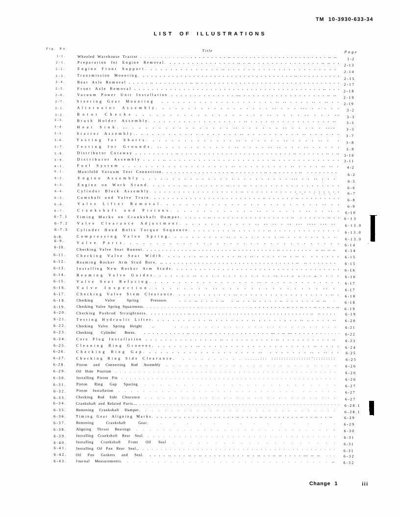
L I S T O F I L L U S T R A T I O N S
F i g . N o .
1 - 1 .
2 - 1 .
2 - 2 .
2 - 3 .
2 - 4 .
2 - 5 .
2 - 6 .
2 - 7 .
3 - 1 .
3 - 2 .
3 - 3 .
3 - 4 .
3 - 5 .
3 - 6 .
3 - 7 .
3 - 8 .
3 - 9 .
4 - 1 .
6 . 1 .
6 - 2 .
6 - 3 .
6 - 4 .
6 - 5 .
6 - 6 .
6 - 7 .
6 - 7 . 1
6 - 7 . 2
6 - 7 . 3
6 - 8 .6 - 9 .
6 -10 .
6 - 1 1 .
6 - 1 2 .
6 - 1 3 .
6 - 1 4 .
6 - 1 5 .
6 - 1 6 .
6 - 1 7 .
6 - 1 8 .
6 - 1 9 .6 - 2 0 .
6 - 2 1 .
6 - 2 2 .
6 - 2 3 .
6 - 2 4 .
6 - 2 5 .
6 - 2 6 .
6 - 2 7 .
6 - 2 8 .
6 - 2 9 .
6 - 3 0 .
6 - 3 1 .
6 - 3 2 .
6 - 3 3 .6 - 3 4 .
6 - 3 5 .
6 - 3 6 .
6 - 3 7 .
6 - 3 8 .
6 - 3 9 .
6 - 4 0 .6 - 4 1 .
6 - 4 2 .
6 - 4 3 .
Tit l e
Wheeled Warehouse Tractor . . . . . . . . . . . . . . . . . . . . . . .. . . . . . . . . . . . . . . . . . . . . . . . .. .. P r e p a r a t i o n f o r E n g i n e R e m o v a l . . . . . . . . . . . . . . . . .. . .. . . . . . . . . . . . . . . . .. .. . .E n g i n e F r o n t S u p p o r t . . . . . . . . . . . . . . . .. . . . . . . . . . . . . . . . . . . . . . . T r a n s m i s s i o n M o u n t i n g . . . . . . . . . . . . . . . . . . . . . . . . . . . . . . . . . . . . . .. . . . . . . . . . .R e a r A x l e R e m o v a l . . . . . .. . . . . . . . . .. .. . . . . . . . . . . . . . . . . . . . . . . . . . . . . . . . . .F r o n t A x l e R e m o v a l . . . . . . . . . . . . . . . . . . . . . . . . . . . . . . . . . . . . . . . . . . .. . . .V a c u u m P o w e r U n i t I n s t a l l a t i o n . . . . . . . . . . . . . . ... . . . . . . . . . . . . . . . . . . .. .. S t e e r i n g G e a r M o u n t i n g . . . . . . . . . . . . . . . . . . . . . .. .. . . . . .. . .. . .A l t e r n a t o r A s s e m b l y . . . . . . . . . . . . . . . . . . . . . . . . . . . . . . .R o t o r C h e c k s . . . . . . . . . . . . . . . . . . . . . . . . . . . . . . . .B r u s h H o l d e r A s s e m b l y . . . . . . . . . . . . . . . . . . . .. . . . . .. . . . . . . . . . . . .. H e a t S i n k . . . . . . . . . . . . . . . . . . . . . . . . . . . . . . . . . . . . . S t a r t e r A s s e m b l y . . . . . . . . . . . . . . . . . . . . .. . . . . . . . . . . .. . . . . . .T e s t i n g f o r S h o r t s . . . . . . . . . . . . . . . . . . . . . . . . . . . . . . . .T e s t i n g f o r G r o u n d s . . . . . . . . . . . . . . . . . . . . . . . . . . . . . . . . . .D i s t r i b u t o r C u t a w a y . . . . . . . . . .. . . . . . . . . . . . . . . . . . . . . . . . . . .. . . . . . . .. . ..D i s t r i b u t o r A s s e m b l y . . . . .. . . . . . . . . . . . . . . . . . . . . . .. . . . . . . . . . . . . .F u e l S y s t e m . . . . . . . . . . . . . . . . . . . . . . . . . . . . . . . . . . . . . . . . .M a n i f o l d V a c u u m T e s t C o n n e c t i o n . . . . . . . . . . . . . . . . . .. . . . . . . . .. . .. . . . . . .. . . . . . . . . E n g i n e A s s e m b l y . . . . . . . . . . . . . . . . . . . . . . . . . . . . . . . . . . . E n g i n e o n W o r k S t a n d . . . . . . . .. . . . . . . . .. . . .. . . . . . . . . . . . . . . . . . .
.
C y l i n d e r B l o c k A s s e m b l y . . . . . . . . . . . . . . . . . . . .. . . . . . . . . . . . . . . . . . . . .C a m s h a f t a n d V a l v e T r a i n . . . . . . . . . . . . . . . . . . . . . . . . . .. . . . . . . .. . . . . . . . . .
. , . . . , .
V a l v e L i f t e r R e m o v a l . . . . . . . . . . . . . . . . . . . . . . . . . . . . .C r a n k s h a f t a n d P i s t o n s . . . . . . . . . . . . . . . . . . . . . . . . . . . .T i m i n g M a r k s o n C r a n k s h a f t D a m p e r . . . . . . .. . . . . . . . . . . . . . . . . . .. . . . . . . .. . .V a l v e C l e a r a n c e A d j u s t m e n t . . . . . . . . . . . . . . . . . . . . . . . . . . . . . . . . . C y l i n d e r H e a d B o l t s T o r q u e S e q u e n c e . . . . . . . . . .. . . . . . . .. . . . . . . . . . . . . . .C o m p r e s s i n g V a l v e S p r i n g . . . . . . . . . . . . . . . . . . . . . . . . . . . . . . . V a l v e P a r t s . . . . . . . . . . . . . . . . . . . . . . . . . . . . . . . . .Checking Valve Seat Runout . . . . . . . . . . . . . .. . . . . . . . . . .. . . . . . . . . . . .. . . . . . . . . .. ... .. ..C h e c k i n g V a l v e S e a t W i d t h . . . . . . . .. . . . . . . .. . .. . . . . . .. . .. . . . . . . .R e a m i n g R o c k e r A r m S t u d B o r e . .. . . . . . . . . . . . . . . . . . . . . . . . . . . . . . . . . .. .. . . . . . . .I n s t a l l i n g N e w R o c k e r A r m S t u d s . . . . . . . . . . . . . . . . . . . . . . . . . . . . . . . . . . . . .R e a m i n g V a l v e G u i d e s . . . . . . . . . . . . . . . . . . . . . . . . . . . . . . . . . . . . . . . . ...
V a l v e S e a t R e f a c i n g . . . . . . . . . . . . . . . . . . . . . . . . . . . . . . . . .V a l v e I n s p e c t i o n . . . . . . . . . . . . . . . . . . . . . . . . . . . . .C h e c k i n g V a l v e S t e m C l e a r a n c e . . . . . . . . . . . . .. . . . . . . . . . . . . . . . . . . .. .Checking Valve Spring Pressure. . . . .. . . . . .. . .. . . .. . . . . .. . . . . . . .. .. .
Checking Valve Spring Squareness. . . . . . . . . . . . . . . .. . . . . . . . . . .. . . . .. . . . . . . . . .. . . .. . . .. . . .. . ..Checking Pushrod Straightness. . . . . . . . . . . .. . . . . . . . . . . . . . . . . . . . . . . . . . . . . . . . . .. .. . . . .T e s t i n g H y d r a u l i c L i f t e r . . . . . . . . . . . .. . . . . . . . .. . . . . . . . . .. . . . . . .. . . .
Checking Valve Spring Height .. . . . . . . . . . . . . . . . . . . . . . . . . . . .
Checking Cylinder Bores. . . . . . . . . . . .. . . . . .. . . . . . . . . . . . . . ... . .. ... . . . . . . . . . . . .
C o r e P l u g I n s t a l l a t i o n . . . . . . . . . . . . . . . .. . . . . . . . . . . .. . . . . . . . . . . ..C l e a n i n g R i n g G r o o v e s . . . . . . . . .. . . . . . . . . . . . . . . . . . . . . .. . . . .C h e c k i n g R i n g G a p . . . . . . . . . . . . . . . . . . . . . . . . . . . . . . . . . . . .C h e c k i n g R i n g S i d e C l e a r a n c e . . . . . . . . . . . . . . . . . : : : : : : : : : : : : : : : : : : : ’ : : : : : : : : :
Piston and Connecting Rod Assembly . . . . . . . . . . . . . . . . . . . . . . . . . .
Oil Hole Position . . . . . . . . . . . . . . . . . . . . . . . . . . . . . . . . . . . . . . . . . . . . . . .
Installing Piston Pin . . . . . . . . . . . . . . . . . . . . . . . . . . . . . . . . . . . . . . . . . . . . . . . . .
Piston Ring Gap Spacing . . . . . . . . . . . . . . . . . . . . . . . . .
Piston Installation . . . . . . . . . . . . . . . . . . . . . . . . . . . . . . . . . . .
Checking Rod Side Clearance . . . . . . . . . . . . . . . . . . . . . . . . . . . . . . . .
Crankshaft and Related Parts.... . . . . . . . . . . . . . . . . . . . . . . . . . . . . . . . . . . . . . . . . . . . . . . . . . . . . . . . . . . .
Removing Crankshaft Damper. . . . . . . . . . . . . . . . . . . . . . . . . . . . . . .
T i m i n g G e a r A l i g n i n g M a r k s . . . . . .. . . . . . . . . . . . . . .. . . . . .. . . . . . . . . .. . . .. . . .. Removing Crankshaft Gear. . . . . . . . . . . . . . .
Aligning Thrust Bearings . . . . . . . . . . . . . . . . . . . . . . . . . . . . . ..
Installing Crankshaft Rear Seal. . . . . . . . . . . . . . . . . . . . . . . . . . . . . . . . . . . . .
Installing Crankshaft Front Oil Seal . . . . . . . . . . . . . . . . . . . .
Installing Oil Pan Rear Seal... . . . . . . . . . . . . . . . . . . . . . . . . . . . . . . . . . . . . . . . . . . .
Oil Pan Gaskets and Seal. . . . . .. . . . .. . .. . . . . . . . . . .. . .. . . .. .. . . . . ... .. .. . . .
Journal Measurements. . . . . . . . . . . . . . . . . . . . . . . . . . . . . . . . . . ,,.
P a g e
1 - 2
2 - 1 3
2 - 1 4
2 - 1 5
2 - 1 7
2 - 1 8
2 - 1 9
2 - 1 9
3 - 2
3 - 3
3 - 5
3 - 5
3 - 7
3 - 8
3 - 9
3 - 1 03 - 1 1
4 - 2
6 - 2
6 - 5
6 - 66 - 7
6 - 8
6 - 9
6 - 1 0
6 - 1 3
6 - 1 3 . 0
6 - 1 3 . 0
6 - 1 3 . 0
6 - 1 46 - 1 4
6 - 1 5
6 - 1 5
6 - 1 6
6 - 1 6
6 - 1 7
6 - 1 7
6 - 1 8
6 - 1 8
6 - 1 96 - 1 9
6 - 2 0
6 - 2 1
6 - 2 2
6 - 2 3
6 - 2 46 - 2 5
6 - 2 5
6 - 2 6
6 - 2 6
6 - 2 6
6 - 2 7
6 - 2 7
6 - 2 7
6 - 2 8 . 1
6 - 2 8 . 1
6 - 2 9
6 - 2 9
6 - 3 0
6 - 3 1
6 - 3 1
6 - 3 16 - 3 2
6 - 3 2
Change 1 i i i

TM 10-3930-633-34
L I S T O F l L L U S T R A T I O N S - C o n t i n u e d
Fig. No.6-44.6-45.6-46.6-47.6-48.6-49.6-50.6-51.6-52.6-53.6-54.6-55.6-56.6-57.6-58.6-59.6-60.7-1.7-2.7-3.7-4.7-5.7-6.7-7.7-8.7-9.7-10.7-11.7-12.7-13.7-14.7-15.7-16.7-17.7-18.7-19.7-20.7-21.7-22.7-23.7-24.7-25.7-26.7-27.7-28.7-29.7-30.7-31.7-32.7-33.7-34.7-35.8-1.9-1.9-2.9-3.9-4.9-5.9-6.9-7.9-8.9-9.9-10.10-1.10-2.
Title PageTypical Bearing Failures. . . . . . . . . . . . . . . . . . . . . . . . . . . . . . . . . . . .. . . . . . .. . 6-33
Fitting Bearings with Plastigage. . . . . . . . . .. . . . . .. . . .. . . .. . . . . . . .. . . . . . . . . . . 6-34Checking Crankshaft End Play. . . . . . . . . . . . .. . . . . . .. . .. . . . . .. . .. .. . .. .. . .. . .. .. 6-34Aligning Cylinder Front Cover. . . . . . . . . . . . . . . . . . . . . . . . . . . . . . . . . . . . . . . . . . . . . . . . . . .6-35Installing Crankshaft Damper. . . . . . . . . . . . . . . . . . . . . . . . . . . . . . . . . . . . . . . . . . . . . . . . . . . . . . . . .. . . . 6-36Camshaft and Related Parts. . . . . . . . . . . . . . . . . . . . . . . . . . . . . . . . . . . . . . . . . .. 6-36Checking Camshaft End Play. . . . . . . . . . . . . . . . . . . . . . .. . . .. . . . . . . . . . . . . . . . . . . . . . . 6-37Checking Timing Gear Backlash. . . . . . . . . . . . . . . . . . . . . . . . . . . .. . . . . . .. . . . . .. . . . .. . . . .. .. 6-37Checking Timing Gear Runout. .. . . . . . . . . . . .. . . . . . . . . .. . . .. . . . . . .. . . .. ... .. .. .. 6-38Thrust Pla te Screws. . . . . . . . . . . . . . . . . . . . . . . . . . . . . . . . . . . . 6-38Removing Camshaft Gear. . . . . . .. . . . . . .. .. . . . . . . .. . . . . .. . . . . . . . .. . . . .. . . . . 6-38Installing Camshaft Gear. . . . . . . . . . . .. . . . . . . . . . . . . . . . . . .. . . .. . .. . . .. . 6-39Checking Camshaft Lobe Life. . . . . . . . . . . . . . . . . . . . . . .. .. . . . . . .. . . . . . . . . . .. . . . .. . .. . . . 5-40O i l P u m p I n s t a l l e d . . . . . . . . . . . . . . . . . . . . . . . . . . . . . . . . . . . . . 6-41Oil Pump Disassembled. . . . . . . . . . . . . . . . . . . . . . . . . . . . . . . . . . . . . . 6-41Measuring Outer Race Clearance. . .. . . . . . . . . .. . . . . . . . . . . . . . . . . . . . 6-42M e a s u r i n g R o t o r E n d P l a y . . . . . . . . . . . . . . . . . . . . . . . . . . . . . . . 6-42T r a n s m i s s i o n C u t a w a y . . . . . . . . . . . . . . . . . . . . . . . . . . . . . . . . . . . 7-1Hydraulic Control System. . . . . . . . . . . . . . . . . . . . . . . . . . . . . . . . . . . . . 7-3F r o n t B a n d A d j u s t m e n t . . . . . . . . . . . . . . . . . . . . . . . . . . . . . . . . 7-5Rear Band Adjustment . ... . . . . . . . . . . . . . . . . . . . . . . . . . . . . . . . . 7-6Control Pressure Port... . .. . . . . . . . . . . . . . . . . . . . . . . . . . . . . . . . . . . . . 7-7Air Pressure Checks. . . . . . . . . . . . . . . .. .. . . . . . . . .. . . . . . . . . .. . .Transmission Assembly . . . . . . . . . . . . . . . . . . . . . . . . . . . . . . . . . . . . . . . . .. . . .
7-87-10
Extension Housing Par ts . . . . . . . . . . . . . . . . . . . . . . . . . . . . . . . 7-12Output Shaft and Rear Pump.. .. . . . . . . . . . . . . . . . . . . . . . . . . . . . . . . . . 7-13I n p u t S h a f t a n d C l u t c h . . . . . . . . . . . . . . . . . . . . . . . . . . . . 7-13I n p u t S h a f t a n d C l u t c h R e m o v a l . . . . . . . . . . . . . . . . . . . . . . . . . . . . . . . . . . . 7-13Planetary Clutch, Carrier and Center Support .. .. . . . . . . . . . . . . .. . . . . . . .. .......... 7-14P l a n e t a r y C l u t c h I n s t a l l a t i o n . . . . . . . . . . . . . . . . . . . . . . . 7-15C o n t r o l V a l v e B o d y I n s t a l l e d . . . . . . . . . . . . . . . . . . . . . . . . . . . 7-16C o n t r o l V a l v e B o d y . . . . . . . . . . . . . . . . . . . . . 7-18C h e c k V a l v e L o c a t i o n s . . . . . . . . . . . . . . . . . . . . . . . . . 7-19Front Servo. . . . . . . . . . . . . . . . . . . .. . . . . . 7-20Rear Servo. . . . . . . . . . . . . . . .. . . .. . .. . .... . . . .. . . . . . . 7-22E x t e n s i o n H o u s i n g B e a r i n g R e m o v a l . . . . . . . . . . . . . . . . . . . . . . 7-23Installing Extension Housing Seal.. . . . . . . . . . . . . . . . . . . . . . .. . .. . 7-23Governor Installed. . . . . . . . . . . . . . . . .. . . . . .. . 7-23Governor Parts . . . . . . . 7-24P r e s s u r e R e g u l a t o r P a r t s . . . . . . . . . . . . . . . . . . . . . . . 7 - 2 4Manual Linkage. . . . . . . . . . . .. . . . ... . . . . . . . . . . . 7-25Front Pump. . . . . . . . . . . . .. . . . . . . . . . . .. . . . . . .. . . 7-26Removing Front Pump Seal. . . . . . . . . . . . . . . . . . . . . . . . . . . . . . . . . . . 7-26Installing Front Pump Seal. . . . . . . . . .. . . . . . . . . . . . . . . . . . . .. . . 7-27Removing Snap Ring.. . . . . . . . . . . . . . . . . . . . . .. . . .. . 7-27Removing Front Clutch Snapping.. . . . . . . . . . . . . . . . . . . .. .. .. . . . . . . 7-28Removing Piston... . . . . . . . . .. .. . . . . . .. . . . .. . . . . . . . 7-29Clutch Piston Check Ball . . . . . . .. . . . . . . . . . . . . .. . . . . .. . . 7-29Installing Front Clutch Hub . . . . . . .. . . . . .. . . . .. . . . . . . . . . . . . .. . 7-30Installing Pressure Plate . . . . . . . . . . 7-31Installing Clutch Plates . . . . . . . . . . . 7-31Primary Sun Gear Shaft . . . . . . ...’.... . 7-32Propeller Shaft Assembly. . . . . . . . . . . . . . . . . . . . . . . .. . . . . 8-2Wheel Removal. . . . . . . . . . . . . . .. . . . . .. . . .. .. . . . . 9-2Front Brake Assembly . . . . . . . . . . . 9-3Rear Brake Assembly . . . . . . . . . . . . . 9-4Vacuum Power Unit. . . . . . . . . . . . . . . . . . . . . . . . . . . . . . . . 9-6Vacuum Power Unit Cross Section. . . . . . . . . . . . . . . . . .. . .. . . . . . 9-7Vacuum Power Unit Exploded View. . . . . .. . . . . . . . .. . . . . . .. . . .. . . . 9-8Removing Valve Rod. . . . . . . . . . . . .. . . . . . . . .. . . . . . .. . .. . . . . 9-9Separating Front and Rear Shells . . . . . . . . . . . . . . . . . . . . . . . . 9-10Installing Vacuum Seal. . . . . . . . . . . . . .. . . . . . . . .. . . . . . .. . . . . 9-11Adjusting Pushrod. . . . . . . . . .. . . . . . .. .. . . .. .. . . . . . . 9-12Rear Axle Assembly . . . . . . . . . . . . 10-1Loosening Axle Shaft Flange . . . . . . . . . . . . . . . . . . . . . . . . . . . . . . . . . . 10-2
iv

T M 1 0 - 3 9 3 0 - 6 3 3 - 3 4
Fig. No.
10-3.10-4.10-5.10-6.10-7.10-8.10-9.10-10.11-1.11-2.11-3.11-4.12-1.12-2.
Table No.2-1.6-1.6-2.6-3.6-4.6-5.6-6.6-7.7-1.7-2.7-3.
LIST OF
Removing Axle ShaftRemoving Hub and Drum AssemblyDrop Gear CaseDifferential Carrier AssemblyM a t c h M a r k i n gDifferential RemovalDifferential Bearing RemovalInstalling Differential Bearing CapsSteering SystemTie Rod AdjustmentSteer ing Gear and ColumnLash Adjuster ClearanceF r o n t A x l e I n s t a l l a t i o nF r o n t A x l e A s s e m b l y
ILLUSTRATIONS—Continued
Title
L I S T O F T A B L E S
TitleT r o u b l e s h o o t i n g . . . . . . . . . . . . . . . . . . . . . . . . . . . . . . . Manifold Vacuum Readings .. . . . . . . . . . . . . . .. . . . . . . . . . . . . . .. . .. . .. . . . . .. .. .Compression Test Pressure Limits. . . . . . . . . . . . . . . . . .. . . . . . . . . . .. . Engine Fasteners Torque Values . . . . . . . . . . . . . . . . . . . . . . . . . . . . . .Valve Spring Specifications . . . . . . . . . .. . . . . .. . . . . . . . ... . ... ........ . . . . . . ..Piston, Pin, and Ring Fits. . . . . . . . . . . . . . . . . . . . . . . . . . . . . . . . . . . . . . . . . . . . . .Crankshaft, Connecting Rod, and Bearing Specifications . . . . . . . . . . . . . . . . . .. ...........Camshaft and Timing Gear Specifications .. . . . . . . . . . . .... . . . .. . . . . . . . . . . . . . . . . . . . . . .C l u t c h A p p l i c a t i o n s . . . . . . . . . . . . . . . . . . . . . . . . . . . . . . . . .C o n t r o l P r e s s u r e C h e c k s . . . . . . . . . . . . . . . . . . . . . . . . . . . . . . . . .Abnormal Pressure Reading Diagnosis. .... ... . . . . .. . . . . . . . . . . . . . . . . . . .. ... . . .
Page
10-210-210-310-510-610-610-610-711-111-211-311-412-112-2
Page2-16-36-3
6-116-196-246-306-377-27-77-7
V


TM 10-3930-633-34
CHAPTER 1
INTRODUCTION
Section I. GENERAL
1-1. Scope
This manual is for use by direct support andgeneral support maintenance personnel, inm a i n t a i n i n g t h e A r m y M o d e l M H E - 2 2 8Warehouse Tractor.
1-2. Maintenance Forms, Records, and ReportsMaintenance forms, records, and reports which
are to be used by maintenance personnel at allmaintenance levels are listed in and prescribed byDA PAM 738-750.1-3. Reporting Errors and Recommending Im-
provements
You can help improve this manual. If you find anymistakes or if-you- know of a way to improve theprocedures,Form 2028
please let us know. Mail your letter, DA(Recommended Changes to Publications
and Blank Forms), or DA Form 2028-2, located inthe back of this manual, direct to: Commander,U.S. Army Tank-Automotive Command, ATTN:AMSTA-MB, Warren, MI 48397-5000. A reply willbe furnished to you.1-4. Equipment Serviceability Criteria (ESC)
This equipment is not covered by an ESC.
1-5. Destruction of Army Materiel to PreventEnemy Use
Refer to TM 750-244-6 for procedures coveringdestruction of this vehicle to prevent enemy use.
1.6. Administrative Storage
Preparation, care, and removal of equipment inadministrative storage will be in accordance withthe applicable requirements of TM 740-90-1(Administrative Storage of Equipment).
Section Il. DESCRIPTION AND DATA
1-7. Description operations, for towing trailers and other wheeled
a. The wheeled warehouse tractor, shown in loads. A pintle hook is provided at the rear of the
figure 1-1, is designed for use in warehousing vehicle for the attachment of the load.
Change 1 1-1

TM 10-3930-633-34
TA501869
Figure 1-1. Wheeled Warehouse Tractor.
b . T h e t r a c t o r i s d e s i g n e d f o r h i g h gasoline engine, two speed automatic trans-maneuverability and ease o f ope ra t ion in mission, pneumatic tires, and hydraulic, powerwarehousing and transfer operations. The vehicle boosted brakes. The maintenance paragraphs ofis built in accordance with conventional design for this manual contain detailed descriptions of allautomotive-type vehicle, and is equipped with a components.
1-2 Change 1
TM 10-3930-633-34
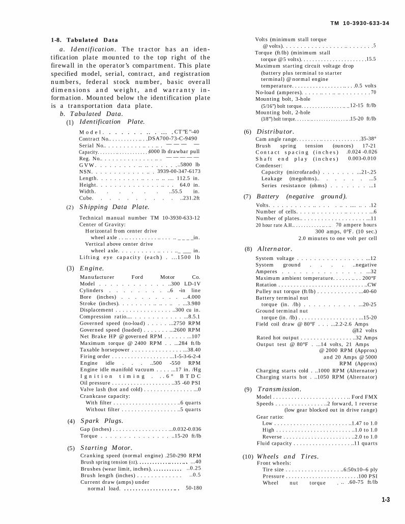
1-8. Tabulated Data
a. Identification. The tractor has an iden-tification plate mounted to the top right of thefirewall in the operator’s compartment. This platespecified model, serial, contract, and registrationnumbers, federal stock number, basic overalldimensions and weight, and warranty in-formation. Mounted below the identification plateis a transportation data plate.
b. Tabulated Data.(1)
(2)
(3)
(4)
(5)
Identification Plate.
M o d e l . . . . . . . .. . ... . CT’’E’’-40Contract No.. . . . . . . . . . .. . ..DSA700-73-C-9490Serial No.. . . . . . . . . . .. . . .. . — — — —Capacity. . . . . . . .. . . . . . . . . . . . .4000 lb drawbar pullReg. No.. . . . . . . . . . . . . . .. . — — — — —
G V W . . . . . . . . . .. .. . . . . . ...5800 lbNSN. . . . . . . . . . . . .. . 3939-00-347-6173Length. . . . . . . . . . .. . . .. .. .... 112.5 in.Height. . . . . . . . . . . . . . .. . . 64.0 in.Width. . . . . . ..55.5 in.Cube. . . . . . . . . . ..231.2ft
Shipping Data Plate.
Technical manual number TM 10-3930-633-12Center of Gravity:
Horizontal from center drivewheel axle . . .. . . . . . . . . . .. . . . .. _ _ _ _in.
Vertical above center drivewheel axle. . . . . . . . . . .. . . . .._ ___ in.
Lifting eye capacity (each) . . . .1500 lb
Engine.Manufacturer Ford Motor Co.Model . . . . . . . . . . . . ..300 LD-1VCylinders . . . . . . . . ..6 -in lineBore (inches) . . . . . . . . . ...4.000Stroke (inches). . . . . . . . .. .. . .. . ...3.980Displacement . . . . . . . . . . . . . . . . ..300 cu in.Compression ratio.... . . . . . . . . . . . ...8.5.1Governed speed (no-load) . . . . . ...2750 RPMGoverned speed (loaded) . . . . . . . ...2600 RPMNet Brake HP @ governed RPM . . . . . . ...107Maximum torque @ 2400 RPM . . ...284 ft/lbTaxable horsepower . . . . . . . . . . . . . . . ...38.40Firing order . . . . . . . . . . . . . . . . . . ...1-5-3-6-2-4Engine idle . . . ..500 -550 RPMEngine idle manifold vacuum . . . . ...17 in. /HgI g n i t i o n t i m i n g . . . 6 ° B T D COil pressure . . . . . . . . . . . . . . . . . . . ..35 -60 PSIValve lash (hot and cold) . . . . . . . . . . . . . . . ...0Crankcase capacity:
With filter . . . . . . . . . . . . . . . . . . . . ..6 quartsWithout filter . . . . . . . . . . . . . . . . . ..5 quarts
Spark Plugs.Gap (inches) . . . . . . . . . . . . . . . . . ...0.032-0.036Torque . . . . . . . . . . . . . . . ..15-20 ft/lb
Starting Motor.Cranking speed (normal engine) .250-290 RPMBrush spring tension (OZ). . . . . . . . . . . . .. . . . . .. .Brushes (wear limit, inches). . . . . . . . . . . .Brush length (inches) . . . . . . . . . . . . .Current draw (amps) under
normal load. . . . . . . . . . . . . . . . . . .. .
. ...40..0.25..0.5
50-180
(6)
(7)
(8)
(9)
Volts (minimum stall torque@ volts). . . . . . . . . . . . . . . . . .. . . . . . . .5
Torque (ft/lb) (minimum stalltorque @ 5 volts). . . . . . . . . . . . . . . . . . . . . . .15.5
Maximum starting circuit voltage drop(battery plus terminal to starterterminal) @ normal enginetemperature. . . . . . . . . . . . . . . . . .. . . .0.5 volts
No-load (amperes). . . . . .. . . .. .. . . . . . . . . 70Mounting bolt, 3-hole
(5/16”) bolt torque. . . . . . . . . . . . . . . .. ..12-15 ft/lbMounting bolt, 2-hole
(3/8”’) bolt torque. . . . . .. .. . . . . . . . . . . . . . .. .15-20 ft/lb
Distributor.Cam angle range. . . . . . . . .. . . . . . . . . . . . . . .35-38°Brush spring tension (ounces) 17-21C o n t a c t s p a c i n g ( i n c h e s ) .0.024 -0.026S h a f t e n d p l a y ( i n c h e s ) 0.003-0.010Condenser:
Capacity (microfarads) . . . . . . . ...21-.25Leakage (megohms).. . . . . . ...5Series resistance (ohms) . . . . . . . ...1
Battery (negative ground).Volts. . . . . . . . . . .. . . . . .. . .... .. . .12Number of cells. . . . .. . . . . . . . .. . . . . . ...6Number of plates.. . . . . . . . . . . . . . . . . . . ...1120 hour rate A.H.. . . . . . . . . . . .. . .. 70 ampere hours
300 amps, 0°F. (10 sec.)2.0 minutes to one volt per cell
Alternator.System voltage . . . . . . . . . . . . . . . . ...12System ground . . . . ..negativeAmperes . . . . . . . . . . . . . . ...32Maximum ambient temperature. . . . . . .. . . 200°FRotation . . . . . . . . . . . . . . . . . . . . . . . . . . . . ..CWPulley nut torque (ft/lb) . . . . . . . . . . . . ...40-60Battery terminal nut
torque (in. /lb) . . . . . . . . . . . ...20-25Ground terminal nut
torque (in. /lb) . . . . . . . . . . . . . . . . . . . ...15-20Field coil draw @ 80°F . . . ...2.2-2.6 Amps
@12 voltsRated hot output . . . . . . . . . . . . . . . . ..32 AmpsOutput test @ 80°F . ...14 volts, 21 Amps
@ 2000 RPM (Approx)and 20 Amps @ 5000
RPM (Approx)Charging starts cold . ..1000 RPM (Alternator)Charging starts hot . ..1050 RPM (Alternator)
Transmission.Model . . . . . . . . . . . . . . . . . . . . . . . . .. Ford FMXSpeeds . . . . . . . . . . . . . . . ..2 forward, 1 reverse
(low gear blocked out in drive range)Gear ratio:
Low . . . . . . . . . . . . . . . . . . . . . . . ..1.47 to 1.0High . . . . . . . . . . . . . . . . . . . . . . . . ..1.0 to 1.0Reverse . . . . . . . . . . . . . . . . . . . . . . ..2.0 to 1.0
Fluid capacity . . . . . . . . . . . . . . . . . . ..11 quarts
(10) Wheels and Tires.Front wheels:
Tire size . . . . . . . . . . . . . . . . . ..6:50x10–6 plyPressure . . . . . . . . . . . . . . . . . . . . . . . . .100 PSIWheel nut torque . .. .60-75 ft/lb
1-3
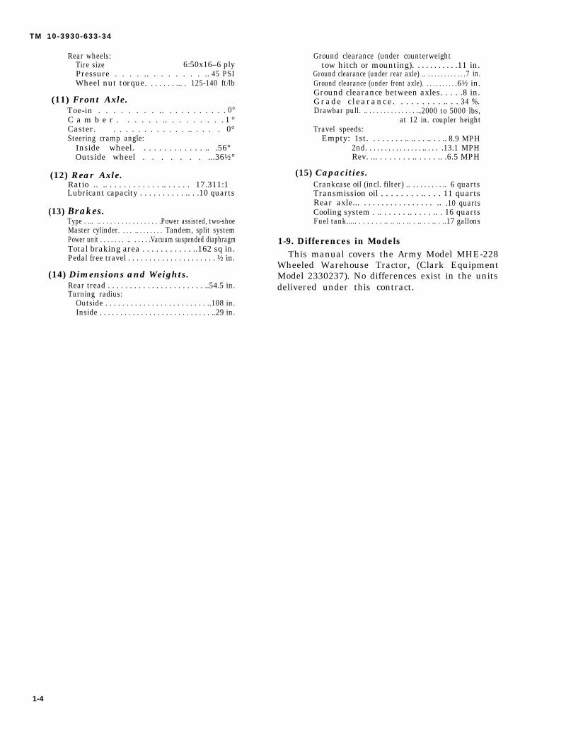
TM 10-3930-633-34
Rear wheels:Tire size 6:50x16–6 plyPressure . . . . .. . . . . . . . .. 45 PSIWheel nut torque. . . . . . . ... . 125-140 ft/lb
(11) Front Axle.Toe-in . . . . . . . . .. . . . . . . . . . . 0°C a m b e r . . . . . . .. . . . . . . . . 1 °Caster. . . . . . . . . . . . . .. . . . . 0°Steering cramp angle:
Inside wheel. . . . . . . . . . . . . .. .56°Outside wheel . . . . . . . ...36½°
(12) Rear Axle.Ratio .. .. . . . . . . . . . . . .. . . . . . 17.311:1Lubricant capacity . . . . . . . . . . .. . .10 quarts
(13) Brakes.Type . ... .. . . . . . . . . . . . . . . . .Power assisted, two-shoeMaster cylinder. . . . .. . . . . . . . Tandem, split systemPower unit . . . . . . . .. . . . . .Vacuum suspended diaphragmTotal braking area . . . . . . . . . . . ..162 sq in.Pedal free travel . . . . . . . . . . . . . . . . . . . . . ½ in.
(14) Dimensions and Weights.Rear tread . . . . . . . . . . . . . . . . . . . . . . ..54.5 in.Turning radius:
Outside . . . . . . . . . . . . . . . . . . . . . . . . ..108 in.Inside . . . . . . . . . . . . . . . . . . . . . . . . . . . ..29 in.
Ground clearance (under counterweighttow hitch or mounting). . . . . . . . . . .11 in.
Ground clearance (under rear axle) .. . . . . . . . . . . . .7 in.Ground clearance (under front axle). . . . . . . . . . .6½ in.Ground clearance between axles. . . . .8 in.Grade c learance. . . . . . . . . .. . . 34 %.Drawbar pull. .. . . . . . . . . . . . . . ...2000 to 5000 lbs,
at 12 in. coupler heightTravel speeds:
Empty: 1st. . . . . . . . .. .. . . .. . . .. 8.9 MPH2nd. . . . . . . . . . . . . . . .. . . . .13.1 MPHRev. ... . . . . . . . .. . . . . .. .6.5 MPH
(15) Capacities.Crankcase oil (incl. filter) .. . . . . . . . . .. 6 quartsTransmission oil . . . . . . . . .. . . . 11 quartsRear axle... . . . . . . . . . . . . . . . . .. .10 quartsCooling system . .. . . . . . .. . . . . .. . 16 quartsFuel tank..... . . . . . . .. .. .. . .. . .. . . .. . ..17 gallons
1-9. Differences in ModelsThis manual covers the Army Model MHE-228
Wheeled Warehouse Tractor, (Clark EquipmentModel 2330237). No differences exist in the unitsdelivered under this contract.
1-4
TM 10-3930-633-34
CHAPTER 2
DIRECT SUPPORT AND GENERAL SUPPORT
MAINTENANCE INSTRUCTIONS
Section I. REPAIR PARTS, SPECIAL TOOLS AND EQUIPMENT
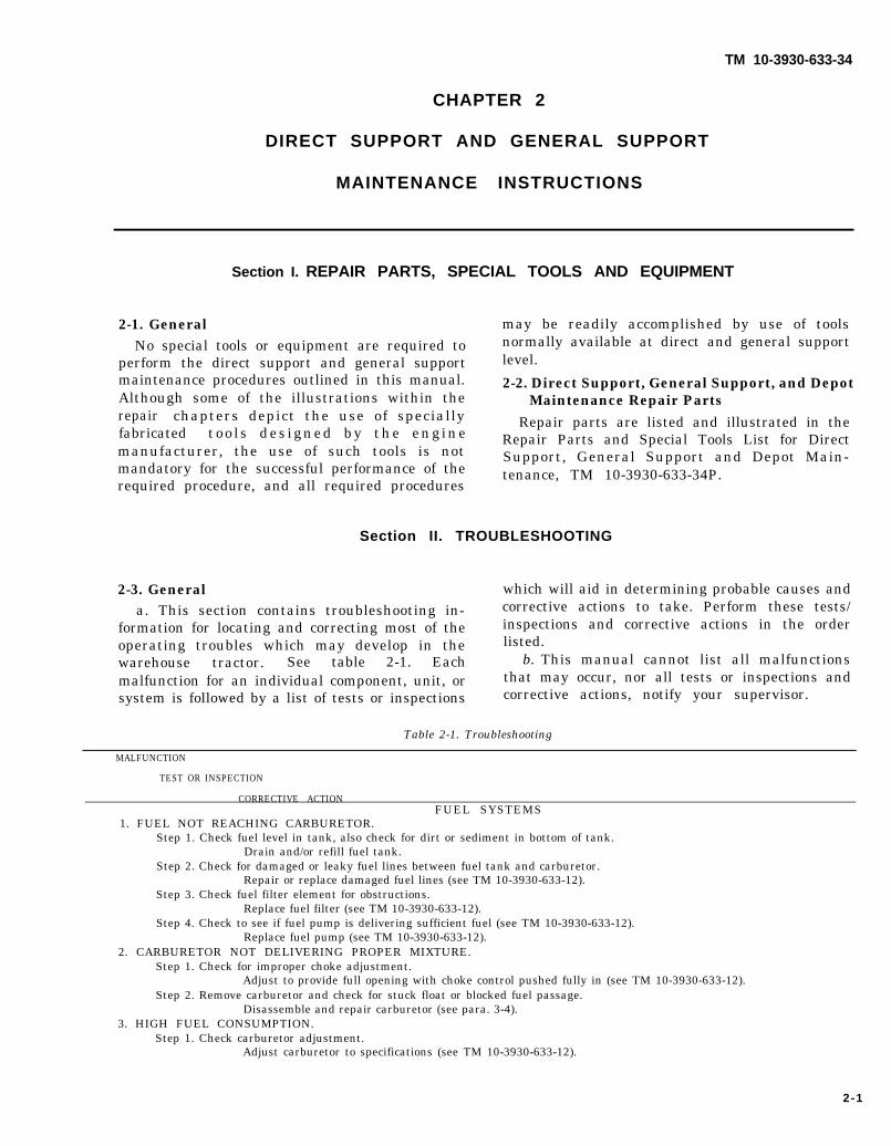
2-1. GeneralNo special tools or equipment are required to
perform the direct support and general supportmaintenance procedures outlined in this manual.Although some of the illustrations within therepair chapters depict the use of speciallyfabricated too ls des igned by the enginemanufacturer, the use of such tools is notmandatory for the successful performance of therequired procedure, and all required procedures
may be readily accomplished by use of toolsnormally available at direct and general supportlevel.
2-2. Direct Support, General Support, and DepotMaintenance Repair Parts
Repair parts are listed and illustrated in theRepair Parts and Special Tools List for DirectSupport, General Support and Depot Main-tenance, TM 10-3930-633-34P.
Section II. TROUBLESHOOTING
2-3. General which will aid in determining probable causes anda. This section contains troubleshooting in- corrective actions to take. Perform these tests/
formation for locating and correcting most of the inspections and corrective actions in the orderoperating troubles which may develop in the listed.warehouse tractor. See table 2-1. Each b. This manual cannot list all malfunctionsmalfunction for an individual component, unit, or that may occur, nor all tests or inspections andsystem is followed by a list of tests or inspections corrective actions, notify your supervisor.
Table 2-1. Troubleshooting
MALFUNCTION
TEST OR INSPECTION
CORRECTIVE ACTIONFUEL SYSTEMS
1. FUEL NOT REACHING CARBURETOR.Step 1. Check fuel level in tank, also check for dirt or sediment in bottom of tank.
Drain and/or refill fuel tank.Step 2. Check for damaged or leaky fuel lines between fuel tank and carburetor.
Repair or replace damaged fuel lines (see TM 10-3930-633-12).Step 3. Check fuel filter element for obstructions.
Replace fuel filter (see TM 10-3930-633-12).Step 4. Check to see if fuel pump is delivering sufficient fuel (see TM 10-3930-633-12).
Replace fuel pump (see TM 10-3930-633-12).2. CARBURETOR NOT DELIVERING PROPER MIXTURE.
Step 1. Check for improper choke adjustment.Adjust to provide full opening with choke control pushed fully in (see TM 10-3930-633-12).
Step 2. Remove carburetor and check for stuck float or blocked fuel passage.Disassemble and repair carburetor (see para. 3-4).
3. HIGH FUEL CONSUMPTION.Step 1. Check carburetor adjustment.
Adjust carburetor to specifications (see TM 10-3930-633-12).
2-1

TM 10-3930-633-34
MALFUNCTION
TEST OR INSPECTION
CORRECTIVE ACTION
FUEL SYSTEM– Continued3. HIGH FUEL CONSUMPTION–Continued
Step 2. Check governor adjustment.Adjust governor to specifications (see TM 10-3930-633-12).
Step 3. Check fuel lines and fuel tank for leakage. Replace or tighten leaky fuel lines (see TM 10-3930-633-12). Repair fuel tank (para. 4-2).
Step 4. Check engine operating temperature; overheated engine will use excessive fuel.Refer to cooling systems tests (see TM 10-3930-633-12).
Step 5. Check engine timing.Correct timing to specifications (see TM 10-3930-633-12):
Step 6. Check for weak spark.Refer to ignition system tests (see TM 10-3930-633-12).
Step 7. Check for restricted air cleaner.Service air cleaner (see TM 10-3930-633-12).
Step 8. Check for low engine compression.If compression is low, overhaul engine (Chapter 6).
Step 9. Check for dragging brakes.Adjust brake lining clearance (see TM 10-3930-633-12).
Step 10. Check tires for low inflation pressure.Inflate front tires to 100 PSI, rear tires to 45 PSI.
COOLING SYSTEM1. LOSS OF (COOLANT).
Step 1. Check for leaks at radiator and hose connections.Replace defective hoses, tighten loose clamps (See TM 10-3930-633-12). Remove and repair radiator (para. 5-3).
Step 2. Check for engine overheating, causing afterboil.Refer to engine overheating tests and inspections (see TM 10-3930-633-12).
Step 3. Check for leakage at water pump.Replace leaking water pump (see TM 10-3930-633-12).
Step 4. Check for evidence of water in engine crankcase, indicating cracked cylinder head or blown head gasket.Replace cylinder head and gasket (see TM 10-3930-633-12).
.
Step 5. Check for evidence of water in transmission fluid, indicating a leak in the oil cooler.Replace radiator (see TM 10-3930-633-12).
2. ENGINE OVERHEATS.Step 1. Check coolant level.
Fill radiator to proper level.Step 2. Remove and test thermostat.
Replace inoperative thermostat (see TM 10-3930-633-12).Step 3. Check for broken or loose fan belt.
Tighten or replace fan belt (see TM 10-3930-633.12).Step 4. Check radiator for obstruction.
Clean away obstruction; steam clean radiator core (see TM 10-3930-633-12).Step 5. Check for proper coolant flow through radiator.
Pressure flush radiator to clear obstructions. Replace thermostat, if sticking (see TM 10-3930-633-12).Step 6. Check ignition timing.
Set timing to specifications (see TM 10-3930-633-12).Step 7. Check water pump for broken impeller.
Repair water pump (see TM 10-3930-633-12).Step 8. Check for restricted air cleaner.
Replace air cleaner element, clear obstruction from air intake system (see TM 10-3930-633-12).Step 9. Check for bent or clogged exhaust pipe or muffler, creating excessive back pressure.
Replace damaged parts (see TM 10-3930-633-12). .3. ENGINE RUNNING TOO COOL.
Step 1.
Step 2.
1. BATTERYStep 1.
Step 2.
Check operation of thermostat in restricting cold water flow through radiator.Replace stuck thermostat (see TM 10-3930-633-12).
Check to determine if overcooking is the result of extended outside operation in low ambient temperatures.Cover part of radiator core to obstruct air flow.
ELECTRICAL SYSTEMWEAK OR FAILS TO MAINTAIN CHARGE.Check battery electrolyte level.
Add distilled water to cover plates, check for cracked case and replace battery if cracks are found.Check for shorted cell in battery.
Replace battery.
2-2

TM 10-3930-633-34
MALFUNCTION
TEST OR INSPECTION
CORRECTIVE ACTION
ELECTRICAL SYSTEM–Continued1. BATTERY WEAK OR FAILS TO MAINTAIN CHARGE–Continued
Step 3. Check alternator belt tension and output.Tighten alternator belt tension. Replace or repair alternator if output is low and regulator adjustment does notcorrect.
Step 4. Check voltage regulator adjustment (see TM 10-3930-633-12).Adjust regulator to specifications. Replace regulator if adjustment cannot be maintained.
Step 5. Check for excessive use of starter or dragging starter resulting in excessive battery drain.Tune engine for easy starting or replace a dragging starter.
Step 6. Check for short to ground in electrical wiring.Correct short condition.
2. STARTER CRANKS ENGINE SLOWLY.Step 1. Check state of battery charge.
Refer to Item 1, “BATTERY WEAK.”Step 2. Check for loose or corroded battery cable terminals.
Clean and tighten battery cable terminals (see TM 10-3930-633-12).Step 3. Check for excessive amperage draw within starting motor.
Replace or repair starter (para. 2-6).3. STARTER WILL NOT CRANK ENGINE.
Step 1. Check for loose, corroded, or broken cables to starting motor and solenoid switch.Replace defective cables. Clean and tighten all cable terminals (see TM 10-3930-633-12).
Step 2. Check starter solenoid action.Replace defective solenoid switch.
Step 3. Check make-and-break action of neutral start switch using ohmmeter.Replace defective switch.
Step 4. Test starter for short or open circuit (see TM 10-3930-633-12).Replace or repair defective starter.
Step 5. Check starter mounting; if loose, starter pinion may not engage flywheel.Tighten starter mounting bolts.
IGNITION SYSTEM1. ENGINE WILL NOT START.
Step 1. Check for spark at plugs; if no spark at plugs, perform all ignition system tests outlined in TM 10-3930-633-12.Step 2. Examine rotor and distributor cap for cracks, burned areas, corrosion, and carbon tracking.
Replace defective rotor and distributor cap, repair distributor (para. 2-8).Step 3. Refer to “ENGINE” section of this table for further troubleshooting information.
2. ENGINE RUNS ROUGH OR MISSES.Step 1. Check all ignition system components as outlined in TM 10-3930-633-12.Step 2. Refer to “ENGINE” section of this table for further troubleshooting information.
3. ENGINE PINGS OR KNOCKS UNDER LOAD.Step 1. Check ignition timing.
Adjust to proper timing (see TM 10-3930-633-12).Step 2. Check distributor advance mechanism for proper operation (see TM 10-3930-633-12).
Repair distributor (para. 2-8).Step 3. Refer to “ENGINE” section of this table for further troubleshooting information.
ENGINE1. ENGINE WILL NOT START.
Step 1. Perform checks under “FUEL SYSTEM,” (See TM 10-3930-633-12).Step 2. Perform checks under “IGNITION SYSTEM,” (See TM 10-3930-633-12).Step 3. Check for low compression (para. 6-8).
Overhaul engine (Chapter 6, Section HI).2. ENGINE BACKFIRES, MISSES OR OPERATES ERRATICALLY.
Step 1. Check malfunctions under “IGNITION SYSTEM.”Step 2. Check for manifold vaccum leak (para. 6-7).
Repair cause of leak, according to test results.Step 3. Check compression (para. 6-8).
Repair cause of poor compression, according to test results.Step 4. Check for broken valve spring.
Replace valve spring (para. 6-19).Step 5. Check for excessive carbon build-up in cylinder head.
Overhaul cylinder head and valves (see Chapter 6, Section IV).Step 6. Check valve timing.
Align camshaft gear timing marks (see Chapter 6, Section VIII).
2-3

TM 10-3930-633-34
MALFUNCTION
TEST OR INSPECTION
CORRECTIVE ACTION
ENGINE–Continued3. ENGINE LACKS POWER.
Step 1. Check malfunctions under “FUEL SYSTEM.”Step 2. Check malfunctions under “IGNITION- SYSTEM.”Step 3. Perform compression check, para. 6-8.
Repair cause of poor compression, according to test results.Step 4. Perform manifold vacuum test (para. 6-7).
Repair cause of vacuum leak, according to test results.
Step 5. Check for broken valve spring (para. 6-19).Replace broken valve spring (para. 6-21).
4. HIGH OIL CONSUMPTION.Step 1. Check for oil leaks at pan, gasket surfaces or crankshaft main seals.
Replace pan gaskets. Replace main seal (paragraphs 6-35 and 6-36).Step 2. Check for improper grade and type of oil.
Drain and refill with proper grade and type of oil (see LO 10-3930-633-12).Step 3. Check for engine overheating; causing thinning of oil.
Refer to “COOLING SYSTEM” for causes of overheating.Step 4. Perform compression check to determine if rings and valve guides are excessively worn.
Overhaul engine (Chapter 6).Step 5. Check crankshaft main bearing and connecting rod bearing clearance (Chapter 6, Section VII).
Fit new bearings (para. 6-33).5. LOW COMPRESSION.
Step 1. Inspect valves and valve seats for wear.Overhaul cylinder head (Chapter 6, Section IV).
Step 2. Check pistons, rings and cylinder bores for excessive clearance, wear and scoring.Overhaul engine (Chapter 6).
Step 3. Check cylinder head and block for cracks, warped gasket surfaces, or broken gaskets.Overhaul engine (Chapter 6).
6. LOW OR NO OIL PRESSURE.Step 1. Check oil level.
Fill crankcase with proper quantity and type of oil (see LO 10-3930-633-12).Step 2. Check for oil leakage at cylinder head, crankshaft main seals, or timing chain cover.
Repair or replace as required (see Chapter 6).Step 3. Check oil pump for internal wear (para. 6-44).
Repair oil pump para. 6-45).7 BEARING FAILURE.
Step 1. Check oil pump for proper operation (para. 6-44).Repair oil pump (para. 6-45).
Step 2. Check crankshaft journals for out-of-round or roughness (para. 6-30).Replace crankshaft (para. 6-29). Refer damaged crankshaft to depot maintenance for recon
Step 3. Check connecting rod trueness (para. 6-31).Replace or straighten bent rod (para. 6-28).
8. VALVES STICKING OR BURNED.Step 1. Check valve stem clearance (para. 6-17).
Overhaul cylinder head (Chapter 6, Section IV).Step 2. Check for weak, bent or broken valve spring.
Replace defective valve spring (para. 6-21).Step 3. Test for seised or defective valve lifter (para. 6-20).
Replace defective lifter (para. 6-21).Step 4. Check valve timing.
Retime camshaft (Chapter 6, Section VIII).Step 5. Check valve stem straightness and finish (para. 6-17).
Replace bent or worn valves.
PROPELLER SHAFT1. NOISY OPERATION.
Step 1. Check for lack of lubrication.Lubricate in accordance with LO 10-3930-633-12.
Step 2. Check for worn or damaged bearings.Repair propeller shaft (para. 8-2).
Step 3. Check for loose or improper mounting.Tighten and correct as required.
ditioning.
2 - 4
TM 10-3930-633-34
TEST OR INSPECTION
CORRECTIVE ACTION
PROPELLER SHAFT–Continued
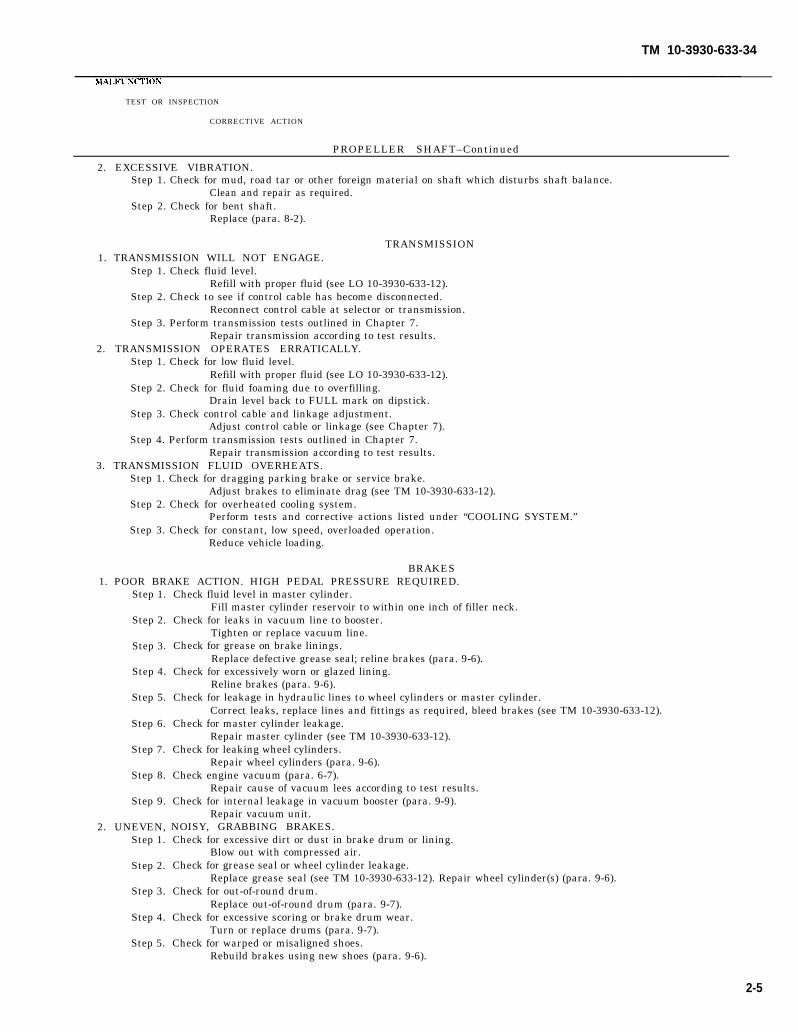
2. EXCESSIVE VIBRATION.Step 1. Check for mud, road tar or other foreign material on shaft which disturbs shaft balance.
Clean and repair as required.Step 2. Check for bent shaft.
Replace (para. 8-2).
TRANSMISSION1. TRANSMISSION WILL NOT ENGAGE.
Step 1. Check fluid level.Refill with proper fluid (see LO 10-3930-633-12).
Step 2. Check to see if control cable has become disconnected.Reconnect control cable at selector or transmission.
Step 3. Perform transmission tests outlined in Chapter 7.Repair transmission according to test results.
2. TRANSMISSION OPERATES ERRATICALLY.Step 1. Check for low fluid level.
Refill with proper fluid (see LO 10-3930-633-12).Step 2. Check for fluid foaming due to overfilling.
Drain level back to FULL mark on dipstick.Step 3. Check control cable and linkage adjustment.
Adjust control cable or linkage (see Chapter 7).Step 4. Perform transmission tests outlined in Chapter 7.
Repair transmission according to test results.3. TRANSMISSION FLUID OVERHEATS.
Step 1. Check for dragging parking brake or service brake.Adjust brakes to eliminate drag (see TM 10-3930-633-12).
Step 2. Check for overheated cooling system.Perform tests and corrective actions listed under “COOLING SYSTEM.”
Step 3. Check for constant, low speed, overloaded operation.Reduce vehicle loading.
BRAKES1. POOR BRAKE ACTION. HIGH PEDAL PRESSURE REQUIRED.
Step 1.
Step 2.
Step 3.
Step 4.
Step 5.
Step 6.
Step 7.
Step 8.
Step 9.
2. UNEVEN,Step 1.
Step 2.
Step 3.
Step 4.
Step 5.
Check fluid level in master cylinder.Fill master cylinder reservoir to within one inch of filler neck.
Check for leaks in vacuum line to booster.Tighten or replace vacuum line.
Check for grease on brake linings.Replace defective grease seal; reline brakes (para. 9-6).
Check for excessively worn or glazed lining.Reline brakes (para. 9-6).
Check for leakage in hydraulic lines to wheel cylinders or master cylinder.Correct leaks, replace lines and fittings as required, bleed brakes (see TM 10-3930-633-12).
Check for master cylinder leakage.Repair master cylinder (see TM 10-3930-633-12).
Check for leaking wheel cylinders.Repair wheel cylinders (para. 9-6).
Check engine vacuum (para. 6-7).Repair cause of vacuum lees according to test results.
Check for internal leakage in vacuum booster (para. 9-9).Repair vacuum unit.
NOISY, GRABBING BRAKES.Check for excessive dirt or dust in brake drum or lining.
Blow out with compressed air.Check for grease seal or wheel cylinder leakage.
Replace grease seal (see TM 10-3930-633-12). Repair wheel cylinder(s) (para. 9-6).Check for out-of-round drum.
Replace out-of-round drum (para. 9-7).Check for excessive scoring or brake drum wear.
Turn or replace drums (para. 9-7).Check for warped or misaligned shoes.
Rebuild brakes using new shoes (para. 9-6).
2-5
TM 10-3930-633-34
MALFUNCTION
TEST OR INSPECTION
CORRECTIVE ACTIONBRAKE S— Continued
2. UNEVEN, NOISY, GRABBING BRAKES–ContinuedStep 6. Check for frozen (corroded) master cylinder or wheel cylinder pistons.
Repair defective cylinders.Step 7. Check for glazed linings.
Remove glaze from linings. Use sandpaper P-P-101.3. BRAKES DO NOT RELEASE.
Step 1. Check for improperly adjusted brake pedal (see TM 10-3930-633-12).Adjust pedal free travel.
Step 2. Check for restricted by-pass port in master cylinder.Rebuild master cylinder (sad TM 10-3930-633-12).
Step 3. Check for swollen master cylinder cups.Rebuild master cylinder (see TM 10-3930.633-12).
Step 4. Check for sticking wheel cylinders.Rebuild wheel cylinders (para. 9-6).
Step 5. Check for broken return springs, warped or misaligned shoes or backing plate.Overhaul brakes (para. 9-6).
REAR AXLE1. CONTINUOUS NOISE FROM AXLE.
Step 1. Check for low lubricant level.Refill to proper level (see LO 10-3930-633-12 and TM 10-3930-633.12).
Step 2. Check for uneven tire sizes or pressure.Install correct tire size and inflate to proper pressure (45 PSI).
Step 3. Check rear wheel bearings for wear.Adjust or replace wheel bearings as required (see TM 10-3930-633-12).
Step 4. Check for loose mounting bolts around differential mounting or reduction gearcase.Tighten loose mounting bolts.
Step 5. Disassemble differential and check for missing gear teeth, worn bearings, broken parts, etc.Repair or replace as required (para. 10-4).
Step 6. Disassemble reduction gear case and check for missing gear teeth, worn bearings, broken parts, etc.Repair or replace as required (para. 10-3).
2. NOISE FROM AXLE ON TURNS ONLY.Step 1. Check adjustment of rear wheel bearings.
Adjust rear wheel bearings as required (see TM 10-3930-633-12).Step 2. Remove and disassemble differential; check for damaged side gears, pinions, etc.
Repair or replace as required (para. 10-4).
STEERING/FRONT AXLE/SPRINGS1. STEERING REQUIRES EXCESSIVE EFFORT.
Step 1. Check for low air pressure in tires.Inflate tires to proper air pressure (45 PSI rear, 100 PSI front).
Step 2. Check for stiffness in tie rod ends, steering knuckles and steering gear due to lack of lubrication.Lubricate all items in accordance with LO 10-3930-633-12.
Step 3. Check for bent or misaligned tie rod or drag link.Replace damaged drag link. Repair tie rod (para. 11-2).
2. TRACTOR WANDERS OR WEAVES.Step 1. Check front wheel toe-in.
Adjust to specifications (para. 11-2),Step 2. Check for loose drag link connections.
Tighten drag link ball stud ends to eliminate play in steering linkage.Step 3. Check for excessive play in front wheel bearings.
Adjust front wheel bearings to specification (see TM 10-3930.633-12).Step 4. Check for excessive play in steering gear due to wear.
Overhaul steering gear (para. 11-3).Step 5. Check for loose steering gear mounting bolts.
Tighten all steering gear mounting bolts.3. NOTICEABLE PULL TO ONE SIDE.
Step 1. Check front tires for mismatch, or low air pressure.Install tires of same size on both wheels. Inflate to 100 PSI (front wheels).
Step 2. Check wheel bearings for tight adjustment.Adjust wheel bearings to eliminate binding (see TM 10-3930-633.12),
Step 3. Check tie rod adjustment/wheel alignment.Align front wheels (para. 11-2).
2-6
TM 10-3930-633-34
MALFUNCTION
TEST OR INSPECTION
CORRECTIVE ACTION
STEERING/FRONT AXLE/SPRINGS–Continued3. NOTICEABLE PULL TO ONE SIDE–Continued
Step 4. Check for dragging brake shoe on one side.Adjust brake to eliminate shoe drag (see TM 10-3930-633-12).
4. NOISE FROM FRONT AXLE.Step 1. Check wheel mounting nuts for security.
Tighten as required.Step 2. Check wheel bearing adjustment.
Adjust wheel bearings (see TM 10-3930-633-12).5. SHIMMY OR WOBBLE.
Step 1. Check for loose spring shackle or U-bolt.Tighten and replace parts as required.
Step 2. Check for broken spring leaf.Replace spring (para. 12-3).
Step 3. Check for bent axle or steering knuckle arm.Straighten or replace parts as required.
Section III. GENERAL MAINTENANCE
2-4. GeneralInstructions within this section provide for
removal and repair of all major components andassemblies of the vehicle. It is assumed thatorganizations undertaking such depth of repairshall have proper facilities and equipment forproper performance of the work. The followingparagraphs 2-5 through 2-10 provide generalinstructions to be used as a guide in performingdisassembly, cleaning, inspection, repair, andreassembly.
CAUTIONPrior to performing any repair bywelding, refer to paragraph 2-11 forspecific instructions regarding weldingof highly stressed parts.
2-5. General Removal Instructionsa. Before attempting removal of any electrical
component, make certain that the system is notenergized. Disconnect battery ground strap.
b. Insure that adequate clearance is availablefor removal of the component. Disassemble thetruck to the extent necessary to provide adequateworking clearance.
c. Use a chain hoist, jack or other aid whenlifting the heavier components. The lifting deviceshould be positioned and attached to the com-ponent to remove all strain from the mountinghardware before the last of the hardware isremoved.
d. To facilitate reassembly and installation,apply identifying tags to mating ends of electricor hydraulic lines as they are disconnected.
Identify parts of similar configuration to insurecorrect reassembly.2-6. General Disassembly
a. Preformed packings, gaskets, seals, andsimilar material should be discarded whenremoved. Do not use metal tools to removesealing material. To prevent damage to matingsurfaces, use wood or plastic as probes.
b. Cotter pins, lockwashers, lockwire, self-locking nuts, and any similar locking devicesshall be discarded when removed.
c. To facilitate reassembly and installation,apply identifying tags to mating points of electricand hydraulic lines, etc., when they aredisconnected. Identify parts of similar con-figuration to ensure correct reassembly.
d. To prevent moisture and foreign matterfrom entering open housings, lines, and otheropenings, apply protective covers as soon aspractical after disassembly. Wrap all parts inclean paper or dip parts in preservative oil,Military Specification MIL-C-8188, or equivalent.
e. Remove only those parts requiring repair orreplacement. Do not disassemble a componentany further than necessary to accomplish neededrepairs.2-7. General Cleaning
a. When cleaning ball or roller bearings, placethem in a basket and suspend them in a containerof dry cleaning solvent overnight. If necessary,use a brush to remove caked grease, chips, etc.Avoid rotating the bearing before solid particles
2-7

TM 10-3930-633-34
are removed to prevent damaging races and balls.When bearings have been cleaned, spin themimmediately in light lubricating oil to removesolvent.
b. Do not clean preformed packings or otherrubber parts in dry cleaning solvent. These partsshould be wiped clean with a clean, dry, lint-freecloth.
c. Prior to disassembly of the vehicle, theexterior parts of the equipment should bethoroughly cleaned to remove accumulated mud,tar, and grease. This procedure will facilitateinspection and disassembly. For cleaning exteriorparts, use a vapor pressure spray rinse cleaner.
d. For cleaning the exterior of the engine,frame and hoods, use Gun, Engine, KeroseneSpray, Stock No, 7900-402730, or equivalent. UseCompound, Aircraf t Cleaning , Mi l i tarySpecification MIL-C-25769, in a mixture con-sisting of one part compound with four to nineparts dry cleaning solvent, Federal SpecificationP-D -680. Allow application to remain on itemsurface for approximately 10 minutes beforerinsing. Rinse with hot or cold water underpressure. If available, use hot water under 80 to120 pounds pressure. An ordinary garden hosewith nozzle may be used if other equipment is notavailable. Rinse thoroughly.
CAUTIONDo not clean tires, lubricant seals,rubber hoses, or electrical componentswith preceding cleaning agent.
e. Electrical parts, such as coils, junctionblocks, switches, and wiring, incorporating in-sulating materials should not be soaked orsprayed with cleaning solutions. Clean theseparts with a clean, lint-free cloth moistened withdry cleaning solvent, Federal Specification P-D-680.
f. Oil and fuel tanks and similar reservoirsshould be flushed, using a spray gun and drycleaning solvent.
CAUTIONDo not use soap or alkalies for cleaning
tank interiors.g. The cooling system radiator core should be
cleaned with steam or hot water. If sedimentwithin the core cannot be completely removed bythis method, the core may be boiled in a solutionof sodium carbonate and water. Use a solution ofone pound of sodium carbonate, FederalSpecification O-S-571, to each gallon of water.Flush with clean, hot water, or steam.
h. The electrical system battery exteriorsurfaces should be cleaned with a weak solution ofbaking soda and water. Apply the solution with a
bristly brush to remove anythe battery cable clampsbattery tray.
corrosive buildup onand terminals and
i. When cleaning h y d r a u l i c s y s t e m c o r n - ponents, use petroleum-free solvents. Clean anddry parts thoroughly to make sure that no residueremains. If a coating of preservative is requiredprior to reassembly, apply a light film of preservative oil, Military Specification MIL-O-6083. If petroleum-free solvents are not availablefor cleaning, use hydraulic fluid compatible withthat used in the vehicle system.
CAUTIONDo not use gasoline or other petroleumbase products to clean or preservehydraulic system components.
j. Wash painted surfaces of vehicle with asolution consisting of ¼ lb of soap chips, FederalSpecification P-S-579, to 1 gallon of water.
2-8. General Inspectiona. Examine bearings for rusted or pitted balls,
races, or separator. Examine balls and races forbrinnelling, abrasion, and serious discoloration.The following are causes for bearing rejection.
(1) Cuts or grooves parallel to ball or rollerrotation.
(2) Fatigue pits (as opposed to minormachine marks or scratches).
(3) Cracks detected during magnetic particleinspection.
NOTEExcluding defects which may cause bearing bindingor misalignment, nicks or gouges outside race loadareas are not cause for rejection.
b. Inspection consists of checking for defectssuch as physical distortion, wear, cracks, andpitting, and checking dimensions of parts forcompliance with maximum wear limits data.Parts subjected to heavy load or pressure shall beinspected more thoroughly by performing surfacetemper, magnetic particle, or f luorescentpenetrant procedures where necessary. Clean allparts before inspection.
c. When removing drain plugs from trans-mission, engine, or hydraulic system com -ponents, inspect the sediment adhering to theplug. Accumulations of grit and/or fine metalparticles may indicate actual or potential com-ponent failure. A few fine particles are normal.This inspection is effective in determiningdefective parts prior to internal inspection of thecomponent, and to predict degradation of theequipment.
d. Gears should be inspected upon removal fort h e f o l l o w i n g c o n d i t i o n s : -
2-8

TM 10-3930-633-34
(1) Normal wear in excess of practical limits.(2) Pitting of teeth due to extreme pressure
loading.(3) Abrasive wear due to foreign materials in
lubricant.(4) Scoring, seizing, and galling of teeth due
to excessive loads and clearance.(5) Burning and loss of temper due to ex-
treme high temperature operation. Caused byexcessive friction and lack of lubrication.
(6) Rolling or plastic yielding due to extremeloads over a long period.
(7) Cracks and fractures due to shock.loading.
NOTEIf visual inspection proves the service of gearsdoubtful, perform a surface temper or magneticparticle inspection, or both.
e. Inspect shaft splines for wear, pitting,rolling or peening, and for fatigue cracks. Inmany instances, the same inspection procedurewill apply as for gears. However, the condition, ifever present, will in most cases be much lesspronounced. When doubtful of the actual ser-viceable condition of splines, perform a magneticparticle inspection.
f. Check all hose surfaces for broken or frayedfabric. Check for breaks caused by sharp kinks orrubbing against other parts of the truck. Inspectcopper tubing lines for kinks. Inspect the fittingthreads for damage. Replace any part founddefective. Following reassembly and duringinitial truck operation period, check for leaks.
g. Visually inspect all castings and weldmentsfor cracks. Parts upon which great stress is placedmay be inspected further, using the magneticparticle inspection method. Critical non-ferrousparts may be fluorescent penetrant inspected.
h. Inspect all harnesses for chaffed or burnedinsulation. Inspect all terminal connectors forloose connections and broken parts.
2-9. General Repaira. Remove burrs from gear teeth with a fine-
cut file or hand grinder.b. Alternator sliprings and starter com-
mutators may be polished in a lathe, using a stripof 00 sandpaper. After polishing, blow all dustand residue from commutator with compressedair.
c. Chassis and exterior painted parts may beresurfaced where paint is damaged, or whereparts have been repaired, by using an abrasivedisc driven through a flexible shaft.
CAUTIONSuitable precautions should be taken to
guard other parts of the vehicle fromabrasive dust. The operation should notbe performed near exposed workingparts and all openings which would allowthe dust to reach working parts shouldbe masked.
d. Remove residue and oil stain from bearingraces with crocus cloth.
e. Prior to resurfacing, scrape off loose andblistered paint from damaged areas. Clean area tobe painted by sanding or buffing. Remove residuecleaning material with paint thinner, FederalSpecification TT-T-306, and dry thoroughly.
f. During repair operations, bare steel surfacesshall be protected from oxidation when not ac-tually undergoing repair work, i.e., whileawaiting any repair step, re-inspection orreassembly. Such protection shall be ac-complished by dipping the parts in, or sprayingthem with corrosion preventive compound,Military Specification MIL-C-6259. The sameprotective coating shall be applied to othermetals, if necessary to prevent oxidation underclimatic or atmospheric conditions prevailing.Aluminum parts may require protection in at-mospheres having a high salt content. Steel partsmust be protected in all instances.
NOTEThe above instruction is applicable to polished andmachined steel parts not protected by cadmium, tin,copper, or other plating or surface treatment. Baremetal surfaces must be free of moisture when applied.Acid present in perspiration and skin oils may attacksteel surfaces if fingerprints are not removed. Dipparts in fingerprint remover compound, MilitarySpecification MIL-C-15074, after handling, to preventsuch action.
g. Welding and brazing processes may beemployed for the repair of cracks in external steelparts, such as brackets, panels, and lightframework. Refer to paragraph 2-11 for specificwelding instructions.
h. Replace all broken, worn, or burned elec-trical wiring. Wires on which several strands arebroken must be replaced. Broken strands willincrease the resistance of the wire and impairefficiency of the electrical components, especiallythe ignition system.
i. Replace all broken, frayed, crimped, or softflexible lines and hoses. Replace fittings which arestripped or damaged. Replace entire flexible hoseif fittings are damaged. Make sure the hoseclamps do not crimp hoses.
j. Replace any bolt, screw, nut, or fitting onwhich threads are damaged. Inspect tapped holesfor thread damage. If cross-threading or spalling
2-9

TM 10-3930-633-34
is evident, retap the hole for the next oversizescrew or stud. When retapping will result inweakening the part, or when the cost of the partmakes retapping impractical, replace thedamaged part. At times, merely chasing thethreads with the proper size tap or die will beadequate.
2-10. General Reassemblya. Remove protective grease coatings from new
parts prior to installation.b. To replace a preformed packing, first
dovetail groove, then stretch packing and placeinto position. Rotate component on flat surface,applying a downward pressure to uniformly pressthe packing into position.
c. To provide added sealing for gaskets, coatboth sides with non-hardening oil resistantsealing compound (MIL-S-45180B). Be sure thatall traces of previous gasket and sealant areremoved before installing new gasket,
d. Install oil seals with seal lip facing in,applying an even force to the outer edge of seal.Coat oil seals evenly with oil or grease beforeinstalling. If oil seals are to be installed overkeyed or splined shafts, use a guide to preventsharp edges of the keyway of splines from cuttingthe leather or neoprene seal. Guides can beconstructed of very thin gage sheet metal andshaped to the required diameter. However, makecertain the guide edges are not sharp and are bentslightly inward so they do not cut the seal.
e. During reassembly of shafts and bearings inhousing, first mount bearing on shaft, then installthe assembly by applying force to the shaft.When mounting bearings on shafts, always applyforce to the inner races.
f. Lubricate all preformed packings with a thincoating of light mineral oil before installation.
g. Lubricate bearings prior to reassembly withthe type of lubricant normally used in the relatedhousing or container. This will provide lubricationduring the first run-in until lubricant from thesystem can reach the bearings.
2-11. Repair Welding
2-12. GeneralThe manufacturer has historically opposed field
repair of critical components of any of theirproducts. It is recommended, rather, that thefailed or damaged component be replaced at thelowest serviceable level. The manufacturer does,however, recognize that situations may arise inwhich replacement of the part(s) is not feasible forreasons of time limitations, spare parts short-ages, etc.
a. In those cases of emergency where weldingrepair is apparently the only practical means ofrestoring the serviceability of the vehicle, theinstructions given below must be rigidly followed.
b. Personnel should be cautioned againstadding brackets and attachments by welding forpersonal interests. The nature of this practiceinvites disregard for good welding design,. as wellas creating unnecessary visibility problems forthe operator.
2-13. Welding PracticesThe surfaces of parts to be welded shall be free
from paint, grease, and scale which can beremoved by chipping and wire brushing, andother foreign matter. When multiple layers ofweld metal are required, each layer shall bethoroughly cleaned before depositing anotherlayer. All welded parts and assemblies shall befree from cracks and other imperfections that mayreduce the effectiveness of the part or assembly.All weldments shall be free from slag, flux, weldspatter, and other impurities detrimental to thestrength and soundness of the weld. Work shallbe positioned for flat welding whenever prac-ticable. Butt type joints having members of equalthickness shall be aligned within 10 percent of thethickness of the members involved. Weldmentsshall be free from overlays. Undercut in weld-ments of type 2 and type 3 steels shall not be morethan 0.01 inch deep when its direction is trans-verse to the primary stress in the part that isundercut. Undercut shall be not more than 1/32-inch deep when its direction is parallel to theprimary stress in the part that is undercut.
2-14. Pre-inspectiona. The area of the machine to be repaired must
be thoroughly cleaned. Steam-cleaning of theentire machine is recommended.
b. It must be remembered that whenever afailure occurs in any component, the same shockforces causing the failure have been presentelsewhere in that component, and have beentransmitted throughout the structure whereverthere is resistance to that force. Because of thisfactor, a thorough inspection of all members andweld joints so affected must be made, such as:
(1) Reactive frame members(2) Spring shackles(3) Engine mounts(4) Transmission mounts
c. The use of magnetic particle and/or dyepenetrant techniques of nondestructive testingfor this inspection are highly recommended.
2-10

TM 10-3930-633-34
2-15. Safetya. Protect-o-seal (anti-flashback) fuel tank cap
must be in place before grinding, burning, orwelding. Preferred procedure is to empty the fueltank and purge with CO2.
CAUTIONBefore attaching welding ground cable tothe machine, be sure that the alternatorharness and/ or battery cables aredisconnected. This is to prevent burningout the diodes in the alternator becauseof reverse polarity.
b. Always wear helmet, asbestos gloves,suitable shoes, apron, or other suitably protectiveclothing when welding.
c. Clothing should be heavy, free from oil orgrease. Pockets and cuffs should be protectedagainst sparks and slag.
d. Portable grinders should have proper wheelguards. Operator should be equipped withgoggles or safety shield.
e. Always use proper torch, tip, electrode, andholder for the job.
f. Maintain good welding cables, preferablyprotected by loom.
g. Ground cables to work, never to housesystems, hoists, chain falls, etc. Attach weldingground cable to one of the two members beingjoined. Do not run current through bearings orwear surfaces.
h. Welding area should be clean and dry.i. Oxygen should never be used as compressed
air, in cleaning or drying operations.j. Do not use rope to suspend work when
flame-cutting, grinding, or welding.
2-16. Fire Protectiona. Remove work from hazardous area before
cutting or welding. If this is not possible, removeflammable material from work area, or cover withflame arresting material.
b. Correct those conditions where sparks orslag can travel into combustible materials.
c. Keep oil or grease separated from oxygen.This combination is explosive if ignited.
d. Do not allow clothing to collect pureoxygen. In this concentrated or oxygen-enrichedcondition, materials burn violently.
e. Keep fully charged fire extinguishersnearby. Employ standby assistant with ex-tinguisher during unavoidable hazardous con-ditions.
2-17. Ventilationa. Fans on welders and work help to assure
good ventilation. Adequate exhaust fans are
essential. However, a breeze directed on the arccan destroy the gas shield around the arc.
b. Never use oxygen for ventilation, or as airjet.
c. Avoid all welding or cutting in paint booths,around dip tanks, decreasing, or other naturallyhazardous areas.
d. Excessive or continued breathing of smoke,toxic fumes, or dust is injurious. Use respirator inaddition to ventilation under severe conditions.
e. Keep all air in work area moving towardexhaust system.
2-18. Filler Metalsa. All stick electrodes for subject contract
joints must be low hydrogen coated (herein calledL.H.). L.H. electrode E-7018 (AWS Class.) isrecommended, except when specially noted.
b. E-7019, E-8018, E-9018, E-10018, E-11018have AC-DC polarity, reversing current, with acoating of low hydrogen iron powder.
c. L.H. electrodes are supplied from the vendorin hermetically sealed containers, and must havestorage care normal to their type. If containershave been opened for electrodes to become ex-posed to normal (and above) atmospherichumidity, the electrodes should be oven baked at700 °F. for 1 hour minimum.
d. L. H. electrodes which have been in watershould be scrapped.
e. Remove only enough electrodes from thecontainer to perform the immediate job. Opencontainers should be stored in heated storagecontainers held at 2000 to 300 °F.
f. The manufacturer employs little or no TIGproduction welding at the factory.
g. The manufacturer employs MIG weldingextensively in production welding. Due to itsnature however, the welding instruction herein(repair, as opposed to production welding) willdeal only with stick electrodes. The precautionaryand preparation instruction herein applies also toMIG or TIG welding.
2-19. Preparationa. In natural ambient temperatures of 60 °F or
less, the machine (or component) should be “roomsoaked” overnight in 70 °F (+) to equate apreheat. If this is impossible, the weld zone (area6“ to 10” each side) should be preheated to aminimum of 100 °F. before welding. Thisminimum temperature should be maintained onthe heat zone of each joint until that joint iscompleted.
b. Thermal sticks may be used to check theseweld heat-affected zones. Timpil sticks are
2-11
TM 10-3930-633-34
available from welding suppliers in 50° in-crements from 100 °F through 2200 °F.
c. All cracks in the damaged area, or in areaslisted in paragraph 2-14 above, must be groove-ground the entire length of the crack, and theentire crack removed. Any weld repair must bemade on sound material.
d. No notches, gouges, or craters should be leftin the area of weld repair, but must be weld-filledand ground to the original contour before repairwelding. Preparation for weld assumes smoothsurfaces and contours easily accessible to the weldarc.
e. Finish grind marks after welding (if any) onany surface should not exceed 63 microinches,and should run in the direction of the load. Whenrequired, a disc grinder with #80 grit abrasive isrecommended.
2-20. Weldinga. Welding should be performed by ex-
perienced/qualified welders.b. Voltage/amperage/speed settings should be
balanced to produce a well-formed bead, and toassure proper penetration.
c. For subject component welding, thefollowing ranges apply for E-7018, E-8018, E-9018 and E-10018 electrodes: Manufacturersrecommendation for arc length and amperage is tobe followed. These ranges must be balanced per babove.
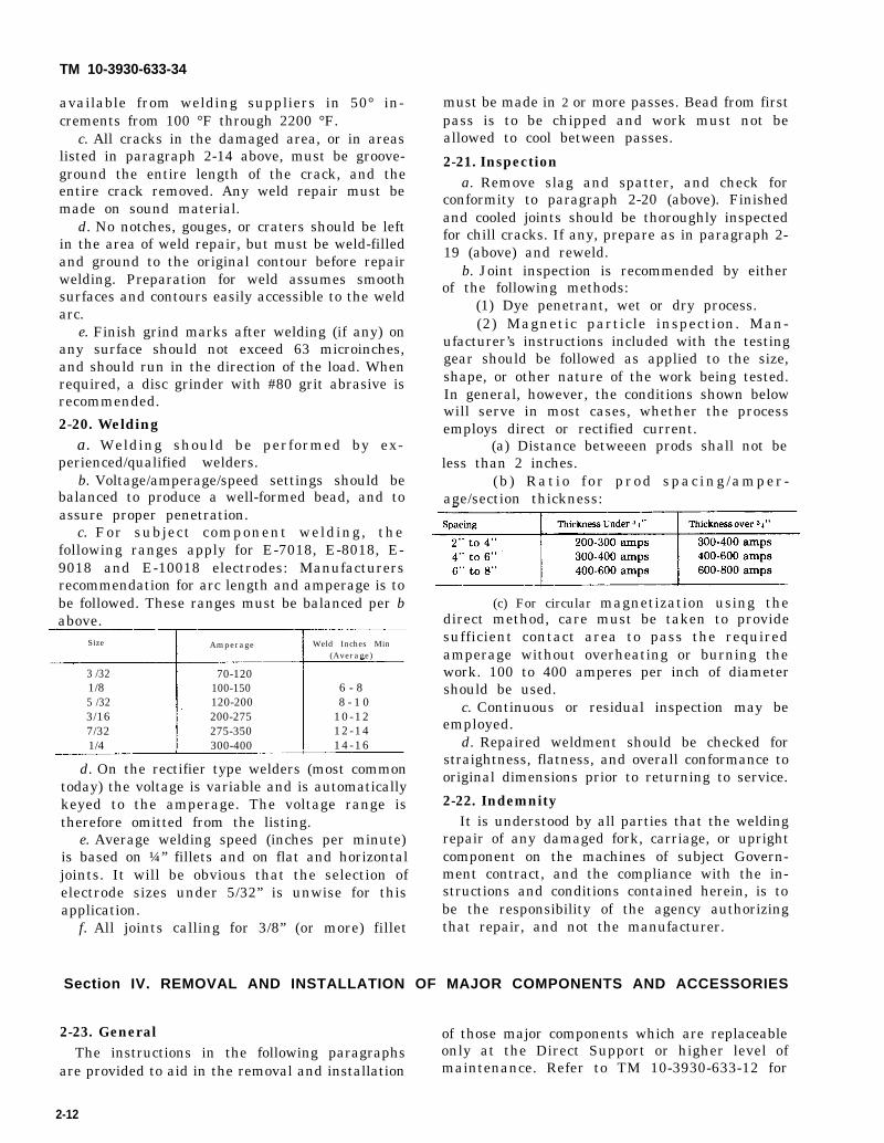
Size Amperage Weld Inches Min(Average)
3 /32 70-1201/8 100-150 6 - 85 /32 120-200 8 - 1 03/16 200-275 10-127/32 275-350 12-141/4 300-400 14-16
d. On the rectifier type welders (most commontoday) the voltage is variable and is automaticallykeyed to the amperage. The voltage range istherefore omitted from the listing.
e. Average welding speed (inches per minute)is based on ¼” fillets and on flat and horizontaljoints. It will be obvious that the selection ofelectrode sizes under 5/32” is unwise for thisapplication.
f. All joints calling for 3/8” (or more) fillet
must be made in 2 or more passes. Bead from firstpass is to be chipped and work must not beallowed to cool between passes.
2-21. Inspectiona. Remove slag and spatter, and check for
conformity to paragraph 2-20 (above). Finishedand cooled joints should be thoroughly inspectedfor chill cracks. If any, prepare as in paragraph 2-19 (above) and reweld.
b. Joint inspection is recommended by eitherof the following methods:
(1) Dye penetrant, wet or dry process.(2) Magnetic particle inspection. Man-
ufacturer’s instructions included with the testinggear should be followed as applied to the size,shape, or other nature of the work being tested.In general, however, the conditions shown belowwill serve in most cases, whether the processemploys direct or rectified current.
(a) Distance betweeen prods shall not beless than 2 inches.
(b ) Rat io for prod spac ing /amper -age/section thickness:
(c) For circular magnetization using thedirect method, care must be taken to providesufficient contact area to pass the requiredamperage without overheating or burning thework. 100 to 400 amperes per inch of diametershould be used.
c. Continuous or residual inspection may beemployed.
d. Repaired weldment should be checked forstraightness, flatness, and overall conformance tooriginal dimensions prior to returning to service.
2-22. IndemnityIt is understood by all parties that the welding
repair of any damaged fork, carriage, or uprightcomponent on the machines of subject Govern-ment contract, and the compliance with the in-structions and conditions contained herein, is tobe the responsibility of the agency authorizingthat repair, and not the manufacturer.
Section IV. REMOVAL AND INSTALLATION OF MAJOR COMPONENTS AND ACCESSORIES
2-23. General of those major components which are replaceableThe instructions in the following paragraphs only at the Direct Support or higher level of
are provided to aid in the removal and installation maintenance. Refer to TM 10-3930-633-12 for
2-12

TM 10-3930-633-34
removal and replacement instructions for thoseassemblies replaceable at organizational levels.Also observe the following special precautions.
a. Before attempting removal of any electricalcomponent, make certain that the system is notenergized. Disconnect battery ground strap.
b. Insure that adequate clearance is availablefor removal of the component. Disassemble thetruck to the extent necessary to provide adequateworking clearance.
c. Use a chain hoist, jack or other aid whenlifting the heavier components. The lifting deviceshould be positioned and attached to the com-ponent to remove all strain from the mountinghardware before the last of the hardware isremoved.
d. To facilitate reassembly and installation,apply identifying tags to mating ends of electricor hydraulic lines as they are disconnected.Identify parts of similar configuration to insurecorrect reassembly.
e. To prevent moisture and foreign matterfrom entering open housings, lines, and otheropenings, apply protective covers as soon aspracticable after disassembly.
2-24. Enginea. Removal.
(1) Remove the two screws attaching thehood to the hinge brackets and remove the hood.
(2) Drain the cooling system and the enginecrankcase (refer to TM 10-3930-633-12).
(3) Disconnect battery cable, and removeground strap at engine connection point.
(4) Remove fan, fan belts, water pumppulley and upper and lower radiator hoses (seeTM 10-3930-633-12).
(5) Remove radiator (see TM 10-3930-633-12).
(6) Disconnect the accelerator and chokecables from carburetor and anchor brackets onengine (refer to TM 10-3930-633-12). Disconnecthose at fuel pump.
(7) Remove air cleaner ductwork fromcarburetor (see TM 10-3930-633-12).
(8) Disconnect exhaust pipe from manifold(see TM 10-3930-633-12). -
(9) Remove transmission oil filter (see figure2-1) from bracket and position filter and hoses outof the way of engine removal. Remove clips fromtransmission oil lines.
Figure 2-1. Preparation for Engine Removal.
(10) Disconnect the engine wiring harness atthe ignition coil, coolant temperature sendingunit, oil pressure sending unit, and vacuumswitch.
(11) Loosen and remove the alternatormounting bolts, and position alternator (withwiring attached) out of the way of engineremoval.
(12) Raise the vehicle, using lifting eyes onthe frame, and block securely under the frame forsupport.
(13) Remove the starter (see TM 10-3930-633- 12) and the automatic transmission filler tubebracket.
(14) From underneath the vehicle, removethe converter housing access cover.
(15) Remove the nuts which attach theconverter to the engine flywheel. Use of a wrenchon the crankshaft pulley attaching bolt will enablethe crankshaft to be turned until all nuts areremoved.
(16) Block or brace the converter so that itwill remain in the housing as the engine isremoved.
(17) Refer to figure 2-2 and remove the frontsupport frame bolt and nut. When engine isremoved, insulators and washers may beremoved.
2-13

TM 10-3930-633-34
Figure 2-2. Engine Front Support.
(18) Attach a sling to the engine or liftingeyes, and tighten the hoist arrangement to bearmost of the engine weight.
(19) Remove all converter housing to engineattaching screws. Raise the engine slightly andslide forward to disengage crankshaft from torqueconverter.
(20) Lift engine carefully and guide by handto avoid striking parts of the engine against theframe. If any resistance is felt, stop hoist im-mediately and investigate cause beforeproceeding.
b. Installation.(1) Place a new gasket on the muffler inlet
pipe.(2) Lower the engine carefully into place on
the chassis. Make sure that front mount parts arearranged as shown in figure 2-2.
(3) Observe the engine to transmissionconverter housing flange and make sure that theconverter pilot enters the crankshaft and that thedowel pins in the engine block engage the con-verter housing holes properly.
(4) Install engine to converter housing bolts.
Lower engine fully on front support and removelifting sling.
(5) Install frame bolt and nut through enginefront support. Torque to 35 to 50 ft/lbs.
(6) Position the transmission oil filterassembly on the bracket as shown in figure 2-1,and install the three screws to secure filter tobracket. Install clips over oil lines on engineblock.
(7) Install the starter (see TM 10-3930-633-12). Connect starter cables, and install thetransmission filler tube bracket.
(8) Attach the exhaust pipe to the manifoldflange. Torque the nuts to 25 to 35 ft/lbs.
(9) Connect the engine ground strap.(10) Connect the vacuum line at the intake
manifold. Connect the choke cable and acceleratorcables to the carburetor and anchor brackets. Besure the retracting spring is properly installed.
(11 ) Connect the engine wiring harness atthe coil, vacuum switch, coolant temperaturesender, and oil pressure sender.
(12) Install the alternator (see TM 10-3930-633-12) but do not tighten mounting bolts.
(13) Install radiator (see TM 10-3930-633-12). Connect oil cooler lines and install upper andlower radiator hoses.
(14) Install fan pulley, fan belts and fan.Torque fan bolts to 40 to 45 ft/lbs.
(15) Adjust fan belt tension and tightenalternator mounting bolts (see TM 10-3930-633-12).
(16) Install air cleaner ductwork. Connecthose to fuel pump.
(17) Install and adjust hood.(18) Connect battery cables.(19) Fill and bleed cooling system. Fill the
engine crankcase (see TM 10-3930-633-12). Startthe engine check for leakage. Adjust idle speedand mixture.
2-25. Transmissiona. Removal.
(1) Remove the screws along the floor plate,and lift off the transmission cover in theoperator’s compartment. Disconnecting theaccelerator pedal will simplify removal of thetransmission cover.
(2) Disconnect the parking brake link fromthe brake lever mechanism, and swing thetransmission cover up and out of the way.
(3) Disconnect the push-pull control cable atthe transmission linkage on the side of thetransmission case. Remove locknuts from cablehousing to free the cable from the anchor bracket(fig. 2-3).
2-14

TM 10-3930-633-34
Figure 2-3. Transmission Mounting.
(4) Raise the vehicle and block the framesecurely.
(5) Place a drain pan under the transmissionfluid pan. Starting at the rear of the pan andworking toward the front, loosen the attachingbolts and allow the fluid to drain; finally removeall of the pan attaching bolts except two at thefront, to allow the fluid to further drain. After thefluid has drained, install two bolts on the rear sideof the pan to temporarily hold it in place.
(6) Remove the converter drain plug accesscover from the lower end of the converter housing.
(7) Remove the converter-to-flywheel at-taching nuts. Place a wrench on the crankshaft
pulley attaching bolt to turn the converter to gainaccess to the nuts.
(8) With the wrench on the crankshaft pulleyattaching bolt, turn the converter to gain accessto the converter drain plug. Then, remove theplug. Place a drain pan under the converter tocatch the fluid. After the fluid has drained fromthe converter, reinstall the plug.
(9) Wedge the converter to hold it in placewhen the transmission is removed.
(10) Disconnect the starter cable from thestarter, and disconnect the transmission to bodyground cable from the transmission. Remove thestarter (see TM 10-3930-633-12).
2-15

TM 10-3930-633-34
(11) Disconnect oil cooler lines on the rightside of the transmission case. Plug or seal theports and hose ends to prevent contamination.Disconnect vacuum line at left rear of trans-mission.
(12) Remove the four nuts which attach thedrive shaft companion flange to the parking brakedrum.
(13) Support the transmission on a trans-mission jack. Secure the transmission to the jackwith safety chain. Remove both engine rearsupport bolts.
(14) With the transmission jack, raise theengine and transmission high enough to removethe engine rear supports.
(15) Lower the engine against a floor standor engine support bar so that the converterhousing is clear of the crossmember when allweight is off the transmission jack.
(16) Remove the remaining converterhousing-to-engine attaching bolts. Move theassembly toward the rear and lower it, leaving theflywheel attached to the crankshaft. If additionalclearance is needed, tilt the rear of the assemblyupright slightly and to the rear (enough to allowremoval of the six flywheel to crankshaft bolts).Move the assembly to the rear, and remove it.
b. Installation.(1) Torque the converter drain plug to 15 to
28 ft/lbs.(2) If the converter has been removed from
the converter housing, carefully position theconverter to the transmission making sure theconverter drive flats are fully engaged in thepump gear. Install a wedge to prevent the con-verter from slipping out of the housing.
(3) With the converter properly installed,place the transmission on the jack. Secure thetransmission to the jack with safety chain.
(4) Rotate the converter so that the studsand drain plug are in alignment with their holes in
the flywheel.(5) Raise transmission and converter with
the jack to align it with the engine. Remove thewedge from the converter housing. Carefullymove the converter and transmission assemblyforward into position, using care not to damagethe flywheel and converter pilot. THE CON-VERTER MUST REST SQUARELY AGAINST
THE FLYWHEEL. THIS INDICATES THATTHE CONVERTER PILOT IS NOT BINDINGIN THE ENGINE CRANKSHAFT.
(6) Install the lower converter housing-to- engine bolts. Torque the bolts to 40 to 50 ft/lbs.Remove the safety chain from the transmission.
(7) Raise the engine and transmission with the transmission jack, and remove the enginesupport stand or support bar.
(8) Install the rear support insulators asshown in figure 2-3.
(9) Lower the engine and transmissionagainst the supports, and at the same time installthe support bolts and torque to 20 to 30 ft/lbs.
(10) Install and torque the four converter-to-flywheel attaching nuts to 23 to 28 ft/lbs. Installthe converter housing access cover and secure itwith the attaching bolts at 12 to 16 ft/lbs.
(11 ) Connect the oil cooler inlet and outletlines to the transmission.
(12) Install the vacuum line and retainingclips. Install the vacuum hoses on the vacuumunit.
(13) Coat the universal joint knuckle withtransmission fluid, and install the companionflange to parking brake drum.
(14) Connect the push-pull cable to theextension lever, and secure the cable housing tothe anchor bracket (see figure 2-3).
(15) Install the starter motor and cables (seeTM 10-3930-633-12).
(16) Connect the fluid filler tube.(17 ) Lower the vehicle and install the upper
converter housing to engine bolts, and torque to40 to 50 ft/lbs.
(18) Install transmission cover to floor plate.(19) Refill transmission. Complete refill
requires approximately 11 quarts of fluid (LO 10-3930-633-12).
(20) Start engine and check transmissionand converter for leaks, and check generaloperation.
2-26. Rear Axle and Reduction Gearcase
a. Removal.(1) Jack up, or hoist the entire vehicle high
enough off the work surface to provide adequateworkingremoval,
space underneath the frame for axleSee fig. 2-4.
2-16

TM 10-3930-633-34
Figure 2-4. Rear Axle Removal.
(2) Support the vehicle, using adequate jackstands or blocking under the frame, making surethat the positioning of these supports will notinterfere with axle removal.
(3) Remove rear wheels and tires.(4) Disconnect hydraulic brake line from
master cylinder at the tee fitting mounted next tothe differential carrier. Plug the brake lines toprevent contamination.
(5) Remove differential and gearcase drainplugs and allow units to drain thoroughly.
(6) Remove the four nuts and disconnect thecompanion flange and flange yoke on the driveshaft.
(7) Position an axle jack, or similar device,under the axle housing to support the assemblyonce attaching hardware is removed. Adjust thesupporting device to relieve strain from themounting hardware.
(8) Remove the rear spring bolt and nut fromthe frame bracket at the rear of each spring.
(9) Remove the four bolts and lock nuts andthe mounting plate from the axle spring mountingpad on each side.
(10) Lower the axle jack and axle, andremove from beneath the vehicle.
b. Installation.(1) position rear axle, with reduction
gearcase assembled, under vehicle. The springs
should be pushed down out of the way so that axlecan be properly positioned.
(2) Raise the axle on the axle jack so that thesprings can be rotated up into position. The freeend (rearmost) of the springs should slide betweenthe two frame brackets on each side.
(3) Install the two rear spring bracket boltsand locknuts, and tighten securely. Note that thebolt must be installed below the spring leaves toretain the free end of the spring.
(4) Carefully align the axle so that the centerbolt of the spring fits into the recess under thespring pad on each side of the axle.
(5) Lower the axle so that it just rests on thesprings.
(6) Position the spring plate (as shown infigure 2-4) and secure axle to springs by installingfour bolts and locknuts on each side of the axle.Torque bolts to 50 to 60 ft/lbs.
(7) Connect brake line at tee fitting.(8) Connect flange yoke on drive shaft to
reduction gearcase companion flange and securewith four capscrews and nuts.
(9) Mount rear wheels and tires.(10) Lower vehicle to the ground or floor,
and fill the differential and reduction gearcasewith the proper grade and type of lubricant for theseason, as specified in LO 10-3930-633-12.
(11 ) Bleed the brakes. (Refer to TM 10-3930-633-12. )
2-17
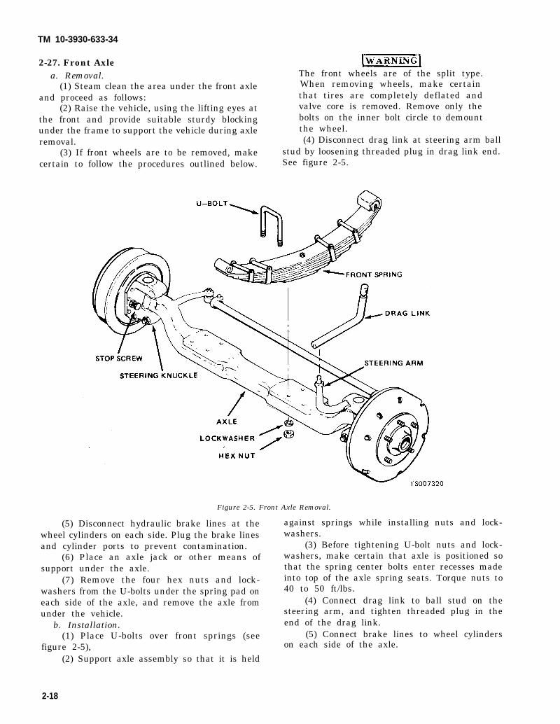
TM 10-3930-633-34
2-27. Front Axlea. Removal.
(1) Steam clean the area under the front axleand proceed as follows:
(2) Raise the vehicle, using the lifting eyes atthe front and provide suitable sturdy blockingunder the frame to support the vehicle during axleremoval.
(3) If front wheels are to be removed, makecertain to follow the procedures outlined below.
The front wheels are of the split type.When removing wheels, make certainthat tires are completely deflated andvalve core is removed. Remove only thebolts on the inner bolt circle to demountthe wheel.(4) Disconnect drag link at steering arm ball
stud by loosening threaded plug in drag link end.See figure 2-5.
Figure 2-5. Front Axle Removal.
(5) Disconnect hydraulic brake lines at thewheel cylinders on each side. Plug the brake linesand cylinder ports to prevent contamination.
(6) Place an axle jack or other means ofsupport under the axle.
(7) Remove the four hex nuts and lock-washers from the U-bolts under the spring pad oneach side of the axle, and remove the axle fromunder the vehicle.
b. Installation.(1) Place U-bolts over front springs (see
figure 2-5),(2) Support axle assembly so that it is held
against springs while installing nuts and lock-washers.
(3) Before tightening U-bolt nuts and lock-washers, make certain that axle is positioned sothat the spring center bolts enter recesses madeinto top of the axle spring seats. Torque nuts to40 to 50 ft/lbs.
(4) Connect drag link to ball stud on thesteering arm, and tighten threaded plug in theend of the drag link.
(5) Connect brake lines to wheel cylinderson each side of the axle.
2-18

TM 10-3930-633-34
(6) Install front wheels and tires. Inflatefront tires to 100 PSI.
(7) Lower vehicle to the ground. Lubricatefront axle (see LO 10-3930-633-12. Bleed thebrake system. (Refer to TM 10-3930 -633-12.)
(8) If axle has been repaired, adjust frontwheel toe-in (see Chapter 12).2-28. Vacuum Power Unit
a. Removal.(1) Turn off engine and set parking brake.(2) Raise hood and remove the left side hood
panel, to expose the brake power unit as shown infigure 2.6.
Figure 2-6. Vacuum Power Unit Installation.
(3) Refer to TM 10-3930-633-12 and removethe master cylinder.
(4) Disconnect the vacuum line at thevacuum unit chamber.
(5) Remove the locknut and disconnect thevacuum unit pushrod.
(6) Remove the four hex nuts and lock-washers from the studs and lift off the vacuumpower unit.
b. Installation.(1) Position the vacuum unit against the
mounting bracket, making certain that thevacuum hose connection is properly oriented.Install the four lockwashers and hex nuts tosecure unit to bracket.
(2) Connect vacuum line..(3) Refer to TM 10-3930-633-12 and install
master cylinder.(4) Connect pushrod to bellcrank and install
. locknut.(5) Install left side hood.(6) Bleed brakes and adjust pedal free travel.
(Refer to TM 10-3930 -633-12.)
2-29.a.
steer
Steering Gear.Removal.(1) Refer to figure 2-7 and disconnecting gear from steering column by removing
capscrews and nuts through the flexible coupling.
Figure 2-7. Steering Gear Mounting,
(2) Remove nut on pitman arm shaft andwork pitman arm off the shaft. Pitman arm maybe disconnected from drag link by looseningthreaded plug in the end of the drag link until thepitman arm ball stud will pull free of the drag linksocket.
(3 ) Remove the three s teer ing gearmounting bolts, and lift out the steering gear.
b. Installation.(1) Install the steering gear to the mounting
bracket as shown in figure 2-7, and secure withthree mounting bolts.
(2) Refill steering gear with the type andgrade of lubricant specified in LO 10-3930-633-12.
(3) Align flexible coupling halves at the baseof the steering column and install the two cap-screws and nuts to secure the coupling.
(4) Position the steering gear in the center ofits travel. Rotate the input shaft slowly fromlock-to-lock and back it off one-half the totaltravel.
(5) With the gear at its midpoint; install thepitman arm so that it is centered in its travelbetween the stop screws. Secure the pitman armby installing and tightening the locknut on the end of the pitman arm shaft.
(6) Connect pitman arm to drag link, and, ifnecessary, adjust drag link length as outlined inTM 10-3930-633-12.
2-19


TM 10-3930-633-34
CHAPTER 3
REPAIR OF ELECTRICAL SYSTEM
Section I. ALTERNATOR
3-1. General
The alternator is an A .C. (alternating current)generator which delivers relatively high output ofenergy at low speeds. The physical characteristicsof the design are discussed below.
a. Operation. The unit consists of a rotatingfield coil, called the rotor, which is supported bybearings and rotates, being driven by the engine,inside an electromagnetic field generated by thestator windings. The stator windings are attachedto the alternator frame. Brushes in the unit pickup the oscillating current from the rotor, and passit through a set of diode rectifiers in the alternatorend frame to produce a D.C. (direct current)output. A voltage regulator is used with thealternator to control the strength of the electricalfields, and therefore the relative values of theoutput .
b. Rotor. The rotor consists of one continuouselectrical winding on the rotor shaft. The shaft issupported by a ball bearing at the drive end and aneedle roller bearing at the brush end. Thebearings are provided with grease reservoirs,eliminating the need for periodic lubrication.
c. Stator and Frame. Stator windings areassembled on the inside of a laminated core thatforms part of the frame. Six rectifier diodes areassembled into the slipring end frame and areconnected to the stator windings.
d. Brushes. Two brushes are used to carrycurrent from the regulator circuit, through thesliprings, to the rotor field coil. Brushes are extralong for extended service.
3-2. Service Precautions
Since the a.c. generator and regulator aredesigned for use on only one polarity system, thefollowing precautions must be observed whenworking on the charging circuit. Failure to ob-serve these precautions will result in seriousdamage to the electrical equipment,
a. When installing a battery, always makeabsolutely sure the ground polarity of the batteryand the ground polarity of the a.c. generator arethe same.
b. When connecting a booster battery. makecertain to connect the negative battery terminals
together and the positive battery terminalstogether.
c. When connecting a charger to the battery,connect the charger positive lead to the batterypositive terminals and the charger negative leadto the battery negative terminal.
d. Never operate the a.c. generator on opencircuit. Make absolutely certain all connections inthe circuit are secure.
e. Do not short across or ground any of theterminals on the a.c. generator or regulator.
f. Do not attempt to polarize the a.c.generator.
g. Always disconnect alternator before doingany repair welding, to prevent reverse currentdamage.
3-3. Maintenancea. While the a.c. generator is constructed to
give long periods of service, a regular inspectionprocedure should be followed to obtain itsmaximum life. The frequency of inspection isdetermined largely by operating conditions. Highspeed operation, high temperatures, dust, anddirt all increase the wear on brushes, sliprings,and bearings.
b. At regular intervals inspect terminals forcorrosion and loose connections and wiring forfrayed or deteriorated insulation. Checkmounting bolts for tightness and belt foralignment, proper tension and wear. Whentightening belt tension, apply pressure againstthe stator laminations between end frames andnot against either end frame.
c. Noise from an a.c. generator may be causedby worn or dirty bearings, loose mounting bolts,loose drive pulley, defective diode or defectivestator.
3-4. Alternator Repaira. General. If the a.c. generator is new but
suspected of being faulty, a generator output testshould be performed before removing the unitfrom engine. See TM 10-3930-633-12 forprocedure. After extended periods of operationhowever, or at time of engine overhaul, thegenerator should be removed for a thoroughinspection and cleaning.
3-1

TM 10-3930-633-34
b. Removal. Refer to TM 10-3930-633-12.c. Disassembly.
(1) Refer to figure 3-1 for parts identificationand proceed as follows:
1. Nut 19. Insulator2. Washer 20. Diode3. Collar 21. Heat sink4. Through bolt 22. Diode5. Drive end frame 23. Terminal package6. Screw7. Bearing cap8. Collar9. Gasket
10. Bearing11. Bearing12. Retainer13. Ground terminal package14. Battery terminal package15. Capacitor16. Screw17. Washer18. Washer
Figure 3-1. Alternator Assembly.
24. Terminal nut -
25. Washer26. Screw27. Lockwasher28. Insulator29. Brush30. Spring31. Stator32. Terminal33. Rotor34. Frame35. Pulley36. Fan
(2) Remove the four through bolts (4). with a screwdriver at theSeparate the drive end frame (5) and rotor mark should be made onassembly (33) from the stator (31) by prying apart positioning at reassembly.
stator slot. A scribethe parts to aid in
3-2
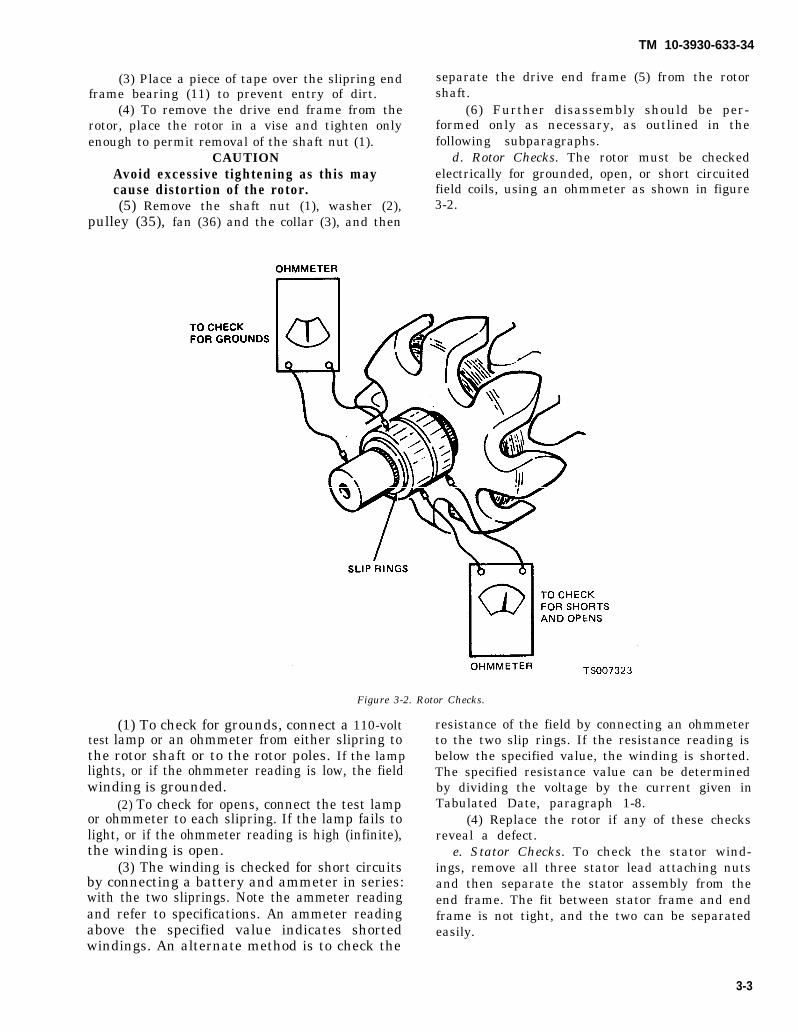
TM 10-3930-633-34
(3) Place a piece of tape over the slipring endframe bearing (11) to prevent entry of dirt.
(4) To remove the drive end frame from therotor, place the rotor in a vise and tighten onlyenough to permit removal of the shaft nut (1).
CAUTIONAvoid excessive tightening as this maycause distortion of the rotor.(5) Remove the shaft nut (1), washer (2),
pulley (35), fan (36) and the collar (3), and then
separate the drive end frame (5) from the rotorshaft.
(6) Further disassembly should be per-formed only as necessary, as outlined in thefollowing subparagraphs.
d. Rotor Checks. The rotor must be checkedelectrically for grounded, open, or short circuitedfield coils, using an ohmmeter as shown in figure3-2.
Figure 3-2. Rotor Checks.
(1) To check for grounds, connect a 110-volttest lamp or an ohmmeter from either slipring tothe rotor shaft or to the rotor poles. If the lamplights, or if the ohmmeter reading is low, the fieldwinding is grounded.
(2) To check for opens, connect the test lampor ohmmeter to each slipring. If the lamp fails tolight, or if the ohmmeter reading is high (infinite),the winding is open.
(3) The winding is checked for short circuitsby connecting a battery and ammeter in series:with the two sliprings. Note the ammeter readingand refer to specifications. An ammeter readingabove the specified value indicates shortedwindings. An alternate method is to check the
resistance of the field by connecting an ohmmeterto the two slip rings. If the resistance reading isbelow the specified value, the winding is shorted.The specified resistance value can be determinedby dividing the voltage by the current given inTabulated Date, paragraph 1-8.
(4) Replace the rotor if any of these checksreveal a defect.
e. Stator Checks. To check the stator wind-ings, remove all three stator lead attaching nutsand then separate the stator assembly from theend frame. The fit between stator frame and endframe is not tight, and the two can be separatedeasily.
3-3
TM 10-3930-633-34
(1) The stator windings may be checked witha 110-volt test lamp or an ohmmeter. If the lamplights, or if the meter readings is low whenconnected from any stator lead to the frame, thewindings are grounded. If the lamp fails to light,or if meter reading is high when successivelyconnected between each pair of stator lead, thewindings are open.
(2) A short circuit in the stator windings isdifficult to locate wit bout laboratory testequipment due to the low resistance of thewindings. However, if all other electrical checksare normal and the generator fails to supply ratedoutput, shorted stator windings are indicated.
f. Diode Checks. One method of checkingdiodes is to use an ordinary ohmmeter. The lowestrange scale on the ohmmeter should be used andthe ohmmeter should have a 1 ½ volt cell. Todetermine the cell voltage, turn the selector to thelowest scale, and then connect the ohmmeterleads to a voltmeter. The voltmeter will indicatethe cell volt age,
(1) With the stator disconnected, check adiode in the heat sink by connecting one of theohmmeter leads to the heat sink, and the otherohmmeter lead to the diode lead, and notethe reading. Then reverse the ohmmeter leadconnections and note the reading. If bothreadings are very low, or if both readings are veryhigh, the diode is defective. A good diode will giveone low reading and one high reading. Check theother two diodes in the heat sink in the samemanner.
(2) To check a diode mounted in the endframe, connect one of the ohmmeter leads to theend frame, and the other ohmmeter lead to thediode lead and note the reading. Then reverse theohmmeter lead connections, and note the reading.If both readings are very low, or if both readingsare very high, the diode is defective. A good diodewill give one low reading and one high reading.Check the other two diodes in the end frame in thesame manner.
g. Diode Replacement.(1) Diodes are pressed into the end frame
and heat sink. To remove diodes, use a piece oftubing slightly larger than the diode to supportthe heat sink or end frame, while pressing out theold diode.
(2) When pressing in a new diode, use a pieceof thin-wall tubing that will contact only the outerrim of the diode, to press the diodes in place.Support the heat sink and end frame with a largerpiece of tubing as before.
(3) Positive diodes are marked with redprinting, negative diodes with black, If all diodes
are replaced, be sure that positive diodes areinstalled in heat sink and negative diodes in-stalled in end frame.
CAUTIONDo not strike any of the diodes whileremoving. Shock may cause damage tothe other good diodes.
h. Slipring Servicing.(1) If the springs are dirty, they may be
cleaned and finished with 400 grain or finerpolishing cloth. Spin the rotor in a lathe, orotherwise spin the rotor, and hold the polishingcloth against the sliprings until they are clean.
CAUTIONThe rotor must be rotated in order thatsliprings will be cleaned evenly. Cleaningthe sliprings by hand without spinningthe rotor may result in flat spots on thesliprings, causing brush noise.(2) Sliprings which are rough or out-of-round
should be trued in a lathe to .002 inch maximumindicator reading. Remove only enough materialto make the rings smooth and round. Finish with400 grain or finer polishing cloth and blow awayall dust.
i. Bearing Replacement and Lubrication,(1) The bearing in the drive end frame can be
removed by detaching the retainer plate screwsand then pressing the bearing from the end frame.If the bearing is in satisfactory condition, it maybe re-used, and it should be filled one-quarter fullwith special grade ball bearing lubricant beforereassembly.
CAUTIONDo not overfill, as this may cause thebearing to overheat.(2) To install a new bearing, press in with a
tube or collar that just fits over the outer race. Itis recommended that a new retainer plate beinstalled if the felt seal in the retainer plate ishardened or excessively worn.
(3) The bearing in the slipring end frameshould be replaced if its grease supply isexhausted. No attempt should be made torelubricate and re-use the bearing. To remove thebearing from the slipring end frame, press outwith a tube or collar that just fits inside the endframe housing. Press from the outside of thehousing towards the inside.
(4) To install a new bearing, place a flat plateover the bearing and press in from the outsidetowards the inside of the frame until the bearingis flush with the outside of the end frame. Supportthe inside of the frame with a hollow cylinder toprevent breakage of the end frame. Use extreme
3-4

TM 10-3930-633-34
care to avoid misalignment or otherwise placingundue stress on the bearing.
(5) Saturate the felt seal with S.A.E. 20 oil,and then reassemble the felt seal and steelretainer.
j. Brush Replacement.(1) When the slipring end frame assembly is
separated from the rotor and drive end frameassembly, the brushes will fall down onto theshaft and come in contact with the lubricant. Ifthe brushes are to be re-used, they must bethoroughly cleaned with a soft dry cloth. Also,the shaft must be thoroughly cleaned beforereassembly.
(2) The brush springs should be inspectedfor any evidence of damage or corrosion. If thereis any doubt as to the condition of the brushsprings, they should be replaced.
(3) To install new brushes, remove the brushholder assembly from the end frame by detachingthe two brush holder assembly screws. Install thesprings and brushes into the brush holder, andinsert a straight wire or pin into the holes at thebottom of the holder to retain the brushes. Then
attach the brush holder assembly onto the endframe, noting carefully the proper stack-up ofparts as shown in figure 3-3. Allow the straightwire to protrude through the hole in the endframe.
Figure 3-3. Brush Holder Assembly.
k. Heat Sink Replacement. The heat sink maybe replaced by removing the “BAT” and “GRD”terminals from the end frame, and the screwattaching the condenser lead to the heat sink.During reassembly, note carefully the properstack-up of parts as shown in figure 3-4.
Figure 3-4. Heat Sink,
l. Reassembly. Reassemble the alternator as remove tape over the bearingshown in the exploded view (fig. 3-1). Note the sure shaft is perfectly clean.following procedures:
(1) Hold rotor with hex key wrench in end ofshaft and tighten pulley nut to 60 ft/lbs. If pulleyis held in vise and excessive pressure is appliedagainst rotor, the assembly may becomedistorted.
(2) When installing slipring end frameassembly to rotor and drive end frame assembly,
and shaft. Make
(3) Insert a straight wire as previouslymentioned through holes in brush holder and endframe to retain the brushes. Remove the wireafter the a.c. generator has been completelyassembled. The brushes will then drop into placeon sliprings.
m. Installation and Testing. Refer to TM 10-3930-633-12 for installation and testingprocedures.
3-5
TM 10-3930-633-34
Section II. STARTER
3-5. GeneralThe starter is a 12-volt motor that has the
solenoid mounted on the starter housing. Thesolenoid is energized when the starter relaycontacts are closed. This action engages thestarter drive with the flywheel ring gear, startingthe engine. An overrunning clutch in the driveprotects the starter from excessive speed whenthe engine starts. The starter current flowsthrough the solenoid energizing coil until thesolenoid plunger is at the end of its travel. Theplunger then closes a set of contacts that by-passthe energizing coil, letting the holding coil keepthe starter drive engaged.
3-6. Starter Repaira. Removal. Refer to TM 10-3930-633-12 for
complete removal instructions.
b. Disassembly. Refer to figure 3-5 for partsidentification, and proceed as follows, aftercleaning the outside of the starter thoroughly.
(1) Disconnect the field coil connections fromthe solenoid motor terminal.
(2) Remove the through bolts (15).(3) Remove the commutator end plate (16)
and field frame assembly.(4) Remove the armature assembly (22) from
the drive housing (24). It will be necessary toremove the solenoid (5) and shift lever assembly(13) from the drive housing before removing thearmature assembly.
(5) Remove thearmature shaft.
thrust collar (19) from the
3-6

TM 10-3930-633-34
1. Screw2. Lockwasher3. Lockwasher4. Field lead screw5. Solenoid6. Screw7. Plunger spring8. Plunger9. Switch seal
10. Bolt11. Washer12. Nut13. Lever14. Pivot pin15. Through bolt16. Commutator end plate
17.18.19.20.21.22.23.24.25.26.27.28.29.30.31.
Dowel pinDrive pinion assemblyCollarRetaining ringCollarArmatureThrust washerDrive end housingBushingPole shoe screwPole shoeField coilsGrommetBrush support setBrush set
Figure 3-5. Starter Assembly
3-7
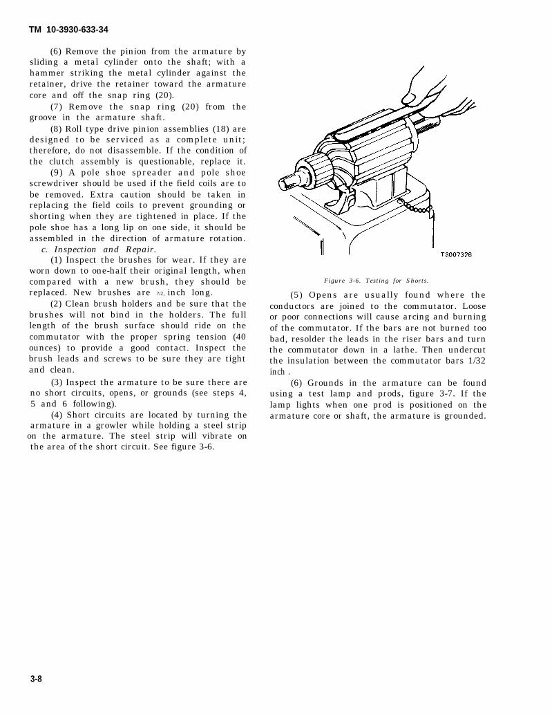
TM 10-3930-633-34
(6) Remove the pinion from the armature bysliding a metal cylinder onto the shaft; with ahammer striking the metal cylinder against theretainer, drive the retainer toward the armaturecore and off the snap ring (20).
(7) Remove the snap ring (20) from thegroove in the armature shaft.
(8) Roll type drive pinion assemblies (18) aredesigned to be serviced as a complete unit;therefore, do not disassemble. If the condition ofthe clutch assembly is questionable, replace it.
(9) A pole shoe spreader and pole shoescrewdriver should be used if the field coils are tobe removed. Extra caution should be taken inreplacing the field coils to prevent grounding orshorting when they are tightened in place. If thepole shoe has a long lip on one side, it should beassembled in the direction of armature rotation.
c. Inspection and Repair.(1) Inspect the brushes for wear. If they are
worn down to one-half their original length, whencompared with a new brush, they should bereplaced. New brushes are ?/2, inch long.
(2) Clean brush holders and be sure that thebrushes will not bind in the holders. The fulllength of the brush surface should ride on thecommutator with the proper spring tension (40ounces) to provide a good contact. Inspect thebrush leads and screws to be sure they are tightand clean.
(3) Inspect the armature to be sure there areno short circuits, opens, or grounds (see steps 4,5 and 6 following).
(4) Short circuits are located by turning thearmature in a growler while holding a steel strip
on the armature. The steel strip will vibrate onthe area of the short circuit. See figure 3-6.
Figure 3-6. Testing for Shorts.
(5) Opens are usually found where theconductors are joined to the commutator. Looseor poor connections will cause arcing and burningof the commutator. If the bars are not burned toobad, resolder the leads in the riser bars and turnthe commutator down in a lathe. Then undercutthe insulation between the commutator bars 1/32inch .
(6) Grounds in the armature can be foundusing a test lamp and prods, figure 3-7. If thelamp lights when one prod is positioned on thearmature core or shaft, the armature is grounded.
3-8

TM 10-3930-633-34
Figure 3-7. Testing for Grounds.
(7) Check field coils with a 12-volt test lampas outlined in steps 8 and 9.
(8) With the field coil ground disconnected,position one test prod on the field frame and theother to the field connector. If the lamp lights, thefield coils are grounded and must either bereplaced or repaired.
(9) If the test lamp does not light when theprods are connected to the ends of coil leads, thefield coils are open.
d. Reassembly. Refer to figure 3-5.(1) Place the drive pinion assembly (18) on
the armature shaft.(2) To aid in reinstalling the snap ring (20)
and collar (21 ) on the armature shaft, proceed asfollows. Place the collar (21 ) on the armatureshaft with the cupped surface facing the snap ringgroove.
(3) Place the snap ring (20) on the end of theshaft. With a piece of wood on top of ring, forcethe ring over the shaft with a light hammer blow,then slide the ring down into the groove.
(4) To force the retainer over the snap ring,place a suitable washer over the shaft and squeezethe retainer and washer together with pliers.
(5) Remove the washer.(6) Lubricate bearing of drive housing (24)
with silicon grease and install armature and driveassembly in housing.
CAUTIONDo not lubricate solenoid plunger orsolenoid cylinder.(7) Install return spring (7) on solenoid
plunger (8) and insert plunger into solenoidcylinder. Apply sealing compound on both sidesof solenoid flange where it extends between drivehousing and field frame. Attach plunger to shiftlever (13) with fulcrum pin (14). Fasten solenoidto drive housing with two mounting screws (6).
(8) If field coils were removed from fieldframe, position coils of replacement field coilassembly (28) on pole shoes and mount each poleshoe (27) in field frame with a pole shoe screw(26). Use care in tightening screws to avoiddistortion of parts. Be certain that screws aresecurely tightened. Insert ends of field coil leadsthrough rubber grommet in field frame.
(9) Position field frame assembly over ar-mature assembly so that its down pin (17)engages the hole in drive housing. Use care toprevent damage to brushes and brush holders.Make sure that brushes (31) are properly seatedon commutator.
(10) Install leather thrust washer (23) oncommutator end of armature assembly. Lubricatebearing in commutator end frame with silicongrease and position end frame to field frame sothat armature shaft enters bearing. Secure fieldframe and end frame to drive housing with twothrough bolts (15). Connect field leads to motorterminal of solenoid with screw (4).
e. Installation and Testing. Refer to TM 10-3930-633-12 for procedures covering installationand testing of the starter assembly.
Section III. IGNITION DISTRIBUTOR
3-7. General the ignition timing at higher engine speeds orThe distributor is equipped with both vacuum heavy engine loadings to provide the correct
and centrifugal advance units. The vacuum ignition timing for maximum engine performance.advance governs the ignition timing (spark The advance mechanisms are independentlyadvance) during low engine speeds (RPM ) or low operated,engine loadings, The centrifugal advance, in a. Centrifugal Advance. The centrifugal ad-combination with the vacuum advance, controls vance mechanism (fig. 3-8) is located below the
3-9
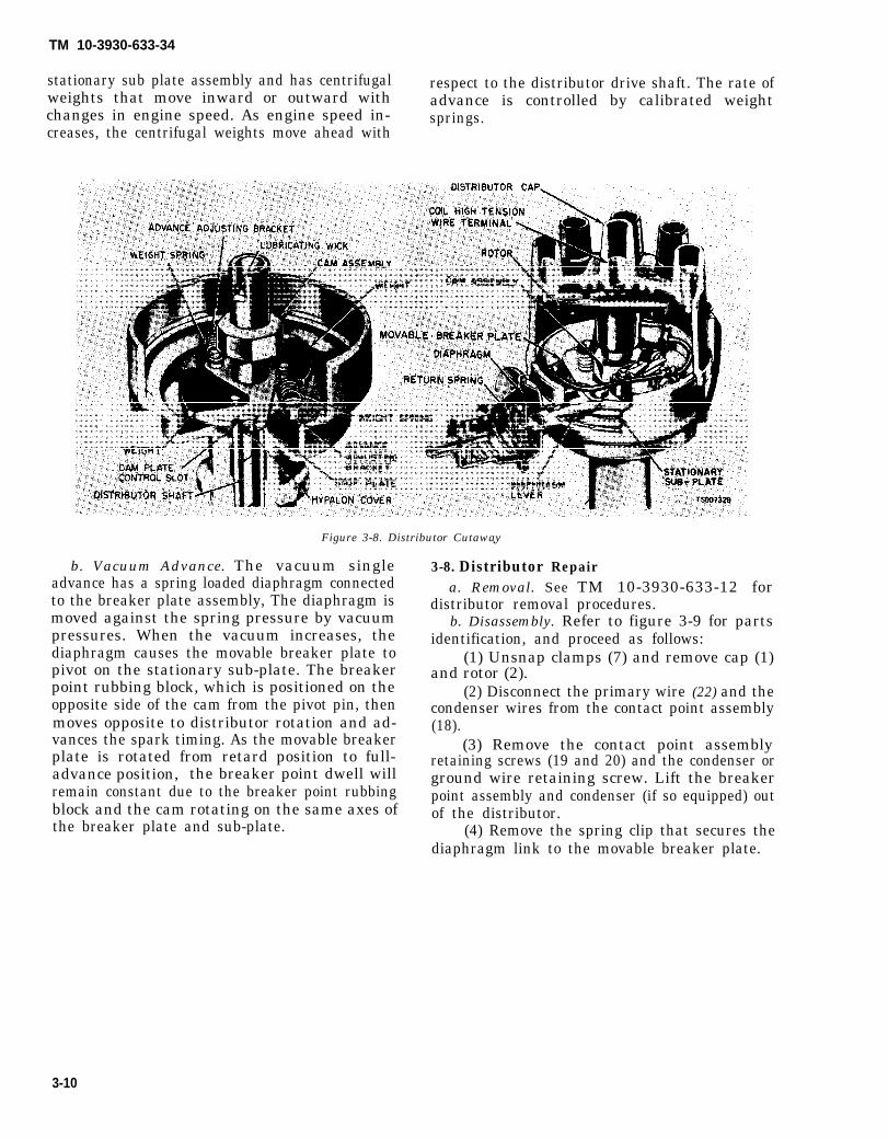
TM 10-3930-633-34
stationary sub plate assembly and has centrifugal respect to the distributor drive shaft. The rate ofweights that move inward or outward with advance is controlled by calibrated weightchanges in engine speed. As engine speed in- springs.creases, the centrifugal weights move ahead with
Figure 3-8. Distributor Cutaway
b. Vacuum Advance. The vacuum singleadvance has a spring loaded diaphragm connectedto the breaker plate assembly, The diaphragm ismoved against the spring pressure by vacuumpressures. When the vacuum increases, thediaphragm causes the movable breaker plate topivot on the stationary sub-plate. The breakerpoint rubbing block, which is positioned on theopposite side of the cam from the pivot pin, thenmoves opposite to distributor rotation and ad-vances the spark timing. As the movable breakerplate is rotated from retard position to full-advance position, the breaker point dwell willremain constant due to the breaker point rubbingblock and the cam rotating on the same axes ofthe breaker plate and sub-plate.
.
3-8. Distributor Repaira. Removal. See TM 10-3930-633-12 for
distributor removal procedures.b. Disassembly. Refer to figure 3-9 for parts
identification, and proceed as follows:(1) Unsnap clamps (7) and remove cap (1)
and rotor (2).(2) Disconnect the primary wire (22) and the
condenser wires from the contact point assembly(18).
(3) Remove the contact point assemblyretaining screws (19 and 20) and the condenser orground wire retaining screw. Lift the breakerpoint assembly and condenser (if so equipped) outof the distributor.
(4) Remove the spring clip that secures thediaphragm link to the movable breaker plate.
3-10

TM 10-3930-633-34
10. Gasket11. Stop12. Spring13. Diaphragm assembly14. Screw15. Washer16. Ground wire17. Condenser18. Contact point set
19. Screw20. Screw21. Washer22. Primary wire23. Nut24. Washer25. Spring clip26. Movable breaker plate27. Stationary sub-plate
28. Retainer29. Cam30. Thrust washer31. Oiler32. Springs33. Weights34. Shaft assembly35. Bushing
1. Distributor cap2. Rotor3. Gear4. Pin5. Spacer6. Seal ring7. Clamp8. Pin9. Vacuum connector
Figure 3-9. Distributor Assembly.
3-11
TM 10-3930-633-34
(5) Remove the diaphragm retaining screws(14) and slide the diaphragm out of thedistributor.
(6) Working from the inside of thedistributor, pull the primary wire (22) through theopening in the distributor.
(7) Remove the spring clip (26) the flatwasher and the spring washer securing thebreaker plate (26) to the sub-plate (27).
(8) Remove the sub-plate retaining screwsand lift both plates (26 and 27) out of thedistributor,
(9) Mark one of the distributor weightsprings and its brackets. Also mark one of theweights and its pivot pin.
(10) Carefully unhook and remove theweight springs (32).
(11 ) Lift the lubricating wick from the camassembly. Remove the cam retainer (28). Lift thecam assembly off the distributor shaft. Removethe thrust washer (30),
(12) Remove the weight retainers and lift theweights (33) out of the distributor.
(13) Remove the distributor cap clamps (7).(14) If the gear and shaft are to be used
again, mark the gear and the shaft so that the pinholes can be easily aligned for assembly. Removethe gear roll pin (4).
(15) Invert the distributor and place it on asupport plate in a position that will allow thedistributor shaft to clear the support plate andpress the shaft out of the gear and the distributorhousing.
(16) Remove the oil filler cap and the feltwick (31).
c. Inspection.(1) Check distributor shaft and bushing for
signs of wear. If wear is evident, the entiredistributor should be replaced.
(2) Check gear carefully for worn or damagedteeth. Replace a worn gear.
(3) Check breaker and sub-plates to makesure they fit properly and work without stickingor binding.
(4) Use new point set and condenser, rotor,and distributor cap when reassembling thedistributor.
(5) Replace primary wire if it is burned,chafed, or corroded.
d. Reassembly. See figure 3-9.(1) Oil the shaft and slide it into the
distributor body.(2) Place the assembly in a vise or press and
install gear (3) on shaft using a piece of tubingsized to slide over shaft and bear against gear
hub. Press gear on until hole in gear aligns withhole in shaft for installation of pin (4).
(3) Check the shaft end play with feeler gageplaced between the collar and the base of thedistributor. If the end play is not within 0.003 to0.010 inch, replace the shaft and gear.
(4) Remove the distributor from the press.Install the gear retaining pin (4).
(5) Position the distributor in a vise. Fill thegrooves in the weight pivot pins with adistributor cam lubricant.
(6) Position the weights (33) in thedistributor (the marked weight is placed on themarked pivot pin) and install the weightretainers.
(7) Place the thrust washer (30) on the shaft.(8) Fill the grooves in the upper portion of
the distributor shaft with distributor camlubricant.
(9) Install the cam assembly (29), Be surethat the marked spring bracket on the camassembly is near the marked spring bracket onthe stop plate.
(10) If a new cam assembly is being in-stalled, make sure that the hypalon covered stopis in the correct cam plate stop, This can be doneby measuring the length of the slot used on theold cam and by using the corresponding slot onthe new cam. Some of the cams will have thelength of the slot in degrees stamped near theslot. If the wrong slot is used, an incorrectmaximum advance will be obtained.
(11) Place a light film of distributor camlubricant on the distributor cam lobes. Install theretainer and the wick. Saturate the wick withSAE 10W engine oil.
(12) Install the weight springs (32). Be surethat the marked spring is attached to the markedspring brackets.
(13) Place the breaker plate (26) in positionon the sub-plate (27).
(14) Install the spring washer, the flatwasher, and the spring clip that secures thebreaker plate to the sub-plate.
(15) Install the sub-plate hold-down screws(the ground wire should be under the sub-platehold-down screw near the primary wire opening inthe distributor).
(16) Working from the inside of thedistributor, push the primary wire (22) throughthe opening in the distributor.
(17) Slide the diaphragm (18) into theopening in the distributor and place the link in itsposition.
(18) Install the spring clip that secures the
3-12
TM 10-3930-633-34
diaphragm link to the movable breaker plate and (21 ) Install the rotor (2) and the distributorinstall the diaphragm retaining screws (14). cap (1).
(19) Place the contact point assembly (18) (22) Fill the oiler (31) with about 40 drops ofand the condenser (17) in position and install the oil .retaining screws (19, 20 and 21). Be sure to place e. Installation and Adjustment. Refer to TMthe ground wire (16) under the condenser 10-3930-633-12 for procedures on installing theretaining screws. distributor, adjusting and aligning contact
(20) Connect the primary wire (22) and the points, and adjusting ignition timing.condenser lead to the contact point assembly.
3-13

TM 10-3930-633-34
CHAPTER 4
REPAIR OF FUEL SYSTEM
4-1. General with a disposable element cartridge, the single-a. The fuel system consists of the fuel tank (17 barrel down-draft carburetor, dry-type air
gallon capacity), mounted to the right side of the cleaner, velocity governor, and the necessaryframe, a mechanical, diaphragm-type pump lines and fittings to complete the system. Refer todriven off the engine and protected by a fuel filter figure 4-1 for details of the fuel system.
4-1

Figure 4-1.
TM 10-3930-633-34
4-2
b. A variable resistance type of float and senderunit is mounted in the fuel tank and connected to afuel gage on the instrument panel. The fuel filler cap isa safety type with an integral strainer.
4-2. Fuel Tank Repaira. Removal. Refer to TM 10-3930-633-12,
paragraph 4-47.
The fuel tank must be thoroughly drainedand FLUSHED before any cutting orwelding is done on the tank surfaces. Fillthe tank completely with hot water todrive out all vapors. Drain water andblow out tank with compressed air orCO2. After welding, fill tank with waterand check for leaks. Drain tank, steamclean and dry thoroughly beforereinstallation.
TM 10-3930-633-34
b. Repair. Prior to repair of the fuel tank, removecombustibles from interior of tanks in accordance withTB 750-1047 (Elimination of Combustibles fromInteriors of Metal or Plastic Gasoline and Diesel FuelTanks).
c. Installation. Refer to TM 10-3930-633-12,paragraph 4-47.
4-3. Carburetor Problem DiagnosisParagraph 4-3 has been rescinded.
4-4. Carburetor DescriptionParagraph 4-4 and Figure 4-2 have been
rescinded,
4-5. Carburetor RepairRefer to TM 10-3930-633-12,
(Pages 4-4 through 4-6 have been rescinded.)
Change 1 4-3


TM 10-3930-633-34
CHAPTER 5
REPAIR OF COOLING SYSTEM
5-1. GeneralThe cooling system is of the pressurized type
and utilizes a tube and fin type radiator. Thecoolant is drawn from the bottom of the radiatorby the water pump, which circulates the coolantthrough the engine block. As the coolant entersthe block, it travels through cored passages tocool the entire length of each cylinder wall. Uponreaching the rear of the cylinder block, the coolantis directed upward into the cylinder head where itcools the combustion chambers, valves and valveseats on its return to the front of the engine.
5-2. Cooling System Testa. General. The cooling system test as
outlined in the following paragraph will revealsuch problems as blown gaskets, internal orexternal system leakage, or pressure capmalfunction. The type of pressure tester usedshould be fitted with a gage, and be adaptable toa hose connection.
b. Procedure.(1) Shut off the engine. To prevent loss of
coolant and to avoid the danger of being burned,place a cloth over the cap and rotate the capslowly counterclockwise to first stop and allowpressure to escape completely. Then turn capagain slowly counterclockwise to remove.
(2) After the cooling system pressure hasbeen released, remove the radiator cap, wet therubber sealing surface and reinstall cap tightly onthe radiator.
(3) Disconnect the electrical connector fromthe engine temperature sending unit and removethe temperature sending unit from the manifold.With the radiator cap installed, only a smallamount of coolant will be lost when the sendingunit is removed.
(4) Install an adapter fitting (3/8 N. P. T.male thread on one end, and a hose connection onthe other end to accommodate the tester hose)tightly into the intake manifold or cylinder headin place of the sending unit.
(5) Remove the radiator overflow hose fromthe retainer clips. Make sure the hose is firmlyinstalled on the radiator overflow tube and is ingood condition. Insert the free end of the overflowhose into a container of water.
(6) Attach the pressure pump and gage to
the adapter fitting and pressurize the coolingsystem until bubbles are observed in the watercontainer. Discontinue pumping when bubblesappear.
(7) When the bubbles cease, read thepressure gage. The gage reading is the pressurerelief of the cap and should be withinspecifications. If the pressure reading exceeds thespecified limit, replace the radiator cap.
(8) If bubbles continue and the pressuredrops below 10 PSI, the radiator cap is notholding pressure. Release pressure and wash capin clean water to dislodge any foreign matter fromthe valves. Check the rubber sealing surface ofthe cap and also the cap sealing surface in theradiator neck. Inspect the cam lock flanges onboth sides of the filler neck for maximum capengagement.
(9) Recheck the cooling system as outlined insteps 6 and 7. If the cap still does not holdpressure, the cap is damaged and must bereplaced. Recheck system after a new cap is in-stalled to assure that the system will now holdpressure.
(10) If the bubbles in the water containercease and radiator cap is within pressurespecifications, observe gage reading for ap-proximately two minutes. Pressure should notdrop during this time.
(11) If pressure drops, check for leaks at theengine to heater core hoses, engine to radiatorhoses, by-pass hose, water valve hose (A/Cequipped), thermostat housing gasket, etc. Anyleaks which are found must be corrected and thesystem rechecked.
(12) If the system holds pressure, removethe radiator cap to release the pressure, thenreinstall the cap.
(13) Remove the adapter from the manifoldor cylinder head and reinstall the temperaturesending unit. Check coolant level and replenish ifnecessary with the correct coolant solution.
5-3. Radiatora. Maintenance. Maintenance of the radiator
consists of keeping the exterior of the radiatorcore clean, the interior free from rust and scale,and the radiator free from leaks. Check thecooling system fluid level and for leaks at each
5-1

TM 10-3930-633-34
scheduled maintenance interval. The exterior ofthe radiator core should be cleaned and theradiator inspected for leaks each 1000 operatinghours of normal service of the vehicle. Cleaningshould be performed by blowing out with airstream or water stream directed from the rear ofthe radiator. Visual inspection is not sufficient asthe accumulation of small particles of foreignmaterial on core surfaces can restrict coolingwithout closing the core openings.
b. Leakage. Radiator leakage occasionallyresults from corrosion perforation of the metalbut most leakage results from mechanical failureof soldered joints when too much strain has beenput on the joint. Fractures occur most often at thejoint where the radiator inlet and outlet pipes areattached to the tanks. When the seams break, theentire soldered joint is exposed and can corrode,but breakage rather than corrosion is the primarycause of seam leakage. Examine the radiatorcarefully for leaks before and after cleaning.Cleaning may uncover points of leakage alreadyexisting but plugged with rust. White, rusty, orcolored leakage stains indicate previous radiatorleakage. These spots may not be damp if wateronly or methyl-alcohol-base antifreeze is in thecooling system since such coolants evaporatereadily. An ethylene-glycol-base antifreeze shows
up existing leaks as it does not evaporate. Theradiator may be tested for leaks by using theprocedure outlined in the previous paragraph.
5-4. Radiator Repaira. Removal and Installation. Refer to TM 10-
3930-633-12.b. Filler Neck. If the seating surface of the
radiator cap is corroded or scored, use a com-mercially available reseating tool to clean up thesurface, or use emery cloth or a small grindingwheel. Make certain the locking ears on the lip ofthe neck are not bent or worn.
c. Overflow Pipe. If the overflow pipe isdented or clogged, the pressure caused by ob-struction may cause damage to the radiator orhose connections in the cooling system. T oremove clogging material, run a flexible wirethrough the overflow pipe.
d. Radiator Core. Steam clean the radiatorcore thoroughly to remove dirt and debris. Directsteam from engine side of core. Straighten anybent fins using needle-nose pliers. Leakage of aminor nature at core and header tank joints maybe repaired by soldering; however, a badlycorroded, leaking or a punctured core must bereplaced.
5-2

TM 10-3930-633-34
CHAPTER 6
REPAIR OF ENGINE
Section I. DESCRIPTION
6-1. GeneralThe engine is a six cylinder, in-line, overhead
valve design. Engine displacement is 300 cubicinches. The engine is equipped with a 12-voltelectrical system, including a coil and distributortype ignition system, starting system, andbattery charging system with alternator. The fuelsystem includes the mechanically operated fuelpump and single throat, down-draft carburetor.Description of these systems is provided underseparate chapter headings in this manual.
6-2. Cylinder HeadThe cylinder head carries the valves, rocker
arms and springs, manifold assemblies, coolantoutlet, and thermostat. Valve guides are integralwith the head. Refer to Section IV for cylinderhead repairs.
6-3. Valvesa. Valve Timing. Valve timing and operation
is accomplished by the camshaft, lifters,pushrods, and rocker arms. The camshaft isdriven from the crankshaft by a timing chain andsprockets, enclosed in a cover on the front of theengine. The camshaft is supported by four steel-backed babbitt bearings pressed into the block.Camshaft thrust is controlled by a thrust washerlocated between the camshaft sprocket and thefront camshaft journal. An integral eccentric onthe camshaft operates the fuel pump.
b. Valve Train. The lifters are of the ex-panding hydraulic type, where oil under pressureis used to expand the lifter to remove all valvelash from the mechanism. Pushrods are tubular,steel, with oil-cushioned sockets. Intake andexhaust valve assemblies are of the rotating type.
6-4. Cylinder Blocka. The cylinders are numbered from 1 to 6
starting at the front of the engine. The firingorder is 1-5-3-6-2-4. ‘The distributor is located on
the left side of the engine, toward the front. Thedistributor is gear driven from the camshaft and,in turn drives the oil pump through an in-termediate drive shaft.
b. The crankshaft is supported by four mainbearings, with the thrust being controlled byflanges on the number 3 main bearing. Thepistons are tin-plated aluminum alloy and havetwo compression rings and one oil control ring.
6-5. Lubrication Systema. The lubrication system is a positive pressure
system and is supplied by a rotor type pumpsubmerged in the crankcase sump. A springloaded relief valve in the pump limits themaximum pressure of the system. Oil relieved bythe valve is directed back to the intake side of thepump.
b. All the oil discharged by the pump passesthrough a full flow type filter before entering theengine. The filter has an integral bypass valveand mounting gasket. The by-pass valve permitsoil to by-pass the filter if it becomes clogged withimpurities. thereby maintaining an emergencysupply of oil to the engine at all times. An an-tidrain back diaphragm prevents the reverse flowcf oil from the upper engine parts whenever theengine is stopped.
c. From the filter, the oil flows into the main oilgallery, which supplies oil to all the camshaft andmain bearings through a drilled passage in eachbearing web. The timing gears receive oil througha squirt hole in the block face. Oil slingers preventleakage by directing oil away from the crankshaftfront. and rear oil seals.
d. Cylinder walls, pistons, and piston pins arelubricated through a drilled passage in eachconnecting rod journal of the crankshaft. Drilledpassages in the block supply pressurized oil to thehydraulic lifters, pushrods and rocker arms. Theoil in the pushrod chamber drains back into thepan through cored openings in the cylinder block.
6-1

TM 10-3930-633-34
Section Il. ENGINE TEST AND PERFORMANCE ANALYSIS
6-6. GeneralThe performance checks and tests outlined in
this section will aid in diagnosing engine con-dition and determine the extent and location ofrepairs required to bring the engine up to aserviceable condition.
6-7. Intake Manifold Vacuum Testa. Test Procedures. A manifold vacuum test
aids in determining the condition of an engine andin helping to locate the cause of poor engineperformance. To check manifold vacuum:
(1) Operate the engine for a minimum of 30minutes at 1200 RPM or until the engine is atnormal operating temperature.
(2) Connect an accurate, sensitive vacuumgage to the intake manifold vacuum line or on thefitting in the intake manifold. (See figure 6-1.)
(3) Operate the engine at recommended idleRPM, with the transmission selector lever inneutral.
(4) Check the vacuum reading on the gage,and compare with table 6-1.
b. Test Results. Manifold vacuum is affectedby the carburetor adjustment, valve timing,valve lash, ignition timing, condition of thevalves, cylinder compression, condition of thepositive crankcase ventilation system, andleakage of the intake manifold, carburetor,carburetor spacer or cylinder head gaskets.
c. Readings. Because abnormal gage readingsmay indicate that more than one of the abovefactors are at fault, exercise caution in analyzingan abnormal reading. For example, if the vacuumis low, the correction of one item may increase thevacuum enough to indicate that the trouble hasbeen corrected. It is important, therefore, thateach cause of an abnormal reading be investigatedand further tests conducted, where necessary, inorder to arrive at the correct diagnosis of thetrouble.
6-8. Compression Testa. General. A cylinder compression test aids
in determing the condition of the valves, ringsand head gasket. This test should always beperformed at the recommended intervals to helpdetermine if any major engine repairs arenecessary.
Figure 6-1. Manifold Vacuum Test Connection.
6-2

TM 10-3930-633-34
Table 6-1. Manifold Vacuum Readings.
Gage Reading (inches Hg) Engine Condition(See footnote at end of Table)
17 or more. Normal.
Low and steady. Loss of power in all cylinders caused by late ignition or valve timing, or loss ofcompression due to leakage mound the piston rings.
Very low. Manifold. carburetor or cylinder head gasket leak.
Needle fluctuates steadily as speed increases. A partial or complete loss of power in one or more cylinders caused by: aleaking valve, cylinder head or intake manifold gasket leak, a defect in theignition system or a weak valve spring.
Gradual drop in reading at engine idle. Excessive back pressure in the exhaust system.
Intermittent fluctuation._ -
An occasional loss of power possibly caused by a defect in the ignition systemor a sticking valve.
Slow fluctuation or drifting of the needle. Improper idle mixture adjustment, or carburetor spacer or intake manifoldgasket leak.
NOTE
Allowance should be made for the effect of altitude on the gage reading. The engine vacuum will decrease with an increase in altitude.
b. Procedure.(1) Be sure the battery is good. Operate the
engine until normal operating temperature isreached. Turn the ignition switch off. Loosen thespark plugs, blow out any dirt in the spark plugwells, then remove the plugs.
(2) Set the carburetor throttle and chokeplates in the wide open position.
(3) Install a compression gage in No. 1cylinder.
(4) Crank the engine (with the ignitionswitch off) at least five (5) pumping strokes andrecord the highest reading indicated. Note theapproximate number of compression strokesrequired to obtain the highest reading..
(5) Repeat the check on each cylindercranking the engine approximately the samenumber of compression strokes.
c. Results. T h e indicated compressionpressures are considered normal if the lowestreading cylinder is within 75 percent of thehighest. Refer to table 6-2 for pressure limitsbetween cylinders. Variations exceeding 75percent implies an improperly seated valve orworn or broken piston rings.
Table 6-2. Compression Test Pressure Limits.Maximum Minimum
PSI PSI
186 . . . . . . . . . . . . . . . . . . . . . . . . . . . . . . . . . . . . . . ...140188 . . . . . . . . . . . . . . . . . . . . . . . . . . . . . . . . . . . . . . ...141190 . . . . . . . . . . . . . . . . . . . . . . . . . . . . . . . . . . . . . . ...142
Table 6-2. Compression Test Pressure Limits – Continued
Maximum MinimumPSI PSI
d. Diagnosis. If one, or more, cylinders readlow, squirt approximately one (1) tablespoon ofengine oil on top of the pistons in the low readingcylinders. Repeat compression pressure check onthese cylinders.
(1) If compression improves considerably,the piston rings are at fault.
(2) If compression does not improve, valvesare sticking or seating poorly.
(3) If two adjacent cylinders indicate lowcompression pressures and squirting oil on thepistons does not increase the compression, thecause may be a cylinder head gasket leak betweenthe cylinders. Engine oil and/or coolant in thecylinders could result from this problem.
6-3
TM 10-3930-633-34
6-9. General
Section Ill. ENGINE OVERHAUL
disassembly of the engine. Many of theEngine overhaul is the orderly and systematic
disassembly and reassembly of the engine, andrequired replacement of all parts found to bedefective, or worn, or otherwise substandard,during the overhaul procedure. While overhauldoes not necessarily return the engine to a likenew condition, the procedure will result in acompletely serviceable engine.6-10. Disassembly
a. General. Review general maintenanceprocedures in Chapter 2, Section III, and refer tofigures 6-2 through 6-7, while performing
disassembly procedures given here are given inmore detail under the individual section headings(Section IV. Cylinder Head and Valves, etc.).
b. Procedure.(1) Remove the engine front support (1, fig.
6-2).(2) If available, install the engine on a work
stand such as that shown in figure 6-3. A stand ofthis type will simplify disassembly, as the engineblock can be turned to different positions as workproceeds.
6 - 4

TM 10-3930-633-34
1.2.3.4.5.6.7.8.9.
10.
SupportScrewUpper dampenerSpacerSpacerLower dampenerWasherS. crewLockwasherNut
11. Upper dampener12. Lower dampener13. Spacer14. Dampener15. Screw16. Cover17. Gasket18. Seal19. Screw
Figure 6-2. Engine Assembly.
20. Hose21. Clamp22. Tube23. Tee24. Connector25. Plug26. Gasket27. Screw28. Washer29. Oil pan
30. Gasket31. Gasket32. Gasket33. Gasket34. Screw35. Lockwasher36. Fan37. Hub38. Pulley
6-5
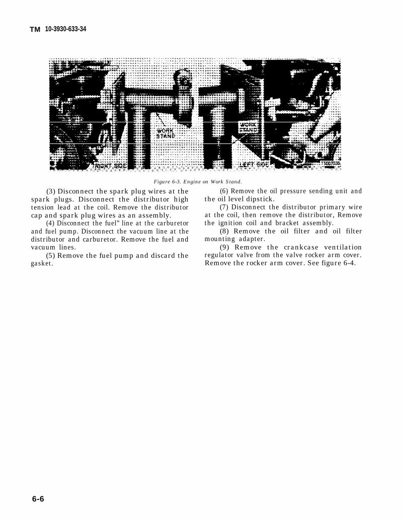
TM 10-3930-633-34
Figure 6-3. Engine on Work Stand.
(3) Disconnect the spark plug wires at thespark plugs. Disconnect the distributor hightension lead at the coil. Remove the distributorcap and spark plug wires as an assembly.
(4) Disconnect the fuel” line at the carburetorand fuel pump. Disconnect the vacuum line at thedistributor and carburetor. Remove the fuel andvacuum lines.
(5) Remove the fuel pump and discard thegasket.
(6) Remove the oil pressure sending unit andthe oil level dipstick.
(7) Disconnect the distributor primary wireat the coil, then remove the distributor, Removethe ignition coil and bracket assembly.
(8) Remove the oil filter and oil filtermounting adapter.
(9) Remove the crankcase ventilationregulator valve from the valve rocker arm cover.Remove the rocker arm cover. See figure 6-4.
6-6
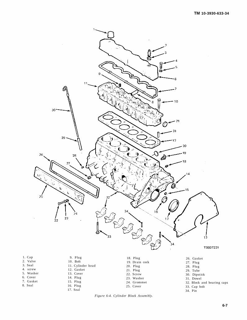
TM 10-3930-633-34
1. Cap2. Valve3. Seal4. screw5. Washer6. Cover7. Gasket8. Seal
9. Plug10. Bolt11. Cylinder head12. Gasket13. Cover14. Plug15. Plug16. Plug17. Seal
18. Plug19. Drain cock20. Plug21. Plug22. Screw23. Washer24. Grommet25. Cover
26. Gasket27. Plug28. Plug29. Tube30. Dipstick31. Dowel32. Block and bearing caps33. Cap bolt34. Pin
Figure 6-4. Cylinder Block Assembly.
6-7

TM 10-3930-633-34
(10) Loosen the rocker arm stud nuts, rotatethe rocker arms to one side and remove thepushrods in sequence. Place the pushrods in a
rack so they can be installed in the same locationfrom which they were removed. See figure 6-5.
1. Gear2. Plate3. Screw4. Lockwasher5. Spacer6. Key7. Camshaft8. Bushing9. Nut
10. Seat11. Rocker arm12. Stud
Figure 6-5. Camshaft and Value ‘Train,
13. Pushrod14. Tappet15. Lock16. Seat17. Seal18. Spring19. Valve20. Lock21. Seat.22. Seal23. Spring24. Valve
(11) Remove the valve pushrod cover. so they may be installed in the same bores fromRemove the valve lifters and place them in order which they were removed. See figure 6-6.
6-8
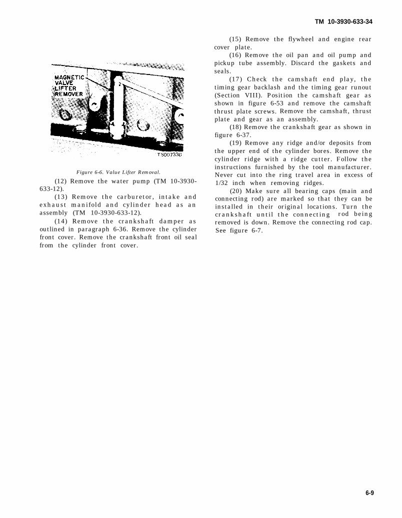
TM 10-3930-633-34
Figure 6-6. Value Lifter Removal.
(12) Remove the water pump (TM 10-3930-633-12).
(13) Remove the carburetor, intake andexhaust manifold and cylinder head as anassembly (TM 10-3930-633-12).
(14) Remove the crankshaft damper asoutlined in paragraph 6-36. Remove the cylinderfront cover. Remove the crankshaft front oil sealfrom the cylinder front cover.
(15) Remove the flywheel and engine rearcover plate.
(16) Remove the oil pan and oil pump andpickup tube assembly. Discard the gaskets andseals.
(17) Check the camshaft end play, thetiming gear backlash and the timing gear runout(Section VIII). Position the camshaft gear asshown in figure 6-53 and remove the camshaftthrust plate screws. Remove the camshaft, thrustplate and gear as an assembly.
(18) Remove the crankshaft gear as shown infigure 6-37.
(19) Remove any ridge and/or deposits fromthe upper end of the cylinder bores. Remove thecylinder ridge with a ridge cutter. Follow theinstructions furnished by the tool manufacturer.Never cut into the ring travel area in excess of1/32 inch when removing ridges.
(20) Make sure all bearing caps (main andconnecting rod) are marked so that they can beinstalled in their original locations. Turn thecrankshaft until the connecting rod beingremoved is down. Remove the connecting rod cap.See figure 6-7.
6-9
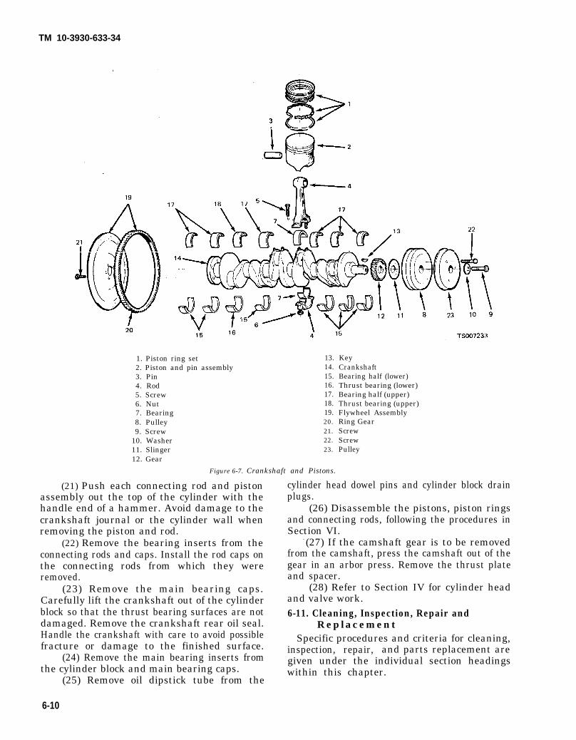
TM 10-3930-633-34
1. Piston ring set2. Piston and pin assembly3. Pin4. Rod5. Screw6. Nut7. Bearing8. Pulley9. Screw
10. Washer11. Slinger12. Gear
13.14.15.16.17.18.19.20.21.22.23.
Figure 6-7. Crankshaft and Pistons.
(21) Push each connecting rod and pistonassembly out the top of the cylinder with thehandle end of a hammer. Avoid damage to thecrankshaft journal or the cylinder wall whenremoving the piston and rod.
(22) Remove the bearing inserts from theconnecting rods and caps. Install the rod caps onthe connecting rods from which they wereremoved.
(23) Remove the main bearing caps.Carefully lift the crankshaft out of the cylinderblock so that the thrust bearing surfaces are notdamaged. Remove the crankshaft rear oil seal.Handle the crankshaft with care to avoid possiblefracture or damage to the finished surface.
(24) Remove the main bearing inserts fromthe cylinder block and main bearing caps.
(25) Remove oil dipstick tube from the
KeyCrankshaftBearing half (lower)Thrust bearing (lower)Bearing half (upper)Thrust bearing (upper)Flywheel AssemblyRing GearScrewScrewPulley
cylinder head dowel pins and cylinder block drainplugs.
(26) Disassemble the pistons, piston ringsand connecting rods, following the procedures inSection VI.
- (27) If the camshaft gear is to be removedfrom the camshaft, press the camshaft out of thegear in an arbor press. Remove the thrust plateand spacer.
(28) Refer to Section IV for cylinder headand valve work.6-11. Cleaning, Inspection, Repair and
ReplacementSpecific procedures and criteria for cleaning,
inspection, repair, and parts replacement aregiven under the individual section headingswithin this chapter.
6-10

6-12. Reassemblya. General. Certain specific procedures to be
followed during reassembly are detailed under thesection headings elsewhere in this chapter wherethe specific component or functional group repairinstructions are given. When this is the case, theappropriate section or paragraph is referenced inthe reassembly procedure. Refer to table 6-3 fortorque values.
b. Procedure(1) Invert the engine on the work stand,
Position new camshaft bearings in the cylinderblock, making sure that the oil holes in thebearing are aligned with those in the block. Pressthem in place. Be sure the camshaft front bearingis installed the specified distance below the frontface of the cylinder block. See table 6-7.
T M
(2) Oil the camshaft bearingapply Lubriplate or equivalent to
10-3930-633-34
journals andall the lobes.
Then carefully slide the camshaft through thebearings.
(3) If the camshaft gear was removed, installthe spacer, thrust plate and gear, using a toolsimilar to that shown in figure 6-55.
(4) Install the thrust plate screws and torqueto specifications.
(5) If the crankshaft main bearing journalshave been refinished to a definite undersize,install the correct undersize bearings. Be sure thebearing inserts and bearing bores are clean.
(6) Place the upper main bearing inserts inposition in the bore with the tang fitting in theslot provided.
Table 6-3. Engine Fasteners Torque Values
Item (Ft lb)Torque
Cylinder Head Bolts Step I... . . . . . . . . . . . . . . . . . ...50-55Cylinder Head Bolts Step 2........ . . . . . . . . . . . . . .. .. . . .60-65Cylinder Head Bolts Step 3 (see footnote at end of table) . . . . . . . . . . . . . . . . . . . . . . . . . . . . . . . . ...70-75Main Bearing Cap Bolts... . . . . . . . . . . . . . . . . ... . . . . .. .60-70Exhaust Manifold to Cylinder Head. . . . . . . . . . . . . . . . . . . . . . . ...23-28Intake to Exhaust Manifold . . . . . . . . . . .28-33Oil Pump to Cylinder Block . . . . . . . . . . . . . . . . . . . . . . . . . . . . . ...12-15Oil Pump Cover Plate . . . . . . . . . . . . . . ...9-15Oil Filter Center Bolt. . . . . . . . . . .. . . .. . . . . . . . ..20-25Flywheel to Crankshaft . . . . . . . . . . . . . . . . . . ...75-85Damper or Pulley to Crankshaft . . . . . . . ..130-150Water Pump to Cylinder Block or Front Cover . . . . . . . . . . . . . . . . . . .15-20Oil Pick-Up Tube to Oil Pump. .. . . . . . . . . . . . . . . .. . . . . . ...12-15Valve Rocker Arm Cover. . . . .. .. .. . . . . . . . . . . . .. . . . . .. . ..4-7Cylinder Front Cover . . . . . . . . . . . . . ...12-18Oil Pan to Cylinder Block . . . . . . . . . . . . . . . . . . . . . . . . . ...10-12Oil Pan Drain Plug. . . . . . . . . . . . .. . . . . .. .. . . .. .15-25Intake Manifold to Cylinder Head. . . . . . .. . . . . . . .. . . . .. . ..23-28Exhaust Manifold to Muffler Inlet Pipe . . . . . . . . . . . . ...25-30Valve Rocker Arm Stud Adjusting Nut Removal Torque
(Break-away ) counterclockwise . . . . . . . . . . . . . . . . . . . ...4.5-15Oil Filter Adapter to Cylinder Block . . . . . . . . . . . . . . . . . . . . . ...38-42Valve Pushrod Chamber Cover (in./lb) . . . . . . . . . . . . . . . . . . ...15-20Fuel Pump to Cylinder Block or Cylinder Front Cover . . . . . . . . . ...12-15Connecting Rod Nuts . . . . . . . . . . . . . . . . . . . . . . . . . . . . . ...40-45Camshaft Thrust Plate to Block . . . . . . . . . . . . . . . . . . . . . . . . . . . . . ...19-21
NOTERepeat after normal engine operating temperatures are reached.
NOTEOil threads with lightweight oil unless threads require special sealer.
(7) Install the lower main bearing inserts int h e b e a r i n g c a p s .
(8) Carefully lower the crankshaft into place,Be careful not to damage the bearing surfaces.
(9) Check the clearance of each main bearingfollowing the procedure. given in paragraph 6-33.
(10) After the bearings have been fitted,
apply a light coat of engine oil to the journals andbearings. Install all the bearing caps, except thethrust bearing cap (No. 5 bearing). Be sure thatthe main bearing caps are installed in theiroriginal locations. Torque the bearing cap bolts tospecifications.
(11) Install the thrust bearing cap and check
6-11

TM 10-3930-633-34
the crankshaft end play by following proceduresin paragraph 6-34.
(12) Check the camshaft end play, camshaftgear backlash following the procedures inparagraph 6-38. If the end play exceedsspecifications, replace the thrust plate. If the gearbacklash exceeds specifications, replace thecamshaft gear (and crankshaft gear as necessary).
(13) Check the camshaft gear runout with adial indicator (paragraph 6-38). If the gear runoutis excessive, replace the gear.
(14) Check the piston to cylinder bore fit ofeach piston following the procedure in paragraph6-27.
(15) Check the end gap of all piston rings(para 6-27), Assemble the pistons, piston ringsand connecting rods, following the procedureunder Pistons and Connecting Rods Assembly,Check the piston ring side clearance.
(16) Install the piston and connecting rodassemblies and check the clearance of the con-netting rod bearings. Refer to paragraph 6-33.
(17 ) Coat a new crankshaft front oil seal withgrease and install it in the cylinder front cover(fig. 6-36).
(18) Coat the gasket surfaces of the cylinderfront cover and cylinder block with oil-resistantsealer. Position the gasket on the block and in-stall the cover (fig. 6-36). Torque the bolts tospecifications.
(19) Lubricate the damper end of thecrankshaft with a white lead and oil mixture.Apply Lubriplate or equivalent to the seal surfaceof the front oil seal. Apply Lubriplate orequivalent to the seal surface of the crankshaftdamper and install the crankshaft damper (fig. 6-48).
(20) Apply a light film of engine oil on a newcrankshaft rear oil seal. Apply Lubriplate orequivalent to the seal contact surface of thecrankshaft and install the seal (fig. 6-39) thespecified distance below the face’ of the cylinderblock. Be sure the seal was not damaged duringinstallation.
(21) Position the engine rear cover plate onthe rear of the cylinder block and install thefly wheel on the crankshaft. Apply oil-resistantsealer to the threads of the flywheel attachingbolts. Install the bolts and torque them tospecifications.
(22) Prime the oil pump by filling the inletopening with oil and rotate the pump shaft untiloil emerges from the outlet opening. Use a newgasket and install the inlet tube and screen on theoil pump. Position a new gasket on the oil pumpbody and install the oil pump and inlet tube
assembly. Torque the attaching bolts tospecifications.
(23) Apply oil-resistant sealer in the cavitiesbetween the bearing cap and cylinder block (fig.6-41). Install a new seal in the rear main bearing cap and apply a bead of oil-resistant sealer to thetapered ends of the seal.
(24) Install new side gaskets on the oil pan with oil-resistant sealer (fig. 6-42). Position a newcylinder front cover seal on the oil pan and installthe oil pan.
(25) Coat both sides of a new water pumpgasket with water-resistant sealer and positionthe gasket on the cylinder block. Coat the threadsof the water pump bolts with water-resistantsealer. Install the water pump. Torque the boltsto specifications.
(26) Assemble the valves, springs, rockerarms, coolant outlet elbow, etc., following theprocedures in Section IV.
(27) Place a new cylinder head gasket on theblock. Carefully position the cylinder head on theblock and install the bolts. Torque the bolts insequence (TM 10-3930-633-12) to specifications.When cylinder head bolts have been tightened, itis not necessary to retorque the bolts after ex-tended operation. However, the bolts may bechecked and retorqued, if desired.
(28) Clean the exterior surface of the valvelifters with a clean, lint-free cloth and oil thesurface with engine oil. Install the valve lifters(fig. 6-6) in the same sequence that they wereremoved.
(29) Apply Lubriplate or equivalent to bothends of the pushrods and to the pushrod bores inthe cylinder head. Install the pushrods in thesame sequence that they were removed. Be surethe pushrods are properly seated in the valvelifters. Engage the rocker arms with the pushrodsand tighten the stud nuts sufficiently to hold thepushrods in place.
(30) Adjust the valve clearance as describedin TM 10-3930-633-12.
(31) Coat the gasket surface of the pushrodcover with oil-resistant sealer and position a newgasket on the cover. Install the cover and gasketon the cylinder block. Torque the cover bolts insequence to specifications.
(32) Install the carburetor, governor, spacer,intake and exhaust manifold, following the procedure in TM 10.3930-633-12.
(33) Clean the valve rocker arm cover. Placethe new gaskets in the covers making sure thatthe tabs of the gasket engage the notchesprovided in the cover. Install the cover on thecylinder head and torque the cover screws in
6-12

TM 10-3930-633-34
sequence to specifications. Install the crankcaseventilation regulator valve in the rocker arm cover.Attach the vent hose to the intake manifold inlet tube.
(34) Install the cylinder block drain plugs and oilpressure sending unit. Install the oil level dipstick tubeand dipstick.
(35) Install the oil filter mounting adapter, Coatthe seal surface of a new oil filter with grease (or en-gine oil). Install the oil filter until the seal surfacecontacts the cylinder block, then tighten the filter anadditional ½ turn.
(36) Install the ignition coil and bracket.(37) Position No. 1 cylinder on TDC after the
compression stroke. Set the distributor points to No. 1
cylinder firing position and install the distributor. Withthe distributor ignition points open position (No. 1 cyl-inder) install the hold-down clamp and screw. Tightenthe screw snug, but not tight.
(38) Use a new gasket and install the fuel pump.Torque the bolts to specifications, Install the carbure-tor fuel inlet line and distributor vacuum line.
(39) Install the distributor cap and spark plugwires. Connect the spark plug wires. Connect the dis-tributor primary and secondary high tension wires tothe ignition coil.
(40) Remove the engine from the work stand.Install the engine front support.
Section IV. CYLINDER HEAD AND VALVES
6-13. GeneralThe cylinder head carries the valves,
individually-mounted valve rocker arms, manifoldassembly, coolant outlet housing and thermostat.Valve guides are cast integrally in the head. The valvearrangement, from front-to-rear, is exhaust-intake foreach cylinder.
6-13.1. Valve Clearance AdjustmentValve clearance should be set to zero lash at each
1000 hours of operation, or whenever rough engineidle or noisy lifters indicate the need for thisprocedure.
a. Install an auxiliary starter switch, Crank theengine with the ignition switch OFF.
b. Make 2 chalk marks on the crankshaft damper(fig. 6-7. 1). Space the marks approximately 120degrees apart so that, with the timing mark, thedamper is divided into three equal parts (120 degreesis 1/3 of the distance around the dampercircumference).
c. Rotate the crankshaft until No. 1 piston is onTDC at the end of the compression stroke. Check thebreakaway torque (torque required to turn nut in acounterclockwise direction) of each stud nut. Replacethe stud nut if the breakaway torque does not meetspecifications. If, after replacing the stud nut, thebreakaway torque still is not within specifications,replace the stud.
d. With No. 1 piston on TDC at the end of thecompression stroke, adjust the intake and exhaustvalve clearance for No. 1 cylinder. Loosen the rockerarm stud nut until there is end clearance in the pushrod, then tighten the nut to just remove all the pushrod to rocker arm clearance. This may be determinedby rotating and/or moving the push rod with the fingers
as the stud nut is tightened (6-7.2). When the push rodto rocker arm clearance has been eliminated, tightenthe stud nut an additional 1 turn to place the hydrauliclifter plunger in the desired operating range.
Figure 6-7.1. Timing Marks on Crankshaft Damper.
e. Repeat this procedure for the remaining set ofvalves, turning the crankshaft with an auxiliary starterswitch, 1/3 turn at a time, in the direction of rotation,while adjusting the valves in the firing order sequence,1-5-3-6-2-4. This procedure requires 2 complete turnsof the crankshaft.
f. Operate the engine and check for rough engineidle or a noisy lifter(s). Valve clearance set too tightwill cause rough idle and valve clearance set too loose
Change 1 6-13

TM 10-3930-633-34
will cause a noisy lifter(s). If it has been determinedthat these conditions are caused by improper valveclearance, readjust the affected valve(s).
6-14.
Figure 6-7.2. Valve Clearance Adjustment.
Removal and DisassemblyIf inspection or troubleshooting reveal cracked
cylinder head or defective gaskets, remove andreplace the cylinder head as follows:
a. Removal.(1) Drain the cooling system.(2) Remove the air cleaner ductwork.(3) Remove the crankcase ventilation regulator
valve from the rocker arm cover. Disconnect the venthose at the intake manifold inlet tube,
(4) Disconnect and remove the carburetor fuelinlet line and the distributor vacuum line.
(5) Disconnect the choke cable at the carbure-tor and position the choke cable and housing out ofthe way.
(6) Remove the accelerator cable retractingspring. Disconnect the accelerator cable from the car-buretor.
(7) Disconnect the radiator upper hose at thecoolant outlet elbow.
(8) Disconnect the exhaust pipe from the ex-haust manifold. Discard the inlet pipe gasket.
(9) Remove the coil bracket attaching bolt andposition the coil out of the way,
(10) Remove the valve rocker arm cover.Loosen the rocker arm stud nuts so that the rockerarms can be rotated to one side.
(11) Remove the valve push rods in sequenceand identify them so that they can be installed in theiroriginal position.
(12) Disconnect the spark plug wires at the sparkplugs.
(13) Remove the cylinder head bolts. Install thecylinder head lifting eyes in the locations shown in fig-ure 6-7.3. Position a floor crane and attach the hoistand lifting sling to the lifting eyes. Lift the cylinderhead and intake and exhaust manifolds assembly offthe engine. DO NOT PRY BETWEEN THE HEADAND BLOCK AS THE GASKET SURFACES MAYBECOME DAMAGED.
Figure 6-7.3. Cylinder Head Bolts Torque Sequence.
b. Disassembly.(1) Refer to TM 10-3930-633-12 and remove
the coolant outlet housing and thermostat, and the in-take and exhaust manifolds and carburetor as anassembly.
(2) Remove the spark plugs.(3) Remove the deposits from the combustion
chambers and valve heads with a scraper and a wirebrush before removing the valves. Be careful not toscratch the cylinder head gasket surface,
(4) Compress the valve springs (fig. 6-8) thenremove the valve spring retainer locks and release thespring.
6-13.0 Change 1
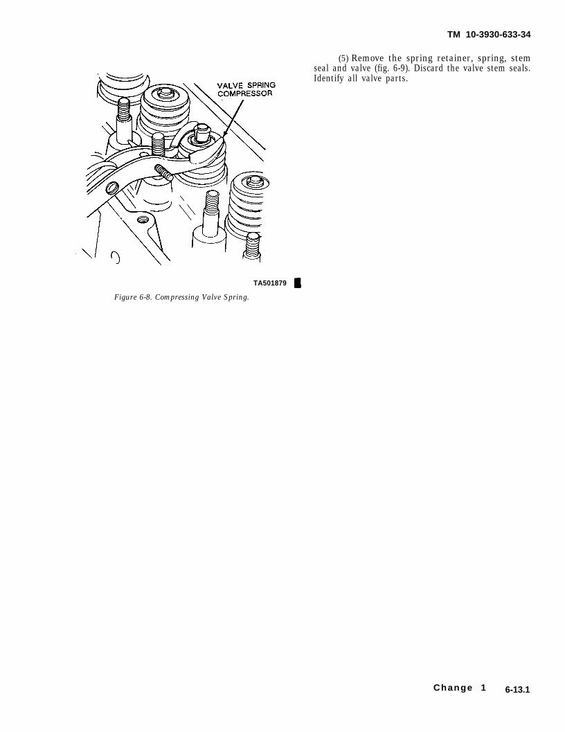
TM 10-3930-633-34
(5) Remove the spring retainer, spring, stemseal and valve (fig. 6-9). Discard the valve stem seals.Identify all valve parts.
TA501879
Figure 6-8. Compressing Valve Spring.
Change 1 6-13.1
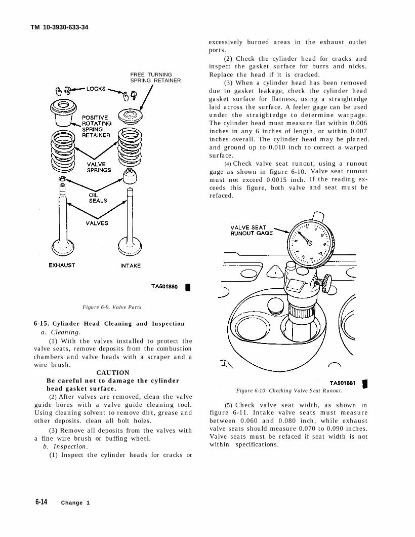
TM 10-3930-633-34
excessively burned areas in the exhaust outlet
FREE TURNINGSPRING RETAINER
Figure 6-9. Valve Parts.
6-15. Cylinder Head Cleaning and Inspectiona. Cleaning.
(1) With the valves installed to protect thevalve seats, remove deposits from the combustionchambers and valve heads with a scraper and awire brush.
CAUTIONBe careful not to damage the cylinderhead gasket surface.(2) After valves are removed, clean the valve
guide bores with a valve guide cleaning tool.Using cleaning solvent to remove dirt, grease andother deposits. clean all bolt holes.
(3) Remove all deposits from the valves witha fine wire brush or buffing wheel.
b. Inspection.(1) Inspect the cylinder heads for cracks or
ports.(2) Check the cylinder head for cracks and
inspect the gasket surface for burrs and nicks.Replace the head if it is cracked.
(3) When a cylinder head has been removeddue to gasket leakage, check the cylinder headgasket surface for flatness, using a straightedgelaid across the surface. A feeler gage can be usedunder the straightedge to determine warpage.The cylinder head must measure flat within 0.006inches in any 6 inches of length, or within 0.007inches overall. The cylinder head may be planed.and ground up to 0.010 inch to correct a warpedsurface.
(4) Check valve seat runout, using a runoutgage as shown in figure 6-10.must not exceed 0.0015 inch.ceeds this figure, both valverefaced.
Valve seat runoutIf the reading ex-and seat must be
Figure 6-10. Checking Valve Seat Runout.
(5) Check valve seat width, as shown infigure 6-11. Intake valve seats must measurebetween 0.060 and 0.080 inch, while exhaustvalve seats should measure 0.070 to 0.090 inches.Valve seats must be refaced if seat width is notwithin specifications.
6-14 Change 1

TM 10-3930-633-34
(6)
Figure 6-11. Checking Valve Seat Width
Check the breakaway torque of all rockerarm studs. 4.5 to 15 ft/lbs should be required(counterclockwise) to break the stud away. Ifbreakaway torque is less than this, replace thestud with an oversize stud.
6-16. Cylinder Head Repaira. Rocker Arm Stud Replacement. Rocker
arm studs that are broken or have damagedthreads may be replaced with standard studs.Loose studs may be replaced with 0.006, 0.010, or0.015 inch oversize studs, which are available forservice (TM 10-3930-633-34P). Oversize studsmay be identified by measuring the stud diameterat a point 1-1/8 inches from the pilot end of thestud. The stud diameters are:
0.006 oversize . . . . . . . . . . . . . . . . . . . . . ..0.3774-0.37810.010 oversize . . . . . . . . . . . . . . . . . . . . ...0.3814-0.38210.015 oversize . . . . . . . . . . . . . . . . . . . ...0.3864-0.3871
b. Replacement Procedure.(1) If the rocker arm stud was broken off
flush with the stud boss, use an easy-out toremove the broken stud following the instructionsof the tool manufacturer.
(2) When going from a standard size rockerarm stud to an 0.010 or 0.015 inch oversize stud,always use the 0.006 inch oversize reamer beforefinish reaming with the 0.010 or 0.015 inchoversize reamer.
(3) If a loose rocker arm stud is beingreplaced, ream the stud bore using the properreamer (or reamers in sequence) for the selectedoversize stud (fig. 6-12). Make sure the metalparticles do not enter the valve area.
Figure 6-12. Reaming Rocker Arm Stud Bore.
(4) Install new studs with a stud driver toolas shown in figure 6-13. Exercise care to set newstud at same height as adjacent studs not beingreplaced.
6-15

TM 10-3930-633-34
Figure 6-13. Installing New Rocker Arm Studs.
(5) Align the stud and installer with the studbore, then tap the sliding driver until it bottoms.When the installer contacts the stud boss, thestud is installed to its correct height.
b. Reaming Valve Guides. If it becomesnecessary to ream a valve guide (fig. 6-14) toinstall a valve with an oversize stem, a reamingkit is available which contains the followingreamer and pilot combinations: an 0.003 inch OSreamer with a standard diameter pilot, an 0.015inch OS reamer with an 0.003 inch OS pilot, andan 0.030 inch reamer with an 0.015 inch OS pilot.
TS007343
Figure 6-14. Reaming Valve Guides.
(1) When reaming guides for oversize valves,use the smallest reamer first, then the finish sizereamer.
(2) Use a suitable scraper or deburring toolto break the sharp edge at the top of the valveguide (fig. 6-14).
(3) Always reface seat after reaming valveguides.
c. Refacing Value Seats. Refacing of the valveseat should be closely coordinated with therefacing of the valve face so that the finished seatand valve face will be concentric and the specifiedinterference fit will be maintained. This is im-portant so that the valve and seat will have acompression tight fit. Be sure that the refacergrinding wheels are properly dressed.
(1) Grind the valve seats to a true 45 degreeangle (figure 6-15 ). Remove only enough stock toclean up pits and grooves or to correct the valveseat runout. After the seat has been refaced, use aseat width scale or a machinist scale to measurethe seat width. Narrow the seat, if necessary, tobring it within specifications.
6-16

TM 10-3930-633-34
Figure 6-15. Value Seat Refacing.
(2) If the valve seat width exceeds themaximum limit, remove enough stock from thetop edge and/or bottom edge of the seat to reducethe width to specifications.
(3) Use a 60 degree angle grinding wheel toremove stock from the bottom of the seats (raisethe seats) and use a 30 degree angle wheel toremove stock from the top of the seats (lower theseats).
(4) The finished valve seat should contactthe approximate center of the valve face. It isgood practice to determine where the valve seatcontacts the face. To do this, coat the seat withPrussian blue and set the valve in place. Rotatethe valve with light pressure. If the blue istransferred to the center of the valve face, thecontact is satisfactory. If the blue is transferredto the top edge of the valve face, lower the valveseat. If the blue is transferred to the bottom edgeof the valve face, raise the valve seat.
6-17. Valve Cleaning and Inspectiona. Cleaning. Remove carbon deposits and
sludge or varnish formation from valve stems,seat, and faces with a fine wire brush or buffingwheel.
b. Inspection. Refer to figure 6-16 for allinspection and measurement points, and proceedas follows:
Figure 6-16. Valve Inspection.
(1) Inspect the valve face and the edge of thehead for pits, grooves, or scoring.
(2) Check the stem for straightness and forcracks or grooves and scoring around the lockarea.
(3) Check the head of the valve for burningor erosion, cupping, warpage or cracks. Whileminor pits or grooves may be removed duringrefacing, badly damaged valves should bereplaced.
(4) Check the valve face runout. It shouldnot exceed the specified wear limit. If the runoutexceeds 0.002 inches, the valve should be replacedor refaced.
(5) Check the valve stem to valve guideclearance of each valve in its respective valveguide with a dial indicator as shown in figure 6-17. Use a flat end indicator point. Clearanceshould not exceed 0.0010 to 0.0027 for newvalves. Maximum wear limit for valves in serviceis 0.0055.
6-17

TM 10-3930-633-34
Figure 6-17. Checking Valve Stem Clearance.
(6) Install the tool on the valve stem until itis fully seated, and tighten the knurled setscrewfirmly. Permit the valve to drop away from itsseat until the tool contacts the upper surface ofthe valve guide.
(7) Position the dial indicator with its flat tipagainst the center portion of the tool’s sphericalsection at approximately 90 degrees to the valvestem axis. Move the tool back and forth in linewith the indicator stem. Take a reading on thedail indicator without removing the tool from thevalve guide upper surface. Divide the reading bytwo, the division factor for the tool.
6-18. Refacing Valvesa. Machining. The valve refacing operation
should be closely coordinated with the valve seatrefacing operations to that the finished angles ofthe valve face and of the valve seat will be tospecifications and provide a compression tight fit.Be sure that the refacer grinding wheels areproperly dressed.
(1) If the valve face runout is excessiveand/or to remove pits and grooves, reface thevalves to a true 44 degree angle. Remove onlyenough stock to correct the runout or to clean up
the pits and grooves. If the edge of the valve headis less than 1 /32 inch thick after grinding (fig. 6-16), replace the valve as the valve will run too hotin the engine.
(2) The interference fit of the valve and seatshould not be lapped out.
(3) Remove all grooves or score marks fromthe end of the valve stem, and chamfer it asnecessary. Do not remove more than 0.010 inchfrom the end of the valve stem.
(4) If the valve and/or valve seat has beenrefaced, it will be necessary to check the clearancebetween the rocker arm pad and the valve stemwith the valve train assembly installed in theengine.
b. Select Fitting Valves. If the valve stem tovalve guide clearance exceeds the wear limit,ream the valve guide for the next oversize valvestem. Valves with oversize stem diameters of0.003, 0.015 and 0.030 inch are available forservice. Always reface the valve seat after thevalve guide has been reamed.
6-19. Valve Springs Inspectiona. Checking Spring Pressure. Check the valve
spring for proper pressure as shown in figure 6-18at the specified spring lengths. Weak valvesprings cause poor performance; therefore, if thepressure of any spring is lower than the wearlimit, replace the spring, See table 6-4 fordimensions and readings.
Figure 6-18. Checking Valve Spring Pressure.
6-18
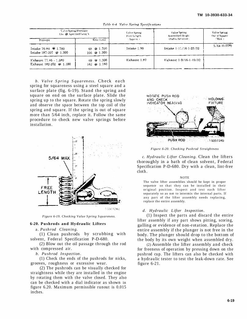
Table 6-4.
TM 10-3930-633-34
b. Valve Spring Squareness. Check eachspring for squareness using a steel square and asurface plate (fig. 6-19). Stand the spring andsquare on end on the surface plate. Slide thespring up to the square. Rotate the spring slowlyand observe the space between the top coil of thespring and square. If the spring is out of squaremore than 5/64 inch, replace it. Follow the sameprocedure to check new valve springs beforeinstallation.
Figure 6-19. Checking Value Spring Squareness.
6-20. Pushrods and Hydraulic Liftersa. Pushrod Cleaning.
(1) Clean pushrods by scrubbing withsolvent, Federal Specification P-D-680.
(2) Blow out the oil passage through the rodwith compressed air.
b. Pushrod Inspection.(1) Check the ends of the pushrods for nicks,
grooves, roughness or excessive wear.(2) The pushrods can be visually checked for
straightness while they are installed in the engineby rotating them with the valve closed. They alsocan be checked with a dial indicator as shown infigure 6.20. Maximum permissible runout is 0.015inches.
Figure 6-20. Checking Pushrod Straightness
c. Hydraulic Lifter Cleaning. Clean the liftersthoroughly in a bath of clean solvent, FederalSpecification P-D-680. Dry with a clean, lint-freecloth.
NOTEThe valve lifter assemblies should be kept in propersequence so that they can be installed in theiroriginal position. Inspect and test each lifterseparately so as not to intermix the internal parts. Ifany part of the lifter assembly needs replacing,replace the entire assembly.
d. Hydraulic Lifter Inspection.(1) Inspect the parts and discard the entire
lifter assembly if any part shows pitting, scoring,galling or evidence of non-rotation. Replace theentire assembly if the plunger is not free in thebody. The plunger should drop to the bottom ofthe body by its own weight when assembled dry.
(2) Assemble the lifter assembly and checkfor freeness of operation by pressing down on thepushrod cup. The lifters can also be checked witha hydraulic tester to test the leak-down rate. See figure 6-21.
6-19
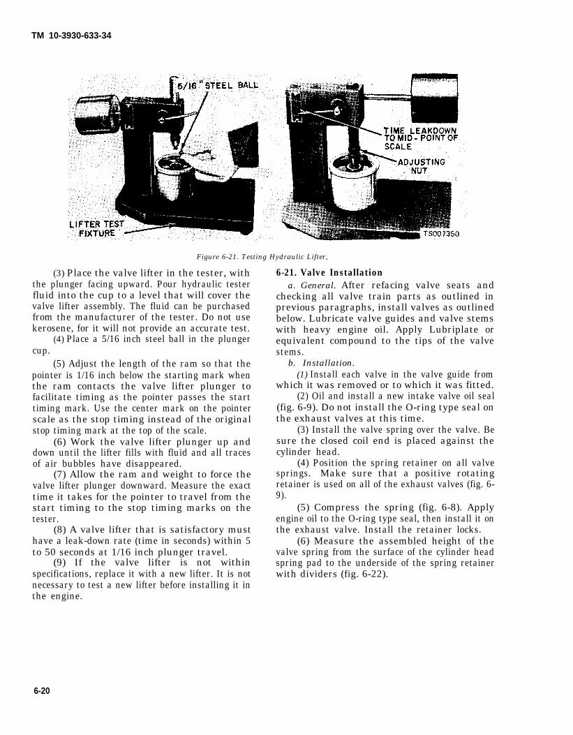
TM 10-3930-633-34
Figure 6-21. Testing Hydraulic Lifter,
(3) Place the valve lifter in the tester, withthe plunger facing upward. Pour hydraulic testerfluid into the cup to a level that will cover thevalve lifter assembly. The fluid can be purchasedfrom the manufacturer of the tester. Do not usekerosene, for it will not provide an accurate test.
(4) Place a 5/16 inch steel ball in the plungercup.
(5) Adjust the length of the ram so that thepointer is 1/16 inch below the starting mark whenthe ram contacts the valve lifter plunger tofacilitate timing as the pointer passes the starttiming mark. Use the center mark on the pointerscale as the stop timing instead of the originalstop timing mark at the top of the scale.
(6) Work the valve lifter plunger up anddown until the lifter fills with fluid and all tracesof air bubbles have disappeared.
(7) Allow the ram and weight to force thevalve lifter plunger downward. Measure the exacttime it takes for the pointer to travel from thestart timing to the stop timing marks on thetester.
(8) A valve lifter that is satisfactory musthave a leak-down rate (time in seconds) within 5to 50 seconds at 1/16 inch plunger travel.
(9) If the valve lifter is not withinspecifications, replace it with a new lifter. It is notnecessary to test a new lifter before installing it inthe engine.
6-21. Valve Installationa. General. After refacing valve seats and
checking all valve train parts as outlined inprevious paragraphs, install valves as outlinedbelow. Lubricate valve guides and valve stemswith heavy engine oil. Apply Lubriplate orequivalent compound to the tips of the valvestems.
b. Installation.(1) Install each valve in the valve guide from
which it was removed or to which it was fitted.(2) Oil and install a new intake valve oil seal
(fig. 6-9). Do not install the O-ring type seal onthe exhaust valves at this time.
(3) Install the valve spring over the valve. Besure the closed coil end is placed against thecylinder head.
(4) Position the spring retainer on all valvesprings. Make sure that a positive rotatingretainer is used on all of the exhaust valves (fig. 6-9).
(5) Compress the spring (fig. 6-8). Applyengine oil to the O-ring type seal, then install it onthe exhaust valve. Install the retainer locks.
(6) Measure the assembled height of thevalve spring from the surface of the cylinder headspring pad to the underside of the spring retainerwith dividers (fig. 6-22).
6-20

TM 10-3930-633-34
(7) Check the dividers against a scale. If theassembled height is greater than the specifiedlimit (table 6-4), install the necessary 0.030 inchthick spacer(s) between the cylinder head springpad and the valve spring to bring the assembledheight to the recommended dimension. Do notinstall spacers unless necessary. Use of spacers inexcess of recommendations will result in over-stressing the valve springs and overloading thecamshaft lobes which could lead to springbreakage and worn camshaft lobes.
Figure 6-22. Checking Valve Spring Height.
Section V. CYLINDER BLOCK
6-22. Cylinder Block Cleaninga. After any cylinder bore repair operation,
such as honing or deglazing, clean the bore(s)with soap or detergent and water. Then,thoroughly rinse the bore(s) with clean water toremove the soap or detergent, and wipe thebore(s) dry with a clean, lint-free cloth. Finally,wipe the bore(s) with a clean cloth dipped inengine oil. If these procedures are not followed,rusting of the cylinder bore(s) may occur.
b. If the engine is disassembled, thoroughlyclean the block in solvent. Remove old gasketmaterial from all machined surfaces. Remove allpipe plugs that seal oil passages; then clean outall the passages, Blow out all passages, boltholes, etc., with compressed air.
c. Make sure the threads in the cylinder headbolt holes are clean. Dirt in the threads may causebinding and result in a false torque reading. Use atap to true-up threads and to remove anydeposits.
6-23. Cylinder Block Inspectiona. After the block has been thoroughly cleaned,
check it for cracks. Minute cracks not visible tothe naked eye may be detected by coating thesuspected area with a mixture of 25 percentkerosene and 75 percent light engine oil. Wipe the
part dry and immediately apply a coating of zincoxide dissolved in wood alcohol. If cracks arepresent, the coating will become discolored at thecracked area. Replace the block if it is cracked.
b. Check all machined gasket surfaces forburrs, nicks, scratches and scores. Remove minorimperfections with an oil stone. Check thecylinder block for flatness of the cylinder headgasket surface following the procedure andspecifications recommended for the cylinder head.The cylinder block can be machined to bring thecylinder head gasket surface within the flatnessspecifications, but not to exceed 0.010 inch stockremoval from the original gasket surface.
c. Replace all expansion-type plugs that showevidence of leakage. See paragraph 6-25.
d. Inspect the cylinder walls for scoring,roughness, or other signs of wear. Check thecylinder bore for out-of-round and taper. Measurethe bore with an accurate bore gage following theinstructions of the manufacturer. Measure thediameter of each cylinder bore at the top, middleand bottom with the gage placed at right anglesand parallel to the centerline of the engine (fig. 6-23). Use only the measurements obtained at 90degrees to the engine centerline when calculatingthe piston to cylinder bore clearance.
6-21

TM 10-3930-633-34
Figure 6-23. Checking Cylinder Bores.
e. Refinish cylinders that are deeply scoredand/or when out-of-round and/or taper exceedsthe wear limits:
Maximum out-of-round . . . . . . . . . . . . . . . . . . . ...0.001Wear limit . . . . . . . . . . . . . . . . . . . . . . . . . . . . . ...0.005Maximum taper . . . . . . . . . . . . . . . . . . . . .,.....0.001Wear limit . . . . . . . . . . . . . . . . . . . . . . . . . ...0.010Cylinder bore surface finish RMS . . . . . . . . . . ...15-35
f. If the cylinder walls have minor surfacedamage, but the out-of-round and taper arewithin limits, it may be possible to remove suchdamage by honing the cylinder walls and in-stalling new service piston rings providing thepiston clearance is within specified limits.
6-24. Refinishing Cylinder Wallsa. Machining. Cylinder walls that are severely
marred and/or worn beyond the specified limitsshould be refinished. Before any cylinder isrefinished, all main bearing caps must be in placeand tightened to the proper torque so that thecrankshaft bearing bores will not becomedistorted from the refinishing operation.
(1) Refinish only the cylinder or cylindersthat require it. All pistons are the same weight,both standard and oversize; therefore, varioussizes of pistonsengine balance.
(2) Refinish
6-22
can be used without upsetting
the cylinder with the most wear
first to determine the maximum oversize. If thecylinder will not clean up when refinished for themaximum oversize piston recommended, replacethe block,
(3) Refinish the cylinder to within ap-proximately 0.0015 inch of the required oversizeddiameter. This will allow enough stock for thefinal step of honing so that the correct surfacefinish and pattern are obtained.
(4) For the proper use of the refinishingequipment, follow the instructions of themanufacturer. Only experienced personnel shouldbe allowed to perform this work.
b. Honing. H o n i n g is recommended forrefinishing cylinder walls only when the wallshave minor scuffs or scratches, or for fittingpistons to the specified clearance. The grade ofhone to be used is determined by the amount ofmetal to be removed. Follow the instructions ofthe hone manufacturer. If coarse stones are usedto start the honing operation, leave enoughmaterial so that all hone marks can be removedwith the finishing hone which is used to obtain theproper piston clearance.
(1) Use a motor-driven, spring pressure-typehone at a speed of 300-500 RPM. Hones of gritsizes 180-220 will normally provide the desiredbore surface finish. When honing the cylinderbores, use a lubricant mixture of equal parts ofkerosene and SAE No. 20 MOTOR OIL.
(2) Operate the hone in such a way as toproduce a cross-hatch finish on the cylinder bore.The cross-hatch pattern should be at an angle ofapproximately 30 degrees to the cylinder bore.
(3) After the final operation in either of thetwo refinishing methods described and prior tochecking the piston fit, thoroughly clean and oilthe cylinder walls. Mark the pistons tocorrespond to the cylinders in which they are to beinstalled.
6-25. Replacing Core Plugsa. Removal.
(1) To remove larger core plugs, drill a ½ -inch diameter hole in the center of the plug andremove with a pilot bearing puller or large driftpunch.
(2) On smaller plugs, drill a ¼ -inch diameterhole in the center of the plug and pry out with asmall pin punch.
(3) Clean and inspect plug bore. Checkcarefully for any damage that would interferewith the proper sealing of the plug. If the bore isdamaged it will be necessary to true the surfaceby boring for the next specified oversize plug. SeeTM 10-3930-633-34P.
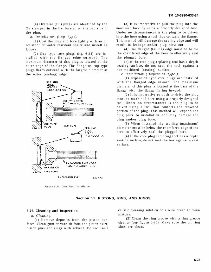
(4) Oversize (OS) plugs are identified by theOS stamped in the flat located on the cup side ofthe plug.
b. Installation (Cup Type).(1) Coat the plug and bore lightly with an oil
resistant or water resistant sealer and install asfollows :
(2) Cup type core plugs (fig. 6-24) are in-stalled with the flanged edge outward. Themaximum diameter of this plug is located at theouter edge of the flange. The flange on cup typeplugs flares outward with the largest diameter atthe outer (sealing) edge.
TM 10-3930-633-34
(3) It is imperative to pull the plug into themachined bore by using a properly designed tool.Under no circumstances is the plug to be driveninto the bore using a tool that contacts the flange.This method will damage the sealing edge and willresult in leakage and/or plug blow out.
(4) The flanged (tailing) edge must be belowthe chamfered edge of the bore to effectively sealthe plugged bore.
(5) If the core plug replacing tool has a depthseating surface, do not seat the tool against anon-machined (casting) surface.
c. Installation ( Expansion Type ).(1) Expansion type core plugs are installed
with the flanged edge inward. The maximumdiameter of this plug is located at the base of theflange with the flange flaring inward.
(2) It is imperative to push or drive the pluginto the machined bore using a properly designedtool, Under no circumstances is the plug to bedriven using a tool that contacts the crownedportion of the plug. This method will expand theplug prior to installation and may damage theplug and/or plug bore.
(3) When installed the trailing (maximum)diameter must be below the chamfered edge of thebore to effectively seal the plugged bore.
(4) If the core plug replacing tool has a depthseating surface, do not seat the tool against a castsurface.
Figure 6-24. Core Plug Installation
Section VI. PISTONS, PINS, AND RINGS
6-26. Cleaning and Inspection caustic cleaning solution or a wire brush to clean
a. Cleaning. pistons.
(1) Remove deposits from the piston sur- (2) Clean the ring groove with a ring groove
faces. Clean gum or varnish from the piston skirt, cleaner (see figure
piston pins and rings with solvent. Do not use a slots are clean.6-25). Make sure the oil ring
6-23

TM 10-3930-633-34
Figure 6-25. Cleaning Ring Grooves.
b. Inspection.(1) Carefully inspect the pistons for fractures
at the ring lands, skirts, and pin bosses, and forscuffed, rough, or cored skirts. If the lower innerportion of the ring grooves have high steps,replace the piston. The step will interfere withring operation and cause excessive ring sideclearance.
(2) Spongy, eroded areas near the edge of thepiston top are usually caused by detonation orpre-ignition. A shiny surface on the thrust surfaceof the piston, offset from the centerline between
the piston pin holes, can be caused by a bentconnecting rod. Replace pistons that show signsof excessive wear, wavy ring lands or fractures, ordamage from detonation or pre-ignition.
(3) Check the piston cylinder bore clearanceby measuring the piston and bore diameters.Refer to table 6-5 for the proper clearance. Referto paragraph 6-23 for the bore measurementprocedure. Measure the OD of the piston withmicrometers at the centerline of the piston boreand at 90 degrees to the pin bore axis. Check the
ring side clearance following the procedure underFitting Piston Rings in this section.
(4) Replace piston pins showing signs offracture, etching or wear. Check the piston pin fitin the piston and rod. Refer to table 6-5.
(5) Check the OD of the piston pin and the IDof the pin bore in the piston. Replace any pistonpin or piston that is not within specifications(table 6-5).
(6) Replace all rings that are scored, chippedor cracked. Check the end gap and side clearance.It is good practice to always install new ringswhen overhauling an engine. Rings should not betransferred from one piston to another regardlessof mileage.
Table 6-5. Piston, Pin, and Ring Fits
ITEM INCHES
P I S T O N
Diameter (red code).... . . . . . . . . . . . . . . . . . .. . . . . . . . . . . . . . . . . . . . . . . . . . . . . ...3.9984-3.9990
Diameter (blue code) . . . . . . . . . . . . . . .. .. . . . . . . . .. . . . . .. .3.9996-4.0002
Diameter (0.003 oversize). . . . . . . . . . . . . . . . . . . . . . . . . . ... . . . . . . . . . . . ...4.0008-4.0014
Piston-to-bore clearance. . . . . . .. . . . . . . . .. . . . . . . . . . . .. . . .0.0014-0.0022
Pin bore diameter. . . . . . . . . . .. . . . . . . . . . . . . . . . . . . . . . . . .. . .0.9753 -0.9756
R i n g g r o o v e w i d t h :
Top. . . . . . . . . . . . . .. . . . . . . . . . . . . . . . . . . . . . . . . .0.0800 -0.0810
Bottom. . . . . . . . . . . . . . . . . . . . .. . . . . .. . 0 . 0 8 0 0 - 0 . 0 8 1 0
Oil ring. . . . . . . . . . . . . . . . . . . . . . . . . . . . . . . . . . . ..0.1880-0.1890
P I S T O N P I N
Length . . . . . . . . . . . . . . . .. .. . . .. . . . . . . . . . . . .. . . .. . . . . . 3 . 1 5 0 - 3 . 1 7 0
D i a m e t e r ( s t d ) . . . . . . . . . . . . . . . . . . . . . . . . . . . . . . 0 . 9 7 5 0 - 0 . 9 7 5 3
D i a m e t e r ( . 0 0 1 ) . . . . . . . . . . . . . . . . . . . . . . . . . . . . . . . . . 0 . 9 7 6 0 - 0 . 9 7 6 3
D i a m e t e r ( . 0 0 2 ) . . . . . . . . . . . . . . . . . . . . . . . . . . . . . 0 , 9 7 7 0 - 0 . 9 7 7 3
C l e a r a n c e ( i n p i s t o n ) . . . . . . . .. . . .. . . . . . . . . . . . . . . . . . . . . . . . . 0 . 0 0 0 2 - 0 . 0 0 0 4
C l e a r a n c e ( i n r o d b u s h i n g ) . . . . . . . . . . . . . . . . . . . . . . . . . . . . .. . . . . . . . .inter ference
P I S T O N R I N G S
W i d t h ( c o m p r e s s i o n r i n g s ) . . . . . . . . .. . . . .. . . . . . . . .. . . . . . . .. . . . 0 . 0 7 7 0 - 0 . 0 7 8 0
Side c l earance ( topp ing ) . . . . . . .. . . .. . . . . . . . . . . . . . . . . . . . . . . .. . . . . . . . 0 . 0 0 2 - 0 . 0 0 4
S i d e c l e a r a n c e ( b o t t o m r i n g ) . . . . . . . . .. . . .. . . . . . . . . ... . . . . . . . . . . .. 0 . 0 0 2 5 - 0 . 0 0 4 0
S i d e c l e a r a n c e ( o i l r i n g ) . . . . . . . . . . . . ... . . . . .. . . . . . . . . . . . . . . . . .. . . snug f i t
R i n g g a p ( t o p r i n g ) . . . . . . . . . . . . . . . . . . . . . . . . . . . .. . . . . . . 0 . 0 1 0 - 0 . 0 2 0
R i n g g a p ( b o t t o m r i n g ) . . . . . . . . . . . . . . . . . . . . . . .. .. . . . . . , . 0 . 0 1 0 - 0 . 0 2 0
R i n g g a p ( o i l r i n g ) . . . . . . . . . . . . . . . . . . . . . . . . . . . . . . . 0 . 0 1 5 - 0 . 0 5 5
6-24

TM 10-3930-633-34
6-27. Fitting Pistons and Rings to BorePistons are available for service replacement in
the standard size as well as in 0.020, 0.030 and0.040 inch oversizes. All pistons are matched forweight, regardless of size. Standard. pistons arecoded red or blue, or have “0.003 OS” stamped onthe dome. Refer to table 6-5 for dimensions.
a. Fitting Pistons.(1) Measure the cylinder bore and select the
piston to assure the proper clearance. When thebore diameter is in the lower one-third of thespecified range, a red piston should be used.When the bore diameter is in the middle one-thirda blue piston should be used. When the borediameter is in the upper one-third, the 0.003 OSpiston should be used.
(2) Measure the piston diameter to ensurethat the specified clearance is obtained. It may benecessary periodically to use another piston(within the same grade size) that is either slightlylarger, or smaller, to achieve the specifiedclearance.
(3) If none can be fitted, refinish the cylinderto provide the proper clearance for the piston.
(4) When a piston has been fitted, mark it forassembly in the cylinder to which it was fitted.
b. Fitting Rings. If the taper, out-of-round andpiston to cylinder bore clearance conditions of thecylinder bore are within specified limits, newpiston rings will give satisfactory service. If newrings are to be installed in a used cylinder that hasnot been refinished, remove the cylinder wallglaze (para 6-24, Refinishing Cylinder Walls). Besure to clean the cylinder bore thoroughly.
(1) Calculate the size piston to be used bytaking a cylinder bore check, or use the properlyfitted piston, determined in subparagraph a.
(2) Select the proper ring set for the sizecylinder bore.
(3) Position the ring in the cylinder bore inwhich it is going to be used.
(4) Push the ring down into the bore areawhere normal ring wear is not encountered.
(5) Use the head of a piston to position thering in the bore so that the ring is square with thecylinder wall. Use caution to avoid damage to thering or cylinder bore.
(6) Measure the gap between the ends of thering with a feeler gage (fig. 6-26). If the ring gapis less or greater than the specified limits, tryanother ring set.
Figure 6-26. Checking Ring Gap.
(7) Check the ring side clearance of thecompression rings with a feeler gage insertedbetween the ring and its lower land (fig. 6-27).The gage should slide freely around the entire ringcircumference without binding. Any wear thatoccurs will form a step at the inner portion of thelower land. If the lower lands have high steps, thepiston should be replaced.
Figure 6-27. Checking Ring Side Clearance.
6-28. Assembly and Installationa. General. The piston, connecting rod and
related parts are shown in figure 6-28. Check thefit of a new piston in the cylinder bore beforeassembling the piston and piston pin to theconnecting rod, following the procedures insubparagraph b. The piston pin bore of a con-necting rod and the diameter of the piston pinmust be within specifications.
6-25
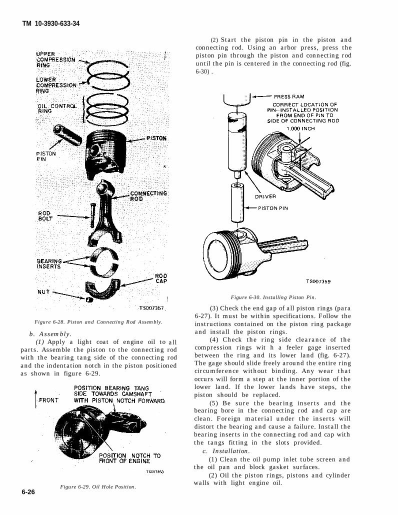
TM 10-3930-633-34
Figure 6-28. Piston and Connecting Rod Assembly.
b. Assembly.(1) Apply a light coat of engine oil to all
parts. Assemble the piston to the connecting rodwith the bearing tang side of the connecting rodand the indentation notch in the piston positionedas shown in figure 6-29.
Figure 6-29. Oil Hole Position.
(2) Start the piston pin in the piston andconnecting rod. Using an arbor press, press thepiston pin through the piston and connecting roduntil the pin is centered in the connecting rod (fig.6-30) .
Figure 6-30. Installing Piston Pin.
(3) Check the end gap of all piston rings (para6-27). It must be within specifications. Follow theinstructions contained on the piston ring packageand install the piston rings.
(4) Check the ring side clearance of thecompression rings wit h a feeler gage insertedbetween the ring and its lower land (fig. 6-27).The gage should slide freely around the entire ringcircumference without binding. Any wear thatoccurs will form a step at the inner portion of thelower land. If the lower lands have steps, thepiston should be replaced.
(5) Be sure the bearing inserts and thebearing bore in the connecting rod and cap areclean. Foreign material under the inserts willdistort the bearing and cause a failure. Install thebearing inserts in the connecting rod and cap withthe tangs fitting in the slots provided.
c. Installation.(1) Clean the oil pump inlet tube screen and
the oil pan and block gasket surfaces.(2) Oil the piston rings, pistons and cylinder
walls with light engine oil.6-26

TM 10-3930-633-34
(3) Be sure to install the pistons in the samecylinders from which they were removed or towhich they were fitted. The connecting rods andbearing caps are numbered from 1 to 6 beginningat the front of the engine. The number on theconnecting rod and bearing cap must be on the
same side of rod when installing in the cylinderbore. If a connecting rod is ever transferred fromone cylinder block to another or from one cylinderto another, new bearings should be fitted and theconnecting rod should be renumbered tocorrespond with the new cylinder number.
(4) Make sure the ring gaps are properlyspaced around the circumference of the piston(figure 6-31). Oil the rings, then install a pistonring compressor on the piston. Make sure that theindentation in the head of piston is toward thefront, then push the piston into its bore with thehandle end of a hammer until it is slightly belowthe top of the cylinder (fig. 6-32). Be sure to guidethe connecting rods to avoid damaging thecrankshaft journals.
Figure 6-32. Piston Installation.
(5) Check the clearance of each bearingfollowing the procedure under paragraph 6-33,Connecting Rod Bearing Replacement.
(6) After the bearings have been fitted, applya light coat of engine oil to the journals andbearings.
(7) Turn the crankshaft throw to the bottomof its stroke, then push the piston all the waydown until the connecting rod bearing seats onthe crankshaft journal. Install the connecting rodcap. Torque the nuts to specifications.
(8) After the piston and connecting rodassemblies have been installed, check the con-necting rod side clearance on each crankshaftjournal (fig. 6-33 ). Side clearance should be0.0060 to 0.0130 inches.
Figure 6-31. Piston Ring Gap Spacing.
Figure 6-33. Checking Rod Side Clearance.
Change 1 6-27

TM 10-3930-633-34
(9) Prime the oil pump by filling the inletopening with oil and rotate the pump shaft until oilemerges from the outlet opening. Install the oil pumpand the oil pump inlet tube. Install the oil pan andreplated parts.
(10) Clean the cylinder head and cylinder block gasket surface. Clean the exhaust manifold andexhaust pipe gasket surfaces.
(11) If the cylinder head was removed for a cyl-inder head gasket replacement, check the flatness ofthe head and block gasket surfaces. Cylinder headmust be flat within 0.006 inch in any 6 inches of sur-face, and within 0.007 inch overall.
(12) Position the gasket over the dowel pins onthe cylinder block.
(13) Install lifting eyes on the cylinder head inthe location shown in figure 6-7.3 and use a floorcrane and lifting sling to lift the cylinder head overthe cylinder block. Lower it carefully until it is prop-erly positioned on the block and dowel pins. Removethe hoist and lifting eyes.
(14) Coat the threads of the cylinder head boltswith engine oil. Install the bolts.
(15) Torque the bolts in sequence (fig. 6-7.3)to specification in the following steps:
(a) Step 1. Torque in sequence to 50-55ft/lbs.
(b) Step 2. Torque in sequence to 60-65ft/lbs.
(c) Step 3. Torque in sequence to 70-75ft/lbs.When cylinder head bolts have been tightened it isnot necessary to retorque the bolts after extendedoperation.
(16) Apply Lubriplate or equivalent to bothends of the push rods. Install the push rods in their
original bore, positioning the lower end of the rods inthe valve lifter socket.
(17) Apply Lubriplate or equivalent to therocker arm fulcrum seat and the fulcrum seat socketin the rocker arm. Position the rocker arms andtighten the stud nuts just enough to hold the pushrods in position. Adjust the valve clearance accordingto paragraph 6-13.1.
(18) Clean the valve rocker arm cover. Placethe new gasket in the cover making sure that the tabsof the gasket engage the notches provided in thecover. Position the cover, making sure that the gasketseats evenly around the cylinder head. Install thecover bolts and torque in sequence (starting in thecenter) to specifications.
(19) Connect the spark plug wires to the sparkplugs.
(20) Connect the crankcase vent hose to the in-let tube in the intake manifold. Install the crankcaseventilation regulator valve in the valve rocker armcover.
(21) Position the fuel inlet line and the distribu-tor vacuum line on the engine. Connect thedistributor vacuum line to the distributor and carbu-retor. Connect the carburetor fuel inlet line to thecarburetor and fuel pump.
(22) Connect the accelerator cable to the car-buretor. Install the accelerator cable retractingspring. Connect the choke cable to the carburetor.
(23) Connect the radiator upper hose to thecoolant outlet housing, but do not tighten the clamp.
(24) Fill and bleed the cooling system, thentighten the heater hose clamp.
(25) Operate the engine until engine tempera-tures have stabilized. Adjust the engine idle speedand idle fuel mixture. Check for fuel, oil and coolantleaks.
(26) Install the air cleaner ductwork.
Section VII. CONNECTING RODS AND CRANKSHAFT
6-29. Crankshaft Removal and InstallationSee figure 6-34 for parts identification of
crankshaft and related parts.
6-28 Change 1

TM 10-3930-633-34
Figure 6-34. Crankshaft and Related Parts.
a. Removal.(1) Install the engine on a work stand. Re-
move the spark plugs to allow easy rotation of thecrankshaft.
(2) Remove the oil level dipstick.(3) Remove the crankshaft damper attaching
bolt and lockwasher. Remove the crankshaft damper(fig. 6-35).
Figure 6-35. Removing Crankshaft Damper.
C h a n g e 1 6-28.1/(6-28.2 Blank)

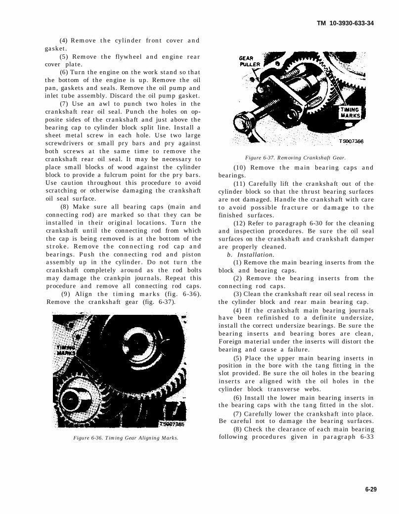
(4) Remove the cylinder front cover andgasket.
(5) Remove the flywheel and engine rearcover plate.
(6) Turn the engine on the work stand so thatthe bottom of the engine is up. Remove the oilpan, gaskets and seals. Remove the oil pump andinlet tube assembly. Discard the oil pump gasket.
(7) Use an awl to punch two holes in thecrankshaft rear oil seal. Punch the holes on op-posite sides of the crankshaft and just above thebearing cap to cylinder block split line. Install asheet metal screw in each hole. Use two largescrewdrivers or small pry bars and pry againstboth screws at the same time to remove thecrankshaft rear oil seal. It may be necessary toplace small blocks of wood against the cylinderblock to provide a fulcrum point for the pry bars.Use caution throughout this procedure to avoidscratching or otherwise damaging the crankshaftoil seal surface.
(8) Make sure all bearing caps (main andconnecting rod) are marked so that they can beinstalled in their original locations. Turn thecrankshaft until the connecting rod from whichthe cap is being removed is at the bottom of thestroke. Remove the connecting rod cap andbearings. Push the connecting rod and pistonassembly up in the cylinder. Do not turn thecrankshaft completely around as the rod boltsmay damage the crankpin journals. Repeat thisprocedure and remove all connecting rod caps.
(9) Align the timing marks (fig. 6-36).Remove the crankshaft gear (fig. 6-37).
Figure 6-36. Timing Gear Aligning Marks.
TM 10-3930-633-34
Figure 6-37. Removing Crankshaft Gear.
(10) Remove the main bearing caps andbearings.
(11) Carefully lift the crankshaft out of thecylinder block so that the thrust bearing surfacesare not damaged. Handle the crankshaft with careto avoid possible fracture or damage to thefinished surfaces.
(12) Refer to paragraph 6-30 for the cleaningand inspection procedures. Be sure the oil sealsurfaces on the crankshaft and crankshaft damperare properly cleaned.
b. Installation.(1) Remove the main bearing inserts from the
block and bearing caps.(2) Remove the bearing inserts from the
connecting rod caps.(3) Clean the crankshaft rear oil seal recess in
the cylinder block and rear main bearing cap.(4) If the crankshaft main bearing journals
have been refinished to a definite undersize,install the correct undersize bearings. Be sure thebearing inserts and bearing bores are clean,Foreign material under the inserts will distort thebearing and cause a failure.
(5) Place the upper main bearing inserts inposition in the bore with the tang fitting in theslot provided. Be sure the oil holes in the bearinginserts are aligned with the oil holes in thecylinder block transverse webs.
(6) Install the lower main bearing inserts inthe bearing caps with the tang fitted in the slot.
(7) Carefully lower the crankshaft into place.Be careful not to damage the bearing surfaces.
(8) Check the clearance of each main bearingfollowing procedures given in paragraph 6-33
6-29
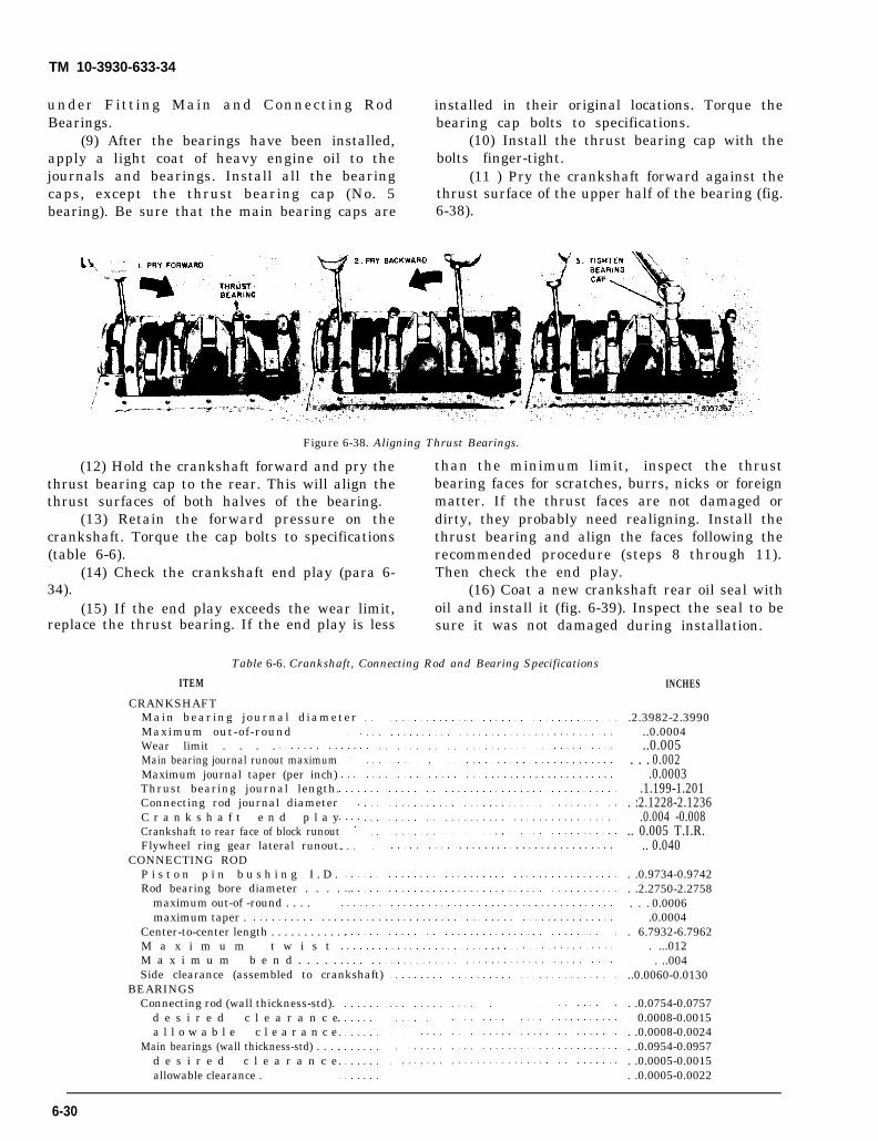
TM 10-3930-633-34
under Fitting Main and Connecting Rod installed in their original locations. Torque theBearings. bearing cap bolts to specifications.
(9) After the bearings have been installed, (10) Install the thrust bearing cap with theapply a light coat of heavy engine oil to the bolts finger-tight.journals and bearings. Install all the bearing (11 ) Pry the crankshaft forward against thecaps, except the thrust bearing cap (No. 5 thrust surface of the upper half of the bearing (fig.bearing). Be sure that the main bearing caps are 6-38).
Figure 6-38. Aligning Thrust Bearings.
(12) Hold the crankshaft forward and pry the than the minimum limit, inspect the thrustthrust bearing cap to the rear. This will align the bearing faces for scratches, burrs, nicks or foreignthrust surfaces of both halves of the bearing. matter. If the thrust faces are not damaged or
(13) Retain the forward pressure on the dirty, they probably need realigning. Install thecrankshaft. Torque the cap bolts to specifications thrust bearing and align the faces following the(table 6-6). recommended procedure (steps 8 through 11).
(14) Check the crankshaft end play (para 6- Then check the end play.34). (16) Coat a new crankshaft rear oil seal with
(15) If the end play exceeds the wear limit, oil and install it (fig. 6-39). Inspect the seal to bereplace the thrust bearing. If the end play is less sure it was not damaged
Table 6-6. Crankshaft, Connecting Rod and Bearing Specifications
ITEM
CRANKSHAFTMain bearing journal diameterMaximum out-of-roundWear limit . . . .Main bearing journal runout maximumMaximum journal taper (per inch)Thrust bearing journal length.Connecting rod journal diameterC r a n k s h a f t e n d p l a yCrankshaft to rear face of block runoutFlywheel ring gear lateral runout.
CONNECTING RODP i s t o n p i n b u s h i n g I . D .Rod bearing bore diameter . . . . .
maximum out-of -round . . . .maximum taper .
Center-to-center length . . . . . . . . . . . .M a x i m u m t w i s tM a x i m u m b e n d . . . . .Side clearance (assembled to crankshaft)
BEARINGSConnecting rod (wall thickness-std).
d e s i r e d c l e a r a n c ea l l o w a b l e c l e a r a n c e
Main bearings (wall thickness-std) . . . .d e s i r e d c l e a r a n c eallowable clearance .
during installation.
INCHES
.2.3982-2.3990..0.0004..0.005
. . . 0.002.0.0003
.1.199-1.201. :2.1228-2.1236
.0.004 -0.008.. 0.005 T.I.R.
.. 0.040
. .0.9734-0.9742
. .2.2750-2.2758. . . 0.0006
.0.0004. 6.7932-6.7962
. ...012. ..004
..0.0060-0.0130
. .0.0754-0.07570.0008-0.0015
. .0.0008-0.0024
. .0.0954-0.0957
. .0.0005-0.0015
. .0.0005-0.0022
6-30

TM 10-3930-633-34
Figure 6-39. Installing Crankshaft Rear Seal.
(17) Install the bearing inserts in the con-necting rods and caps. Check the clearance ofeach bearing following the procedure underConnecting Rod bearing Replacement, paragraph6-33.
(18) If the bearing clearances are tospecifications, apply a light coat of engine oil tothe journals and bearing.
(19) Turn the crankshaft throw to the bottomof its stroke and pull the piston all the way downuntil the connecting rod bearing seats on thecrankshaft journal.
(20) Install the connecting rod cap andtorque the nuts to specifications.
(21) After the piston and connecting rodassemblies have been installed, check the con-necting rod side clearance on each crankshaftjournal (fig. 6-33).
(22) Clean the oil pan, oil pump and oil pumpscreen.
(23) Install the inlet tube and screen on theoil pump. Prime the oil pump by filling the inletopening with oil and rotate the pump shaft untiloil emerges from the outlet opening. Install itwith a new gasket. Torque the attaching bolts tospecifications.
(24) Turn the engine on the work stand sothat the rear of the engine is up. Position theengine rear cover plate on the cylinder block.Position the flywheel on the crankshaft. Coat thethreads of the attaching bolts with oil-resistantsealer and install the bolts. Torque the bolts tospecifications.
(25) Turn the engine on the work stand sothat the front end is up.
(26) Install the crankshaft gear following theprocedure under Timing Gear Installation,paragraph 6-39.
(27) Install a new crankshaft front oil seal inthe cylinder front cover (fig. 6-40). Install thecylinder front cover and crankshaft damper byfollowing the procedure outlined under CylinderFront Cover Installation, paragraph 6-36.
Figure 6-40. lnstalling Crankshaft Front Oil Seal.
(28) Apply oil-resistant sealer in the cavitiesbetween the bearing cap and cylinder block (fig.6-4 1). Install a new seal in the rear main bearingcap and apply a bead of oil-resistant sealer to thetapered ends of the seal. Install new side gasketson the oil pan with oil-resistant sealer (fig. 6-42).Position a new oil pan to cylinder front cover sealon the oil pan and install the oil pan.
Figure 6-41. Installing Oil Pan Rear Seal.
6-31

TM 10-3930-633-34
Figure 6-42. Oil Pan Gaskets and Seal.
6-30. Crankshaft Cleaning and Inspection
a. Cleaning.(1) Clean the crankshaft by rinsing in a bath
of solvent, Federal Specification P-D-680. Blowout all oil passages with compressed air.
NOTEH a n d l e t h e c r a n k s h a f t v e r y c a r e f u l l y t o a v o i dpossible fractures or damage to the finished bearingsurfaces.
(2) Clean the oil seal surface at the rear of thecrankshaft with solvent to remove any corrosion,sludge or varnish deposits. Excessive depositsnot readily removed with solvent may be removedwith crocus cloth.
(3) Use crocus cloth to remove any sharpedges, burrs or other imperfections which mightdamage the oil seal during installation or causepremature seal wear.
CAUTIONDo not use crocus cloth to the extent thatthe seal surfaces become polished. Afinely polished surface may produce poorsealing or cause premature seal wear.(4) Clean the oil seal contact surface on the
crankshaft damper or sleeve with solvent toremove any corrosion, sludge or varnish deposits.Excess deposits that are not readily removed withsolvent may be removed with crocus cloth.
b. Inspection.(1) Inspect the main and connecting rod
journals for cracks, scratches, grooves or scores.(2) Measure the diameter of each journal at
least four places to determine out-of-round, taperor undersize condition (fig. 6-43). Refer to table 6-6 for specifications.
A VS. B = VERTICAL TAPERC VS. D = HORIZONTAL TAPERA VS. C AND B VS. D = OUT OF ROUND
Figure 6-43. Journal Measurements.
(3) Inspect the rear oil seal surface of thecrankshaft for excessively deep grooves, nicks,burrs, porosity, or scratches which could damagethe oil seal lip during installation. Remove allnicks and burrs and polish the chamfered edgeand oil seal contact surface wit h crocus cloth.
(4) Inspect the crankshaft damper or sleeveoil seal surface for nicks, sharp edges or burrsthat might damage the oil seal during installationor cause premature seal wear.
6-31. Connecting Rods Cleaning and Inspectiona. Cleaning. Remove the bearings from the rod
and cap. Identify the bearings if they are to beused again. Clean the connecting rod in solvent,including the rod bore and the back of the inserts.Do not use a caustic cleaning solution. Blow outall passages with compressed air.
b. Inspection.(1) The connecting rods and related parts
should be carefully inspected and checked forconformance to specifications. Various forms ofengine wear caused by these parts can be readilyidentified.
(2) A shiny surface on the pin boss side ofthe piston usually indicates that a connecting rodis bent or the piston pin hole is not in properrelation to the piston skirt and ring grooves.
(3) Abnormal connecting rod bearing wearcan be caused by either a bent connecting rod, animproperly machined journal, or a taperedconnecting rod bore.
(4) Twisted connecting rods will not createan easily identifiable wear pattern, but badly
6-32

twisted rods will disturb the action of the entirepiston, rings, and connecting rod assembly andmay be the cause of excessive oil consumption.
(5) Inspect the connecting rods for signs offractures and the bearing bores for out-of-roundand taper. If the bore exceeds the maximum limitand /or if the rod is fractured, it should bereplaced.
(6) On connecting rods that have a pistonpin bushing, check the piston pin to connectingrod bushing clearance. Replace the connecting rodif the bushing is so worn that it cannot be reamedor honed for an oversize pin.
(7) Check the ID of the connecting rodpiston pin bore. Replace the connecting rod if thepin bore is not within specifications. Replacedefective connecting rod nuts and bolts.
(8) After the connecting rods are assembledto the piston, check the rods for bend or twist on asuit able alignment fixture. Follow the in-structions of the fixture manufacturer. If thebend and/or twist exceeds specification, the rodmust be straightened or replaced.
TM 10-3930-633-34
6-32. Main and Connecting Rod BearingsCleaning and Inspection
a. Cleaning. Clean the bearing inserts and capsthoroughly in solvent, and dry them with com -pressed air. Do not scrape gum or varnishdeposits from bearing shells.
b. Inspection. Inspect each bearing carefully.Bearings that have a scored, chipped, or wornsurface should be replaced. Typical examples ofbearings that should be replaced and the causesare shown in figure 6-44. The copper-lead bearingbase may be visible through the bearing overlay.This does not mean that the bearing is worn. It isnot necessary to replace the bearing if the bearingclearance is within recommended limits. Checkthe clearance of bearings that appear to besatisfactory with Plastigage. Fit new bearingsfollowing the recommended procedure inparagraph 6-33.
6-33. Fitting Main and Connectinga. Set-up.
Figure 6-44. Typical Bearing Failures.
Rod Bearings with a standardclearance.
(1) Clean crankshaft journals. Inspect (2) If fitting.journals and thrust faces (thrust bearing) fornicks, burrs or bearing pick-up that would causepremature bearing wear. When replacing stan-dard bearings with new bearings, it is goodpractice to fit the bearing to minimum specifiedclearance. If the desired clearance cannot beobtained with a standard bearing, try one-half ofan 0.001 or 0.002 inch undersize in combination
bearing to obtain the proper
a main bearing, position a jackunder counterweight adjoining bearing which isbeing checked. Do not place jack under front postof crankshaft. Support crankshaft with jack so itsweight will not compress Plastigage and providean erroneous reading,
b. Use of Plastigage.(1) Place a piece of Plastigage on bearing
surface across full width of bearing cap and about1/4 inch off center (fig. 6-45).
6-33

TM 10-3930-633-34
Figure 6-45. Fitting Bearings with Plastigage.
(2) Install cap and torque bolts tospecifications. Do not turn crankshaft whilePlastigage is in place.
(3) Remove cap. Using Plastigage scale,check width of Plastigage at widest point to getminimum clearance. Check at narrowest point toget maximum clearance.. Difference betweenreadings is taper of journals. See table 6-6.
(4) If clearance exceeds specified limits, try0.001 or 0.002 inch undersize bearings in com-bination with the standard bearings. Bearingclearance must be within specified limits. If 0.002undersize main bearings are used on more thanone journal, be sure they are all installed incylinder block side of bearing. If standard and0.002 inch undersize bearings do not bringclearance within desired limits, refinishcrankshaft journal, then install undersizebearings.
(5) After bearing has been fitted, apply lightcoat of engine oil to journal and bearings. Installbearing cap. Torque cap bolts to specifications(table 6-3).
(6) Repeat procedures for remainingbearings that require replacement.
6-34. Crankshaft End Play and Flywheel RunoutCheck
a. Crankshaft End Play.(1) Force the crankshaft toward the rear of
the engine.(2) Install a dial indicator so that the contact
point rests against the crankshaft flange and theindicator axis is parallel to the crankshaft axis(fig. 6-46).
Figure 6-46. Checking Crankshaft End Play.
(3) Zero the dial indicator. Push thecrankshaft forward and note the reading on thedial.
(4) If the end play exceeds the wear limit,replace the thrust bearing. If the end play is lessthan the minimum limit, inspect the thrustbearing faces for scratches, burrs, nicks, or dirt.If the thrust faces are not damaged or dirty, theyprobably were not aligned properly. Install thethrust bearing and align the faces following theprocedure recommended under paragraph 6-29.
b. Flywheel Runout.(1) Remove the spark plugs.(2) Install a dial indicator so that the in-
dicator point rests on the face of the ring gearadjacent to the gear teeth.
(3) Push the flywheel and crankshaft for-ward or backward as far as possible to preventcrankshaft end play from being indicated asflywheel runout.
(4) Set the indicator dial on the zero mark.Turn the flywheel one complete revolution whileobserving the total indicator reading (TIR). If theTIR exceeds specifications, the flywheel and ringgear assembly must be replaced. See table 6-6.
6-35. Crankshaft Rear Oil SealIf the crankshaft rear oil seal replacement is
the only operation being performed, it can be donein the vehicle as detailed in the followingprocedure. If the oil seal is being replaced inconjunction w i t h a rear main bearing
6-34

TM 10-3930-633-34
replacement, the engine must be removed fromthe vehicle and installed on a work stand (fig. 6-3).
a. Removal.(1) Remove the starter.(2) Remove the transmission from the
vehicle, following the procedures in Chapter 2,Section IV.
(3) Remove the flywheel attaching bolts andremove the flywheel and engine rear cover plate.
(4) Use an awl to punch two holes in thecrankshaft rear oil seal. Punch the holes on op-posite sides of the crankshaft and just above thebearing cap to cylinder block split line. Install asheet metal screw in each hole. Use two largescrewdrivers or small pry bars and pry againstboth screws at the same time to remove thecrankshaft rear oil seal. It may be necessary toplace small blocks of wood against the cylinderblock to provide a fulcrum point for the pry bars.Use caution throughout this procedure to avoidscratching or otherwise damaging the crankshaftoil seal surface.
(5) Clean the oil seal recess in the cylinderblock and main bearing cap.
b. Installation.(1) Clean, inspect and polish the rear oil seal
rubbing surface on the crankshaft, following theprocedures in paragraph 6-30. Coat a new oil sealand the crankshaft with a light film of engine oil.Start the seal in the recess and install it with thetool as shown in figure 6-40. Keep the toolstraight with the centerline of the crankshaft andinstall the seal until the tool contacts the cylinderblock surface. Remove the tool and inspect theseal to be sure it was not damaged during in-stallation.
(2) Install the engine rear cover plate.Position the flywheel on the crankshaft flange.Coat the threads of the flywheel attaching boltswith oil-resistant sealer and install the bolts.Torque the bolts in sequence across from eachother to specifications.
(3) Install the transmission, following theprocedure in Chapter 2, Section IV. Do not adjustthe transmission linkage.
6-36. Cylinder Front Cover and Front Oil Seala. Removal.
(1) Drain the cooling system and crankcase.(2) Remove the radiator.(3) Remove the alternator adjusting arm
bolt, loosen the drive belt and swing the adjustingarm out of the way. Remove the fan, drive beltsand pulley. It may be necessary to remove the aircompressor belt and/or steering pump belt.
(4) Remove the cam screw and washer fromthe end of the crankshaft and remove the damper(fig. 6-35).
(5) Remove the oil level dipstick. Removethe oil pan and related parts by following theprocedure under Oil Pan Removal, paragraph 6-43, Remove the oil pump screen and inlet tubeassembly.
(6) Remove the cylinder front cover anddiscard the gasket. It is good practice to replacethe oil seal each time the cylinder front cover isremoved.
(7) Drive out the old seal with a pin punch.Clean out the recess in the cover.
b. Installation.(1) Coat a new seal with grease and install
the seal (fig. 6-40). Drive the seal in until it isfully seated in the recess. After installation, checkto be sure the seal is properly positioned in thecover and the spring is properly positioned in theseal.
(2) Clean the cylinder front cover and thegasket surfaces of the cylinder block. Coat thegasket surface of the block and cover with oil-resistant sealer. Position a new gasket on theblock.
(3) Insert the small diameter end of the coveralignment tool in the bore of the cover. Positionthe cover and pilot assembly over the end of thecrankshaft and against the block (fig. 6-47), beingcareful to align the cover flush with the cylinderblock oil pan gasket surface. Install the alternatoradjusting arm and cylinder front cover bolts.Torque all the bolts to specifications.
Figure 6-47. Aligning Cylinder Front Cover.
6-35
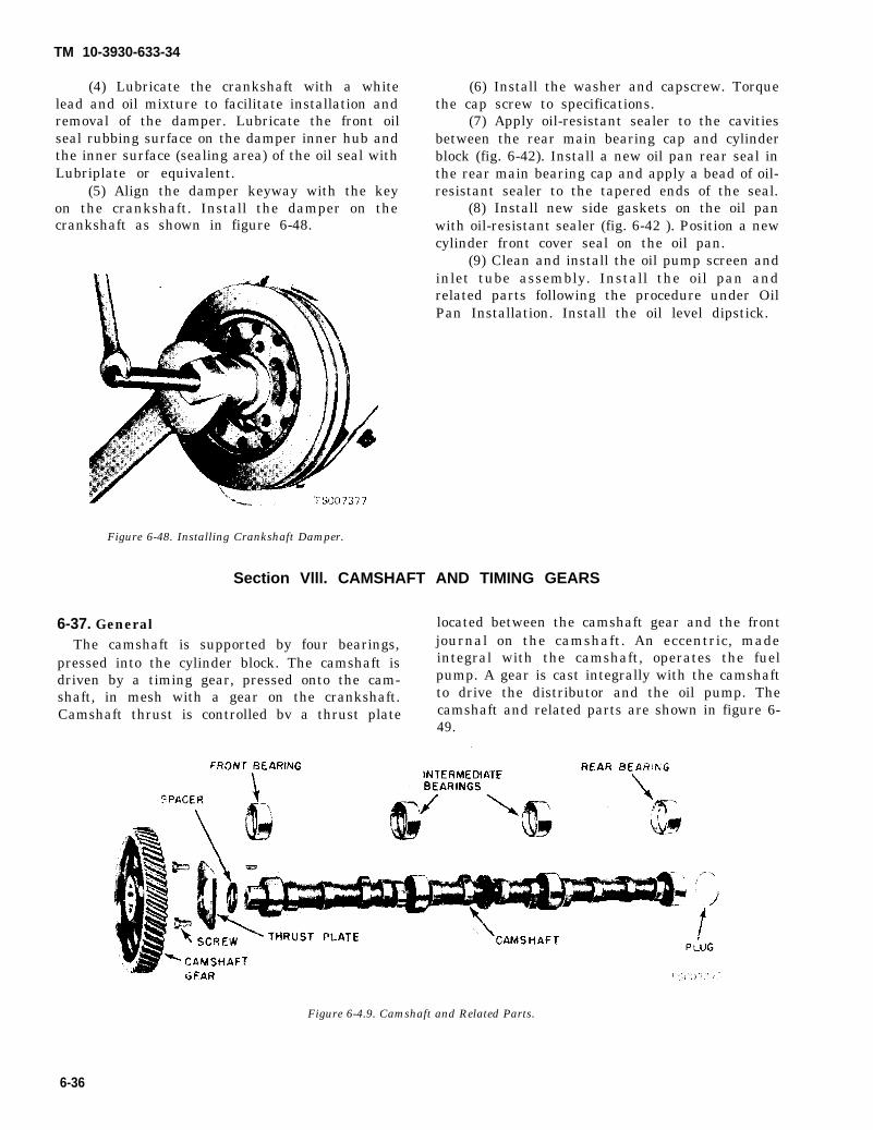
TM 10-3930-633-34
(4) Lubricate the crankshaft with a whitelead and oil mixture to facilitate installation andremoval of the damper. Lubricate the front oilseal rubbing surface on the damper inner hub andthe inner surface (sealing area) of the oil seal withLubriplate or equivalent.
(5) Align the damper keyway with the keyon the crankshaft. Install the damper on thecrankshaft as shown in figure 6-48.
(6) Install the washer and capscrew. Torquethe cap screw to specifications.
(7) Apply oil-resistant sealer to the cavitiesbetween the rear main bearing cap and cylinderblock (fig. 6-42). Install a new oil pan rear seal inthe rear main bearing cap and apply a bead of oil-resistant sealer to the tapered ends of the seal.
(8) Install new side gaskets on the oil panwith oil-resistant sealer (fig. 6-42 ). Position a newcylinder front cover seal on the oil pan.
(9) Clean and install the oil pump screen andinlet tube assembly. Install the oil pan andrelated parts following the procedure under OilPan Installation. Install the oil level dipstick.
Figure 6-48. Installing Crankshaft Damper.
Section Vlll. CAMSHAFT AND TIMING GEARS
6-37. General located between the camshaft gear and the front
The camshaft is supported by four bearings, journal on the camshaft. An eccentric, made
pressed into the cylinder block. The camshaft is integral with the camshaft, operates the fuel
driven by a timing gear, pressed onto the cam- pump. A gear is cast integrally with the camshaft
shaft, in mesh with a gear on the crankshaft. to drive the distributor and the oil pump. The
Camshaft thrust is controlled bv a thrust plate camshaft and related parts are shown in figure 6-49.
Figure 6-4.9. Camshaft and Related Parts.
6-36

6-38. Camshaft End Play and Timing GearChecks
a. End Play Check.(1) Remove the crankshaft damper and
cylinder front cover. (See procedures in SectionVII.)
(2) Push the camshaft toward the rear of theengine. Install a dial indicator so that the in-dicator point is on the camshaft gear attachingscrew (fig. 6-50).
TM 10-3930-633-34
(3) Zero the dial indicator. Position a largescrewdriver between the camshaft gear and theblock. Pull the camshaft forward and release it.Compare the dial indicator reading with thespecifications of table 6-7.
(4) If the end play is excessive, check thespacer for correct installation before it isremoved. If the spacer is correctly installed,replace the thrust plate.
(5) Remove the dial indicator.b. Timing Gear Backlash Check.
(1) Install a dial indicator on the cylinderblock as shown in figure 6-51.
Figure 6-50. Checking Camshaft End Play.
Figure 6-51. Checking Timing Gear Backlash.
Table 6-7. Camshaft and Timing Gear Specifications
ITEM lNCHESCAMSHAFT
Lobe lift - intake .. 0.2490L o b e l i f t - e x h a u s t Lobe lift - allowable wear
0.2490.0.005
End play . . . . .0.001-0.007End play - wear limit 0.009Journal to bearing clearance 0.001.0.003Journal to bearing clearance - wear limit 0.006Journal runout - maximum .0.008Journal out-of-round - maximum
BEARINGS0.005
Journal diameter - std 2.0170-2.0180Bearing inside diameter .2.0190-2.0200No. 1 bearing setback . .0.020-0.035
TIMING GEARBacklash 0.002-0.004C a m s h a f t g e a r f a c e r u n o u t 0.006 TIRCrankshaft gear face runout .0.003 TIR
(2) Turn the camshaft gear counterclockwise backlash reading. Refer to table 6-7 for backlashby hand to take up backlash and set the indicator limits.to zero with the plunger against one gear tooth. c. Timing Gear Runout.
(3) Hold the camshaft gear firmly against (1) Install dial indicator to the cylinder blockthe block and rotate the gear clockwise to obtain as shown in figure 6-52.
6-37

TM 10-3930-633-34
Figure 6-52. Checking Timing Gear Runout.
(2) Hold the camshaft gear against thethrust plate, and zero the indicator.
(3) Rotate the crankshaft to turn thecamshaft, while holding the camshaft gearagainst the thrust plate.
(4) Check gear runout through one completerevolution of the camshaft.
(5) If the gear runout exceeds specifications,remove it and check for burrs or foreign particleson or between the camshaft and gear joiningflanges. Check the runout. If it still exceedsspecifications, replace both gears.
(6) Follow the above procedure to checkcrankshaft gear runout.
6-39. Camshaft Removal and Installationa. Removal.
(1) Disconnect the spark plug wires at thespark plugs and disconnect the secondary hightension wire at the ignition coil. Remove thedistributor cap and spark plug wires as anassembly.
(2) Disconnect the fuel outlet lines at the fuelpump. Remove the fuel pump mounting bolts andposition the fuel pump out of the way.
(3) Disconnect the vacuum line at thedistributor and the primary wire at the coil.Remove the distributor.
(4) Remove the valve rocker arm cover.Loosen the rocker arm stud nuts, move the rockerarms to one side and remove the pushrods insequence. Place the pushrods in a rack so they canbe installed in their original locations.
(5) Remove the valve pushrod cover; thenremove the valve lifters in sequence, using thetool shown in figure 6-6. Place the valve lifters ina tray or rack to facilitate installation in the samesequence in which they were removed.
(6) Remove the capscrew and washer fromthe end of the crankshaft. Remove the damper(fig. 6-35).
(7) Remove the oil pan and related parts by ,following the procedure under paragraph 6-43.Remove the oil pump screen and inlet tubeassembly.
(8) Remove the cylinder front cover anddiscard the gasket.
(9) Check the camshaft end play, the timinggear backlash and the timing gear runout (para 6-38).
(10) Turn the crankshaft to align the timingmarks as shown in figure 6-36.
(11) Remove the camshaft thrust platescrews (fig. 6-53). Remove the camshaft. Avoiddamaging the camshaft lobes during removal.Press the camshaft out of the gear in an arborpress (fig. 6-54). Remove the key, thrust plateand spacer.
Figure 6-53. Thrust Plate Screws.
Figure 6-54. Removing Camshaft Gear.
6-38

TM 10-3930-633-34
b. Installation. If the camshaft end play,timing gear backlash and/or timing gear runoutwere excessive, make the necessary correctionsbefore installing the camshaft.
(1) Oil the camshaft bearing journals andapply Lubriplate or equivalent to all the lobes.
(2) Install the camshaft, gear and thrustplate as an assembly, making sure that the timingmarks are in alignment (fig. 6-36).
(3) Torque the thrust plate attaching screwsto specifications (see table 6-3).
(4) Position the camshaft gear on thecamshaft. Align the timing marks on the timinggears as shown in figure 6-36. Install the cam-shaft gear with the tool shown in figure 6-55. Besure the gear and spacer are tight against theshoulder on the camshaft.
Figure 6-55. Installing Camshaft Gear.
(5) Crank the engine until the timing marksare aligned. Do not turn the crankshaft againuntil the distributor is installed.
(6) Clean the cylinder front cover andcylinder block gasket surfaces. Install a new oilseal in the cylinder front cover. Clean thecrankshaft damper and inspect it, following theprocedures in paragraph 6-30. Install the cylinderfront cover and damper following paragraph 6-36.
(7) Clean the oil pump screen. Clean the oilpan and the gasket surfaces of the cylinder block.Install the oil pump screen and inlet tube and oilpan, following the procedures under Oil PanInstallation, paragraph 6-43.
(8) Lubricate the valve lifters with heavyengine oil and install the lifters (fig. 6-6) in thesame bores from which they were removed. ApplyLubriclate or equivalent to both ends of thepushrods and install the pushrods in the samesequence thatpushrods were
they were removed. Be sure theseated in the valve lifter sockets.
(9) Clean the valve pushrod cover andcylinder block gasket surfaces. Apply oil-resistant sealer to one side of a new gasket andplace the gasket on the pushrod cover with thecemented side next to the cover. Install the coverand torque the bolts in sequence to specifications.
(10) Apply Lubriplate or equivalent to thevalve pad on the rocker arms. Oil the valve stemswith heavy engine oil. Align the valve rockerarms with the valves and pushrods. Tighten therocker arm stud nuts sufficiently to hold thepushrods in place. Adjust the valve clearancefollowing instructions given in TM 10-3930-633-12.
(11) Clean the valve rocker arm cover andcylinder head gasket surface. Place the newgasket in the cover making sure that the tabs ofthe gasket engage the notches provided in thecover. Install the cover and torque the screws insequence to specifications.
(12) Set the distributor rotor so the points areabout to open for No. 1 cylinder firing position.Install the distributor. Check the points. If thecamshaft timing marks are still aligned (step 6above), the points should be fully open in No. 1cylinder firing posit ion. If the points are not open,remove the distributor and rotate the shaft in theproper direction. Install the distributor and hold-down clamp.
(13) Install the distributor cap and sparkplug wires as an assembly. Connect the sparkplug wires to the plugs and the secondary hightension wire to the coil.
6-40. Camshaft and Timing Gears Cleaning andInspection
a. Cleaning.(1) Clean the camshaft in a bath of solvent,
Federal Specification P-D-680, and wipe dry.(2) Clean timing gears in solvent bath and
dry with compressed air.b. Inspection.
(1) Inspect the gear teeth for scores, nicks,etc. Note the condition of the teeth contactpattern. If the teeth are scored, replace the gears.
(2) It is not necessary to replace the gears insets. Replace the camshaft gear and check thebacklash, runout, etc., to determine if thecrankshaft gear should be replaced.
(3) Inspect the camshaft lobes for scoringand signs of abnormal wear. Lobe wearcharacteristics may result in pitting in the generalarea of the lobe toe. This pitting is notdetrimental to the operation of the camshaft;therefore, the camshaft should not be replaced
6-39
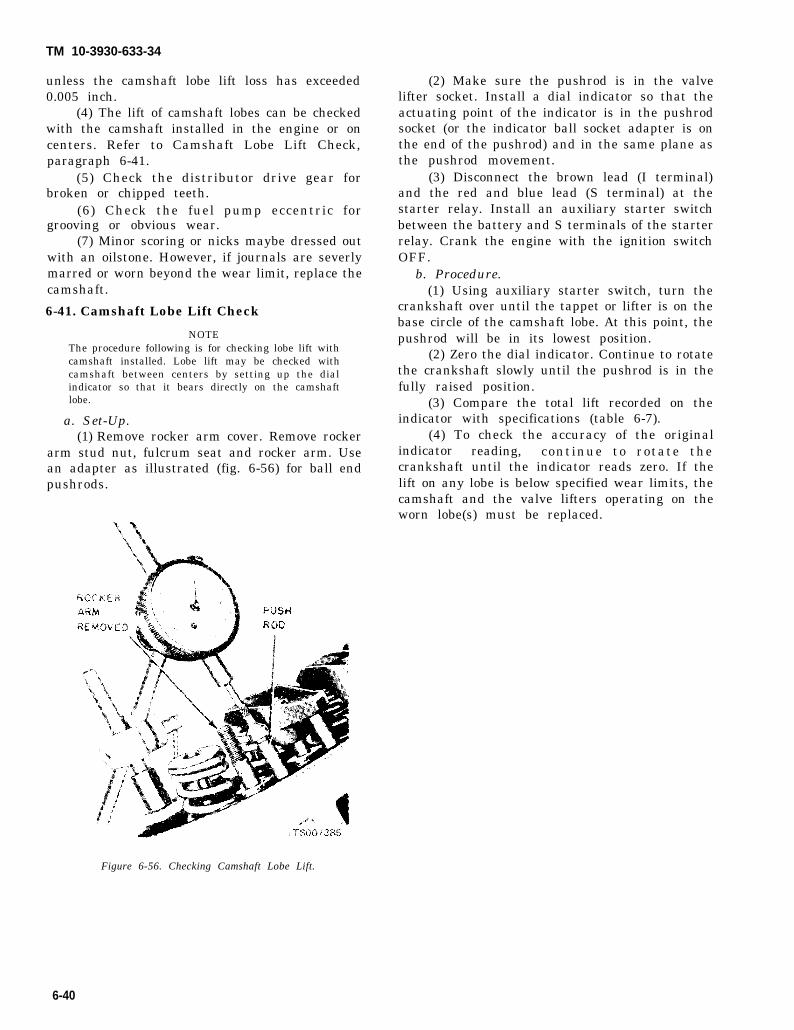
TM 10-3930-633-34
unless the camshaft lobe lift loss has exceeded0.005 inch.
(4) The lift of camshaft lobes can be checkedwith the camshaft installed in the engine or oncenters. Refer to Camshaft Lobe Lift Check,paragraph 6-41.
(5) Check the distributor drive gear forbroken or chipped teeth.
(6) Check the fuel pump eccentric forgrooving or obvious wear.
(7) Minor scoring or nicks maybe dressed outwith an oilstone. However, if journals are severlymarred or worn beyond the wear limit, replace thecamshaft.
6-41. Camshaft Lobe Lift Check
NOTEThe procedure following is for checking lobe lift withcamshaft installed. Lobe lift may be checked withcamshaft between centers by setting up the dialindicator so that it bears directly on the camshaftlobe.
a. Set-Up.(1) Remove rocker arm cover. Remove rocker
arm stud nut, fulcrum seat and rocker arm. Usean adapter as illustrated (fig.pushrods.
6-56) for ball end
(2) Make sure the pushrod is in the valvelifter socket. Install a dial indicator so that theactuating point of the indicator is in the pushrodsocket (or the indicator ball socket adapter is onthe end of the pushrod) and in the same plane asthe pushrod movement.
(3) Disconnect the brown lead (I terminal)and the red and blue lead (S terminal) at thestarter relay. Install an auxiliary starter switchbetween the battery and S terminals of the starterrelay. Crank the engine with the ignition switchOFF.
b. Procedure.(1) Using auxiliary starter switch, turn the
crankshaft over until the tappet or lifter is on thebase circle of the camshaft lobe. At this point, thepushrod will be in its lowest position.
(2) Zero the dial indicator. Continue to rotatethe crankshaft slowly until the pushrod is in thefully raised position.
(3) Compare the total lift recorded on theindicator with specifications (table 6-7).
(4) To check the accuracy of the originalindicator reading, continue to rotate thecrankshaft until the indicator reads zero. If thelift on any lobe is below specified wear limits, thecamshaft and the valve lifters operating on theworn lobe(s) must be replaced.
Figure 6-56. Checking Camshaft Lobe Lift.
6-40

TM 10-3930-633-34
Section IX. OIL PAN AND OIL PUMP
6-42. Generala. Oil from the oil pan sump is forced through
the pressure type lubrication system by the rotor-type oil pump. A spring loaded relief valve in thepump directs excess oil back to the intake side ofthe pump.
b. A full-flow disposable filter element filtersthe entire output of the pump before the oil entersthe engine. A by-pass valve permits flow aroundthe filter if it becomes clogged.
c. From the filter, oil flows into the main oilgallery. From this gallery oil is supplied to thecamshaft and main bearings, to each hydrauliclifter, to the crankshaft and connecting rods, andthe timing gears. A drilled passage in the blocksupplies oil to the distributor shaft, and the valvetrain is lubricated by oil from the lifter chamberpassing upward through the pushrods.
6-43. Oil Pan Removal and Installationa. Removal.
(1) Drain the crankcase.(2) Remove the oil pan attaching screws and
remove the oil pan,b. Installation.
(1) Clean the gasket surfaces of the oil pump,oil pan and cylinder block. Remove the rear mainbearing cap to oil pan seal and cylinder frontcover to oil pan seal. Clean the seal grooves.
(2) Apply oil-resistant sealer in the cavitiesbetween the bearing cap and cylinder block (fig.6-41). Install a new seal in the rear main bearingcap and apply a bead of oil-resistant sealer to thetapered ends of the seal.
(3) Install new side gaskets on the oil panwith oil resistant sealer (fig. 6-42). Position a newoil pan to cylinder front cover seal on the oil pan.
(4) Clean the inlet tube and screen assemblyand place it in the oil pan, if previously removed.
(5) Position the oil pan under the engine.Install the inlet tube and screen assembly on theoil pump with a new gasket. Torque the screws tospecifications. Position the oil pan against thecylinder block and install the attaching bolts.Torque the bolts in sequence to specifications. Seetable 6-3.
6-44. Oil Pump Removal and Installationa. Removal.
(1) Remove the oil pan as described inparagraph 6-43. The oil pump will be exposed asshown in figure 6-57.
Figure 6-57. Oil Pump Installed.
(2) Remove the oil pump attaching screwsand remove the pump from the cylinder block.
b. Installation.(1) Prime the oil pump by filling the inlet
opening with oil and rotate the pump shaft untiloil emerges from the outlet opening.
(2) Coat a new oil pump gasket with oil-resistant sealer and position it on the oil pump.
(3) Install the oil pump on the cylinder block.Torque the attaching bolts to specifications.
6-45. Oil Pump Repaira. Disassembly.
(1) Remove the cover attaching screws andremove the cover (fig. 6-58).
Figure 6-58. Oil Pump Disassembled.
6-41

TM 10-3930-633-34
(2) Remove the inner rotor “and shaftassembly, then remove the outer race.
(3) Scrape away the staking marks on thebody around the oil pressure relief valve cap. Drilla 1/8-inch hole in the relief valve cap and insert aself-threading sheet metal screw of properdiameter into the cap. Pull the cap out of thechamber. Remove the spring and plunger.
b. Cleaning. Wash all parts in a solvent and drythem thoroughly with compressed air. Use abrush to clean the inside of the pump housing andthe pressure relief valve chamber. Be sure all dirtand metal particles are removed.
c. Inspection.(1) Refer to table 6-8 for clearances and wear
limits.(2) Check the inside of the pump housing and
the outer race and rotor for damage or excessivewear or scoring.
(3) Check the mating surface of the pumpcover for wear. If the cover mating surface isworn, scored or grooved, replace the cover.
(4) Measure the outer race to housingclearance (fig. 6-59).
Figure 6-59. Measuring Outer Race Clearance.
Table 6-8. Oil Pump Specifications
ITEM SPECIFICATION
. — .
Relief valve spring tension . . . .20.6-22.6 lbat 2.490 length
Drive shaft-to-housing clearance 0.0015-0.0029 in.Relief valve clearance . . . . 0.0015-0.0029inRotor end play . . . . . . . . . . . . . . ...0.0010-0.00409.O u t e r r a c e - t o - h o u s i n g c l e a r a n c e . . . . . . . . 0 . 0 0 1 - 0 . 0 1 3 i n .
(5) With the rotor assembly installed in thehousing, place a straightedge over the rotorassembly and the housing. Measure the clearance(rotor end play) between the straightedge and therotor and outer race (fig. 6-60). The outer race,shaft and rotor are replaceable only as anassembly.
Figure 6-60. Measuring Rotor End Play.
6-42
TM 10-3930-633-34
(6) Check the drive shaft to housing bearingclearance by measuring the OD of the shaft andthe ID of the housing bearing.
(7) Inspect the relief valve spring for acollapsed or worn condition. Check the relief valvespring tension. If the spring tension is not withinspecifications and/or the spring is worn ordamaged, replace the spring.
(8) Check the relief valve piston for scoresand free operation in the bore.
d. Assembly.(1) Clean all parts thoroughly. Install the oil
pressure relief valve plunger, spring and new cap.Stake the cap into position.
(2) Install the outer race (recessed dot facingout on same side as dot on rotor) and the innerrotor and shaft assembly.
NOTEThe inner rotor and shaft and the outer race areserviced as an assembly. One part should not bereplaced without replacing the other.
6-46. Oil Pan Cleaning and Inspectiona. Cleaning.
(1) Scrape any dirt or metal particles frominside the pan.
(2) Scrape all gasket material from mountingflange.
(3) Wash the pan in solvent, FederalSpecification P-D-680, and dry thoroughly.
NOTEMake certain that all foreign particles are removedfrom below the baffle plate.
b. Inspection.(1) Check the pan for cracks, holes, damaged
drain plug threads, and a loose baffle. Check thegasket surface for damage caused by overtorquedbolts. Straighten the surface as required torestore original flatness.
(2) Replace the pan if repairs cannot be made.
(3) Install the cover and torque the attachingscrews to specifications.
6-43


TM 10-3930-633-34
CHAPTER 7
REPAIR OF TRANSMISSION ASSEMBLY
Section 1. DESCRIPTION
7-1. General b. The transmission consists essentially of aa. The transmission is a two speed unit capable torque converter, planetary gear train, two
of providing automatic upshifts and downshifts multiple disc clutches and a hydraulic controlthrough the two forward gear ratios, and also system. Figure 7-1 shows all the components ofcapable of providing manual selection of first and the transmission.second gears.
Figure 7-1. Transmission Cutaway.
7-2. Operation (2) The converter torque multiplicationa. Torque Converter. The hydraulic torque gradually tapers off as turbine speed approaches
converter consists of an impeller (pump), a impeller speed, and it becomes 1 to 1 when theturbine, and a stator. AU these parts are enclosed turbine is being driven at 9/10 impeller speed.and operate in a fluid-filled housing. This is known as the coupling point.
(1) When the engine is running, the fluid in (3) When the turbine is rotating at less thanthe torque converter flows from the impeller to 9/10 impeller speed, the converter is multiplyingthe turbine and back to the impeller through the torque. The fluid leaving the turbine bladesstator. This flow produces a maximum torque strikes the front face of the stator blades. Theseincrease of about 2 to 1 when the turbine is blades are held stationary by the action of a one-stalled. When enough torque is developed by the way clutch as long as the fluid is directed againstimpeller, the turbine begins to rotate, turning the the front face of the blades.turbine shaft. (4) When the turbine rotates faster than 9/10
7-1

TM 10-3930-633-34
impeller speed, the converter no longer multipliestorque. The fluid is directed against the back faceof the stator blades. As the one-way clutchpermits the stator to rotate only in the directionof impeller rotation, the stator begins to turn withthe impeller and turbine. The converter operatesas an efficient fluid coupling as long as the turbinespeed remains greater than 9/10 impeller speed.
(5) A constant flow of fluid into and out ofthe converter is maintained. Some of the fluidcoming out of the converter is forced through acooler located in the radiator tank.
b. Planetary Gear Train. The planetary geartrain consists of a primary sun gear, secondarysun gear, primary and secondary pinions whichare held in a common carrier, and an internal gearto which the transmission output shaft is at-tached.
c. Front Clutch. The front clutch drive platesare connected to the turbine shaft through thefront clutch drum. The driven plates are con-nected to the primary sun gear shaft.
(1) The front clutch is operated by fluid
pressure against the clutch piston. The pistonmoves against a disc spring which acts as a leverto lock the drive and driven plates together.When the clutch is applied, the primary sun gearis locked to and driven by the turbine shaft. Thepiston is returned to the release position by thedisc spring when the fluid pressure is removed. Acheck ball is installed in the front clutch piston topermit fluid exhaust, when the piston is in itsreleased position.
(2) In neutral, the front clutch drum and steelplates are being driven while the compositionplates are stationary. In reverse, the clutch is notapplied, since the steel and composition platesmust rotate in opposite directions. See table 7-1for Clutch Applications.
d. Rear Clutch. The rear clutch is operated byfluid pressure against the clutch piston.Movement of the piston compresses the releasespring and locks the multiple-disc clutch. Therear clutch drive plates are splined to the frontclutch drum and the driven plates are connectedto the rear clutch drum and secondary sun gear.
Table 7-1, Clutch Applications
Gear Selector Lever Clutch BandPosition
GearApplied Applied Ratio
N e u t r a l . . N . . . . . N o n e . . . . N o n eL . D . . . . . . . . . . . . . . . . . . Front Front . .1.47:1H i g h . D . . . . . . . . . . . . .. Front and Rear. . .. None. .1.00:1Reverse . . . . . . . . R . R e a r . . . . . . R e a r . . 2 . 0 0 : 1
(1) When the rear clutch is applied (in thereverse and third gear ratios) the secondary sungear is driven. The piston is returned to thereleased position by the release spring.
(2) In neutral, the rear clutch compositionplates are being driven while the steel plates arefree. In second gear, the composition plates aredriven, but the steel plates are held stationary. Infirst gear, the composition plates are drivenclockwise at engine speed while the steel platesare driven counterclockwise. See table 7-1 forclutch applications.
e. Front Band and Servo. One end of the frontband, which encircles the rear clutch drum, isanchored to the transmission case, and the otherend is connected to the front servo.
(1) Fluid pressure moves the front servopiston against the inner end of the front servoactuating lever. Force is transmitted through astrut between the outer end of the lever and the
end of the band to tighten the band around therear clutch drum.
(2) Under certain conditions, the servo isreleased by directing fluid pressure to the op -posite side of the piston, assisted by releasespring force.
f. Rear Band and Servo. The rear band fitsaround the planetary gear drum. One end of theband contacts the end of the band adjustingscrew, and the other end connects to the rearservo.
7-3. Hydraulic Control SystemOperation of the servos and clutches is ac-
complished by directing hydraulic fluid undervarious pressures through the control valve body.The levels of these pressures are determined asoutlined in the following paragraphs. Refer tofigure 7-2 for a schematic of the hydraulic controlsystem.
7-2

TM 10-3930-633-34
Figure 7-2. Hydraulic Control,System.
a. Control Pressure and Compensator Pressure. (2) To accomplish this, compensator pressure(1) Control pressure is regulated by the under various conditions is adjusted by throttle
spring-loaded control pressure regulator valve. It pressure (engine torque), governor pressure (roadis adjusted to engine torque, road speed, and speed), or selector lever position. Compensatorselector lever position. pressure, in turn, adjusts control pressure.
7-3

TM 10-3930-633-34
b. Converter Pressure. Like control pressure,converter pressure is regulated by the converterpressure regulator valve spring and is adjusted todriving conditions by compensator pressure andselector lever positions.
c. Manual Valve. Line pressure is delivered tothe manual valve through a single passage; thevalve is positioned in the valve body by themanual linkage, according to the mode ofoperation desired. Fluid is distributed from themanual valve through the following passages.
(1) The D passage–charged in D range only.The D passage supplies fluid to the downshiftvalve, and through the 1-2 shift shuttle ball checkvalve to the 1-2 shift valve. In addition, fluid isdirected to the 2-3 shift orifice and through it tothe 2-3 shift valve and to the bottom of the rearservo lockout valve.
(2) The D-2-1 passage–charged in Driverange, manual Second gear (2 range) and manuallow gear (1 range). The D-2-1 passage directsapply fluid to the forward clutch, applying it, andto the upper end of the transition valve, to thegovernor valve and to the compensator cut backvalve.
(3) The 2-1-R-P passages–charged in 2, 1and Reverse. The 2-1-R-P passage supplies fluidto the upper valley of the 1-2 shift valve, andpasses through the 1-2 shift valve bore to theadj scent ends of the 1-2 shift accumulator andlockout valves.
(4) The 1-R-P passages–charged in 1, andReverse. The 1-R-P passage supplies fluid to thevalley of the 2-1 scheduling valve and through the1-2 shift shuttle ball check valve to the 1-2 shiftvalve.
(5) The R Passage– charged in R range only.The R passage supplies fluid to the left valley ofthe throttle valve and to the upper valley of the 2-3 shift valve.
d. Throttle Pressure.(1) Throttle pressure adjusts the trans-
mission operation to engine torque. Throttlepressure is produced from control pressure by thethrottle valve. The throttle valve is controlled bya spring-loaded vacuum diaphragm unit mountedon the rear of the transmission case.
(2) The vacuum diaphragm is actuated by theengine intake manifold vacuum working againstspring pressure. When the vacuum is higher than16 inches, the diaphragm moves against springpressure and moves the pushrod away from thethrottle valve to cut off the throttle pressureregulation. As the engine throttle is advanced,manifold vacuum will fall below 16 inches. As the
vacuum drops, the spring-loaded diaphragmmoves the pushrod to open the throttle valve andincrease the throttle pressure.
e. Neutral.(1) The manual valve at N selector lever
position blocks the fluid flow to both clutches andboth bands. With no fluid pressure in the clutchesor servos, the clutches and bands are released byspring pressure, preventing power being trans-mitted to the transmission output shaft.
(2) Neutral operation of the transmissionkeeps control pressure up to its proper value,maintains a full torque converter, lubricates thetransmission, and maintains a flow of fluidthrough the cooling system.
f. D, Low Gear.(1) The 1-2 shift occurs when governor
pressure force on the 1-2 shift valve overcomesshift plug pressure and spring forces. The 1-2valve moves inward, exhausting the fluid whichholds the transition valve closed. The transitionvalve opens and admits control pressure to applythe front band.
(2) The front clutch remains on, and the frontband applied to put the transmission in secondgear.
g. D, High Gear. The 2-3 shift occurs whengovernor pressure force overcomes spring andshift plug pressure force at the 2-3 shift valve.When the shift valve opens, control pressureflows through it to apply the rear clutch andrelease the front band. With both clutches ap-plied, the transmission is in third gear.
h. Low Gear.(1) When the manual valve is at the 2 selector
lever position, control pressure to the 1-2 shiftvalve is cut off. This condition permits controlpressure to flow through the transition valve toapply the front band.
(2) With the front clutch and the front bandapplied, the transmission operates in first gear.
i. D Range, 2-1 Kickdown. When the ac-celerator pedal is depressed through the detent,the down-shift valve opens a passage that admitscontrol pressure behind the 1-2 shift plug tooppose governor pressure. If the transmission isin high and road speed is below 47-69 mph, the 2-3valve will be forced closed against governorpressure. When the 2-3 valve closes, controlpressure which has been applying the rear clutchand releasing the front band is exhausted. Theapply pressure that was in the front servo in thirdgear is now free to apply the front band. As soonas the front band applies, the transmission is insecond gear.
7-4

TM 10-3930-633-34
j. Reverse. When the manual valve is shifted through the oil cooler, then the cooled fluid isinto reverse, control pressure is directed to apply used in the transmission lubricating circuit.the rear clutch and rear band. Governor supply (2) A spring-loaded check valve is used in thepressure is cut off by the manual valve; hence, the circuit to maintain about 3-5 PSI in the convertertransmission cannot shift automatically. Rear out circuit. When the converter out circuit ex-clutch pressure is also directed to the throttle ceeds 3-5 PSI, the check ball opens against springvalve to regular throttle pressure to obtain the pressure and cooledcorrect line pressure for the reverse circuit. the various parts of
k. Fluid Cooling and Lubricating System.(1) The converter out circuit is directed
Section Il. ADJUSTMENTS AND TESTS
7-4. GeneralPrior to removal of the transmission from the
vehicle for disassembly or repair, make certainthat a band adjustment as outlined below is notthe cause of malfunction. The tests outlined in thefollowing paragraphs will aid in determining theexact cause of the malfunction.
7-5. Band Adjustmentsa. Front Band Adjustment.
(1) Drain the fluid from the transmission. Ifthe same fluid is to be used again in the trans-mission after the band adjustment, filter thefluid through a 100-mesh screen as it drainsfrom the transmission. Reuse the fluid only if it isin good condition.
(2) Remove the pan, then remove the fluidfilter and clip from the transmission. Clean theinside of the pan. Remove all gasket materialfrom the pan and pan mounting face of the case.
(3) Loosen the front servo adjusting screwlockut two full turns with a 9/16 inch wrench.Check the adjusting screw for free rotation in theactuating lever after the locknut is loosened, andfree the screw if necessary. See figure 7-3.
fluid is directed to lubricatethe transmission gear train.
Figure 7-3. Front Band Adjustment.
(4) Pull the adjusting screw end of the ac-tuating lever away from the servo body, andinsert the ½ inch spacer between the servo pistonstem and the adjusting screw.
7-5

TM 10-3930-633-34
(5) Install the socket handle on the 9/16 inchsocket.
(6) Insert the T-handle extension through thesocket handle and socket, and install thescrewdriver socket on the T-handle extension.
(7) Place the tool on the adjusting screw sothat the screwdriver socket engages the screw andthe 9/16 inch socket engages the locknut.
(8) With a torque wrench on the T-handleextension, tighten the adjusting screw to 10in./lbs torque.
(9) Remove the spacer and tighten the ad-justing screw an additional ¾ turn. Hold theadjusting screw stationary, and torque thelocknut to specification.
(10) Place a new gasket on the pan, andinstall the screen and pan on the transmission.
(11) Fill the transmission with fluid. See LO10-3930-633-12.
b. Rear Band Adjustment.(1) Remove all dirt from adjusting screw and
surrounding area. See figure 7-4.
Figure 7-4. Rear Band Adjustment.
(2) Loosen the adjusting screw locknut with abox end wrench as shown in the illustration.
(3) Using a torque wrench, tighten the ad-justing screw to 10 ft/lbs. Try to get the ad-justment as close to exactly 10 ft/lbs as possible.
(4) If the screw is found to be tighter thanwrench capacity (10 ft/lbs torque), loosen the
screw and tighten until the wrench clicks andbreaks.
(5) Back off the adjusting screw 1-½ turns.Hold the adjusting screw stationary and tightenthe adjusting screw locknut to specification.Severe damage may result if the adjusting screwis not backed off exactly 1 ½ turns.
7-6. Stall Testa. Start the engine to allow it to reach its
normal temperature. Apply both the parking andservice brakes while making tests.
b. The stall test is made in D, or R, at fullthrottle to check engine performance, converterclutch operation or installation, and the holidayability of the forward clutch, reverse-high clutchand low-reverse band and the gear train one-wayclutch. While making this test, do not hold thethrottle open for more than five seconds at a time.Then move the selector lever to Neutral and runengine at 1000 RPM for about 15 seconds to coolthe converter before making the next test. If theengine speed recorded by the tachometer exceedsthe maximum limits, 1300 to 1500 RPM, releasethe accelerator immediately because clutch orband slippage is indicated.
7-7. Control Pressure Checksa. When performing control pressure checks,
make certain that the engine is at normaloperating temperature and that timing andcarburetor are properly adjusted. Set parkingbrake firmly to prevent vehicle motion. Checkmanifold vacuum (see Chapter 6) to make certaina reading of 18 inches (Hg) is obtained at engineidle. At higher altitudes, it may not be possible toobtain 18 inches of vacuum; under these con-ditions, use the chart in the lower part of table 7-2to adjust pressure readings in proportion to thelower vacuum readings. Make certain, however,that the lower vacuum reading is not due to a leakin the transmission or distributor vacuum line.
b. With vacuum readings and engine ad-justments verified, connect a pressure gage of O-250 PSI range to the control pressure port shownin figure 7-5, and proceed with test as follows:
7-6

Table 7-2.
TM 10-3930-633-34
Control Pressure Checks
Engine Vacuum Line Pressure17 inches 57-7716 inches ..57-8215 inches .57-8814 inches 57-9513 inches 57-10212 inches .57-10811 inches .57-115
Figure 7-5. Control Pressure Port.
(1) At engine idle check control pressurereadings in all selector lever positions.
(2) Advance throttle to obtain 10 inches ofvacuum, and check pressure readings in allselector lever positions.
(3) Advance throttle to obtain 1.0 inches orless, and check pressure readings in all selectorlever positions.
(4) Compare readings with those given intable 7-2. If vacuum and pressure readings arewithin specifications, the diaphragm unit andcontrol pressure regulating system are operatingproperly. If control pressures are not withinspecifications, refer to table 7-3 for causes ofabnormal reading.
Table 7-3. Abnormal Pressure Reading Diagnosis
Engine Vacuum Control PressureReading (In. / Hg) Level Possible Causes
I
18 L o w Front oil pump leakageControl valve leakageControl pressure regulator sticking
High Defective diaphragm unit10 High Internal leakageand or Low pump capacity (wear)1.0 or less Low Restricted oil pan screen
Defective diaphragm unit
7-8. Air Pressure Checks at 2, a NO DRIVE condition may be caused by anA “NO DRIVE” condition can exist, even with inoperative forward clutch. A NO DRIVE con-
correct fluid control pressure, because of dition at D may be caused by an inoperativeinoperative clutches or bands. Erratic shifts could forward clutch or one-way clutch. When there isbe caused by a stuck governor valve. The NO DRIVE in 1, the difficulty could be caused byinoperative units can be located through a series improper functioning of the forward clutch or low-of checks by substituting air pressure for the reverse band and the one-way clutch. Failure tofluid pressure to determine the location of the drive in reverse range could be caused by amalfunction. malfunction of the reverse-high clutch or low-
a. Clutch Failures. When the selector lever is reverse band.
7-7
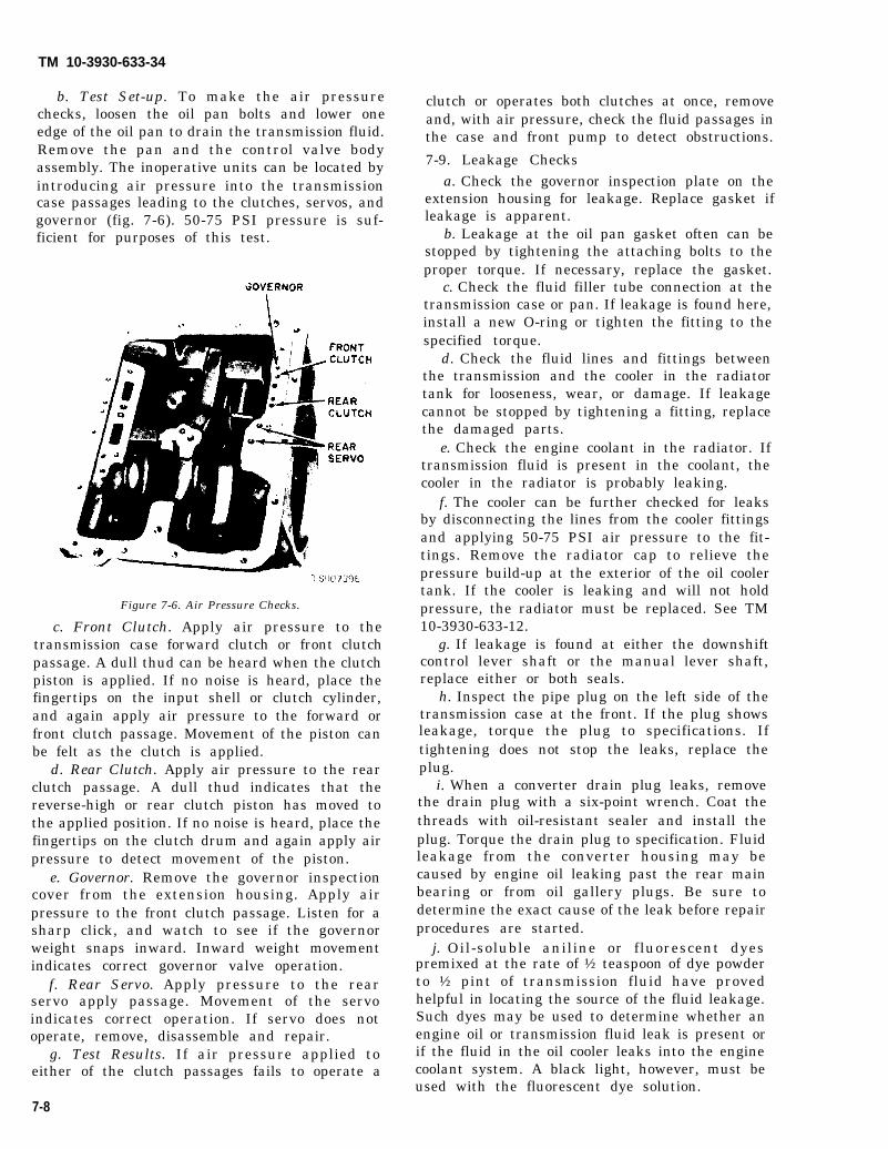
TM 10-3930-633-34
b. Test Set-up. To make the air pressurechecks, loosen the oil pan bolts and lower oneedge of the oil pan to drain the transmission fluid.Remove the pan and the control valve bodyassembly. The inoperative units can be located byintroducing air pressure into the transmissioncase passages leading to the clutches, servos, andgovernor (fig. 7-6). 50-75 PSI pressure is suf-ficient for purposes of this test.
Figure 7-6. Air Pressure Checks.
c. Front Clutch. Apply air pressure to thetransmission case forward clutch or front clutchpassage. A dull thud can be heard when the clutchpiston is applied. If no noise is heard, place thefingertips on the input shell or clutch cylinder,and again apply air pressure to the forward orfront clutch passage. Movement of the piston canbe felt as the clutch is applied.
d. Rear Clutch. Apply air pressure to the rearclutch passage. A dull thud indicates that thereverse-high or rear clutch piston has moved tothe applied position. If no noise is heard, place thefingertips on the clutch drum and again apply airpressure to detect movement of the piston.
e. Governor. Remove the governor inspectioncover from the extension housing. Apply airpressure to the front clutch passage. Listen for asharp click, and watch to see if the governorweight snaps inward. Inward weight movementindicates correct governor valve operation.
f. Rear Servo. Apply pressure to the rearservo apply passage. Movement of the servoindicates correct operation. If servo does notoperate, remove, disassemble and repair.
g. Test Results. If air pressure applied toeither of the clutch passages fails to operate a
clutch or operates both clutches at once, removeand, with air pressure, check the fluid passages inthe case and front pump to detect obstructions.
7-9. Leakage Checksa. Check the governor inspection plate on the
extension housing for leakage. Replace gasket ifleakage is apparent.
b. Leakage at the oil pan gasket often can bestopped by tightening the attaching bolts to theproper torque. If necessary, replace the gasket.
c. Check the fluid filler tube connection at thetransmission case or pan. If leakage is found here,install a new O-ring or tighten the fitting to thespecified torque.
d. Check the fluid lines and fittings betweenthe transmission and the cooler in the radiatortank for looseness, wear, or damage. If leakagecannot be stopped by tightening a fitting, replacethe damaged parts.
e. Check the engine coolant in the radiator. Iftransmission fluid is present in the coolant, thecooler in the radiator is probably leaking.
f. The cooler can be further checked for leaksby disconnecting the lines from the cooler fittingsand applying 50-75 PSI air pressure to the fit-tings. Remove the radiator cap to relieve thepressure build-up at the exterior of the oil coolertank. If the cooler is leaking and will not holdpressure, the radiator must be replaced. See TM10-3930-633-12.
g. If leakage is found at either the downshiftcontrol lever shaft or the manual lever shaft,replace either or both seals.
h. Inspect the pipe plug on the left side of thetransmission case at the front. If the plug showsleakage, torque the plug to specifications. Iftightening does not stop the leaks, replace theplug.
i. When a converter drain plug leaks, removethe drain plug with a six-point wrench. Coat thethreads with oil-resistant sealer and install theplug. Torque the drain plug to specification. Fluidleakage from the converter housing may becaused by engine oil leaking past the rear mainbearing or from oil gallery plugs. Be sure todetermine the exact cause of the leak before repairprocedures are started.
j. Oil-soluble aniline or fluorescent dyespremixed at the rate of ½ teaspoon of dye powderto ½ pint of transmission fluid have provedhelpful in locating the source of the fluid leakage.Such dyes may be used to determine whether anengine oil or transmission fluid leak is present orif the fluid in the oil cooler leaks into the enginecoolant system. A black light, however, must beused with the fluorescent dye solution.
7-8

TM 10-3930-633-34
Section Ill. TRANSMISSION REPAIRS
7-10. General provided in the following paragraphs, underTransmission repairs involve the systematic separate headings. Refer to figure 7-7 for general
disassembly, cleaning, inspection and repair of all parts identification during the disassemblytransmission subassemblies. The specific procedure.procedures covering these subassemblies are
7-9
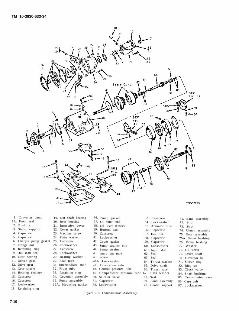
TM 10-3930-633-34
1. Converter pump1A. Front seal2. Bushing3. Stator support4. Capscrew5. Capscrew6. Charger pump gasket7. Flange nut8. Retaining ring9. Out shaft seal
10. Gear bearing11. Driven gear12. Drive gear13. Gear spacer14. Bearing retainer15. Capscrew16. Capscrew17. Lockwasher18. Retaining ring
19. Out shaft bearing20. Rear housing21. Inspection cover22. Cover gasket23. Machine screw24. Plain washer25. Capscrew26. Lockwasher27. Capscrew28. Lockwasher29. Bearing washer30. Rear tube31 Intermediate tube32. Front tube33. Retaining ring34, Governor assembly35. Pump assembly35A. Mounting gasket
36.37.38.39.40.41.42.43.44.45.46.
Pump gasketOil filler tubeOil level dipstickBottom panCapscrewLockwasherCover gasketSump strainer clipSump strainerpump out tubeScrew
53. Capscrew54. Lockwasher55. Actuator tube56. Capscrew57. Hex nut58. Capscrew59. Capscrew60. Lockwasher61. Input shaft62. Seal63. Seal
46A. Lockwasher 64. Thrust washer47. Lubrication tube 65. Drive shaft48. Control pressure tube 66. Thrust race49. Compensator pressure tube 67. Plain washer50. Selector valve 68. Seal51. Capscrew 69. Band assembly52. Lockwasher 70. Center support
71. Band assembly72. Strut73. Strut74. Clutch assembly75. Gear assembly75A. Front bushing76. Drum bushing77. Washer78. Oil sleeve79. Drive shaft80. Governor ball81. Sleeve ring82. Ring set83. Check valve84. Shaft bushing85. Transmission case86. Case bolt87. Lockwasher
Figure 7-7. Transmission Assembly.
7-10

TM 10-3930-633-34
7-11. Torque Convertera. General. The torque converter is mounted
on the input end of the transmission and consistsof an impeller, stator turbine and converterclutch .
b. Removal. The torque converter andtransmission are separated upon removal of thetransmission from the engine. Refer to Chapter 2,Section IV. The torque converter can be simplylifted from the converter housing upon removal ofthe housing from the engine. The torque con-verter is not repairable and must be replacedcomplete.
c. Cleaning. When internal wear or damagehas occurred in the transmission, metal particles,clutch plate or band material may have beencarried into the converter. These contaminantsare a major cause of recurring transmissiontroubles and MUST be removed from the systembefore the transmission is put back into service.The converter must be cleaned by using amechanically agitated cleaner.
d. Stator to Impeller Interference Check.(1) Position the front pump assembly on a
bench with the spline end of the stator shaftpointing up.
(2) Mount a converter on the pump so thatthe splines on the one-way clutch inner race.engage the m sting splines of the stator support,and the converter hub engages the pump drivegear.
(3) While holding the pump stationary, tryto rotate the converter counterclockwise. Theconverter should rotate freely without any signsof interference or scraping within the converterassembly.
(4) If there is an indication of scraping, thetrailing edges of the stator blades may be in-terfering with the leading edges of the impellerblades. In such cases, replace the converter.
(5) If interference exists, the stator frontthrust washer may be worn, allowing the stator tohit the turbine. In such cases, the converter mustbe replaced.
(6) The converter crankshaft pilot should bechecked for nicks or damaged surfaces that could .cause interference when installing the converterinto the crankshaft. Check the converter frontpump drive hub for nicks or sharp edges thatwould damage the pump seal.
e. Stator to Turbine Interference Check.(1) Position the converter on the bench front
side down.(2) Install a front pump assembly to engage
the mating splines of the stator support andstator, and pump drive gear lugs.
(3) Install the input shaft, engaging thesplines with the turbine hub.
(4) While holding the pump stationary,attempt to rotate the turbine with the input shaft.The turbine should rotate freely in both directionswithout any signs of interference or scrapingnoise.
f. Installation.(1) Carefully position the converter and
housing to the transmission making sure theconverter drive flats are fully engaged in thepump gear. Install a wedge to prevent the con-verter from slipping out of the housing.
(2) Refer to Chapter 2, Section IV fortransmission assembly installation.
7-12. Transmission Disassembly andReassembly
a. Disassembly.(1) Before removing any of the transmission
subassemblies, thoroughly clean the outside ofthe transmission case to prevent dirt from gettinginside the mechanism.
(2) After the transmission has been removedfrom the vehicle, disconnect the oil cooler lines atthe transmission. Place the unit in a work standor on a clean bench.
(3) Remove the transmission pan, gasket,and screen retainer clip.
(4) Lift the screen from the case.(5) Remove the spring seat from the pressure
regulator. Maintain constant pressure on the seatto prevent distortion of the spring seat and thesudden release of the springs. Remove thepressure regulator springs and pilots, but do notremove valves.
(6) Remove the small compensator pressuretube from the pressure regulator and the controlvalve body.
(7) Remove the main pressure oil tube first,by gently prying up the end that connects to themain control valve assembly, then, remove theother end of the tube from the pressure regulator.Be sure to remove the tube in this manner.Failure to do so could kink or bend the tubecausing excessive transmission internal leakage.
(8) Loosen the front and rear servo bandadjusting screws five turns. Loosen the frontservo attaching bolts three turns.
(9) Remove the vacuum diaphragm unit andpushrod.
(10) Remove the control valve body at-taching bolts. Align the levers to permit removalof the valve body. Then lift the valve body clear ofthe transmission case. Pull the body off the servotubes and remove it from the case.
7-11
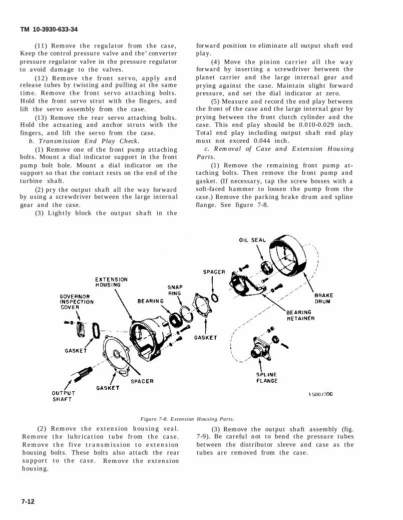
TM 10-3930-633-34
(11) Remove the regulator from the case,Keep the control pressure valve and the’ converterpressure regulator valve in the pressure regulatorto avoid damage to the valves.
(12) Remove the front servo, apply andrelease tubes by twisting and pulling at the sametime. Remove the front servo attaching bolts.Hold the front servo strut with the fingers, andlift the servo assembly from the case.
(13) Remove the rear servo attaching bolts.Hold the actuating and anchor struts with thefingers, and lift the servo from the case.
b. Transmission End Play Check.(1) Remove one of the front pump attaching
bolts. Mount a dial indicator support in the frontpump bolt hole. Mount a dial indicator on thesupport so that the contact rests on the end of theturbine shaft.
(2) pry the output shaft all the way forwardby using a screwdriver between the large internalgear and the case.
(3) Lightly block the output shaft in the
forward position to eliminate all output shaft endplay.
(4) Move the pinion carrier all the wayforward by inserting a screwdriver between theplanet carrier and the large internal gear andprying against the case. Maintain slight forwardpressure, and set the dial indicator at zero.
(5) Measure and record the end play betweenthe front of the case and the large internal gear byprying between the front clutch cylinder and thecase. This end play should be 0.010-0.029 inch.Total end play including output shaft end playmust not exceed 0.044 inch.
c. Removal of Case and Extension HousingParts.
(1) Remove the remaining front pump at-taching bolts. Then remove the front pump andgasket. (If necessary, tap the screw bosses with asoft-faced hammer to loosen the pump from thecase.) Remove the parking brake drum and splineflange. See figure 7-8.
Figure 7-8. Extension Housing Parts.
(2) Remove the extension housing seal. (3) Remove the output shaft assembly (fig.Remove the lubrication tube from the case. 7-9). Be careful not to bend the pressure tubesRemove the five transmission to extension between the distributor sleeve and case as thehousing bolts. These bolts also attach the rear tubes are removed from the case.support to the case. Remove the extensionhousing.
7-12
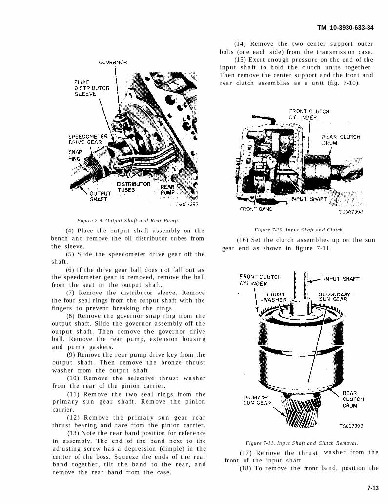
TM 10-3930-633-34
Figure 7-9. Output Shaft and Rear Pump.
(4) Place the output shaft assembly on thebench and remove the oil distributor tubes fromthe sleeve.
(5) Slide the speedometer drive gear off theshaft.
(6) If the drive gear ball does not fall out asthe speedometer gear is removed, remove the ballfrom the seat in the output shaft.
(7) Remove the distributor sleeve. Removethe four seal rings from the output shaft with thefingers to prevent breaking the rings.
(8) Remove the governor snap ring from theoutput shaft. Slide the governor assembly off theoutput shaft. Then remove the governor driveball. Remove the rear pump, extension housingand pump gaskets.
(9) Remove the rear pump drive key from theoutput shaft. Then remove the bronze thrustwasher from the output shaft.
(10) Remove the selective thrust washerfrom the rear of the pinion carrier.
(11) Remove the two seal rings from theprimary sun gear shaft. Remove the pinioncarrier.
(12) Remove the primary sun gear rearthrust bearing and race from the pinion carrier.
(13) Note the rear band position for referencein assembly. The end of the band next to theadjusting screw has a depression (dimple) in thecenter of the boss. Squeeze the ends of the rearband together, tilt the band to the rear, andremove the rear band from the case.
(14) Remove the two center support outerbolts (one each side) from the transmission case.
(15) Exert enough pressure on the end of theinput shaft to hold the clutch units together.Then remove the center support and the front andrear clutch assemblies as a unit (fig. 7-10).
Figure 7-10. Input Shaft and Clutch.
(16) Set the clutch assemblies up on the sungear end as shown in figure 7-11.
Figure 7-11. Input Shaft and Clutch Removal.
(17) Remove the thrustfront of the input shaft.
(18) To remove the front
washer from the
band, position the
7-13

TM 10-3930-633-34
band ends between the case webbing and tilt thebottom of the band rearward. Then, squeeze theends of the band together and remove from therear of the case.
(19) Lift the front clutch assembly from theprimary sun gear shaft.
(20) Remove the bronze and the steel thrustwashers from the rear clutch assembly; wire thethrust washers together to assure correct in-stallation.
(21) Remove the front clutch seal rings fromthe primary sun gear shaft.
(22) Lift the rear clutch assembly from theprimary sun gear shaft.
(23) Remove the rear clutch seal rings fromthe primary sun gear shaft. Do not break the sealrings.
(24) Remove the primary sun gear frontthrust washer.
d. Assembly. Do not use force to assemblemating parts. If the parts do not assemble freely,examine them for the cause of the difficulty.Always use new gaskets and seals during theassembly operation.
(1) Install the front band in the transmissioncase so that the anchor end is aligned with theanchor in the case.
(2) Make sure the thrust washer is in placeon the input shaft. Lift the clutch assemblies outof the holding block. Do not allow the clutches toseparate.
(3) Install the clutch subassemblies in thetransmission case while positioning the servoband on the drum. Hold the units together whileinstalling them (fig. 7-10).
(4) Install the center support and the rearband in the case.
(5) Install the primary sun gear rear thrustbearing race, needle bearing, and front thrustbearing race in the planet carrier using petroleumjelly to retain them in place.
(6) Lubricate the bearing surface on thecenter support, the rollers of the planetary clutch,and the cam race in the carrier with petroleumjelly (fig. 7-12).
Figure 7-12. Planetary Clutch, Carrier and Center Support.
(7) Install the planetary clutch in the carrier(fig. 7-13).
7-14

TM 10-3930-633-34
.Figure 7-13. Planetary Clutch Installation.
(8) Carefully position the planet carrier onthe center support. Move the carrier forward untilthe clutch rollers are felt to contact the bearingsurface of the center support.
(9) While applying forward pressure on theplanet carrier, rotate it counterclockwise, asviewed from the rear (fig. 7-13). This will causethe clutch rollers to roll toward the large openingend of the cams in the race, compressing thespring slightly, so that the rollers will ride up thechamfer on the planetary support and onto theinner race.
(10) Push the planet carrier all the wayforward.
(11) Check the operation of the planetaryclutch by rotating the carrier counterclockwise. Itshould rotate counterclockwise (viewed from therear) with a slight drag, and it should lock upwhen attempting to rotate it in a clockwisedirection.
(12) Install the selective thrust washer onthe pinion carrier rear pilot. If the end play wasnot within specifications when checked prior todisassembly, replace the washer with one ofproper thickness. Refer to TM 10-3930-633-34Pfor selective thrust washer thicknesses.
(13) Install the output shaft, carefullymeshing the internal gear with the pinions.
(14) With the center support properlyassembled, position the rear pump drive key inthe keyway on the output shaft.
(15) Position new front and rear gaskets onthe pump body. Retain the gaskets with trans-mission fluid. Then install the rear pump. Besure the drive key is aligned with the keyway inthe pump drive gear.
(16) Position the governor drive ball in thepocket in the output shaft. Retain the ball withtransmission fluid.
(17) Install the governor assembly, aligningthe groove with the ball in the output shaft.
(18) Install the governor with the governorbody plate toward the rear of the transmission.Install the governor snap ring.
(19) Place the four seal rings in thedistributor sleeve, and check the ring gap.
(20) Check the fit of the seal rings in thegrooves in the output shaft. The rings shouldrotate freely. Install the rings in the grooves ofthe output shaft.
(21) Install the three tubes in the distributorsleeve.
(22) Install the distributor sleeve on theoutput shaft, wit h the chamfer facing forward.Lubricate the parts to facilitate assembly. Slidethe sleeve over the four rings and at the same timestart the tubes into the case. The distributorsleeve is located between the governor snap ringand speedometer drive gear.
(23) Make sure that the speedometer drivegear lock ball is in place, then install the gear.
(24) Install the output shaft ball bearingfront spacer and the output shaft ball bearingwith the snap ring toward the rear,
(25) Install the output shaft rear spacer andthe speedometer drive gear.
(26) Install the rear bearing retainer gasketand the retainer. Torque the bolts to specifi-cations.
(27) Install the brake drum and companionflange. Torque the nut to 150-200 ft/lb. Tightenthe nut to the nearest cotter pin hole, and installthe cotter pin.
(28) Position a new front pump gasket in thecounterbore of the transmission case.
(29) Install the front pump, aligning thepump bolt holes with the holes in the case. Installthree of the front pump attaching bolts andtorque them to 17-22 ft/lb.
(30) Mount dial indicator support in a frontpump bolt hole. Mount a dial indicator on thesupport so that the contact rests on the end ofturbine shaft.
(31) Pry the output shaft all the way forwardby using a screwdriver between the large internalgear and the case.
(32) Lightly block the output shaft in theforward position to eliminate all output shaft endplay.
(33) Move the pinion carrier all the wayforward by inserting a screwdriver between theplanet carrier and the large internal gear andprying against the case. Maintain slight forwardpressure, and set the dial indicator at zero.
7-15

TM 10-3930-633-34
(34) Measure and record the end play be-tween the front of the case and the large internalgear by prying between the front clutch cylinderand the case. This end play should be 0.010-0.029 inch. Total end play including the outputshaft, must not exceed 0.044 inch.
(35) Remove the dial indicator and installthe fourth pump mounting bolt. Torque all fourbolts to 17 - 22 ft/lb.
(36) Position the front band forward in thecase with the band ends up.
(37) Position the servo strut with the slottedend aligned with the servo actuating lever, andthe small end aligned wit h the band end. Rotatethe band, strut, and servo into position engagingthe anchor end of the band with the anchor pin inthe case.
(38) Locate the servo on the case, and installthe attaching bolts. Tighten the attaching boltsonly 2 or 3 threads.
(39) Install the servo tubes.(40) Position the servo anchor strut, and
rotate the rear band to engage the strut.(41) Position the servo actuating lever strut
with a finger, and then install the servo andattaching bolts. Move the servo (with reasonableforce) toward the centerline of the case, againstthe attaching bolts. While holding the servo inthis position, torque the attaching bolts to 30 - 35ft/lb.
(42) Install the pressure regulator body andattaching bolts, and torque the bolts to 17 - 22ft/lb.
(43) Install the control and converter valveguides and springs. Install the spring retainer.
(44) Install the control valve assembly,carefully aligning the servo tubes with the controlvalve. Align the inner downshift lever betweenthe stop and the downshift valve. Shift themanual lever to the 1 position. Align the manualvalve with the actuating pin on the manual detentlever. Do not tighten the attaching bolts.
(45) Install the main pressure oil tube. Besure to install the end of the tube that connects tothe pressure regulator assembly first. Then,install the other end of the tube into the maincontrol assembly by tapping it gently with a softhammer.
(46) Install the small control pressurecompensator tube in the valve body andregulator.
(47) Move the control valve body toward thecenter of the case until the clearance is less than0.050 inch between the manual valve and the
(48) Torque the attaching bolts to 8 - 10ft/lb. Be sure that the rear fluid screen retainingclip is installed under the valve body as shown infigure 7-14.
Figure 7-14. Control Valve Body Installed.
(49) Turn the manual valve one full turn ineach manual lever detent position. If the manualvalve bin ds against the actuating pin in anydetent position, loosen the valve body attachingbolts and move the body away from the center ofthe case. Move the body only enough to relievethe binding. Torque the attaching bolts andcheck the manual valve for binding.
(50) Torque the front servo attaching boltsto 30 - 35 ft/lb.
(51) Adjust the front and rear bands asdetailed in paragraph 7-5.
(52) Position the control rod in the bore ofthe vacuum diaphragm unit and install thediaphragm unit. Make sure the control rod entersthe throttle valve as the vacuum unit is installed.
(53) Torque the diaphragm unit to 15-23 ft.lb.
(54) Position the fluid screen under the rearclip and over the front pump inlet tube. Press thescreen down firmly. Install the screen retainingclip.
(55) Place a new gasket on the transmissioncase and install the pan. Install the attachingbolts and lockwashers and torque the bolts to 10-13 ft/lbs.
(56) If the converter and converter housingwere removed from the transmission, install thesecomponents. Refer to paragraph 7-11.
actuating pin on the manual detent lever.
7-16
TM 10-3930-633-34
7-13. Control Valve Bodya. Removal.
(1) Drain the fluid from the transmission byloosening the pan attaching bolts starting at therear of the pan and working toward the front.When most of the fluid has drained from the pan,remove the remainder of the attaching bolts.
(2) Remove the pan and gasket. Discard thegasket. If the same fluid is to be used again in thetransmission, filter the fluid through a 100-meshscreen as it drains from the transmission. Re-usethe fluid only if it is in good condition.
(3) Remove the fluid screen retaining clipand the screen.
(4) Disconnect the hoses from the vacuumdiaphragm unit. Remove the diaphragm unitusing Snap-On Tool S8696-A. Do not use anytools on the diaphragm housing, such as pliers,pipe wrenches, etc. Do not allow solvents to enterthe diaphragm unit. Remove the pushrod.
(5) Remove the small compensator pressuretube (fig. 7-14).
(6) Remove the main pressure oil tube first,by gently prying up the end that connects to themain control valve assembly, then, remove theother end of the tube from the pressure regulator.Be sure to remove the tube in this manner.Failure to do so could kink or bend the tubecausing excessive transmission internal leakage.
(7) Loosen the front servo attaching boltsthree turns.
(8) Remove the three control valve bodyattaching bolts, and lower the valve body whilepulling it off the front servo tube. Be careful notto damage the valve body or the tubes.
b. Disassembly. During the disassembly of thecontrol valve assembly, avoid damage to valveparts and keep the valve parts clean. Place thevalve assembly on a clean shop towel whileperforming the disassembly operation. Do notseparate the upper and lower valve bodies andcover until after the valves have been removed.
(1) Refer to figure 7-15, and remove themanual valve.
7-17

TM 10-3930-633-34
2 - 3
Figure 7-15. Control Valve Body.
(2) Remove the throttle valve body and the separator plate to the lower valve body. Removeseparator plate. Be careful not to lose the check the upper body front plate. The plate is spring-valve when removing the separator plate from the loaded. Apply pressure to the plate whilevalve body. Remove the throttle valve and plug. removing the attaching screws.
(3) Remove one screw attaching the (4) Remove the compensator sleeve and
7-18

TM 10-3930-633-34
plug, and remove the compensator valve springs.Remove the compensator valve.
(5) Remove the throttle boost short valveand sleeve. Remove the throttle boost valvespring and valve.
(6) Remove the downshift valve and spring.(7) Remove the upper valve body rear plate.(8) Remove the compensator cut back valve.(9) Remove the lower body side plate. The
plate is spring-loaded. Apply pressure to the platewhile removing the attaching screws.
(10) Remove the 1-2 shift valve and spring.Remove the inhibitor valve and spring.
(11) Remove the two screws attaching theseparator plate to the cover. Remove the lowerbody end plate. The end plate is spring-loaded.Apply pressure to the plate while removing theattaching screws.
(12) Remove the low servo lockout valve,low servo modulator valve and spring.
(13) Remove the 2-3 delay and throttlereducing valve sleeve, the throttle reducing valve,spring, and the 2-3 shift delay valve. Thereducing valve sleeve is lightly staked in the valvebody bore. To remove the sleeve, use a bluntinstrument against the end of the 2-3 shift valveand push the sleeve from its bore. Remove the 2-3shift valve spring, spring retainer and valve.
(14) Remove the transition valve spring andvalve.
(15) Remove the plate from the valve bodyc o v e r .
(16) Remove the check ball spring and checkball. Remove the 3-2 kickdown control valvespring and valve.
(17) Remove the 1-2 shift accumulator valvespring retainer from the cover. Remove thespring, 1-2 shift accumulator valve and 1-2 shiftaccumulator lockout valve.
(18) Remove the through bolts and screws.Then, separate the bodies. Remove the separatorplates from the valve bodies and cover. Be carefulnot to lose the check valves.
c. Cleaning and Inspection.(1) Clean all parts thoroughly in clean
solvent, and then blow them dry with moisture-free compressed air.
(2) Inspect all valve and plug bores forscores. Check all fluid passages for obstructions.Inspect the check valve for free movement. In-spect all mating surfaces for burrs or distortion.Inspect all plugs and valves for burrs or scores.Crocus cloth can be used to polish valves andplugs if care is taken to avoid rounding the sharpedges of the valves and plugs.
(3) Inspect all springs for distortion. Check
all valves and plugs for free movement in theirrespective bores. Valves and plugs, when dry,must fall from their own weight in theirrespective bores.
(4) Roll the manual valve on a flat surface tocheck it for a bent condition.
d. Reassembly.(1) Arrange all parts in their correct
positions (fig. 7-15) Rotate the valves and plugswhen inserting them in their bores to avoidshearing of soft body castings.
(2) Place the check valve in the upper bodyas shown in figure 7-16. Then, position theseparator plate on the body.
Figure 7-16. Check Valve Locations.
(3) Position the lower body on the upperbody, and start but do not tighten the attachingscrews.
(4) Position the cover and separator plate onthe lower body. Start the four through bolts.
(5) Align the separator with the upper andlower valve body attaching bolt holes. Install andtorque the four valve body bolts to 20 — 30in./lbs. Excessive tightening of these bolts maydistort the valve bodies, causing valves or plugsto stick.
(6) Install the 3-2 kickdown control valveand spring and the check ball and spring in thecover. Install the plate (fig. 7-15).
(7) Insert the 1-2 shift accumulator lockoutvalve, 1-2 shift accumulator valve, and spring inthe cover. Install the valve spring retainer.
(8) Install the transition valve and spring inthe lower body.
(9) Install the 2-3 shift valve, spring retainerand spring. Install the 2-3 shift delay valve andthe spring and throttle reducing valve in thesleeve. Slide the sleeve and valve into position inthe lower body. Do not restake the sleeve.
(10) Install the low servo lockout valvespring. Install the low servo modulator and lowservo lockout valves. Install the lower body endplate.
7-19

TM 10-3930-633-34
(11) Install the inhibitor valve spring andvalve in the lower body.
(12) Install the 1-2 shift valve spring andvalve. Install the lower body side plate.
(13) Install the compensator cutback valvein the upper body. Install the upper body rearplate.
(14) Install the downshift valve and springin the body.
(15) Install the throttle boost valve andspring. Install the throttle boost short valve andsleeve.
(16) Install the compensator valve, innerand outer compensator springs, and the com-pensator sleeve and plug.
(17) Position the front plate. Apply pressureto the plate while installing the two attachingscrews.
(18) Install the throttle valve, plug andcheck valve in the throttle valve body, Positionthe separator on the upper body and install thethrottle valve body. Install the three attachingscrews.
(19) Install four screws attaching the coverto the lower body, two screws attaching theseparator plate to the upper body, and one screwattaching the separator plate to lower body.Torque the cover and body screws to 20 – 30in./lbs.
(20) Install the manual valve.e. Installation.
(1) Before installing the control valve body,check for a bent manual valve by rolling it on aflat surface,
(2) Install the control valve body by aligningthe front servo tubes with the, holes in the valvebody. Shift the manual lever to the 1 detent, andplace the inner downshift lever between thedownshift lever stop and the downshift valve. Themanual valve must engage the actuating pin inthe manual detent lever.
(3) Install but do not tighten the controlvalve body attaching bolts.
(4) Move the control valve body toward thecenter of the case until the clearance is less than0,050 inch, between the manual valve and theactuating pin on the manual detent lever.
(5) Torque the attaching bolts tospecification. Be sure that the rear fluid screenretaining clip is installed under the valve body asshown in figure 7-14.
(6) Install the main pressure oil tube. Besure to install the end of the tube that connects tothe pressure regulator first. Then, install theother end of the tube into the main control valve
assembly by tapping it gently with a soft ham-mer.
(7) Install the compensator pressure tube tothe pressure regulator and the control valve body.
(8) Turn the manual valve one full turn ineach manual lever detent position. If the manualvalve binds against the actuating pin in anydetent position, loosen the valve body attachingbolts and move the body away from the center ofthe case. Move the valve body only enough torelieve the binding. Torque the attaching boltsand ret-heck the manual valve for binding.
(9) Position the pushrod in the bore of thevacuum diaphragm unit, Using the diaphragmunit as a guide, insert the pushrod into thethreaded opening of the case. Torque thediaphragm unit to 15–23 ft/lbs. Connect thevacuum hone.
(10) Torque the front servo attaching boltsto 30–35 ft/lbs.
(11 ) Adjust the front band (paragraph 7-5).(12) Install the fluid screen and the screen
retaining clip.(13) Position a new pan gasket on the
bottom of the transmission case, and install thepan. Torque the pan screws to 10–13 ft/lbs.
(14) Adjust the rear band (para 7-5).
7-14. Front Servoa. Removal.
(1) Drain the fluid from the transmission,and remove the pan and fluid screen.
(2) Remove the vacuum diaphragm unit.(3) Loosen the three control valve body
attaching bolts.(4) Remove the attaching bolts from the
front servo (fig, 7-14). Hold the strut with thefingers and remove the servo.
b. Disassembly.(1) Refer to figure 7-17 and remove the servo
piston retainer snap ring. Apply pressure to thepiston when removing the snap ring.
Figure 7-17. Front Servo.
7-20

TM 10-3930-633-34
(2) Remove the servo piston retainer, servopiston, and the return piston from the servo body.It maybe necessary to tap the piston stem lightlywith a soft-faced hammer to separate the pistonretainer from the servo body.
(3) Remove all the seal rings, and remove thespring from the servo body.
c. Inspection.(1) Inspect the servo bore for cracks and the
piston bore and the servo piston stem for scores.Check fluid passages for obstructions. Replaceseals that are damaged.
(2) Check the actuating lever for freemovement, and inspect it for wear. To replace theactuating lever shaft, it will be necessary to pressthe shaft out of the bracket. The shaft is retainedin the body by serrations on one end of the shaft.These serrations cause a press fit at that end. Toremove the shaft, press on the end opposite theserrations. Inspect the adjusting screw threadsand the threads in the lever.
(3) Check the servo spring and servo bandstrut for distortion.
(4) Inspect the servo band lining for ex-cessive wear and bonding to the metal. The bandshould be replaced if worn to a point where thegrooves are not clearly evident.
(5) Inspect the band ends for cracks andcheck the band for distortion.
d. Assembly.(1) Lubricate all parts of the front servo with
transmission fluid to facilitate assembly.(2) Install the inner and outer O-rings on the
piston retainer. Install a new O-ring on the returnpiston and on the servo piston (fig. 7-17).
(3) Position the servo piston release springm the servo body. Install the servo piston,retainer, and return piston in the servo body as anassembly. Compress the assembly into the body,and secure it with the snap ring. Make sure thesnap ring is fully seated in the groove.
(4) Install the adjusting screw and locknut
in the actuating lever if they were previouslyremoved.
e. Installation.(1) To install the front servo, position the
front band forward in the case with the end of theband facing downward. Make sure the front servoanchor pin is in position in the case web. Align thelarge end of the servo strut with the servo ac-tuating lever, and align the small end with theband end.
(2) Rotate the band, strut, and servo to alignthe anchor end of the band with the anchor in thecase. Push the servo body onto the control valvebody tubes.
(3) Install the attaching bolts and torque to30–35 ft/lbs.
(4) Torque the control valve body attachingbolts to 8 — 10 ft/lbs. Check the clearance betweenthe manual valve and manual lever actuating pinas given in paragraph 7-13.
(5) Adjust the front band.(6) Install the vacuum diaphragm unit and
rod.(7) Install the fluid screen and pan, and fill
the transmission with fluid.(8) Adjust the downshift and manual
linkage.
7-15. Rear Servoa. Removal.
(1) Drain the fluid from the transmission andremove the pan and fluid screen.
(2) Remove the vacuum diaphragm unit.(3) Remove the control valve body and the
two front servo tubes.(4) Remove the attaching bolts from the rear
servo; hold the actuating and anchor struts withthe fingers, and remove the servo.
b. Disassembly.(1) Remove the servo actuating lever shaft
retaining pin with a 1/8-inch punch. See figure 7-18.
7-21

TM 10-3930-633-34
Figure 7-18.
(2) Press down on the servo piston, andremove the snap ring. Release the pressure on thepiston slowly toout .
(3) Removespring washer.
c. Inspection.
prevent the spring from flying
the piston, servo spring, and
(1) Inspect the servo body for cracks and thepiston bore for scores.
(2) Check the fluid passages for ob-structions.
(3) Inspect the band and the struts fordistortion. Inspect the band ends for cracks.
(4) Inspect the servo spring for distortion.(5) Inspect the band lining for excessive
wear and bonding to the metal band.(6) Check the servo body to case mating
surface for burrs. Check the actuating leversocket for scores.
(7) Replace seals that are damaged.d. Assembly.
(1) Install a new seal ring on the servopiston.
(2) Install the piston in the servo body.Lubricate the parts to facilitate assembly. Installthe servo spring with the small coiled end againstthe servo piston.
(3) Compress the spring with a C-clamp.Then install the snap ring. The snap ring must befully seated in the groove.
(4) Install the actuating lever shaft, aligningthe retaining pin holes, and install the pin.
Rear Servo.
(5) Check the actuating lever for freemovement.
e. Installation.(1) TO install the rear servo, position the
servo anchor strut on the servo band, and rotatethe band to engage the strut.
(2) Hold the servo anchor strut in positionwith the fingers, position the actuating leverstrut, and install the servo.
(3) Install but do not tighten the servoattaching bolts. The longer bolt must be installedin the inner bolt hole.
(4) Move the rear servo (with reasonableforce) toward the centerline of the transmissioncase, against the servo attaching bolts. Whileholding the servo in this position, torque theattaching bolts to specification.
(5) Install the two front servo tubes and thecontrol valve body. Check the clearance betweenthe manual valve and the manual lever actuatingpin as given in paragraph 7-13.
(6) Adjust the rear band (para. 7-5).(7) Install the fluid screen and pan, and fill
the transmission with fluid.
7-16. Extension Housing Seal and Bearinga. Remoual
(1) Remove the parking brake drum andcompanion flange attaching nut.
(2) With a sharp chisel, remove the seal fromthe extension housing. Do not allow metal chipsto enter the output shaft bearing.
7-22
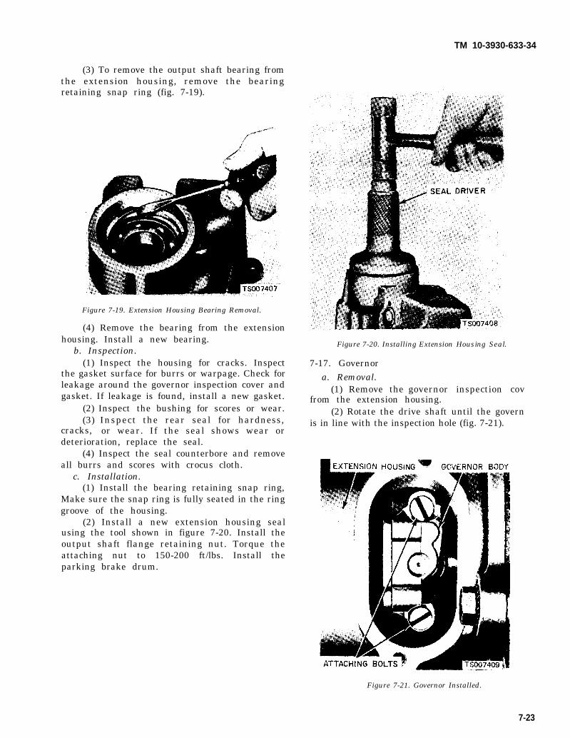
(3) To remove the output shaft bearing fromthe extension housing, remove the bearingretaining snap ring (fig. 7-19).
Figure 7-19. Extension Housing Bearing Removal.
(4) Remove the bearing from the extensionhousing. Install a new bearing.
b. Inspection.(1) Inspect the housing for cracks. Inspect
the gasket surface for burrs or warpage. Check forleakage around the governor inspection cover andgasket. If leakage is found, install a new gasket.
(2) Inspect the bushing for scores or wear.(3) Inspect the rear seal for hardness,
cracks, or wear. If the seal shows wear ordeterioration, replace the seal.
(4) Inspect the seal counterbore and removeall burrs and scores with crocus cloth.
c. Installation.(1) Install the bearing retaining snap ring,
Make sure the snap ring is fully seated in the ringgroove of the housing.
(2) Install a new extension housing sealusing the tool shown in figure 7-20. Install theoutput shaft flange retaining nut. Torque theattaching nut to 150-200 ft/lbs. Install theparking brake drum.
TM 10-3930-633-34
Figure 7-20. Installing Extension Housing Seal.
7-17. Governora. Removal.
(1) Remove the governor inspection covfrom the extension housing.
(2) Rotate the drive shaft until the governis in line with the inspection hole (fig. 7-21).
Figure 7-21. Governor Installed.
7-23

TM 10-3930-633-34
(3) Remove the governor valve body fromthe counterweight. Do not drop the attachingbolts or the valve parts into the extensionhousing.
b. Disassembly.(1) Remove the governor valve body cover.(2) Remove the valve body from the
counterweight.(3) Remove the plug, sleeve, and the valve
and spring from the body (fig. 7-22).
Figure 7-22. Governor Parts.(4) Remove the screen from its bore in the
valve body.c. Inspection.
(1) Inspect the governor valves and bores forscores. Minor scores may be removed from thevalves with crocus cloth. Replace the governor ifthe valves or body is deeply scored.
(2) Inspect the governor screen for ob-structions. The screen must be clean and free offoreign material. If it is contaminated, it shouldbe cleaned in a suitable solvent and thoroughlyblown out with compressed air.
(3) Check for free movement of the valves inthe bores. The valves should slide freely of theirown weight in the bores when dry. Inspect fluidpassages in the valve body and counterweight forobstructions. All fluid passages must be clean.
(4) Check the mating surface of governorvalve and the counterweight for burrs or scratch-es.
d. Assembly.(1) Install the governor valve and spring
assembly in the bore of the valve body. Install thesleeve, and plug.
(2) Install the screen.(3) Install the body on the counterweight.
Make sure the fluid passage in the body and thecounterweight are aligned.
(4) Position the valve body cover on thebody, and install the screws.
e. Installation.(1) Lubricate the new governor valve parts
with transmission fluid. The valve must movefreely in the valve body bore.
(2) Install the governor body on thecounterweight. so that the valve body cover isfacing rearward. Tighten the two attaching boltssecurely.
(3) Install the governor inspection cover,using a new gasket.
7-18. Pressure Regulatora. Removal.
(1) Drain the fluid from the transmission,and remove the pan and fluid screen.
(2) Remove the small compensator pressuretube from the control valve body and the pressureregulator (fig. 7-14).
(3) Remove the main pressure oil tube first,by gently prying up the end that connects to themain control valve assembly. Then, remove theother end of the tube from the pressure regulator.Be sure to remove the tube in this manner.Failure to do so could kink or bend the tube,causing excessive transmission internal leakage.
(4) Remove the pressure regulator springretainer, springs and spacer. Maintain pressureon the retainer to prevent the springs from flyingout.
(5) Remove the pressure regulator attachingbolts and washers, and remove the regulator.
b. Disassembly and Inspection.(1) Remove the valves from the regulator
body.(2) Remove the regulator body cover at-
taching screws and remove the cover (fig. 7-23).
Figure 7-23. Pressure Regulator Parts.
7-24
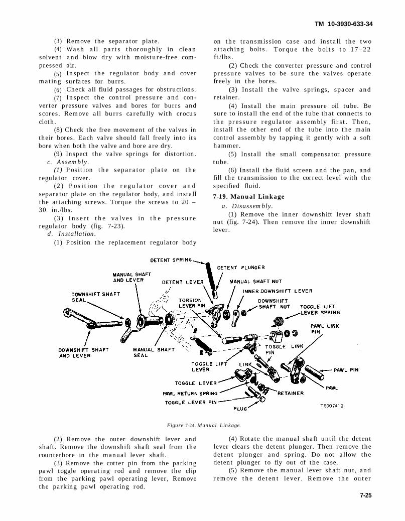
(3)(4)
solventpressed
(5)mating
(6)(7)
Remove the separator plate.Wash all parts thoroughly in cleanand blow dry with moisture-free com-air.Inspect the regulator body and coversurfaces for burrs.Check all fluid passages for obstructions.Inspect the control pressure and con-
verter pressure valves and bores for burrs andscores. Remove all burrs carefully with crocuscloth.
(8) Check the free movement of the valves intheir bores. Each valve should fall freely into itsbore when both the valve and bore are dry.
(9) Inspect the valve springs for distortion.c. Assembly.
(1) Position the separator plate on theregulator cover.
(2) Position the regulator cover andseparator plate on the regulator body, and installthe attaching screws. Torque the screws to 20 –30 in./lbs.
(3) Insert the valves in the pressureregulator body (fig. 7-23).
d. Installation.(1) Position the replacement regulator body
TM 10-3930-633-34
on the transmission case and install the twoattaching bolts. Torque the bolts to 17–22ft/lbs.
(2) Check the converter pressure and controlpressure valves to be sure the valves operatefreely in the bores.
(3) Install the valve springs, spacer andretainer.
(4) Install the main pressure oil tube. Besure to install the end of the tube that connects tothe pressure regulator assembly first. Then,install the other end of the tube into the maincontrol assembly by tapping it gently with a softhammer.
(5) Install the small compensator pressuretube.
(6) Install the fluid screen and the pan, andfill the transmission to the correct level with thespecified fluid.
7-19. Manual Linkagea. Disassembly.
(1) Remove the inner downshift lever shaftnut (fig. 7-24). Then remove the inner downshiftlever.
Figure 7-24. Manual Linkage.
(2) Remove the outer downshift lever and (4) Rotate the manual shaft until the detentshaft. Remove the downshift shaft seal from the lever clears the detent plunger. Then remove thecounterbore in the manual lever shaft. detent plunger and spring. Do not allow the
(3) Remove the cotter pin from the parking detent plunger to fly out of the case.pawl toggle operating rod and remove the clip (5) Remove the manual lever shaft nut, andfrom the parking pawl operating lever, Remove remove the detent lever. Remove the outerthe parking pawl operating rod.
7-25

TM 10-3930-633-34
manual lever and shaft from the transmissioncase.
(6) Tap the toggle lever sharply toward therear of the case to remove the plug and pin.
(7) Remove the pawl pin by working thepawl back and forth. Remove the pawl and togglelever assembly, and then disassemble.
(8) Remove the manual shaft seal and casevent tube.
b. Assembly.(1) Coat the outer diameter of a new manual
shaft seal with sealer, then install the seal in thecase with a driver.
(2) Install the vent tube in the transmissioncase.
(3) Assemble the link to the pawl with thepawl link pin, washer, and pawl return spring.Assemble the toggle lever to the link with thetoggle link pin. Position the pawl return springover the toggle link pin, and secure it in placewith the washer and the small retainer clip. In-stall the assembly in the transmission case byinstalling the pawl pin and the toggle lever pin.Install the torsion lever assembly. Position thespring on the torsion lever with a screwdriver.Make certain that the short side of toggle doesnot extend beyond the largest diameter of the ballor the toggle lever pin. Tap the toggle lever in orour as necessary to center the toggle lever on theball.
(4) Install the manual lever and shaft in thetransmission case. Position the detent lever onthe shaft, and secure it with a nut. Tighten thenut to 20— 30 ft/lbs torque. Rotate the manuallever to the rear of the case. Position the detentspring in the case. Hold the detent plug on thespring with a 3/16 inch socket wrench, thendepress the spring until the plug is flush with thecase. Carefully rotate the manual lever to thefront of the case to secure the plug. A piece of thinwalled tubing may be used to depress the plug if asmall socket wrench is not available.
(5) Position the ends of the parking pawloperating rod in the detent lever and toggle liftlever, and secure with the two small retainingpins,
(6) Install a new seal on the downshift levershaft, then install the lever and shaft in the case.Position the inner downshift lever on the innerend of the shaft with the mark 0 facing toward thecenter of the case. Install the lockwasher and nut,then tighten the nut to 17– 20 ft/lbs torque.
(7) Check the operation of the linkage. Thelinkage should operate freely without binding.
7-20. Front Pumpa. Disassembly.
(1) Remove the stator support attachingscrews and remove the stator support. Mark thetop surface of the pump driven gear with Prussianblue to assure correct assembly. Do not scratchthe pump gears.
(2) Remove the drive and driven gears fromthe pump body.
(3) Refer to figure 7-25 for a disassembledview of the front pump. Inspect the pump bodyhousing, gear pockets and crescent for scores.
Figure 7-25. Front Pump.
(4) If the front pump housing bushingrequires replacement, refer the unit to depotmaintenance.
(5) If any parts other than the stator sup-port, bushings or oil seal are found defective,replace the pump as a unit. Minor burrs andscores may be removed with crocus cloth. Thestator support is serviced separately.
(6) Bolt the front pump to the transmissioncase with capscrews.
(7) If the oil seal requires replacement,install the oil seal remover shown in figure 7-26.Then pull the front seal from the pump body.
Figure 7-26. Removing Front Pump Seal.
(8) Clean the pump body counterbore. Theninspect the bore for rough spots. Smooth up thecounterbore with crocus cloth.
7-26

TM 10-3930-633-34
(9) Remove the pump body from thetransmission case.
b. Inspection.(1) Inspect the mating surfaces of the pump
body and cover for burrs.(2) Inspect the drive and driven gear bearing
surface for scores, and check the gear teeth forburrs.
(3) Check the fluid passages for ob-struct ions.
(4) If any parts are found defective, replacethe pump as a unit. Minor burrs and scores maybe removed with crocus cloth.
c. Assembly and Installation.(1) Install new oil seal into front pump
cover, using a seal driver as shown in figure 7-27.
Figure 7-27. Installing Front Pump Seal.
(2) Place the pump driven gear in the pumpbody with the mark on the gear facing down.Install the drive gear in the pump body with thechamfered side of the flats facing down.
(3) Install the stator support and attachingscrews. Check, the pump gears for free rotation.
7-21. Rear Pump
a. Disassembly.(1) Remove the screws and lockwashers
which secure the pump cover to the pump body,and remove the cover.
(2) Remove the drive gear from the pumpbody.
b. Inspection.(1) Remove the drive gear from the pump
body.(2) Inspect the gear pocket of the pump body
(3) Inspect the inner bushing and the drivegear bearing surface for scores.
(4) Check all fluid passages for obstructions,and check mating surfaces and gasket surfaces ofthe pump body and cover for burrs.
(5) Inspect the pump cover bearing surfacefor scores. Minor burrs or scores may be removedwith crocus cloth.
c. Assembly.(1) Install the drive gear in the pump body.(2) Install the pump cover, attaching screws
and lockwashers. Torque the screws to 25 — 35in./lbs.
7-22. Rear Clutcha. Disassembly.
(1) Remove the clutch pressure plate snap.ring, and remove the pressure plate from thedrum. Remove the waved cushion spring.Remove the composition and steel plates.
(2) Compress the spring with the toolsshown in figure 7-28 and remove the snap ring.
Figure 7-28. Removing Snap Ring.
(3) Guide the spring retainer while releasingthe pressure to prevent the retainer from lockingin the snap ring grooves.
(4) Position the primary sun gear shaft inthe rear clutch, Place an air hose nozzle in one ofthe holes in the shaft, and place one finger overthe other hole. Then force the clutch piston out ofthe clutch drum with air pressure. Hold one handover the piston to prevent damage to the piston.
(5) Remove the inner and outer seal ringsfrom the clutch piston.
(6) If the rear clutch sun gear is worn ordamaged, replace the gear and drum assembly.
b. Inspection.(1) Inspect the drum band surface, the
bushing, and thrust surfaces for scores. Minorscores may be removed with crocus cloth. Badlyscored parts must be replaced. Inspect the clutchpiston bore and the piston inner and outer bearingsurfaces for scores. Check the air bleed ball valve
for scores or pitting.
7-27

TM 10-3930-633-34
in the clutch piston for free movement. Check theorifice to make sure it is not plugged.
(2) Check the fluid passages for ob-structions. All fluid passages must be clean andfree of obstructions.
(3) Inspect the clutch plates for wear andscoring and check the plates for fit on the clutchhub serrations. Replace all plates that are badlyscored, worn or do not fit freely in the hubserratio ns.
(4) Inspect the clutch pressure plate forscores on the clutch plate bearing surface. Checkthe clutch release spring(s) for distortion.
(5) Inspect the needle bearing for wornrollers.
c. Assembly.(1) Install new inner and outer seal rings on
the piston.(2) Lubricate seals and install piston into
cylinder, being careful not to damage seal rings.(3) Install the clutch release spring, and
position the retainer on the spring.(4) Install the tool on the spring retainer as
shown in figure 7-28. Compress the clutch spring,and install the snap ring. While compressing thespring, guide the retainer to avoid interference ofthe retainer with the snap ring groove. Make surethe snap ring is fully seated in the groove. Whennew composition clutch plates are used, soak theplates in automatic transmission fluid for 15minutes before they are assembled.
(5) Install the external tabbed wavedcushion spring. Then, install the composition andthe steel clutch plates alternately, starting with asteel plate.
(6) Install the clutch pressure plate with thebearing surface down. Then install the clutchpressure plate snap ring. Make sure the snap ringis fully seated in the groove.
(7) Check the free pack clearance betweenthe pressure plate and the first internal plate witha feeler gage. The clearance should be 0.030-0.055inch. If the clearance is not within specifications,selective snap rings are available in the followingthicknesses: 0.060-0.064, 0.074-0.078, 0.088-0.092 and 0.102-0.106 inch. Insert the correct sizesnap ring and recheck the clearance.
(8) Install the thrust washer on the primarysun gear shaft. Be sure the thrust washer is in-stalled with the tabs of the washer away from thesun gear thrust face. Lubricate all parts withautomatic transmission fluid or petroleum jelly.Install the two center seal rings.
(9) Install the rear clutch on the primary sungear shaft. Be sure all of the needles are in the hub
if the unit is equipped with loose needle bearings.Assemble two seal rings in the front grooves.
(10) Install the steel and the bronze thrustwashers on the front of the secondary sun gearassembly. If the steel washer is chamfered, placethe chamfered side down.
7-23. Front Clutcha. Disassembly.
(1) Remove the clutch cover snap rings witha screwdriver, and remove the input shaft fromthe clutch drum.
(2) Remove the thrust washer from thethrust surface of the clutch hub. Insert one fingerin the clutch hub, and lift the hub straight up toremove the hub from the clutch drum.
(3) Remove the composition and the steelclutch plates, and then remove the pressure platefrom the clutch drum.
(4) Place the front clutch spring compressoron the release spring. Position the clutch drum onthe bed of an arbor press, and compress therelease spring with the arbor press until therelease spring snap ring can be removed (fig. 7-29).
Figure 7-29. Removing Front Clutch Snap Ring.(5) Remove the clutch release spring from
the clutch drum.(6) The piston can be forced out of the
housing with airagainst the clutchhousing, and forceSee figure 7-30.
pressure. Place the nozzleapply hole in the front clutchthe piston out of the housing.
7-28

TM 10-3930-633-34
Figure 7-30. Removing Piston.
(7) Remove the piston inner seal from theclutch housing . Remove the piston outer sealfrom the groove in the piston.
(8) If the input shaft bushing is worn ordamaged, replace the drum.
b. Inspection.(1) Inspect the clutch cylinder thrust sur-
faces, piston bore, and clutch plate serrations forscores or burrs. Minor scores or burrs may beremoved wit h crocus cloth. Replace the clutchcylinder if it is badly -scored or damaged.
(2) Check the fluid passages in the clutchcylinder for obstructions. Clean out all fluidpassages. Inspect the clutch piston for scores andreplace if necessary. Inspect the piston check ballfor freedom of movement and proper seating (fig.7-31).
Figure 7-31. Clutch Piston Check Ball.
(3) Check the clutch release spring fordistortion and cracks. Replace the spring if it isdistorted or cracked.
(4) Inspect the composition and the steelclutch plates and the clutch pressure plate forworn or scored bearing surfaces. Replace all partsthat are deeply scored.
(5) Check the clutch plates for flatness and fiton the clutch hub serrations. Discard any plate
7-29
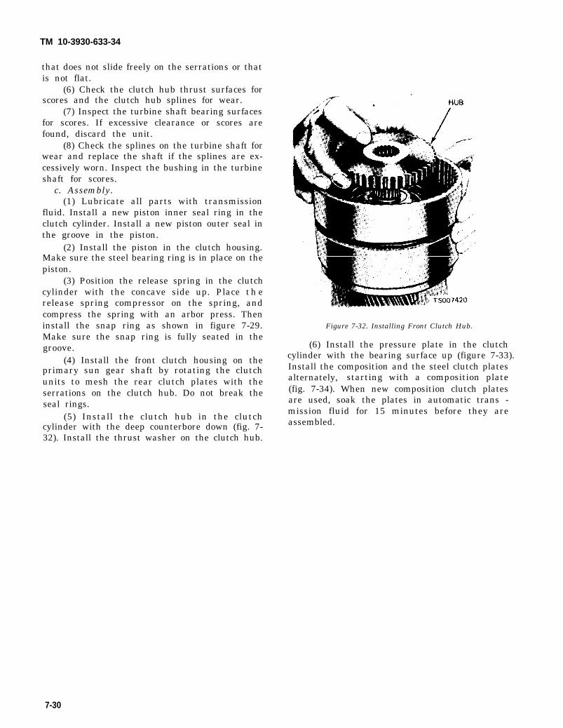
TM 10-3930-633-34
that does not slide freely on the serrations or thatis not flat.
(6) Check the clutch hub thrust surfaces forscores and the clutch hub splines for wear.
(7) Inspect the turbine shaft bearing surfacesfor scores. If excessive clearance or scores arefound, discard the unit.
(8) Check the splines on the turbine shaft forwear and replace the shaft if the splines are ex-cessively worn. Inspect the bushing in the turbineshaft for scores.
c. Assembly.(1) Lubricate all parts with transmission
fluid. Install a new piston inner seal ring in theclutch cylinder. Install a new piston outer seal inthe groove in the piston.
(2) Install the piston in the clutch housing.Make sure the steel bearing ring is in place on thepiston.
(3) Position the release spring in the clutchcylinder with the concave side up. Place therelease spring compressor on the spring, andcompress the spring with an arbor press. Theninstall the snap ring as shown in figure 7-29.Make sure the snap ring is fully seated in thegroove.
(4) Install the front clutch housing on theprimary sun gear shaft by rotating the clutchunits to mesh the rear clutch plates with theserrations on the clutch hub. Do not break theseal rings.
(5) Install the clutch hub in the clutchcylinder with the deep counterbore down (fig. 7-32). Install the thrust washer on the clutch hub.
Figure 7-32. Installing Front Clutch Hub.
(6) Install the pressure plate in the clutchcylinder with the bearing surface up (figure 7-33). Install the composition and the steel clutch platesalternately, starting with a composition plate(fig. 7-34). When new composition clutch platesare used, soak the plates in automatic trans -mission fluid for 15 minutes before they areassembled.
7-30

Figure 7-33.
TM 10-3930-633-34
(7) The final friction plate to be installed isselective. Install the thickest plate that will be aminimum of 0.010 inch below input shaft shoulderin cylinder. For all other plates, use the thinnestavailable. Refer to TM 10-3930-633-34P foravailable plate thicknesses.
(8) Install the turbine shaft in the clutchcylinder, and then install the snap ring. Makesure the snap ring is fully seated in the groove.
(9) Install the thrust washer on the turbineshaft.
7-24. Component InspectionPrior to reassembly of the transmission, check
for damage to the case and other parts as outlinedbelow:
a. Case.(1) Inspect the case for cracks and stripped
threads. Inspect the gasket surfaces and matingsurfaces for burrs. Check the vent for ob-structions, and check all fluid passages for ob-structions and leakage.
(2) Inspect the case bushing for scores.Check all parking linkage parts for wear ordamage.
(3) Use helicoil inserts to repair damagedthreads.
b. Primary Sun Gear Shaft.(1) Inspect the primary sun gear for broken
or worn teeth. Inspect all thrust surfaces andjournals for scores. Check all fluid passages forobstructions and leakage. Inspect the seal ringgrooves for burrs. Refer to figure 7-35.
Figure 7-34. Installing Clutch Plates.
7-31

TM 10-3930-633-34
Figure 7-35. Primary Sun Gear Shaft.
(2) Inspect the sun gear shaft splines forburrs and wear.
(3) Check the fit of the seal rings in thegrooves of the shaft, The rings should enter thegrooves freely without bind.
(4) Check the fit of the seal rings in theirrespective bores. A clearance of 0.002-0.009 inchshould exist between the ends of the rings.
(5) Install the seal rings on the shaft andcheck for free movement in the grooves.
c. One-way Clutch.(1) Inspect the outer and inner races for
scores or damaged surface area where the rollerscontact the races. If the outer race is damaged onthe low reverse clutch hub, it must be replaced.
(2) Inspect the rollers and springs for ex-cessive wear or damage.
(3) Inspect the spring and roller case for bentor damaged spring retainers.
d. Output Shaft.(1) Inspect the thrust surfaces and journals
for scores, Inspect the internal gear for broken orworn teeth.
(2) Inspect the ring grooves for burrs.(3) Inspect the keyway and drive ball pocket
for wear, and inspect the splines for burrs, twistor wear.
(4) Inspect the external parking gear teethfor damage and the speedometer drive gear teethfor burrs.
(5) If either the output shaft or ring gear hasbeen replaced, place the assembled unit with thegear face down on the bench, push the shaftdownward, and check the clearance between thetop of the snap ring and its groove. If thisclearance exceeds 0.002 inch, replace the snapring wit h a thicker ring to reduce the clearance toless than 0.002 inch. Selective snap rings areavailable in several thicknesses for this purpose.
e. Distributor Sleeve.(1) Inspect the distributor sleeve for scores or
excessive ring wear. Inspect the distributor sleevepassages for obstructions.
(2) Check the fit of the fluid tubes in thedistributors.
f. Planet Carrier and Center Support.(1) Inspect the clutch outer race, inner race,
band surface, pinion gears, bearings and thrustwasher (fig. 7-12) for-roughness. -
(2) Inspect the center supportroughness.
bushing for
7-32

TM 10-3930-633-34
CHAPTER 8
REPAIR OF PROPELLER SHAFT
8-1. GeneralThe propeller shaft transmits the power from
the output shaft of the transmission to the inputshaft of the rear axle reduction gearcase. Designfeatures of the shaft permit changes in shaftlength and relative angles between axle andtransmission while under load.8-2. Removal and Installation
a. Removal. Removal of the propeller shaftfrom the vehicle is best accomplished with theflange yokes intact. Proceed as follows:
(1) Set the parking brake firmly and block allwheels of the vehicle, Have the vehicle on a levelsurface.
(2) Remove the capscrews, nuts and lock-washers securing the flange yoke to the parkingbrake drum on the transmission output shaft.
(3) Remove the capscrews, nuts and lock-washers securing the flange yoke to the inputflange on the rear axle reduction gearcase.
(4) Collapse the shaft slightly, which willallow removal of the shaft assembly from betweenthe transmission and axle.
b. Installation.(1) Collapse the shaft slightly to allow fitting
up between the parking brake drum and axleinput shaft.
(2) Align the parking brake flange yoke (slipyoke end) with the mounting holes, and install thecapscrews, nuts and lockwashers to secure theflange yoke. Tighten hardware to 40-44 ft/lbs.
(3) Align the flange yoke (stub shaft end)with the companion flange on the rear axlereduction gearcase. Install the capscrews, nutsand lockwashers. Tighten hardware to 40—44ft/lbs.8-3. Propeller Shaft Repair
Propeller shaft repairs generally consist ofcomplete disassembly and cleaning, inspection,and reassembly with the use of new parts whereindicated. -
a. Disassembly.identification, and
Refer to figure 8-1 for partsproceed as follows:
8-1

TM 10-3930-633-34
1. Screw 6. Flange yoke 11. Sleeve yoke2. Lockwasher 7. Lubrication fitting 12. Stub yoke3. Nut 8. Dust cap 13. Screw4. Shaft assembly 9. Steel washer 14. Lockwasher5. Cross and bearings 10. Cork washer 15. Nut
Figure 8-1. Propeller Shaft Assembly.
(1) Remove snap rings by pinching the endstogether with a pair of needle nose pliers. If a ringdoes not readily free from the groove, tap the endof the bearing cap lightly to relieve the pressureagainst the ring.
(2) Remove needle bearings (5) by driving onthe end of one bearing cap until the oppositebearing cap is forced out of the yoke. Turn thejoint over and tap on the end of the journal crossuntil the opposite bearing cap is free. Use awooden dowel, of a diameter about 1/32 to 1/16smaller than the hole in the yoke, as a drift.
(3) Separate journal cross and yokes bysliding journal to the side of the yoke, and tiltingover the top of the yoke lug.
(4) Free slip yoke (11) and stub yoke (12) byunscrewing dust cap (8) and pulling apart.
b. Cleaning, Inspection, and Repair.(1) Clean all parts in a bath of solvent,
Federal Specification P-D-680. Allow the parts toremain in the solvent for some time to loosen upany particles of grease or foreign matter, Removeany burrs or rough spots from any machinedsurf aces.
8-2
(2) Do not disassemble the needle bearings.Clean with short stiff brush and blow out withcompressed air. Work a small quantity oflubricant (140 S. A. E. oil) into each bearing capand turn the needle bearing on the trunnion tocheck wear. Replace if worn.
(3) Because worn needle bearings used with ajournal cross or new needle bearings used with aworn journal cross will wear more rapidly, makinganother replacement necessary in a short time,always replace the journal cross and four needlebearing caps as a unit. These parts are furnishedtogether in the service assembly. (See TM 10-3930-633-34P).
c. Assembly. Refer to figure 8-1 and assemblethe propeller shaft as follows:
(1) Lubricate the splines on the stub shaftwith clean engine oil (OE) and place dust cap (8),steel washer (9) and cork washer (10) over thestub spline (11).
(2) Slide stub yoke (12) into slip yoke (11),being very careful to make certain the arrowsstamped on the slip yoke and stub yoke areexactly in line. Tighten dust cap on slip yoke.

TM 10-3930-633-34
CAUTIONFailure to align arrows will cause ex-cessive shaft vibration and rapid failure.(3) Work the bearing journal into place in
each yoke, and install bearings (5) through theeyes of each yoke.
(4) Install snap rings to secure bearings inyoke.
(5) Lubricate the shaft assembly by applyingproper lubricant (LO 10-3930-633-12) with agrease gun to the fittings on each bearing journaland on the slip yoke. Grease should be added untilit begins to extrude through the bearing and slipyoke seals.
(6) Check the assembly before installation forthe following conditions:
(a) No damage or dents on propeller shafttubing which could cause unbalance. If the dentsare severe enough they can weaken the tube and afailure might occur under torque load.
(b) Splines should slide freely with slightdrag from spline seal.
(c) Bearings should flex and be free fromexcessive bind. A slight drag is the most desirablecondition on a new universal joint. This drag isfrom the bearing seals. When rotating, yoke lugdeflections cause some additional clearance.Excessive looseness is not desirable due to theresulting unbalance.
(d) Mounting flanges and pilots should befree from burrs and paint which would not allowproper seating at assembly.
8-3

TM 10-3930-633-34
CHAPTER 9
REPAIR OF WHEELS AND BRAKES
Section I. WHEELS AND TIRES
9-1. GeneralThe rear wheels of the tractor are a one-piece
welded steel disc-type wheel with split lock rings,sized for 6:50x16 inch tires. Normal inflationpressure is 45 lbs. The front wheels are two-piecesplit type, sized for 6:50x10 inch tires. Normalinflation pressure is 100 lbs. Both front and reartires are 6 ply, tube type.
9-2. Replacing Tires and Tubes
Always deflate tires completely beforeattempting remounting. Remove valvecore to insure complete bleed-off of anyresidual pressure.
a. Remounting Rear Tires.(1) Jack up vehicle so that tire is clear of the
floor.(2) Deflate tire completely, and remove valve
core.(3) Remove wheel mounting nuts and lift
wheel and tire off vehicle.(4) Lay wheel on the floor with the lock ring
side facing up.(5) Using the curved end of one rim tool, and
the hooked end of another, pry the tire beaddownward, away from lock ring, using downwardpressure on rim tools.
(6) Continue prying operation completelyaround the tire until the bead is completely un-seated from the lock ring.
(7) To disengage lock ring from the gutter,
insert one rim tool in the tool slot of the lock ring,and pry ring upward and outward.
(8) Continue in this manner progressivelyaround rim until ring is completely removed.Then remove tire and tube from wheel.
b. Mounting Rear Tires.(1) Place tube inside tire, and lay tire over
wheel (lock ring side up) so that tire valve stem isin line with the hole in the wheel.
(2) Pull the valve stem through the hole inthe wheel.
(3) Lay lock ring over the wheel and step onthe ring at the split, to force one end down into itsseat.
(4) Continue around the lock ring using footpressure to force the ring into place. Make ab-solutely certain the ring is properly seated all theway around.
(5) Inflate tire to about 10 PSI, then deflateand inflate again to 45 PSI. Use a safety cagewhen inflating tire if one is available. Otherwise,lay tire on floor with lock ring side down, or in-flate with lock ring side away from operator.
(6) Mount wheel and tire assembly onvehicle, and torque wheel nuts to 125 — 140 ft/lbs.
c. Remounting Front Tires.(1) Raise or jack up vehicle until the tire
clears the floor. Deflate tire completely andremove valve core.
(2). Refer to figure 9-1 and remove the nuts onthe INNER BOLT CIRCLE ONLY.
9-1

TM 10-3930-633-34
Figure 9-1. Wheel Removal.
(3) Lift the wheel and tire assembly off thevehicle.
(4) Remove the ten capscrews, nuts andwashers securing the wheel halves, and separatethe wheel halves, tire, tube and flap.
d. Mounting Front Tires.(1) Position tube inside tire, lay tire over
inside wheel half.(2) Position outside wheel half so that tire
valve may be pulled through hole in wheel. Makecertain that tube flap is in place.
(3) Insert the ten capscrews from insidewheel half so they protrude through the outsidewheel half. Install nuts and lockwashers over allten screws. Torque screws to 60–75 ft/lbs.
(4) Inflate the tire to 100 PSI in a safetycage. Mount wheel on front axle. Torque wheelnuts to 125—140 ft/lbs.
9-3. Tire Repaira. Once removed, inspect
cuts, bruises, punctures, and
9-5. GeneralThe four wheel hydraulic
internal expanding shoe type.
tires carefully forimbedded objects.
Clean out all rocks and foreign objects lodged inthe tread. Punctures in the tire can be plugged, orrepaired by hot or cold patch methods. Tubes arerepaired by hot or cold patch methods, followingthe instructions furnished with the patchmaterial.
b. Check tire wear pattern carefully for anyuneven wear patterns. Type of uneven wear andtheir causes are: wear in center of tread (over-inflation), wear on both edges of tread (underinflation), wear on one side or “feathering” oftread (out of alignment), and “cupping” or flatspotting (out of balance).
9-4. Wheel RepairCheck wheels carefully for bent condition in rim
or flange area. Straighten as required. Keepwheels clean, especially at the wheel to drummounting flange, and bead seating area. Wheelsevidencing cracks between mounting holes, orany where in the rim area, must be replaced.
Section Il. BRAKE SYSTEM
brakes are of theThe brake system
incorporates a tandem master cylinder where the. front axle brakes and the rear axle brakes are on
separate hydraulic circuits. This arrangementprevents complete loss of braking action in casesof failure at some point in the system. Theoperator’s pedal effort is assisted by a vacuumbooster on the master cylinder pushrod. Engine
vacuum is used to operate the booster. Eachbrake assembly provides a means for mechanicaladjustment of lining-to-drum clearance.
9-2
9-6. Brake Assembly RepairsRepairs to the brake assemblies consist of
reconditioning the brake drums by turning on alathe to true-up the lining contact surface, andthe replacement of worn or defective partsthrough the installation of repair kit parts andshoe and lining sets. Refer to TM 10-3930-633-12for procedures concerning brake adjustment andremoval of wheels and brake drums.
a. Disassembly ( Front Brakes ), Refer to figure9-2 for parts identification and proceed as follows:

TM 10-3930-633-34
1. Screw 7. Return spring 13. Screw2. Lockwasher 8. Clip 14. Lockwasher3. Hex nut 9. Shoe and lining 15. Wheel cylinder RH4. Brake assembly RH 10. Lining 16. Wheel cylinder LH5. Brake assembly LH 11. Rivets 17. Repair kit6. Return spring 12. Bleeder screw 18. Backing plate
Figure 9-2. Front Brake Assembly.
(1) After removal of brake drum, unhook (4) Backing plate (18) is not removed fromreturn springs (6) and (7). axle unless damaged.
(2) Remove shoe and lining assemblies (9) b. Disassembly (Rear Brakes ). Refer to figureand clips (8). 9-3 for parts identification and proceed as follows:
(3) Remove screws (13) and lockwashers (14)and lift off wheel cylinder assembly (15). Removebleeder screw (12).
9-3

TM 10-3930-633-34
1. Return spring 5. Lockwasher 9. Wheel cylinder assembly 13. Bleeder screw2. Shoe and lining 6. Hex nut 10. Pushrod 14. Cylinder kit3. Anchor pin 7. Cotter pin 11. Capscrew 15. Capscrew4. Ring 8. Washer 12. Lockwasher 16. Hex nut
Figure 9-3. Rear Brake Assembly.
(1) Unhook return spring (1). Pull off clip (7)and washer (8) from guide pin.
(2) Pull off ring (4) from each anchor pin (3),and remove the shoe and lining assemblies (2).
(3) Remove cylinder pushrods (10). Removecapscrews (11) and lockwashers (12), and lift offwheel cylinder assembly (9). Remove bleederscrew (13).
(4) Remove nut (6) and lockwasher (5) toremove anchor pin (3),
(5) Backing plate is not to be removedaxle unless damaged.
c. Cleaning, Inspection, and Repair.(1) Clean cylinder castings thoroughly
solvent, Federal Specification P-D-680.
9-4
from
with
(2) After cleaning, hold the cylinder castingup to a strong light and sight through thecylinder bore. Any blemishes such as pitting,visible wear patterns, etc., will necessitate unitreplacement.
(3) A hone may be used to “clean-up” thecylinder, provided its use does not materiallyincrease the size of the bore.
(4) Cylinder diameter must not exceed thenominal dimension by more than 0.007 inch. Thisfigure can be checked with a “GO-NO GO” typegage or by inserting a piston into the cylinder andchecking clearance with a wire gage.
(5) If mineral oil is present in the system, the

TM 10-3930-633-34
rubber cups will be enlarged and very soft. Thesecannot be used and should be discarded.
(6) Cylinder walls must be smooth and notpitted or scratched and be free from burrs.Remove light pits, scratches and burrs with ahone. If cylinder does not clean up with lighthoning, cylinder must be replaced.
(7) occasionally grease retainers becomeworn, allowing lubricant from wheel bearings toleak through in the brake drum. When greasecomes into contact with end closures, theybecome soft and enlarged, preventing them fromprotecting the cylinder from foreign matter. Ifthis occurs, replace defective parts.
(8) Inspect anchor pins for rust, or scoring.Clean all dirt and rust from anchor pins and coatpins lightly with “Lubriplate 110” or equivalent.
(9) Check return springs, washers andretaining clips for wear or corrosion and replace asrequired.
(10) Check brake shoes for wear and grease oroil soaking. Replace shoes which are worn towithin 1/32 of the rivet heads or shoe surface.
d. Reassembly.(1) Reassemble front brakes in accordance
with figure 9-2.(2) Reassemble rear brakes in accordance
with figure 9-3.(3) Always install wheel cylinder spring,
pie ton and cups, and cylinder boots, and mountthe wheel cylinder to the backing plate beforeinstalling shoe and lining assemblies.
(4) After reassembly of brakes, and in-stallation of brake drums, bleed and adjustbrakes as outlined in TM 10-3930-633-12.
9-7. Brake Drum Refinishing
a. Minor scores on a brake drum can beremoved with fine emery cloth, provided theemery is thoroughly cleaned off the drum after theoperation.
b. A badly scored, rough, or out-of-round drumshould be ground or turned on a drum lathe. Donot remove any more material from the drum thanis necessary to provide a smooth surface for thebrake shoe contact. In no case should the drumsbe turned to more than 0.060 inch oversize.
9-8. Vacuum Power Unit Decryptiona. General. The vacuum power unit (fig. 9-4) is
a self-contained vacuum-hydraulic unit for powerbraking that uses engine manifold vacuum andatmospheric pressure for its power. It permits theuse of a low brake pedal, and provides reducedpedal effort, compared to the conventional (non-power) hydraulic braking system. The dual-system hydraulic section of the Master-Vat issimilar to the manually operated dual-systemmaster cylinder except that the hydraulic pushrodis a part of the power section. The separatehydraulic systems provided by this mastercylinder prevent a hydraulic failure in eithersystem from affecting the other system. If ahydraulic failure does occur, the driver is aware ofit, either immediately when it happens, or on thenext brake application, because of the increasedpedal travel required to get braking action. Inaddition, vehicle deceleration with only the frontor rear brakes functioning will, usually, be lesseffective, requiring either greater pedal effort forthe same stopping distance or greater distance.
9-5

TM 10-3930-633-34
Figure 9-4. Vacuum Power Unit.
b. Construction. The vacuum power unit front and rear diaphragm and plate assembly, aconsists of three basic elements which are: hydraulic pushrod and a vacuum diaphragm and
(1) A vacuum power chamber (fig. 9-5) plate return spring.consists of a front and rear shell, a center plate, a
9-6
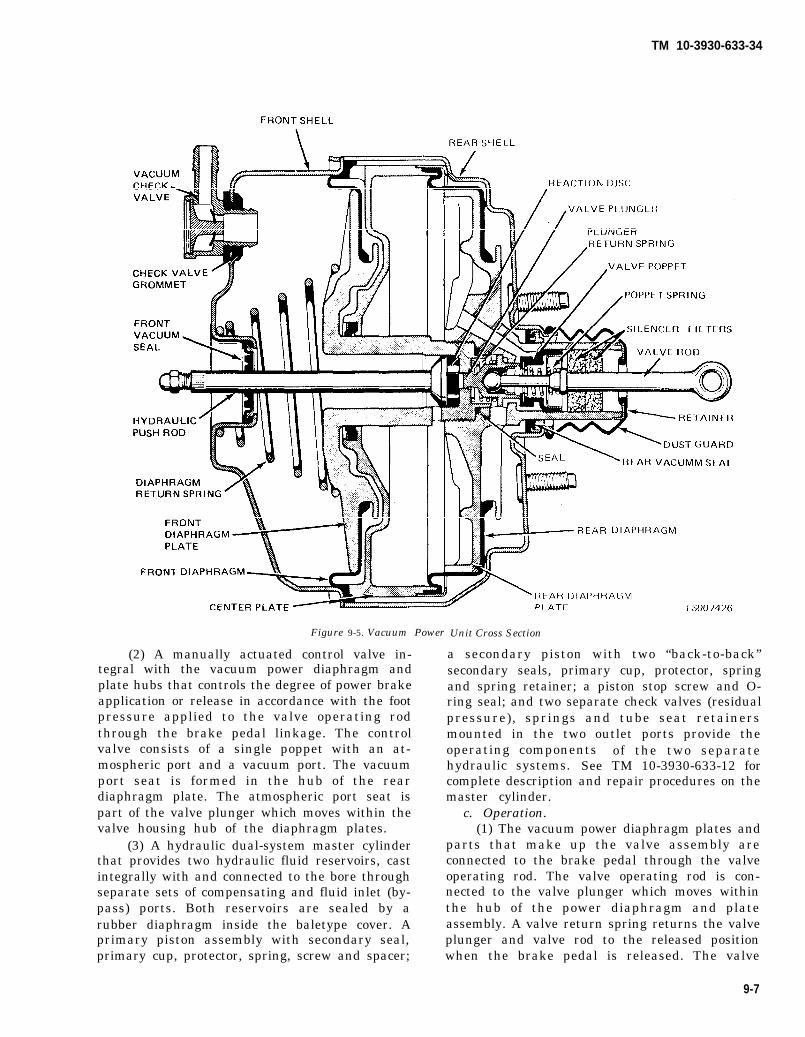
TM 10-3930-633-34
Figure 9-5. Vacuum Power
(2) A manually actuated control valve in-tegral with the vacuum power diaphragm andplate hubs that controls the degree of power brakeapplication or release in accordance with the footpressure applied to the valve operating rodthrough the brake pedal linkage. The controlvalve consists of a single poppet with an at-mospheric port and a vacuum port. The vacuumport seat is formed in the hub of the reardiaphragm plate. The atmospheric port seat ispart of the valve plunger which moves within thevalve housing hub of the diaphragm plates.
(3) A hydraulic dual-system master cylinderthat provides two hydraulic fluid reservoirs, castintegrally with and connected to the bore throughseparate sets of compensating and fluid inlet (by-pass) ports. Both reservoirs are sealed by arubber diaphragm inside the baletype cover. Aprimary piston assembly with secondary seal,primary cup, protector, spring, screw and spacer;
Unit Cross Section
a secondary piston with two “back-to-back”secondary seals, primary cup, protector, springand spring retainer; a piston stop screw and O-ring seal; and two separate check valves (residualpressure), springs and tube seat retainersmounted in the two outlet ports provide theoperating components of the two separatehydraulic systems. See TM 10-3930-633-12 forcomplete description and repair procedures on themaster cylinder.
c. Operation.(1) The vacuum power diaphragm plates and
parts that make up the valve assembly areconnected to the brake pedal through the valveoperating rod. The valve operating rod is con-nected to the valve plunger which moves withinthe hub of the power diaphragm and plateassembly. A valve return spring returns the valveplunger and valve rod to the released positionwhen the brake pedal is released. The valve
9-7

TM 10-3930-633-34
poppet is of the flexible rubber type and issupported by the valve body hub of the reardiaphragm plate.
(2) In the released position, the poppet returnspring holds the poppet against the atmosphericport seat (valve plunger). A special type of seal isused to seal the opening between the valve bodysleeve and the rear shell.
(3) Vacuum is supplied to the power brakeunit through a vacuum check valve mounted inthe front shell. Air for operation is admittedthrough silencer-filters within the valve housing.At its front end, the power section incorporatesanother special seal to close the opening betweenthe front shell and hydraulic pushrod.
(4) The hydraulic pushrod is the link betweenthe vacuum power diaphragm and plate assemblyand the hydraulic pistons in the master cylinder.
The center plate, located between the twodiaphragms, divides the power unit into fourchambers. A long, threaded hub on the front plateslides through the center hole in the center plateand is screwed into the hub of the rear plate tomaintain a set separation between the twodiaphragms as the front and rear plates anddiaphragms move backward and forward. Thisfront plate hub is sealed by a vacuum seal that ispermanently installed in the stationary centerplate. Two drilled air passages intersect in themounting flange of the master cylinder to provide“free breathing” for this cavity during braking.
9-9. Vacuum Power Unit Repair
a. Disassembly. Refer to figure 9-6identification and proceed as follows:
for parts
Figure 9-6. Vacuum Power Unit Exploded View.
(1) Scribe across the flanges of both shells nuts and lockwashers and set master cylinderand the master cylinder to provide a guide mark aside.for assembly. Remove master cylinder attaching
9-8
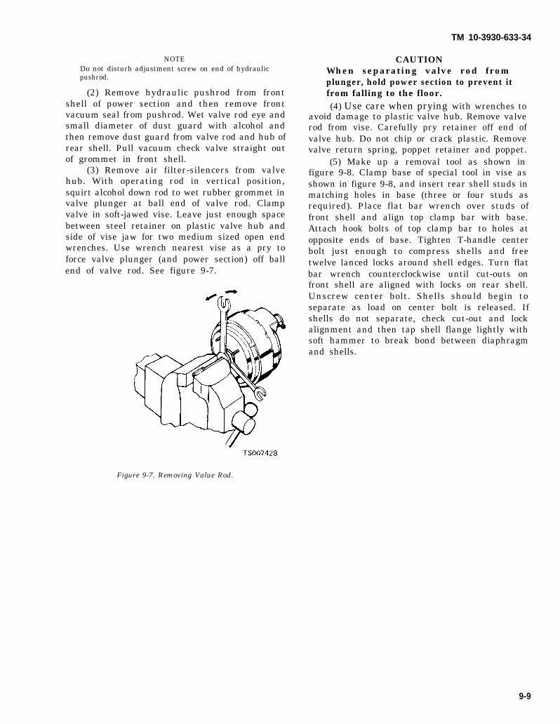
TM 10-3930-633-34
NOTEDo not disturb adjustment screw on end of hydraulicpushrod.
(2) Remove hydraulic pushrod from frontshell of power section and then remove frontvacuum seal from pushrod. Wet valve rod eye andsmall diameter of dust guard with alcohol andthen remove dust guard from valve rod and hub ofrear shell. Pull vacuum check valve straight outof grommet in front shell.
(3) Remove air filter-silencers from valvehub. With operating rod in vertical position,squirt alcohol down rod to wet rubber grommet invalve plunger at ball end of valve rod. Clampvalve in soft-jawed vise. Leave just enough spacebetween steel retainer on plastic valve hub andside of vise jaw for two medium sized open endwrenches. Use wrench nearest vise as a pry toforce valve plunger (and power section) off ballend of valve rod. See figure 9-7.
CAUTIONWhen separating valve rod fromplunger, hold power section to prevent itfrom falling to the floor.(4) Use care when prying with wrenches to
avoid damage to plastic valve hub. Remove valverod from vise. Carefully pry retainer off end ofvalve hub. Do not chip or crack plastic. Removevalve return spring, poppet retainer and poppet.
(5) Make up a removal tool as shown infigure 9-8. Clamp base of special tool in vise asshown in figure 9-8, and insert rear shell studs inmatching holes in base (three or four studs asrequired). Place flat bar wrench over studs offront shell and align top clamp bar with base.Attach hook bolts of top clamp bar to holes atopposite ends of base. Tighten T-handle centerbolt just enough to compress shells and freetwelve lanced locks around shell edges. Turn flatbar wrench counterclockwise until cut-outs onfront shell are aligned with locks on rear shell.Unscrew center bolt. Shells should begin toseparate as load on center bolt is released. Ifshells do not separate, check cut-out and lockalignment and then tap shell flange lightly withsoft hammer to break bond between diaphragmand shells.
Figure 9-7. Removing Value Rod.
9-9

TM 10-3930-633-34
Figure 9-8. Separating Front and Rear Shells.
Press down firmly on top clamp barwhile removing hook bolts from base toprevent internal spring force fromcausing shells to fly apart, Remove hookbolts, top clamp bar, flat bar wrench,front shell and return spring. Lift powerdiaphragm and plate assembly from rearshell and remove rear shell from fixturebase.(6) Wet rear diaphragm spring retainer with
alcohol and remove, using fingers only. Removerear diaphragm from rear plate. Set 1-1 /16” hexbar stock 2“ long in a vise, Set diaphragm andplate assembly on hex stock with hex opening infront plate seated on bar. Twist rear platecounterclockwise, using hard pressure only onatmospheric pressure channel or outer edge ofplate.
(7) After plates have been loosened, remove
9-10
assembly from vise and complete disassembly onbench, front end down. Unscrew rear platecompletely and carefully lift it off front plate hub,grasping valve plunger and spring with otherhand and removing them from bore of front platehub. Remove square ring seal from shoulder ofrear plate.
NOTESeal may stick to shoulder of front plate.
(8) Using a small rod or screwdriver throughcenter bore of front plate, push out reaction disc.Loosen front diaphragm from center plate andslide center plate carefully off front plate hub.
CAUTIONDO NOT damage or remove sealassembly from hub of center plate.(9) Remove front diaphragm from front
plate.(10) Place shell on work bench, studs up,
and drive seal out of shell.

TM 10-3930-633-34
NOTEDO NOT remove seal unless a new seal is available.
b. Cleaning.(1) After disassembly, all metal parts should
be cleaned in solvent, Federal Specification P-D-680. Plastic parts and rubber parts should becleaned ONLY by wiping with a cloth moistenedin the same type solvent. Care should be taken toprevent chipping or cracking of plastic parts.Replace all rubber parts, except powerdiaphragms. After parts have been cleaned, useclean (filtered) dry compressed air to blow dirtand solvent out of recesses and internal passages.
c. Inspection. Inspect all parts for damage orexcessive wear. The power diaphragms must befree of kinks, cracks and tears. Replace anydamaged, worn or chipped parts.
d. Assembly.(1) If vacuum seal and bearing was removed
from rear shell, press new seal into shell cavity,plastic side first (fig. 9-9), until flat rubbersurface is about 5/16” below flat inside shellsurface (.305” minimum).
Figure 9-9. Installing Vacuum Seal.
(2) Install front diaphragm on front plate.Apply a light coat of hydraulic brake fluid tooutside surface of front plate hub and liberally tothe seal in the center plate hub. Carefully guidecenter plate and seal assembly, seal side first,onto front plate hub. Apply hydraulic brake fluidlightly to the front and rear bearing surfaces ofthe valve plunger, being careful not to get anylubricant on the rubber grommet inside theplunger. Assemble valve plunger return spring onvalve plunger as shown in figure 9-6, and setspring and plunger in recess of front plate hub,grommet side up. Place vacuum seal firmlyagainst shoulder on outside of front plate hub. Setrear plate, threaded bore down, over valve
plunger and, using hands only, screw rear plateonto front plate hub. To tighten plates, place 1-1/16” hex bar stock in vise and set plateassembly, front plate down, on hex bar. Using airchannel slot or rear plate edges, hand torqueplates to 120 - 180 in./lbs. Remove plateassembly from vise. Install rear diaphragm onrear plate and over lip of center plate. Assemblediaphragm spring retainer over rear diaphragmand lip of center plate. Using fingers only, pressretainer onto center plate until it seats againstshoulder of center plate.
(3) Apply talcum powder to inside wall ofrear shell. Apply hydraulic brake fluid (orequivalent) liberally to bearing seal in rear shell.Apply hydraulic brake fluid (or equivalent)liberally to cutouts around edge of front shell.Clamp fixture base in vise and insert rear shellstuds through matching holes in base. Whenassembling the plate and diaphragm assembly inthe rear shell, the lugs on the center plate must bealigned between the lances on the rear shell.Carefully guide valve housing sleeve throughbearing seal in rear shell keeping center plate anddiaphragms in correct alignment. Work outer rimof front diaphragm into rear shell so that outerrim is under each of the retaining lances on therear shell. Place large diameter end of diaphragmreturn spring over front plate hub and positionfront shell on spring so that scribe marks on frontand rear shells will be aligned when shells aretwist-locked in place. Place bar wrench over studsof front shell and then attach clamp bar with hookbolts to base. Before tightening center bolt, makecertain cut-outs on front shell are aligned withlocks on rear shell. Guide rim of diaphragm intofront shell. Tighten center bolt until edge of frontshell will clear lances on rear shell. Twist frontshell clock wise in relation to the rear shell untilstop is contacted. Remove tools from powercylinder.
(4) Apply hydraulic brake fluid liberally toentire surface of reaction disc and to piston end ofhydraulic pushrod. Place reaction disc on pistonend of pushrod. Apply Bendix Type “O”Lubricant (or equivalent) sparingly on shaft ofpushrod, keeping lubricant away from adjustingscrew end of pushrod.
Lubricant must not be allowed to get onadjusting screw or threads.(5) Insert pushrod with reaction disc stuck
to it into reaction disc hub of front plate. Twistand press on pushrod to make certain disc isseated firmly. Assemble seal, support plate side
9-11
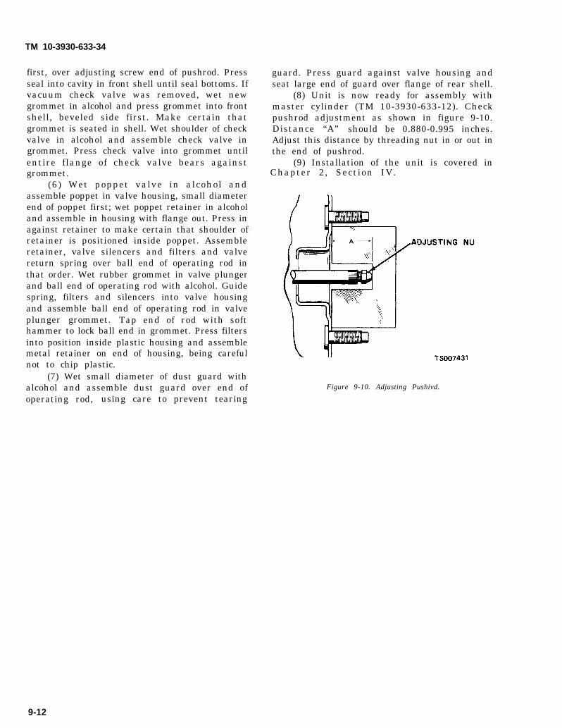
TM 10-3930-633-34
first, over adjusting screw end of pushrod. Pressseal into cavity in front shell until seal bottoms. Ifvacuum check valve was removed, wet newgrommet in alcohol and press grommet into frontshell, beveled side first. Make certain thatgrommet is seated in shell. Wet shoulder of checkvalve in alcohol and assemble check valve ingrommet. Press check valve into grommet untilentire flange of check valve bears against
guard. Press guard against valve housing andseat large end of guard over flange of rear shell.
(8) Unit is now ready for assembly withmaster cylinder (TM 10-3930-633-12). Checkpushrod adjustment as shown in figure 9-10.Distance “A” should be 0.880-0.995 inches.Adjust this distance by threading nut in or out inthe end of pushrod.
(9) Installation of the unit is covered ingrommet.
(6) Wet poppet valve in alcohol andassemble poppet in valve housing, small diameterend of poppet first; wet poppet retainer in alcoholand assemble in housing with flange out. Press inagainst retainer to make certain that shoulder ofretainer is positioned inside poppet. Assembleretainer, valve silencers and filters and valvereturn spring over ball end of operating rod inthat order. Wet rubber grommet in valve plungerand ball end of operating rod with alcohol. Guidespring, filters and silencers into valve housingand assemble ball end of operating rod in valveplunger grommet. Tap end of rod with softhammer to lock ball end in grommet. Press filtersinto position inside plastic housing and assemblemetal retainer on end of housing, being carefulnot to chip plastic.
(7) Wet small diameter of dust guard with
Chapter 2, Section IV.
alcohol and assemble dust guard over end of Figure 9-10. Adjusting Pushivd.
operating rod, using care to prevent tearing
9-12
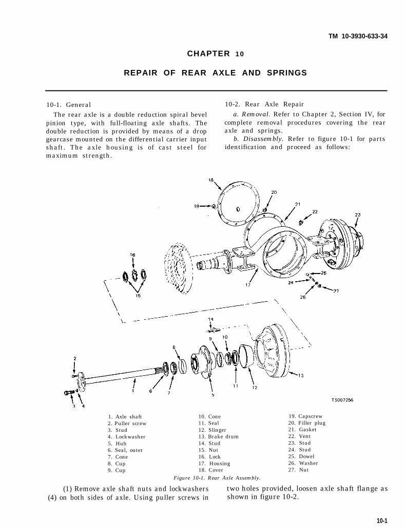
TM 10-3930-633-34
CHAPTER 1 0
REPAIR OF REAR AXLE AND SPRINGS
10-1. General 10-2. Rear Axle Repair
The rear axle is a double reduction spiral bevel a. Removal. Refer to Chapter 2, Section IV, forpinion type, with full-floating axle shafts. The complete removal procedures covering the reardouble reduction is provided by means of a drop axle and springs.gearcase mounted on the differential carrier input b. Disassembly. Refer to figure 10-1 for partsshaft. The axle housing is of cast steel for identification and proceed as follows:maximum strength.
1. Axle shaft2. Puller screw3. Stud4. Lockwasher5. Hub6. Seal, outer7. Cone8. Cup9. Cup
10. Cone11. Seal12. Slinger13. Brake drum14. Stud15. Nut16. Lock17. Housing18. Cover
Figure 10-1. Rear Axle Assembly.
19. Capscrew20. Filler plug21. Gasket22. Vent23. Stud24. Stud25. Dowel26. Washer27. Nut
(1) Remove axle shaft nuts and lockwashers two holes provided, loosen axle shaft flange as(4) on both sides of axle. Using puller screws in shown in figure 10-2.
10-1

TM 10-3930-633-34
Figure 10-2. Loosening Axle Shaft Flange.
(2) Remove axle shaft as shown in figure 10-3.
Figure 10-3. Removing Axle Shaft.
(3) Bend up tang on bearing lock exposedafter removal of axle shaft. Loosen and removebearing nuts and nut lock. Remove bearing cone.Pull off hub and drum assembly. See figure 10-4.
Figure 10-4. Removing Hub and Drum Assembly.
(4) Remove bearing cones, cups, seals andslinger as shown in figure 10-1.
(5) Remove carrier nuts and screws, and liftoff the drop gearcase and differential as anassembly.
c. Cleaning and Inspection.(1) Clean the exterior and interior of the axle
housing with solvent, Federal Specification P-D-680.
(2) Clean each bearing in a container filledwith (clean) solvent, Federal Specification P-D-680. Wash bearings thoroughly. Remove bearingsfrom solvent and strike larger side of cone flatagainst a block of wood to dislodge solidifiedparticles of lubricant. Repeat above operationuntil bearings are thoroughly clean. Bearingsmust be completely free from grease, oil andsolidified particles of lubricant.
(3) After washing bearings, blow them drywith compressed air. Be careful to direct airpressure across bearing to avoid spinning. DONOT SPIN BEARINGS. Bearings may be slowlyrotated by hand to facilitate drying procedure.
(4) Inspect bearings carefully to determine ifthey are in good condition and suitable for furtherservice.
(5) When bearings are clean and dry,lubricate them with new engine oil. Rotate thebearing by hand, and check for wear or roughspots.
(6) Carefully inspect rollers, cages and cupsfor wear, chipping or nicks.
(7) If any defects are found, the bearingsshould be scrapped, and replaced with new onesat reassembly.
(8) All parts of the axle, including gears,axle shaft and hub should be washed thoroughlyin a Stoddard type cleaning solvent.
(9) Examine the gears for cracked, chippedor scored teeth. If any of these conditions exist,the faulty part should be replaced with a newpart.
(10) If magna-flux process is available, useprocess to check parts. Examine teeth of all gearscarefully for wear, pitting, chipping, nicks orscores. If gear teeth show spots where casehardening is worn through, install new gear.Small nicks may be carefully removed with asuitable hone.
(11) Examine axle shafts to make certainthat they are not sprung, bent or splines twistedand that shafts are true.
(12) Seals and gaskets should be replacedwith new ones at reassembly.
d. Reassembly.(1) Using a new gasket, install drop gearcase
and carrier to axle housing. Tighten mountingscrews to 52 - 57 ft/lbs.
10-2
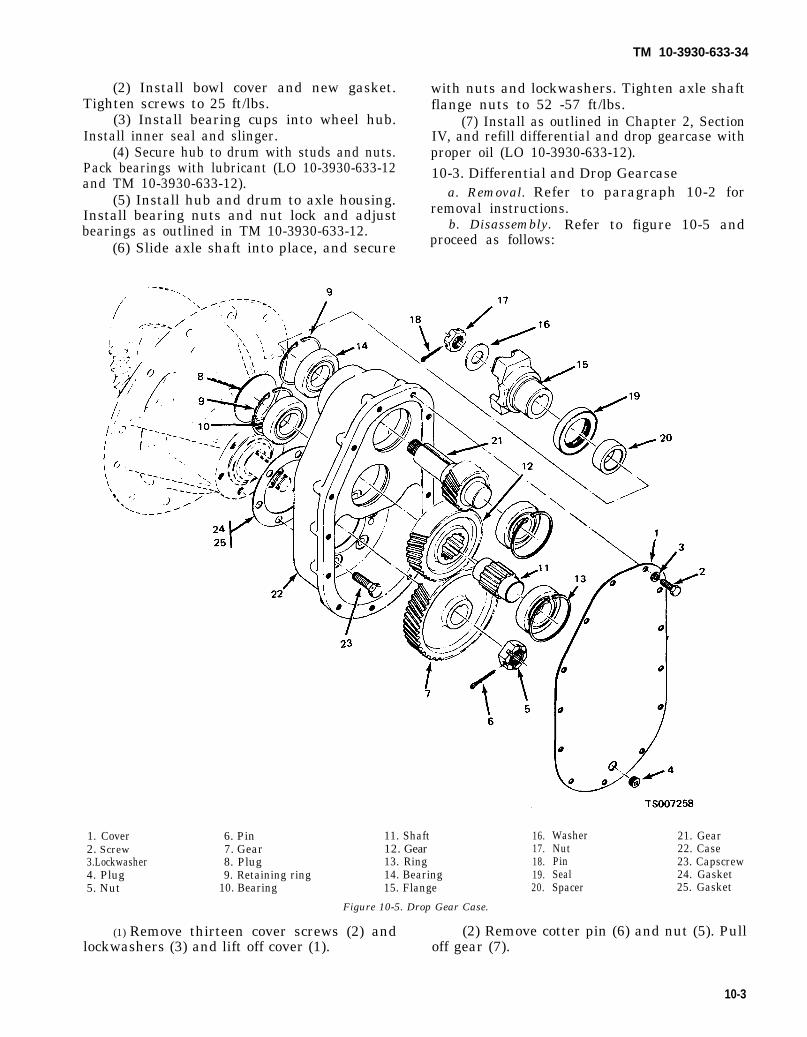
TM 10-3930-633-34
(2) Install bowl cover and new gasket.Tighten screws to 25 ft/lbs.
(3) Install bearing cups into wheel hub.Install inner seal and slinger.
(4) Secure hub to drum with studs and nuts.Pack bearings with lubricant (LO 10-3930-633-12and TM 10-3930-633-12).
(5) Install hub and drum to axle housing.Install bearing nuts and nut lock and adjustbearings as outlined in TM 10-3930-633-12.
(6) Slide axle shaft into place, and secure
with nuts and lockwashers. Tighten axle shaftflange nuts to 52 -57 ft/lbs.
(7) Install as outlined in Chapter 2, SectionIV, and refill differential and drop gearcase withproper oil (LO 10-3930-633-12).10-3. Differential and Drop Gearcase
a. Removal. Refer to paragraph 10-2 forremoval instructions.
b. Disassembly. Refer to figure 10-5 andproceed as follows:
1. Cover 6. Pin 11. Shaft 16.2. Screw 7. Gear 12. Gear 17.3.Lockwasher 8. Plug 13. Ring 18.4. Plug 9. Retaining ring 14. Bearing 19.5. Nut 10. Bearing 15. Flange 20.
Washer 21. GearNut 22. CasePin 23. CapscrewSeal 24. GasketSpacer 25. Gasket
Figure 10-5. Drop Gear Case.
(1) Remove thirteen cover screws (2) and (2) Remove cotter pin (6) and nut (5). Pulllockwashers (3) and lift off cover (1). off gear (7).
10-3

TM 10-3930-633-34
(3) Cut lockwire and remove screws (23) toseparate differential carrier from drop gearcase.
(4) Remove nut (17) and cotter pin (18). Pulloff flange (15), washer (16) and seal (19).
(5) Remove expansion plug (8) from case(22). Remove retaining rings (9 and 13), andremove bearings (10 and 14).
(6) Remove pinion gear (21 ), and idler gearshaft (11) and gear (12).
c. Cleaning and Inspection.(1) Clean the case and all metal parts in
accordance with general cleaning instructions inChapter 2. Carefully remove all traces of gasketsand gasket cement.
(2) Clean each bearing in a container filledwith (clean) solvent, Federal Specification P-D-680, Wash bearings thoroughly. Remove bearingsfrom solvent and strike larger side of cone flatagainst a block of wood to dislodge solidifiedparticles of lubricant. Repeat above operationsuntil bearings are thoroughly clean. Bearingsmust be completely free from grease, oil andsolidified particles of lubricant.
(3) After washing bearings, blow them drywith compressed air. Be careful to direct airpressure across bearing to avoid spinning. DONOT SPIN BEARINGS. Bearings may be slowlyrotated by hand to facilitate drying procedure.
(4) Inspect bearings carefully to determine ifthey are in good condition and suitable for furtherservice.
(5) When bearings are clean and dry,lubricate them with new engine oil. Rotate thebearing by hand, and check for wear or roughspots.
(6) Carefully inspect races, retainers, andballs for wear, chipping or nicks.
(7) If any defects are found, the bearingsshould be scrapped, and replaced with new onesat reassembly.
(8) Examine the gears for cracked, chippedor scored teeth. If any of these conditions exist,
the faulty part should be replaced with a newpart.
(9) If magna-flux process is available, useprocess to check parts. Examine teeth of all gears carefully for wear, pitting, chipping, nicks orscores. If gear teeth show spots where casehardening is worn through, install new gear.Small nicks may be carefully removed with asuitable hone.
(10) Seals and gaskets should be replacedwith new ones at reassembly.
d. Reassembly (see figure 10-5).(1) Install bearings (10 and 14) into front
side of case (22). Install retaining rings (9) andplug (8).
(2) Install gear (12) and shaft (11). Installgear (21). Install bearings (10) on opposite ends ofshafts and secure in place by installing retainingrings (9 and 13).
(3) Install spacer (20), seal (19), flange (15)and washer ( 16). Secure by installing nut (17).Tighten nut to 150-175 ft/lbs. and install cotterpin (18).
(4) Install new gaskets (24 and 25), andassemble differential carrier to drop gearcase.Secure by installing screws (23). Tighten screwsto 50 - 60 ft/lbs. and lockwire together.
(5) Install gear (7) on differential pinionshaft. Install nut (5) and torque to 150 - 175ft/lbs. Install cotter pin (6).
(6) Install drain and filler plugs, andposition cover (1) on case (22). Install thirteenscrews (2) and lockwashers (3). Torque screws to50 - 57 ft/lbs.
e. Installation. Refer to paragraph 10-2 forinstallation during axle reassembly.10-4. Differential Carrier
a. Disassembly. Refer to figure 10-6 for partsidentification, noting that parts (1) through (4)are not used with drop gearcase, and proceed asfollows :
10-4

TM 10-3930-633-34
1. Nut2. Washer3. Cotter pin4. Companion flange5. Gasket6. Gasket7. Cone8. Cup
9. Cone10. Cup11. Adjusting nut12. Cup13. Cone14. Screw15. Washer16. Cotter pin
17. Lock pin18. Capscrew19. Nut20. Gear set21. Pinion22. Capscrew23. Capscrew24. Lockwasher
25. Lock pin26. Side gear pin27. Thrust washer28. Pinion29. Washer30. Side gear31. Housing
Figure 10-6. Differential Carrier Assembly.
10-5

TM 10-3930-633-34
(1) Match mark differential bearing caps andhousing as shown in figure 10-7 prior to removal.
(2)screws,
(3)8.
Figure 10-7. Match Marking.
Cut lockwire and remove bearing cap-bearing caps, and adjusting nuts.Lift out differential as shown in figure 10-
Figure 10-8. Differential Removal.
(4) Remove differential pinion, with bearingsassembled, from differential housing. If bearingsare to be removed, press the bearings off in anarbor press.
(5) Drive side gear pin out of differentialcase, and remove differential pinions side gearsand thrust washers.
(6) Do not remove ring gear from case unlessring gear is damaged.
(7) Differential bearings may be pressed offthe case using an arbor press (fig. 10-9).
Figure 10-9. Differential Bearing Removal.
b. Cleaning and Inspection.(1) Clean case and housing parts in solvent,
Federal Specification P-D-680.(2) Clean each bearing in a container filled
with (clean) solvent, Federal Specificication P-D-680. Wash bearings thoroughly. Remove bearingsfrom solvent and strike larger side of cone flatagainst a block of wood to dislodge solidifiedparticles of lubricant. Repeat above operationuntil bearings are thoroughly clean. Bearingsmust be completely free from grease, oil andsolidified particles of lubricant.
(3) After washing bearings, blow them drywith compressed air. Be careful to direct airpressure across bearing to avoid spinning. DONOT SPIN BEARINGS. Bearings may be slowlyrotated by hand to facilitate drying procedure.
(4) Inspect bearings carefully to determine ifthey are in good condition and suitable for furtherservice.
(5) When bearings are clean and dry,lubricate them with new engine oil. Rotate thebearing by hand, and check for wear or roughspots.
(6) Carefully inspect rollers, cages and cupsfor wear, chipping or nicks.
(7) If any defects are found, the bearingsshould be scrapped and replaced with new ones atreassembly.
(8) Examine the gears for cracked, chippedor scored teeth. If any of these conditions exist,the faulty part should be replaced with a newpart.
(9) If magna-flux process is available, use
10-6
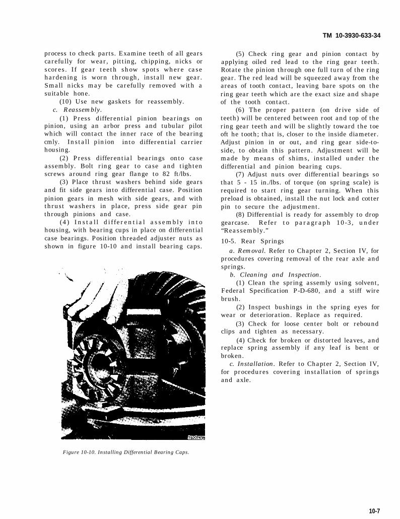
TM 10-3930-633-34
process to check parts. Examine teeth of all gearscarefully for wear, pitting, chipping, nicks orscores. If gear teeth show spots where casehardening is worn through, install new gear.Small nicks may be carefully removed with asuitable hone.
(10) Use new gaskets for reassembly.c. Reassembly.
(1) Press differential pinion bearings onpinion, using an arbor press and tubular pilotwhich will contact the inner race of the bearingcmly. Install pinion into differential carrierhousing.
(2) Press differential bearings onto caseassembly. Bolt ring gear to case and tightenscrews around ring gear flange to 82 ft/lbs.
(3) Place thrust washers behind side gearsand fit side gears into differential case. Positionpinion gears in mesh with side gears, and withthrust washers in place, press side gear pinthrough pinions and case.
(4) Install differential assembly intohousing, with bearing cups in place on differential
(5) Check ring gear and pinion contact byapplying oiled red lead to the ring gear teeth.Rotate the pinion through one full turn of the ringgear. The red lead will be squeezed away from theareas of tooth contact, leaving bare spots on thering gear teeth which are the exact size and shapeof the tooth contact.
(6) The proper pattern (on drive side ofteeth) will be centered between root and top of thering gear teeth and will be slightly toward the toeoft he tooth; that is, closer to the inside diameter.Adjust pinion in or out, and ring gear side-to-side, to obtain this pattern. Adjustment will bemade by means of shims, installed under thedifferential and pinion bearing cups.
(7) Adjust nuts over differential bearings sothat 5 - 15 in./lbs. of torque (on spring scale) isrequired to start ring gear turning. When thispreload is obtained, install the nut lock and cotterpin to secure the adjustment.
(8) Differential is ready for assembly to dropgearcase. Refer to paragraph 10-3, under“Reassembly.”
case bearings. Position threaded adjuster nuts as 10-5. Rear Springsshown in figure 10-10 and install bearing caps.
a. Removal. Refer to Chapter 2, Section IV, forprocedures covering removal of the rear axle andsprings.
b. Cleaning and Inspection.(1) Clean the spring assemly using solvent,
Federal Specification P-D-680, and a stiff wirebrush.
(2) Inspect bushings in the spring eyes forwear or deterioration. Replace as required.
(3) Check for loose center bolt or reboundclips and tighten as necessary.
(4) Check for broken or distorted leaves, andreplace spring assembly if any leaf is bent orbroken.
c. Installation. Refer to Chapter 2, Section IV,for procedures covering installation of springsand axle.
Figure 10-10. Installing Differential Bearing Caps.
10-7

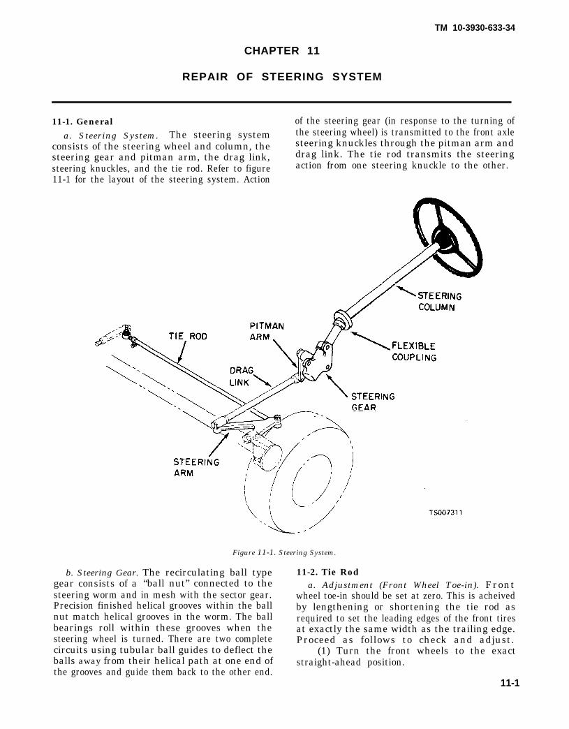
TM 10-3930-633-34
CHAPTER 11
REPAIR OF STEERING SYSTEM
11-1. General of the steering gear (in response to the turning ofa. Steering System. The steering system the steering wheel) is transmitted to the front axle
consists of the steering wheel and column, the steering knuckles through the pitman arm andsteering gear and pitman arm, the drag link, drag link. The tie rod transmits the steeringsteering knuckles, and the tie rod. Refer to figure action from one steering knuckle to the other.11-1 for the layout of the steering system. Action
Figure 11-1. Steering System.
b. Steering Gear. The recirculating ball typegear consists of a “ball nut” connected to thesteering worm and in mesh with the sector gear.Precision finished helical grooves within the ballnut match helical grooves in the worm. The ballbearings roll within these grooves when thesteering wheel is turned. There are two completecircuits using tubular ball guides to deflect theballs away from their helical path at one end ofthe grooves and guide them back to the other end.
11-2. Tie Roda. Adjustment (Front Wheel Toe-in). Front
wheel toe-in should be set at zero. This is acheivedby lengthening or shortening the tie rod asrequired to set the leading edges of the front tiresat exactly the same width as the trailing edge.Proceed as follows to check and adjust.
(1) Turn the front wheels to the exactstraight-ahead position.
11-1

Figure 11-2.
TM 10-3930-633-34
(2) Check the toe-in of front wheels after (3) Actual toe-in measurements should berolling the truck ahead one full revolution of the taken at hub-height, between the two points onwheels (with only the weight of the truck on the the center of the tread at the rear of the tires. Seetires).
—figure 11-2.
(4) Mark the point and roll the truck aheadso that the points are in the front at hub-heightand measure the distance between the same twopoints on the tire treads.
(5) The difference in the two measurementsis the actual toe-in or toe-out.
(6) To adjust the toe-in, turn the steeringwheel so that the gear is in the mid-position.
(7) Loosen the clamping bolts on the ends ofthe tie rod.
(8) Rotate the tie rod in the directionnecessary to bring toe-in within the specifiedrange (zero).
(9) Tighten the clamp bolts on the tie rodends.
b. Removal. The tie rod is secured to the axleat each end by a nut and cotter pin on the end ofeach ball stud. To remove the tie rod, removecotter pins and nuts and tap the ball stud endsfree of the steering arms.
c. Disassembly, Repair and Reassembly.(1) Loosen clamps on each tie rod end, and
unscrew and remove the tie rod ends from thetube.
(2) Remove clamp and clamp bolts.
(3) Clean all parts in solvent, FederalSpecification P-D -680.
(4) Check for cracks, dents, corrosion, and inparticular, wear and damaged threads. Replaceall worn or defective parts.
(5) Reassemble clamps on tie rod tube andinstall tie rod ends. Do not tighten clamps, as tierod ends will have to be adjusted at assemblywith axle.
d. Installation. Install tie rod to front axle,and secure ball studs in steering arms by in-stalling castellated nut and cotter pins. Adjusttoe-in as outlined in subparagraph a. Lubricate inaccordance with LO 10-3930-633-12.
11-3. Steering Geara. Removal. Refer to Chapter 2, Section IV, for
complete removal procedures.b. Disassembly.
NOTEAs with any ball bearing unit, the steering gear partsmust be kept free of dirt. Clean paper or rags shouldbe spread on the bench before starting disassembly ofthe steering gear.
Refer to figure 11-3 for parts identification andproceed as follows:
11-2

TM 10-3930-633-34
1. Horn button kit2. Nut3. Steering wheel4. Upper bearing spring5. Seat6. Upper bearing7. Clamp8. Nut9. Lockwasher
(2) Loosen the
10. Cushion 19. Cup11. Connector 20. Cone12. Screw 21. Terminal assembly13. Cover 22. Cable and contact14. Screw 23. Lockwasher15. Lockwasher 24. Nut16. Adjuster, thrust 25. Seal17. Locknut 26. Bushing18. Shaft and ball nut assembly 27. Screw
Figure 11-3. Steering Gear and Column.
28.29.30.31.32.33.34,35.36.
locknut (17) on the worm terclockwise a fewbearing adjuster, and turn the adjuster coun- assembly to catch
Screw 37. Sector shaftLockwasher 38. GasketNut 39. Cover and bushingWasher 40. ScrewScrew 41. LockwasherLockwasher 42. Adjusting screwEnd cover 43. ShimHousing 44. NutPlug 45. Gasket
turns. Place a pan under thethe lubricant and remove the
11-3

TM 10-3930-633-34
three bolts (40) and washers (41) attachingcover (39) to housing (35). Remove pitmannut’ (24).
sidearm
(3) Pull the side cover (39) with the outputshaft (37) attached from the housing.
NOTE If the sector does not clear the opening in thehousing easily, turn the wormshaft by hand until thesector will pass through the opening in the housing.
(4) Remove the worm bearing adjuster (16),adjuster locknut (17) and lower bearing (20) fromhousing (35) .
(5) Pull shaft and nut assembly (18) out ofhousing from the bottom.
(6) Remove locknut (44) from lash adjusterscrew (45). Remove side cover from output shaftby turning adjuster screw clockwise. Slide ad-juster (42) and shim (43) out of slot in end ofoutput shaft (37).
c. Cleaning and Inspection.(1) With the steering gear completely
disassembled, wash all parts in cleaning solvent.Dry them thoroughly with air. With a magnifyingglass, inspect the bearings and bearing cups forsigns of indentation. Also check for any signs ofchipping or breakdown of the surface. Any partsthat show signs of damage should be replaced.
(2) Inspect all seals. Any seal that is worn orhas been removed should be replaced.
(3) Inspect the output shaft for wear andcheck the fit of the shaft in the housing bushings.
(4) Inspect the fit of the output shaft in itsbushing in the side cover. If this bushing is worn,a new side cover and bushing assembly should beinstalled.
(5) Check steering gear wormshaft assemblyfor bent or damaged shaft. Never attempt to sal-vage steering parts by welding or straightening.
d. Repair.(1) Replace side cover and bushing as an
assembly if bushing is worn.(2) Press in new output shaft bushings, if
worn.(3) Replace seals, and gaskets prior to
reassembly.(4) Replace entire ball nut and shaft if there is
evidence of sticking or binding.e. Reassembly. After a major service overhaul
where all of the lubricant has been washed out ofthe steering gear assembly, the threads of theadjuster, side cover bolts and lash adjustershould be coated with a suitable nondrying, oil-resistant sealing compound such as Permatex No.2 or equivalent. This is to prevent leakage of gearlubricant from the steering gear assembly. Thecompound should not be applied to female threads
11-4
and extreme care should be exercised in applyingthis compound to the bearing adjuster, as thecompound must be kept away from the worm-shaft bearing. Also apply steering gear lubricantto wormshaft bearings and seal, output shaft,bushings and seal, wormshaft grooves and ballnut rack teeth to provide initial lubrication.
(1) Wrap wormshaft (stub shaft) serrations with plastic (electrician’s) tape to prevent cuttingseal lip during shaft installation.
(2) With wormshaft seal, bearings andbearing cups installed and ball nut assemblyinstalled on wormshaft, slip upper ball bearingover wormshaft and insert wormshaft and nutassembly into housing, feeding end of shaftthrough upper ball bearing cup and seal.
(3) Position the lash adjuster with shim inthe slotted end of output shaft. Check the endclearance, which should not be greater than .002inch. If clearance is greater than .002 inch, asteering gear lash adjuster shim unit is available.It contains four shims: .063 inch, .065 inch, .067inch and .069 inch thick. See figure 11-4.
Figure 11-4. Lash Adjuster Clearance.
(4) After lash adjuster end clearance has beenadjusted, start output shaft pilot into bushing inside cover. Then, using a screwdriver, throughthe hole in cover, turn lash adjuster in a coun-terclockwise direction to pull output shaft pilotinto its bushing as far as it will go.
(5) Rotate wormshaft by hand until ball nutis about in the center of travel. This is to makesure that the rack and sector will engage properlywith center tooth of the sector entering centertooth space of the nut.
(6) Place a new gasket on side cover, thenpush side cover assembly, including output shaft,into place. After making sure there is come lash

TM 10-3930-633-34
with recommendedLO 10-3930-633-12.
between rack and sector teeth, assemble and (8) Fill steering geartighten side cover bolts to 25–35 ft/lbs. lubricant in accordance with
NOTE f. Installation. Refer to Chapter 2, Section IV,Be careful not to damage seal when installing output for details on installation of steering gearshaft. Good practice would be to wrap output shaft assembly.serrations with plastic (electrician’s) tape to preventcutting seal lip during shaft installation. g. Adjustment. Refer to TM 10-3930-633-12 for
(7) Install output shaft adjuster screw procedures covering thrust and lash adjustment
locknut on screw. Do not tighten at this time. of the steering gear installed in the vehicle.
11-5


TM 10-3930-633-34
CHAPTER 12
REPAIR OF FRONT AXLE AND SPRINGS
12-1. General steering knuckles pivot on delrin bushings aboutThe front axle assembly is a light truck, I-beam the king pins, and a ball thrust bearing is used
type axle. The axle is suspended on semi-elliptical between the lower thrust faces of the steeringleaf springs. King pins are a straight design, and knuckle and axle center. See figure 12-1 for detailsare held in place by tapered draw keys. The of the installation.
Figure 12-1. Front Axle Installation.
12-2. Front Axle Repair b. Disassembly.
a. Removal. Refer to Chapter 2, Section IV, for (1) Refer to figure 12-2 for parts iden-
procedures covering removal of the front axle tification and proceed as follows:
assembly.
12-1

TM 10-3930-633-34
1. Axle assemblyz. Lube fitting3. Hex nut4. Dust cover5. Tie rod end. R.H.6. Tie rod end. L.H.7. Capscrew8. Hex nut9. Lockwasher
10. Clamp11. Rod
12. Cotter pin13. Steering arm, R.H.14. Steering arm, L.H.15. Woodruff key16. Hex nut17. Cotter pin18. Hub cap19. Hex nut20. Cotter pin21. Washer22. Bearing cone
23. Hub and cups24. Cup, outer25. Stud, wheel26. Cup, inner27. Cone28. Seal29. Nut30. Cotter pin31. Ball stud32. Plug33. Key
Figure 12-2. Front Axle Assembly.
34. Key35. Knuckle pin36. Lube fitting37. Capscrew38. Hex nut39. Shim40. Bearing41. Bushing42. Steering knuckle, R.H.43. Steering knuckle, L.H.44. Axle beam
(2) Remove tie rod and parts as outlined in (4) Remove hub caps (18). RemoveChapter 11. castellated nut (19), cotter pin (20) and bearing
(3) Remove castellated nut, cotter pin and cones (22) from each end of axle.ball stud from L. H. steering knuckle (43).
12-2

TM 10-3930-633-34
(5) Pull off brake drum with bearing cups (24and 26), cone (27) and seal (28).
(6) Remove brake assemblies from steeringknuckles.
(7) Remove nuts (16), cotter pins (17) andsteering arms (14 and 13).
(8) Drive out draw keys (33 and 34) from thesmall end. Remove expansion plugs (32 ) and driveout knuckles pins (35), to free knuckles (42 and43), shims (39) and bearings (40) from axle beam(44).
c. Cleaning and Inspection.(1) Clean parts having ground and polished
surfaces, such as knuckle pins, knuckle pinsleeves, bearings and spindles, with solvent,Federal Specification P-D-680. Do not clean theseparts in a hot solution tank or with water andalkaline solutions such as sodium hydroxide,orthosilicates or phosphates.
(2) Parts should be thoroughly dried im-mediately after cleaning. Use soft, clean, lintless,absorbent paper towels or wiping rags free ofabrasive material, such as lapping compound,metal filings or contaminated oil. Bearings shouldnever be dried by spinning with compressed air.
(3) Inspect the steering knuckle thrustbearing, wheel bearing cones and cups. Replace ifrollers or cups are worn, pitted or damaged in anyway. If wheel bearing cups are to be replaced,remove from hubs with a suitable puller. Avoidthe use of drift and hammers as they may easilymutilate cup bores.
(4) Inspect the steering knuckles and replaceif indications of weakness or excessive wear isfound.
(5) Check wear of the knuckle pins andbushings. Compare with new part dimensions todetermine extent of wear.
d. Repair.(1) Repair generally consists of replacement
of defective parts.(2) Straightening of bent parts should be
done cold. Various components are heat-treatedand hot straightening would destroy some of theheat treatment.
(3) Axle centers (that are bent no more than½ inch) may be straightened cold; if bent morethan ½ inch, they should be replaced.
(4) Bent steering arms or knuckles should bereplaced rather than straightened.
e. Replacement of Knuckle Bushings. Nylonbushings are used on production axles and arealso used as a replacement for axles having thebronze type bushing. For installing nylonreplacement, proceed as follows:
(1) Split metal bushings with hacksaw anddrive bushings from knuckle.
(2) Remove nicks and burrs from knucklebushing bore and polish with medium gritabrasive.
(3) Apply chassis lube to bushings andknuckle bore and install bushings.
f. Reassembly.(1) Make certain that the knuckle pin hole in
the axle center is clean and dry.(2) Position and support the steering knuckle
assembly (41 or 42, fig. 12-2) on the axle center(43).
(3) Slide the thrust bearing (40) between thelower face of the axle center and the lower steeringknuckle yoke.
NOTEThrust bearings that are not marked “TOP” to in-dicate proper installation orientation must bepositioned with retainer lip down.
(4) Align the steering knuckle yoke holeswith axle center and thrust bearing bores.
(5) Place a jack under the lower side ofsteering knuckle yoke and raise knuckle so thatall clearance is taken up between lower yoke,thrust bearing (40) and lower face of axle centerend.
(6) Check the clearance between the top faceof upper axle center end and lower face of upperknuckle pin boss. The clearance must not exceed.005 inches. Washers and shims (39) are availablein various thicknesses to take up this clearanceand hold it within the desired .005 inch tolerance.
(7) Align flats on knuckle pin (35) with thecenterline of the draw key holes. Drive knucklepin (35) through knuckle yoke, axle center andthrust bearing, working from top of axle.
(8) Install the draw keys (33) into the axlecenter. Drive the draw key in so that the flat onthe key will mate with the corresponding flats onthe knuckle pin. Seat pin firmly in place.
(9) Install expansion plugs (32) in knucklebores, top and bottom.
(10) Reinstall backing plates and brakeassemblies, if previously removed. Also, if axleassembly was removed from truck chassis,reinstall at this time.
(11 ) Install tie rod as outlined in Chapter 11.(12) Install brake drum and hubs with
bearings in place and properly lubricated ac-cording to instructions in TM 10-3930-633-12.
(13) Axle is ready for installation.g. Installation.
(1) Refer to Chapter 2, Section IV, for in-
12-3

TM 10-3930-633-34
stallation procedures on the front axle andsprings.
(2) Adjust front wheel bearings in accordancewith procedures outlined in TM 10-3930-633.12.
(3) Lubricate axle assembly as indicated inLO 10-3930-633-12,
(4) Adjust steering stop screws as outlined inTM 10-3930-633-12.12-3. Front Springs
a. Removal. Refer to Chapter 2, Section IV, forprocedures covering removal of front axle andsprings.
b. Cleaning and Inspection.
(1) Clean the spring assembly using solvent,Federal Specification P-D-680 and a stiff wirebrush.
(2) Inspect bushings in the spring eyes forwear or deterioration. Replace as required.
(3) Check for loose center bolt or reboundclips and tighten as necessary,
(4) Check for broken or distorted leaves, andreplace spring assembly if any leaf is bent orbroken.
c. Installation. Refer to Chapter 2, Section IV,for procedures covering installation of springsand axle.
12-4

TM 10-3930-633-34
APPENDIX A
REFERENCES
A-1. Fire ProtectionTB 5-4200-200-100
A-2. LubricationC91001LLO 10-3930-633-12
A-3. PaintingTM 43-0139
A-4. Radio SuppressionFM 11-65
A-5. MaintenanceTB ORD 651
DA PAM 738-750TM 10-3930-633-12
DMWR 10-3930-633
TM 10-3930-633-20P
TM 10-3930-633-34P
TM 9-6140-200-14
TM 5-764TB 385-101
Hand Portable Fire Extinguishers Approved for Army Users
Fuels, Lubricants, Oils and WaxesLubrication Order for Tractor, Wheeled, Warehouse, Gasoline, 4-Wheel,
Pneumatic Tired, 4,000 LB DBP Clark Model 2330237 Army ModelMHE-228
Painting Instructions for Field Use
Radio Interference Suppression
Use of Antifreeze Solutions and Cleaning Compounds in Engine CoolingSystems
The Army Maintenance Management System (TAMMS)Operator and Organizational Maintenance Manual for Tractor, Wheeled,
Warehouse Gasoline, Army Model MHE-228, Clark Equipment Model2330237, NSN 3930-00-347-6173
Depot Maintenance Work Requirement for Tractor, Wheeled, Warehouse,Gasoline, 4-Wheel, Pneumatic Tired, 4,000 LB DBP, Clark Model 2330237Army Model MHE-228
Organizational Maintenance Repair Parts and Special Tools List for Tractor,Wheeled, Warehouse, Gasoline, 4-Wheel, Pneumatic Tired, 4,000 LBDrawbar Pull (Clark Equipment Co., Model 2330237), Army ModelMHE-228
Direct Support and General Support Maintenance Repair Parts and SpecialTools List for Tractor, Wheeled, Warehouse, Gasoline, 4-Wheel, PneumaticTired, 4,000 LB DBP, (Clark Equipment Co., Model 2330237) ArmyModel MHE-228
Operator’s, Organizational, Direct Support and General Support MaintenanceManual for Lead-Acid Storage Batteries
Electric Motor and Generator RepairSafety Use of Cranes, Crane-Shovel Dragline, and Similar Equipment Near
Electric Power LinesA-6. Shipment and Storage
TB 740-93-2 Preservation of USAMEC Mechanical Equipment for Shipment and StorageTM 740-90-1 Administrative Storage of Equipment
A-7. Destruction of Army Materiel to Prevent Enemy UseTM 750-244-6 Procedures for Destruction of Tank-Automotive Equipment to Prevent Enemy
UseA-8. Safety
TB MED 501 Occupational and Environmental Health: Hearing ConservationTB 750-1047 Elimination of Combustibles from Interiors of Metal or Plastic Gasoline and
Diesel Fuel Tanks
Change 1 A-1 /(A-2 Blank)

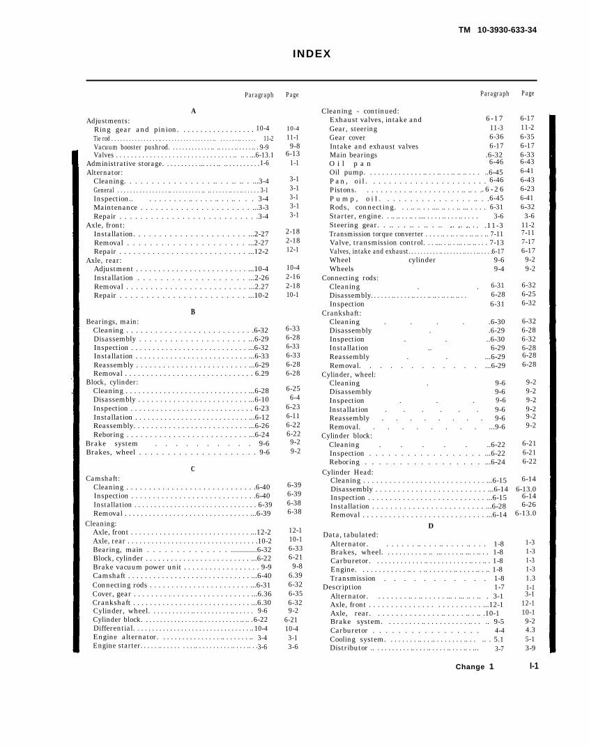
TM 10-3930-633-34
INDEX
Paragraph
AAdjustments:
Ring gear and pinion. . . . . . . . . . . . . . . . . . 10-4Tie rod . . . . . . . . . . . . . . . . .. . . . . . . . . . . . . . . . . . .. . . . . . . .. . . . . . 11-2Vacuum booster pushrod. . . . . . . . . . . . . .. .. . . . . .. . . . . .. . 9-9Valves . . . . . . . . . . . . . . . . . . . . . . . . . . . . . . . .. .. . ...6-13.1
Administrative storage. . . . . . . . . . ... . . . .. .. . . . . . . . . .1-6Alternator:
Cleaning. . . . . . . . . . . . . . . . .. . . .. .. . ...3-4General . . . . . . . . . . . . . . . . .. . . . . . . . . . .. .. . . . . . .. . . .. . . . . . 3-1Inspection.. . . . . . . . . .. . . . . .. . . .. . . . 3-4Maintenance . . . . . . . . . . . . . . . . . . . . . . ...3-3Repair . . . . . . . . . . . . . . . . . . . . . . . . . . .3-4
Axle, front:Installation. . . . . . . . . . . . . . . . . . . . . . ...2-27Removal . . . . . . . . . . . . . . . . . . . . . ...2-27Repair . . . . . . . . . . . . . . . . . . . . . . . . . . . ...12-2
Axle, rear:Adjustment . . . . . . . . . . . . . . . . . . . . . . . . . ...10-4Installation . . . . . . . . . . . . . . . . . . . ...2-26Removal . . . . . . . . . . . . . . . . . . . . . . . . . ...2.27Repair . . . . . . . . . . . . . . . . . . . . . . . . ...10-2
BBearings, main:
Cleaning . . . . . . . . . . . . . . . . . . . . . . . . . . .6-32Disassembly . . . . . . . . . . . . . . . . . . . . . ...6-29Inspection . . . . . . . . . . . . . . . . . . . . . . . . . . . ...6-32Installation . . . . . . . . . . . . . . . . . . . . . . . . . . ...6-33Reassembly . . . . . . . . . . . . . . . . . . . . . . . . . ...6-29Removal . . . . . . . . . . . . . . . . . . . . . . . . . . . . . . 6.29
Block, cylinder:Cleaning . . . . . . . . . . . . . . . . . . . . . . . . . . . . . ...6-28Disassembly . . . . . . . . . . . . . . . . . . . . . . . . . ...6-10Inspection . . . . . . . . . . . . . . . . . . . . . . . . . . . . . 6-23Installation . . . . . . . . . . . . . . . . . . . . . . . . . . . ...6-12Reassembly. . . . . . . . . . . . . . . . . . . . . . . . . . ...6-26Reboring . . . . . . . . . . . . . . . . . . . . . . . . . . ...6-24
Brake system . . . . . . . . . . 9-6Brakes, wheel . . . . . . . . . . . . . . . . . . . . . 9-6
CCamshaft:
Cleaning . . . . . . . . . . . . . . . . . . . . . . . . . . . . .6-40Inspection . . . . . . . . . . . . . . . . . . . . . . . . . . . . .6-40Installation . . . . . . . . . . . . . . . . . . . . . . . . . . . . . . . 6-39Removal . . . . . . . . . . . . . . . . . . . . . . . . . . . . . . . ...6-39
Cleaning:Axle, front . . . . . . . . . . . . . . . . . . . . . . . . . . . . . ...12-2Axle, rear . . . . . . . . . . . . . . . . . . . . . . . . . . . . . . . . .10-2Bearing, main . . . . . . . . . . . . . . .............6-32Block, cylinder . . . . . . . . . . . . . . . . . . . . . . . . . ...6-22Brake vacuum power unit . . . . . . . . . . . . . . . . . . 9-9Camshaft . . . . . . . . . . . . . . . . . . . . . . . . . . . . . ...6-40Connecting rods . . . . . . . . . . . . . . . . . . . . . . . ...6-31Cover, gear . . . . . . . . . . . . . . . . . . . . . . . . . . . ...6.36Crankshaft . . . . . . . . . . . . . . . . . . . . . . . . . . . . ...6.30Cylinder, wheel. . . . . . . . . . . .. . . . . . . . . . .. . . . . . 9-6Cylinder block. . . . . . . . . . . . . . . . .. . . . . . . . . . . .. .. . 6-22Differential. . . . . . . . . . . . . . . . . . . . . . . . . . . . . . . . ..10-4Engine alternator. . . . . . . . . . . . . . . . .. . . . . . . .. 3-4Engine starter. . . . . .. . . . . . . . . .. . . . . . . . . . .. . . . .. . . .3-6
Page
10-411-19-8
6-131-1
3-13-13-13-13-1
2-182-1812-1
10-42-162-1810-1
6-336-286-336-336-286-28
6-256-4
6-236-116-226-229-29-2
6-396-396-386-38
12-110-16-336-219-8
6.396-326-356-329-2
6-2110-43-13-6
Paragraph
Cleaning - continued:Exhaust valves, intake and 6-17Gear, steering 11-3Gear cover 6-36Intake and exhaust valves 6-17Main bearings .6-32O i l p a n 6-46Oil pump. . . . . . . . . . . . . . .. . . .. . . .. .. .. . . . ..6-45Pan, o i l . . . . . . . . . . . . . . . . . . . . . . . 6-46Pistons. . . . . . . . . . .. . . . . . . . . . . .. .. . .. 6 - 2 6P u m p , o i l . . . . . . . . . . . . . . . . .. . .6-45Rods, connecting. . . .. .. . . .... .. . . .. ... . . . . 6-31Starter, engine. . .. .. . . .. . .... . . . . .. . . . .. . . . . 3-6Steering gear. . .. . . .. . .. . .. .. .. . .. . .. . .11-3Transmission torque converter . . . . .. . .. . .. . .. .. . .. 7-11Valve, transmission control. . . .... . .. . ... . .. .. . . . 7-13Valves, intake and exhaust. . . . . . . . . . .. . . . . . . .. . . . .. . . . . 6-17Wheel cylinder 9-6Wheels 9-4
Connecting rods:Cleaning . . 6-31Disassembly. . . . . . .. . . . . .. . . . .. .. . .. . .. .. . . 6-28Inspection 6-31
Crankshaft:Cleaning . . . . .6-30Disassembly . .6-29Inspection . . ..6-30Installation .. 6-29Reassembly . . ...6-29Removal. . . . . . . . . . . . ...6-29
Cylinder, wheel:Cleaning . 9-6Disassembly 9-6Inspection . . . 9-6Installation . . . . . . 9-6Reassembly . . . . . . . . 9-6Removal. . . . . . . . . ...9-6
Cylinder block:Cleaning . . . . . ..6-22Inspection . . . . . . . . . . . . . . . . . . ...6-22Reboring . . . . . . . . . . . . . . . . . ...6-24
Cylinder Head:Cleaning . . . . . . . . . . . . . . . . . . . . . . . . . . . . ...6-15
Page
6-1711-26-356-176-336-436-416-436-236-416-323-6
11-27-117-176-179-29-2
6-326-256-32
6-326-286-326-286-286-28
9-29-29-29-29-29-2
6-216-216-22
6-14Disassembly . . . . . . . . . . . . . . . . . . . . . . . . . ...6-14 6-13.0Inspection . . . . . . . . . . . . . . . . . . . . . . . . . . . ...6-15Installation . . . . . . . . . . . . . . . . . . . . . . . . . ...6-28Removal . . . . . . . . . . . . . . . . . . . . . . . . . . . . ...6-14
DData, tabulated:
Alternator. . . . . . . .. . . . .. . . . . .. . . . 1-8Brakes, wheel. . . . . . . . . . .. .. ... . . . . .. ... . .. . . 1-8Carburetor. . . . . . . . . . . . . .. . . . . . . . . . . .. . . .. . 1-8Engine. . . . . . . . . . . . .. . . .. . . . . . . .. . . . . .. . .. 1-8Transmission . . . . . . . . . . . 1-8
Description 1-7Alternator. . . . . . . . .. . .. . . . . . ... . ... .. . .. . 3-1Axle, front . . . . . . . . . . . . . . . . . . . . . . . . . ...12-1Axle, rear. . . . . . . . . . . . . . . .. . . . . .. . .. .10-1Brake system. . . . . . . . . .. . . . . . . . . . . .. . . .. 9-5Carburetor . . . . . . . . . . . . . . . . . 4-4Cooling system. . . . . . . . .. . . .. . . . . . . . .. . . .. . 5.1Distributor .. . . . . . . . . . .. . . . .. . . . . .. . . . .. . ... 3-7
Change 1
6-146-26
6-13.0
1-31-31-31-31.31-13-1
12-110-19-24.35-13-9
I-1

Paragraph
6-38
TM 10-3930-633-34
Description - continued:Engine 6-1Fuel system 4-1Propeller shaft 8-1Starter 3-5Torque converter 7-11Transmission 7-1
Differences in models 1-9Differential:
Cleaning.. . . . . . .. . . . . . .. . . . . . . . . . . .. . . . . . 10-4Disassembly. . . . . . . . . . . . . .. . . . .. . . . . . . . .. . 10-4Inspection . . . .. . . . . . . . .. . . . .. .. ... . 10-4Reassembly. .. . . . . . . .. . . . . . . . . .. . . 10-4
Direct support, general supportand depot maintenancerepair parts.... . . . . . . ... . . . ... . . ..... . . .. . .. .. . 2-2
Disassembly:Alternator . . . . . . . . . . . . . . . . . . . . . . 3-4Axle, front, . . . . . . . . . . . . . . . ...12-2Axle, rear . . . . . . . . . . . . . . . . . . . . . . . . . . . . ...10-2Bearings, main . . . . . . . . . . . . . . . . . . . . . . . . ...6-29B r a k e s
Cylinder bead
9-6
6-14Distributor 3-8Engine . . . . . . . . . . . . . . . . . . . . . . . . . 6-10Oil pump . . . . . . . . . . . . . . . . . . . . . . . . . . . . ...6-45Propeller shaft . . . . . . . . . . . . . . . . . . . . . . . . . . 8-3Starter . . . . . . . . . . . . . . . . . . . . . . . . . . 3-6Steering gear . . . . . . . . . . . . . . . . . ...11-3Transmission: . . . . . . . . . . . . . . . . . . . . . . . . . ...7-12
Control valve body . . . . . . . . . . . . . . . . . ...7-13Extension housing . . . . . . . . . . . . . . . . . . 7-16Front clutch . . . . . . . . . . . . . . . . . . . . . . . . ...7-23Front pump . . . . . . . . . . . . . . . . . . . . . . . ..7-20Front servo . . . . . . . . . . . . . . . . . . . . . .7-14Governor . . . . . . . . . . . . . . . . . . . . . . . . . . . . ...7-17Pressure regulator . . . . . . . . . . . . . . . . . . . . ...7-18Rear clutch . . . . . . . . . . . . . . . . . . . . . . . . . . ...7-22Rear pump . . . . . . . . . . . . . . . . . . . . . . . . . . . ...7-21Rear servo . . . . . . . . . . . . . . . . . . . 7 -15
Vacuum booster . . . . . . . . . . . . . . . . . . ... .. 9-9Distributor:
Cleaning . . . . . . . . . . . . . . . . . . . . . . . . . . . . . . . 3-8Disassembly . . . . . . . . . . . . . . . . . . . . . . . . . . . . . . 3-8Inspection . . . . . . . . . . . . . . . . . . . . . . . ... .. 3-8Reassembly . . . . . . . . . . . . . . . . . . . . . . . ... .... .. 3-8Repair . . . . . . . . . . . . . . . . . . . . . . . . . . . . .. .. 3-8
EEngine:
Assembly ............................ . . . . . ...6-12Bearings, main . . . . . . . . . . . . . . . . . . . . . . . . . ...6-32Block, cylinder . . . . . . . . . . . . . . . . . . . ...........6-22Camshaft . . . . . . . . . . . . . . . . . . . . . . . . . . . . . . ...6-37Connecting rods . . . . . . . . . . . . . . . . . . . . . . . . ...6-31Cover, front . . . . . . . . . . . . . . . . . . . . . . ., . . . . ...6.36Crankshaft, . . . . . . . . . . . . . . . . . . . . . . . . . . ...6-29Cylinder block.. . . . . .. .. . .. . .. . ... . . . . .. . . . . .. . . . . . .. ...6-22Cylinder head . . . . . . . . . . . . . . . . . . . . . . . . ...6-13Exhaust valves . . . . . . . . . . . . . . . . . . . . . . . . . ...6-17Gears, timing . . . . . . . . . . . . . . . . . . . . . . . . . . ...6-37Installation, , . . . . . . . . . . . . . . . . . . . . .. . .. . . . ...2-24Intake valves . . . . . . . . . . . . . . . . . . . .. . . . . . ...6-17Main bearings . . . . . . . . . . . . . . . . . . . . . . . . . . 6-32Oil pan ....... .. . . . . . . .. . . . . .. . . . . . .. . .. . ... 6-43Oil pump .. . . . . . . . . .. . . .. . .. . . .. . . .. . . . . . ...6-45
Page
6-14-18-13-6
7-117-11-4
10-410-410-410-4
2-1
3-112-110-16-28
9-2
6-133-10
6-46-41
8-13-6
11-27-117-177-227-287-267-207-237-247.277-277-219-8
3-103-103-103-103-10
6-116-336-216-366.326-356-286-216-136-176-362-136-176-336-416-41
Paragraph
Engine - continued:Pan, oil 6 - 4 3Pistons 6-26Pump, oil 6-45Removal 2-24Rods, connecting 6-31Tabulated data 1-8Valves, exhaust 6-17Valves, intake 6-17
FForms and records 1-2Front axle 12-2Fuel tank 4-2
GGear, steering: . . . . . .. . .. . . .. . . . ... . . .11-3
Installation . . . . . . . . . . 2 - 2 9Removal . . . . .. . . . . .. . . . . . .. . . . . . . . .. . .. . ...2-29Repair. . . . . .. . . .. .. . . . . . . . . . . . .. 11-3
General cleaning . . . . . . . . . . . .. . . .. . . . .. . . .. .2-7General disassembly.. . . . . . . .. . . . . .... .. .. 2-6G e n e r a l i n s p e c t i o n . . . . 2-8General reassembly . . . ..2-10General removal . . . . . . . . . . . . . . 2-5General repair . . . . . . . . . . . . . . . . 2-9Governor . . . . . . . . . . . . . . . . . . . . . . . . . . . . ...7-17
IInspection:
Alternator . . . . . . . . . . . . . . . . . . . . 3-4Axle, front . . . . . . . . . . . . . . . . . . . . . 12-2Axle, rear . . . . . . . . . . 10-2Bearings, main . . . . . . . . . . . . . . . . . . . . . ...6-32Block, cylinder . . . . . . . . . . . . . . . . . . . . 6-23Brakes 9-6Camshaft . . . . . . . . . . . . . . . . . ...6-40
Crankshaft . . . . . . . . . . . . . . . . . . . . . . . . . . . . . ...6-30Connecting rods . . . . . . . . . . . . . . . . . . . . . . . . ...6-31Cylinder head . . . . . . . . . . . . . . . . . . . . . . . . . ...6-15Cylinder, wheel . . . . . . . . .. .. . . . .. .. . . . . . . . . . . . . . . . . . . . ...’.. 9-6Differential. . . . . . . .. . . . .. . . .. . . . . ...10-4Engine . . . . . . . . . . . . . . . .. . . .. .. . .. .6-11Fuel tank, . . . . . . . . . . . . . . . . . . . . . . . 4.2Gear, steering.. . . . . . . . . . . . . . . . . . . . . . . . ...11-3Governor . . . . . . . . . . . . . . . . . . . . . . . . . . . . . . ...7-17Main bearings . . . . . . . . . . . . . . . . . . . . . . . . . . ...6-32oil can . . . . . . . . . . . . . . . . . . . . . . . . . . . . . . . . ...6-46Oil pump . . . . . . . . . . . . . . . . . . . . . . . . . . . . . . ...6-45Pistons . . . . . . . . . . . . . . . . . . . . . . . . . . . . . . ...6-26Pump, oil.................. . . . . . ...6-45Radiator . . . . . . . . . . . . . . . . . . . . . . . . . . . 5-3Rod, connecting . . . . . . . . . . . . . . . . . . ..6-31Spring, front . . . . . . . . . . . . . . . . . . . . . ...12-3Spring, rear . . . . . . . . . . . . . . . . . . . . . . . . . . . . . ... . . .. . .. . 10-5Starter . . . . . . . . . . . . . . . . . . . . . . . . 3-6Steering gear.............. . . . . . .. . . . .. .. . .. ... ... .. . ..11-3Tie rod...................... .. . . . . . .. . .. . . .. . . .. . . . . . . .. . . .. ....11-2Torque converter . . . . . . . . . . . . . . . . . . . . . . . ...7-11Transmission . . . . . . . . . . . . . . . . . . . 7-24
Installation:Axle, front............... . . . . . .. . . . . . .. . . .. .. . .. . .. . .. . .. ...2-27Axle, rear . . .. .. . . .. . . . . . . . . . . . . . . . . . . . . . . . 2-26Bearings, main . .......... . . .. . . .... . ... .. . . . . .. . .. . . . . ...6-33Camshaft ................... . . . . . . ...6-39
Page
6-416-236-412-136-32
1-36-176-17
1-112-14-3
11-22-192-1911-22-72-72-8
2-102-72-9
7-23
3-112-110-16-336-219-2
6-39
6-326-326-14
9-210-46-10
4-311-27-236-336-436-416-236-41
5-16-3212-410-73-6
11-211-17-117-31
2-182-166-33
I-2 Change 1

Paragraph
Installation - continued:Crankshaft . . . . . . . . . . . . . . . . . . . . . . . . . . . . ...6-29 Cylinder head . . . . . . . . . . . . . . . . . . . . . . . . . . . 6-28Differential . . . . . . . . . . . . . . . . . . . . . . . . . . . ...10-4Engine . . . . . . . . . . . . . . . . . . . . . .2-24Fuel tank . . . . . . . . . . . . . . . . . . . . . . . . . . . . . . . . . 4-2Governor......................:.. . . . . . ...7-17Gears, timing . . . . . . . . . . . . . . . . . . . . . . . . . . ...6-39Intake and exhaust valves . . . . . . . . . . . . . . ...6-21Main bearings . . . . . . . . . . . . . . . . . . . . . . . . . . ...6-32Oil pan . . . . . . . . . . . . . . . . . . . . . . . . . . . . . . ...6-43Oil pump . . . . . . . . . . . . . . . . . . . . . . . . . . ...6-44Pistons . . . . . . . . . . . . . . . . . . . . . . . . . . . . . . . ...6-26Pump, oil . . . . . . . . . . . . . . . . . . . . . . . . . . . . . ...6-44Rear axle . . . . . . . . . . . . . . . . . . . . . . . . . . , . . ...2-26Rods, connecting . . . . . . . . . . . . . . . . . . . . . . ...6.28Steering gear . . . . . . . . . . . . . . . . . . . . . . . . . . . . . 2.29Three . . . . . . . . . . . . . . . . . . . . . . . . . . . . . . . . . . . . 9-2Torque converter . . . . . . . . . . . . . . . . . . . . . . ...7-11Transmission . . . . . . . . . . . . . . . . . . . . . . . . . . ...2-25Valves . . . . . . . . . . . . . . . . . . . . . . . . . . . . . . . ...6-21
MMain bearings:
Cleaning . . . . . . . . . . . . . . . . . . . . . . . . . . . ., . ...6-31Inspection . . . . . . . . . . . . . . . . . . . . . . . . . . . . ...6-32Installation . . . . . . . . . . . . . . . . . . . . . . . . . . . ...6-33
Manifold vacuum test, . . . . . . . . . . . . . . . . . . . . . . 6-7Main seals . . . . . . . . . . . . . . . . . . . . . . . . . . . . . . ...6-36
oOil pan . . . . . . . . . . . . . . . . . . . . . . . . . . . . . . . . ...6-43
Cleaning . . . . . . . . . . . . . . . . . . . . . . . . . . . . . . ...6-46Inspection . . . . . . . . . . . . . . . . . . . . . . . . . . . . ...6-46Installation . . . . . . . . . . . . . . . . . . . . . . . . . . . ...6.43Removal . . . . . . . . . . . . . . . . . . . . . . . . . . . . . . . ...6-43
Oil pump:Cleaning . . . . . . . . . . . . . . . . . . . . . . . . . . . . . . . ..6-45Inspection . . . . . . . . . . . . . . . . . . . . . . . . . ...6-45Installation . . . . . . . . . . . . . . . . . . . . . . . . . . . . ...6-44Removal . . . . . . . . . . . . . . . . . . . . . . . . . ...6-44Repair . . . . . . . . . . . . . . . . . . . . . . . . . ...6-45
PPan, oil:
Cleaning . . .6-46Inspection . . . . . . . . . . . . . . . . . . . . . . ...6-46Installation . . . . . . ...6-43Removal . . . . . . . . .6-43
Pistons:Cleaning . . .. 6-26Inspection . . . . . . . . . . . . . . .. 6-26Installation . . . ...6-28
Pump, oil:Cleaning . . . . ...6-45Inspection . . . . . . . . . . . . . . . . . . ...6-45Installation . . . . . . . . . . . . . . . . . ..6-44Removal . . . . . . . . . . . . . . . . . . . . . . . . . . .6-44Repair . . . . . . . . . . . . . . . . ...6-45
RRadiator 5-3Rear axle:
Cleaning . . . . . . . . . . . . . . . . . . . . . . . . . . . . ...10-2General . . . . . . . . . . . . . . . . . ...10-1Inspection . . 10-2Installation . . . . . . . . . . . . . . . . . . . . . . . ...2-26
Page
6-386-2610.42-134.1
7-236-386-206-336-416-416-256-412-166-252-199-1
7-112-146-20
6-326-336-33
6-26-35
6-416-436-436-416-41
6-416-416-416-416-41
6-436-436-416-41
6.236.236.25
6-416-416-416.416-41
5-1
10-110-110-12-16
TM 10-3930-633-34
Paragraph Page
Rear axle . continued:Removal . . . . . . . . . . . . . . . . . . . . . . . . . . . . . . ...2-26Repair . . . . . . . . . . . . . . . . . . . . . . . . . . . . . ...10-2
Rear springs:Cleaning . . . . . . . . . . . . . . . . . . . . . . . . . . . . . . ...10-5Inspection . . . . . . . . . . . . . . . . . . . . . . . . . . . . ...10-5Installation . . . . . . . . . . . . . . . . . . . . . . . . . . . ...2-26Removal . . . . . . . . . . . . . . . . . . . . . . . . . . 2-26
Reassembly:Alternator . . . . . . . . . . . . . . . . . . . . 3-4Axle, front . . . . . . . . . . . . . . . . . . . . . . . . . . . . ...12-2Axle, rear . . . . . . . . . . . . . . . . . . . . . . . . . . . ...10-2Bearings, main . . . . . . . . . . . . . . . . . . . . . . . . ...6-29Brakes . . . . . . . . . . . . . . . . . . . . . . . . . . . . . . . . . .9-6
Cylinder head . . . . . . . . . . . . . . . . . . . . . . . 6-28Distributor . . . . . . . . . . . . . . . . . . . . . . . . . . . . . 3-8Engine . . . . . . . . . . . . . . . . . . . . . . . . . . . . . . . ...6-10Oil pump . . . . . . . . . . . . . . . . . . . . . . . . . . . . . ...6-45Propeller shaft . . . . . . . . 8-3Starter . . . . . . . . . . . . . . . . . . . . . . . . . . . . . . . . . . 3-6Steering gear . . . . . . . . . . . . . . . . . . . . . . . . ...11-3Transmission: . . . . . . . . . . . . . . . . . . . . . . . . . ...7-12
Control valve body . . . . . . . . . . . . . . . . . . ...7-13Extension housing . . . . . . . . . . . . . . . . . . . . ...7-16Front clutch . . . . . . . . . . . . . . . . . . . . . . . . ...7-23Front pump . . . . . . . . . . . . . . . . . . . . . . . . . ...7-20Front servo . . . . . . . . . . . . . . . . . . . . . .. .7-14Governor . . . . . . . . . . . . . . . . . . . . . . . . . . . ...7-17Pressure regulator . . . . . . . . . . . . . . . . . . ...7-18Rear clutch . . . . . . ...7-22Rear pump . . . . . . . . . . . . . . . . . . . . . . . ...7-21Rear servo . . . . . . . . . . . . . . . . . . . . . ...7-15
Vacuum booster .. . . . . . . . . .. . .. .. . .. . .. .9-9Records, forms and . . . . . .. ... .. . ... .. .. . . ..1-6Refinishing cylinder walls. . . . . . .. . . . . .. . .. . .. .. . . 6-24Removal:
Axle, front . . . . . . . . . . . . . . . . . . . . . . . . . . ...2-27Axle, rear . . . . . . . . . . ... . . . .. . . . . . . . .. . ....2-26Bearings, main . . . . . . . . . . . . . . . . . . . . . . . ...6-29Brakes . . . . . . . . . . . . . . . . . . . . . . . . . . . . .. .. . 9-6Camshaft . . . . . . . . ...6-39Cylinder head.. .. . . . . . ... . . . . . . . ... .. . 6-14Crankshaft . . . . . . . . . . . . . . . . . . . . . . . . . ...6-29Engine . . . . . . . . . . . ... . . . .. . . .. . .. . . ..2-24Fuel tank.... . . . . . . . . . . . 4-2Oil can . . . . . . . . . . . . . . . . . . . . . . . . . . . . . . . ...6-43Oil pump . .. . . . . .. . . . . . . . . . . . . ..6-44Propeller shaft .. . . . . . .. .. . . . .8-2Steering gear.... . . . . .. . . . .. . . .. .. .. . ...2-29Transmission . . . . . . . . . . ...2-25Vacuum boos ter . . . . . . 2 - 2 8Valves . . . . ...6-14
Repair:Alternator 3 - 4Axle, front.. . .. . . . . . .. . . . . .. . . .. . . . .. . .. . . ...12-2Axle, rear . . . . . ...10-2B r a k e s 9-6Cylinder head 6-16Distributor 3-8Fuel tank 4-2Oil pump 6-45Propeller shaft. . . . . .. . . .. . . . .. . . . . . .8-3Starter.. . ... .. . . . .. . . . .. . . . . .. . .. ... . 3-6Steering gear. . . . . . . . . .. . . .. .. . 11-3Tie rod . .. . . .. . . . . . . . . . . .. . .. ...11-2
Change 1
2-1610-1
10-710-72-162-16
3-112-110-16-28
9-2
6-283-10
6-46-41
8-13-6
11-27-117-177-227-287-267-207-237-247-277-277-219-81-1
6-22
2-182-166-28
9-26-38
6-13.06-282-134-3
6-416-418-1
2-192-142-196-13
3-112-110-19-2
6-153-10
4-36-418-13-6
11-211-1
I-3

Page
TM 10-3930-633-34
Paragraph
Repair -continued:Transmission . . . . . . . . . . . . . . . . . . . . . . . . . ...7-12
Control valve body . . . . . . . . . . . . . . . . . . ...7-13Extension housing . . . . . . . . . . . . . . . . 7-16Front clutch . . . . . . . . . . . . 7-23Front pump . . . . . . . . . . . . . . . . . . . . . . 7-20Governor . . . . . . . . . . . . . . 7-17Pressure regulator . . . . . . . . . . . . . . . . . . ...7-18Rear clutch . . . . . . . . . . . . . . 7-22Rear pump . . . . . . . . . . . . . . . . . . . . . . . 7-21Rear servo . . . . . . . . . . . . . . . . . . . . . . 7-15
Vacuum booster. . . . . . . . . . . . . . . . . 9-9
sStarter:
General . . . . . . . . . . . . . . . . . . . . . . . . . . . . . . 3-5Repair . . . . . . . . . . . . . . . . . . . . . . . . . . . . . . . . 3-6
Steering gear:Cleaning . . . . . . . . . . . . . . . . . . . . . . . . . . . . . . ...11-3Disassembly . . . . . . . . . . . . . . . . . . . . . . . . . . ...11-3Inspection . . . . . . . . . . . . . . . . . . . . . . . . . . . . ...11-3Installation . . . . . . . . . . . . . . . . . . . . . . . . . . . ...2-29Reassembly . . . . . . . . . . . . . . . . . . . . . . . . . . . ...11-3Removal . . . . . . . . . . . . . . . . . . . . . . . . . . . . . . . ...2-29Repair . . . . . . . . . . . . . . . . . . . . . . . . . . . . . . . ...11-3
TTie rod:
Cleaning . . . . . . . . . . . . . . . . . . . . . . . . . . . . . . ...11-2Inspection . . . . . . . . . . . . . . . . . . . . . . . . . . . . ...11-2Installation . . . . . . . . . . . . . . . . . . . . . . . . . . . ...11-2Removal . . . . . . . . . . . . . . . . . . . . . . . . . . . . . ...11-2
Tires . . . . . . . . . . . . . . . . . . . . . . . . . . . . . . . . 9-3Torque converter:
Cleaning . . . . . . . . . . . . . . . . . . . . . . . . . . . . . ...7-11Inspection . . . . . . . . . . . . . . . . . . . . . . . . . . . . ...7-11Installation . . . . . . . . . . . . . . . . . . . . . . . . . . . ...7-11Removal . . . . . . . . . . . . . . . . . . . . . . . . . . . 7-11
Transmission:Adjustment . . . . . . . . . . . . . . . . . . . . . . . 7-5
Page
7-117-177-227-287-267-237-247-277-277-219-8
3-63-6
11-211.211-22-1911-22-1911-2
11-111-111-111-19-2
7-117-117-117-11
7-5
Paragraph
Transmission - continued:Air pressure checks . . . . . . . . . . . . . . . 7-8Component inspection . . . . . . . . . . . . . . . . . . . . 7-24Control pressure check . . . . . . . . . 7-7Control valve body . . . . . . . . . 7-13Extension housing ...... . . . . . . ...7-16Front clutch . . . . . . . . . . . . . . . . . . . . . . . . ...7-23Front pump.................. . . . . . . . 7-20Front servo . . . . . . . . . . . . . . . . . . . . . . . . ...7-14Governor . . . . . . . . . . . . . . . . . . . . 7-I7Hydraulic control system . . . . . . . . . . . . . . 7-3Installation . . . . . . . . . . . . . . . . . . . . . . . . . . . . . 2-25Leakage checks . . . . . . . . . . . . . . . . . . . . . . . . 7-9Manual linkage . . . . . . . . . . . . . . . . . . . . . . 7-19Pressure regulator . . . . . . . . . . . . . . . . . . . . ...7-18Rear clutch . . . . . . . . . . . . . . . . . . . . . . . . . . . . . 7-22Rear pump . . . . . . . . . . . . . . . . . . . . . . . . . . . . . 7-21Rear servo . . . . . . . . . . . . . . . . . . . . . . . . . . . 7-15Stall test . . . . . . . . . . . . . . . . . . . . . 7-6Torque converter . . . . . . . . . . . . . . . . . . . . . . ...7-11
vValves:
Cleaning . . . . . . . . . . . . . . . . . . . . . . . . . . . . . . ...6-17Inspection . . . . . . . . . . . . . . . . . . . . . . . . . . . . ...6-17Installation . . . . . . . . . . . . . . . . . . . . . . . . . ...6-21Refacing . . . . . . . . . . . . . . . . . . . . . . . . . . . . . . ...6-18
Valve springs inspection . . . . . . . . . . . . . ...6-19
wWheels:
General . . . . . . . . . . . . . . . . . . . . . . . . . . . . . 9-1Repair . . . . . . . . . . . . . . . . . . . . . . . . . . . . . . 9-4
Wheel cylinders:Cleaning . . . . . . . . . . . . . . . . . . . . . . . . . . . . . . . . . .9-6Inspection . . . . . . . . . . . . . . . . . . . . . . . . . . . . . ...9-6Installation. . . ... . . . .. . . . . . .. . ....................9-6Repair . . . . . . . . . . . . . . . . . . . . . . . . . . . . . . . . ...9-6
7-77-31
7-67-177-227-287-267-207-237-2
2-147-8
7-257-247-277-277-21
7-67-11
6-176-176-206-186-18
9-19-2
9-29-29-29-2
I - 4 *U.S. GOVERNMENT PRINTING OFFICE: 1990 743-024/20042

TM 10-3930-633-34
By Order of the Secretary of the Army:
Official:VERNE L. BOWERSMajor General, UnitedThe Adjutant General.
Distribution:
States Army,
FRED C. WEYANDGeneral, United States Army,Chief of Staff.
To be distributed in accordance with DA Form 12-25B, (qty rqr block No.487). Direct and General Support Maintenance requirements for Tractor,Wheeled: Light.
U.S. GOVERNMENT PRINTING OFFICE, 1975-665-318, 202

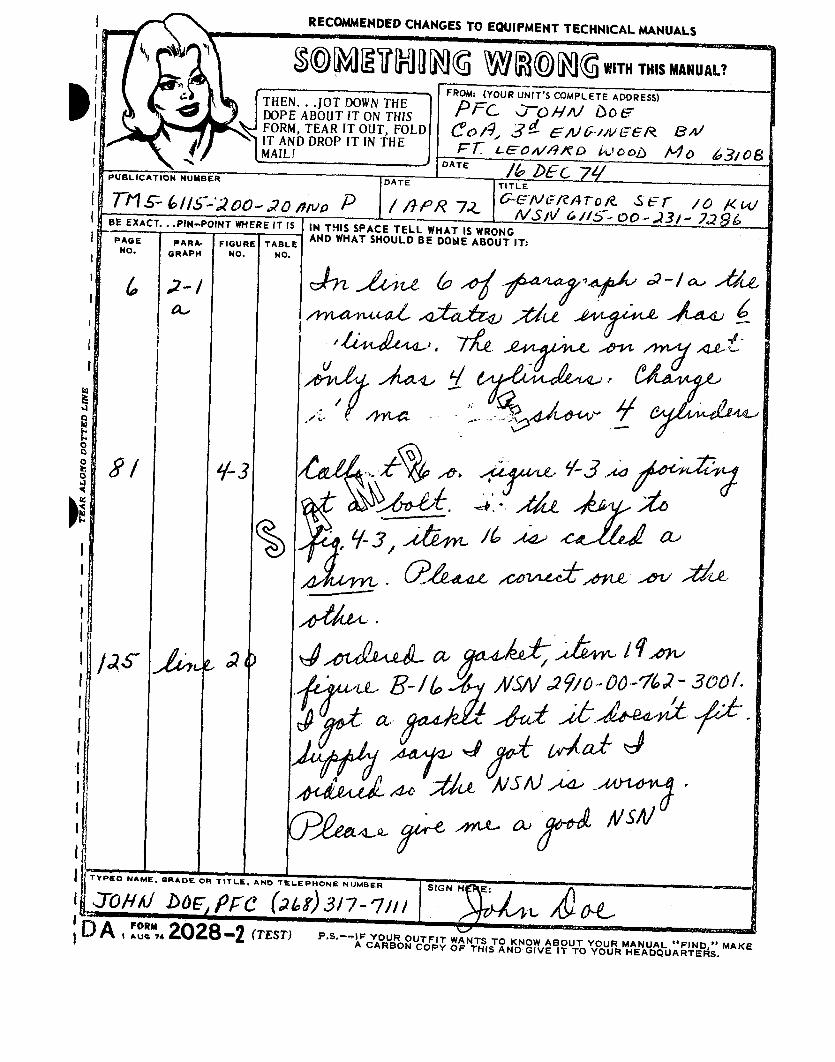

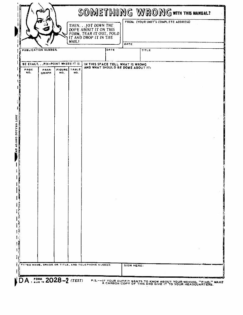


This fine document...
Was brought to you by me:
Liberated Manuals -- free army and government manuals
Why do I do it? I am tired of sleazy CD-ROM sellers, who take publicly available information, slap “watermarks” and other junk on it, and sell it. Those masters of search engine manipulation make sure that their sites that sell free information, come up first in search engines. They did not create it... They did not even scan it... Why should they get your money? Why are not letting you give those free manuals to your friends?
I am setting this document FREE. This document was made by the US Government and is NOT protected by Copyright. Feel free to share, republish, sell and so on.
I am not asking you for donations, fees or handouts. If you can, please provide a link to liberatedmanuals.com, so that free manuals come up first in search engines:
<A HREF=http://www.liberatedmanuals.com/>Free Military and Government Manuals</A>
– SincerelyIgor Chudovhttp://igor.chudov.com/
– Chicago Machinery Movers