Embed Size (px)
Citation preview

TRAINING GUIDE
GIS Analyst Tools for ArcGIS Desktop

GIS Analyst Tools for ArcGIS Desktop (2015 and 2015r2)
1
GIS Analyst Tools for ArcGIS Desktop
In this session, we’ll introduce you to the analyst tools that come with Lucity GIS for ArcGIS 10x.
Table of Contents
Summary of Lucity GIS Toolbar ......................................................................................... 3
Lucity Module Tool ........................................................................................................ 4
View Feature Relationships .......................................................................................... 5
Creating a Request ..................................................................................................... 5
Creating a Work Order or PM/Template ........................................................................... 7
Create Inspections ..................................................................................................... 9
Associate Document to Inspection ............................................................................. 10
View Associated Documents ........................................................................................ 11
Associate New Document ........................................................................................... 12
Filter Viewer ............................................................................................................. 13
Subsets .................................................................................................................... 15
Creating Inventory Subsets ......................................................................................... 15
Create an Inventory Subset (Ordered) ........................................................................... 16
Loading Inventory Subsets .......................................................................................... 17
Loading Address Subsets ............................................................................................ 18
Add to Existing Subset ............................................................................................... 19
Remove From an Existing Subset .................................................................................. 20
Work Frequency ......................................................................................................... 21
Add Assets from Map .................................................................................................... 23
Create Lucity Work Layers ............................................................................................. 24
Request Location ..................................................................................................... 25
Work Order Locations ............................................................................................... 28
Using the Work Order Location Tool .......................................................................... 31
Master Project Locations ........................................................................................... 32
View Routine/PM Locations ........................................................................................ 34
View Live Request Location Tool .................................................................................. 36
View Live Work Order Locations ................................................................................... 38
Lucity Views .............................................................................................................. 40
Recreating the View ................................................................................................. 40
View Descriptions .................................................................................................... 42
Profile View Tool ........................................................................................................ 45
Tab Options ........................................................................................................... 46
GIS Analyst Tools for ArcGIS Desktop (2015 and 2015r2)
2
View TV Observations ................................................................................................... 47
Trace Solver .............................................................................................................. 50
Tracing Water lines to Shut Off Points ........................................................................... 50
Tracing Sewer and Storm Lines .................................................................................... 51
Update Sign Regulations ............................................................................................... 53
Customer Search ......................................................................................................... 54
Find Feature .............................................................................................................. 55
Lucity Field Links ........................................................................................................ 56
Lucity Help ............................................................................................................... 57
Lucity GIS Settings ...................................................................................................... 57
Show in Map Option for Work Modules ........................................................................... 57
Symbology Defaults .................................................................................................. 58
Lucity Search Tolerance ............................................................................................ 59
Temporarily Change Search Tolerance........................................................................ 59
Set Default Search Tolerance ................................................................................... 59

GIS Analyst Tools for ArcGIS Desktop (2015 and 2015r2)
3
Summary of Lucity GIS Toolbar
The table below contains brief descriptions of the analyst tools available with Lucity GIS.
Button Name Description
Lucity Module View feature relationships; create inspections, requests, work orders, and PM/work templates; view/edit/attach documents
Filter Viewer View Lucity filters
Subset Manager Load, create, add to existing subsets, and remove from existing subsets
Work Frequency View work order frequency
Show in Map Interface Add assets and x/y coordinates to existing request, work
orders, and PM/work templates
Create Lucity Work Layers Tool to create both Live and Static views of Work Orders,
Requests, Master Projects, and PM/Templates.
Work Request Locations View locations of work requests, edit existing requests in a grid format, view work request location report, create work order(s) from selected request(s)
Work Order Locations View locations of work orders, edit existing work orders in a grid format, view work order location report
View Master Project Locations
View locations of Master Projects, view project conflicts
PM/WO Template Locations
View a select of locations for PM and Work Order Templates. From the locations users can view attribute information. This works exactly the same as the Work Order Locations Tool.
Lucity Views View inspection summaries and results for work, water,
street, storm, and sewer
Sewer/Storm Profile Creates a profile view for sewer or storm lines
View TV Observations Graphically displays TV observations for both sewer and storm
Trace Solver Traces sewer, storm, and water lines
Update Sign Regulations Assigns a group of signs to a specific CommonID
Customer Search Search customers by name or address, locate customer address in map, create requests, view customer information in Lucity
Find Feature Finds assets in the map based on the CommonID

GIS Analyst Tools for ArcGIS Desktop (2015 and 2015r2)
4
Field Links Allows you to join Lucity inventory information to a feature class.
Lucity Help A shortcut to the online Lucity GIS help manual was added.
All tools also have an F1 shortcut to the related help menu topic.
Lucity Module Tool The Lucity Module tool has seven options: View Feature Relationships, Create Requests, Create Work Orders, Create PM/Templates, Create Inspections, View Associated Document(s) and Associate New Document.
1. Select the Lucity Module tool from the Lucity toolbar.
2. In the map, right click on the feature with which you would like to work with.
Note: If you wish to work with multiple features, select the features in the map with the ESRI selection tool or the Lucity Module tool then using the Lucity Module tool right-click anywhere in the map.
3. A dialog box will appear.
4. Refer to the following sections for specific details on each of options
Notes: __________________________________________________________________________
_______________________________________________________________________________
_______________________________________________________________________________
_______________________________________________________________________________
_______________________________________________________________________________
_______________________________________________________________________________
_______________________________________________________________________________

GIS Analyst Tools for ArcGIS Desktop (2015 and 2015r2)
5
View Feature Relationships The View Feature Relationships option is used to view Lucity records related to the selected feature(s). When you select this option, a sub-menu will appear listing the features located within the search tolerance of the mouse-click. If there are any selected features in the map, there will also be an item in the list for all selected features.
1. Select the item in the submenu you wish to view relationships for. Once you select the item a dockable window will appear. By default, this window will be docked to the right of the ArcMap window.
o The window displays a list of related modules based upon the type of asset chosen. Next to the module description is the number of related records in parenthesis. Modules that have related records will be listed in bold.
2. Select the module in the dockable window you wish to open then click the Open Module in Lucity Desktop or Open Module in Lucity Web button at the top of the dockable window.
3. Lucity will open up to the related record(s).
Creating a Request The Create Requests option is used to create Lucity request records related to the selected feature(s). When you select this option the following sub-menu will appear:
X/Y: This option allows you to create a request with the X/Y coordinate where you clicked or against a single asset plus the X/Y coordinate.
For a Single Asset: This option will allow you to create a request for an asset located within the search tolerance of the right-click location.
For Each Asset: This option will allow you to create a separate request for each of the selected assets.

GIS Analyst Tools for ArcGIS Desktop (2015 and 2015r2)
6
1. After selecting the desired option a grid will appear. By default this grid contains the required fields for the request. This includes both fields required by Lucity and fields set required by users (via ctrl + right-click>>Field Properties in the desktop application). Populate the fields in the grid.
Additional fields can be configured so they also appear in the grid. Each row in the grid represents a separate work request record. Therefore, you will only have one row in the grid unless you choose an option to create multiple requests. Refer to the Default Fields Setup tool available on the Lucity Toolbar in ArcCatalog for more information.
It is strongly recommended that you populate the CategoryCode column first. This is due to the fact that other columns may populate automatically based upon the category chosen.
To assign the same value to multiple rows, select the desired rows by holding down the Shift or Ctrl key, then while still holding the Shift or Ctrl key click in the field to update and set the value. Once the cell you updated loses focus the grid will be refreshed to show the updated values.
Work flow setup columns will be followed by a button. Clicking the button will open a separate form which will let you select the appropriate item based upon the category. If you have permissions the Show All button will be enabled allowing you to toggle between seeing just the items associated to the category or all items in the system.
Note: The grid automatically detects data type errors once the cell loses focus. If the value you entered is not valid. You will receive a message similar to the following:
2. When you have finished filling out all of the required fields, submit your request. You have several submission options:
Submit and View in Desktop: This option will submit the request and automatically open them up in desktop application. The first record will be opened in edit mode.
Submit and View in the Web: This option will submit the request and automatically open them up in the Web application.
Submit Only: This option will submit the request, but Lucity will not be opened. You will stay in ArcMap.
Cancel: This will cancel the request and it will not be saved.

GIS Analyst Tools for ArcGIS Desktop (2015 and 2015r2)
7
Creating a Work Order or PM/Template Note: The process to create a PM/Work Template record is the same as the process to create Work Orders. The following steps are outlined for creating a work order, but can also be used to create a PM/work template.
The Create Work Orders option is used to create Lucity work order records related to the selected feature(s). When you select this option the following sub-menu will appear:
X/Y: This option allows you to create a work order with the X/Y coordinate where you clicked or against a single asset plus the X/Y coordinate.
For a Single Asset: This option will allow you to create a work order for an asset located within the search tolerance of the right-click location.
For All Assets: This option will allow you to create a SINGLE work order for all of the assets selected. This includes multiple asset types.
For Each Asset: This option will allow you to create a separate work order for each of the selected assets. This includes multiple asset types.
Note: If you choose the "For all selected features in map" option a dialog will appear prompting you to select a category for each particular asset type. This is required in order to properly populate the category associated with each asset selected.
The Select button is only enabled if you select a valid category.

GIS Analyst Tools for ArcGIS Desktop (2015 and 2015r2)
8
1. After selecting the desired option a grid will appear. By default this grid contains the required fields for the work order. This includes both fields required by Lucity application and fields set required by users (via ctrl + right-click>>Field Properties in the desktop application). Populate the fields in the grid.
o Additional fields can be configured so they also appear in the grid. Each row in the grid represents a separate work order record. Therefore, you will only have one row in the grid unless you choose an option to create multiple work orders. Refer to the Default Fields Setup tool available on the Lucity toolbar in ArcCatalog for more information.
o It is strongly recommended that you populate the CategoryCode column first. This is due to the fact that other columns may populate automatically based upon the category chosen.
o To assign the same value to multiple rows, select the desired rows by holding down the Shift or Ctrl key, then while still holding the Shift or Ctrl key click in the field to update and set the value. Once the cell you updated loses focus the grid will be refreshed to show the updated values.
o Work flow setup columns will be followed by a button. Clicking the button will open a separate form which will let you select the appropriate item based upon the category. If you have permissions the Show All button will be enabled allowing you to toggle between seeing just the items associated to the category or all items in the system.
Note: The grid automatically detects data type errors once the cell loses focus. If the value you entered is not valid. You will receive a message similar to the following:
2. When you have finished filling out all of the required fields, submit your work order. You have several submission options:
o Submit and View in Desktop: This option will submit the work order and automatically open them up in desktop application. The first record will be opened in edit mode.
o Submit and View in the Web: This option will submit the work order and automatically open them up in the Web application.
o Submit Only: This option will submit the work order, but Lucity will not be opened. You will stay in ArcMap.
o Cancel: This will cancel the work order and it will not be saved.

GIS Analyst Tools for ArcGIS Desktop (2015 and 2015r2)
9
Create Inspections The Create Inspections option is used to create Lucity inspection records related to the selected feature(s), as well as attach documents to the inspection records. When you select this option the following sub-menu will appear:
For a Single Asset: This option will allow you to create an inspection against an asset located within the search tolerance of the right-click location.
For All Assets: This option will allow you to create a separate inspection for each of the selected assets.
1. After selecting an option a form similar to the following will appear:
2. Select the type of inspection you wish to create and select an inspection date.
o The list of inspection types is based upon the asset type of the feature. Some asset types will have multiple inspection types, while others only have one. There are a few asset types that don't have an inspection module. In those cases you will receive the following prompt:
3. Once you select the type of inspection, inspection date, and click Submit a grid similar to the following will appear. By default this grid contains the required fields for the inspection. This includes both fields required by Lucity and fields set required by users (via ctrl + right-click>>Field Properties in the desktop application). Populate the fields in the grid.

GIS Analyst Tools for ArcGIS Desktop (2015 and 2015r2)
10
o Additional fields can be configured so they also appear in the grid. Each row in the grid represents a separate inspection record. Therefore, you will only have one row in the grid unless you choose an option to create multiple inspections. Refer to the Default Fields Setup tool available on the Lucity Toolbar in ArcCatalog for more information.
o To assign the same value to multiple rows, select the desired rows by holding down the Shift or Ctrl key, then while still holding the Shift or Ctrl key click in the field to update and set the value. Once the cell you updated loses focus the grid will be refreshed to show the updated values.
Note: The grid automatically detects data type errors once the cell loses focus. If the value you entered is not valid. You will receive a message similar to the following:
4. After filling out the required information you have four options: Submit and View in Desktop, Submit and View in Web, Submit Only, and Cancel.
o Submit and View in Desktop- This option will save inspection(s) to the database. It will then launch the desktop application and open the record in edit mode. If you choose an option that created multiple records then the inspection module will open in view mode with a filtered record set of the newly created records.
o Submit and View in Web- Opens the default web page.
o Submit Only- This option will save the inspection to the database and then close the form. You will receive a prompt similar to the following letting you know the item was successfully saved:
o Cancel- This option will cancel the inspection. Nothing will be saved to the database.
Associate Document to Inspection 1. To associate a document to the inspection you need to click the button in the associated
document column. The following window will appear:
2. Type or browse to the document location and enter a description, then click Attach.
Note: Check the option "This is a website or hyperlink" and type in the web address in the document location section.

GIS Analyst Tools for ArcGIS Desktop (2015 and 2015r2)
11
View Associated Documents The View Associated Document(s) option is used to view the files associated to the Lucity record. In addition, you can modify or delete associated documents. When you select this option the following sub-menu will appear.
1. Click on the desired asset and the Associated Documents window will appear.
2. All modules related to the feature will appear in the list on the left. Following the module description will be the number of associated documents in parenthesis. Selecting a module will update the grid to the right that lists the associated documents.
3. To view a document, simply double-click it and a separate window will open with the associated document.
Additional functionality is available by right-clicking in the grid. The following submenu would appear:
Selecting Edit allows you to modify the description and location of the document
Selecting Delete will remove the association. Note: this does not delete the actual file.

GIS Analyst Tools for ArcGIS Desktop (2015 and 2015r2)
12
Associate New Document The Associate New Document option is used to link an existing document to the Lucity asset record. When you select this option the following sub-menu will appear.
1. After you selected the desired option the Select Document to Associate dialog will appear. This allows you to browse to the document or enter in a website or hyperlink. You must also fill out the document description as this is required.
2. Once you have entered in the appropriate information, click Attach.
Notes: __________________________________________________________________
________________________________________________________________________
________________________________________________________________________
________________________________________________________________________
________________________________________________________________________

GIS Analyst Tools for ArcGIS Desktop (2015 and 2015r2)
13
Filter Viewer The Filter Viewer tool allows you to view filters that were saved in the Lucity desktop application.
1. Select the Filter Viewer tool . The Filter Viewer form will appear:
2. Select the module type that contains the filter you wish to display.
3. If in the previous step the module selection was: Asset Inventory, Asset Inspection/Testing then you will need to specify the asset type:
4. If the module selection was Asset Inspection/Testing you must specify the Inspection/Testing module based upon the asset type you previously selected.
GIS Analyst Tools for ArcGIS Desktop (2015 and 2015r2)
14
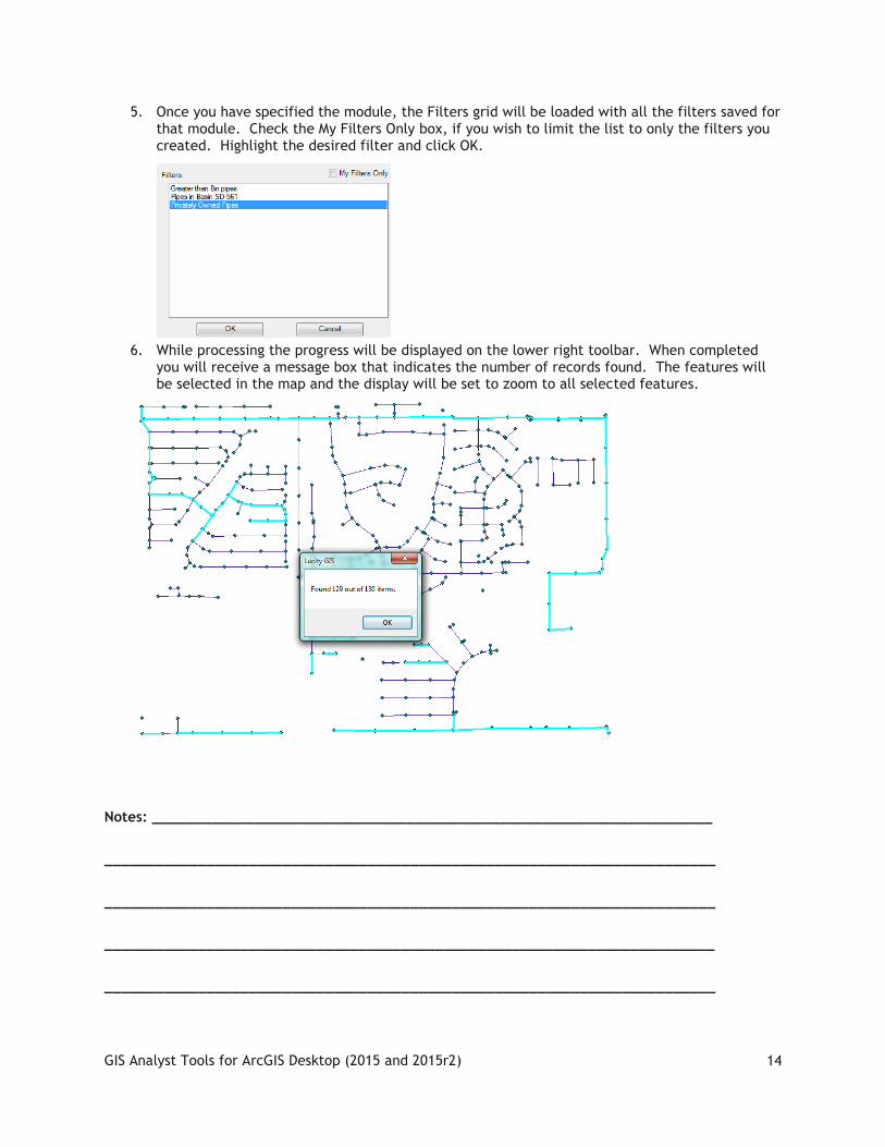
5. Once you have specified the module, the Filters grid will be loaded with all the filters saved for that module. Check the My Filters Only box, if you wish to limit the list to only the filters you created. Highlight the desired filter and click OK.
6. While processing the progress will be displayed on the lower right toolbar. When completed you will receive a message box that indicates the number of records found. The features will be selected in the map and the display will be set to zoom to all selected features.
Notes: __________________________________________________________________
________________________________________________________________________
________________________________________________________________________
________________________________________________________________________
________________________________________________________________________

GIS Analyst Tools for ArcGIS Desktop (2015 and 2015r2)
15
Subsets Subsets may be created and loaded in both Lucity™ and GIS. The Subset Manager allows you to save a group of filtered records from one module as a subset that can be viewed in related modules. For example, if you create a subset in the Sewer Television Inspection module of all pipes inspected prior to November 20, 2002, the subset can be viewed in both Television Inspection and Pipe Inventory because the subset contains information pertaining to both modules.
Creating Inventory Subsets 1. Using the ESRI selection tool, select the assets you would like to include in the subset.
2. Select the Subset tool . The Subset Manager form will appear:
3. Choose the infrastructure type from the drop down list and click Create. Note: Only infrastructure types that are currently in the map will appear in the list.
4. The Subset Manager form will expand showing a list of existing subsets and confirming the total number of features that will be included in the subset. Next, you’ll need to enter a unique subset name and click OK.
GIS Analyst Tools for ArcGIS Desktop (2015 and 2015r2)
16
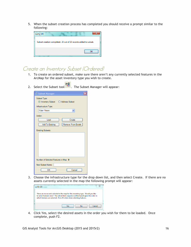
5. When the subset creation process has completed you should receive a prompt similar to the following:
Create an Inventory Subset (Ordered) 1. To create an ordered subset, make sure there aren’t any currently selected features in the
ArcMap for the asset inventory type you wish to create.
2. Select the Subset tool . The Subset Manager will appear:
3. Choose the infrastructure type for the drop down list, and then select Create. If there are no assets currently selected in the map the following prompt will appear:
4. Click Yes, select the desired assets in the order you wish for them to be loaded. Once complete, push F2.

GIS Analyst Tools for ArcGIS Desktop (2015 and 2015r2)
17
Loading Inventory Subsets
1. To load an inventory subset, select the Subset tool . The Subset Manager will appear:
2. Choose the infrastructure type from the drop down list and click Load.
Note: Only infrastructure types that are currently in the map will appear in the list.
3. The Subset Manager form will expand showing a list of existing subsets. Next, select a subset from the list and click OK.
4. Once the loading process has finished you'll receive a dialog similar to the following indicating the number of features found. Click Ok. The map will then highlight and zoom to the selected features.

GIS Analyst Tools for ArcGIS Desktop (2015 and 2015r2)
18
Loading Address Subsets
1. To load an address subset, select the Subset tool . The Subset Manager will appear:
2. Select the Address Subset option
3. The Subset Manager form will expand showing a list of existing subsets. Next, select a subset from the list and click OK.
4. Once the loading process has finished you'll receive a dialog similar to the following indicating the number of addresses found. Click Ok. The map will then highlight and zoom to the selected addresses.
GIS Analyst Tools for ArcGIS Desktop (2015 and 2015r2)
19
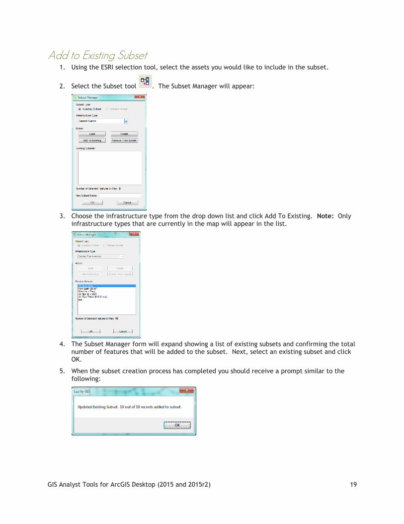
Add to Existing Subset 1. Using the ESRI selection tool, select the assets you would like to include in the subset.
2. Select the Subset tool . The Subset Manager will appear:
3. Choose the infrastructure type from the drop down list and click Add To Existing. Note: Only infrastructure types that are currently in the map will appear in the list.
4. The Subset Manager form will expand showing a list of existing subsets and confirming the total number of features that will be added to the subset. Next, select an existing subset and click OK.
5. When the subset creation process has completed you should receive a prompt similar to the following:

GIS Analyst Tools for ArcGIS Desktop (2015 and 2015r2)
20
Remove From an Existing Subset 1. Using the ESRI selection tool, select the assets you would like to remove from an existing
subset.
2. Select the Subset tool . The Subset Manager will appear:
3. Choose the infrastructure type from the drop down list and click Remove From Existing. Note: Only infrastructure types that are currently in the map will appear in the list.
4. The Subset Manager form will expand showing a list of existing subsets and confirming the total number of features that will be removed from the subset. Next, select an existing subset and click OK.
5. When the subset creation process has completed you should receive a prompt similar to the following:
GIS Analyst Tools for ArcGIS Desktop (2015 and 2015r2)
21
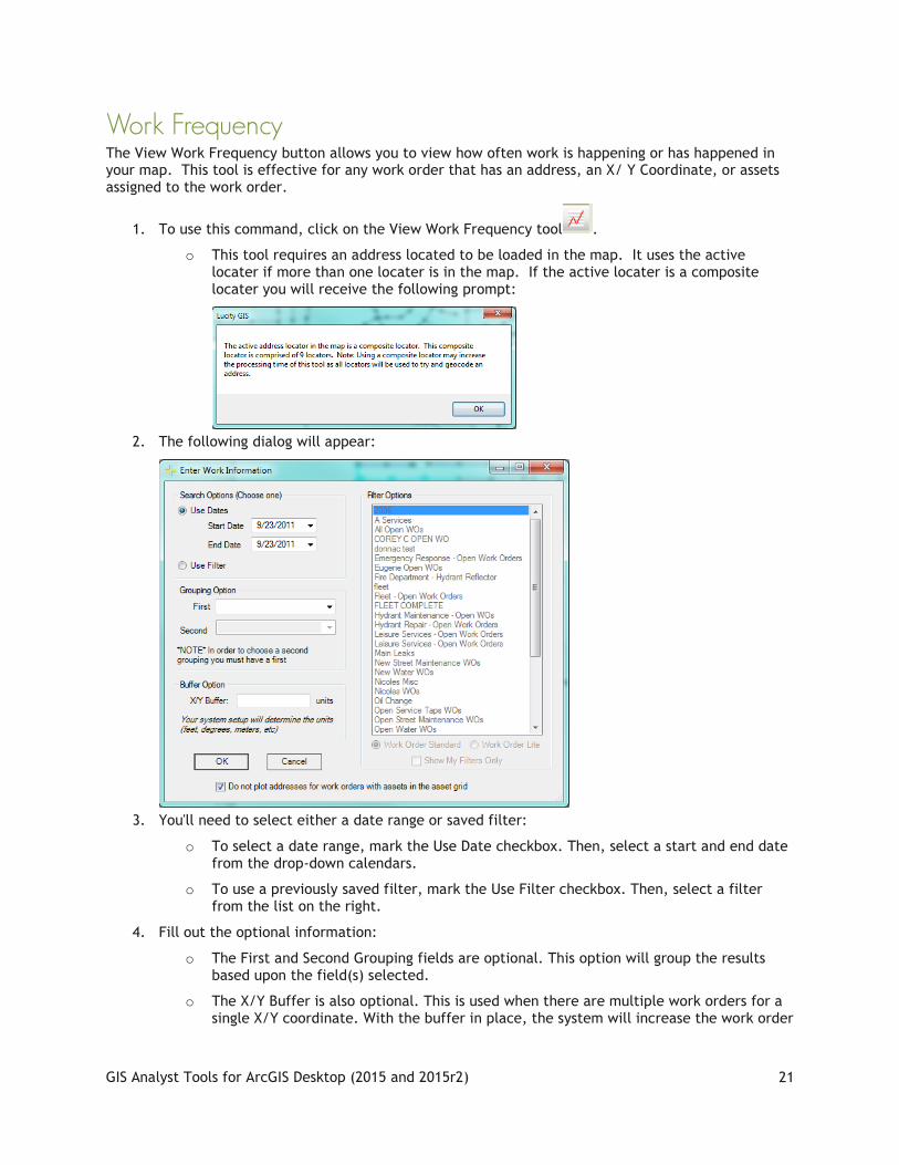
Work Frequency The View Work Frequency button allows you to view how often work is happening or has happened in your map. This tool is effective for any work order that has an address, an X/ Y Coordinate, or assets assigned to the work order.
1. To use this command, click on the View Work Frequency tool .
o This tool requires an address located to be loaded in the map. It uses the active locater if more than one locater is in the map. If the active locater is a composite locater you will receive the following prompt:
2. The following dialog will appear:
3. You'll need to select either a date range or saved filter:
o To select a date range, mark the Use Date checkbox. Then, select a start and end date from the drop-down calendars.
o To use a previously saved filter, mark the Use Filter checkbox. Then, select a filter from the list on the right.
4. Fill out the optional information:
o The First and Second Grouping fields are optional. This option will group the results based upon the field(s) selected.
o The X/Y Buffer is also optional. This is used when there are multiple work orders for a single X/Y coordinate. With the buffer in place, the system will increase the work order

GIS Analyst Tools for ArcGIS Desktop (2015 and 2015r2)
22
frequency instead of drawing additional points at the same X/Y coordinate. You system setup will determine the units you enter. These may be feet, degrees, meters, etc.
o By default the "Do not plot addresses for work orders with assets in the asset grid" is checked. If you uncheck this box then results will contain the locations of both the assets and potentially the address of the asset.
5. Click OK and the system will display the work order frequency that meets your selected criteria. While the system is processing, there will be a progress bar in the lower left-hand corner of the map.
6. Once the processing is finished, a grouped layer will be added to ArcMap containing three layers. The table of contents will show work order frequency for point, line, polygon features. The symbology for these layers has graduated sizing and color based on frequency. To change the way the frequency is displayed, right click on the layer and go to the symbology tab.
Note: In some cases, the tool may have been unable to map the location of a work order. You can determine whether a feature was found in the map by viewing the InMap field in the attribute table. A value of 1 indicates the feature was found, a value of 0 if it was unable to be located in the map.
GIS Analyst Tools for ArcGIS Desktop (2015 and 2015r2)
23
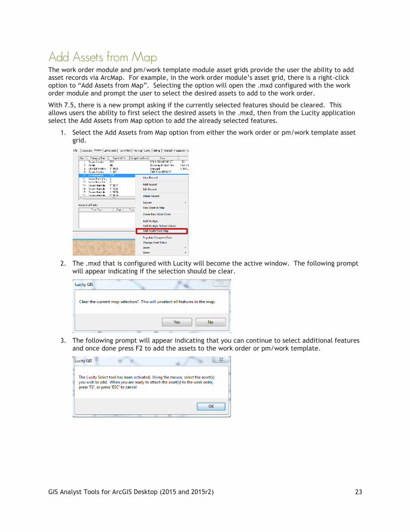
Add Assets from Map The work order module and pm/work template module asset grids provide the user the ability to add asset records via ArcMap. For example, in the work order module’s asset grid, there is a right-click option to “Add Assets from Map”. Selecting the option will open the .mxd configured with the work order module and prompt the user to select the desired assets to add to the work order.
With 7.5, there is a new prompt asking if the currently selected features should be cleared. This allows users the ability to first select the desired assets in the .mxd, then from the Lucity application select the Add Assets from Map option to add the already selected features.
1. Select the Add Assets from Map option from either the work order or pm/work template asset grid.
2. The .mxd that is configured with Lucity will become the active window. The following prompt will appear indicating if the selection should be clear.
3. The following prompt will appear indicating that you can continue to select additional features and once done press F2 to add the assets to the work order or pm/work template.

GIS Analyst Tools for ArcGIS Desktop (2015 and 2015r2)
24
Create Lucity Work Layers The Create Lucity Work Layers allows users to create special layers within the map that display information about Work Orders, Work Requests, Master Projects, and PM/Templates. This tool launches the various Work Location tools allowing users to create layers of work locations. After a work location layer is added to the map the individual tools also used to interact with the layers. This tool allows users to continue to add additional work location layers to the map
1. Click on the button in the toolbar. The following pop-up will appear:
2. Select the type of work location you would like to create from the drop down list and Click OK.
3. The associated tool will appear allowing you to provide further details specific to the type of work.
Notes: __________________________________________________________________
________________________________________________________________________
________________________________________________________________________
________________________________________________________________________
________________________________________________________________________

GIS Analyst Tools for ArcGIS Desktop (2015 and 2015r2)
25
Request Location The View Work Request Locations tool allows you to view work request locations in ArcMap. Once the work request locations have been added to the map the tool also offers the ability to view and edit work requests and view a work request report. This tool is effective for any request that has an address, an X/Y, or assets assigned to the work request.
1. To use this command, click on the View Work Request
Locations tool . You will be prompted with a dialog asking which requests you would like to view.
2. Choose a search option
o Date and Category(ies) - This option will search for all work requests where the work request category is in the list specified and the work request start date is between the dates specified.
o Work Request Filter- This option will search for all work requests that meet the filter criteria specified.
o Work Request Filter and Dates- This option will search for all work requests that meet the criteria specified in the filter AND has a work request start date between the dates specified.
3. Depending on what option you choose the form will expand and display either a list of categories or a list of filters. Select the desired category or filter.
o If you would like to view work requests from one category only, you can open the category tree on the right hand side and select a category you are interested in. Selecting a category will only show work orders assigned to that specific category, not all categories beneath that category.
o If you prefer not to select a specific category, you can check the "All Categories" checkbox (Hint: If you do not select a category, the system automatically queries all categories, so it is not required that you check this box).
4. Select a spatial filter option (Optional)
o Use the current map extent- This option will filter the results down so only request locations that are in the current map extent will be included in the results

GIS Analyst Tools for ArcGIS Desktop (2015 and 2015r2)
26
o Select polygon features- This option will limit the results down to only show request locations that intersect selected polygon features. If you select this option the following dialog will appear once you select Display
5. Modify default fields in the results option (Optional).
o By default there are certain fields that this tool will add to the results. By checking this option you will have the ability to customize what fields are included in the results. The form will expand exposing the following items:
o Place a check next to the fields you wish to have added to the results.
o Fields that are automatically added by the tool are shown in the list to the far right. Users are unable to modify this list as these are required for the functionality of the tool.
o Users have the ability to save the custom field option by clicking the "Save as new user default" button. This setting is saved to the database, and these fields will automatically be checked the next time the user runs the tool.
6. When ready to process click "Display". If there are a significant number of work requests to process a dialog similar to this will appear:

GIS Analyst Tools for ArcGIS Desktop (2015 and 2015r2)
27
7. Once the processing is finished a grouped layer will be added to ArcMap containing three layers (point, line, and polygon). To change the way the layers are displayed, right click on the layer and go to the symbology tab.
o The search criteria used for the work request is listed in the description for the group layer. To access this information, right-click on the grouped layer and select Properties. You will see a screen similar to this.
8. The tool will attempt to map all work request locations for all work requests that meet your selected criteria. Features that weren't able to be spatially represented will still be added to the layer, but will have a value of 0 in the FoundInMap field in the attribute table for the feature class.
9. After the request locations have been added to the map the cursor will change to crosshairs and you can then right-click on features to either view the requests in the desktop, edit work orders directly in ArcMap, or to view/print the request report.
Notes: __________________________________________________________________________
_______________________________________________________________________________
_______________________________________________________________________________
_______________________________________________________________________________
_______________________________________________________________________________

GIS Analyst Tools for ArcGIS Desktop (2015 and 2015r2)
28
Work Order Locations The View Work Locations tool allows you to view work order locations in ArcMap. Once the work order locations have been added to the map the tool also offers the ability to view and edit work orders and view a work order report. This tool is effective for any work order that has an address, an X/Y Coordinate (location tab in work orders), or assets assigned to the work order (asset tab in work orders.
1. To use this command, click on the View Work Locations
tool . You will be prompted with a dialog asking which work orders you would like to view.
2. Choose a search option
o Date and Category(ies)- This option will search for all work orders where the work order category is in the list specified and the work order start date is between the dates specified.
o Work Order Filter- This option will search for all work orders that meet the filter criteria specified.
o Work Order Filter and Dates- This option will search for all work orders that meet the criteria specified in the filter AND has a work order start date between the dates specified.
3. Depending on what option you choose the form will expand and display either a list of categories or a list of filters. Select the desired category or filter.
o If you would like to view work from one category only, you can open the category tree on the right hand side and select a category you are interested in. For the current version of the software, selecting a category will only show work orders assigned to that specific category, not all categories beneath that category.
o If you prefer not to select a specific category, you can check the "All Categories" checkbox (Hint: If you do not select a category, the system automatically queries all categories, so it is not required that you check this box).
o For filters, the default is to show My Filters Only. You have the option to uncheck this and use any filter
4. Spatial Filter Option (Optional)
o Use the current map extent- This option will filter the results down so only work locations that are in the current map extent will be included in the results

GIS Analyst Tools for ArcGIS Desktop (2015 and 2015r2)
29
o Select polygon features- This option will limit the results down to only show work locations that intersect selected polygon features. If you select this option the following dialog will appear once you select Display
5. Modify default fields in the results (Optional).
o By default there are certain fields that this tool will add to the results. By checking this option you will have the ability to customize what fields are included in the results. The form will expand exposing the following items:
o Place a check next to the fields you wish to have added to the results.
o Fields that are automatically added by the tool are shown in the list to the far right. Users are unable to modify this list as these are required for the functionality of the tool.
o Users have the ability to save the custom field option by clicking the "Save as new user default" button. This setting is saved to the database, and these fields will automatically be checked the next time the user runs the tool.
6. When ready to process click "Display". If there are a significant number of work orders to process a dialog will appear:
7. Once the processing is finished a grouped layer will be added to ArcMap containing three layers (point, line, and polygon). To change the way the layers are displayed, right click on the layer and go to the symbology tab.

GIS Analyst Tools for ArcGIS Desktop (2015 and 2015r2)
30
o The search criteria used for the work orders is listed in the description for the group layer. To access this information, right-click on the grouped layer and select Properties.
8. The tool will attempt to map all work locations for all work orders that meet your selected criteria. Features that weren't able to be spatially represented will still be added to the layer, but will have a value of 0 in the FoundInMap field in the attribute table for the feature class.
9. After the work locations have been added to the map the cursor will change to crosshairs and you can then right-click on features to either view work orders in the desktop application, edit work orders directly in ArcMap, or to view/print the work order report. More information on these operations can be found in the Using the Work Order Location Tool section.

GIS Analyst Tools for ArcGIS Desktop (2015 and 2015r2)
31
Using the Work Order Location Tool
The View Work Locations tool allows you to view work order locations in ArcMap. Once the work order locations have been added to the map the tool also offers the ability to view and edit work orders and view a work order report. The following are instructions on using the tool once the work order layers have already been created and added to the map.
1. To use this tool, click on the View Work Locations tool . You will be prompted with a dialog asking which work orders you would like to view. If you have already used the tool to create the work order layers then you will receive the following prompt:
o If you wish to use the tool to create a new work order location layer, click Yes; otherwise, select No and you can use the tool to interact with the existing work order location layers.
2. While the View Work Locations tool is enabled, right-click on a work order’s location. A menu will appear providing you with three options: View Work Order(s), Edit Work Order(s), or View Work Order Report. Selecting the desired option will open a submenu that lists the work orders located within the search tolerance of the mouse-click.
o To perform an option on multiple work orders, use the View Work Locations tool to select the work orders prior to using the View Work Locations tool, then when you right-click you will have the "For all selected Work Orders" option added to the submenu list.
3. Select the work order from the list to perform the function
o View Work Orders: This option will open the selected work order(s) in the desktop in view mode.
o Edit Work Order(s): This will open the selected work order(s) in an editable grid within ArcMap. By default, all required fields are added to the grid. This includes both fields required by the desktop application and fields set required by users (via ctrl + right-click>>Field Properties in the desktop application).

GIS Analyst Tools for ArcGIS Desktop (2015 and 2015r2)
32
o View Work Order Report: This will open the Work Order Report that is provided as a default Lucity report. This tool will take a snapshot of the current ArcMap display and saves it as a .jpg which is used by the Work Order Report.
o Create Work Order(s) - Note: this is only available when using the Request Location Viewer tool. This will create a new work order(s) for the selected requests. Once compete the following dialog will appear with the options to view the newly created work order.
Master Project Locations The View Master Project Locations tool allows you to view master project locations in ArcMap. In addition it allows you to show any project conflicts. This tool is effective for any master project that has an address, an X/Y coordinate, or assets assigned to the master project.
1. To use this command, click on the View Master Projects Locations tool . You will be prompted with a dialog asking which master projects you would like to view.
GIS Analyst Tools for ArcGIS Desktop (2015 and 2015r2)
33
2. You are required to select a filter. Select a master project filter from the list.
3. Select additional fields (Optional). You can also choose additional fields that are not in the System Default Fields list. These fields will appear in the feature class results.
4. Project Conflicts (Optional) - Select this option if you wish to have an additional group layer in the results that display the locations where there are project conflicts. A conflict is any location in which more than one project resides.
5. You can also choose additional fields that are not in the System Default Fields list.
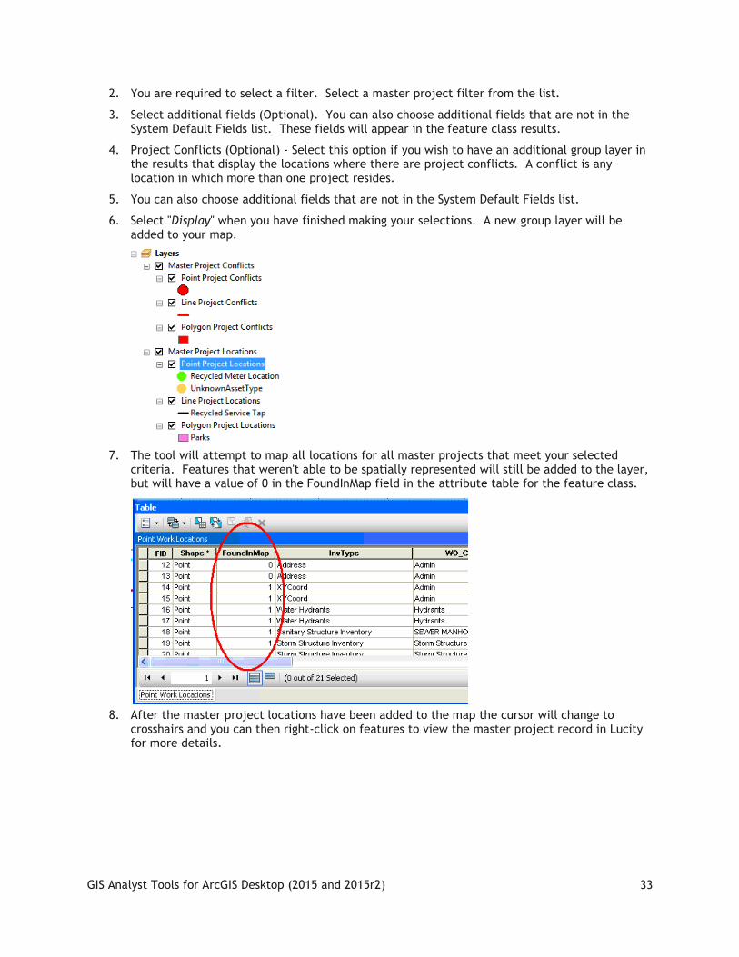
6. Select "Display" when you have finished making your selections. A new group layer will be added to your map.
7. The tool will attempt to map all locations for all master projects that meet your selected criteria. Features that weren't able to be spatially represented will still be added to the layer, but will have a value of 0 in the FoundInMap field in the attribute table for the feature class.
8. After the master project locations have been added to the map the cursor will change to crosshairs and you can then right-click on features to view the master project record in Lucity for more details.

GIS Analyst Tools for ArcGIS Desktop (2015 and 2015r2)
34
View Routine/PM Locations With 7.6 a new tool has been added to the View Work Locations suite. Similar to the other tools the View Routine/PM Locations tool will map the locations of routine/pm records based upon user specified search criteria.
1. To use the View Routine/PM locations tool, click . The following dialog will appear:
2. Choose a search option:
o Date and Category(ies) - This option will search for all PM records where the PM category is in the list specified and the next work order creation date is between the dates specified.
o PM/Work Template Filter- This option will search for all PM records that meet the filter criteria specified.
o PM/Work Template Filter and Dates- This option will search for all PM records that meet the criteria specified in the filter AND have a PM start date between the dates specified.
Note: Regardless of your option the results will always end up being filtered on either the next start date or next end date as shown above.
3. Depending on the option that is chosen the form will expand and display either a list of categories or a list of filters. Select the desired category or filter.

GIS Analyst Tools for ArcGIS Desktop (2015 and 2015r2)
35
4. Spatial Filter Option- This option allows users to specify a specific area to view PM records in.
o None- All PM records specified by the search criteria will be displayed.
o User the Current Map Extent- Only PM records within the location of the current extent will be displayed.
o Select Polygon Feature(s) - Allows users to select a polygon feature in the map. Only PM records that are found within that polygon feature will be displayed.
5. Modify default fields in the results option
o By default there are certain fields that will be included in the results. This option will allow users to include additional fields in the results.
6. When ready to process click the Display button.
7. Once the processing is finished a grouped layer will be added to ArcMap containing three layers (point, line, polygon).
o The search criteria used for the PM records is listed in the description for the group layer. To access this information, right-click on the grouped layer and select Properties.
8. The tool would have attempted to map all locations for each PM record in the search criteria. Features that weren’t able to be spatially represented will still be added to the layer, but will have a value of 0 in the FoundInMap field in the attribute table for the feature class.
9. After the locations have been added to the map the cursor will change to crosshairs and you can then right-click on the features to view the PM records in the desktop application.

GIS Analyst Tools for ArcGIS Desktop (2015 and 2015r2)
36
View Live Request Location Tool 1. Click the button in the toolbar. The following pop-up will appear:
2. Select Requests.
3. Click OK. The associated tool will appear.
OR
1. Click on the View Work Request Locations tool . The following pop-up will appear:
2. Select Requests.
3. Click OK. The associated tool will appear.
Note: This option will not work if there is already a request or request live layer in the map.
4. The tool allows users to filter down which requests to display.

GIS Analyst Tools for ArcGIS Desktop (2015 and 2015r2)
37
5. Choose a filtering option
Select an existing filter - This option allows the user to select a filter that was created and saved in the Request module.
Specify advanced filter - This option allows the user to write a filter using SQL.
No filter (load all records) - This option loads all request records that contain spatial data.
6. Depending on the chosen option the user should then
Select a filter from the list of filters. To display only your filters check the My Filters Only box.
Write a filter in the Manually enter WHERE clause box. Start this with WHERE...
7. Enable the time on the layers if desired and fill out the Time Step Interval.
8. By default the following options are checked.
Do not plot addresses for records with assets - When a request contains an asset and the address the tool will only plot the asset. Otherwise it would plot both.
Do not plot addresses for records with X/Y Coordinates - When a request contains an address and x/y coordinates the tool will only plot the x/y coordinates. Otherwise it would plot both.
9. By default there are certain fields that this tool will add to the results. Checking the Select which fields should be included in the resulting layer(s) box will allow users to customize what fields are included in the results. The form will expand exposing the following items:
Place a check next to the fields to have added to the results.
Fields that are automatically added by the tool are shown in the list to the far right. Users are unable to modify this list as these are required for the functionality of the tool.
Users have the ability to save the custom field option by clicking the Save as new user default button. This setting is saved to the database, and these fields will automatically be checked the next time the user runs the tool.
10. When ready to process click Display.

GIS Analyst Tools for ArcGIS Desktop (2015 and 2015r2)
38
View Live Work Order Locations 1. Click the button in the toolbar. The following pop-up will appear:
2. Select Work Orders.
3. Click OK. The associated tool will appear.
OR
1. Click on the View Work Order Locations tool . The following pop-up will appear:
2. Select Work Orders (Live).
3. Click OK. The associated tool will appear.
Note: This option will not work if there is already a work or work live layer in the map.
4. The tool allows users to filter down which work orders to display.

GIS Analyst Tools for ArcGIS Desktop (2015 and 2015r2)
39
5. Choose a filtering option
Select an existing filter - This option allows the user to select a filter that was created and saved in the Work Order module.
Specify advanced filter - This option allows the user to write a filter using SQL.
No filter (load all records) - This option loads all work order records that contain spatial data.
6. Depending on the chosen option the user should then
Select a filter from the list of filters. To display only your filters check the My Filters Only box.
Write a filter in the Manually enter WHERE clause box. Start this with WHERE...
7. Enable the time on the layers if desired and fill out the Time Step Interval.
8. By default the following options are checked.
Do not plot addresses for records with assets - When a work order contains an asset and the address the tool will only plot the asset. Otherwise it would plot both.
Do not plot addresses for records with X/Y Coordinates - When a work order contains an address and x/y coordinates the tool will only plot the x/y coordinates. Otherwise it would plot both.
9. By default there are certain fields that this tool will add to the results. Checking the Select which fields should be included in the resulting layer(s) box will allow users to customize what fields are included in the results. The form will expand exposing the following items:
Place a check next to the fields to have added to the results.
Fields that are automatically added by the tool are shown in the list to the far right. Users are unable to modify this list as these are required for the functionality of the tool.
Users have the ability to save the custom field option by clicking the Save as new user default button. This setting is saved to the database, and these fields will automatically be checked the next time the user runs the tool.
10. When ready to process click Display.

GIS Analyst Tools for ArcGIS Desktop (2015 and 2015r2)
40
Lucity Views To view the summary or results data produced by any one of the Lucity Views tools, complete the following steps:
1. Expand the Lucity Views drop-down list in the Lucity GIS toolbar and select the tool you’d wish to use.
2. The length of time each tool takes to run depends on the number of records you have in the Lucity database. A progress bar located in the bottom left-hand corner of the ArcMap window will show the status of the tool.
3. When completed, an additional instance of the feature layer will be added to the map. The instance will have an alias name identifying the tool that you used.
Recreating the View Each time a view tool is used, the tool determines if the view already exists in the database, if so, it simply uses the existing view. If the view doesn’t exist the tool will create the view automatically with the default settings.
There may be situations where you would like to recreate the view. When you recreate the view you will have the option to apply additional filter criteria to the view to limit the results. This greatly improves performance with large datasets.
1. Expand the Lucity Views drop-down list in the Lucity GIS toolbar and select the tool you’d wish to use while pressing the SHIFT key.
2. The following message will appear confirming that you wish to recreate the view. Click Yes.

GIS Analyst Tools for ArcGIS Desktop (2015 and 2015r2)
41
3. The Create View Options dialog will appear.
4. Select the additional criteria option:
o None: This is the default. This will create the view with the default syntax that is listed under the View syntax window.
o Inventory Filter: Select this option if you wish to limit the view so only the records that meet the criteria listed in an inventory filter will be included in the results.
o Inspection Filter: Select this option if you wish to limit the view so only the records that meet the criteria listed in an inspection filter will be included in the results.
5. Fill out a layer description (optional). Enter the text you want displayed with the layer’s description property.
6. Select a filter. If you chose either the Inventory or Inspection Filter option you must select which filter you want to apply to the results.
7. To create the view, click OK.
Note:___________________________________________________________________________
_______________________________________________________________________________
_______________________________________________________________________________
_______________________________________________________________________________
_______________________________________________________________________________
_______________________________________________________________________________

GIS Analyst Tools for ArcGIS Desktop (2015 and 2015r2)
42
View Descriptions Tool Operation
Sewer
View Manhole Inspection Results
Graphically displays your latest manhole inspection information as another instance of your sewer structure feature class. This instance will have the latest structure inspection information for each structure joined to the attribute table. The symbology for the layer is based on the total structural number (MH_SUM_STR) of the inspection. Manholes with a lower structural number will appear yellow; manholes with a higher structural number will appear red.
View TV Inspection Summary
Graphically displays your latest TV inspection information as another instance of your sewer pipe feature class. This instance will have the latest TV inspection information for each pipe joined to the attribute table. The symbology for the layer is based on the total structural number (TL_STR_TOT) of the inspection. Pipes with a lower structural number will appear yellow; pipes with a higher structural number will appear red.
View PACP Inspection Summary
Graphically displays your latest PACP inspection information as another instance of your sewer pipe feature class. This instance will have the latest PACP inspection information for each pipe joined to the attribute table. The symbology for the layer is based on the total pipe rating (PA_PRT) of the inspection. Pipes with a lower structural number will appear yellow; pipes with a higher structural number will appear red.
View Lamping Inspection Results
Graphically displays your latest lamping inspection results as two additional instances of your sewer pipe feature class. One instance will be for lamping inspections from the downstream structure, the other for inspections from the upstream structure. These added layers will have the latest lamping inspection information for each pipe joined to the attribute table. The symbology for the layers is based on the total structural number (LP_TOT_STR) of the inspection. Pipes with a lower structural number will appear yellow; pipes with a higher structural number will appear red.
View Smoke Inspection Summary
Graphically displays your latest smoke test inspection information as another instance of your sewer pipe feature class. This instance will have the latest smoke test inspection information for each pipe joined to the attribute table. The symbology for the layer is based on the result text (SM_RSLT_TY) of the inspection.
View Sewer Rehab Results
Graphically displays your sewer rehab results as another instance of your sewer pipe feature class. This instance will have the latest Pipe Analysis Details for each pipe joined in the attribute table.
Note:___________________________________________________________________________
_______________________________________________________________________________
_______________________________________________________________________________
_______________________________________________________________________________
_______________________________________________________________________________

GIS Analyst Tools for ArcGIS Desktop (2015 and 2015r2)
43
Storm
View Structure Inspection Results
Graphically displays your latest structure inspection information as another instance of your storm structure feature class. This instance will have the latest structure inspection information for each structure joined to the attribute table. The symbology for the layer is based on the total structural number (SI_STR_TOT) of the inspection. Structures with a lower structural number will appear yellow; structures with a higher structural number will appear red.
View TV Inspection Summary
Graphically displays your latest TV inspection information as another instance of your storm conduit feature class. This instance will have the latest TV inspection information for each pipe joined to the attribute table. The symbology for the layer is based on the total structural number (CI_TOTSTRC) of the inspection. Pipes with a lower structural number will appear yellow; pipes with a higher structural number will appear red.
View Storm Sampling Results
Graphically displays your latest storm sampling result information as another instance of your storm structure feature class. This instance will have the latest storm sampling information for each structure joined to the attribute table. The symbology for the layer is based on the total PH count (SS_PH_D, SS_PH_U, SS_PH_A) of the inspection. The results will create a group layer with three feature classes. One representing the results of sampling results that were performed upstream from the structure, downstream from the structure and at the structure.
Street
View Street PCI Data Graphically displays your current PCI data as another instance of your street subsegment feature class. This instance will have the latest field inspection information for each subsegment joined to the attribute table. The symbology for the layer is based on the current PCI number (FD_CUR_PCI) of the inspection. Subsegments with a lower PCI will appear yellow; subsegments with a higher PCI will appear red.
View Street Modelling Results
Graphically displays your modelling results as another instance of your street subsegment feature class. This instance will have the selected model result details for each subsegment joined to the attribute table. The symbology for this layer is based on the Rehab Text of the model result.
View Street Pavement Maintenance
Graphically displays your current PCI data as another instance of your street subsegment feature class. This instance will have the latest pavement maintenance information for each subsegment joined to the attribute table. The symbology for the layer is based on the override PCI value (RB_OPCI) of the inspection. Subsegments with lower PCI will appear yellow; subsegments with a higher PCI will appear red.
View Road Pavement Maintenance
Graphically displays your current PCI data as another instance of your road segment feature class. This instance will have the latest pavement maintenance information for each road segment joined to the attribute table. The symbology for the layer is based on the override PCI value (RB_OPCI) of the inspection. Road segments with lower PCI will appear yellow; road segments with a higher PCI will appear red.

GIS Analyst Tools for ArcGIS Desktop (2015 and 2015r2)
44
Water
View Hydrant Flow Test Results
Graphically displays your latest hydrant flow test results as another instance of your hydrant feature class. This instance will have the latest hydrant flow test information for the hydrant joined to the attribute table. The symbology for the layer is based on the flow at 20psi (HT_Q20) of the hydrant. Hydrants with a lower flow at 20psi will appear yellow; hydrants with a higher flow at 20psi will appear red.
View Test Dates for Backflow Devices
Graphically displays your next backflow device test dates as another instance of your backflow device feature class. This instance will have some inventory data for the backflow device joined to the attribute table. The symbology for the layer is based on the next test date (BF_NTST_DT) of the backflow device. Devices with an earlier next test date will appear yellow; devices with a later next test date will appear red.
View Meter Device and AMR Info
Graphically displays the water meter locations with all of the fields from the Water Meter Device and AMR modules. These fields are populated with information from the device and reader that are attached to the Water Meter Location.
Note:___________________________________________________________________________
_______________________________________________________________________________
_______________________________________________________________________________
_______________________________________________________________________________
_______________________________________________________________________________
_______________________________________________________________________________
_______________________________________________________________________________
_______________________________________________________________________________
_______________________________________________________________________________
_______________________________________________________________________________
_______________________________________________________________________________
_______________________________________________________________________________
_______________________________________________________________________________
_______________________________________________________________________________
_______________________________________________________________________________

GIS Analyst Tools for ArcGIS Desktop (2015 and 2015r2)
45
Profile View Tool The Profile tool allows users view a profile of a set of sewer pipes or storm conduits. This profile is based on the Rim Elevation, Structure Depth, Upstream and Downstream inverts fields from the Sewer Structure, Sewer Pipe, Storm Structure, and Storm Conduit modules. This information must be filled out correctly first, for the profile to appear correctly.
1. Make sure both the Sewer Structures and Sewer Pipes, or Storm Structures and Storm Conduits are in the map.
2. Select the tool from the Lucity GIS Analyst toolbar. The following popup will appear:
3. The cursor will turn into a cross hair. Click on the first pipe to be in the profile. The profile will go downstream from the pipe selected.
4. After selecting a pipe the following popup will appear:
5. Select how many pipes to include in the profile and click OK. The Profile will be created automatically.

GIS Analyst Tools for ArcGIS Desktop (2015 and 2015r2)
46
o Title- This indicates whether the trace was for sewer or storm
o Legend- Provides a reference of the symbology used in the profile
o Options- Each tab contains various options for the profile
o Summary- Provides an overall summary of the profile calculations.
In the profile window you can zoom in/out with the mouse. In addition, right-clicking on a feature will produce the following context menu allowing you to view that record in the Lucity application.
Tab Options o Layers: Controls layer visibility and symbology size.
o Labels: Controls visibility, placement, size, text, and color properties of the labels.
o 3D: Controls the options to display the profile in a 3D
o Print/Save: Provides options to prepare profile for printing and ability to save the profile as an image.
Note:___________________________________________________________________________
_______________________________________________________________________________
_______________________________________________________________________________
_______________________________________________________________________________
_______________________________________________________________________________
_______________________________________________________________________________
_______________________________________________________________________________

GIS Analyst Tools for ArcGIS Desktop (2015 and 2015r2)
47
View TV Observations TV Observation information can be displayed in ArcMap using the View TV Observations tool. This tool creates and displays a shapefile of TV Observation points along with providing functionality with the ESRI hyperlink tool to view any associated documents such as images or movies.
1. Click the View TV Observations tool in the Lucity GIS toolbar. The following dialog will appear:
2. Select an inspection type, specify a max inspection date, and select one of the following search criteria options:
o All Pipes/Conduits- Use this option to view the results for your entire sewer/storm pipe inventory
o Currently Selected Pipes in the Map- This option will only be enabled if you have multiple pipes selected in the map. Use this option to view the results for only the selected pipes.
o Inventory Filter- Use this option to view the results only for those pipes that meet the selected filter criteria.
o Inspection Filter- Use this option to view the results only for those pipes that meet the selected filter criteria.
Note:___________________________________________________________________________
_______________________________________________________________________________
_______________________________________________________________________________
_______________________________________________________________________________
GIS Analyst Tools for ArcGIS Desktop (2015 and 2015r2)
48
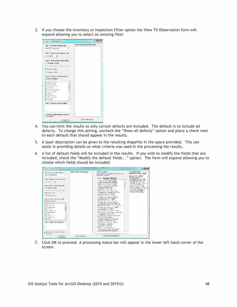
3. If you choose the Inventory or Inspection Filter option the View TV Observation form will expand allowing you to select an existing filter
4. You can limit the results so only certain defects are included. The default is to include all defects. To change this setting, uncheck the “Show all defects” option and place a check next to each default that should appear in the results.
5. A layer description can be given to the resulting shapefile in the space provided. This can assist in providing details on what criteria was used in the processing the results.
6. A list of default fields will be included in the results. If you wish to modify the fields that are included, check the “Modify the default fields...” option. The form will expand allowing you to choose which fields should be included.
7. Click OK to proceed. A processing status bar will appear in the lower left-hand corner of the screen.

GIS Analyst Tools for ArcGIS Desktop (2015 and 2015r2)
49
8. When processing is complete the shapefile will be added to the map. Observations are displayed in the map using a symbol placed along the pipe. The color of the symbol represents the type of defect; the size of the symbol corresponds to the severity or rating of the defect. A legend defining these symbols appears in the Table of Contents.
9. If any of the defects have associated images/documents the ESRI hyperlink tool will become enabled. You can use this tool to click on a defect location and the associated image/document will open directly from ArcMap.
Note: There is a field in the shapefile that indicates if there are any associated documents. This can assist you in using the ESRI hyperlink tool
Note:___________________________________________________________________________
_______________________________________________________________________________
_______________________________________________________________________________
_______________________________________________________________________________
_______________________________________________________________________________
_______________________________________________________________________________
_______________________________________________________________________________

GIS Analyst Tools for ArcGIS Desktop (2015 and 2015r2)
50
Trace Solver The Trace Solver includes tools for tracing sewer, storm, and water lines without an ArcInfo license or ArcGIS network developed. These tools do not use the Trace solvers that are built into ArcGIS and therefore run with ArcView license configurations.
Tracing Water lines to Shut Off Points 1. First Click on the Trace Solver Tool . The Following dialog will appear:
2. Select "Water Isolation Valve Trace" from the drop-down list and make the Trace Solver the active tool.
3. At this point you are given several options.
o Water Line Trace Options: Place a check next to the statuses that indicate a valve can NOT be closed. If you don't check any status then the tool will assume that all isolation valves can be turned off.
o Subset Option: When you check the option for subsets, the field to the right will be enabled for you to enter a subset name.

GIS Analyst Tools for ArcGIS Desktop (2015 and 2015r2)
51
o Hydrant Options: Selecting by pipe number assigned to the hydrant is the most accurate method of selecting hydrants affected by a shutoff. If this data is not available, you can have the system select all hydrants within a specified distance of the water mains.
4. Click Trace.
5. The mouse cursor will change to crosshairs which you then click a point along your water pipe feature class where you want the trace to begin. This will start the trace and when completed you will receive the following prompt and the map display will be refreshed to zoom to the extent of the selected water pipes.
6. You can continue to use the tool to perform additional traces by clicking on a point along your water pipe feature class.
Tracing Sewer and Storm Lines 1. First Click on the Trace Solver Tool . The Following dialog will appear:
2. Select a trace from the drop down box:
3. The available traces are described below:
GIS Analyst Tools for ArcGIS Desktop (2015 and 2015r2)
52
o Upstream/Downstream Trace – Selects all lines upstream or downstream of the line that is clicked on (includes the line that you clicked).
o Upstream/Downstream Distance Trace – The dialog expands prompting for a distance to trace. Traces upstream or downstream until that distance is met or exceeded. The line that is clicked on is included in the distance calculation. It does not matter where on the initiating line you click; the system will use the full line length in the calculation.
o Upstream/Downstream Segment Trace – The dialog expands prompting for the number of segments to trace. Traces upstream or downstream until the specified number of segments are selected. The line that is clicked on is included in the segment count.
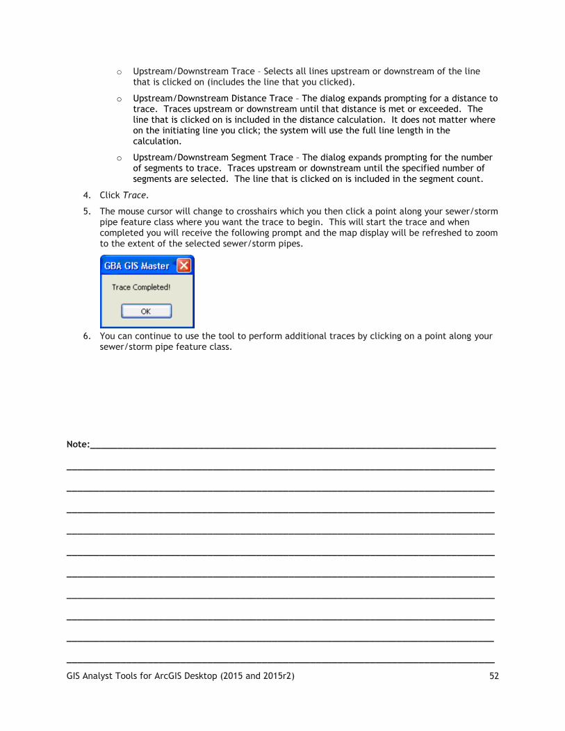
4. Click Trace.
5. The mouse cursor will change to crosshairs which you then click a point along your sewer/storm pipe feature class where you want the trace to begin. This will start the trace and when completed you will receive the following prompt and the map display will be refreshed to zoom to the extent of the selected sewer/storm pipes.
6. You can continue to use the tool to perform additional traces by clicking on a point along your sewer/storm pipe feature class.
Note:___________________________________________________________________________
_______________________________________________________________________________
_______________________________________________________________________________
_______________________________________________________________________________
_______________________________________________________________________________
_______________________________________________________________________________
_______________________________________________________________________________
_______________________________________________________________________________
_______________________________________________________________________________
_______________________________________________________________________________
_______________________________________________________________________________

GIS Analyst Tools for ArcGIS Desktop (2015 and 2015r2)
53
Update Sign Regulations The Update Sign Regulations tool allows users to assign a group of signs to a specific sign regulation. To use this tool, complete the following steps:
1. Using the ESRI selection tool, select a group of signs
2. Click the Update Sign Regulations tool .
o The System will check to make sure there is a Sign feature class in the project. If one is not found, you will be prompted to add one before using this tool.
3. If there is more than one feature layer with signs in your dataset, the Feature Layer Selection dialog will appear. Select the appropriate layer from the drop-down list.
4. Next, you'll see the MUTCD selection dialog, allowing you to choose the code for the sign you'd like to use.
o Signs are assigned to regulations based on the MUTCD (Manual on Uniform Traffic Control Device) code.
o You can highlight multiple signs in the list. The regulation you select in the following step will be applied to all highlighted signs.
5. Select a regulation from the right-hand grid. These regulations are included in the Regulation module and are then associated with the Sign Inventory module.
6. Click OK when you have finished making your selections. You’ll receive an error message if you do not have both an MUTCD code and Regulation highlighted.
7. Before the system runs this tool, you’ll receive a prompt informing you that the highlighted signs will be assigned to the regulation you selected even if they are already attached to an existing regulation. Select Yes or No to continue.
8. The system will now update the Regulation Manager. When this process is complete, a dialog will appear informing you of the number of records updated. You will then have the option to open and edit the sign regulation in the desktop application.
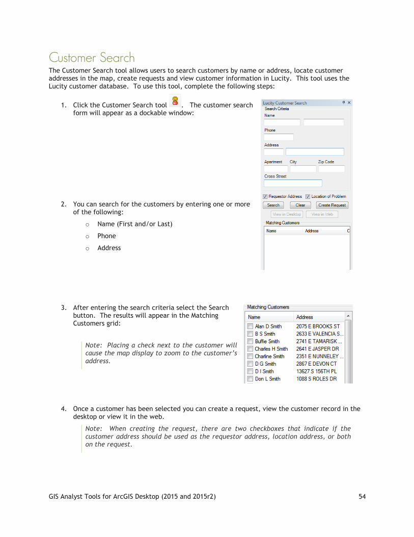
GIS Analyst Tools for ArcGIS Desktop (2015 and 2015r2)
54
Customer Search The Customer Search tool allows users to search customers by name or address, locate customer addresses in the map, create requests and view customer information in Lucity. This tool uses the Lucity customer database. To use this tool, complete the following steps:
1. Click the Customer Search tool . The customer search form will appear as a dockable window:
2. You can search for the customers by entering one or more of the following:
o Name (First and/or Last)
o Phone
o Address
3. After entering the search criteria select the Search button. The results will appear in the Matching Customers grid:
Note: Placing a check next to the customer will cause the map display to zoom to the customer’s address.
4. Once a customer has been selected you can create a request, view the customer record in the desktop or view it in the web.
Note: When creating the request, there are two checkboxes that indicate if the customer address should be used as the requestor address, location address, or both on the request.

GIS Analyst Tools for ArcGIS Desktop (2015 and 2015r2)
55
Find Feature
The find feature tool allows you to quickly locate a Lucity asset in the map based upon its common ID. To use this tool, complete the following steps:
1. Select an asset type from the drop down list.
o Only asset types for feature classes that are currently in the map are shown in the drop down list
o The "All Asset Types" option will search all feature classes linked to Lucity. Using this option will take longer to process.
2. Next, enter the asset ID (common ID) for the asset and click Find.
o You can use wildcards in the search parameter.
Use * for any number of characters. For example, 1269*8 will find any feature where the ID is starts with 1269 and ends with 8
Use ? for a set number of characters. For example, 1269?8 will find any feature where the ID is six characters in length and it starts with 1269 and ends with 8
3. To find the feature either hit the Enter key while the cursor is in the asset ID text box, or select the Find button.
4. The following dialog will appear, asking if you wish to clear the current map selection.
5. A dialog will appear indicating the results of the search. If any features are found that meet the criteria the map will zoom to the features and they will be selected.
Note:___________________________________________________________________________
_______________________________________________________________________________
_______________________________________________________________________________
_______________________________________________________________________________
_______________________________________________________________________________

GIS Analyst Tools for ArcGIS Desktop (2015 and 2015r2)
56
Lucity Field Links This tool performs a join between the feature class and its associated asset inventory table. To use this tool, complete the following steps:
1. Right-click on the feature class in the ArcMap table of contents, select Properties, and then select the Lucity Field Links tab.
2. This tab lists all the asset inventory fields for the module linked to the feature class. Place a check next to the fields you wish to have joined to your feature class.
o Check All Fields- Automatically places a check next to all the fields
o Uncheck All Fields- Removes the check next to all fields
o Save as User Default- Saves the fields that you have checked so the next time you use this tool you can simply load your previous setting. This is a user setting that is saved to the database.
o Load User Default- Loads previously saved setting. Use this to automatically update which fields are checked from a previous setting you may have saved.
3. Select a Join Option
o Keep all records- this keeps all records from your feature class visible even if there isn't a matching record in the desktop application.
o Keep Only Matching Records- this will result in your feature class only to display features that have a matching record within the desktop application. Features that do not exist in the desktop will not appear in the feature class.
4. Click Apply or OK to process the join.
5. The fields you had selected should now appear in the feature class.
Note: These fields are not editable! If you wish to remove the join, you can do so by right-clicking on the feature class and select Join and Relates>>Join>>Remove Join and selecting the Lucity join.

GIS Analyst Tools for ArcGIS Desktop (2015 and 2015r2)
57
Lucity Help
Not really sure why that was there. I have no problem with the entries under this point but they are on the GIS edit tool guide rather than the Analyst tool guide.
Lucity GIS Settings There are a couple new user specific settings with the Lucity GIS extension. One controls how the show in map should display request, work order and pm/work template records. The other setting controls the default symbology templates that should be used with various Lucity GIS tools.
To access these settings click on the Settings button located on the Lucity GIS Editor toolbar in ArcMap. The Lucity GIS Settings dialog will be displayed.
Show in Map Option for Work Modules The Lucity GIS Settings dialog will allow the user to specify how the Show In Map tool should display the location of Requests, Work Orders and PM/Work Templates. There are three options available:
o Assets- This option will only show the assets. Any address or x/y locations associated with the record will not be displayed. This option helps eliminate duplication of locational representation that can occur if you have the option set to automatically add the asset address to location grid.

GIS Analyst Tools for ArcGIS Desktop (2015 and 2015r2)
58
o Locations- This option will only show address and x/y locations associated with the record. Assets will not be displayed in the results.
o Assets and Locations- This is the default option. This option will show the location of all assets, addresses and x/y locations associated to the record.
1. To alter the default setting, from the Lucity GIS Settings dialog select the desired setting from the drop down for each of the three modules.
2. Click Save. This setting will take effect the next time ArcMap is reopened.
Symbology Defaults The Lucity GIS Settings dialog will allow the user to select layer files (.lyr) that will be used as symbology templates for various Lucity GIS tools.
1. In ArcMap, run the Lucity GIS tool (Lucity Views, Work Frequency, Work Location, or TV Observations) you wish to set default symbology for. The tool will produce a resulting feature class and it will be added to the .mxd.
2. Make any desired change to the properties of the feature class. Changes can include:
o Symbology (size, shape, color, symbol levels, etc)
o Labelling
o Scale Dependency
o Fields Displayed
o Etc…
Note: The Lucity GIS tools include a set of default fields in the result; however, some tools allow you to alter the results to include additional fields. If you make modifications where a non-default field is used for display (label, symbol, etc.) each time you run that tool in the future you must include that field in the results or your default template will not apply correctly or may fail all together.
3. In the table of contents right-click on the feature class and select “Save as Layer File…”
4. A save dialog will appear. Name the file and save it to a location where it can be stored long-term.
Note: If the tool generated more than one layer (points, lines, polygons) steps 3 and 4 must be repeated for each layer.
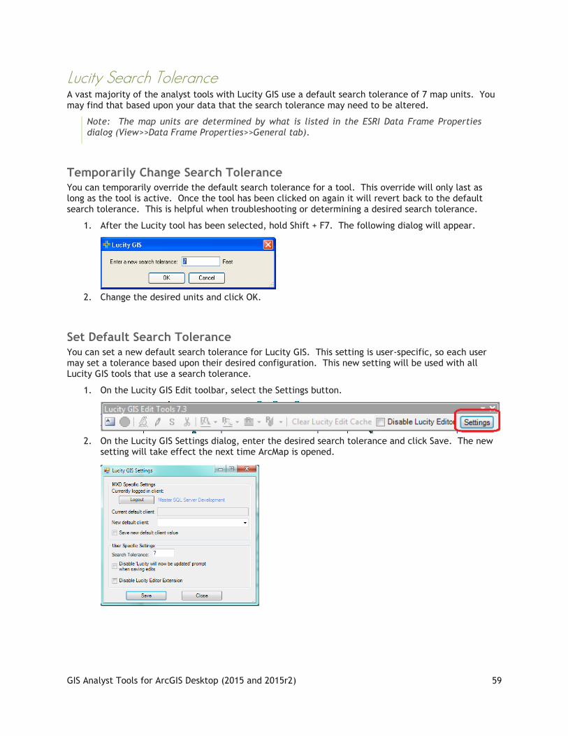
GIS Analyst Tools for ArcGIS Desktop (2015 and 2015r2)
59
Lucity Search Tolerance A vast majority of the analyst tools with Lucity GIS use a default search tolerance of 7 map units. You may find that based upon your data that the search tolerance may need to be altered.
Note: The map units are determined by what is listed in the ESRI Data Frame Properties dialog (View>>Data Frame Properties>>General tab).
Temporarily Change Search Tolerance You can temporarily override the default search tolerance for a tool. This override will only last as long as the tool is active. Once the tool has been clicked on again it will revert back to the default search tolerance. This is helpful when troubleshooting or determining a desired search tolerance.
1. After the Lucity tool has been selected, hold Shift + F7. The following dialog will appear.
2. Change the desired units and click OK.
Set Default Search Tolerance You can set a new default search tolerance for Lucity GIS. This setting is user-specific, so each user may set a tolerance based upon their desired configuration. This new setting will be used with all Lucity GIS tools that use a search tolerance.
1. On the Lucity GIS Edit toolbar, select the Settings button.
2. On the Lucity GIS Settings dialog, enter the desired search tolerance and click Save. The new
setting will take effect the next time ArcMap is opened.