Embed Size (px)
Citation preview
— 1ZSE 2750 -105 EN, RE V. 9
Transformer bushings type GOE and GOE(2)Technical guide
— Original instructionThe information provided in this document is intended to be general and does not cover all possible applications. Any specific application not covered should be referred directly to ABB, or its authorized representative.
We reserve the right to make technical changes or modify the contents of this document without prior notice. With regard to purchase orders, the agreed particulars shall prevail. ABB does not accept any responsibility whatsoever for potential errors or possible lack of information in this document.
We reserve all rights in this document and in the subject matter and illustrations contained therein. Any reproduction, disclosure to third parties or utilization of its contents – in whole or in parts – is forbidden without prior written consent of ABB.
— Table of contents
Design 5GOE features 6GOE(2) features 6Features and benefits 7Shed profile 7
Testing 8Test tap 8Test tap adapter 8Oil sampling valve 8
Dimensions and data 9Type designation 9Rating plate example 9GOE 250-210 to GOE 950-650 10GOE 1050-750 to GOE 1800-1360 12GOE 2550 14GOE 2600 15GOE(2) 16
Current capacity 18Short-time current 18Overload capacity of bushings 18
Connection details 19Draw rod system 19Draw lead system, GOE 21Draw lead system, GOE(2) 21Fixed bottom contact 22Outer terminal 22
End-shields 23
Ordering particulars 26
Packing 27
Additional GOE and GOE(2) bushings 28

TR A N S FO R M E R B U S H I N G S T Y PE G O E A N D G O E ( 2) TEC H N I C A L G U ID E 5
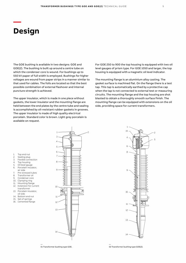
The GOE bushing is available in two designs: GOE and GOE(2). The bushing is built up around a centre tube on which the condenser core is wound. For bushings up to 550 kV paper of full width is employed. Bushings for higher voltages are wound from paper strips in a manner similar to that used for cables. The foils are located so that the best possible combination of external flashover and internal puncture strength is achieved.
The upper insulator, which is made in one piece without gaskets, the lower insulator and the mounting flange are held between the end plates by the centre tube and sealing is accomplished by oil-resistant rubber gaskets in grooves. The upper insulator is made of high quality electrical porcelain. Standard color is brown. Light grey porcelain is available on request.
For GOE 250 to 900 the top housing is equipped with two oil level gauges of prism type. For GOE 1050 and larger, the top housing is equipped with a magnetic oil level indicator.
The mounting flange is an aluminium alloy casting. The gasket surface is machined flat. On the flange there is a test tap. This tap is automatically earthed by a protective cap when the tap is not connected to external test or measuring circuits. The mounting flange and the top housing are shot blasted to obtain a thoroughly smooth surface finish. The mounting flange can be equipped with extensions on the oil side, providing space for current transformers.
—Design
—01 Transformer bushing type GOE.
—02 Transformer bushing type GOE(2).
1. Top end nut2. Sealing plug3. Flexible connection4. Top housing5. Oil level gauge6. Porcelain insulator,
air side7. Pre-stressed tubes8. Transformer oil9. Condenser core10. Clamping ring11. Mounting flange12. Extension for current
transformer13. Porcelain insulator,
oil side14. Bottom end nut15. Set of springs16. Cemented flange
12
1
15
9
8
6
4
16
14
13
11
2
5
12
13
1
3
9
8
7
6
4
5
14
11
10
2
6 TR A N S FO R M E R B U S H I N G S T Y PE G O E A N D G O E ( 2) TEC H N I C A L G U ID E
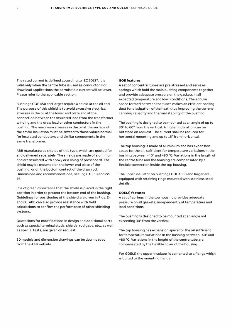
The rated current is defined according to IEC 60137. It is valid only when the centre tube is used as conductor. For draw lead applications the permissible current will be lower. Please refer to the applicable section.
Bushings GOE 450 and larger require a shield at the oil end. The purpose of this shield is to avoid excessive electrical stresses in the oil at the lower end plate and at the connection between the insulated lead from the transformer winding and the draw lead or other conductors in the bushing. The maximum stresses in the oil at the surface of the shield insulation must be limited to those values normal for insulated conductors and similar components in the same transformer.
ABB manufactures shields of this type, which are quoted for and delivered separately. The shields are made of aluminium and are insulated with epoxy or a lining of pressboard. The shield may be mounted on the lower end plate of the bushing, or on the bottom contact of the draw rod. Dimensions and recommendations, see Figs. 18, 19 and 22-26.
It is of great importance that the shield is placed in the right position in order to protect the bottom end of the bushing. Guidelines for positioning of the shield are given in Figs. 24 and 26. ABB can also provide assistance with field calculations to confirm the performance of other shielding systems.
Quotations for modifications in design and additional parts such as special terminal studs, shields, rod gaps, etc., as well as special tests, are given on request.
3D models and dimension drawings can be downloaded from the ABB website.
GOE featuresA set of concentric tubes are pre stressed and serve as springs which hold the main bushing components together and provide adequate pressure on the gaskets in all expected temperature and load conditions. The annular space formed between the tubes makes an efficient cooling duct for dissipation of the heat, thus improving the current-carrying capacity and thermal stability of the bushing.
The bushing is designed to be mounted at an angle of up to 30° to 60° from the vertical. A higher inclination can be obtained on request. The current shall be reduced for horizontal mounting and up to 15° from horizontal.
The top housing is made of aluminium and has expansion space for the oil, sufficient for temperature variations in the bushing between -40° and +80 °C. Variations in the length of the centre tube and the housing are compensated by a flexible connection inside the top housing.
The upper insulator on bushings GOE 1050 and larger are equipped with retaining rings mounted with stainless steel details.
GOE(2) featuresA set of springs in the top housing provides adequate pressure on all gaskets, independently of temperature and load conditions.
The bushing is designed to be mounted at an angle not exceeding 30° from the vertical.
The top housing has expansion space for the oil sufficient for temperature variations in the bushing between -40° and +80 °C. Variations in the lenght of the centre tube are compensated by the flexible cover of the housing.
For GOE(2) the upper insulator is cemented to a flange which is bolted to the mounting flange.
TR A N S FO R M E R B U S H I N G S T Y PE G O E A N D G O E ( 2) TEC H N I C A L G U ID E 7
Features and benefits• A complete range and outstanding operational experience
from the most demanding applications for more than 30 years.
• Our unique draw rod system facilitates easy field installation and removal without lowering the oil level.
• The worlds most used 800 kV bushing. Never any failures in the field.
• 3D models makes it easy to incorporate the bushing in its context.
• We use a sealing system proven since 40 years around the world.
• Our test criteria and margins exceeding international standards.
• Only extra long creepage shed profile.
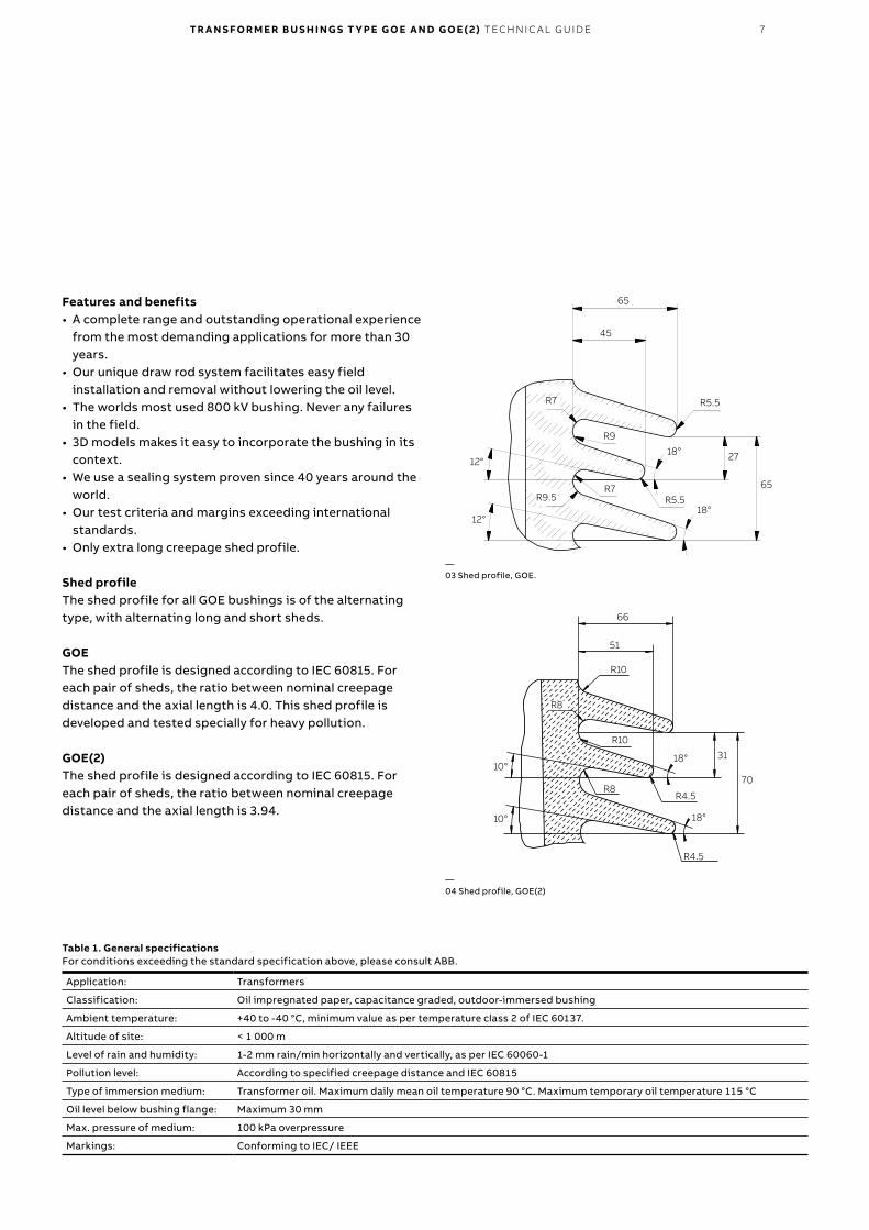
Shed profileThe shed profile for all GOE bushings is of the alternating type, with alternating long and short sheds.
GOEThe shed profile is designed according to IEC 60815. For each pair of sheds, the ratio between nominal creepage distance and the axial length is 4.0. This shed profile is developed and tested specially for heavy pollution.
GOE(2)The shed profile is designed according to IEC 60815. For each pair of sheds, the ratio between nominal creepage distance and the axial length is 3.94.
65
45
R5.5
27
65
18°
R5.518°
12°
12°
R7
R9.5
R9
R7
R10
R10
R8
18°
R8
R4.5
18°
R4.5
10°
10°
66
51
31
70
—03 Shed profile, GOE.
—04 Shed profile, GOE(2)
Table 1. General specificationsFor conditions exceeding the standard specification above, please consult ABB.
Application: Transformers
Classification: Oil impregnated paper, capacitance graded, outdoor-immersed bushing
Ambient temperature: +40 to -40 °C, minimum value as per temperature class 2 of IEC 60137.
Altitude of site: < 1 000 m
Level of rain and humidity: 1-2 mm rain/min horizontally and vertically, as per IEC 60060-1
Pollution level: According to specified creepage distance and IEC 60815
Type of immersion medium: Transformer oil. Maximum daily mean oil temperature 90 °C. Maximum temporary oil temperature 115 °C
Oil level below bushing flange: Maximum 30 mm
Max. pressure of medium: 100 kPa overpressure
Markings: Conforming to IEC/ IEEE
8 TR A N S FO R M E R B U S H I N G S T Y PE G O E A N D G O E ( 2) TEC H N I C A L G U ID E
—Testing
—06 Test tap adapter.
—07 Oil sampling valve.
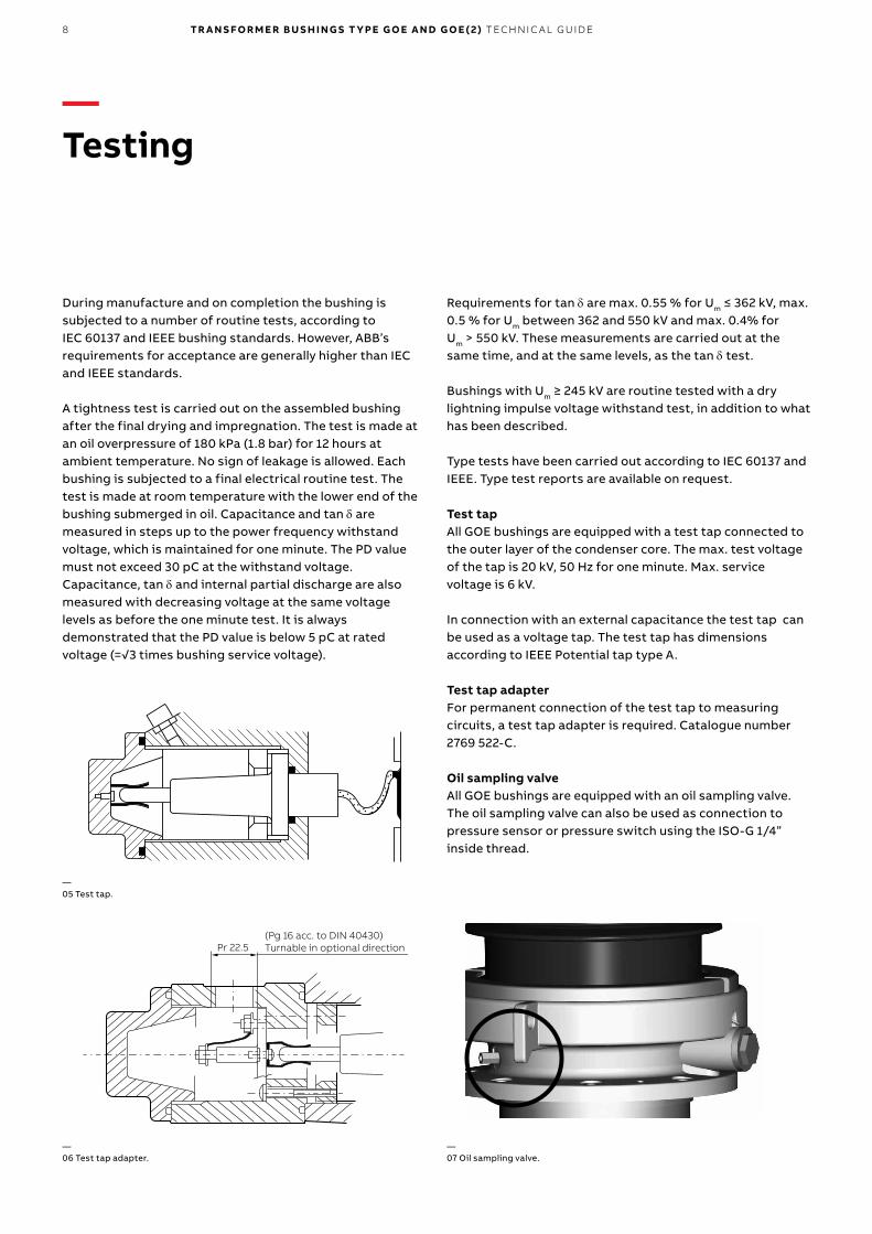
—05 Test tap.
During manufacture and on completion the bushing is subjected to a number of routine tests, according to IEC 60137 and IEEE bushing standards. However, ABB’s requirements for acceptance are generally higher than IEC and IEEE standards.
A tightness test is carried out on the assembled bushing after the final drying and impregnation. The test is made at an oil overpressure of 180 kPa (1.8 bar) for 12 hours at ambient temperature. No sign of leakage is allowed. Each bushing is subjected to a final electrical routine test. The test is made at room temperature with the lower end of the bushing submerged in oil. Capacitance and tan d are measured in steps up to the power frequency withstand voltage, which is maintained for one minute. The PD value must not exceed 30 pC at the withstand voltage. Capacitance, tan d and internal partial discharge are also measured with decreasing voltage at the same voltage levels as before the one minute test. It is always demonstrated that the PD value is below 5 pC at rated voltage (=√3 times bushing service voltage).
Requirements for tan d are max. 0.55 % for Um ≤ 362 kV, max. 0.5 % for Um between 362 and 550 kV and max. 0.4% for Um > 550 kV. These measurements are carried out at the same time, and at the same levels, as the tan d test.
Bushings with Um ≥ 245 kV are routine tested with a dry lightning impulse voltage withstand test, in addition to what has been described.
Type tests have been carried out according to IEC 60137 and IEEE. Type test reports are available on request.
Test tapAll GOE bushings are equipped with a test tap connected to the outer layer of the condenser core. The max. test voltage of the tap is 20 kV, 50 Hz for one minute. Max. service voltage is 6 kV.
In connection with an external capacitance the test tap can be used as a voltage tap. The test tap has dimensions according to IEEE Potential tap type A.
Test tap adapterFor permanent connection of the test tap to measuring circuits, a test tap adapter is required. Catalogue number 2769 522-C.
Oil sampling valveAll GOE bushings are equipped with an oil sampling valve. The oil sampling valve can also be used as connection to pressure sensor or pressure switch using the ISO-G 1/4” inside thread.
(Pg 16 acc. to DIN 40430)Turnable in optional directionPr 22.5
TR A N S FO R M E R B U S H I N G S T Y PE G O E A N D G O E ( 2) TEC H N I C A L G U ID E 9
—Dimensions and data
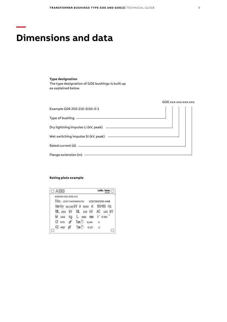
Example GOE 250-210-3150-0.3
Type of bushing
Dry lightning impulse LI (kV, peak)
Wet switching impulse SI (kV, peak)
Rated current (A)
Flange extension (m)
Type designationThe type designation of GOE bushings is built up as explained below.
Rating plate example
GOE xxx-xxx-xxx-xxx
492 0,13
0,44570
985240 0-60
250 210 120
52/30 3150
1ZSC902052-AAB
GOE250-210-3150-0,6
1ZSCT14006483/02
2019
10 TR A N S FO R M E R B U S H I N G S T Y PE G O E A N D G O E ( 2) TEC H N I C A L G U ID E
Tab
le 3
. Dim
ensi
ons
GO
E 25
0 to
950
.
Cat
alo
g N
umb
erTy
pe
des
igna
tio
n
Flan
ge
exte
nsio
n m
Cre
epag
e d
ista
nce
mm
D1
mm
L1m
mL2
mm
L3m
mL4
mm
L5±5
mm
Mas
skg
D2
mm
D3
mm
D4
mm
D5
mm
D6
mm
A1
A2
H1
mm
1ZS
C9
02
052
-AA
AG
OE
250
-210
-315
0-0
.30.
32
955
±8
0 4
88
25 ±
20
1331
±25
30
537
56
8523
022
435
03
86
350
30
06
06
02
0 (6
x)
-AA
BG
OE
250
-210
-315
0-0
.60.
62
955
±8
0 4
88
25 ±
20
1331
±25
60
56
709
8524
022
435
03
86
350
30
06
06
02
0 6x
)
-AB
AG
OE
250
-210
-50
00
-0.3
0.3
295
5 ±
80
38
825
±2
013
31 ±
253
05
375
685
270
224
350
38
635
03
00
60
60
20
(6x)
-AB
BG
OE
250
-210
-50
00
-0.6
0.6
295
5 ±
80
38
825
±2
013
31 ±
256
05
670
985
29
022
435
03
86
350
30
06
06
02
0 (6
x)
1ZS
C9
02
072-
AA
AG
OE
38
0-3
00
-315
0-0
.30.
32
955
±8
0 4
88
25 ±
20
1331
±25
30
537
56
8523
022
435
03
86
350
30
06
06
02
0 (6
x)
-AA
BG
OE
38
0-3
00
-315
0-0
.60.
62
955
±8
0 4
88
25 ±
20
1331
±25
60
56
709
8524
022
435
03
86
350
30
06
06
02
0 (6
x)
-AB
AG
OE
38
0-3
00
-50
00
-0.3
0.3
295
5 ±
80
38
825
±2
013
31 ±
253
05
375
685
270
224
350
38
635
03
00
60
60
20
(6x)
-AB
BG
OE
38
0-3
00
-50
00
-0.6
0.6
295
5 ±
80
38
825
±2
013
31 ±
256
05
670
985
29
022
435
03
86
350
30
06
06
02
0 (6
x)
1ZS
C9
021
45
-AA
AG
OE
650
-50
0-3
150
-0.3
0.3
4775
±12
54
813
00
±27
180
6 ±3
33
05
40
083
533
026
44
00
38
635
035
04
59
02
0 (8
x)
-AA
BG
OE
650
-50
0-3
150
-0.6
0.6
4775
±12
54
813
00
±27
180
6 ±3
36
05
700
1135
350
264
40
03
86
350
350
45
90
20
(8x)
-AB
AG
OE
650
-50
0-5
00
0-0
.30.
347
75 ±
125
38
130
0 ±2
718
06
±33
30
54
00
835
39
026
44
00
38
635
035
04
59
02
0 (8
x)
-AB
BG
OE
650
-50
0-5
00
0-0
.60.
647
75 ±
125
38
130
0 ±2
718
06
±33
60
570
011
3541
026
44
00
38
635
035
04
59
02
0 (8
x)
1ZS
C9
021
70-A
AA
GO
E 95
0-6
50
-315
0-0
.30.
36
82
0 ±1
754
818
00
±37
230
6 ±4
23
05
315
835
40
526
44
00
38
635
035
04
59
02
0 (8
x)
-AA
BG
OE
950
-65
0-3
150
-0.6
0.6
68
20
±175
48
180
0 ±3
723
06
±42
60
561
511
354
20
264
40
03
86
350
350
45
90
20
(8x)
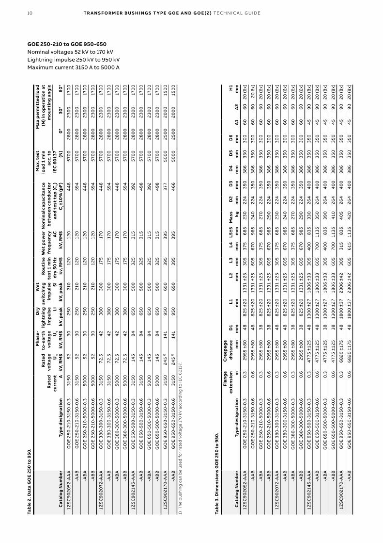
GOE 250-210 to GOE 950-650Nominal voltages 52 kV to 170 kVLightning impulse 250 kV to 950 kVMaximum current 3150 A to 5000 A
Tab
le 2
. Dat
a G
OE
250
to 9
50.
Cat
alo
g N
umb
erTy
pe
des
igna
tio
n
Rat
ed
curr
ent A
Rat
ed
volt
age
Um
kV, R
MS
Phas
e-to
-ear
th
volt
age UY
kV, R
MS
Dry
lig
htni
ng
imp
ulse LI
kV, p
eak
Wet
sw
itch
ing
imp
ulse SI
kV, p
eak
Ro
utin
e te
st 1
min
d
ry 5
0 H
zkv
, RM
S
Wet
pow
er
freq
uenc
yA
CkV
, RM
S
No
min
al c
apac
itan
ce
bet
wee
n co
nduc
tor
and
test
tap
(C1)
C1±
10%
(p
F)
Max
. tes
t lo
ad 1
min
ac
c. t
oIE
C 6
0137
(N
)
Max
per
mit
ted
load
(N
) in
op
erat
ion
at
mo
unti
ng a
ngle
0°30
°6
0°
1ZS
C9
02
052
-AA
AG
OE
250
-210
-315
0-0
.331
50
523
025
021
012
012
04
48
570
028
00
230
017
00
-AA
BG
OE
250
-210
-315
0-0
.631
50
523
025
021
012
012
059
457
00
280
023
00
170
0
-AB
AG
OE
250
-210
-50
00
-0.3
50
00
523
025
021
012
012
0 4
48
570
028
00
230
017
00
-AB
BG
OE
250
-210
-50
00
-0.6
50
00
523
025
021
012
012
059
457
00
280
023
00
170
0
1ZS
C9
02
072-
AA
AG
OE
38
0-3
00
-315
0-0
.331
50
72.5
42
38
03
00
175
170
44
857
00
280
023
00
170
0
-AA
BG
OE
38
0-3
00
-315
0-0
.631
50
72.5
42
38
03
00
175
170
594
570
028
00
230
017
00
-AB
AG
OE
38
0-3
00
-50
00
-0.3
50
00
72.5
42
38
03
00
175
170
44
857
00
280
023
00
170
0
-AB
BG
OE
38
0-3
00
-50
00
-0.6
50
00
72.5
42
38
03
00
175
170
594
570
028
00
230
017
00
1ZS
C9
021
45
-AA
AG
OE
650
-50
0-3
150
-0.3
315
014
58
465
05
00
325
315
392
570
028
00
230
017
00
-AA
BG
OE
650
-50
0-3
150
-0.6
315
014
58
465
05
00
325
315
498
570
028
00
230
017
00
-AB
AG
OE
650
-50
0-5
00
0-0
.35
00
014
58
465
05
00
325
315
392
570
028
00
230
017
00
-AB
BG
OE
650
-50
0-5
00
0-0
.65
00
014
58
465
05
00
325
315
498
570
028
00
230
017
00
1ZS
C9
021
70-A
AA
GO
E 95
0-6
50
-315
0-0
.331
50
245 1
)14
195
065
03
953
9537
75
00
025
00
20
00
150
0
-AA
BG
OE
950
-65
0-3
150
-0.6
315
024
5 1)
141
950
650
395
395
46
65
00
025
00
20
00
150
01)
Th
e b
ush
ing
can
be
use
d f
or
rate
d v
olt
age
170
kV
acc
ord
ing
to
IEC
60
137.
TR A N S FO R M E R B U S H I N G S T Y PE G O E A N D G O E ( 2) TEC H N I C A L G U ID E 11
A2
130
A1Position of test tap
Mounting hole H1
Earthing hole M12
Position of oil sample valve
D6
D2
D3
D1
25
115
L3L4
L1L2
L5
D5
D4
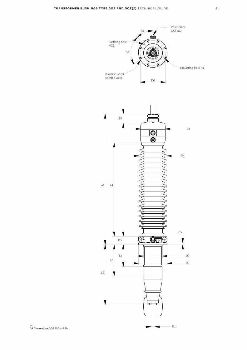
—08 Dimensions GOE 250 to 950.
12 TR A N S FO R M E R B U S H I N G S T Y PE G O E A N D G O E ( 2) TEC H N I C A L G U ID E
Tab
le 5
. Dim
ensi
ons
GO
E 10
50 t
o 18
00.
Cat
alo
g N
umb
erTy
pe
des
igna
tio
n
Flan
ge
exte
nsio
n m
Cre
epag
e d
ista
nce
mm
D1
mm
L1m
mL2
mm
L3m
mL4
mm
L5±5
mm
Mas
skg
D2
mm
D3
mm
D4
mm
D5
mm
D6
mm
A1
H1
mm
1ZS
C9
022
45
-AA
AG
OE
105
0-7
50
-25
00
-0.3
0.3
819
0 ±2
104
822
30
±55
307
1 ±6
03
05
39
010
3576
533
04
80
485
50
043
04
52
0 (8
x)
-AA
BG
OE
105
0-7
50
-25
00
-0.6
0.6
819
0 ±2
104
822
30
±55
307
1 ±6
06
05
655
1335
785
330
48
04
855
00
430
45
20
(8x)
-AB
AG
OE
105
0-7
50
-50
00
-0.3
0.3
819
0 ±2
103
822
30
±55
307
1 ±6
03
05
39
010
358
80
330
48
04
855
00
430
45
20
(8x)
-AB
BG
OE
105
0-7
50
-50
00
-0.6
0.6
819
0 ±2
103
822
30
±55
307
1 ±6
06
05
655
1335
916
330
48
04
855
00
430
45
20
(8x)
1ZS
C9
023
62-
AA
AG
OE
1175
-85
0-2
50
0-0
.30.
391
20
±24
04
824
70 ±
5533
11 ±
60
30
533
510
3581
033
04
80
485
50
043
04
52
0 (8
x)
-AA
BG
OE
1175
-85
0-2
50
0-0
.60.
691
20
±24
04
824
70 ±
5533
11 ±
60
60
561
013
3583
033
04
80
485
50
043
04
52
0 (8
x)
1ZS
C9
024
20
-AA
AG
OE
130
0-1
05
0-2
50
0-0
.30.
313
745
±355
48
362
0 ±5
64
461
±6
03
05
320
1035
1070
330
48
04
855
00
430
45
20
(8x)
-AA
BG
OE
130
0-1
05
0-2
50
0-0
.60.
613
745
±355
48
362
0 ±5
64
461
±6
06
05
62
013
3510
90
330
48
04
855
00
430
45
20
(8x)
-BA
AG
OE
1425
-115
0-2
50
0-0
.30.
313
745
±355
48
362
0 ±5
64
461
±6
03
05
320
1035
1070
330
48
04
855
00
430
45
20
(8x)
-BA
BG
OE
1425
-115
0-2
50
0-0
.60.
613
745
±355
48
362
0 ±5
64
461
±6
06
05
62
013
3510
90
330
48
04
855
00
430
45
20
(8x)
1ZS
C9
025
50
-AA
AG
OE
155
0-1
175
-25
00
-0.3
0.3
180
20
±470
48
4710
±55
5751
±61
30
531
012
8519
954
2872
05
656
00
66
03
024
(12
x)
-AA
BG
OE
155
0-1
175
-25
00
-0.6
0.6
180
20
±470
48
4710
±55
5751
±61
60
561
015
852
030
428
720
565
60
06
60
30
24 (1
2x)
-BA
AG
OE
1675
-13
00
-25
00
-0.3
0.3
180
20
±470
48
4710
±55
5751
±61
30
531
012
8519
954
2872
05
656
00
66
03
024
(12
x)
-BA
BG
OE
1675
-13
00
-25
00
-0.6
0.6
180
20
±470
48
4710
±55
5751
±61
60
561
015
852
030
428
720
565
60
06
60
30
24 (1
2x)
-CA
AG
OE
180
0-1
360
-25
00
-0.3
0.3
180
20
±470
48
4710
±55
5751
±61
30
531
012
8519
954
2872
05
656
00
66
03
024
(12
x)
-CA
BG
OE
180
0-1
360
-25
00
-0.6
0.6
180
20
±470
48
4710
±55
5751
±61
60
561
015
852
030
428
720
565
60
06
60
30
24 (1
2x)
Tab
le 4
. Dat
a G
OE
1050
to
180
0.
Cat
alo
g N
umb
erTy
pe
des
igna
tio
n
Rat
ed
curr
ent A
Rat
ed
volt
age
Um
kV, R
MS
Phas
e-to
-ear
th
volt
age UY
kV, R
MS
Dry
lig
htni
ng
imp
ulse LI
kV, p
eak
Wet
sw
itch
ing
imp
ulse SI
kV, p
eak
Ro
utin
e te
st 1
min
d
ry 5
0 H
zkv
, RM
S
Wet
pow
er
freq
uenc
yA
CkV
, RM
S
Dry
sw
itch
ing
imp
ulse
kV, p
eak
Nom
inal
cap
acit
ance
be
twee
n co
nduc
tor
and
test
tap
(C1)
C1±1
0% (p
F)
Max
. tes
t lo
ad 1
m
in a
cc.
to IE
C
601
37 (
N)
Max
per
mit
ted
load
(N
) in
op
erat
ion
at
mo
unti
ng a
ngle
0°30
°6
0°
1ZS
C9
022
45
-AA
AG
OE
105
0-7
50
-25
00
-0.3
250
036
2 1)
20
910
50
750
50
54
80
825
373
130
00
650
043
00
310
0
-AA
BG
OE
105
0-7
50
-25
00
-0.6
250
036
2 1)
20
910
50
750
50
54
80
825
431
130
00
650
043
00
310
0
-AB
AG
OE
105
0-7
50
-50
00
-0.3
50
00
362 1
)2
09
105
075
05
05
48
08
253
8313
00
065
00
430
031
00
-AB
BG
OE
105
0-7
50
-50
00
-0.6
50
00
362 1
)2
09
105
075
05
05
48
08
2543
113
00
065
00
430
031
00
1ZS
C9
023
62-
AA
AG
OE
1175
-85
0-2
50
0-0
.325
00
362
20
911
7585
05
60
56
095
03
9112
00
06
00
043
00
310
0
-AA
BG
OE
1175
-85
0-2
50
0-0
.625
00
362
20
911
7585
05
60
56
095
04
6512
00
06
00
043
00
310
0
1ZS
C9
024
20
-AA
AG
OE
130
0-1
05
0-2
50
0-0
.325
00
42
024
213
00
105
063
0n
.a.
1155
518
90
00
45
00
250
0-
-AA
BG
OE
130
0-1
05
0-2
50
0-0
.625
00
42
024
213
00
105
063
0n
.a.
1155
54
09
00
04
50
025
00
-
-BA
AG
OE
1425
-115
0-2
50
0-0
.325
00
42
024
214
2511
50
695
n.a
.12
6551
89
00
04
50
025
00
-
-BA
BG
OE
1425
-115
0-2
50
0-0
.625
00
42
024
214
2511
50
695
n.a
.12
655
40
90
00
45
00
250
0-
1ZS
C9
025
50
-AA
AG
OE
155
0-1
175
-25
00
-0.3
250
055
031
815
50
1175
750
n.a
.13
00
46
413
00
065
00
430
015
00
-AA
BG
OE
155
0-1
175
-25
00
-0.6
250
055
031
815
50
1175
750
n.a
.13
00
45
813
00
065
00
430
015
00
-BA
AG
OE
1675
-13
00
-25
00
-0.3
250
055
031
816
7513
00
750
n.a
.14
30
46
413
00
065
00
430
015
00
-BA
BG
OE
1675
-13
00
-25
00
-0.6
250
055
031
816
7513
00
750
n.a
.14
30
45
813
00
065
00
430
015
00
-CA
AG
OE
180
0-1
360
-25
00
-0.3
250
055
031
818
00
136
087
0n
.a.
150
04
64
130
00
650
043
00
150
0
-CA
BG
OE
180
0-1
360
-25
00
-0.6
250
055
031
818
00
136
087
0n
.a.
150
04
58
130
00
650
043
00
150
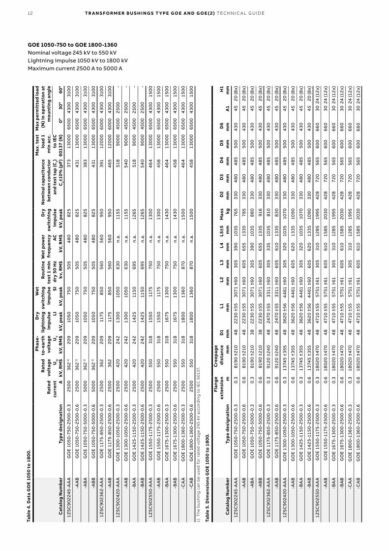
01)
Th
e b
ush
ing
can
be
use
d f
or
rate
d v
olt
age
245
kV a
cco
rdin
g t
o IE
C 6
013
7.
GOE 1050-750 to GOE 1800-1360Nominal voltage 245 kV to 550 kVLightning impulse 1050 kV to 1800 kVMaximum current 2500 A to 5000 A
TR A N S FO R M E R B U S H I N G S T Y PE G O E A N D G O E ( 2) TEC H N I C A L G U ID E 13
150
L1L2
A1Position of test tap
Mounting hole H1
Earthing hole M12
Position of oil sample valve
90°
D4
D5
D2
D3
D1
28
196
L3L4
L5
D6
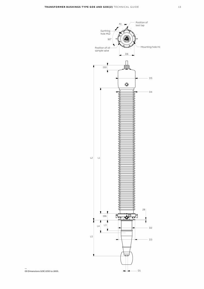
—09 Dimensions GOE 1050 to 1800.
14 TR A N S FO R M E R B U S H I N G S T Y PE G O E A N D G O E ( 2) TEC H N I C A L G U ID E
Tab
le 7
. Dim
ensi
ons
GO
E 25
50.
Cat
alo
g N
umb
erTy
pe
des
igna
tio
nFl
ang
e ex
tens
ion m
Cre
epag
e d
ista
nce
mm
D1
mm
D2
mm
L1m
mL2
mm
L3m
mL4
mm
L5±5
mm
Mas
skg
1ZS
C9
028
00
-AA
AG
OE
255
0-1
675
-25
00
-0.6
0.6
2572
0 ±6
706
655
6561
9575
56
±63
60
56
40
1955
3673
-AA
BG
OE
255
0-1
675
-25
00
-0.9
0.9
2572
0 ±6
706
655
6561
9575
56
±63
90
59
40
2255
3733
1ZS
C9
028
00
-AA
CG
OE
255
0-1
60
0-0
.30.
323
736
±712
655
555
66
90
80
51 ±
633
05
34
016
552
924
-AA
DG
OE
255
0-1
60
0-0
.60.
623
736
±712
655
555
66
90
80
51 ±
636
05
64
019
552
974
Tab
le 6
. Dat
a G
OE
2550
.
Cat
alo
g N
umb
erTy
pe
des
igna
tio
n
Rat
ed
curr
ent A
Rat
ed
volt
age
Um
kV, R
MS
Phas
e-to
-ear
th
volt
age UY
kV, R
MS
Dry
lig
htni
ng
imp
ulse LI
kV, p
eak
Wet
sw
itch
ing
imp
ulse SI
kV, p
eak
Ro
utin
e te
st 1
min
d
ry 5
0 H
zkV
, RM
S
Dry
sw
itch
ing
imp
ulse
kV, p
eak
No
min
al c
apac
itan
ce
bet
wee
n co
nduc
tor
and
test
tap
(C1)
C1±
10%
(p
F)
Max
. tes
t lo
ad 1
min
ac
c. t
o IE
C 6
0137
(N
)
Max
per
mit
ted
load
(N
) in
op
erat
ion
at
mo
unti
ng a
ngle
0°30
°6
0°
1ZS
C9
028
00
-AA
AG
OE
2550
-167
5-2
500
-0.6
250
080
046
225
5016
7510
7518
5058
512
200
610
029
00
-
AA
BG
OE
2550
-167
5-2
500
-0.9
250
080
046
225
5016
7510
7518
5066
912
200
610
029
00
-
1ZS
C9
028
00
-AA
CG
OE
2550
-16
00
-0.3
250
080
046
225
5016
00
1075
176
052
013
00
065
00
370
016
00
-AA
DG
OE
2550
-16
00
-0.6
250
080
046
225
5016
00
1075
176
056
013
00
065
00
370
016
00
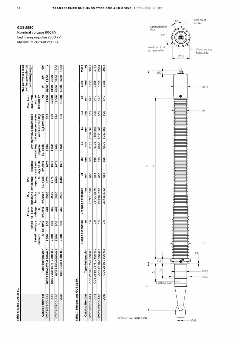
GOE 2550Nominal voltage 800 kVLightning impulse 2550 kVMaximum current 2500 A
150
L2 L1
30° Position of test tap
12 mounting holes Ø32
Earthing hole M12
Position of oil sample valve
90°
Ø616
D2
28
Ø528
D1
Ø780
Ø48
215
L3L4
L5Earthed layer
Ø711
—10 Dimensions GOE 2550.
TR A N S FO R M E R B U S H I N G S T Y PE G O E A N D G O E ( 2) TEC H N I C A L G U ID E 15
Tab
le 9
. Dim
ensi
ons
GO
E 26
00.
Cat
alo
g N
umb
erTy
pe
des
igna
tio
n
Flan
ge
exte
nsio
n m
Cre
epag
e d
ista
nce
mm
Mas
skg
1ZS
C9
021
10-A
AA
GO
E 26
00
-195
0-2
50
0-0
.50.
5>3
30
00
60
00
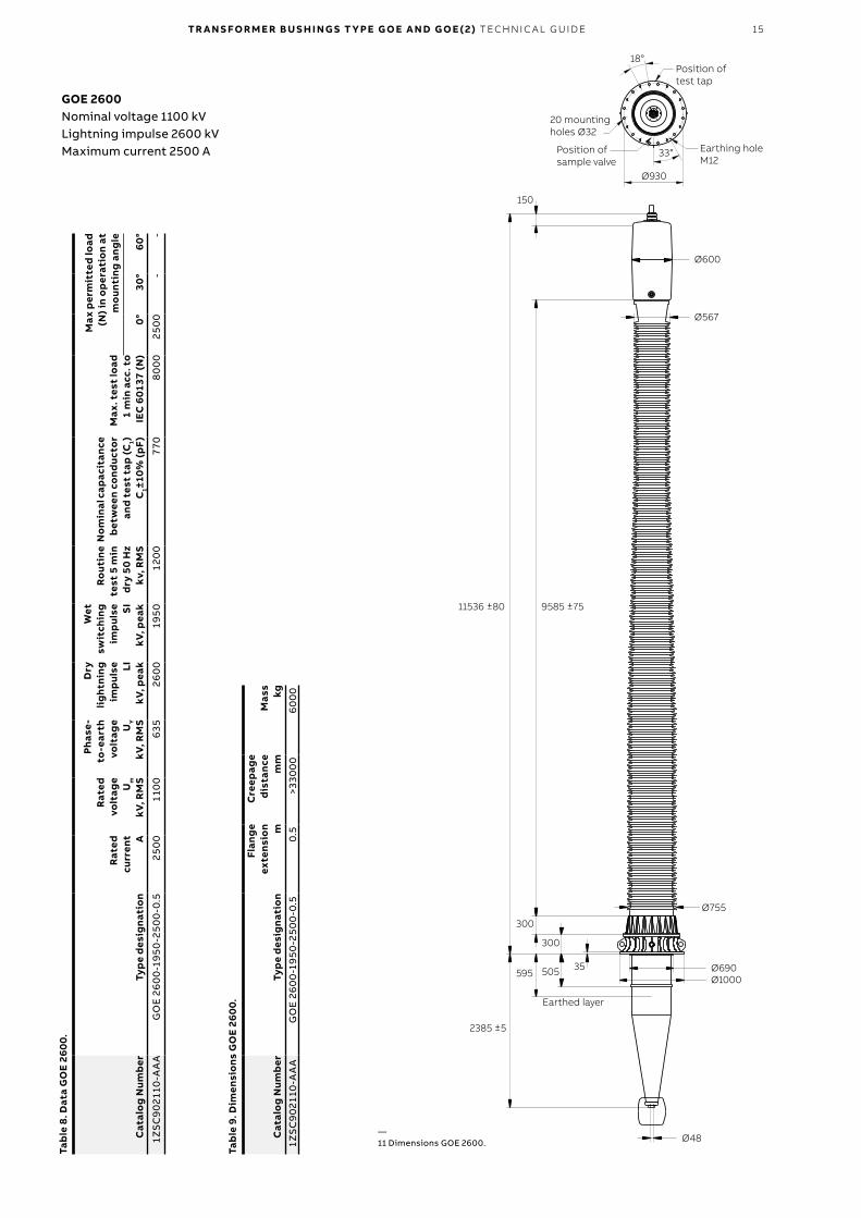
GOE 2600Nominal voltage 1100 kVLightning impulse 2600 kVMaximum current 2500 A
Tab
le 8
. Dat
a G
OE
260
0.
Cat
alo
g N
umb
erTy
pe
des
igna
tio
n
Rat
ed
curr
ent A
Rat
ed
volt
age
Um
kV, R
MS
Phas
e-to
-ear
th
volt
age UY
kV, R
MS
Dry
lig
htni
ng
imp
ulse LI
kV, p
eak
Wet
sw
itch
ing
imp
ulse SI
kV, p
eak
Ro
utin
e te
st 5
min
d
ry 5
0 H
zkv
, RM
S
No
min
al c
apac
itan
ce
bet
wee
n co
nduc
tor
and
test
tap
(C1)
C1±
10%
(p
F)
Max
. tes
t lo
ad
1 m
in a
cc. t
o IE
C 6
0137
(N
)
Max
per
mit
ted
load
(N
) in
op
erat
ion
at
mo
unti
ng a
ngle
0°30
°6
0°
1ZS
C9
021
10-A
AA
GO
E 26
00
-195
0-2
50
0-0
.525
00
110
063
526
00
195
012
00
770
80
00
250
0-
-
—11 Dimensions GOE 2600.
150
2385 ±5
9585 ±7511536 ±80
18°
33°
Position of test tap
Position of sample valve
20 mounting holes Ø32
Earthing hole M12
Ø600
Ø567
Ø755
Ø690Ø1000
Ø48
35
300
300
595 505
Earthed layer
Ø930
16 TR A N S FO R M E R B U S H I N G S T Y PE G O E A N D G O E ( 2) TEC H N I C A L G U ID E
Tab
le 1
0. D
ata
GO
E(2)
.
Cat
alo
g N
umb
erTy
pe
des
igna
tio
n
Rat
ed
curr
ent A
Rat
ed
volt
age
Um
kV, R
MS
Phas
e-to
-ear
th
volt
age UY
kV, R
MS
Dry
lig
htni
ng
imp
ulse LI
kV, p
eak
Wet
sw
itch
ing
imp
ulse SI
kV, p
eak
Ro
utin
e te
st 1
min
d
ry 5
0 H
zkv
, RM
S
Wet
pow
er
freq
uenc
yA
CkV
, RM
S
Dry
sw
itch
ing
imp
ulse
kV, p
eak
No
min
al c
apac
itan
ce
bet
wee
n co
nduc
tor
and
test
tap
(C1)
C1±
10%
(p
F)
Max
. tes
t lo
ad 1
m
in a
cc.
to IE
C
601
37 (
N)
Max
per
mit
ted
load
(N
) in
op
erat
ion
at
mo
unti
ng a
ngle
0°30
°6
0°
1ZS
C9
0336
2-A
AA
GO
E(2)
117
5-8
50
-16
00
-0.3
160
036
22
09
1175
850
56
0n
.a.
950
379
100
00
50
00
44
00
-
-AA
BG
OE(
2) 1
175
-85
0-1
60
0-0
.616
00
362
20
911
7585
05
60
n.a
.95
043
710
00
05
00
04
40
0-
1ZS
C9
034
20
-AA
AG
OE(
2) 1
425
-10
50
-16
00
-0.3
160
04
20
243
1425
105
06
95n
.a.
105
043
910
00
05
00
041
00
-
-AA
BG
OE(
2) 1
425
-10
50
-16
00
-0.6
160
04
20
243
1425
105
06
95n
.a.
105
04
88
100
00
50
00
410
0-
1ZS
C9
0355
0-A
AA
GO
E(2)
155
0-1
175
-16
00
-0.3
160
055
031
815
50
1175
750
n.a
.11
754
5910
00
05
00
03
90
0-
-AA
BG
OE(
2) 1
550
-117
5-1
60
0-0
.616
00
550
318
155
011
7575
0n
.a.
1175
50
510
00
05
00
03
90
0-
-BA
AG
OE(
2) 1
675
-13
00
-16
00
-0.3
160
055
031
816
7513
00
750
n.a
.13
00
459
100
00
50
00
39
00
-
-BA
BG
OE(
2) 1
675
-13
00
-16
00
-0.6
160
055
031
816
7513
00
750
n.a
.13
00
50
410
00
05
00
03
90
0-
GOE(2)Nominal voltage 362 kV to 550 kVLightning impulse 1175 kV to 1675 kVMaximum current 1600 A
Tab
le 1
1. D
imen
sio
ns G
OE(
2).
Cat
alo
g N
umb
erTy
pe
des
igna
tio
n
Flan
ge
exte
nsio
n m
Cre
epag
e d
ista
nce
mm
L1m
mL2
mm
L3m
mL4
mm
L5±5
mm
Mas
skg
D3
mm
D6
mm
1ZS
C9
0336
2-A
AA
GO
E(2)
117
5-8
50
-16
00
-0.3
0.3
915
0 ±4
00
254
0 ±4
34
25 ±
103
00
335
920
565
45
04
00
-AA
BG
OE(
2) 1
175
-85
0-1
60
0-0
.60.
691
50
±40
025
40
±43
425
±10
60
063
512
20
58
04
50
40
0
1ZS
C9
034
20
-AA
AG
OE(
2) 1
425
-10
50
-16
00
-0.3
0.3
1175
0 ±3
50
325
0 ±4
4135
±10
30
032
810
90
750
50
04
50
-AA
BG
OE(
2) 1
425
-10
50
-16
00
-0.6
0.6
1175
0 ±3
50
325
0 ±4
4135
±10
60
06
2813
90
770
50
04
50
1ZS
C9
0355
0-A
AA
GO
E(2)
155
0-1
175
-16
00
-0.3
0.3
152
00
±35
041
60
±45
04
5 ±1
03
00
339
1285
102
05
00
45
0
-AA
BG
OE(
2) 1
550
-117
5-1
60
0-0
.60.
615
20
0 ±3
50
416
0 ±4
50
45
±10
60
063
915
8510
555
00
45
0
-BA
AG
OE(
2) 1
675
-13
00
-16
00
-0.3
0.3
152
00
±35
041
60
±45
04
5 ±1
03
00
339
1285
102
05
00
45
0
-BA
BG
OE(
2) 1
675
-13
00
-16
00
-0.6
0.6
152
00
±35
041
60
±45
04
5 ±1
06
00
639
1585
1055
50
0 4
50
TR A N S FO R M E R B U S H I N G S T Y PE G O E A N D G O E ( 2) TEC H N I C A L G U ID E 17
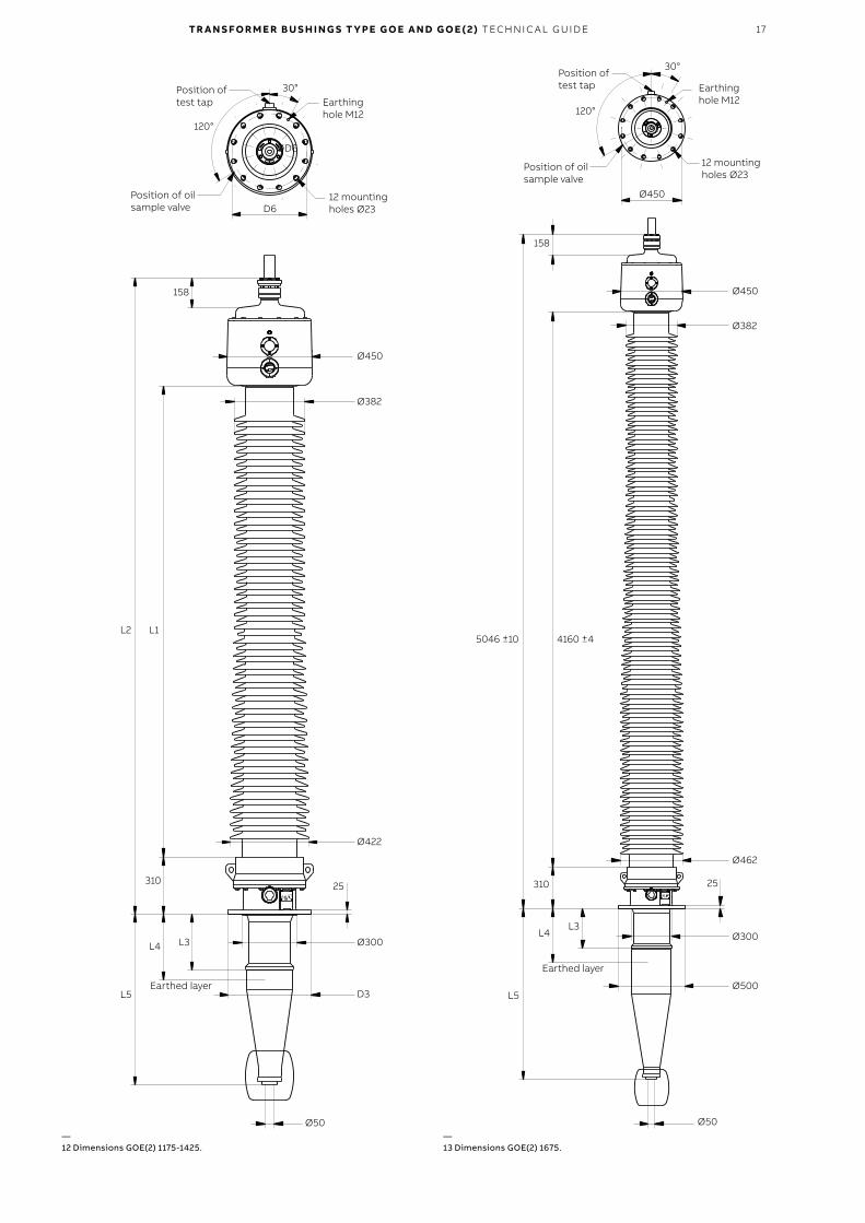
158
158
5046 ±10 4160 ±4
30°
30°Position of test tapPosition of
test tap
12 mounting holes Ø23
12 mounting holes Ø23
Earthing hole M12Earthing
hole M12
Position of oil sample valve
Position of oil sample valve
120°
120°
Ø450
ØD6
Ø450
Ø450
Ø462
Ø422
Ø300Ø300
Ø500D3
Ø50Ø50
2525 310310
L3
L3L4
L4
L5L5
Earthed layer
Earthed layer
Ø382
Ø382
L1
D6
L2
—12 Dimensions GOE(2) 1175-1425.
—13 Dimensions GOE(2) 1675.
18 TR A N S FO R M E R B U S H I N G S T Y PE G O E A N D G O E ( 2) TEC H N I C A L G U ID E
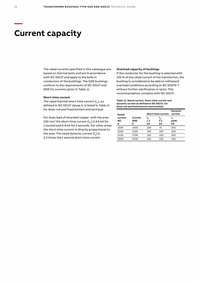
The rated currents specified in this catalogue are based on thermal tests and are in accordance with IEC 60137 and apply to the built-in conductors of the bushings. The GOE bushings conform to the requirements of IEC 60137 and IEEE for currents given in Table 11.
Short-time currentThe rated thermal short-time current (Ith), as defined in IEC 60137 clause 5, is listed in Table 11 for draw rod and fixed bottom end terminal.
For draw lead of stranded copper with the area 100 mm2 the short-time current (Ith) is 9.6 kA for 1 second and 6.8 kA for 2 seconds. For other areas the short-time current is directly proportional to the area. The rated dynamic current (Id) is 2.5 times the 1 second short-time current.
Overload capacity of bushingsIf the conductor for the bushing is selected with 120 % of the rated current of the transformer, the bushing is considered to be able to withstand overload conditions according to IEC 60076-7 without further clarification or tests. This recommendation complies with IEC 60137.
Table 12. Rated current, short-time current and dynamic current as defined in IEC 60137, for draw rod and fixed bottom end terminal.
Rated currentIECA
CurrentIEEEA
Short-time currentDynamic current
Ith
1 skA
Ith
2 skA
Id
peakkA
1600 1450 100 75 250
2500 2100 100 100 250
3150 2700 100 100 250
5000 4250 100 100 250
—Current capacity
TR A N S FO R M E R B U S H I N G S T Y PE G O E A N D G O E ( 2) TEC H N I C A L G U ID E 19
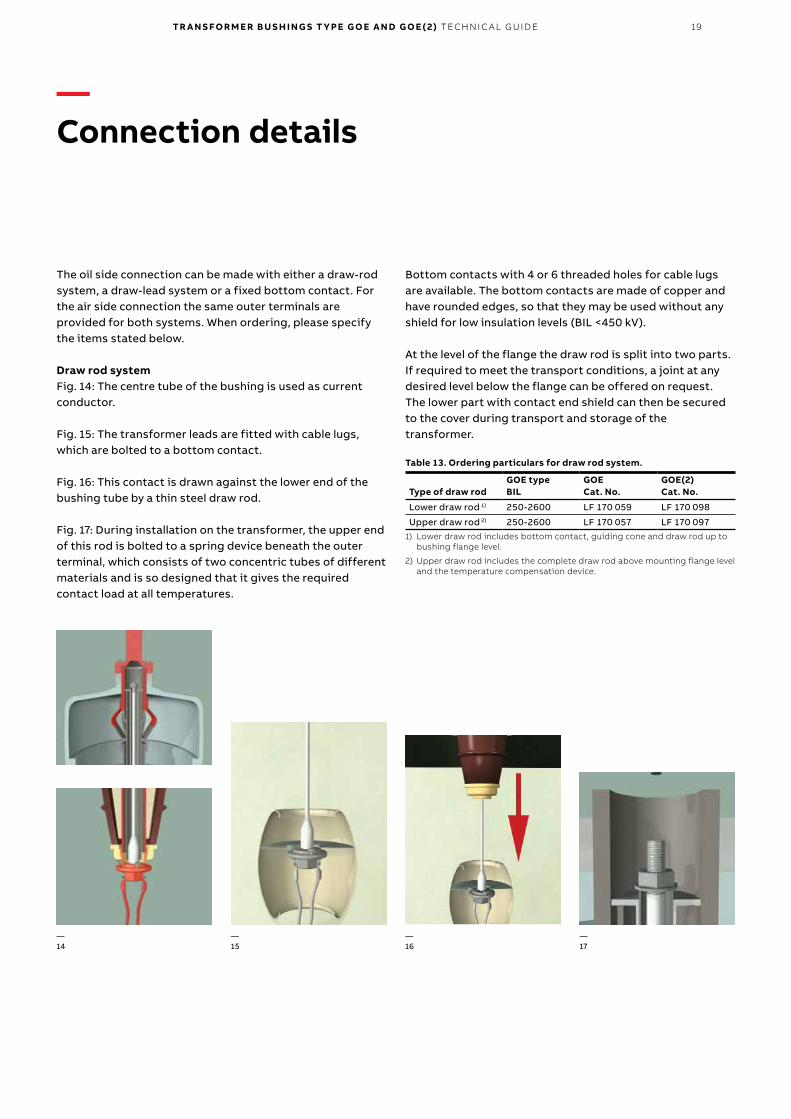
The oil side connection can be made with either a draw-rod system, a draw-lead system or a fixed bottom contact. For the air side connection the same outer terminals are provided for both systems. When ordering, please specify the items stated below.
Draw rod systemFig. 14: The centre tube of the bushing is used as current conductor.
Fig. 15: The transformer leads are fitted with cable lugs, which are bolted to a bottom contact.
Fig. 16: This contact is drawn against the lower end of the bushing tube by a thin steel draw rod.
Fig. 17: During installation on the transformer, the upper end of this rod is bolted to a spring device beneath the outer terminal, which consists of two concentric tubes of different materials and is so designed that it gives the required contact load at all temperatures.
Bottom contacts with 4 or 6 threaded holes for cable lugs are available. The bottom contacts are made of copper and have rounded edges, so that they may be used without any shield for low insulation levels (BIL <450 kV).
At the level of the flange the draw rod is split into two parts. If required to meet the transport conditions, a joint at any desired level below the flange can be offered on request. The lower part with contact end shield can then be secured to the cover during transport and storage of the transformer.
Table 13. Ordering particulars for draw rod system.
Type of draw rodGOE typeBIL
GOECat. No.
GOE(2)Cat. No.
Lower draw rod 1) 250-2600 LF 170 059 LF 170 098
Upper draw rod 2) 250-2600 LF 170 057 LF 170 0971) Lower draw rod includes bottom contact, guiding cone and draw rod up to
bushing flange level.
2) Upper draw rod includes the complete draw rod above mounting flange level and the temperature compensation device.
—14
—15
—16
—17
—Connection details
20 TR A N S FO R M E R B U S H I N G S T Y PE G O E A N D G O E ( 2) TEC H N I C A L G U ID E
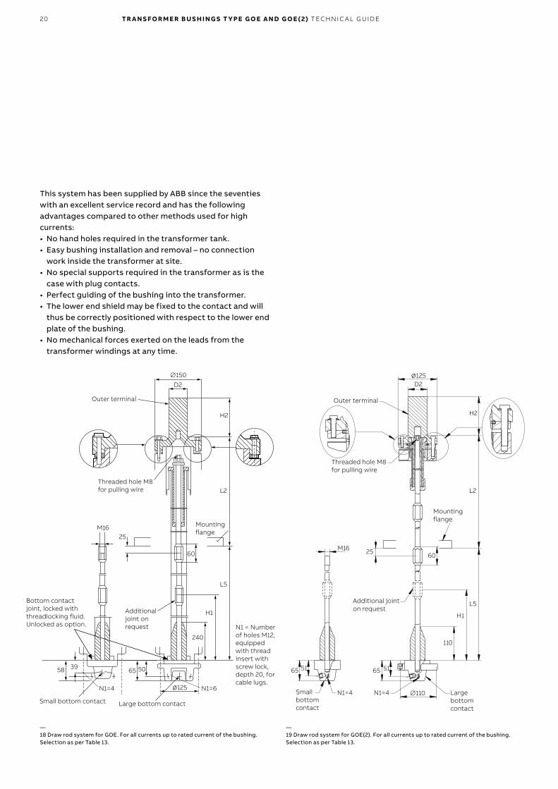
—19 Draw rod system for GOE(2). For all currents up to rated current of the bushing. Selection as per Table 13.
—18 Draw rod system for GOE. For all currents up to rated current of the bushing. Selection as per Table 13.
D2
∅150
Outer terminal
Threaded hole M8 for pulling wire
M1625
Additional joint on request
Mounting flange
L5
H2
L2
60
H1
240
D2∅125
Outer terminal
Threaded hole M8 for pulling wire
H2
L2
Mounting flange
M16 25 60
Additional joint on request
110
N1 = Number of holes M12, equipped with thread insert with screw lock, depth 20, for cable lugs.
∅125
5065
Large bottom contactSmall bottom contact
Bottom contact joint, locked with threadlocking fluid.Unlocked as option.
58 39
L5
H1
∅110
5165
N1=4
5165
Small bottom contact
Large bottom contact
N1=4N1=6N1=4
This system has been supplied by ABB since the seventies with an excellent service record and has the following advantages compared to other methods used for high currents:• No hand holes required in the transformer tank.• Easy bushing installation and removal – no connection
work inside the transformer at site.• No special supports required in the transformer as is the
case with plug contacts.• Perfect guiding of the bushing into the transformer.• The lower end shield may be fixed to the contact and will
thus be correctly positioned with respect to the lower end plate of the bushing.
• No mechanical forces exerted on the leads from the transformer windings at any time.
TR A N S FO R M E R B U S H I N G S T Y PE G O E A N D G O E ( 2) TEC H N I C A L G U ID E 21
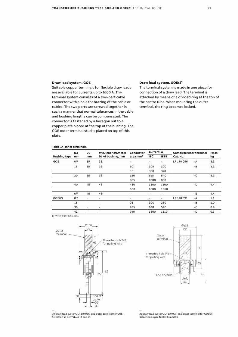
Draw lead system, GOESuitable copper terminals for flexible draw leads are available for currents up to 1600 A. The terminal system consists of a two-part cable connector with a hole for brazing of the cable or cables. The two parts are screwed together in such a manner that normal tolerances in the cable and bushing lengths can be compensated. The connector is fastened by a hexagon nut to a copper plate placed at the top of the bushing. The GOE outer terminal stud is placed on top of this plate.
—20 Draw lead system, LF 170 056, and outer terminal for GOE. Selection as per Tables 14 and 15.
—21 Draw lead system, LF 170 091, and outer terminal for GOE(2). Selection as per Tables 14 and 15.
D2∅150
Outer terminal
H2Threaded hole M8 for pulling wire
350L2
End of cable
D3D9
∅125
Outer terminal
H2
Threaded hole M8 for pulling wire
53
L2End of cableD3
46
D2
30
Draw lead system, GOE(2)The terminal system is made in one piece for connection of a draw lead. The terminal is attached by means of a divided ring at the top of the centre tube. When mounting the outer terminal, the ring becomes locked.
Table 14. Inner terminals.
Bushing typeD3mm
D9mm
Min. inner diameter D1 of bushing, mm
Conductor area mm2
Current, A Complete inner terminalCat. No.
MasskgIEC IEEE
GOE 0 1) 35 38 - - - LF 170 056 -A 3.2
15 35 38 50 205 200 -B 3.2
95 390 370
30 35 38 150 615 540 -C 3.2
285 1000 830
40 45 48 450 1300 1100 -D 4.4
600 1600 1360
0 1) 45 48 - - - -E 4.4
GOE(2) 0 1) - - - - - LF 170 091 -A 1.1
15 - - 95 300 260 -B 1.0
30 - - 285 630 540 -C 0.9
42 - - 740 1300 1110 -D 0.71) With pilot hole D=5
22 TR A N S FO R M E R B U S H I N G S T Y PE G O E A N D G O E ( 2) TEC H N I C A L G U ID E
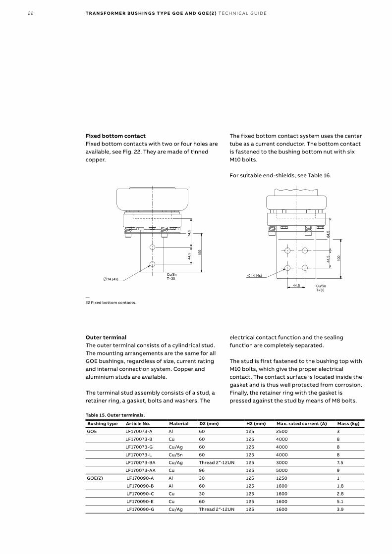
Fixed bottom contactFixed bottom contacts with two or four holes are available, see Fig. 22. They are made of tinned copper.
Table 15. Outer terminals.
Bushing type Article No. Material D2 (mm) H2 (mm) Max. rated current (A) Mass (kg)
GOE LF170073-A Al 60 125 2500 3
LF170073-B Cu 60 125 4000 8
LF170073-G Cu/Ag 60 125 4000 8
LF170073-L Cu/Sn 60 125 4000 8
LF170073-BA Cu/Ag Thread 2“-12UN 125 3000 7.5
LF170073-AA Cu 96 125 5000 9
GOE(2) LF170090-A Al 30 125 1250 1
LF170090-B Al 60 125 1600 1.8
LF170090-C Cu 30 125 1600 2.8
LF170090-E Cu 60 125 1600 5.1
LF170090-G Cu/Ag Thread 2“-12UN 125 1600 3.9
—22 Fixed bottom contacts.
The fixed bottom contact system uses the center tube as a current conductor. The bottom contact is fastened to the bushing bottom nut with six M10 bolts.
For suitable end-shields, see Table 16.
Outer terminalThe outer terminal consists of a cylindrical stud. The mounting arrangements are the same for all GOE bushings, regardless of size, current rating and internal connection system. Copper and aluminium studs are available.
The terminal stud assembly consists of a stud, a retainer ring, a gasket, bolts and washers. The
electrical contact function and the sealing function are completely separated.
The stud is first fastened to the bushing top with M10 bolts, which give the proper electrical contact. The contact surface is located inside the gasket and is thus well protected from corrosion. Finally, the retainer ring with the gasket is pressed against the stud by means of M8 bolts.
44,5
74,5
100
Cu/SnT=3014 (4x)
44,5
84,5
100
14 (4x)
44,5
Cu/SnT=30
TR A N S FO R M E R B U S H I N G S T Y PE G O E A N D G O E ( 2) TEC H N I C A L G U ID E 23
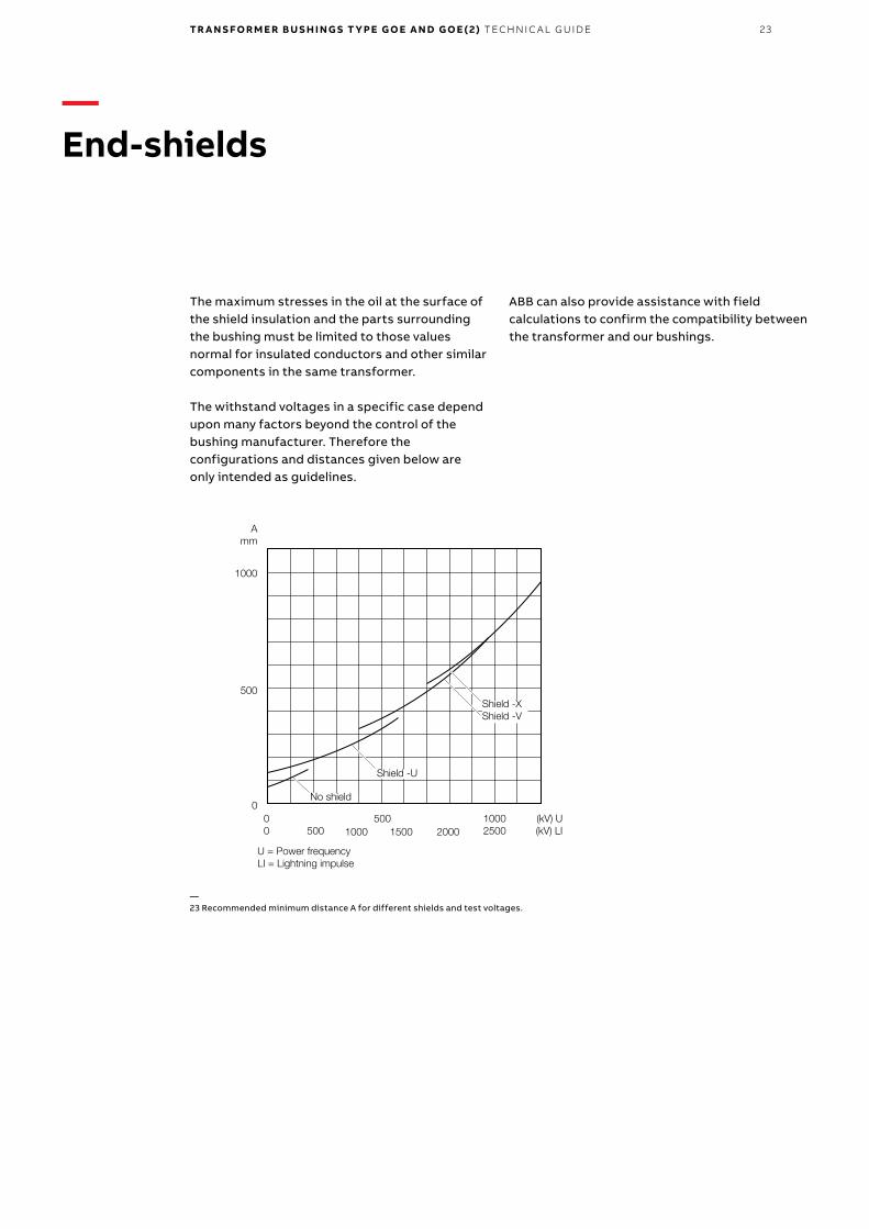
The maximum stresses in the oil at the surface of the shield insulation and the parts surrounding the bushing must be limited to those values normal for insulated conductors and other similar components in the same transformer.
The withstand voltages in a specific case depend upon many factors beyond the control of the bushing manufacturer. Therefore the configurations and distances given below are only intended as guidelines.
(kV) U(kV) LI
10002500
5001500 20001000500
00
0
500
1000
Amm
U = Power frequency LI = Lightning impulse
ABB can also provide assistance with field calculations to confirm the compatibility between the transformer and our bushings.
—End-shields
—23 Recommended minimum distance A for different shields and test voltages.
Shield -XShield -V
Shield -U
No shield
24 TR A N S FO R M E R B U S H I N G S T Y PE G O E A N D G O E ( 2) TEC H N I C A L G U ID E
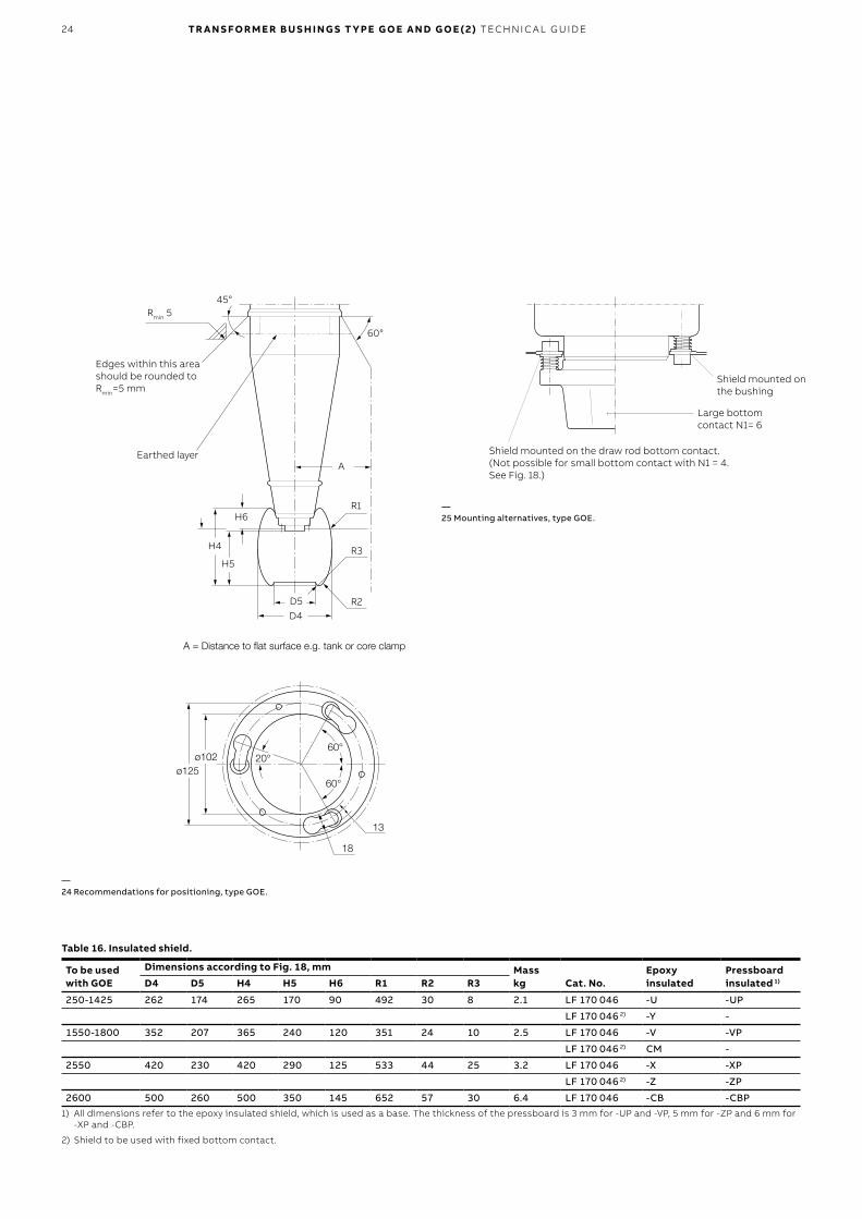
D4D5 R2
R3H5
H4
H6R1
Earthed layer
45°Rmin 5
Edges within this area should be rounded to Rmin=5 mm
60°
A
A = Distance to flat surface e.g. tank or core clamp
ø125ø102
60°20°
60°
13
18
Table 16. Insulated shield.
To be used with GOE
Dimensions according to Fig. 18, mm Masskg Cat. No.
Epoxy insulated
Pressboard insulated 1)D4 D5 H4 H5 H6 R1 R2 R3
250-1425 262 174 265 170 90 492 30 8 2.1 LF 170 046 -U -UP
LF 170 046 2) -Y -
1550-1800 352 207 365 240 120 351 24 10 2.5 LF 170 046 -V -VP
LF 170 046 2) CM -
2550 420 230 420 290 125 533 44 25 3.2 LF 170 046 -X -XP
LF 170 046 2) -Z -ZP
2600 500 260 500 350 145 652 57 30 6.4 LF 170 046 -CB -CBP1) All dimensions refer to the epoxy insulated shield, which is used as a base. The thickness of the pressboard is 3 mm for -UP and -VP, 5 mm for -ZP and 6 mm for
-XP and -CBP.
2) Shield to be used with fixed bottom contact.
—24 Recommendations for positioning, type GOE.
Shield mounted on the bushing
Shield mounted on the draw rod bottom contact. (Not possible for small bottom contact with N1 = 4. See Fig. 18.)
Large bottom contact N1= 6
—25 Mounting alternatives, type GOE.
TR A N S FO R M E R B U S H I N G S T Y PE G O E A N D G O E ( 2) TEC H N I C A L G U ID E 25
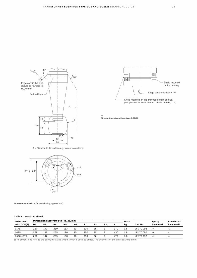
Shield mounted on the bushing
Shield mounted on the draw rod bottom contact. (Not possible for small bottom contact. See Fig. 19.)
Earthed layer
45°Rmin 5
Edges within this area should be rounded to Rmin=5 mm
60°
A = Distance to flat surface e.g. tank or core clamp
ø110 ø87
60°60°
Large bottom contact N1=4
ø13
ø18
R2R3
H5H4
H6 R1
D5D4
20°
—26 Recommendations for positioning, type GOE(2).
—27 Mounting alternatives, type GOE(2).
Table 17. Insulated shield.
To be used with GOE(2)
Dimensions according to Fig. 21, mm Masskg Cat. No.
Epoxy insulated
Pressboard insulated 1)D4 D5 H4 H5 H6 R1 R2 R3 A
1175 250 142 230 163 62 230 25 8 370 1.5 LF 170 092 -A -C
1425 258 142 265 180 80 350 32 9 430 1.8 LF 170 092 -K -L
1550-1675 258 142 265 180 80 350 32 9 470 1.8 LF 170 092 -K -L1) All dimensions refer to the epoxy insulated shield, which is used as a base. The thickness of the pressboard is 3 mm.
A
26 TR A N S FO R M E R B U S H I N G S T Y PE G O E A N D G O E ( 2) TEC H N I C A L G U ID E
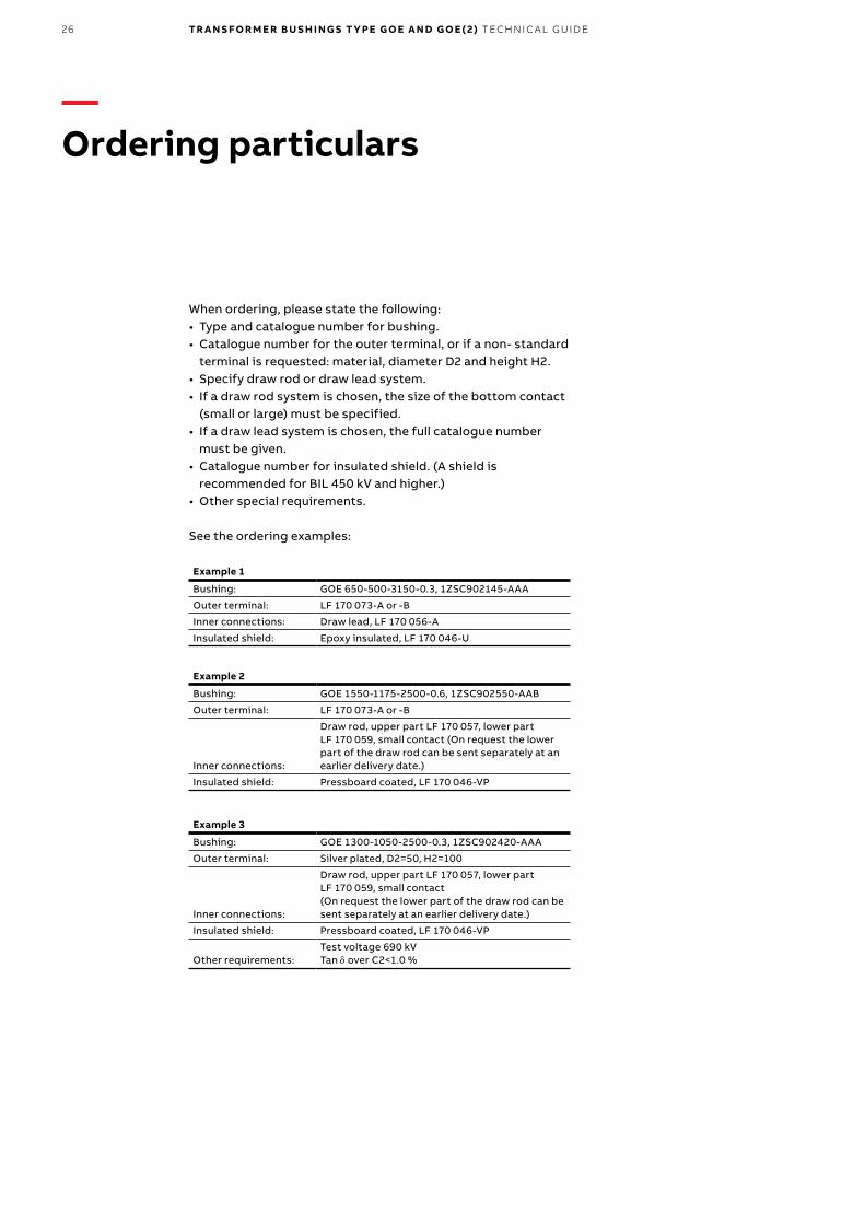
When ordering, please state the following:• Type and catalogue number for bushing.• Catalogue number for the outer terminal, or if a non- standard
terminal is requested: material, diameter D2 and height H2.• Specify draw rod or draw lead system.• If a draw rod system is chosen, the size of the bottom contact
(small or large) must be specified.• If a draw lead system is chosen, the full catalogue number
must be given.• Catalogue number for insulated shield. (A shield is
recommended for BIL 450 kV and higher.)• Other special requirements.
See the ordering examples:
Example 1
Bushing: GOE 650-500-3150-0.3, 1ZSC902145-AAA
Outer terminal: LF 170 073-A or -B
Inner connections: Draw lead, LF 170 056-A
Insulated shield: Epoxy insulated, LF 170 046-U
Example 2
Bushing: GOE 1550-1175-2500-0.6, 1ZSC902550-AAB
Outer terminal: LF 170 073-A or -B
Inner connections:
Draw rod, upper part LF 170 057, lower part LF 170 059, small contact (On request the lower part of the draw rod can be sent separately at an earlier delivery date.)
Insulated shield: Pressboard coated, LF 170 046-VP
Example 3
Bushing: GOE 1300-1050-2500-0.3, 1ZSC902420-AAA
Outer terminal: Silver plated, D2=50, H2=100
Inner connections:
Draw rod, upper part LF 170 057, lower part LF 170 059, small contact(On request the lower part of the draw rod can be sent separately at an earlier delivery date.)
Insulated shield: Pressboard coated, LF 170 046-VP
Other requirements:Test voltage 690 kVTan d over C2<1.0 %
—Ordering particulars
TR A N S FO R M E R B U S H I N G S T Y PE G O E A N D G O E ( 2) TEC H N I C A L G U ID E 27
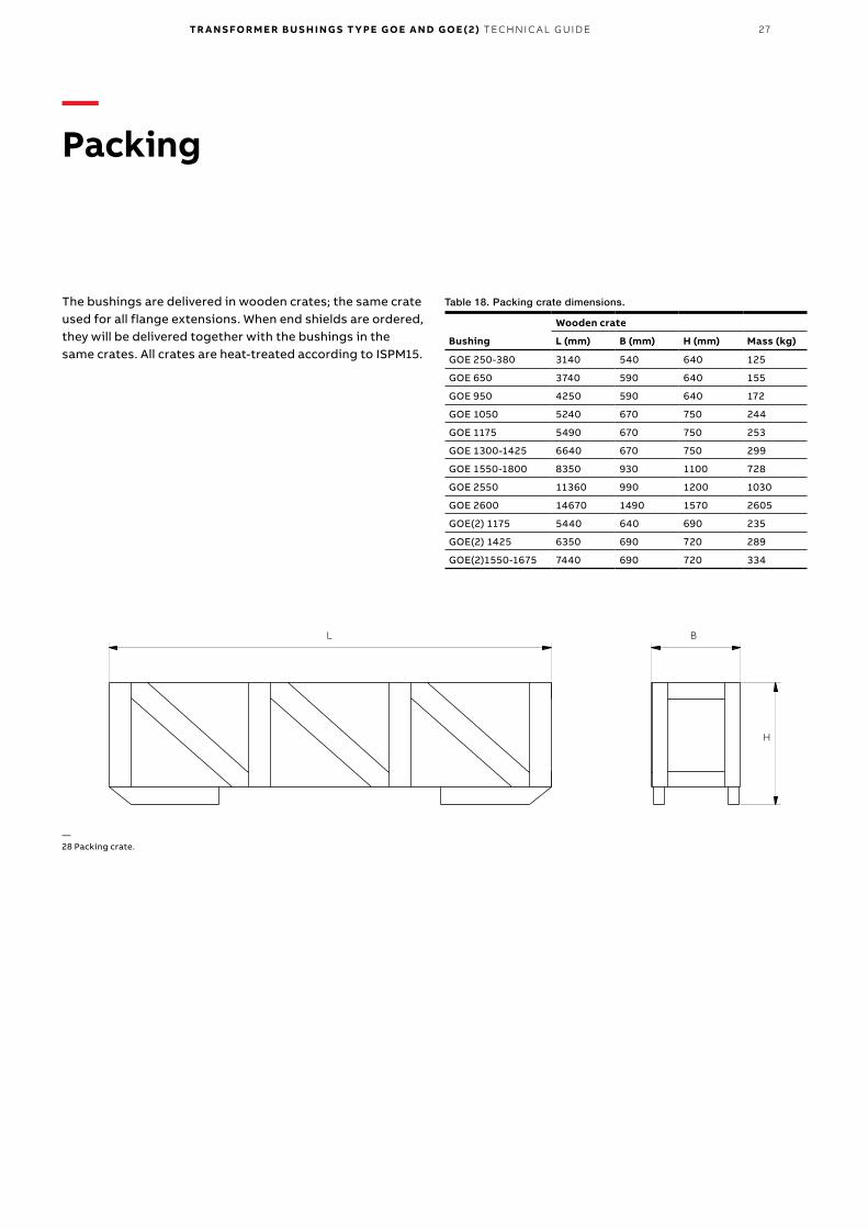
The bushings are delivered in wooden crates; the same crate used for all flange extensions. When end shields are ordered, they will be delivered together with the bushings in the same crates. All crates are heat-treated according to ISPM15.
Table 18. Packing crate dimensions.
Bushing
Wooden crate
L (mm) B (mm) H (mm) Mass (kg)
GOE 250-380 3140 540 640 125
GOE 650 3740 590 640 155
GOE 950 4250 590 640 172
GOE 1050 5240 670 750 244
GOE 1175 5490 670 750 253
GOE 1300-1425 6640 670 750 299
GOE 1550-1800 8350 930 1100 728
GOE 2550 11360 990 1200 1030
GOE 2600 14670 1490 1570 2605
GOE(2) 1175 5440 640 690 235
GOE(2) 1425 6350 690 720 289
GOE(2)1550-1675 7440 690 720 334
L B
H
—Packing
—28 Packing crate.
28 TR A N S FO R M E R B U S H I N G S T Y PE G O E A N D G O E ( 2) TEC H N I C A L G U ID E
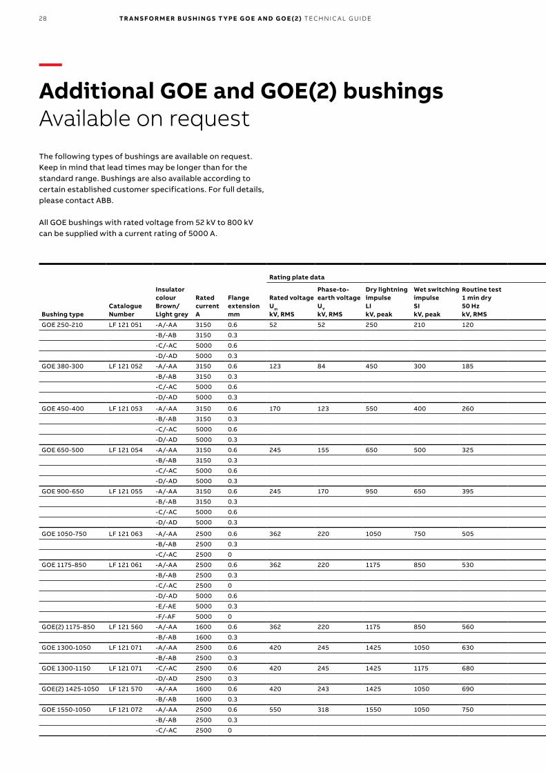
The following types of bushings are available on request. Keep in mind that lead times may be longer than for the standard range. Bushings are also available according to certain established customer specifications. For full details, please contact ABB.
All GOE bushings with rated voltage from 52 kV to 800 kV can be supplied with a current rating of 5000 A.
Bushing typeCatalogue Number
Insulator colourBrown/Light grey
Rated currentA
Flange extensionmm
Rating plate data Other data for information
Max. test load 1 min acc. to IEC 60137 (N)
Max permitted load (N) in operation at mounting angle
Dimensions(Fig. 28)
Rated voltageUm
kV, RMS
Phase-to-earth voltageUY
kV, RMS
Dry lightning impulseLIkV, peak
Wet switching impulseSIkV, peak
Routine test 1 min dry50 HzkV, RMS
Wet power frequencyACkV, RMS
Dry switching impulsekV, peak
Nominal capacitance between conductor and test tap (C1)C1±10% (pF) 0° -30° -60°
L2mm
L5mm
Creepage distancemm
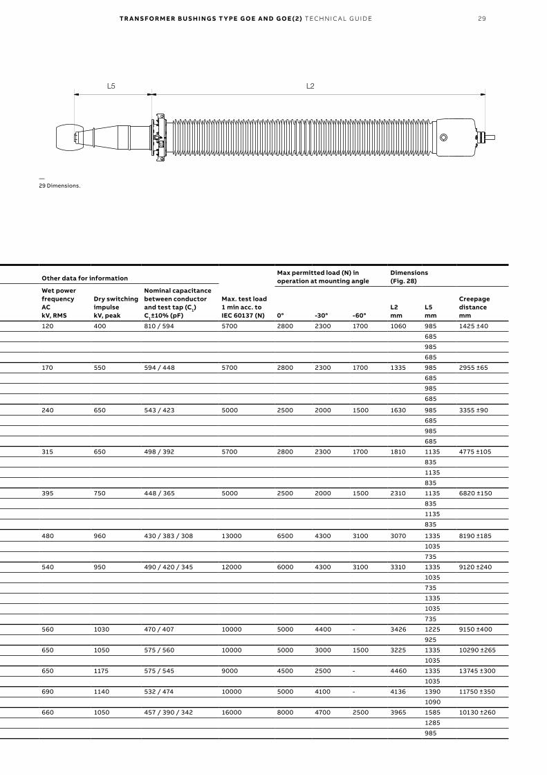
GOE 250-210 LF 121 051 -A/-AA 3150 0.6 52 52 250 210 120 120 400 810 / 594 5700 2800 2300 1700 1060 985 1425 ±40
-B/-AB 3150 0.3 685
-C/-AC 5000 0.6 985
-D/-AD 5000 0.3 685
GOE 380-300 LF 121 052 -A/-AA 3150 0.6 123 84 450 300 185 170 550 594 / 448 5700 2800 2300 1700 1335 985 2955 ±65
-B/-AB 3150 0.3 685
-C/-AC 5000 0.6 985
-D/-AD 5000 0.3 685
GOE 450-400 LF 121 053 -A/-AA 3150 0.6 170 123 550 400 260 240 650 543 / 423 5000 2500 2000 1500 1630 985 3355 ±90
-B/-AB 3150 0.3 685
-C/-AC 5000 0.6 985
-D/-AD 5000 0.3 685
GOE 650-500 LF 121 054 -A/-AA 3150 0.6 245 155 650 500 325 315 650 498 / 392 5700 2800 2300 1700 1810 1135 4775 ±105
-B/-AB 3150 0.3 835
-C/-AC 5000 0.6 1135
-D/-AD 5000 0.3 835
GOE 900-650 LF 121 055 -A/-AA 3150 0.6 245 170 950 650 395 395 750 448 / 365 5000 2500 2000 1500 2310 1135 6820 ±150
-B/-AB 3150 0.3 835
-C/-AC 5000 0.6 1135
-D/-AD 5000 0.3 835
GOE 1050-750 LF 121 063 -A/-AA 2500 0.6 362 220 1050 750 505 480 960 430 / 383 / 308 13000 6500 4300 3100 3070 1335 8190 ±185
-B/-AB 2500 0.3 1035
-C/-AC 2500 0 735
GOE 1175-850 LF 121 061 -A/-AA 2500 0.6 362 220 1175 850 530 540 950 490 / 420 / 345 12000 6000 4300 3100 3310 1335 9120 ±240
-B/-AB 2500 0.3 1035
-C/-AC 2500 0 735
-D/-AD 5000 0.6 1335
-E/-AE 5000 0.3 1035
-F/-AF 5000 0 735
GOE(2) 1175-850 LF 121 560 -A/-AA 1600 0.6 362 220 1175 850 560 560 1030 470 / 407 10000 5000 4400 - 3426 1225 9150 ±400
-B/-AB 1600 0.3 925
GOE 1300-1050 LF 121 071 -A/-AA 2500 0.6 420 245 1425 1050 630 650 1050 575 / 560 10000 5000 3000 1500 3225 1335 10290 ±265
-B/-AB 2500 0.3 1035
GOE 1300-1150 LF 121 071 -C/-AC 2500 0.6 420 245 1425 1175 680 650 1175 575 / 545 9000 4500 2500 - 4460 1335 13745 ±300
-D/-AD 2500 0.3 1035
GOE(2) 1425-1050 LF 121 570 -A/-AA 1600 0.6 420 243 1425 1050 690 690 1140 532 / 474 10000 5000 4100 - 4136 1390 11750 ±350
-B/-AB 1600 0.3 1090
GOE 1550-1050 LF 121 072 -A/-AA 2500 0.6 550 318 1550 1050 750 660 1050 457 / 390 / 342 16000 8000 4700 2500 3965 1585 10130 ±260
-B/-AB 2500 0.3 1285
-C/-AC 2500 0 985
—Additional GOE and GOE(2) bushingsAvailable on request
TR A N S FO R M E R B U S H I N G S T Y PE G O E A N D G O E ( 2) TEC H N I C A L G U ID E 29
L2L5
Bushing typeCatalogue Number
Insulator colourBrown/Light grey
Rated currentA
Flange extensionmm
Rating plate data Other data for information
Max. test load 1 min acc. to IEC 60137 (N)
Max permitted load (N) in operation at mounting angle
Dimensions(Fig. 28)
Rated voltageUm
kV, RMS
Phase-to-earth voltageUY
kV, RMS
Dry lightning impulseLIkV, peak
Wet switching impulseSIkV, peak
Routine test 1 min dry50 HzkV, RMS
Wet power frequencyACkV, RMS
Dry switching impulsekV, peak
Nominal capacitance between conductor and test tap (C1)C1±10% (pF) 0° -30° -60°
L2mm
L5mm
Creepage distancemm
GOE 250-210 LF 121 051 -A/-AA 3150 0.6 52 52 250 210 120 120 400 810 / 594 5700 2800 2300 1700 1060 985 1425 ±40
-B/-AB 3150 0.3 685
-C/-AC 5000 0.6 985
-D/-AD 5000 0.3 685
GOE 380-300 LF 121 052 -A/-AA 3150 0.6 123 84 450 300 185 170 550 594 / 448 5700 2800 2300 1700 1335 985 2955 ±65
-B/-AB 3150 0.3 685
-C/-AC 5000 0.6 985
-D/-AD 5000 0.3 685
GOE 450-400 LF 121 053 -A/-AA 3150 0.6 170 123 550 400 260 240 650 543 / 423 5000 2500 2000 1500 1630 985 3355 ±90
-B/-AB 3150 0.3 685
-C/-AC 5000 0.6 985
-D/-AD 5000 0.3 685
GOE 650-500 LF 121 054 -A/-AA 3150 0.6 245 155 650 500 325 315 650 498 / 392 5700 2800 2300 1700 1810 1135 4775 ±105
-B/-AB 3150 0.3 835
-C/-AC 5000 0.6 1135
-D/-AD 5000 0.3 835
GOE 900-650 LF 121 055 -A/-AA 3150 0.6 245 170 950 650 395 395 750 448 / 365 5000 2500 2000 1500 2310 1135 6820 ±150
-B/-AB 3150 0.3 835
-C/-AC 5000 0.6 1135
-D/-AD 5000 0.3 835
GOE 1050-750 LF 121 063 -A/-AA 2500 0.6 362 220 1050 750 505 480 960 430 / 383 / 308 13000 6500 4300 3100 3070 1335 8190 ±185
-B/-AB 2500 0.3 1035
-C/-AC 2500 0 735
GOE 1175-850 LF 121 061 -A/-AA 2500 0.6 362 220 1175 850 530 540 950 490 / 420 / 345 12000 6000 4300 3100 3310 1335 9120 ±240
-B/-AB 2500 0.3 1035
-C/-AC 2500 0 735
-D/-AD 5000 0.6 1335
-E/-AE 5000 0.3 1035
-F/-AF 5000 0 735
GOE(2) 1175-850 LF 121 560 -A/-AA 1600 0.6 362 220 1175 850 560 560 1030 470 / 407 10000 5000 4400 - 3426 1225 9150 ±400
-B/-AB 1600 0.3 925
GOE 1300-1050 LF 121 071 -A/-AA 2500 0.6 420 245 1425 1050 630 650 1050 575 / 560 10000 5000 3000 1500 3225 1335 10290 ±265
-B/-AB 2500 0.3 1035
GOE 1300-1150 LF 121 071 -C/-AC 2500 0.6 420 245 1425 1175 680 650 1175 575 / 545 9000 4500 2500 - 4460 1335 13745 ±300
-D/-AD 2500 0.3 1035
GOE(2) 1425-1050 LF 121 570 -A/-AA 1600 0.6 420 243 1425 1050 690 690 1140 532 / 474 10000 5000 4100 - 4136 1390 11750 ±350
-B/-AB 1600 0.3 1090
GOE 1550-1050 LF 121 072 -A/-AA 2500 0.6 550 318 1550 1050 750 660 1050 457 / 390 / 342 16000 8000 4700 2500 3965 1585 10130 ±260
-B/-AB 2500 0.3 1285
-C/-AC 2500 0 985
—29 Dimensions.
30 TR A N S FO R M E R B U S H I N G S T Y PE G O E A N D G O E ( 2) TEC H N I C A L G U ID E
Bushing typeCatalogue Number
Insulator colourBrown/Light grey
Rated currentA
Flange extensionmm
Rating plate data Other data for information
Max. test load 1 min acc. to IEC 60137 (N)
Max permitted load (N) in operation at mounting angle
Dimensions(Fig. 28)
Rated voltageUm
kV, RMS
Phase-to-earth voltageUY
kV, RMS
Dry lightning impulseLIkV, peak
Wet switching impulseSIkV, peak
Routine test 1 min dry50 HzkV, RMS
Wet power frequencyACkV, RMS
Dry switching impulsekV, peak
Nominal capacitance between conductor and test tap (C1)C1±10% (pF) 0° -30° -60°
L2mm
L5mm
Creepage distancemm
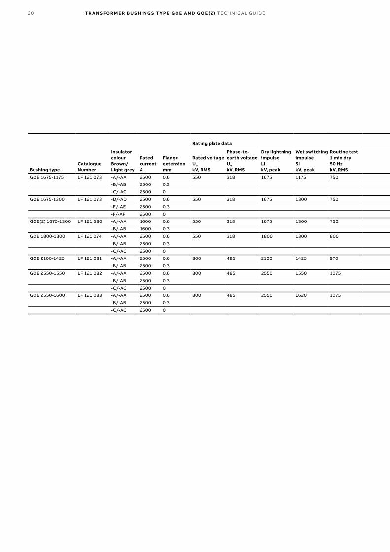
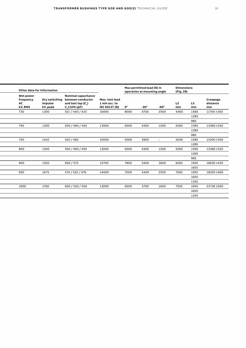
GOE 1675-1175 LF 121 073 -A/-AA 2500 0.6 550 318 1675 1175 750 730 1300 521 / 440 / 433 16000 8000 4700 2500 4460 1585 11700 ±300
-B/-AB 2500 0.3 1285
-C/-AC 2500 0 985
GOE 1675-1300 LF 121 073 -D/-AD 2500 0.6 550 318 1675 1300 750 790 1300 500 / 490 / 450 13000 6500 4300 1500 5260 1585 13380 ±330
-E/-AE 2500 0.3 1285
-F/-AF 2500 0 985
GOE(2) 1675-1300 LF 121 580 -A/-AA 1600 0.6 550 318 1675 1300 750 750 1410 525 / 482 10000 5000 3900 - 5046 1585 15200 ±350
-B/-AB 1600 0.3 1285
GOE 1800-1300 LF 121 074 -A/-AA 2500 0.6 550 318 1800 1300 800 800 1300 500 / 490 / 450 13000 6500 4300 1500 5260 1585 13380 ±330
-B/-AB 2500 0.3 1285
-C/-AC 2500 0 985
GOE 2100-1425 LF 121 081 -A/-AA 2500 0.6 800 485 2100 1425 970 900 1550 600 / 575 15700 7850 5400 3600 6265 1955 16630 ±420
-B/-AB 2500 0.3 1655
GOE 2550-1550 LF 121 082 -A/-AA 2500 0.6 800 485 2550 1550 1075 950 1675 574 / 522 / 476 14000 7000 4400 2500 7065 1955 18320 ±460
-B/-AB 2500 0.3 1655
-C/-AC 2500 0 1355
GOE 2550-1600 LF 121 083 -A/-AA 2500 0.6 800 485 2550 1620 1075 1000 1760 600 / 550 / 506 13000 6500 3700 1600 7555 1955 23736 ±500
-B/-AB 2500 0.3 1655
-C/-AC 2500 0 1355
TR A N S FO R M E R B U S H I N G S T Y PE G O E A N D G O E ( 2) TEC H N I C A L G U ID E 31
Bushing typeCatalogue Number
Insulator colourBrown/Light grey
Rated currentA
Flange extensionmm
Rating plate data Other data for information
Max. test load 1 min acc. to IEC 60137 (N)
Max permitted load (N) in operation at mounting angle
Dimensions(Fig. 28)
Rated voltageUm
kV, RMS
Phase-to-earth voltageUY
kV, RMS
Dry lightning impulseLIkV, peak
Wet switching impulseSIkV, peak
Routine test 1 min dry50 HzkV, RMS
Wet power frequencyACkV, RMS
Dry switching impulsekV, peak
Nominal capacitance between conductor and test tap (C1)C1±10% (pF) 0° -30° -60°
L2mm
L5mm
Creepage distancemm
GOE 1675-1175 LF 121 073 -A/-AA 2500 0.6 550 318 1675 1175 750 730 1300 521 / 440 / 433 16000 8000 4700 2500 4460 1585 11700 ±300
-B/-AB 2500 0.3 1285
-C/-AC 2500 0 985
GOE 1675-1300 LF 121 073 -D/-AD 2500 0.6 550 318 1675 1300 750 790 1300 500 / 490 / 450 13000 6500 4300 1500 5260 1585 13380 ±330
-E/-AE 2500 0.3 1285
-F/-AF 2500 0 985
GOE(2) 1675-1300 LF 121 580 -A/-AA 1600 0.6 550 318 1675 1300 750 750 1410 525 / 482 10000 5000 3900 - 5046 1585 15200 ±350
-B/-AB 1600 0.3 1285
GOE 1800-1300 LF 121 074 -A/-AA 2500 0.6 550 318 1800 1300 800 800 1300 500 / 490 / 450 13000 6500 4300 1500 5260 1585 13380 ±330
-B/-AB 2500 0.3 1285
-C/-AC 2500 0 985
GOE 2100-1425 LF 121 081 -A/-AA 2500 0.6 800 485 2100 1425 970 900 1550 600 / 575 15700 7850 5400 3600 6265 1955 16630 ±420
-B/-AB 2500 0.3 1655
GOE 2550-1550 LF 121 082 -A/-AA 2500 0.6 800 485 2550 1550 1075 950 1675 574 / 522 / 476 14000 7000 4400 2500 7065 1955 18320 ±460
-B/-AB 2500 0.3 1655
-C/-AC 2500 0 1355
GOE 2550-1600 LF 121 083 -A/-AA 2500 0.6 800 485 2550 1620 1075 1000 1760 600 / 550 / 506 13000 6500 3700 1600 7555 1955 23736 ±500
-B/-AB 2500 0.3 1655
-C/-AC 2500 0 1355


—ABB AB, ComponentsSE-771 80 LudvikaSwedenE-mail: [email protected]
www.abb.com/transformercomponents
1ZS
E 2
750
-10
5 en
, Rev
. 9, 2
019
-04
-30
© Copyright 2019 ABB. All rights reserved. Specifications subject to change without notice.


![Y ioG:o= /] E/GoE](https://img.pdfslide.net/doc/110x75/616a15bd11a7b741a34ea38a/y-iogo-egoe.jpg)
