Embed Size (px)
Citation preview

Issue 12/2015
g
Technical Data
Transformer-Monitoring
Relay
Model REG-DM
1 Wall-mounting housing
1 Panel-mounting housing
1 Plug-in module
1. Application
Power transformers are key components of an electrical
supply grid. The failure of a transformer not only has major
economic consequences for the energy supplier, it can also
lead to serious losses for consumers. For this reason, it
makes sense to monitor the transformer as intimately as
possible, to take its "temperature curve" (the thermal
image) so as to collect information about the current load
and the expected remaining life. This task can - based on IEC
standards - be solved by electronic measuring and
computing facilities.
The winding's hot-spot temperature is determined by the
current that runs through the windings and the oil
temperature, which can be fed into the REG-DM as an mA
signal or directly as a PT 100 signal. Appropriate input
modules are available for both signal forms. The appropriate
analogue channels must be available in order to record the
fill levels and other quantities such as the humidity or the
oil's gases (H2, CO, CO2, CH4, C2H2, C2H4, C2H6 ) content.
Monitoring consists of acquiring the transformer's main
parameters. For instance, the oil temperature is recorded in
addition to the current. Further, the hot-spot temperature
is determined from the oil temperature and the current in
accordance with IEC 60354 or IEC 60076 and extrapolated to
the transformer's service life consumption. Depending on
the oil or winding temperature, up to six cooling stages can
be activated. The system monitors the operating times of
the fans and controls the individual fan groups so that an
operating time as balanced as possible is achieved over the
whole operating life. If desired, individual fans can also be
permanently assigned to a certain cooling stage. Additional
alarms such as Buchholz pre-warning and/or Buchholz
triggering can be fed into the controller as digital signals,
displayed and sent to a SCADA system for further
processing.
The following protocols are available for transmission to
process control equipment (SCADA):
0 IEC 60870-5-101
0 IEC 60870-5-103
0 IEC 60870-5-104
0 DNP 3.0 (serial and over Ethernet)
0 IEC 61850
0 LON (on request)
0 MODBUS RTU / TCP
0 PROFIBUS
0 SPABUS

Transformer-Monitoring Relay REG-DM Page 2
Page 2
We take care of it.
2. REG-DM Characteristics 0 Large backlit LCD (128 x 128 pixels) with all important
data (temperatures, voltage etc.)
0 Measurement functions (U, I, P, Q, S, cos ϕ, ϕ, I*sin ϕ, f, Temp. )
0 Basic recorder function (3-channel line recorder)
0 Additional recorder with 4 x 64 channels and 108 MB repository
0 Record operating hours for the transformer and the tap charger
0 Determine the switching load (I2t value) for the tap changer
0 Determine the hot-spot temperature for a maximum of three windings
0 Calculate the service life consumption
0 Evaluation of the moisture content in cellulose and the risk of bubble formation
0 Control up to six fan groups
0 Control a heater
0 Control up to two oil pumps
0 Record the run-time of the individual fan groups and oil pumps
0 Cyclical control of the fan groups (same operating times)
0 Smart fan control (control fans based on the predicted hot-spot temperature)
0 Record and monitor limit values for gas and water, as well as the oil's H2 and CO content
0 Overload prediction
0 16 freely programmable binary inputs (with extension modules up to 128)
0 9 freely programmable binary outputs (with extension modules up to 128)
0 Freely programmable analogue inputs or outputs (mA)
0 PT100 direct input
0 Limit-value monitoring for all measured quantities
0 Programmable rated U and I values
0 AE Toolbox parameterisation software to set parameters, program devices and view data, and to evaluate and archive data on the PC
0 Free programmability enables implementation of control tasks
0 RS485 (COM3) peripheral bus for additional interface modules (ANA-D, BIN-D, COM3/Modbus converter)
0 Modbus RTU Master; direct communication with sensors and devices that have a Modbus interface (COM3/Modbus converter)
3. Description
REG-DM functions (maximum configuration)
1 2 x current and 2 x voltage transducer
2 Analogue inputs, PT100 (optional)
3 Binary inputs
4 Input for resistance-coded tap-position indicator (optional)
5 Auxiliary voltage
6 Indicator and processing unit
7 Analogue outputs
8 Binary outputs
9 E-LAN connection (2 x RS485 with repeater function)
10 COM1, RS232
11 COM1-S, RS232 (can be used alternatively to COM1)
12 COM2, RS232
13 COM3, RS485
14 Status notification (relay)

Page 3
Page 3
Transformer-Monitoring Relay REG-DM
3.1 Transformer Monitoring The transformer's main parameters are acquired in monitoring mode. The oil temperature can be entered through a mA-signal or by entering it directly in PT100. The hot-spot temperature is determined in accordance with IEC 60354 and IEC 60076 and extrapolated to the transformer's remaining lifetime.
Fans can be switched in up to six groups as well as two oil pumps to regulate the temperature. The oil levels can be monitored and the operating hours of the fans and pumps counted.
The REG-DM comes with ability to read mA inputs. These inputs enable the oil temperature of a temperature transducer, for example, to be read as mA signal.
If other combinations are needed, for example, the temperature as PT100 direct connection or the hot-spot -temperature as an mA output, the desired combination can be selected from characteristic group 'E'.
REG-DM block diagram
3.2 Transducer mode The values of all relevant quantities of an equally or arbitrarily loaded three-wire three-phase system are calculated from the sample values and further displayed.
Measured quantities on the displays
Voltage Ueff Current Ieff Active power P Reactive power Q Apparent power S cos ϕ Phase angle ϕ Reactive current I*sinϕ Frequency f
All of the measured and calculated values can be transferred by analogue signal or through SCADA.

Transformer-Monitoring Relay REG-DM Page 4
Page 4
We take care of it.
3.3 Recorder mode (S1) The time-dependent progress of up to two selectable measured quantities is continuously displayed as a line chart. For this chart the time grid for the recording is adjustable. The measured quantities are recorded with the current date and time (time-stamped). This enables the data to be queried by date and/or time. The average storage duration for a channel is about six weeks.
The stored quantities can be displayed and viewed using the keyboard or the WinREG operating software with the RegView module.
Time grid dt 14 s, 1, 5, 10, 30, min / Division
Regardless of the selected time grid dt (feed rate), all of the measurements are stored in an adjustable time grid (standard=1 s).
Each second value represents the arithmetic mean of 10 measurements that were generated at 100 ms intervals.
Storage behaviour in the case of an overflow
Overwrite with FIFO (First In First Out)
Storage time (voltage)
< 18.7 days worst case on average > 1 month
3.4 Recorder mode (S2) Recorder mode S2 provides a total of 4 recorders, each
fitted with 64 channels. The recording interval can be set
separately for each recorder. The data can only be
parameterized and viewed through the A. Eberle Toolbox.
The stored values cannot be displayed on the REG-DM’s
screen.

Page 5
Page 5
Transformer-Monitoring Relay REG-DM
4. Technical specifications
Regulations and standards
0 IEC 61010-1 / EN 61010-1 0 CAN/CSA C22.2 No. 1010.1-92 0 IEC 60255-22-1 / EN 60255-22-1 0 IEC 61326-1 / EN 61326-1 0 IEC 60529 / EN 60529 0 IEC 60068-1 / EN 60068-1 0 IEC 60688 / EN 60688 0 IEC 61000-6-2 / EN 61000-6-2 0 IEC 61000-6-4 / EN 61000-6-4
8
0 IEC 61000-6-5 / EN 61000-6-5 (in preperation)
AC voltage inputs (UE)
Measuring voltage UE 0 ... 160 V
Shape of the curve sinusoidal
Frequency range 16....50....60....65 Hz
Internal consumption U2 / 100 k
Overload capacity 230 V AC continuous
AC input (IE)
Measuring current In 1 A / 5 A (hardware & software selectable)
Shape of the curve sinusoidal
Frequency range 16....50....60....65 Hz
Control range 0 ... In ... 2.1 In
Internal consumption 0.5 VA
Overload capacity 10 A continuous 30 A for 10 s 100 A for 1 s 500 A for 5 ms
Analogue inputs (AI)
Quantity See order specifications
Input range
Y1...Y2
-20 mA...0...20 mA Y1 and Y2 are programmable
Control limit ± 1.2 Y2
Voltage drop ≤ 1.5 V
Potential isolation Optocoupler
Common-mode rejection
> 80 dB
Series-mode rejection > 60 dB / Decade from 10 Hz
Overload capacity ≤ 50 mA continuous
Error limit 0.5%
The inputs can be continuously short-circuited or open. All inputs are galvanically isolated from all other circuits.
Analogue outputs (AO)
Quantity See order specifications
Output range
Y1...Y2
-20 mA...0...20 mA Y1 and Y2 programmable
Control limit ± 1.2 Y2
Potential isolation Optocoupler
Load range 0 ≤ R ≤ 8 V / Y2
Alternating component < 0.5% of Y2
The outputs can be continuously short-circuited or open-circuited. All outputs are galvanically isolated from all other circuits.
Temperature input PT100
Quantity up to three PT100 inputs are possible
Type of connection Three-wire circuit
Current through sensor < 8 mA
Potential isolation Optocoupler
Line compensation No compensation required
Transmission behaviour
linear
These inputs have an open circuit monitoring.
Resistance input (tap position potentiometer)
Quantity See order specifications
Connection Three-wire, convertible to four-wire
Total resistance in the resistor chain
R1: 2 kΩ
R3: 20 kΩ
Resistance per tap adjustable
R1: 5…100 Ω/tap
R3: 50…2000 Ω/tap
Number of taps ≤ 38
Potential isolation Optocoupler
Current through resistor chain
max. 25 mA
These inputs have an open circuit monitoring.
Binary inputs (BI)

Transformer-Monitoring Relay REG-DM Page 6
Page 6
We take care of it.
Binary inputs (BI)
Common Shape of the permissible curve
Rectangular, sinusoidal
Signal frequency DC, 40 ... 70 Hz Potential isolation Optocoupler; all inputs
galvanically isolated from each other
Anti-bounce filter Software filter, with 50Hz AC input filter
Characteristic D1 - Inputs E1 ... E8 Control signals Ust AC/DC
range 48 V ... 250 V
H - Level L - Level
≥ 48 V < 10 V
Input resistance 108 kΩ
Characteristic D1 - Inputs E9 ... E16 Control signals Ust AC/DC
range 10 V ... 50 V
H - Level L - Level
≥ 10 V < 5 V
Input resistance 6.8 kΩ
Characteristic D2 - Inputs E1 ... E16 Control signals Ust AC/DC
range 48 V ... 250 V,
H - Level L - Level
≥ 48 V < 10 V
Input resistance 108 kΩ
Characteristic D3 - Inputs E1 ... E16 Control signals Ust AC/DC
range 10 V ... 50 V
H - Level L - Level
≥ 10 V < 5 V
Input resistance 6.8 kΩ
Characteristic D4 - Inputs E1 ... E16 Control signals Ust AC/DC
range 80 V ... 250 V
H - Level L - Level
≥ 80 V < 40 V
Input resistance 108 kΩ
Characteristic D5 - Inputs E1 ... E16 Control signals Ust AC/DC
range 190 V ... 250 V
H - Level L - Level
≥ 176 V < 88 V
Input resistance 108 kΩ
Simplified diagram of a binary input
Binary outputs (BO)
max. switching frequency
≤ 1 Hz
Potential isolation Isolated from all internal device potentials
Contact load AC: 250 V, 5 A (cosϕ = 1.0) AC: 250 V, 3 A (cosϕ = 0.4)
Switching capacity max. 1250 VA DC: 30 V, 5 A resistive
DC: 30 V, 3.5 A L/R=7 ms
DC: 110 V, 0.5 A resistive
DC: 220 V, 0.3 A resistive
Switching capacity max. 150 W
Inrush current 250 V AC, 30 V DC
10 A for max. 4 s
Switching operations ≥ 5·105 electrical
Analog/Digital Conversion
Type 12 bit successive-approximation
A/D bit resolution +/- 11 bit
Sampling rate 24 samples per period, e.g. 1.2 kHz at a 50Hz signal *
*The measurement inputs are equipped with an Anti-Aliasing filter.
Real-time clock (RTC)
Accuracy +/- 20 ppm
Buffering Lithium button cell
Limit-value monitoring
Limit values programmable
Response times programmable
Alarm indicators LED programmable

Page 7
Page 7
Transformer-Monitoring Relay REG-DM
Measured quantities True RMS voltages U12, (U23, U31) (≤ 0.25%)
True RMS current I1, (I2 , I3) (≤ 0.25%)
Active power P (≤ 0.5%)
Reactive power Q (≤ 0.5%)
Apparent power S (≤ 0.5%)
Power factor cos ϕ (≤ 0.5%)
Phase angle ϕ (≤ 0.5%)
Reactive current I · sin ϕ (≤ 1%)
Frequency f (≤ 0.05%)
Reference conditions Reference temperature 23°C ± 1 K
Input quantities UE = 0 ... 160 V IE = 0 ... 1A / 0 ... 5A
Frequency 45 Hz...65 Hz
Shape of the curve Sinusoidal, form factor 1.1107
Load (only for characteristics
E91...E900) Rn = 5 V / Y2 ± 1%
Other IEC 60688 - Part 1
Electrical safety
Safety class I
Degree of pollution 2
Measurement category IV / 150 V
III / 300 V
Operating voltages
50 V 150 V 230 V
E-LAN, COM1 ... COM3, Analogue inputs, Analogue outputs, Inputs 10...50 V
Voltage inputs, current inputs
Auxiliary voltage, binary inputs, relay outputs, status
Electromagnetic compatibility EMC requirements EN 61326-1
Equipment class A Continuous, unmonitored operation, industrial location and EN 61000-6-2 and 61000-6-4
Interference emissions
Conducted and radiated emission
EN 61326 Table 3 EN 61000-6-4
Harmonic currents EN 61000-3-2
Voltage fluctuations and flicker
EN 61000-3-3
Disturbance immunity EN 61326 Table A1 and EN 61000-6-2
ESD IEC 61000-6-5 6 kV/8 kV contact/air
Electromagnetic field IEC 61000-4-3\80 – 2000 MHz: 10 V/m
Fast transient IEC 61000-4-4 4 kV/2 kV
Surge voltages IEC 61000-4-5 4 kV/2 kV
Conducted HF signals IEC 61000-4-6 150 kHz – 80 MHz: 10 V
Power-frequency magnetic fields
IEC 61000-4-8 100 A/m (50 Hz), continuous 1000 A/m (50 Hz), 1 s
Voltage dips IEC 61000-4-11 30% / 20 ms, 60% / 1 s
Voltage interruptions IEC 61000-4-11 100% / 5s
Damped oscillations IEC 61000-4-12, Class 3, 2.5 kV
Test voltages Description Test voltage / kV counter circuit*
Auxiliary voltage Uh 2.3 COMs, AI, AO
Auxiliary voltage Uh 2.3 BI, BO
Measuring voltage Ue 2.3 COMs, AI, AO
Measuring voltage Ue 3.3 Uh, BI, BO
Measuring voltage Ue 2.2 Ie
Measuring current Ie 2.3 COMs, AI, AO
Measuring current Ie 3.3 Uh, BI, BO
Interfaces, COMs COMs 2.3 BI, BO
Analogue outputs AO 2.3 BI, BO
Analogue outputs AO 0.5 COMs, AI
Analogue inputs AI 2.3 BI, BO
Analogue inputs AI 0.5 COMs, AO

Transformer-Monitoring Relay REG-DM Page 8
Page 8
We take care of it.
Test voltages Description Test voltage / kV counter circuit*
Binary inputs BI 2.3 BI
Binary inputs BI 2.3 BO
Binary outputs BO 2.3 BO
*Counter circuits are always at the rack potential. All test voltages are AC voltages in kV, which may be applied for 1 minute. The COM interfaces are tested against each other with 0.5 kV.
Auxiliary voltage
Characteristic H0 H1/H11 H2
AC (internal) 75…185 V - -
AC - 85 ... 264 V -
DC - 88 ... 280 V 18 ... 72 V
AC power consumption
≤ 35 VA ≤ 35 VA (H1) ≤ 45 VA (H11)
-
DC power consumption
- ≤ 25 W (H1) ≤ 35 W (H11)
≤ 25 W
Frequency 45 ... 400Hz 45 ... 400Hz -
Microfuse T1 250 V T1 250 V T2 250 V
The following applies to all characteristics: Voltage dips of ≤ 25 ms result neither in data loss nor malfunctions. Fuses are time lag (slow blow) type.
Ambient conditions
Temperature range
Function (Housing) Function (plug-in module) Transport and storage
-10 °C ... +50 °C -10 °C ... +60 °C -25 °C ... +65 °C
Dry cold IEC 60068-2-1, - 10°C / 16 h
Dry heat IEC 60068-2-2, + 55°C / 16 h
Humid heat constant
IEC 60068-2-78 + 40°C / 93% / 2 days
Humid heat cyclical
IEC 60068-2-30 12+12 h, 6 cycles +55°C / 93%
Drop and topple IEC 60068-2-31 100 mm drop height, unpackaged
Vibration IEC 60255-21-1, Class 1
Shock IEC 60255-21-2, Class 1
Earthquake resistance IEC 60255-21-3, Class 1
Display
LC - Display 128 x 128 graphic display
Back-lighting LED, automatic switch off after 15 minutes
Indicator elements (LEDs)
Color Quantity Freely programmable quantity
Green 1 --
Yellow 5 5
Red 2 2
Quantity without Manual/Auto and Local/Remote LEDs on the REG-DM
Storage
Firmware and recorder data characteristic S2
Flash memory
Device characteristics and calibration data
serial EEPROM with ≥ 1000 k write/read cycles
Other data and recorder data Characteristic S1
MRAM, Backup to flash memory possible
The backup battery on these devices is only used to buffer the real time clock if the aux. power supply is off.
5. Mechanical design
Plug-in module
Front panel Plastic, RAL 7035 grey on aluminium brackets
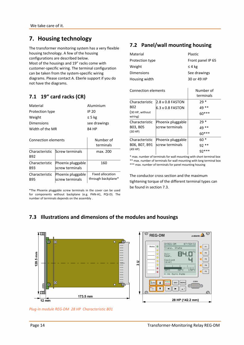
Height 3 U (132.5 mm)
Width 28 HP (142.2 mm)
Printed circuit board 160 mm x 100 mm
Weight ≤ 1.5 kg
Protection type
– Plug-in module – Female multipoint
connector
IP 00 IP 00
Mounting in conformity with DIN 41494 Part 5
Plug-in connector DIN 41612

Page 9
Page 9
Transformer-Monitoring Relay REG-DM
5.1 Position of the male or female
multipoint connectors
The male multipoint connectors are firmly connected to the device's printed circuit board, meaning that the female multipoint connectors must be mounted in specific positions in the housing or the module rack. A specific position number determines the reference point for the mounting of the guide holders and the connection elements on the back of the module rack/housing.
Position of the REG-DM female socket connectors
Position of the REG-DM male socket connectors
Position numbers
Socket connector
1 2 3 4 5 6
PCB card guide n - - - - n+26
Screws n n+4 n+8 n+11 n+16 n+25
5.2 Pin assignment of the REG-DM
Socket connector 1; (binary outputs)
Freely programmable 1 NCC + 1 NOC
R1 Pole Pole
b2 b4
NCC NOC
z2 z4
Freely programmable
1 NCC + 1 NOC
R2 Pole Pole
b8 b10
NCC NOC
Z8 z10
Freely programmable R3 Pole b14 NOC z14
Freely programmable R4 Pole b16 NOC z16
Freely programmable R5 Pole b20 NOC Z20
Manual/Auto (switch over)
Pole b22 Automatic Z22
Man b24
Status Pole b26 NOC/NCC Z24
Binary outputs (BO) 4 relays freely programmable
GND R6...R9 Z28
NOC R6 b30 NOC R8 Z30
NOC R7 b32 NOC R9 Z32
The status contact is either NOC or NCC based on characteristic U. This can be changed at a later stage by a soldered bridge.
Socket connector 2; (binary inputs) Characteristic D1
Freely programmable E1 + b2 - z2
Freely programmable E2 + b4 - z4
Freely programmable E3 + b6 - z6
Freely programmable E4 + b8 - z8
Freely programmable E5 + b10 - z10
Freely programmable E6 + b12 - z12
Freely programmable E7 + b14 - z14
Freely programmable E8 + b16 - z16
Freely programmable E9 + b24 - b32
Freely programmable E10 + b26 -
Freely programmable E11 + b28 -
Freely programmable E12 + b30 -
Freely programmable E13 + z24 - z32
Freely programmable E14 + z26 -
Freely programmable E15 + z28 -
Freely programmable E16 + z30 -

Transformer-Monitoring Relay REG-DM Page 10
Page 10
We take care of it.
Socket connector 2; (binary inputs) Characteristics D2...D5
Freely programmable E1 + b2 - z2
Freely programmable E2 + b4 - z4
Freely programmable E3 + b6 - z6
Freely programmable E4 + b8 - z8
Freely programmable E5 + b10 - z10
Freely programmable E6 + b12 - z12
Freely programmable E7 + b14 - z14
Freely programmable E8 + b16 - z16
Freely programmable E9 + b18 - z18
Freely programmable E10 + b20 - z20
Freely programmable E11 + b22 - z22
Freely programmable E12 + b24 - z24
Freely programmable E13 + b26 - z26
Freely programmable E14 + b28 - z28
Freely programmable E15 + b30 - z30
Freely programmable E16 + b32 - z32
All inputs are freely programmable.
Socket connector 3; (measuring voltage, auxiliary voltage)
DC output (max. 5 W) + 5V d2, b2, z2 GND d4, b4, z4
Measuring voltage U1 U1a 20 U1b** 22
Measuring voltage U2* U2a** 26 U2b 24
Auxiliary voltage UH L(+) 28 N(-) 30 PE 32
*only available for characteristics M2 and M9
**for characteristic M2 (ARON), pin 26 is internally connected to pin 22. The connection is L1 (pin 20), L2 (pin 22) and L3 (pin 24).
Socket connector 4; (alternating current input)
Measuring current IE1 s1 1 s2 2
Measuring current IE2* s1 3 s2 4
*only available for characteristics M2 or M9
The current measuring inputs are equipped with special male and female socket connectors that short-circuit the current transformer when they are
removed from the device. This means that the device does not have to be short-circuited externally.
Socket connector 4 is numbered from top to bottom (1 to 6). The contact with description 6 is at the top of the male socket connector in the REG-D for design
reasons. This means that the male socket connector is numbered 6 to 1 from top to bottom (embossing on the male socket connector).
Socket connector 5; (binary inputs) Characteristic X25
Freely programmable E17 + b2 - z2
Freely programmable E18 + b4 - z4
Freely programmable E19 + b6 - z6
Freely programmable E20 + b8 - z8
Freely programmable E21 + b10 - z10
Freely programmable E22 + b12 - z12
Freely programmable E23 + b14 - z14
Freely programmable E24 + b16 - z16
Freely programmable E25 + b24 - b32
Freely programmable E26 + b26 -
Freely programmable E27 + b28 -
Freely programmable E28 + b30 -
Freely programmable E29 + z24 - z32
Freely programmable E30 + z26 -
Freely programmable E31 + z28 -
Freely programmable E32 + z30 -
Socket connector 5; (binary inputs) Characteristics X15, 24,
28, 29
Freely programmable E17 + b2 - z2
Freely programmable E18 + b4 - z4
Freely programmable E19 + b6 - z6
Freely programmable E20 + b8 - z8
Freely programmable E21 + b10 - z10
Freely programmable E22 + b12 - z12
Freely programmable E23 + b14 - z14
Freely programmable E24 + b16 - z16
Freely programmable E25 + b18 - z18
Freely programmable E26 + b20 - z20
Freely programmable E27 + b22 - z22
Freely programmable E28 + b24 - z24
Freely programmable E29 + b26 - z26
Freely programmable E30 + b28 - z28
Freely programmable E31 + b30 - z30
Freely programmable E32 + b32 - z32

Page 11
Page 11
Transformer-Monitoring Relay REG-DM
Socket connector 5; (binary outputs) Characteristic X01
Relay 10
Freely programmable
Pole b2 NOC z2
NCC b4
Relay 11
Freely programmable
Pole b6 NOC z6
NCC b8
Relay 12
Freely programmable
Pole b10 NOC z10
NCC b12
Relay 13
Freely programmable
Pole b14 NOC z14
NCC b16
Relay 14
Freely programmable
Pole b18 NOC z18
NCC b20
Relay 15
Freely programmable
Pole b22 NOC z22
NCC b24
Relay 16
Freely programmable
Pole b26 NOC z26
NCC b28
Relay 17
Freely programmable
Pole b30 NOC z30
NCC b32
Socket connector 5; (SCADA interface) Characteristic XW1
COM1/RxD d2 COM1/GND b2 COM1/TxD z2
COM1/CTS d4 COM1/GND b4 COM1/RTS z4
COM1/GND Service/RxD*
d6 COM1/GND
Service/GND* b6
COM1/GND Service/TxD*
z6
Free Service/CTS*
d8 free
Service/GND* b8 free
Service/RTS* z8
CPU/PE d10 CPU/PE b10 CPU/PE z10
VCC/+5 V DC d12 VCC/+5 V DC b12 VCC/+5 V DC z12
GND/5 V DC d14 GND/5 V DC b14 GND/5 V DC z14
Fibre optic/ Rx
d16 free
GND* b16 Fibre optic/
Tx z16
Free d18 free b18 free z18
RS485/N (B) RS485/P(A)* d20
free
RS485 GND* b20
RS485/P (A) RTS485/N(B)* z20
RS485 GND d22 RS485 GND b22 RS485 GND z22
Free Modem/RxD*
d24 free
Modem/DTR* b24 free
Modem/TxD* z24
COM2/PE Modem/CTS*
d26 COM2/PE
Modem/DSR* b26 COM2/PE
Modem/RTS* z26
Free Modem/GND*
d28 free
Modem/RI* b28 free
Modem/DCD* z28
COM2/RxD d30 COM2/GND b30 COM2/TxD z30
COM2/CTS d32 COM2/GND b32 COM2/RTS z32 *different allocation for Modbus (XZ23) and SpaBus (XZ22)
REG-DM CPU and the SCADA interface communicate through the COM2 interface.
Communication with the control system can take place optionally through fibre optic cable, RS485 or RS232 (COM1). The fibre optic cable requires a separate module. The SCADA connection module for Modbus (XZ23) and Spabus (XZ22) is configured through the service interface. This means that it also has to be wired.
Socket connector 6; (analogue inputs and outputs;
interfaces)
Free
d2 Analogue channel 1
+
b2 Analogue channel 2
+
z2
DCF GND
d4 Analogue channel 1
-
b4 Analogue channel 2
-
z4
DCF EA+ d6 E-LAN left
EA +
b6 E-LAN right
EA +
z6
DCF EA- d8 E-LAN left
EA -
b8 E-LAN right
EA -
z8
E-LAN left GND
d10 E-LAN left
E +
b10 E-LAN right
E +
z10
E-LAN right
GND
d12 E-LAN left E -
b12 E-LAN right
E -
z12
Free
d14 Analogue channel 3
+
b14 Analogue channel 4
+
z14
COM1-S
TxD
d16 Analogue channel 3
-
b16 Analogue channel 4
-
z16
COM1-S
RTS
d18 free b18 free z18
COM1-S
GND
d20 COM2 TxD b20 COM2 RTS z20
COM1-S
RxD
d22 COM2 RxD b22 COM2 CTS z22
COM1-S
CTS
d24 COM2 GND b24 free z24
Free
d26 Analogue channel 5
+
b26 Analogue channel 6
+
z26
Free
d28 Analogue channel 5
-
b28 Analogue channel 6
-
z28
Free d30 COM3 Tx + b30 COM3 Rx + z30
COM3 GND d32 COM3 TX- b32 COM3 Rx - z32

Transformer-Monitoring Relay REG-DM Page 12
Page 12
We take care of it.
6. Block diagrams
Block diagram REG-DM Characteristic D1

Page 13
Page 13
Transformer-Monitoring Relay REG-DM
Block diagram REG-DM Characteristic D2 / D3 / D4 / D5
Transformer-Monitoring Relay REG-DM Page 14
Page 14
We take care of it.
7. Housing technology
The transformer monitoring system has a very flexible housing technology. A few of the housing configurations are described below. Most of the housings and 19” racks come with customer-specific wiring. The terminal configuration can be taken from the system-specific wiring diagrams. Please contact A. Eberle support if you do not have the diagrams.
7.1 19“ card racks (CR)
Material Aluminium
Protection type IP 20
Weight ≤ 5 kg
Dimensions see drawings
Width of the MR 84 HP
Connection elements Number of terminals
Characteristic B92
Screw terminals max. 200
Characteristic B93
Phoenix pluggable screw terminals
160
Characteristic B95
Phoenix pluggable screw terminals
Fixed allocation through backplane*
*The Phoenix pluggable screw terminals in the cover can be used for components without backplane (e.g. PAN-A1, PQI-D). The number of terminals depends on the assembly .
7.2 Panel/wall mounting housing
Material Plastic
Protection type Front panel IP 65
Weight ≤ 4 kg
Dimensions See drawings
Housing width 30 or 49 HP
Connection elements Number of terminals
Characteristic B02 (30 HP, without
wiring)
2.8 x 0.8 FASTON
6.3 x 0.8 FASTON
29 *
49 **
60***
Characteristic B03, B05
(30 HP)
Phoenix pluggable screw terminals
29 *
49 **
60***
Characteristic B06, B07, B91 (49 HP)
Phoenix pluggable screw terminals
60 *
92 **
92*** * max. number of terminals for wall mounting with short terminal box ** max. number of terminals for wall mounting with long terminal box *** max. number of terminals for panel mounting housing
The conductor cross section and the maximum
tightening torque of the different terminal types can
be found in section 7.3.
7.3 Illustrations and dimensions of the modules and housings
Plug-in module REG-DM 28 HP Characteristic B01

Page 15
Page 15
Transformer-Monitoring Relay REG-DM
Conductor cross section and torque of the terminals
connector, pitch, application example
cross section / mm2 torque
stranded solid Nm
10 poles, 7.62 mm, measurements , aux. voltage
4 4 0,6
16 poles, 5 mm, BIs, relays 2,5 2,5 0,6
4/5 poles, 3.81 mm, additional functions, COMs
1,5 1,5 0,25
Panel mounting housing 30 HP - Characteristic B05
Dimensions in mm
Conductor cross section and torque of the terminals
connector, pitch, application example
cross section / mm2 torque
stranded solid Nm
10 poles, 7.62 mm, measurements , aux. voltage
4 4 0,6
16 poles, 5 mm, BIs, relays 2,5 2,5 0,6
4/5 poles, 3.81 mm, additional functions, COMs
1,5 1,5 0,25
Panel mounting housing 49 HP - Characteristic B06/B91
Dimensions in mm
Schalttafelausschnitt:
panel cut-out panel cut-out

Transformer-Monitoring Relay REG-DM Page 16
Page 16
We take care of it.
Conductor cross section and torque of the terminals
connector, pitch, application example
cross section / mm2 torque
stranded solid Nm
10 poles, 7.62 mm, measurements , aux. voltage
4 4 0,6
16 poles, 5 mm, BIs, relays 2,5 2,5 0,6
4/5 poles, 3.81 mm, additional functions, COMs
1,5 1,5 0,25
Wall mounting housing 30 HP short terminal box
Characteristic B03, Dimensions in mm
Conductor cross section and torque of the terminals
connector, pitch, application example
cross section / mm2 torque
stranded solid Nm
10 poles, 7.62 mm, measurements , aux. voltage
4 4 0,6
16 poles, 5 mm, BIs, relays 2,5 2,5 0,6
4/5 poles, 3.81 mm, additional functions, COMs
1,5 1,5 0,25
Wall mounting housing 30 HP long terminal box
Characteristic B03, Dimensions in mm
Mounting holes Mounting holes

Page 17
Page 17
Transformer-Monitoring Relay REG-DM
Conductor cross section and torque of the terminals
connector, pitch, application example
cross section / mm2 torque
stranded solid Nm
10 poles, 7.62 mm, measurements , aux. voltage
4 4 0,6
16 poles, 5 mm, BIs, relays 2,5 2,5 0,6
4/5 poles, 3.81 mm, additional functions, COMs
1,5 1,5 0,25
Wall mounting housing 49 HP short terminal box
Characteristic B07/B91, Dimensions in mm
Conductor cross section and torque of the terminals
connector, pitch, application example
cross section / mm2 torque
stranded solid Nm
10 poles, 7.62 mm, measurements , aux. voltage
4 4 0,6
16 poles, 5 mm, BIs, relays 2,5 2,5 0,6
4/5 poles, 3.81 mm, additional functions, COMs
1,5 1,5 0,25
Wall mounting housing 49 HP long terminal box
Characteristic B91, Dimensions in mm
Mounting holes Mounting holes

Transformer-Monitoring Relay REG-DM Page 18
Page 18
We take care of it.
19” card rack 84 HP Front view - Characteristic B92/B93/B95
Conductor cross section and torque of the terminals
terminal type/terminal no. cross section / mm2 torque terminal type/terminal no. cross section / mm
2 torque
stranded solid Nm stranded solid Nm
screw terminal element, 1…160 1,5 2,5 0,5 Feed-through terminal, 161 … 200 4 6 0,8
19” card rack 84 HP Rear view with screw terminals - Characteristic B92
Conductor cross section and torque of the terminals
connector, pitch, application example
cross section / mm2 torque connector, pitch,
application example cross section / mm
2 torque
stranded solid Nm stranded solid Nm
10 poles, 7.62mm, measurement, aux. volt. 4 4 0,6 16 poles, 5mm, BIs, relays 2,5 2,5 0,6
19” card rack 84 HP with Phoenix pluggable screw terminals Rear view - Characteristic B93
Conductor cross section and torque of the terminals
terminal type, pitch, application example cross section/mm2 torque terminal type, pitch, appl. expl. cross section / mm
2 torque
stranded solid Nm stranded solid Nm
Feed-through terminal, measurement, aux. 4 6 0,8 Pluggable screw terminal, 5mm, binary inputs (BIs), relays
2,5 2,5 0,6 Pluggable spring type terminal, 3.5mm, COMs 1,5 1,5 --
19” card rack 84 HP with backplane Rear view - Characteristic B95
Fibre optic in-/output with ST or FSMA connector

Page 19
Page 19
Transformer-Monitoring Relay REG-DM
7.4 Backplane terminal configuration
for REG-DM (characteristic B95)
The terminal configuration listed below always applies to one device only (REG-DM). If the rack is equipped with several devices, the terminal
configuration will be identical for each device, but the terminal configuration numbers (-X1, -X2) will be different for each device.
Description No.
UH
PE PE
L(+) 161
N(-) 162
Vo
ltag
e U1a 163
U1b 164
U2a **
U2b **
Cu
rren
t
IE1 s1 165
IE1 s2 166
IE2 s1 **
IE2 s2 **
Bin
ary
inp
uts
BI 1 (+) 22
BI 2 (+) 21
GND BI 1…2 (-) 23
BI 3 (+) 20
BI 4 (+) 19
BI 5 (+) 17
BI 6 (+) 16
BI 7 (+) 15
BI 8 (+) 14
GND BI 3…8 (-) 18
BI 9 (+) Characteristic D1
12
BI 10 (+) 11
BI 11 (+) 10
BI 12 (+) BI 9 (+) 9
BI 9…12 (-) BI 13 (+) 13
BI 13 (+) BI 10 (+) 2
BI 13 (-) BI 14 (+) 1
BI 14 (+) BI 11 (+) 4
BI 14 (-) BI 15 (+) 3
BI 15 (+) BI 12 (+) 6
BI 15 (-) BI 16 (+) 5
BI 16 (+) GND BI 9…12 (-) 8
BI 16 (-) GND BI 13…16 (-) 7
Bin
ary
ou
tpu
ts
Relay 1 (NOC) 66
65
Relay 1 (NCC) 64
63
Relay 2 (NOC) 70
69
Relay 2 (NCC) 68
67
Description No.
Relay 3 (NOC) 43
42
Relay 4 (NOC) 45
44
Relay 5 (NOC) 47
46
Common Relay 6…9 28
Relay 6 (NOC) 27
Relay 7 (NOC) 25
Relay 8 (NOC) 26
Relay 9 (NOC) 24
Manual/Auto common 31
Manual (NCC) 29
Auto (NOC) 30
Status*** 49
Status*** 48
E-LA
N L
EA+ 116
EA- 115
E+ 114
E- 113
GND 117
E-LA
N R
EA+ 109
EA- 108
E+ 107
E- 106
GND 110
CO
M1
-S
COM1-S SUB-
D
CO
M2
***
*
COM2 TXD 97
COM2 RXD 98
COM2 GND 99
COM2 RTS 96
COM2 CTS 95
CO
M3
COM3 Tx+ 89
COM3 Tx- 88
COM3 Rx+ 86
COM3 Rx- 87
COM3 GND 90
An
alo
gue
Ch
ann
els
Analogue Channel 1 (+) 105
Analogue Channel 1 (-) 104
Analogue Channel 2 (+) 103
Analogue Channel 2 (-) 102
Analogue Channel 3 (+) 101
Analogue Channel 3 (-) 100
Analogue Channel 4 (+) 112
Analogue Channel 4 (-) 111
Analogue Channel 5 (+) 92
Analogue Channel 5 (-) 91
Analogue Channel 6 (+) 94
Analogue Channel 6 (-) 93

Transformer-Monitoring Relay REG-DM Page 20
Page 20
We take care of it.
Description No. A
dd
itio
nal
BIs
, rel
ays,
SC
AD
A in
terf
ace
(X
01
, X1
5, X
24
, X2
5,
X2
8, X
29
, XW
1)
X 15, 24, 28, 29
X25 X01 XW1
BI 17 (+) BI 17 (+) Rel 10 COM
80
BI 17 (-) BI 17 (-) Rel 10 NOC
COM1 TxD
81
BI 18 (+) BI 18 (+) Rel 10 NCC
COM1 GND
82
BI 18 (-) BI 18 (-) COM1 RTS
77
BI 19 (+) BI 19 (+) Rel 11 COM
83
BI 19 (-) BI 19 (-) Rel 11 NOC
84
BI 20 (+) BI 20 (+) Rel 11 NCC
85
BI 20 (-) BI 20 (-) 76
BI 21 (+) BI 21 (+) Rel 12 COM
56
BI 21 (-) BI 21 (-) Rel 12 NOC
57
BI 22(+) BI 22(+) Rel 12 NCC
58
BI 22 (-) BI 22 (-) 75
BI 23 (+) BI 23 (+) Rel 13 COM
59
BI 23 (-) BI 23 (-) Rel 13 NOC
60
BI 24 (+) BI 24 (+) Rel 13 NCC
61
BI 24 (-) BI 24 (-) 74
BI 25 (+) Rel 14 COM
73
BI 25 (-) Rel 14 NOC
72
BI 26 (+) Rel 14 NCC
71
BI 26 (-) RS485 P (A)*
41
BI 27 (+) Rel 15 COM
RS485 GND
40
BI 27 (-) Rel 15 NOC
39
BI 28 (+) BI 25 (+) Rel 15 NCC
38
BI 28 (-) BI 29 (+) 55
BI 29 (+) BI 26 (+) Rel 16 COM
37
BI 29 (-) BI 30 (+) Rel 16 NOC
36
BI 30 (+) BI 27 (+) Rel 16 NCC
35
BI 30 (-) BI 31 (+) 54
Description No.
BI 31 (+) BI 28 (+) Rel 17 COM
34
BI 31 (-) BI 32 (+) Rel 17 NOC
32
BI 32 (+) BI 25..28 (-)
Rel 17 NCC
53
BI 32 (-) BI 29..32 (-)
33
COM1 RxD
79
COM1 CTS
78
RS485 N (B)*
62
* assignment characteristic XZ22/23: 41 RS485 N(B); 62 RS485 P(A) ** customer-specific wiring for characteristics M2, M3 and M9 *** based on characteristic U, the status contact is either NOC or NCC **** COM2 can only be used without SCADA interface installed

Page 21
Page 21
Transformer-Monitoring Relay REG-DM
8. Interfaces & Software Several REG-DMs can be combined into a network of monitoring systems. Each of the devices in the network can access the data on the other devices. For example, two REG-DMs can be connected to the control system through a control technology connection. A network also enables other A. Eberle devices such as the REG-D(A) voltage regulator to be accessed and all of the connected devices to be configured from one connection point.
If an interconnection does need to be established over long distances, the E-LAN can be redirected through the fibre optic cable or the Ethernet.
8.1 Serial interfaces
The REG-DM has two RS232 serial interfaces with three connections (COM1, COM1-S, COM2). COM1 is the parameterization interface, while COM2 is mainly used to connect the REG-DM to the higher control units. COM1-S is an alternative connection option for COM1. COM1 has priority, meaning that when COM1 has a connection, COM1-S is switched off. Devices connected to COM1-S do not have to be disconnected. This enables COM1-S to function as an alternative remote parameterisation interface that is only active when parameters are not set locally. COM1 can also be configured as a USB connection (optional).
If a control system module is not installed, COM2 in the terminal compartment can be used to connect a modem, a COM server or a PC.
Connection Elements
COM1 Sub-D 9-pin male (optionally as mini-USB) in the connection compartment
COM1-S Terminal connection in the connection compartment
COM2 Terminal connection in the connection compartment
Connection options PC, terminal, modem, PLC
Number of data bits/protocol
8 / even, none
Transmission rate bit/s
9600, 19200, 38400, 57600, 115200, 230400, 460800, 921600
HANDSHAKE RTS / CTS, XON / XOFF, delay, none
REG-DM

Transformer-Monitoring Relay REG-DM Page 22
Page 22
We take care of it.
E-LAN (Energy Local Area Network)
Every REG-DM has two E-LAN interfaces that are used to communicate with other REG-DM(A)s or other A. Eberle devices (e.g. the voltage regulator REG-D(A)).
Characteristics
0 255 addressable participants
0 Multi-master structure
0 Integrated repeater function
0 Open ring, bus or point-to-point connection possible
0 Transmission rate 15.6 ... 375 kbit/s
COM3 (peripheral interface)
To connect up to 16 interface modules (BIN-D, ANA-D) to a REG-DM in any combination. COM3 is an RS485 interface.
Optionally, a fibre optic cable can be used to connect COM3 devices that are not in the vicinity of the REG-DM.
The COM3/Modbus converter can also be connected in order to establish direct serial communication with other Modbus devices. This enables the REG-DM to acquire values such as the winding temperature or the gas-in-oil ratio from other devices and transmit them to the control technology or record them in the recorder.
Time synchronisation input (DCF input)
The time synchronisation input enables the time on the REG-DM to be synchronised using a DCF77 signal. The input is designed for an RS485 (5 V) and can be wired to several devices as time synchronisation bus. The termination (terminating resistor) can be switched on and off by using jumpers on the CPU board. If a DCF signal cannot be received, a GPS clock or control system card that emulates a DCF signal can be used. Time can also be synchronised through the control system.
8.2 A.Eberle Toolbox - Parameterization and configuration software
The A.Eberle Toolbox is used to parameterize and programe the system, and to archive and view the recorded data.
The A.Eberle Toolbox runs on the following operating systems:
0 Windows XP SP 3 0 Windows Vista 0 Windows 7 0 Windows 8

Page 23
Page 23
Transformer-Monitoring Relay REG-DM
REG-DM - Parameters (selection)
Parameter Setting range
Rated current for each cooling stage
0...3000A
Thermal time constant for each cooling stage
0..50000 s
Hot-spot temperature increase Hgr
0...90K
Winding exponent y 0…3
Basis of the control
(Cooling stage control)
Oil Winding SmrtCtrl
Temperature limit for each cooling stage
-30…200 °C
IEC equation IEC 60354
IEC 60076
Type of air cooling AN AF
Type of oil cooling
ON OF OD ON/OF ON/OD
Fan assignment fixed
cyclic
Number of fans 1…6
Transformer oil temperature alarm
0...150 °C
Tap changer oil temperature alarm
0...150 °C
Winding temperature alarm
0...200 °C
Winding temperature trigger
0...200 °C
Transformer oil level alarm
0 … 150 %
Tap changer oil level alarm
0 … 150 %
Gas-in-oil alarm 0...1000000 ppm
Water-in-oil alarm 0...1000000 ppm
H2-in-oil alarm 0...1000000 ppm
CO-in-oil alarm 0...1000000 ppm
Operating hours transformer
0…999999h
Service life consumption transformer
0…999999h
Operating hours fans 0…999999h
Parameter Setting range
Operating hours oil pumps
0…999999h
Operating hours tap changer
0…999999h
Switching load tap changer
0…900000000000 A2s
Max. Winding temperature
-30…200 °C
Time to max. temperature
1..7200 s
Time delay limit values (adjustable for every limit value)
0...900 s

Transformer-Monitoring Relay REG-DM Page 24
Page 24
We take care of it
9. Order specifications
0 Only one code of the same capital letter is allowed
0 When the capital letter is followed by number 9, further details are necessary
0 The code can be omitted when the capital letter is followed by zero or one option is marked as standard
CHARACTERISTIC CODE
Transformer Monitor REG-DM 0 Plug-in module 28 HP, 3 U
basic configuration with dual E-LAN interface, COM1, COM2, two analogue inputs, 16 binary inputs, 10 relay outputs and status relay and parameterisation and programming software incl. connection cable
0 Digital 3-channel recorder function 0 Additional recorder function with 4 x 64 channels and 108 MB internal memory
REG-DM
Design 0 19" plug-in module 0 Wall mounting housing (30 HP) - without wiring 0 Panel mounting housing (30 HP) - with wiring 0 Panel mounting housing (49 HP) - with wiring 0 Wall mounting housing (49 HP) - with wiring
0 Wall mounting or Panel mounting housing (30/49 HP) on request 0 19“ card racks with screw terminals on request 0 19“ card racks with Phoenix pluggable screw terminals on request 0 19“ backplane card racks on request
B01 B02 B05 B06 B07
B91 B92 B93 B95
Power supply 0 from the measuring circuit AC 80 V ... 110 V ... 185 V 0 external AC 85 V ... 110 V ... 264 V / DC 88 V ... 220 V ... 280 V 0 external AC 85 V ... 110 V ... 264 V / DC 88 V ... 220 V ... 280 V, 20 Watt
Note: H11 for REG-PE with fibre optic connection without separate REG-NTZ
0 external DC 18 V ... 60 V ... 72 V
H0 H1
H11
H2
COM1 serial interface in the front panel 0 RS232 with SUB-D connector (9-pin male), standard if characteristic I is not specified 0 USB (Mini-USB connector)
I0 I1
Rated Input current (can be changed at a later stage) 0 IEN 1A 0 IEN 5A
F1 F2
Voltage and current measurement 0 Three-wire three-phase system with equal load (1 x voltage, 1 x current) 0 Three-wire three-phase system with unequal load (ARON connection) 0 other transducer applications (2 x I, 2 x U, e.g. three-winding transformer)
M1 M2 M9
Page 25
Page 25
Transformer-Monitoring Relay REG-DM
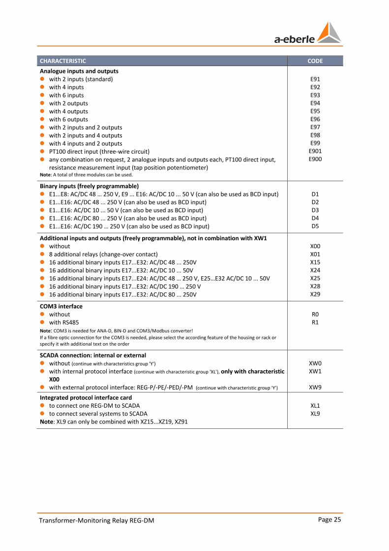
CHARACTERISTIC CODE
Analogue inputs and outputs 0 with 2 inputs (standard) 0 with 4 inputs 0 with 6 inputs 0 with 2 outputs 0 with 4 outputs 0 with 6 outputs 0 with 2 inputs and 2 outputs 0 with 2 inputs and 4 outputs 0 with 4 inputs and 2 outputs 0 PT100 direct input (three-wire circuit) 0 any combination on request, 2 analogue inputs and outputs each, PT100 direct input,
resistance measurement input (tap position potentiometer)
Note: A total of three modules can be used.
E91 E92 E93 E94 E95 E96 E97 E98 E99
E901 E900
Binary inputs (freely programmable) 0 E1...E8: AC/DC 48 … 250 V, E9 ... E16: AC/DC 10 ... 50 V (can also be used as BCD input) 0 E1...E16: AC/DC 48 ... 250 V (can also be used as BCD input) 0 E1...E16: AC/DC 10 ... 50 V (can also be used as BCD input) 0 E1...E16: AC/DC 80 ... 250 V (can also be used as BCD input) 0 E1...E16: AC/DC 190 … 250 V (can also be used as BCD input)
D1 D2 D3 D4 D5
Additional inputs and outputs (freely programmable), not in combination with XW1 0 without 0 8 additional relays (change-over contact) 0 16 additional binary inputs E17...E32: AC/DC 48 ... 250V 0 16 additional binary inputs E17...E32: AC/DC 10 ... 50V 0 16 additional binary inputs E17...E24: AC/DC 48 … 250 V, E25…E32 AC/DC 10 ... 50V 0 16 additional binary inputs E17...E32: AC/DC 190 … 250 V 0 16 additional binary inputs E17...E32: AC/DC 80 ... 250V
X00 X01 X15 X24 X25 X28 X29
COM3 interface 0 without 0 with RS485 Note: COM3 is needed for ANA-D, BIN-D and COM3/Modbus converter!
If a fibre optic connection for the COM3 is needed, please select the according feature of the housing or rack or specify it with additional text on the order
R0 R1
SCADA connection: internal or external 0 without (continue with characteristics group 'Y') 0 with internal protocol interface (continue with characteristic group 'XL'), only with characteristic
X00 0 with external protocol interface: REG-P/-PE/-PED/-PM (continue with characteristic group 'Y')
XW0 XW1
XW9
Integrated protocol interface card 0 to connect one REG-DM to SCADA 0 to connect several systems to SCADA Note: XL9 can only be combined with XZ15...XZ19, XZ91
XL1 XL9

Transformer-Monitoring Relay REG-DM Page 26
Page 26
We take care of it
CHARACTERISTIC CODE
Connection type 0 Copper conductors – RS232 – RS485 2-wire operation only
Note: XV13 ... XV19 can only be selected with B02…B95. In all other cases, select a suitable fibre optic cable module!
0 Fibre optic cable with FSMA connection technology – Fibreglass (Wave length 800...900 nm, range 2000 m) – All-plastic (Wave length 620...680 nm, range 50 m)
0 Fibre optic cable with ST connection technology – Fibreglass (Wave length 800...900 nm, range 2000 m) – All-plastic (Wave length 620...680 nm, range 50 m)
XV10 XV11
XV13 XV15
XV17 XV19
Protocol 0 IEC60870-5-103 for ABB 0 IEC60870-5-103 for Areva 0 IEC60870-5-103 for SAT 0 IEC60870-5-103 for Siemens (LSA/SAS) 0 IEC60870-5-103 for Sprecher Automation 0 IEC60870-5-103 for others 0 IEC60870-5-101 for ABB 0 IEC60870-5-101 for IDS 0 IEC60870-5-101 for SAT 0 IEC60870-5-101 for Siemens (LSA/SAS) 0 IEC60870-5-101 for others 0 DNP 3.00 0 LONMark (ask for availability) 0 SPABUS 0 MODBUS RTU
XZ10 XZ11 XZ12 XZ13 XZ14 XZ90 XZ15 XZ17 XZ18 XZ19 XZ91 XZ20 XZ21 XZ22 XZ23
Local/Remote control via keyboard (local/remote key) 0 without 0 with
Y0 Y1
Status contact 0 closes in case of malfunction (NC contact) 0 opens in case of malfunction (NO contact)
U0 U1
Operating instructions 0 German 0 English 0 Other (on request)
G1 G2
G10
Display language 0 German 0 English 0 Spanish 0 Others (on request)
A1 A2 A4
A11

Page 27
Page 27
Transformer-Monitoring Relay REG-DM
REGSys™ Accessories ID-No.
Rack design:
Female multipoint connector 1 (Electrical connector block, model F, wire wrap, 32 pins) 582.0197
Female multipoint connector 1 (Electrical connector block, model F, wire wrap, 48 pins) 582.0196.01
Female multipoint connector 1 (Electrical connector block, model F, 2.8 FASTON, 32 pins) 582.0213.01
Female multipoint connector 1 (Electrical connector block, model F, 2.8 FASTON, 48 pins) 582.0213
Female multipoint connector 2 (Current input with advanced contacts, 2 pole) 582.0258.10
Female multipoint connector 4 (Current input with advanced contacts, 6 pole) 582.0258.20
Female multipoint connector 3 (Mixed connector model F24 + H7, wire wrap) 582.0215
Female multipoint connector 3 (Mixed connector model F16 + H7, 6.3/2.8 FASTON) 582.0214
Female multipoint connector 3 (Mixed connector model F24 + H7, 6.3/2.8 FASTON) 582.0217
Panel plate 28 HP 566.0028
Panel plate 18 HP 566.0018
Panel plate 14 HP 566.0014
Panel plate 10 HP 566.0010
Panel plate 8 HP 566.0008
Panel plate 7 HP 566.0007
Panel plate 6 HP 566.0006
Panel plate 5 HP 566.0005
Panel plate 4 HP 566.0004
Panel plate 2 HP 566.0002
Fuses, batteries:
1 pack microfuses T1 L 250 V, 1 A, for auxiliary voltage range H0 and H1 582.1002
1 pack microfuses T2 L 250 V, 2 A, for auxiliary voltage range H2 582.1019
1 lithium battery (pluggable) 570.0003.00
1 lithium battery (solderable) on request
1 button cell CR1632 on request
Connection technique:
PC connection cable (null-modem cable) 582.020B.00
USB connection cable (USB A <-> USB B Mini) 582.020U.00
Modem connection cable 582.2040
RS232 10 m extension cable 582.2040.10
USB/RS232 adapter with integrated null-modem cable (FTDI), 1,5m 111.9046.01
Interface E-LAN-FO: RS485/FO (E-LAN → FO or FO→ E-LAN) FO-connector ST Note: 2 units required per line! connection, 2 units needed for each line
111.9030.10
Interface E-LAN-FO: RS485/FO (E-LAN → FO or FO→ E-LAN) FO-connector LC Note: 2 units required per line! connection, 2 units needed for each line
111.9030.11
E-LAN Booster, Uh: DC 20…75V, DIN-rail, 22.5mm; power supply 111.9030.36 if necessary pter H1 111.9030.36
111.9027.02
E-LAN Router, one output with Booster; Uh: DC20…75V DIN-rail type, 22,5mm; power supply 111.9030.36 if necessary
111.9027.03
Time synchronisation:
Radio controlled clock (DFC 77) 111.9024.01
GPS radio clock NIS time, RS485, Uh: AC 85 V ... 110V ... 264 V / DC 88 V ... 220V ... 280V 111.9024.45
GPS radio clock NIS time, RS485, Uh: DC 18 V ... 60V ... 72V 111.9024.46
GPS radio clock NIS time, RS232, Uh: AC 85 V ... 110V ... 264 V / DC 88 V ... 220V ... 280V 111.9024.47
GPS radio clock NIS time, RS232, Uh: DC 18 V ... 60V ... 72V 111.9024.48

Transformer-Monitoring Relay REG-DM Page 28
Page 28
We take care of it
REGSys™ Accessories ID-No.
Modems:
Develo MicroLink 56Ki analogue modem, tabletop device incl. 230 V AC mains adapter 111.9030.02
Develo MicroLink 56Ki analogue modem, DIN-rail device incl. 230 V AC mains adapter 111.9030.03
Industrial analogue modem that can be used as dial-up modem or dedicated line; (Uh: AC 20..260 V/DC 14 V..280 V) with DIN-rail adapter; can be used with the PC and the device!
111.9030.17
Insys industrial analogue modem that can be as a dedicated line; supply voltage DC: 10…60 V, can be used with the PC and the device!
111.9030.20
ISDN modem for DIN-rail mount; Uh: DC 10 … 60 V 111.9030.27
ISDN modem as tabletop device; incl. 230 V AC power supply adapter 111.9030.37
GPRS modem (Insys) for DIN-rail mount; incl. magnet foot antenna and parameterisation software; Uh: DC 10 ..60 V
111.9030.29
Power supply:
Phoenix power supply adapter for DIN-rail mounting: In: AC 120 V...230 V, DC 90 … 250 V, 111.9005.02
Power supply for DIN-rail mounting: In: AC 80 V...250 V; Out: DC 24 V 111.9030.31
Power supply for DIN-rail mounting: In: DC 18 V...60 V...72 V; Out: DC 24 V 111.9030.32
Power supply for E-LAN router or booster: In: AC 100 to 240 V, Out: 24 V/1.3 A 111.9030.36
UPS HighCAP2403-1AC, In: 230 V AC Out: 24 V DC, max. 3 A, 1000 Joule (1 kWs), DIN-Rail 111.9030.38
Additional input and output module:
Analogue input module (2 inputs) 320.0004.00
Analogue output module (2 outputs) 320.0003
Input module for tap-potentiometer total resistance 180 ...2 kΩ, min. 5 Ω/tap 320.0002.01
Input module for tap-potentiometer total resistance 2 ...20 kΩ, min. 50 Ω/tap 320.0002.03
Input module for PT100 in conformity with DIN 43760 in three-wire connection 320.0005.01
Operating manual:
Additional operating manual for REG-DM GX
General add-ons ID-No.
Profibus DP module incl. RS485 interface and connection cable 0 Model: – Mountable on DIN-rail (120 x 75 x 27) mm with ext. 24 V power supply adapter
– Plug-in module: 12 HP/3 U incl. AC 85…264 V mains adapter, DC 88…280 V
– Plug-in module: 12 HP/3 U incl. DC 18…72 V mains adapter
Profi-DP
B0 B1 B2
TCP/IP adapter TCP/IP adapter (10 Mbit) 0 Model – Mountable on DIN-rail with 230 V AC power supply adapter for UH
– As plug-in module 8 HP, 3 U with mains adapter: AC 85 V ... 110V ... 264 V / DC 88 V ... 220 V ... 280 V
– As plug-in module 8 HP, 3 U with mains adapter: DC 18 V ... 60V ... 72V
TCP/IP adapter (100 Mbit)
REG-COM
A01 A02
A03 A90
COM3 converter COM3 to Modbus converter to connect external devices with Modbus interface to the transformer monitoring module. For example, to analyse the gas-in-oil ratio online, directly measure the winding temperature, etc.
0 Auxiliary voltage
– AC 85…264 V, DC 88 … 280 V, DC 18 … 72 V
– DC 18 … 72 V
COM3-MOD
H1 H2

Page 29
Page 29
Transformer-Monitoring Relay REG-DM
General add-ons ID-No.
IRIG-DCF77 – converter 0 Auxiliary voltage
– AC 85 … 264 V, DC 88…280 V
– DC 18 … 72 V
0 Model
– Plug-in module 10 HP, 3 U
– Wall-mounted housing 20 HP
0 Operating instructions
– German
– English
IRIG-DCF
H1 H2
B1 B2
G1 G2
Power supply adapter for REG-PE 3 U/6 HP, 15 Watt Must always be used when the 19” rack doesn't have a REGSys device or Usync and for module 2 when the 19” rack is not configured with an H11 device and a Usync is not integrated.
0 Auxiliary voltage – AC 85…264 V, DC 88 … 280 V
– DC 18 … 72 V
REG-NTZ
H1 H2

Transformer-Monitoring Relay REG-DM Page 30
Page 30
We take care of it
Notes

Page 31
Page 31
Transformer-Monitoring Relay REG-DM
Notes

A. Eberle GmbH & Co. KG
Frankenstraße 160 D-90461 Nuremberg
Tel.: +49-(0)911-62 81 08-0 Fax: +49-(0)911-62 81 08-96 E-mail: [email protected]
http://www.a-eberle.de
Provided by:
_______________________________
Copyright 2015 by A. Eberle GmbH & Co. KG
Subject to change without prior notice.


![[XLS] · Web viewSGR-12 RECLOSING RELAY TT-8 RELAY PERCENTAGE DIFFERENTIAL TRANSFORMER CVE SYNCRO VERIFIER RELAY HU-4 TRANSFORMER DIFFERENTIAL RELAY HCB RELAY TD-5 TIME DELAY RELAY](https://img.pdfslide.net/doc/110x75/5aebb2387f8b9a36698eaca3/xls-viewsgr-12-reclosing-relay-tt-8-relay-percentage-differential-transformer.jpg)