Embed Size (px)
Citation preview
T060D201-00 Version February 2006
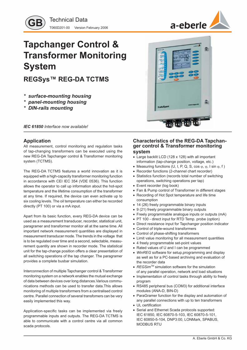
REGSys™ REG-DA TCTMS
Tapchanger Control &Transformer Monitoring System
* surface-mounting housing* panel-mounting housing* DIN-rails mounting
ApplicationAll measurement, control monitoring and regulation tasks of tap-changing transformers can be executed using the new REG-DA Tapchanger control & Transformer monitoring system (TCTMS).
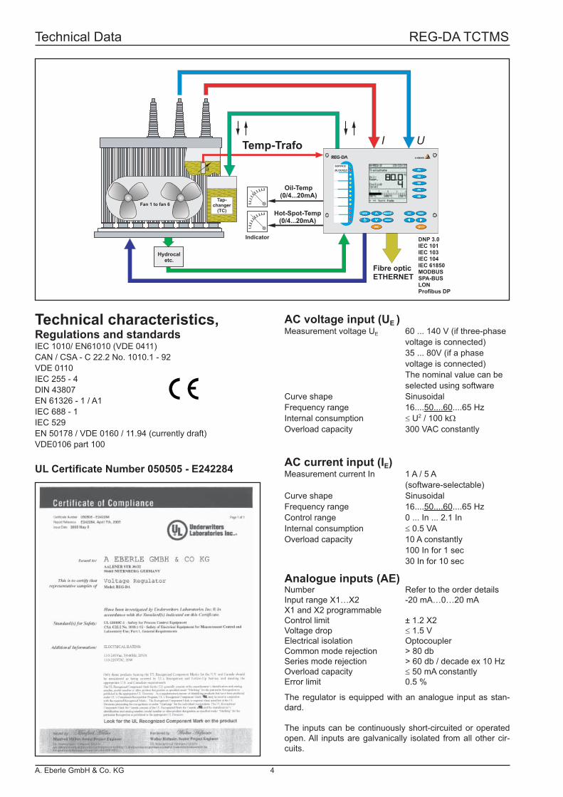
The REG-DA TCTMS features a world innovation as it is equipped with a high-capacity transformer monitoring function in accordance with CEI IEC 354 (VDE 0536). This function allows the operator to call up information about the hot-spot temperature and the lifetime consumption of the transformer at any time. If required, the device can even activate up to six cooling levels. The oil temperature can either be recorded directly (PT 100) or via a mA input.
Apart from its basic function, every REG-DA device can be used as a measurement transducer, recorder, statistical unit, paragramer and transformer monitor all at the same time. All important network measurement quantities are displayed in measurement transducer mode. The trends in the voltage that is to be regulated over time and a second, selectable, measu-rement quantity are shown in recorder mode. The statistical unit for the tap-change position offers a clear presentation of all switching operations of the tap changer. The paragramer provides a complete busbar simulation.
Interconnection of multiple Tapchanger control & Transformer monitoring system on a network enables the mutual exchange of data between devices over long distances.Various commu-nications methods can be used to transfer data.This allows monitoring of multiple transformers from a centralised control centre. Parallel connection of several transfomers can be very easily implemented this way.
Application-specifi c tasks can be implemented via freely programmable inputs and outputs. The REG-DA TCTMS is able to communicate with a control centre via all common scada protocols.
Characteristics of the REG-DA Tapchan-ger control & Transformer monitoring system• Large backlit LCD (128 x 128) with all important information (tap-change position, voltage, etc.)• Measuring functions (U, I, P, Q, S, cos ϕ, ϕ, I sin ϕ, f )• Recorder functions (2-channel chart recorder)• Statistics function (records total number of switching operations, switching operations per tap)• Event recorder (log book)• Fan & Pump control of Transformer in different stages• Recording of Hot Spot temperature and life time consumption• 14 (26) freely programmable binary inputs• 9 (21) freely programmable binary outputs• Freely programmable analogue inputs or outputs (mA)• PT 100 - direct input for RTD Temp. probe (option)• Direct resistance input for Tapchanger position indicator• Control of triple-wound transformers• Control of phase-shifting transformers• Limit value monitoring for all measurement quantities• 4 freely programmable set-point values• Rated values of U and I can be programmed• WinREG software for setup,programming and display as well as for a PC-based archiving and evaluation of the recorder data• REGSimTM simulation software for the simulation of any parallel operation, network and load situations• Implementation of control tasks through ability to freely program• RS485 peripheral bus (COM3) for additional interface modules (ANA-D, BIN-D)• ParaGramer function for the display and automation of any parallel connections with up to ten transformers• UL certifi cation• Serial and Ethernet Scada protocols supported: IEC 61850, IEC 60870-5-103, IEC 60870-5-101, IEC 60850-5-104, DNP3:00, LONMark, SPABUS, MODBUS RTU
IEC 61850 Interface now available!
GB
A. Eberle GmbH & Co. KG
Technical Dataa-eberle
RS232
RS232
RS485
Status
E-LANRS485
1
2
3
4
5
6 7
8
9
10
11
12
13
COM 1
COM 2
COM 3
µP
LCD
LED
RAM
ROM
CLOCK
SERVICEBLOCKED
F3F3
F2F2
F1F1
F4F4
F5F5
AUTOAUTO REMOTEREMOTE
LOCALLOCAL
ACKACK
MENUMENUESCESC
REG-DAREG-DA a-eberle
SERVICEBLOCKED
F3F3
F2F2
F1F1
F4F4
F5F5
AUTOAUTO REMOTEREMOTE
LOCALLOCAL
ACKACK
MENUMENUESCESC
REG-DAREG-DA a-eberle
Case differentia-tion
REG-DA program
Boundary conditions
Parallel operation on one (several) busbar (s)
∆I sin ϕ Identical transformers, equal or different tap change
∆I sin ϕ (S) Transformers with diffe-rent powers, different or equal tap changes
Master-slave
Identical transformers, equal tap change
Freely switched in parallel
∆ cos ϕ Any transformers, any tap changes
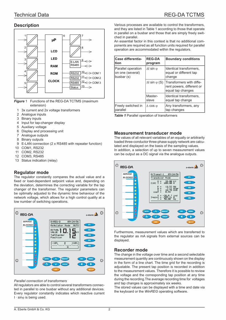
Description
Figure 1 Functions of the REG-DA TCTMS (maximum extension) 1 3x current and 2x voltage transformers 2 Analogue inputs 3 Binary inputs 4 Input for tap-changer display 5 Auxiliary voltage 6 Display and processing unit 7 Analogue outputs 8 Binary outputs 9 E-LAN connection (2 x RS485 with repeater function) 10 COM1, RS232 11 COM2, RS232 12 COM3, RS485 13 Status indication (relay)
Regulator modeThe regulator constantly compares the actual value and a fi xed or load-dependent setpoint value and, depending on the deviation, determines the correcting variable for the tap changer of the transformer. The regulator parameters can be optimally adjusted to the dynamic time behaviour of the network voltage, which allows for a high control quality at a low number of switching operations.
Parallel connection of transformersAll regulators are able to control several transformers connec-ted in parallel to one busbar without any additional devices. Every regulator constantly indicates which reactive current I · sinϕ is being used.
Various processes are available to control the transformers, and they are listed in Table 1 according to those that operate in parallel on a busbar and those that are simply freely swit-ched in parallel.An essential factor in this context is that no additional com-ponents are required as all function units required for parallel operation are accommodated within the regulators.
Table 1 Parallel operation of transformers
Measurement transducer modeThe values of all relevant variables of an equally or arbitrarily loaded three-conductor three-phase supply network are calcu-lated and displayed on the basis of the sampling values.In addition, a selection of up to seven measurement values can be output as a DC signal via the analogue outputs.
Recorder modeThe change in the voltage over time and a second selectable measurement quantity are continuously shown on the display in the form of a line chart. The time grid for the recording is adjustable. The present tap position is recorded in addition to the measurement values. Therefore it is possible to review the voltage and the corresponding tap position at any time during the recording.The average recording time for voltages and tap changes is approximately six weeks.The stored values can be displayed with a time and date via the keyboard or the WinREG operating software.
Furthermore, measurement values which are transferred to the regulator as mA signals from external sources can be displayed.
Technical Data REG-DA TCTMS
A. Eberle GmbH & Co. KG 2
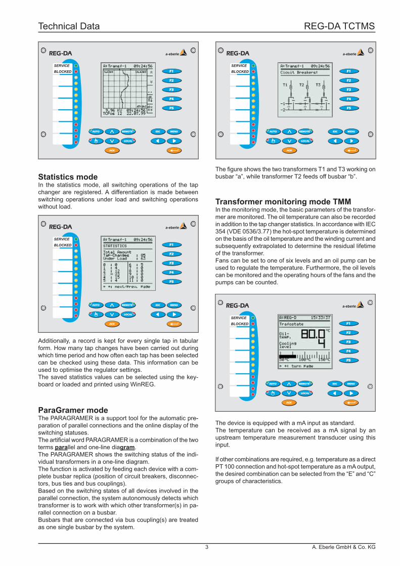
Statistics modeIn the statistics mode, all switching operations of the tap changer are registered. A differentiation is made between switching operations under load and switching operations without load.
ParaGramer modeThe PARAGRAMER is a support tool for the automatic pre-paration of parallel connections and the online display of the switching statuses.The artifi cial word PARAGRAMER is a combination of the two terms parallel and one-line diagram.The PARAGRAMER shows the switching status of the indi-vidual transformers in a one-line diagram.The function is activated by feeding each device with a com-plete busbar replica (position of circuit breakers, disconnec-tors, bus ties and bus couplings).Based on the switching states of all devices involved in the parallel connection, the system autonomously detects which transformer is to work with which other transformer(s) in pa-rallel connection on a busbar.Busbars that are connected via bus coupling(s) are treated as one single busbar by the system.
Transformer monitoring mode TMMIn the monitoring mode, the basic parameters of the transfor-mer are monitored. The oil temperature can also be recorded in addition to the tap changer statistics. In accordance with IEC 354 (VDE 0536/3.77) the hot-spot temperature is determined on the basis of the oil temperature and the winding current and subsequently extrapolated to determine the residual lifetime of the transformer.Fans can be set to one of six levels and an oil pump can be used to regulate the temperature. Furthermore, the oil levels can be monitored and the operating hours of the fans and the pumps can be counted.
The device is equipped with a mA input as standard.The temperature can be received as a mA signal by an upstream temperature measurement transducer using this input.
If other combinations are required, e.g. temperature as a direct PT 100 connection and hot-spot temperature as a mA output, the desired combination can be selected from the “E” and “C” groups of characteristics.
Additionally, a record is kept for every single tap in tabular form. How many tap changes have been carried out during which time period and how often each tap has been selected can be checked using these data. This information can be used to optimise the regulator settings.The saved statistics values can be selected using the key-board or loaded and printed using WinREG.
The fi gure shows the two transformers T1 and T3 working on busbar “a”, while transformer T2 feeds off busbar “b”.
SERVICEBLOCKED
F3F3
F2F2
F1F1
F4F4
F5F5
AUTOAUTO REMOTEREMOTE
LOCALLOCAL
ACKACK
MENUMENUESCESC
REG-DAREG-DA a-eberle
SERVICEBLOCKED
F3F3
F2F2
F1F1
F4F4
F5F5
AUTOAUTO REMOTEREMOTE
LOCALLOCAL
ACKACK
MENUMENUESCESC
REG-DAREG-DA a-eberle
SERVICEBLOCKED
F3F3
F2F2
F1F1
F4F4
F5F5
AUTOAUTO REMOTEREMOTE
LOCALLOCAL
ACKACK
MENUMENUESCESC
REG-DAREG-DA a-eberle
SERVICEBLOCKED
F3F3
F2F2
F1F1
F4F4
F5F5
AUTOAUTO REMOTEREMOTE
LOCALLOCAL
ACKACK
MENUMENUESCESC
REG-DAREG-DA a-eberle
Technical Data REG-DA TCTMS
3 A. Eberle GmbH & Co. KG
ϑ
I U
Hot-Spot-Temp(0/4...20mA)
Oil-Temp(0/4...20mA)
Indicator
Tap-changer
(TC)
Temp-Trafo
Fibre opticETHERNET
DNP 3.0IEC 101IEC 103IEC 104IEC 61850MODBUSSPA-BUSLONProfibus DP
Fan 1 to fan 6
Hydrocaletc.
SERVICEBLOCKED
F3F3
F2F2
F1F1
F4F4
F5F5
AUTOAUTO REMOTEREMOTE
LOCALLOCAL
ACKACK
MENUMENUESCESC
REG-DAREG-DA a-eberle
Technical characteristics,Regulations and standardsIEC 1010/ EN61010 (VDE 0411)CAN / CSA - C 22.2 No. 1010.1 - 92VDE 0110IEC 255 - 4DIN 43807EN 61326 - 1 / A1IEC 688 - 1IEC 529EN 50178 / VDE 0160 / 11.94 (currently draft)VDE0106 part 100
Analogue inputs (AE)Number Refer to the order detailsInput range X1…X2 -20 mA…0…20 mAX1 and X2 programmableControl limit ± 1.2 X2Voltage drop ≤ 1.5 VElectrical isolation OptocouplerCommon mode rejection > 80 dbSeries mode rejection > 60 db / decade ex 10 HzOverload capacity ≤ 50 mA constantlyError limit 0.5 %
AC voltage input (UE )Measurement voltage UE 60 ... 140 V (if three-phase voltage is connected) 35 ... 80V (if a phase voltage is connected) The nominal value can be selected using softwareCurve shape SinusoidalFrequency range 16....50....60....65 HzInternal consumption ≤ U2 / 100 kΩOverload capacity 300 VAC constantly
AC current input (IE)Measurement current In 1 A / 5 A (software-selectable)Curve shape SinusoidalFrequency range 16....50....60....65 HzControl range 0 ... In ... 2.1 InInternal consumption ≤ 0.5 VAOverload capacity 10 A constantly 100 In for 1 sec 30 In for 10 sec
UL Certifi cate Number 050505 - E242284
The regulator is equipped with an analogue input as stan-dard.
The inputs can be continuously short-circuited or operated open. All inputs are galvanically isolated from all other cir-cuits.
Technical Data REG-DA TCTMS
A. Eberle GmbH & Co. KG 4
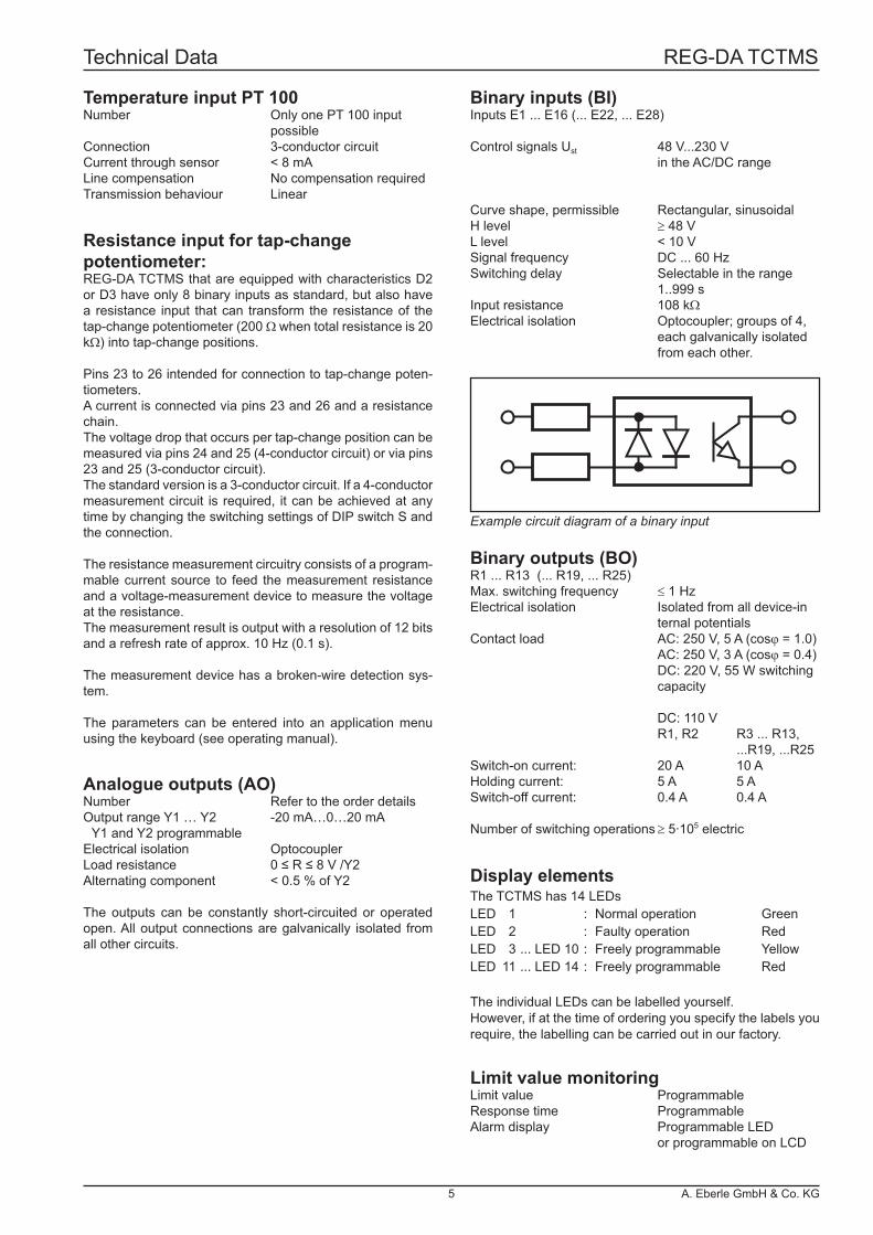
Binary outputs (BO)R1 ... R13 (... R19, ... R25)Max. switching frequency ≤ 1 HzElectrical isolation Isolated from all device-in ternal potentialsContact load AC: 250 V, 5 A (cosϕ = 1.0) AC: 250 V, 3 A (cosϕ = 0.4) DC: 220 V, 55 W switching capacity
DC: 110 V R1, R2 R3 ... R13, ...R19, ...R25Switch-on current: 20 A 10 AHolding current: 5 A 5 ASwitch-off current: 0.4 A 0.4 A
Number of switching operations ≥ 5·105 electric
Binary inputs (BI)Inputs E1 ... E16 (... E22, ... E28)
Control signals Ust 48 V...230 V in the AC/DC range
Curve shape, permissible Rectangular, sinusoidalH level ≥ 48 VL level < 10 VSignal frequency DC ... 60 HzSwitching delay Selectable in the range 1..999 sInput resistance 108 kΩElectrical isolation Optocoupler; groups of 4, each galvanically isolated from each other.
Resistance input for tap-changepotentiometer:REG-DA TCTMS that are equipped with characteristics D2 or D3 have only 8 binary inputs as standard, but also have a resistance input that can transform the resistance of the tap-change potentiometer (200 Ω when total resistance is 20 kΩ) into tap-change positions.
Pins 23 to 26 intended for connection to tap-change poten-tiometers.A current is connected via pins 23 and 26 and a resistance chain.The voltage drop that occurs per tap-change position can be measured via pins 24 and 25 (4-conductor circuit) or via pins 23 and 25 (3-conductor circuit).The standard version is a 3-conductor circuit. If a 4-conductor measurement circuit is required, it can be achieved at any time by changing the switching settings of DIP switch S and the connection.
The resistance measurement circuitry consists of a program-mable current source to feed the measurement resistance and a voltage-measurement device to measure the voltage at the resistance.The measurement result is output with a resolution of 12 bits and a refresh rate of approx. 10 Hz (0.1 s).
The measurement device has a broken-wire detection sys-tem. The parameters can be entered into an application menu using the keyboard (see operating manual).
Analogue outputs (AO)Number Refer to the order detailsOutput range Y1 … Y2 -20 mA…0…20 mA Y1 and Y2 programmableElectrical isolation OptocouplerLoad resistance 0 ≤ R ≤ 8 V /Y2Alternating component < 0.5 % of Y2
The outputs can be constantly short-circuited or operated open. All output connections are galvanically isolated from all other circuits.
Temperature input PT 100Number Only one PT 100 input possibleConnection 3-conductor circuitCurrent through sensor < 8 mA Line compensation No compensation requiredTransmission behaviour Linear
Example circuit diagram of a binary input
Limit value monitoringLimit value ProgrammableResponse time ProgrammableAlarm display Programmable LED or programmable on LCD
Display elementsThe TCTMS has 14 LEDsLED 1 : Normal operation GreenLED 2 : Faulty operation RedLED 3 ... LED 10 : Freely programmable YellowLED 11 ... LED 14 : Freely programmable Red
The individual LEDs can be labelled yourself.However, if at the time of ordering you specify the labels you require, the labelling can be carried out in our factory.
Technical Data REG-DA TCTMS
5 A. Eberle GmbH & Co. KG

Test voltages Hous.COM 1 Uh
COM 2COM 3 BO BI AI AO UE IE
Housing / COM 1 Hous. - 2.2 0.35 1.35 1.35 0.35 0.35 1.35 1.35Auxiliary voltage Uh 2.2 - 3.7 2.9 2.9 3.7 3.7 2.6 2.6COM 2/3 / IEC / DNP.. COMs 0.35 3.7 - 2.3 2.3 0.5 0.5 2.8 2.8Binary outputs BO 2.0 2.9 2.3 - 2.0 2.3 2.3 2.6 2.6Binary inputs (250 V) BI 2.0 2.9 2.3 2.0 - 2.3 2.3 2.6 2.6Analogue inputs AI 0.35 3.7 0.5 2.3 2.3 - 0.5 2.8 2.8Analogue outputs AO 0.35 3.7 0.5 2.3 2.3 0.5 - 2.8 2.8Input voltage UE 1.35 2.6 2.8 2.6 2.6 2.8 2.8 - 2.2Input current IE 2.0 2.6 2.8 2.6 2.6 2.8 2.8 2.2 -
III IIInput circuits of the current and voltage transformers Auxiliary voltage
Control circuits, analogue inputs, analogue outputsCOMs, E-LAN
50 V 150 V 230 VE-LAN,COM1...COM3,analogue inputs,analogue outputs,inputs 10...50 V
Voltage inputs,current inputs
Auxiliary voltage,binary inputs(E1...E16),relay outputs (R1...R13), status
Measurement quantities (optionally as mA value)Voltages TRMS U12, U23, U31 (≤ 0.25 %)Current TRMS I1, I2 , I3 (≤ 0.25 %)
Active power P (≤ 0.5 %)Reactive power Q (≤ 0.5 %)Apparent power S (≤ 0.5 %)Power factor cos ϕ (≤ 0.5 %)Phase angle ϕ (≤ 0.5 %)Reactive current I · sin ϕ (≤ 1 %)Frequency f (≤ 0.05 %)
Reference conditionsReference temperature 23°C ± 1 KInput quantities UE = 60 ... 140 V IE = 0 ... 1A / 0 ... 5 AAuxiliary voltage H = Hn ± 1 %Frequency 50 Hz...60 HzCurve shape Sinusoidal, form factor 1.1107Load (only for characteristics E91..E99) Rn = 5 V / Y2 ± 1 %Other IEC 688 - Part 1
Transmission behaviour of the analogue outputsError limit 0.05% / 0.25% / 0.5% / 1% related to Y2 (see “Meas- rement quantities”)Measurement cycle time ≤ 10 ms
Electrical safetyProtection class IDegree of pollution 2Overvoltage category II, III
Operating voltages
Notes: All test voltages are AC voltages in kV which may be applied for 1 minute. E-LAN, COM2, COM3 are tested against each other with 0.5 kV.
EMC requirements EN 61326-1 Device class A Continuous, non-monitored operation, in industrial applications and EN 61000-6-2 and 61000-6-4
Emitted interference Conducted EN 61326 Table 3 andand radiated EN 61000-6-4emission
Harmonic currents EN 61000-3-2
Voltage fl uctuations EN 61000-3-3and fl icker
Immunity to interference EN 61326 Table A1 and EN 61000-6-2
ESD IEC 61000-4-2 8 kV / 15 kV contact / air
Electromagnetic fi elds IEC 61000-4-3 80 – 2000 MHz: 10 V/m
Fast transients IEC 61000-4-4 4kV / 2kV
Surge voltages IEC 61000-4-5 4kV / 2kV
Conducted IEC 61000-4-6HF signals 150 kHz – 80 MHz: 10 V
Magnetic fi elds with heavy IEC 61000-4-8electrical frequencies 100 A/m (50 Hz), continuous 1000 A/m (50 Hz), 1 s
Voltage dips IEC 61000-4-11 30 % / 20 ms, 60 % / 1 s
Interruptions to the voltage IEC 61000-4-11 100 % / 5s
Damped oscillations IEC 61000-4-12, Class 3, 2.5 kV
Technical Data REG-DA TCTMS
A. Eberle GmbH & Co. KG 6
Product Type Fibre Pmin[dBm]
2)
Pmax[dBm]
2)
Glass STGlass SMA
HFBR 2412 THFBR 24020 ... 5 MBdλ = 820 nm
100/140 µmNA=0.3
-24.0 -10.0
POF_ST HFBR 2515 B0 ... 10 MBdλ = 650 nm
1 mm POF -20.0 0.0
200µm HCS -22.0 -2.0
POF_SMA HFBR 2505 C0 ... 10 MBdλ = 650 nm
1 mm POF -21.6 -2.0
200µm HCS -23.0 -3.4
Product Type Fibre Pmin[dBm]
1)
Pmax[dBm]
1)
Glass STGlass SMA
HFBR 1414 THFBR 1404
λ = 820 nm
50/125 µmNA=0.2
-19.8 -12.8
62.5/125 µmNA=0.275
-16.0 -9.0
100/140 µmNA=0.3
-10.5 -3.5
200µm HCSNA=0.37
-6.2 +1.8
POF_ST HFBR 1515Bλ = 650 nm
1 mm POF -7.5 -3.5
200µm HCS -18.0 -8.5
POF_SMA HFBR 1505Cλ = 650 nm
1 mm POF -6.2 0.0
200µm HCS -16.9 -8.5
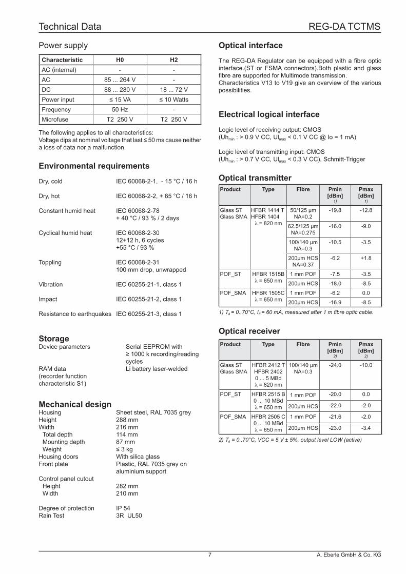
Characteristic H0 H2AC (internal) - -AC 85 ... 264 V -DC 88 ... 280 V 18 ... 72 VPower input ≤ 15 VA ≤ 10 WattsFrequency 50 Hz -Microfuse T2 250 V T2 250 V
Mechanical designHousing Sheet steel, RAL 7035 greyHeight 288 mmWidth 216 mm Total depth 114 mm Mounting depth 87 mm Weight ≤ 3 kgHousing doors With silica glassFront plate Plastic, RAL 7035 grey on aluminium supportControl panel cutout Height 282 mm Width 210 mm
Degree of protection IP 54Rain Test 3R UL50
Power supply
The following applies to all characteristics:Voltage dips at nominal voltage that last ≤ 50 ms cause neither a loss of data nor a malfunction.
StorageDevice parameters Serial EEPROM with ≥ 1000 k recording/reading cyclesRAM data Li battery laser-welded(recorder functioncharacteristic S1)
Environmental requirements
Dry, cold IEC 60068-2-1, - 15 °C / 16 h
Dry, hot IEC 60068-2-2, + 65 °C / 16 h
Constant humid heat IEC 60068-2-78 + 40 °C / 93 % / 2 days
Cyclical humid heat IEC 60068-2-30 12+12 h, 6 cycles +55 °C / 93 %
Toppling IEC 60068-2-31 100 mm drop, unwrapped
Vibration IEC 60255-21-1, class 1
Impact IEC 60255-21-2, class 1
Resistance to earthquakes IEC 60255-21-3, class 1
Electrical logical interface Logic level of receiving output: CMOS(Uhmin : > 0.9 V CC, Ulmax < 0.1 V CC @ Io = 1 mA)
Logic level of transmitting input: CMOS(Uhmin : > 0.7 V CC, Ulmax < 0.3 V CC), Schmitt-Trigger
1) TA = 0..70°C, IF = 60 mA, measured after 1 m fi bre optic cable.
2) TA = 0..70°C, VCC = 5 V ± 5%, output level LOW (active)
Optical receiver
Optical transmitter
Optical interface
The REG-DA Regulator can be equipped with a fi bre optic interface.(ST or FSMA connectors).Both plastic and glass fi bre are supported for Multimode transmission.Characteristics V13 to V19 give an overview of the various possibilities.
Technical Data REG-DA TCTMS
7 A. Eberle GmbH & Co. KG
F3F3
F2F2
F1F1
F4F4
F5F5
AUTOAUTO REMOTEREMOTE
LOCALLOCAL
ACKACK
MENUMENUESCESC
REG-DA
SERVICEBLOCKED
REGSys™ www.regsys.de
1218 87 250
281
x 20
9
307
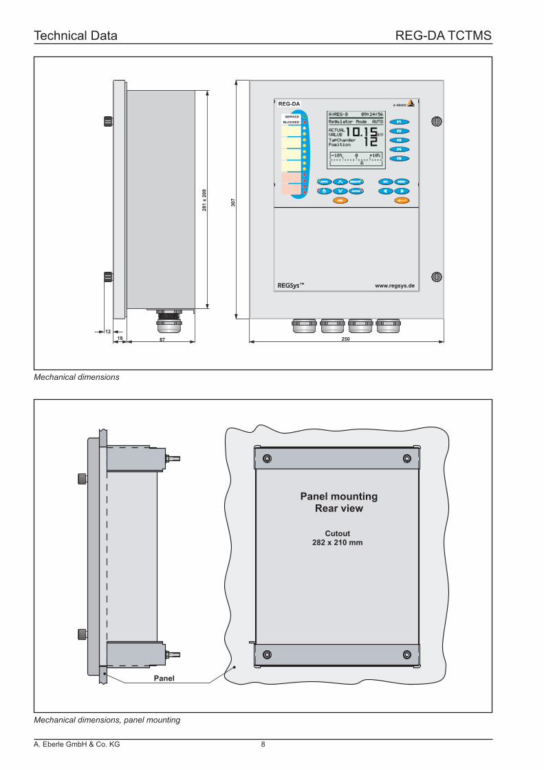
Panel mountingRear view
Cutout282 x 210 mm
Panel
Mechanical dimensions
Mechanical dimensions, panel mounting
Technical Data REG-DA TCTMS
A. Eberle GmbH & Co. KG 8
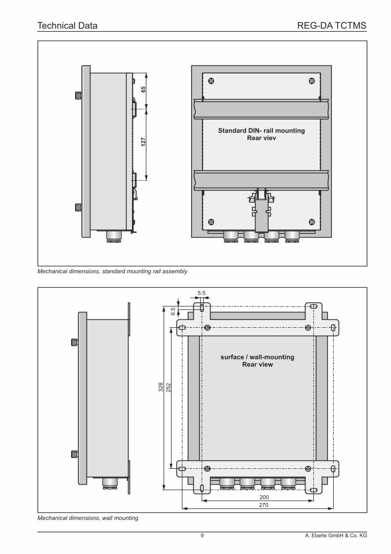
Standard DIN- rail Rear viev
mounting
127
65
surface / wall-mountingRear view
252
270200
328
6.5
5.5
Mechanical dimensions, standard mounting rail assembly
Mechanical dimensions, wall mounting
Technical Data REG-DA TCTMS
9 A. Eberle GmbH & Co. KG
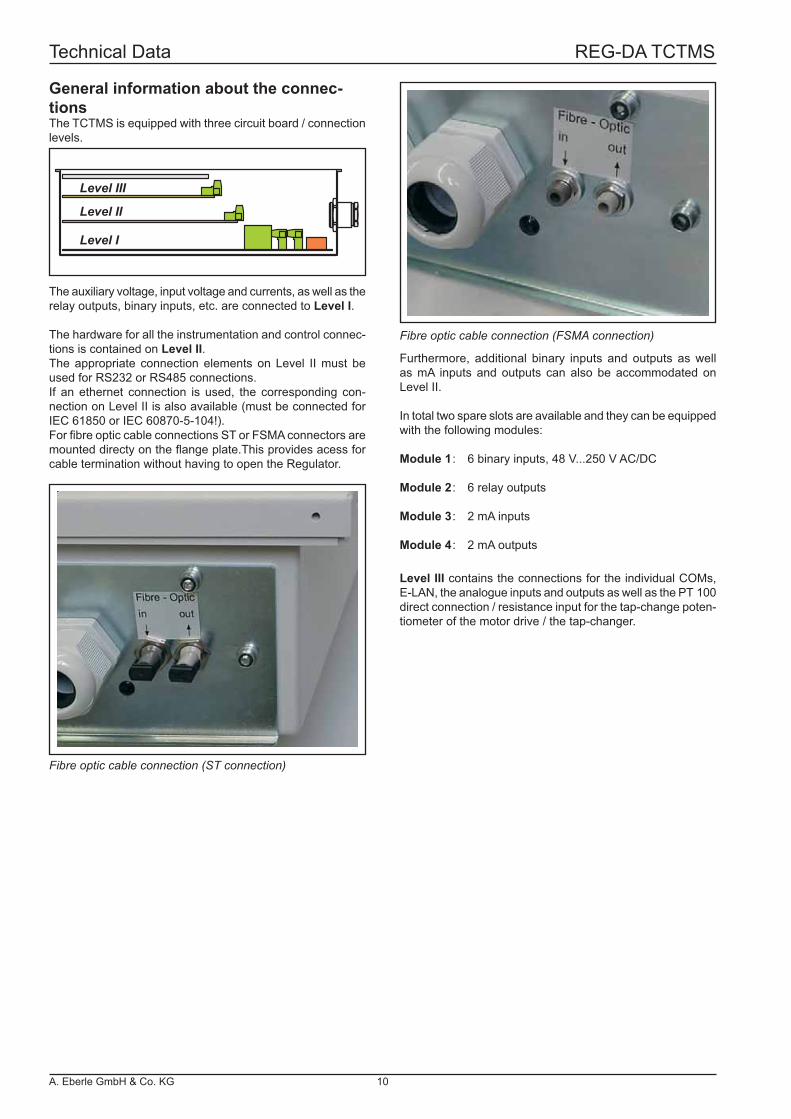
Level III
Level II
Level I
Furthermore, additional binary inputs and outputs as well as mA inputs and outputs can also be accommodated on Level II.
In total two spare slots are available and they can be equipped with the following modules:
Module 1 : 6 binary inputs, 48 V...250 V AC/DC
Module 2 : 6 relay outputs
Module 3 : 2 mA inputs
Module 4 : 2 mA outputs
General information about the connec-tionsThe TCTMS is equipped with three circuit board / connection levels.
The auxiliary voltage, input voltage and currents, as well as the relay outputs, binary inputs, etc. are connected to Level I.
The hardware for all the instrumentation and control connec-tions is contained on Level II.The appropriate connection elements on Level II must be used for RS232 or RS485 connections.If an ethernet connection is used, the corresponding con-nection on Level II is also available (must be connected for IEC 61850 or IEC 60870-5-104!).For fi bre optic cable connections ST or FSMA connectors are mounted directy on the fl ange plate.This provides acess for cable termination without having to open the Regulator.
Level III contains the connections for the individual COMs, E-LAN, the analogue inputs and outputs as well as the PT 100 direct connection / resistance input for the tap-change poten-tiometer of the motor drive / the tap-changer.
Fibre optic cable connection (ST connection)
Fibre optic cable connection (FSMA connection)
Technical Data REG-DA TCTMS
A. Eberle GmbH & Co. KG 10
65
66
68
No.
Leve
l I
Option M1* M2* Triple-wound transformer*
2 Input voltageU1
UL1 U15 Input voltage UL2
8 Input voltage-
UL3 U210 Input voltage -1 k
Current input I13 l4 k
Current input I26 l7 k
Current input I39 l21 L / (+)
UH = Auxiliary voltage22 L / (-)
Leve
l III
63 mA input + A164 mA input - A161 mA input or output + A262 mA input or output - A265 mA input or output + A366 mA input or output - A367 mA input or output + A468 mA input or output - A4
Leve
l I
11 Binary input 1 Activity lamp12 Binary input 2 Freely programmable13 Binary input 3 Freely programmable14 Binary input 4 Freely programmable15 Binary input 1...4 GND16 Binary input 5 AUTO17 Binary input 6 MANUAL18 Binary input 7 Freely programmable19 Binary input 8 Freely programmable20 Binary input 5...8 GND23 Binary input 9 BCD 124 Binary input 10 BCD 225 Binary input 11 BCD 426 Binary input 12 BCD 827 Binary input 9...12 GND28 Binary input 13 BCD 1029 Binary input 14 BCD 2030 Binary input 15 BCD sgn.31 Binary input 16 Freely programmable32 Binary input 13...16 GND33
Freely programmable R53435
Freely programmable R43637
Freely programmable R33839
Lower R240414243
Raise R1444546
Nr.
Leve
l I
47 > I R11
48 > U R10
49 < U R9
50 Local R8
51 Remote R7
52 TC error ** R6
53 GND R6...R11
54 Closes if fault occursR1355 Life contact (status)
56 opens if fault occurs57 MANUAL
R1258 MANUAL / AUTO59 AUTO
Leve
l III
69 E-
E-LAN (L)70 E+71 EA-72 EA+73 E-
E-LAN (R)74 E+75 EA-76 EA+77 Tx+
COM 3 (RS 485)78 Tx-79 Rx+80 Rx-81
COM 2 (RS 232)
82 TxD83 RxD84 RTS85 CTS86 GND
Leve
l II
IECLONDNP 3.0
***SPA busModbus
See Level II pin assignment for additional Level II connections (page 13)
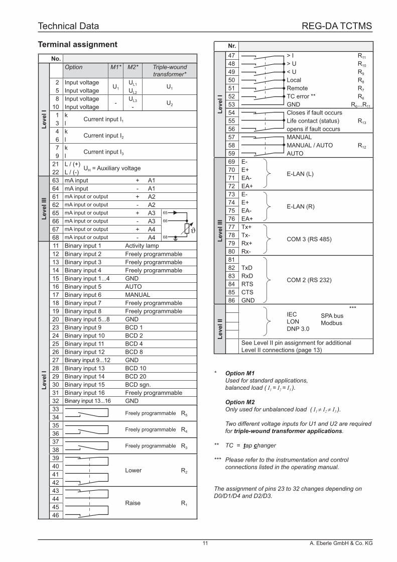
* Option M1 Used for standard applications, balanced load ( I1 = I2 = I3 ).
Option M2 Only used for unbalanced load ( I1 ≠ I2 ≠ I3 ).
Two different voltage inputs for U1 and U2 are required for triple-wound transformer applications.
** TC = tap changer
*** Please refer to the instrumentation and control connections listed in the operating manual.
The assignment of pins 23 to 32 changes depending on D0/D1/D4 and D2/D3.
Terminal assignment
Technical Data REG-DA TCTMS
11 A. Eberle GmbH & Co. KG
SERVICEBLOCKED
F3F3
F2F2
F1F1
F4F4
F5F5
AUTOAUTO REMOTEREMOTE
LOCALLOCAL
ACKACK
MENUMENUESCESC
REG-DAREG-DA a-eberle
Display-Maße67,8 x 67,8 mmX = 114,5Y = 88,5
1 2 3 4 5 6 7 8 9 10
33 34 35 36 37 38 39 40 41 42 43 44 45 46 47 48 49 50 51 52 53 54 55 56 57 58 59 60
11 12 13 14 15 16 17 18 19 20
21 2223 24 25 26 27 28 29 30 31 32
Binary inputs
107108109110 111 112 113100101102103104105106 87 88 89 90 91 92 93 94
1 56 977 78 79 80 81 81 83 84 85 8661 62 63 64 65 66 67 68 69 70 71 72 73 74 75 76 COM 1
Ethernet connection(IEC 61850, IEC 60870-5-104)
Relay outputs
Binary inputs
Level III
Level II
Level I
SERVICEBLOCKED
F3F3
F2F2
F1F1
F4F4
F5F5
AUTOAUTO REMOTEREMOTE
LOCALLOCAL
ACKACK
MENUMENUESCESC
REG-DAREG-DA a-eberle
Display-Maße67,8 x 67,8 mmX = 114,5Y = 88,5
1 2 3 4 5 6 7 8 9 10
33 34 35 36 37 38 39 40 41 42 43 44 45 46 47 48 49 50 51 52 53 54 55 56 57 58 59 60
11 12 13 14 15 16 17 18 19 20
21 22 ON
1 2
23 24 25 26
107108109110 111 112 113100101102103104105106 87 88 89 90 91 92 93 94
1 56 977 78 79 80 81 81 83 84 85 8661 62 63 64 65 66 67 68 69 70 71 72 73 74 75 76 COM 1
Ethernet (IEC 61850, IEC 60870-5-104)
connection
Relay outputs
Binary inputsTap-changepotentiometer input
Level III
Level II
Level I
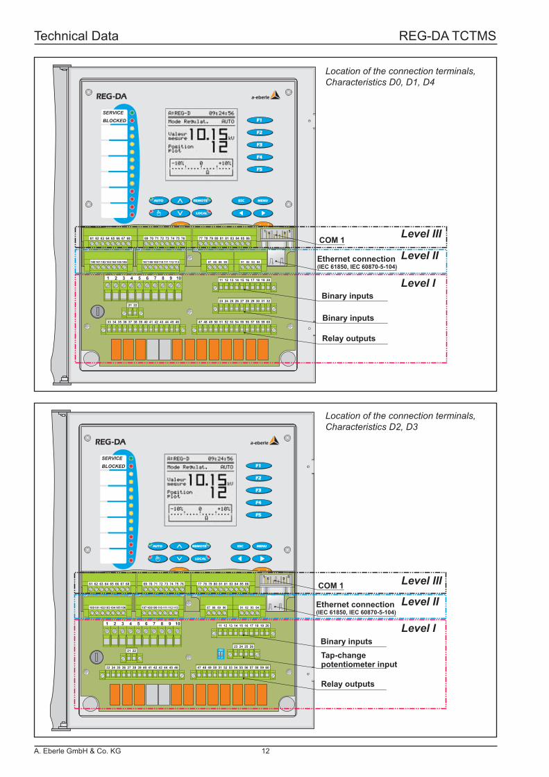
Location of the connection terminals, Characteristics D0, D1, D4
Location of the connection terminals, Characteristics D2, D3
Technical Data REG-DA TCTMS
A. Eberle GmbH & Co. KG 12
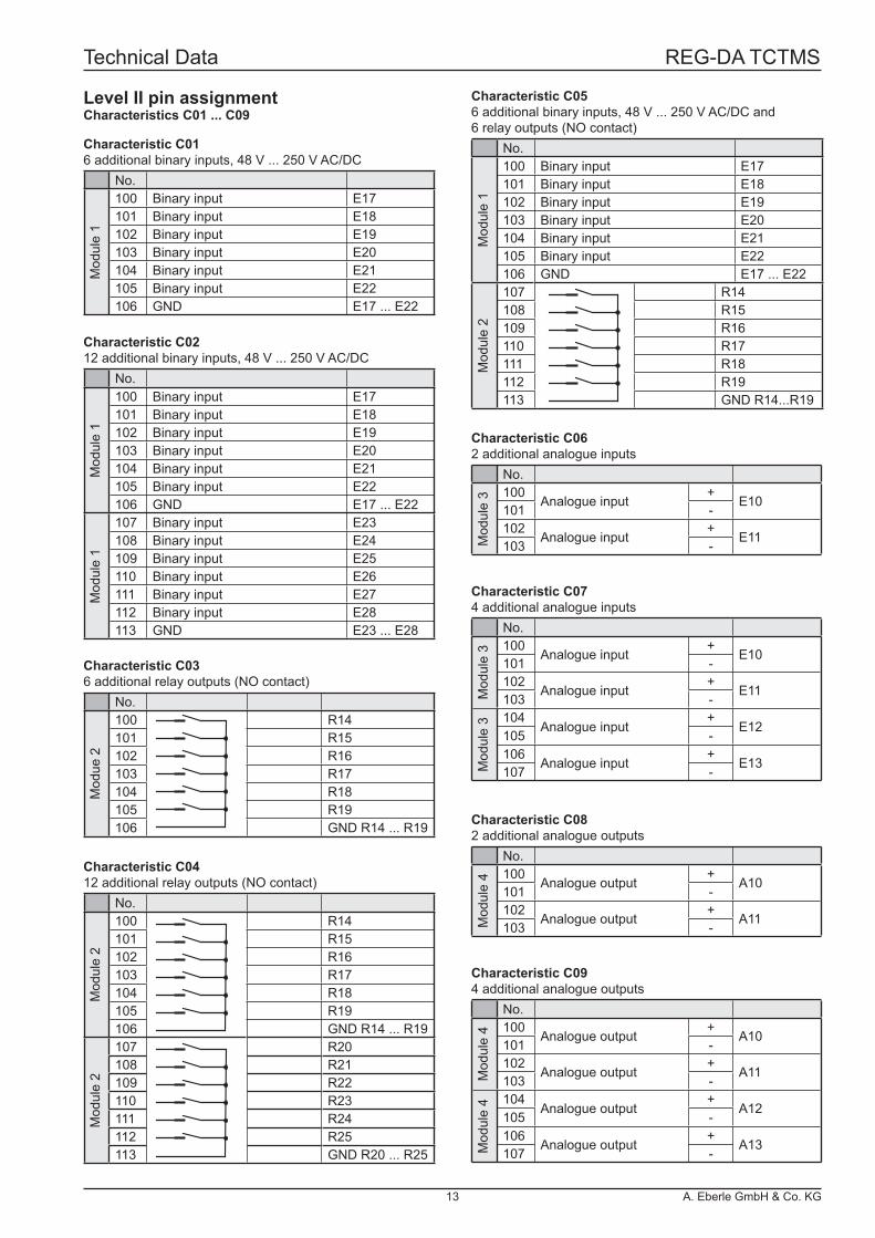
Level II pin assignmentCharacteristics C01 ... C09
Characteristic C016 additional binary inputs, 48 V ... 250 V AC/DC
No.
Mod
ule
1
100 Binary input E17101 Binary input E18102 Binary input E19103 Binary input E20104 Binary input E21105 Binary input E22106 GND E17 ... E22
Characteristic C0212 additional binary inputs, 48 V ... 250 V AC/DC
No.
Mod
ule
1
100 Binary input E17101 Binary input E18102 Binary input E19103 Binary input E20104 Binary input E21105 Binary input E22106 GND E17 ... E22
Mod
ule
1
107 Binary input E23108 Binary input E24109 Binary input E25110 Binary input E26111 Binary input E27112 Binary input E28113 GND E23 ... E28
Characteristic C036 additional relay outputs (NO contact)
No.
Mod
ue 2
100 R14101 R15102 R16103 R17104 R18105 R19106 GND R14 ... R19
Characteristic C0412 additional relay outputs (NO contact)
No.
Mod
ule
2
100 R14101 R15102 R16103 R17104 R18105 R19106 GND R14 ... R19
Mod
ule
2
107 R20108 R21109 R22110 R23111 R24112 R25113 GND R20 ... R25
Characteristic C056 additional binary inputs, 48 V ... 250 V AC/DC and6 relay outputs (NO contact)
No.
Mod
ule
1
100 Binary input E17101 Binary input E18102 Binary input E19103 Binary input E20104 Binary input E21105 Binary input E22106 GND E17 ... E22
Mod
ule
2
107 R14108 R15109 R16110 R17111 R18112 R19113 GND R14...R19
Characteristic C074 additional analogue inputs
No.
Mod
ule
3 100Analogue input
+E10
101 -102
Analogue input+
E11103 -
Mod
ule
3 104Analogue input
+E12
105 -106
Analogue input+
E13107 -
Characteristic C062 additional analogue inputs
No.M
odul
e 3 100
Analogue input+
E10101 -102
Analogue input+
E11103 -
Characteristic C094 additional analogue outputs
No.
Mod
ule
4 100Analogue output
+A10
101 -102
Analogue output+
A11103 -
Mod
ule
4 104Analogue output
+A12
105 -106
Analogue output+
A13107 -
Characteristic C082 additional analogue outputs
No.
Mod
ule
4 100Analogue output
+A10
101 -102
Analogue output+
A11103 -
Technical Data REG-DA TCTMS
13 A. Eberle GmbH & Co. KG
RS2
32C
OM
1
Term
inal
no.
Leve
l
Leve
l
Level
Level
Lege
nd:
optio
nal
E1...E4
TC in op.progr.progr.progr.
AUTOMANUALprogr.progr.E5...E8
Inpu
ts E
1 ...
E8
50...
230
V A
C/D
C
1112
1314
1516
1718
1920
E9...E12
BCD 1
BCD 10BCD 20BCD sgn.progr.E13...E16
Inpu
ts E
9 ...
E16
50...
230
V A
C/D
C
2425
2627
2829
3031
32
BCD 2BCD 4BCD 8
GND
E1E2E3E4
E5E6E7E8GND
GND
E9
E13E14E15E16GND
E10E11E12
23
LCD
µPLE
D
RA
M/R
OM
128
x 12
8 D
OTS
disp
lay
Key
boar
d
CLO
CK
U1
2 5U
U2
8 10U
I11 3
I
I24 6
I
I37 9
I
L / (
+)21 22
L / (
-)
Cha
ract
eris
tic M
2
Cha
ract
eris
tic M
2
UH
61
23
45
78
9
GND
CTSTXDRTSRXD
Anal
ogue
inpu
ts a
nd o
utpu
ts
6162
6566
6768
A2A3
A4
6364
A1 mA input
Input or output
Cha
ract
eris
ticl E
91.
..99
+
Dou
ble
mod
ulel
+
+
+
-
-
-
-
mA input
Input or output
Input or output
Input or output
Input or output
Input or output
+ +
+ +
- -
- -*
R2
R3
prog
r.R
4
prog
r.R
5
343536373839404142434445
R1
46
GN
DR
6...R
11
R6
TC
faul
tR
7 R
emot
eR
8 L
ocal
R9
<UR
10>U
R11
>I
52515049484753575859545556
MA
NU
AL
Life
con
tact
(Sta
tus) prog
r.
Relay outputs48...250 V AC/DC
Relay outputs48...250 V AC/DC
Low
er
Rai
se
33
R12
Clo
ses
MAN
UAL
/ AUT
O
R13
Ope
ns
AU
TO
CTSRTS C
OM
2R
S232
CO
M 3
RS4
85
8584
8683
8280
7978
77
GNDRxDTxD
Rx -Rx +Tx -Tx +
E +EA -EA +
6970
7172
7374
7576
E-LA
NL
E-LA
NR
E -
E +EA -EA +
E -
81
IEC
LON
DN
P 3.
0M
OD
BUS
FSM
AST IE
CD
NP
3.0
LON
SPAB
US
100
113
Addi
tiona
lin
puts
and
out
puts
Cha
ract
eris
tic C
01...
C09
(See
pin
ass
ignm
ent
on p
age
13)
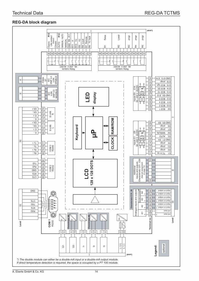
REG-DA block diagram
*) The double module can either be a double-mA input or a double-mA output module.If direct temperature detection is required, the space is occupied by a PT 100 module.
Technical Data REG-DA TCTMS
A. Eberle GmbH & Co. KG 14
COM1AUTO MENUESC
F1
F2
F3
F4
F5
Status< U
> U> I
REG - D a. eberle gmbh
COM1
Status
a. eberle gmbhPAN - D
AUTO
< U1
> U2
> I
>> U3
>> U4
Auslösung
Störung
StörungRegler
Stufenschalter
Leitungsschalter
Rückführung
Lauflampe
läuft
Test
a. eberle gmbh
ANA-D
a. eberle gmbh
ANA-D
a. eberle gmbh
ANA-D
a. eberle gmbh
ANA-D
a. eberle gmbh
ANA-D
RS232
RS485
Fibre optic
cable
IEC 61850IEC 60850-5-101/103/104MODBUS, SPABUS,LONMark, DNP 3.00
E-LAN
E-LAN
REG-BO
EOR-D
E-LAN
< 5 km
REG-PCREG-BO
Remote control device
BCD-CODE
REG-DPPAN-D REG-ST
REG-F(X)REG-S
BCD-CODE (Tap-change position)
COM3RS485
BIN-D ANA-D
WinREG
Windows 95Windows 98Windows NTWindows 2000Windows XP
REGSys™ - Overview
MMU-D
E-LANRS485
COM1RS232
PQI-D
RS232
REG-D
REG-DAREG - DE
C OM1
a. eberle gm bh
AU TO MENUESC
F1
F2
F3
F4
F5
StatusM
A: REG-DE 12:34:00
Re gelnIpos = 98 .0 A +4.5 AV =
Uo = 0.85 % 2.0 Ad =
0.1
1
10
20A I m in I max 200A
U o
ABGE STIMMT
a. eberle gmbhPQI-D
COM1
Status
Reset
1
23
4
a. eber le gmbhEOR-D
C OM1
Status
Reset
1
23
4
a. ebe r le gmbhEOR-D
COM1
Status
Reset
1
23
4
a. ebe r le gmbhEOR-D
COM1
Status
Reset
12
34
a. ebe r le gmbhEOR-D
COM1
Status
Reset
12
34
a. eberle gmbhMMU-D
C OM1
Status
Reset
1
23
4
Ethernet
E-LAN
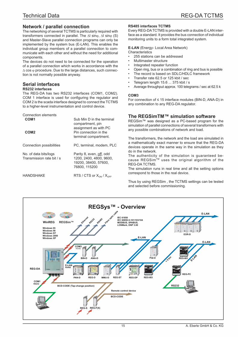
Network / parallel connectionThe networking of several TCTMS is particularly required with transformers connected in parallel. The ∆I sinϕ, ∆I sinϕ (S) and Master-Slave parallel connection programs can only be implemented by the system bus (E-LAN). This enables the individual group members of a parallel connection to com-municate with each other and without the need for additional components.The devices do not need to be connected for the operation of a parallel connection which works in accordance with the ∆ cos ϕ procedure. Due to the large distances, such connec-tion is not normally possible anyway.
Serial interfacesRS232 interfacesThe REG-DA has two RS232 interfaces (COM1, COM2). COM 1 interface is used for confi guring the regulator and COM 2 is the scada interface designed to connect the TCTMS to a higher-level instrumentation and control device.
Connection elements COM1 Sub Min D in the terminal compartment, pin assignment as with PC COM2 Pin connection in the terminal compartment.
Connection possibilities PC, terminal, modem, PLC
No. of data bits/logs Parity 8, even, off, oddTransmission rate bit / s 1200, 2400, 4800, 9600, 19200, 38400, 57600, 76800, 115200
HANDSHAKE RTS / CTS or XON / XOFF
RS485 interfaces TCTMSEvery REG-DA TCTMS is provided with a double E-LAN inter-face as a standard. It provides the bus connection of individual monitoring units to a form total integrated system.
E-LAN (Energy- Local Area Network)Characteristics• 255 stations can be addressed• Multimaster structure• Integrated repeater function• Open ring, bus or a combination of ring and bus is possible• The record is based on SDLC/HDLC framework• Transfer rate 62.5 or 125 kbit / sec• Telegram length 15.6 ... 375 kbit / s• Average throughput approx. 100 telegrams / sec at 62.5 k
COM3For connection of ≤ 15 interface modules (BIN-D, ANA-D) in any combination to any REG-DA regulator.
The REGSimTM™ simulation softwareREGSim™ was designed as a PC-based program for the simulation of parallel connections of several transformers with any possible combinations of network and load.
The transformers, the network and the load are simulated in a mathematically exact manner to ensure that the REG-DA devices operate in the same way in the simulation as they do in the network.The authenticity of the simulation is guaranteed be-cause REGSimTM uses the original algorithm of the REG-DA TCTMS.The simulation runs in real time and all the setting options correspond to those in the real device.
Thus by using REGSim , the TCTMS settings can be tested and selected before commissioning.
Technical Data REG-DA TCTMS
15 A. Eberle GmbH & Co. KG
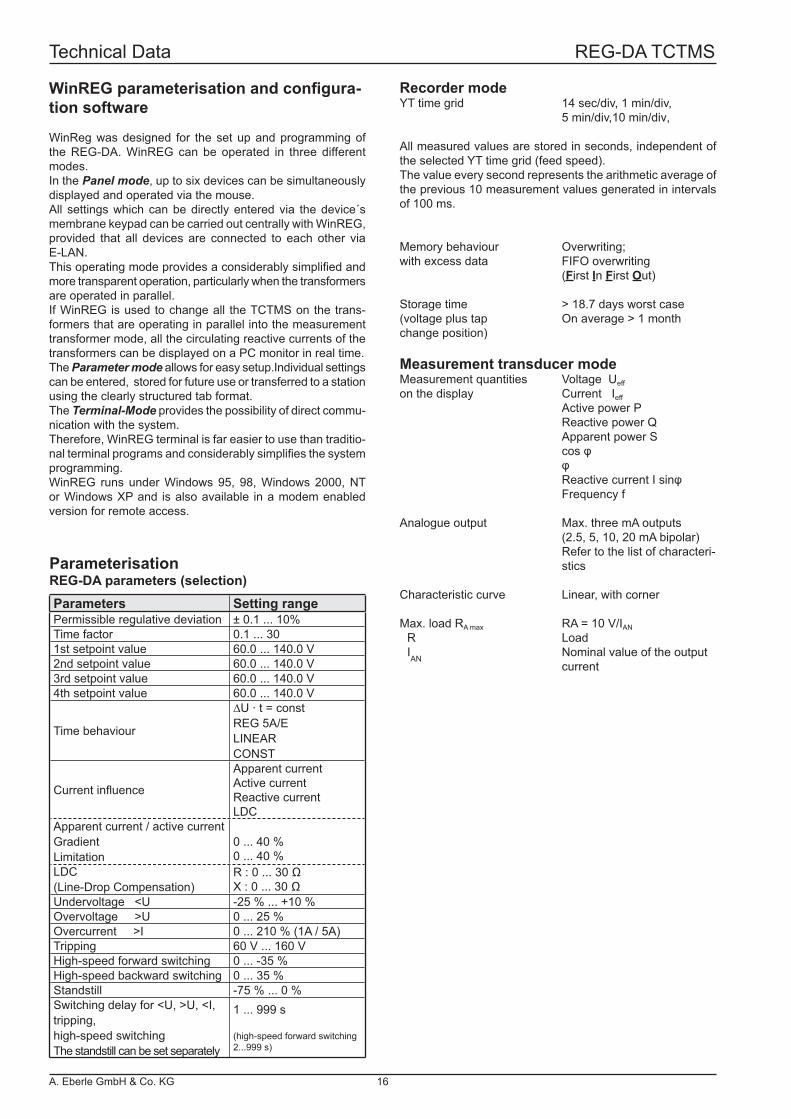
Parameterisation
Recorder modeYT time grid 14 sec/div, 1 min/div, 5 min/div,10 min/div,
All measured values are stored in seconds, independent of the selected YT time grid (feed speed).The value every second represents the arithmetic average of the previous 10 measurement values generated in intervals of 100 ms.
Memory behaviour Overwriting;with excess data FIFO overwriting (First In First Out)
Storage time > 18.7 days worst case(voltage plus tap On average > 1 monthchange position)
Measurement transducer modeMeasurement quantities Voltage Ueff
on the display Current Ieff
Active power P Reactive power Q Apparent power S cos φ φ Reactive current I sinφ Frequency f
Analogue output Max. three mA outputs (2.5, 5, 10, 20 mA bipolar) Refer to the list of characteri- stics
Characteristic curve Linear, with corner
Max. load RA max RA = 10 V/IAN
R Load
IAN
Nominal value of the output current
REG-DA parameters (selection)
WinREG parameterisation and confi gura-tion software
WinReg was designed for the set up and programming of the REG-DA. WinREG can be operated in three different modes.In the Panel mode, up to six devices can be simultaneously displayed and operated via the mouse.All settings which can be directly entered via the device´s membrane keypad can be carried out centrally with WinREG, provided that all devices are connected to each other via E-LAN.This operating mode provides a considerably simplifi ed and more transparent operation, particularly when the transformers are operated in parallel.If WinREG is used to change all the TCTMS on the trans-formers that are operating in parallel into the measurement transformer mode, all the circulating reactive currents of the transformers can be displayed on a PC monitor in real time.The Parameter mode allows for easy setup.Individual settings can be entered, stored for future use or transferred to a station using the clearly structured tab format.The Terminal-Mode provides the possibility of direct commu-nication with the system.Therefore, WinREG terminal is far easier to use than traditio-nal terminal programs and considerably simplifi es the system programming.WinREG runs under Windows 95, 98, Windows 2000, NT or Windows XP and is also available in a modem enabled version for remote access.
Parameters Setting rangePermissible regulative deviation ± 0.1 ... 10%Time factor 0.1 ... 301st setpoint value 60.0 ... 140.0 V2nd setpoint value 60.0 ... 140.0 V3rd setpoint value 60.0 ... 140.0 V4th setpoint value 60.0 ... 140.0 V
Time behaviour
∆U · t = constREG 5A/ELINEARCONST
Current infl uence
Apparent currentActive currentReactive currentLDC
Apparent current / active currentGradientLimitation
0 ... 40 %0 ... 40 %
LDC(Line-Drop Compensation)
R : 0 ... 30 ΩX : 0 ... 30 Ω
Undervoltage <U -25 % ... +10 %Overvoltage >U 0 ... 25 %Overcurrent >I 0 ... 210 % (1A / 5A)Tripping 60 V ... 160 VHigh-speed forward switching 0 ... -35 %High-speed backward switching 0 ... 35 %Standstill -75 % ... 0 %Switching delay for <U, >U, <I, tripping,high-speed switchingThe standstill can be set separately
1 ... 999 s
(high-speed forward switching 2...999 s)
Technical Data REG-DA TCTMS
A. Eberle GmbH & Co. KG 16
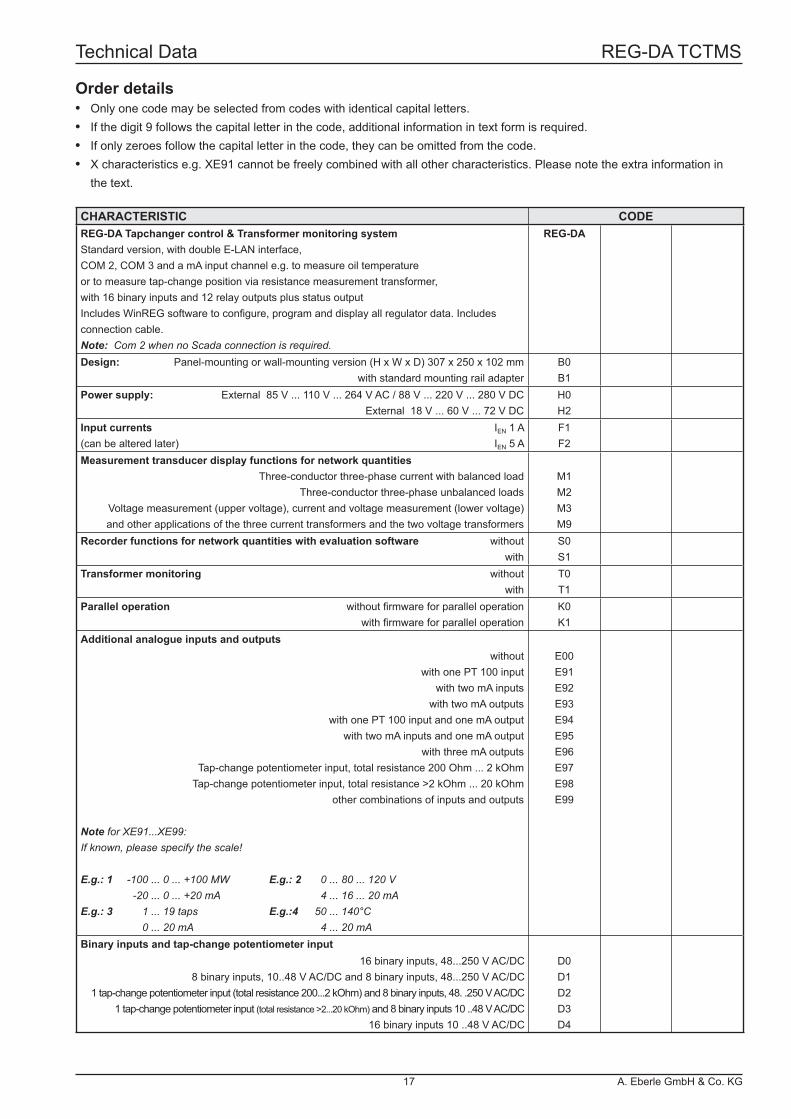
CHARACTERISTIC CODEREG-DA Tapchanger control & Transformer monitoring systemStandard version, with double E-LAN interface,COM 2, COM 3 and a mA input channel e.g. to measure oil temperatureor to measure tap-change position via resistance measurement transformer,with 16 binary inputs and 12 relay outputs plus status outputIncludes WinREG software to confi gure, program and display all regulator data. Includes connection cable.Note: Com 2 when no Scada connection is required.
REG-DA
Design: Panel-mounting or wall-mounting version (H x W x D) 307 x 250 x 102 mm with standard mounting rail adapter
B0B1
Power supply: External 85 V ... 110 V ... 264 V AC / 88 V ... 220 V ... 280 V DCExternal 18 V ... 60 V ... 72 V DC
H0H2
Input currents(can be altered later)
IEN 1 AIEN 5 A
F1F2
Measurement transducer display functions for network quantitiesThree-conductor three-phase current with balanced load
Three-conductor three-phase unbalanced loadsVoltage measurement (upper voltage), current and voltage measurement (lower voltage)and other applications of the three current transformers and the two voltage transformers
M1M2M3M9
Recorder functions for network quantities with evaluation software withoutwith
S0S1
Transformer monitoring withoutwith
T0T1
Parallel operation without fi rmware for parallel operationwith fi rmware for parallel operation
K0K1
Additional analogue inputs and outputswithout
with one PT 100 inputwith two mA inputs
with two mA outputswith one PT 100 input and one mA output
with two mA inputs and one mA outputwith three mA outputs
Tap-change potentiometer input, total resistance 200 Ohm ... 2 kOhmTap-change potentiometer input, total resistance >2 kOhm ... 20 kOhm
other combinations of inputs and outputs
Note for XE91...XE99:If known, please specify the scale!
E.g.: 1 -100 ... 0 ... +100 MW E.g.: 2 0 ... 80 ... 120 V -20 ... 0 ... +20 mA 4 ... 16 ... 20 mAE.g.: 3 1 ... 19 taps E.g.:4 50 ... 140°C 0 ... 20 mA 4 ... 20 mA
E00E91E92E93E94E95E96E97E98E99
Binary inputs and tap-change potentiometer input16 binary inputs, 48...250 V AC/DC
8 binary inputs, 10..48 V AC/DC and 8 binary inputs, 48...250 V AC/DC 1 tap-change potentiometer input (total resistance 200...2 kOhm) and 8 binary inputs, 48. .250 V AC/DC
1 tap-change potentiometer input (total resistance >2...20 kOhm) and 8 binary inputs 10 ..48 V AC/DC 16 binary inputs 10 ..48 V AC/DC
D0D1D2D3D4
Order details• Only one code may be selected from codes with identical capital letters.• If the digit 9 follows the capital letter in the code, additional information in text form is required.• If only zeroes follow the capital letter in the code, they can be omitted from the code.• X characteristics e.g. XE91 cannot be freely combined with all other characteristics. Please note the extra information in the text.
Technical Data REG-DA TCTMS
17 A. Eberle GmbH & Co. KG

Characteristic CODEREG-DA
Level II: additional inputs and outputswithout
with 6 binary inputs 48 V...250 V AC/DCwith 12 binary inputs 48 V...250 V AC/DC
with 6 relay outputswith 12 relay outputs
with 6 binary inputs and 6 relay outputswith 2 analogue inputswith 4 analogue inputs
with 2 analogue outputswith 4 analogue outputs
other combinations of 6 inputs, 6 outputs, 2 analogue inputs, 2 analogue outputs
Note about C90: Two slots are normally available on Level II.Each terminal can be equipped with either 6 binary inputs, 6 binary outputs or an analogue module.Each analogue module has either 2 inputs or 2 outputs.The regulator can be equipped with 4 additional modules if no instrumentation and control connections (XW90, 91 or L1, L9) are used.
C00C01C02C03C04C05C06C07C08C09C90
Integrated instrumentation and control connections according to IEC61850 or IEC 60870- 5-104without
IEC 60850 - 5 - 104 (extended with group of characteristics “G”)Note: please enter target system if to be connected according to IEC 60850-5-104
IEC 61850 (extended with group of characteristics “G”)
XW00XW90
XW91
Integrated instrumentation and control connections according to IEC 60870- 5-101/ ..-103, DNP…without (extended with group of characteristics “G”)
for the instrumentation and control connection of a REG-DAor the instrumentation and control connection of multiple systems (REG-D/DA/DP, etc.)
Note: L9 can only be combined with characteristics XW90, Z15 to Z19 and Z91.
L0L1L9
Type of connection: Copper RS 232
RS 485, 2-wire operation onlyV10V11
Fibre optic cable with FSMA connectionGlass fi bre (wavelength 800...900 nm, range 2000 m)
plastic (wavelength 620...680 nm, range 50 m)V13V15
Fibre optic cable with ST connectionGlass fi bre (wavelength 800...900 nm, range 2000 m)
plastic (wavelength 620...680 nm, range 50 m)V17V19
Protokoll:IEC60870-5-103 for ABB
IEC60870-5-103 for ArevaIEC60870-5-103 for SAT
IEC60870-5-103 f0r Siemens (LSA/SAS)IEC60870-5-103 f0r Sprecher Automation
IEC60870-5-103 for other
IEC60870-5-101 for ABBIEC60870-5-101 for IDSIEC60870-5-101 for SAT
IEC60870-5-101 for Siemens (LSA/SAS)IEC60870-5-101 for other
DNP 3.00LONMarkSPABUS
MODBUS RTU
Z10Z11Z12Z13Z14Z90
Z15Z17Z18Z19Z91
Z20Z21Z22Z23
Characteristics continued
Technical Data REG-DA TCTMS
A. Eberle GmbH & Co. KG 18
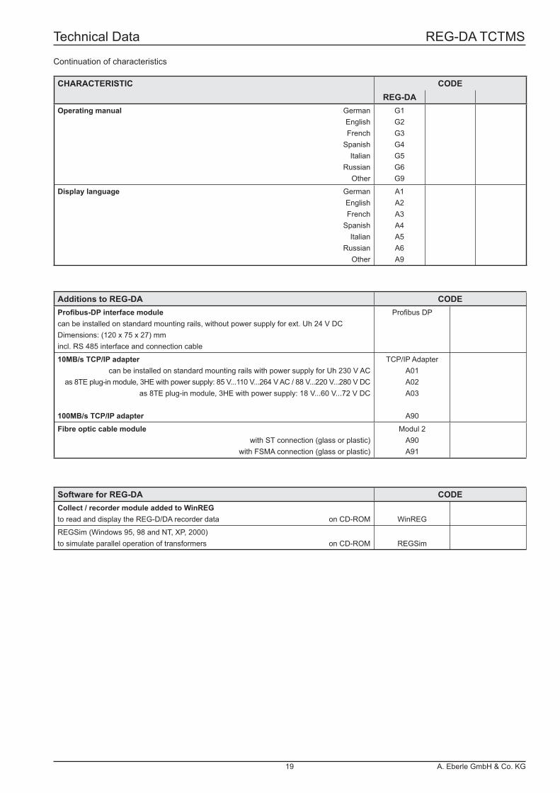
CHARACTERISTIC CODEREG-DA
Operating manual GermanEnglishFrench
SpanishItalian
RussianOther
G1G2G3G4G5G6G9
Display language GermanEnglishFrench
SpanishItalian
RussianOther
A1A2A3A4A5A6A9
Additions to REG-DA CODEProfi bus-DP interface modulecan be installed on standard mounting rails, without power supply for ext. Uh 24 V DCDimensions: (120 x 75 x 27) mmincl. RS 485 interface and connection cable
Profi bus DP
10MB/s TCP/IP adaptercan be installed on standard mounting rails with power supply for Uh 230 V AC
as 8TE plug-in module, 3HE with power supply: 85 V...110 V...264 V AC / 88 V...220 V...280 V DC as 8TE plug-in module, 3HE with power supply: 18 V...60 V...72 V DC
100MB/s TCP/IP adapter
TCP/IP AdapterA01A02A03
A90
Fibre optic cable modulewith ST connection (glass or plastic)
with FSMA connection (glass or plastic)
Modul 2A90A91
Software for REG-DA CODECollect / recorder module added to WinREGto read and display the REG-D/DA recorder data on CD-ROM WinREG
REGSim (Windows 95, 98 and NT, XP, 2000)to simulate parallel operation of transformers on CD-ROM REGSim
Continuation of characteristics
Technical Data REG-DA TCTMS
19 A. Eberle GmbH & Co. KG
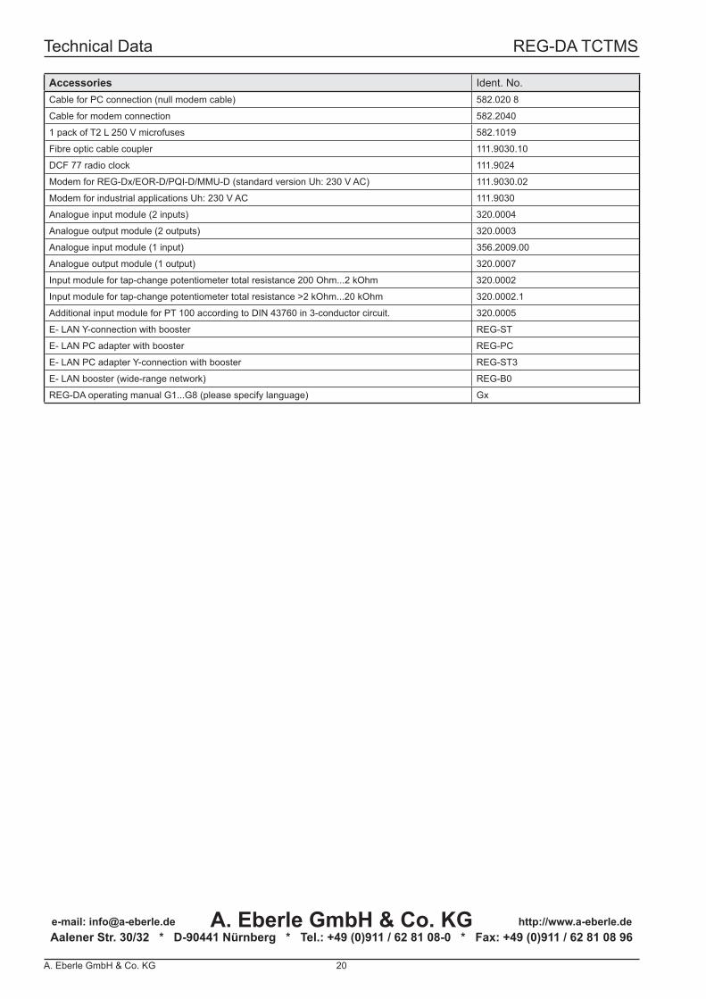
Accessories Ident. No.Cable for PC connection (null modem cable) 582.020 8
Cable for modem connection 582.2040
1 pack of T2 L 250 V microfuses 582.1019
Fibre optic cable coupler 111.9030.10
DCF 77 radio clock 111.9024
Modem for REG-Dx/EOR-D/PQI-D/MMU-D (standard version Uh: 230 V AC) 111.9030.02
Modem for industrial applications Uh: 230 V AC 111.9030
Analogue input module (2 inputs) 320.0004
Analogue output module (2 outputs) 320.0003
Analogue input module (1 input) 356.2009.00
Analogue output module (1 output) 320.0007
Input module for tap-change potentiometer total resistance 200 Ohm...2 kOhm 320.0002
Input module for tap-change potentiometer total resistance >2 kOhm...20 kOhm 320.0002.1
Additional input module for PT 100 according to DIN 43760 in 3-conductor circuit. 320.0005
E- LAN Y-connection with booster REG-ST
E- LAN PC adapter with booster REG-PC
E- LAN PC adapter Y-connection with booster REG-ST3
E- LAN booster (wide-range network) REG-B0
REG-DA operating manual G1...G8 (please specify language) Gx
A. Eberle GmbH & Co. KGAalener Str. 30/32 * D-90441 Nürnberg * Tel.: +49 (0)911 / 62 81 08-0 * Fax: +49 (0)911 / 62 81 08 96e-mail: [email protected] http://www.a-eberle.de
Technical Data REG-DA TCTMS
A. Eberle GmbH & Co. KG 20