Embed Size (px)
Citation preview
International Journal of Research in Advent Technology (IJRAT) (E-ISSN: 2321-9637)
Special Issue National Conference “CONVERGENCE 2017”, 09 th April 2017
119
Transformer Protection by Using Arduino with GSM Modem
Prof. R. B. Pandhare1,Mr. ParmanandWaghmare2, Ms. Ashvini Gawande3, Mr. Gopal Bahekar4, Ms. Rekha Ghate5
Department of Electrical Engineering1,2,3,4,5, faculty of Electrical Engineering1 Students of Electrical Engineering2,3,4,5
Email: [email protected],[email protected]@gmail.com3,bahekargopal16@gam
il.com4, [email protected] Abstract:-Distribution transformer is a main element for electrical energy transfer in electrical power systems. Prevent the distribution transformer damage due to the overloading currents, over-heatingof transformers oiland high voltage spikes. So, relevant protection of transformer is very crucial for continuity ofpower supply. In this protective strategy is implemented by using of Arduinocontroller that is cost powerful deviceandtremendous high speed with high accuracy. The controller sense the temperature of transformer and current of load continuously. The rating of voltage and currentreaches from its pre-setvalues, protection scheme operates and trips the load. As temperature reaches to threshold value set in system, a fan would turn on for the cooling of the heated transformer. During the testing a special type of transformer that is i.e. autotransformer is used to vary the input voltage of the transformer to generate over voltage and under voltage fault. To occur the over current fault we increase load by using bulbs. If any emergency or aberrantconditions occur the system sends information through SMS to the mobile phones, by using GSMModem. At the end, successful results have been justifying the proposed technique and identify problems before any failure. Keywords:-Distribution transformer, potential transformer, Current transformer, Arduino, GSM, Relay.
1. INTRODUCTION
Distribution transformer is electrical equipment which is utilized to step down the voltage without change in frequency. In this paper a protection system has been fabricated in such a way that system is monitoring the real time based, operating flexible of the transformer continuously and these parameters are viewed on the LCD display. In the LCD display unit we can view the continuous parametric information of transformer. In this research work a potential transformer is used for step down the line voltage for measuring purposes and current transformer is acting as a current sensor. The C.T. place in series and P.T. is shunt to the transformer.Thermistor is utilized to measure the temperature of transformer oil. Relays are used to carry out the tripping mechanism. Voltage and currents aremeasured using A/D converter of microcontroller. A/Dconverter converts the values of analog current and voltage value to the digital value. Then according to the code, values are compared with the preset values in the controller if excess in any parameter occur a relay would trip the transformer upon exceeding the limit of current and voltage. If temperature increases from preset value, a fan would be turn on using relay. The voltage, temperature and current values are displayed on the LCD. It is also has the advantages of significant cost savings, power consumption and greater reliability. In this system, Arduino microcontroller is used to monitor cases of electrical faults and communicate to a switch to detachthe transformer from the system.
2. LITERATURE REVIEW
Electric Power system an electric Power system refers to a network that constitutes electrical components/machines used in the supply, transmission and digestion of electric power. The figure shows below clarification a complete power electric system. It involves generation, transmission and distribution of electric power to various categories of consumers. The generation plant is normally located far from the load center.
There are different levels of electric power consumption depending on the motive for which a customer uses electricity. Electrical power consumers may be commercial, domestic orindustrial [3]. These consumers require different levels of electric power supply. In order to meet their specific requirement, certain devices that adjust the voltage levels accordingly have to be used. Some of those components include prevent devices, capacitor banks, step down and step up transformersetc.
International Journal of Research in Advent Technology (IJRAT) (E-ISSN: 2321-9637)
Special Issue National Conference “CONVERGENCE 2017”, 09 th April 2017
120
Figure1:-Generation, transmission and distribution of
electrical power 3. PROBLEM STATEMENT Transformer is electrical element that changes the voltage from one level to other level without change in frequency. Transformer is more expensive device in power system. As the load increase at secondary winding of the transformer form its rated value [1]. Due to short circuit or instantly increase in load can cause overloading, over-voltages and overheating that can damage the insulation of transformer windings and severe damage can be occur on the secondary side. The various types of faults that cause the transformer failures are winding faults, faults due to over currents, over voltage faults, earthing faults, insulation failure faults and bushing flashover faults [4]. So, for overcome above problems a reliable and speedy protection with more accuracy is needed. In this paper a protection scheme is purposed that addresses the above stated problems. Power system protection is a vital consideration in the design of an electrical power system. There is need to protect electrical power components from dangerous faults. This is warranted by the need to improve the life of the components, avoid dispersible expenditure in frequent replacement of obsolete components and to ensure that there is a continuous supply of power to serve the needs of the ever growing economy. This paper therefore seeks to design a microcontroller based system that will intelligently monitor faults and prompt a safety measure to protect the power transformer in case of power overload.
4. PROPOSED TECHNIQUE
Methodology of purposed protection scheme is shown in following figure (2) with the help of block diagrams. The brain of the scheme is Arduino board [5]. Detailed description and circuit of each block is given below.
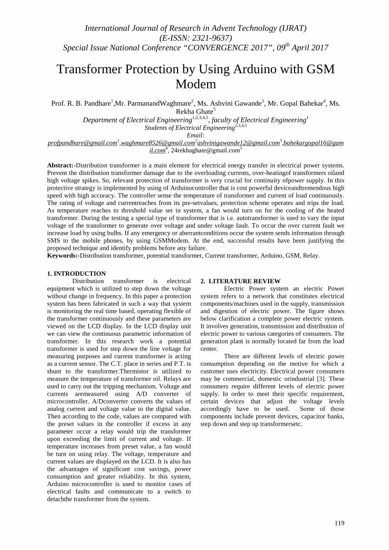
Figure 2:- Block Diagram.
4.1 Current Transformer (C.T.) The C.T. is act as current sensor which is
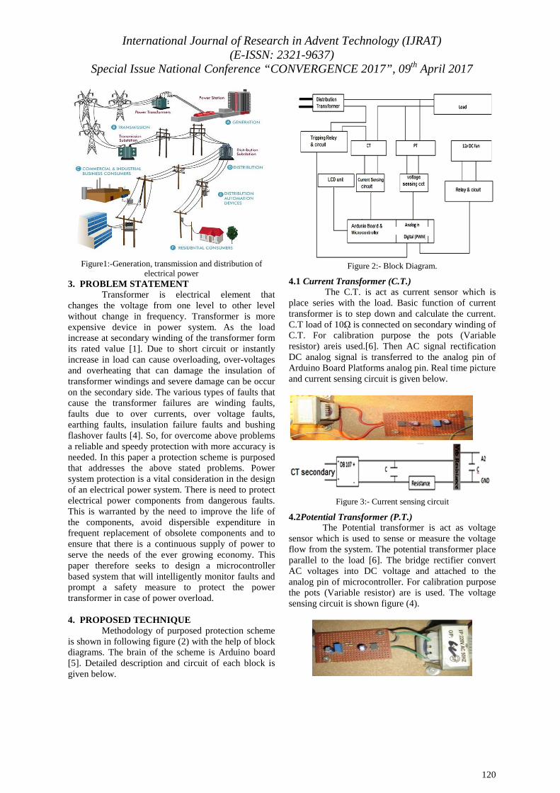
place series with the load. Basic function of current transformer is to step down and calculate the current. C.T load of 10ῼ is connected on secondary winding of C.T. For calibration purpose the pots (Variable resistor) areis used.[6]. Then AC signal rectification DC analog signal is transferred to the analog pin of Arduino Board Platforms analog pin. Real time picture and current sensing circuit is given below.
Figure 3:- Current sensing circuit
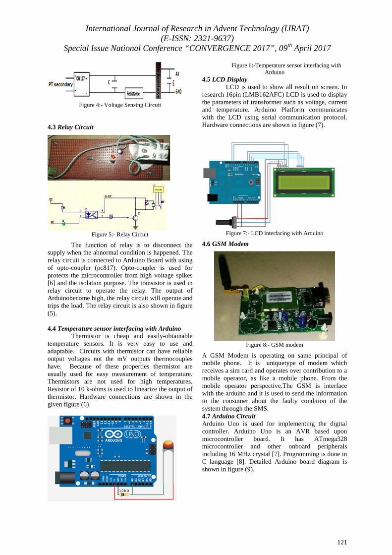
4.2Potential Transformer (P.T.) The Potential transformer is act as voltage
sensor which is used to sense or measure the voltage flow from the system. The potential transformer place parallel to the load [6]. The bridge rectifier convert AC voltages into DC voltage and attached to the analog pin of microcontroller. For calibration purpose the pots (Variable resistor) are is used. The voltage sensing circuit is shown figure (4).
International Journal of Research in Advent Technology (IJRAT) (E-ISSN: 2321-9637)
Special Issue National Conference “CONVERGENCE 2017”, 09 th April 2017
121
Figure 4:- Voltage Sensing Circuit
4.3 Relay Circuit
Figure 5:- Relay Circuit
The function of relay is to disconnect the supply when the abnormal condition is happened. The relay circuit is connected to Arduino Board with using of opto-coupler (pc817). Opto-coupler is used for protects the microcontroller from high voltage spikes [6] and the isolation purpose. The transistor is used in relay circuit to operate the relay. The output of Arduinobecome high, the relay circuit will operate and trips the load. The relay circuit is also shown in figure (5).
4.4 Temperature sensor interfacing with Arduino
Thermistor is cheap and easily-obtainable temperature sensors. It is very easy to use and adaptable. Circuits with thermistor can have reliable output voltages not the mV outputs thermocouples have. Because of these properties thermistor are usually used for easy measurement of temperature. Thermistors are not used for high temperatures. Resistor of 10 k-ohms is used to linearize the output of thermistor. Hardware connections are shown in the given figure (6).
Figure 6:-Temperature sensor interfacing with Arduino
4.5 LCD Display LCD is used to show all result on screen. In
research 16pin (LMB162AFC) LCD is used to display the parameters of transformer such as voltage, current and temperature. Arduino Platform communicates with the LCD using serial communication protocol. Hardware connections are shown in figure (7).
Figure 7:- LCD interfacing with Arduino
4.6 GSM Modem
Figure 8:- GSM modem
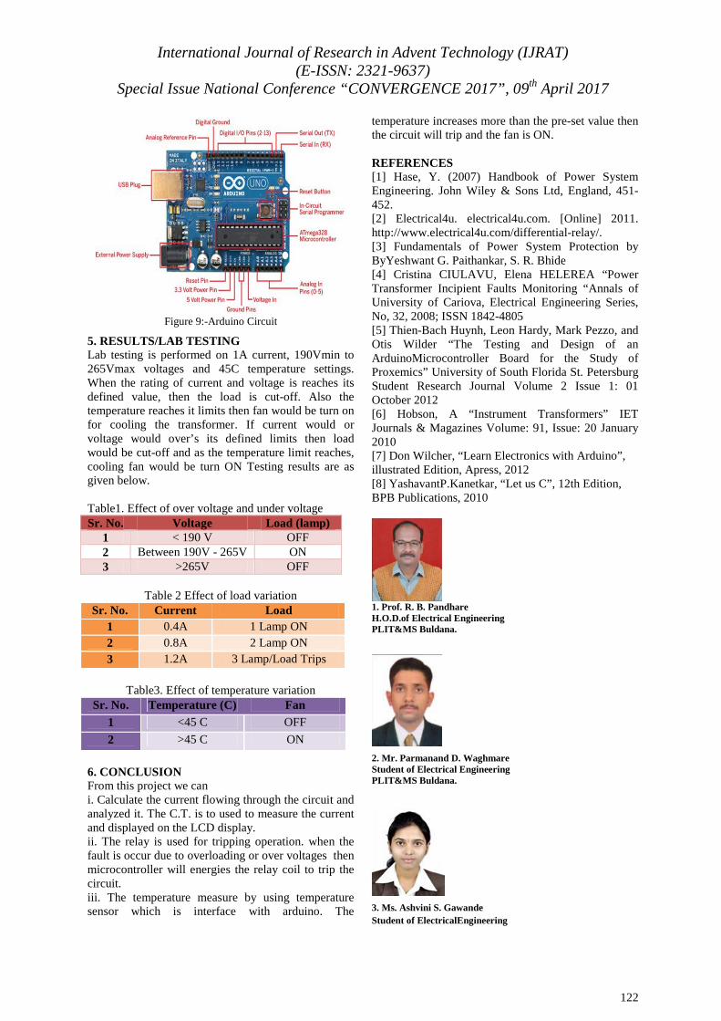
A GSM Modem is operating on same principal of mobile phone. It is uniquetype of modem which receives a sim card and operates over contribution to a mobile operator, as like a mobile phone. From the mobile operator perspective.The GSM is interface with the arduino and it is used to send the information to the consumer about the faulty condition of the system through the SMS. 4.7 Arduino Circuit Arduino Uno is used for implementing the digital controller. Arduino Uno is an AVR based upon microcontroller board. It has ATmega328 microcontroller and other onboard peripherals including 16 MHz crystal [7]. Programming is done in C language [8]. Detailed Arduino board diagram is shown in figure (9).
International Journal of Research in Advent Technology (IJRAT) (E-ISSN: 2321-9637)
Special Issue National Conference “CONVERGENCE 2017”, 09 th April 2017
122
Figure 9:-Arduino Circuit
5. RESULTS/LAB TESTING Lab testing is performed on 1A current, 190Vmin to 265Vmax voltages and 45C temperature settings. When the rating of current and voltage is reaches its defined value, then the load is cut-off. Also the temperature reaches it limits then fan would be turn on for cooling the transformer. If current would or voltage would over’s its defined limits then load would be cut-off and as the temperature limit reaches, cooling fan would be turn ON Testing results are as given below. Table1. Effect of over voltage and under voltage Sr. No. Voltage Load (lamp)
1 < 190 V OFF 2 Between 190V - 265V ON 3 >265V OFF
Table 2 Effect of load variation
Sr. No. Current Load 1 0.4A 1 Lamp ON 2 0.8A 2 Lamp ON 3 1.2A 3 Lamp/Load Trips
Table3. Effect of temperature variation
Sr. No. Temperature (C) Fan 1 <45 C OFF
2 >45 C ON
6. CONCLUSION From this project we can i. Calculate the current flowing through the circuit and analyzed it. The C.T. is to used to measure the current and displayed on the LCD display. ii. The relay is used for tripping operation. when the fault is occur due to overloading or over voltages then microcontroller will energies the relay coil to trip the circuit. iii. The temperature measure by using temperature sensor which is interface with arduino. The
temperature increases more than the pre-set value then the circuit will trip and the fan is ON. REFERENCES [1] Hase, Y. (2007) Handbook of Power System Engineering. John Wiley & Sons Ltd, England, 451-452. [2] Electrical4u. electrical4u.com. [Online] 2011. http://www.electrical4u.com/differential-relay/. [3] Fundamentals of Power System Protection by ByYeshwant G. Paithankar, S. R. Bhide [4] Cristina CIULAVU, Elena HELEREA “Power Transformer Incipient Faults Monitoring “Annals of University of Cariova, Electrical Engineering Series, No, 32, 2008; ISSN 1842-4805 [5] Thien-Bach Huynh, Leon Hardy, Mark Pezzo, and Otis Wilder “The Testing and Design of an ArduinoMicrocontroller Board for the Study of Proxemics” University of South Florida St. Petersburg Student Research Journal Volume 2 Issue 1: 01 October 2012 [6] Hobson, A “Instrument Transformers” IET Journals & Magazines Volume: 91, Issue: 20 January 2010 [7] Don Wilcher, “Learn Electronics with Arduino”, illustrated Edition, Apress, 2012 [8] YashavantP.Kanetkar, “Let us C”, 12th Edition, BPB Publications, 2010
1. Prof. R. B. Pandhare H.O.D.of Electrical Engineering PLIT&MS Buldana.
2. Mr. Parmanand D. Waghmare Student of Electrical Engineering PLIT&MS Buldana.
3. Ms. Ashvini S. Gawande Student of ElectricalEngineering

International Journal of Research in Advent Technology (IJRAT) (E-ISSN: 2321-9637)
Special Issue National Conference “CONVERGENCE 2017”, 09 th April 2017
123
PLIT&MS Buldana.
4. Mr. Gopal V. Bahekar Student of ElectricalEngineering PLIT&MS Buldana.
4. MsRekha S. Ghate Student of Electrical Engineering PLIT&MS Buldana.