Embed Size (px)
Citation preview

1
ABSTRACT
2
ABSTRACT
An embedded system is a special-purpose computer system designed to perform a
dedicated function. Since the system is dedicated to specific tasks, design engineers can
optimize it, reducing the size and cost of the product. Embedded system comprises of
both hardware and software. Embedded system is fast growing technology in various
fields like industrial automation, home appliances, automobiles, aeronautics etc.
Embedded technology uses PC or a controller to do the specified task and the
programming is done using assembly language programming or embedded.
Many devices are used for monitoring the humidity conditions. In early days, all the
systems are analog devices and the measured value can be displayed by using recorders,
and CROs.
This project is used to eliminate the drawbacks in the existing system. Here the
humidity is monitored by sensor that can be converted in to corresponding signal to
the microcontroller.
The main feature of this project is that, according to the humidity levels, the controller
activates the relay driver unit and pumps the motor by using relay switches. The
controller also generates signal corresponding to the humidity level, and then the signal
can be transmitted through the GSM modem to mobile. when the pump is ON the
corresponding message will be forwarded to our mobile number which was already
programmed in controller unit.

3
CHAPTER -1
INTRODUCTION
4
1. Introduction of GSM BASED IRRIGATION SYSTEM :-
Global system for mobile communication (GSM) is one of the most trustable wireless
communication system that can be accessed and used very easily. The price of it trans-
receiver module and subscription fee of it’s services is very low so it is very cost
effective also. Embedded system interfaced with GSM module can widen the scope of
embedded design and enhanced the application areas of controlling and monitoring
systems to a great extent. During the past decade network services has extended beyond
speech communication to many other custom specified embedded design application.
This paper proposes an innovative GSM based remote controlled embedded system for
irrigation. The interface and communication between user and designed system is via
SMS on GSM network if the user is within the range of 10m of designed system. India
is a country of agriculture and it is backbone of Indian economy. Irrigation is heart of
agriculture. Irrigation is used to assist growing crops in the field land during the in
adequate rainfall period. Pesticide is used preventing, destroying or mitigating any pest.
Both of these are very important for good productivity and both need time to time
application in the farm field. In India approximately 20% of farmers are dependent on
electric water pumps for irrigation in their field.
There are many problems associated with irrigation
farmer’s house so farmers have to
go farm land for irrigation that causes inconvenience and fuel consumption(if used any
vehicle).
the farm field as the nature of
supply of electricity is quite unpredictable.
t instances of burning of motor due to unpredictable voltage
fluctuations and dry running.
5
in farm field.
sprayed. These pesticides are
very harmful for farmer’s health.
All these issues are handled in the proposed system. The system will send status of
power supply via Bluetooth/SMS on GSM network to user. The system will check the
water flow from the pump. If electricity is there but no water supply is available, system
will send information to user via SMS on GSM network. Temperature sensors and
humidity sensors installed in the field take the measurement of humidity level of soil
and environmental temperature and send this information to users. The user sends data
in the form of SMS on GSM network to start or stop the irrigation according to received
information.
6
CHAPTER – 3
BLOCK DIAGRAM AND WORKING
7
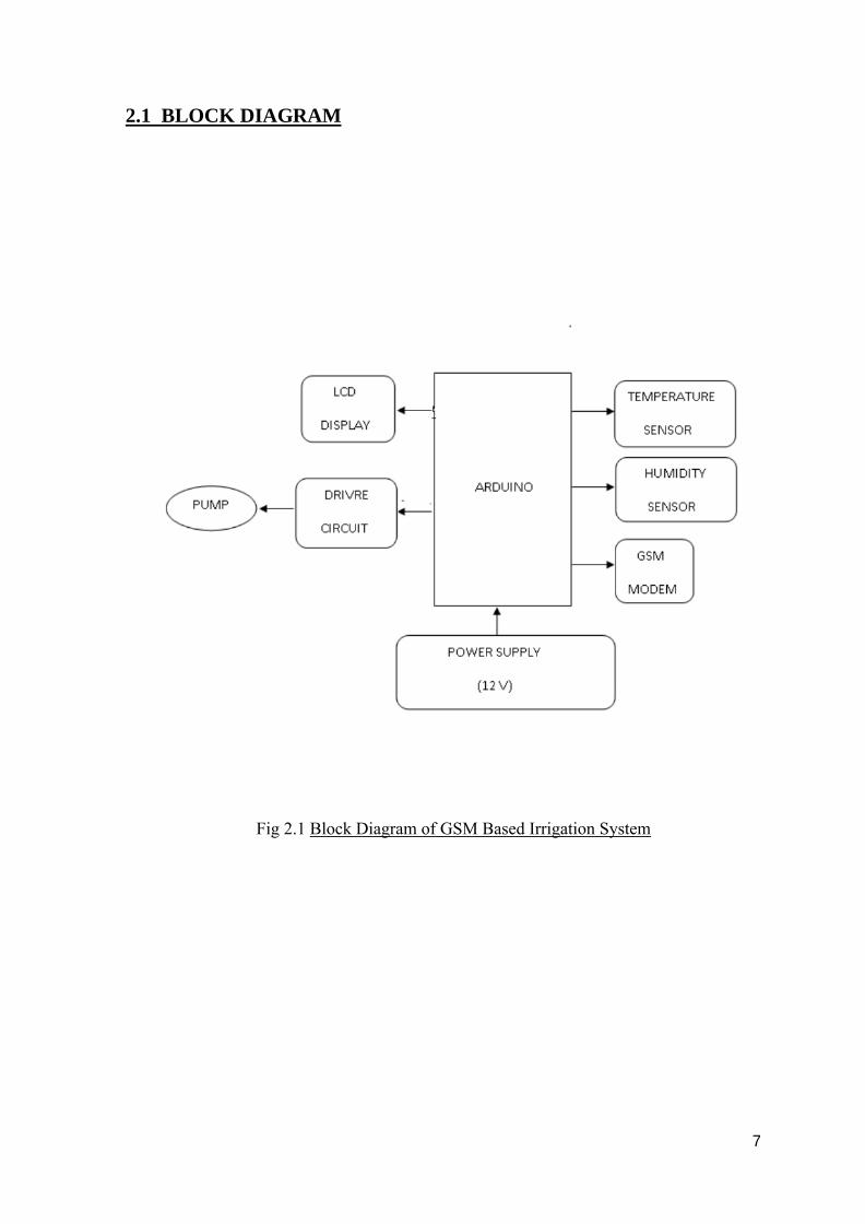
2.1 BLOCK DIAGRAM
Fig 2.1 Block Diagram of GSM Based Irrigation System
8
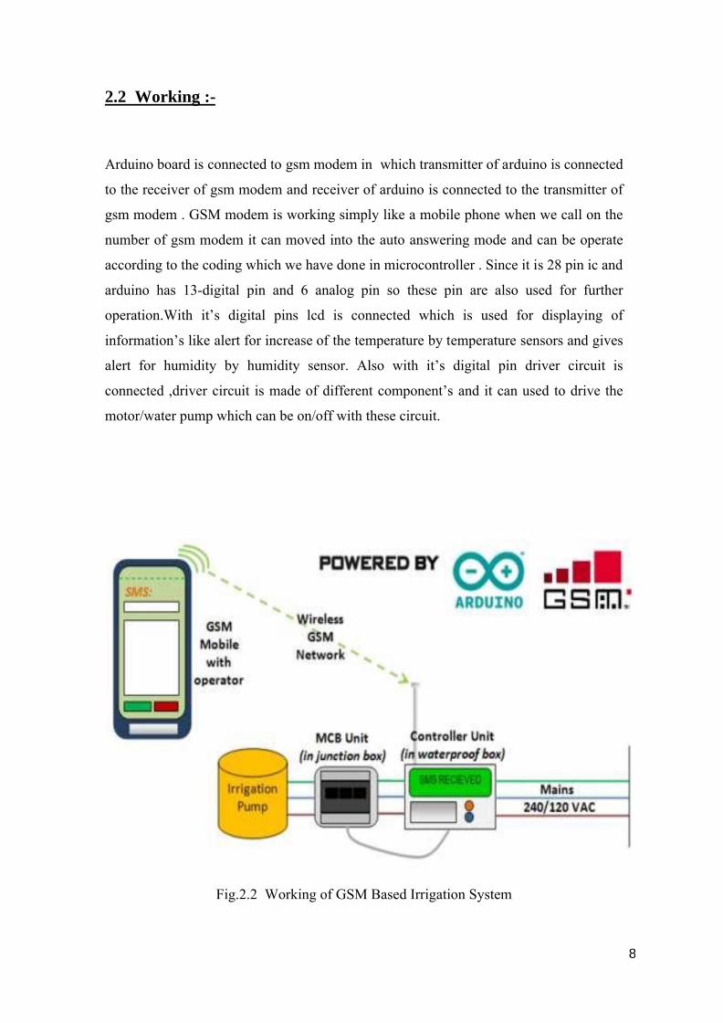
2.2 Working :-
Arduino board is connected to gsm modem in which transmitter of arduino is connected
to the receiver of gsm modem and receiver of arduino is connected to the transmitter of
gsm modem . GSM modem is working simply like a mobile phone when we call on the
number of gsm modem it can moved into the auto answering mode and can be operate
according to the coding which we have done in microcontroller . Since it is 28 pin ic and
arduino has 13-digital pin and 6 analog pin so these pin are also used for further
operation.With it’s digital pins lcd is connected which is used for displaying of
information’s like alert for increase of the temperature by temperature sensors and gives
alert for humidity by humidity sensor. Also with it’s digital pin driver circuit is
connected ,driver circuit is made of different component’s and it can used to drive the
motor/water pump which can be on/off with these circuit.
Fig.2.2 Working of GSM Based Irrigation System
9
CHAPTER -3
CIRCUIT DIAGRAM AND WORKING
10
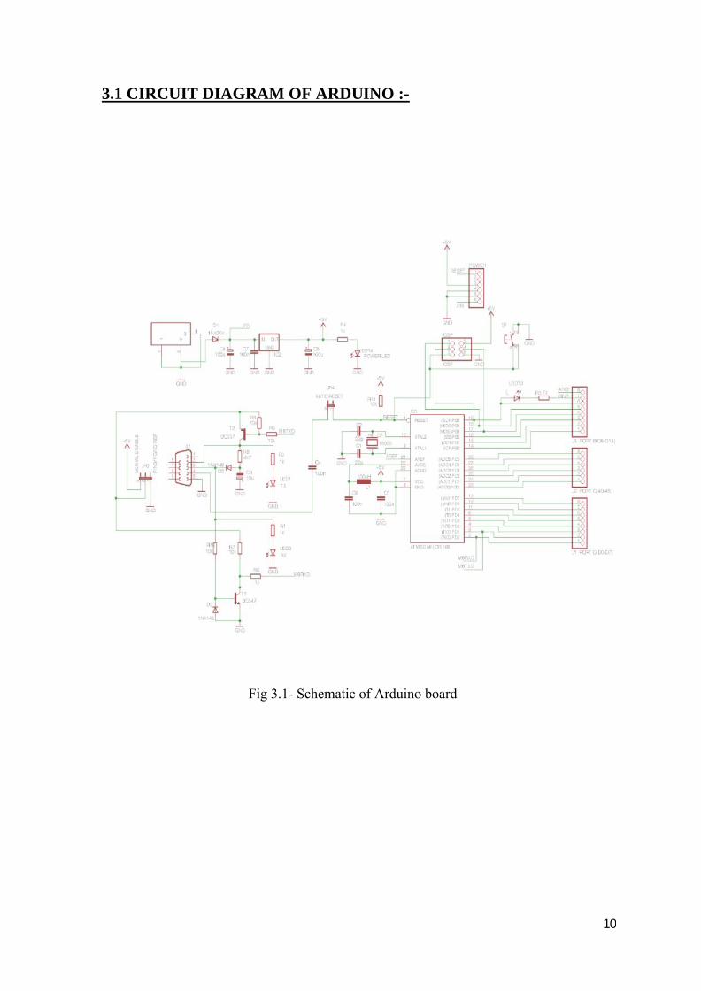
3.1 CIRCUIT DIAGRAM OF ARDUINO :-
Fig 3.1- Schematic of Arduino board
11
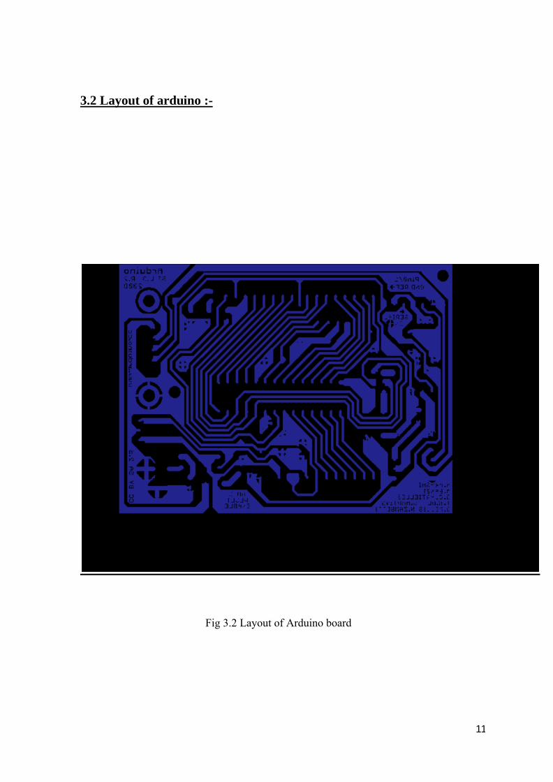
3.2 Layout of arduino :-
Fig 3.2 Layout of Arduino board

12
3.3 Circuit diagram of driver circuit :-
Fig 3.3 Schematic of Relay circuit

13
3.4 Layout of driver circuit :-
Fig 3.4 Layout of Relay circuit
14
3.5 Working of circuit :-
In the GSM BASED IRRIGATION SYSTEM here 28-pin microcontroller is used which is
known as Arduino. Arduino has 13-digital pins and 6-analog pins and it works on 12V d.c. then
we interface arduino with gsm modem here transmitter of arduino is connected with receiver of
gsm modem and receiver of arduino is connected to transmitter of gsm modem and 5v from
arduino is given to gsm modem and sim is inserted in gsm modem which can be used for the
operation of modem. DTMF circuit is connected with modem which can generate a pulse of
binary sequence works according to it.
.LCD i.e. Liquid Crystal Display which is connected to the digital pin of arduino i.e from
12,11,5,4,3,2 which is use in the operation of lcd and it can be use for the displaying of message
or information or for alert.
Here the two sensor ‘s are used which are humidity sensor and temperature sensor. Humidity
sensor is use to show the presence of water in air which is harmful for crops and the another
sensor is temperature which measure the temperature of the atmosphere. These sensors are
connected to the analog pin of arduino which are pin number-4, 5 .According to our coding if
any value is increase between these sensors then it gives alert to us in the form of “alert” tour
number through gsm modem.
Driver circuit is connected to the pin number 9 of the arduino and it is consist of resistor of 10k
which is connected to the npn transistor which is connected to diode and relay of 12V and these
relay is used to drive a water pump.When we give 2 to the dtmf it can generate a pulse sequence
the moves to the and complets a circuit and on the pump and when give 1 it can off the pump.
15
CHAPTER-4
HARDWARE SPECIFICATION
16
4.1 Hardware specification :-
4.1.1 At Transmitter :-
Mobile Phone
4.1.2 At Receiver :-
a. Arduinob. GSM Modemc. Humidity Sensord. Temperature Sensor LM35e. Relay (12v SPDT)f. DTMF 8870 ICg. NPN Transistor (IC 547)h. Silicon Diodei. Submersible pump
17
4.1.1 At Transmitter :-
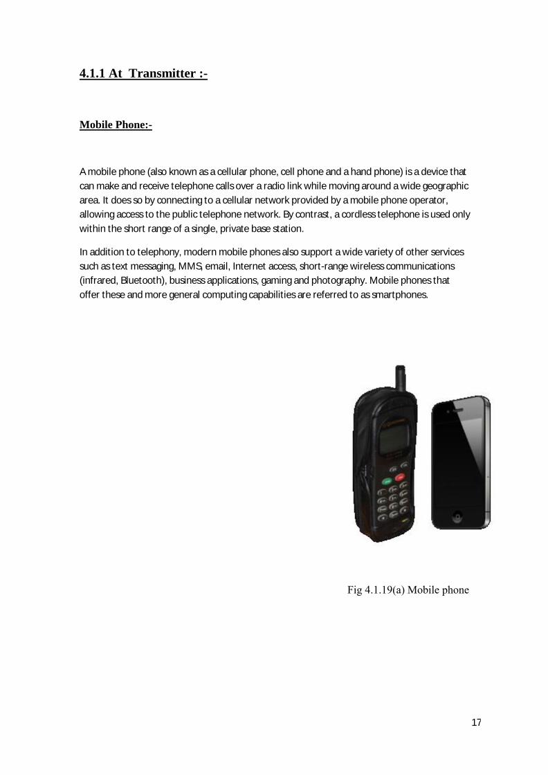
Mobile Phone:-
A mobile phone (also known as a cellular phone, cell phone and a hand phone) is a device that can make and receive telephone calls over a radio link while moving around a wide geographic area. It does so by connecting to a cellular network provided by a mobile phone operator, allowing access to the public telephone network. By contrast, a cordless telephone is used only within the short range of a single, private base station.
In addition to telephony, modern mobile phones also support a wide variety of other services such as text messaging, MMS, email, Internet access, short-range wireless communications (infrared, Bluetooth), business applications, gaming and photography. Mobile phones that offer these and more general computing capabilities are referred to as smartphones.
Fig 4.1.19(a) Mobile phone
18
4.1.2 At Receiver :-
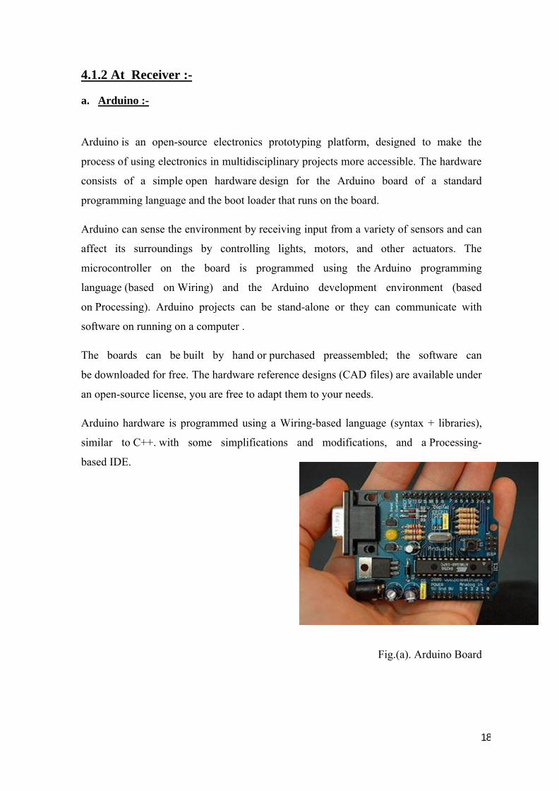
a. Arduino :-
Arduino is an open-source electronics prototyping platform, designed to make the
process of using electronics in multidisciplinary projects more accessible. The hardware
consists of a simple open hardware design for the Arduino board of a standard
programming language and the boot loader that runs on the board.
Arduino can sense the environment by receiving input from a variety of sensors and can
affect its surroundings by controlling lights, motors, and other actuators. The
microcontroller on the board is programmed using the Arduino programming
language (based on Wiring) and the Arduino development environment (based
on Processing). Arduino projects can be stand-alone or they can communicate with
software on running on a computer .
The boards can be built by hand or purchased preassembled; the software can
be downloaded for free. The hardware reference designs (CAD files) are available under
an open-source license, you are free to adapt them to your needs.
Arduino hardware is programmed using a Wiring-based language (syntax + libraries),
similar to C++. with some simplifications and modifications, and a Processing-
based IDE.
Fig.(a). Arduino Board
19
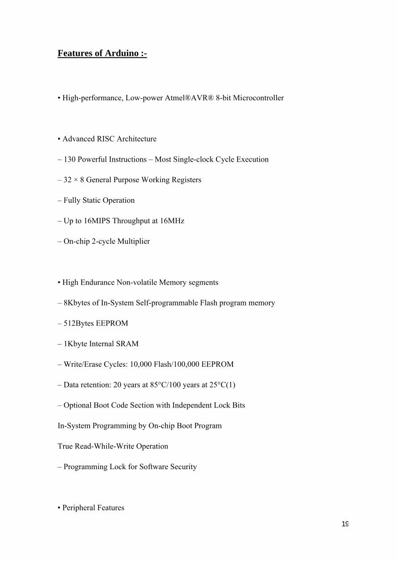
Features of Arduino :-
• High-performance, Low-power Atmel®AVR® 8-bit Microcontroller
• Advanced RISC Architecture
– 130 Powerful Instructions – Most Single-clock Cycle Execution
– 32 × 8 General Purpose Working Registers
– Fully Static Operation
– Up to 16MIPS Throughput at 16MHz
– On-chip 2-cycle Multiplier
• High Endurance Non-volatile Memory segments
– 8Kbytes of In-System Self-programmable Flash program memory
– 512Bytes EEPROM
– 1Kbyte Internal SRAM
– Write/Erase Cycles: 10,000 Flash/100,000 EEPROM
– Data retention: 20 years at 85°C/100 years at 25°C(1)
– Optional Boot Code Section with Independent Lock Bits
In-System Programming by On-chip Boot Program
True Read-While-Write Operation
– Programming Lock for Software Security
• Peripheral Features
20
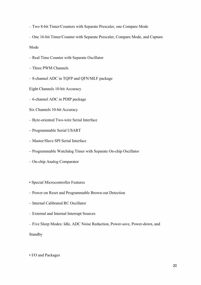
– Two 8-bit Timer/Counters with Separate Prescaler, one Compare Mode
– One 16-bit Timer/Counter with Separate Prescaler, Compare Mode, and Capture
Mode
– Real Time Counter with Separate Oscillator
– Three PWM Channels
– 8-channel ADC in TQFP and QFN/MLF package
Eight Channels 10-bit Accuracy
– 6-channel ADC in PDIP package
Six Channels 10-bit Accuracy
– Byte-oriented Two-wire Serial Interface
– Programmable Serial USART
– Master/Slave SPI Serial Interface
– Programmable Watchdog Timer with Separate On-chip Oscillator
– On-chip Analog Comparator
• Special Microcontroller Features
– Power-on Reset and Programmable Brown-out Detection
– Internal Calibrated RC Oscillator
– External and Internal Interrupt Sources
– Five Sleep Modes: Idle, ADC Noise Reduction, Power-save, Power-down, and
Standby
• I/O and Packages
21
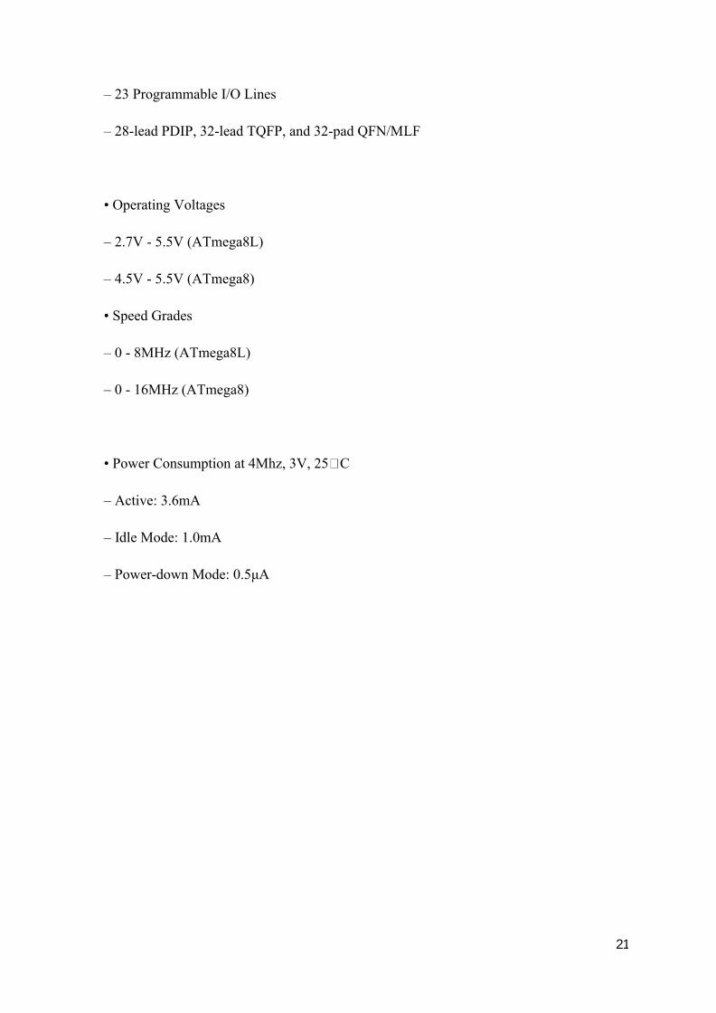
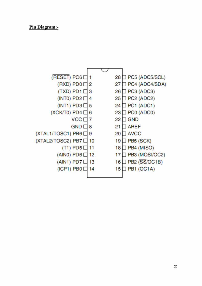
– 23 Programmable I/O Lines
– 28-lead PDIP, 32-lead TQFP, and 32-pad QFN/MLF
• Operating Voltages
– 2.7V - 5.5V (ATmega8L)
– 4.5V - 5.5V (ATmega8)
• Speed Grades
– 0 - 8MHz (ATmega8L)
– 0 - 16MHz (ATmega8)
• Power Consumption at 4Mhz, 3V, 25 C
– Active: 3.6mA
– Idle Mode: 1.0mA
– Power-down Mode: 0.5μA
22
Pin Diagram:-
23
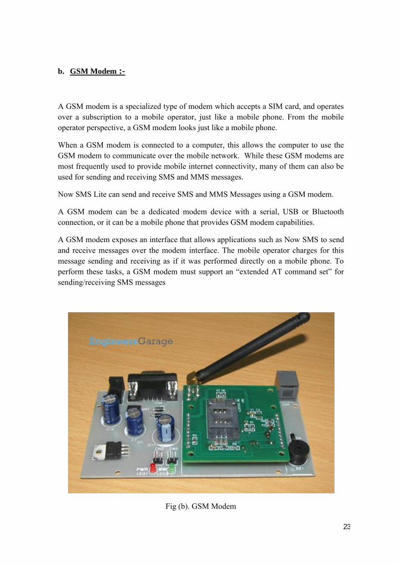
b. GSM Modem :-
A GSM modem is a specialized type of modem which accepts a SIM card, and operates over a subscription to a mobile operator, just like a mobile phone. From the mobile operator perspective, a GSM modem looks just like a mobile phone.
When a GSM modem is connected to a computer, this allows the computer to use the GSM modem to communicate over the mobile network. While these GSM modems are most frequently used to provide mobile internet connectivity, many of them can also be used for sending and receiving SMS and MMS messages.
Now SMS Lite can send and receive SMS and MMS Messages using a GSM modem.
A GSM modem can be a dedicated modem device with a serial, USB or Bluetooth connection, or it can be a mobile phone that provides GSM modem capabilities.
A GSM modem exposes an interface that allows applications such as Now SMS to send and receive messages over the modem interface. The mobile operator charges for this message sending and receiving as if it was performed directly on a mobile phone. To perform these tasks, a GSM modem must support an “extended AT command set” for sending/receiving SMS messages
Fig (b). GSM Modem
24
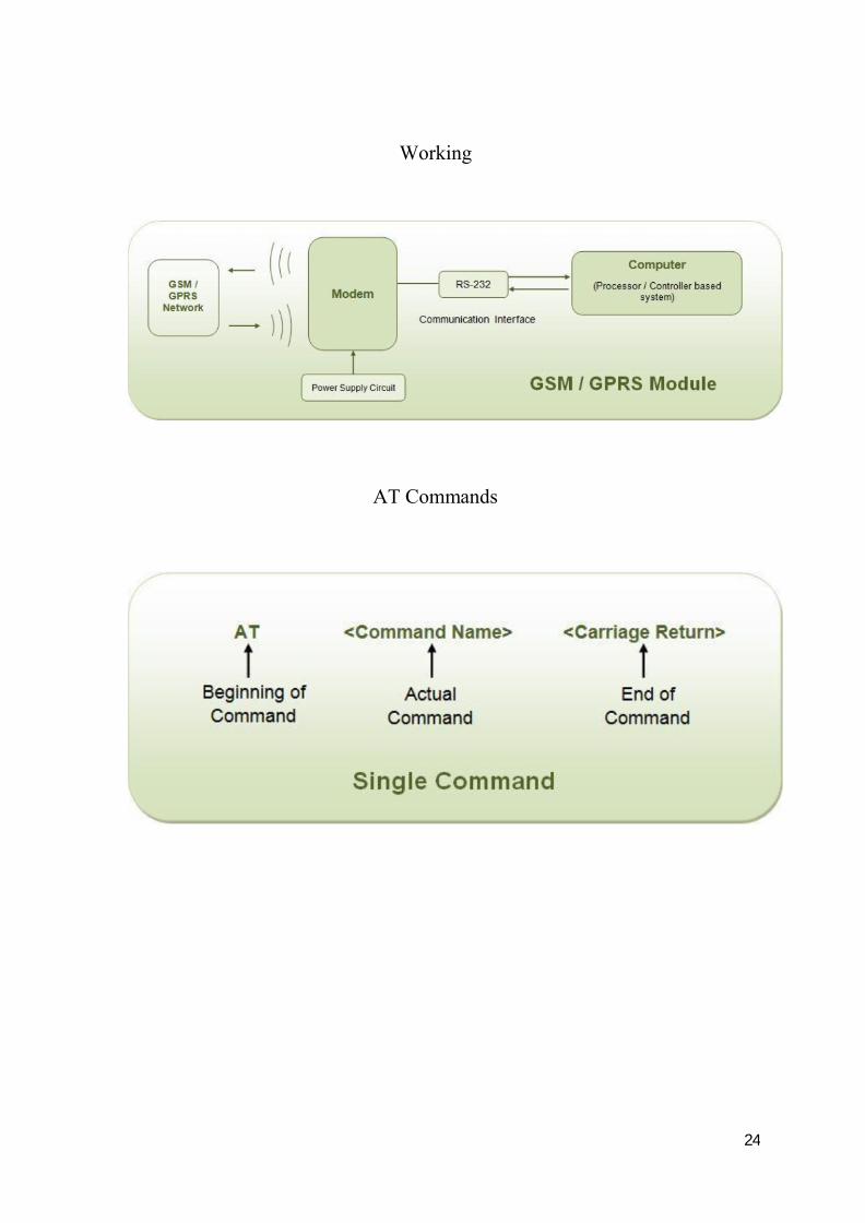
Working
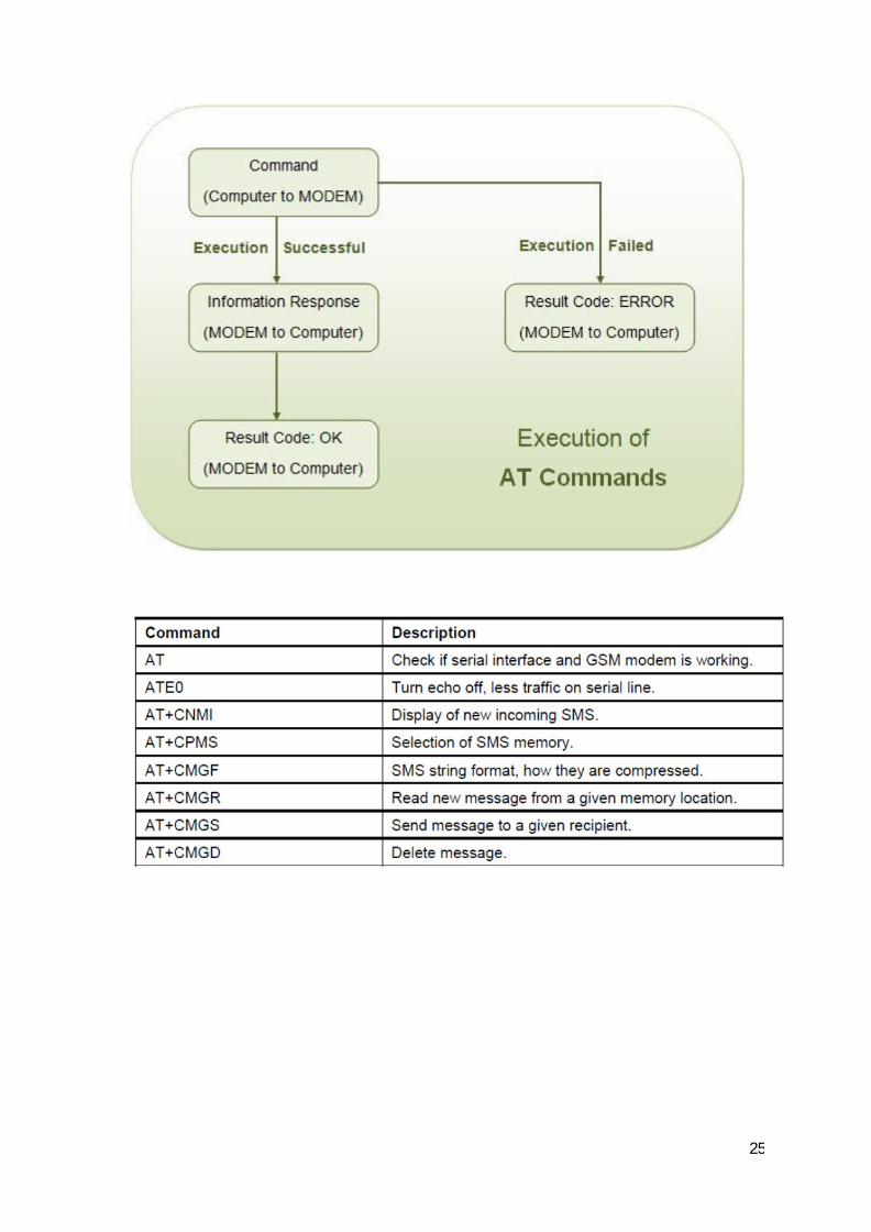
AT Commands
25

26
c. Humidity Sensor :-
Humidity is the presence of water in air. The amount of water vapor in air can affect
human comfort as well as many manufacturing processes in industries. The presence of
water vapor also influences various physical, chemical, and biological processes.
Humidity measurement in industries is critical because it may affect the business cost of
the product and the health and safety of the personnel. Hence, humidity sensing is very
important, especially in the control systems for industrial processes and human comfort.
Controlling or monitoring humidity is of paramount importance in many industrial &
domestic applications. In semiconductor industry, humidity or moisture levels needs to
be properly controlled & monitored during wafer processing. In medical applications,
humidity control is required for respiratory equipments, sterilizers, incubators,
pharmaceutical processing, and biological products. Humidity control is also necessary
in chemical gas purification, dryers, ovens, film desiccation, paper and textile
production, and food processing. In agriculture, measurement of humidity is important
for plantation protection (dew prevention), soil moisture monitoring, etc. For domestic
applications, humidity control is required for living environment in buildings, cooking
control for microwave ovens, etc. In all such applications and many others, humidity
sensors are employed to provide an indication of the moisture levels in the environment.
RELEVANT MOISTURE TERMS:-To mention moisture levels, variety of
terminologies are used. The study of water vapour concentration in air as a function of
temperature and pressure falls under the area of psychometrics. Psychometrics deals
with the thermodynamic properties of moist gases while the term “humidity’ simply
refers to the presence of water vapour in air or other carrier gas. Humidity measurement
determines the amount of water vapor present in a gas that can be a mixture, such as
air,or a pure gas, such as nitrogen or argon.
Fig (c). Humidity Sensor
27
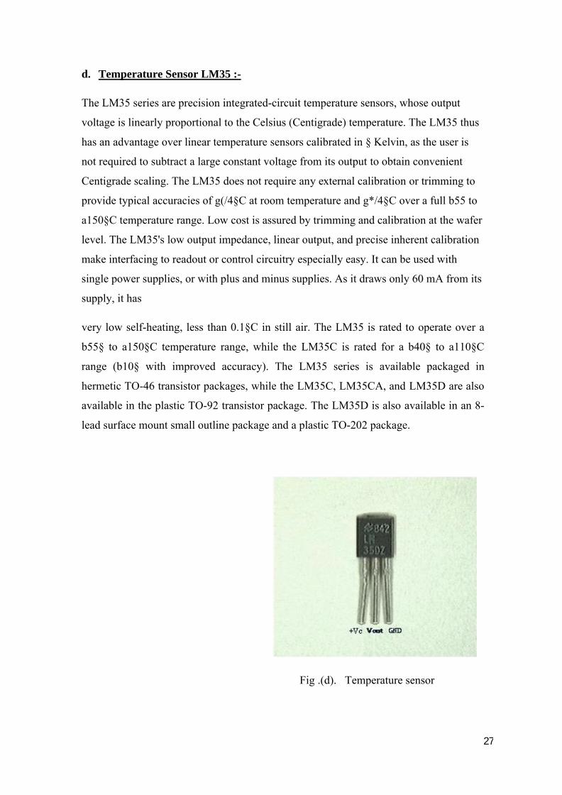
d. Temperature Sensor LM35 :-
The LM35 series are precision integrated-circuit temperature sensors, whose output
voltage is linearly proportional to the Celsius (Centigrade) temperature. The LM35 thus
has an advantage over linear temperature sensors calibrated in § Kelvin, as the user is
not required to subtract a large constant voltage from its output to obtain convenient
Centigrade scaling. The LM35 does not require any external calibration or trimming to
provide typical accuracies of g(/4§C at room temperature and g*/4§C over a full b55 to
a150§C temperature range. Low cost is assured by trimming and calibration at the wafer
level. The LM35's low output impedance, linear output, and precise inherent calibration
make interfacing to readout or control circuitry especially easy. It can be used with
single power supplies, or with plus and minus supplies. As it draws only 60 mA from its
supply, it has
very low self-heating, less than 0.1§C in still air. The LM35 is rated to operate over a
b55§ to a150§C temperature range, while the LM35C is rated for a b40§ to a110§C
range (b10§ with improved accuracy). The LM35 series is available packaged in
hermetic TO-46 transistor packages, while the LM35C, LM35CA, and LM35D are also
available in the plastic TO-92 transistor package. The LM35D is also available in an 8-
lead surface mount small outline package and a plastic TO-202 package.
Fig .(d). Temperature sensor
28
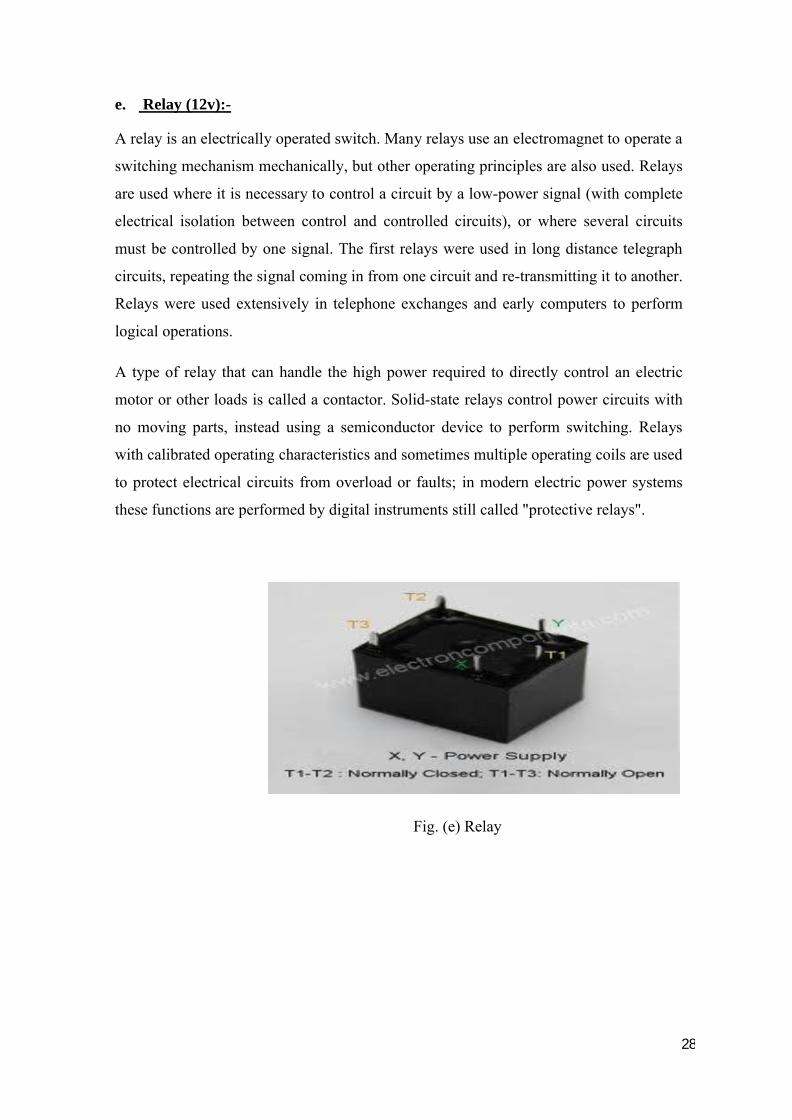
e. Relay (12v):-
A relay is an electrically operated switch. Many relays use an electromagnet to operate a
switching mechanism mechanically, but other operating principles are also used. Relays
are used where it is necessary to control a circuit by a low-power signal (with complete
electrical isolation between control and controlled circuits), or where several circuits
must be controlled by one signal. The first relays were used in long distance telegraph
circuits, repeating the signal coming in from one circuit and re-transmitting it to another.
Relays were used extensively in telephone exchanges and early computers to perform
logical operations.
A type of relay that can handle the high power required to directly control an electric
motor or other loads is called a contactor. Solid-state relays control power circuits with
no moving parts, instead using a semiconductor device to perform switching. Relays
with calibrated operating characteristics and sometimes multiple operating coils are used
to protect electrical circuits from overload or faults; in modern electric power systems
these functions are performed by digital instruments still called "protective relays".
Fig. (e) Relay
29
Basic Design and Operation :-
When an electric current is passed through the coil it generates a magnetic field that
activates the armature, and the consequent movement of the movable contact(s) either
makes or breaks (depending upon construction) a connection with a fixed contact. If the
set of contacts was closed when the relay was de-energized, then the movement opens
the contacts and breaks the connection, and vice versa if the contacts were open. When
the current to the coil is switched off, the armature is returned by a force, approximately
half as strong as the magnetic force, to its relaxed position. Usually this force is
provided by a spring, but gravity is also used commonly in industrial motor starters.
Most relays are manufactured to operate quickly. In a low-voltage application this
reduces noise; in a high voltage or current application it reduces arcing.
When the coil is energized with direct current, a diode is often placed across the coil to
dissipate the energy from the collapsing magnetic field at deactivation, which would
otherwise generate a voltage spike dangerous to semiconductor circuit components.
Some automotive relays include a diode inside the relay case. Alternatively, a contact
protection network consisting of a capacitor and resistor in series (snubber circuit) may
absorb the surge. If the coil is designed to be energized with alternating current (AC), a
small copper "shading ring" can be crimped to the end of the solenoid, creating a small
out-of-phase current which increases the minimum pull on the armature during the AC
cycle.
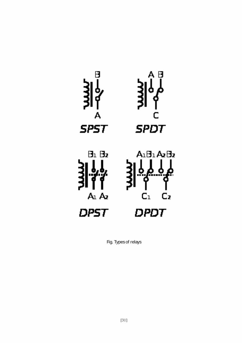
TYPES OF RELAY :-
SPST – Single Pole Single Throw. These have two terminals which can be connected or
disconnected. Including two for the coil, such a relay has four terminals in total. It is
ambiguous whether the pole is normally open or normally closed.
SPDT – Single Pole Double Throw. A common terminal connects to either of two
others. Including two for the coil, such a relay has five terminals in total.
30
DPST – Double Pole Single Throw. These have two pairs of terminals. Equivalent to
two SPST switches or relays actuated by a single coil. Including two for the coil, such a
relay has six terminals in total. The poles may be Form A or Form B (or one of each).
DPDT – Double Pole Double Throw. These have two rows of change-over terminals.
Equivalent to two SPDT switches or relays actuated by a single coil. Such a relay has
eight terminals, including the coil.
[31]
Fig. Types of relays
[32]
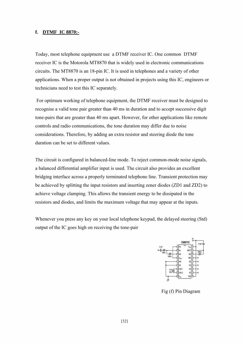
f. DTMF IC 8870:-
Today, most telephone equipment use a DTMF receiver IC. One common DTMF
receiver IC is the Motorola MT8870 that is widely used in electronic communications
circuits. The MT8870 is an 18-pin IC. It is used in telephones and a variety of other
applications. When a proper output is not obtained in projects using this IC, engineers or
technicians need to test this IC separately.
For optimum working of telephone equipment, the DTMF receiver must be designed to
recognise a valid tone pair greater than 40 ms in duration and to accept successive digit
tone-pairs that are greater than 40 ms apart. However, for other applications like remote
controls and radio communications, the tone duration may differ due to noise
considerations. Therefore, by adding an extra resistor and steering diode the tone
duration can be set to different values.
The circuit is configured in balanced-line mode. To reject common-mode noise signals,
a balanced differential amplifier input is used. The circuit also provides an excellent
bridging interface across a properly terminated telephone line. Transient protection may
be achieved by splitting the input resistors and inserting zener diodes (ZD1 and ZD2) to
achieve voltage clamping. This allows the transient energy to be dissipated in the
resistors and diodes, and limits the maximum voltage that may appear at the inputs.
Whenever you press any key on your local telephone keypad, the delayed steering (Std)
output of the IC goes high on receiving the tone-pair
Fig (f) Pin Diagram
[33]
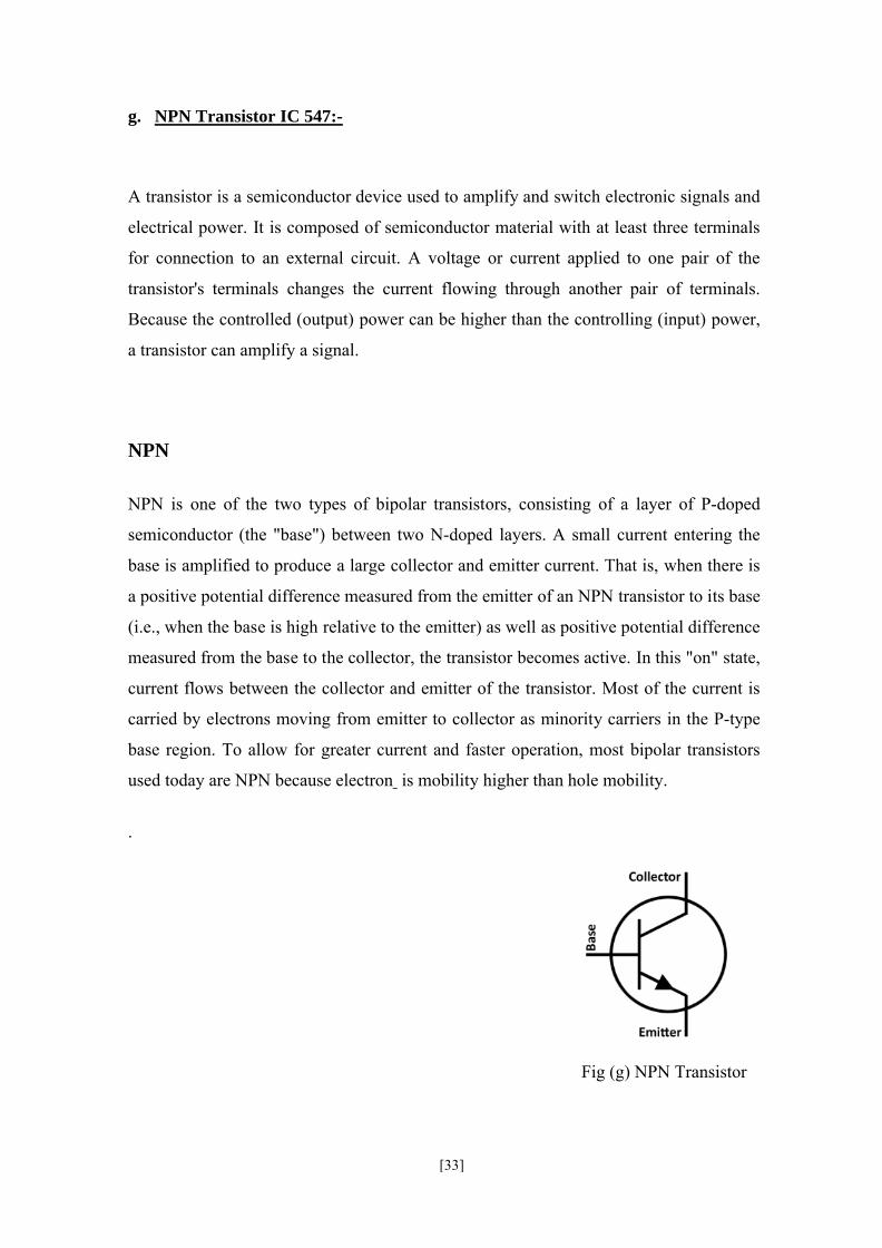
g. NPN Transistor IC 547:-
A transistor is a semiconductor device used to amplify and switch electronic signals and
electrical power. It is composed of semiconductor material with at least three terminals
for connection to an external circuit. A voltage or current applied to one pair of the
transistor's terminals changes the current flowing through another pair of terminals.
Because the controlled (output) power can be higher than the controlling (input) power,
a transistor can amplify a signal.
NPN
NPN is one of the two types of bipolar transistors, consisting of a layer of P-doped
semiconductor (the "base") between two N-doped layers. A small current entering the
base is amplified to produce a large collector and emitter current. That is, when there is
a positive potential difference measured from the emitter of an NPN transistor to its base
(i.e., when the base is high relative to the emitter) as well as positive potential difference
measured from the base to the collector, the transistor becomes active. In this "on" state,
current flows between the collector and emitter of the transistor. Most of the current is
carried by electrons moving from emitter to collector as minority carriers in the P-type
base region. To allow for greater current and faster operation, most bipolar transistors
used today are NPN because electron is mobility higher than hole mobility.
.
Fig (g) NPN Transistor
[34]
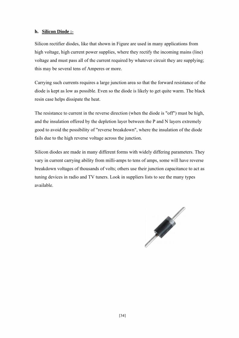
h. Silicon Diode :-
Silicon rectifier diodes, like that shown in Figure are used in many applications from
high voltage, high current power supplies, where they rectify the incoming mains (line)
voltage and must pass all of the current required by whatever circuit they are supplying;
this may be several tens of Amperes or more.
Carrying such currents requires a large junction area so that the forward resistance of the
diode is kept as low as possible. Even so the diode is likely to get quite warm. The black
resin case helps dissipate the heat.
The resistance to current in the reverse direction (when the diode is "off") must be high,
and the insulation offered by the depletion layer between the P and N layers extremely
good to avoid the possibility of "reverse breakdown", where the insulation of the diode
fails due to the high reverse voltage across the junction.
Silicon diodes are made in many different forms with widely differing parameters. They
vary in current carrying ability from milli-amps to tens of amps, some will have reverse
breakdown voltages of thousands of volts; others use their junction capacitance to act as
tuning devices in radio and TV tuners. Look in suppliers lists to see the many types
available.
[35]
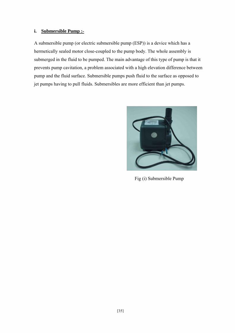
i. Submersible Pump :-
A submersible pump (or electric submersible pump (ESP)) is a device which has a
hermetically sealed motor close-coupled to the pump body. The whole assembly is
submerged in the fluid to be pumped. The main advantage of this type of pump is that it
prevents pump cavitation, a problem associated with a high elevation difference between
pump and the fluid surface. Submersible pumps push fluid to the surface as opposed to
jet pumps having to pull fluids. Submersibles are more efficient than jet pumps.
Fig (i) Submersible Pump
[36]
Software Specification :-
Aurdino software IDE
The aurduino IDE is a cross plateform application written in java which is derived from the IDE
made for the processing programming language and the wiring project. It is designed to
introduce programming to artists and other newcomers unfamiliar with software development.
It includes a code editor with feature such as syntax highlighting , brace matching, and
automatic indentation, and is also capable of compiling and uploading programs to the board
with the single clik. There is typically no need to edit make files or run programs on the
command line.
The arduino development environment contains a text editor for writing code, a message area,
a text console, a toolbar with buttons for comman functions, and series of menus. It connects
to the arduino hardware to upload programs and communicate with them.
∑ Software written using arduino are called sketches. These sketches are written in the
text editor. It has features for cutting/pasting and for searching/replacing text. The
message area gives feedback while saving and exporting and also displays
errors. The console displays text output by the arduino environment including
complete error messages and other information. Arduino IDE comes with a C/C+
+library called “wiring”, which makes many common input/output operations much
easier. Arduino pragrames are written in C/C++, although users only need to define
two functions in order to make a runnable program.

[37]
Description of eagle software :-
Introduction:
This eagle (easily applicable graphical layout editor) PCB design software is used to design an
electronic schematic and layout a printed circuit board (PCB). Eagle is a PCB design software
package consisting of a schematics editor, a PCB editor and an auto router module. The
software comes with an extensive library of components, but a library editor is also available to
design new parts or or modify existing ones. Eagle is made by cadsoft and is available in three
versions. The light versions is limited to one sheet of schematic and half euro card formate, but
can be used under the terms of the freeware licence for non- commercial use. This software
can be download from cadsoft’s homepage, for windows or linux. We ware investigating the
possibilities of getting one or more licence for the professional version ,which does not have
these limitations.
The formate of PCB layout is carried out in following steps:
Step 1- Drawing the schematic
Step 2- Printing the schematic
Step 3- PCB layout
∑ Placing components
∑ Routing
∑ Printing the PCB

[38]
CHAPTER -4
CODING
[39]
Coding :-
#include <LiquidCrystal.h>
LiquidCrystal lcd(12,11,5,4,3,2);
int sens1=A5;
int sens2=A4;
int dtmf1=7;
int dtmf2=6;
int relay=8;
int a,b,c;
int count=0;
char phoneNumber[]="+919753475722";
void setup()
{
Serial.begin(9600);
lcd.begin(16,2);
[40]
pinMode(relay,OUTPUT);
pinMode(dtmf1,INPUT);
pinMode(dtmf2,INPUT);
digitalWrite(dtmf1,HIGH);
digitalWrite(dtmf2,HIGH);
lcd.print("GSM IRRIGATION");
lcd.setCursor(0,1);
lcd.print("SYSTEM");
delay(2000);
lcd.clear();
lcd.print("SDBCE, INDORE");
delay(3000);
lcd.clear();
lcd.print("Presented By:");
delay(2000);
lcd.clear();
lcd.print("Pravar Upadhyay");
delay(2000);
lcd.clear();
lcd.print("Vipul Joshi");
delay(2000);
lcd.clear();
lcd.print("Shiv Kumar Mourya");
[41]
delay(2000);
lcd.clear();
lcd.print("Vinod Gothi");
delay(2000);
lcd.clear();
lcd.print("gsm starting");
delay(10000);
lcd.clear();
Serial.print("ATSo=2");
Serial.print(13,BYTE);
}
void loop()
{
a=analogRead(sens1);
c=a/2;
b=analogRead(sens2);
if(c>50 || b>500)
{
delay(500);
[42]
lcd.print("sending");
Serial.println("AT+CMGF=1");
Serial.print("AT+CMGS=");
Serial.print(34,BYTE);
Serial.print(phoneNumber);
Serial.println(34,BYTE);
delay(500);
Serial.print("Alert!!!");
Serial.print(26,BYTE);
delay(5000);
lcd.print("sended");
lcd.clear();
}
if (digitalRead(dtmf1) == HIGH && digitalRead(dtmf2) == LOW) //one
{
digitalWrite(relay,LOW);
lcd.setCursor(0,1);
lcd.print("OFF");
delay(50);
[43]
}
else if (digitalRead(dtmf1) == LOW && digitalRead(dtmf2) == HIGH) //two
{
digitalWrite(relay,HIGH);
lcd.setCursor(0,1);
lcd.print("ON");
delay(50);
}
}

[44]
CHAPTER-5
CONCLUSION
[45]
CONCLUSION :-
There is an urgent need for a system that makes the agricultural process easier and
burden free from the farmer’s side. With the recent advancement of technology it has
become necessary to increase the annual crop production output of our country India, an
entirely agro centric economy. The ability to conserve the natural resources as well as
giving a splendid boost to the production of the crops is one of the main aims of
incorporating such technology into the agricultural domain of the country. To save
farmer’s effort, water and time has been the most important consideration. Hence
systems need to be designed to provide this ability efficiently using wireless sensor
networking, sprinkler irrigation, GSM, SMS technology,
These systems were all remotely controlled systems which proposed a low cost
information exchange via SMS and GSM network. The soil moisture, humidity and
various other environmental factors influencing growth of crops are periodically sensed
using high quality accurate sensor and those values are passed on to the
processor/controller to calculate required amount of water and fertilizers and various
other inputs during irrigation and accordingly supplied to the farm. The functionality of
GSM increases the efficiency of the automated irrigation system by giving it a more user
friendly interface using SMS (Short Message Service) coupled with missed called
services.
The result of the survey conducted has lead to a very positive approach on the impact of
GSM technology in farm irrigation methods and techniques. The approaches studied had
various pros and cons in the time required for operations or complexity or feasibility and
user interactions. With technology advancing everyday new techniques have been
implemented for further minimizing the irrigation process like using prebuilt mobile
phone or standalone application software for conduction the irrigation process.

[46]
CHAPTER-6
ADVANTAGES & DISADVANTAGE
[47]
Advantages:-
• Increase crop yields and quality, while saving on operational costs and labor.
• Automatically and accurately irrigate and fertilize (irrigate + fertilize =
fertigate) crops by remote control - with exactly the right quantity, at exactly the
right time, activating specific valves.
• Reduce water consumption; optimize use of fertilizers, and minimize energy
costs.
• Manage the irrigation process from practically anywhere - whether from the
office, from home or on the road.
• Immediately detect any system irregularities and leaks online, and receive real
time reports (even to mobile phones by SMS) while automated response is taking
place.
Disadvantages:-
ó Networks failure : - If the network is fail then the device is not work properly.
ó Effects on human health.
[48]
CHAPTER -7
FUTURE SCOPE
[49]
Future scope:-
This project has enormous potential and may be used in various other ways, due to its
cheap and cost efficient design.
1. Use it as a home automation controller, by adding a few more 240 volt relays.
2. Remotely perform jobs.
3. Use a float switch in a tank, so that the system automatically shuts the pump down,
once the reservoir is full.
4. Use it in conjunction with a solar panel, so that the entire system is eco-friendly.

[50]
CHAPTER-8
DATA SHEETS