Embed Size (px)
Citation preview
For the most current information, visit the Roadranger web site at www.roadranger.com
Single Reduction & Single Reduction w/Wheel Differential LockDS/RS344DS/RS404(P)DS/RS405(P)DS/RS454(P)
DD/RD404DD/RD405DD/RD454
DA/RA344DA/RA404(P)DA/RA405(P)DDT41(P)
DSP/RSP40DSP/RSP41DSH/RSH40DSH/RSH44
DDH/RDH40DDH/RDH44DST40(P)DST41(P)
Dana Spicer® ® Tandem Drive Axles
Service Manual AXSM-0046 January 2001

120FE01 TBC5499
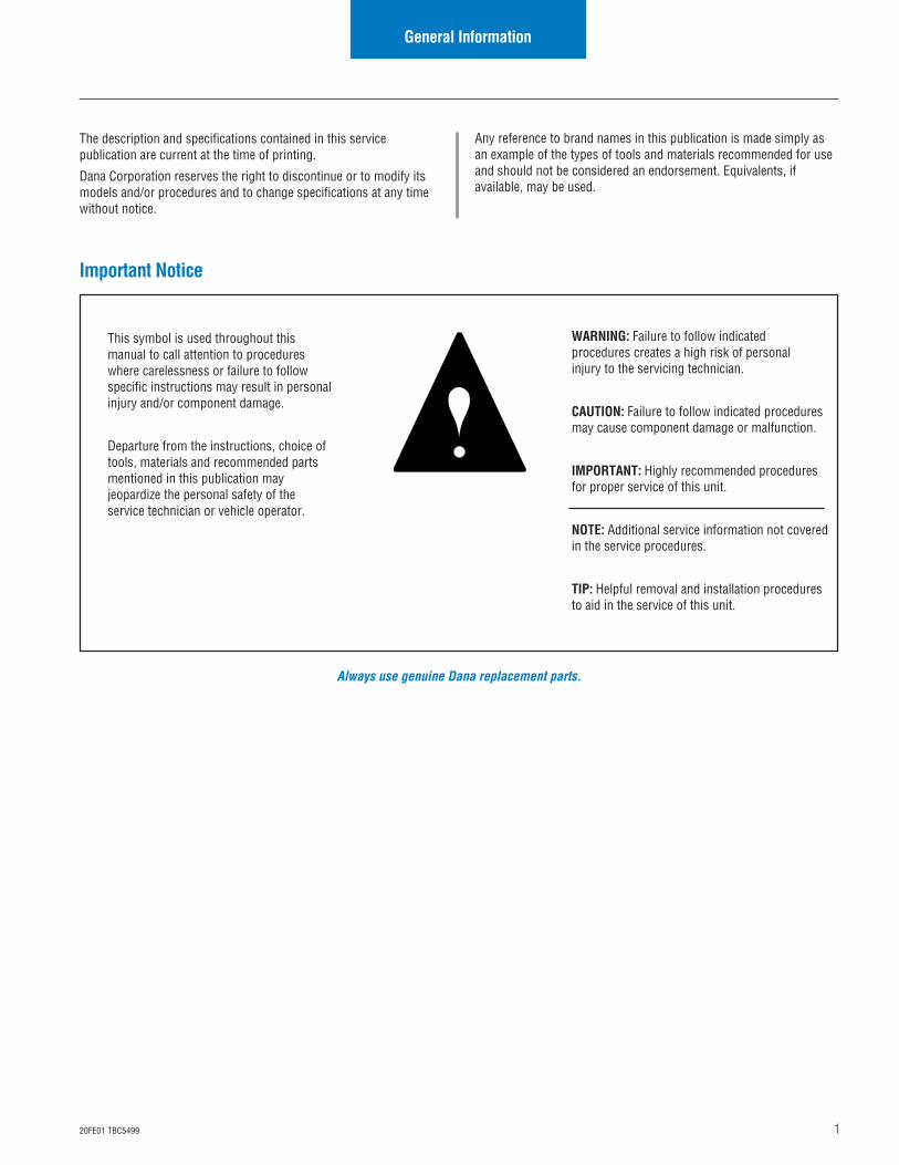
This symbol is used throughout thismanual to call attention to procedureswhere carelessness or failure to followspecific instructions may result in personalinjury and/or component damage.
Departure from the instructions, choice oftools, materials and recommended partsmentioned in this publication mayjeopardize the personal safety of theservice technician or vehicle operator.
WARNING: Failure to follow indicatedprocedures creates a high risk of personalinjury to the servicing technician.
CAUTION: Failure to follow indicated proceduresmay cause component damage or malfunction.
IMPORTANT: Highly recommended proceduresfor proper service of this unit.
NOTE: Additional service information not coveredin the service procedures.
TIP: Helpful removal and installation proceduresto aid in the service of this unit.
Any reference to brand names in this publication is made simply asan example of the types of tools and materials recommended for useand should not be considered an endorsement. Equivalents, ifavailable, may be used.
General Information
The description and specifications contained in this servicepublication are current at the time of printing.
Dana Corporation reserves the right to discontinue or to modify itsmodels and/or procedures and to change specifications at any timewithout notice.
Always use genuine Dana replacement parts.
Important Notice
2 20FE01 TBC5499
General Information
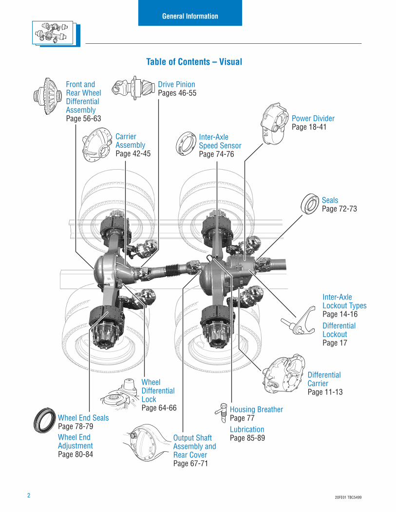
Table of Contents – Visual
Differential CarrierPage 11-13
Power DividerPage 18-41
Front andRear Wheel Differential AssemblyPage 56-63
Output Shaft Assembly and Rear CoverPage 67-71
Housing BreatherPage 77
Differential LockoutPage 17
Inter-Axle Lockout TypesPage 14-16
Drive PinionPages 46-55
Wheel End SealsPage 78-79Wheel EndAdjustmentPage 80-84
Wheel Differential LockPage 64-66
Carrier AssemblyPage 42-45
Inter-Axle Speed SensorPage 74-76
SealsPage 72-73
LubricationPage 85-89
320FE01 TBC5499
General Information
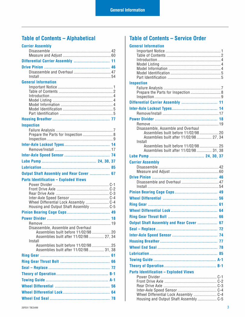
Table of Contents – AlphabeticalCarrier Assembly
Disassemble ............................................................ 42Measure and Adjust ................................................ 60
Differential Carrier Assembly ........................... 11Drive Pinion ................................................. 46
Disassemble and Overhaul ..................................... 47Install ....................................................................... 54
General InformationImportant Notice ....................................................... 1Table of Contents ...................................................... 2Introduction ............................................................... 4Model Listing ............................................................ 4Model Information .................................................... 4Model Identification .................................................. 5Part Identification ..................................................... 5
Housing Breather ........................................... 77Inspection
Failure Analysis ......................................................... 7Prepare the Parts for Inspection .............................. 8Inspection .................................................................. 9
Inter-Axle Lockout Types.................................. 14Remove/Install ........................................................ 17
Inter-Axle Speed Sensor .................................. 74Lube Pump ......................................... 24, 30, 37Lubrication ................................................... 85Output Shaft Assembly and Rear Cover ............... 67Parts Identification – Exploded Views
Power Divider ........................................................ C-1Front Drive Axle .................................................... C-2Rear Drive Axle ..................................................... C-3Inter-Axle Speed Sensor ....................................... C-4Wheel Differential Lock Assembly ....................... C-4Housing and Output Shaft Assembly ................... C-5
Pinion Bearing Cage Cups ................................ 49Power Divider ............................................... 18
Remove.................................................................... 19Disassemble, Assemble and Overhaul
Assemblies built before 11/02/98 ................... 20Assemblies built after 11/02/98 ............... 27, 34
InstallAssemblies built before 11/02/98 ................... 25Assemblies built after 11/02/98 ............... 31, 38
Ring Gear .................................................... 61Ring Gear Thrust Bolt ..................................... 66Seal – Replace .............................................. 72Theory of Operation ....................................... B-1Towing Guide ............................................... A-1Wheel Differential ......................................... 56Wheel Differential Lock ................................... 64Wheel End Seal ............................................. 78
Table of Contents – Service OrderGeneral Information
Important Notice ....................................................... 1Table of Contents ...................................................... 2Introduction ............................................................... 4Model Listing ............................................................ 4Model Information .................................................... 4Model Identification .................................................. 5Part Identification ..................................................... 5
InspectionFailure Analysis ......................................................... 7Prepare the Parts for Inspection .............................. 8Inspection .................................................................. 9
Differential Carrier Assembly ........................... 11Inter-Axle Lockout Types .................................. 14
Remove/Install ........................................................ 17Power Divider ............................................... 18
Remove .................................................................... 19Disassemble, Assemble and Overhaul
Assemblies built before 11/02/98 ................... 20Assemblies built after 11/02/98 ............... 27, 34
InstallAssemblies built before 11/02/98 ................... 25Assemblies built after 11/02/98 ............... 31, 38
Lube Pump ......................................... 24, 30, 37Carrier Assembly
Disassemble ............................................................ 42Measure and Adjust ................................................ 60
Drive Pinion ................................................. 46Disassemble and Overhaul ..................................... 47Install ....................................................................... 54
Pinion Bearing Cage Cups ................................ 49Wheel Differential ......................................... 56Ring Gear .................................................... 61Wheel Differential Lock ................................... 64Ring Gear Thrust Bolt ..................................... 66Output Shaft Assembly and Rear Cover ............... 67Seal – Replace .............................................. 72Inter-Axle Speed Sensor .................................. 74Housing Breather ........................................... 77Wheel End Seal ............................................. 78Lubrication ................................................... 85Towing Guide ............................................... A-1Theory of Operation ....................................... B-1Parts Identification – Exploded Views
Power Divider ........................................................ C-1Front Drive Axle .................................................... C-2Rear Drive Axle ..................................................... C-3Inter-Axle Speed Sensor ....................................... C-4Wheel Differential Lock Assembly ....................... C-4Housing and Output Shaft Assembly ................... C-5
4 20FE01 TBC5499
General Information
Introduction
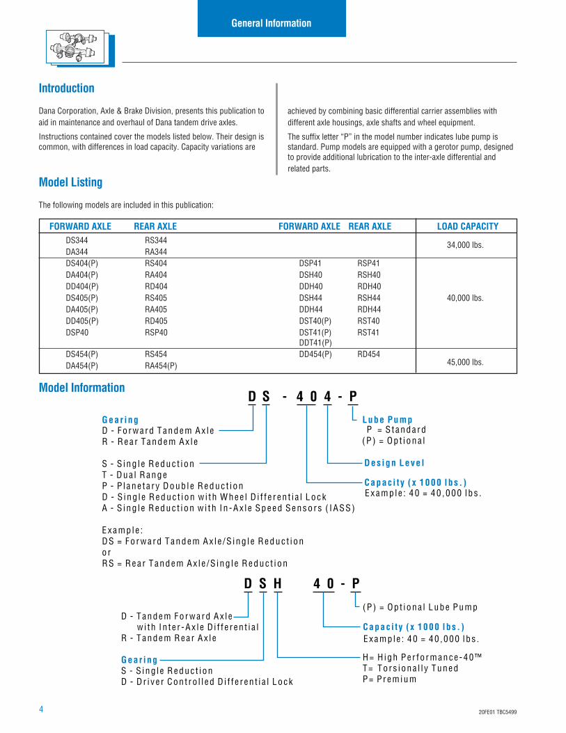
Dana Corporation, Axle & Brake Division, presents this publication toaid in maintenance and overhaul of Dana tandem drive axles.
Instructions contained cover the models listed below. Their design iscommon, with differences in load capacity. Capacity variations are
Gear ing
Capac i t y ( x 1000 l bs . )
Des ign Leve l
Lube PumpD - F o r w a r d T a n d e m A x l eR - R e a r T a n d e m A x l e
S - S i n g l e R e d u c t i o nT - D u a l R a n g eP - P l a n e t a r y D o u b l e R e d u c t i o nD - S i n g l e R e d u c t i o n w i t h W h e e l D i f f e r e n t i a l L o c kA - S i n g l e R e d u c t i o n w i t h I n - A x l e S p e e d S e n s o r s ( I A S S )
E x a m p l e :D S = F o r w a r d T a n d e m A x l e / S i n g l e R e d u c t i o no rR S = R e a r T a n d e m A x l e / S i n g l e R e d u c t i o n
E x a m p l e : 4 0 = 4 0 , 0 0 0 l b s .
P = S t a n d a r d( P ) = O p t i o n a l
D - Tandem Fo r w a r d Ax l e w i t h I n t e r - Ax l e D i f f e r en t i a lR - Tandem R ea r Ax l e
G ear ingS - S i ng l e R educ t i onD - D r i v e r Con t r o l l ed D i f f e r en t i a l Lock
(P ) = Op t i ona l Lube Pump
H= H igh Pe r fo rmance -40™T= Tors i ona l l y TunedP= P rem ium
C a p a c i t y ( x 1 0 0 0 l b s . )Examp le : 40 = 40 ,000 l bs .
Model Listing
The following models are included in this publication:
achieved by combining basic differential carrier assemblies withdifferent axle housings, axle shafts and wheel equipment.
The suffix letter “P” in the model number indicates lube pump isstandard. Pump models are equipped with a gerotor pump, designedto provide additional lubrication to the inter-axle differential andrelated parts.
FORWARD AXLE REAR AXLE FORWARD AXLE REAR AXLE LOAD CAPACITYDS344 RS344 34,000 lbs.DA344 RA344DS404(P) RS404 DSP41 RSP41DA404(P) RA404 DSH40 RSH40DD404(P) RD404 DDH40 RDH40DS405(P) RS405 DSH44 RSH44 40,000 lbs.DA405(P) RA405 DDH44 RDH44DD405(P) RD405 DST40(P) RST40DSP40 RSP40 DST41(P) RST41
DDT41(P)DS454(P) RS454 DD454(P) RD454
45,000 lbs.DA454(P) RA454(P)
Model Information
520FE01 TBC5499
General Information
Model Identification
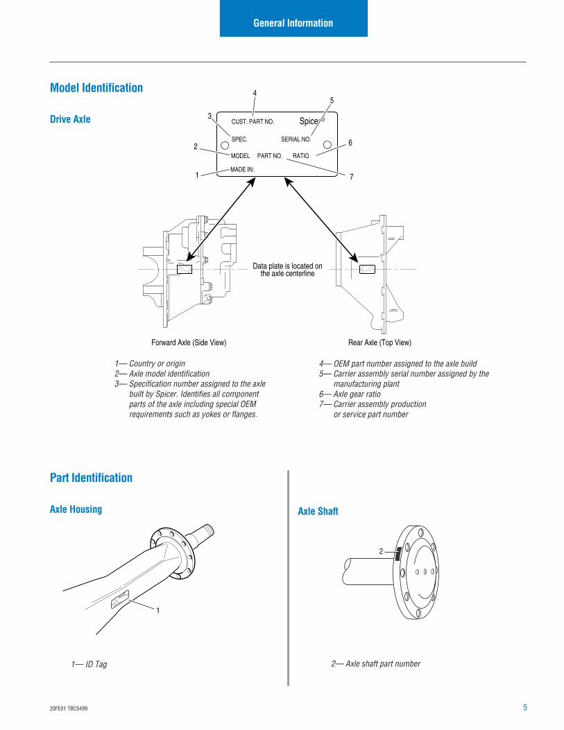
Drive Axle
Axle Shaft
1— Country or origin2— Axle model identification3— Specification number assigned to the axle
built by Spicer. Identifies all componentparts of the axle including special OEMrequirements such as yokes or flanges.
1— ID Tag 2— Axle shaft part number
4— OEM part number assigned to the axle build5— Carrier assembly serial number assigned by the
manufacturing plant6— Axle gear ratio7— Carrier assembly production
or service part number
Part Identification
Axle Housing
Data plate is located onthe axle centerline
Forward Axle (Side View) Rear Axle (Top View)
4
6
5
1
3
2
7
Spicer®
MODEL PART NO. RATIO
MADE IN:
SPEC. SERIAL NO.
CUST. PART NO.
Spicer®
MODEL PART NO. RATIO
MADE IN:
SPEC.SERIAL NO.
CUST. PART NO. Spicer®
MODEL PART NO. RATIO
MADE IN:
SPEC. SERIAL NO.
CUST. PART NO.
1PT. NO.
HSG. CAP.
L
BS.
HSG. I.D. NO.
HOUSING MADE IN
Spicer®
2
6 20FE01 TBC5499
General Information
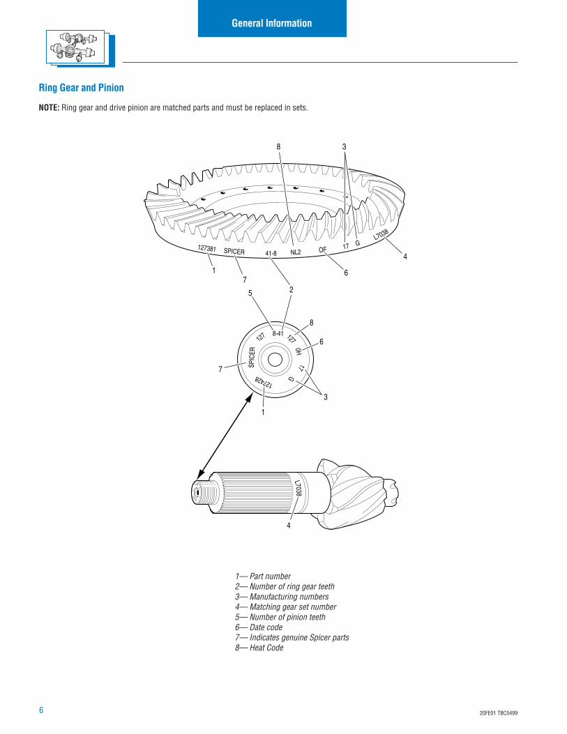
Ring Gear and Pinion
NOTE: Ring gear and drive pinion are matched parts and must be replaced in sets.
1— Part number2— Number of ring gear teeth3— Manufacturing numbers4— Matching gear set number5— Number of pinion teeth6— Date code7— Indicates genuine Spicer parts8— Heat Code
41-8SPICER127381 OFNL2
17
127 8-41
127428
SPIC
ER
17G
6-39JD77
8540
5
EATON 86
5 2
3
1
7
8
L70381
4
L7038
4
7
G
3
1270H
6
8
6
720FE01 TBC5499
Inspection
Failure Analysis
Failure analysis is the process of determining the original cause of acomponent failure in order to keep it from happening again. Toooften, when a failed component is replaced without determining itscause, there will be a recurring failure. If a carrier housing is opened,revealing a ring gear with a broken tooth, it is not enough to settle onthe broken tooth as the cause of the carrier failure. Other parts of thecarrier must be examined. For a thorough understanding of the failureand possible insight into related problems, the technician needs toobserve the overall condition of the vehicle.
No one benefits when a failed component goes on the junk pile withthe cause unknown. Nothing is more disturbing to a customer than arepeat failure. Systematically analyzing a failure to prevent a repeatoccurrence assures quality service by avoiding unnecessarydowntime and further expense to the customer.
The true cause of a failure can be better determined by knowing whatto look for, determining how a piece of the equipment was runningand learning about previous problems. In the case of a rebuilt rearaxle, mismatched gears may have been installed.
The more successful shops prevent repeat equipment failures bydeveloping good failure analysis practices. Knowing how to diagnosethe cause of a premature failure is one of the prerequisites of a goodheavy-equipment technician.
How to Diagnose a Failure
The following five steps are an effective approach to good failurediagnostics.
1. Document the problem.
2. Make a preliminary investigation.
3. Prepare the parts for inspection.
4. Find the cause of the failure
5. Correct the cause of the problem.
Document the Problem
Here are some guidelines for starting to learn about a failure,including questions to ask:
• Talk to the operator of the truck.
• Look at the service records.
• Find out when the truck was last serviced.
• Ask: In what type of service is the truck being used?
• Ask: Has this particular failure occurred before?
• Ask: How was the truck working prior to the failure?
You need to be a good listener. Sometimes, insignificant or unrelatedsymptoms can point to the cause of the failure.
• Ask: Was the vehicle operating at normal temperatures?
• Ask: Were the gauges showing normal ranges of opera-tion?
• Ask: Was there any unusual noise or vibration?
After listening, review the previous repair and maintenance records. Ifthere is more than one driver, talk to all of them and compare theirobservations for consistency with the service and maintenancerecords. Verify the chassis Vehicle Identification Number (VIN)number from the vehicle identification plate, as well as the mileageand hours on the vehicle.
Make a Preliminary Investigation
These steps consist of external inspections and observations that willbe valuable when combine with the results of the parts examination.
• Look for leaks, cracks or other damage that can point tothe cause of the failure.
• Make note of obvious leaks around plugs and seals. Amissing fill or drain plug would be an obvious cause forconcern.
• Look for cracks in the carrier housing (harder to see, butsometimes visible).
• Does the general mechanical condition of the vehicleindicate proper maintenance or are there signs of neglect?
• Are the tires in good condition and do the sizes match?
• If equipped with a torque-limiting device, is it workingproperly?
During the preliminary investigation, write down anything out of theordinary for later reference. Items that appear insignificant now maytake on more importance when the subassemblies are torn down.
8 20FE01 TBC5499
Inspection
Prepare the Parts for Inspection
After the preliminary investigation, locate the failure and prepare thepart for examination. In carrier failure analysis, it may be necessary todisassemble the unit.
• When disassembling subassemblies and parts, do notclean the parts immediately since cleaning may destroysome of the evidence.
• When tearing down the drive axle, do it in the recom-mended manner. Minimize any further damage to the unit.
• Ask more questions when examining the interior of thecarrier. Does the lubricant meet the manufacturer specifica-tions regarding quality, quantity and viscosity? As soon asyou have located the failed part, take time to analyze thedata.
Find the Cause of the Failure
Here begins the real challenge to determine the exact cause of thefailure. Keep in mind that there is no benefit to replacing a failed partwithout determining the cause of the failure. For example, afterexamining a failed part and finding that the failure is caused by a lackof lubrication, you must determine if there was an external leak.Obviously, if there is an external leak, just replacing the failed gear isnot going to correct the situation.
Another important consideration here is to determine the specifictype of failure which can be a valuable indicator for the cause offailure. The following pages show different types of failures andpossible causes. Use this as a guide in determining types of failuresand in correcting problems.
Correct the Cause of the Problem
Once the cause of the problem has been determine, refer to theappropriate service manual to perform the repairs.
920FE01 TBC5499
Inspection
Clean
1. Wash steel parts with ground or polished surfaces in solvent.There are many suitable commercial solvents available.Kerosene and diesel fuel are acceptable.
WARNING: Gasoline is not an acceptable solvent becauseof its extreme combustibility. It is unsafe in the workshopenvironment.
2. Wash castings or other rough parts in solvent or clean in hotsolution tanks using mild alkali solutions.
NOTE: If a hot solution tank is used, make sure parts are heatedthoroughly before rinsing.
3. Rinse thoroughly to remove all traces of the cleaningsolution.
4. Dry parts immediately with clean rags.
5. Oil parts.
• If parts are to be reused immediately: Lightly oil.
• If parts are to be stored: Coat with oil, wrap in corrosionresistant paper and store in a clean, dry place.
Inspect Axle Housing
Axle housing inspection and repairs are limited to the followingchecks or repairs.
• Visually inspect axle housing for cracks, nicks and burrs onmachined surfaces.
• Check carrier bolt holes and studs for foreign material.
• Replace damaged fasteners. Look for loose studs or cross-threaded holes.
CAUTION: Any damage which affects the alignment orstructural integrity of the housing requires housingreplacement. Do not repair by bending or straightening.This process can affect the material's properties and causeit to fail completely under load.
• Check all seals and gaskets.
NOTE: Replace conventional gaskets with silicone rubber gasketcompound (included in many repair kits). The compound provides amore effective seal against lube seepage and is easier to remove frommating surfaces when replacing parts.
Inspection
Inspect Components
Inspect all steel parts for:
• Notches, visible steps or grooves created by wear
• Pitting or cracking along gear contact lines
• Scuffing, deformation or discolorations. These are signs ofexcessive heat in the axle and are usually related to lowlubrication levels or improper lubrication practices.
In addition, inspect the following for damage:
• Differential gearing
• Bearings for loose fit on drive pinion, pilot bearing, anddifferential bearings
• All fasteners for rounded heads, bends, cracks or damagedthreads.
• Inspect machined surfaces of cast or malleable parts. Theymust be free of nicks, burrs, cracks, scoring, and wear.
• Look for elongation of drilled holes, wear on surfacesmachined for bearing fits and nicks or burrs in matingsurfaces.
Inspect Primary Gearing
Before reusing a primary gear set, inspect teeth for signs ofexcessive wear. Check tooth contact pattern for evidence ofincorrect adjustment.
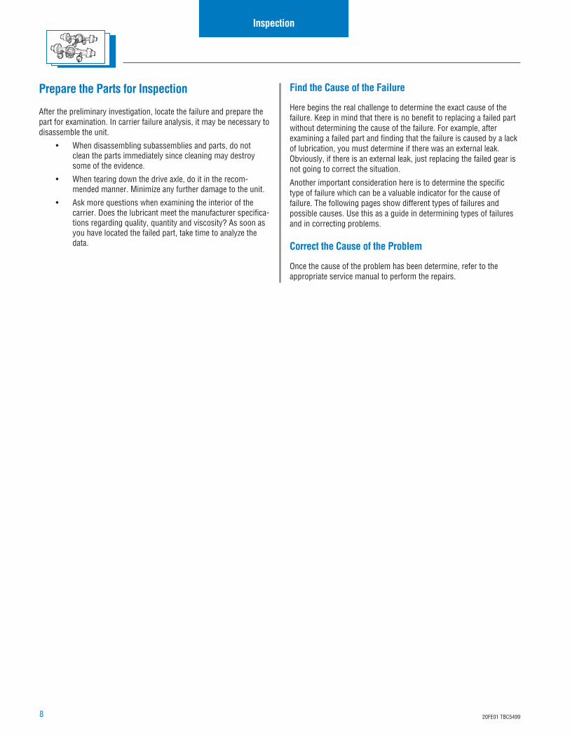
1— Axle housing2— Machined surface
1
2
10 20FE01 TBC5499
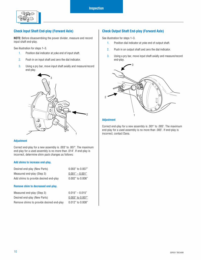
Check Output Shaft End-play (Forward Axle)
See illustration for steps 1–3.
1. Position dial indicator at yoke end of output shaft.
2. Push in on output shaft and zero the dial indicator.
3. Using a pry bar, move input shaft axially and measure/recordend-play.
Adjustment
Correct end-play for a new assembly is .001" to .005". The maximumend-play for a used assembly is no more than .005". If end-play isincorrect, contact Dana.
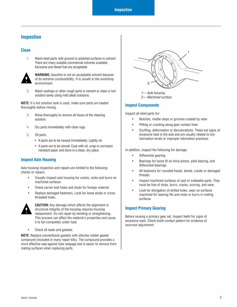
Check Input Shaft End-play (Forward Axle)
NOTE: Before disassembling the power divider, measure and recordinput shaft end-play.
See illustration for steps 1–3.
1. Position dial indicator at yoke end of input shaft.
2. Push in on input shaft and zero the dial indicator.
3. Using a pry bar, move input shaft axially and measure/recordend-play.
Adjustment
Correct end-play for a new assembly is .003" to .007". The maximumend-play for a used assembly is no more than .014". If end-play isincorrect, determine shim pack changes as follows:
Add shims to increase end-play.
Desired end-play (New Parts) 0.003” to 0.007”
Measured end-play (Step 3) 0.001” – 0.001”
Add shims to provide desired end-play 0.002” to 0.006”
Remove shim to decreased end-play.
Measured end-play (Step 3) 0.015” – 0.015”
Desired end-play (New Parts) 0.003” to 0.007”
Remove shims to provide desired end-play 0.012” to 0.008”
Inspection
1
2
3
1
2
3
1120FE01 TBC5499
Remove Differential Carrier(Forward and Rear)
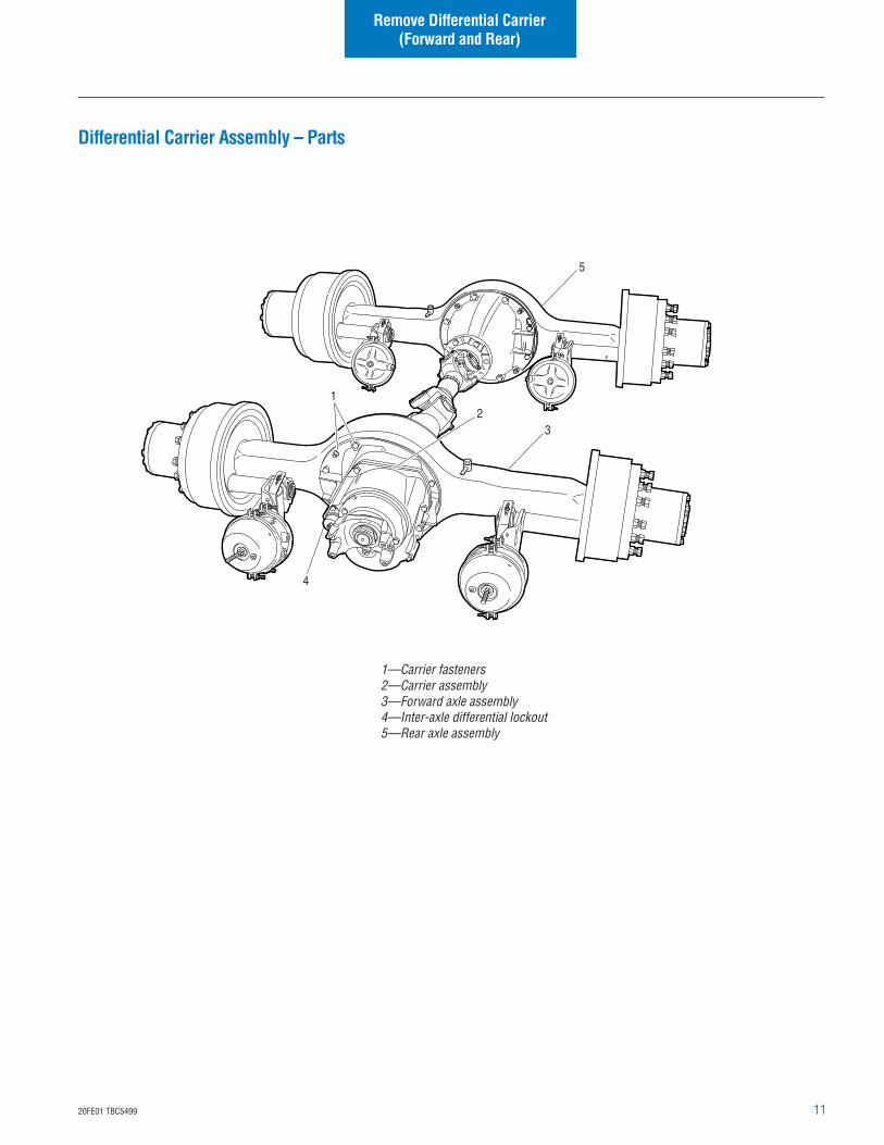
1—Carrier fasteners2—Carrier assembly3—Forward axle assembly4—Inter-axle differential lockout5—Rear axle assembly
Differential Carrier Assembly – Parts
12
3
4
5
12 20FE01 TBC5499
Remove Differential Carrier(Forward and Rear)
Remove Differential Carrier (Forward and Rear)
NOTE: The removal of the forward carrier does not require discon-necting of the inter-axle driveline and removal of the output shaftyoke assembly as most other Dana tandems require.
Standard Differentials
1. Block the vehicle.
2. Drain axle lubricant.
3. Rear Only: Disconnect inter-axle driveline.
4. Front Only: Disconnect main driveline.
5. Front Only: Disconnect differential lockout air line.
6. Disconnect lead wires to the selector switch and air line atshift cylinder.
7. Remove axle shafts.
Diff-Lock Models
For removal of the locking wheel differential carrier assembly, thedifferential lock must be engaged and held in the engaged position.This can be accomplished by one of two methods; either engage viaair pressure or engage manually.
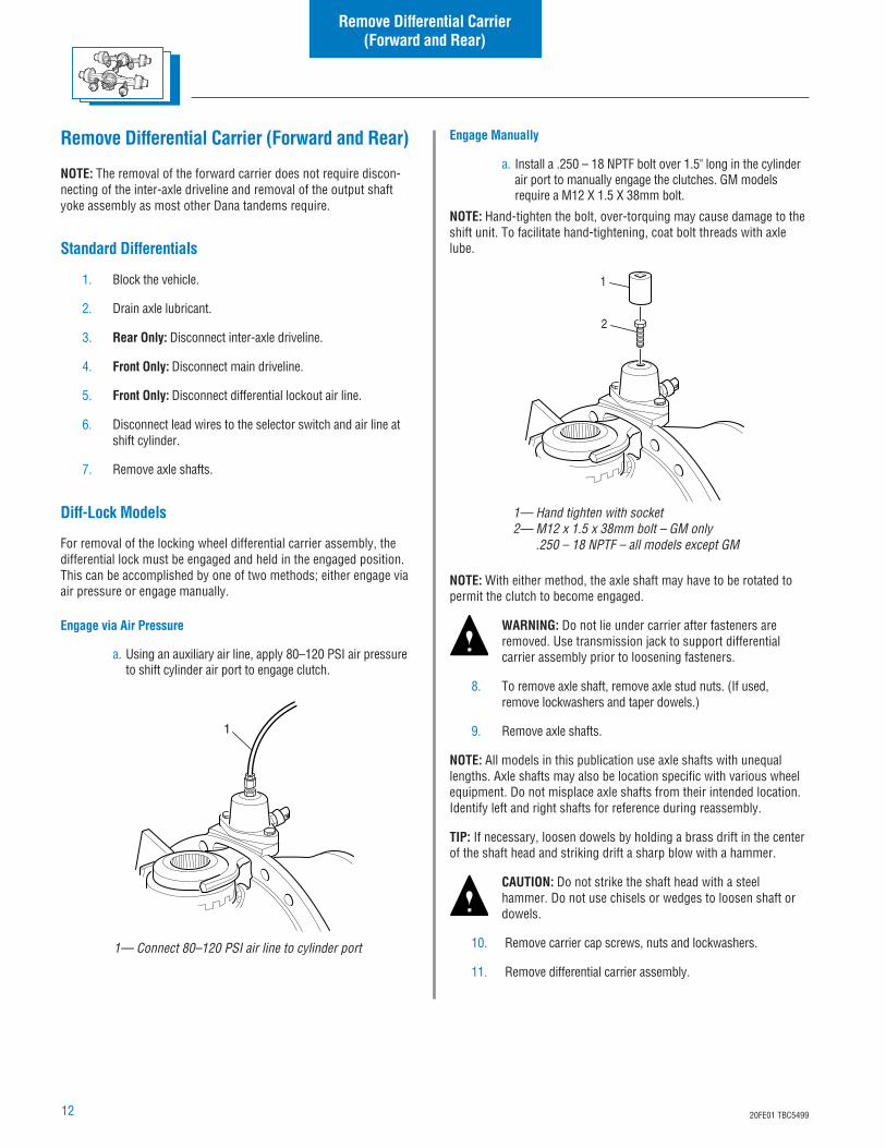
Engage via Air Pressure
a. Using an auxiliary air line, apply 80–120 PSI air pressureto shift cylinder air port to engage clutch.
1— Connect 80–120 PSI air line to cylinder port
1
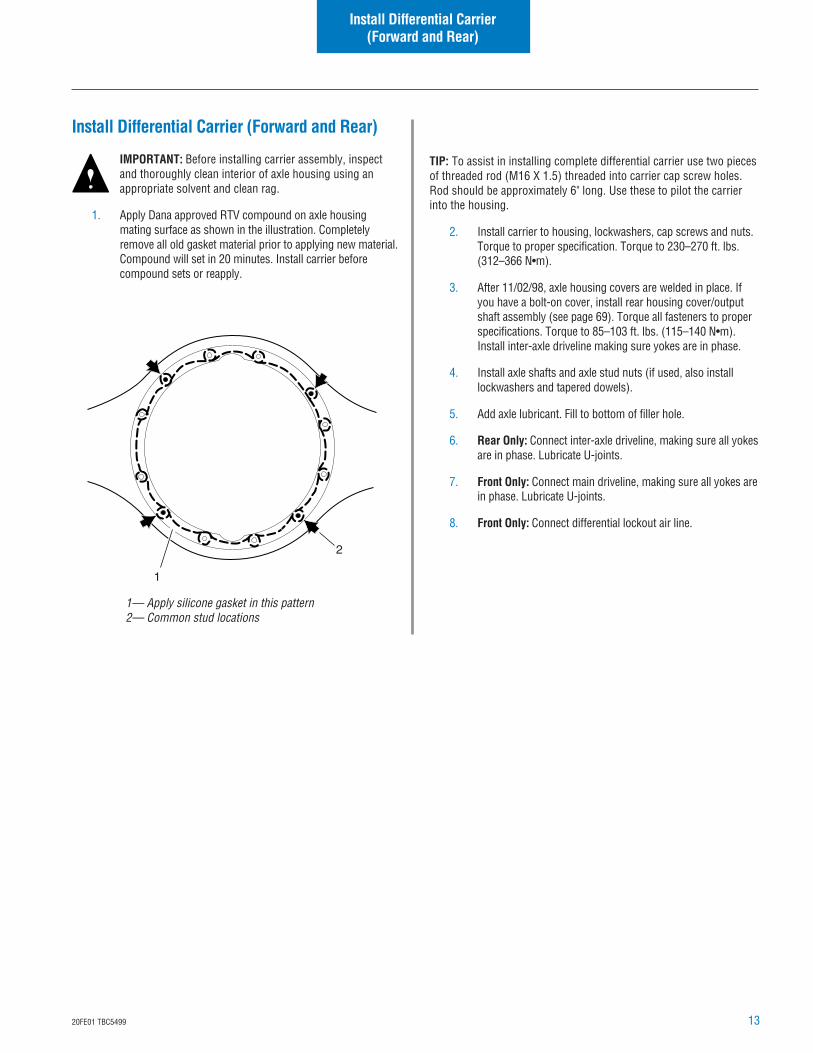
Engage Manually
a. Install a .250 – 18 NPTF bolt over 1.5" long in the cylinderair port to manually engage the clutches. GM modelsrequire a M12 X 1.5 X 38mm bolt.
NOTE: Hand-tighten the bolt, over-torquing may cause damage to theshift unit. To facilitate hand-tightening, coat bolt threads with axlelube.
NOTE: With either method, the axle shaft may have to be rotated topermit the clutch to become engaged.
WARNING: Do not lie under carrier after fasteners areremoved. Use transmission jack to support differentialcarrier assembly prior to loosening fasteners.
8. To remove axle shaft, remove axle stud nuts. (If used,remove lockwashers and taper dowels.)
9. Remove axle shafts.
NOTE: All models in this publication use axle shafts with unequallengths. Axle shafts may also be location specific with various wheelequipment. Do not misplace axle shafts from their intended location.Identify left and right shafts for reference during reassembly.
TIP: If necessary, loosen dowels by holding a brass drift in the centerof the shaft head and striking drift a sharp blow with a hammer.
CAUTION: Do not strike the shaft head with a steelhammer. Do not use chisels or wedges to loosen shaft ordowels.
10. Remove carrier cap screws, nuts and lockwashers.
11. Remove differential carrier assembly.
1
2
1— Hand tighten with socket2— M12 x 1.5 x 38mm bolt – GM only
.250 – 18 NPTF – all models except GM
1320FE01 TBC5499
Install Differential Carrier (Forward and Rear)
IMPORTANT: Before installing carrier assembly, inspectand thoroughly clean interior of axle housing using anappropriate solvent and clean rag.
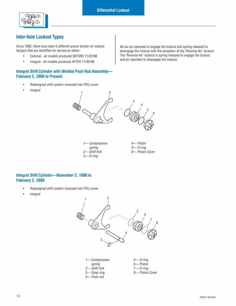
1. Apply Dana approved RTV compound on axle housingmating surface as shown in the illustration. Completelyremove all old gasket material prior to applying new material.Compound will set in 20 minutes. Install carrier beforecompound sets or reapply.
Install Differential Carrier(Forward and Rear)
1— Apply silicone gasket in this pattern2— Common stud locations
1
2
TIP: To assist in installing complete differential carrier use two piecesof threaded rod (M16 X 1.5) threaded into carrier cap screw holes.Rod should be approximately 6" long. Use these to pilot the carrierinto the housing.
2. Install carrier to housing, lockwashers, cap screws and nuts.Torque to proper specification. Torque to 230–270 ft. lbs.(312–366 N•m).
3. After 11/02/98, axle housing covers are welded in place. Ifyou have a bolt-on cover, install rear housing cover/outputshaft assembly (see page 69). Torque all fasteners to properspecifications. Torque to 85–103 ft. lbs. (115–140 N•m).Install inter-axle driveline making sure yokes are in phase.
4. Install axle shafts and axle stud nuts (if used, also installlockwashers and tapered dowels).
5. Add axle lubricant. Fill to bottom of filler hole.
6. Rear Only: Connect inter-axle driveline, making sure all yokesare in phase. Lubricate U-joints.
7. Front Only: Connect main driveline, making sure all yokes arein phase. Lubricate U-joints.
8. Front Only: Connect differential lockout air line.
14 20FE01 TBC5499
Inter-Axle Lockout Types
Since 1992, there have been 5 different power divider air lockoutdesigns that are identified for service as either:
• External - all models produced BEFORE 11/02/98
• Integral - all models produced AFTER 11/02/98
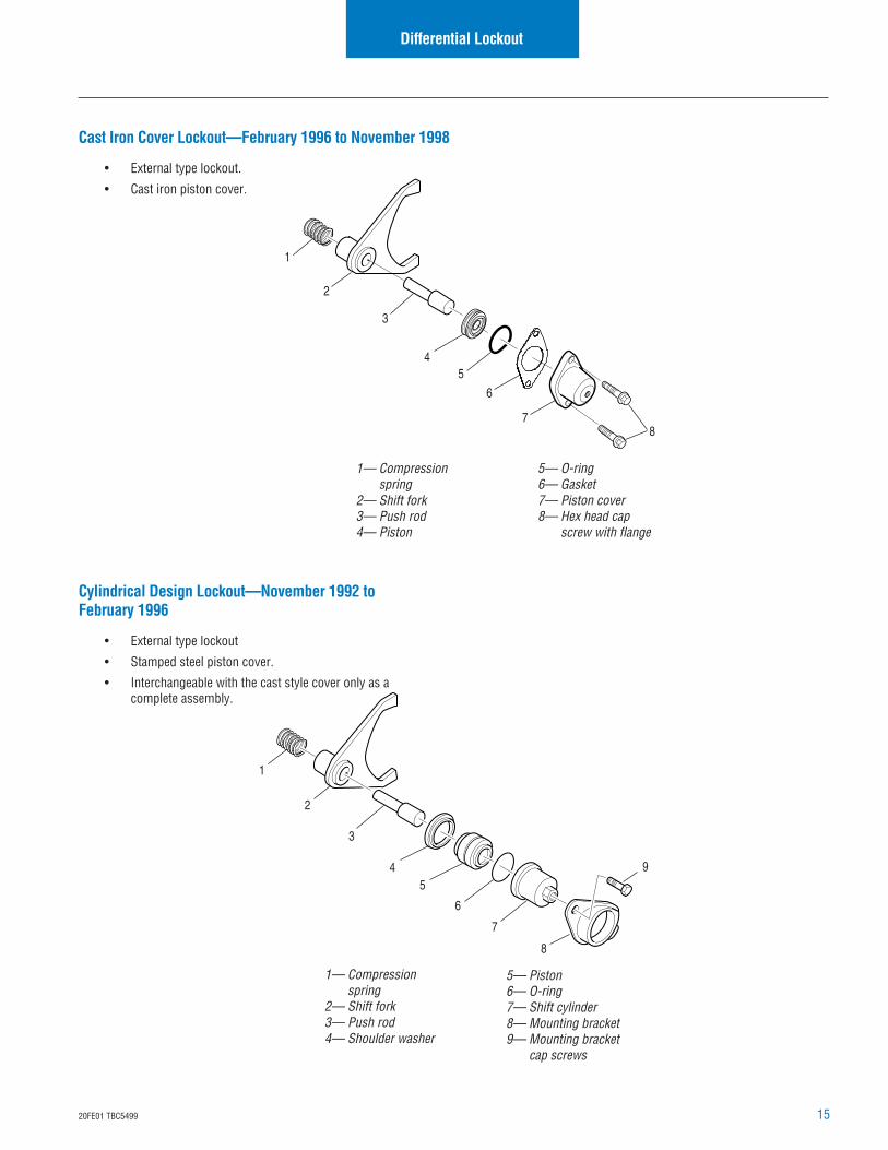
Integral Shift Cylinder with Welded Push Rod Assembly—February 2, 2000 to Present
• Redesigned shift system recessed into PDU cover.
• Integral
All are air-operated to engage the lockout and spring-released todisengage the lockout with the exception of the "Reverse-Air" lockout.The "Reverse-Air" lockout is spring-released to engage the lockoutand air-operated to disengage the lockout.
1— Compressionspring
2— Shift fork3— Snap ring4— Push rod
5— O-ring6— Piston7— O-ring8— Piston Cover
1— Compressionspring
2— Shift fork3— O-ring
4— Piston5— O-ring6— Piston Cover
Integral Shift Cylinder—November 2, 1998 toFebruary 2, 2000
• Redesigned shift system recessed into PDU cover.
• Integral
Differential Lockout
1 2
34
56
1 2
4
3
56
78
1520FE01 TBC5499
Differential Lockout
Cylindrical Design Lockout—November 1992 toFebruary 1996
• External type lockout
• Stamped steel piston cover.
• Interchangeable with the cast style cover only as acomplete assembly.
1— Compressionspring
2— Shift fork3— Push rod4— Shoulder washer
5— Piston6— O-ring7— Shift cylinder8— Mounting bracket9— Mounting bracket
cap screws
1— Compressionspring
2— Shift fork3— Push rod4— Piston
5— O-ring6— Gasket7— Piston cover8— Hex head cap
screw with flange
1
2
3
45
6
7
8
9
Cast Iron Cover Lockout—February 1996 to November 1998
• External type lockout.
• Cast iron piston cover.
1
2
3
45
6
78
16 20FE01 TBC5499
Differential Lockout
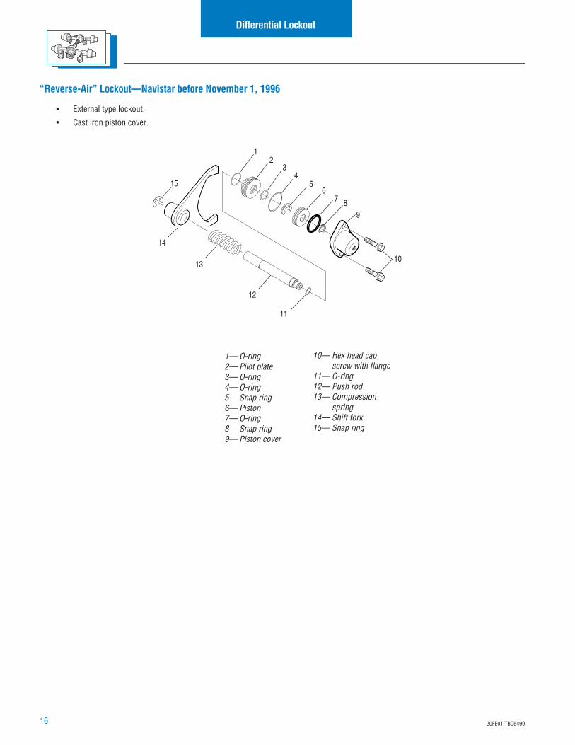
1— O-ring2— Pilot plate3— O-ring4— O-ring5— Snap ring6— Piston7— O-ring8— Snap ring9— Piston cover
10— Hex head capscrew with flange
11— O-ring12— Push rod13— Compression
spring14— Shift fork15— Snap ring
10
987
65
43
21
12
11
15
14
13
“Reverse-Air” Lockout—Navistar before November 1, 1996
• External type lockout.
• Cast iron piston cover.
1720FE01 TBC5499
Differential Lockout
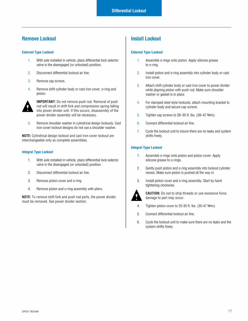
Remove Lockout
External Type Lockout
1. With axle installed in vehicle, place differential lock selectorvalve in the disengaged (or unlocked) position.
2. Disconnect differential lockout air line.
3. Remove cap screws.
4. Remove shift cylinder body or cast iron cover, o-ring andpiston.
IMPORTANT: Do not remove push rod. Removal of pushrod will result in shift fork and compression spring fallinginto power divider unit. If this occurs, disassembly of thepower divider assembly will be necessary.
5. Remove shoulder washer in cylindrical design lockouts. Castiron cover lockout designs do not use a shoulder washer.
NOTE: Cylindrical design lockout and cast iron cover lockout areinterchangeable only as complete assemblies.
Integral Type Lockout
1. With axle installed in vehicle, place differential lock selectorvalve in the disengaged (or unlocked) position.
2. Disconnect differential lockout air line.
3. Remove piston cover and o-ring.
4. Remove piston and o-ring assembly with pliers.
NOTE: To remove shift fork and push rod parts, the power dividermust be removed. See power divider section.
Install Lockout
External Type Lockout
1. Assemble o-rings onto piston. Apply silicone greaseto o-ring.
2. Install piston and o-ring assembly into cylinder body or castiron cover.
3. Attach shift cylinder body or cast iron cover to power dividerwhile aligning piston with push rod. Make sure shoulderwasher or gasket is in place.
4. For stamped steel style lockouts, attach mounting bracket tocylinder body and secure cap screws.
5. Tighten cap screws to 28–35 ft. lbs. (38–47 N•m).
6. Connect differential lockout air line.
7. Cycle the lockout unit to insure there are no leaks and systemshifts freely.
Integral Type Lockout
1. Assemble o-rings onto piston and piston cover. Applysilicone grease to o-rings.
2. Gently push piston and o-ring assembly into lockout cylinderrecess. Make sure piston is pushed all the way in.
3. Install piston cover and o-ring assembly. Start by handtightening clockwise.
CAUTION: Do not to strip threads or use excessive force,damage to part may occur.
4. Tighten piston cover to 25-35 ft. lbs. (35-47 N•m).
5. Connect differential lockout air line.
6. Cycle the lockout unit to make sure there are no leaks and thesystem shifts freely.
18 20FE01 TBC5499
Power Divider
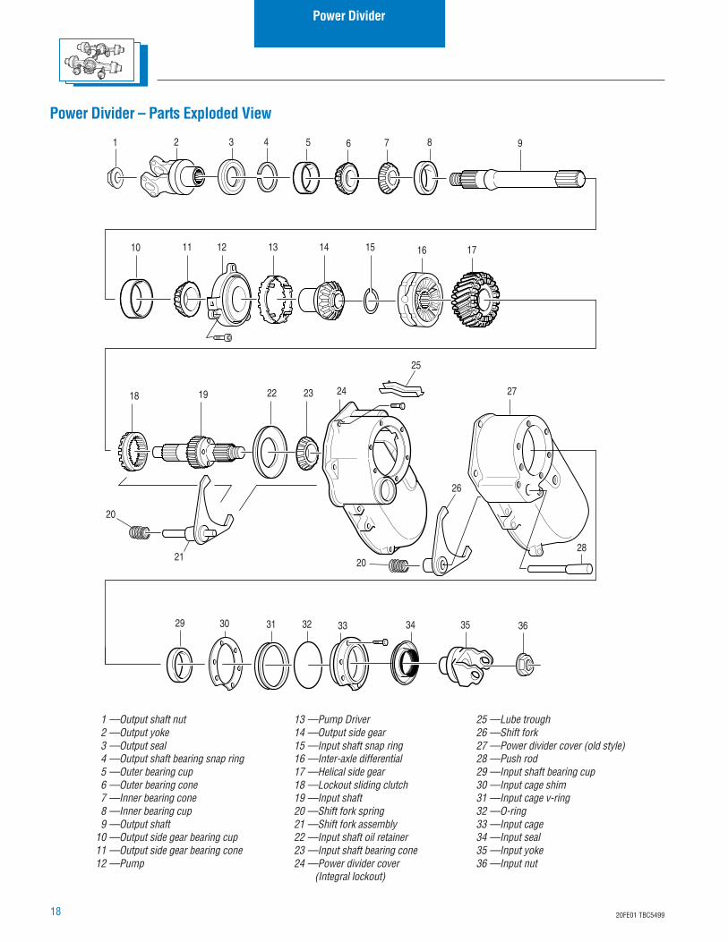
Power Divider – Parts Exploded View
1 —Output shaft nut2 —Output yoke3 —Output seal4 —Output shaft bearing snap ring5 —Outer bearing cup6 —Outer bearing cone7 —Inner bearing cone8 —Inner bearing cup9 —Output shaft
10 —Output side gear bearing cup11 —Output side gear bearing cone12 —Pump
13 —Pump Driver14 —Output side gear15 —Input shaft snap ring16 —Inter-axle differential17 —Helical side gear18 —Lockout sliding clutch19 —Input shaft20 —Shift fork spring21 —Shift fork assembly22 —Input shaft oil retainer23 —Input shaft bearing cone24 —Power divider cover
(Integral lockout)
25 —Lube trough26 —Shift fork27 —Power divider cover (old style)28 —Push rod29 —Input shaft bearing cup30 —Input cage shim31 —Input cage v-ring32 —O-ring33 —Input cage34 —Input seal35 —Input yoke36 —Input nut
18 19
10 14131211 15
30 33 3531 32 34 3629
16
7 91 3 52 4 6 8
17
22 23 24
21
26
27
28
25
20
20
1920FE01 TBC5499
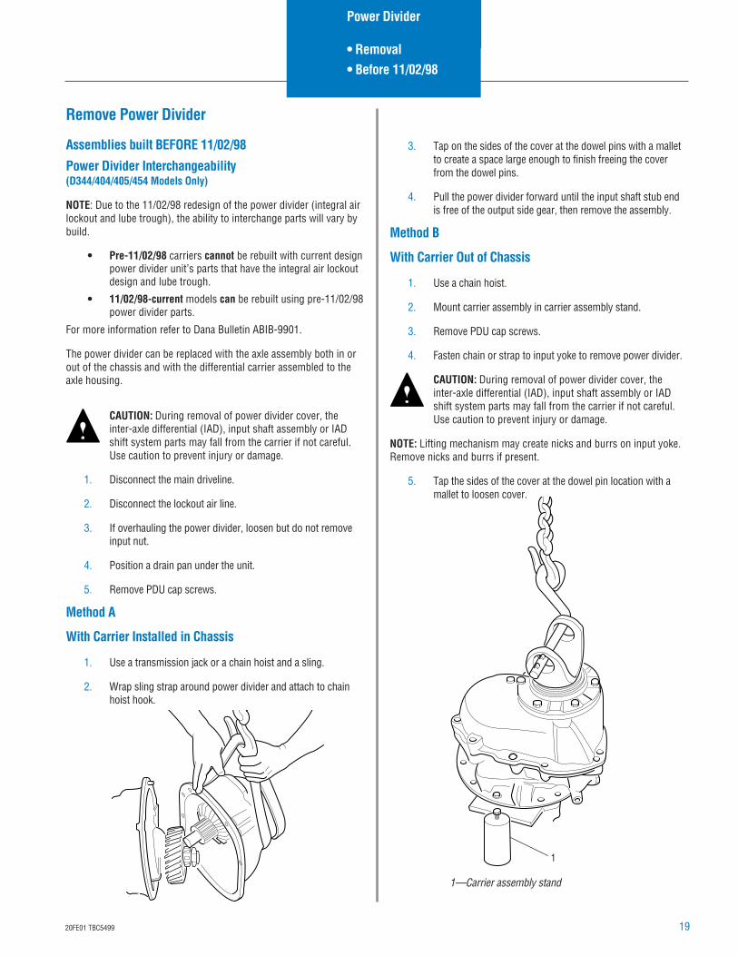
1—Carrier assembly stand
1
Remove Power Divider
Assemblies built BEFORE 11/02/98
Power Divider Interchangeability(D344/404/405/454 Models Only)
NOTE: Due to the 11/02/98 redesign of the power divider (integral airlockout and lube trough), the ability to interchange parts will vary bybuild.
• Pre-11/02/98 carriers cannot be rebuilt with current designpower divider unit’s parts that have the integral air lockoutdesign and lube trough.
• 11/02/98-current models can be rebuilt using pre-11/02/98power divider parts.
For more information refer to Dana Bulletin ABIB-9901.
The power divider can be replaced with the axle assembly both in orout of the chassis and with the differential carrier assembled to theaxle housing.
CAUTION: During removal of power divider cover, theinter-axle differential (IAD), input shaft assembly or IADshift system parts may fall from the carrier if not careful.Use caution to prevent injury or damage.
1. Disconnect the main driveline.
2. Disconnect the lockout air line.
3. If overhauling the power divider, loosen but do not removeinput nut.
4. Position a drain pan under the unit.
5. Remove PDU cap screws.
Method A
With Carrier Installed in Chassis
1. Use a transmission jack or a chain hoist and a sling.
2. Wrap sling strap around power divider and attach to chainhoist hook.
Power Divider
• Removal• Before 11/02/98
3. Tap on the sides of the cover at the dowel pins with a malletto create a space large enough to finish freeing the coverfrom the dowel pins.
4. Pull the power divider forward until the input shaft stub endis free of the output side gear, then remove the assembly.
Method B
With Carrier Out of Chassis
1. Use a chain hoist.
2. Mount carrier assembly in carrier assembly stand.
3. Remove PDU cap screws.
4. Fasten chain or strap to input yoke to remove power divider.
CAUTION: During removal of power divider cover, theinter-axle differential (IAD), input shaft assembly or IADshift system parts may fall from the carrier if not careful.Use caution to prevent injury or damage.
NOTE: Lifting mechanism may create nicks and burrs on input yoke.Remove nicks and burrs if present.
5. Tap the sides of the cover at the dowel pin location with amallet to loosen cover.
20 20FE01 TBC5499
Disassemble, Assemble and Overhaul thePower Divider
Assemblies built BEFORE 11/02/98
The power divider may be serviced with the carrier assembly in or outof the axle housing.
NOTE: The following procedure assumes that the differential carrierhas been removed from the axle housing and that the power dividerhas been removed from the carrier assembly.
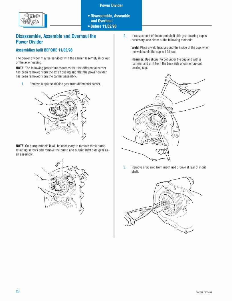
1. Remove output shaft side gear from differential carrier.
NOTE: On pump models it will be necessary to remove three pumpretaining screws and remove the pump and output shaft side gear asan assembly.
2. If replacement of the output shaft side gear bearing cup isnecessary, use either of the following methods:
Weld: Place a weld bead around the inside of the cup, whenthe weld cools the cup will fall out.
Hammer: Use slipper to get under the cup and with ahammer and drift from the back side of carrier tap outbearing cup.
3. Remove snap ring from machined groove at rear of inputshaft.
Power Divider
• Disassemble, Assemble and Overhaul• Before 11/02/98
2120FE01 TBC5499
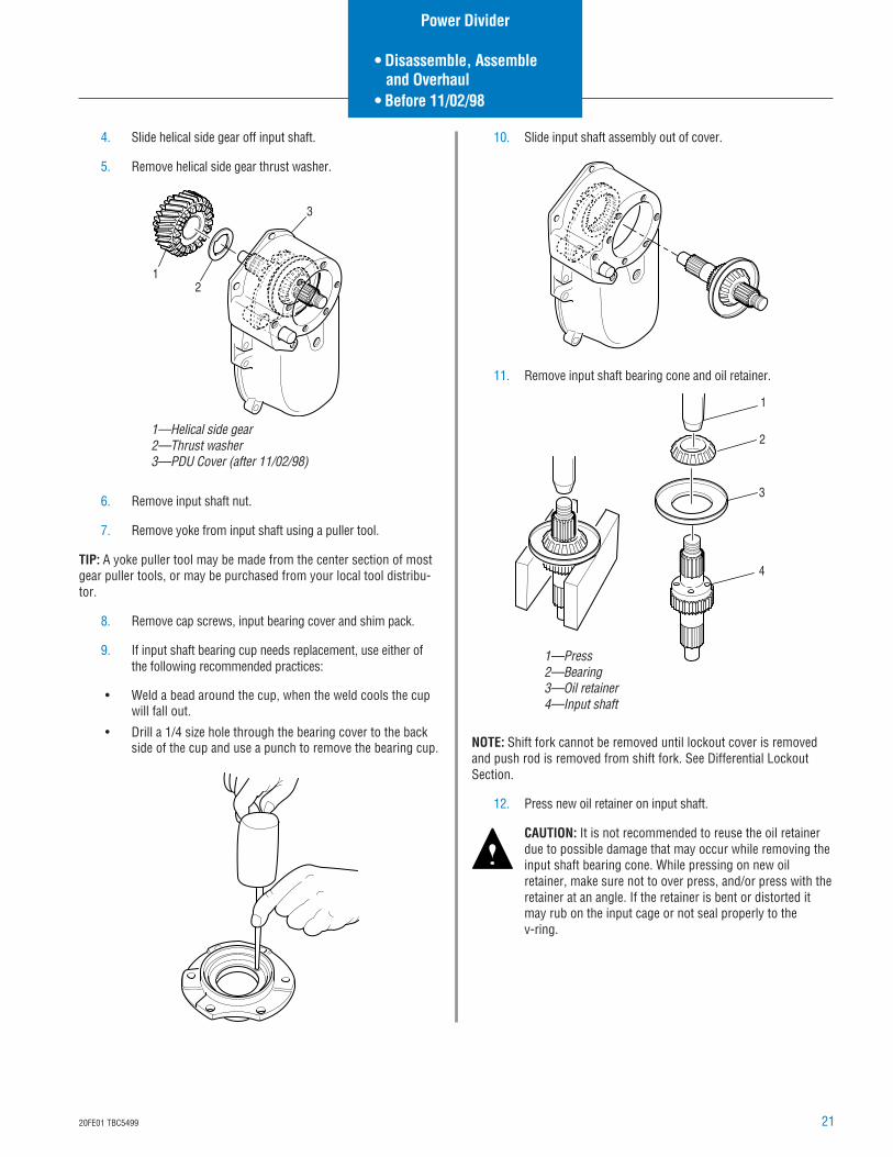
4. Slide helical side gear off input shaft.
5. Remove helical side gear thrust washer.
6. Remove input shaft nut.
7. Remove yoke from input shaft using a puller tool.
TIP: A yoke puller tool may be made from the center section of mostgear puller tools, or may be purchased from your local tool distribu-tor.
8. Remove cap screws, input bearing cover and shim pack.
9. If input shaft bearing cup needs replacement, use either ofthe following recommended practices:
• Weld a bead around the cup, when the weld cools the cupwill fall out.
• Drill a 1/4 size hole through the bearing cover to the backside of the cup and use a punch to remove the bearing cup.
12
3
1—Helical side gear2—Thrust washer3—PDU Cover (after 11/02/98)
1
2
3
4
1—Press2—Bearing3—Oil retainer4—Input shaft
10. Slide input shaft assembly out of cover.
11. Remove input shaft bearing cone and oil retainer.
NOTE: Shift fork cannot be removed until lockout cover is removedand push rod is removed from shift fork. See Differential LockoutSection.
12. Press new oil retainer on input shaft.
CAUTION: It is not recommended to reuse the oil retainerdue to possible damage that may occur while removing theinput shaft bearing cone. While pressing on new oilretainer, make sure not to over press, and/or press with theretainer at an angle. If the retainer is bent or distorted itmay rub on the input cage or not seal properly to thev-ring.
Power Divider
• Disassemble, Assemble and Overhaul• Before 11/02/98
22 20FE01 TBC5499
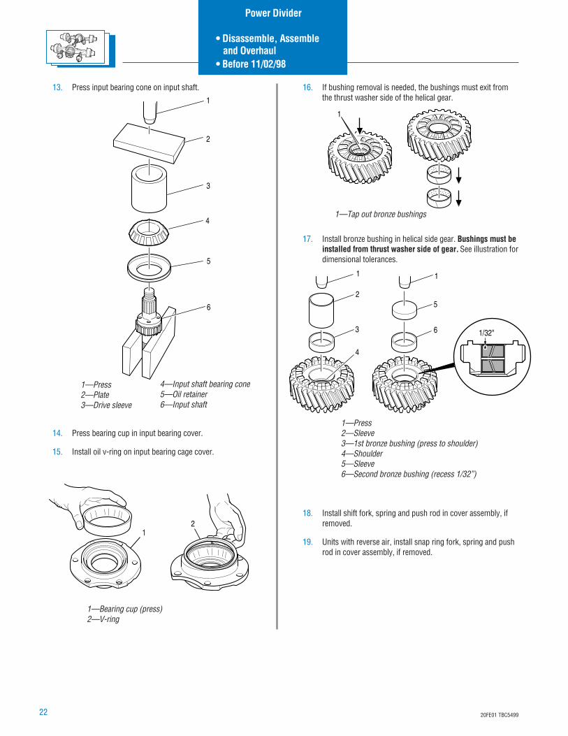
13. Press input bearing cone on input shaft.
14. Press bearing cup in input bearing cover.
15. Install oil v-ring on input bearing cage cover.
12
1—Bearing cup (press)2—V-ring
1
1—Tap out bronze bushings
16. If bushing removal is needed, the bushings must exit fromthe thrust washer side of the helical gear.
17. Install bronze bushing in helical side gear. Bushings must beinstalled from thrust washer side of gear. See illustration fordimensional tolerances.
18. Install shift fork, spring and push rod in cover assembly, ifremoved.
19. Units with reverse air, install snap ring fork, spring and pushrod in cover assembly, if removed.
3
1
2
4
6
1
5
1/32"
1—Press2—Sleeve3—1st bronze bushing (press to shoulder)4—Shoulder5—Sleeve6—Second bronze bushing (recess 1/32”)
5
3
2
1
6
4
1—Press2—Plate3—Drive sleeve
4—Input shaft bearing cone5—Oil retainer6—Input shaft
Power Divider
• Disassemble, Assemble and Overhaul• Before 11/02/98
2320FE01 TBC5499
12
3
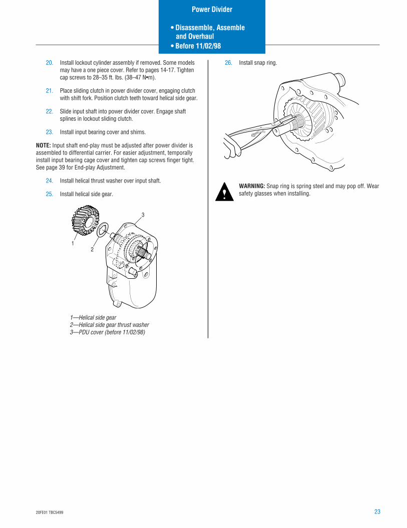
1—Helical side gear2—Helical side gear thrust washer3—PDU cover (before 11/02/98)
20. Install lockout cylinder assembly if removed. Some modelsmay have a one piece cover. Refer to pages 14-17. Tightencap screws to 28–35 ft. lbs. (38–47 N•m).
21. Place sliding clutch in power divider cover, engaging clutchwith shift fork. Position clutch teeth toward helical side gear.
22. Slide input shaft into power divider cover. Engage shaftsplines in lockout sliding clutch.
23. Install input bearing cover and shims.
NOTE: Input shaft end-play must be adjusted after power divider isassembled to differential carrier. For easier adjustment, temporallyinstall input bearing cage cover and tighten cap screws finger tight.See page 39 for End-play Adjustment.
24. Install helical thrust washer over input shaft.
25. Install helical side gear.
26. Install snap ring.
WARNING: Snap ring is spring steel and may pop off. Wearsafety glasses when installing.
Power Divider
• Disassemble, Assemble and Overhaul• Before 11/02/98
24 20FE01 TBC5499
Install Lube Pump
1. Install lube pump assembly onto output side gear.
NOTE: The lube pump assembly is a slip-fit on the output shaft sidegear, behind the press fit of the output shaft side gear bearing. Theoutput shaft side gear bearing cone positions the pump assemblyinto the carrier.
2. Install bearing cone on output side gear.
3. Press bearing using proper tools until fully seated.
4. Reinstall output side gear pump and bearing assembly intocarrier.
5. Tighten lube pump retaining screws to 17-21 ft. lbs.(23-38 N•m).
TIP: The lube pump assembly is orientated in such a way that thethree mounting/locating tabs will only line up one way.
NOTE: The lube pump is driven off the IAD assembly through a drivecoupling. The drive coupling has drive tangs to both the IADassembly and the lube pump. The IAD has notches that will acceptthe drive coupling on either face.
6. Install pump drive coupling.
NOTE: If reusing the IAD assembly, install in same direction asremoved.
7. Reinstall IAD.
CAUTION: Exercise care to direct compressed air into asafe area. Wear safety glasses.
Remove Lube Pump
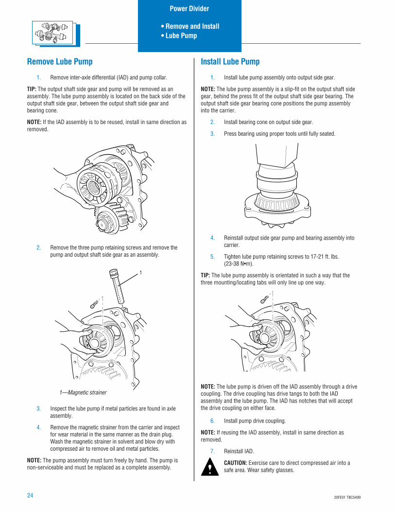
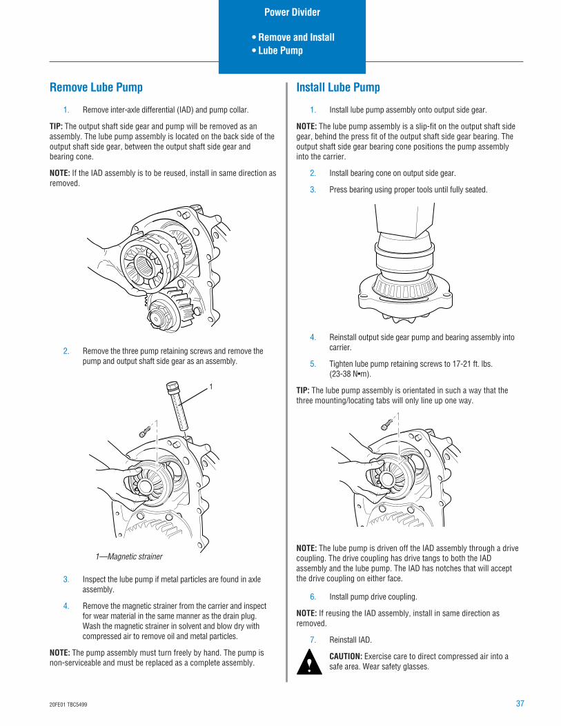
1. Remove inter-axle differential (IAD) and pump collar.
TIP: The output shaft side gear and pump will be removed as anassembly. The lube pump assembly is located on the back side of theoutput shaft side gear, between the output shaft side gear andbearing cone.
NOTE: If the IAD assembly is to be reused, install in same direction asremoved.
2. Remove the three pump retaining screws and remove thepump and output shaft side gear as an assembly.
3. Inspect the lube pump if metal particles are found in axleassembly.
4. Remove the magnetic strainer from the carrier and inspectfor wear material in the same manner as the drain plug.Wash the magnetic strainer in solvent and blow dry withcompressed air to remove oil and metal particles.
NOTE: The pump assembly must turn freely by hand. The pump isnon-serviceable and must be replaced as a complete assembly.
1
1—Magnetic strainer
Power Divider
• Remove and Install• Lube Pump
2520FE01 TBC5499
Install Power Divider to Carrier Assembly
Assemblies built BEFORE 11/02/98(In vehicle installations shown)
NOTE: Cleanliness in your work area is important as dirt is anabrasive and will cause premature wear of the otherwise serviceableparts.
NOTE: It is assumed that the differential carrier is secured in a stand,or the power divider only is being serviced while the axle is stillattached to the housing.
CAUTION: During installation of power divider cover, theinter-axle differential (IAD), input shaft assembly or IADshift system parts may fall from the carrier if not careful.Use caution to prevent injury or damage.
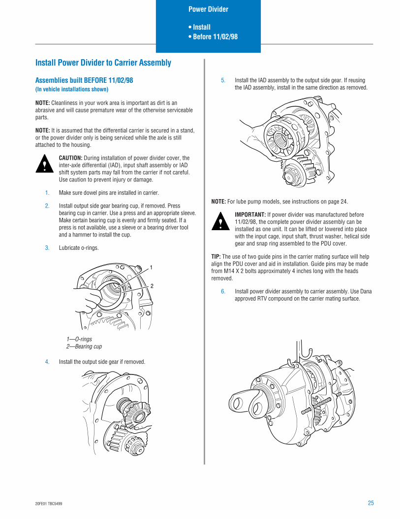
1. Make sure dowel pins are installed in carrier.
2. Install output side gear bearing cup, if removed. Pressbearing cup in carrier. Use a press and an appropriate sleeve.Make certain bearing cup is evenly and firmly seated. If apress is not available, use a sleeve or a bearing driver tooland a hammer to install the cup.
3. Lubricate o-rings.
4. Install the output side gear if removed.
1
2
1—O-rings2—Bearing cup
5. Install the IAD assembly to the output side gear. If reusingthe IAD assembly, install in the same direction as removed.
NOTE: For lube pump models, see instructions on page 24.
IMPORTANT: If power divider was manufactured before11/02/98, the complete power divider assembly can beinstalled as one unit. It can be lifted or lowered into placewith the input cage, input shaft, thrust washer, helical sidegear and snap ring assembled to the PDU cover.
TIP: The use of two guide pins in the carrier mating surface will helpalign the PDU cover and aid in installation. Guide pins may be madefrom M14 X 2 bolts approximately 4 inches long with the headsremoved.
6. Install power divider assembly to carrier assembly. Use Danaapproved RTV compound on the carrier mating surface.
Power Divider
• Install• Before 11/02/98
26 20FE01 TBC5499
CAUTION: During installation of power divider cover, theinter-axle differential (IAD), input shaft assembly or IADshift system parts may fall from the carrier if not careful.Use caution to prevent injury or damage.
7. During installation rotate input shaft to engage input shaftsplines with inter-axle differential. After installation, theoutput shaft should turn when the input shaft is rotated andoutput shaft should turn independently from the input shaft.
NOTE: Gasket compound will harden in 20 minutes. Install powerdivider as quickly as possible to avoid future leaks.
8. Install power divider cap screws. Torque to 114–140 ft. lbs.(155–190 N•m)
9. Reinstall input yoke if removed. All yokes have a slip tointerference fit on spline. Yokes should always be installedwith a press on tool to ensure they are fully seated.
10. Even though you may have checked the input shaft end-playbefore, you must check and adjust it again now, see page 40.
Power Divider
• Install• Before 11/02/98
2720FE01 TBC5499
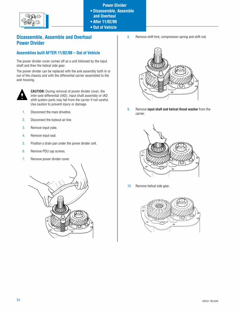
Disassemble, Assemble and OverhaulPower Divider
Assemblies built AFTER 11/02/98 (In Vehicle)
The power divider cover comes off as a unit followed by the inputshaft and then the helical side gear.
The power divider can be replaced with the axle assembly both in orout of the chassis and with the differential carrier assembled to theaxle housing.
CAUTION: During removal of power divider cover, theinter-axle differential (IAD), input shaft assembly or IADshift system parts may fall from the carrier if not careful.Use caution to prevent injury or damage.
1. Disconnect the main driveline.
2. Disconnect the lockout air line.
3. Remove input yoke.
4. Remove input seal.
5. Position a drain pan under the power divider unit.
6. Remove PDU cap screws.
7. Remove power divider cover.
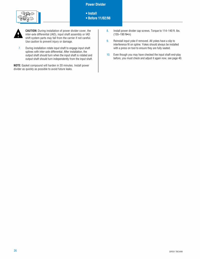
8. Remove shift fork, compression spring and shift rod.
9. Remove input shaft drive assembly from the carrier.
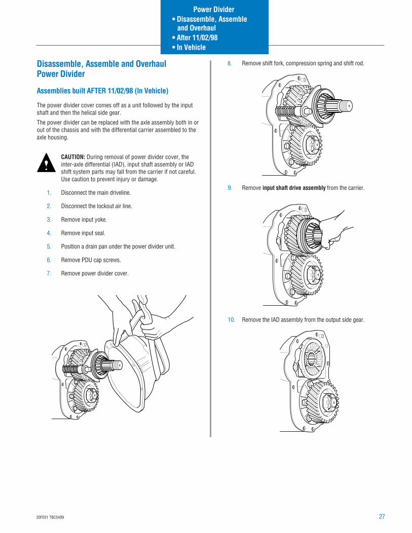
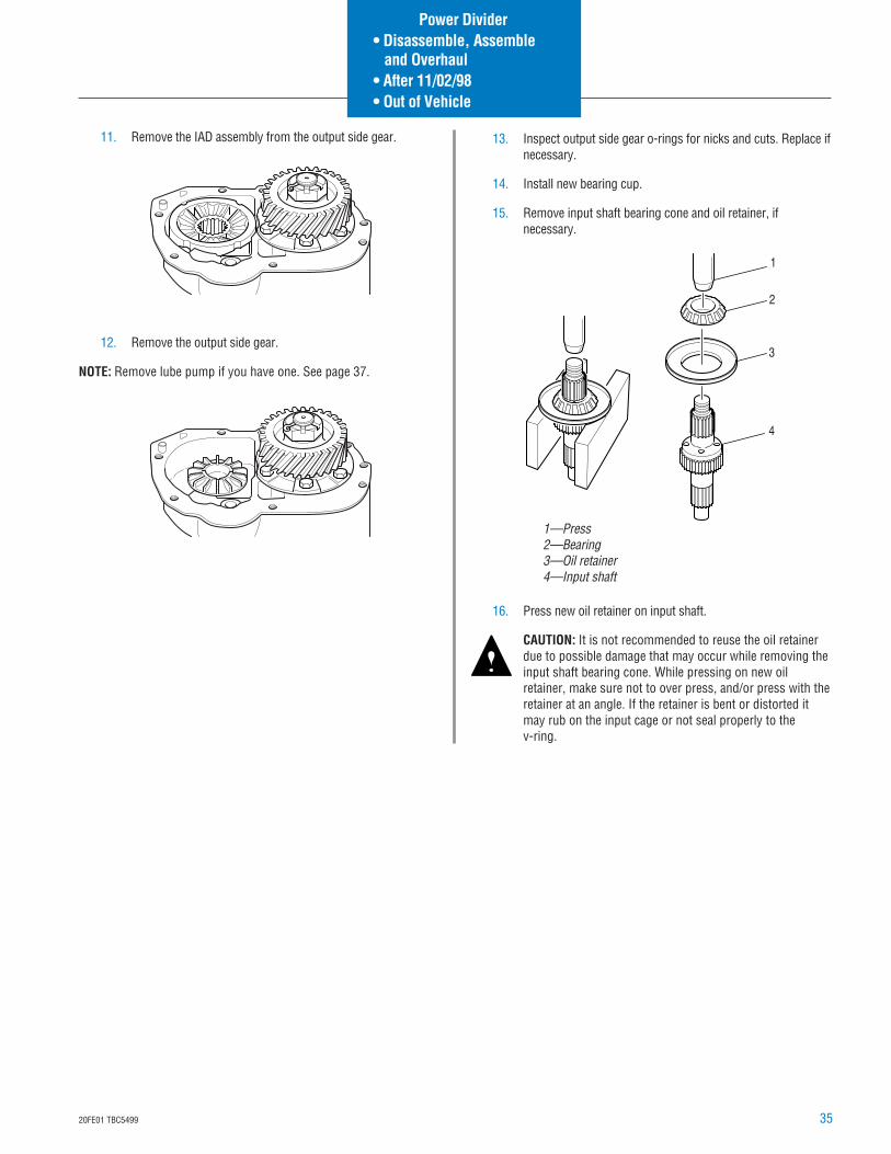
10. Remove the IAD assembly from the output side gear.
Power Divider• Disassemble, Assemble and Overhaul• After 11/02/98• In Vehicle
28 20FE01 TBC5499
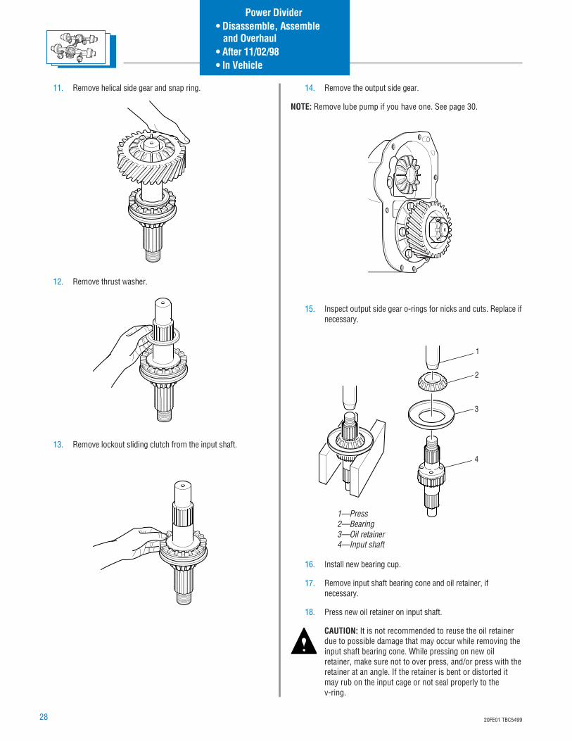
11. Remove helical side gear and snap ring.
12. Remove thrust washer.
13. Remove lockout sliding clutch from the input shaft.
14. Remove the output side gear.
NOTE: Remove lube pump if you have one. See page 30.
15. Inspect output side gear o-rings for nicks and cuts. Replace ifnecessary.
16. Install new bearing cup.
17. Remove input shaft bearing cone and oil retainer, ifnecessary.
18. Press new oil retainer on input shaft.
CAUTION: It is not recommended to reuse the oil retainerdue to possible damage that may occur while removing theinput shaft bearing cone. While pressing on new oilretainer, make sure not to over press, and/or press with theretainer at an angle. If the retainer is bent or distorted itmay rub on the input cage or not seal properly to thev-ring.
1
2
3
4
1—Press2—Bearing3—Oil retainer4—Input shaft
Power Divider• Disassemble, Assemble and Overhaul• After 11/02/98• In Vehicle
2920FE01 TBC5499
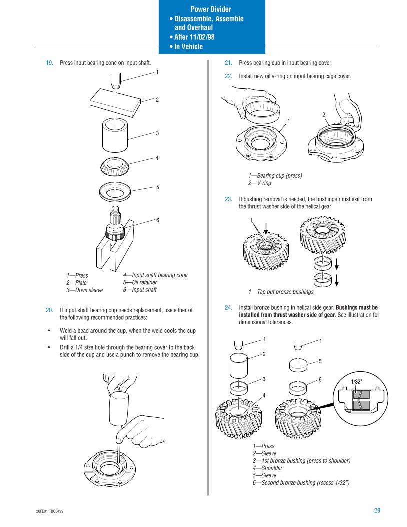
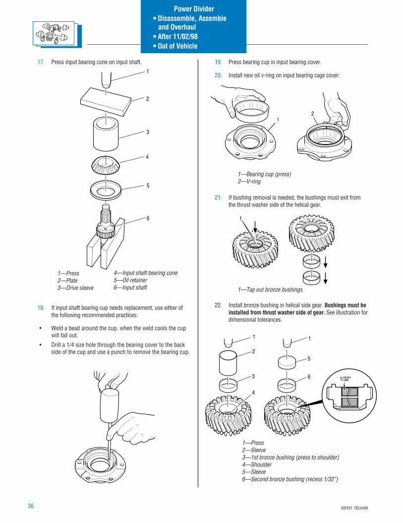
19. Press input bearing cone on input shaft.
20. If input shaft bearing cup needs replacement, use either ofthe following recommended practices:
• Weld a bead around the cup, when the weld cools the cupwill fall out.
• Drill a 1/4 size hole through the bearing cover to the backside of the cup and use a punch to remove the bearing cup.
12
1—Bearing cup (press)2—V-ring
1
1—Tap out bronze bushings
5
3
2
1
6
4
1—Press2—Plate3—Drive sleeve
4—Input shaft bearing cone5—Oil retainer6—Input shaft
21. Press bearing cup in input bearing cover.
22. Install new oil v-ring on input bearing cage cover.
23. If bushing removal is needed, the bushings must exit fromthe thrust washer side of the helical gear.
24. Install bronze bushing in helical side gear. Bushings must beinstalled from thrust washer side of gear. See illustration fordimensional tolerances.
3
1
2
4
6
1
5
1/32"
1—Press2—Sleeve3—1st bronze bushing (press to shoulder)4—Shoulder5—Sleeve6—Second bronze bushing (recess 1/32”)
Power Divider• Disassemble, Assemble and Overhaul• After 11/02/98• In Vehicle

30 20FE01 TBC5499
Install Lube Pump
1. Install lube pump assembly onto output side gear.
NOTE: The lube pump assembly is a slip-fit on the output shaft sidegear, behind the press fit of the output shaft side gear bearing. Theoutput shaft side gear bearing cone positions the pump assemblyinto the carrier.
2. Install bearing cone on output side gear.
3. Press bearing using proper tools until fully seated.
4. Reinstall output side gear pump and bearing assembly intocarrier.
5. Tighten lube pump retaining screws to 17-21 ft. lbs.(23-38 N•m).
TIP: The lube pump assembly is orientated in such a way that thethree mounting/locating tabs will only line up one way.
NOTE: The lube pump is driven off the IAD assembly through a drivecoupling. The drive coupling has drive tangs to both the IADassembly and the lube pump. The IAD has notches that will acceptthe drive coupling on either face.
6. Install pump drive coupling.
NOTE: If reusing the IAD assembly, install in same direction asremoved.
7. Reinstall IAD.
CAUTION: Exercise care to direct compressed air into asafe area. Wear safety glasses.
Remove Lube Pump
1. Remove inter-axle differential (IAD) and pump collar.
TIP: The output shaft side gear and pump will be removed as anassembly. The lube pump assembly is located on the back side of theoutput shaft side gear, between the output shaft side gear andbearing cone.
NOTE: If the IAD assembly is to be reused, install in same direction asremoved.
2. Remove the three pump retaining screws and remove thepump and output shaft side gear as an assembly.
3. Inspect the lube pump if metal particles are found in axleassembly.
4. Remove the magnetic strainer from the carrier and inspectfor wear material in the same manner as the drain plug.Wash the magnetic strainer in solvent and blow dry withcompressed air to remove oil and metal particles.
NOTE: The pump assembly must turn freely by hand. The pump isnon-serviceable and must be replaced as a complete assembly.
1
1—Magnetic strainer
Power Divider
• Remove and Install• Lube Pump
3120FE01 TBC5499
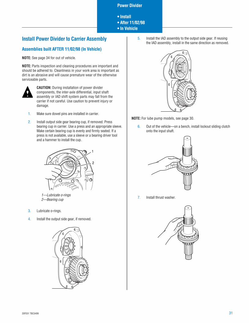
Install Power Divider to Carrier Assembly
Assemblies built AFTER 11/02/98 (In Vehicle)
NOTE: See page 34 for out of vehicle.
NOTE: Parts inspection and cleaning procedures are important andshould be adhered to. Cleanliness in your work area is important asdirt is an abrasive and will cause premature wear of the otherwiseserviceable parts.
CAUTION: During installation of power dividercomponents, the inter-axle differential, input shaftassembly or IAD shift system parts may fall from thecarrier if not careful. Use caution to prevent injury ordamage.
1. Make sure dowel pins are installed in carrier.
2. Install output side gear bearing cup, if removed. Pressbearing cup in carrier. Use a press and an appropriate sleeve.Make certain bearing cup is evenly and firmly seated. If apress is not available, use a sleeve or a bearing driver tooland a hammer to install the cup.
3. Lubricate o-rings.
4. Install the output side gear, if removed.
1
2
1—Lubricate o-rings2—Bearing cup
5. Install the IAD assembly to the output side gear. If reusingthe IAD assembly, install in the same direction as removed.
NOTE: For lube pump models, see page 30.
6. Out of the vehicle—on a bench, install lockout sliding clutchonto the input shaft.
7. Install thrust washer.
Power Divider
• Install• After 11/02/98• In Vehicle
32 20FE01 TBC5499
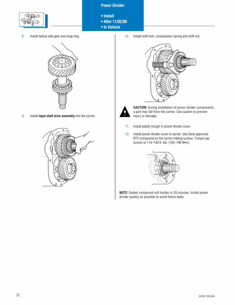
11. Install plastic trough in power divider cover.
12. Install power divider cover to carrier. Use Dana approvedRTV compound on the carrier mating surface. Torque capscrews to 114–140 ft. lbs. (155–190 N•m).
NOTE: Gasket compound will harden in 20 minutes. Install powerdivider quickly as possible to avoid future leaks.
8. Install helical side gear and snap ring.
9. Install input shaft drive assembly into the carrier.
10. Install shift fork, compression spring and shift rod.
CAUTION: During installation of power divider components,a part may fall from the carrier. Use caution to preventinjury or damage.
Power Divider
• Install• After 11/02/98• In Vehicle
3320FE01 TBC5499
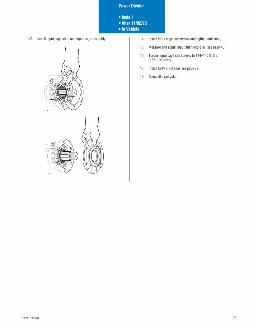
14. Install input cage cap screws and tighten until snug.
15. Measure and adjust input shaft end-play, see page 40.
16. Torque input cage cap screws to 114–140 ft. lbs.(155–190 N•m).
17. Install NEW input seal, see page 72.
18. Reinstall input yoke.
13. Install input cage shim and input cage assembly.
Power Divider
• Install• After 11/02/98• In Vehicle
34 20FE01 TBC5499
Disassemble, Assemble and OverhaulPower Divider
Assemblies built AFTER 11/02/98 – Out of Vehicle
The power divider cover comes off as a unit followed by the inputshaft and then the helical side gear.
The power divider can be replaced with the axle assembly both in orout of the chassis and with the differential carrier assembled to theaxle housing.
CAUTION: During removal of power divider cover, theinter-axle differential (IAD), input shaft assembly or IADshift system parts may fall from the carrier if not careful.Use caution to prevent injury or damage.
1. Disconnect the main driveline.
2. Disconnect the lockout air line.
3. Remove input yoke.
4. Remove input seal.
5. Position a drain pan under the power divider unit.
6. Remove PDU cap screws.
7. Remove power divider cover.
8. Remove shift fork, compression spring and shift rod.
9. Remove input shaft and helical thrust washer from thecarrier.
10. Remove helical side gear.
Power Divider• Disassemble, Assemble and Overhaul• After 11/02/98• Out of Vehicle
3520FE01 TBC5499
11. Remove the IAD assembly from the output side gear.
12. Remove the output side gear.
NOTE: Remove lube pump if you have one. See page 37.
1—Press2—Bearing3—Oil retainer4—Input shaft
1
2
3
4
13. Inspect output side gear o-rings for nicks and cuts. Replace ifnecessary.
14. Install new bearing cup.
15. Remove input shaft bearing cone and oil retainer, ifnecessary.
16. Press new oil retainer on input shaft.
CAUTION: It is not recommended to reuse the oil retainerdue to possible damage that may occur while removing theinput shaft bearing cone. While pressing on new oilretainer, make sure not to over press, and/or press with theretainer at an angle. If the retainer is bent or distorted itmay rub on the input cage or not seal properly to thev-ring.
Power Divider• Disassemble, Assemble and Overhaul• After 11/02/98• Out of Vehicle
36 20FE01 TBC5499
17. Press input bearing cone on input shaft.
18. If input shaft bearing cup needs replacement, use either ofthe following recommended practices:
• Weld a bead around the cup, when the weld cools the cupwill fall out.
• Drill a 1/4 size hole through the bearing cover to the backside of the cup and use a punch to remove the bearing cup.
12
1—Bearing cup (press)2—V-ring
1
1—Tap out bronze bushings
5
3
2
1
6
4
1—Press2—Plate3—Drive sleeve
4—Input shaft bearing cone5—Oil retainer6—Input shaft
3
1
2
4
6
1
5
1/32"
1—Press2—Sleeve3—1st bronze bushing (press to shoulder)4—Shoulder5—Sleeve6—Second bronze bushing (recess 1/32”)
19. Press bearing cup in input bearing cover.
20. Install new oil v-ring on input bearing cage cover.
21. If bushing removal is needed, the bushings must exit fromthe thrust washer side of the helical gear.
22. Install bronze bushing in helical side gear. Bushings must beinstalled from thrust washer side of gear. See illustration fordimensional tolerances.
Power Divider• Disassemble, Assemble and Overhaul• After 11/02/98• Out of Vehicle
3720FE01 TBC5499
Install Lube Pump
1. Install lube pump assembly onto output side gear.
NOTE: The lube pump assembly is a slip-fit on the output shaft sidegear, behind the press fit of the output shaft side gear bearing. Theoutput shaft side gear bearing cone positions the pump assemblyinto the carrier.
2. Install bearing cone on output side gear.
3. Press bearing using proper tools until fully seated.
4. Reinstall output side gear pump and bearing assembly intocarrier.
5. Tighten lube pump retaining screws to 17-21 ft. lbs.(23-38 N•m).
TIP: The lube pump assembly is orientated in such a way that thethree mounting/locating tabs will only line up one way.
NOTE: The lube pump is driven off the IAD assembly through a drivecoupling. The drive coupling has drive tangs to both the IADassembly and the lube pump. The IAD has notches that will acceptthe drive coupling on either face.
6. Install pump drive coupling.
NOTE: If reusing the IAD assembly, install in same direction asremoved.
7. Reinstall IAD.
CAUTION: Exercise care to direct compressed air into asafe area. Wear safety glasses.
Remove Lube Pump
1. Remove inter-axle differential (IAD) and pump collar.
TIP: The output shaft side gear and pump will be removed as anassembly. The lube pump assembly is located on the back side of theoutput shaft side gear, between the output shaft side gear andbearing cone.
NOTE: If the IAD assembly is to be reused, install in same direction asremoved.
2. Remove the three pump retaining screws and remove thepump and output shaft side gear as an assembly.
3. Inspect the lube pump if metal particles are found in axleassembly.
4. Remove the magnetic strainer from the carrier and inspectfor wear material in the same manner as the drain plug.Wash the magnetic strainer in solvent and blow dry withcompressed air to remove oil and metal particles.
NOTE: The pump assembly must turn freely by hand. The pump isnon-serviceable and must be replaced as a complete assembly.
1
1—Magnetic strainer
Power Divider
• Remove and Install• Lube Pump
38 20FE01 TBC5499
Install Power Divider to Carrier Assembly
Assemblies built AFTER 11/02/98 (Out of Vehicle)
NOTE: Parts inspection and cleaning procedures are important andshould be adhered to. Cleanliness in your work area is important asdirt is an abrasive and will cause premature wear of the otherwiseserviceable parts.
NOTE: It is assumed that the different carrier is secured in a stand.
CAUTION: During installation of power divider components,parts may fall from the carrier if not careful. Use caution toprevent injury or damage.
1. Make sure dowel pins are installed in carrier.
2. Output side gear bearing cup. If removed, press bearing cupin carrier. Use a press and an appropriate sleeve. Makecertain bearing cup is evenly and firmly seated. If a press isnot available, use a sleeve or a bearing driver tool and ahammer to install the cup.
3. Lubricate o-rings.
4. Install the output side gear using one of the followinginstructions (non-pump models or lube pump models).
Non-pump Models
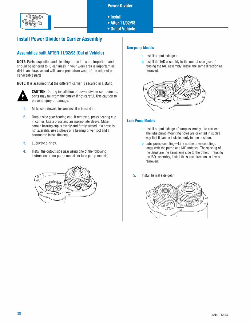
a. Install output side gear.
b. Install the IAD assembly to the output side gear. Ifreusing the IAD assembly, install the same direction asremoved.
Lube Pump Models
a. Install output side gear/pump assembly into carrier.The lube pump mounting holes are oriented in such away that it can be installed only in one position.
b. Lube pump coupling—Line up the drive couplingstangs with the pump and IAD notches. The spacing ofthe tangs are the same, one side to the other. If reusingthe IAD assembly, install the same direction as it wasremoved.
5. Install helical side gear.
Power Divider
• Install• After 11/02/98• Out of Vehicle
3920FE01 TBC5499
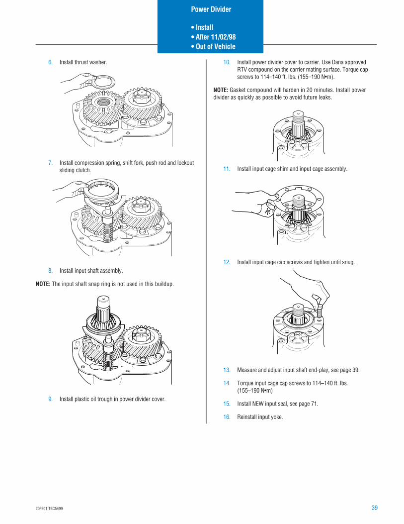
6. Install thrust washer.
7. Install compression spring, shift fork, push rod and lockoutsliding clutch.
8. Install input shaft assembly.
NOTE: The input shaft snap ring is not used in this buildup.
9. Install plastic oil trough in power divider cover.
10. Install power divider cover to carrier. Use Dana approvedRTV compound on the carrier mating surface. Torque capscrews to 114–140 ft. lbs. (155–190 N•m).
NOTE: Gasket compound will harden in 20 minutes. Install powerdivider as quickly as possible to avoid future leaks.
11. Install input cage shim and input cage assembly.
12. Install input cage cap screws and tighten until snug.
13. Measure and adjust input shaft end-play, see page 39.
14. Torque input cage cap screws to 114–140 ft. lbs.(155–190 N•m)
15. Install NEW input seal, see page 71.
16. Reinstall input yoke.
Power Divider
• Install• After 11/02/98• Out of Vehicle
40 20FE01 TBC5499
Measure and Adjust Input Shaft End-Play
NOTE: After power divider overhaul and installation on carrier, checkand adjust input shaft end-play.
The correct end-play when new parts are used in overhaul is .0.003”to 0.007”, with reused parts the maximum is 0.14”.
1. Remove input shaft nut. Remove input bearing cover capscrews. Remove bearing cover (and shim pack if installed).
2. Reinstall bearing cover without shims. Hold in position withhand pressure and measure clearance between power dividercover and bearing cover, using a feeler gauge.
3. The bearing cover clearance measured in Step 2 plus 0.005”will equal shim pack thickness required for desired end-play(rebuild with new parts). Add 0.015” to shim pack for rebuildwith used parts.
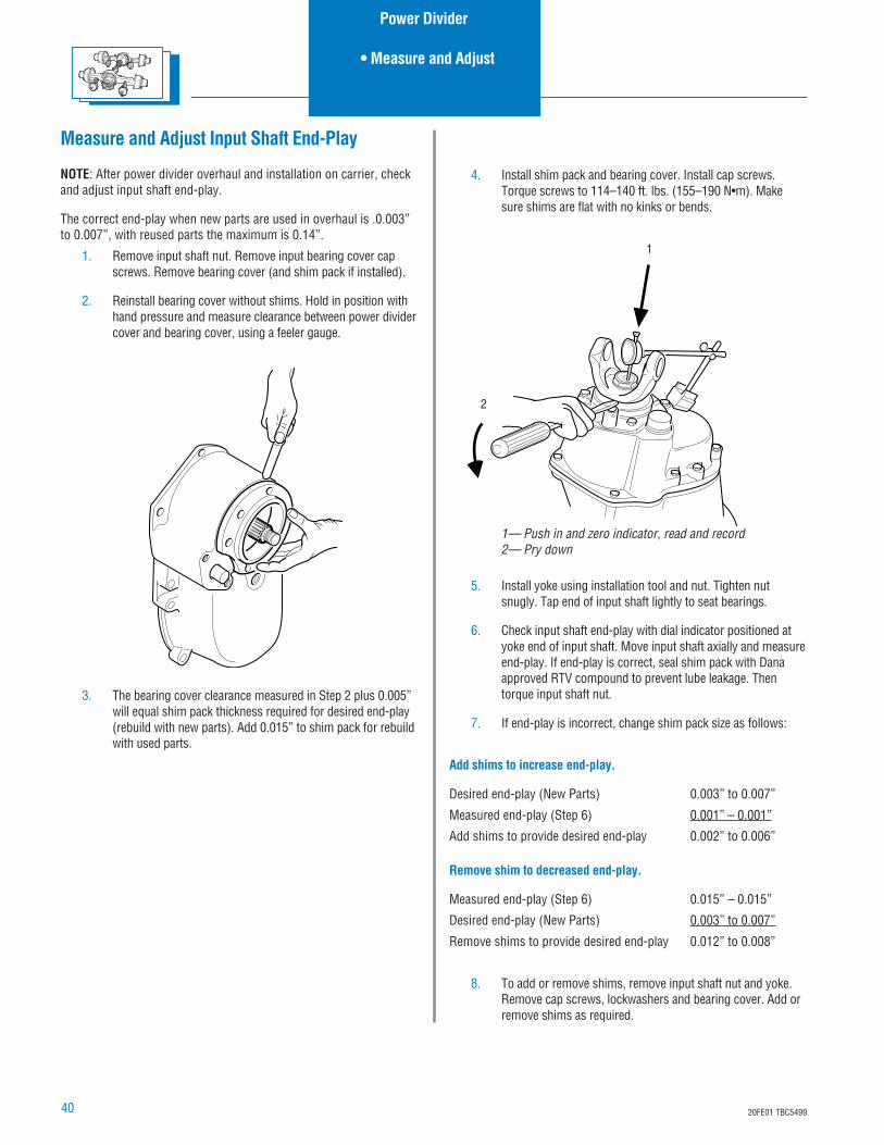
4. Install shim pack and bearing cover. Install cap screws.Torque screws to 114–140 ft. lbs. (155–190 N•m). Makesure shims are flat with no kinks or bends.
5. Install yoke using installation tool and nut. Tighten nutsnugly. Tap end of input shaft lightly to seat bearings.
6. Check input shaft end-play with dial indicator positioned atyoke end of input shaft. Move input shaft axially and measureend-play. If end-play is correct, seal shim pack with Danaapproved RTV compound to prevent lube leakage. Thentorque input shaft nut.
7. If end-play is incorrect, change shim pack size as follows:
Add shims to increase end-play.
Desired end-play (New Parts) 0.003” to 0.007”
Measured end-play (Step 6) 0.001” – 0.001”
Add shims to provide desired end-play 0.002” to 0.006”
Remove shim to decreased end-play.
Measured end-play (Step 6) 0.015” – 0.015”
Desired end-play (New Parts) 0.003” to 0.007”
Remove shims to provide desired end-play 0.012” to 0.008”
8. To add or remove shims, remove input shaft nut and yoke.Remove cap screws, lockwashers and bearing cover. Add orremove shims as required.
1
2
1— Push in and zero indicator, read and record2— Pry down
Power Divider
• Measure and Adjust
4120FE01 TBC5499
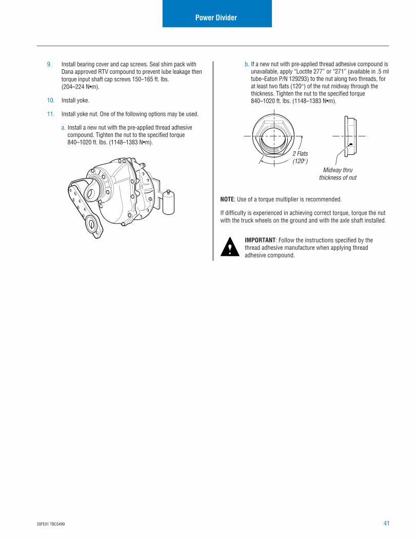
9. Install bearing cover and cap screws. Seal shim pack withDana approved RTV compound to prevent lube leakage thentorque input shaft cap screws 150–165 ft. lbs.(204–224 N•m).
10. Install yoke.
11. Install yoke nut. One of the following options may be used.
a. Install a new nut with the pre-applied thread adhesivecompound. Tighten the nut to the specified torque840–1020 ft. lbs. (1148–1383 N•m).
Power Divider
2 Flats(120°)
Midway thruthickness of nut
b. If a new nut with pre-applied thread adhesive compound isunavailable, apply “Loctite 277” or “271” (available in .5 mltube–Eaton P/N 129293) to the nut along two threads, forat least two flats (120°) of the nut midway through thethickness. Tighten the nut to the specified torque840–1020 ft. lbs. (1148–1383 N•m).
NOTE: Use of a torque multiplier is recommended.
If difficulty is experienced in achieving correct torque, torque the nutwith the truck wheels on the ground and with the axle shaft installed.
IMPORTANT: Follow the instructions specified by thethread adhesive manufacture when applying threadadhesive compound.
42 20FE01 TBC5499
Disassemble Carrier Assembly (All Forward and Rear Axles)
NOTE: For models having the wheel differential lock option or acarrier thrust bolt follow the steps below. These parts must beremoved first before further removal of the wheel differential cantake place.
Remove Wheel Differential – Models with WheelDifferential Lock
1. For ease of servicing, mount differential carrier in stand withdifferential lock facing up.
NOTE: To overhaul and reassemble the wheel differential, the shiftfork and clutch assembly must be removed from carrier. Seeinstructions below.
2. Remove shift cylinder mounting screws, then lift shiftcylinder, piston and o-ring assembly off carrier and end ofpush rod.
3. To disassemble shift cylinder for inspection, first remove orback off actuator switch. The piston and o-ring assembly canbe removed by inserting a pencil-size tool through thecylinder air port.
4. Grasp push rod end and pull it out of the shift fork, springand carrier.
Carrier Assembly
1
1—Shift cylinder
12
10
11
9
13
8
7
6
5
3
12
414
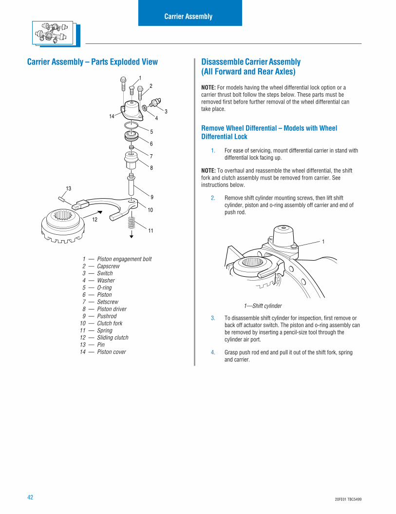
1 — Piston engagement bolt2 — Capscrew3 — Switch4 — Washer5 — O-ring6 — Piston7 — Setscrew8 — Piston driver9 — Pushrod
10 — Clutch fork11 — Spring12 — Sliding clutch13 — Pin14 — Piston cover
Carrier Assembly – Parts Exploded View
4320FE01 TBC5499
NOTE: When the push rod is disengaged from the shift fork, the forkand sliding curvic clutch assembly can be removed from carrier.
NOTE: Do not disassemble shift fork from the sliding curvic clutchunless parts replacement is necessary. To disassemble, use pinpunch to remove spring pin from long leg of fork. The fork can nowbe disengaged from the clutch.
5. Remove the snap ring, then lift fixed curvic clutch offdifferential case hub spline. Further disassembly of carrier isthe same for axles without differential lock.
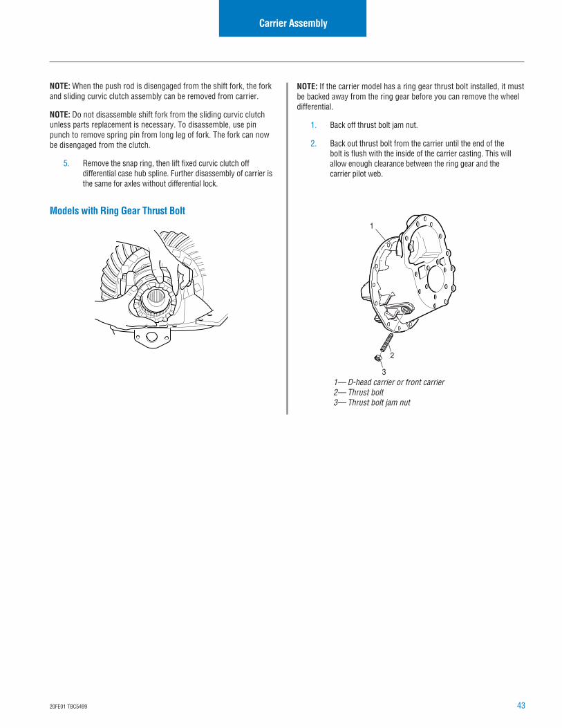
Models with Ring Gear Thrust Bolt1
3
2
NOTE: If the carrier model has a ring gear thrust bolt installed, it mustbe backed away from the ring gear before you can remove the wheeldifferential.
1. Back off thrust bolt jam nut.
2. Back out thrust bolt from the carrier until the end of thebolt is flush with the inside of the carrier casting. This willallow enough clearance between the ring gear and thecarrier pilot web.
Carrier Assembly
1— D-head carrier or front carrier2— Thrust bolt3— Thrust bolt jam nut
44 20FE01 TBC5499
Carrier Assembly
Remove Wheel Differential (All Standard Models)
NOTE: Omit this step if the gear set is to be replaced. If gear set is tobe reused, check tooth contact pattern and ring gear backlash beforedisassembling differential carrier. When checking backlash, a yoke orhelical gear must be installed and torqued to get an accurate reading.Best results are obtained when established wear patterns aremaintained in used gearing.
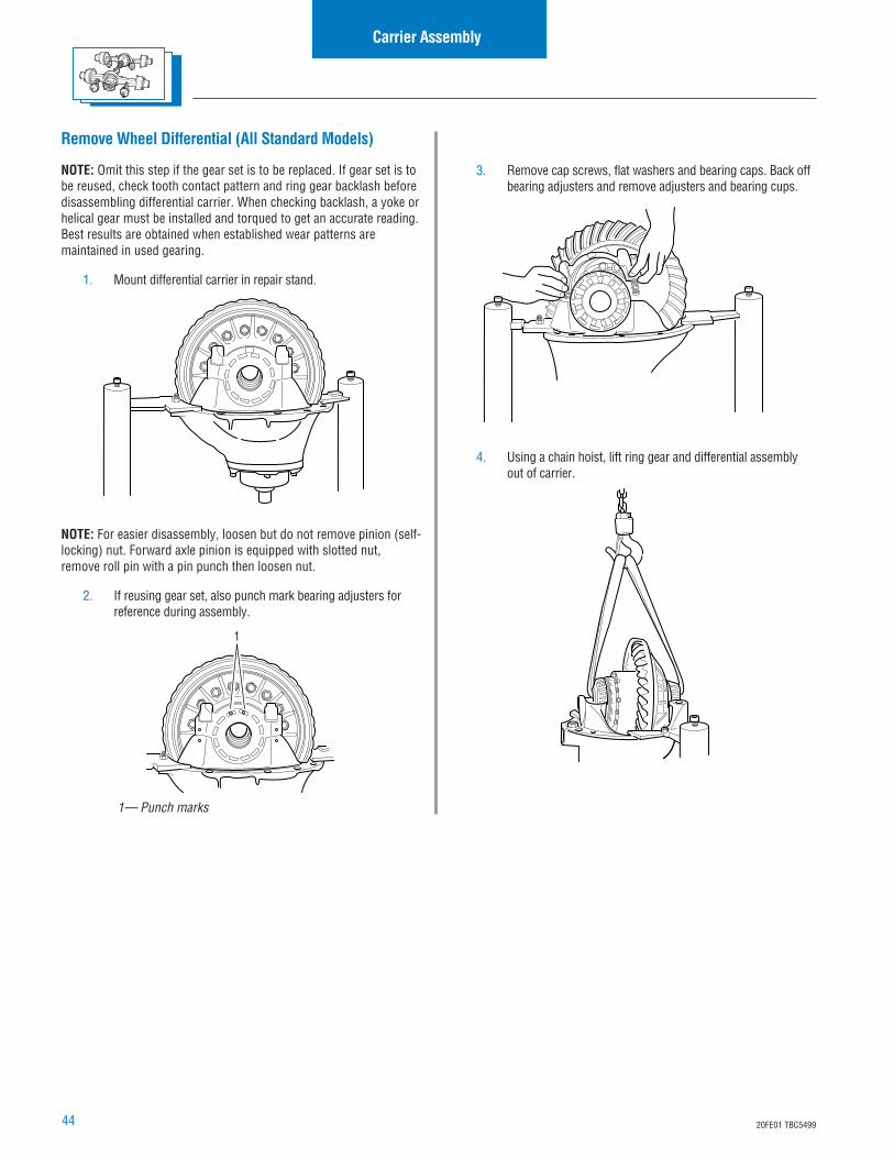
1. Mount differential carrier in repair stand.
NOTE: For easier disassembly, loosen but do not remove pinion (self-locking) nut. Forward axle pinion is equipped with slotted nut,remove roll pin with a pin punch then loosen nut.
2. If reusing gear set, also punch mark bearing adjusters forreference during assembly.
1— Punch marks
1
3. Remove cap screws, flat washers and bearing caps. Back offbearing adjusters and remove adjusters and bearing cups.
4. Using a chain hoist, lift ring gear and differential assemblyout of carrier.
4520FE01 TBC5499
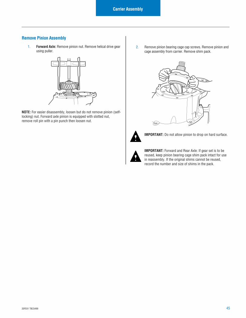
Remove Pinion Assembly
1. Forward Axle: Remove pinion nut. Remove helical drive gearusing puller.
NOTE: For easier disassembly, loosen but do not remove pinion (self-locking) nut. Forward axle pinion is equipped with slotted nut,remove roll pin with a pin punch then loosen nut.
Carrier Assembly
2. Remove pinion bearing cage cap screws. Remove pinion andcage assembly from carrier. Remove shim pack.
IMPORTANT: Do not allow pinion to drop on hard surface.
IMPORTANT: Forward and Rear Axle: If gear set is to bereused, keep pinion bearing cage shim pack intact for usein reassembly. If the original shims cannot be reused,record the number and size of shims in the pack.
46 20FE01 TBC5499
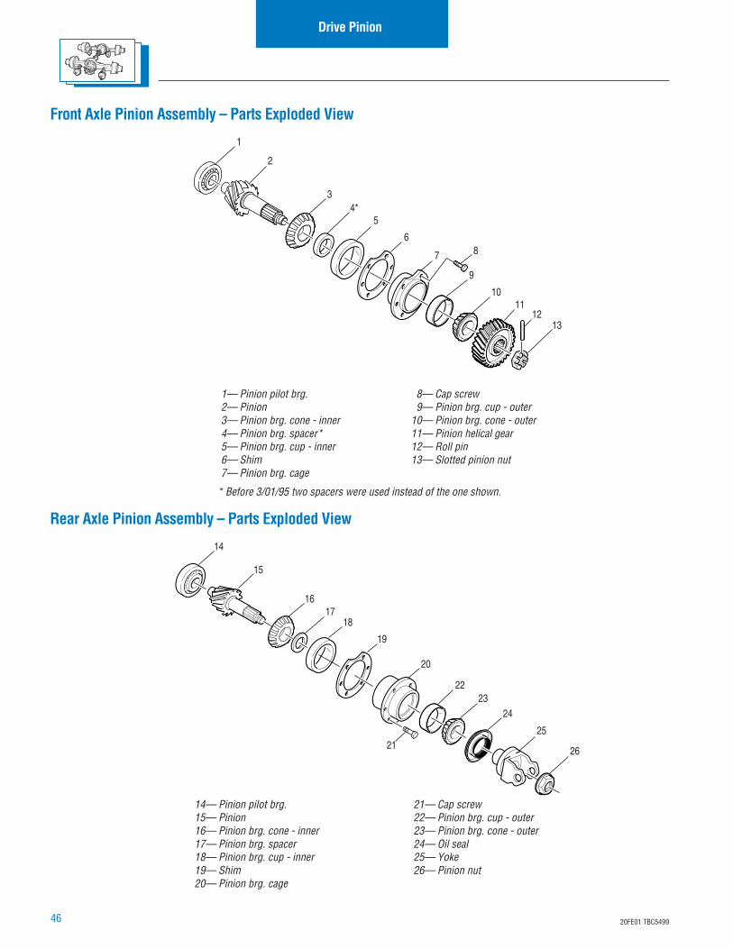
Drive Pinion
1— Pinion pilot brg.2— Pinion3— Pinion brg. cone - inner4— Pinion brg. spacer*5— Pinion brg. cup - inner6— Shim7— Pinion brg. cage
8— Cap screw9— Pinion brg. cup - outer
10— Pinion brg. cone - outer11— Pinion helical gear12— Roll pin13— Slotted pinion nut
Front Axle Pinion Assembly – Parts Exploded View
1
2
34*
5
6
7 8
9
1011
1213
Rear Axle Pinion Assembly – Parts Exploded View
14— Pinion pilot brg.15— Pinion16— Pinion brg. cone - inner17— Pinion brg. spacer18— Pinion brg. cup - inner19— Shim20— Pinion brg. cage
14
15
1617
18
19
20
21
2223
24
25
26
21— Cap screw22— Pinion brg. cup - outer23— Pinion brg. cone - outer24— Oil seal25— Yoke26— Pinion nut
* Before 3/01/95 two spacers were used instead of the one shown.
4720FE01 TBC5499
Drive Pinion
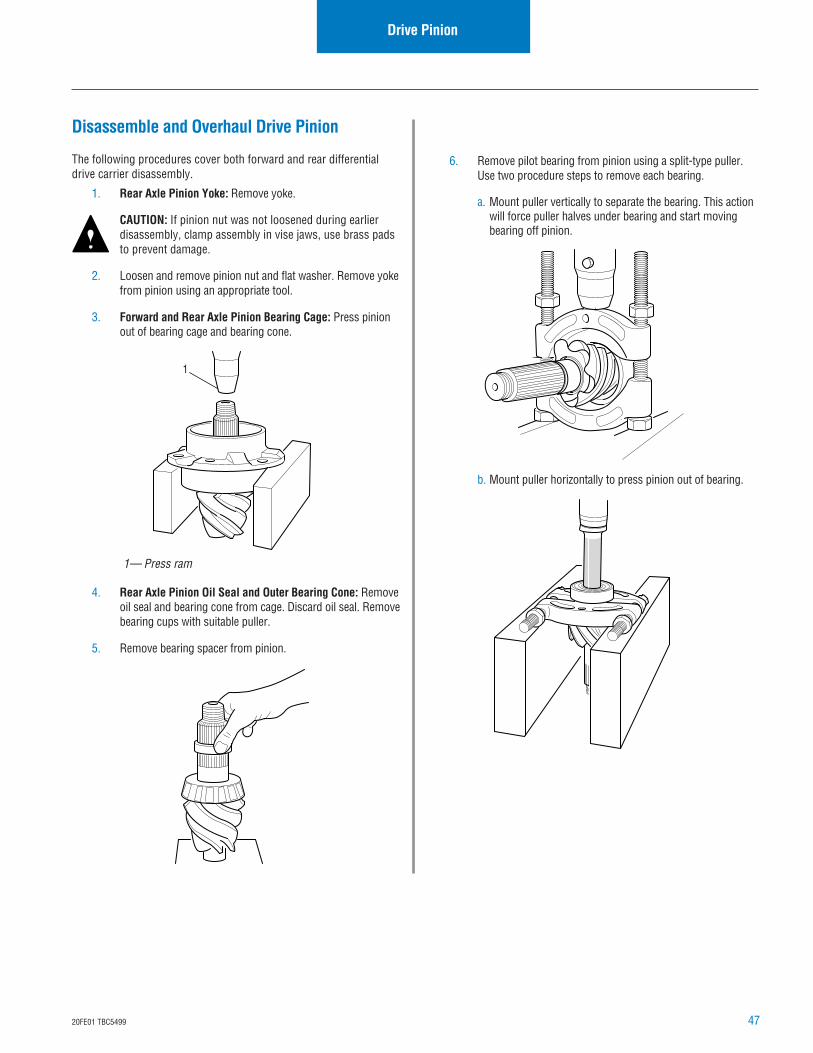
Disassemble and Overhaul Drive Pinion
The following procedures cover both forward and rear differentialdrive carrier disassembly.
1. Rear Axle Pinion Yoke: Remove yoke.
CAUTION: If pinion nut was not loosened during earlierdisassembly, clamp assembly in vise jaws, use brass padsto prevent damage.
2. Loosen and remove pinion nut and flat washer. Remove yokefrom pinion using an appropriate tool.
3. Forward and Rear Axle Pinion Bearing Cage: Press pinionout of bearing cage and bearing cone.
4. Rear Axle Pinion Oil Seal and Outer Bearing Cone: Removeoil seal and bearing cone from cage. Discard oil seal. Removebearing cups with suitable puller.
5. Remove bearing spacer from pinion.
1— Press ram
1
6. Remove pilot bearing from pinion using a split-type puller.Use two procedure steps to remove each bearing.
a. Mount puller vertically to separate the bearing. This actionwill force puller halves under bearing and start movingbearing off pinion.
b. Mount puller horizontally to press pinion out of bearing.
48 20FE01 TBC5499
Drive Pinion
1
1— Press
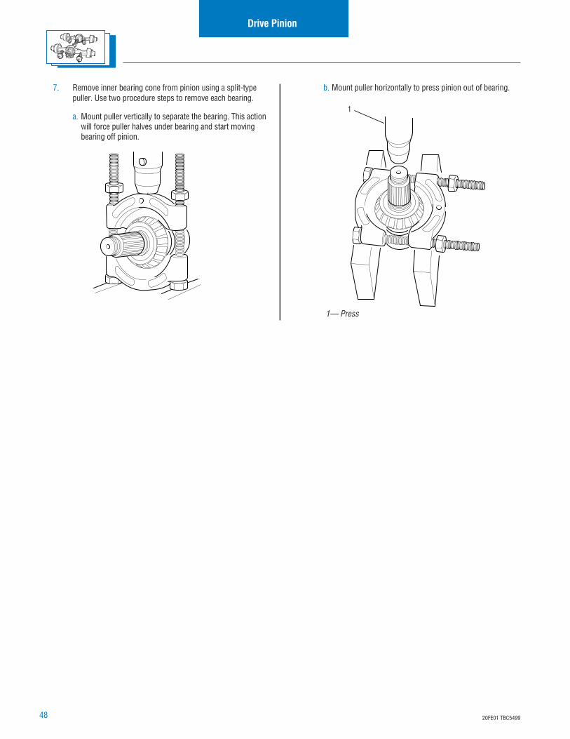
7. Remove inner bearing cone from pinion using a split-typepuller. Use two procedure steps to remove each bearing.
a. Mount puller vertically to separate the bearing. This actionwill force puller halves under bearing and start movingbearing off pinion.
b. Mount puller horizontally to press pinion out of bearing.
4920FE01 TBC5499
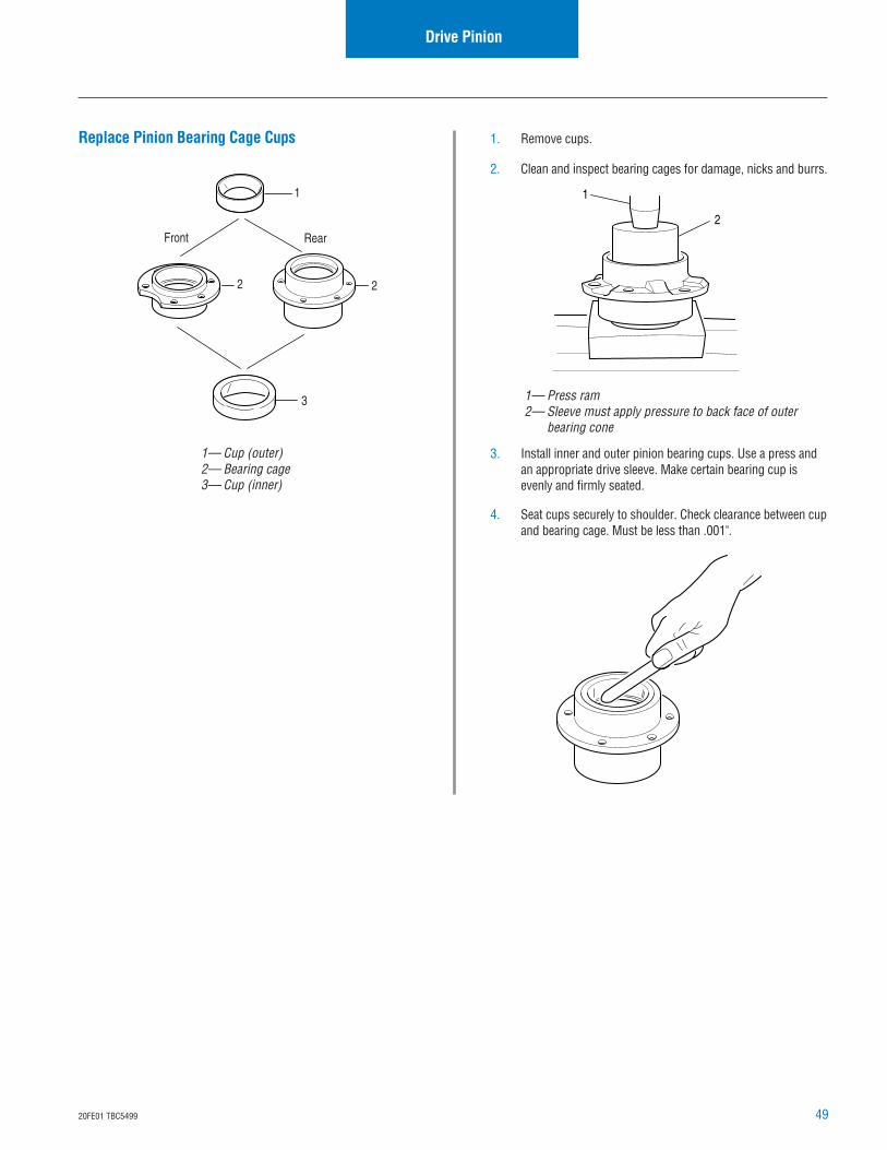
Replace Pinion Bearing Cage Cups
Drive Pinion
1. Remove cups.
2. Clean and inspect bearing cages for damage, nicks and burrs.
3. Install inner and outer pinion bearing cups. Use a press andan appropriate drive sleeve. Make certain bearing cup isevenly and firmly seated.
4. Seat cups securely to shoulder. Check clearance between cupand bearing cage. Must be less than .001".
1
2
1— Press ram2— Sleeve must apply pressure to back face of outer
bearing cone
1— Cup (outer)2— Bearing cage3— Cup (inner)
1
3
22
Front Rear
50 20FE01 TBC5499
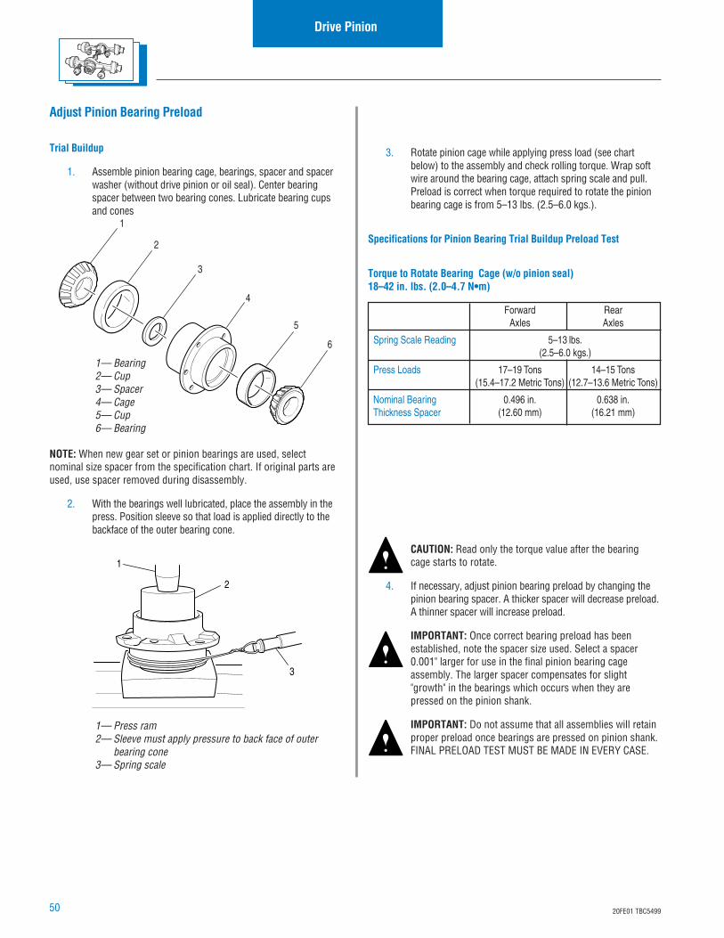
3. Rotate pinion cage while applying press load (see chartbelow) to the assembly and check rolling torque. Wrap softwire around the bearing cage, attach spring scale and pull.Preload is correct when torque required to rotate the pinionbearing cage is from 5–13 lbs. (2.5–6.0 kgs.).
Specifications for Pinion Bearing Trial Buildup Preload Test
Torque to Rotate Bearing Cage (w/o pinion seal)18–42 in. lbs. (2.0–4.7 N•m)
Forward RearAxles Axles
Spring Scale Reading 5–13 lbs.(2.5–6.0 kgs.)
Press Loads 17–19 Tons 14–15 Tons(15.4–17.2 Metric Tons) (12.7–13.6 Metric Tons)
Nominal Bearing 0.496 in. 0.638 in.Thickness Spacer (12.60 mm) (16.21 mm)
CAUTION: Read only the torque value after the bearingcage starts to rotate.
4. If necessary, adjust pinion bearing preload by changing thepinion bearing spacer. A thicker spacer will decrease preload.A thinner spacer will increase preload.
IMPORTANT: Once correct bearing preload has beenestablished, note the spacer size used. Select a spacer0.001" larger for use in the final pinion bearing cageassembly. The larger spacer compensates for slight"growth" in the bearings which occurs when they arepressed on the pinion shank.
IMPORTANT: Do not assume that all assemblies will retainproper preload once bearings are pressed on pinion shank.FINAL PRELOAD TEST MUST BE MADE IN EVERY CASE.
Adjust Pinion Bearing Preload
Trial Buildup
1. Assemble pinion bearing cage, bearings, spacer and spacerwasher (without drive pinion or oil seal). Center bearingspacer between two bearing cones. Lubricate bearing cupsand cones
Drive Pinion
NOTE: When new gear set or pinion bearings are used, selectnominal size spacer from the specification chart. If original parts areused, use spacer removed during disassembly.
2. With the bearings well lubricated, place the assembly in thepress. Position sleeve so that load is applied directly to thebackface of the outer bearing cone.
1— Bearing2— Cup3— Spacer4— Cage5— Cup6— Bearing
1
2
3
4
5
6
1— Press ram2— Sleeve must apply pressure to back face of outer
bearing cone3— Spring scale
3
1
2
5120FE01 TBC5499
Final Buildup
NOTE: On rear axles, do not install oil seal in cage until bearingpreload is correctly adjusted.
IMPORTANT: After bearing cups are installed, preselectpinion bearing spacer using the "trial buildup" procedure.
NOTE: During pinion bearing installation, locate each part in sameposition that was used in "trial buildup" preload test.
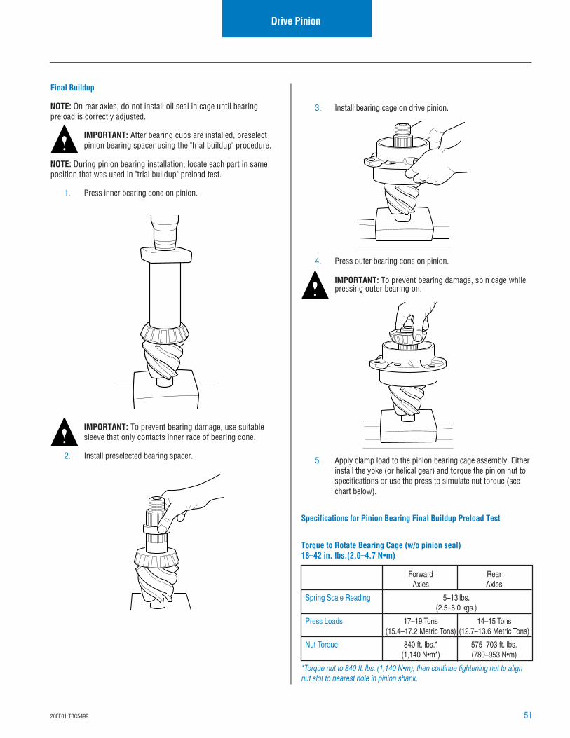
1. Press inner bearing cone on pinion.
IMPORTANT: To prevent bearing damage, use suitablesleeve that only contacts inner race of bearing cone.
2. Install preselected bearing spacer.
Drive Pinion
3. Install bearing cage on drive pinion.
4. Press outer bearing cone on pinion.
IMPORTANT: To prevent bearing damage, spin cage whilepressing outer bearing on.
5. Apply clamp load to the pinion bearing cage assembly. Eitherinstall the yoke (or helical gear) and torque the pinion nut tospecifications or use the press to simulate nut torque (seechart below).
Specifications for Pinion Bearing Final Buildup Preload Test
Torque to Rotate Bearing Cage (w/o pinion seal)18–42 in. lbs.(2.0–4.7 N•m)
Forward RearAxles Axles
Spring Scale Reading 5–13 lbs.(2.5–6.0 kgs.)
Press Loads 17–19 Tons 14–15 Tons(15.4–17.2 Metric Tons) (12.7–13.6 Metric Tons)
Nut Torque 840 ft. lbs.* 575–703 ft. lbs.(1,140 N•m*) (780–953 N•m)
*Torque nut to 840 ft. lbs. (1,140 N•m), then continue tightening nut to alignnut slot to nearest hole in pinion shank.
52 20FE01 TBC5499
Drive Pinion
Vise Method
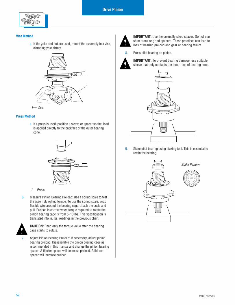
a. If the yoke and nut are used, mount the assembly in a vise,clamping yoke firmly.
Press Method
a. If a press is used, position a sleeve or spacer so that loadis applied directly to the backface of the outer bearingcone.
6. Measure Pinion Bearing Preload: Use a spring scale to testthe assembly rolling torque. To use the spring scale, wrapflexible wire around the bearing cage, attach the scale andpull. Preload is correct when torque required to rotate thepinion bearing cage is from 5–13 lbs. This specification istranslated into in. lbs. readings in the previous chart.
CAUTION: Read only the torque value after the bearingcage starts to rotate.
7. Adjust Pinion Bearing Preload: If necessary, adjust pinionbearing preload. Disassemble the pinion bearing cage asrecommended in this manual and change the pinion bearingspacer. A thicker spacer will decrease preload. A thinnerspacer will increase preload.
1
1— Vise
1
1— Press
Stake Pattern
IMPORTANT: Use the correctly sized spacer. Do not useshim stock or grind spacers. These practices can lead toloss of bearing preload and gear or bearing failure.
8. Press pilot bearing on pinion.
IMPORTANT: To prevent bearing damage, use suitablesleeve that only contacts the inner race of bearing cone.
9. Stake pilot bearing using staking tool. This is essential toretain the bearing.
5320FE01 TBC5499
Adjust Pinion PreloadDrive Pinion
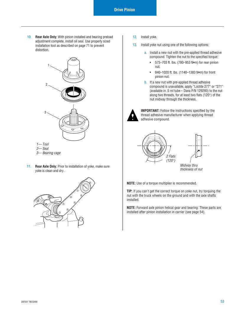
10. Rear Axle Only: With pinion installed and bearing preloadadjustment complete, install oil seal. Use properly sizedinstallation tool as described on page 71 to preventdistortion.
11. Rear Axle Only: Prior to installation of yoke, make sureyoke is clean and dry.
1— Tool2— Seal3— Bearing cage
1
2
3
2 Flats(120°)
Midway thruthickness of nut
12. Install yoke.
13. Install yoke nut using one of the following options:
a. Install a new nut with the pre-applied thread adhesivecompound. Tighten the nut to the specified torque:
• 575–703 ft. lbs. (780–953 N•m) for rear pinionnut.
• 840–1020 ft. lbs. (1140–1383 N•m) for frontpinion nut.
b. If a new nut with pre-applied thread adhesivecompound is unavailable, apply “Loctite 277” or “271”(available in .5 ml tube – Dana P/N 129293) to the nutalong two threads, for at least two flats (120°) of thenut midway through the thickness.
IMPORTANT: Follow the instructions specified by thethread adhesive manufacturer when applying threadadhesive compound.
NOTE: Use of a torque multiplier is recommended.
TIP: If you can't get the correct torque on yoke nut, try torquing thenut with the truck wheels on the ground and with the axle shaftsinstalled.
NOTE: Forward axle pinion helical gear and bearing: These parts areinstalled after pinion installation in carrier (see page 54).
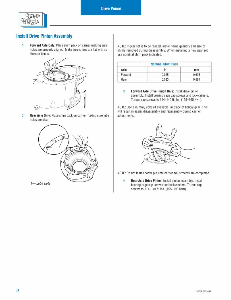
54 20FE01 TBC5499
Drive Pinion
Nominal Shim Pack
Axle in mmForward 0.025 0.635Rear 0.023 0.584
Install Drive Pinion Assembly
1. Forward Axle Only: Place shim pack on carrier making sureholes are properly aligned. Make sure shims are flat with nokinks or bends.
2. Rear Axle Only: Place shim pack on carrier making sure lubeholes are clear.
1— Lube slots
1
NOTE: If gear set is to be reused, install same quantity and size ofshims removed during disassembly. When installing a new gear set,use nominal shim pack indicated.
3. Forward Axle Drive Pinion Only: Install drive pinionassembly. Install bearing cage cap screws and lockwashers.Torque cap screws to 114–140 ft. lbs. (155–190 N•m).
NOTE: Use a dummy yoke (if available) in place of helical gear. Thiswill result in easier disassembly and reassembly during carrieradjustments.
NOTE: Do not install cotter pin until carrier adjustments are completed.
4. Rear Axle Drive Pinion: Install pinion assembly. Installbearing cage cap screws and lockwashers. Torque capscrews to 114–140 ft. lbs. (155–190 N•m).
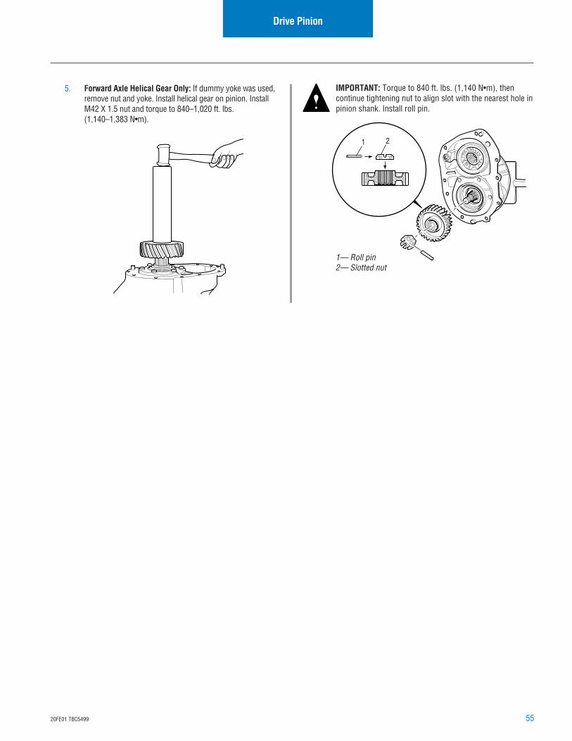
5520FE01 TBC5499
Drive Pinion
5. Forward Axle Helical Gear Only: If dummy yoke was used,remove nut and yoke. Install helical gear on pinion. InstallM42 X 1.5 nut and torque to 840–1,020 ft. lbs.(1,140–1,383 N•m).
IMPORTANT: Torque to 840 ft. lbs. (1,140 N•m), thencontinue tightening nut to align slot with the nearest hole inpinion shank. Install roll pin.
1— Roll pin2— Slotted nut
1 2
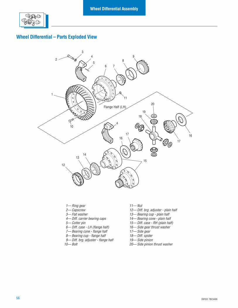
56 20FE01 TBC5499
Wheel Differential Assembly
Flange Half (LH)
1— Ring gear2— Capscrew3— Flat washer4— Diff. carrier bearing caps5— Cotter pin6— Diff. case - LH (flange half)7— Bearing cone - flange half8— Bearing cup - flange half9— Diff. brg. adjuster - flange half
10— Bolt
11— Nut12— Diff. brg. adjuster - plain half13— Bearing cup - plain half14— Bearing cone - plain half15— Diff. case - RH (plain half)16— Side gear thrust washer17— Side gear18— Diff. spider19— Side pinion20— Side pinion thrust washer
2
18
17
16
13
19
4
12
16
15
8
1
10
11
9
76
4
5
3
17
14
20
Wheel Differential – Parts Exploded View
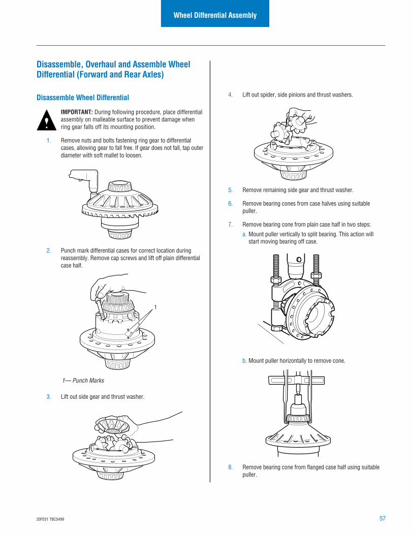
5720FE01 TBC5499
Disassemble, Overhaul and Assemble WheelDifferential (Forward and Rear Axles)
Disassemble Wheel Differential
IMPORTANT: During following procedure, place differentialassembly on malleable surface to prevent damage whenring gear falls off its mounting position.
1. Remove nuts and bolts fastening ring gear to differentialcases, allowing gear to fall free. If gear does not fall, tap outerdiameter with soft mallet to loosen.
2. Punch mark differential cases for correct location duringreassembly. Remove cap screws and lift off plain differentialcase half.
Wheel Differential Assembly
4. Lift out spider, side pinions and thrust washers.
5. Remove remaining side gear and thrust washer.
6. Remove bearing cones from case halves using suitablepuller.
7. Remove bearing cone from plain case half in two steps:
a. Mount puller vertically to split bearing. This action willstart moving bearing off case.
b. Mount puller horizontally to remove cone.
8. Remove bearing cone from flanged case half using suitablepuller.
3. Lift out side gear and thrust washer.
1
1— Punch Marks
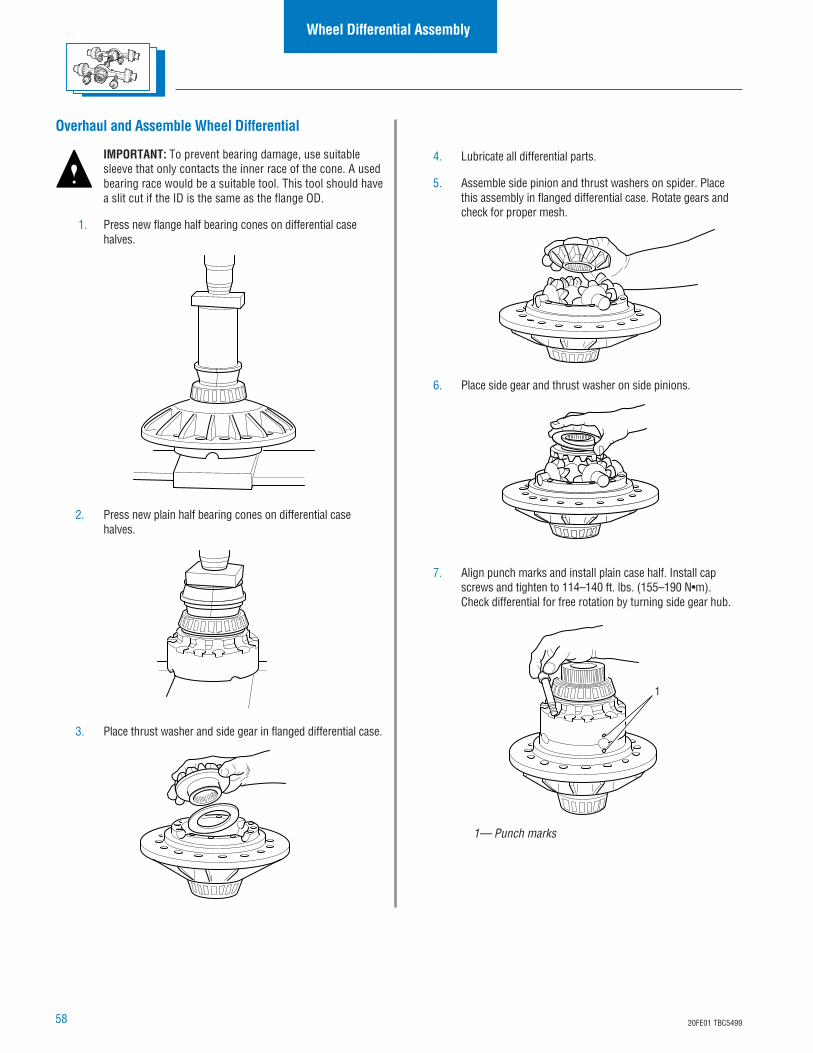
58 20FE01 TBC5499
Wheel Differential Assembly
Overhaul and Assemble Wheel Differential
IMPORTANT: To prevent bearing damage, use suitablesleeve that only contacts the inner race of the cone. A usedbearing race would be a suitable tool. This tool should havea slit cut if the ID is the same as the flange OD.
1. Press new flange half bearing cones on differential casehalves.
2. Press new plain half bearing cones on differential casehalves.
3. Place thrust washer and side gear in flanged differential case.
1— Punch marks
1
4. Lubricate all differential parts.
5. Assemble side pinion and thrust washers on spider. Placethis assembly in flanged differential case. Rotate gears andcheck for proper mesh.
6. Place side gear and thrust washer on side pinions.
7. Align punch marks and install plain case half. Install capscrews and tighten to 114–140 ft. lbs. (155–190 N•m).Check differential for free rotation by turning side gear hub.
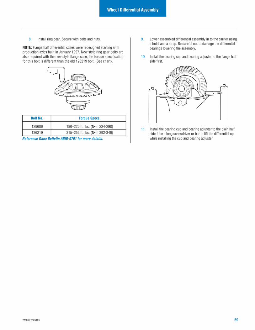
5920FE01 TBC5499
9. Lower assembled differential assembly in to the carrier usinga hoist and a strap. Be careful not to damage the differentialbearings lowering the assembly.
10. Install the bearing cup and bearing adjuster to the flange halfside first.
11. Install the bearing cup and bearing adjuster to the plain halfside. Use a long screwdriver or bar to lift the differential upwhile installing the cup and bearing adjuster.
Wheel Differential Assembly
8. Install ring gear. Secure with bolts and nuts.
NOTE: Flange half differential cases were redesigned starting withproduction axles built in January 1997. New style ring gear bolts arealso required with the new style flange case, the torque specificationfor this bolt is different than the old 126219 bolt. (See chart).
Bolt No. Torque Specs.
129686 180–220 ft. lbs. (N•m 224-298)
126219 215–255 ft. lbs. (N•m 292-346)
Reference Dana Bulletin ABIB-9701 for more details.
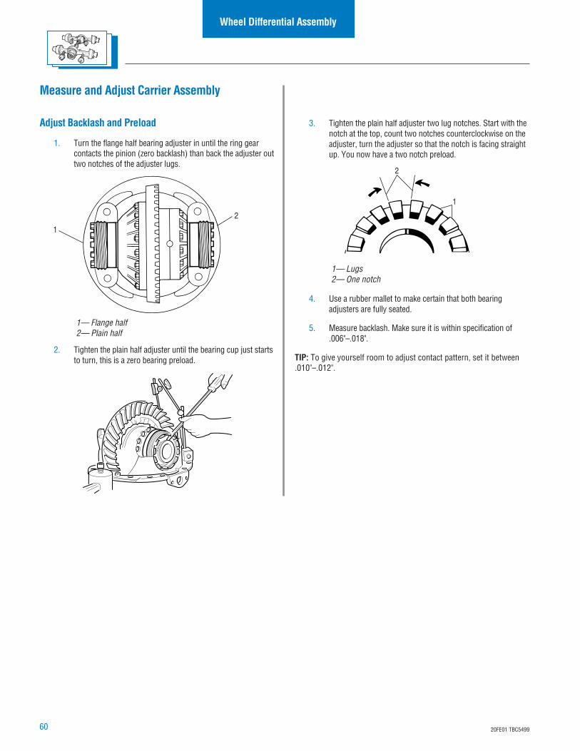
60 20FE01 TBC5499
Wheel Differential Assembly
Measure and Adjust Carrier Assembly
Adjust Backlash and Preload
1. Turn the flange half bearing adjuster in until the ring gearcontacts the pinion (zero backlash) than back the adjuster outtwo notches of the adjuster lugs.
2. Tighten the plain half adjuster until the bearing cup just startsto turn, this is a zero bearing preload.
1— Flange half2— Plain half
1
2
3. Tighten the plain half adjuster two lug notches. Start with thenotch at the top, count two notches counterclockwise on theadjuster, turn the adjuster so that the notch is facing straightup. You now have a two notch preload.
4. Use a rubber mallet to make certain that both bearingadjusters are fully seated.
5. Measure backlash. Make sure it is within specification of.006"–.018".
TIP: To give yourself room to adjust contact pattern, set it between.010"–.012".
1— Lugs2— One notch
1
2
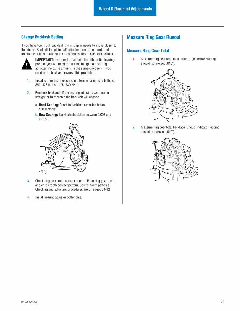
6120FE01 TBC5499
Measure Ring Gear Runout
Measure Ring Gear Total
1. Measure ring gear total radial runout. (Indicator readingshould not exceed .010").
2. Measure ring gear total backface runout (Indicator readingshould not exceed .010").
Change Backlash Setting
If you have too much backlash the ring gear needs to move closer tothe pinion. Back off the plain half adjuster, count the number ofnotches you back it off, each notch equals about .003" of backlash.
IMPORTANT: In order to maintain the differential bearingpreload you will need to turn the flange half bearingadjuster the same amount in the same direction. If youneed more backlash reverse this procedure.
1. Install carrier bearings caps and torque carrier cap bolts to350–428 ft. lbs. (475–580 N•m).
2. Recheck backlash: if the bearing adjusters were not instraight or fully seated the backlash will change.
a. Used Gearing: Reset to backlash recorded beforedisassembly.
b. New Gearing: Backlash should be between 0.006 and0.018".
3. Check ring gear tooth contact pattern. Paint ring gear teethand check tooth contact pattern. Correct tooth patterns.Checking and adjusting procedures are on pages 61-62.
4. Install bearing adjuster cotter pins.
Wheel Differential Adjustments
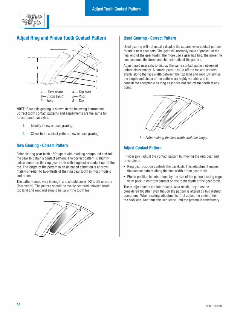
62 20FE01 TBC5499
Adjust Contact Pattern
If necessary, adjust the contact pattern by moving the ring gear anddrive pinion.
• Ring gear position controls the backlash. This adjustment movesthe contact pattern along the face width of the gear tooth.
• Pinion position is determined by the size of the pinion bearing cageshim pack. It controls contact on the tooth depth of the gear tooth.
These adjustments are interrelated. As a result, they must beconsidered together even though the pattern is altered by two distinctoperations. When making adjustments, first adjust the pinion, thenthe backlash. Continue this sequence until the pattern is satisfactory.
Backlash Adjustment
Adjust Tooth Contact Pattern
Adjust Ring and Pinion Tooth Contact Pattern
NOTE: Rear axle gearing is shown in the following instructions.Correct tooth contact patterns and adjustments are the same forforward and rear axles.
1. Identify if new or used gearing.
2. Check tooth contact pattern (new or used gearing).
New Gearing - Correct Pattern
Paint six ring gear teeth 180° apart with marking compound and rollthe gear to obtain a contact pattern. The correct pattern is slightlybelow center on the ring gear tooth with lengthwise contact up off thetoe. The length of the pattern in an unloaded condition is approxi-mately one-half to two-thirds of the ring gear tooth in most modelsand ratios.
The pattern could vary in length and should cover 1/2 tooth or more(face width). The pattern should be evenly centered between toothtop land and root and should be up off the tooth toe.
1
2
3
4
5
61— Face width2— Tooth Depth3— Heel
4— Top land5— Root6— Toe
Used Gearing - Correct Pattern
Used gearing will not usually display the square, even contact patternfound in new gear sets. The gear will normally have a "pocket" at theheal end of the gear tooth. The more use a gear has had, the more theline becomes the dominant characteristic of the pattern.
Adjust used gear sets to display the same contact pattern observedbefore disassembly. A correct pattern is up off the toe and centersevenly along the face width between the top land and root. Otherwise,the length and shape of the pattern are highly variable and isconsidered acceptable as long as it does not run off the tooth at anypoint.
1— Pattern along the face width could be longer.
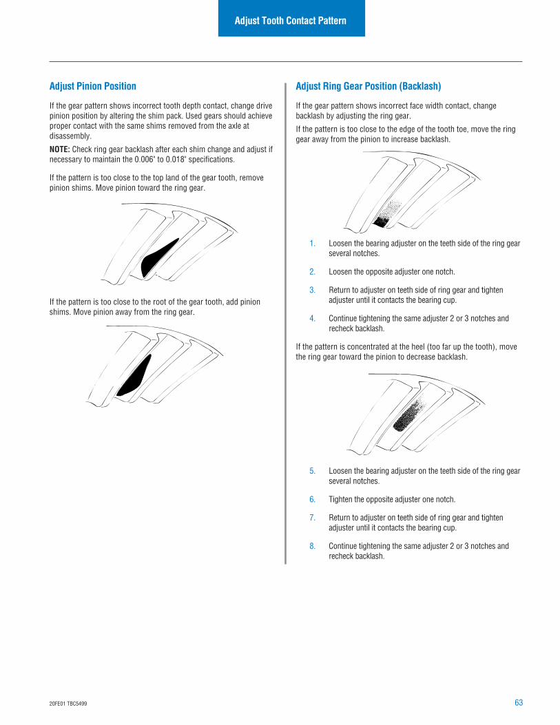
6320FE01 TBC5499
Adjust Tooth Contact Pattern
Adjust Pinion Position
If the gear pattern shows incorrect tooth depth contact, change drivepinion position by altering the shim pack. Used gears should achieveproper contact with the same shims removed from the axle atdisassembly.
NOTE: Check ring gear backlash after each shim change and adjust ifnecessary to maintain the 0.006" to 0.018" specifications.
If the pattern is too close to the top land of the gear tooth, removepinion shims. Move pinion toward the ring gear.
If the pattern is too close to the root of the gear tooth, add pinionshims. Move pinion away from the ring gear.
Adjust Ring Gear Position (Backlash)
If the gear pattern shows incorrect face width contact, changebacklash by adjusting the ring gear.
If the pattern is too close to the edge of the tooth toe, move the ringgear away from the pinion to increase backlash.
1. Loosen the bearing adjuster on the teeth side of the ring gearseveral notches.
2. Loosen the opposite adjuster one notch.
3. Return to adjuster on teeth side of ring gear and tightenadjuster until it contacts the bearing cup.
4. Continue tightening the same adjuster 2 or 3 notches andrecheck backlash.
If the pattern is concentrated at the heel (too far up the tooth), movethe ring gear toward the pinion to decrease backlash.
5. Loosen the bearing adjuster on the teeth side of the ring gearseveral notches.
6. Tighten the opposite adjuster one notch.
7. Return to adjuster on teeth side of ring gear and tightenadjuster until it contacts the bearing cup.
8. Continue tightening the same adjuster 2 or 3 notches andrecheck backlash.
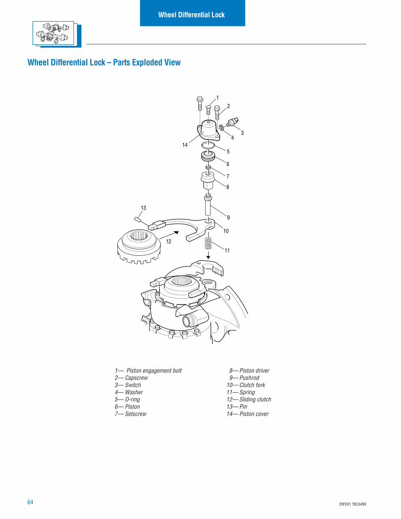
64 20FE01 TBC5499
Wheel Differential Lock – Parts Exploded View
Wheel Differential Lock
12
10
11
9
13
8
7
6
5
3
12
414
1— Piston engagement bolt2— Capscrew3— Switch4— Washer5— O-ring6— Piston7— Setscrew
8— Piston driver9— Pushrod
10— Clutch fork11— Spring12— Sliding clutch13— Pin14— Piston cover
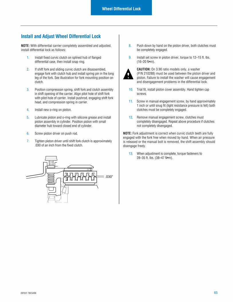
6520FE01 TBC5499
Wheel Differential Lock
Install and Adjust Wheel Differential Lock
NOTE: With differential carrier completely assembled and adjusted,install differential lock as follows:
1. Install fixed curvic clutch on splined hub of flangeddifferential case, then install snap ring.
2. If shift fork and sliding curvic clutch are disassembled,engage fork with clutch hub and install spring pin in the longleg of the fork. See illustration for fork mounting position onclutch.
3. Position compression spring, shift fork and clutch assemblyin shift opening of the carrier. Align pilot hole of shift forkwith pilot hole of carrier. Install pushrod, engaging shift forkhead, and compression spring in carrier.
4. Install new o-ring on piston.
5. Lubricate piston and o-ring with silicone grease and installpiston assembly in cylinder. Position piston with smalldiameter hub toward closed end of cylinder.
6. Screw piston driver on push rod.
7. Tighten piston driver until shift fork clutch is approximately.030 of an inch from the fixed clutch.
8. Push down by hand on the piston driver, both clutches mustbe completely engaged.
9. Install set screw in piston driver, torque to 12–15 ft. lbs.(16–20 N•m).
CAUTION: On 3.90 ratio models only, a washer(P/N 210288) must be used between the piston driver andpiston. Failure to install the washer will cause engagementand disengagement problems in the differential lock.
10. Trial fit, install piston cover assembly. Hand tighten capscrews.
11. Screw in manual engagement screw, by hand approximately1 inch or until snug fit (light resistance pressure is felt) bothclutches must be completely engaged.
12. Remove manual engagement screw, clutches mustcompletely disengaged. Repeat above procedure if clutchesnot completely disengaged.
NOTE: Fork adjustment is correct when curvic clutch teeth are fullyengaged with the fork free when moved by hand. When air pressureis released or the manual bolt is removed, the shift assembly shoulddisengage freely.
13. When adjustment is complete, torque fasteners to28–35 ft. lbs. (38–47 N•m).
.030"
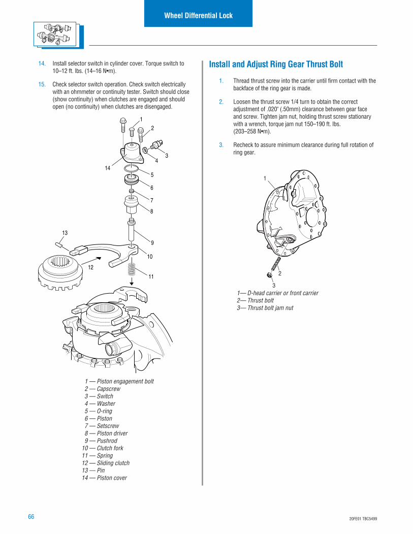
66 20FE01 TBC5499
Install and Adjust Ring Gear Thrust Bolt
1. Thread thrust screw into the carrier until firm contact with thebackface of the ring gear is made.
2. Loosen the thrust screw 1/4 turn to obtain the correctadjustment of .020" (.50mm) clearance between gear faceand screw. Tighten jam nut, holding thrust screw stationarywith a wrench, torque jam nut 150–190 ft. lbs.(203–258 N•m).
3. Recheck to assure minimum clearance during full rotation ofring gear.
Wheel Differential Lock
1
3
2
1— D-head carrier or front carrier2— Thrust bolt3— Thrust bolt jam nut
14. Install selector switch in cylinder cover. Torque switch to10–12 ft. lbs. (14–16 N•m).
15. Check selector switch operation. Check switch electricallywith an ohmmeter or continuity tester. Switch should close(show continuity) when clutches are engaged and shouldopen (no continuity) when clutches are disengaged.
12
10
11
9
13
8
7
6
5
3
12
414
1 — Piston engagement bolt2 — Capscrew3 — Switch4 — Washer5 — O-ring6 — Piston7 — Setscrew8 — Piston driver9 — Pushrod
10 — Clutch fork11 — Spring12 — Sliding clutch13 — Pin14 — Piston cover
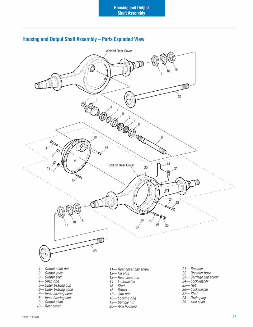
6720FE01 TBC5499
Housing and Output Shaft Assembly – Parts Exploded View
Housing and OutputShaft Assembly
1— Output shaft nut2— Output yoke3— Output seal4— Snap ring5— Outer bearing cup6— Outer bearing cone7— Inner bearing cone8— Inner bearing cup9— Output shaft
10— Rear cover
11— Rear cover cap screw12— Fill plug13— Rear cover nut14— Lockwasher15— Stud16— Dowel17— Jam nut18— Locking ring19— Spindle nut20— Axle housing
21— Breather22— Breather hose23— Carriage cap screw24— Lockwasher25— Nut26— Lockwasher27— Stud28— Drain plug29— Axle shaft
20 2122
2423
2726 25
28
29
29
1718 19
Welded Rear Cover
Bolt on Rear Cover
1718 19
12
10
45
67
8
9
12
3
11
1314
15
16
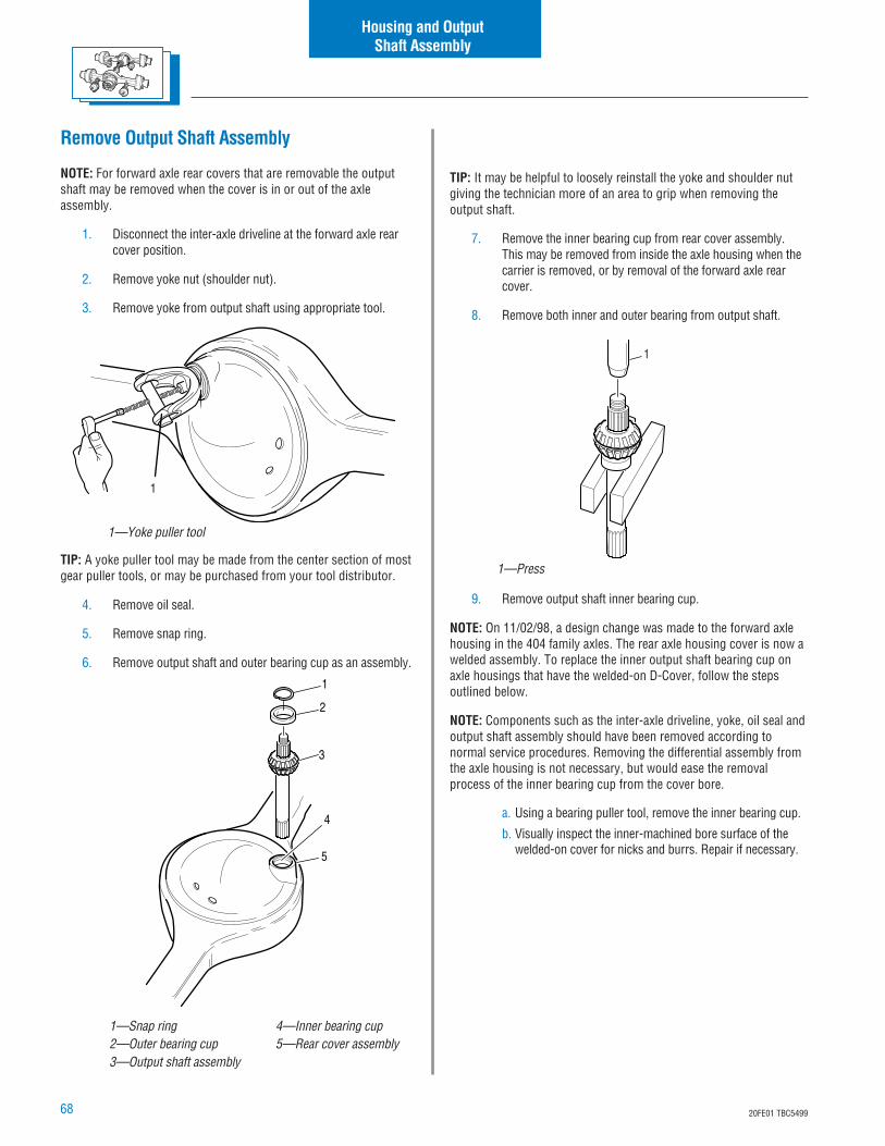
68 20FE01 TBC5499
Remove Output Shaft Assembly
NOTE: For forward axle rear covers that are removable the outputshaft may be removed when the cover is in or out of the axleassembly.
1. Disconnect the inter-axle driveline at the forward axle rearcover position.
2. Remove yoke nut (shoulder nut).
3. Remove yoke from output shaft using appropriate tool.
TIP: A yoke puller tool may be made from the center section of mostgear puller tools, or may be purchased from your tool distributor.
4. Remove oil seal.
5. Remove snap ring.
6. Remove output shaft and outer bearing cup as an assembly.
TIP: It may be helpful to loosely reinstall the yoke and shoulder nutgiving the technician more of an area to grip when removing theoutput shaft.
7. Remove the inner bearing cup from rear cover assembly.This may be removed from inside the axle housing when thecarrier is removed, or by removal of the forward axle rearcover.
8. Remove both inner and outer bearing from output shaft.
9. Remove output shaft inner bearing cup.
NOTE: On 11/02/98, a design change was made to the forward axlehousing in the 404 family axles. The rear axle housing cover is now awelded assembly. To replace the inner output shaft bearing cup onaxle housings that have the welded-on D-Cover, follow the stepsoutlined below.
NOTE: Components such as the inter-axle driveline, yoke, oil seal andoutput shaft assembly should have been removed according tonormal service procedures. Removing the differential assembly fromthe axle housing is not necessary, but would ease the removalprocess of the inner bearing cup from the cover bore.
a. Using a bearing puller tool, remove the inner bearing cup.
b. Visually inspect the inner-machined bore surface of thewelded-on cover for nicks and burrs. Repair if necessary.
Housing and OutputShaft Assembly
1
1—Yoke puller tool
1
1—Press
1—Snap ring2—Outer bearing cup3—Output shaft assembly
4—Inner bearing cup5—Rear cover assembly
2
1
3
4
5
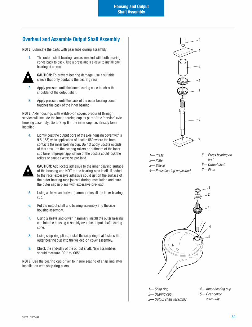
6920FE01 TBC5499
Housing and OutputShaft Assembly
Overhaul and Assemble Output Shaft Assembly
NOTE: Lubricate the parts with gear lube during assembly.
1. The output shaft bearings are assembled with both bearingcones back to back. Use a press and a sleeve to install onebearing at a time.
CAUTION: To prevent bearing damage, use a suitablesleeve that only contacts the bearing race.
2. Apply pressure until the inner bearing cone touches theshoulder of the output shaft.
3. Apply pressure until the back of the outer bearing conetouches the back of the inner bearing.
NOTE: Axle housings with welded-on covers procured throughservice will include the inner bearing cup as part of the "service" axlehousing assembly. Go to Step 6 if the inner cup has already beeninstalled.
4. Lightly coat the output bore of the axle housing cover with a9.5 (.38) wide application of Loctite 680 where the borecontacts the inner bearing cup. Do not apply Loctite outsideof this area—to the bearing rollers or outboard of the innercup bore. Improper application of the Loctite could lock therollers or cause excessive pre-load.
CAUTION: Add loctite adhesive to the inner bearing surfaceof the housing and NOT to the bearing race itself. If addedto the race, excessive adhesive could get on the surface ofthe outer bearing race journal during installation and curethe outer cap in place with excessive pre-load.
5. Using a sleeve and driver (hammer), install the inner bearingcup.
6. Put the output shaft and bearing assembly into the axlehousing assembly.
7. Using a sleeve and driver (hammer), install the outer bearingcup into the housing assembly over the output shaft bearingcone.
8. Using snap ring pliers, install the snap ring that fastens theouter bearing cup into the welded-on cover assembly.
9. Check the end-play of the output shaft. New assembliesshould measure .001" to .005".
NOTE: Use the bearing cup driver to insure seating of snap ring afterinstallation with snap ring pliers.
1— Press2— Plate3— Sleeve4— Press bearing on second
1— Snap ring2— Bearing cup3— Output shaft assembly
3
2
1
4
5
6
7
2
1
3
4
5
5— Press bearing onfirst
6— Output shaft7— Plate
4— Inner bearing cup5— Rear cover
assembly
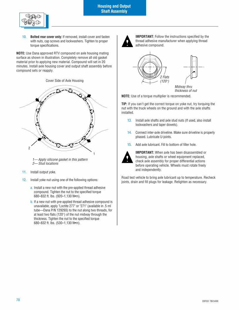
70 20FE01 TBC5499
10. Bolted rear cover only: If removed, install cover and fastenwith nuts, cap screws and lockwashers. Tighten to propertorque specifications.
NOTE: Use Dana approved RTV compound on axle housing matingsurface as shown in illustration. Completely remove all old gasketmaterial prior to applying new material. Compound will set in 20minutes. Install axle housing cover and output shaft assembly beforecompound sets or reapply.
Cover Side of Axle Housing
11. Install output yoke.
12. Install yoke nut using one of the following options:
a. Install a new nut with the pre-applied thread adhesivecompound. Tighten the nut to the specified torque680–832 ft. lbs. (920–1,130 N•m).
b. If a new nut with pre-applied thread adhesive compound isunavailable, apply "Loctite 277" or "271" (available in .5 mltube—Dana P/N 129293) to the nut along two threads, forat least two flats (120°) of the nut midway through thethickness. Tighten the nut to the specified torque680–832 ft. lbs. (530–1,130 N•m).
IMPORTANT: Follow the instructions specified by thethread adhesive manufacturer when applying threadadhesive compound.
NOTE: Use of a torque multiplier is recommended.
TIP: If you can't get the correct torque on yoke nut, try torquing thenut with the truck wheels on the ground and with the axle shaftsinstalled.
13. Install axle shafts and axle stud nuts (If used, also installlockwashers and taper dowels).
14. Connect inter-axle driveline. Make sure driveline is properlyphased. Lubricate U-joints.
15. Add axle lubricant. Fill to bottom of filler hole.
IMPORTANT: When axle has been disassembled orhousing, axle shafts or wheel equipment replaced,check axle assembly for proper differential actionsbefore operating vehicle. Wheels must rotate freelyand independently.
Road test vehicle to bring axle lubricant up to temperature. Recheckjoints, drain and fill plugs for leakage. Retighten as necessary.
Housing and OutputShaft Assembly
1— Apply silicone gasket in this pattern2— Stud locations
1
2
2 Flats(120°)
Midway thruthickness of nut
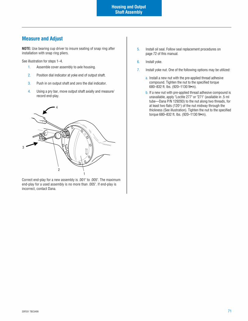
7120FE01 TBC5499
Measure and Adjust
NOTE: Use bearing cup driver to insure seating of snap ring afterinstallation with snap ring pliers.
See illustration for steps 1–4.
1. Assemble cover assembly to axle housing.
2. Position dial indicator at yoke end of output shaft.
3. Push in on output shaft and zero the dial indicator.
4. Using a pry bar, move output shaft axially and measure/record end-play.
Correct end-play for a new assembly is .001" to .005". The maximumend-play for a used assembly is no more than .005". If end-play isincorrect, contact Dana.
Housing and OutputShaft Assembly
21
3
4
5. Install oil seal. Follow seal replacement procedures onpage 72 of this manual.
6. Install yoke.
7. Install yoke nut. One of the following options may be utilized:
a. Install a new nut with the pre-applied thread adhesivecompound. Tighten the nut to the specified torque680–832 ft. lbs. (920–1130 N•m).
b. If a new nut with pre-applied thread adhesive compound isunavailable, apply "Loctite 277" or "271" (available in .5 mltube—Dana P/N 129293) to the nut along two threads, forat least two flats (120°) of the nut midway through thethickness (See illustration). Tighten the nut to the specifiedtorque 680–832 ft. lbs. (920–1130 N•m).
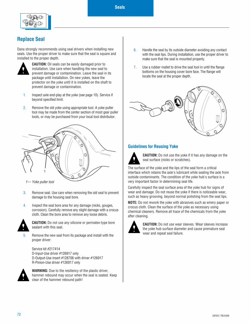
72 20FE01 TBC5499
6. Handle the seal by its outside diameter avoiding any contactwith the seal lips. During installation, use the proper driver tomake sure that the seal is mounted properly.
7. Use a rubber mallet to drive the seal tool in until the flangebottoms on the housing cover bore face. The flange willlocate the seal at the proper depth.
Replace Seal
Dana strongly recommends using seal drivers when installing newseals. Use the proper driver to make sure that the seal is square andinstalled to the proper depth.
CAUTION: Oil seals can be easily damaged prior toinstallation. Use care when handling the new seal toprevent damage or contamination. Leave the seal in itspackage until installation. On new yokes, leave theprotector on the yoke until it is installed on the shaft toprevent damage or contamination.
1. Inspect axle end-play at the yoke (see page 10). Service ifbeyond specified limit.
2. Remove the old yoke using appropriate tool. A yoke pullertool may be made from the center section of most gear pullertools, or may be purchased from your local tool distributor.
3. Remove seal. Use care when removing the old seal to preventdamage to the housing seal bore.
4. Inspect the seal bore area for any damage (nicks, gouges,corrosion). Carefully remove any slight damage with a crocuscloth. Clean the bore area to remove any loose debris.
CAUTION: Do not use any silicone or permatex-type boresealant with this seal.
5. Remove the new seal from its package and install with theproper driver:
Service kit #217414D-Input-Use driver #126917 onlyD-Output-Use insert #128706 with driver #126917R-Pinion-Use driver #126917 only
WARNING: Due to the resiliency of the plastic driver,hammer rebound may occur when the seal is seated. Keepclear of the hammer rebound path!
Seals
1— Yoke puller tool
1
Guidelines for Reusing Yoke
CAUTION: Do not use the yoke if it has any damage on theseal surface (nicks or scratches).
The surface of the yoke and the lips of the seal form a criticalinterface which retains the axle's lubricant while sealing the axle fromoutside contaminants. The condition of the yoke hub's surface is avery important factor in determining seal life.
Carefully inspect the seal surface area of the yoke hub for signs ofwear and damage. Do not reuse the yoke if there is noticeable wear,such as heavy grooving, beyond normal polishing from the seal lips.
NOTE: Do not rework the yoke with abrasives such as emery paper orcrocus cloth. Clean the surface of the yoke as necessary usingchemical cleaners. Remove all trace of the chemicals from the yokeafter cleaning.
CAUTION: Do not use wear sleeves. Wear sleeves increasethe yoke hub surface diameter and cause premature sealwear and repeat seal failure.
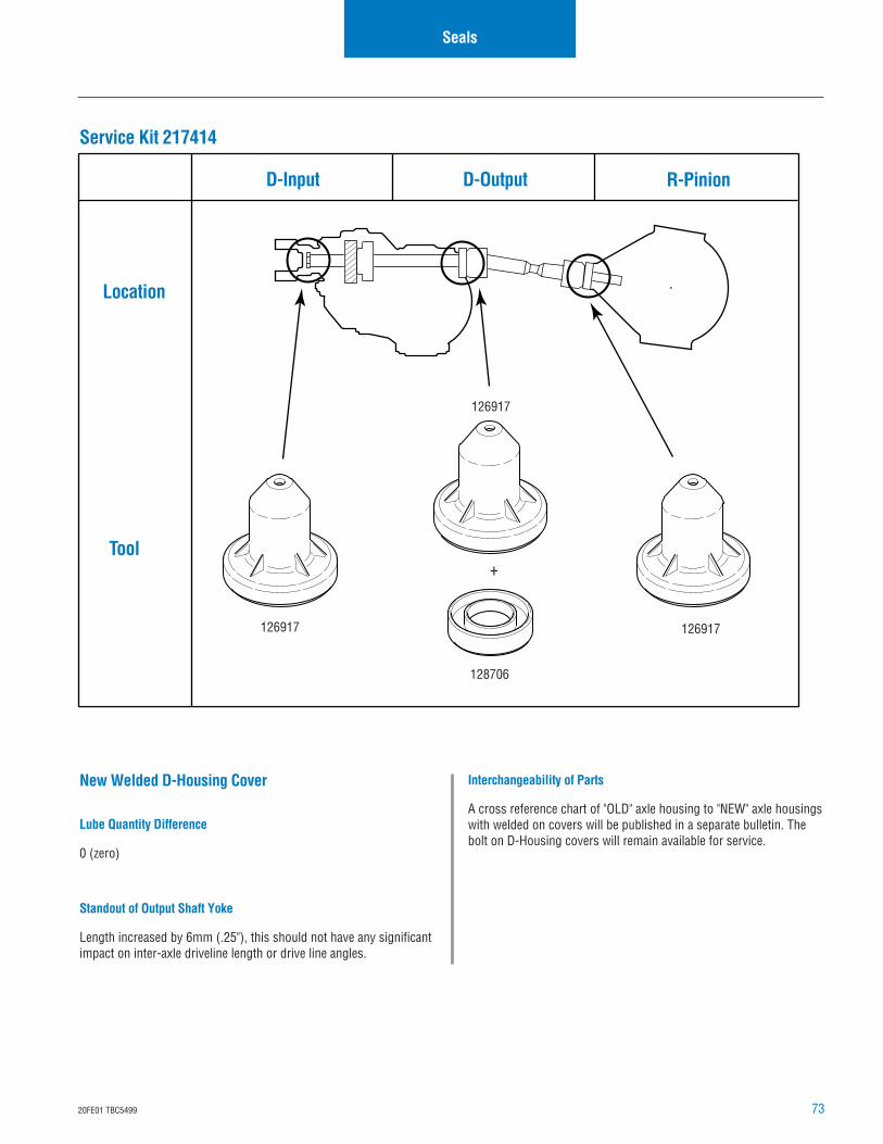
7320FE01 TBC5499
128706
126917
126917 126917
Seals
D-Input D-Output R-Pinion
Location
Tool
Service Kit 217414
New Welded D-Housing Cover
Lube Quantity Difference
0 (zero)
Standout of Output Shaft Yoke
Length increased by 6mm (.25"), this should not have any significantimpact on inter-axle driveline length or drive line angles.
Interchangeability of Parts
A cross reference chart of "OLD" axle housing to "NEW" axle housingswith welded on covers will be published in a separate bulletin. Thebolt on D-Housing covers will remain available for service.
+
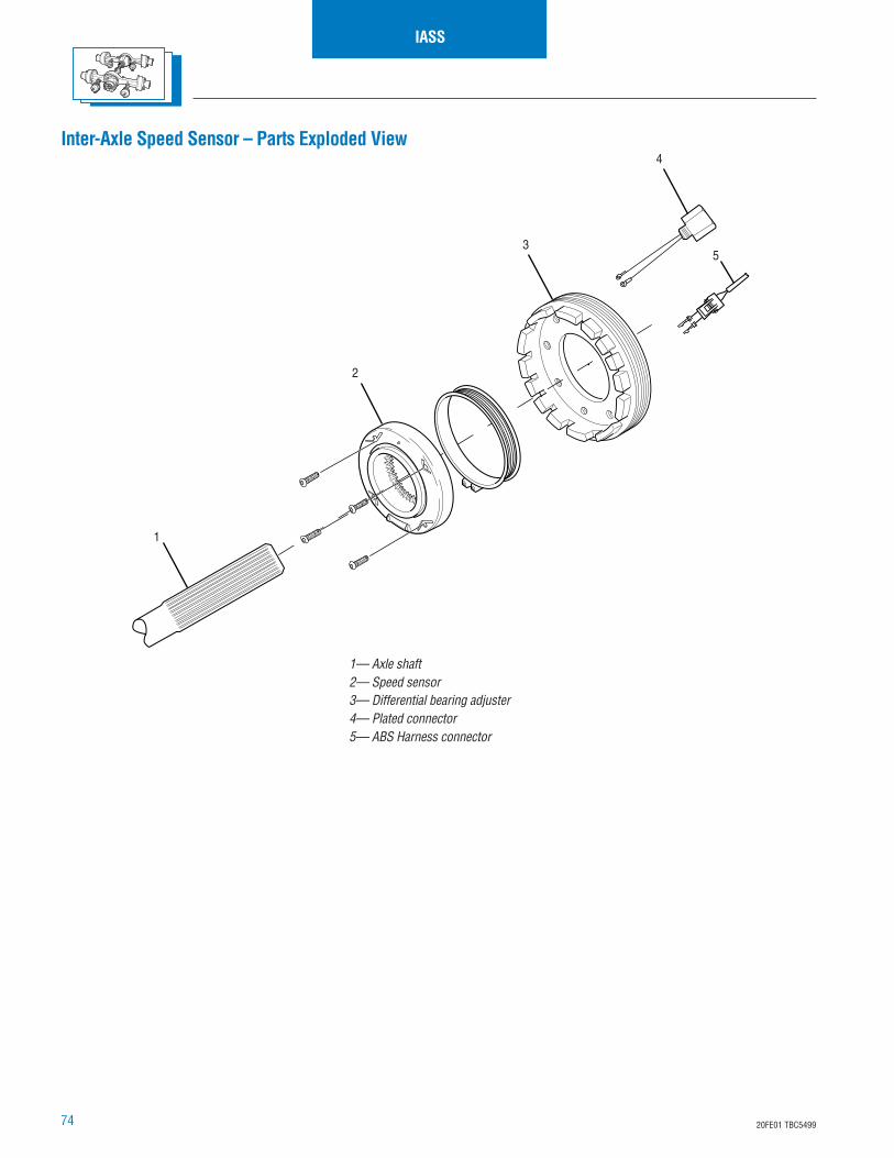
74 20FE01 TBC5499
IASS
1— Axle shaft2— Speed sensor3— Differential bearing adjuster4— Plated connector5— ABS Harness connector
1
3
4
5
2
Inter-Axle Speed Sensor – Parts Exploded View
7520FE01 TBC5499
Disassemble Inter-Axle Speed Sensor
The design of the drive axle sensor allows replacement of severalindividual components without disassembling the complete sensorsystem. For example:
• The differential bearing adjuster does not need to be removed inorder to replace any other component.
• The sensor and rotor can be replaced without removing orreplacing the plated connector.
At every stage of drive axle service, try to isolate the problem tospecific components in order to avoid unnecessary disassembly.
1. Disconnect two wires from sensor terminals.
2. Carefully inspect wires and connector. If connector is intactand if there is no prior indication that connectors and wiresrequire replacement, do not unscrew plated connector. Thesensor may be replaced without replacing connector andwire.
3. Remove four screws from face of sensor.
4. Remove sensor from differential bearing adjuster.
IASS
Overhaul Inter-Axle Speed Sensor
NOTE: If plated connector was damaged during axle disassembly or ifthere is indication of a wiring fault, the connector assembly must bereplaced.
There are two different connectors with two different lengths ofterminal wires. See Inter-Axle Speed Sensor Service ManualAXSM-0034.
To install new connector:
1. Clean threaded hole in carrier and wire path to allow properseal for new connector. (Male threads on the new connectorhave microencapsulated Loctite).
2. Insert connector and torque to 20–28 ft. lbs. (27–38 N•m).
3. Route wires to the sensor location.
If sensor assembly is to be replaced, install new sensor beforefinishing installation of new connector. The final position of thesensor terminals must be fixed before wires can be sealed in place.
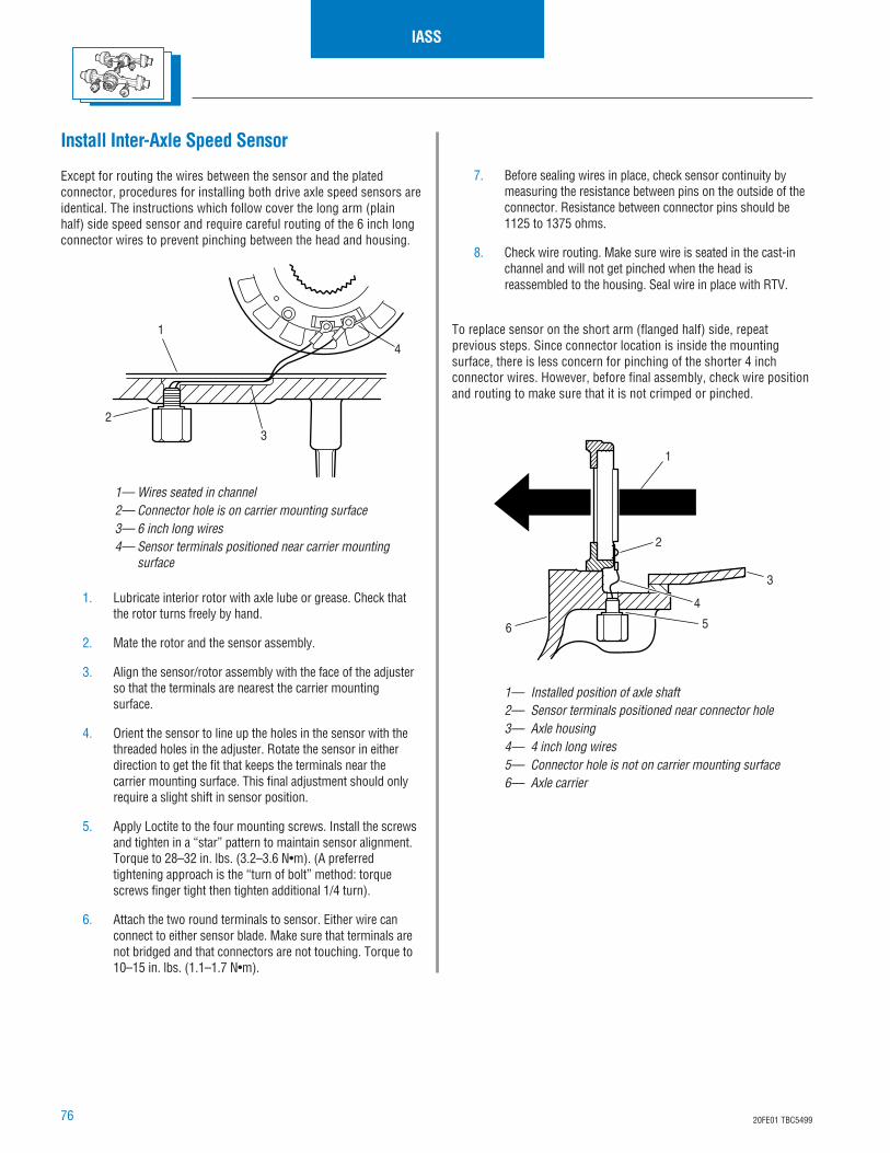
76 20FE01 TBC5499
Install Inter-Axle Speed Sensor
Except for routing the wires between the sensor and the platedconnector, procedures for installing both drive axle speed sensors areidentical. The instructions which follow cover the long arm (plainhalf) side speed sensor and require careful routing of the 6 inch longconnector wires to prevent pinching between the head and housing.
1. Lubricate interior rotor with axle lube or grease. Check thatthe rotor turns freely by hand.
2. Mate the rotor and the sensor assembly.
3. Align the sensor/rotor assembly with the face of the adjusterso that the terminals are nearest the carrier mountingsurface.
4. Orient the sensor to line up the holes in the sensor with thethreaded holes in the adjuster. Rotate the sensor in eitherdirection to get the fit that keeps the terminals near thecarrier mounting surface. This final adjustment should onlyrequire a slight shift in sensor position.
5. Apply Loctite to the four mounting screws. Install the screwsand tighten in a “star” pattern to maintain sensor alignment.Torque to 28–32 in. lbs. (3.2–3.6 N•m). (A preferredtightening approach is the “turn of bolt” method: torquescrews finger tight then tighten additional 1/4 turn).
6. Attach the two round terminals to sensor. Either wire canconnect to either sensor blade. Make sure that terminals arenot bridged and that connectors are not touching. Torque to10–15 in. lbs. (1.1–1.7 N•m).
IASS
1— Wires seated in channel2— Connector hole is on carrier mounting surface3— 6 inch long wires4— Sensor terminals positioned near carrier mounting
surface
1
23
4
7. Before sealing wires in place, check sensor continuity bymeasuring the resistance between pins on the outside of theconnector. Resistance between connector pins should be1125 to 1375 ohms.
8. Check wire routing. Make sure wire is seated in the cast-inchannel and will not get pinched when the head isreassembled to the housing. Seal wire in place with RTV.
To replace sensor on the short arm (flanged half) side, repeatprevious steps. Since connector location is inside the mountingsurface, there is less concern for pinching of the shorter 4 inchconnector wires. However, before final assembly, check wire positionand routing to make sure that it is not crimped or pinched.
1— Installed position of axle shaft2— Sensor terminals positioned near connector hole3— Axle housing4— 4 inch long wires5— Connector hole is not on carrier mounting surface6— Axle carrier
2
1
3
4
56
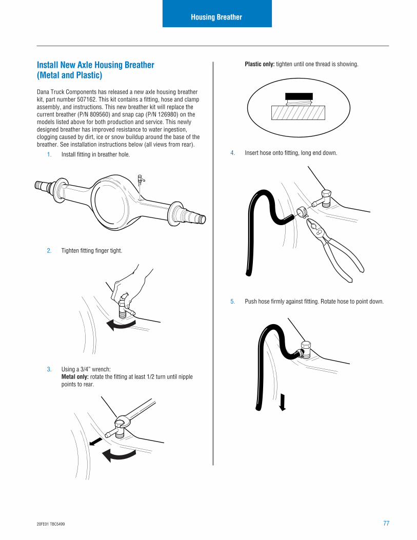
7720FE01 TBC5499
Housing Breather
Install New Axle Housing Breather(Metal and Plastic)
Dana Truck Components has released a new axle housing breatherkit, part number 507162. This kit contains a fitting, hose and clampassembly, and instructions. This new breather kit will replace thecurrent breather (P/N 809560) and snap cap (P/N 126980) on themodels listed above for both production and service. This newlydesigned breather has improved resistance to water ingestion,clogging caused by dirt, ice or snow buildup around the base of thebreather. See installation instructions below (all views from rear).
1. Install fitting in breather hole.
2. Tighten fitting finger tight.
3. Using a 3/4” wrench:Metal only: rotate the fitting at least 1/2 turn until nipplepoints to rear.
Plastic only: tighten until one thread is showing.
4. Insert hose onto fitting, long end down.
5. Push hose firmly against fitting. Rotate hose to point down.
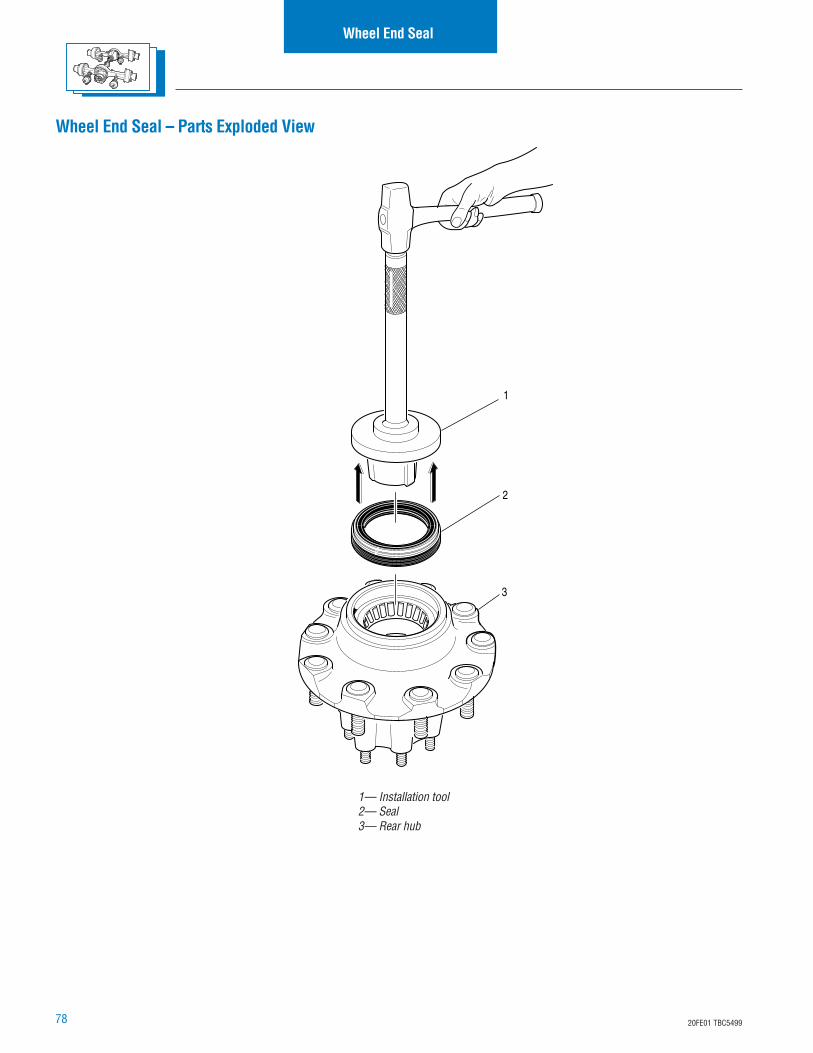
78 20FE01 TBC5499
1— Installation tool2— Seal3— Rear hub
Wheel End Seal – Parts Exploded View
Wheel End Seal
1
2
3
7920FE01 TBC5499
6. Clean hub cavity and bearing bores before reassembly. Besure to remove contaminants from all recesses and corners.
7. Clean bearings thoroughly with solvent and examine fordamage. Replace damaged or worn bearings.
IMPORTANT: Always use the seal installation tool specifiedby the seal manufacturer. Using an improper tool candistort or damage the seal and cause premature sealfailure.
Install Wheel End Seal
1. Before installation, lubricate the following with the samelubricant used in the axle sump.
• Inner bearing
• Wheel seal (follow the directions provided by theseal supplier)
2. Place seal on installation tool.
3. Drive seal with installation tool onto hub.
Wheel End Seal
Remove and Overhaul Wheel End Seal
WARNING: Never work under a vehicle supported by onlya jack. Always support vehicle with stands. Block thewheels and make sure the vehicle will not roll beforereleasing the brakes.
IMPORTANT: Wheel end seals can be easily damagedduring handling. Leave the seal in its package untilinstallation to prevent damage or contamination.
1. Remove outer bearing and wheel.
2. Remove oil seal.
3. Remove inner bearing.
4. Remove old wear sleeve (2-piece design only) with a ballpeen hammer and discard.
CAUTION: Do not cut through the old wear sleeve. Damageto the housing may result.
5. Inspect spindle journal and hub bore for scratches or burrs.Recondition with an emery cloth as required.
NOTE: Deep gouges can be repaired by filling gouge with hardeninggasket cement and smoothing with emery cloth.
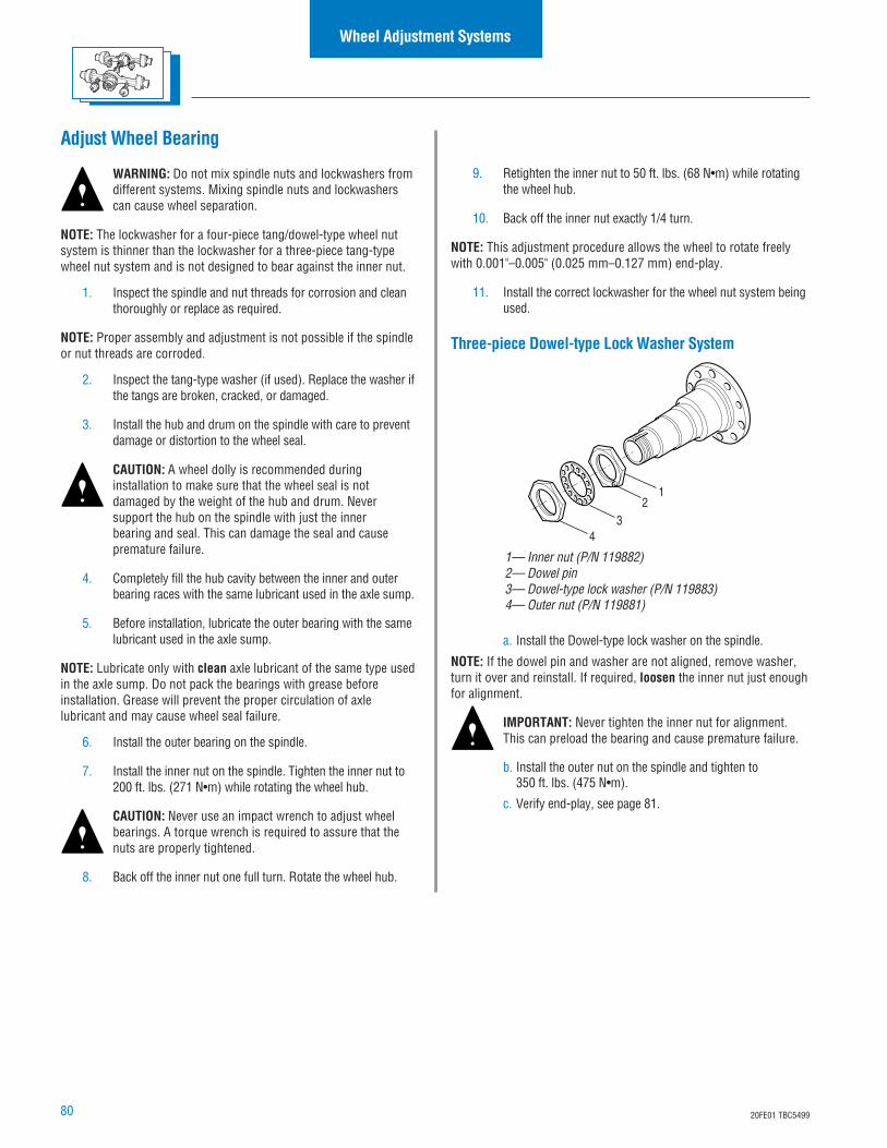
80 20FE01 TBC5499
Wheel Adjustment Systems
Adjust Wheel Bearing
WARNING: Do not mix spindle nuts and lockwashers fromdifferent systems. Mixing spindle nuts and lockwasherscan cause wheel separation.
NOTE: The lockwasher for a four-piece tang/dowel-type wheel nutsystem is thinner than the lockwasher for a three-piece tang-typewheel nut system and is not designed to bear against the inner nut.
1. Inspect the spindle and nut threads for corrosion and cleanthoroughly or replace as required.
NOTE: Proper assembly and adjustment is not possible if the spindleor nut threads are corroded.
2. Inspect the tang-type washer (if used). Replace the washer ifthe tangs are broken, cracked, or damaged.
3. Install the hub and drum on the spindle with care to preventdamage or distortion to the wheel seal.
CAUTION: A wheel dolly is recommended duringinstallation to make sure that the wheel seal is notdamaged by the weight of the hub and drum. Neversupport the hub on the spindle with just the innerbearing and seal. This can damage the seal and causepremature failure.
4. Completely fill the hub cavity between the inner and outerbearing races with the same lubricant used in the axle sump.
5. Before installation, lubricate the outer bearing with the samelubricant used in the axle sump.
NOTE: Lubricate only with clean axle lubricant of the same type usedin the axle sump. Do not pack the bearings with grease beforeinstallation. Grease will prevent the proper circulation of axlelubricant and may cause wheel seal failure.
6. Install the outer bearing on the spindle.
7. Install the inner nut on the spindle. Tighten the inner nut to200 ft. lbs. (271 N•m) while rotating the wheel hub.
CAUTION: Never use an impact wrench to adjust wheelbearings. A torque wrench is required to assure that thenuts are properly tightened.
8. Back off the inner nut one full turn. Rotate the wheel hub.
9. Retighten the inner nut to 50 ft. lbs. (68 N•m) while rotatingthe wheel hub.
10. Back off the inner nut exactly 1/4 turn.
NOTE: This adjustment procedure allows the wheel to rotate freelywith 0.001"–0.005" (0.025 mm–0.127 mm) end-play.
11. Install the correct lockwasher for the wheel nut system beingused.
Three-piece Dowel-type Lock Washer System
a. Install the Dowel-type lock washer on the spindle.
NOTE: If the dowel pin and washer are not aligned, remove washer,turn it over and reinstall. If required, loosen the inner nut just enoughfor alignment.
IMPORTANT: Never tighten the inner nut for alignment.This can preload the bearing and cause premature failure.
b. Install the outer nut on the spindle and tighten to350 ft. lbs. (475 N•m).
c. Verify end-play, see page 81.
12
34
1— Inner nut (P/N 119882)2— Dowel pin3— Dowel-type lock washer (P/N 119883)4— Outer nut (P/N 119881)
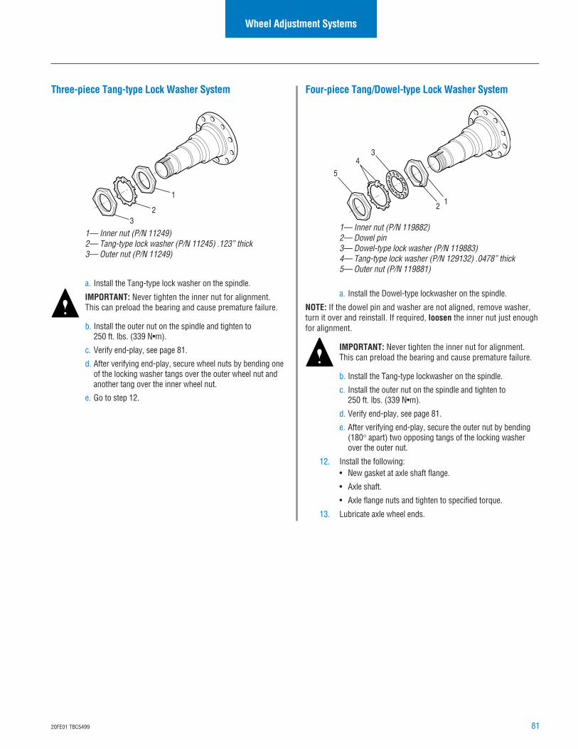
8120FE01 TBC5499
Four-piece Tang/Dowel-type Lock Washer System
a. Install the Dowel-type lockwasher on the spindle.
NOTE: If the dowel pin and washer are not aligned, remove washer,turn it over and reinstall. If required, loosen the inner nut just enoughfor alignment.
IMPORTANT: Never tighten the inner nut for alignment.This can preload the bearing and cause premature failure.
b. Install the Tang-type lockwasher on the spindle.
c. Install the outer nut on the spindle and tighten to250 ft. lbs. (339 N•m).
d. Verify end-play, see page 81.
e. After verifying end-play, secure the outer nut by bending(180° apart) two opposing tangs of the locking washerover the outer nut.
12. Install the following:• New gasket at axle shaft flange.
• Axle shaft.
• Axle flange nuts and tighten to specified torque.
13. Lubricate axle wheel ends.
12
34
5
1— Inner nut (P/N 119882)2— Dowel pin3— Dowel-type lock washer (P/N 119883)4— Tang-type lock washer (P/N 129132) .0478” thick5— Outer nut (P/N 119881)
Wheel Adjustment Systems
Three-piece Tang-type Lock Washer System
a. Install the Tang-type lock washer on the spindle.
IMPORTANT: Never tighten the inner nut for alignment.This can preload the bearing and cause premature failure.
b. Install the outer nut on the spindle and tighten to250 ft. lbs. (339 N•m).
c. Verify end-play, see page 81.
d. After verifying end-play, secure wheel nuts by bending oneof the locking washer tangs over the outer wheel nut andanother tang over the inner wheel nut.
e. Go to step 12.
1
23
1— Inner nut (P/N 11249)2— Tang-type lock washer (P/N 11245) .123” thick3— Outer nut (P/N 11249)
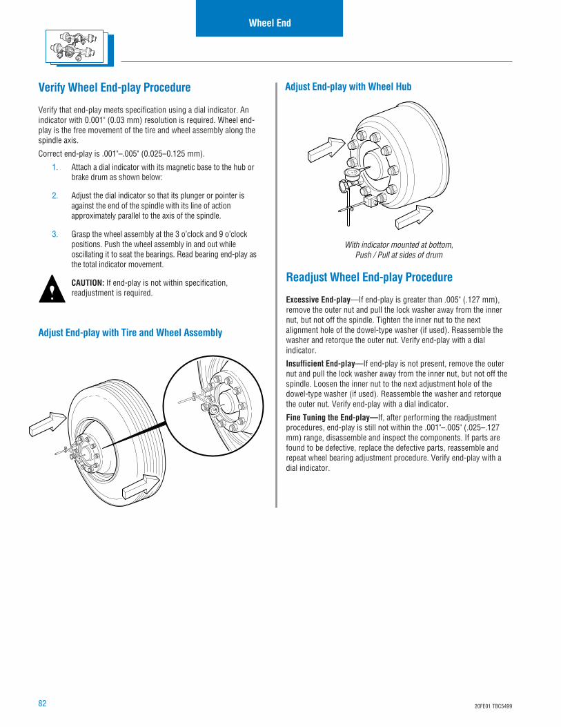
82 20FE01 TBC5499
Wheel End
Verify Wheel End-play Procedure
Verify that end-play meets specification using a dial indicator. Anindicator with 0.001" (0.03 mm) resolution is required. Wheel end-play is the free movement of the tire and wheel assembly along thespindle axis.
Correct end-play is .001"–.005" (0.025–0.125 mm).
1. Attach a dial indicator with its magnetic base to the hub orbrake drum as shown below:
2. Adjust the dial indicator so that its plunger or pointer isagainst the end of the spindle with its line of actionapproximately parallel to the axis of the spindle.
3. Grasp the wheel assembly at the 3 o’clock and 9 o’clockpositions. Push the wheel assembly in and out whileoscillating it to seat the bearings. Read bearing end-play asthe total indicator movement.
CAUTION: If end-play is not within specification,readjustment is required.
Adjust End-play with Tire and Wheel Assembly
Readjust Wheel End-play Procedure
Excessive End-play—If end-play is greater than .005" (.127 mm),remove the outer nut and pull the lock washer away from the innernut, but not off the spindle. Tighten the inner nut to the nextalignment hole of the dowel-type washer (if used). Reassemble thewasher and retorque the outer nut. Verify end-play with a dialindicator.
Insufficient End-play—If end-play is not present, remove the outernut and pull the lock washer away from the inner nut, but not off thespindle. Loosen the inner nut to the next adjustment hole of thedowel-type washer (if used). Reassemble the washer and retorquethe outer nut. Verify end-play with a dial indicator.
Fine Tuning the End-play—If, after performing the readjustmentprocedures, end-play is still not within the .001"–.005" (.025–.127mm) range, disassemble and inspect the components. If parts arefound to be defective, replace the defective parts, reassemble andrepeat wheel bearing adjustment procedure. Verify end-play with adial indicator.
Adjust End-play with Wheel Hub
With indicator mounted at bottom,Push / Pull at sides of drum
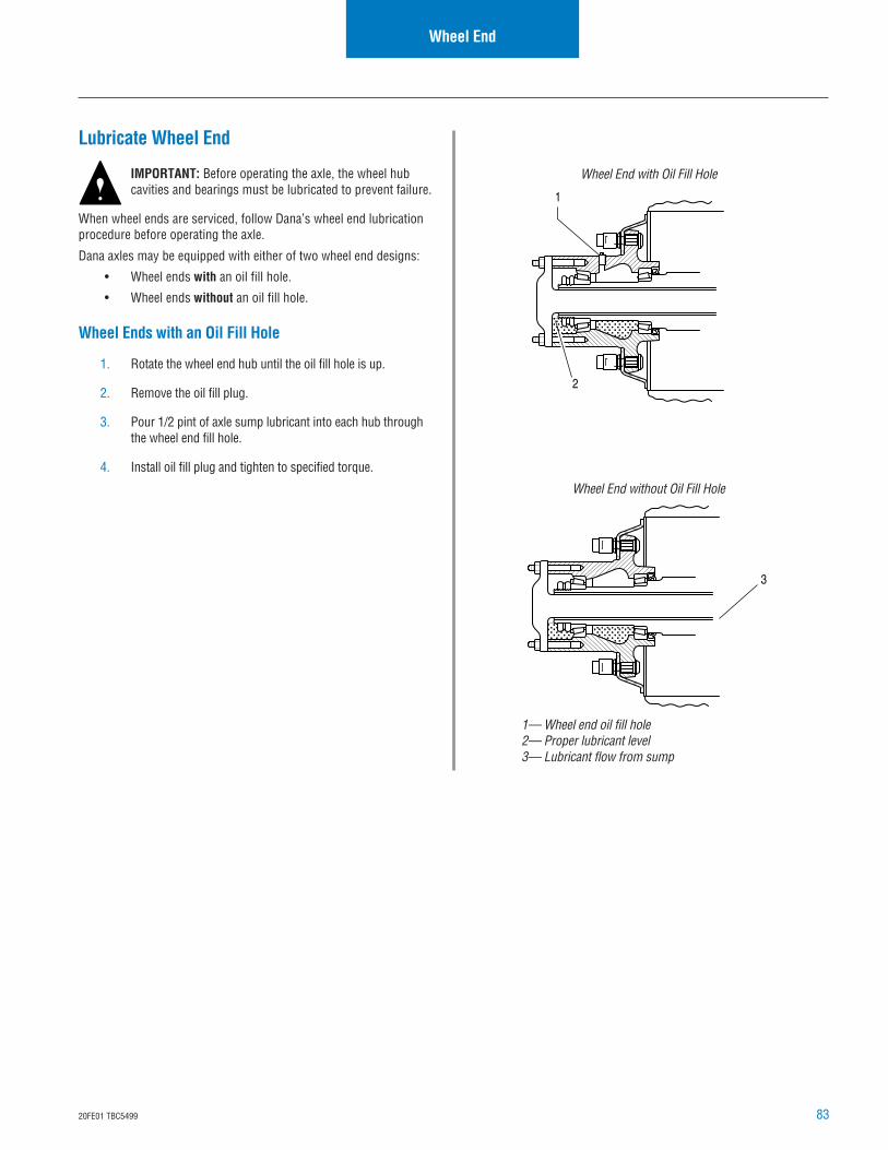
8320FE01 TBC5499
Wheel End
1— Wheel end oil fill hole2— Proper lubricant level3— Lubricant flow from sump
Lubricate Wheel End
IMPORTANT: Before operating the axle, the wheel hubcavities and bearings must be lubricated to prevent failure.
When wheel ends are serviced, follow Dana’s wheel end lubricationprocedure before operating the axle.
Dana axles may be equipped with either of two wheel end designs:
• Wheel ends with an oil fill hole.
• Wheel ends without an oil fill hole.
Wheel Ends with an Oil Fill Hole
1. Rotate the wheel end hub until the oil fill hole is up.
2. Remove the oil fill plug.
3. Pour 1/2 pint of axle sump lubricant into each hub throughthe wheel end fill hole.
4. Install oil fill plug and tighten to specified torque.
3
1
2
Wheel End with Oil Fill Hole
Wheel End without Oil Fill Hole
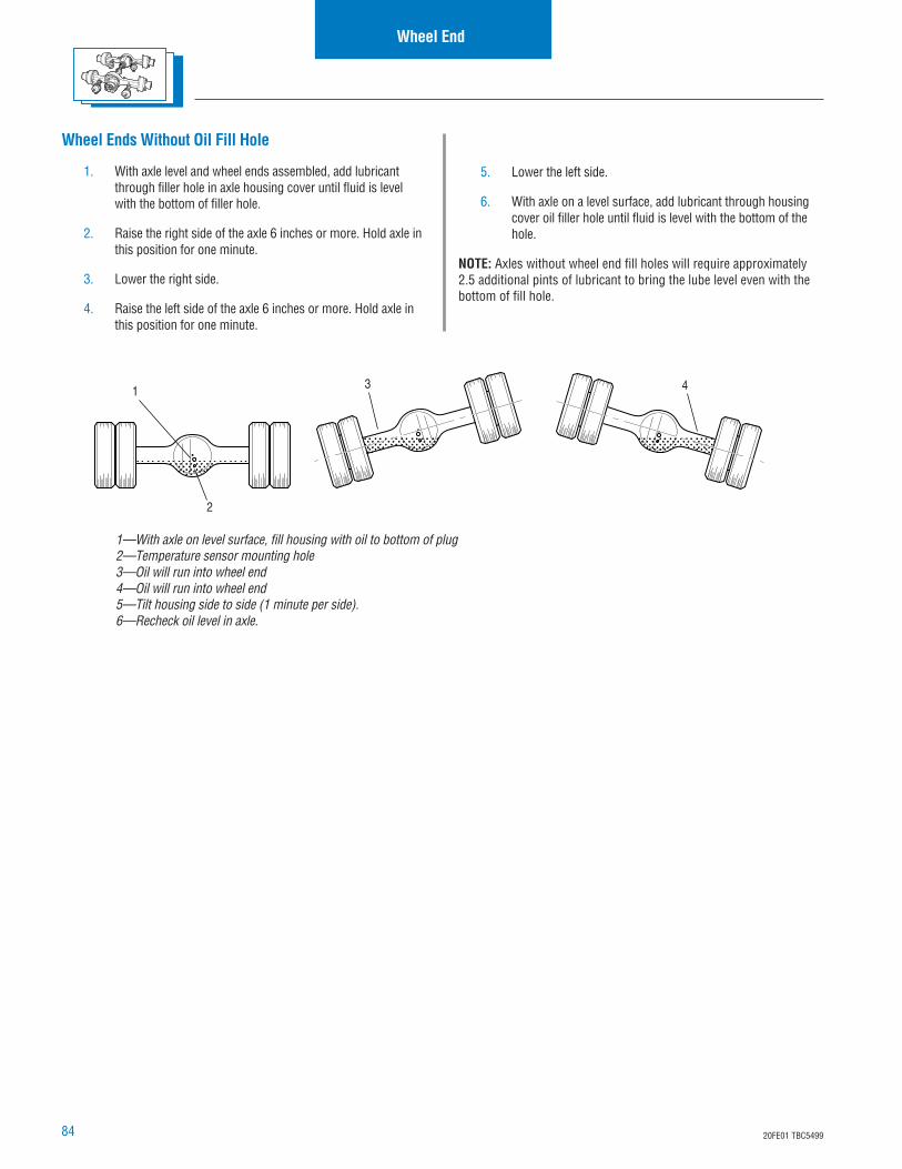
84 20FE01 TBC5499
1—With axle on level surface, fill housing with oil to bottom of plug2—Temperature sensor mounting hole3—Oil will run into wheel end4—Oil will run into wheel end5—Tilt housing side to side (1 minute per side).6—Recheck oil level in axle.
Wheel Ends Without Oil Fill Hole
1. With axle level and wheel ends assembled, add lubricantthrough filler hole in axle housing cover until fluid is levelwith the bottom of filler hole.
2. Raise the right side of the axle 6 inches or more. Hold axle inthis position for one minute.
3. Lower the right side.
4. Raise the left side of the axle 6 inches or more. Hold axle inthis position for one minute.
1 3 4
2
5. Lower the left side.
6. With axle on a level surface, add lubricant through housingcover oil filler hole until fluid is level with the bottom of thehole.
NOTE: Axles without wheel end fill holes will require approximately2.5 additional pints of lubricant to bring the lube level even with thebottom of fill hole.
Wheel End
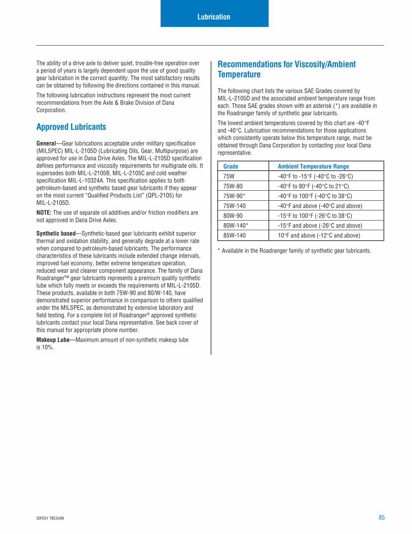
8520FE01 TBC5499
Lubrication
The ability of a drive axle to deliver quiet, trouble-free operation overa period of years is largely dependent upon the use of good qualitygear lubrication in the correct quantity. The most satisfactory resultscan be obtained by following the directions contained in this manual.
The following lubrication instructions represent the most currentrecommendations from the Axle & Brake Division of DanaCorporation.
Approved Lubricants
General—Gear lubrications acceptable under military specification(MILSPEC) MIL-L-2105D (Lubricating Oils, Gear, Multipurpose) areapproved for use in Dana Drive Axles. The MIL-L-2105D specificationdefines performance and viscosity requirements for multigrade oils. Itsupersedes both MIL-L-2105B, MIL-L-2105C and cold weatherspecification MIL-L-10324A. This specification applies to bothpetroleum-based and synthetic based gear lubricants if they appearon the most current “Qualified Products List” (QPL-2105) forMIL-L-2105D.
NOTE: The use of separate oil additives and/or friction modifiers arenot approved in Dana Drive Axles.
Synthetic based—Synthetic-based gear lubricants exhibit superiorthermal and oxidation stability, and generally degrade at a lower ratewhen compared to petroleum-based lubricants. The performancecharacteristics of these lubricants include extended change intervals,improved fuel economy, better extreme temperature operation,reduced wear and cleaner component appearance. The family of DanaRoadranger™ gear lubricants represents a premium quality syntheticlube which fully meets or exceeds the requirements of MIL-L-2105D.These products, available in both 75W-90 and 80/W-140, havedemonstrated superior performance in comparison to others qualifiedunder the MILSPEC, as demonstrated by extensive laboratory andfield testing. For a complete list of Roadranger® approved syntheticlubricants contact your local Dana representative. See back cover ofthis manual for appropriate phone number.
Makeup Lube—Maximum amount of non-synthetic makeup lubeis 10%.
Recommendations for Viscosity/AmbientTemperature
The following chart lists the various SAE Grades covered byMIL-L-2105D and the associated ambient temperature range fromeach. Those SAE grades shown with an asterisk (*) are available inthe Roadranger family of synthetic gear lubricants.
The lowest ambient temperatures covered by this chart are -40°Fand -40°C. Lubrication recommendations for those applicationswhich consistently operate below this temperature range, must beobtained through Dana Corporation by contacting your local Danarepresentative.
Grade Ambient Temperature Range
75W -40°F to -15°F (-40°C to -26°C)
75W-80 -40°F to 80°F (-40°C to 21°C)
75W-90* -40°F to 100°F (-40°C to 38°C)
75W-140 -40°F and above (-40°C and above)
80W-90 -15°F to 100°F (-26°C to 38°C)
80W-140* -15°F and above (-26°C and above)
85W-140 10°F and above (-12°C and above)
* Available in the Roadranger family of synthetic gear lubricants.
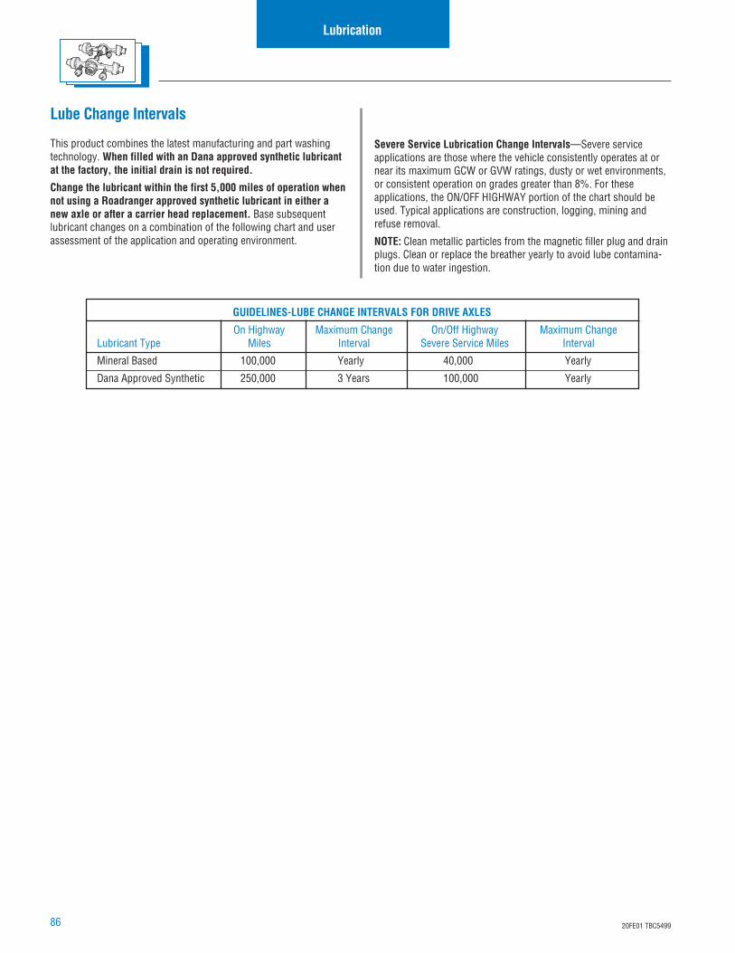
86 20FE01 TBC5499
Lubrication
Lube Change Intervals
This product combines the latest manufacturing and part washingtechnology. When filled with an Dana approved synthetic lubricantat the factory, the initial drain is not required.
Change the lubricant within the first 5,000 miles of operation whennot using a Roadranger approved synthetic lubricant in either anew axle or after a carrier head replacement. Base subsequentlubricant changes on a combination of the following chart and userassessment of the application and operating environment.
Severe Service Lubrication Change Intervals—Severe serviceapplications are those where the vehicle consistently operates at ornear its maximum GCW or GVW ratings, dusty or wet environments,or consistent operation on grades greater than 8%. For theseapplications, the ON/OFF HIGHWAY portion of the chart should beused. Typical applications are construction, logging, mining andrefuse removal.
NOTE: Clean metallic particles from the magnetic filler plug and drainplugs. Clean or replace the breather yearly to avoid lube contamina-tion due to water ingestion.
GUIDELINES-LUBE CHANGE INTERVALS FOR DRIVE AXLES
On Highway Maximum Change On/Off Highway Maximum ChangeLubricant Type Miles Interval Severe Service Miles Interval
Mineral Based 100,000 Yearly 40,000 Yearly
Dana Approved Synthetic 250,000 3 Years 100,000 Yearly
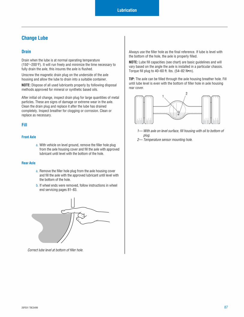
8720FE01 TBC5499
Correct lube level at bottom of filler hole.
1— With axle on level surface, fill housing with oil to bottom ofplug.
2— Temperature sensor mounting hole.
Change Lube
Drain
Drain when the lube is at normal operating temperature(150°–200°F). It will run freely and minimize the time necessary tofully drain the axle, this insures the axle is flushed.
Unscrew the magnetic drain plug on the underside of the axlehousing and allow the lube to drain into a suitable container.
NOTE: Dispose of all used lubricants properly by following disposalmethods approved for mineral or synthetic based oils.
After initial oil change, inspect drain plug for large quantities of metalparticles. These are signs of damage or extreme wear in the axle.Clean the drain plug and replace it after the lube has drainedcompletely. Inspect breather for clogging or corrosion. Clean orreplace as necessary.
Fill
Front Axle
a. With vehicle on level ground, remove the filler hole plugfrom the axle housing cover and fill the axle with approvedlubricant until level with the bottom of the hole.
Rear Axle
a. Remove the filler hole plug from the axle housing coverand fill the axle with the approved lubricant until level withthe bottom of the hole.
b. If wheel ends were removed, follow instructions in wheelend servicing pages 81–83.
Always use the filler hole as the final reference. If lube is level withthe bottom of the hole, the axle is properly filled.
NOTE: Lube fill capacities (see chart) are basic guidelines and willvary based on the angle the axle is installed in a particular chassis.Torque fill plug to 40–60 ft. lbs. (54–82 N•m).
TIP: The axle can be filled through the axle housing breather hole. Filluntil lube level is even with the bottom of filler hole in axle housingrear cover.
Lubrication
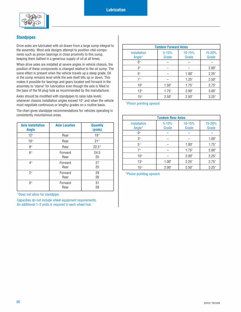
88 20FE01 TBC5499
Lubrication
Axle Installation Axle Location QuantityAngle (pints)
12° Rear 19*
10° Rear 21*
8° Rear 22.5*
6° Forward 24.5Rear 25
4° Forward 27Rear 25
2° Forward 29Rear 26
0° Forward 31Rear 28
*Does not allow for standpipe.
Capacities do not include wheel equipment requirements.An additional 1–2 pints is required in each wheel hub.
Standpipes
Drive axles are lubricated with oil drawn from a large sump integral tothe assembly. Most axle designs attempt to position vital compo-nents such as pinion bearings in close proximity to this sump,keeping them bathed in a generous supply of oil at all times.
When drive axles are installed at severe angles in vehicle chassis, theposition of these components is changed relative to the oil sump. Thesame effect is present when the vehicle travels up a steep grade. Oilin the sump remains level while the axle itself tilts up or down. Thismakes it possible for bearings and gears located well forward in theassembly to "starve" for lubrication even though the axle is filled tothe base of the fill plug hole as recommended by the manufacturer.
Axles should be modified with standpipes to raise lube levelswhenever chassis installation angles exceed 10° and when the vehiclemust negotiate continuous or lengthy grades on a routine basis.
The chart gives standpipe recommendations for vehicles operating inconsistently mountainous areas.
Tandem Rear Axles
Installation 5-10% 10-15% 15-20%Angle* Grade Grade Grade
0° – – –
3° – – 1.00"
5° – 1.00" 1.75"
7° – 1.75" 2.00"
10° – 2.00" 2.25"
13° 1.00" 2.25" 2.75"
15° 2.00" 2.50" 3.25"
*Pinion pointing upward
Tandem Forward Axles
Installation 5-10% 10-15% 15-20%Angle* Grade Grade Grade
0° – – –
3° – – 2.00"
5° – 1.00" 2.25"
7° – 1.25" 2.50"
10° 1.50" 1.75" 2.75"
13° 1.75" 2.00" 3.00"
15° 2.50" 2.50" 3.25"
*Pinion pointing upward
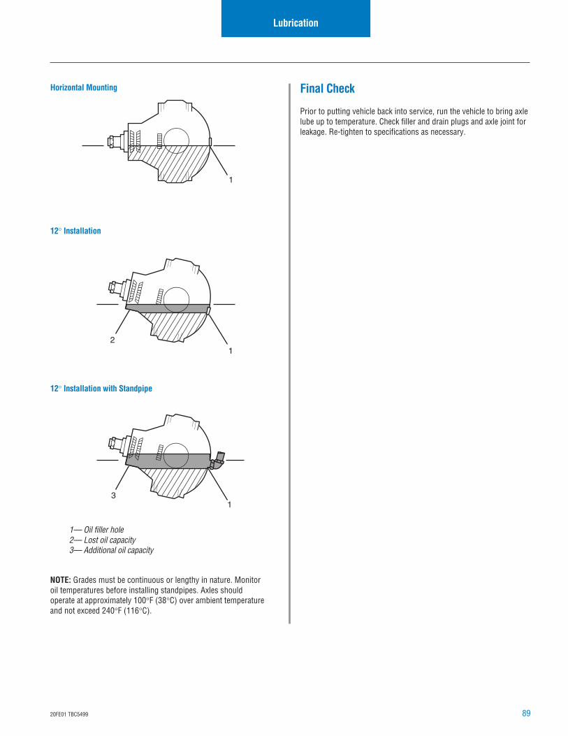
8920FE01 TBC5499
1
12
31
NOTE: Grades must be continuous or lengthy in nature. Monitoroil temperatures before installing standpipes. Axles shouldoperate at approximately 100°F (38°C) over ambient temperatureand not exceed 240°F (116°C).
1— Oil filler hole2— Lost oil capacity3— Additional oil capacity
Horizontal Mounting
12° Installation
12° Installation with Standpipe
Final Check
Prior to putting vehicle back into service, run the vehicle to bring axlelube up to temperature. Check filler and drain plugs and axle joint forleakage. Re-tighten to specifications as necessary.
Lubrication
Appendix A-120FE01 TBC5499
Proper Vehicle Towing
Without Wheel Differential Lock
Lift the drive wheels completely off of the ground or damage willoccur.
WARNING: Do not lift the front wheels (non-drive wheels).This alters the oil’s position in the drive axle, draining itaway from the drive pinion and its bearings. If the pinion isrotated under these conditions for any period of time,bearings will overheat resulting in axle damage or failure.
If this is impossible to lift the drive wheels, remove all axle shafts toprevent gear rotation and cap the wheel hubs to prevent loss oflubricant and a possible road hazard. See the following sectionProper Vehicle Towing with Wheel Differential Lock for removalprocedure.
Towing
With Wheel Differential Lock
Follow this procedure to remove all axle shafts preventing gearrotation with the drive wheels and possible lubrication damage.
1. Engage the wheel differential lock, indicator light is on (movevehicle to verify engagement).
2. Shift transmission into neutral.
3. With vehicle stationary, release the air pressure on the wheeldifferential lock shift system and apply the parking brake.
4. Disconnect the air supply and fitting at the shift cylinder.
5. Install the shipping capscrew 128642 (.250 X 18 X 1.5")NPSM screw. GM models require part number 128274(M12 X 1.5 X 38mm) screw. Tighten cap screw to manuallyengage the wheel differential lock until the indicator light ison and the differential lock is completely engaged.
6. Remove the axle shafts.
7. Install temporary cover on hub to prevent contaminationentering and also to prevent the loss of lubricant.
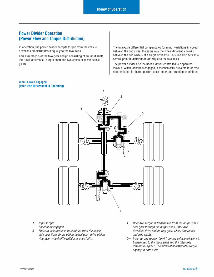
Appendix B-120FE01 TBC5499
Power Divider Operation(Power Flow and Torque Distribution)
In operation, the power divider accepts torque from the vehicledriveline and distributes it equally to the two axles.
This assembly is of the two-gear design consisting of an input shaft,inter-axle differential, output shaft and two constant-mesh helicalgears.
Theory of Operation
1— Input torque2— Lockout disengaged3— Forward axle torque is transmitted from the helical
side gear through the pinion helical gear, drive pinion,ring gear, wheel differential and axle shafts.
The inter-axle differential compensates for minor variations in speedbetween the two axles, the same way the wheel differential worksbetween the two wheels of a single drive axle. This unit also acts as acentral point in distribution of torque to the two axles.
The power divider also includes a driver-controlled, air-operatedlockout. When lockout is engaged, it mechanically prevents inter-axledifferentiation for better performance under poor traction conditions.
1
2
3
5
4
4— Rear axle torque is transmitted from the output shaftside gear through the output shaft, inter-axledriveline, drive pinion, ring gear, wheel differentialand axle shafts.
5— Input torque (power flow) from the vehicle driveline istransmitted to the input shaft and the inter-axledifferential spider. The differential distributes torqueequally to both axles.
With Lockout Engaged(Inter-Axle Differential is Operating)
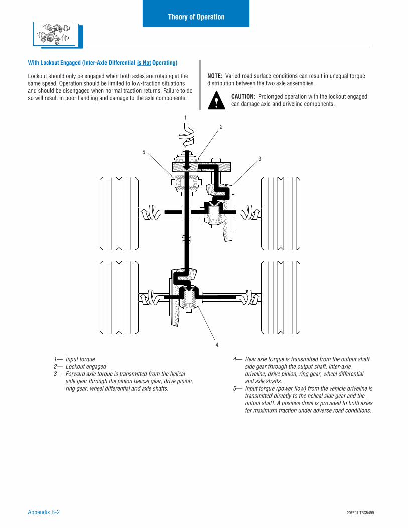
Appendix B-2 20FE01 TBC5499
NOTE: Varied road surface conditions can result in unequal torquedistribution between the two axle assemblies.
CAUTION: Prolonged operation with the lockout engagedcan damage axle and driveline components.
Theory of Operation
1
2
35
4
1— Input torque2— Lockout engaged3— Forward axle torque is transmitted from the helical
side gear through the pinion helical gear, drive pinion,ring gear, wheel differential and axle shafts.
With Lockout Engaged (Inter-Axle Differential is Not Operating)
Lockout should only be engaged when both axles are rotating at thesame speed. Operation should be limited to low-traction situationsand should be disengaged when normal traction returns. Failure to doso will result in poor handling and damage to the axle components.
4— Rear axle torque is transmitted from the output shaftside gear through the output shaft, inter-axledriveline, drive pinion, ring gear, wheel differentialand axle shafts.
5— Input torque (power flow) from the vehicle driveline istransmitted directly to the helical side gear and theoutput shaft. A positive drive is provided to both axlesfor maximum traction under adverse road conditions.
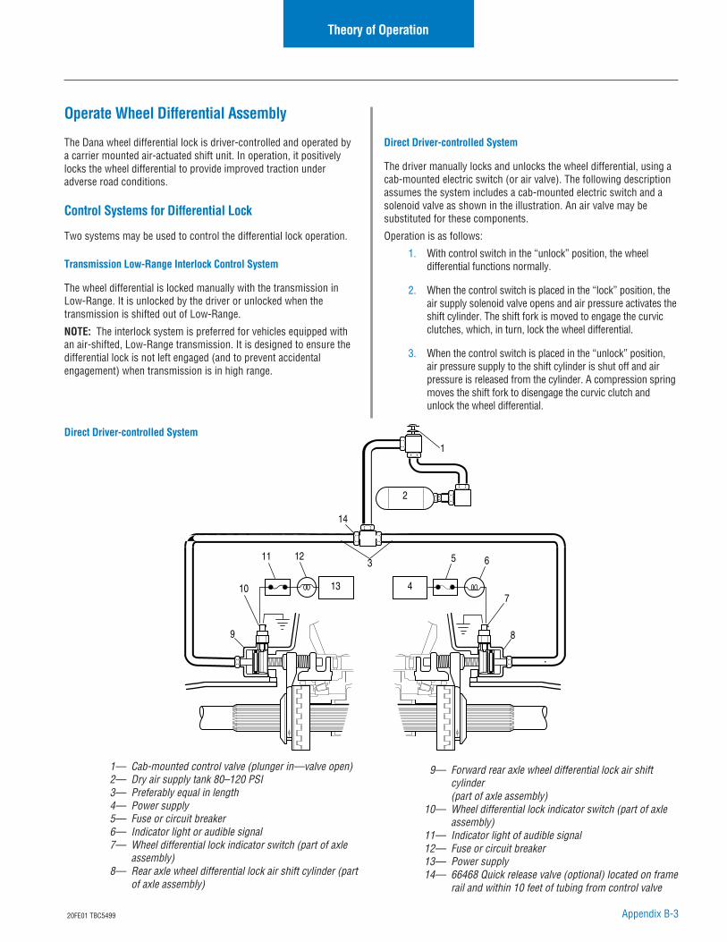
Appendix B-320FE01 TBC5499
Theory of Operation
2
1
14
9
10
11 612 5
13 4
8
7
3
Operate Wheel Differential Assembly
The Dana wheel differential lock is driver-controlled and operated bya carrier mounted air-actuated shift unit. In operation, it positivelylocks the wheel differential to provide improved traction underadverse road conditions.
Control Systems for Differential Lock
Two systems may be used to control the differential lock operation.
Transmission Low-Range Interlock Control System
The wheel differential is locked manually with the transmission inLow-Range. It is unlocked by the driver or unlocked when thetransmission is shifted out of Low-Range.
NOTE: The interlock system is preferred for vehicles equipped withan air-shifted, Low-Range transmission. It is designed to ensure thedifferential lock is not left engaged (and to prevent accidentalengagement) when transmission is in high range.
1— Cab-mounted control valve (plunger in—valve open)2— Dry air supply tank 80–120 PSI3— Preferably equal in length4— Power supply5— Fuse or circuit breaker6— Indicator light or audible signal7— Wheel differential lock indicator switch (part of axle
assembly)8— Rear axle wheel differential lock air shift cylinder (part
of axle assembly)
Direct Driver-controlled System
The driver manually locks and unlocks the wheel differential, using acab-mounted electric switch (or air valve). The following descriptionassumes the system includes a cab-mounted electric switch and asolenoid valve as shown in the illustration. An air valve may besubstituted for these components.
Operation is as follows:
1. With control switch in the “unlock” position, the wheeldifferential functions normally.
2. When the control switch is placed in the “lock” position, theair supply solenoid valve opens and air pressure activates theshift cylinder. The shift fork is moved to engage the curvicclutches, which, in turn, lock the wheel differential.
3. When the control switch is placed in the “unlock” position,air pressure supply to the shift cylinder is shut off and airpressure is released from the cylinder. A compression springmoves the shift fork to disengage the curvic clutch andunlock the wheel differential.
Direct Driver-controlled System
9— Forward rear axle wheel differential lock air shiftcylinder(part of axle assembly)
10— Wheel differential lock indicator switch (part of axleassembly)
11— Indicator light of audible signal12— Fuse or circuit breaker13— Power supply14— 66468 Quick release valve (optional) located on frame
rail and within 10 feet of tubing from control valve
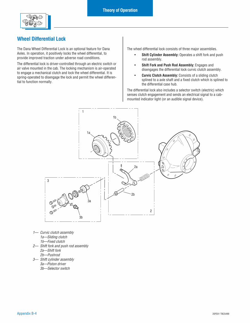
Appendix B-4 20FE01 TBC5499
Theory of Operation
1
1b
1a
2
2a
2b
3
3a
3b
Wheel Differential Lock
The Dana Wheel Differential Lock is an optional feature for DanaAxles. In operation, it positively locks the wheel differential, toprovide improved traction under adverse road conditions.
The differential lock is driver-controlled through an electric switch orair valve mounted in the cab. The locking mechanism is air-operatedto engage a mechanical clutch and lock the wheel differential. It isspring-operated to disengage the lock and permit the wheel differen-tial to function normally.
The wheel differential lock consists of three major assemblies.
• Shift Cylinder Assembly: Operates a shift fork and pushrod assembly.
• Shift Fork and Push Rod Assembly: Engages anddisengages the differential lock curvic clutch assembly.
• Curvic Clutch Assembly: Consists of a sliding clutchsplined to a axle shaft and a fixed clutch which is splined tothe differential case hub.
The differential lock also includes a selector switch (electric) whichsenses clutch engagement and sends an electrical signal to a cab-mounted indicator light (or an audible signal device).
1— Curvic clutch assembly1a—Sliding clutch1b—Fixed clutch
2— Shift fork and push rod assembly2a—Shift fork2b—Pushrod
3— Shift cylinder assembly3a—Piston driver3b—Selector switch
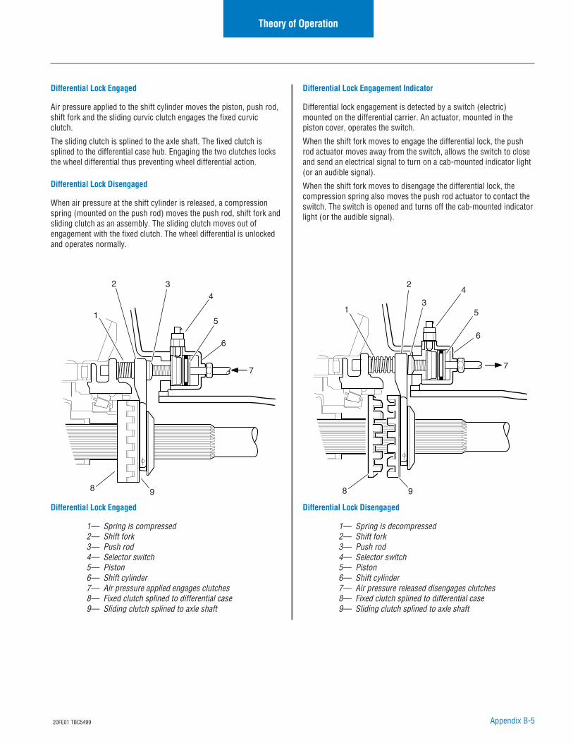
Appendix B-520FE01 TBC5499
Theory of Operation
1
2 34
5
6
7
8 9
1
2
3
4
5
6
7
8 9
Differential Lock Engaged
Air pressure applied to the shift cylinder moves the piston, push rod,shift fork and the sliding curvic clutch engages the fixed curvicclutch.
The sliding clutch is splined to the axle shaft. The fixed clutch issplined to the differential case hub. Engaging the two clutches locksthe wheel differential thus preventing wheel differential action.
Differential Lock Disengaged
When air pressure at the shift cylinder is released, a compressionspring (mounted on the push rod) moves the push rod, shift fork andsliding clutch as an assembly. The sliding clutch moves out ofengagement with the fixed clutch. The wheel differential is unlockedand operates normally.
Differential Lock Engagement Indicator
Differential lock engagement is detected by a switch (electric)mounted on the differential carrier. An actuator, mounted in thepiston cover, operates the switch.
When the shift fork moves to engage the differential lock, the pushrod actuator moves away from the switch, allows the switch to closeand send an electrical signal to turn on a cab-mounted indicator light(or an audible signal).
When the shift fork moves to disengage the differential lock, thecompression spring also moves the push rod actuator to contact theswitch. The switch is opened and turns off the cab-mounted indicatorlight (or the audible signal).
Differential Lock Engaged
1— Spring is compressed2— Shift fork3— Push rod4— Selector switch5— Piston6— Shift cylinder7— Air pressure applied engages clutches8— Fixed clutch splined to differential case9— Sliding clutch splined to axle shaft
Differential Lock Disengaged
1— Spring is decompressed2— Shift fork3— Push rod4— Selector switch5— Piston6— Shift cylinder7— Air pressure released disengages clutches8— Fixed clutch splined to differential case9— Sliding clutch splined to axle shaft

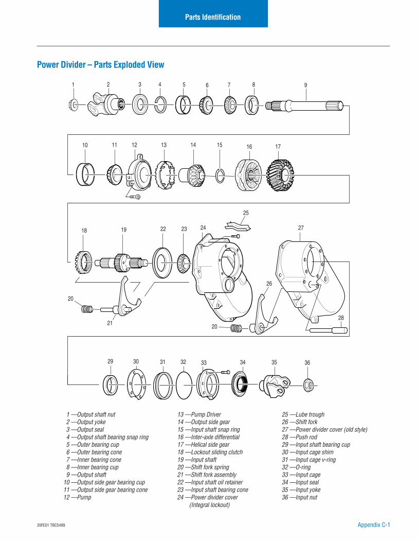
Appendix C-120FE01 TBC5499
Power Divider – Parts Exploded View
Parts Identification
18 19
10 14131211 15
30 33 3531 32 34 3629
16
7 91 3 52 4 6 8
17
22 23 24
21
26
27
28
25
20
20
1 —Output shaft nut2 —Output yoke3 —Output seal4 —Output shaft bearing snap ring5 —Outer bearing cup6 —Outer bearing cone7 —Inner bearing cone8 —Inner bearing cup9 —Output shaft
10 —Output side gear bearing cup11 —Output side gear bearing cone12 —Pump
13 —Pump Driver14 —Output side gear15 —Input shaft snap ring16 —Inter-axle differential17 —Helical side gear18 —Lockout sliding clutch19 —Input shaft20 —Shift fork spring21 —Shift fork assembly22 —Input shaft oil retainer23 —Input shaft bearing cone24 —Power divider cover
(Integral lockout)
25 —Lube trough26 —Shift fork27 —Power divider cover (old style)28 —Push rod29 —Input shaft bearing cup30 —Input cage shim31 —Input cage v-ring32 —O-ring33 —Input cage34 —Input seal35 —Input yoke36 —Input nut
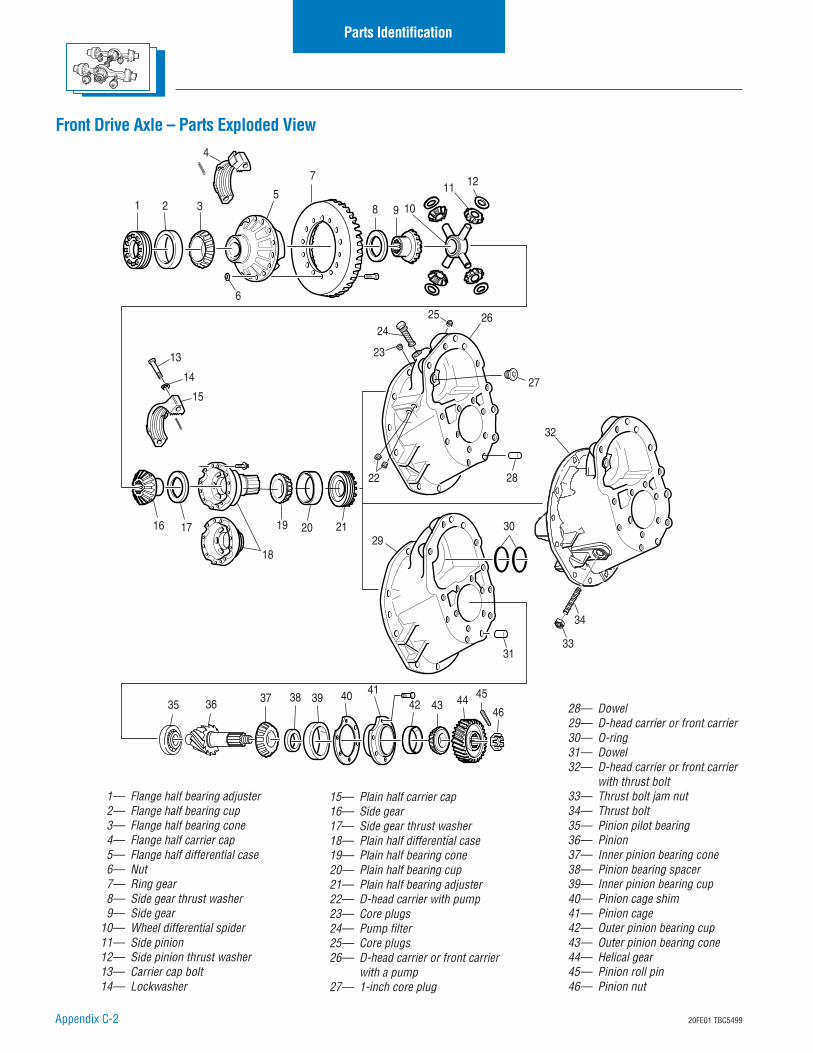
Appendix C-2 20FE01 TBC5499
Parts Identification
Front Drive Axle – Parts Exploded View
1 2 3
7
8 9 10
11
32
125
4
13
14
15
24
23
25 26
22
27
28
16 17
18
19 20 2129
30
3133
34
35 36 37 38 39 40 4142 43 44 45
46
6
1— Flange half bearing adjuster2— Flange half bearing cup3— Flange half bearing cone4— Flange half carrier cap5— Flange half differential case6— Nut7— Ring gear8— Side gear thrust washer9— Side gear
10— Wheel differential spider11— Side pinion12— Side pinion thrust washer13— Carrier cap bolt14— Lockwasher
15— Plain half carrier cap16— Side gear17— Side gear thrust washer18— Plain half differential case19— Plain half bearing cone20— Plain half bearing cup21— Plain half bearing adjuster22— D-head carrier with pump23— Core plugs24— Pump filter25— Core plugs26— D-head carrier or front carrier
with a pump27— 1-inch core plug
28— Dowel29— D-head carrier or front carrier30— O-ring31— Dowel32— D-head carrier or front carrier
with thrust bolt33— Thrust bolt jam nut34— Thrust bolt35— Pinion pilot bearing36— Pinion37— Inner pinion bearing cone38— Pinion bearing spacer39— Inner pinion bearing cup40— Pinion cage shim41— Pinion cage42— Outer pinion bearing cup43— Outer pinion bearing cone44— Helical gear45— Pinion roll pin46— Pinion nut
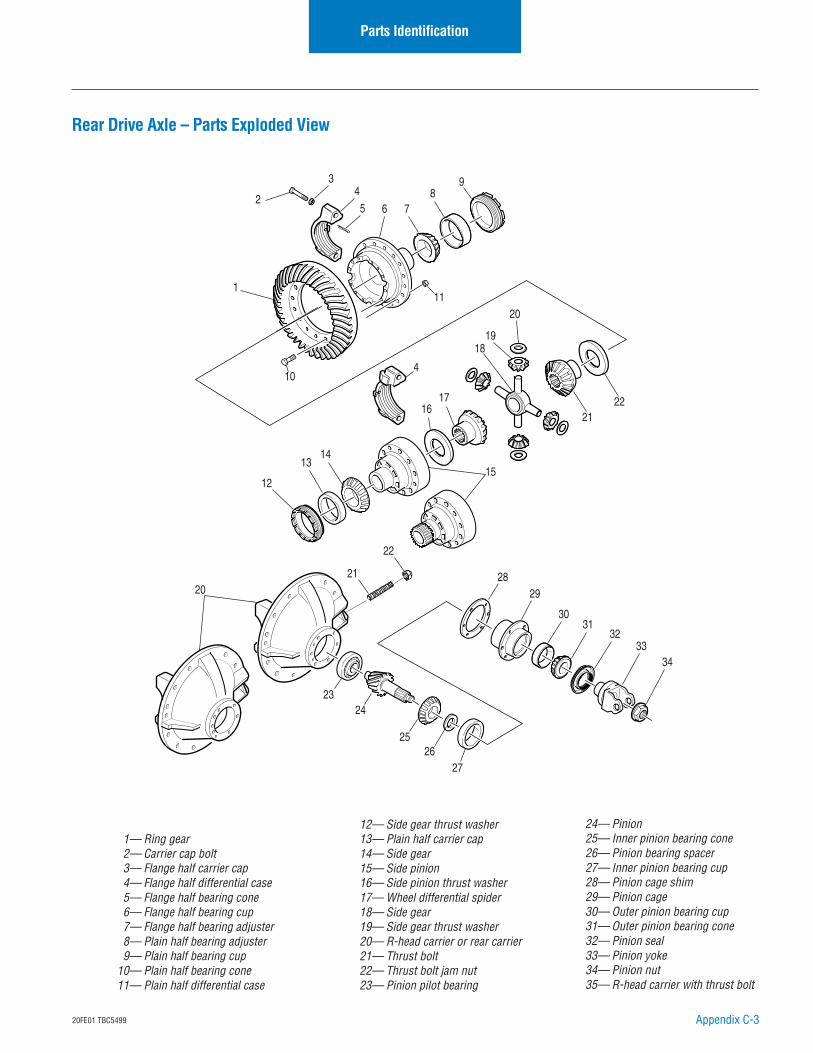
Appendix C-320FE01 TBC5499
Rear Drive Axle – Parts Exploded View
Parts Identification
1— Ring gear2— Carrier cap bolt3— Flange half carrier cap4— Flange half differential case5— Flange half bearing cone6— Flange half bearing cup7— Flange half bearing adjuster8— Plain half bearing adjuster9— Plain half bearing cup
10— Plain half bearing cone11— Plain half differential case
12— Side gear thrust washer13— Plain half carrier cap14— Side gear15— Side pinion16— Side pinion thrust washer17— Wheel differential spider18— Side gear19— Side gear thrust washer20— R-head carrier or rear carrier21— Thrust bolt22— Thrust bolt jam nut23— Pinion pilot bearing
2
18
2122
2021
22
2324
2526
27
2829
3031
3233
34
13
19
4
12
16
8
1
10
11
9
76
45
3
17
14
15
20
24— Pinion25— Inner pinion bearing cone26— Pinion bearing spacer27— Inner pinion bearing cup28— Pinion cage shim29— Pinion cage30— Outer pinion bearing cup31— Outer pinion bearing cone32— Pinion seal33— Pinion yoke34— Pinion nut35— R-head carrier with thrust bolt
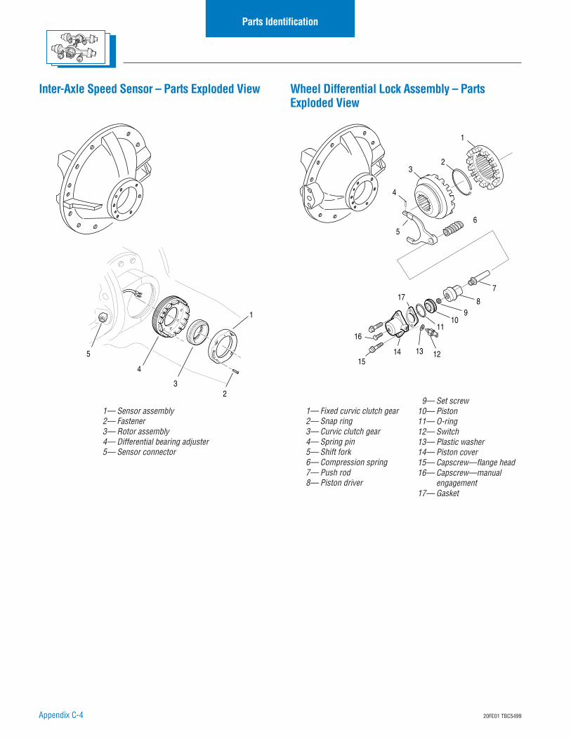
Appendix C-4 20FE01 TBC5499
Parts Identification
Inter-Axle Speed Sensor – Parts Exploded View Wheel Differential Lock Assembly – PartsExploded View
4
5
32
1
15
16
13 12
1110
98
7
65
4
32
1
14
17
1— Sensor assembly2— Fastener3— Rotor assembly4— Differential bearing adjuster5— Sensor connector
1— Fixed curvic clutch gear2— Snap ring3— Curvic clutch gear4— Spring pin5— Shift fork6— Compression spring7— Push rod8— Piston driver
9— Set screw10— Piston11— O-ring12— Switch13— Plastic washer14— Piston cover15— Capscrew—flange head16— Capscrew—manual
engagement17— Gasket
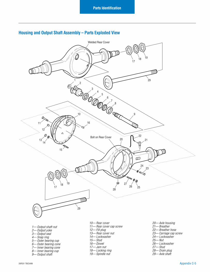
Appendix C-520FE01 TBC5499
1— Output shaft nut2— Output yoke3— Output seal4— Snap ring5— Outer bearing cup6— Outer bearing cone7— Inner bearing cone8— Inner bearing cup9— Output shaft
10— Rear cover11— Rear cover cap screw12— Fill plug13— Rear cover nut14— Lockwasher15— Stud16— Dowel17— Jam nut18— Locking ring19— Spindle nut
Housing and Output Shaft Assembly – Parts Exploded View
20 2122
2423
2726 25
28
29
29
1718 19
Welded Rear Cover
Bolt on Rear Cover
1718 19
12
10
45
67
8
9
12
3
11
1314
15
16
Parts Identification
20— Axle housing21— Breather22— Breather hose23— Carriage cap screw24— Lockwasher25— Nut26— Lockwasher27— Stud28— Drain plug29— Axle shaft
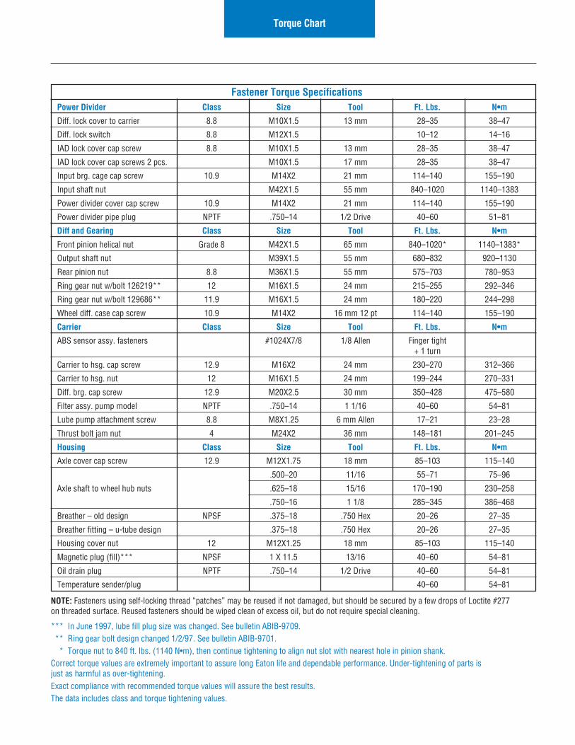
120FE01 TBC5499
Fastener Torque SpecificationsPower Divider Class Size Tool Ft. Lbs. N•m
Diff. lock cover to carrier 8.8 M10X1.5 13 mm 28–35 38–47
Diff. lock switch 8.8 M12X1.5 10–12 14–16
IAD lock cover cap screw 8.8 M10X1.5 13 mm 28–35 38–47
IAD lock cover cap screws 2 pcs. M10X1.5 17 mm 28–35 38–47
Input brg. cage cap screw 10.9 M14X2 21 mm 114–140 155–190
Input shaft nut M42X1.5 55 mm 840–1020 1140–1383
Power divider cover cap screw 10.9 M14X2 21 mm 114–140 155–190
Power divider pipe plug NPTF .750–14 1/2 Drive 40–60 51–81
Diff and Gearing Class Size Tool Ft. Lbs. N•m
Front pinion helical nut Grade 8 M42X1.5 65 mm 840–1020* 1140–1383*
Output shaft nut M39X1.5 55 mm 680–832 920–1130
Rear pinion nut 8.8 M36X1.5 55 mm 575–703 780–953
Ring gear nut w/bolt 126219** 12 M16X1.5 24 mm 215–255 292–346
Ring gear nut w/bolt 129686** 11.9 M16X1.5 24 mm 180–220 244–298
Wheel diff. case cap screw 10.9 M14X2 16 mm 12 pt 114–140 155–190
Carrier Class Size Tool Ft. Lbs. N•m
ABS sensor assy. fasteners #1024X7/8 1/8 Allen Finger tight+ 1 turn
Carrier to hsg. cap screw 12.9 M16X2 24 mm 230–270 312–366
Carrier to hsg. nut 12 M16X1.5 24 mm 199–244 270–331
Diff. brg. cap screw 12.9 M20X2.5 30 mm 350–428 475–580
Filter assy. pump model NPTF .750–14 1 1/16 40–60 54–81
Lube pump attachment screw 8.8 M8X1.25 6 mm Allen 17–21 23–28
Thrust bolt jam nut 4 M24X2 36 mm 148–181 201–245
Housing Class Size Tool Ft. Lbs. N•m
Axle cover cap screw 12.9 M12X1.75 18 mm 85–103 115–140
.500–20 11/16 55–71 75–96
Axle shaft to wheel hub nuts .625–18 15/16 170–190 230–258
.750–16 1 1/8 285–345 386–468
Breather – old design NPSF .375–18 .750 Hex 20–26 27–35
Breather fitting – u-tube design .375–18 .750 Hex 20–26 27–35
Housing cover nut 12 M12X1.25 18 mm 85–103 115–140
Magnetic plug (fill)*** NPSF 1 X 11.5 13/16 40–60 54–81
Oil drain plug NPTF .750–14 1/2 Drive 40–60 54–81
Temperature sender/plug 40–60 54–81
Torque Chart
NOTE: Fasteners using self-locking thread “patches” may be reused if not damaged, but should be secured by a few drops of Loctite #277on threaded surface. Reused fasteners should be wiped clean of excess oil, but do not require special cleaning.
*** In June 1997, lube fill plug size was changed. See bulletin ABIB-9709.** Ring gear bolt design changed 1/2/97. See bulletin ABIB-9701.
* Torque nut to 840 ft. lbs. (1140 N•m), then continue tightening to align nut slot with nearest hole in pinion shank.Correct torque values are extremely important to assure long Eaton life and dependable performance. Under-tightening of parts isjust as harmful as over-tightening.Exact compliance with recommended torque values will assure the best results.The data includes class and torque tightening values.

AXSM-00461/01 PODPrinted in USA
The Roadranger System is an unbeatable combination of the best products from Eaton and Dana: partnering to provide you the most advanced, most trouble-free drivetrain in the industry. And it's backed by the Roadrangers: the most experienced, most expert, most accessible drivetrain consultants in the business.
For spec'ing or service assistance, call 1-800-826-HELP (4357) 24 hours a day, 7 days a week, (Mexico: 001-800-826-HELP (4357)) for more time on the road. Or visit our web site at www.roadranger.com.
Copyright Eaton and Dana Corporation, 2002. EATON AND DANA CORPORATION hereby grants its customers, vendors, or distributors permission to freely copy, reproduce and/or distribute this document in printed format. THIS INFORMATION IS NOT INTENDED FOR SALE OR RE-SALE, AND THIS NOTICE MUST REMAIN ON ALL COPIES.