Embed Size (px)
Citation preview
COMTRAWINGFIVEINST 3710.17A
Enclosure (1)
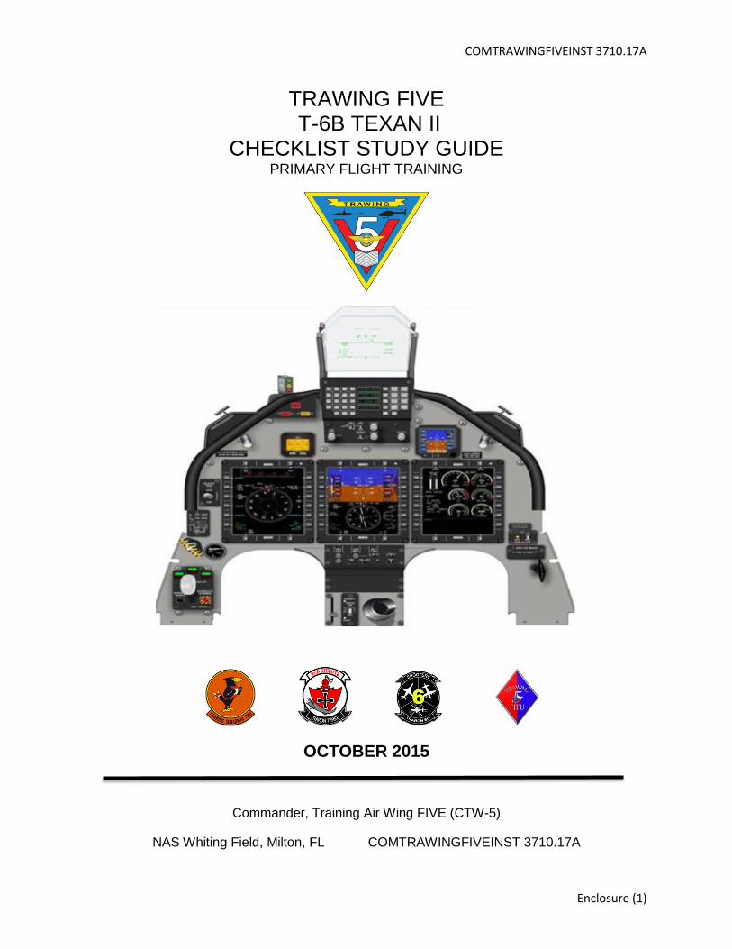
TRAWING FIVE T-6B TEXAN II
CHECKLIST STUDY GUIDE PRIMARY FLIGHT TRAINING
OCTOBER 2015
Commander, Training Air Wing FIVE (CTW-5)
NAS Whiting Field, Milton, FL COMTRAWINGFIVEINST 3710.17A

TRAWINGFIVE Checklist Study Guide COMTRAWINGFIVEINST 3710.17A
2
Training Air Wing FIVE T-6B Checklist Study Guide
General
This checklist guide is for study purposes ONLY. It is NOT to be used during any graded event
within the simulator or aircraft. It is highly recommended to study with this guide and use it as a reference
until you can efficiently use the Quad-fold checklist by itself. The TW-5 Checklist Study Guide reflects
T-6B NATOPS checklist procedures, Contact FTI and TW-5 Fixed-Wing Operating Procedures including
local radio calls.
Changes from the previous checklist guide version have been identified by a black bar located on
the right side of this guide.
Student Naval Aviators (SNA’s) and Instructors Under Training (IUT’s) shall bring the following
items for all Contact/NATOPS scheduled events:
a. Gloves.
b. Kneeboard.
c. T-6B NATOPS.
d. T-6B NATOPS Pocket Checklist (PCL).
e. Contact Flight Training Instruction (FTI).
f. TRAWINGFIVE T-6B In-Flight Guide (IFG).
g. T-6B Quad-fold checklist.
h. SNA’s only: Harness, G-Suit, Helmet, and O2 Mask. A complete strap-in is required for
the C2100 block of training only.
HOW TO USE THIS CHECKLIST GUIDE
This checklist guide is intended to assist SNAs/IUTs in preparation for primary flight training at
TW-5 in the T-6B and to provide checklist standardization and call-outs with all pilots. The checklist
procedures outlined in this guide are to be used on any flight in which the SNA occupies either seat of the
T-6B. It contains the instructions for NORMAL procedures and response phrases necessary to correctly
complete all checklists except for the Before Exterior Inspection, Exterior Inspection, High IOAT at Start
and Before Leaving Aircraft.
The challenge and response format within this guide is widely used in the aviation industry and is
primarily designed to increase Crew Resource Management (CRM) between the SNA/IUT and Instructor
Pilot (IP) as well as ensure each step of the checklist is completed by both crew members. Not every
step requires a dual response however each pilot, regardless of which seat they occupy, must ensure
TRAWINGFIVE Checklist Study Guide COMTRAWINGFIVEINST 3710.17A
3
each step of the checklist has been accomplished. Although it is ultimately the IP’s responsibility to
ensure all checklist items are properly completed, this does not take any responsibility away from the
SNA/IUT. SNAs/IUTs must demonstrate good CRM when challenging their IP if a checklist step has been
executed improperly or inadvertently skipped. When a checklist item requires both crew members to
respond, the SNA/IUT will not proceed to the next item until the IP responds. This will ensure items are
being checked properly by both crew members.
All phrases and terms that are to be verbalized by the crew member running the checklist are
printed in bold within “quotation” marks. When dual concurrence is required, items shown as (BOTH)
within the checklist, the rear cockpit response is highlighted in non-bold italics within “quotation” marks.
SNAs/IUTs are expected to memorize all required crew and radio communications during Contact
simulator events. All response items NOT in quotation marks are merely a check or action and are not to
be verbalized. The SNA/IUT is expected to study and chair-fly with this checklist guide until all actions
and verbalizations can be performed while referencing only the T-6B Quad-fold.
As per the Contact FTI, most checklists are not performed from memory; however, the following
checklist performed during critical phases of flight should be performed from memory: Lineup Check,
After Takeoff, Operations Check, and Before Landing checklist. The Quad-Fold is to be readily available
during the entire flight as a reference to these checklists.
The challenges appear just as they are listed within the T-6 NATOPS. There are many acronyms
used within the checklist. In many cases it is an acceptable practice to verbalize the actual name while
calling out the challenge. For example, BAT Switch = Battery, GEN Switch = Generator, UFCP = Up
Front Control Panel, EMER LDG GR = Emergency Landing Gear, etc.
It is important that both crewmembers remain cognizant of the checklist status as the checklists
are being completed. For this reason, except as noted, the commencement of a checklist is announced
"BEFORE TAKEOFF CHECKLIST. " If a checklist is interrupted, that interruption is announced (i.e.
"Holding the BEFORE TAKEOFF CHECKLIST"). Completion of a checklist is announced (i.e. "BEFORE
TAKEOFF CHECKLIST Complete").
This guide contains NORMAL procedures and communications phrases. Instructions and
communication phrases associated with the EMERGENCY procedures performed during Contact
simulator events are found in the T-6B NATOPS Flight Manual, Contact FTI, and TW-5 Fixed-Wing
Standard Operating Procedures (FWOP).
When executing non-memory checklists, the SNA/IUT will state the CHALLENGE, then perform
the ACTION, then state the RESPONSE. When an ACTION involves a "Check" of the position or setting
of a movable control or switch, the pilot is expected to touch or look at that item to aid in verification of its
TRAWINGFIVE Checklist Study Guide COMTRAWINGFIVEINST 3710.17A
4
position or setting, and if necessary, change its setting or position to make it consistent with the
prescribed RESPONSE.
Only the crewmember in control of the aircraft will physically actuate the landing gear and the
flaps at the appropriate times in the checklist. Unless the SNA/IUT has the controls or has been directed
by the IP, the SNA/IUT will not touch/move the PCL, control stick, rudder pedals/brakes, gear handle or
flap handle.
Refer to Chapter 4 (8-4-1) of the T-6B NATOPS Flight Manual regarding visual hand signals used
when interacting with Lineman. Memorize and practice all ground handling signals.
As you prepare for your Contact simulator events, there are several keys to success. Study with
others in your class to the maximum extent possible and study in a physical reproduction of the cockpit to
the maximum extent possible. While rote memorization of required actions, responses and
communications is imperative, it is not enough to prepare you to perform in the simulator or airplane. The
only way to be smooth, timely and accurate in the completion of checklists is to know and understand
the checklist and also build muscle memory by executing those checklists in the cockpit. Practice in
available OFTs, UTDs or static cockpit trainers.
The Before Exterior Inspection and the Exterior Inspection is not included with this guide but will
be conducted per the PCL or Quad-fold Checklist on the aircraft. Refer to NATOPS chapter 2 for more
information.
When arriving at the aircraft, after opening the canopy but prior to leaning over the cockpit rail,
visually confirm that the Seat Safety Pin is installed, Canopy Fracturing System (CFS) safety pin is
installed, and the Interseat Sequencing System (ISS/ Aft cockpit) is set to SOLO position. Use the
following verbiage after checks complete:
Front Cockpit: “Two Pins In”
Rear Cockpit: “Two Pins In, Solo”
Front Cockpit: “Roger, Solo”
After completing your strap-in (this includes having your kneeboard attached, and gloves on),
turn on the battery, cancel the Master Warning and Master Caution lights and conduct an ICS check
prior to beginning the cockpit checklist.
Front Cockpit: “ICS Check”
Rear Cockpit: “Loud and clear, how me?”
Front Cockpit: “Read you the same”
TRAWINGFIVE Checklist Study Guide COMTRAWINGFIVEINST 3710.17A
5
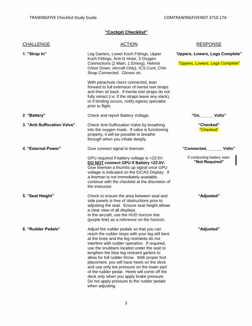
"Cockpit Checklist"
CHALLENGE ACTION RESPONSE 1. “Strap In” Leg Garters, Lower Koch Fittings, Upper
Koch Fittings, Anit-G Hose, 3 Oxygen Connections (2 Main, 1 Emerg), Helmet (Visor Down: Aircraft Only), ICS Cord, Chin Strap Connected. Gloves on. With parachute risers connected, lean forward to full extension of inertia reel straps and then sit back. If inertia reel straps do not fully retract (i.e. if the straps leave any slack), or if binding occurs, notify egress specialist prior to flight.
“Uppers, Lowers, Legs Complete”
“Uppers, Lowers, Legs Complete”
2. “Battery” Check and report Battery Voltage.
"On, _____ Volts"
3. “Anti-Suffocation Valve” Check Anti-Suffocation Valve by breathing into the oxygen mask. If valve is functioning properly, it will be possible to breathe through when you inhale deeply.
“Checked” “Checked”
4. “External Power” Give connect signal to lineman. GPU required if battery voltage is <23.5V. DO NOT connect GPU If Battery <22.0V. Give lineman a thumbs up signal once GPU voltage is indicated on the EICAS Display. If a lineman is not immediately available, continue with the checklist at the discretion of the instructor.
"Connected, ______ Volts"
if conducting battery start:
“Not Required”
5. “Seat Height” Check to ensure the area between seat and side panels is free of obstructions prior to adjusting the seat. Ensure seat height allows a clear view of all displays. In the aircraft, use the HUD horizon line (purple line) as a reference on the horizon.
“Adjusted”
6. “Rudder Pedals” Adjust the rudder pedals so that you can reach the rudder stops with your leg still bent at the knee and the leg restraints do not interfere with rudder operation. If required, use the snubbers located under the seat to lengthen the blue leg restraint garters to allow for full rudder throw. With proper foot placement, you will have heels on the deck and use only toe pressure on the lower part of the rudder pedal. Heels will come off the deck only when you apply brake pressure. Do not apply pressure to the rudder pedals when adjusting.
“Adjusted”
TRAWINGFIVE Checklist Study Guide COMTRAWINGFIVEINST 3710.17A
6
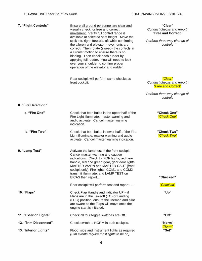
7. “Flight Controls” Ensure all ground personnel are clear and visually check for free and correct movement. Verify full control range is available at selected seat height. Move the stick left, right, forward, aft while confirming the aileron and elevator movements are correct. Then rotate (sweep) the controls in a circular motion to ensure there is no binding. Then check each rudder by applying full rudder. You will need to look over your shoulder to confirm proper operation of the elevator and rudder.
“Clear” Conduct checks and report:
“Free and Correct”
Perform three way change of controls
Rear cockpit will perform same checks as
front cockpit.
“Clear” Conduct checks and report:
“Free and Correct”
Perform three way change of controls
8. “Fire Detection” a. “Fire One” b. “Fire Two”
Check that both bulbs in the upper half of the Fire Light illuminate, master warning and audio activate. Cancel master warning indication. Check that both bulbs in lower half of the Fire Light illuminate, master warning and audio activate. Cancel master warning indication.
“Check One” “Check One”
“Check Two” “Check Two”
9. “Lamp Test” Activate the lamp test in the front cockpit.
Cancel master warning and caution indications. Check for FDR lights, red gear handle, red and green gear, gear door lights, MASTER WARN and MASTER CAUT [front cockpit only], Fire lights, COM1 and COM2 transmit illuminate, and LAMP TEST on EICAS then report…. Rear cockpit will perform test and report…..
“Checked”
“Checked”
10. “Flaps” Check Flap Handle and indicator UP – if Flaps are in the Takeoff (TO) or Landing (LDG) position, ensure the lineman and pilot are aware as the Flaps will move once the engine start is initiated.
“Up”
11. “Exterior Lights” Check all four toggle switches are Off.
“Off”
12. “Trim Disconnect” Check switch to NORM in both cockpits.
“Norm” “Norm”
13. “Interior Lights” Flood, side and instrument lights as required (Sim events require most lights to be on).
“Set”

TRAWINGFIVE Checklist Study Guide COMTRAWINGFIVEINST 3710.17A
7
14. “Trim Aid” Check switch is Off.
“Off”
15. “Trim Operation” Move Aileron Trim left, then right returning trim indicator back to green.
Move Elevator Tim up then down returning trim indicator back to green. Move Rudder Trim right, then left leaving the indicator to the left of the green at approximately the 12 o’clock position. (This is a setup to check TAD operation in the Before Taxi checklist).
“Checked” Rear Cockpit will also check trim and
report:
“Checked”
16. “Emergency Landing Gear Handle”
Ensure full forward (in).
“Check Stowed”
17. “Clock” Ensure the digital clock is in either the Local
Time or Elapsed Time function as required.
“Set”
18 “Up Front Control Panel” a. HUD TEXT/FPM UNCAGE/CAGE
b. LGT NIGHT/DAY/AUTO HUD
c. MFD/UFCP REPEAT/ NORM d. LGT-HUD e. LGT-UFCP
Check Switches in appropriate position. (All switches in the DOWN position). Check CAGE. Check AUTO HUD. Check NORM. As Required. As Required.
“Set”
19. “Audio Panel” Check VOX button is out and turn to the one o’clock position, COM1 and COM2 buttons should be IN until time for radio usage. The one o’clock position is a good starting point for audio controls. Ensure that DME, NAV and MKR switches are IN and EMR/NRM toggle switch is set to NRM. Adjust interphone and headphone volume as desired.
“Set”
20. “Defog” Check Defog switch OFF.
“Off”
21. “ELT” Check switch ARM.
“Arm”
22. “Parking Brake” Set the parking brake by applying the toe
brakes while simultaneously pulling and
turning the parking brake lever 90º
clockwise. Pump the brakes several times
in case pressure from the master cylinder
has bled off. This will prevent the aircraft
from creeping forward on engine startup. Do
not touch the parking brake handle shaft
when actuating or releasing the parking
“Reset”
TRAWINGFIVE Checklist Study Guide COMTRAWINGFIVEINST 3710.17A
8
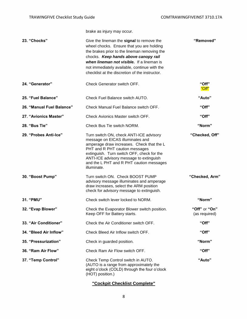
brake as injury may occur.
23. “Chocks” Give the lineman the signal to remove the
wheel chocks. Ensure that you are holding
the brakes prior to the lineman removing the
chocks. Keep hands above canopy rail
when lineman not visible. If a lineman is
not immediately available, continue with the
checklist at the discretion of the instructor.
“Removed”
24. “Generator” Check Generator switch OFF. “Off” “Off”
25. “Fuel Balance” Check Fuel Balance switch AUTO.
“Auto”
26. “Manual Fuel Balance” Check Manual Fuel Balance switch OFF.
“Off”
27. “Avionics Master” Check Avionics Master switch OFF.
“Off”
28. “Bus Tie” Check Bus Tie switch NORM.
“Norm”
29. “Probes Anti-Ice” Turn switch ON, check ANTI-ICE advisory message on EICAS illuminates and amperage draw increases. Check that the L PHT and R PHT caution messages extinguish. Turn switch OFF, check for the ANTI-ICE advisory message to extinguish and the L PHT and R PHT caution messages illuminate.
“Checked, Off”
30. “Boost Pump” Turn switch ON. Check BOOST PUMP advisory message illuminates and amperage draw increases, select the ARM position check for advisory message to extinguish.
“Checked, Arm”
31. “PMU” Check switch lever locked to NORM.
“Norm”
32. “Evap Blower” Check the Evaporator Blower switch position. Keep OFF for Battery starts.
“Off” or “On” (as required)
33. “Air Conditioner” Check the Air Conditioner switch OFF.
“Off”
34. “Bleed Air Inflow” Check Bleed Air Inflow switch OFF.
“Off”
35. “Pressurization” Check in guarded position.
“Norm”
36. “Ram Air Flow” Check Ram Air Flow switch OFF.
“Off”
37. “Temp Control” Check Temp Control switch in AUTO. (AUTO is a range from approximately the eight o’clock (COLD) through the four o’clock (HOT) position.)
“Auto”
"Cockpit Checklist Complete"
TRAWINGFIVE Checklist Study Guide COMTRAWINGFIVEINST 3710.17A
9
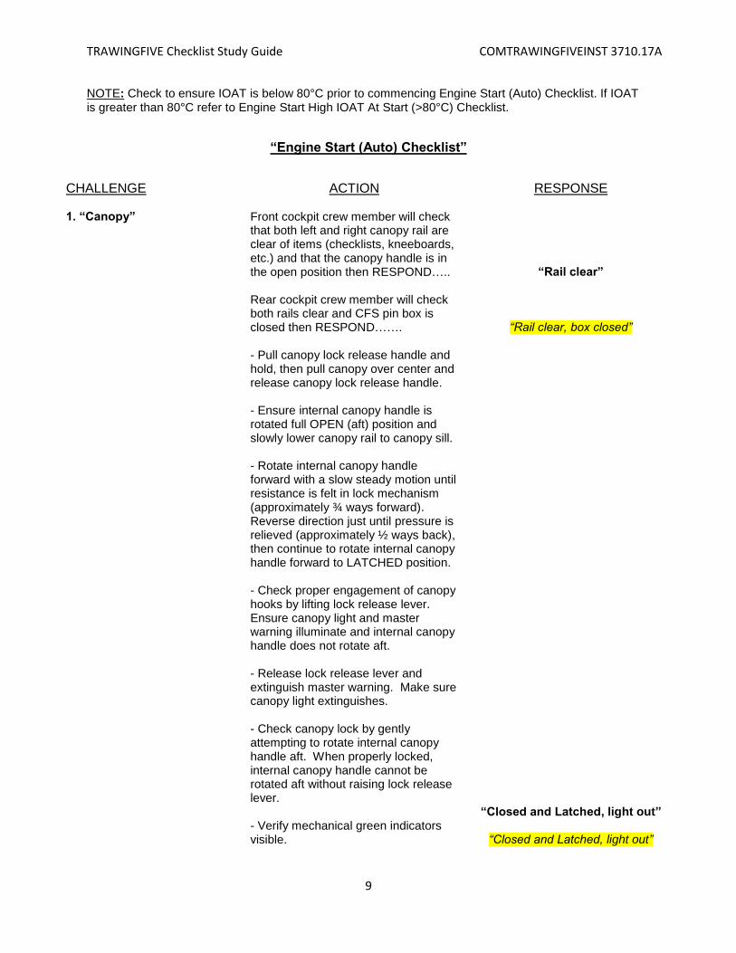
NOTE: Check to ensure IOAT is below 80°C prior to commencing Engine Start (Auto) Checklist. If IOAT is greater than 80°C refer to Engine Start High IOAT At Start (>80°C) Checklist.
“Engine Start (Auto) Checklist”
CHALLENGE ACTION RESPONSE 1. “Canopy” Front cockpit crew member will check
that both left and right canopy rail are clear of items (checklists, kneeboards, etc.) and that the canopy handle is in the open position then RESPOND….. Rear cockpit crew member will check both rails clear and CFS pin box is closed then RESPOND…….
“Rail clear”
“Rail clear, box closed”
- Pull canopy lock release handle and hold, then pull canopy over center and release canopy lock release handle. - Ensure internal canopy handle is rotated full OPEN (aft) position and slowly lower canopy rail to canopy sill. - Rotate internal canopy handle forward with a slow steady motion until resistance is felt in lock mechanism (approximately ¾ ways forward). Reverse direction just until pressure is relieved (approximately ½ ways back), then continue to rotate internal canopy handle forward to LATCHED position. - Check proper engagement of canopy hooks by lifting lock release lever. Ensure canopy light and master warning illuminate and internal canopy handle does not rotate aft. - Release lock release lever and extinguish master warning. Make sure canopy light extinguishes. - Check canopy lock by gently attempting to rotate internal canopy handle aft. When properly locked, internal canopy handle cannot be rotated aft without raising lock release lever. - Verify mechanical green indicators visible.
“Closed and Latched, light out”
“Closed and Latched, light out”

TRAWINGFIVE Checklist Study Guide COMTRAWINGFIVEINST 3710.17A
10
Ensure minimum adequate canopy/helmet clearance by placing closed fist on top of helmet when adjusting seat height. Excessive seat height (helmet above canopy breakers) can result in fatal injury upon ejection.
2. “Navigation and Anti- Collision Lights”
Turn navigation and anti-collision lights ON (anti-collision lights off at night in the line area).
“On”
3. “PMU Fail / PMU Status Messages”
Check PMU fail warning and status caution messages are extinguished. If not, reset PMU by turning PMU to OFF then back to NORM.
“Extinguished”
4. “PCL” Smoothly advance to Start Ready position and ensure the ST READY advisory message remains illuminated for three seconds. If message goes out, do not start. Pull PCL back to cutoff and repeat step. Recommended method: Once ST READY advisory message illuminates, hover hand above PCL (to prevent inadvertent movement, but in position to abort start if required).
“Start Ready”
5. “Propeller Area” Check left, right, and forward of the propeller area clear and signal the lineman ready for start. The lineman will act as a fire watch.
“Clear”
6. “Starter Switch” Move starter switch to the
AUTO/RESET position and release. “Auto / Reset”
7. “Engine Start” Monitor engine instruments for normal
indications and the lineman during the start. Hydraulic pressure should climb to the normal range followed by N1 rotation. Indication of Fuel Flow should follow, with light-off occurring shortly thereafter. Call out “Light-off” with initial rise of ITT. ITT should rise, peaking twice. Oil pressure should rise as well and N1 will accelerate to 60-61%. Call out “N1 60%” as appropriate. Ensure ST READY advisory message remains illuminated (NOTE: ST READY message will change position on the EICAS during start).
(Monitor)
“Light-off...”
“N1 60%”
TRAWINGFIVE Checklist Study Guide COMTRAWINGFIVEINST 3710.17A
11
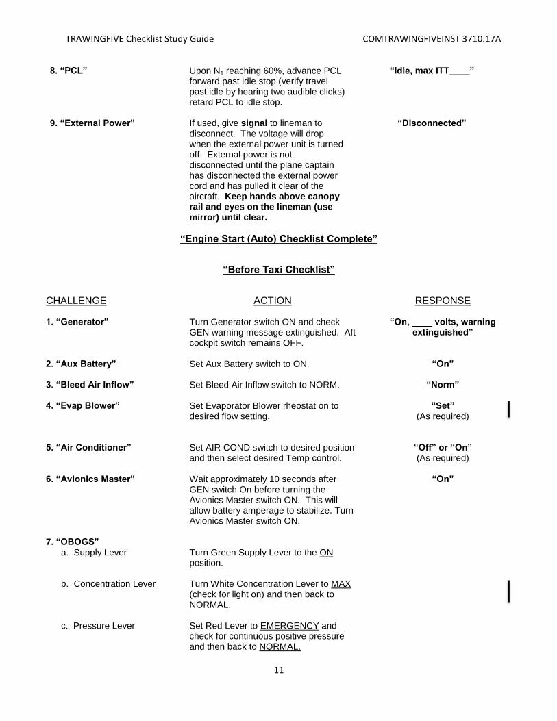
8. “PCL” Upon N1 reaching 60%, advance PCL forward past idle stop (verify travel past idle by hearing two audible clicks) retard PCL to idle stop.
“Idle, max ITT____”
9. “External Power” If used, give signal to lineman to
disconnect. The voltage will drop when the external power unit is turned off. External power is not disconnected until the plane captain has disconnected the external power cord and has pulled it clear of the aircraft. Keep hands above canopy rail and eyes on the lineman (use mirror) until clear.
“Disconnected”
“Engine Start (Auto) Checklist Complete”
“Before Taxi Checklist”
CHALLENGE ACTION RESPONSE 1. “Generator” Turn Generator switch ON and check
GEN warning message extinguished. Aft cockpit switch remains OFF.
“On, ____ volts, warning extinguished”
2. “Aux Battery” Set Aux Battery switch to ON. “On” 3. “Bleed Air Inflow” Set Bleed Air Inflow switch to NORM. “Norm” 4. “Evap Blower” Set Evaporator Blower rheostat on to
desired flow setting.
“Set” (As required)
5. “Air Conditioner” Set AIR COND switch to desired position
and then select desired Temp control. “Off” or “On” (As required)
6. “Avionics Master” Wait approximately 10 seconds after
GEN switch On before turning the Avionics Master switch ON. This will allow battery amperage to stabilize. Turn Avionics Master switch ON.
“On”
7. “OBOGS” a. Supply Lever b. Concentration Lever c. Pressure Lever
Turn Green Supply Lever to the ON position. Turn White Concentration Lever to MAX (check for light on) and then back to NORMAL. Set Red Lever to EMERGENCY and check for continuous positive pressure and then back to NORMAL.
TRAWINGFIVE Checklist Study Guide COMTRAWINGFIVEINST 3710.17A
12
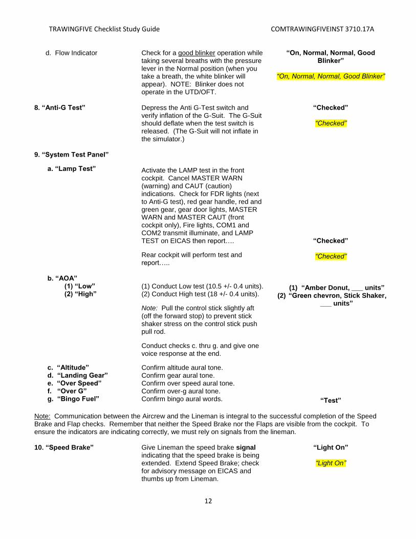
d. Flow Indicator Check for a good blinker operation while taking several breaths with the pressure lever in the Normal position (when you take a breath, the white blinker will appear). NOTE: Blinker does not operate in the UTD/OFT.
“On, Normal, Normal, Good Blinker”
“On, Normal, Normal, Good Blinker”
8. “Anti-G Test” Depress the Anti G-Test switch and
verify inflation of the G-Suit. The G-Suit should deflate when the test switch is released. (The G-Suit will not inflate in the simulator.)
“Checked”
“Checked”
9. “System Test Panel”
a. “Lamp Test” b. “AOA” (1) “Low” (2) “High”
Activate the LAMP test in the front cockpit. Cancel MASTER WARN (warning) and CAUT (caution) indications. Check for FDR lights (next to Anti-G test), red gear handle, red and green gear, gear door lights, MASTER WARN and MASTER CAUT (front cockpit only), Fire lights, COM1 and COM2 transmit illuminate, and LAMP TEST on EICAS then report….
Rear cockpit will perform test and report….. (1) Conduct Low test (10.5 +/- 0.4 units). (2) Conduct High test (18 +/- 0.4 units).
Note: Pull the control stick slightly aft (off the forward stop) to prevent stick shaker stress on the control stick push pull rod.
“Checked”
“Checked”
(1) “Amber Donut, ___ units”
(2) “Green chevron, Stick Shaker, ___ units”
Conduct checks c. thru g. and give one voice response at the end.
c. “Altitude” d. “Landing Gear” e. “Over Speed” f. “Over G” g. “Bingo Fuel”
Confirm altitude aural tone. Confirm gear aural tone. Confirm over speed aural tone. Confirm over-g aural tone. Confirm bingo aural words.
“Test” Note: Communication between the Aircrew and the Lineman is integral to the successful completion of the Speed Brake and Flap checks. Remember that neither the Speed Brake nor the Flaps are visible from the cockpit. To ensure the indicators are indicating correctly, we must rely on signals from the lineman. 10. “Speed Brake” Give Lineman the speed brake signal
indicating that the speed brake is being extended. Extend Speed Brake; check for advisory message on EICAS and thumbs up from Lineman.
“Light On”
“Light On”
TRAWINGFIVE Checklist Study Guide COMTRAWINGFIVEINST 3710.17A
13
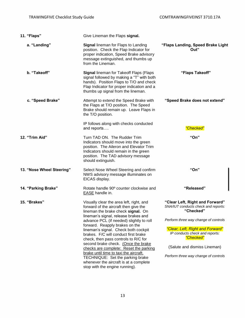
11. “Flaps” a. “Landing” b. “Takeoff”
c. “Speed Brake”
Give Lineman the Flaps signal. Signal lineman for Flaps to Landing position. Check the Flap Indicator for proper indication, Speed Brake advisory message extinguished, and thumbs up from the Lineman. Signal lineman for Takeoff Flaps (Flaps signal followed by making a “T” with both hands). Position Flaps to T/O and check Flap Indicator for proper indication and a thumbs up signal from the lineman. Attempt to extend the Speed Brake with the Flaps at T/O position. The Speed Brake should remain up. Leave Flaps in the T/O position. IP follows along with checks conducted and reports….
“Flaps Landing, Speed Brake Light Out”
“Flaps Takeoff”
“Speed Brake does not extend”
“Checked” 12. “Trim Aid” Turn TAD ON. The Rudder Trim
Indicators should move into the green position. The Aileron and Elevator Trim Indicators should remain in the green position. The TAD advisory message should extinguish.
“On”
13. “Nose Wheel Steering” Select Nose Wheel Steering and confirm
NWS advisory message illuminates on EICAS display.
“On”
14. “Parking Brake” Rotate handle 90º counter clockwise and EASE handle in.
“Released”
15. “Brakes” Visually clear the area left, right, and
forward of the aircraft then give the lineman the brake check signal. On lineman’s signal, release brakes and advance PCL (if needed) slightly to roll forward. Reapply brakes on the lineman’s signal. Check both cockpit brakes. F/C will conduct first brake check, then pass controls to R/C for second brake check. (Once the brake checks are complete: Reset the parking brake until time to taxi the aircraft. TECHNIQUE: Set the parking brake whenever the aircraft is at a complete stop with the engine running).
“Clear Left, Right and Forward” SNA/IUT conducts check and reports:
“Checked”
Perform three way change of controls
“Clear, Left, Right and Forward”
IP conducts check and reports:
“Checked”
(Salute and dismiss Lineman)
Perform three way change of controls
TRAWINGFIVE Checklist Study Guide COMTRAWINGFIVEINST 3710.17A
14
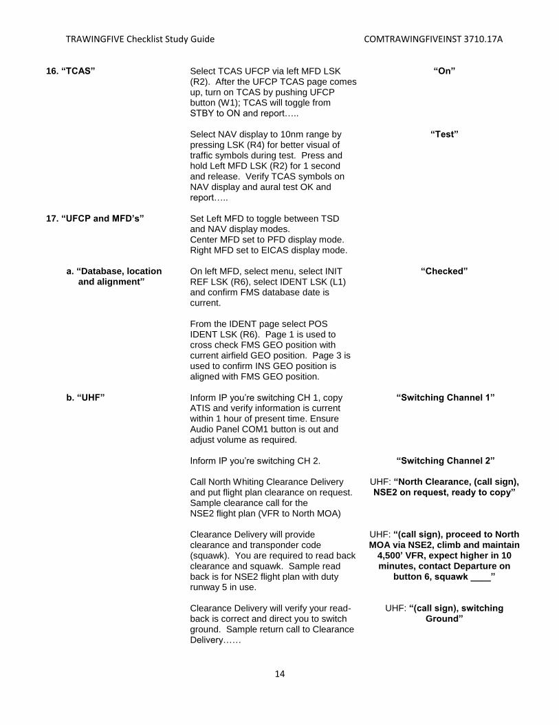
16. “TCAS” Select TCAS UFCP via left MFD LSK (R2). After the UFCP TCAS page comes up, turn on TCAS by pushing UFCP button (W1); TCAS will toggle from STBY to ON and report….. Select NAV display to 10nm range by pressing LSK (R4) for better visual of traffic symbols during test. Press and hold Left MFD LSK (R2) for 1 second and release. Verify TCAS symbols on NAV display and aural test OK and report…..
“On”
“Test”
17. “UFCP and MFD’s” a. “Database, location
and alignment”
Set Left MFD to toggle between TSD and NAV display modes. Center MFD set to PFD display mode. Right MFD set to EICAS display mode. On left MFD, select menu, select INIT REF LSK (R6), select IDENT LSK (L1) and confirm FMS database date is current. From the IDENT page select POS IDENT LSK (R6). Page 1 is used to cross check FMS GEO position with current airfield GEO position. Page 3 is used to confirm INS GEO position is aligned with FMS GEO position.
“Checked”
b. “UHF”
Inform IP you’re switching CH 1, copy ATIS and verify information is current within 1 hour of present time. Ensure Audio Panel COM1 button is out and adjust volume as required. Inform IP you’re switching CH 2. Call North Whiting Clearance Delivery and put flight plan clearance on request. Sample clearance call for the NSE2 flight plan (VFR to North MOA) Clearance Delivery will provide clearance and transponder code (squawk). You are required to read back clearance and squawk. Sample read back is for NSE2 flight plan with duty runway 5 in use. Clearance Delivery will verify your read-back is correct and direct you to switch ground. Sample return call to Clearance Delivery……
“Switching Channel 1”
“Switching Channel 2”
UHF: “North Clearance, (call sign), NSE2 on request, ready to copy”
UHF: “(call sign), proceed to North MOA via NSE2, climb and maintain
4,500’ VFR, expect higher in 10 minutes, contact Departure on
button 6, squawk ____”
UHF: “(call sign), switching Ground”

TRAWINGFIVE Checklist Study Guide COMTRAWINGFIVEINST 3710.17A
15
Inform IP you’re switching to CH 3.
“Switching Channel 3”
c. “VHF” Set desired frequency of intended use. For example, if heading to the NMOA, use JAX Center on CH 16 or place on KNSE Tower CH 4.
“Set to ____”
d. “VOR” Set to desired frequency. For example
CH 1 is 112.3, which is the paired frequency for the NSE TACAN.
“____Set”
e. “Transponder” Set appropriate code from flight
clearance and ensure the transponder is set to “SBY.”
“Standby”
f. “FMS” This is a minimum recommended setup
for a typical Contact flight. Subsequent setup will be dictated by type of sortie being flown. -PFD source set to VOR. -Bearing pointer #1 (green) set to VOR. -Bearing pointer #2 (cyan) set to FMS. -Heading bug set to departure heading. -CDI course set to runway heading. -Left MFD set to view NAV display with range set to 5 nm. Disable SUA alerts.
“Set”
g. “Alt, G, Speed, Fuel Flags”
Set altitude to first expected level off. Zero the G meter. Set speed and fuel flags (Joker/Bingo) as required.
“Set”
18. “Flight Instruments” Check pitch, roll and heading indications,
and no red X’s. (A failed display will appear as a red X. Report any abnormal indication).
“Checked”
“Checked”
19. “Altimeters” Set the local altimeter in the PFD and the
BFI in both cockpits. Check to ensure the altimeter readout is within 75’ of local field elevation and within 75’ of each other. (NSE field elevation is 199’ MSL).
“_____ set and checked twice”
“_____ set and checked twice”
20. “EICAS Display” Check to ensure the Master Warning and
Caution Lights are extinguished and CAS Display is clear of all malfunctions. Verbalize any warning, caution, or advisory messages. You should only have L PHT and R PHT INOP cautions and NWS ON.
“Checked, (Report what is displayed)”
“Checked”
21. “Landing and Taxi Lights” Turn Landing and Taxi Lights ON. “On”
“Before Taxi Checklist Complete”
TRAWINGFIVE Checklist Study Guide COMTRAWINGFIVEINST 3710.17A
16
ACTION RESPONSE
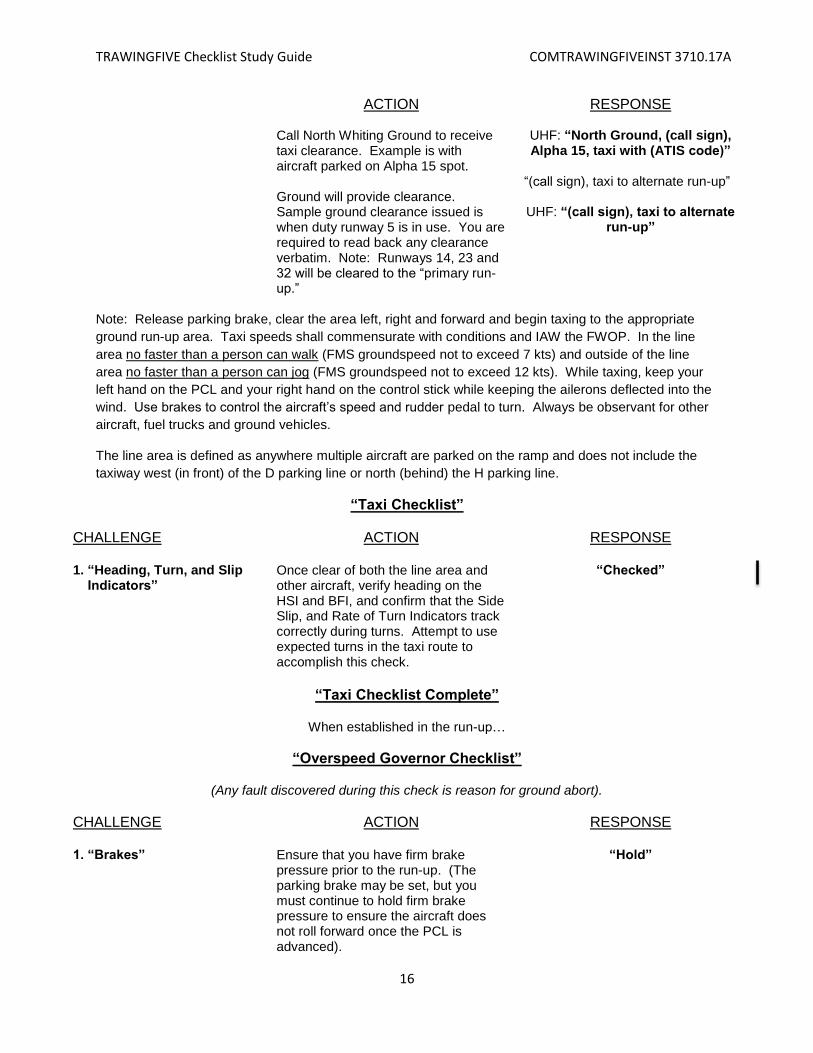
Call North Whiting Ground to receive taxi clearance. Example is with aircraft parked on Alpha 15 spot. Ground will provide clearance. Sample ground clearance issued is when duty runway 5 is in use. You are required to read back any clearance verbatim. Note: Runways 14, 23 and 32 will be cleared to the “primary run-up.”
UHF: “North Ground, (call sign), Alpha 15, taxi with (ATIS code)”
“(call sign), taxi to alternate run-up”
UHF: “(call sign), taxi to alternate
run-up”
Note: Release parking brake, clear the area left, right and forward and begin taxing to the appropriate
ground run-up area. Taxi speeds shall commensurate with conditions and IAW the FWOP. In the line
area no faster than a person can walk (FMS groundspeed not to exceed 7 kts) and outside of the line
area no faster than a person can jog (FMS groundspeed not to exceed 12 kts). While taxing, keep your
left hand on the PCL and your right hand on the control stick while keeping the ailerons deflected into the
wind. Use brakes to control the aircraft’s speed and rudder pedal to turn. Always be observant for other
aircraft, fuel trucks and ground vehicles.
The line area is defined as anywhere multiple aircraft are parked on the ramp and does not include the
taxiway west (in front) of the D parking line or north (behind) the H parking line.
“Taxi Checklist”
CHALLENGE ACTION RESPONSE 1. “Heading, Turn, and Slip Indicators”
Once clear of both the line area and other aircraft, verify heading on the HSI and BFI, and confirm that the Side Slip, and Rate of Turn Indicators track correctly during turns. Attempt to use expected turns in the taxi route to accomplish this check.
“Checked”
“Taxi Checklist Complete”
When established in the run-up…
“Overspeed Governor Checklist”
(Any fault discovered during this check is reason for ground abort).
CHALLENGE ACTION RESPONSE 1. “Brakes” Ensure that you have firm brake
pressure prior to the run-up. (The parking brake may be set, but you must continue to hold firm brake pressure to ensure the aircraft does not roll forward once the PCL is advanced).
“Hold”
TRAWINGFIVE Checklist Study Guide COMTRAWINGFIVEINST 3710.17A
17
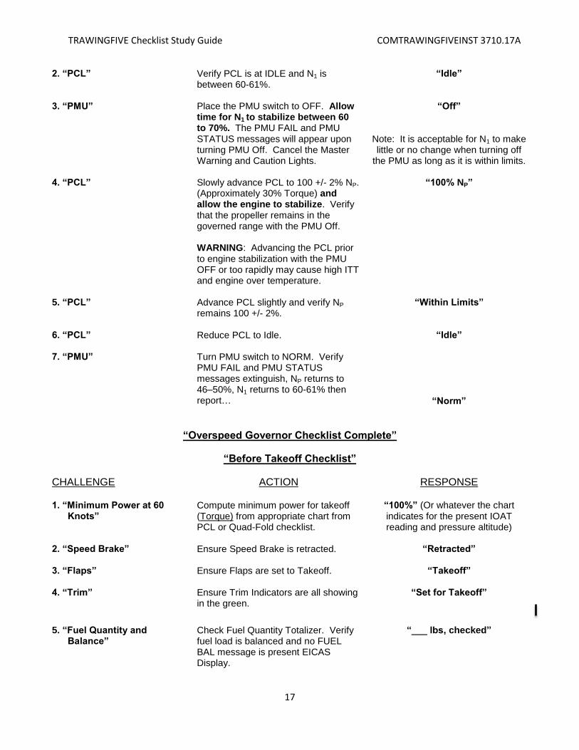
2. “PCL” Verify PCL is at IDLE and N1 is between 60-61%.
“Idle”
3. “PMU” Place the PMU switch to OFF. Allow
time for N1 to stabilize between 60 to 70%. The PMU FAIL and PMU STATUS messages will appear upon turning PMU Off. Cancel the Master Warning and Caution Lights.
“Off”
Note: It is acceptable for N1 to make little or no change when turning off
the PMU as long as it is within limits. 4. “PCL” Slowly advance PCL to 100 +/- 2% NP.
(Approximately 30% Torque) and allow the engine to stabilize. Verify that the propeller remains in the governed range with the PMU Off. WARNING: Advancing the PCL prior to engine stabilization with the PMU OFF or too rapidly may cause high ITT and engine over temperature.
“100% NP”
5. “PCL” Advance PCL slightly and verify NP
remains 100 +/- 2%. “Within Limits”
6. “PCL” Reduce PCL to Idle. “Idle” 7. “PMU” Turn PMU switch to NORM. Verify
PMU FAIL and PMU STATUS messages extinguish, NP returns to 46–50%, N1 returns to 60-61% then report…
“Norm”
“Overspeed Governor Checklist Complete”
“Before Takeoff Checklist”
CHALLENGE ACTION RESPONSE 1. “Minimum Power at 60 Knots”
Compute minimum power for takeoff (Torque) from appropriate chart from PCL or Quad-Fold checklist.
“100%” (Or whatever the chart indicates for the present IOAT reading and pressure altitude)
2. “Speed Brake” Ensure Speed Brake is retracted. “Retracted” 3. “Flaps” Ensure Flaps are set to Takeoff.
“Takeoff”
4. “Trim” Ensure Trim Indicators are all showing in the green.
“Set for Takeoff”
5. “Fuel Quantity and Balance”
Check Fuel Quantity Totalizer. Verify fuel load is balanced and no FUEL BAL message is present EICAS Display.
“___ lbs, checked”

TRAWINGFIVE Checklist Study Guide COMTRAWINGFIVEINST 3710.17A
18
6. “Engine Instruments” Check all engine instruments on the
EICAS Display are within normal operating limits.
“Checked”
7. “DVR Control” Not used at this time. “Not Required” 8. “Amps” Verify +50 amps or less. “Less than 50” 9. “Defog” Ensure DEFOG switch is OFF. “Off” 10. “Oxygen Mask” Place oxygen mask on and adjust as
necessary. “On and secure” “On and secure”
11. “Seat Safety Pin” Prior to pulling the ejection seat safety
pin, ensure the safety streamer is free and clear of the ejection seat handle. With the “two-hand method” (one hand on the streamer and one on the pin) remove the Seat Safety Pin and stow in the canopy locking handle. If seat safety pin is dropped, refer to the IFG for pin recovery procedures.
“Removed and Stowed” “Removed and Stowed”
12. “ISS Mode Selector” Verify ISS Mode Selector lever is
locked in the desired detent. (Rear cockpit will position ISS to desired detent and report). Note: Current TW-5 guidance directs the use of SOLO position until further notice.
“Solo” or “Both” (As required)
“Roger Solo” or “Roger Both”
“Before Takeoff Checklist Complete”
ACTION RESPONSE
Inform IP you’re switching to squadron base to report outbound. VT-2 (Blackbird): CH 20 VT3 (Redmax): CH 30 VT6 (Shooter): CH 60 FITU (Texan): CH 50
“Switching Base”
UHF: “(Base name) base, (call
sign), outbound”
Switch to CH 3. “Switching channel 3” Call ground for further taxi clearance.
Ground will provide further clearance to taxi to active runway. Read back verbatim all runways, hold short and runway crossing clearances.
UHF: “North Ground, (call sign), alternate run-up, further taxi”
“(call sign), runway five, taxi via
Alpha”
UHF: “(call sign), taxi runway five via Alpha”
TRAWINGFIVE Checklist Study Guide COMTRAWINGFIVEINST 3710.17A
19
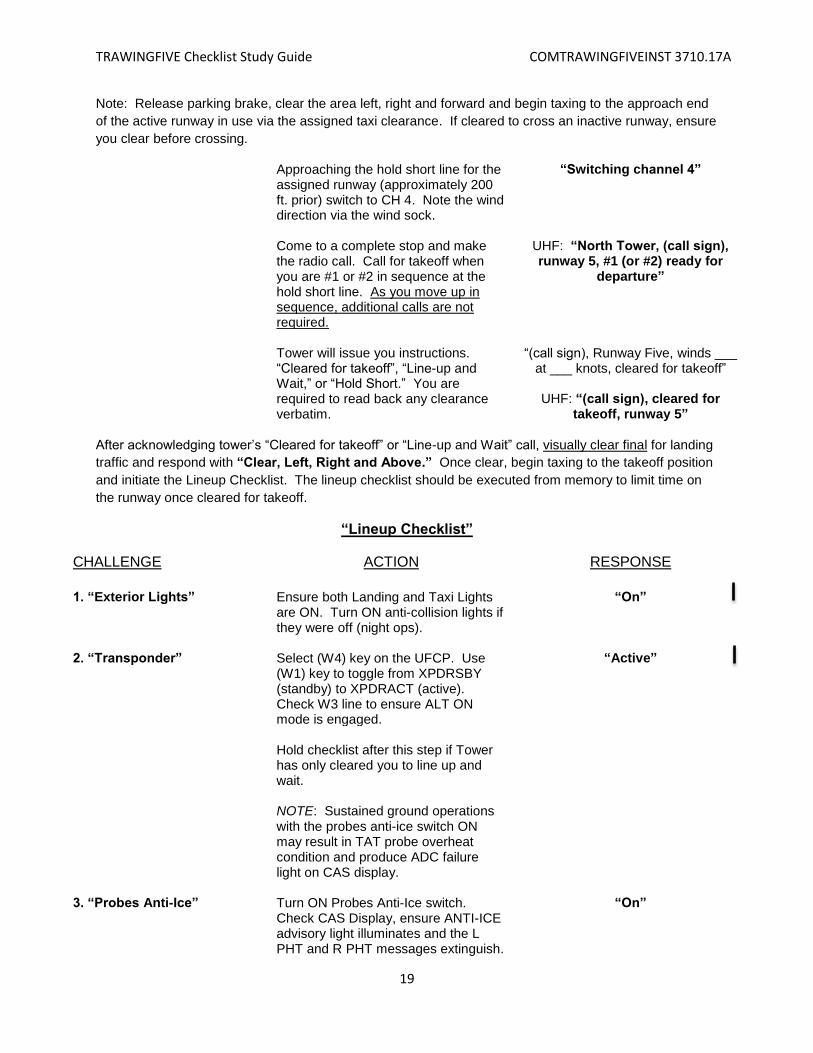
Note: Release parking brake, clear the area left, right and forward and begin taxing to the approach end
of the active runway in use via the assigned taxi clearance. If cleared to cross an inactive runway, ensure
you clear before crossing.
Approaching the hold short line for the assigned runway (approximately 200 ft. prior) switch to CH 4. Note the wind direction via the wind sock.
“Switching channel 4”
Come to a complete stop and make
the radio call. Call for takeoff when you are #1 or #2 in sequence at the hold short line. As you move up in sequence, additional calls are not required.
UHF: “North Tower, (call sign), runway 5, #1 (or #2) ready for
departure”
Tower will issue you instructions.
“Cleared for takeoff”, “Line-up and Wait,” or “Hold Short.” You are required to read back any clearance verbatim.
“(call sign), Runway Five, winds ___ at ___ knots, cleared for takeoff”
UHF: “(call sign), cleared for
takeoff, runway 5”
After acknowledging tower’s “Cleared for takeoff” or “Line-up and Wait” call, visually clear final for landing
traffic and respond with “Clear, Left, Right and Above.” Once clear, begin taxing to the takeoff position
and initiate the Lineup Checklist. The lineup checklist should be executed from memory to limit time on
the runway once cleared for takeoff.
“Lineup Checklist”
CHALLENGE ACTION RESPONSE
1. “Exterior Lights” Ensure both Landing and Taxi Lights are ON. Turn ON anti-collision lights if they were off (night ops).
“On”
2. “Transponder” Select (W4) key on the UFCP. Use
(W1) key to toggle from XPDRSBY (standby) to XPDRACT (active). Check W3 line to ensure ALT ON mode is engaged.
“Active”
Hold checklist after this step if Tower has only cleared you to line up and wait. NOTE: Sustained ground operations with the probes anti-ice switch ON may result in TAT probe overheat condition and produce ADC failure light on CAS display.
3. “Probes Anti-Ice” Turn ON Probes Anti-Ice switch. Check CAS Display, ensure ANTI-ICE advisory light illuminates and the L PHT and R PHT messages extinguish.
“On”

TRAWINGFIVE Checklist Study Guide COMTRAWINGFIVEINST 3710.17A
20
4. “Nose Wheel Steering” Once aligned with runway centerline, roll slightly forward to ensure Nose Wheel is straight, come to a stop using even braking and hold brakes. Deactivate Nose Wheel Steering. Verify NWS Light on CAS Display extinguishes.
“Off”
5. “EICAS Display” Check EICAS Display. Ensure there
are no warning or caution messages illuminated.
“Checked” “Checked”
“Lineup Checklist Complete”
ACTION RESPONSE
Verbally call out right to left or left to right crosswinds as reported by tower. Verify with windsock, if available.
“Winds are right to left or left to right, cleared for takeoff”
With takeoff clearance and properly aligned on the runway with Lineup checklist complete, hold brakes, bring the elevator to the neutral position and position the ailerons into the wind: smoothly increase torque to ~30% and check engine instruments and report….
“Instruments checked”
Rear cockpit will also report…. “Instruments checked”
Perform takeoff roll per Contact FTI. When aircraft speed reaches 60 KIAS, verify TORQUE indication is at or above what you computed for minimum power at 60 KIAS and report….. Once at 85 knots (or adjusted gust factor speed), report and execute rotation IAW Contact FTI.
“60 knots, ___% torque”
“85 knots, rotate”
Conduct takeoff procedures IAW Contact FTI and FWOP procedures.

TRAWINGFIVE Checklist Study Guide COMTRAWINGFIVEINST 3710.17A
21
Note: Step one commences the After Takeoff Checklist. Do not call for the After Takeoff Checklist for
the initiation or completion as you do for all other checklists. Follow the model below:
After Takeoff Checklist
ACTION RESPONSE Once aircraft is airborne and a safe
landing can no longer be made:
1. Gear Check for two positive rates of climb
indicated on the Altimeter, the VSI or visually.
“Two positive rates, Gear”
2. Flaps
Verify airspeed is above 110 KIAS and raise the flaps and then report… Verify gear position lights and gear handle light have extinguished and the flap indicator indicates up prior to 150 KIAS; then report……… Rear cockpit verifies proper up indications and reports…. CLEAR-CLICK-CLIMB-CALL Once safely airborne and the aircraft is in a clean configuration, comply with local departure procedures. Once on departure heading, visually CLEAR above and behind to ensure that there is no pattern/break traffic overhead. When clear of the pattern, CLICK (switch) to Pensacola Departure on CH 6. Transition to a CLIMB at 180 KIAS towards assigned altitude. Then make the departure CALL… When desired, switch left MFD to TSD display to view MOA/Pelican working areas.
“Airspeed above 110, Flaps”
“Gear up, Flaps up, at _____ knots”
“Gear up, flaps up”
“Switching Channel 6”
UHF: “Pensacola Departure, (call sign), passing (altitude)”
TRAWINGFIVE Checklist Study Guide COMTRAWINGFIVEINST 3710.17A
22
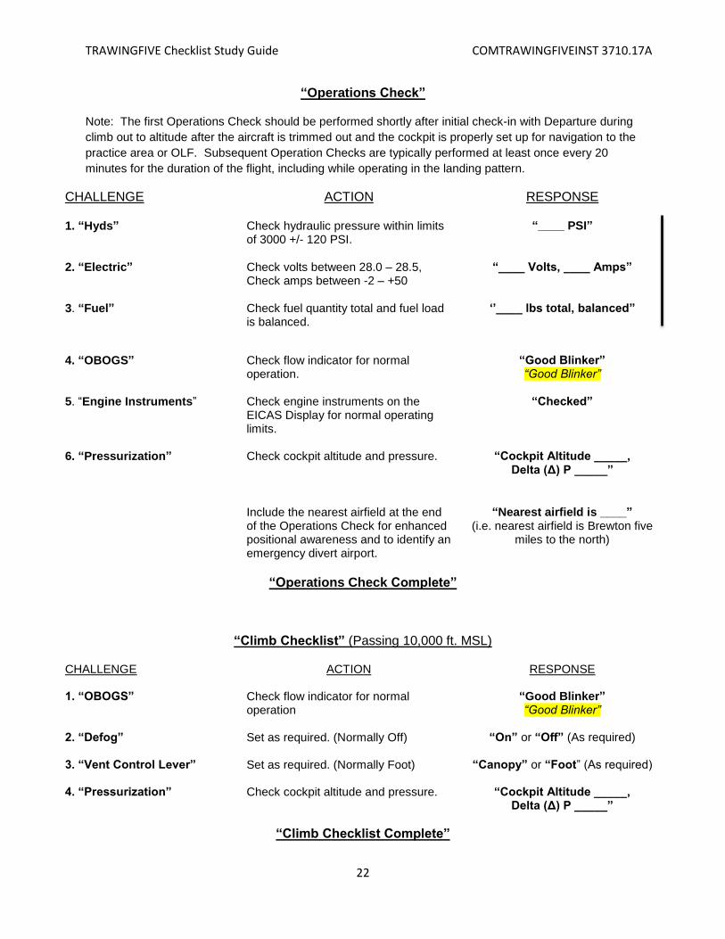
“Operations Check”
Note: The first Operations Check should be performed shortly after initial check-in with Departure during
climb out to altitude after the aircraft is trimmed out and the cockpit is properly set up for navigation to the
practice area or OLF. Subsequent Operation Checks are typically performed at least once every 20
minutes for the duration of the flight, including while operating in the landing pattern.
CHALLENGE ACTION RESPONSE 1. “Hyds” Check hydraulic pressure within limits
of 3000 +/- 120 PSI. “____ PSI”
2. “Electric” Check volts between 28.0 – 28.5,
Check amps between -2 – +50 “____ Volts, ____ Amps”
3. “Fuel” Check fuel quantity total and fuel load
is balanced. ‘’____ lbs total, balanced”
4. “OBOGS” Check flow indicator for normal
operation. “Good Blinker” “Good Blinker”
5. “Engine Instruments” Check engine instruments on the
EICAS Display for normal operating limits.
“Checked”
6. “Pressurization” Check cockpit altitude and pressure. “Cockpit Altitude _____,
Delta (Δ) P _____”
Include the nearest airfield at the end
of the Operations Check for enhanced positional awareness and to identify an emergency divert airport.
“Nearest airfield is ____” (i.e. nearest airfield is Brewton five
miles to the north)
“Operations Check Complete”
“Climb Checklist” (Passing 10,000 ft. MSL)
CHALLENGE ACTION RESPONSE 1. “OBOGS” Check flow indicator for normal
operation “Good Blinker” “Good Blinker”
2. “Defog” Set as required. (Normally Off) “On” or “Off” (As required) 3. “Vent Control Lever”
Set as required. (Normally Foot)
“Canopy” or “Foot” (As required)
4. “Pressurization” Check cockpit altitude and pressure. “Cockpit Altitude _____,
Delta (Δ) P _____”
“Climb Checklist Complete”
TRAWINGFIVE Checklist Study Guide COMTRAWINGFIVEINST 3710.17A
23
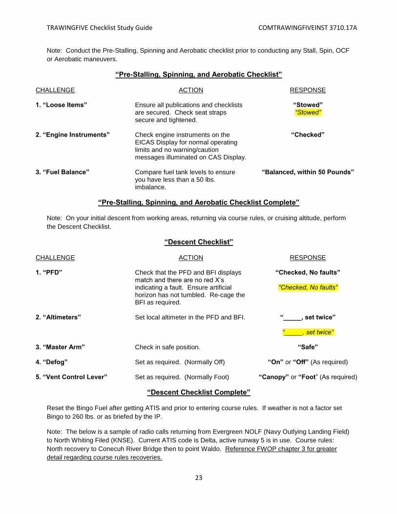
Note: Conduct the Pre-Stalling, Spinning and Aerobatic checklist prior to conducting any Stall, Spin, OCF
or Aerobatic maneuvers.
“Pre-Stalling, Spinning, and Aerobatic Checklist”
CHALLENGE ACTION RESPONSE 1. “Loose Items” Ensure all publications and checklists
are secured. Check seat straps secure and tightened.
“Stowed” “Stowed”
2. “Engine Instruments” Check engine instruments on the
EICAS Display for normal operating limits and no warning/caution messages illuminated on CAS Display.
“Checked”
3. “Fuel Balance” Compare fuel tank levels to ensure
you have less than a 50 lbs. imbalance.
“Balanced, within 50 Pounds”
“Pre-Stalling, Spinning, and Aerobatic Checklist Complete”
Note: On your initial descent from working areas, returning via course rules, or cruising altitude, perform
the Descent Checklist.
“Descent Checklist”
CHALLENGE ACTION RESPONSE 1. “PFD” Check that the PFD and BFI displays
match and there are no red X’s indicating a fault. Ensure artificial horizon has not tumbled. Re-cage the BFI as required.
“Checked, No faults”
“Checked, No faults”
2. “Altimeters” Set local altimeter in the PFD and BFI. “_____, set twice”
“_____, set twice”
3. “Master Arm” Check in safe position. “Safe” 4. “Defog” Set as required. (Normally Off) “On” or “Off” (As required) 5. “Vent Control Lever” Set as required. (Normally Foot) “Canopy” or “Foot” (As required)
“Descent Checklist Complete”
Reset the Bingo Fuel after getting ATIS and prior to entering course rules. If weather is not a factor set
Bingo to 260 lbs. or as briefed by the IP.
Note: The below is a sample of radio calls returning from Evergreen NOLF (Navy Outlying Landing Field)
to North Whiting Filed (KNSE). Current ATIS code is Delta, active runway 5 is in use. Course rules:
North recovery to Conecuh River Bridge then to point Waldo. Reference FWOP chapter 3 for greater
detail regarding course rules recoveries.

TRAWINGFIVE Checklist Study Guide COMTRAWINGFIVEINST 3710.17A
24
ACTION RESPONSE Prior to returning to KNSE via course
rules, switch to CH 12 (Pelican) on COM1 (UHF) and KNSE ATIS CH 1 on COM2 (VHF). Obtain ATIS while monitoring area common for traffic conflicts while approaching course rules.
“Switching Channel 12 on COM1 and ATIS on COM2”
(I.e. Pelican area common channel
12 will be up on UHF and KNSE ATIS will be up VHF channel 1).
Ensure you comply with the requirements for joining course rules (refer to the four A’s: ATIS, Altitude, Airspeed, Angle) IAW FWOP Chapter 3.
Over the east/west (southern) power line-slash switch to CH 6 on COM1 and check-in with Pensacola Approach. Pensacola Approach will provide a squawk. You are required to read back call.
“Switching Channel 6”
UHF: “Pensacola Approach, (call sign), Conecuh River Bridge, with
information (ATIS code)”
UHF: “(call sign), squawk_____”
Approaching Point Waldo, report it in
sight to Pensacola Approach. UHF: “(call sign), Waldo in sight”
When directed by Pensacola
Approach, but no later than Point Waldo switch to North Whiting Tower and check-in.
“Switching Channel 4”
UHF: “North Tower, (call sign), Waldo with (ATIS code)”
North Tower will respond:
Aircraft responds with:
“(Call sign), report the numbers, runway ___”
UHF: “(Call sign), WILCO”
Abeam the numbers, call North Tower
for clearance to break. UHF: “(call sign), numbers
runway ____” North Tower will respond:
Aircraft responds with:
“(Call sign), cleared to break”
UHF: “(call sign), roger break” Perform overhead break IAW FWOP
rules and CONTACT FTI procedures.
TRAWINGFIVE Checklist Study Guide COMTRAWINGFIVEINST 3710.17A
25
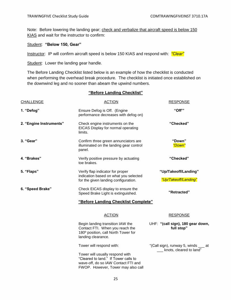
Note: Before lowering the landing gear; check and verbalize that aircraft speed is below 150
KIAS and wait for the instructor to confirm:
Student: “Below 150, Gear”
Instructor: IP will confirm aircraft speed is below 150 KIAS and respond with: “Clear”
Student: Lower the landing gear handle.
The Before Landing Checklist listed below is an example of how the checklist is conducted
when performing the overhead break procedure. The checklist is initiated once established on
the downwind leg and no sooner than abeam the upwind numbers.
“Before Landing Checklist”
CHALLENGE ACTION RESPONSE 1. “Defog” Ensure Defog is Off. (Engine
performance decreases with defog on) “Off’”
2. “Engine Instruments” Check engine instruments on the
EICAS Display for normal operating limits.
“Checked”
3. “Gear” Confirm three green annunciators are
illuminated on the landing gear control panel.
“Down” “Down”
4. “Brakes” Verify positive pressure by actuating
toe brakes. “Checked”
5. “Flaps” 6. “Speed Brake”
Verify flap indicator for proper indication based on what you selected for the given landing configuration. Check EICAS display to ensure the Speed Brake Light is extinguished.
“Up/Takeoff/Landing”
“Up/Takeoff/Landing”
“Retracted”
“Before Landing Checklist Complete”
ACTION
RESPONSE
Begin landing transition IAW the Contact FTI. When you reach the 180º position, call North Tower for landing clearance. Tower will respond with: Tower will usually respond with “Cleared to land.” If Tower calls to wave-off, do so IAW Contact FTI and FWOP. However, Tower may also call
UHF: “(call sign), 180 gear down,
full stop”
“(Call sign), runway 5, winds ___ at ___ knots, cleared to land”
TRAWINGFIVE Checklist Study Guide COMTRAWINGFIVEINST 3710.17A
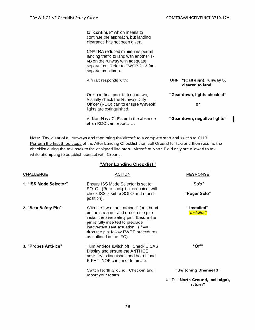
26
to “continue” which means to continue the approach, but landing clearance has not been given. CNATRA reduced minimums permit landing traffic to land with another T-6B on the runway with adequate separation. Refer to FWOP 2.13 for separation criteria. Aircraft responds with: On short final prior to touchdown, Visually check the Runway Duty Officer (RDO) cart to ensure Waveoff lights are extinguished. At Non-Navy OLF’s or in the absence of an RDO cart report……
UHF: “(Call sign), runway 5, cleared to land”
“Gear down, lights checked”
or
“Gear down, negative lights”
Note: Taxi clear of all runways and then bring the aircraft to a complete stop and switch to CH 3.
Perform the first three steps of the After Landing Checklist then call Ground for taxi and then resume the
checklist during the taxi back to the assigned line area. Aircraft at North Field only are allowed to taxi
while attempting to establish contact with Ground.
“After Landing Checklist”
CHALLENGE ACTION RESPONSE 1. “ISS Mode Selector” Ensure ISS Mode Selector is set to
SOLO. (Rear cockpit, if occupied, will check ISS is set to SOLO and report position).
“Solo”
“Roger Solo”
2. “Seat Safety Pin” With the “two-hand method” (one hand
on the streamer and one on the pin) install the seat safety pin. Ensure the pin is fully inserted to preclude inadvertent seat actuation. (If you drop the pin; follow FWOP procedures as outlined in the IFG).
“Installed” “Installed”
3. “Probes Anti-Ice” Turn Anti-Ice switch off. Check EICAS
Display and ensure the ANTI ICE advisory extinguishes and both L and R PHT INOP cautions illuminate.
“Off”
Switch North Ground. Check-in and
report your return. “Switching Channel 3”
UHF: “North Ground, (call sign),
return”
TRAWINGFIVE Checklist Study Guide COMTRAWINGFIVEINST 3710.17A
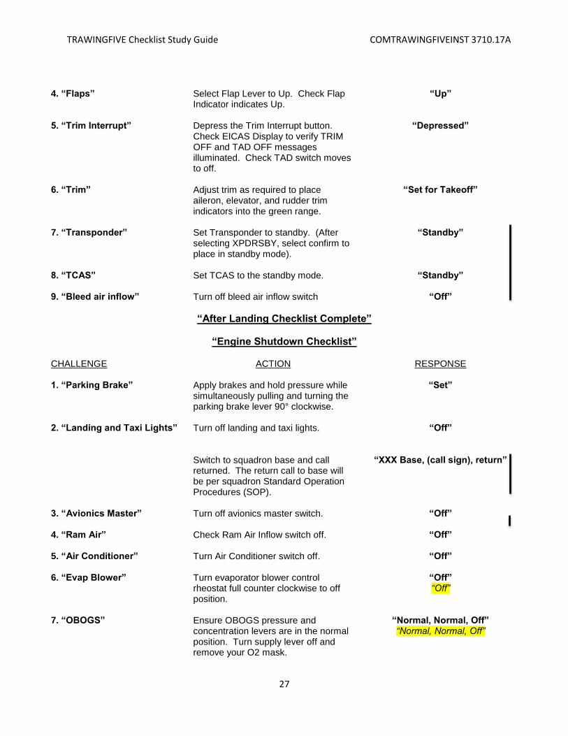
27
4. “Flaps” Select Flap Lever to Up. Check Flap
Indicator indicates Up. “Up”
5. “Trim Interrupt” Depress the Trim Interrupt button.
Check EICAS Display to verify TRIM OFF and TAD OFF messages illuminated. Check TAD switch moves to off.
“Depressed”
6. “Trim” Adjust trim as required to place
aileron, elevator, and rudder trim indicators into the green range.
“Set for Takeoff”
7. “Transponder” Set Transponder to standby. (After
selecting XPDRSBY, select confirm to place in standby mode).
“Standby”
8. “TCAS” Set TCAS to the standby mode. “Standby” 9. “Bleed air inflow” Turn off bleed air inflow switch “Off”
“After Landing Checklist Complete”
“Engine Shutdown Checklist”
CHALLENGE ACTION RESPONSE 1. “Parking Brake” Apply brakes and hold pressure while
simultaneously pulling and turning the parking brake lever 90° clockwise.
“Set”
2. “Landing and Taxi Lights” Turn off landing and taxi lights.
“Off”
Switch to squadron base and call returned. The return call to base will be per squadron Standard Operation Procedures (SOP).
“XXX Base, (call sign), return”
3. “Avionics Master” Turn off avionics master switch. “Off” 4. “Ram Air” Check Ram Air Inflow switch off. “Off” 5. “Air Conditioner” Turn Air Conditioner switch off. “Off” 6. “Evap Blower” Turn evaporator blower control
rheostat full counter clockwise to off position.
“Off” “Off”
7. “OBOGS” Ensure OBOGS pressure and concentration levers are in the normal position. Turn supply lever off and remove your O2 mask.
“Normal, Normal, Off” “Normal, Normal, Off”

TRAWINGFIVE Checklist Study Guide COMTRAWINGFIVEINST 3710.17A
28
8. “PCL” a. “Canopy”
Ensure PCL is in IDLE position for at least 60 seconds before setting PCL to off. Monitor engine instruments to verify proper shutdown (ITT and N1 decreasing, fuel flow at zero). While the prop is winding down, ensure the canopy rails are clear of obstructions and open canopy.
“Off”
“Rail Clear” “Rail Clear”
9. “Interior and Exterior Lights”
Turn off lights when propeller comes to a full stop.
“Off”
10. “PMU Status Message” Ensure PMU Status message is extinguished. (If a fault has been detected, the PMU Status message will illuminate 1 minute after touchdown; notify lineman).
“Extinguished”
11. “FDR Light” Check FDR light status. “Extinguished” 12. “Generator, Battery, and Aux Battery”
Turn Aux Battery, Generator and Battery switches off.
“Off”
13. “Gust Lock” Engage gust lock (as required). “Engaged”
“Engine Shutdown Checklist Complete”
The Before Leaving Aircraft Checklist will be conducted per the Pocket Checklist (PCL) or Quad-
Fold Checklist prior to leaving the aircraft after all flights. Due to time constraints, it will not be conducted
during simulator events.
Prior to leaving the aircraft and simulator, all aircrew will ensure leg restraints, upper and lower
Koch fittings, O2, and communication cords are properly stowed. Do not allow Koch fittings to slam
against CB panels or other equipment and keep them clear of the canopy piston. Ensure you take all
personal flight gear with you. Do not place anything other than flight gloves on the canopy transparency.
LEAVE NO PERSONAL ITEMS OR EQUIPMENT (FOD) IN THE COCKPITS!
Prior to stepping off the wing confirm visually that the Seat Safety Pin is installed, Canopy
Fracturing System (CFS) safety pin is installed, Power Control Lever (PCL) is off, starter switch/ ignition
switch are in the NORMAL position and the Interseat Sequencing System (ISS/Aft cockpit) is set to SOLO
position. Use the following verbiage after the checks are complete:
Front Cockpit: “Two Pins In, Off, Normal, Normal”
Rear Cockpit: “Two Pins In, Off, Normal, Normal, Solo”
Front Cockpit: “Roger, Solo”