Embed Size (px)
Citation preview
TRaX: A Multi-Threaded Architecture forReal-Time Ray Tracing
Josef Spjut Daniel Kopta Erik BrunvandSolomon Boulos School of Computing
University of UtahSalt Lake City, UT 84112
Spencer Kellis
ABSTRACTRay tracing is a technique used for generating highly realistic com-puter graphics images. In this paper, we explore the design of asimple but extremely parallel, multi-threaded, multi-core proces-sor architecture that performs real-time ray tracing. Our architec-ture, called TRaX for Threaded Ray eXecution, consists of a set ofthread states that include commonly used functional units for eachthread and share large functional units through a programmable in-terconnect to maximize utilization. The memory system takes ad-vantage of the application’s read-only access to the scene databaseand write-only access to the frame buffer output to provide efficientdata delivery with a relatively simple structure. Preliminary resultsindicate that a multi-core version of the architecture running at amodest speed of 500 MHz already provides real-time ray tracedimages for scenes of a complexity found in video games. We alsoexplore the architectural impact of a ray tracer that uses procedural(computed) textures rather than image-based (look-up) textures totrade computation for reduced memory bandwidth.
1. INTRODUCTIONAt present almost every personal computer has a dedicated pro-
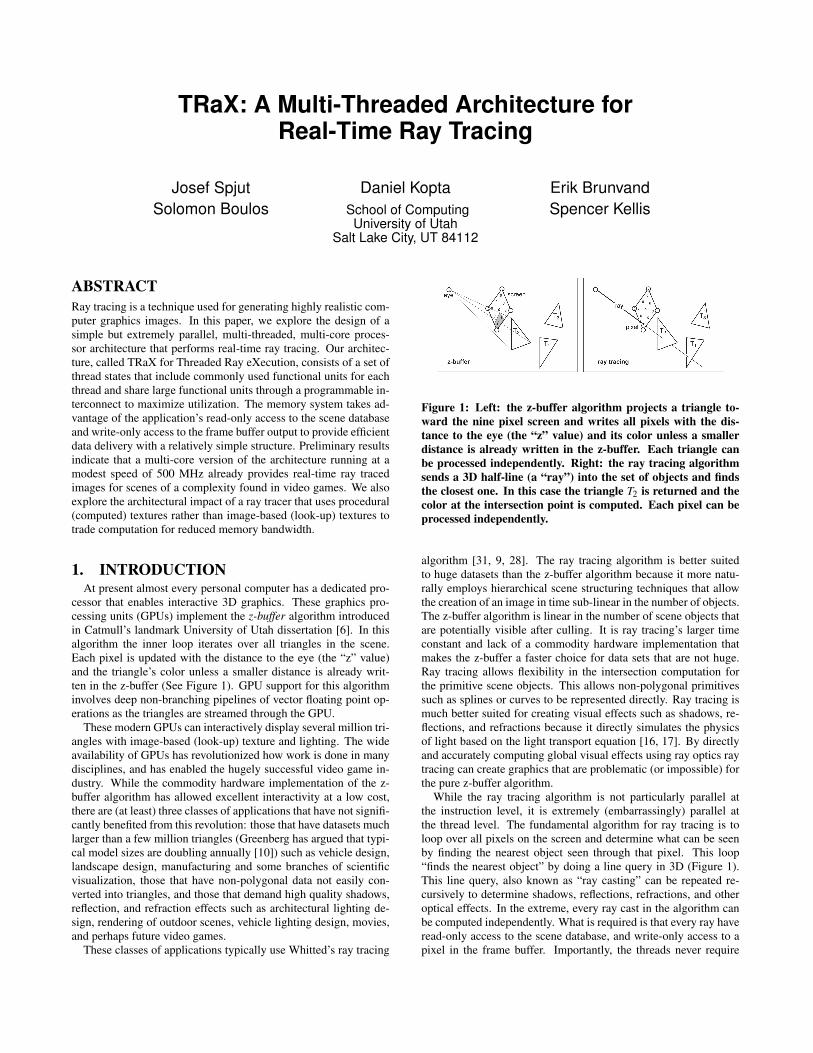
cessor that enables interactive 3D graphics. These graphics pro-cessing units (GPUs) implement the z-buffer algorithm introducedin Catmull’s landmark University of Utah dissertation [6]. In thisalgorithm the inner loop iterates over all triangles in the scene.Each pixel is updated with the distance to the eye (the “z” value)and the triangle’s color unless a smaller distance is already writ-ten in the z-buffer (See Figure 1). GPU support for this algorithminvolves deep non-branching pipelines of vector floating point op-erations as the triangles are streamed through the GPU.
These modern GPUs can interactively display several million tri-angles with image-based (look-up) texture and lighting. The wideavailability of GPUs has revolutionized how work is done in manydisciplines, and has enabled the hugely successful video game in-dustry. While the commodity hardware implementation of the z-buffer algorithm has allowed excellent interactivity at a low cost,there are (at least) three classes of applications that have not signifi-cantly benefited from this revolution: those that have datasets muchlarger than a few million triangles (Greenberg has argued that typi-cal model sizes are doubling annually [10]) such as vehicle design,landscape design, manufacturing and some branches of scientificvisualization, those that have non-polygonal data not easily con-verted into triangles, and those that demand high quality shadows,reflection, and refraction effects such as architectural lighting de-sign, rendering of outdoor scenes, vehicle lighting design, movies,and perhaps future video games.
These classes of applications typically use Whitted’s ray tracing
Figure 1: Left: the z-buffer algorithm projects a triangle to-ward the nine pixel screen and writes all pixels with the dis-tance to the eye (the “z” value) and its color unless a smallerdistance is already written in the z-buffer. Each triangle canbe processed independently. Right: the ray tracing algorithmsends a 3D half-line (a “ray”) into the set of objects and findsthe closest one. In this case the triangle T2 is returned and thecolor at the intersection point is computed. Each pixel can beprocessed independently.
algorithm [31, 9, 28]. The ray tracing algorithm is better suitedto huge datasets than the z-buffer algorithm because it more natu-rally employs hierarchical scene structuring techniques that allowthe creation of an image in time sub-linear in the number of objects.The z-buffer algorithm is linear in the number of scene objects thatare potentially visible after culling. It is ray tracing’s larger timeconstant and lack of a commodity hardware implementation thatmakes the z-buffer a faster choice for data sets that are not huge.Ray tracing allows flexibility in the intersection computation forthe primitive scene objects. This allows non-polygonal primitivessuch as splines or curves to be represented directly. Ray tracing ismuch better suited for creating visual effects such as shadows, re-flections, and refractions because it directly simulates the physicsof light based on the light transport equation [16, 17]. By directlyand accurately computing global visual effects using ray optics raytracing can create graphics that are problematic (or impossible) forthe pure z-buffer algorithm.
While the ray tracing algorithm is not particularly parallel atthe instruction level, it is extremely (embarrassingly) parallel atthe thread level. The fundamental algorithm for ray tracing is toloop over all pixels on the screen and determine what can be seenby finding the nearest object seen through that pixel. This loop“finds the nearest object” by doing a line query in 3D (Figure 1).This line query, also known as “ray casting” can be repeated re-cursively to determine shadows, reflections, refractions, and otheroptical effects. In the extreme, every ray cast in the algorithm canbe computed independently. What is required is that every ray haveread-only access to the scene database, and write-only access to apixel in the frame buffer. Importantly, the threads never require

communication with other threads.We propose a custom processor architecture for ray tracing called
TRaX (Threaded Ray eXecution). The TRaX processor exploitsthe thread rich nature of ray tracing by supporting multiple threadcontexts (thread processors) in each core. We use a form of dy-namic data-flow style instruction issue to discover parallelism be-tween threads, and share large less frequently used functional unitsbetween thread processors. We explore trade-offs between the num-ber of thread processors versus the number of functional units percore. The memory access style in ray tracing means that a rela-tively simple memory system can keep the multiple threads sup-plied with data. However, adding detailed image-based (look-up)textures to a scene can dramatically increase the required mem-ory bandwidth (as it does in a GPU). We also explore procedural(computed) textures as an alternative that trades computation formemory bandwidth. The resulting multiple-thread core can be re-peated on a multi-core chip because of the independent nature ofthe computation threads. Other thread-rich applications that couldtake advantage of the TRaX architecture include chess AI, imageand video processing, and cryptography.
2. BACKGROUND AND PREVIOUS WORKRay tracing can, of course, be implemented on general purpose
CPUs, and on specially programmed GPUs. Both approaches havebeen studied, along with a few previous studies of custom architec-tures.
2.1 Graphics Processing UnitsA carefully crafted computational pipeline for transforming tri-
angles and doing depth checks along with an equally carefully craftedmemory system to feed those pipelines makes our current gener-ation of z-buffer GPUs possible [1, 19]. Current GPUs have upto hundreds floating point units on a single GPU and aggregatememory bandwidth of 20-80 Gbytes per second from their on-chipmemories. That impressive on-chip memory bandwidth is largelyto support image-based (look-up) textures for the primitives. Thesecombine to achieve graphics performance that is orders of magni-tude higher than could be achieved by running the same algorithmson a general purpose processor.
The processing power of a GPU depends, to a large degree, onthe independence of each triangle being processed in the z-bufferalgorithm. This is what makes it possible to stream triangles throughthe GPU at rapid rates, and what makes it difficult to map ray trac-ing to a traditional GPU. There are three fundamental operationsthat must be supported for ray tracing: intersecting a ray with theacceleration structure that encapsulates the scene objects, intersect-ing the ray with the primitive objects contained in the element ofthe bounding structure that is hit, and computing the illuminationand color of the pixel based on the intersection with the primitiveobject and the collection of the contributions from the secondaryray segments. These operations require branching, pointer chasing,and decision making in each thread, and global access to the scenedatabase: operations that are relatively inefficient in a z-buffer-based architecture.
While it is possible to perform ray tracing on GPUs [24, 2, 11],these implementations have not been faster than the best CPU im-plementations, and they require the entire model to be in graphicscard memory. While some research continues on improving suchsystems, the traditional GPU architecture makes it unlikely that theapproach can be used on large geometric models. In particular theinefficiency of branching based on computations performed on theGPU, and the restricted memory model are serious issues for raytracing on a traditional GPU. The trend, however, in GPU archi-
tecture is towards more and more programmability of the graphicspipeline. Current high-end GPUs such as the G80 from nVidia,for example [21, 20], support both arbitrary memory accesses andbranching in the instruction set, and can thus, in theory, do bothpointer chasing and frequent branching. However, a G80 assumesthat every set of 32 threads (a “warp”) essentially executes the sameinstruction, and that they can thus be executed in SIMD manner.Branching is realized by (transparently) masking out threads. Thus,if branching often leads to diverging threads very low utilizationand performance will occur (similar arguments apply to pointerchasing). Results for parts of the ray tracing algorithm on a G80have been reported [11], but to date no complete ray tracing sys-tems have been reported on these new platforms.
2.2 General CPU ArchitecturesGeneral purpose architectures are also evolving to be perhaps
more compatible with ray tracing type applications. Almost allcommodity processors are now multi-core and include SIMD ex-tensions in the instruction set. By leveraging these extensions andstructuring the ray tracer to trace coherent packets of rays, researchershave demonstrated good frame rates even on single CPU cores [30,4]. The biggest difference in our approach is that we don’t dependon the coherence of the ray packet to extract thread-level paral-lelism. Thus our hardware should perform well even for secondaryrays used in advanced shading effects for which grouping the indi-vidual rays into coherent packets may not be easy.
The Sony Cell processor [15, 14] is an example of an architec-ture that might be quite interesting for ray tracing. With a 64-bitin-order power processor element (PPE) core (based on the IBMPower architecture) and eight synergistic processing elements (SPE),the Cell architecture sits somewhere between a general CPU and aGPU-style chip. Each SPE contains a 128x128 register file, 256kbof local memory (not a cache), and four floating point units op-erating in SIMD. When clocked at 3.2 GHz the Cell has a peakprocessing rate of 200GFlops. Researchers have shown that withcareful programming, and with using only shadow rays (no reflec-tions or refractions) for secondary rays, a ray tracer running on aCell can run 4 to 8 times faster than a single-core x86 CPU [3]. Inorder to get those speedups the ray tracer required careful mappinginto the scratch memories of the SPEs and managment of the SIMDbranching supported in the SPEs. We believe that our architecturecan improve on those performance numbers while not relying oncoherent packets of rays executing in a SIMD fashion.
2.3 Ray Tracing HardwareOther researchers have developed special-purpose hardware for
ray tracing [18, 12]. The most complete of these are the Saar-COR [25, 26] and Ray Processing Unit (RPU) [33, 32] architec-tures from Saarland University. SaarCOR is a custom hard-codedray trace processor, and RPU has a custom K-D tree traversal unitwith a programmable shader. Both are implemented and demon-strated on an FPGA. With an appropriately described scene (usingK-D trees and triangle data encoded with unit-triangle transforma-tions) the RPU can achieve very impressive frame rates, especiallywhen extrapolated to a potential CMOS ASIC implementation [32].
Our design is intended to be more flexible than the RPU byhaving all portions of the ray tracing algorithm be programmable,allowing the programmer to decide the appropriate accelerationstructure and primitive encoding, and by accelerating single rayperformance rather than using four-ray SIMD packets. There is,of course, a cost in terms of performance for this flexibility, but ifadequate frame rates can be achieved it will allow our architectureto be used in a wider variety of situations. There are many other
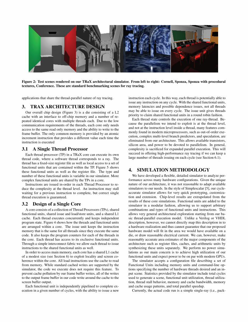
Figure 2: Test scenes rendered on our TRaX architectural simulator. From left to right: Cornell, Sponza, Sponza with proceduraltextures, Conference. These are standard benchmarking scenes for ray tracing.
applications that share the thread-parallel nature of ray tracing.
3. TRAX ARCHITECTURE DESIGNOur overall chip design (Figure 3) is a die consisting of a L2
cache with an interface to off-chip memory and a number of re-peated identical cores with multiple threads each. Due to the lowcommunication requirements of the threads, each core only needsaccess to the same read only memory and the ability to write to theframe buffer. The only common memory is provided by an atomicincrement instruction that provides a different value each time theinstruction is executed
3.1 A Single Thread ProcessorEach thread processor (TP) in a TRaX core can execute its own
thread code, where a software thread corresponds to a ray. Thethread has a fixed-size register file as well as local access to a set offunctional units that are contained within the TP. Figure 5 showsthese functional units as well as the register file. The type andnumber of these functional units is variable in our simulator. Morecomplex functional units are shared by the TPs in a core.
Instructions are issued in-order in each Thread Processor to re-duce the complexity at the thread level. An instruction may stallwaiting for a previous instruction to complete, but correct singlethread execution is guaranteed.
3.2 Design of a Single CoreA core consists of a collection of Thread Processors (TPs), shared
functional units, shared issue and load/store units, and a shared L1cache. Each thread executes concurrently and keeps independentprogram state. Figure 4 shows how the threads and functional unitsare arranged within a core. The issue unit keeps the instructionmemory that is the same for all threads since they execute the samecode. It also keeps the program counters for each of the threads inthe core. Each thread has access to its exclusive functional units.Through a simple interconnect fabric we allow each thread to issueinstructions to the shared functional units as well.
In order to access main memory, each core has a shared L1 cacheof a modest size (see Section 6) to exploit locality and screen co-herence within the core. All load instructions use the cache to readfrom memory. While standard cached writes are supported by thesimulator, the code we execute does not require this feature. Toprevent cache pollution by our frame buffer writes, all of the writesto the output frame buffer in our code write around the cache to thescreen buffer output.
Each functional unit is independently pipelined to complete ex-ecution in a given number of cycles, with the ability to issue a new
instruction each cycle. In this way, each thread is potentially able toissue any instruction on any cycle. With the shared functional units,memory latencies and possible dependence issues, not all threadsmay be able to issue on every cycle. The issue unit gives threadspriority to claim shared functional units in a round robin fashion.
Each thread state controls the execution of one ray-thread. Be-cause the parallelism we intend to exploit is at the thread level,and not at the instruction level inside a thread, many features com-monly found in modern microprocessors, such as out-of-order exe-cution, complex multi-level branch predictors, and speculation, areeliminated from our architecture. This allows available transistors,silicon area, and power to be devoted to parallelism. In general,complexity is sacrificed for expanded parallel execution. This willsucceed in offering high-performance ray tracing if we can keep alarge number of threads issuing on each cycle (see Section 6.1).
4. SIMULATION METHODOLOGYWe have developed a flexible, detailed simulator to analyze per-
formance across many hardware configurations. Given the uniquenature of our architecture, it was not reasonable to adapt availablesimulators to our needs. In the style of Simplescalar [5], our cycle-accurate simulator allows for very quick prototyping, customiza-tion and extension. Chip-level results are extrapolated from theresults of these core simulations. Functional units are added to thesimulator in a modular fashion, allowing us to support arbitrarycombinations and types of functional units and instructions. Thisallows very general architectural exploration starting from our ba-sic thread-parallel execution model. Unlike a Verilog or VHDLdescription, however, we cannot directly map this description in toa hardware realization and thus cannot guarantee that our proposedhardware model will fit in the area we would have available on adie, or draw reasonable electrical current. We can, however, makereasonably accurate area estimates of the major components of thearchitecture such as register files, caches, and arithmetic units bysynthesizing these units separately. We perform no power simu-lations as our main concern is to achieve high utilization of ourfunctional units and expect power to be on par with modern GPUs.
The simulator accepts a configuration file describing a set ofFunctional Units including memory units and command-line op-tions specifying the number of hardware threads desired and an in-put scene. Statistics provided by the simulator include total cyclesused to generate a scene, functional unit utilization, thread utiliza-tion, thread stall behavior, memory and cache bandwidth, memoryand cache usage patterns, and total parallel speedup.
Currently, the actual code run is a simple single-ray (i.e., pack-

Core0
Core1
Store,
Frame
Buff
L2
Coren
Chip
AtomicInc
Figure 3: Multi-Core Chip Lay-out
TP0
TP1
TP31
Flexible Interconnect
IMem / Issue
FP*
FP*
FP+/-
FP+/-
1 1 x
(4x)
(4x)
(2x)
(2cy)
(3cy)
(15cy)
(1cy)
L1(size variable,
see text)
Core (32-thread version)
(2x)Store,FrameBuff
L2
(4cy)(4cy)
Atomic
Load / Store / Atomic IncLoad / Store / Atomic Inc
1 1 x
Shared
Functional
Units
Inc
Figure 4: Core Block Diagram
3232
12
81
28 RF
Thread Processor
Cmp/Min/Max(1cy)
Add/Sub(2cy)
Logical(1cy)
Add/Sub(1cy)
Convert(1cy)
Branch(1cy)
Control
Int
FP
Figure 5: Thread Processor State
etless) ray caster that uses a bounding volume hierarchy (BVH) asits acceleration structure. We use the surface area heuristic to buildour hierarchy so that our simulated ray casting has memory behav-ior similar to that experienced by more full featured ray tracers.More details of this code are found in the next section.
Our ray tracing code is executed on simulated processors havingbetween 1 and 256 threads, with the number of all function unitsvarying between 1 and 64. The number of read and write ports tothe L1 cache was also varied. Images may be generated for anydesired screen size (see Figure 2 for examples of test scenes). Ourprimary goal for the current design phase is to determine the op-timal allocation of transistors to thread-level resources, includingfunctional units and thread state, in a single core to maximize uti-lization and overall parallel speedup. We are also looking carefullyat memory models and memory and cache usage to feed the parallelthreads (and parallel cores at the chip level).
For each simulation we render one frame in one core from scratchwith cold caches. The instructions are assumed to be already in theinstruction cache since they don’t change from frame to frame. Theresults we show are therefore an accurate representation of chang-ing the scene memory on every frame and requiring invalidatingthe caches. The results are conservative because even in a dynamicscene, much of the scene might stay the same from frame to frameand thus remain in the cache. We determine the time required torender a single frame and extrapolate the number of frames persecond from these results.
4.1 Functional UnitsFor a simple ray casting application, large, complex instruction
sets such as those seen in modern x86 processors are unnecessary.Our architecture implements a basic set of functional units with asimple but powerful ISA. We include bitwise instructions, branch-ing, floating point/integer conversion, memory operations, floatingpoint and integer add, subtract, multiply, reciprocal, and floatingpoint compare. We also include reciprocal square root because thatoperation occurs with some frequency in graphics code for normal-izing vectors.
We first chose a set of functional units to include in our machine-level language, shown in Table 1. This mix was chosen by sepa-rating different instruction “classes” into separate dedicated func-tional units. We implemented a ray casting benchmark using theseavailable resources, then ran numerous simulations varying the num-ber of threads and the width of each functional unit. All executionunits are assumed to be pipelined including the memory unit.
Each thread receives its own private FP Add/Sub execution unit.FP multiply is a crucial operation for ray-tracing. Cross and dot
Table 1: Default Functional Unit Mix (500MHz cycles)Latency
Unit Name Number of units (cycles)IntAddSub 1 / thread 1IntMul 1 / 8 threads 2FPAddSub 1 / thread 2FPMul 1 / 8 threads 3FPComp 1 / thread 1FPInvSqrt 1 / 16 threads 15Conversion 1 / thread 1Branch 1 / thread 1Cache 1 (mult. banks) varies
Table 2: Area Estimates (pre-layout) for functional unitsusing Artisan CMOS libraries and Synopsys. IBM8RFis a 130nm high performance cell library. IBM10LP isa 65nm low power cell library. Speed is similar for eachcircuit.
Area (µm2)Resource Name IBM8RF IBM10LP2kX16byte SRAM 1,761,578 503,000(est.)128X32 RF 77,533 22,00(est.)Integer Add/Sub 1,967 577Integer Multiply 30,710 12,690FP Add/Sub 14,385 2,596FP Multiply 27,194 8,980FP Compare 1,987 690FP InvSqrt 135,040 44,465Int to FP Conv 5,752 1,210
products, both of which require multiple FP multiplies, are com-mon in ray tracing applications. Other common operations suchas blending also use FP multiplies. The FP multiplier is a sharedunit because of its size, but due to its importance, it is only sharedamong a few threads. The FP Inv functional unit handles dividesand reciprocal square roots. The majority of these instructionscome from our box test algorithm, which issues three total FP Invinstructions. This unit is very large and less frequently used hence,it is shared among a greater number of threads.
5. RAY TRACING APPLICATIONThe ray tracing application used in all of our tests is written by
hand in assembly language to take advantage of the functional unitsand memory model supported in our architecture. The application
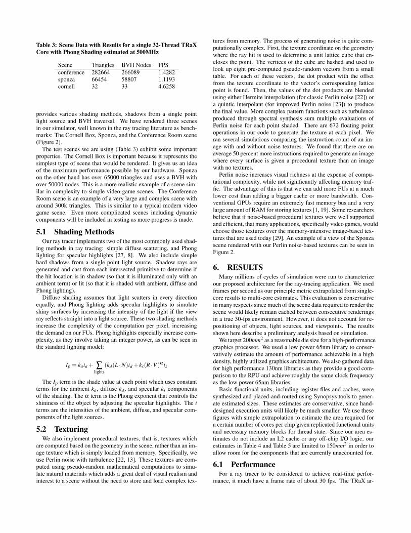
Table 3: Scene Data with Results for a single 32-Thread TRaXCore with Phong Shading estimated at 500MHz
Scene Triangles BVH Nodes FPSconference 282664 266089 1.4282sponza 66454 58807 1.1193cornell 32 33 4.6258
provides various shading methods, shadows from a single pointlight source and BVH traversal. We have rendered three scenesin our simulator, well known in the ray tracing literature as bench-marks: The Cornell Box, Sponza, and the Conference Room scene(Figure 2).
The test scenes we are using (Table 3) exhibit some importantproperties. The Cornell Box is important because it represents thesimplest type of scene that would be rendered. It gives us an ideaof the maximum performance possible by our hardware. Sponzaon the other hand has over 65000 triangles and uses a BVH withover 50000 nodes. This is a more realistic example of a scene sim-ilar in complexity to simple video game scenes. The ConferenceRoom scene is an example of a very large and complex scene witharound 300k triangles. This is similar to a typical modern videogame scene. Even more complicated scenes including dynamiccomponents will be included in testing as more progress is made.
5.1 Shading MethodsOur ray tracer implements two of the most commonly used shad-
ing methods in ray tracing: simple diffuse scattering, and Phonglighting for specular highlights [27, 8]. We also include simplehard shadows from a single point light source. Shadow rays aregenerated and cast from each intersected primitive to determine ifthe hit location is in shadow (so that it is illuminated only with anambient term) or lit (so that it is shaded with ambient, diffuse andPhong lighting).
Diffuse shading assumes that light scatters in every directionequally, and Phong lighting adds specular highlights to simulateshiny surfaces by increasing the intensity of the light if the viewray reflects straight into a light source. These two shading methodsincrease the complexity of the computation per pixel, increasingthe demand on our FUs. Phong highlights especially increase com-plexity, as they involve taking an integer power, as can be seen inthe standard lighting model:
Ip = kaia + ∑lights
(kd(L ·N)id + ks(R ·V )α is
The Ip term is the shade value at each point which uses constantterms for the ambient ka, diffuse kd , and specular ks componentsof the shading. The α term is the Phong exponent that controls theshininess of the object by adjusting the specular highlights. The iterms are the intensities of the ambient, diffuse, and specular com-ponents of the light sources.
5.2 TexturingWe also implement procedural textures, that is, textures which
are computed based on the geometry in the scene, rather than an im-age texture which is simply loaded from memory. Specifically, weuse Perlin noise with turbulence [22, 13]. These textures are com-puted using pseudo-random mathematical computations to simu-late natural materials which adds a great deal of visual realism andinterest to a scene without the need to store and load complex tex-
tures from memory. The process of generating noise is quite com-putationally complex. First, the texture coordinate on the geometrywhere the ray hit is used to determine a unit lattice cube that en-closes the point. The vertices of the cube are hashed and used tolook up eight pre-computed pseudo-random vectors from a smalltable. For each of these vectors, the dot product with the offsetfrom the texture coordinate to the vector’s corresponding latticepoint is found. Then, the values of the dot products are blendedusing either Hermite interpolation (for classic Perlin noise [22]) ora quintic interpolant (for improved Perlin noise [23]) to producethe final value. More complex pattern functions such as turbulenceproduced through spectral synthesis sum multiple evaluations ofPerlin noise for each point shaded. There are 672 floating pointoperations in our code to generate the texture at each pixel. Weran several simulations comparing the instruction count of an im-age with and without noise textures. We found that there are onaverage 50 percent more instructions required to generate an imagewhere every surface is given a procedural texture than an imagewith no textures.
Perlin noise increases visual richness at the expense of compu-tational complexity, while not significantly affecting memory traf-fic. The advantage of this is that we can add more FUs at a muchlower cost than adding a bigger cache or more bandwidth. Con-ventional GPUs require an extremely fast memory bus and a verylarge amount of RAM for storing textures [1, 19]. Some researchersbelieve that if noise-based procedural textures were well supportedand efficient, that many applications, specifically video games, wouldchoose those textures over the memory-intensive image-based tex-tures that are used today [29]. An example of a view of the Sponzascene rendered with our Perlin noise-based textures can be seen inFigure 2.
6. RESULTSMany millions of cycles of simulation were run to characterize
our proposed architecture for the ray-tracing application. We usedframes per second as our principle metric extrapolated from single-core results to multi-core estimates. This evaluation is conservativein many respects since much of the scene data required to render thescene would likely remain cached between consecutive renderingsin a true 30-fps environment. However, it does not account for re-positioning of objects, light sources, and viewpoints. The resultsshown here describe a preliminary analysis based on simulation.
We target 200mm2 as a reasonable die size for a high-performancegraphics processor. We used a low power 65nm library to conser-vatively estimate the amount of performance achievable in a highdensity, highly utilized graphics architecture. We also gathered datafor high performance 130nm libraries as they provide a good com-parison to the RPU and achieve roughly the same clock frequencyas the low power 65nm libraries.
Basic functional units, including register files and caches, weresynthesized and placed-and-routed using Synopsys tools to gener-ate estimated sizes. These estimates are conservative, since hand-designed execution units will likely be much smaller. We use thesefigures with simple extrapolation to estimate the area required fora certain number of cores per chip given replicated functional unitsand necessary memory blocks for thread state. Since our area es-timates do not include an L2 cache or any off-chip I/O logic, ourestimates in Table 4 and Table 5 are limited to 150mm2 in order toallow room for the components that are currently unaccounted for.
6.1 PerformanceFor a ray tracer to be considered to achieve real-time perfor-
mance, it much have a frame rate of about 30 fps. The TRaX ar-
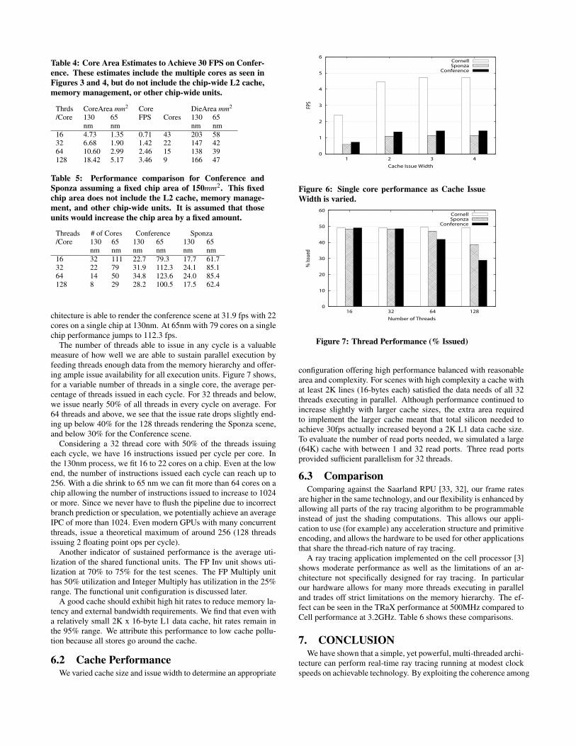
Table 4: Core Area Estimates to Achieve 30 FPS on Confer-ence. These estimates include the multiple cores as seen inFigures 3 and 4, but do not include the chip-wide L2 cache,memory management, or other chip-wide units.
Thrds CoreArea mm2 Core DieArea mm2
/Core 130 65 FPS Cores 130 65nm nm nm nm
16 4.73 1.35 0.71 43 203 5832 6.68 1.90 1.42 22 147 4264 10.60 2.99 2.46 15 138 39128 18.42 5.17 3.46 9 166 47
Table 5: Performance comparison for Conference andSponza assuming a fixed chip area of 150mm2. This fixedchip area does not include the L2 cache, memory manage-ment, and other chip-wide units. It is assumed that thoseunits would increase the chip area by a fixed amount.
Threads # of Cores Conference Sponza/Core 130 65 130 65 130 65
nm nm nm nm nm nm16 32 111 22.7 79.3 17.7 61.732 22 79 31.9 112.3 24.1 85.164 14 50 34.8 123.6 24.0 85.4128 8 29 28.2 100.5 17.5 62.4
chitecture is able to render the conference scene at 31.9 fps with 22cores on a single chip at 130nm. At 65nm with 79 cores on a singlechip performance jumps to 112.3 fps.
The number of threads able to issue in any cycle is a valuablemeasure of how well we are able to sustain parallel execution byfeeding threads enough data from the memory hierarchy and offer-ing ample issue availability for all execution units. Figure 7 shows,for a variable number of threads in a single core, the average per-centage of threads issued in each cycle. For 32 threads and below,we issue nearly 50% of all threads in every cycle on average. For64 threads and above, we see that the issue rate drops slightly end-ing up below 40% for the 128 threads rendering the Sponza scene,and below 30% for the Conference scene.
Considering a 32 thread core with 50% of the threads issuingeach cycle, we have 16 instructions issued per cycle per core. Inthe 130nm process, we fit 16 to 22 cores on a chip. Even at the lowend, the number of instructions issued each cycle can reach up to256. With a die shrink to 65 nm we can fit more than 64 cores on achip allowing the number of instructions issued to increase to 1024or more. Since we never have to flush the pipeline due to incorrectbranch prediction or speculation, we potentially achieve an averageIPC of more than 1024. Even modern GPUs with many concurrentthreads, issue a theoretical maximum of around 256 (128 threadsissuing 2 floating point ops per cycle).
Another indicator of sustained performance is the average uti-lization of the shared functional units. The FP Inv unit shows uti-lization at 70% to 75% for the test scenes. The FP Multiply unithas 50% utilization and Integer Multiply has utilization in the 25%range. The functional unit configuration is discussed later.
A good cache should exhibit high hit rates to reduce memory la-tency and external bandwidth requirements. We find that even witha relatively small 2K x 16-byte L1 data cache, hit rates remain inthe 95% range. We attribute this performance to low cache pollu-tion because all stores go around the cache.
6.2 Cache PerformanceWe varied cache size and issue width to determine an appropriate
0
1
2
3
4
5
6
1 2 3 4
FPS
Cache Issue Width
CornellSponza
Conference
Figure 6: Single core performance as Cache IssueWidth is varied.
0
10
20
30
40
50
60
16 32 64 128%
Issu
ed
Number of Threads
CornellSponza
Conference
Figure 7: Thread Performance (% Issued)
configuration offering high performance balanced with reasonablearea and complexity. For scenes with high complexity a cache withat least 2K lines (16-bytes each) satisfied the data needs of all 32threads executing in parallel. Although performance continued toincrease slightly with larger cache sizes, the extra area requiredto implement the larger cache meant that total silicon needed toachieve 30fps actually increased beyond a 2K L1 data cache size.To evaluate the number of read ports needed, we simulated a large(64K) cache with between 1 and 32 read ports. Three read portsprovided sufficient parallelism for 32 threads.
6.3 ComparisonComparing against the Saarland RPU [33, 32], our frame rates
are higher in the same technology, and our flexibility is enhanced byallowing all parts of the ray tracing algorithm to be programmableinstead of just the shading computations. This allows our appli-cation to use (for example) any acceleration structure and primitiveencoding, and allows the hardware to be used for other applicationsthat share the thread-rich nature of ray tracing.
A ray tracing application implemented on the cell processor [3]shows moderate performance as well as the limitations of an ar-chitecture not specifically designed for ray tracing. In particularour hardware allows for many more threads executing in paralleland trades off strict limitations on the memory hierarchy. The ef-fect can be seen in the TRaX performance at 500MHz compared toCell performance at 3.2GHz. Table 6 shows these comparisons.
7. CONCLUSIONWe have shown that a simple, yet powerful, multi-threaded archi-
tecture can perform real-time ray tracing running at modest clockspeeds on achievable technology. By exploiting the coherence among
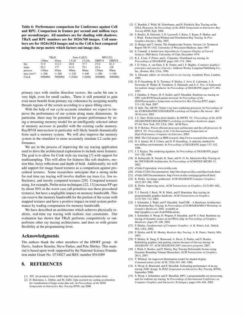
Table 6: Performance comparison for Conference against Celland RPU. Comparison in frames per second and million raysper second(mrps). All numbers are for shading with shadows.TRaX and RPU numbers are for 1024x768 images. Cell num-bers are for 1024x1024 images and so the Cell is best comparedusing the mrps metric which factors out image size.
TRaX Sony Cell[3] RPU[32]130nm 65nm 1 Cell 2 Cells DRPU4 DRPU8
fps 31.9 112.3 20.0 37.7 27.0 81.2mrps 50.2 177 41.9 79.1 42.4 128process 130nm 65nm 90nm 90nm 130nm 90nmarea (mm2) ≈ 200 ≈ 200 ≈ 220 ≈ 440 ≈ 200 ≈ 190Clock 500MHz 500MHz 3.2GHz 3.2GHz 266MHz 400MHz
primary rays with similar direction vectors, the cache hit rate isvery high, even for small caches. There is still potential to gaineven more benefit from primary ray coherence by assigning nearbythreads regions of the screen according to a space filling curve.
With the help of our cycle-accurate simulator we expect to im-prove the performance of our system along many dimensions. Inparticular, there may be potential for greater performance by us-ing a streaming memory model for an intelligently selected subsetof memory accesses in parallel with the existing cache memory.Ray/BVH intersection in particular will likely benefit dramaticallyfrom such a memory system. We will also improve the memorysystem in the simulator to more accurately simulate L2 cache per-formance.
We are in the process of improving the ray tracing applicationused to drive the architectural exploration to include more features.The goal is to allow for Cook style ray tracing [7] with support formultisampling. This will allow for features like soft shadows, mo-tion blur, fuzzy reflections and depth of field. Additionally, we willadd support for image based textures as a comparison against pro-cedural textures. Some researchers anticipate that a strong nichefor real time ray tracing will involve shallow ray trees (i.e. few re-flections), and mostly computed textures [29]. Computed texturesusing, for example, Perlin noise techniques [22, 13] increase FP opsby about 50% in the worst case (all primitives use these proceduraltextures), but have a negligible impact on memory bandwidth. Thiscan reserve the memory bandwidth for the portion of the scene withmapped textures and have a positive impact on total system perfor-mance by trading computation for memory bandwidth.
We have described an architecture which achieves physically re-alistic, real-time ray tracing with realistic size constraints. Ourevaluation has shown that TRaX performs competitively or out-performs other ray tracing architectures, and does so with greaterflexibility at the programming level.
AcknowledgmentsThe authors thank the other members of the HWRT group: AlDavis, Andrew Kensler, Steve Parker, and Pete Shirley. This mate-rial is based upon work supported by the National Science Founda-tion under Grant No. 0734027 and REU number 0541009
8. REFERENCES
[1] ATI. Ati products from AMD. http://ati.amd.com/products/index.html.[2] D. Balciunas, L. Dulley, and M. Zuffo. Gpu-assisted ray casting acceleration
for visualization of large scene data sets. In Proceedings of the IEEESymposium on Interactive Ray Tracing RT06, sep 2006.
[3] C. Benthin, I. Wald, M. Scherbaum, and H. Friedrich. Ray Tracing on theCELL Processor. In Proceedings of the IEEE Symposium on Interactive RayTracing RT06, Sept. 2006.
[4] S. Boulos, D. Edwards, J. D. Lacewell, J. Kniss, J. Kautz, P. Shirley, andI. Wald. Packet-based Whitted and Distribution Ray Tracing. In Proc.Graphics Interface, May 2007.
[5] D. Burger and T. Austin. The Simplescalar Toolset, Version 2.0. TechnicalReport TR-97-1342, University of Wisconsin-Madison, June 1997.
[6] E. Catmull. A Subdivision Algorithm for Computer Display of CurvedSurfaces. PhD thesis, University of Utah, December 1974.
[7] R. L. Cook, T. Porter, and L. Carpenter. Distributed ray tracing. InProceedings of SIGGRAPH, pages 165–174, 1984.
[8] J. D. Foley, A. van Dam, S. K. Feiner, and J. F. Hughes. Computer graphics:principles and practice (2nd ed.). Addison-Wesley Longman Publishing Co.,Inc., Boston, MA, USA, 1990.
[9] A. Glassner, editor. An introduction to ray tracing. Academic Press, London,1989.
[10] D. P. Greenberg, K. E. Torrance, P. Shirley, J. Arvo, E. Lafortune, J. A.Ferwerda, B. Walter, B. Trumbore, S. Pattanaik, and S.-C. Foo. A frameworkfor realistic image synthesis. In Proceedings of SIGGRAPH, pages 477–494,1997.
[11] J. Gunther, S. Popov, H.-P. Seidel, and P. Slusallek. Realtime ray tracing onGPU with BVH-based packet traversal. In Proceedings of theIEEE/Eurographics Symposium on Interactive Ray Tracing RT07, pages113–118, Sept. 2007.
[12] D. Hall. The AR350: Today’s ray trace rendering processor. In Proceedings ofthe EUROGRAPHICS/SIGGRAPH workshop on Graphics Ha rdware - Hot3D Session, 2001.
[13] J. C. Hart. Perlin noise pixel shaders. In HWWS ’01: Proceedings of the ACMSIGGRAPH/EUROGRAPHICS workshop on Graphics hardware, pages87–94, New York, NY, USA, 2001. ACM Press.
[14] H. P. Hofstee. Power efficient processor architecture and the cell processor. InHPCA ’05: Proceedings of the 11th International Symposium onHigh-Performance Computer Architecture, 2005.
[15] IBM. The Cell project at IBM research. http://www.research.ibm.com/cell.[16] D. S. Immel, M. F. Cohen, and D. P. Greenberg. A radiosity method for
non-diffuse environments. In Proceedings of SIGGRAPH, pages 133–142,1986.
[17] J. T. Kajiya. The rendering equation. In Proceedings of SIGGRAPH, pages143–150, 1986.
[18] H. Kobayashi, K. Suzuki, K. Sano, and N. O. ba. Interactive Ray-Tracing onthe 3DCGiRAM Architecture. In Proceedings of ACM/IEEE MICRO-35,2002.
[19] nVidia Corporation. www.nvidia.com.[20] nVidia CUDA Documentation. http://developer.nvidia.com/object/cuda.html.[21] nVidia G80 Documentation. http://www.nvidia.com/page/geforce8.html.[22] K. Perlin. An image synthesizer. ACM SIGGRAPH Computer Graphics,
19(3):287–296, 1985.[23] K. Perlin. Improving noise. ACM Transactions on Graphics, 21(3):681–682,
2002.[24] T. J. Purcell, I. Buck, W. R. Mark, and P. Hanrahan. Ray tracing on
programmable graphics hardware. ACM Transactions on Graphics,21(3):703–712, 2002.
[25] J. Schmittler, I. Wald, and P. Slusallek. SaarCOR – A Hardware Architecturefor Realtime Ray-Tracing. In Proceedings of EUROGRAPHICS Workshop onGraphics Hardware, 2002. available athttp://graphics.cs.uni-sb.de/Publications.
[26] J. Schmittler, S. Woop, D. Wagner, P. Slusallek, and W. J. Paul. Realtime raytracing of dynamic scenes on an FPGA chip. In Proceedings of GraphicsHardware, pages 95–106, 2004.
[27] P. Shirley. Fundamentals of Computer Graphics. A. K. Peters, Ltd., Natick,MA, USA, 2002.
[28] P. Shirley and R. K. Morley. Realistic Ray Tracing. A. K. Peters, Natick, MA,2003.
[29] P. Shirley, K. Sung, E. Brunvand, A. Davis, S. Parker, and S. Boulos.Rethinking graphics and gaming courses because of fast ray tracing. InSIGGRAPH ’07: ACM SIGGRAPH 2007 educators program, 2007.
[30] I. Wald, S. Boulos, and P. Shirley. Ray Tracing Deformable Scenes usingDynamic Bounding Volume Hierarchies. ACM Transactions on Graphics,26(1), 2007.
[31] T. Whitted. An improved illumination model for shaded display.Communications of the ACM, 23(6):343–349, 1980.
[32] S. Woop, E. Brunvand, and P. Slusallak. Estimating performance of an raytracing ASIC design. In IEEE Symposium on Interactive Ray Tracing (RT06),September 2006.
[33] S. Woop, J. Schmittler, and P. Slusallek. RPU: a programmable ray processingunit for realtime ray tracing. In Proceedings of International Conference onComputer Graphics and Interactive Techniques, pages 434–444, 2005.