Embed Size (px)
Citation preview
"'
ALBERTAPublic Works, Supply and Services
Property Management Division
Water Treatment Coordinators' Meeting
Supply & Services Building, Edmonton
1 May 1985
TREATMENT OF OPEN RECIRCULATING COOLING WATER SYSTEMS
By
G.F.Yuzwa, P.Eng
H20 ENGINEERING LTD.
539 Edgemont Bay NW
Calgary, AlbertaT3A 2K7
PAGE 1
INTRODUCTION
At the Water Treatment Coordinators' meeting in April of 1981, the
paper entitled "Treatment of Cooling Waters" was presented by thewriter. This paper gave a general overview of such topics as typesof cooling water systems, scale formation, forms of corrosion,
prediction of scaling/corrosion, measurement of corrosion rates,
organic growths, external treatment for scale and corrosion control,chemical treatment for scale control, chemical treatment for corrosion
control, and microbiological control.
Although some of these topics are also delt with herein, it is theintent of this paper to provide the reader with specific set points
for field operation based on a minimal amount of theoretical
discussion on the treatment of open recirculating cooling water
systems within buildings managed by ALBERTA Public Works.
Therefore, such topics as system description, scale and corrosion
control, biological control, and monitoring of scale and corrosion are
presented herein.
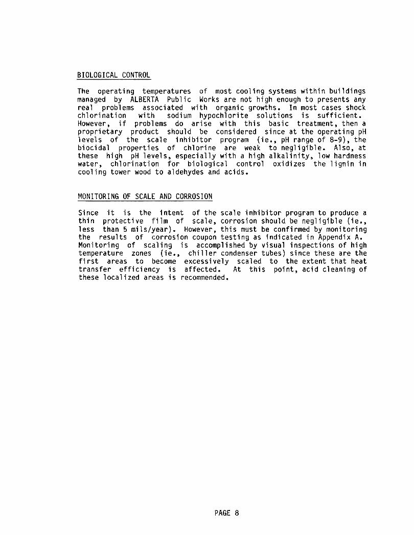
SYSTEM DESCRIPTION
The basic components of an open recirculating cooling water system
consist of a wet cooling tower, a heat exchanger, a circulating pump,
a manual bleed-off valve, and metered make-up water with a float
valve. However, additional components such as an automatic bleed-off
system, louver screens, a by-pass filter, a chemical feeder, an acid
injection system, and a softener may also be present. The physical
arrangement of these components are indicated in Figure 1 of Appendix
A.
Cooling towers remove heat by evaporative cooling of a stream of waterthat continuously passes through a heat exchanger. However, during
this process, only pure water is evaporated, thus resulting in a
concentration build-up of the constituents in the circulating water.
There is also a build-up of air-borne constituents (ie., poplar fluff,
dust, carbon dioxide, sulfur dioxide, etc.) in the circulating waterdue to the scrubbing action of the water as it contacts the air. It
is because of this build-up of constituents that the circulating water
of open recirculating cooling systems must be treated for scale,
corrosion, and bacteriological control.
PAGE 2
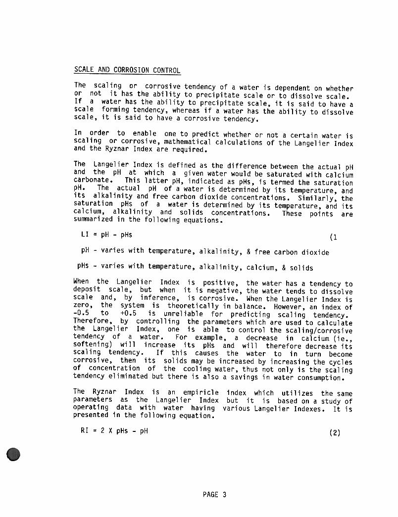
SCALE AND CORROSION CONTROL
The scaling or corrosive tendency of a water is dependent on whether
or not it has the ability to precipitate scale or to dissolve scale.
If a water has the ability to precipitate scale, it is said to have a
scale forming tendency, whereas if a water has the ability to dissolve
scale, it is said to have a corrosive tendency.
In order to enable one to predict whether or not a certain water is
scaling or corrosive, mathematical calculations of the Langelier Indexand the Ryznar Index are required.
The Langelier Index is defined as the difference between the actual pH
and the pH at which a given water would be saturated with calcium
carbonate. This latter pH, indicated as pHs, is termed the saturation
pH. The actual pH of a water is determined by its temperature, andits alkalinity and free carbon dioxide concentrations. Similarly, the
saturation pHs of a water is determined by its temperature, and its
calcium, alkalinity and solids concentrations. These points aresummarized in the following equations.
LI = pH -pHs(1
pH -varies with temperature, alkalinity, & free carbon dioxide
pHs -varies with temperature, alkalinity, calcium, & solids
When the Langelier Index is positive, the water has a tendency to
deposit scale, but when it is negative, the water tends to dissolvescale and, by inference, is corrosive. When the Langelier Index is
zero, the system is theoretically in balance. However, an index of
-0.5 to +0.5 is unreliable for predicting scaling tendency.
Therefore, by controlling the parameters which are used to calculatethe Langelier Index, one is able to control the scaling/corrosive
tendency of a water. For example, a decrease in calcium (ie.,
softening) will increase its pHs and will therefore decrease its
scaling tendency. If this causes the water to in turn becomecorrosive, then its solids may be increased by increasing the cyclesof concentration of the cooling water, thus not only is the scaling
tendency eliminated but there is also a savings in water consumption.
The Ryznar Index is an empiricle
parameters as the Langelier Index
operating data with water having
presented in the following equation.
index which utilizes the same
but it is based on a study of
various Langelier Indexes. It is
RI = 2 X pHs -pH(2)
PAGE 3
SCALE AND CORROSION CONTROL(continued)
For this index, the value of 6.5 is the neutral point. Values of 6 or
less indicate scaling and values of 7 or more indicate a corrosive
tendency.
The control points for the Langelier and Ryznar Indexes are determined
by the type of water treatment program which is used and the quality
of the make-up water.
When a corrosion inhibitor such as chromate is used, the water is
intentionally controlled at a negative Langelier Index and a Ryznar
Index greater than 7, whereas when a scale inhibitor such as hexameta
phosphate is used, the water is intentionally controlled at a positive
Langelier Index and a Ryznar Index less than 6 in order to take
advantage of the corrosion protection offered by a thin film of
calcium salts.
Since the disposal of chromates into sanitary sewer systems has been
reduced to a level of 5 ppm maximum for most municipalities, this
treatment program is no longer recommended for use in buildings
managed by ALBERTA Public Works.
A scale inhibitor program utilizes either proprietary or
non-proprietary chemicals. However, softening of the make-up water isrequired when non-proprietary chemicals are utilized. If the cooling
system is operational only during a portion of the year, it is moreeconomical to utilize proprietary chemicals, eventhough they are far
more expensive than the non-proprietary chemicals. However, if the
cooling system is operational year round, it is more economical topurchase a softener and use non-proprietary chemicals.
Since the control set points vary somewhat for each proprietary
chemical, they should be obtained from the supplier of the particularchemical being used. Therefore, only the control set points for the
non-proprietary chemical program are developed herein.
The non-proprietary chemical program utilizes sodium hexameta
phosphate feeding in conjunction with softening of the make-up water.Sodium hexameta phosphate is added to the basin of the cooling tower
such that a poly phosphate residual concentration of 10-20 ppm P04 is
maintained in the cooling system. Softening of the make-up is
required because the phosphate can not handle the full hardness load.
PAGE 4
SCALE AND CORROSION CONTROL(continued)
However, since 20-50 ppm of hardness are required to react with thehexameta phosphate in order to lay down the protective harness film,
hardness leakage from the softener must be encouraged. If there is
insufficient natural hardness leakage from the softener, it may be
increased by increasing the flow rate through the softener or
partially by-passing the softener.
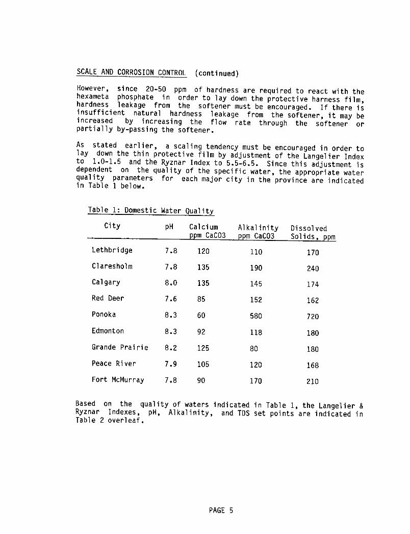
As stated earlier, a scaling tendency must be encouraged in order to
lay down the thin protective film by adjustment of the Langelier Indexto 1.0-1.5 and the Ryznar Index to 5.5-6.5. Since this adjustment is
dependent on the quality of the specific water, the appropriate water
quality parameters for each major city in the province are indicatedin Table 1 below.
Table 1: Domestic Water Quality'J
City pH Calcium Alkalinity Dissolved
ppm CaCO3 ppm CaCO3 Solids, ppm
Lethbridge 7.8 120 110 170
Claresholm 7.8 135 190 240
Calgary 8.0 135 145 174
Red Deer 7.6 85 152 162
Ponoka 8.3 60 580 720
Edmonton 8.3 92 118 180
Grande Prairie 8.2 125 80 180
Peace River 7.9 105 120 168
Fort McMurray 7.8 90 170 210
Based on the quality of waters indicated in Table I, the Langelier &
Ryznar Indexes, pH, Alkalinity, and TDS set points are indicated inTable 2 overleaf.
PAGE 5
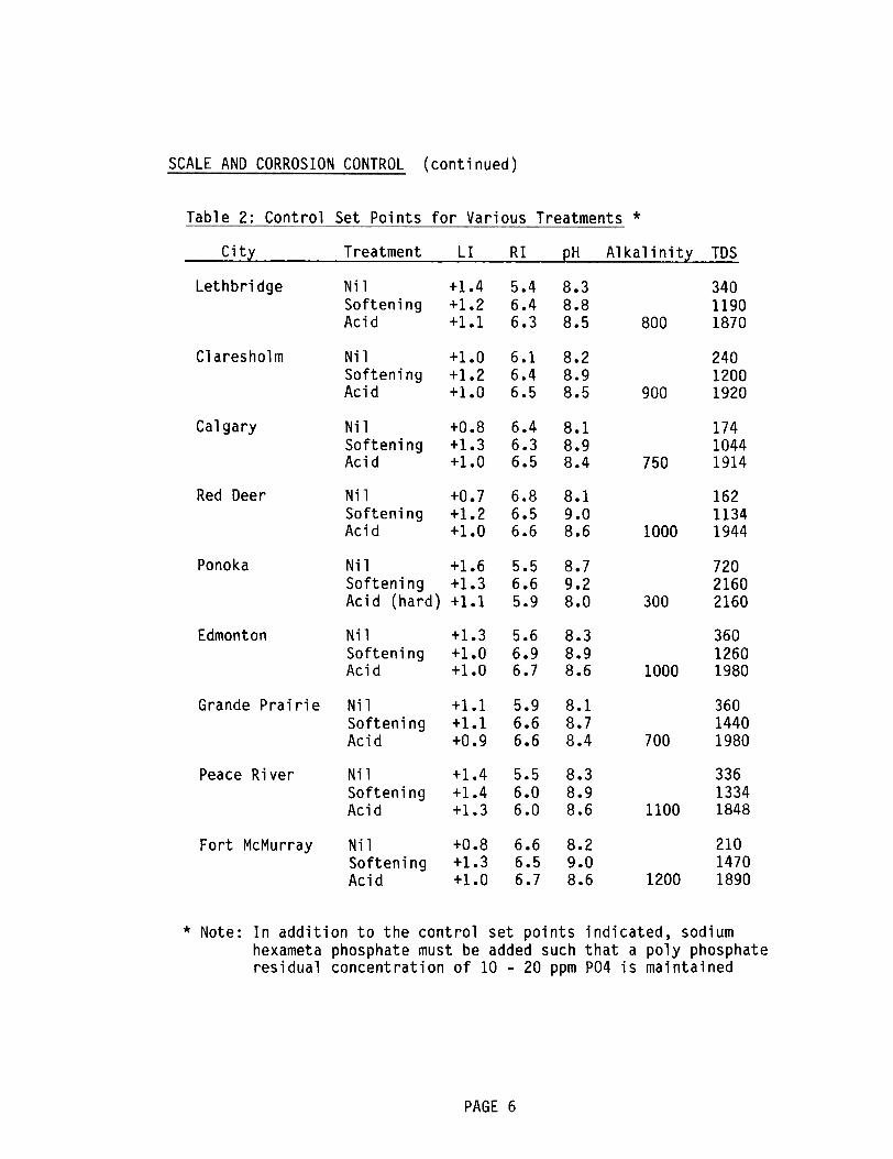
SCALE AND CORROSION CONTROL (continued)
Table 2: Control Set Points for Various Treatments *
City Treatment LI RI pH Alkalinity TDS
Lethbridge +1.4+1.2+1.1
5.46.46.3
8.38.88.5
34011901870
Nil
SofteningAcid 800
Claresholm +1.0+1.2+1.0
6.16.46.5
8.28.98.5
24012001920
Nil
SofteningAcid 900
Calgary +0.8+1.3+1.0
6.46.36.5
8.18.98.4
17410441914
Nil
SofteningAcid 750
Red Deer +0.7+1.2+1.0
6.86.56.6
8.19.08.6
16211341944
Nil
SofteningAcid 1000
Ponoka Nil +1.6
Softening +1.3
Acid (hard) +1.1
8.79.28.0
5.56.65.9
72021602160300
Edmonton +1.3+1.0+1.0
5.66.96.7
8.38.98.6
36012601980
Nil
SofteningAcid 1000
Grande Prairie +1.1+1.1+0.9
36014401980
5.96.66.6
8.18.78.4
Nil
SofteningAcid 700
8.38.98.6
33613341848
Peace River +1.4+1.4+1.3
5.56.06.0 1100
21014701890
Fort McMurray +0.8+1.3+1.0
6.66.56.7
8.29.08.6
Nil
SofteningAcid 1200
* Note: In addition to the control set points indicated, sodium
hexameta phosphate must be added such that a poly phosphate
residual concentration of 10- 20 ppm P04 is maintained
PAGE 6
Nil
SofteningAcid
SCALE AND CORROSION CONTROL(continued)
The "Nil" treatment indicated in Table 2 refers to the use of domestic
water in the cooling system, whereas the "Softening" treatment refers
softening the make-up and "Acid" refers to softening the make-up
(except for Ponoka) and metering acid to the basin of the coolingtower.
With regard to the "Nil" treatment, the quality of water in these
cities dictates that only one cycle, and in some cases only two
cycles, of concentration may be tolerated, otherwise there would be
massive precipitation of hardness in the system.
When water is softened, it becomes corrosive. Therefore, in order to
counteract this effect, the TDS of the system is allowed to increaseto such a point that the water will have a slightly scaling tendency.
This also reduces water consumption.
When acid is added to softened water, its alkalinity is reduced and it
becomes even more corrosive than only softening. Therefore, the TDS
is increased in order to counteract this effect. Thus, the water
consumption is reduced even more than straight softening. However, an
upper limit of 2000 ppm TDS is recommended in order to minimize
galvanic corrosion.
Acid treatment
the system is
hardness.
of
very
unsoftened make-up water is not recommended unless
large and the make-up water is low in calcium
Since the high temperature and alkalinity will in time convert the
poly phosphate to ortho phosphate (ie., hexameta phosphate convertedto trisodium phosphate), precipitation of the hardness will occur and
the suspended solids in the system will increase. Should the
suspended solids increase beyond 100 ppm due to this reason or due tothe accumulation of crud from the atmosphere, the system should be
drained and flushed and consideration should be given to a by-pass
filter installation.
It must be emphasized here that the control set points indicated in
Table 2 are based on the quality of domestic water indicated in Table
1. Should the quality of domestic water differ from that indicated,
these set points must be revised accordingly.
PAGE 7
BIOLOGICAL CONTROL
The operating temperatures of most cooling systems within buildings
managed by ALBERTA Public Works are not high enough to presents any
real problems associated with organic growths. In most cases shockchlorination with sodium hypochlorite solutions is sufficient.
However, if problems do arise with this basic treatment, then a
proprietary product should be considered since at the operating pH
levels of the scale inhibitor program (ie., pH range of 8-9), the
biocidal properties of chlorine are weak to negligible. Also, at
these high pH levels, especially with a high alkalinity, low hardness
water, chlorination for biological control oxidizes the lignin in
cooling tower wood to aldehydes and acids.
MONITORING OF SCALE AND CORROSION
Since it is the intent of the scale inhibitor program to produce a
thin protective film of scale, corrosion should be negligible (ie.,
less than 5 mils/year). However, this must be confirmed by monitoringthe results of corrosion coupon testing as indicated in Appendix A.
Monitoring of scaling is accomplished by visual inspections of high
temperature zones (ie., chiller condenser tubes) since these are the
first areas to become excessively scaled to the extent that heat
transfer efficiency is affected. At this point, acid cleaning of
these localized areas is recommended.
PAGE 8

APPENDIX A
~igure 1~-SchematicQi!!!!Jram ~! Typical Open Recirculating Colling Wat~r Systef1!
Moisture Loss
Cooling Water Return
,I
.,
",...,
"' I ,
"-.. Ii'-.. (1~II
/..
Heat
Exchanger
1, /
II--""' Air Inlet
I ThroughIi'..."'. S c reens
I' ,./
Treatment
Chemicals0£:=
Cooling
Water
i,t/ Supply
A
...Blowdown
(~ '-*-'
Circulating
PumpMetered Make-up
Through Softener By-passFilter
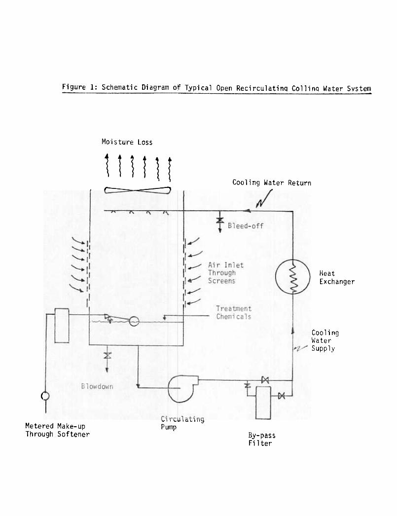
INSTRUCTIONS FOR CORROSION TEST COUPONS
The results from corrosion test coupons are valuable only when thecoupons are used properly. Tests must be made at locations where
water temperature and flow velocity past the coupon are similar to
conditions in important plant piping and equipment.
Exceptarea,
for situations where you are interested in a specific trouble
AVOID
-high velocity locations (ie., immediately downstream of
centrifugal pump discharge)-low velocity locations (ie., storage tanks, cooling tower
sumps, condensate receivers
DO
-keep the metal coupon in a dry place before installation
-select a location where the coupon will be continuously
submerged-install mounting plugs with directional mounting groove
parallel to flow
-use steel screws with steel coupons, brass screws with
copper coupons-use insulating gasket between screws and coupon
-leave coupons installed for at least 30 days
DO NOT
-cut or trim coupon to fit it into a pipe line
-jam coupon against inside of pipe
-handle coupon more than is necessary
-use excessive amounts of pipe dope which may coat coupon
-locate coupon where oils may accumulate
It is often desirable to use coupons in several locations at the same
time. One reason for this is that test results from several similar
test locations permit the calculation of an average corrosion rate. A
second reason is to make possible a comparison of corrosion rates in
different areas.
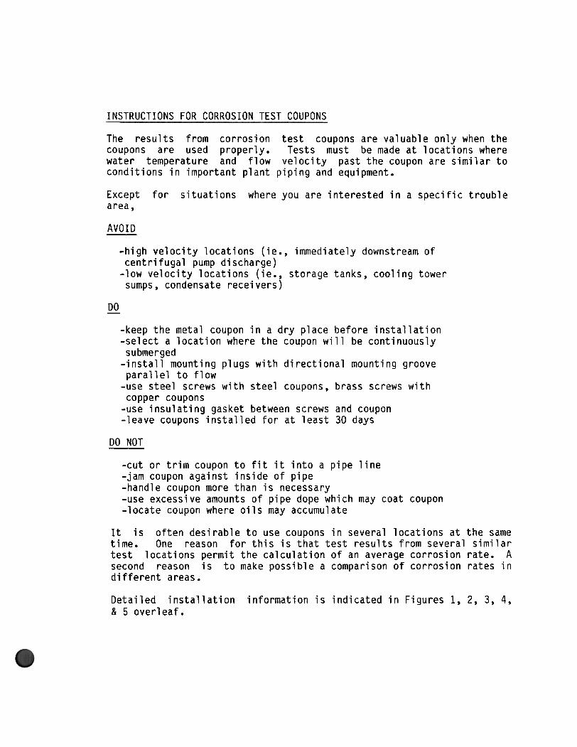
Detailed installation
& 5 overleaf.
information is indicated in Figures 1, 2, 3,4,
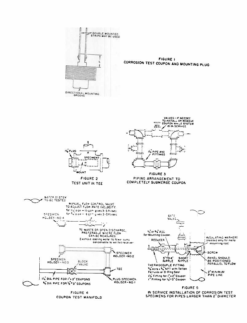
FIGURE ICORROSION TEST COUPON AND MOUNTING PLUG
A
VALVES -iF NEEDEDTO INSTALL OR AEMOI/£
c-.=;--" COUPON WH;~r SYSTEM
~~~ / IS IN SE"R\lICE
~ --r , L,. "- 71- ,r--- , ;1 ~ , " , I' U -- ; I' I
---i ~ ~i I
4-:.~ ~::c-:;1;i c.:i-.JIJ' II "-~ Pf "IF- .:r i :, .I! 1;.-.,..-" -I~. PIPE" AND I! -;,-$l'
q: ~ / FITTINGS ~-tI i' !
()::J'$=J/:)
FIGURE 3
PIPING ARRANGEMENT TO
COMPLETELY SUBMERGE COUPON
I"I;.PLUG , A r
~ U -L..fli:- SPECIMENT
I D" -0---F ~ I
'f i I J ." : II . -I,,:-: .-r: J~-~I i
i.JMo'UNT ~
FIGURE 2
TEST UNIT IN TEE
u..r F' cvc--.,
"- , -~ , t ..
---cy i(; c£ iESi(~M/)~Jl.~ F"LO\' CO"TR:J;.. Vl.L\