Embed Size (px)
Citation preview

TRF79x0ATB NFC/HF RFID Reader Module
User's Guide
Literature Number: SLOU372AJune 2013–Revised June 2014
Contents
1 TRF79x0ATB Module Descriptions ......................................................................................... 52 TRF79x0ATB Connections and Technical Details..................................................................... 63 TRF79x0ATB Module Schematic ............................................................................................ 84 MSP-EXP430F5529 Experimenters Board .............................................................................. 115 LM4F232 Evaluation Kit (EK-LM4F232).................................................................................. 126 DK-LM3S9B96-EM2-TRF7960R ARM Cortex M-3 Development Board........................................ 137 Quick Start ........................................................................................................................ 148 Base Application Firmware .................................................................................................. 149 Mechanical and Physical Information.................................................................................... 1510 Antenna Tuning Details ....................................................................................................... 1511 TRF79x0ATB Module Read Ranges ...................................................................................... 1912 References ........................................................................................................................ 20Revision History.......................................................................................................................... 21
2 Table of Contents SLOU372A–June 2013–Revised June 2014Submit Documentation Feedback
Copyright © 2013–2014, Texas Instruments Incorporated
www.ti.com
List of Figures1 TRF7960ATB Evaluation Module.......................................................................................... 52 TRF7970ATB Evaluation Module.......................................................................................... 63 TRF79x0ATB Module Schematic .......................................................................................... 84 MSP-EXP430F5438 Development Board ................................................................................ 95 Debug Header (RF3) Logic Analyzer Connections for Monitoring SPI Communications Between
MSP430F5438A and TRF79x0A on TRF79x0ATB Module .......................................................... 106 Firmware Development and Debug Setup for MSP-EXP430F5438 Experimenters Board....................... 107 MSP-EXP430F5529 Development Board............................................................................... 118 MSP-EXP430F5539 RF EVM Header Pinouts (RF1 and RF2) ...................................................... 119 Debug Header (J12) Logic Analyzer Connections for Monitoring SPI Communications Between
MSP430F5529 and TRF79x0A on TRF79x0ATB Module ............................................................ 1210 EK-LM4F232 Development Platform (EM header locations on backside).......................................... 1211 DK-LM3S9B96-EM2-TRF7960R Development Platform.............................................................. 1312 Theoretical Parallel Resistor Value for Desired Q ..................................................................... 1713 Theoretical Capacitance Values for Resonance at Desired Q ....................................................... 17
List of Tables1 Connector P1/RF1 ........................................................................................................... 62 Connector P2/RF2 ........................................................................................................... 7
3SLOU372A–June 2013–Revised June 2014 List of FiguresSubmit Documentation Feedback
Copyright © 2013–2014, Texas Instruments Incorporated
User's GuideSLOU372A–June 2013–Revised June 2014
TRF79x0ATB NFC/HF RFID Reader Module
This evaluation module provides directions for TRF7960A and TRF7970A users to implement a 13.56-MHz NFC/RFID reader solution using the TRF79x0A IC connected to a Texas Instruments embeddedmicrocontroller or microprocessor development platform. Examples of such development platforms are:the MSP-EXP430F5438 board, MSP-EXP430F5529 board, the ARM® Cortex™-M3/M4-based board, orany other TI embedded microcontroller platforms with the EM socket headers populated.
This document also covers the TRF79x0ATB module as it relates to using the module for evaluation anddevelopment purposes in conjunction with Texas Instruments Embedded Development platforms. It doesnot cover the in-depth details of the TRF79x0A NFC/RFID IC families, as those details are welldocumented in the data sheets for those parts, along with application reports that can be found on theproduct pages (see Section 12).
FCC/IC Regulatory Compliance:• FCC – FEDERAL COMMUNICATIONS COMMISSION Part 15, Class A Compliant• IC – INDUSTRY CANADA Class A Compliant
Tiva is a trademark of Texas Instruments.4 TRF79x0ATB NFC/HF RFID Reader Module SLOU372A–June 2013–Revised June 2014Stellaris, StellarisWare are registered trademarks of Texas Instruments.
Submit Documentation FeedbackCortex is a trademark of ARM Limited.Copyright © 2013–2014, Texas Instruments IncorporatedARM is a registered trademark of ARM Limited.
All other trademarks are the property of their respective owners.
www.ti.com TRF79x0ATB Module Descriptions
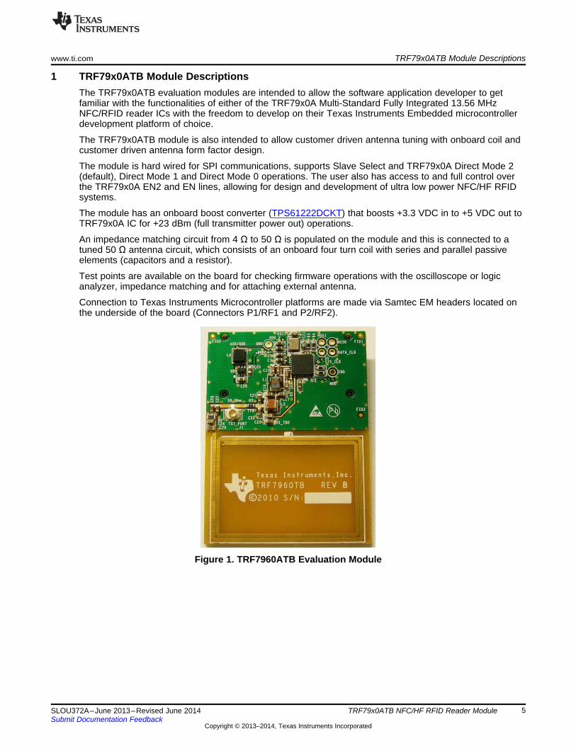
1 TRF79x0ATB Module DescriptionsThe TRF79x0ATB evaluation modules are intended to allow the software application developer to getfamiliar with the functionalities of either of the TRF79x0A Multi-Standard Fully Integrated 13.56 MHzNFC/RFID reader ICs with the freedom to develop on their Texas Instruments Embedded microcontrollerdevelopment platform of choice.
The TRF79x0ATB module is also intended to allow customer driven antenna tuning with onboard coil andcustomer driven antenna form factor design.
The module is hard wired for SPI communications, supports Slave Select and TRF79x0A Direct Mode 2(default), Direct Mode 1 and Direct Mode 0 operations. The user also has access to and full control overthe TRF79x0A EN2 and EN lines, allowing for design and development of ultra low power NFC/HF RFIDsystems.
The module has an onboard boost converter (TPS61222DCKT) that boosts +3.3 VDC in to +5 VDC out toTRF79x0A IC for +23 dBm (full transmitter power out) operations.
An impedance matching circuit from 4 Ω to 50 Ω is populated on the module and this is connected to atuned 50 Ω antenna circuit, which consists of an onboard four turn coil with series and parallel passiveelements (capacitors and a resistor).
Test points are available on the board for checking firmware operations with the oscilloscope or logicanalyzer, impedance matching and for attaching external antenna.
Connection to Texas Instruments Microcontroller platforms are made via Samtec EM headers located onthe underside of the board (Connectors P1/RF1 and P2/RF2).
Figure 1. TRF7960ATB Evaluation Module
5SLOU372A–June 2013–Revised June 2014 TRF79x0ATB NFC/HF RFID Reader ModuleSubmit Documentation Feedback
Copyright © 2013–2014, Texas Instruments Incorporated
TRF79x0ATB Connections and Technical Details www.ti.com
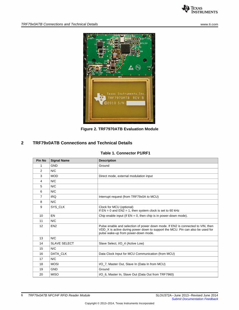
Figure 2. TRF7970ATB Evaluation Module
2 TRF79x0ATB Connections and Technical Details
Table 1. Connector P1/RF1
Pin No Signal Name Description1 GND Ground2 N/C3 MOD Direct mode, external modulation input4 N/C5 N/C6 N/C7 IRQ Interrupt request (from TRF79x0A to MCU)8 N/C9 SYS_CLK Clock for MCU (optional)
If EN = 0 and EN2 = 1, then system clock is set to 60 kHz10 EN Chip enable input (If EN = 0, then chip is in power-down mode).11 N/C12 EN2 Pulse enable and selection of power down mode. If EN2 is connected to VIN, then
VDD_X is active during power down to support the MCU. Pin can also be used forpulse wake-up from power-down mode.
13 N/C14 SLAVE SELECT Slave Select, I/O_4 (Active Low)15 N/C16 DATA_CLK Data Clock Input for MCU Communication (from MCU)17 N/C18 MOSI I/O_7, Master Out, Slave In (Data In from MCU)19 GND Ground20 MISO I/O_6, Master In, Slave Out (Data Out from TRF7960)
6 TRF79x0ATB NFC/HF RFID Reader Module SLOU372A–June 2013–Revised June 2014Submit Documentation Feedback
Copyright © 2013–2014, Texas Instruments Incorporated
www.ti.com TRF79x0ATB Connections and Technical Details
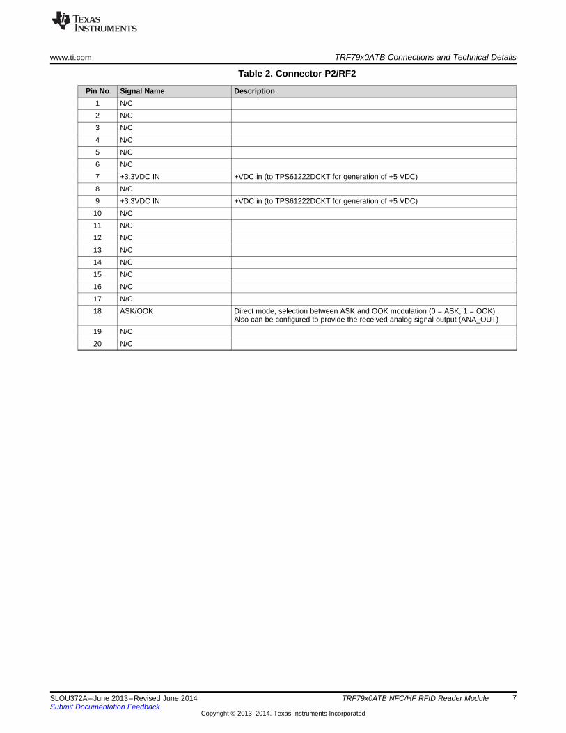
Table 2. Connector P2/RF2
Pin No Signal Name Description1 N/C2 N/C3 N/C4 N/C5 N/C6 N/C7 +3.3VDC IN +VDC in (to TPS61222DCKT for generation of +5 VDC)8 N/C9 +3.3VDC IN +VDC in (to TPS61222DCKT for generation of +5 VDC)
10 N/C11 N/C12 N/C13 N/C14 N/C15 N/C16 N/C17 N/C18 ASK/OOK Direct mode, selection between ASK and OOK modulation (0 = ASK, 1 = OOK)
Also can be configured to provide the received analog signal output (ANA_OUT)19 N/C20 N/C
7SLOU372A–June 2013–Revised June 2014 TRF79x0ATB NFC/HF RFID Reader ModuleSubmit Documentation Feedback
Copyright © 2013–2014, Texas Instruments Incorporated
TRF79x0ATB Module Schematic www.ti.com
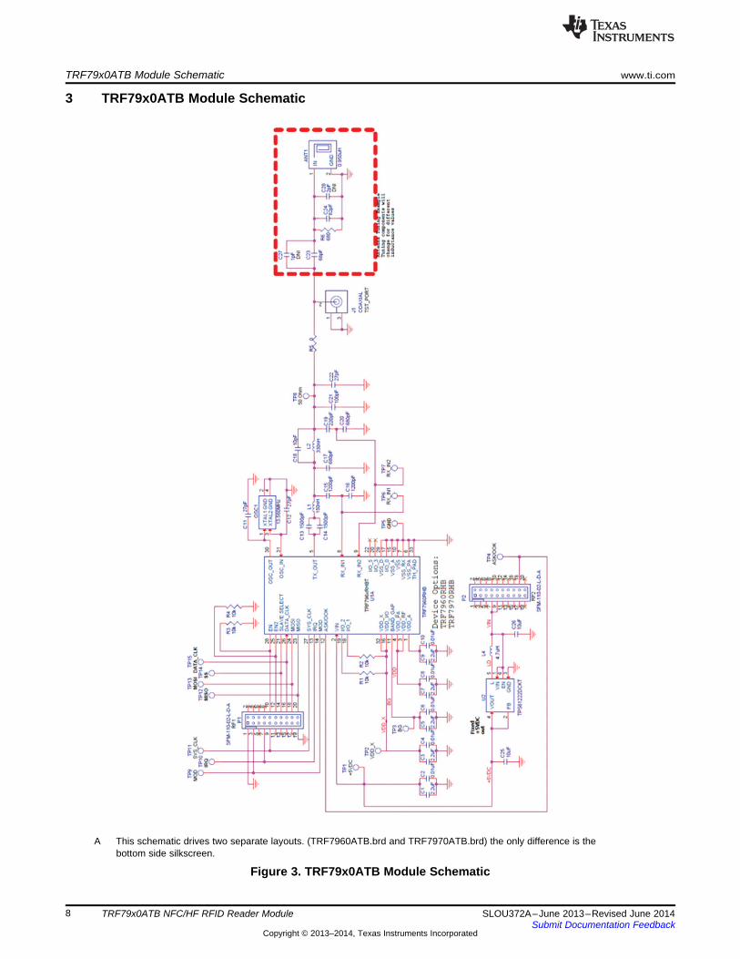
3 TRF79x0ATB Module Schematic
A This schematic drives two separate layouts. (TRF7960ATB.brd and TRF7970ATB.brd) the only difference is thebottom side silkscreen.
Figure 3. TRF79x0ATB Module Schematic
8 TRF79x0ATB NFC/HF RFID Reader Module SLOU372A–June 2013–Revised June 2014Submit Documentation Feedback
Copyright © 2013–2014, Texas Instruments Incorporated
TRF79x0ATBmodule
connects here
Rf3 DebugHeader
www.ti.com TRF79x0ATB Module Schematic
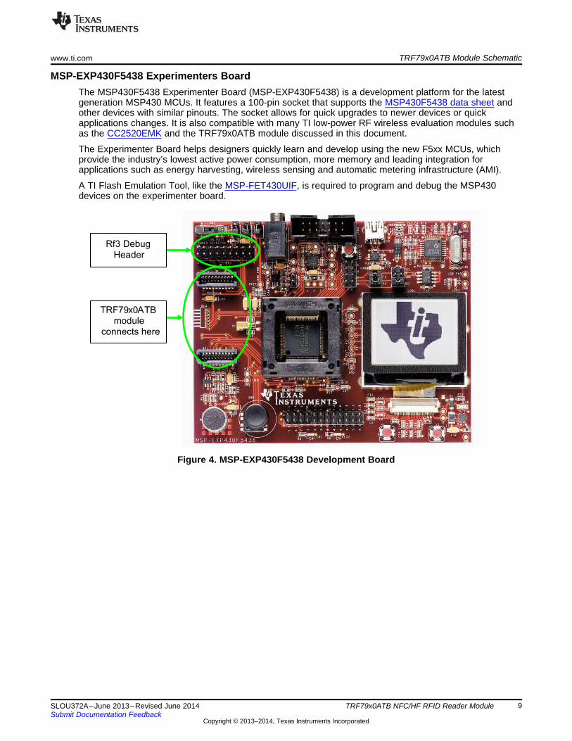
MSP-EXP430F5438 Experimenters BoardThe MSP430F5438 Experimenter Board (MSP-EXP430F5438) is a development platform for the latestgeneration MSP430 MCUs. It features a 100-pin socket that supports the MSP430F5438 data sheet andother devices with similar pinouts. The socket allows for quick upgrades to newer devices or quickapplications changes. It is also compatible with many TI low-power RF wireless evaluation modules suchas the CC2520EMK and the TRF79x0ATB module discussed in this document.
The Experimenter Board helps designers quickly learn and develop using the new F5xx MCUs, whichprovide the industry’s lowest active power consumption, more memory and leading integration forapplications such as energy harvesting, wireless sensing and automatic metering infrastructure (AMI).
A TI Flash Emulation Tool, like the MSP-FET430UIF, is required to program and debug the MSP430devices on the experimenter board.
Figure 4. MSP-EXP430F5438 Development Board
9SLOU372A–June 2013–Revised June 2014 TRF79x0ATB NFC/HF RFID Reader ModuleSubmit Documentation Feedback
Copyright © 2013–2014, Texas Instruments Incorporated
RF3 Debug
Header
TRF79x0ATB Module Schematic www.ti.com
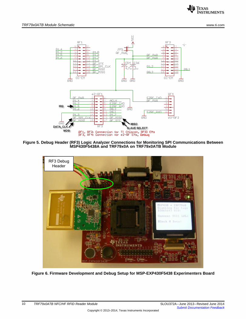
Figure 5. Debug Header (RF3) Logic Analyzer Connections for Monitoring SPI Communications BetweenMSP430F5438A and TRF79x0A on TRF79x0ATB Module
Figure 6. Firmware Development and Debug Setup for MSP-EXP430F5438 Experimenters Board
10 TRF79x0ATB NFC/HF RFID Reader Module SLOU372A–June 2013–Revised June 2014Submit Documentation Feedback
Copyright © 2013–2014, Texas Instruments Incorporated
TRF79 x0ATB
module
connects here
Firmware
Download/Debug
Header
LogicAnalyzer
andDebugHeader
J12
www.ti.com MSP-EXP430F5529 Experimenters Board
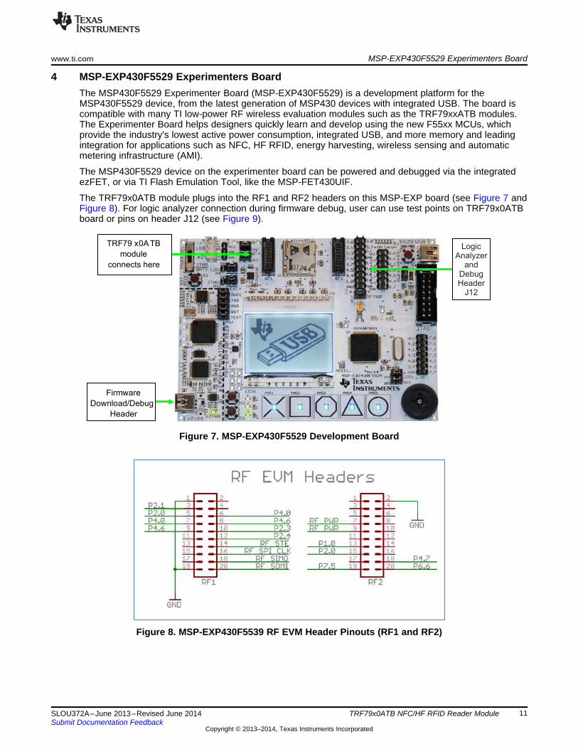
4 MSP-EXP430F5529 Experimenters BoardThe MSP430F5529 Experimenter Board (MSP-EXP430F5529) is a development platform for theMSP430F5529 device, from the latest generation of MSP430 devices with integrated USB. The board iscompatible with many TI low-power RF wireless evaluation modules such as the TRF79xxATB modules.The Experimenter Board helps designers quickly learn and develop using the new F55xx MCUs, whichprovide the industry's lowest active power consumption, integrated USB, and more memory and leadingintegration for applications such as NFC, HF RFID, energy harvesting, wireless sensing and automaticmetering infrastructure (AMI).
The MSP430F5529 device on the experimenter board can be powered and debugged via the integratedezFET, or via TI Flash Emulation Tool, like the MSP-FET430UIF.
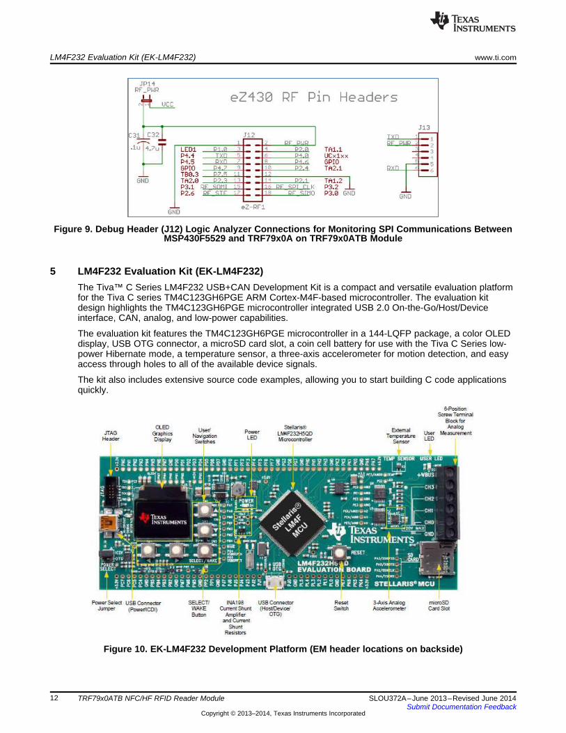
The TRF79x0ATB module plugs into the RF1 and RF2 headers on this MSP-EXP board (see Figure 7 andFigure 8). For logic analyzer connection during firmware debug, user can use test points on TRF79x0ATBboard or pins on header J12 (see Figure 9).
Figure 7. MSP-EXP430F5529 Development Board
Figure 8. MSP-EXP430F5539 RF EVM Header Pinouts (RF1 and RF2)
11SLOU372A–June 2013–Revised June 2014 TRF79x0ATB NFC/HF RFID Reader ModuleSubmit Documentation Feedback
Copyright © 2013–2014, Texas Instruments Incorporated
LM4F232 Evaluation Kit (EK-LM4F232) www.ti.com
Figure 9. Debug Header (J12) Logic Analyzer Connections for Monitoring SPI Communications BetweenMSP430F5529 and TRF79x0A on TRF79x0ATB Module
5 LM4F232 Evaluation Kit (EK-LM4F232)The Tiva™ C Series LM4F232 USB+CAN Development Kit is a compact and versatile evaluation platformfor the Tiva C series TM4C123GH6PGE ARM Cortex-M4F-based microcontroller. The evaluation kitdesign highlights the TM4C123GH6PGE microcontroller integrated USB 2.0 On-the-Go/Host/Deviceinterface, CAN, analog, and low-power capabilities.
The evaluation kit features the TM4C123GH6PGE microcontroller in a 144-LQFP package, a color OLEDdisplay, USB OTG connector, a microSD card slot, a coin cell battery for use with the Tiva C Series low-power Hibernate mode, a temperature sensor, a three-axis accelerometer for motion detection, and easyaccess through holes to all of the available device signals.
The kit also includes extensive source code examples, allowing you to start building C code applicationsquickly.
Figure 10. EK-LM4F232 Development Platform (EM header locations on backside)
12 TRF79x0ATB NFC/HF RFID Reader Module SLOU372A–June 2013–Revised June 2014Submit Documentation Feedback
Copyright © 2013–2014, Texas Instruments Incorporated
www.ti.com DK-LM3S9B96-EM2-TRF7960R ARM Cortex M-3 Development Board
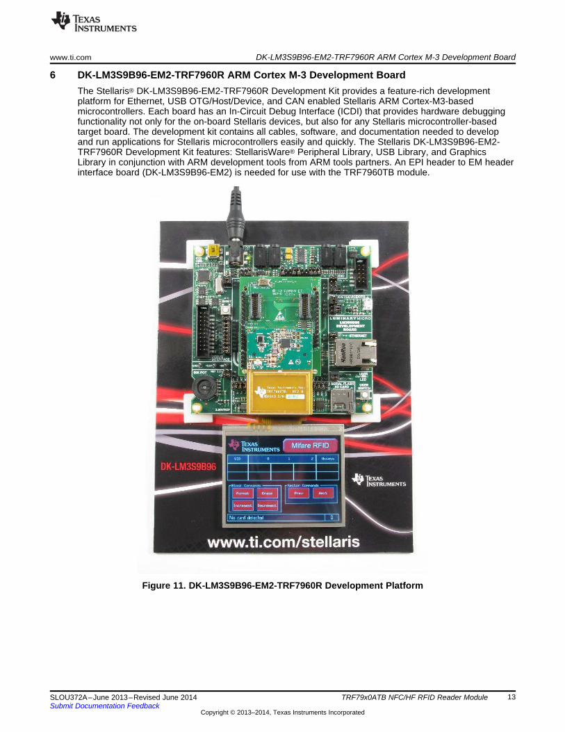
6 DK-LM3S9B96-EM2-TRF7960R ARM Cortex M-3 Development BoardThe Stellaris® DK-LM3S9B96-EM2-TRF7960R Development Kit provides a feature-rich developmentplatform for Ethernet, USB OTG/Host/Device, and CAN enabled Stellaris ARM Cortex-M3-basedmicrocontrollers. Each board has an In-Circuit Debug Interface (ICDI) that provides hardware debuggingfunctionality not only for the on-board Stellaris devices, but also for any Stellaris microcontroller-basedtarget board. The development kit contains all cables, software, and documentation needed to developand run applications for Stellaris microcontrollers easily and quickly. The Stellaris DK-LM3S9B96-EM2-TRF7960R Development Kit features: StellarisWare® Peripheral Library, USB Library, and GraphicsLibrary in conjunction with ARM development tools from ARM tools partners. An EPI header to EM headerinterface board (DK-LM3S9B96-EM2) is needed for use with the TRF7960TB module.
Figure 11. DK-LM3S9B96-EM2-TRF7960R Development Platform
13SLOU372A–June 2013–Revised June 2014 TRF79x0ATB NFC/HF RFID Reader ModuleSubmit Documentation Feedback
Copyright © 2013–2014, Texas Instruments Incorporated
Quick Start www.ti.com
7 Quick Start1. Plug TRF79x0ATB Module into microcontroller development platform of choice.
NOTE: If DK-LM3S9B96 board, remove SDRAM module and replace with DK-LM3S9B96-EM2interface board before attempting to mount TRF79x0ATB module.
2. Apply power.3. Load the base application firmware specific to the platform that you are working with.4. Test for basic communication and functionality.5. Modify and Debug code as desired for specific application or protocol.6. Test for advanced functionality as implemented by modified code.
8 Base Application FirmwareTRF79x0ATB module base application firmware for various Texas Instruments Microcontrollers areavailable here:• MSP430F23xx: http://www.ti.com/litv/zip/sloc203 (Code Composer Studio or IAR)• MSP430F5438A: http://focus.ti.com/docs/toolsw/folders/print/msp-exp430f5438.html• MSP430F5529: http://www.ti.com/tool/nfclink• LM4F232: http://www.ti.com/tool/ekc-lm4f232• LM3S9B96: http://www.ti.com/tool/dk-em2-7960r
14 TRF79x0ATB NFC/HF RFID Reader Module SLOU372A–June 2013–Revised June 2014Submit Documentation Feedback
Copyright © 2013–2014, Texas Instruments Incorporated
1( )
2
2CRES tot
w
alL
here f
w
w p=
=
www.ti.com Mechanical and Physical Information
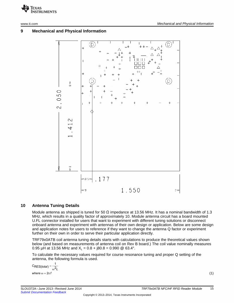
9 Mechanical and Physical Information
10 Antenna Tuning DetailsModule antenna as shipped is tuned for 50 Ω impedance at 13.56 MHz. It has a nominal bandwidth of 1.3MHz, which results in a quality factor of approximately 10. Module antenna circuit has a board mountedU.FL connector installed for users that want to experiment with different tuning solutions or disconnectonboard antenna and experiment with antennas of their own design or application. Below are some designand application notes for users to reference if they want to change the antenna Q factor or experimentfurther on their own in order to serve their particular application directly.
TRF79x0ATB coil antenna tuning details starts with calculations to produce the theoretical values shownbelow (and based on measurements of antenna coil on Rev B board.) The coil value nominally measures0.95 µH at 13.56 MHz and XL = 0.8 + j80.8 = 0.990 @ 63.4°.
To calculate the necessary values required for course resonance tuning and proper Q setting of theantenna, the following formula is used.
(1)
15SLOU372A–June 2013–Revised June 2014 TRF79x0ATB NFC/HF RFID Reader ModuleSubmit Documentation Feedback
Copyright © 2013–2014, Texas Instruments Incorporated
647RPAR = W
1.29R kPAR = W
2R fLQPAR p=
2
RPARQfLp
=
1( ) 2(2 13.56 ) 0.95
145.157( )
CRES totalMHz H
C pFRES total
p m
=
´ ´
=
Antenna Tuning Details www.ti.com
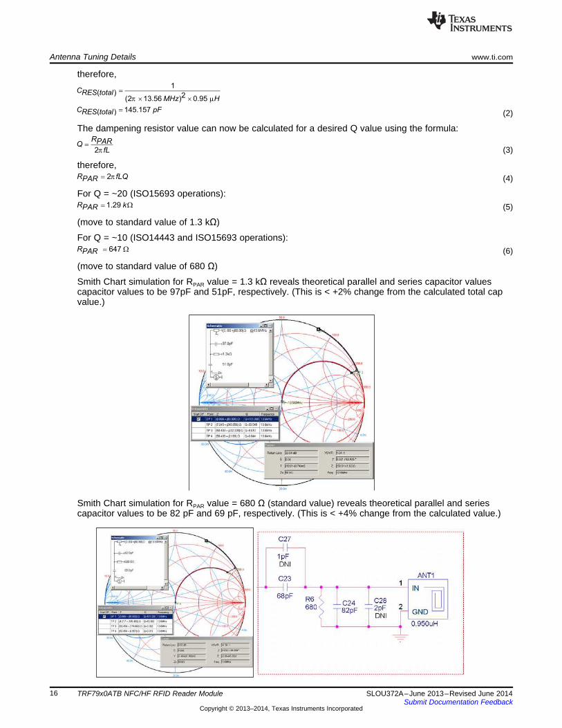
therefore,
(2)
The dampening resistor value can now be calculated for a desired Q value using the formula:
(3)
therefore,(4)
For Q = ~20 (ISO15693 operations):(5)
(move to standard value of 1.3 kΩ)
For Q = ~10 (ISO14443 and ISO15693 operations):(6)
(move to standard value of 680 Ω)
Smith Chart simulation for RPAR value = 1.3 kΩ reveals theoretical parallel and series capacitor valuescapacitor values to be 97pF and 51pF, respectively. (This is < +2% change from the calculated total capvalue.)
Smith Chart simulation for RPAR value = 680 Ω (standard value) reveals theoretical parallel and seriescapacitor values to be 82 pF and 69 pF, respectively. (This is < +4% change from the calculated value.)
16 TRF79x0ATB NFC/HF RFID Reader Module SLOU372A–June 2013–Revised June 2014Submit Documentation Feedback
Copyright © 2013–2014, Texas Instruments Incorporated
Theoretical Capacitance Values for Resonance at Desired Q
97.00E-12
82.00E-12
51.00E-12
68.00E-12
042.00E-12
052.00E-12
062.00E-12
072.00E-12
082.00E-12
092.00E-12
102.00E-12
4 6 8 10 12 14 16 18 20
Q
Ca
pa
cit
an
ce
(in
pF
)
Cpar
Cser
Theoretical Parallel Resistor Value for Desired Q
1.30E+03
680.71E+00
325.00E+00
525.00E+00
725.00E+00
925.00E+00
001.13E+03
001.33E+03
001.53E+03
001.73E+03
4 6 8 10 12 14 16 18 20
Q Value
Oh
ms
Rpar
www.ti.com Antenna Tuning Details
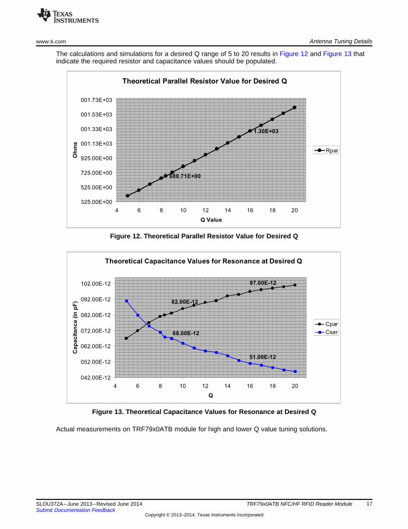
The calculations and simulations for a desired Q range of 5 to 20 results in Figure 12 and Figure 13 thatindicate the required resistor and capacitance values should be populated.
Figure 12. Theoretical Parallel Resistor Value for Desired Q
Figure 13. Theoretical Capacitance Values for Resonance at Desired Q
Actual measurements on TRF79x0ATB module for high and lower Q value tuning solutions.
17SLOU372A–June 2013–Revised June 2014 TRF79x0ATB NFC/HF RFID Reader ModuleSubmit Documentation Feedback
Copyright © 2013–2014, Texas Instruments Incorporated
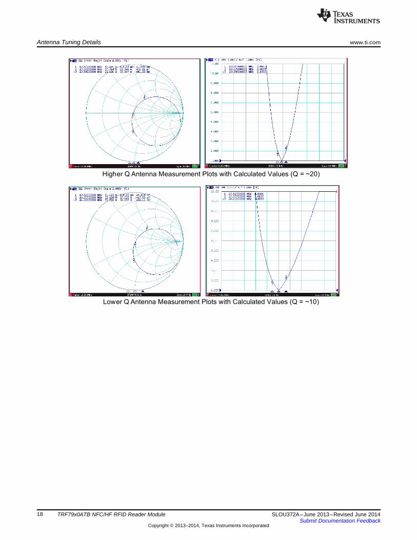
Higher Q Antenna Measurement Plots with Calculated Values (Q = ~20)
Lower Q Antenna Measurement Plots with Calculated Values (Q = ~10)
Antenna Tuning Details www.ti.com
18 TRF79x0ATB NFC/HF RFID Reader Module SLOU372A–June 2013–Revised June 2014Submit Documentation Feedback
Copyright © 2013–2014, Texas Instruments Incorporated
www.ti.com TRF79x0ATB Module Read Ranges
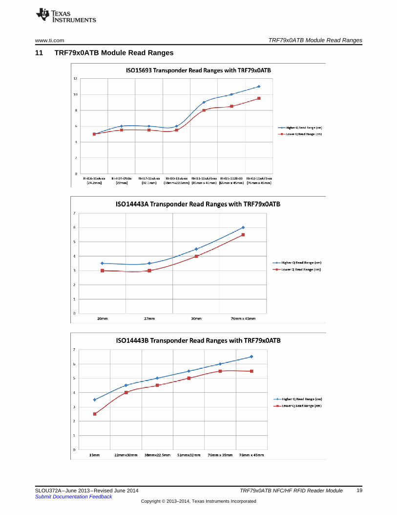
11 TRF79x0ATB Module Read Ranges
19SLOU372A–June 2013–Revised June 2014 TRF79x0ATB NFC/HF RFID Reader ModuleSubmit Documentation Feedback
Copyright © 2013–2014, Texas Instruments Incorporated
References www.ti.com
12 References• TRF7960A Product Page: http://www.ti.com/product/trf7960A• TRF7970A Product Page: http://www.ti.com/product/trf7970A• TPS61222 Product Page: http://www.ti.com/product/tps61222• TRF7960ATB Schematic, BOM and Design files: http://www.ti.com/lit/zip/sloc221• TRF7970ATB Schematic, BOM and Design files: http://www.ti.com/lit/zip/tidc356• LM4F232 Evaluation Kit: http://www.ti.com/tool/ek-lm4f232• TPS61220, TPS61221,TPS61222 Low Input Voltage Step-Up Converter in 6 Pin SC-70 Package Data
Sheet (SLVS776)• MSP430F543x, MSP430F541x Mixed Signal Microcontroller Data Sheet (SLAS612)• TRF7960A Multi-Protocol Fully Integrated 13.56-MHz RFID Reader/Writer IC Data Manual (SLOS732)• TRF7970A Multi-Protocol Fully Integrated 13.56-MHz RFID/Near Field Communication (NFC)
Transceiver IC Data Manual (SLOS743)• MSP-EXP430F5529 Experimenter Board User's Guide (SLAU330)• MSP-EXP430F5438 Experimenter Board User's Guide (SLAU263)• Stellaris® LM3S9B96 Development Kit User's Manual (SPMA036)• TI ISO15693/ISO18000-3 Inlays/Tags Parametric Search
http://www.ti.com/lsds/ti/wireless_connectivity/nfc_rfid/products.page#o7=Transponders, Inlays andDies
• Samtec Header and Mate Information– SFM: https://www.samtec.com/technical-specifications/Default.aspx?seriesMaster=SFM– TFM: https://www.samtec.com/technical-specifications/Default.aspx?seriesMaster=TFM
• Smith Chart Simulation Tool (licensed copy): http://www.fritz.dellsperger.net/
20 TRF79x0ATB NFC/HF RFID Reader Module SLOU372A–June 2013–Revised June 2014Submit Documentation Feedback
Copyright © 2013–2014, Texas Instruments Incorporated
www.ti.com Revision History
Revision History
Changes from Original (June 2013) to A Revision ......................................................................................................... Page
• Corrected links in Section 12........................................................................................................... 20
NOTE: Page numbers for previous revisions may differ from page numbers in the current version.
21SLOU372A–June 2013–Revised June 2014 Revision HistorySubmit Documentation Feedback
Copyright © 2013–2014, Texas Instruments Incorporated
IMPORTANT NOTICE
Texas Instruments Incorporated and its subsidiaries (TI) reserve the right to make corrections, enhancements, improvements and otherchanges to its semiconductor products and services per JESD46, latest issue, and to discontinue any product or service per JESD48, latestissue. Buyers should obtain the latest relevant information before placing orders and should verify that such information is current andcomplete. All semiconductor products (also referred to herein as “components”) are sold subject to TI’s terms and conditions of salesupplied at the time of order acknowledgment.TI warrants performance of its components to the specifications applicable at the time of sale, in accordance with the warranty in TI’s termsand conditions of sale of semiconductor products. Testing and other quality control techniques are used to the extent TI deems necessaryto support this warranty. Except where mandated by applicable law, testing of all parameters of each component is not necessarilyperformed.TI assumes no liability for applications assistance or the design of Buyers’ products. Buyers are responsible for their products andapplications using TI components. To minimize the risks associated with Buyers’ products and applications, Buyers should provideadequate design and operating safeguards.TI does not warrant or represent that any license, either express or implied, is granted under any patent right, copyright, mask work right, orother intellectual property right relating to any combination, machine, or process in which TI components or services are used. Informationpublished by TI regarding third-party products or services does not constitute a license to use such products or services or a warranty orendorsement thereof. Use of such information may require a license from a third party under the patents or other intellectual property of thethird party, or a license from TI under the patents or other intellectual property of TI.Reproduction of significant portions of TI information in TI data books or data sheets is permissible only if reproduction is without alterationand is accompanied by all associated warranties, conditions, limitations, and notices. TI is not responsible or liable for such altereddocumentation. Information of third parties may be subject to additional restrictions.Resale of TI components or services with statements different from or beyond the parameters stated by TI for that component or servicevoids all express and any implied warranties for the associated TI component or service and is an unfair and deceptive business practice.TI is not responsible or liable for any such statements.Buyer acknowledges and agrees that it is solely responsible for compliance with all legal, regulatory and safety-related requirementsconcerning its products, and any use of TI components in its applications, notwithstanding any applications-related information or supportthat may be provided by TI. Buyer represents and agrees that it has all the necessary expertise to create and implement safeguards whichanticipate dangerous consequences of failures, monitor failures and their consequences, lessen the likelihood of failures that might causeharm and take appropriate remedial actions. Buyer will fully indemnify TI and its representatives against any damages arising out of the useof any TI components in safety-critical applications.In some cases, TI components may be promoted specifically to facilitate safety-related applications. With such components, TI’s goal is tohelp enable customers to design and create their own end-product solutions that meet applicable functional safety standards andrequirements. Nonetheless, such components are subject to these terms.No TI components are authorized for use in FDA Class III (or similar life-critical medical equipment) unless authorized officers of the partieshave executed a special agreement specifically governing such use.Only those TI components which TI has specifically designated as military grade or “enhanced plastic” are designed and intended for use inmilitary/aerospace applications or environments. Buyer acknowledges and agrees that any military or aerospace use of TI componentswhich have not been so designated is solely at the Buyer's risk, and that Buyer is solely responsible for compliance with all legal andregulatory requirements in connection with such use.TI has specifically designated certain components as meeting ISO/TS16949 requirements, mainly for automotive use. In any case of use ofnon-designated products, TI will not be responsible for any failure to meet ISO/TS16949.
Products ApplicationsAudio www.ti.com/audio Automotive and Transportation www.ti.com/automotiveAmplifiers amplifier.ti.com Communications and Telecom www.ti.com/communicationsData Converters dataconverter.ti.com Computers and Peripherals www.ti.com/computersDLP® Products www.dlp.com Consumer Electronics www.ti.com/consumer-appsDSP dsp.ti.com Energy and Lighting www.ti.com/energyClocks and Timers www.ti.com/clocks Industrial www.ti.com/industrialInterface interface.ti.com Medical www.ti.com/medicalLogic logic.ti.com Security www.ti.com/securityPower Mgmt power.ti.com Space, Avionics and Defense www.ti.com/space-avionics-defenseMicrocontrollers microcontroller.ti.com Video and Imaging www.ti.com/videoRFID www.ti-rfid.comOMAP Applications Processors www.ti.com/omap TI E2E Community e2e.ti.comWireless Connectivity www.ti.com/wirelessconnectivity
Mailing Address: Texas Instruments, Post Office Box 655303, Dallas, Texas 75265Copyright © 2014, Texas Instruments Incorporated