Embed Size (px)
Citation preview
NTN9176_ASTRO® XTS™
Tri-Chemistry Vehicular ChargerUser Guide
All batteries can cause property damage and/or bodily injury such as burns if a conductive material such as jewelry, keys or beaded chains touches exposed terminals. The material may complete an electrical circuit (short circuit) and become quite hot. Exercise care in handling any charged battery, particularly when placing it inside a pocket, purse or other container with metal objects.
Do not replace or charge batteries in potentially explosive atmosphere. Contact sparking may occur while installing or removing batteries and cause an explosion.
Due to the risk of electrical shock or other physical injury, never insert your hands into the charger pocket.
Warning For Vehicles Equipped With an Airbag
An airbag inflates with great force. DO NOT place objects, including communication equipment, in the area over the airbag or in the airbag deployment area. If the communication equipment is improperly installed and the airbag inflates, this could cause serious injury.
• Installation of vehicle communication equipment should be performed by a professional installer/technician qualified in the requirements for such installations. An airbag’s size, shape, and deployment area can vary by vehicle make, model, and front compartment configuration (e.g., bench seat vs. bucket seats).
• Contact the vehicle manufacturer’s corporate headquarters, if necessary, for specific airbag information for the vehicle make, model, and front compartment configuration involved in your communication equipment installation.
Important Note: If a vehicular repeater is installed, verify operation of the repeater before leaving the vicinity of the vehicle.
!W A R N I N G
!
!W A R N I N G
!
!W A R N I N G
!
!W A R N I N G
!
1
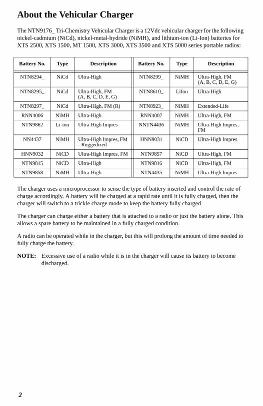
About the Vehicular ChargerThe NTN9176_ Tri-Chemistry Vehicular Charger is a 12Vdc vehicular charger for the following nickel-cadmium (NiCd), nickel-metal-hydride (NiMH), and lithium-ion (Li-Ion) batteries for XTS 2500, XTS 1500, MT 1500, XTS 3000, XTS 3500 and XTS 5000 series portable radios:
The charger uses a microprocessor to sense the type of battery inserted and control the rate of charge accordingly. A battery will be charged at a rapid rate until it is fully charged, then the charger will switch to a trickle charge mode to keep the battery fully charged.
The charger can charge either a battery that is attached to a radio or just the battery alone. This allows a spare battery to be maintained in a fully charged condition.
A radio can be operated while in the charger, but this will prolong the amount of time needed to fully charge the battery.
NOTE: Excessive use of a radio while it is in the charger will cause its battery to become discharged.
Battery No. Type Description Battery No. Type Description
NTN8294_ NiCd Ultra-High NTN8299_ NiMH Ultra-High, FM (A, B, C, D, E, G)
NTN8295_ NiCd Ultra-High, FM (A, B, C, D, E, G)
NTN8610_ LiIon Ultra-High
NTN8297_ NiCd Ultra-High, FM (R) NTN8923_ NiMH Extended-Life
RNN4006 NiMH Ultra-High RNN4007 NiMH Ultra-High, FM
NTN9862 Li-ion Ultra-High Impres NNTN4436 NiMH Ultra-High Impres, FM
NN4437 NiMH Ultra-High Impres, FM - Ruggedized
HNN9031 NiCD Ultra-High Impres
HNN9032 NiCD Ultra-High Impres, FM NTN9857 NiCD Ultra-High, FM
NTN9815 NiCD Ultra-High NTN9816 NiCD Ultra-High, FM
NTN9858 NiMH Ultra-High NTN4435 NiMH Ultra-High Impres
2
3
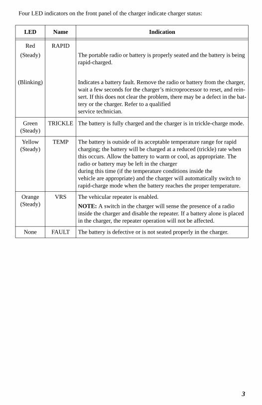
Four LED indicators on the front panel of the charger indicate charger status:
LED Name Indication
Red(Steady)
(Blinking)
RAPIDThe portable radio or battery is properly seated and the battery is being rapid-charged.
Indicates a battery fault. Remove the radio or battery from the charger, wait a few seconds for the charger’s microprocessor to reset, and rein-sert. If this does not clear the problem, there may be a defect in the bat-tery or the charger. Refer to a qualified service technician.
Green (Steady)
TRICKLE The battery is fully charged and the charger is in trickle-charge mode.
Yellow (Steady)
TEMP The battery is outside of its acceptable temperature range for rapid charging; the battery will be charged at a reduced (trickle) rate when this occurs. Allow the battery to warm or cool, as appropriate. The radio or battery may be left in the charger during this time (if the temperature conditions inside the vehicle are appropriate) and the charger will automatically switch to rapid-charge mode when the battery reaches the proper temperature.
Orange (Steady)
VRS The vehicular repeater is enabled.NOTE: A switch in the charger will sense the presence of a radio inside the charger and disable the repeater. If a battery alone is placed in the charger, the repeater operation will not be affected.
None FAULT The battery is defective or is not seated properly in the charger.
Securing the Radio in the Vehicular ChargerThe NTN9176_ Vehicular Charger is equipped with a feature that reduces the risk of a portable radio (or battery alone) in the pocket from becoming dislodged and potentially hazardous in the event of a vehicular collision. Operators are instructed to follow the vehicular charger installation instructions and to use this feature as follows:
1. Anyone intending to operate the vehicular charger is advised to locate and become familiar with:
• the stationary leather strap that protrudes from the lower edge of the pocket opening,
• the cord, and
• the snappable leather latch.
The buttons on the latch and housing top are designed to mate with the snap on the strap.
2. When the vehicular charger is not in use, the latch may be snapped to the strap to stow it. The unit is shipped from the factory in this configuration.
3. To use the vehicular charger, insert the portable radio or battery alone into the charger pocket.
4. Unsnap the leather latch from the strap.
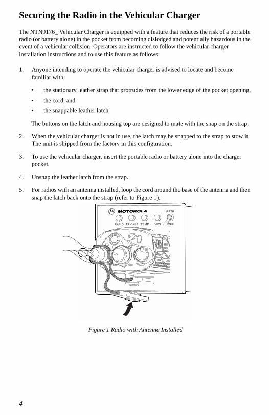
5. For radios with an antenna installed, loop the cord around the base of the antenna and then snap the latch back onto the strap (refer to Figure 1).
Figure 1 Radio with Antenna Installed
RAPID TRICKLE TEMP VRS OFF
RPTR
4
— or —
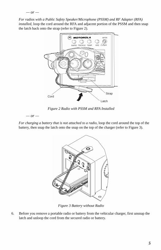
For radios with a Public Safety Speaker/Microphone (PSSM) and RF Adapter (RFA) installed, loop the cord around the RFA and adjacent portion of the PSSM and then snap the latch back onto the strap (refer to Figure 2).
Figure 2 Radio with PSSM and RFA Installed
— or —
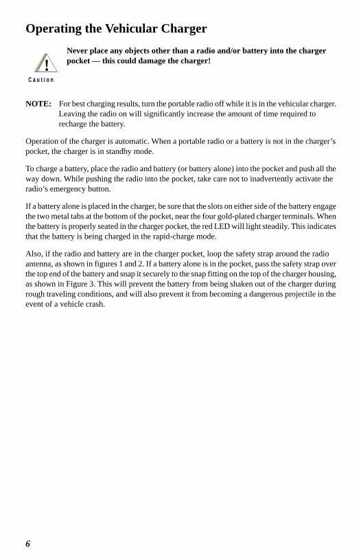
For charging a battery that is not attached to a radio, loop the cord around the top of the battery, then snap the latch onto the snap on the top of the charger (refer to Figure 3).
Figure 3 Battery without Radio
6. Before you remove a portable radio or battery from the vehicular charger, first unsnap the latch and unloop the cord from the secured radio or battery.
Cord
Latch
Strap
RAPID TRICKLE TEMP VRS OFF
RPTR
5
Operating the Vehicular ChargerNever place any objects other than a radio and/or battery into the charger pocket — this could damage the charger!
NOTE: For best charging results, turn the portable radio off while it is in the vehicular charger. Leaving the radio on will significantly increase the amount of time required to recharge the battery.
Operation of the charger is automatic. When a portable radio or a battery is not in the charger’s pocket, the charger is in standby mode.
To charge a battery, place the radio and battery (or battery alone) into the pocket and push all the way down. While pushing the radio into the pocket, take care not to inadvertently activate the radio’s emergency button.
If a battery alone is placed in the charger, be sure that the slots on either side of the battery engage the two metal tabs at the bottom of the pocket, near the four gold-plated charger terminals. When the battery is properly seated in the charger pocket, the red LED will light steadily. This indicates that the battery is being charged in the rapid-charge mode.
Also, if the radio and battery are in the charger pocket, loop the safety strap around the radio antenna, as shown in figures 1 and 2. If a battery alone is in the pocket, pass the safety strap over the top end of the battery and snap it securely to the snap fitting on the top of the charger housing, as shown in Figure 3. This will prevent the battery from being shaken out of the charger during rough traveling conditions, and will also prevent it from becoming a dangerous projectile in the event of a vehicle crash.
!C a u t i o n
6
Specifications
InstallationMounting hardware supplied includes a trunnion bracket for mounting the unit below the vehicle dashboard, on the floor, or on the wall, and a cable for connection to the vehicle’s electrical system. The bracket enables the charger to be pivoted to a position that offers the best security to the portable radio during rough driving conditions.
Install the vehicular charger as follows:
1. Plan the location for mounting the charger. Identify the routing paths for the cable and verify that the cable length is adequate. Also check the mounting penetrations required. On most vehicles, it is necessary to penetrate the firewall to reach the battery. Check the opposite side of the firewall for cable clearance before drilling holes. Protect the cable where it passes through the firewall by use of appropriate rubber grommets (not supplied) or other protective measures.
Survey the firewall for existing holes occupied by vehicle wire harnesses. Often there is an opportunity to route other cables using the same path. Because of the wide variation in vehicle design, these instructions may be modified to suit each particular installation.
A properly installed unit will minimize service calls and equipment downtime. Consider the following guidelines when planning the installation:
• DO consider a mounting location which will allow the unit to be mounted at a 45-degree up angle. This angle provides operational convenience and physical security for the portable radio under rough traveling conditions.
• DO use heat shrink tubing on all splices.
Input Voltage: 11-16Vdc
13.8V Nominal
Maximum Charge Rate:
NiCd:NiMH:Li-Ion:
1250mA Rapid Charge, 30mA Trickle Charge1000mA Rapid Charge, 30mA Trickle Charge1210mA Rapid Charge, 30mA Trickle Charge
Rapid Charge Cycle: 3 hours typical, depending upon battery type, capacity and state of charge.
Size: 3.7" W x 3.7" H x 5.3" D
Weight: 2 Lb (approx.)
Operating Temperature:
NiCd and NiMH:Li-Ion:
+41°F to +122°F (+5°C to +50°C)+41°F to +113°F (+5°C to +45°C)
Inline Fuses: AGC 2 Amp and AGC 0.25 Amp
7
• DO ensure that the cable is not placed under stress, is not exposed to weather, and is not subjected to damage due to engine heat.
• DO retain the in-line cable fuse when trimming the cable to fit. Locate the in-line fuse as close as practical to the supply voltage connection.
• DO check the opposite sides of all mounting surfaces before drilling, to insure that there are no obstructions, such as vehicle wiring and fluid lines.
• DON’T attach the unit to any part of the vehicle that is not rigid or is subject to excessive vibration.
• DON’T install the unit in an area where rain or snow can easily get into it, such as next to a vehicle window which may be left open.
• DON’T install the unit in a location where it could interfere with the vehicle’s operator or operating controls.
• DON’T dress the cable over sharp edges that could cause wear or tearing of cable insulation.
• DON’T install the unit in a location where it may be difficult for the operator to reach.
• DON’T install the unit where it may interfere with the vehicle safety air bag deployment.
• DON’T install the unit where the LED indicators and switch may become physically damaged.
2. Using the trunnion bracket as a template, mark the mounting surface drilling locations. It is recommended that at least four screws be used, with 1/4 inch being the preferred fastener diameter.
3. Re-verify that there are no wires, fluid lines, or other obstructions on the other side of the mounting location, and drill appropriate sized holes for the mounting screws to be used.
4. Referring to Figure 4, mount the bracket using appropriate screws, washers, lock washers, and nuts.
5. Insert the unit into the bracket, and install the threaded knobs into the housing, as shown.
8
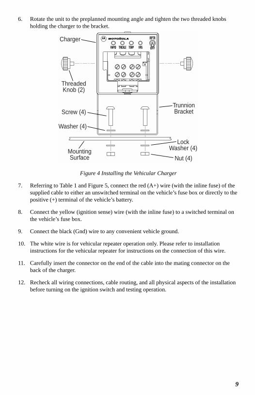
6. Rotate the unit to the preplanned mounting angle and tighten the two threaded knobs holding the charger to the bracket.
.
Figure 4 Installing the Vehicular Charger
7. Referring to Table 1 and Figure 5, connect the red (A+) wire (with the inline fuse) of the supplied cable to either an unswitched terminal on the vehicle’s fuse box or directly to the positive (+) terminal of the vehicle’s battery.
8. Connect the yellow (ignition sense) wire (with the inline fuse) to a switched terminal on the vehicle’s fuse box.
9. Connect the black (Gnd) wire to any convenient vehicle ground.
10. The white wire is for vehicular repeater operation only. Please refer to installation instructions for the vehicular repeater for instructions on the connection of this wire.
11. Carefully insert the connector on the end of the cable into the mating connector on the back of the charger.
12. Recheck all wiring connections, cable routing, and all physical aspects of the installation before turning on the ignition switch and testing operation.
Charger
Screw (4)
Washer (4)
MountingSurface
ThreadedKnob (2)
TrunnionBracket
LockWasher (4)
Nut (4)
9
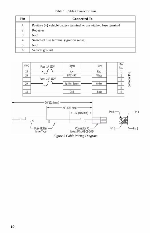
Figure 5 Cable Wiring Diagram
Table 1 Cable Connector Pins
Pin Connected To
1 Positive (+) vehicle battery terminal or unswitched fuse terminal2 Repeater3 N/C4 Switched fuse terminal (ignition sense)5 N/C6 Vehicle ground
AWG
1820
20
18
Signal
A +PAC - RT
Ignition Sense
Gnd
Color
RedWhite
Yellow
Black
123456
PinNo.Fuse 2A 250V
Fuse .25A 250V
Conn
ecto
r P-1
16¨ (406 mm)
36¨ (914 mm)
Fuse HolderInline Type
Connector P1Molex P/N: 03-09-1064
Pin 4
Pin 2 Pin 1
Pin 6
MAEPF-27085-O
21¨ (533 mm)
10
Warranty ReplacementMotorola, Inc. (“Motorola”) warrants the Vehicular Charger against defects in material and workmanship under normal use and service for a period of one (1) year from shipment. Items will be repaired or replaced free of charge for the full warranty period. Freight charges to and from the place where warranty replacement is provided shall be the Customer’s responsibility.
This warranty does NOT cover defects or damages to the Vehicular Charger resulting from (a) use in a manner other than normal operation as specified in the instruction manual; (b) misuse, accident, or neglect; (c) improper disassembly, testing, operation, maintenance, installation, adjustment, alteration, repair, or any modification by the Customer or any person without prior written consent of Motorola.
If repair or replacement under warranty becomes necessary, the manufacturer’s facility, TPL Communications, will serve as the repair depot. Call to request a Return Authorization Number and return the product to the following address (including a brief description of the problem, a return address, daytime telephone number and proof of purchase):
TPL Communications3370 San Fernando Rd., Unit 206Los Angeles CA 90065(323) 256-3000Email: [email protected]
Instruction Manual OrderingThis manual has an associated Instruction Manual, Motorola Part No. 6881093C12, which contains appropriate information for servicing the vehicular charger. This manual can be ordered from:
Motorola Inc.United States and Canada Aftermarket Products DivisionAttention: Order Processing7230 Parkway DriveLandover, MD 21076
Call: 1-800-422-42101-800-826-1913 (For Federal Government Orders)1-847-538-8023 (International Orders)
FAX: 847-538-8198 (Domestic)847-576-3023 (International)
11

6881093C13-A
*6881093C13*
MOTOROLA, the Stylized M Logo, and ASTRO are registered
in the U.S. Patent and Trademark Office. All other product or
service names are the property of their respective owners.
© Motorola, Inc. 2004.
All rights reserved. Printed in U.S.A.
Motorola, Inc.
8000 West Sunrise Boulevard
Ft. Lauderdale, FL 33322