Embed Size (px)
Citation preview
Universidade de São Paulo
2014-09-23
Tribological performance of textured surfaces
in the piston ring/liner contact using the elrod-
adams model Congreso sobre Métodos Numéricos y sus Aplicaciones, 21, 2014, Bariloche.http://www.producao.usp.br/handle/BDPI/48436
Downloaded from: Biblioteca Digital da Produção Intelectual - BDPI, Universidade de São Paulo
Biblioteca Digital da Produção Intelectual - BDPI
Departamento de Matemática Aplicada e Estatística - ICMC/SME Comunicações em Eventos - ICMC/SME
TRIBOLOGICAL PERFORMANCE OF TEXTURED SURFACES IN
THE PISTON RING/LINER CONTACT USING THE ELROD-ADAMS
MODEL
Hugo M. Checoa, Alfredo Jaramilloa, Mohammed Jaib and Gustavo C. Buscagliaa
aInst. de Ciências Matemáticas e de Computação, Universidade de São Paulo, 13560-970 São Carlos,
Brazil, http://http://www.icmc.usp.br
bInstitut Camille Jordan, INSA de Lyon , 69621 Villeurbanne, France, http://http://math.univ-lyon1.fr
Keywords: Friction reduction, textured surfaces, piston ring, Elrod-Adams model.
Abstract. The possibility of improving the performance of lubricated surfaces through surface textur-ing has been a topic of intense research in the latest years. Considerable efforts in both experimentaland numerical works have been made to study the effects of micro-textures in load capacity, friction andwear. In the industry it has been known for a long time that some texturing is required in the liners ofcombustion engines to avoid stiction with the piston rings. The numerical simulation of that problemposes a challenge in modeling the intervening phenomena (cavitation, starvation, ring dynamics) andsolving it efficiently.
In this work we present numerical simulations of the piston ring/liner problem in the hydrodynamiclubrication regime using the Elrod-Adams model and a mass-conserving algorithm. Realistic values areassumed for the parameters defining the problem. The formation of cavitation bubbles and its relationwith the load-carrying capacity, friction and clearance is analyzed by considering different texture con-figurations and shapes in one-dimensional tests. Afterwards, two-dimensional dimpled surfaces are sim-ulated for more than a hundred different texture configurations in the hydrodynamic lubrication regimefor several Stribeck numbers. A robust code accelerated by means of a multigrid implementation al-lowed the realization of this extensive study. Results show that friction and wear reduction are attainableby virtue of dimples of the size of the contact, although the gain decreases or disappears as the mixedlubrication regime is approached.
Mecánica Computacional Vol XXXIII, págs. 129-145 (artículo completo)Graciela Bertolino, Mariano Cantero, Mario Storti y Federico Teruel (Eds.)
San Carlos de Bariloche, 23-26 Setiembre 2014
Copyright © 2014 Asociación Argentina de Mecánica Computacional http://www.amcaonline.org.ar
1 INTRODUCTION
Modifying the contacting surfaces in lubricated pairs in order to improve its tribologicalperformance has been a long-term practice. In the specific case of cylinder liners of combustionengines the abrasive machining process known as honing is used to generate a cross-hatchedfinish to ensure proper lubrication, as well as to avoid deleterious effects such as stiction.
The availability of new microengineering techniques such as Laser Surface Texturing (LST)(Etsion (2005)) allowing tailor-made surfaces to be produced, has made the topic of the optimalgeometry for a certain application the subject of intensive research in the last years.
There seems to be a general consensus for the beneficial effects of textures (dimples andmicro-grooves) in devices such as thrust bearings, where conformal contact (parallel or almostparallel surfaces) is involved. This is shown in Mishra and Polycarpou (2011), Ramesh et al.(2013), Yuan et al. (2011), Wang et al. (2006), Bifeng et al. (2012) and Cho and Park (2011).On the other hand, opposite results have been reported in a few cases (Pettersson and Jacobson(2007); Kovalchenko et al. (2005)).
Some applications, as is the case of the piston ring/liner contact, do not fall in the previouscategory. In the non-conformal situation, the experimental study of Costa and Hutchings (2007)showed that larger curvature radius in cylinder against textured flat surface tests led to a benefitin texturing, while smaller radii had the opposite effect. Gadeschi et al. (2012) studied the effectof the curvature on minimum film thickness, load capacity, friction force and friction coefficientfor barrel shaped textured rings using the Reynolds equation with Gümbel boundary conditionfor cavitation. Similar conclusions were reached: for large ring curvatures the textured caseswould perform worse than their untextured counterparts, and vice-versa. These findings arealso supported by Kovalchenko et al. (2011), Ali et al. (2012), Tomanik (2008) and Dobricaet al. (2010).
Most works addressing textured surfaces in the piston ring/liner problem consider the tex-tures on the ring (Etsion and Sher (2009); Qiu and Khonsari (2011); Gadeschi et al. (2012)).It seems preferable to put textures on the liner instead of the ring, as textures on the ring areexpected to last only the break-in period. LST on the bore is expected to last the engine lifetime(Tomanik (2013)). Besides, this also allows to texture only selected parts of the engine cycle.
Few numerical works (Organisciak and Cavallaro (2005); Tomanik (2013)) consider textureson the liner, and even fewer contemplate that the dynamical behavior of the ring must be takeninto account (Buscaglia et al. (2010); Checo et al. (2014)). Textures on the ring are stationaryand thus the ring reaches a equilibrium position, stabilizing at the point where equilibrium offorces take place. When textures are set on the liner they are moving through the domain. Thepassing of a texture under the ring causes a oscillatory motion, hence the simulation must betransient in this case, incorporating the rigid-body dynamics.
In this article, the piston ring/liner problem with textures on the liner will be addressed,taking into account the ring dynamics. The mass-conserving Elrod-Adams model (Elrod andAdams (1974)) is used to model cavitation in lubrication. Mass-conservation has been provennumerically (Ausas et al. (2009a)) and experimentally (Zhang and Meng (2012)) to be essentialto achieve meaningful physical results. Although the piston velocity and loads on the rings varyalong an engine cycle, constant values for those parameters are considered, corresponding tothose of mid-stroke of a four-stroke combustion engine. Only the hydrodynamic lubricationregime is studied, by imposing a sufficiently low load on the ring.
This paper is organized as follows: in Section 2 the mathematical model is described. Sec-tion 3 presents the numerical method. A finite volume discretization is employed to solvethe Elrod-Adams model, with convergence acceleration through a multigrid method. Multi-grid performance results as well as mesh-converged numerical simulations for one and two-
H.M. CHECO, A. JARAMILLO, M. JAI, G.C. BUSCAGLIA130
Copyright © 2014 Asociación Argentina de Mecánica Computacional http://www.amcaonline.org.ar

Ring gap Computational domain
Compression rings
Oil control ring
Liner
Textures
(a)
Z(t)
GasGas
Fluid
h(x,t)e
Motion
Textured runner
Pad
W a
ℓ
Ω0 Σ Ω+Σ Ω0
hLW h
R
x3
x1
(b)
Figure 1: Figure (a) shows a scheme of a ring pack placed in the piston. The computational domain is bounded bya red rectangle while figure (b) depicts a section along the piston’s direction of motion, with the forces acting onit.
dimensional textures are shown and discussed in Section 4. The former set of tests (one-dimensional) thoroughly explores sinusoidal textures for two ring curvature radius and fixedvelocity and loads on the ring. The latter considers dimples with dimensions inspired in thoseproduced by LST for 10 ring curvature radius, from 2 mm to 1024 mm. Finally, conclusionsare drawn in Section 5.
2 MODEL
A very thin stripe of the liner surface in the piston movement direction is chosen as thecomputational domain, which is shown in fig. 1. The direction of the motion of the piston ischosen to be x1, while the runner is assumed to coincide with the x1 − x2 plane. The frameof reference is fixed on the ring and thus we assume that the liner moves with velocity u (thepiston is moving with velocity −u in a frame attached to the liner).
Textures on the liner are given by a function x3 = −hL(x1, x2) ≤ 0 (hL(x1, x2)=0 for theuntextured liner). They are periodic in both x1 and x2 directions, therefore 0 < x2 < w,with w large enough to contain one texture period. In the x1 direction the domain extent isxℓ < x1 < xr.
A single ring of length ℓ is considered with profile hU(x1, x2) satisfying min(x1,x2) hU(x1, x2) =0. Its analytical expression corresponds to an arc of circumference of radius R located inxℓ < a ≤ x1 ≤ b < xr. A uniform thickness e is assumed outside the pad’s location. Hence,we have for the gap between the liner and the ring:
h(x1, x2, t) =
hL(x1 − u t, x2) + hU(x1, x2) + Z(t) if a < x1 < bhL(x1 − u t, x2) + e otherwise
(1)
where Z(t) denotes the vertical distance between the pad and the x1 − x2 plane.Besides the geometrical features we also need to model:
1. The fluid dynamics,
2. The ring dynamics (forces acting on it).
Mecánica Computacional Vol XXXIII, págs. 129-145 (2014) 131
Copyright © 2014 Asociación Argentina de Mecánica Computacional http://www.amcaonline.org.ar
2.1 Thin film fluid dynamics with cavitation
The very thin gap between the ring and liner allows the use of the lubrication approxi-mation (Reynolds equation). Due to the convergent-divergent geometry of the ring/texturedliner contact and to the movement of the ring in its placement cavitation takes place. In thiswork we adopt the well-known Elrod-Adams model (Elrod and Adams (1974)) which incor-porates into a single formulation the Reynolds equation for the pressurized region and theJacobsson-Floberg-Olsson boundary conditions for cavitation. Comparison between resultswith this mass-conserving model and experiments show excellent agreement (Zhang and Meng(2012)).
The model postulates the computation of two fields, p and θ, which correspond to the hydro-dynamic pressure and to an auxiliary saturation-like variable, respectively, that (weakly) satisfythe equation
∇ ·
(
h3
12µ∇p
)
=u(t)
2
∂ hθ
∂x1
+∂ hθ
∂t(2)
under the complementarity conditions
p > 0 ⇒ θ = 1θ < 1 ⇒ p = 00 ≤ θ ≤ 1
(3)
where µ is the viscosity of the lubricant.Initial conditions for θ and p are provided. A constant film thickness of lubricant dlub is
assumed upstream of the ring, which amount to imposing θ = dlub/h at the boundary of thecomputational domain. At x2 = 0 and x2 = w proper boundary conditions are set to enforceperiodicity in the x2 direction.
At each instant the domain spontaneously divides into a pressurized region, Ω+, wherep > 0, and a cavitated region, Ω0, where the film is not full (θ < 1, see figure 1). At theboundary between Ω+ and Ω0, the so-called cavitation boundary Σ, the Elrod-Adams modelautomatically enforces mass-conservation.
2.2 Ring dynamics
Several forces act on the ring in the x3 direction. Here we focus in two of them:
1. The pre-stress force W a: pointed downwards (i.e.; along −x3) and is assumed constant.Comes from the elastic response of the ring to the deformation needed to fit its placement;
2. The hydrodynamic force W h: originates from the pressure p(x1, x2, t) that develops inthe ring/liner bearing:
W h(t) =1
w
∫ w
0
∫ b
a
p(x1, x2, t) dx1 dx2 (4)
Notice that this two forces are forces per unit width. Other two relevant forces acting onit are the contact force due to interaction between the surface’s asperities and the one comingfrom pressure of the combustion gases acting on the back part of the ring. Only constant loadson the ring in the hydrodynamic lubrication regime will be assessed in this work, and hencethese last two forces won’t be considered.
H.M. CHECO, A. JARAMILLO, M. JAI, G.C. BUSCAGLIA132
Copyright © 2014 Asociación Argentina de Mecánica Computacional http://www.amcaonline.org.ar
We assume no tilting of the ring and then the ring dynamics is given by Newton’s secondlaw in the x3 direction:
md2Z
dt2= −W a(t) +W h(t) (5)
where m is the ring’s linear mass. This is supplemented with initial conditions for Z and Z ′
at t = 0.
2.3 Non-dimensionalization
Three fundamental scales are chosen:
• U for velocity;
• L for lengths in the x1 − x2 plane and also for R;
• H for lengths in the x3 direction.
Their values are set to U=10 m/s, L = ℓ= 10−3m (equal to the ring’s length) and H=1 µm. The lubricant viscosity is set to µ= 0.004 Pa.s A detailed description of the non-dimensionalization can be seen in Checo et al. (2014).
Upon non-dimensionalization of all variables (non-dimensional variables will be kept fromthis point on), the complete non-dimensional mathematical problem to be solved reads:
“Find trajectory Z(t), and fields p(t), θ(t), defined on Ω = (xℓ, xr)× (0, w) and periodic inx2, satisfying
Z(0) = Z0, Z ′(0) = V0,θ(xℓ, x2, t) = dlub/h(xℓ, x2, t) ∀x2 ∈ (0, w)p > 0 ⇒ θ = 1θ < 1 ⇒ p = 00 ≤ θ ≤ 1
(6)
and
md2Z
dt2= −W a +W h(t) (7)
∇ ·(
h3∇p)
= u∂ hθ
∂x1
+ 2∂ hθ
∂t(8)
where
h(x1, x2, t) =
hL(x1 − u t, x2) + hU(x1, x2) + Z(t) if a < x1 < bhL(x1 − u t, x2) + e otherwise
, (9)
W h(t) =1
w
∫ b
a
∫ w
0
p(x1, x2, t) dx1 dx2 , (10)
and the functions hL(x1, x2) and hU(x1, x2) are known explicitly.”
3 NUMERICAL METHOD
A finite volume, mass-conserving method with upwinding discretization of the Couette fluxand centered discretization of the Poiseuille flux is employed in a cartesian mesh to solve equa-tion (8), as done by Ausas et al. (2009a). The rectangular domain Ω = (xℓ, xr) × (0, w) is
Mecánica Computacional Vol XXXIII, págs. 129-145 (2014) 133
Copyright © 2014 Asociación Argentina de Mecánica Computacional http://www.amcaonline.org.ar
divided in N1 ×N2 cells (∆x1 =xr−xℓ
N1
, ∆x2 =wN2
). The adopted finite volume discretizationof the Elrod-Adams equation is:
2∆x21
cni,j − cn−1i,j
∆t+ Un∆x1(c
ni,j − cni−1,j) =
sni,jpni+1,j − (sni,j + sni−1,j)p
ni,j + sni−1,jp
ni−1,j + q2[sni,j+1p
ni,j+1−
(sni,j+1 + sni,j−1)pni,j + sni,j−1p
ni,j−1] (11)
Where:
si,j+1 =h3i,j + h3
i+1,j
2, ci,j = θi,jhi,j , q =
∆x1
∆x2
The complementarity conditions must be fulfilled:
0 ≤ pni,j , 0 ≤ θni,j ≤ 1
pni,j > 0⇔ θni,j = 1
i, j designate the position of a cell in the x1 and x2 directions, where i = 1, ..., N1 andj = 1, ..., N2. n specifies at which time step the corresponding variable is assessed.
From eq. (11 the following can be obtained:
P n,ki,j =
1
sn,k−1i,j + sn,k−1
i−1,j + q2(sn,k−1i,j+1 + sn,k−1
i,j−1 )(−2∆x2
1
cn,k−1i,j − cn−1
i,j
∆t−
Un∆x1(cn,k−1i,j − cn,k−1
i−1,j ) + sn,k−1i,j pn,k−1
i+1,j +
sn,k−1i−1,j p
n,k−1i−1,j + q2(sn,k−1
i,j+1 pn,k−1i,j+1 + sn,k−1
i,j−1 pn,k−1i,j−1 )) (12)
Θn,ki,j =
1
(2∆x2
1
∆t+ Un∆x1)h
n,ki,j
(2∆x2
1
∆tcn−1i,j + Un∆x1c
n,k−1i−1,j
+ sn,k−1i,j pn,k−1
i+1,j − (sn,k−1i,j + sn,k−1
i−1,j )pn,k−1i,j + sn,k−1
i−1,j pn,k−1i−1,j
+ q2[sn,k−1i,j+1 p
n,k−1i,j+1 − (sn,k−1
i,j+1 + sn,k−1i,j−1 )p
n,k−1i,j + sn,k−1
i,j−1 pn,k−1i,j−1 ]) (13)
This is solved for each cell in a Gauss-Seidel iterative process (k indicates the actual itera-tion), fulfilling the complementarity conditions, until the residue in the discrete Elrod-Adamsequation (11) reaches a certain tolerance.
h(x1, x2, t) is also an unknown that must be acquired solving the ring dynamic. It is com-puted using equation (9), while Z(t) is approximated by the Newmark scheme:
Zn = Zn−1 +∆tUn−1 +∆t2
2m(W a(tn) +W h(tn)), (14)
Un = Un−1 +∆t
m(W a(tn) +W h(tn)) (15)
The proposed algorithm updates the dynamical variable Z(t) simultaneously with the pres-sure and fluid fraction fields.
H.M. CHECO, A. JARAMILLO, M. JAI, G.C. BUSCAGLIA134
Copyright © 2014 Asociación Argentina de Mecánica Computacional http://www.amcaonline.org.ar
3.1 Multigrid acceleration
In Ausas et al. (2009a), a robust and efficient algorithm to solve dynamical lubrication prob-lems with cavitation was presented. However, this algorithm is expensive from a computationalpoint of view. A slow convergence on the long wave components of the pressure solutions isexperienced while solving equation (2) in Ω+.
Multigrid methods solve efficiently elliptic partial differential equations, particularly ellipticboundary-value problems (Fulton et al. (1986)), as in this case. The method is based in approx-imating a problem on multiple overlapping grids with widely varying mesh sizes and cyclingbetween these approximations, using relaxation to reduce the error on each grid.
To solve this nonlinear elliptic boundary-value problem we employ the Full Approximation
Scheme-FAS (Fulton et al. (1986)), which is based in solving for qH the following fixed pointproblem:
NH(qH) = rH = IHh (Rh(qh, rh)) +NH(IHh qh), (16)
where the discrete operator NH is the left hand side of equation (11), rH its right hand sideand RH its residue. Ih2
h1transfers variables from mesh h1 to mesh h2. Superscripts (or sub-
scripts) H and h indicate whether these are being computed on the coarse or the finer meshes.Afterwards qH is transferred to the finer mesh, adding the short-wavelength components:
qh = IhHqH + (qh − IhHI
Hh qh) (17)
This new approximation qh contains less error in the long wavelength components, andtherefore converges faster in the finest mesh. The operation qh −→ qH −→ qh is called aV-cycle.
3.2 The cavitation boundary issue with the mesh transfer operators
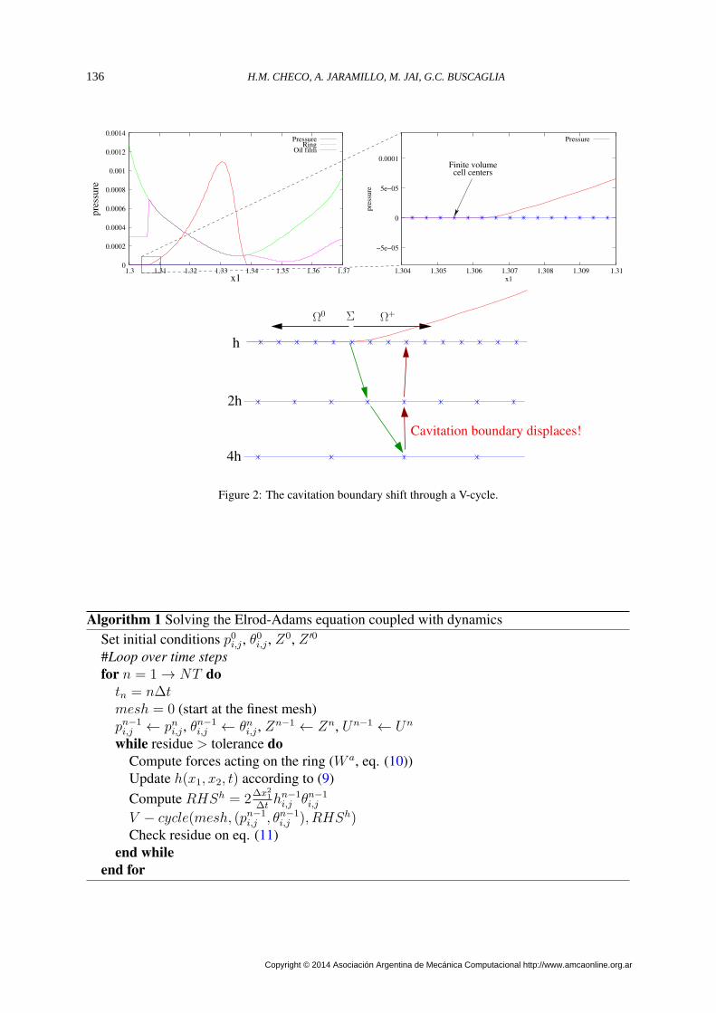
The major drawback of the multigrid method with the Elrod-Adams model is the shifting ofthe cavitation boundary done in the coarsest meshes. This situation is depicted in figure 2: aring sliding on a untextured liner generates a pressure field Ω+ (part of the domain with θ = 1)is shown in the upper left corner. A zoom showing the finite volume centers occupies the upperright corner.
The position of the cavitation boundary changes when solved in the coarser meshes (fig.2, bottom). The result is that the correction returned to the finest mesh will not resemble theproblem solved in the finest mesh. Therefore the residue of equation (11) increases at the endof a V-cycle or at least stalls.
An effective strategy to solve this problem is maintaining the cavitation boundary positioncomputed in the finest mesh. This is achieved by keeping the pressurized cells pressurized: ifafter a V-cycle the new value of pressure is null, the previous non-zero value is restored.
The definition of the mesh transfer operators IHh and IhH is also essential for a effectivemultigrid. It is to be noticed that the residueRh(qh, rh) of equation (11) is the mass imbalanceof the system. The full weighting operator Fulton et al. (1986) preserves this quantity, whichwas critical for an effective multigrid implementation.
The pseudo-code is given in algorithms 1 and 2.
Mecánica Computacional Vol XXXIII, págs. 129-145 (2014) 135
Copyright © 2014 Asociación Argentina de Mecánica Computacional http://www.amcaonline.org.ar
h
2h
4h
Cavitation boundary displaces!
cell centersFinite volume
−5e−05
0
5e−05
0.0001
1.304 1.305 1.306 1.307 1.308 1.309 1.31
pre
ssu
re
x1
Pressure
0
0.0002
0.0004
0.0006
0.0008
0.001
0.0012
0.0014
1.3 1.31 1.32 1.33 1.34 1.35 1.36 1.37
PressureRing
Oil film
pre
ssure
x1
ΣΩ0
Ω+
Figure 2: The cavitation boundary shift through a V-cycle.
Algorithm 1 Solving the Elrod-Adams equation coupled with dynamicsSet initial conditions p0i,j , θ
0i,j , Z
0, Z ′0
#Loop over time steps
for n = 1→ NT do
tn = n∆tmesh = 0 (start at the finest mesh)pn−1i,j ← pni,j , θ
n−1i,j ← θni,j , Z
n−1 ← Zn, Un−1 ← Un
while residue > tolerance do
Compute forces acting on the ring (W a, eq. (10))Update h(x1, x2, t) according to (9)
Compute RHSh = 2∆x2
1
∆thn−1i,j θn−1
i,j
V − cycle(mesh, (pn−1i,j , θn−1
i,j ), RHSh)Check residue on eq. (11)
end while
end for
H.M. CHECO, A. JARAMILLO, M. JAI, G.C. BUSCAGLIA136
Copyright © 2014 Asociación Argentina de Mecánica Computacional http://www.amcaonline.org.ar
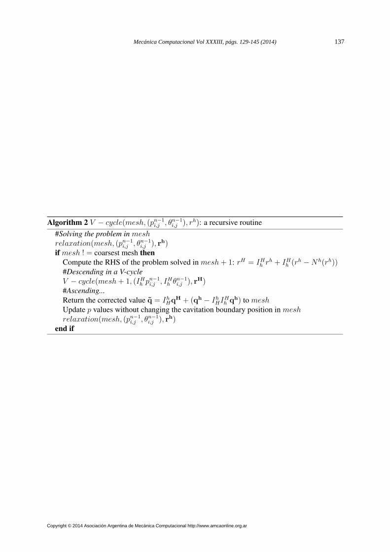
Algorithm 2 V − cycle(mesh, (pn−1i,j , θn−1
i,j ), rh): a recursive routine
#Solving the problem in meshrelaxation(mesh, (pn−1
i,j , θn−1i,j ), rh)
if mesh ! = coarsest mesh then
Compute the RHS of the problem solved in mesh+ 1: rH = IHh rh + IHh (rh −Nh(rh))#Descending in a V-cycle
V − cycle(mesh+ 1, (IHh pn−1i,j , IHh θn−1
i,j ), rH)#Ascending...
Return the corrected value q = IhHqH + (qh − IhHI
Hh qh) to mesh
Update p values without changing the cavitation boundary position in meshrelaxation(mesh, (pn−1
i,j , θn−1i,j ), rh)
end if
Mecánica Computacional Vol XXXIII, págs. 129-145 (2014) 137
Copyright © 2014 Asociación Argentina de Mecánica Computacional http://www.amcaonline.org.ar
4 NUMERICAL TESTS
The importance of the conformity degree between the matching surfaces of a lubrified pairhas been shown by Gadeschi et al. (2012) in numerical experiments involving textured rings(therefore steady state simulations) with a non mass-conserving algorithm. With this in mindthe curvature radius of the ring R is varied in the interval 4 ≤ R ≤ 1024. Typical values of R/Lfor barrel shaped compression rings are between 10 and 50. Notice that R = 1024 correspondsto a quasi conformal contact.
The assumed value of the ring mass per unit width m0 = 2 × 10⁻⁵ corresponds to a di-mensional value of 0.048 kg/m (with the chosen scales), which is realistic for the type of ringstudied here. All simulations are computed with constant piston non-dimensional velocityu = 1. This matches mid-stroke velocity (where hydrodynamic lubrication can take place) forcommon diesel engines at high revolutions per minute. Furthermore, fully flooded conditionsare addressed by setting dlub= 20.
Besides the surface texture only the load on the pad remains to be determined, which is setat its lowest value to W a
0 = 1.666× 10⁻⁴. A common non-dimensionalization in the tribologyarea is the Stribeck number:
S =µu
W a=
H2
6L2
u
W a(18)
4.1 Multigrid performance
The multigrid speedup (quotient between the runtime without and with multigrid) is proba-bly the most representative metric to measure its performance. In order to do so, we choose arepresentative texture composed of semi-ellipsoidal dimples (which will be defined in section4.2.2) with parameters l= 0.05, d=10 and period λ= 0.2 (19.6% of textured surface). The ringcurvature radius is R=64 while the load imposed on it leads to a Stribeck number of S = 10−3.
Meshes of 512 × 32, 1024 × 64 and 2048 × 128 elements lead to cell sizes of 4, 2 and1 microns. Courant number is fixed to 1, while 1000, 50 and 10 time steps are computed ineach mesh respectively. Tolerance in the residue of equation (11) is set to 10−5 of the residuein the first relaxation at each time step (computed in the Euclidian norm). Enough relaxationsweeps/V-cycles are taken to achieve this precision, with up to 20 Gauss-Seidel iterations permultigrid level.
This test was carried out in a Intel Xeon 5430 machine (8 cores of up to 2.66 Ghz, 12 Mbof cache) with 32 Gb of RAM. The coarsest mesh used in every case was of 64 × 4 elements,thus giving 4, 5 and 6 meshes used in every V-cycle.
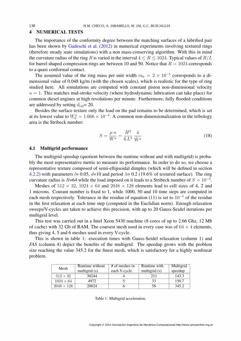
This is shown in table 1: execution times with Gauss-Seidel relaxation (column 1) andFAS (column 4) depict the benefits of the multigrid. The speedup grows with the problemsize reaching the value 345.2 for the finest mesh, which is satisfactory for a highly nonlinearproblem.
MeshRuntime withoutmultigrid (s)
# of meshes ineach V-cycle
Runtime withmultigrid (s)
Multigridspeedup
512× 32 30244 4 211 143.31024× 64 4972 5 33 150.72048× 128 20024 6 58 345.2
Table 1: Multigrid acceleration.
H.M. CHECO, A. JARAMILLO, M. JAI, G.C. BUSCAGLIA138
Copyright © 2014 Asociación Argentina de Mecánica Computacional http://www.amcaonline.org.ar
4.2 One and two-dimensional tests
The instantaneous non-dimensional clearance and friction force per unit width are given by:
C(t) = minx1,x2
h(x1, x2, t)
and
F =1
w
∫ w
0
∫ b
a
(
µu g(θ)
h+ 3h
∂p
∂x1
+ 6p∂hL
∂x1
)
dx1 dx2 (19)
where the function g(θ) is taken as
g(θ) = θ s(θ) (20)
with s(θ) the switch function
s(θ) =
1 if θ > θs0 otherwise
(21)
In this friction model θs is a threshold for the onset of friction, interpreted as the minimumlubricant fraction needed for shear forces to be transmitted from one surface to the other. In allcalculations the value θs = 0.95 has been adopted. The friction coefficient then results from
f =H
6L
F
W a(22)
where all quantities are non-dimensional.Two quantities of interest are computed from the simulations, once the transients have passed
and a periodic regime has been established. The average friction coefficient is related to powerlosses in engines
f =1λu
∫ T+λ
u
T
f(t) dt (23)
while the minimum clearance
Cmin = minT≤t≤T+λ
u
C(t) (24)
is related to surface wear. As mentioned, T is large enough so that the periodic regime hasbeen set.
4.2.1 One-dimensional textures
To study the effects of textures in the tribological performance of the lubrified pair, a sinu-soidal texture is placed on the liner:
hL(x1, x2) = d1 − cos(2 π x1/λ)
2(25)
Thus, the two parameters defining the surface are its period λ and the depth d. The ranges0 ≤ λ ≤ 2 and 0 ≤ d ≤ 10 are explored with respective increases of 0.04 and 0.2 in eachvariable, leading to 2500 simulations for each ring curvature radius R, comprising a total of5.000 transient simulations.
Mecánica Computacional Vol XXXIII, págs. 129-145 (2014) 139
Copyright © 2014 Asociación Argentina de Mecánica Computacional http://www.amcaonline.org.ar
Every simulation is checked for spatial and time convergence: meshes of at least 512 (∆x1 ≃
4 × 10⁻³) and up to 4096 elements (∆x1 ≃ 5 × 10⁻⁴) are chosen to ensure independence ofspatial discretization. A Courant number of one is enforced.
It is interesting to see the texture’s effect compared to that of an untextured liner maintainingthe rest of the parameters. For that purpose we define:
• The relative variation Vf of the average friction factor:
Vf (d, λ) =f(d, λ)− funtextured
funtextured
• The relative variation VC of the minimal clearance:
VC(d, λ) =Cmin(d, λ)− Cmin,untextured
Cmin,untextured
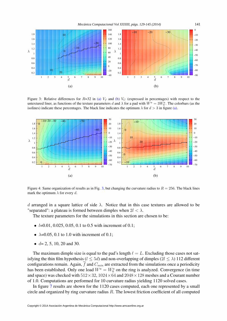
These variables are plotted in the d− λ maps (figures) 3 and 4 for m = m0.The first map depicts the situation of a ring profile with R = 32, i.e. with a moderately
pronounced convergent-divergent wedge, while the other one with a large curvature radius(R = 256) corresponds to an almost flat ring. This choice of R values is due to the fact that forthe studied range of d and λ no reduction in friction nor increase in clearance was registeredfor R ≤ 16.
Figure 3 shows the results for R = 32 and W a = 3W a0 . No increase in Cmin is seen, as all
VC values in figure 3(b) are negative. Deeper textures lead to even lower clearances. Moreover,the highest VC value is VC = 0 at d = 0 which is the untextured case.
It is interesting to see that even in this context of lower clearances, considerable reductionscan be obtained in friction, as seen in fig. 3(a).
The previously described situation for VC at R=32 changes when the sliding surfaces arenearly parallel, as with R = 256. A widespread region with high VC > 0 values has now ap-peared in figure 4(b). For every depth, a maximum in clearance is reached for λ approximatelybetween 0.75 ≤ λ ≤ 1.1. This is shown for every d by the full thick line in black crossingthe chart. Clearances are increased up to 30%. These higher clearances are accompanied bya substantial improvement in friction, as expected. The same previous texture with d = 5 andλ=1 for R = 256 returns 58% less friction than the untextured liner.
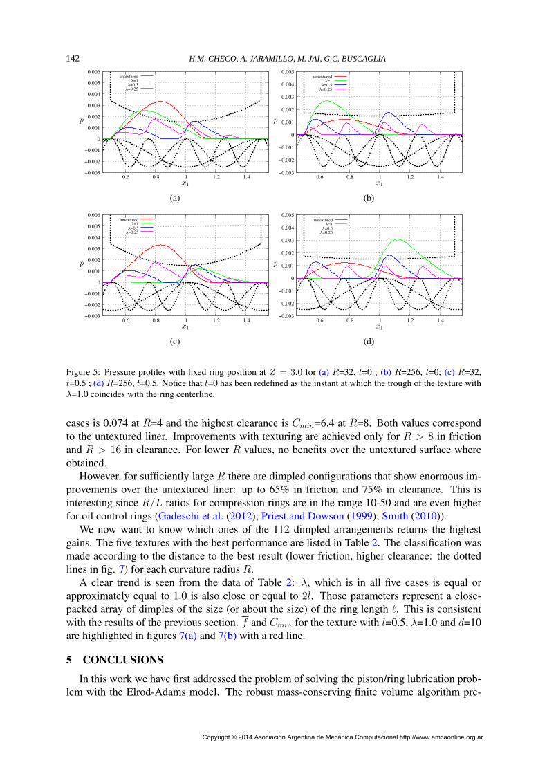
These results can be explained in terms of the load carrying capacity of textures with a sizeof about the contact length. In figure 5 the ring position has been fixed for textures with d=5and three periods: λ=1.0, 0.5 and 0.25. Two instants are shown: (i) when the trough of thetexture with λ=1.0 is centered with the ring (figures 5(a) for R=32 and 5(b) for R=256) and(ii) when the crest of the texture with λ=1.0 is centered with the ring (figures 5(c), 5(d)). Itis clear from the figure that each dimple works as a moving wedge, with a pressurized regionmoving along with it. The pressure peak, the pressurized region and therefore the load carryingcapacity grow with the dimple’s period until it is approximately of the size of the ring’s length.This effect is more pronounced for high conformity bearings, as a flat surface provides limitedload carrying capacity.
4.2.2 Two-dimensional textures
In this section we assess semi-ellipsoidal textures as portrayed in figure 6. This resemblesmore the ones produced by LST than the simplified one-dimensional textures of the preced-ing section. They are defined by a radius l (circular section in the x1-x2 plane) and a depth
H.M. CHECO, A. JARAMILLO, M. JAI, G.C. BUSCAGLIA140
Copyright © 2014 Asociación Argentina de Mecánica Computacional http://www.amcaonline.org.ar
10
0
−10
−20
2010
0.2
0.4
0.6
0.8
1
1.2
1.4
1.6
1.8
1 2 3 4 5 6 7 8 9 10−40
−20
0
20
40
60
80
100
120
140
160
d
λ
(a)
−10 −20 −30
0.2
0.4
0.6
0.8
1
1.2
1.4
1.6
1.8
1 2 3 4 5 6 7 8 9 10−90
−80
−70
−60
−50
−40
−30
−20
−10
0
d
λ
(b)
Figure 3: Relative differences for R=32 in (a) Vf and (b) VC (expressed in percentages) with respect to theuntextured liner, as functions of the texture parameters d and λ for a pad with W a
= 3W a0
. The colorbars (as theisolines) indicate these percentages. The black line indicates the optimum λ for d > 3 in figure (a).
0
−10−20 −30 −40 −50
−60
0 0.2
0.4
0.6
0.8
1
1.2
1.4
1.6
1.8
1 2 3 4 5 6 7 8 9 10−70
−60
−50
−40
−30
−20
−10
0
10
20
30
d
λ
(a)
0.2
0.4
0.6
0.8
1
1.2
1.4
1.6
1.8
1 2 3 4 5 6 7 8 9 10−70
−60
−50
−40
−30
−20
−10
0
10
20
30
0
0
10
20
−10
−10
d
λ
(b)
Figure 4: Same organization of results as in Fig. 3, but changing the curvature radius to R = 256. The black linesmark the optimum λ for every d.
d arranged in a square lattice of side λ. Notice that in this case textures are allowed to be"separated": a plateau is formed between dimples when 2l < λ.
The texture parameters for the simulations in this section are chosen to be:
• l=0.01, 0.025, 0.05, 0.1 to 0.5 with increment of 0.1;
• λ=0.05, 0.1 to 1.0 with increment of 0.1;
• d= 2, 5, 10, 20 and 30.
The maximum dimple size is equal to the pad’s length ℓ = L. Excluding those cases not sat-isfying the thin film hypothesis (l ≤ 5d) and non-overlapping of dimples (2l ≤ λ) 112 differentconfigurations remain. Again, f and Cmin are extracted from the simulations once a periodicityhas been established. Only one load W a = W a
0 on the ring is analyzed. Convergence (in timeand space) was checked with 512×32, 1024×64 and 2048×128 meshes and a Courant numberof 1.0. Computations are performed for 10 curvature radius yielding 1120 solved cases.
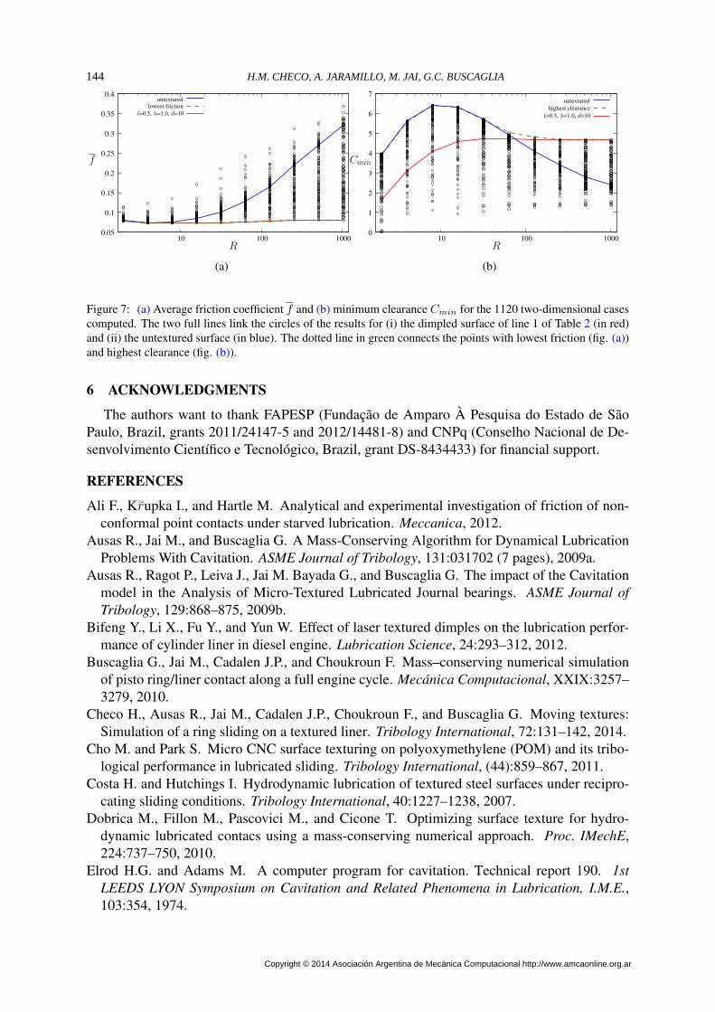
In figure 7 results are shown for the 1120 cases computed, each one represented by a smallcircle and organized by ring curvature radius R. The lowest friction coefficient of all computed
Mecánica Computacional Vol XXXIII, págs. 129-145 (2014) 141
Copyright © 2014 Asociación Argentina de Mecánica Computacional http://www.amcaonline.org.ar
−0.003
−0.002
−0.001
0
0.001
0.002
0.003
0.004
0.005
0.006
0.6 0.8 1 1.2 1.4
untexturedλ=1
λ=0.5λ=0.25
p
x1
(a)
−0.003
−0.002
−0.001
0
0.001
0.002
0.003
0.004
0.005
0.6 0.8 1 1.2 1.4
x1
λ=1untextured
λ=0.25λ=0.5
p
(b)
−0.003
−0.002
−0.001
0
0.001
0.002
0.003
0.004
0.005
0.006
0.6 0.8 1 1.2 1.4
x1
p
untexturedλ=1
λ=0.5λ=0.25
(c)
−0.003
−0.002
−0.001
0
0.001
0.002
0.003
0.004
0.005
0.6 0.8 1 1.2 1.4
x1
p
untexturedλ=1
λ=0.5λ=0.25
(d)
Figure 5: Pressure profiles with fixed ring position at Z = 3.0 for (a) R=32, t=0 ; (b) R=256, t=0; (c) R=32,t=0.5 ; (d) R=256, t=0.5. Notice that t=0 has been redefined as the instant at which the trough of the texture withλ=1.0 coincides with the ring centerline.
cases is 0.074 at R=4 and the highest clearance is Cmin=6.4 at R=8. Both values correspondto the untextured liner. Improvements with texturing are achieved only for R > 8 in frictionand R > 16 in clearance. For lower R values, no benefits over the untextured surface whereobtained.
However, for sufficiently large R there are dimpled configurations that show enormous im-provements over the untextured liner: up to 65% in friction and 75% in clearance. This isinteresting since R/L ratios for compression rings are in the range 10-50 and are even higherfor oil control rings (Gadeschi et al. (2012); Priest and Dowson (1999); Smith (2010)).
We now want to know which ones of the 112 dimpled arrangements returns the highestgains. The five textures with the best performance are listed in Table 2. The classification wasmade according to the distance to the best result (lower friction, higher clearance: the dottedlines in fig. 7) for each curvature radius R.
A clear trend is seen from the data of Table 2: λ, which is in all five cases is equal orapproximately equal to 1.0 is also close or equal to 2l. Those parameters represent a close-packed array of dimples of the size (or about the size) of the ring length ℓ. This is consistentwith the results of the previous section. f and Cmin for the texture with l=0.5, λ=1.0 and d=10are highlighted in figures 7(a) and 7(b) with a red line.
5 CONCLUSIONS
In this work we have first addressed the problem of solving the piston/ring lubrication prob-lem with the Elrod-Adams model. The robust mass-conserving finite volume algorithm pre-
H.M. CHECO, A. JARAMILLO, M. JAI, G.C. BUSCAGLIA142
Copyright © 2014 Asociación Argentina de Mecánica Computacional http://www.amcaonline.org.ar
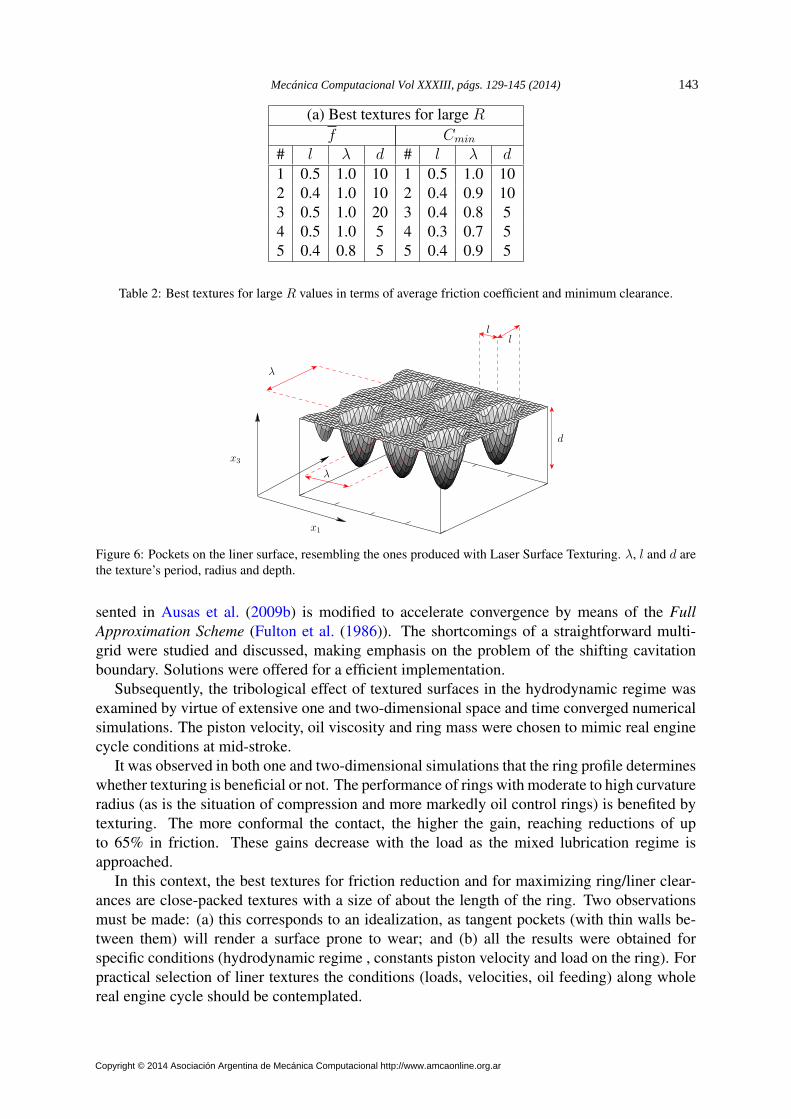
(a) Best textures for large R
f Cmin
# l λ d # l λ d1 0.5 1.0 10 1 0.5 1.0 102 0.4 1.0 10 2 0.4 0.9 103 0.5 1.0 20 3 0.4 0.8 54 0.5 1.0 5 4 0.3 0.7 55 0.4 0.8 5 5 0.4 0.9 5
Table 2: Best textures for large R values in terms of average friction coefficient and minimum clearance.
x1
x3
d
ll
λ
λ
Figure 6: Pockets on the liner surface, resembling the ones produced with Laser Surface Texturing. λ, l and d arethe texture’s period, radius and depth.
sented in Ausas et al. (2009b) is modified to accelerate convergence by means of the Full
Approximation Scheme (Fulton et al. (1986)). The shortcomings of a straightforward multi-grid were studied and discussed, making emphasis on the problem of the shifting cavitationboundary. Solutions were offered for a efficient implementation.
Subsequently, the tribological effect of textured surfaces in the hydrodynamic regime wasexamined by virtue of extensive one and two-dimensional space and time converged numericalsimulations. The piston velocity, oil viscosity and ring mass were chosen to mimic real enginecycle conditions at mid-stroke.
It was observed in both one and two-dimensional simulations that the ring profile determineswhether texturing is beneficial or not. The performance of rings with moderate to high curvatureradius (as is the situation of compression and more markedly oil control rings) is benefited bytexturing. The more conformal the contact, the higher the gain, reaching reductions of upto 65% in friction. These gains decrease with the load as the mixed lubrication regime isapproached.
In this context, the best textures for friction reduction and for maximizing ring/liner clear-ances are close-packed textures with a size of about the length of the ring. Two observationsmust be made: (a) this corresponds to an idealization, as tangent pockets (with thin walls be-tween them) will render a surface prone to wear; and (b) all the results were obtained forspecific conditions (hydrodynamic regime , constants piston velocity and load on the ring). Forpractical selection of liner textures the conditions (loads, velocities, oil feeding) along wholereal engine cycle should be contemplated.
Mecánica Computacional Vol XXXIII, págs. 129-145 (2014) 143
Copyright © 2014 Asociación Argentina de Mecánica Computacional http://www.amcaonline.org.ar
untextured
lowest friction
0.05
0.1
0.15
0.2
0.25
0.3
0.35
0.4
10 100 1000
l=0.5, λ=1.0, d=10
R
f
(a)
0
1
2
3
4
5
6
7
10 100 1000
untextured
highest clearance
R
Cmin
l=0.5, λ=1.0, d=10
(b)
Figure 7: (a) Average friction coefficient f and (b) minimum clearance Cmin for the 1120 two-dimensional casescomputed. The two full lines link the circles of the results for (i) the dimpled surface of line 1 of Table 2 (in red)and (ii) the untextured surface (in blue). The dotted line in green connects the points with lowest friction (fig. (a))and highest clearance (fig. (b)).
6 ACKNOWLEDGMENTS
The authors want to thank FAPESP (Fundação de Amparo À Pesquisa do Estado de SãoPaulo, Brazil, grants 2011/24147-5 and 2012/14481-8) and CNPq (Conselho Nacional de De-senvolvimento Científico e Tecnológico, Brazil, grant DS-8434433) for financial support.
REFERENCES
Ali F., Krupka I., and Hartle M. Analytical and experimental investigation of friction of non-conformal point contacts under starved lubrication. Meccanica, 2012.
Ausas R., Jai M., and Buscaglia G. A Mass-Conserving Algorithm for Dynamical LubricationProblems With Cavitation. ASME Journal of Tribology, 131:031702 (7 pages), 2009a.
Ausas R., Ragot P., Leiva J., Jai M. Bayada G., and Buscaglia G. The impact of the Cavitationmodel in the Analysis of Micro-Textured Lubricated Journal bearings. ASME Journal of
Tribology, 129:868–875, 2009b.Bifeng Y., Li X., Fu Y., and Yun W. Effect of laser textured dimples on the lubrication perfor-
mance of cylinder liner in diesel engine. Lubrication Science, 24:293–312, 2012.Buscaglia G., Jai M., Cadalen J.P., and Choukroun F. Mass–conserving numerical simulation
of pisto ring/liner contact along a full engine cycle. Mecánica Computacional, XXIX:3257–3279, 2010.
Checo H., Ausas R., Jai M., Cadalen J.P., Choukroun F., and Buscaglia G. Moving textures:Simulation of a ring sliding on a textured liner. Tribology International, 72:131–142, 2014.
Cho M. and Park S. Micro CNC surface texturing on polyoxymethylene (POM) and its tribo-logical performance in lubricated sliding. Tribology International, (44):859–867, 2011.
Costa H. and Hutchings I. Hydrodynamic lubrication of textured steel surfaces under recipro-cating sliding conditions. Tribology International, 40:1227–1238, 2007.
Dobrica M., Fillon M., Pascovici M., and Cicone T. Optimizing surface texture for hydro-dynamic lubricated contacs using a mass-conserving numerical approach. Proc. IMechE,224:737–750, 2010.
Elrod H.G. and Adams M. A computer program for cavitation. Technical report 190. 1st
LEEDS LYON Symposium on Cavitation and Related Phenomena in Lubrication, I.M.E.,103:354, 1974.
H.M. CHECO, A. JARAMILLO, M. JAI, G.C. BUSCAGLIA144
Copyright © 2014 Asociación Argentina de Mecánica Computacional http://www.amcaonline.org.ar
Etsion I. State of the art in laser surface texturing. J, Tribol.: Trans. ASME, 127:248–253,2005.
Etsion I. and Sher E. Improving fuel efficiency with laser surface textured piston rings. Tribol-
ogy International, 42:542–547, 2009.Fulton S.R., Ciesielsky P.E., and Schubert W.H. Multigrid methods for elliptic problems: a
review. Mon. Wea. Rev., 114:943–959, 1986.Gadeschi G.B., Backhaus K., and Knoll G. Numerical Analysis of Laser-Textured Piston-Rings
in the Hydrodynamic Lubrication Regime. Journal of Tribology, 134:041702–1–041702–8,2012.
Kovalchenko A., Ajayi O., Erdemir A., and Fenske G. Friction and wear behavior of lasertextured surface under lubricated initial point contact. Wear, 271:1719–1725, 2011.
Kovalchenko A., Ajayi O., Erdemir A., Fenske G., and Etsion I. The effect of laser surface tex-turing on transitions in lubrication regimes during unidirectional sliding contacts. Tribology
International, 38:219–225, 2005.Mishra S.P. and Polycarpou A.A. Tribological studies of unpolished laser surface textures un-
der starved lubrication conditions for use in air-conditioning and refrigeration compressors.Tribology International, 44:1890–1901, 2011.
Organisciak M. and Cavallaro G.L.A. Starved hydrodynamic lubrication of the piston ringcylinder liner contact: Preliminary study of the influence of surface texturing. Tribology and
Interface Engineering Series, 48:573–583, 2005.Pettersson U. and Jacobson S. Textured surfaces for improved lubrication at high pressure and
low sliding speed of roller/piston in hydraulic motors. Tribology International, 40:355–359,2007.
Priest M. and Dowson D.T.C.M. Predictive wear modelling of lubricated piston rings in a dieselengine. Wear, 231(1):89–101, 1999.
Qiu Y. and Khonsari M. Experimental investigation of tribological performance of laser tex-tured stainless steel rings. Tribology International, 44:635–644, 2011.
Ramesh A., Akram W., Mishra S.P., Cannon A.H., Polycarpou A.A., and King W.P. Frictioncharacteristics of microtextured surfaces under mixed and hydrodynamic lubrication. Tri-
bology International, (57):170–176, 2013.Smith E.H. Optimising the design of a piston-ring pack using DoE methods. Tribology Inter-
national, 44:29–41, 2010.Tomanik E. Friction and wear bench test of different engine liner surface finishes. Tribology
International, 41:1032–1038, 2008.Tomanik E. Modelling the hydrodynamic support of cylinder bore and piston rings with laser
textured surfaces. Tribology International, 59:90–96, 2013.Wang X., Adachi K., Otsuka K., and Kato K. Optimization of the surface texture for silicon
carbide sliding in water. Applied Surface Science, 253:1282–1286, 2006.Yuan S., Huang W., and Wang X. Orientation effects of micro-grooves on sliding surfaces.
Tribology International, 44:1047–1054, 2011.Zhang J. and Meng Y. Direct observation of cavitation phenomenon and hydrodynamic lubri-
cation analysis of textured surfaces. Tribology Letters, 46:147–158, 2012.
Mecánica Computacional Vol XXXIII, págs. 129-145 (2014) 145
Copyright © 2014 Asociación Argentina de Mecánica Computacional http://www.amcaonline.org.ar


![Analysis of the coated and textured ring/liner conjunction ...the film thickness of the textured liner can be described as [1, 16]: 22 L0 p p(),4/0.5cos(π/)1 (()) hxt h x b h x r](https://img.pdfslide.net/doc/110x75/601fefb092b88d093049cc94/analysis-of-the-coated-and-textured-ringliner-conjunction-the-film-thickness.jpg)