Embed Size (px)
Citation preview
Trimble’s RoadLink Utility TutorialsTrimble’s RoadLink™ utility is an interface between third-party road definitions and Trimble survey devices. It lets you import or key in road definitions, view them graphically, edit them if required, and then export them to a Trimble survey device (controller) for stakeout.
Get started with RoadLink by working through the following tutorials:
• Tutorial 1: Import third-party design files defining the horizontal and vertical alignments and cross-sections. The road definition is viewed graphically and a file is sent to the controller for stakeout. (15 minutes)
• Tutorial 2: Manually enter an alignment from construction drawings. Earthworks volumes are calculated and a file is sent to the controller for stakeout. (30 minutes)
For more information about RoadLink, refer to the Trimble Geomatics Office™ User Guide or the Help. As you work, press [F1] or click the Help button for detailed information about the dialog you are in.
Trimble’s RoadLink Utility Tutorials
Tutorial 1: Importing a Road DefinitionThis tutorial shows how to import third-party files that define a road. You will do the following:
1. Set up a project.
2. Start RoadLink.
3. Import a road definition.
4. View the horizontal and vertical alignments.
5. View the cross-sections.
6. Add the Plan view linework.
7. Transfer the road for stakeout (export the design).
Setting up a Project
To set up a new project:
1. Start the Trimble Geomatics Office software.
2. Do one of the following:
– Select File / New Project.
– On the Standard toolbar, click the New Project tool .
3. In the Name field, enter a project name.
Page 2 of 26
Trimble’s RoadLink Utility Tutorials
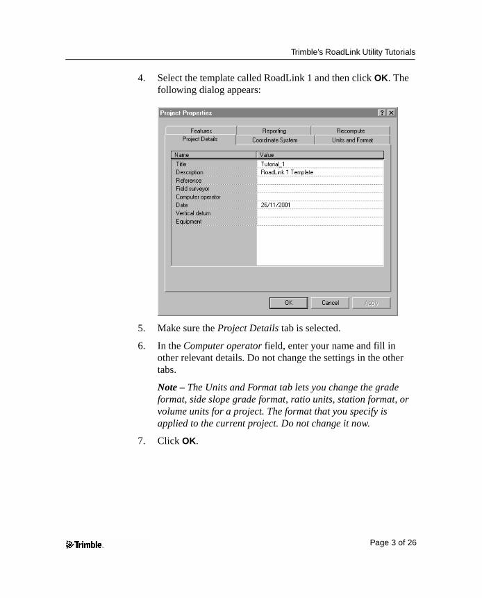
4. Select the template called RoadLink 1 and then click OK. The following dialog appears:
5. Make sure the Project Details tab is selected.
6. In the Computer operator field, enter your name and fill in other relevant details. Do not change the settings in the other tabs.
Note – The Units and Format tab lets you change the grade format, side slope grade format, ratio units, station format, or volume units for a project. The format that you specify is applied to the current project. Do not change it now.
7. Click OK.
Page 3 of 26
Trimble’s RoadLink Utility Tutorials
Starting the RoadLink Utility
To start RoadLink:
• In the Plan view, select Tools / RoadLink / Start.
The RoadLink window appears.
Importing a Road Definition
A wizard guides you through the process of importing a road definition. To import the road definition:
1. Select File / Import. The Import dialog appears.
2. Select the Road tab.
3. From the Types list, select Third-party road definition file and click OK. The File Open wizard appears.
4. From the Data format list, select Autodesk Civil Design / Softdesk and click Next.
5. Select the following files from C:\ Trimble Geomatics Office \ Projects \ your project name \ Checkin \:
– Autodesk Road Horiz
– Autodesk Road Vert
– Autodesk Road Xsec
These files contain the horizontal and vertical alignment definitions and the cross-section data for a road designed using Autodesk Civil Design software.
6. Click Next.
7. Select the Center alignment and click Next.
8. Select the Datum #1 surface and click Next.
Page 4 of 26
Trimble’s RoadLink Utility Tutorials
9. Select the following check boxes:
– Left of road
– Right of road
– Exclude main alignment from template
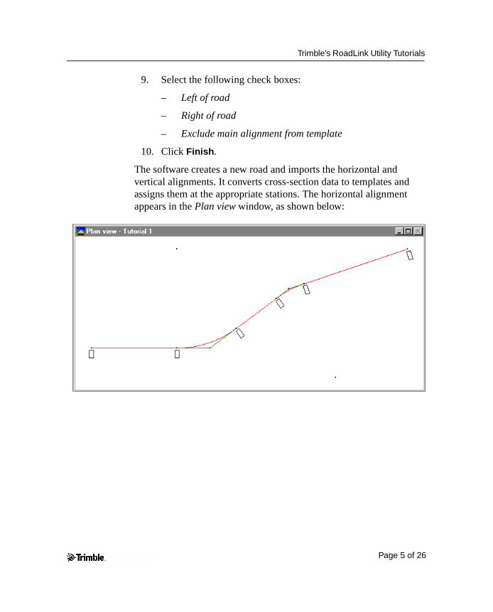
10. Click Finish.
The software creates a new road and imports the horizontal and vertical alignments. It converts cross-section data to templates and assigns them at the appropriate stations. The horizontal alignment appears in the Plan view window, as shown below:
Page 5 of 26
Trimble’s RoadLink Utility Tutorials
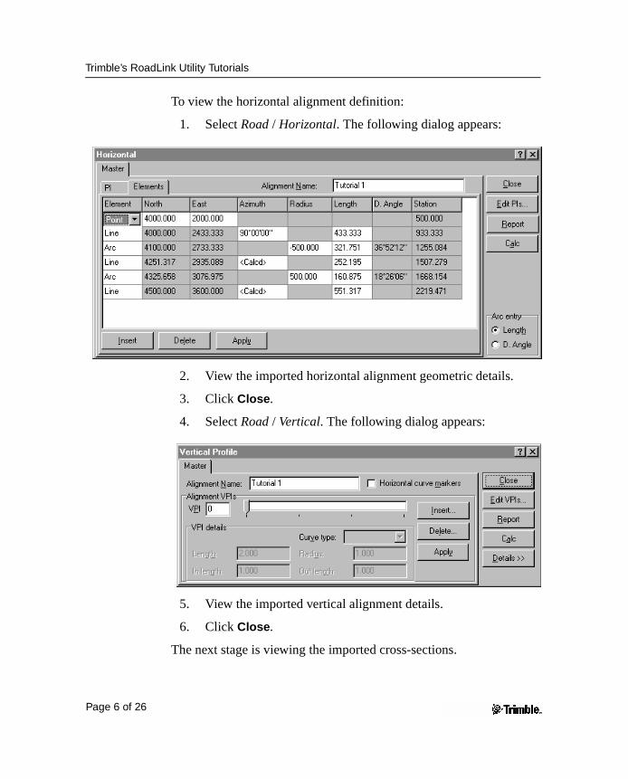
To view the horizontal alignment definition:
1. Select Road / Horizontal. The following dialog appears:
2. View the imported horizontal alignment geometric details.
3. Click Close.
4. Select Road / Vertical. The following dialog appears:
5. View the imported vertical alignment details.
6. Click Close.
The next stage is viewing the imported cross-sections.
Page 6 of 26
Trimble’s RoadLink Utility Tutorials
Viewing the Imported Cross-Sections
You can view the imported cross-sections. To do this:
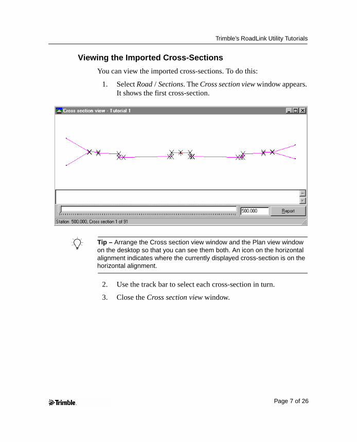
1. Select Road / Sections. The Cross section view window appears. It shows the first cross-section.
B Tip – Arrange the Cross section view window and the Plan view window on the desktop so that you can see them both. An icon on the horizontal alignment indicates where the currently displayed cross-section is on the horizontal alignment.
2. Use the track bar to select each cross-section in turn.
3. Close the Cross section view window.
Page 7 of 26
Trimble’s RoadLink Utility Tutorials
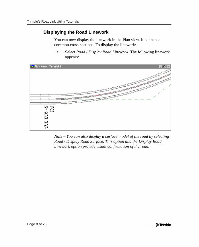
Displaying the Road Linework
You can now display the linework in the Plan view. It connects common cross-sections. To display the linework:
• Select Road / Display Road Linework. The following linework appears:
Note – You can also display a surface model of the road by selecting Road / Display Road Surface. This option and the Display Road Linework option provide visual confirmation of the road.
Page 8 of 26
Trimble’s RoadLink Utility Tutorials
Transferring the Road
You can now transfer the road alignment to a Trimble controller ready for stakeout. You can transfer:
• the horizontal and vertical alignments
• the templates
To export the road:
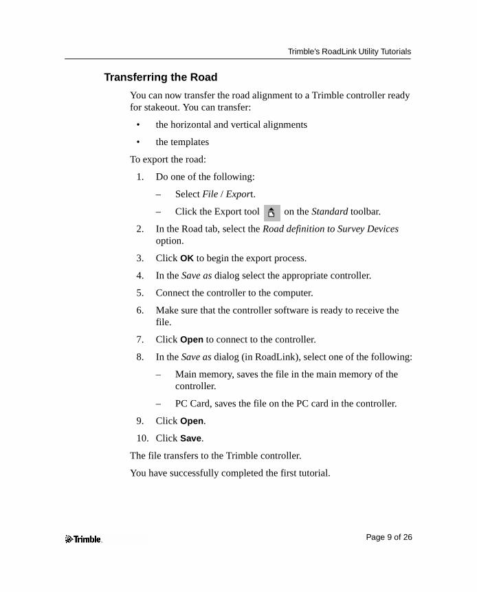
1. Do one of the following:
– Select File / Export.
– Click the Export tool on the Standard toolbar.
2. In the Road tab, select the Road definition to Survey Devices option.
3. Click OK to begin the export process.
4. In the Save as dialog select the appropriate controller.
5. Connect the controller to the computer.
6. Make sure that the controller software is ready to receive the file.
7. Click Open to connect to the controller.
8. In the Save as dialog (in RoadLink), select one of the following:
– Main memory, saves the file in the main memory of the controller.
– PC Card, saves the file on the PC card in the controller.
9. Click Open.
10. Click Save.
The file transfers to the Trimble controller.
You have successfully completed the first tutorial.
Page 9 of 26
Trimble’s RoadLink Utility Tutorials
Tutorial 2: Manually Entering a Road DefinitionThis tutorial shows how to input a road definition manually. You will do the following:
1. Set up a project.
2. Form a surface model using the DTMLink™ utility.
3. Start RoadLink.
4. Create a template.
5. Input the horizontal alignment.
6. Input the vertical alignment.
7. Apply templates.
8. Apply superelevation.
9. Calculate the volumes.
10. Export the design (transfer the road for stakeout).
Setting up a Project
To set up a new project:
1. Start Trimble Geomatics Office.
2. Do one of the following:
– Select File / New Project.
– Click the New Project tool on the Standard toolbar.
3. In the Name field, enter a project name.
4. Click the template called RoadLink 2.
Page 10 of 26
Trimble’s RoadLink Utility Tutorials
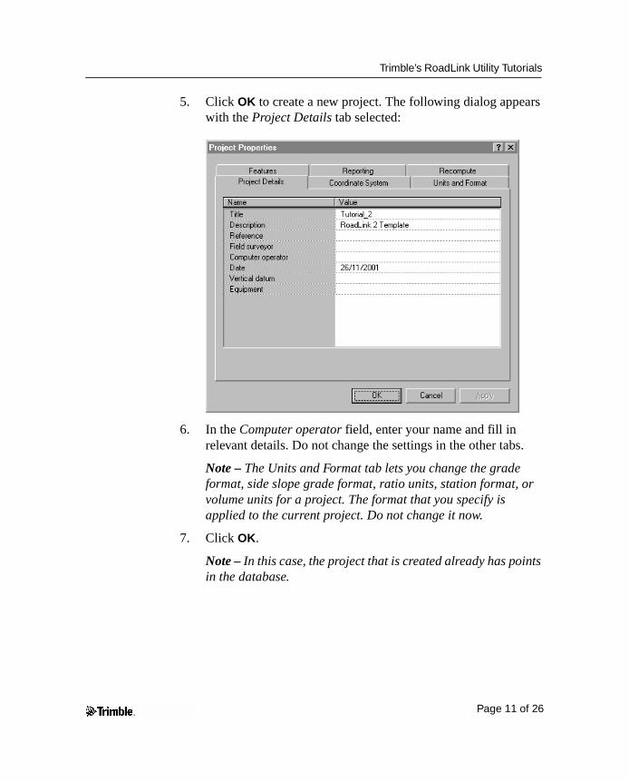
5. Click OK to create a new project. The following dialog appears with the Project Details tab selected:
6. In the Computer operator field, enter your name and fill in relevant details. Do not change the settings in the other tabs.
Note – The Units and Format tab lets you change the grade format, side slope grade format, ratio units, station format, or volume units for a project. The format that you specify is applied to the current project. Do not change it now.
7. Click OK.
Note – In this case, the project that is created already has points in the database.
Page 11 of 26
Trimble’s RoadLink Utility Tutorials
Creating a Surface Model
A surface model lets you compute earthworks volumes.
In this part of the tutorial, you create a surface model using DTMLink, and select this as the surface in the RoadLink project.
To create a surface model:
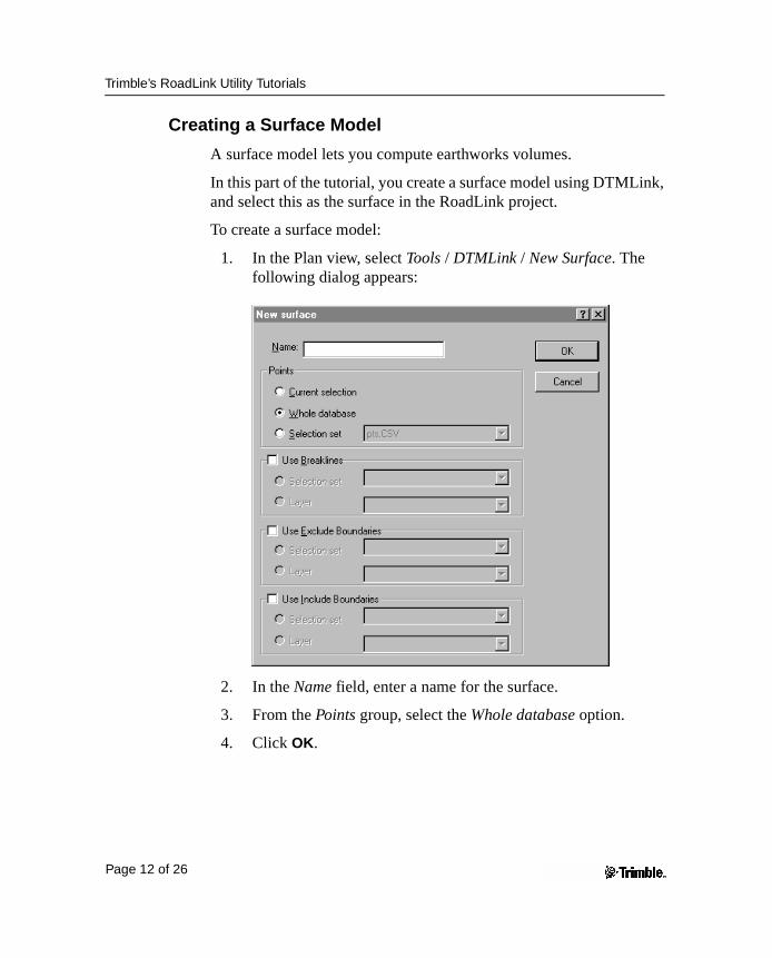
1. In the Plan view, select Tools / DTMLink / New Surface. The following dialog appears:
2. In the Name field, enter a name for the surface.
3. From the Points group, select the Whole database option.
4. Click OK.
Page 12 of 26
Trimble’s RoadLink Utility Tutorials
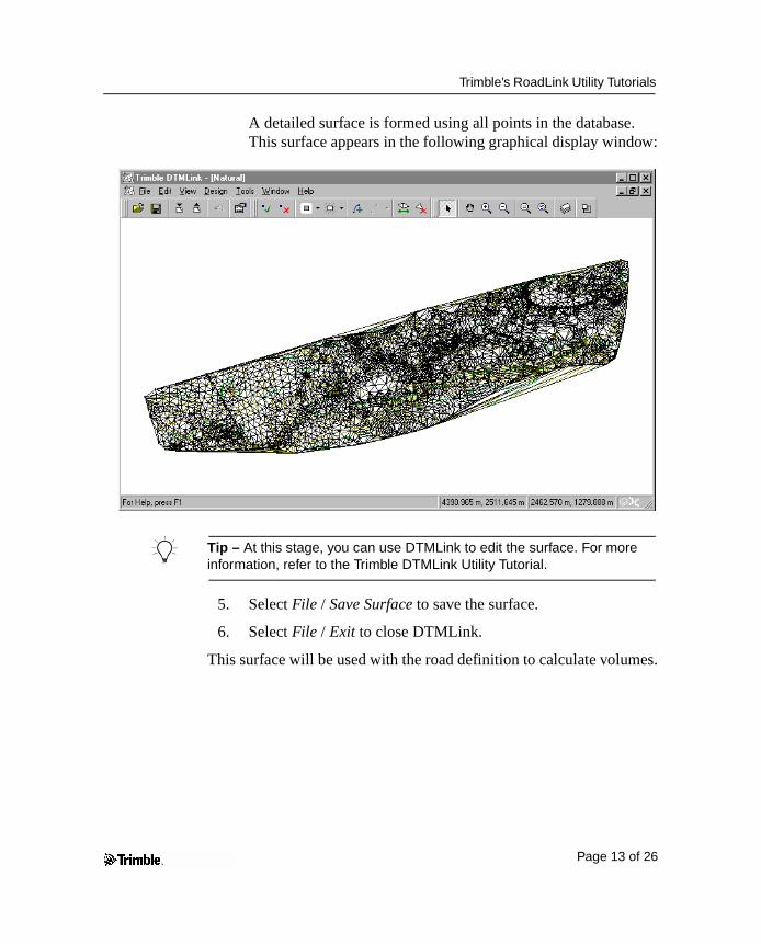
A detailed surface is formed using all points in the database. This surface appears in the following graphical display window:
B Tip – At this stage, you can use DTMLink to edit the surface. For more information, refer to the Trimble DTMLink Utility Tutorial.
5. Select File / Save Surface to save the surface.
6. Select File / Exit to close DTMLink.
This surface will be used with the road definition to calculate volumes.
Page 13 of 26
Trimble’s RoadLink Utility Tutorials
Starting the RoadLink Utility
Start RoadLink now:
• In the Plan view, select Tools / RoadLink / Start.
The Plan View window appears.
Creating a Template
A template represents the design cross-section for the road definition. In this second tutorial, you create a new template.
To create a template:
1. Select Utilities / Template Editor. The Edit Template dialog appears.
2. Select Library / New. The Create New Template Library dialog appears.
3. Enter Tutorial_2 as the name for the new library.
4. Click OK.
5. Select Template / New.
6. Enter Section3 as the name for the new template.
7. Click OK.
The template name appears. The default design surface (Subgrade) and the first element in the template (Subgrade01) are added. They appear as a tree structure.
Note – All templates begin with the element Subgrade01 which has default Delta elevation and Offset values of 0.000. This element is automatically created when you define a new template.
Page 14 of 26
Trimble’s RoadLink Utility Tutorials
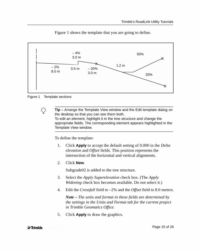
Figure 1 shows the template that you are going to define.
Figure 1 Template sections
B Tip – Arrange the Template View window and the Edit template dialog on the desktop so that you can see them both. To edit an element, highlight it in the tree structure and change the appropriate fields. The corresponding element appears highlighted in the Template View window.
To define the template:
1. Click Apply to accept the default setting of 0.000 in the Delta elevation and Offset fields. This position represents the intersection of the horizontal and vertical alignments.
2. Click New.
Subgrade02 is added to the tree structure.
3. Select the Apply Superelevation check box. (The Apply Widening check box becomes available. Do not select it.)
4. Edit the Crossfall field to –2% and the Offset field to 8.0 meters.
Note – The units and format in these fields are determined by the settings in the Units and Format tab for the current project in Trimble Geomatics Office.
5. Click Apply to draw the graphics.
XX
X
– 2%8.0 m
– 4%3.0 m
0.5 m – 20%3.0 m
1.2 m
50%
20%
Page 15 of 26
Trimble’s RoadLink Utility Tutorials
Note – You have entered the first two element types from Table 1.1.
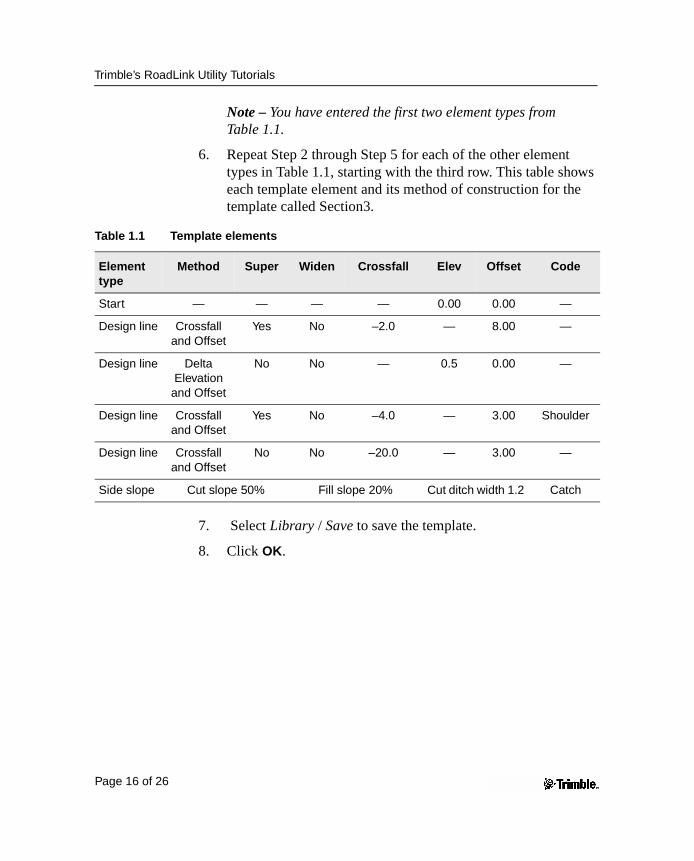
6. Repeat Step 2 through Step 5 for each of the other element types in Table 1.1, starting with the third row. This table shows each template element and its method of construction for the template called Section3.
7. Select Library / Save to save the template.
8. Click OK.
Table 1.1 Template elements
Element type
Method Super Widen Crossfall Elev Offset Code
Start — — — — 0.00 0.00 —
Design line Crossfall and Offset
Yes No –2.0 — 8.00 —
Design line Delta Elevation
and Offset
No No — 0.5 0.00 —
Design line Crossfall and Offset
Yes No –4.0 — 3.00 Shoulder
Design line Crossfall and Offset
No No –20.0 — 3.00 —
Side slope Cut slope 50% Fill slope 20% Cut ditch width 1.2 Catch
Page 16 of 26
Trimble’s RoadLink Utility Tutorials
Applying the Horizontal Alignment
To apply a horizontal alignment to the new road:
1. Select File / New Road.
2. In the Road name field, enter Demo.
3. Set the Start Station field to 500.
4. From the Surface list, select the surface that you created using the DTMLink.
Note – Select View / Surface to view this surface. This is optional.
5. Click OK. The Horizontal dialog appears.
6. Select the PI tab.
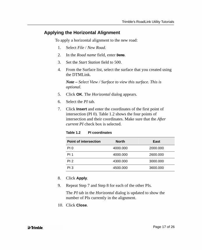
7. Click Insert and enter the coordinates of the first point of intersection (PI 0). Table 1.2 shows the four points of intersection and their coordinates. Make sure that the After current PI check box is selected.
8. Click Apply.
9. Repeat Step 7 and Step 8 for each of the other PIs.
The PI tab in the Horizontal dialog is updated to show the number of PIs currently in the alignment.
10. Click Close.
Table 1.2 PI coordinates
Point of intersection North East
PI 0 4000.000 2000.000
PI 1 4000.000 2600.000
PI 2 4300.000 3000.000
PI 3 4500.000 3600.000
Page 17 of 26
Trimble’s RoadLink Utility Tutorials
B Tip – To view the graphics, select View / Zoom Extents. To confirm the entries, click Edit PIs. Then click Close again.
To apply the curve details to each of the points of intersection:
1. Use the track bar to select PI 1.
2. In the Curve type field, select Circular.
3. Set the Radius field to 500.000.
4. Click Apply (or select PI 2) to accept the defaults in the other fields.
To apply the curve details for PI 2:
1. In the Curve type field, select Circular.
2. Set the Radius field to 500.000.
3. Click Apply.
The relevant fields are updated. For example, at PI 2 the arc length is calculated.
B Tip – To generate a report of the horizontal alignment, click Report.
4. Click Close.
Page 18 of 26
Trimble’s RoadLink Utility Tutorials
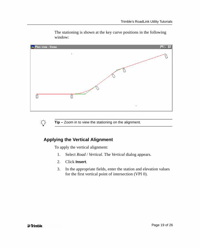
The stationing is shown at the key curve positions in the following window:
B Tip – Zoom in to view the stationing on the alignment.
Applying the Vertical Alignment
To apply the vertical alignment:
1. Select Road / Vertical. The Vertical dialog appears.
2. Click Insert.
3. In the appropriate fields, enter the station and elevation values for the first vertical point of intersection (VPI 0).
Page 19 of 26
Trimble’s RoadLink Utility Tutorials
Table 1.3 shows the values for each of the four vertical points of intersection.
4. Click Apply.
5. Repeat Step 2 and Step 3 for each of the other VPIs in Table 1.3. Make sure that the After current VPI check box is selected.
6. Click Close.
B Tip – To check that these entries are correct, click Edit VPIs. Then click Close again.
To apply the curve details to each of the vertical points of intersection:
1. Use the track bar to select VPI 1.
B Tip – If you enter 1 in the VPI field and press [Tab] to update the entry, the track bar moves to VPI 1.
2. In the Curve type field, select Sym Parabola from the list.
3. Set the Length field to 500.000.
4. Click Apply (or select VPI 2) to accept the defaults in the other fields.
5. Repeat Step 1 through Step 4 for VPI 2. Use the same settings.
6. Click Close.
Table 1.3 VPI values
Station Elevation
VPI 0 500.000 46.000
VPI 1 900.000 28.000
VPI 2 1 + 600.000 24.000
VPI 3 2 + 219.470 17.000
Page 20 of 26
Trimble’s RoadLink Utility Tutorials
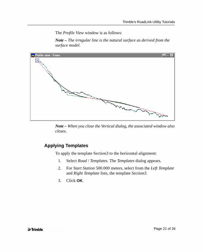
The Profile View window is as follows:
Note – The irregular line is the natural surface as derived from the surface model.
Note – When you close the Vertical dialog, the associated window also closes.
Applying Templates
To apply the template Section3 to the horizontal alignment:
1. Select Road / Templates. The Templates dialog appears.
2. For Start Station 500.000 meters, select from the Left Template and Right Template lists, the template Section3.
3. Click OK.
Page 21 of 26
Trimble’s RoadLink Utility Tutorials
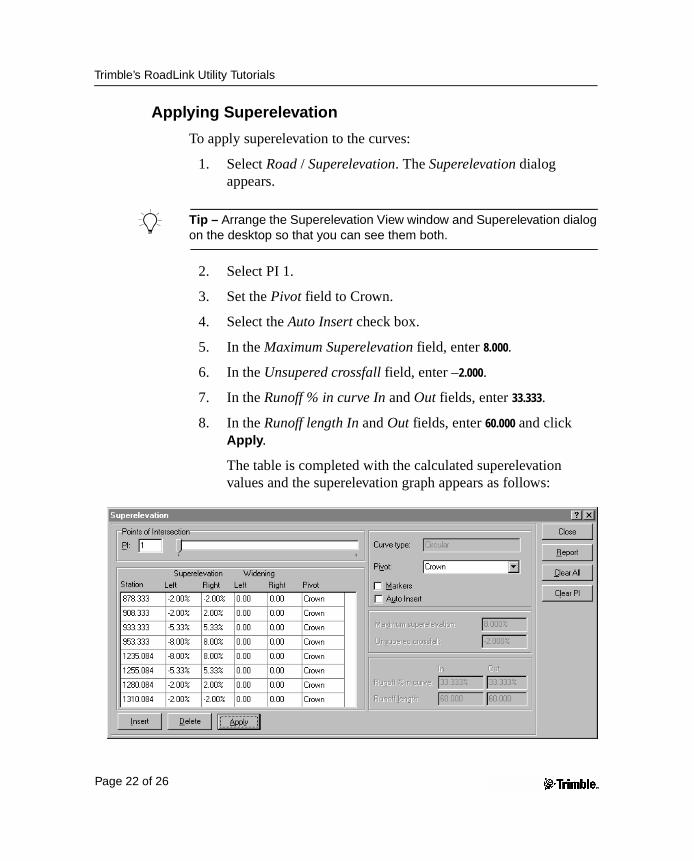
Applying Superelevation
To apply superelevation to the curves:
1. Select Road / Superelevation. The Superelevation dialog appears.
B Tip – Arrange the Superelevation View window and Superelevation dialog on the desktop so that you can see them both.
2. Select PI 1.
3. Set the Pivot field to Crown.
4. Select the Auto Insert check box.
5. In the Maximum Superelevation field, enter 8.000.
6. In the Unsupered crossfall field, enter –2.000.
7. In the Runoff % in curve In and Out fields, enter 33.333.
8. In the Runoff length In and Out fields, enter 60.000 and click Apply.
The table is completed with the calculated superelevation values and the superelevation graph appears as follows:
Page 22 of 26
Trimble’s RoadLink Utility Tutorials
9. Select PI 2.
10. Select the Auto Insert check box.
11. Accept the Maximum Superelevation and Unsupered crossfall default values.
12. In the Runoff % in curve In and Out fields, enter 33.333.
13. In the Runoff length In and Out fields, enter 60.000.
14. Click Apply.
B Tip – To see the super graph for both curves, in the Superelevation view window, right-click to access the shortcut menu and then select Zoom extents.
15. Click Close.
Calculating the Volumes
Use the automatic report generation feature of RoadLink to create an earthworks Volume report.
To create and view an earthworks Volume report:
1. Select Road / Reports / Volumes.
2. The Volume Report dialog appears.
3. Click OK to accept the default Start and End station values.
The report appears.
4. View the report, then close.
Page 23 of 26
Trimble’s RoadLink Utility Tutorials
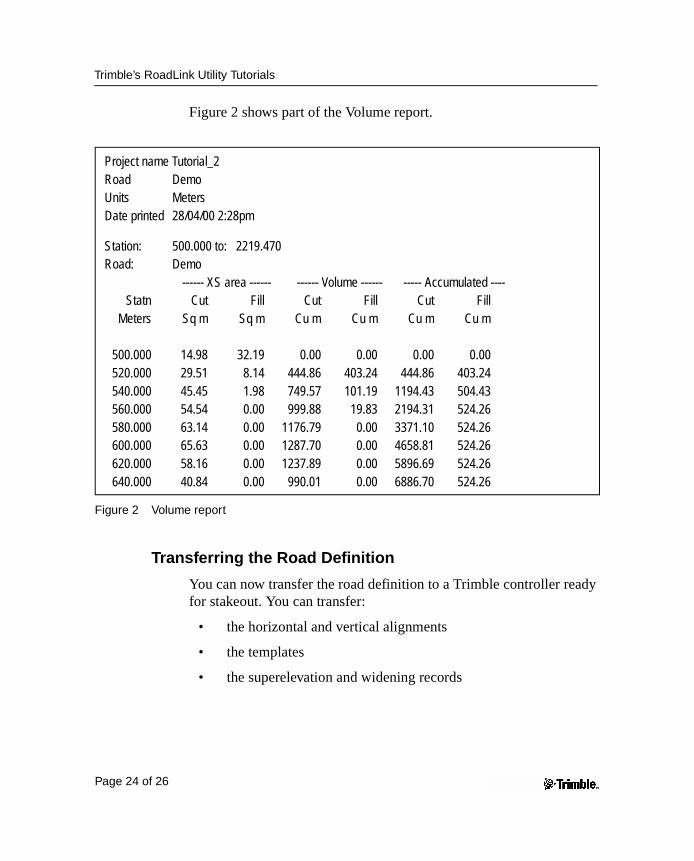
Figure 2 shows part of the Volume report.
Figure 2 Volume report
Transferring the Road Definition
You can now transfer the road definition to a Trimble controller ready for stakeout. You can transfer:
• the horizontal and vertical alignments
• the templates
• the superelevation and widening records
Project name Tutorial_2Road DemoUnits MetersDate printed 28/04/00 2:28pm
Station: 500.000 to: 2219.470Road: Demo
------ XS area ------ ------ Volume ------ ----- Accumulated ----Statn Cut Fill Cut Fill Cut Fill
Meters Sq m Sq m Cu m Cu m Cu m Cu m
500.000 14.98 32.19 0.00 0.00 0.00 0.00520.000 29.51 8.14 444.86 403.24 444.86 403.24540.000 45.45 1.98 749.57 101.19 1194.43 504.43560.000 54.54 0.00 999.88 19.83 2194.31 524.26580.000 63.14 0.00 1176.79 0.00 3371.10 524.26600.000 65.63 0.00 1287.70 0.00 4658.81 524.26620.000 58.16 0.00 1237.89 0.00 5896.69 524.26640.000 40.84 0.00 990.01 0.00 6886.70 524.26
Page 24 of 26
Trimble’s RoadLink Utility Tutorials
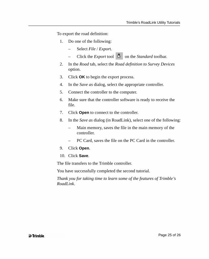
To export the road definition:
1. Do one of the following:
– Select File / Export.
– Click the Export tool on the Standard toolbar.
2. In the Road tab, select the Road definition to Survey Devices option.
3. Click OK to begin the export process.
4. In the Save as dialog, select the appropriate controller.
5. Connect the controller to the computer.
6. Make sure that the controller software is ready to receive the file.
7. Click Open to connect to the controller.
8. In the Save as dialog (in RoadLink), select one of the following:
– Main memory, saves the file in the main memory of the controller.
– PC Card, saves the file on the PC Card in the controller.
9. Click Open.
10. Click Save.
The file transfers to the Trimble controller.
You have successfully completed the second tutorial.
Thank you for taking time to learn some of the features of Trimble’s RoadLink.
Page 25 of 26

Trimble’s RoadLink Utility Tutorials
Copyright and Trademarks
© 2000–2002 Trimble Navigation Limited. All rights reserved. The Globe & Triangle logo, Trimble, DTMLink, RoadLink, and Trimble Geomatics Office are trademarks of Trimble Navigation Limited. All other trademarks are the property of their respective owners.
Page 26 of 26