Embed Size (px)
Citation preview
2131 Sunnydale Blvd, Clearwater, FL 33765 · (727)461-1888 · Fax (727)461-1858
[email protected] · www.triontech.com
TRION TECHNOLOGY
APOLLO
OPERATOR & MAINTENANCE MANUAL
Version 2.0 (25-May-2010)
2
TABLE OF CONTENTS
WARRANTY -------------------------------------------------------------------------------------------- 4 SERVICE INFORMATION -------------------------------------------------------------------------------------------- 5 SYSTEM WARNING -------------------------------------------------------------------------------------------- 6 SYSTEM DESCRIPTION -------------------------------------------------------------------------------------------- 7
GENERAL DESCRIPTION -------------------------------------------------------------------------------------------- 7 EQUIPMENT -------------------------------------------------------------------------------------------- 8
EMERGENCY SHUTOFF -------------------------------------------------------------------------------------------- 8 PROCESS CHAMBER -------------------------------------------------------------------------------------------- 9 RF GENERATOR -------------------------------------------------------------------------------------------- 9 AUTOMATIC RF TUNING -------------------------------------------------------------------------------------------- 10 MANUAL RF TUNING -------------------------------------------------------------------------------------------- 11 PROCESS CONTROLLER -------------------------------------------------------------------------------------------- 12 VACUUM SYSTEM -------------------------------------------------------------------------------------------- 13 ROBOTIC WAFER HANDLER -------------------------------------------------------------------------------------------- 14 RECIRCULATING CHILLER -------------------------------------------------------------------------------------------- 14
SAFETY SPECIFICATIONS -------------------------------------------------------------------------------------------- 15
SAFETY STANDARDS -------------------------------------------------------------------------------------------- 15 LOCK OUT/TAG OUT -------------------------------------------------------------------------------------------- 15 EMERGENCY OFF SYSTEM -------------------------------------------------------------------------------------------- 16 INTERLOCKS -------------------------------------------------------------------------------------------- 16 EQUIPMENT ELECTRICAL DESIGN -------------------------------------------------------------------------------------------- 17 CHEMICAL USE -------------------------------------------------------------------------------------------- 17 EMISSIONS -------------------------------------------------------------------------------------------- 17 LABELING -------------------------------------------------------------------------------------------- 18 EARTHQUAKE PROTECTION -------------------------------------------------------------------------------------------- 18 MECHANICAL SAFETY -------------------------------------------------------------------------------------------- 18 “WHAT IF” HAZARD ANALYSIS -------------------------------------------------------------------------------------------- 19
INSTALLATION -------------------------------------------------------------------------------------------- 20
INSPECTION -------------------------------------------------------------------------------------------- 20 FACILITIES -------------------------------------------------------------------------------------------- 20 INSTALLATION PROCEDURE -------------------------------------------------------------------------------------------- 20
RF WARNING -------------------------------------------------------------------------------------------- 22 PROCESS CONTROLLER OPERATION
-------------------------------------------------------------------------------------------- 23
TYPICAL PROCESS CONDITIONS -------------------------------------------------------------------------------------------- 35 SYSTEM CLEANING -------------------------------------------------------------------------------------------- 37 SYSTEM MAINTENANCE -------------------------------------------------------------------------------------------- 38 PERIODIC MAINT. SCHEDULE -------------------------------------------------------------------------------------------- 42 APPENDIX A - FACILITIES -------------------------------------------------------------------------------------------- 43

3
© 2006 Trion Technology, Inc. All rights reserved. This manual may not be copied, in full or in part, without the express written approval of the copyright holder.
4
WARRANTY
The TRION system is guaranteed to be free of defects in workmanship and components. This warranty covers labor and parts for a period of one year, unless an extended warranty has been purchased. The exclusive remedy for any breach or violation of the warranty is as follows: TRION TECHNOLOGY F.O.B CLEARWATER, FLORIDA will furnish without charge repairs to or replacement of the parts or equipment which proved defective in material or workmanship. No claim may be made for any incidental or consequential damages. All transportation and shipping charges must be prepaid by the customer. TRION TECHNOLOGY will inspect the equipment and decide upon such repairs or replacement as necessary. The customer will be notified of any charges incurred that are not covered by this warranty prior to accomplishment of any such repairs. Any customer modification of this equipment, or any repairs, undertaken without the prior consent of TRION TECHNOLOGY will render this warranty void. This warranty is expressly in lieu of all other warranties, express or implied, including any implied warranty of merchantability or fitness for a particular purpose unless otherwise agreed in writing signed by TRION TECHNOLOGY.
5
SERVICE INFORMATION
NOTIFICATION OF EQUIPMENT PROBLEMS: If the system has a failure or other equipment problems you must notify TRION TECHNOLOGY immediately in writing by either FAX to (727) 447-1581 or e-mail at [email protected], addressed to the Service Coordinator. In addition please call the Service Department at (727) 447-1110 to schedule a service trip. Phone help is always provided free of charge. However, if the system is out of warranty a purchase order number will be required before a service trip is scheduled. RETURN OF EQUIPMENT: If an instrument is to be returned to TRION for service or for any reason, the following procedure should be followed: Call the TRION TECHNOLOGY Service Department at (727) 447-1110 for a return authorization number (RMA). You may also e-mail TRION at “[email protected]” with any service related questions. If the unit is received without this number on the outside of the box it will be rejected by the Service Department. Repack the instrument in the original shipping container. If this is no longer available, take special precautions to avoid damage to any fragile components. TRION will not be responsible for any damages incurred during shipment from customer to TRION. A shipping container may be purchased from TRION TECHNOLOGY for a nominal charge. If the instrument is still under warranty, the only charges will be shipping costs. If the instrument is out of warranty, a purchase order will be required and you will be billed for all parts and service. If you have any questions, do not hesitate to contact TRION Customer Service Department.
6
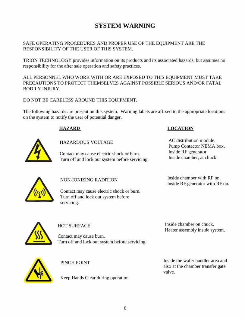
SYSTEM WARNING SAFE OPERATING PROCEDURES AND PROPER USE OF THE EQUIPMENT ARE THE RESPONSIBILITY OF THE USER OF THIS SYSTEM. TRION TECHNOLOGY provides information on its products and its associated hazards, but assumes no responsibility for the after sale operation and safety practices. ALL PERSONNEL WHO WORK WITH OR ARE EXPOSED TO THIS EQUIPMENT MUST TAKE PRECAUTIONS TO PROTECT THEMSELVES AGAINST POSSIBLE SERIOUS AND/OR FATAL BODILY INJURY. DO NOT BE CARELESS AROUND THIS EQUIPMENT. The following hazards are present on this system. Warning labels are affixed to the appropriate locations on the system to notify the user of potential danger. HAZARD LOCATION
HAZARDOUS VOLTAGE Contact may cause electric shock or burn. Turn off and lock out system before servicing.
AC distribution module. Pump Contactor NEMA box. Inside RF generator. Inside chamber, at chuck.
NON-IONIZING RADITION Contact may cause electric shock or burn. Turn off and lock out system before servicing.
Inside chamber with RF on. Inside RF generator with RF on.
HOT SURFACE Contact may cause burn. Turn off and lock out system before servicing.
Inside chamber on chuck. Heater assembly inside system.
PINCH POINT Keep Hands Clear during operation.
Inside the wafer handler area and also at the chamber transfer gate valve.
7
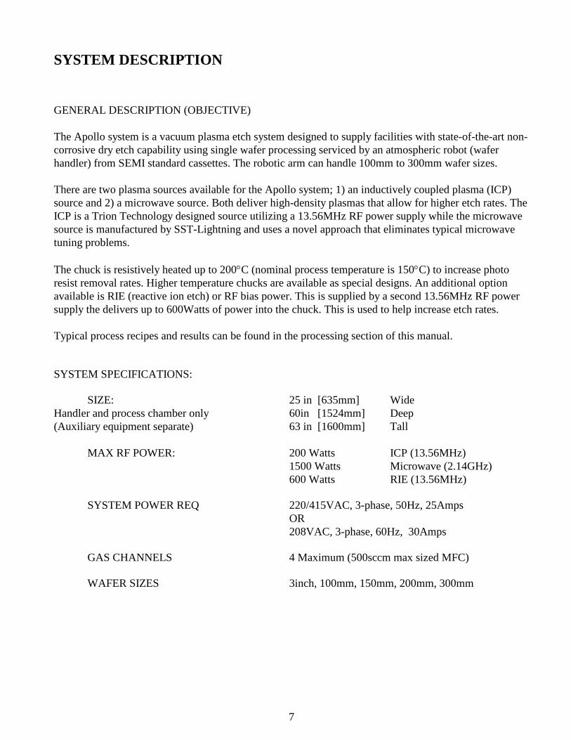
SYSTEM DESCRIPTION GENERAL DESCRIPTION (OBJECTIVE) The Apollo system is a vacuum plasma etch system designed to supply facilities with state-of-the-art non-corrosive dry etch capability using single wafer processing serviced by an atmospheric robot (wafer handler) from SEMI standard cassettes. The robotic arm can handle 100mm to 300mm wafer sizes. There are two plasma sources available for the Apollo system; 1) an inductively coupled plasma (ICP) source and 2) a microwave source. Both deliver high-density plasmas that allow for higher etch rates. The ICP is a Trion Technology designed source utilizing a 13.56MHz RF power supply while the microwave source is manufactured by SST-Lightning and uses a novel approach that eliminates typical microwave tuning problems. The chuck is resistively heated up to 200°C (nominal process temperature is 150°C) to increase photo resist removal rates. Higher temperature chucks are available as special designs. An additional option available is RIE (reactive ion etch) or RF bias power. This is supplied by a second 13.56MHz RF power supply the delivers up to 600Watts of power into the chuck. This is used to help increase etch rates. Typical process recipes and results can be found in the processing section of this manual. SYSTEM SPECIFICATIONS: SIZE: 25 in [635mm] Wide Handler and process chamber only 60in [1524mm] Deep (Auxiliary equipment separate) 63 in [1600mm] Tall MAX RF POWER: 200 Watts ICP (13.56MHz) 1500 Watts Microwave (2.14GHz) 600 Watts RIE (13.56MHz)
SYSTEM POWER REQ 220/415VAC, 3-phase, 50Hz, 25Amps
OR 208VAC, 3-phase, 60Hz, 30Amps
GAS CHANNELS 4 Maximum (500sccm max sized MFC)
WAFER SIZES 3inch, 100mm, 150mm, 200mm, 300mm
8
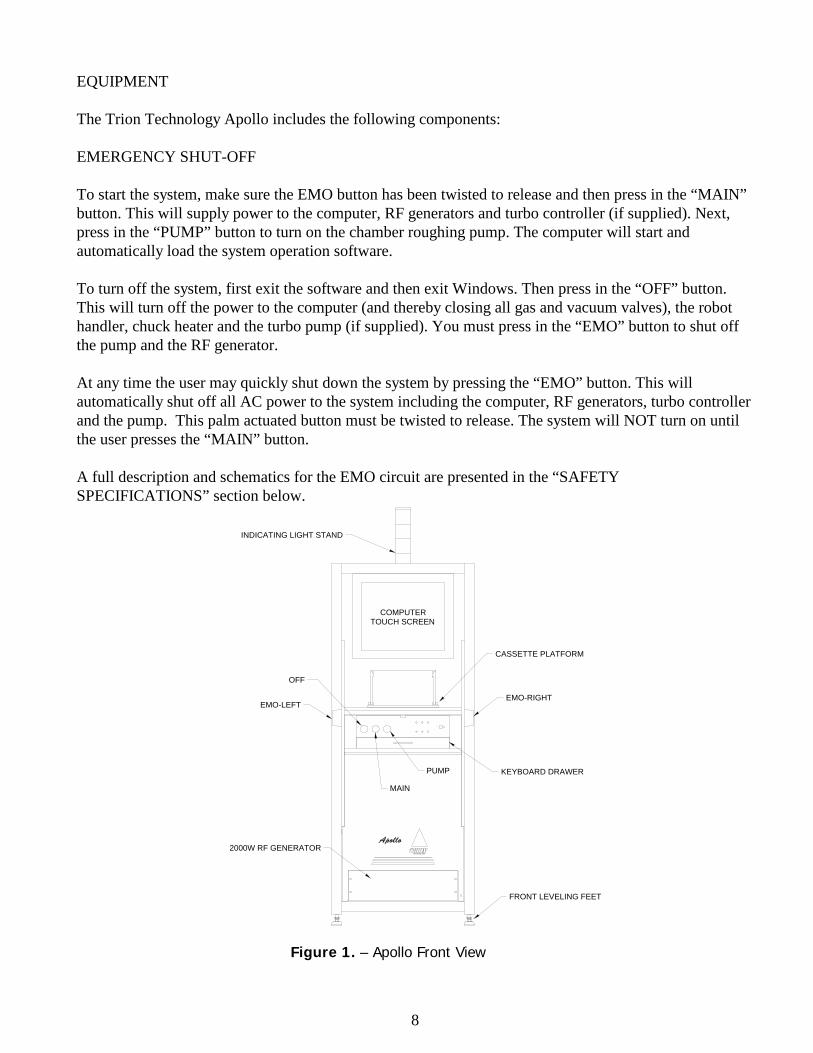
EQUIPMENT The Trion Technology Apollo includes the following components: EMERGENCY SHUT-OFF To start the system, make sure the EMO button has been twisted to release and then press in the “MAIN” button. This will supply power to the computer, RF generators and turbo controller (if supplied). Next, press in the “PUMP” button to turn on the chamber roughing pump. The computer will start and automatically load the system operation software. To turn off the system, first exit the software and then exit Windows. Then press in the “OFF” button. This will turn off the power to the computer (and thereby closing all gas and vacuum valves), the robot handler, chuck heater and the turbo pump (if supplied). You must press in the “EMO” button to shut off the pump and the RF generator. At any time the user may quickly shut down the system by pressing the “EMO” button. This will automatically shut off all AC power to the system including the computer, RF generators, turbo controller and the pump. This palm actuated button must be twisted to release. The system will NOT turn on until the user presses the “MAIN” button. A full description and schematics for the EMO circuit are presented in the “SAFETY SPECIFICATIONS” section below.
COMPUTERTOUCH SCREEN
OFF
MAIN
PUMP
CASSETTE PLATFORM
EMO-LEFTEMO-RIGHT
KEYBOARD DRAWER
2000W RF GENERATOR
FRONT LEVELING FEET
INDICATING LIGHT STAND
Figure 1. – Apollo Front View
9
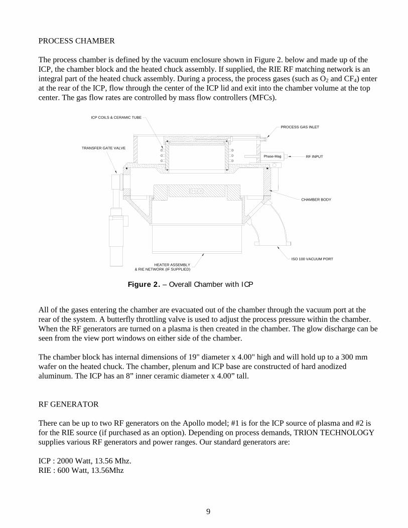
PROCESS CHAMBER The process chamber is defined by the vacuum enclosure shown in Figure 2. below and made up of the ICP, the chamber block and the heated chuck assembly. If supplied, the RIE RF matching network is an integral part of the heated chuck assembly. During a process, the process gases (such as O2 and CF4) enter at the rear of the ICP, flow through the center of the ICP lid and exit into the chamber volume at the top center. The gas flow rates are controlled by mass flow controllers (MFCs).
Phase-Mag
PROCESS GAS INLET
RF INPUT
ISO 100 VACUUM PORT
TRANSFER GATE VALVE
CHAMBER BODY
ICP COILS & CERAMIC TUBE
HEATER ASSEMBLY& RIE NETWORK (IF SUPPLIED)
All of the gases entering the chamber are evacuated out of the chamber through the vacuum port at the rear of the system. A butterfly throttling valve is used to adjust the process pressure within the chamber. When the RF generators are turned on a plasma is then created in the chamber. The glow discharge can be seen from the view port windows on either side of the chamber. The chamber block has internal dimensions of 19" diameter x 4.00" high and will hold up to a 300 mm wafer on the heated chuck. The chamber, plenum and ICP base are constructed of hard anodized aluminum. The ICP has an 8” inner ceramic diameter x 4.00” tall. RF GENERATOR There can be up to two RF generators on the Apollo model; #1 is for the ICP source of plasma and #2 is for the RIE source (if purchased as an option). Depending on process demands, TRION TECHNOLOGY supplies various RF generators and power ranges. Our standard generators are: ICP : 2000 Watt, 13.56 Mhz. RIE : 600 Watt, 13.56Mhz
ICP Matching Network
Figure 2. – Overall Chamber with ICP
10
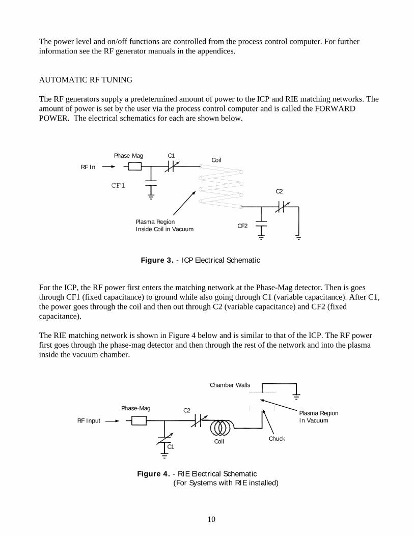
The power level and on/off functions are controlled from the process control computer. For further information see the RF generator manuals in the appendices. AUTOMATIC RF TUNING The RF generators supply a predetermined amount of power to the ICP and RIE matching networks. The amount of power is set by the user via the process control computer and is called the FORWARD POWER. The electrical schematics for each are shown below.
For the ICP, the RF power first enters the matching network at the Phase-Mag detector. Then is goes through CF1 (fixed capacitance) to ground while also going through C1 (variable capacitance). After C1, the power goes through the coil and then out through C2 (variable capacitance) and CF2 (fixed capacitance). The RIE matching network is shown in Figure 4 below and is similar to that of the ICP. The RF power first goes through the phase-mag detector and then through the rest of the network and into the plasma inside the vacuum chamber.
RF In
Phase-Mag C1
CF1
Coil
C2
CF2
Figure 3. - ICP Electrical Schematic
RF Input
Plasma Region Inside Coil in Vacuum
C1
C2
Chuck
Phase-Mag
Chamber Walls
Plasma Region In Vacuum
Coil
Figure 4. - RIE Electrical Schematic (For Systems with RIE installed)
11
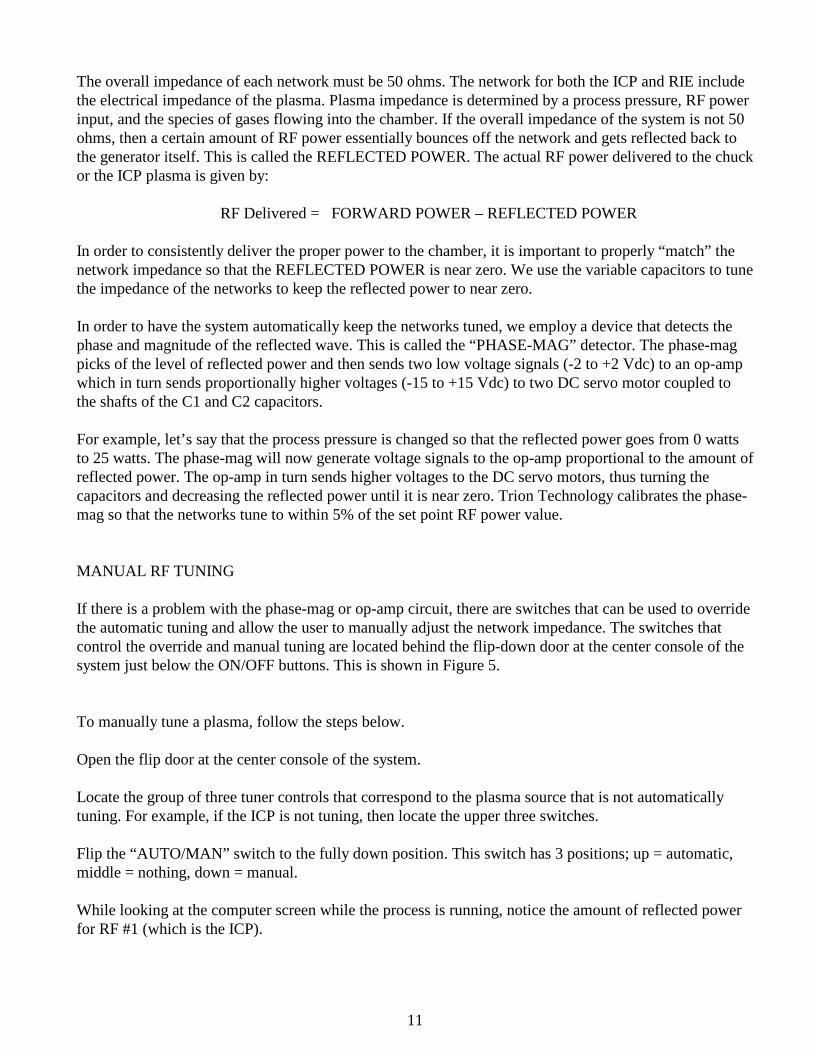
The overall impedance of each network must be 50 ohms. The network for both the ICP and RIE include the electrical impedance of the plasma. Plasma impedance is determined by a process pressure, RF power input, and the species of gases flowing into the chamber. If the overall impedance of the system is not 50 ohms, then a certain amount of RF power essentially bounces off the network and gets reflected back to the generator itself. This is called the REFLECTED POWER. The actual RF power delivered to the chuck or the ICP plasma is given by: RF Delivered = FORWARD POWER – REFLECTED POWER In order to consistently deliver the proper power to the chamber, it is important to properly “match” the network impedance so that the REFLECTED POWER is near zero. We use the variable capacitors to tune the impedance of the networks to keep the reflected power to near zero. In order to have the system automatically keep the networks tuned, we employ a device that detects the phase and magnitude of the reflected wave. This is called the “PHASE-MAG” detector. The phase-mag picks of the level of reflected power and then sends two low voltage signals (-2 to +2 Vdc) to an op-amp which in turn sends proportionally higher voltages (-15 to +15 Vdc) to two DC servo motor coupled to the shafts of the C1 and C2 capacitors. For example, let’s say that the process pressure is changed so that the reflected power goes from 0 watts to 25 watts. The phase-mag will now generate voltage signals to the op-amp proportional to the amount of reflected power. The op-amp in turn sends higher voltages to the DC servo motors, thus turning the capacitors and decreasing the reflected power until it is near zero. Trion Technology calibrates the phase-mag so that the networks tune to within 5% of the set point RF power value. MANUAL RF TUNING If there is a problem with the phase-mag or op-amp circuit, there are switches that can be used to override the automatic tuning and allow the user to manually adjust the network impedance. The switches that control the override and manual tuning are located behind the flip-down door at the center console of the system just below the ON/OFF buttons. This is shown in Figure 5. To manually tune a plasma, follow the steps below. Open the flip door at the center console of the system. Locate the group of three tuner controls that correspond to the plasma source that is not automatically tuning. For example, if the ICP is not tuning, then locate the upper three switches. Flip the “AUTO/MAN” switch to the fully down position. This switch has 3 positions; up = automatic, middle = nothing, down = manual. While looking at the computer screen while the process is running, notice the amount of reflected power for RF #1 (which is the ICP).
12
OFF MAIN PUMPUSB
AUTO
MANUAL C1 C2
C2C1MANUAL
AUTO
KEYBOARD DRAWER
CASSETTE PLATFORM
RIE TUNINGSWITCHES
ICP TUNINGSWITCHES
Figure 5. User Front Controls
Adjust the “C1” switch so that the reflected power decreases. This switch is momentary so when you release it, it will return to the center, or neutral position. If the reflected power increases, then reverse the direction on the switch. Keep adjusting this switch until the reflected power is at a minimum. Then adjust the “C2” switch in the same manner until the reflected power again goes to a minimum. Repeat steps 5 and 6 iteratively until the reflected power gets to near zero. Leave the “AUTO/MAN” switch in the manual (or down) position. Putting it back to the automatic position may increase the reflected power. PROCESS CONTROLLER The Apollo comes with a Pentium based process control computer with a touch screen user interface. The Trion designed data acquisition board has 16 analog output channels (12 bit resolution) which control the 4 gas channels, process pressure, chuck temperature, and the RF and/or Microwave power. The system also comes with 16 channels of 12 bit analog input. The DAQ board and controller are run by LabView on Windows XP software. All processing parameters can be programmed by the user and stored into recipes files on the hard drive and/or on a USB drive. Up to fifteen process steps per recipe can be stored. The system controller also has a manual process control section.
13
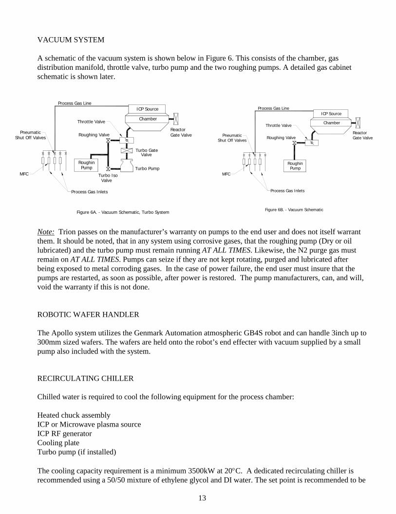
VACUUM SYSTEM A schematic of the vacuum system is shown below in Figure 6. This consists of the chamber, gas distribution manifold, throttle valve, turbo pump and the two roughing pumps. A detailed gas cabinet schematic is shown later.
RoughinPump Turbo Pump
Turbo GateValve
Roughing Valve
Turbo Iso Valve
Throttle ValveChamber
Process Gas Line
PneumaticShut Off Valves
MFC
Process Gas Inlets
ReactorGate Valve
ICP Source
Figure 6A. - Vacuum Schematic, Turbo System
RoughinPump
Roughing Valve
Throttle ValveChamber
Process Gas Line
PneumaticShut Off Valves
MFC
Process Gas Inlets
ReactorGate Valve
ICP Source
Figure 6B. - Vacuum Schematic
Note: Trion passes on the manufacturer’s warranty on pumps to the end user and does not itself warrant them. It should be noted, that in any system using corrosive gases, that the roughing pump (Dry or oil lubricated) and the turbo pump must remain running AT ALL TIMES. Likewise, the N2 purge gas must remain on AT ALL TIMES. Pumps can seize if they are not kept rotating, purged and lubricated after being exposed to metal corroding gases. In the case of power failure, the end user must insure that the pumps are restarted, as soon as possible, after power is restored. The pump manufacturers, can, and will, void the warranty if this is not done. ROBOTIC WAFER HANDLER The Apollo system utilizes the Genmark Automation atmospheric GB4S robot and can handle 3inch up to 300mm sized wafers. The wafers are held onto the robot’s end effecter with vacuum supplied by a small pump also included with the system. RECIRCULATING CHILLER Chilled water is required to cool the following equipment for the process chamber: Heated chuck assembly ICP or Microwave plasma source ICP RF generator Cooling plate Turbo pump (if installed) The cooling capacity requirement is a minimum 3500kW at 20°C. A dedicated recirculating chiller is recommended using a 50/50 mixture of ethylene glycol and DI water. The set point is recommended to be

14
25°C in order to prevent an possible condensation on the equipment. A recirculating chiller can be purchased from TRION as an option. House water is required for the dry pump vacuum pump. The exact temperature and flow rate specifications can be found in the facilities section of this manual.
15
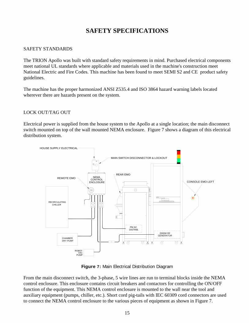
SAFETY SPECIFICATIONS SAFETY STANDARDS The TRION Apollo was built with standard safety requirements in mind. Purchased electrical components meet national UL standards where applicable and materials used in the machine's construction meet National Electric and Fire Codes. This machine has been found to meet SEMI S2 and CE product safety guidelines. The machine has the proper harmonized ANSI Z535.4 and ISO 3864 hazard warning labels located wherever there are hazards present on the system. LOCK OUT/TAG OUT Electrical power is supplied from the house system to the Apollo at a single location; the main disconnect switch mounted on top of the wall mounted NEMA enclosure. Figure 7 shows a diagram of this electrical distribution system.
BA D E
EMO
OFF
ON
EBA
RECIRCULATING
CHAMBERDRY PUMP
D
ROBOTVAC
PUMP
PM ACDISTRIB.
2000W RFGENERATOR
HOUSE SUPPLY ELECTRICAL
MAIN SWITCH DISCONNECTOR & LOCKOUT
REMOTE EMOCONSOLE EMO-LEFT
REAR EMO
CHILLER
ENCLOSURECONTROL
NEMA
Figure 7: Main Electrical Distribution Diagram From the main disconnect switch, the 3-phase, 5 wire lines are run to terminal blocks inside the NEMA control enclosure. This enclosure contains circuit breakers and contactors for controlling the ON/OFF function of the equipment. This NEMA control enclosure is mounted to the wall near the tool and auxiliary equipment (pumps, chiller, etc.). Short cord pig-tails with IEC 60309 cord connectors are used to connect the NEMA control enclosure to the various pieces of equipment as shown in Figure 7.
16
PROCEDURE FOR SERVICE: If any service work is to be performed on the system other than routine system maintenance, the user must first shut down the system as follows: Exit any running software Exit Windows XP Press the EMO button on the side of the system’s console. The main disconnect switch must then be rotated to the “OFF” position and locked out with a padlock. In addition a “DANGER DO NOT OPERATE” tag should be attached to the lock and visible. This will prevent any system component from turning on. It is now safe to remove modules and/or repair them in place following proper guidelines set down by TRION TECHNOLOGY. This includes the components inside the NEMA control enclosure and the process module (PM) AC distribution mounted to the inside of the tool. EMERGENCY OFF SYSTEM Figure 7 also shows the locations of the control and buttons and EMO locations. There are 3 control buttons and 4 EMO buttons on the Apollo system; MAIN, PUMP, OFF and EMO-LEFT, EMO-RIGHT, EMO-REAR and PUMP EMO. The operator station at the front of the console has access to the EMO-LEFT and EMO-RIGHT buttons. MAIN This button energizes the AC relay (K1) inside the process model AC distribution (ACD)
module and: - distributes 220VAC to the outlets [heater, heater control, Genmark robot] - turns on the computer and touch screen monitor PUMP This button energizes the relays (K1 through K4) inside the NEMA control enclosure.
The results of pressing this button are: - turns on the 3-phase chamber roughing pump - turns on the recirculating chiller - turns on the small robot vacuum pump - turns on the 3-phase RF generator
OFF This button de-energizes the AC relay (K1) inside the process model AC distribution and
therefore shuts off the following: - computer and touch screen monitor - heater and heater controller - Genmark robot handler - Turbo pump (if supplied)
All EMO buttons perform the same function; EMO This button de-energizes the AC relay (K1) inside the process module AC distribution and
all relays (K1 through K4) inside the NEMA control enclosure that in turn shuts off all components and instruments on the Apollo system.
17
INTERLOCKS The Apollo system has hardware interlocks that place the machine in a safe mode when tripped. These interlocks protect against a loss of water coolant flow and a loss of the house exhaust to the gas cabinet and pumps. The table below describes the interlocks, their location and what they control in the advent of an error or alarm condition.
Interlock Location Purpose Actions Water flow switch.
Mounted to the chamber coolant outlet port.
To detect a loss of water coolant flow.
N.C. switch opens when the water flow stops. This tells the computer to shut down the gas valves, RF power and turns off the heater.
Lid switch Mounted to the chamber ICP lid hinge at the rear of the chamber.
To detect if the lid is fully closed.
N.O. switch closes only when the chamber lid is fully closed. If the lid is not closed the RF interlock string is not satisfied and no RF output can be generated.
EQUIPMENT ELECTRICAL DESIGN All of the Apollo modules have been designed to be easily removed from the system. This design allows the user or the service engineer to remove and replace the module without exposing any electrical components. Internal to the Apollo modules, all components with voltages greater than 24 Volts have either protective plastic or metal covers. The electrical distribution modules (process module AC distribution and the NEMA control enclosure) have no user serviceable parts ads required tools to facilitate access. All covers that house dangerous voltage have ISO 3864 compliant warning labels which include the follow symbol:
All electrical components, wiring, and grounding comply with the National Electrical Code (NEC) for the US, and the 73/23/EEC Low Voltage Directive. CHEMICAL USE Although the typical process gas used for photo resist stripping is oxygen the following gases CAN be used in the Apollo system:
18
CF4 500 sccm maximum O2 500 sccm maximum Ar 500 sccm maximum SF6 500 sccm maximum
CHF3 500 sccm maximum When the etch process is complete, the process controller automatically maintains a vacuum in the chamber for 20 seconds after processing to insure complete removal of any residual by-products. (This time can be increased through software if desired). A follow on process step can be added that purges the chamber with nitrogen to further clear out residual gases. EMISSIONS There should be no harmful chemical emission during the normal operation of this equipment. The reaction chamber and vacuum pumps are sufficiently exhausted (per the required facilitation by the customer) to prevent this occurrence. LABELING All system wiring is color coded in accordance to NEC and CE requirements. All hazardous locations are labeled with harmonized ANSI Z535.4 and ISO 3864 compliant labels. EARTHQUAKE PROTECTION The assembled system will not overbalance until it is tipped more than 22o and is sturdily built into a 45mm square extruded aluminum frame. For further earthquake protection it is recommended that the system be bolted to the facility floor. MECHANICAL SAFETY There are no sharp protruding edges which can be hazardous. There are no externally accessible moving parts on the system. The area of the Genmark robot handler is secured with see-through plastic covers that require tools to remove. In addition the Pinch Hazard warning labels are located within this enclosure.
19
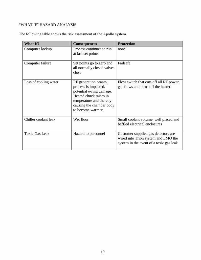
“WHAT IF” HAZARD ANALYSIS The following table shows the risk assessment of the Apollo system.
What If? Consequences Protection Computer lockup Process continues to run
at last set points
none
Computer failure Set points go to zero and all normally closed valves close
Failsafe
Loss of cooling water RF generation ceases, process is impacted, potential o-ring damage. Heated chuck raises in temperature and thereby causing the chamber body to become warmer.
Flow switch that cuts off all RF power, gas flows and turns off the heater.
Chiller coolant leak Wet floor Small coolant volume, well placed and baffled electrical enclosures
Toxic Gas Leak Hazard to personnel Customer supplied gas detectors are wired into Trion system and EMO the system in the event of a toxic gas leak
20
INSTALLATION INSPECTION The Apollo is completely tested and inspected at the factory before shipping. It is packed in specially designed shipping containers to protect it from damage in normal handling. Inspect the shipping containers before unpacking the instrument. If there are signs of damage to the containers, make note of the damage and report it to the shipping company and TRION TECHNOLOGY immediately. Inspect the instrument for any damage to the enclosure, the chamber, switches, and other components. If there are any damaged or missing components, notify your sales representative or the TRION Service Department as soon as possible. FACILITIES The facilities required for the operation of the Apollo are summarized in Appendix A. This is an example only. The exact quantities and sizes required for an installation will depend upon the exact purchase order specification. The Trion Technology service department will put together the design package for facilitation after the order has been received and the tool is being built. INSTALLATION PROCEDURE The following is a representative plan for installing the Apollo system. The are two major sections of the Apollo tool; 1) the process module and 2) the console and handler section. These two are separated and shipped in separate crates.
1. Position the process module in the room and use the leveling feet on the bottom of each of four legs to level the chamber.
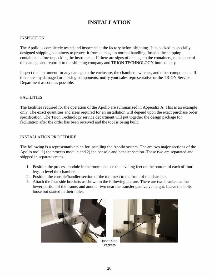
2. Position the console/handler section of the tool next to the front of the chamber. 3. Attach the four side brackets as shown in the following picture. There are two brackets at the
lower portion of the frame, and another two near the transfer gate valve height. Leave the bolts loose but started in their holes.
Upper Side Brackets
21
4. Once the two sections are together, level the console/handler section using its leveling feet. 5. Once the handler is leveled, then tighten the bolts on the side brackets so that the two sections are
securely held together. 6. The indicating light tower is shipped inside the upper section of the handler. Install this into the
upper front horizontal frame piece so the that light tower extends through the square cut-out in the sheet metal.
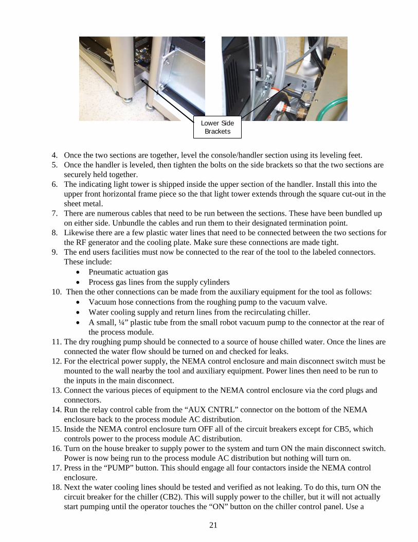
7. There are numerous cables that need to be run between the sections. These have been bundled up on either side. Unbundle the cables and run them to their designated termination point.
8. Likewise there are a few plastic water lines that need to be connected between the two sections for the RF generator and the cooling plate. Make sure these connections are made tight.
9. The end users facilities must now be connected to the rear of the tool to the labeled connectors. These include:
• Pneumatic actuation gas • Process gas lines from the supply cylinders
10. Then the other connections can be made from the auxiliary equipment for the tool as follows: • Vacuum hose connections from the roughing pump to the vacuum valve. • Water cooling supply and return lines from the recirculating chiller. • A small, ¼” plastic tube from the small robot vacuum pump to the connector at the rear of
the process module. 11. The dry roughing pump should be connected to a source of house chilled water. Once the lines are
connected the water flow should be turned on and checked for leaks. 12. For the electrical power supply, the NEMA control enclosure and main disconnect switch must be
mounted to the wall nearby the tool and auxiliary equipment. Power lines then need to be run to the inputs in the main disconnect.
13. Connect the various pieces of equipment to the NEMA control enclosure via the cord plugs and connectors.
14. Run the relay control cable from the “AUX CNTRL” connector on the bottom of the NEMA enclosure back to the process module AC distribution.
15. Inside the NEMA control enclosure turn OFF all of the circuit breakers except for CB5, which controls power to the process module AC distribution.
16. Turn on the house breaker to supply power to the system and turn ON the main disconnect switch. Power is now being run to the process module AC distribution but nothing will turn on.
17. Press in the “PUMP” button. This should engage all four contactors inside the NEMA control enclosure.
18. Next the water cooling lines should be tested and verified as not leaking. To do this, turn ON the circuit breaker for the chiller (CB2). This will supply power to the chiller, but it will not actually start pumping until the operator touches the “ON” button on the chiller control panel. Use a
Lower Side Brackets
22
second person to inspect the various water connections recently made (between the two sections and at the rear of the process module). Turn on the water flow and inspect for leaks. If any leaks, immediately stop the chiller’s pump and correct. Once the system is verified as being leak free leave the chiller running.
19. Turn on the pneumatic actuation gas and make sure the pressure is 80psig [5.5bar] 20. Turn on the small robot vacuum pump by switching CB4 to the ON position. 21. The next step is to urn on the roughing pump. However the rotation of the motor must be check to
ensure that the inlet is sucking and not blowing air. This should be done by the Trion Technology service technician or a representative of the pump vendor. To turn on the pump’s power switch circuit breaker CB1 to the ON position.
22. Now again at the operators console location, press in the “MAIN” button to activate the process module AC distribution. This will consequently turn on the computer, Genmark robot and heater controller. The software will automatically start to boot.
23. When the software starts, it will first home the robot and the seal the process chamber and begin to pump it down.
24. The gas lines can be checked with the Apollo system by using the Manual Process Control portion of the software (described below) to evacuate these lines with the roughing pump. Once the lines have been verified as leak tight the gas cylinders can be opened.
25. Finally, the circuit breaker (CB3) for the RF power supply should be switched on inside the NEMA control enclosure.
RF WARNING
This machine uses RF frequency power. Care should be taken in its use. DO NOT operate this machine with any RF component enclosures open. These components should be service by trained personnel only. The frequency and power levels of the RF generators are as follows: ICP RF generator 2000 Watts maximum power @ 13.56Mhz RIE RF generator (if supplied) 600 Watts maximum power @ 13.56Mhz Microwave Power 1500Wattss maximum power
23
PROCESS CONTROLLER OPERATION
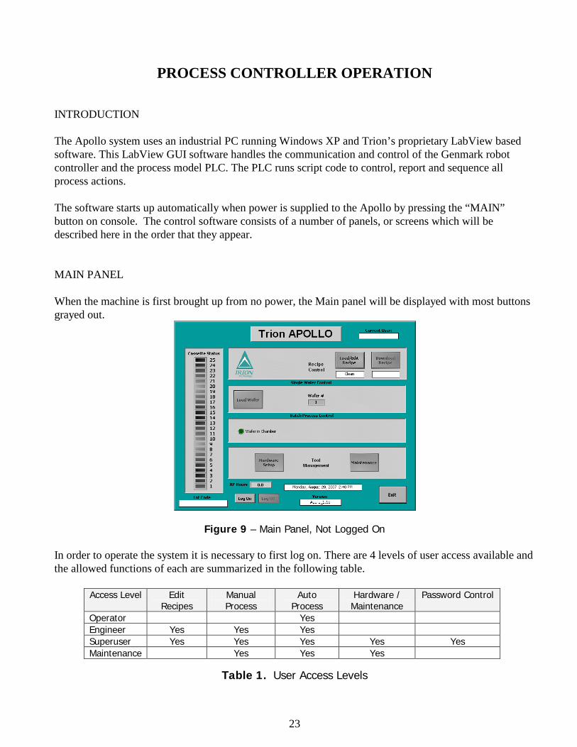
INTRODUCTION The Apollo system uses an industrial PC running Windows XP and Trion’s proprietary LabView based software. This LabView GUI software handles the communication and control of the Genmark robot controller and the process model PLC. The PLC runs script code to control, report and sequence all process actions. The software starts up automatically when power is supplied to the Apollo by pressing the “MAIN” button on console. The control software consists of a number of panels, or screens which will be described here in the order that they appear. MAIN PANEL When the machine is first brought up from no power, the Main panel will be displayed with most buttons grayed out.
Figure 9 – Main Panel, Not Logged On
In order to operate the system it is necessary to first log on. There are 4 levels of user access available and the allowed functions of each are summarized in the following table.
Access Level Edit Recipes
Manual Process
Auto Process
Hardware / Maintenance
Password Control
Operator Yes Engineer Yes Yes Yes Superuser Yes Yes Yes Yes Yes Maintenance Yes Yes Yes
Table 1. User Access Levels
24
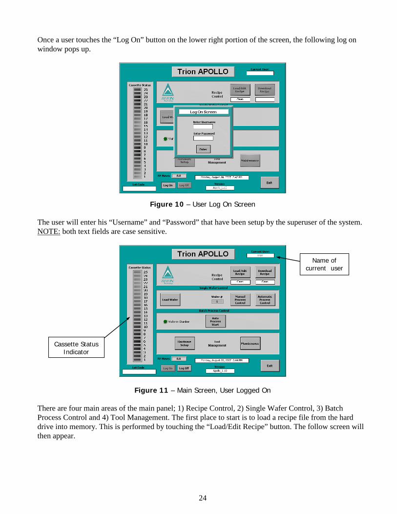
Once a user touches the “Log On” button on the lower right portion of the screen, the following log on window pops up.
Figure 10 – User Log On Screen The user will enter his “Username” and “Password” that have been setup by the superuser of the system. NOTE: both text fields are case sensitive.
Figure 11 – Main Screen, User Logged On There are four main areas of the main panel; 1) Recipe Control, 2) Single Wafer Control, 3) Batch Process Control and 4) Tool Management. The first place to start is to load a recipe file from the hard drive into memory. This is performed by touching the “Load/Edit Recipe” button. The follow screen will then appear.
Name of current user
Cassette Status Indicator
25
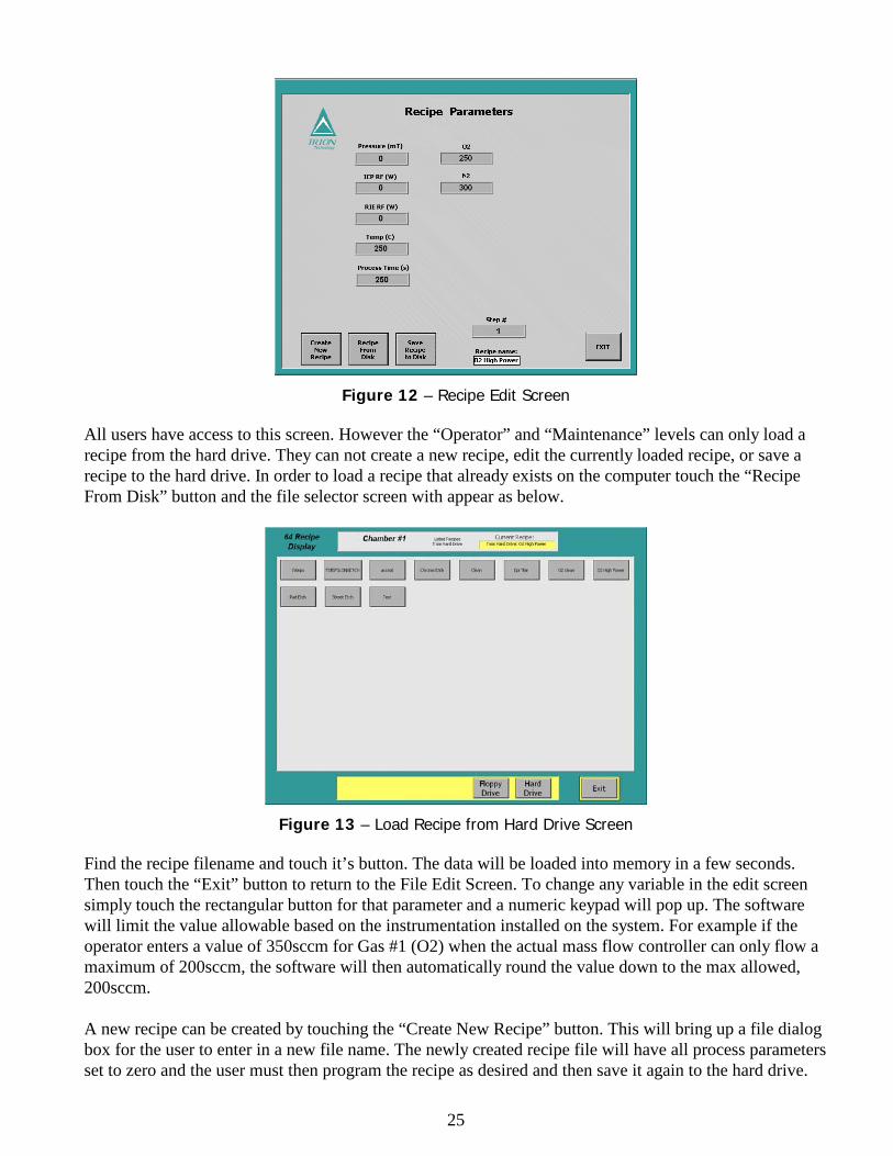
Figure 12 – Recipe Edit Screen All users have access to this screen. However the “Operator” and “Maintenance” levels can only load a recipe from the hard drive. They can not create a new recipe, edit the currently loaded recipe, or save a recipe to the hard drive. In order to load a recipe that already exists on the computer touch the “Recipe From Disk” button and the file selector screen with appear as below.
Figure 13 – Load Recipe from Hard Drive Screen Find the recipe filename and touch it’s button. The data will be loaded into memory in a few seconds. Then touch the “Exit” button to return to the File Edit Screen. To change any variable in the edit screen simply touch the rectangular button for that parameter and a numeric keypad will pop up. The software will limit the value allowable based on the instrumentation installed on the system. For example if the operator enters a value of 350sccm for Gas #1 (O2) when the actual mass flow controller can only flow a maximum of 200sccm, the software will then automatically round the value down to the max allowed, 200sccm. A new recipe can be created by touching the “Create New Recipe” button. This will bring up a file dialog box for the user to enter in a new file name. The newly created recipe file will have all process parameters set to zero and the user must then program the recipe as desired and then save it again to the hard drive.
26
Each recipe file can have up to 16 separate process steps. In order to include the next step into a process sequence a non-zero process time value must be entered. For example if you wish to have a two step process then both step #1 and #2 must have a non-zero time entry AND the process time for step #3 must be set to zero. However, the process controller will not skip over steps, meaning that in the above example if setpoint #4 has a non-zero process time, the controller will still stop after step #2. A quick definition of the process controller sequence and how it relates to these process steps is in order here. When the process controller is started in an automatic run mode each step follows the sequence below;
1. Pump the chamber down from atmosphere to a base pressure (~500mT) 2. Turn on any programmed gas flows. If the gas flow set point it left at zero, then no gases will be
turned on but the process will continue. 3. Wait for the gas flow and pressure to adjust to their programmed values. 4. Turn on the RF and start counting down from the process time set point to zero. 5. Once the timer reaches zero the RF power turns off, the gases shut off and the throttle valve opens
fully to pump out the residual gas and reaction byproducts from the chamber 6. After a 5 second pump out time, the PLC “looks” at the time entry of the next step. If it is zero
then the automatic process mode stops and returns to the main screen. If the process time entry is non-zero, then the controller loads in the next step’s parameters and cycles back through the above sequence.
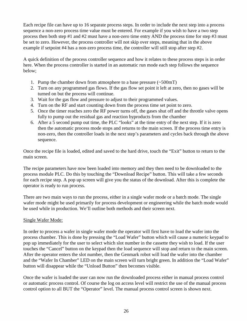
Once the recipe file is loaded, edited and saved to the hard drive, touch the “Exit” button to return to the main screen. The recipe parameters have now been loaded into memory and they then need to be downloaded to the process module PLC. Do this by touching the “Download Recipe” button. This will take a few seconds for each recipe step. A pop up screen will give you the status of the download. After this is complete the operator is ready to run process. There are two main ways to run the process, either in a single wafer mode or a batch mode. The single wafer mode might be used primarily for process development or engineering while the batch mode would be used while in production. We’ll outline both methods and their screen next. Single Wafer Mode: In order to process a wafer in single wafer mode the operator will first have to load the wafer into the process chamber. This is done by pressing the “Load Wafer” button which will cause a numeric keypad to pop up immediately for the user to select which slot number in the cassette they wish to load. If the user touches the “Cancel” button on the keypad then the load sequence will stop and return to the main screen. After the operator enters the slot number, then the Genmark robot will load the wafer into the chamber and the “Wafer In Chamber” LED on the main screen will turn bright green. In addition the “Load Wafer” button will disappear while the “Unload Button” then becomes visible. Once the wafer is loaded the user can now run the downloaded process either in manual process control or automatic process control. Of course the log on access level will restrict the use of the manual process control option to all BUT the “Operator” level. The manual process control screen is shown next.
27
Figure 14 – Manual Process Control Screen This screen is broken up into two main sections; 1) process variables and 2) control buttons. The process variable section shows the set point value and the current instrumentation reading side-by-side for each variable. Each process variable can be changed in this screen in-situ by touching the rectangular data field for the “SET” point for a particular variable. This again will pop up the numeric keypad. The currently running step can be instantly changed by touching the Left and Right buttons next to the step # display value. The control section allows the operator to control the process sequence step by step. The first button on the left of the screen “Vacuum” opens and closes the isolation valve between the chamber and the roughing pump. When this button is GREEN (OPEN) the valve is open and the chamber is being pumped down. The second button is the “Pressure Iso” and controls a small pneumatic valve that isolates the capacitance manometer from the chamber. When this is GREEN (OPEN) the pressure isolation valve is open and the Baratron gauge is reading the chamber pressure. Once both of these buttons are ON then the next control in the sequence “Gas On” becomes visible. When this button is turned ON (GREEN) then the programmed gas valves open and the mass flow controllers adjust to their set point. The throttle valve also adjusts the pressure to it’s set point. In addition the “RF On” button becomes visible. Once the “RF On” button is GREEN (ON) the RF generator will output power and a plasma should strike in the chamber. The process time counter will begin counting upwards from zero. WARNING! In manual process control mode the process will NOT shut off automatically. The user MUST turn off the RF manually for the etch to stop. At any point in manual mode any process variable can be changed in-situ. For example, if the gases are flowing and the RF is on, the user can still change the RF power set point is they so choose. The following table summarizes the states and actions taken for the various control buttons on this manual process control screen.
28
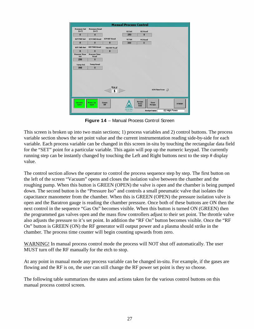
Control Button State Tool Actions
Vacuum CLOSED Vacuum valve between chamber and roughing pump closes.
OPEN Vacuum valve between chamber and roughing opens and chamber gets pumped down. ICP should be closed.
Press Iso CLOSED Pneumatic isolation valve on capacitance manometer closes and isolates the gauge from the chamber.
OPEN Pneumatic isolation valve on capacitance manometer opens and the gauge now can read the true chamber pressure.
Gas OFF Closes all gas pneumatic valves, sets the analog control points at the MFCs (mass flow controllers) to zero and opens the throttle valve fully.
ON Opens the called for gas channel’s pneumatic shut-off valves, sends the analog set point control signal to the MFCs and commands the throttle valve to adjust pressure to the set point.
RF OFF Turns off the RF output from the generator. Resets the process timer to zero.
ON Turns on the RF output from the generator. Process timer begins counting up from zero in 1 second increments.
Table 2. Manual Control Button Summary There are also recipe file management buttons on this screen “Load” and “Save” recipe. These functions are just like those on the File Edit Recipe screen. Changes made to the process variables in this manual process control screen can be saved to hard drive by using the “Save Recipe” button. This will also automatically download the recipe data to the PLC. When the operator exits the manual process control screen the following action occur:
• Turns off RF power (if currently ON) • Turn off any gases still flowing • Leaves both the vacuum valve and pressure isolation valve as they are (either ON or OFF)
depending on the states of their control buttons. • Leaves the last temperature set point at the heater controller.
The second mode of process control is automatic control which is accessed from the main screen by touching the “Automatic Process Control” button. When the operator starts this mode the following screen is displayed.
29
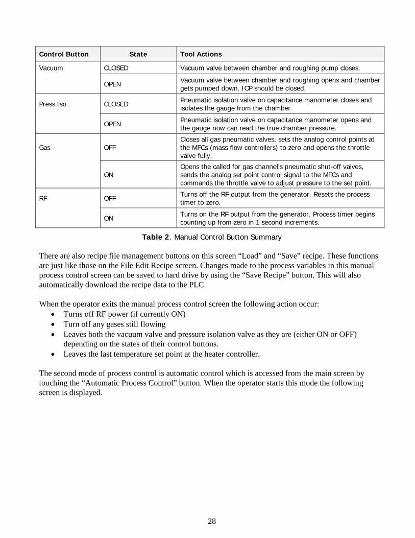
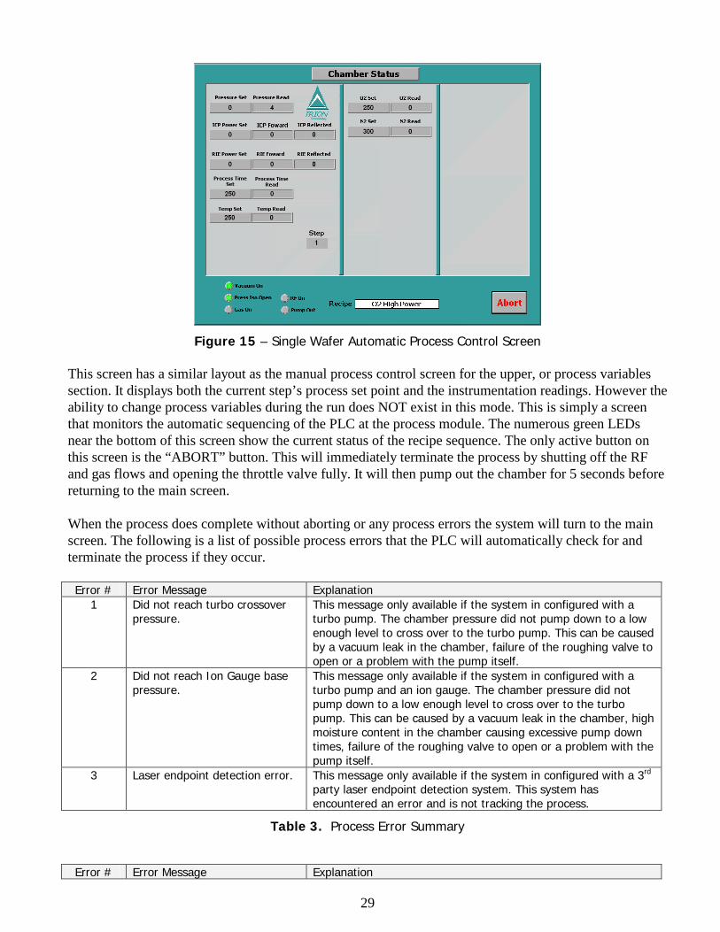
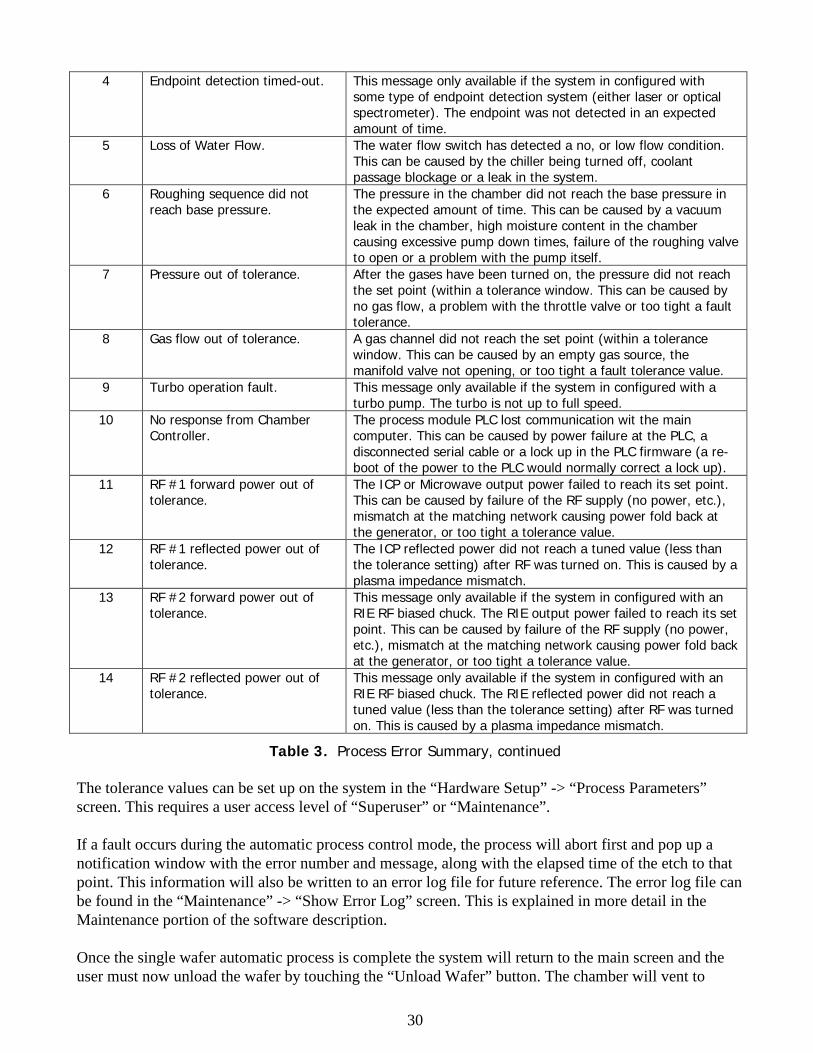
Figure 15 – Single Wafer Automatic Process Control Screen This screen has a similar layout as the manual process control screen for the upper, or process variables section. It displays both the current step’s process set point and the instrumentation readings. However the ability to change process variables during the run does NOT exist in this mode. This is simply a screen that monitors the automatic sequencing of the PLC at the process module. The numerous green LEDs near the bottom of this screen show the current status of the recipe sequence. The only active button on this screen is the “ABORT” button. This will immediately terminate the process by shutting off the RF and gas flows and opening the throttle valve fully. It will then pump out the chamber for 5 seconds before returning to the main screen. When the process does complete without aborting or any process errors the system will turn to the main screen. The following is a list of possible process errors that the PLC will automatically check for and terminate the process if they occur. Error # Error Message Explanation
1 Did not reach turbo crossover pressure.
This message only available if the system in configured with a turbo pump. The chamber pressure did not pump down to a low enough level to cross over to the turbo pump. This can be caused by a vacuum leak in the chamber, failure of the roughing valve to open or a problem with the pump itself.
2 Did not reach Ion Gauge base pressure.
This message only available if the system in configured with a turbo pump and an ion gauge. The chamber pressure did not pump down to a low enough level to cross over to the turbo pump. This can be caused by a vacuum leak in the chamber, high moisture content in the chamber causing excessive pump down times, failure of the roughing valve to open or a problem with the pump itself.
3 Laser endpoint detection error. This message only available if the system in configured with a 3rd party laser endpoint detection system. This system has encountered an error and is not tracking the process.
Table 3. Process Error Summary Error # Error Message Explanation
30
4 Endpoint detection timed-out. This message only available if the system in configured with some type of endpoint detection system (either laser or optical spectrometer). The endpoint was not detected in an expected amount of time.
5 Loss of Water Flow. The water flow switch has detected a no, or low flow condition. This can be caused by the chiller being turned off, coolant passage blockage or a leak in the system.
6 Roughing sequence did not reach base pressure.
The pressure in the chamber did not reach the base pressure in the expected amount of time. This can be caused by a vacuum leak in the chamber, high moisture content in the chamber causing excessive pump down times, failure of the roughing valve to open or a problem with the pump itself.
7 Pressure out of tolerance. After the gases have been turned on, the pressure did not reach the set point (within a tolerance window. This can be caused by no gas flow, a problem with the throttle valve or too tight a fault tolerance.
8 Gas flow out of tolerance. A gas channel did not reach the set point (within a tolerance window. This can be caused by an empty gas source, the manifold valve not opening, or too tight a fault tolerance value.
9 Turbo operation fault. This message only available if the system in configured with a turbo pump. The turbo is not up to full speed.
10 No response from Chamber Controller.
The process module PLC lost communication wit the main computer. This can be caused by power failure at the PLC, a disconnected serial cable or a lock up in the PLC firmware (a re-boot of the power to the PLC would normally correct a lock up).
11 RF #1 forward power out of tolerance.
The ICP or Microwave output power failed to reach its set point. This can be caused by failure of the RF supply (no power, etc.), mismatch at the matching network causing power fold back at the generator, or too tight a tolerance value.
12 RF #1 reflected power out of tolerance.
The ICP reflected power did not reach a tuned value (less than the tolerance setting) after RF was turned on. This is caused by a plasma impedance mismatch.
13 RF #2 forward power out of tolerance.
This message only available if the system in configured with an RIE RF biased chuck. The RIE output power failed to reach its set point. This can be caused by failure of the RF supply (no power, etc.), mismatch at the matching network causing power fold back at the generator, or too tight a tolerance value.
14 RF #2 reflected power out of tolerance.
This message only available if the system in configured with an RIE RF biased chuck. The RIE reflected power did not reach a tuned value (less than the tolerance setting) after RF was turned on. This is caused by a plasma impedance mismatch.
Table 3. Process Error Summary, continued The tolerance values can be set up on the system in the “Hardware Setup” -> “Process Parameters” screen. This requires a user access level of “Superuser” or “Maintenance”. If a fault occurs during the automatic process control mode, the process will abort first and pop up a notification window with the error number and message, along with the elapsed time of the etch to that point. This information will also be written to an error log file for future reference. The error log file can be found in the “Maintenance” -> “Show Error Log” screen. This is explained in more detail in the Maintenance portion of the software description. Once the single wafer automatic process is complete the system will return to the main screen and the user must now unload the wafer by touching the “Unload Wafer” button. The chamber will vent to
31
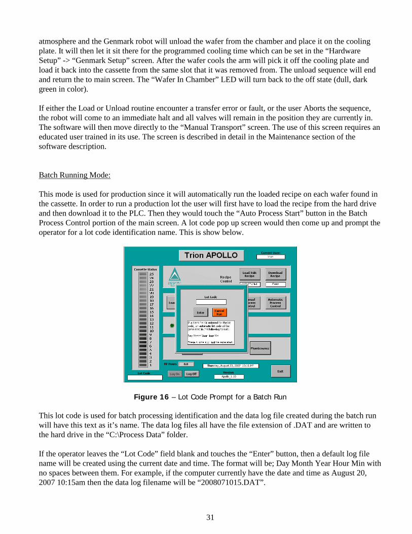
atmosphere and the Genmark robot will unload the wafer from the chamber and place it on the cooling plate. It will then let it sit there for the programmed cooling time which can be set in the “Hardware Setup” -> “Genmark Setup” screen. After the wafer cools the arm will pick it off the cooling plate and load it back into the cassette from the same slot that it was removed from. The unload sequence will end and return the to main screen. The “Wafer In Chamber” LED will turn back to the off state (dull, dark green in color). If either the Load or Unload routine encounter a transfer error or fault, or the user Aborts the sequence, the robot will come to an immediate halt and all valves will remain in the position they are currently in. The software will then move directly to the “Manual Transport” screen. The use of this screen requires an educated user trained in its use. The screen is described in detail in the Maintenance section of the software description. Batch Running Mode: This mode is used for production since it will automatically run the loaded recipe on each wafer found in the cassette. In order to run a production lot the user will first have to load the recipe from the hard drive and then download it to the PLC. Then they would touch the “Auto Process Start” button in the Batch Process Control portion of the main screen. A lot code pop up screen would then come up and prompt the operator for a lot code identification name. This is show below.
Figure 16 – Lot Code Prompt for a Batch Run This lot code is used for batch processing identification and the data log file created during the batch run will have this text as it’s name. The data log files all have the file extension of .DAT and are written to the hard drive in the “C:\Process Data” folder. If the operator leaves the “Lot Code” field blank and touches the “Enter” button, then a default log file name will be created using the current date and time. The format will be; Day Month Year Hour Min with no spaces between them. For example, if the computer currently have the date and time as August 20, 2007 10:15am then the data log filename will be “2008071015.DAT”.
32
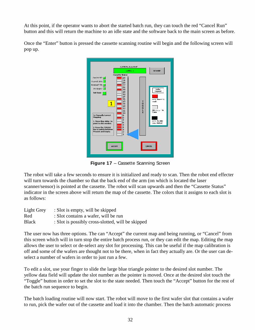
At this point, if the operator wants to abort the started batch run, they can touch the red “Cancel Run” button and this will return the machine to an idle state and the software back to the main screen as before. Once the “Enter” button is pressed the cassette scanning routine will begin and the following screen will pop up.
Figure 17 – Cassette Scanning Screen The robot will take a few seconds to ensure it is initialized and ready to scan. Then the robot end effecter will turn towards the chamber so that the back end of the arm (on which is located the laser scanner/sensor) is pointed at the cassette. The robot will scan upwards and then the “Cassette Status” indicator in the screen above will return the map of the cassette. The colors that it assigns to each slot is as follows: Light Grey : Slot is empty, will be skipped Red : Slot contains a wafer, will be run Black : Slot is possibly cross-slotted, will be skipped The user now has three options. The can “Accept” the current map and being running, or “Cancel” from this screen which will in turn stop the entire batch process run, or they can edit the map. Editing the map allows the user to select or de-select any slot for processing. This can be useful if the map calibration is off and some of the wafers are thought not to be there, when in fact they actually are. Or the user can de-select a number of wafers in order to just run a few. To edit a slot, use your finger to slide the large blue triangle pointer to the desired slot number. The yellow data field will update the slot number as the pointer is moved. Once at the desired slot touch the “Toggle” button in order to set the slot to the state needed. Then touch the “Accept” button for the rest of the batch run sequence to begin. The batch loading routine will now start. The robot will move to the first wafer slot that contains a wafer to run, pick the wafer out of the cassette and load it into the chamber. Then the batch automatic process
33
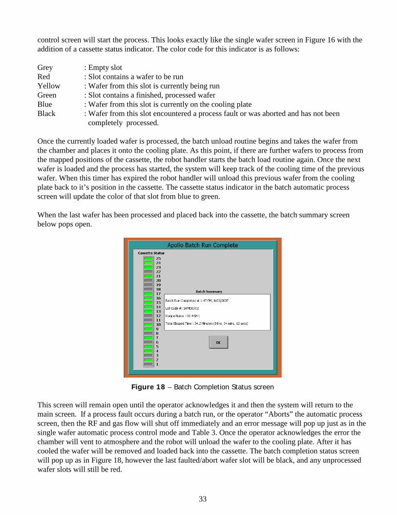
control screen will start the process. This looks exactly like the single wafer screen in Figure 16 with the addition of a cassette status indicator. The color code for this indicator is as follows: Grey : Empty slot Red : Slot contains a wafer to be run Yellow : Wafer from this slot is currently being run Green : Slot contains a finished, processed wafer Blue : Wafer from this slot is currently on the cooling plate Black : Wafer from this slot encountered a process fault or was aborted and has not been
completely processed. Once the currently loaded wafer is processed, the batch unload routine begins and takes the wafer from the chamber and places it onto the cooling plate. As this point, if there are further wafers to process from the mapped positions of the cassette, the robot handler starts the batch load routine again. Once the next wafer is loaded and the process has started, the system will keep track of the cooling time of the previous wafer. When this timer has expired the robot handler will unload this previous wafer from the cooling plate back to it’s position in the cassette. The cassette status indicator in the batch automatic process screen will update the color of that slot from blue to green. When the last wafer has been processed and placed back into the cassette, the batch summary screen below pops open.
Figure 18 – Batch Completion Status screen This screen will remain open until the operator acknowledges it and then the system will return to the main screen. If a process fault occurs during a batch run, or the operator “Aborts” the automatic process screen, then the RF and gas flow will shut off immediately and an error message will pop up just as in the single wafer automatic process control mode and Table 3. Once the operator acknowledges the error the chamber will vent to atmosphere and the robot will unload the wafer to the cooling plate. After it has cooled the wafer will be removed and loaded back into the cassette. The batch completion status screen will pop up as in Figure 18, however the last faulted/abort wafer slot will be black, and any unprocessed wafer slots will still be red.
34
Also, as in the case of the single wafer load and unload, if a motion fault occurs, or the operator aborts the wafer transfer for any reason, then the robot will immediately halt and valves will remain in their state. The software will then move to the “Manual Transport” screen. Here the trained maintenance personnel can handle any motion errors and recover any wafer left on the chuck or cooling plate. In this case the batch summary screen will not be displayed. However, the cassette status indicator on the main screen will have the latest data and this can be used to discern what wafers were fully processed and which were not. Hardware Setup & Maintenance This section describes in detail the various sub-screens in the two areas accessed from the main screen by touching either the “Hardware Setup” or Maintenance” buttons. Again, the only access levels that can move into these areas are the “Superuser” and “Maintenance”.
35
TYPICAL PROCESS CONDITIONS
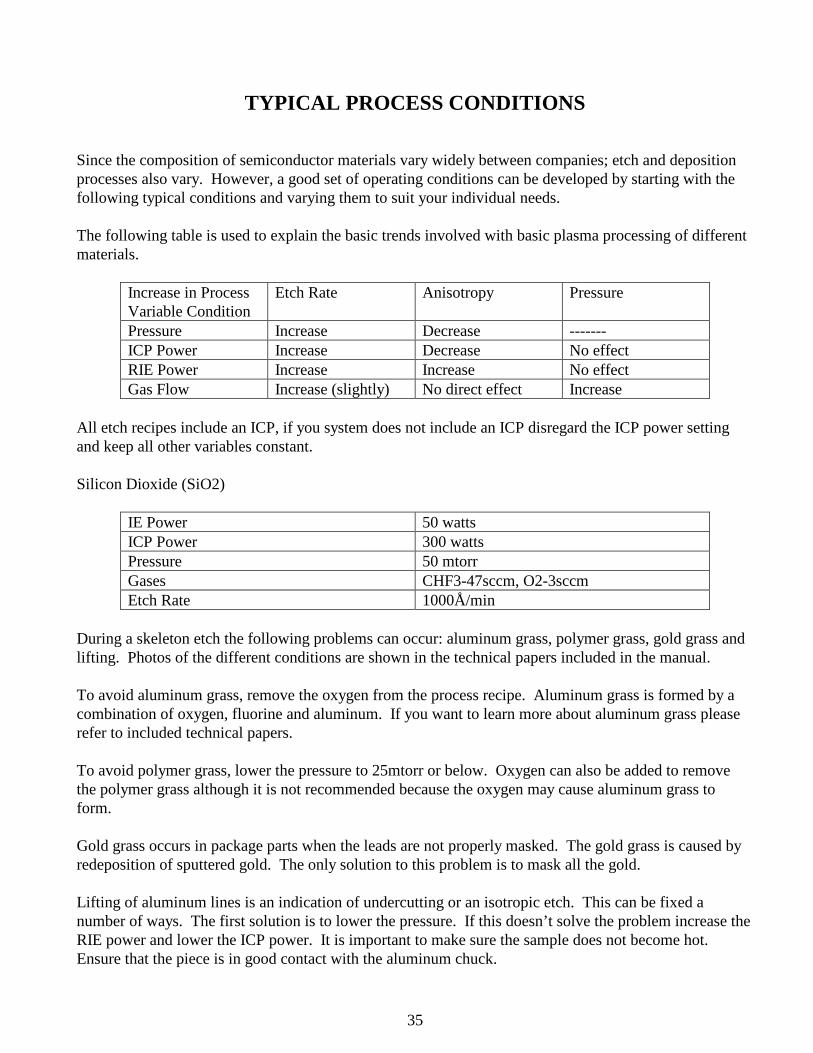
Since the composition of semiconductor materials vary widely between companies; etch and deposition processes also vary. However, a good set of operating conditions can be developed by starting with the following typical conditions and varying them to suit your individual needs. The following table is used to explain the basic trends involved with basic plasma processing of different materials.
Increase in Process Variable Condition
Etch Rate Anisotropy Pressure
Pressure Increase Decrease ------- ICP Power Increase Decrease No effect RIE Power Increase Increase No effect Gas Flow Increase (slightly) No direct effect Increase
All etch recipes include an ICP, if you system does not include an ICP disregard the ICP power setting and keep all other variables constant. Silicon Dioxide (SiO2)
IE Power 50 watts ICP Power 300 watts Pressure 50 mtorr Gases CHF3-47sccm, O2-3sccm Etch Rate 1000Å/min
During a skeleton etch the following problems can occur: aluminum grass, polymer grass, gold grass and lifting. Photos of the different conditions are shown in the technical papers included in the manual. To avoid aluminum grass, remove the oxygen from the process recipe. Aluminum grass is formed by a combination of oxygen, fluorine and aluminum. If you want to learn more about aluminum grass please refer to included technical papers. To avoid polymer grass, lower the pressure to 25mtorr or below. Oxygen can also be added to remove the polymer grass although it is not recommended because the oxygen may cause aluminum grass to form. Gold grass occurs in package parts when the leads are not properly masked. The gold grass is caused by redeposition of sputtered gold. The only solution to this problem is to mask all the gold. Lifting of aluminum lines is an indication of undercutting or an isotropic etch. This can be fixed a number of ways. The first solution is to lower the pressure. If this doesn’t solve the problem increase the RIE power and lower the ICP power. It is important to make sure the sample does not become hot. Ensure that the piece is in good contact with the aluminum chuck.
36
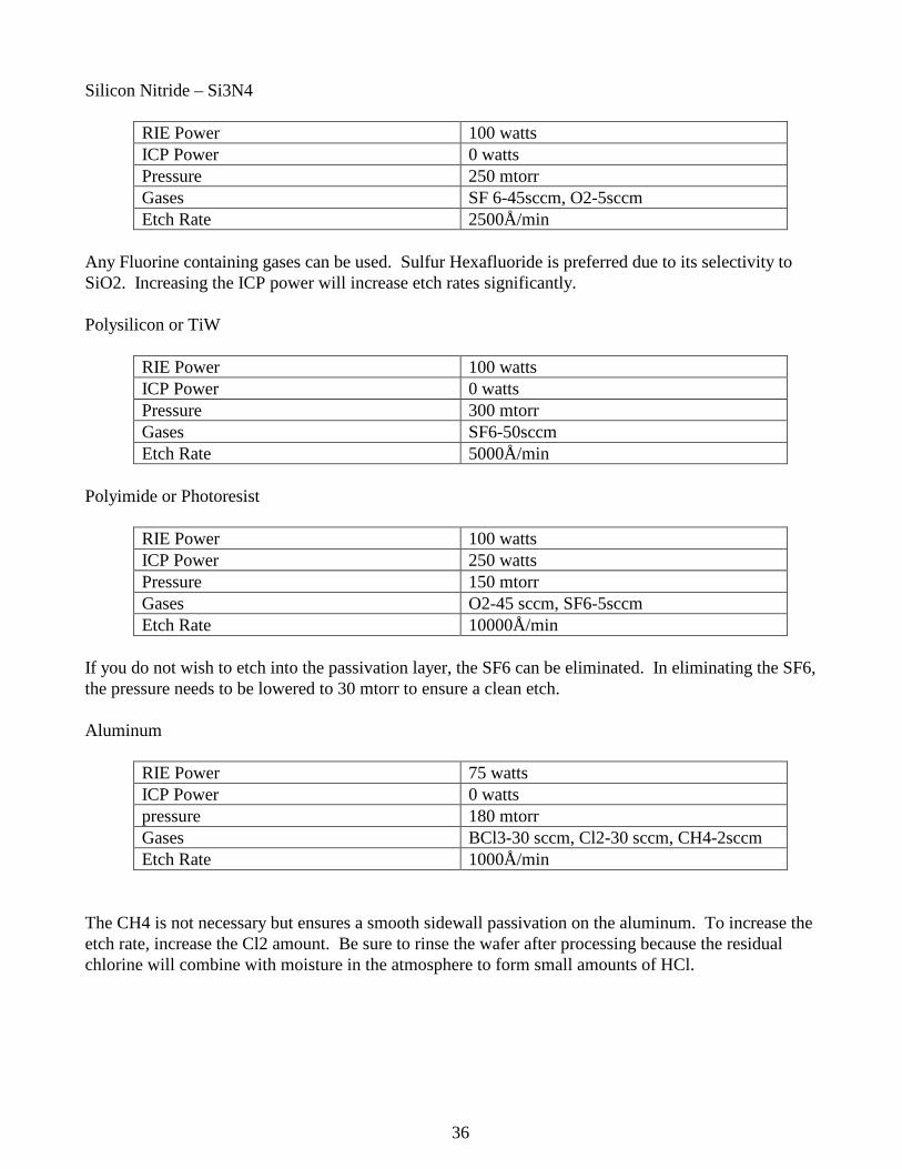
Silicon Nitride – Si3N4
RIE Power 100 watts ICP Power 0 watts Pressure 250 mtorr Gases SF 6-45sccm, O2-5sccm Etch Rate 2500Å/min
Any Fluorine containing gases can be used. Sulfur Hexafluoride is preferred due to its selectivity to SiO2. Increasing the ICP power will increase etch rates significantly. Polysilicon or TiW
RIE Power 100 watts ICP Power 0 watts Pressure 300 mtorr Gases SF6-50sccm Etch Rate 5000Å/min
Polyimide or Photoresist
RIE Power 100 watts ICP Power 250 watts Pressure 150 mtorr Gases O2-45 sccm, SF6-5sccm Etch Rate 10000Å/min
If you do not wish to etch into the passivation layer, the SF6 can be eliminated. In eliminating the SF6, the pressure needs to be lowered to 30 mtorr to ensure a clean etch. Aluminum
RIE Power 75 watts ICP Power 0 watts pressure 180 mtorr Gases BCl3-30 sccm, Cl2-30 sccm, CH4-2sccm Etch Rate 1000Å/min
The CH4 is not necessary but ensures a smooth sidewall passivation on the aluminum. To increase the etch rate, increase the Cl2 amount. Be sure to rinse the wafer after processing because the residual chlorine will combine with moisture in the atmosphere to form small amounts of HCl.

37
SYSTEM CLEANING
The RIE reactor should be cleaned every day by running the CLEAN recipe given above. The clean time should be at least 10 minutes. The chamber will occasionally need to be hand cleaned. This is performed as system maintenance as described below.
38
SYSTEM MAINTENANCE
GENERAL The Trion Apollo was designed in a highly modular form. There are seven fundamental modules: The AC Distribution Module The Process Control Module (Computer) The RF Generators The Reactor RIE Matching Network The Chamber Vacuum Pump The ICP Each of these modules has been designed for easy removal. This design concept eliminates the necessity of field repair work on the component level. MODULE REMOVAL If a module has become faulty or damaged it can easily be exchanged with a new one. However, the following modules should only be removed and replaced by trained TRION TECHNOLOGY personnel: ICP RIE Matching Network Process Controller All other modules can be removed by any trained maintenance personnel on site and replaced with new or loaner units from Trion Technology. The general procedure for removing any module is the following: Turn off the system power by pressing the EMO button on the front panel. Disconnect any cables to the module. Disconnect any water coolant hoses to the module and secure loose hoses so that they do not spill water over the equipment. Unplug the module’s power supply cord if applicable. Remove any mounting bolts from the system and slide the module out. For pumps, disconnect the inlet and outlet lines and use 2 people to lift or move a pump.
39
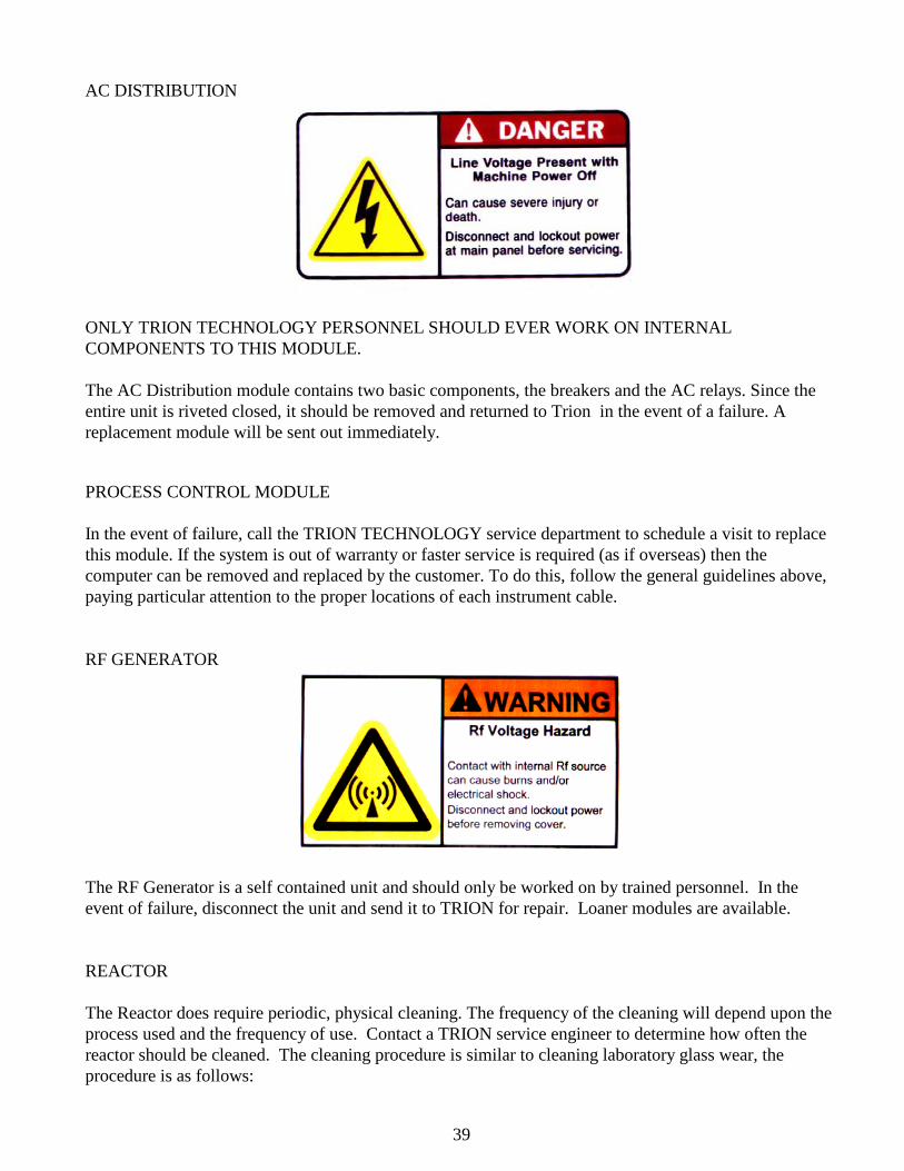
AC DISTRIBUTION
ONLY TRION TECHNOLOGY PERSONNEL SHOULD EVER WORK ON INTERNAL COMPONENTS TO THIS MODULE. The AC Distribution module contains two basic components, the breakers and the AC relays. Since the entire unit is riveted closed, it should be removed and returned to Trion in the event of a failure. A replacement module will be sent out immediately. PROCESS CONTROL MODULE In the event of failure, call the TRION TECHNOLOGY service department to schedule a visit to replace this module. If the system is out of warranty or faster service is required (as if overseas) then the computer can be removed and replaced by the customer. To do this, follow the general guidelines above, paying particular attention to the proper locations of each instrument cable. RF GENERATOR
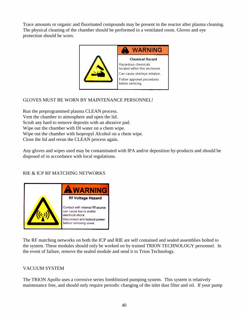
The RF Generator is a self contained unit and should only be worked on by trained personnel. In the event of failure, disconnect the unit and send it to TRION for repair. Loaner modules are available. REACTOR The Reactor does require periodic, physical cleaning. The frequency of the cleaning will depend upon the process used and the frequency of use. Contact a TRION service engineer to determine how often the reactor should be cleaned. The cleaning procedure is similar to cleaning laboratory glass wear, the procedure is as follows:
40
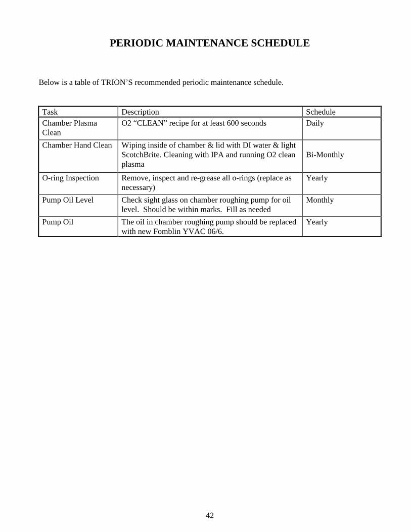
Trace amounts or organic and fluorinated compounds may be present in the reactor after plasma cleaning. The physical cleaning of the chamber should be performed in a ventilated room. Gloves and eye protection should be worn.
GLOVES MUST BE WORN BY MAINTENANCE PERSONNEL! Run the preprogrammed plasma CLEAN process. Vent the chamber to atmosphere and open the lid. Scrub any hard to remove deposits with an abrasive pad. Wipe out the chamber with DI water on a chem wipe. Wipe out the chamber with Isopropyl Alcohol on a chem wipe. Close the lid and rerun the CLEAN process again. Any gloves and wipes used may be contaminated with IPA and/or deposition by-products and should be disposed of in accordance with local regulations. RIE & ICP RF MATCHING NETWORKS
The RF matching networks on both the ICP and RIE are self contained and sealed assemblies bolted to the system. These modules should only be worked on by trained TRION TECHNOLOGY personnel. In the event of failure, remove the sealed module and send it to Trion Technology. VACUUM SYSTEM The TRION Apollo uses a corrosive series fomblinized pumping system. This system is relatively maintenance free, and should only require periodic changing of the inlet dust filter and oil. If your pump

41
was purchased from TRION TECHNOLOGY, reference the manufacturer’s vacuum pump manual contained in this manual. GLOVES MUST BE WORN WHEN FILLING OR CHANGING PUMP OIL! Gloves and any wipes that are used may be contaminated with Fomblin or Krytox pump oils and must be disposed off in accordance with local regulations.
42
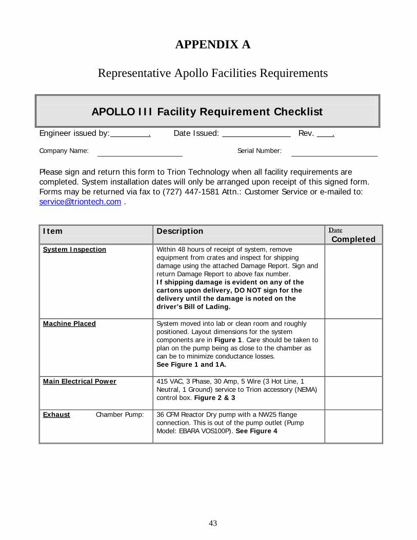
PERIODIC MAINTENANCE SCHEDULE Below is a table of TRION’S recommended periodic maintenance schedule. Task Description Schedule Chamber Plasma Clean
O2 “CLEAN” recipe for at least 600 seconds Daily
Chamber Hand Clean Wiping inside of chamber & lid with DI water & light ScotchBrite. Cleaning with IPA and running O2 clean plasma
Bi-Monthly
O-ring Inspection Remove, inspect and re-grease all o-rings (replace as necessary)
Yearly
Pump Oil Level Check sight glass on chamber roughing pump for oil level. Should be within marks. Fill as needed
Monthly
Pump Oil The oil in chamber roughing pump should be replaced with new Fomblin YVAC 06/6.
Yearly
43
APPENDIX A
Representative Apollo Facilities Requirements
APOLLO III Facility Requirement Checklist
Engineer issued by: . Date Issued: Rev. . Company Name: Serial Number: Please sign and return this form to Trion Technology when all facility requirements are completed. System installation dates will only be arranged upon receipt of this signed form. Forms may be returned via fax to (727) 447-1581 Attn.: Customer Service or e-mailed to: [email protected] . Item Description Date
Completed System Inspection Within 48 hours of receipt of system, remove
equipment from crates and inspect for shipping damage using the attached Damage Report. Sign and return Damage Report to above fax number. If shipping damage is evident on any of the cartons upon delivery, DO NOT sign for the delivery until the damage is noted on the driver’s Bill of Lading.
Machine Placed System moved into lab or clean room and roughly positioned. Layout dimensions for the system components are in Figure 1. Care should be taken to plan on the pump being as close to the chamber as can be to minimize conductance losses. See Figure 1 and 1A.
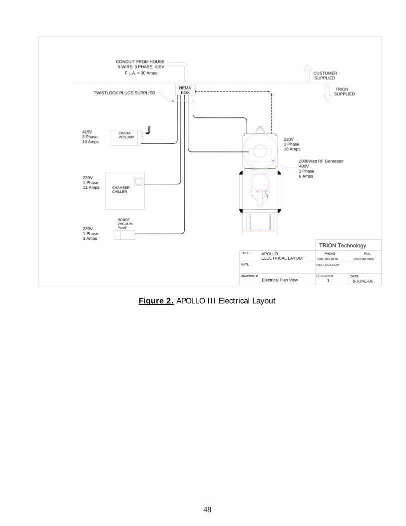
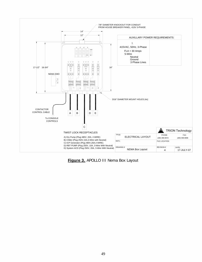
Main Electrical Power 415 VAC, 3 Phase, 30 Amp, 5 Wire (3 Hot Line, 1 Neutral, 1 Ground) service to Trion accessory (NEMA) control box. Figure 2 & 3
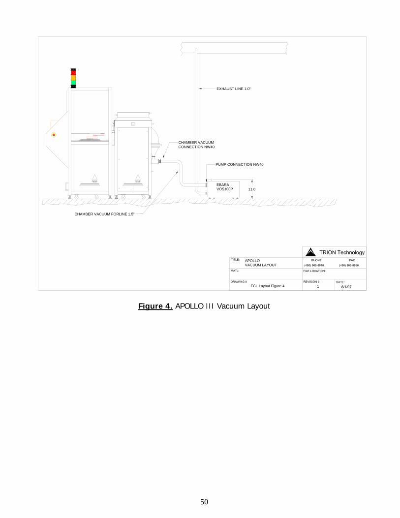
Exhaust Chamber Pump: 36 CFM Reactor Dry pump with a NW25 flange connection. This is out of the pump outlet (Pump Model: EBARA VOS100P). See Figure 4
44
Item Description Date Completed
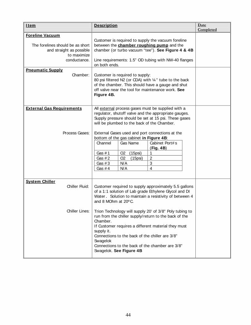
Foreline Vacuum The forelines should be as short
and straight as possible to maximize
conductance.
Customer is required to supply the vacuum foreline between the chamber roughing pump and the chamber (or turbo vacuum “tee”). See Figure 4 & 4B Line requirements: 1.5” OD tubing with NW-40 flanges on both ends.
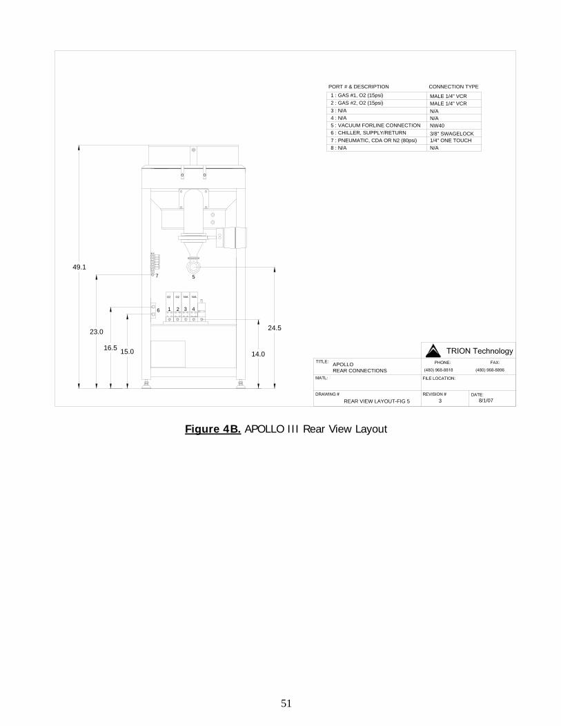
Pneumatic Supply Chamber:
Customer is required to supply: 80 psi filtered N2 (or CDA) with ¼” tube to the back of the chamber. This should have a gauge and shut off valve near the tool for maintenance work. See Figure 4B.
External Gas Requirements
Process Gases:
All external process gases must be supplied with a regulator, shutoff valve and the appropriate gauges. Supply pressure should be set at 15 psi. These gases will be plumbed to the back of the Chamber. External Gases used and port connections at the bottom of the gas cabinet in Figure 4B: Channel Gas Name Cabinet Port#s
(Fig. 4B) Gas #1 O2 (15psi) 1 Gas #2 O2 (15psi) 2 Gas #3 N/A 3 Gas #4 N/A 4
System Chiller Chiller Fluid:
Chiller Lines:
Customer required to supply approximately 5.5 gallons of a 1:1 solution of Lab grade Ethylene Glycol and DI Water. Solution to maintain a resistivity of between 4 and 8 MOhm at 20ºC. Trion Technology will supply 20’ of 3/8” Poly tubing to run from the chiller supply/return to the back of the Chamber. If Customer requires a different material they must supply it. Connections to the back of the chiller are 3/8” Swagelok Connections to the back of the chamber are 3/8” Swagelok. See Figure 4B
45
Item Description Date Completed
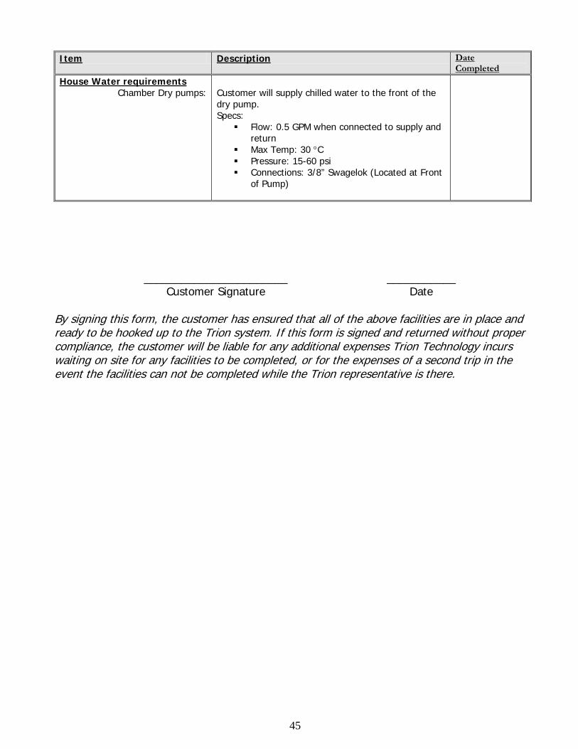
House Water requirements Chamber Dry pumps:
Customer will supply chilled water to the front of the dry pump. Specs:
Flow: 0.5 GPM when connected to supply and return
Max Temp: 30 °C Pressure: 15-60 psi Connections: 3/8” Swagelok (Located at Front
of Pump)
_______________________
Customer Signature ___________
Date By signing this form, the customer has ensured that all of the above facilities are in place and ready to be hooked up to the Trion system. If this form is signed and returned without proper compliance, the customer will be liable for any additional expenses Trion Technology incurs waiting on site for any facilities to be completed, or for the expenses of a second trip in the event the facilities can not be completed while the Trion representative is there.
46
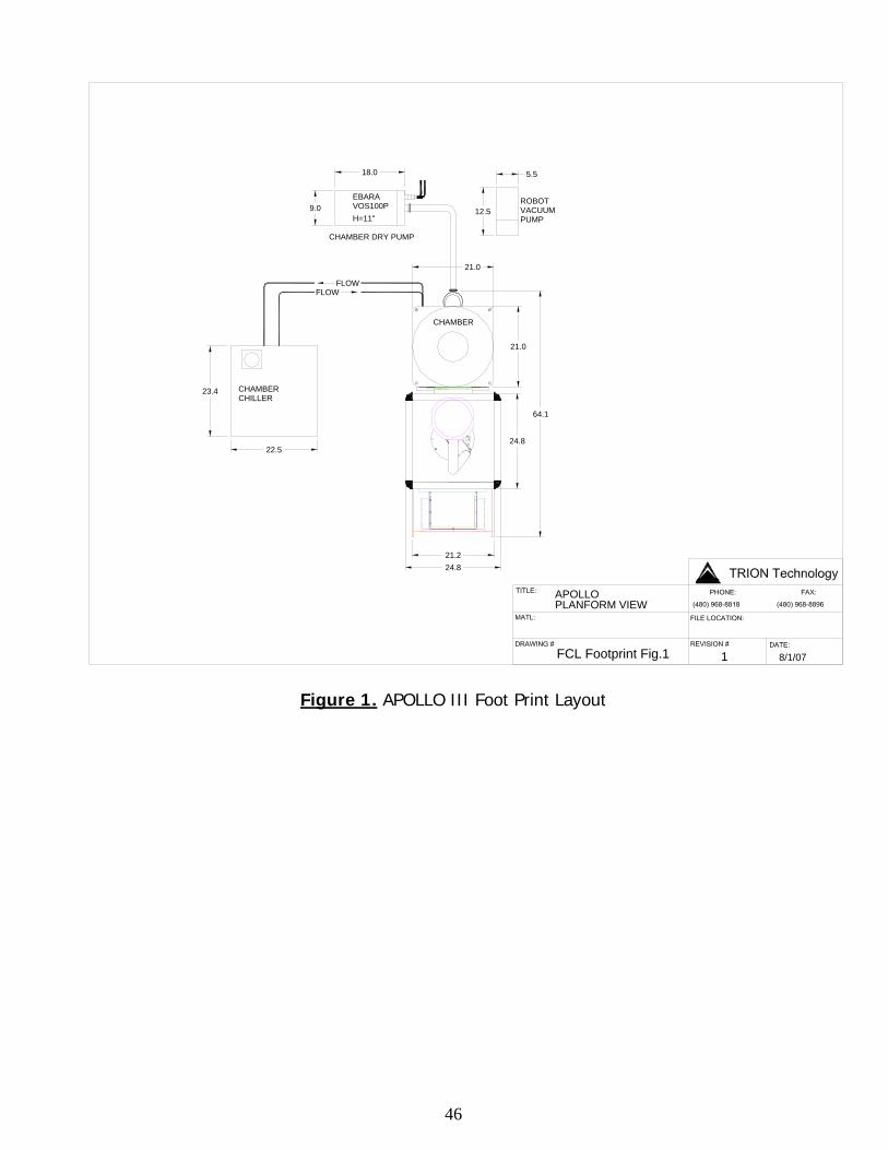
PLANFORM VIEW
FCL Footprint Fig.1 1 8/1/07
FLOWFLOW
EBARAVOS100PH=11"
9.0
18.0
CHAMBER DRY PUMP
APOLLO
CHAMBER
ROBOTVACUUMPUMP
5.5
12.5
23.4
22.5
CHAMBER CHILLER
21.0
21.0
24.8
64.1
24.821.2
Figure 1. APOLLO III Foot Print Layout
47
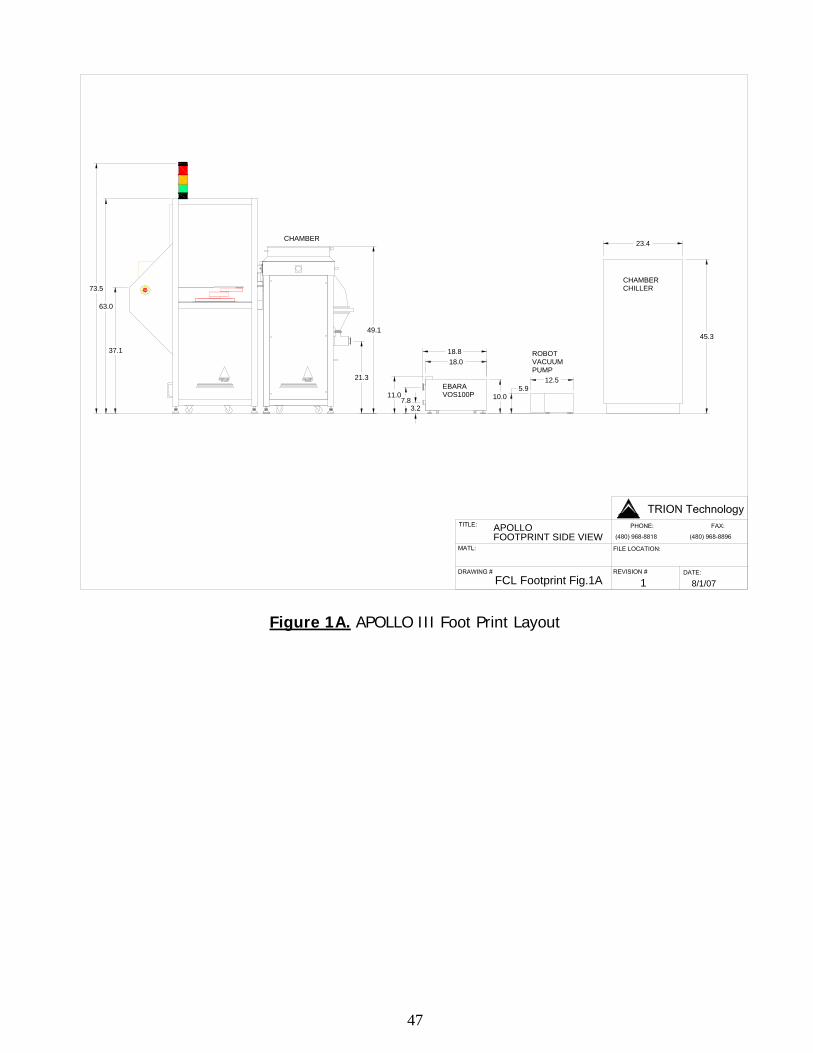
FOOTPRINT SIDE VIEW
FCL Footprint Fig.1A 1 8/1/07
APOLLO
PUMPVACUUMROBOT
EBARAVOS100P
CHAMBER CHILLER73.5
37.1
63.0
21.3
11.07.8
3.210.0
18.018.8
12.55.9
45.3
23.4CHAMBER
49.1
Figure 1A. APOLLO III Foot Print Layout
48
APOLLO
Electrical Plan View 1 8-JUNE-06
NEMABOX
415V3 Phase10 Amps
230V1 Phase11 Amps
230V1 Phase10 Amps
TWISTLOCK PLUGS SUPPLIED
CONDUIT FROM HOUSE5-WIRE, 3 PHASE, 415V
CUSTOMERSUPPLIED
TRIONSUPPLIED
F.L.A. = 30 Amps
EBARAVOS100P
ELECTRICAL LAYOUT
2000Watt RF Generator400V3 Phase6 Amps
CHILLERCHAMBER
PUMPVACUUMROBOT
3 Amps1 Phase230V
Figure 2. APOLLO III Electrical Layout
49
16"
N/C
NEMA EMO
17-1/2" 16-3/4"
3/16" DIAMETER MOUNT HOLES (4x)
C
D) System ACD (Plug 250V, 20A, 3-Wire With Neutral)
TWIST LOCK RECEPTACLES
A) Dry Pump (Plug 480V, 20A, 4 WIRE)B) Chiller (Plug 250V,15A,3-Wire with Neutral)C) ICP Generator (Plug 480V,20A,4 WIRE)D) RBT PUMP (Plug 250V, 10A, 3-Wire With Neutral)
CONTROLSTo CONSOLE
CONTROL CABLECONTACTOR
BA D E
G NG
NG
G NG
17-JULY-07NEMA Box Layout 4
7/8" DIAMETER KNOCKOUT FOR CONDUITFROM HOUSE BREAKER PANEL, 415V 3-PHASE
14"
L2
415VAC
L1 K1L3L2 L1 K2L2 L3 L1
CB1 CB2
415VAC
10A
240Vac
15A
L3K3L3 L1 L2 K4
CB4CB3 CB5
240Vac
10A10A
240Vac
20A
L1 L2 L3 L1L1
L1 L2 L3
L2L2 L3 L3
GND
N
12"
I.
5-WireNeutralGround
3 Phase Lines
FLA = 30 Amps415VAC, 50Hz, 3-Phase
AUXILLARY POWER REQUIREMENTS:
ELECTRICAL LAYOUT
Figure 3. APOLLO III Nema Box Layout
50
CHAMBER VACUUM FORLINE 1.5"
8/1/071
APOLLO
FCL Layout Figure 4
VACUUM LAYOUT
EBARAVOS100P
EXHAUST LINE 1.0"
CHAMBER VACUUM CONNECTION NW40
PUMP CONNECTION NW40
11.0
Figure 4. APOLLO III Vacuum Layout
51
O2 N/AO2
1 2 3 4
N/A
APOLLOREAR CONNECTIONS
REAR VIEW LAYOUT-FIG 5 3 8/1/07
B A
B A
15.016.5
23.0
14.0
24.5
5
6
7
1/4" ONE TOUCH
NW403/8" SWAGELOCK
N/AN/AMALE 1/4" VCRMALE 1/4" VCR
PORT # & DESCRIPTION CONNECTION TYPE1 : GAS #1, O2 (15psi)2 : GAS #2, O2 (15psi)3 : N/A4 : N/A5 : VACUUM FORLINE CONNECTION6 : CHILLER, SUPPLY/RETURN 7 : PNEUMATIC, CDA OR N2 (80psi)8 : N/A N/A
49.1
Figure 4B. APOLLO III Rear View Layout

52
Revision History 1.0 Original Document 2.0 Added details on LOT ID database interfacing usage.