Embed Size (px)
Citation preview
Rev: 03.17.2014 LCI Motorized Leveling (2009 - Present) Owner's Manual
LCI Motorized Leveling (2009 - Present)
Page 1
OWNER'S MANUAL
Rev: 03.17.2014 LCI Motorized Leveling (2009 - Present) Owner's ManualPage 2
TABLE OF CONTENTSSYSTEM 3
Prior to Operation 3System Description 3Features 4Fluid Recommendation 4Component Description 4System Wiring Requirements 4Air and Auxiliary Features 5Air and Auxiliary Feature Configuration 5Miscellaneous 5Steel Jacks 6Aluminum Jacks 7Control Panel 8Power Unit Components 9
OPERATION 10Selecting a Site 10Level Zero Point Calibration 10Automatic Leveling Procedure 11Manual Leveling Procedures 11Jack Retract Procedures 12
TROUBLESHOOTING 12Automatic Safety Shutoff 12Drive Away Protection System 12Error Mode 12Manual Override - Jacks 13Manual Override - Power System 13“Jacks Down" Alarm 14User Alarm Mode 14Low Voltage Signal 14Preventative Maintenance Procedures 15Latched Out Warning 15Troubleshooting Chart 16
PLUMBING DIAGRAM 17WIRING DIAGRAMS 18
Rev: 03.17.2014 LCI Motorized Leveling (2009 - Present) Owner's ManualPage 3
System
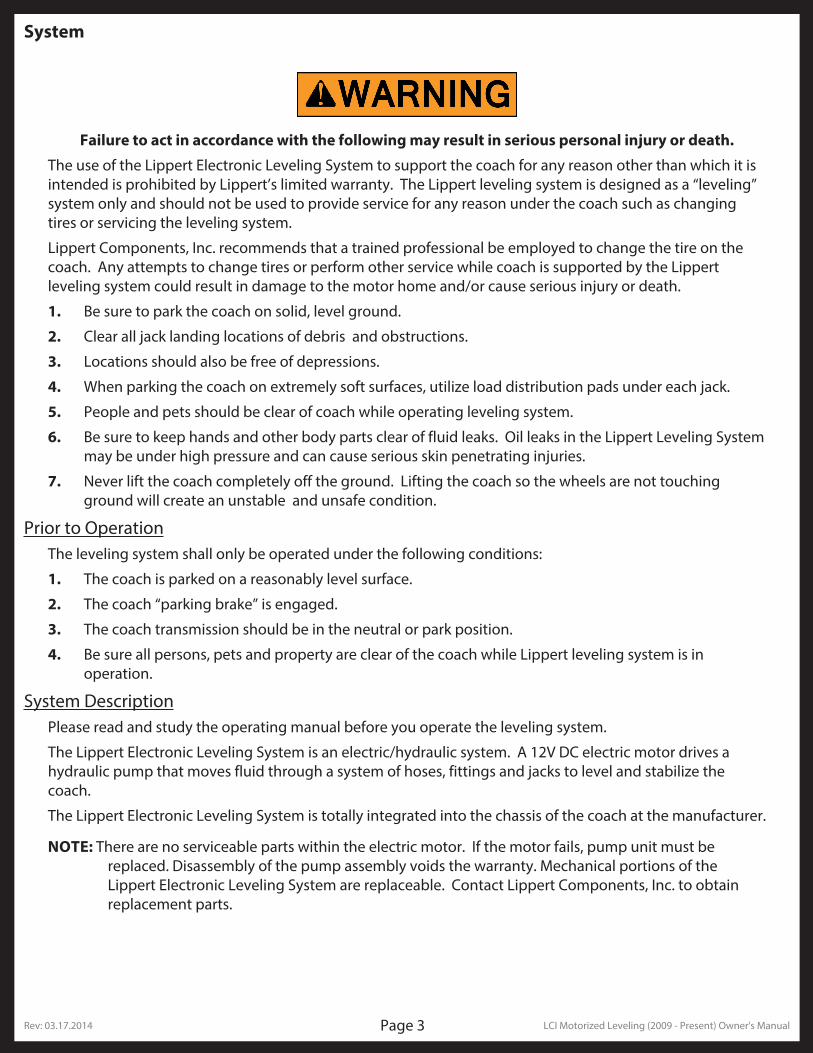
Failure to act in accordance with the following may result in serious personal injury or death.
The use of the Lippert Electronic Leveling System to support the coach for any reason other than which it is intended is prohibited by Lippert’s limited warranty. The Lippert leveling system is designed as a “leveling” system only and should not be used to provide service for any reason under the coach such as changing tires or servicing the leveling system.
Lippert Components, Inc. recommends that a trained professional be employed to change the tire on the coach. Any attempts to change tires or perform other service while coach is supported by the Lippert leveling system could result in damage to the motor home and/or cause serious injury or death.
1. Be sure to park the coach on solid, level ground.
2. Clear all jack landing locations of debris and obstructions.
3. Locations should also be free of depressions.
4. When parking the coach on extremely soft surfaces, utilize load distribution pads under each jack.
5. People and pets should be clear of coach while operating leveling system.
6. Be sure to keep hands and other body parts clear of fluid leaks. Oil leaks in the Lippert Leveling System may be under high pressure and can cause serious skin penetrating injuries.
7. Never lift the coach completely off the ground. Lifting the coach so the wheels are not touching ground will create an unstable and unsafe condition.
Prior to OperationThe leveling system shall only be operated under the following conditions:
1. The coach is parked on a reasonably level surface.
2. The coach “parking brake” is engaged.
3. The coach transmission should be in the neutral or park position.
4. Be sure all persons, pets and property are clear of the coach while Lippert leveling system is in operation.
System DescriptionPlease read and study the operating manual before you operate the leveling system.
The Lippert Electronic Leveling System is an electric/hydraulic system. A 12V DC electric motor drives a hydraulic pump that moves fluid through a system of hoses, fittings and jacks to level and stabilize the coach.
The Lippert Electronic Leveling System is totally integrated into the chassis of the coach at the manufacturer.
NOTE: There are no serviceable parts within the electric motor. If the motor fails, pump unit must be replaced. Disassembly of the pump assembly voids the warranty. Mechanical portions of the Lippert Electronic Leveling System are replaceable. Contact Lippert Components, Inc. to obtain replacement parts.
Rev: 03.17.2014 LCI Motorized Leveling (2009 - Present) Owner's ManualPage 4
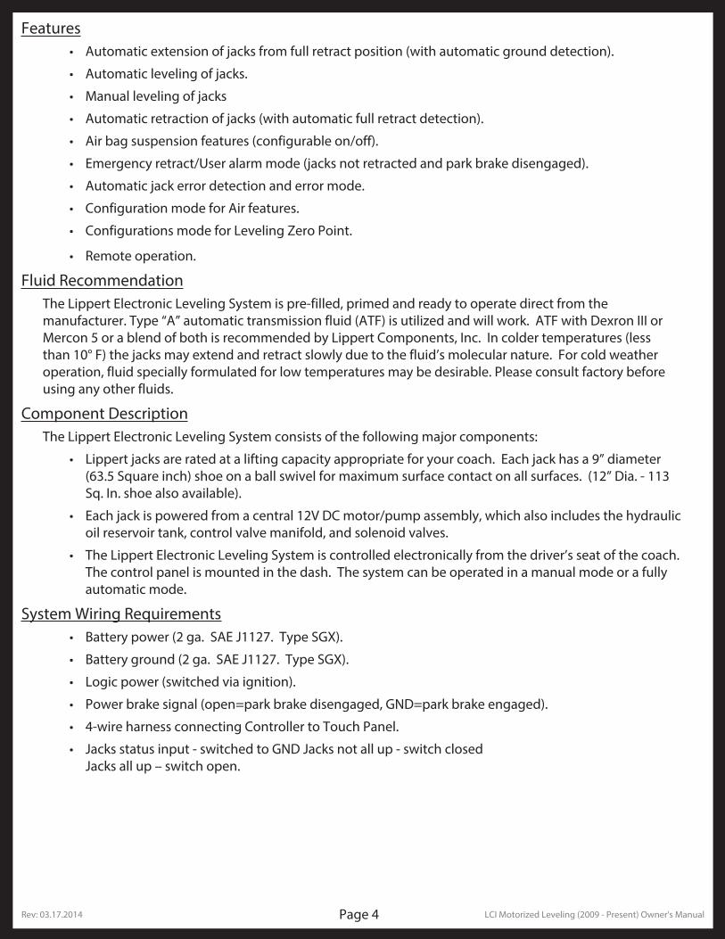
Features• Automatic extension of jacks from full retract position (with automatic ground detection).
• Automatic leveling of jacks.
• Manual leveling of jacks
• Automatic retraction of jacks (with automatic full retract detection).
• Air bag suspension features (configurable on/off).
• Emergency retract/User alarm mode (jacks not retracted and park brake disengaged).
• Automatic jack error detection and error mode.
• Configuration mode for Air features.
• Configurations mode for Leveling Zero Point.
• Remote operation.
Fluid RecommendationThe Lippert Electronic Leveling System is pre-filled, primed and ready to operate direct from the manufacturer. Type “A” automatic transmission fluid (ATF) is utilized and will work. ATF with Dexron III or Mercon 5 or a blend of both is recommended by Lippert Components, Inc. In colder temperatures (less than 10° F) the jacks may extend and retract slowly due to the fluid’s molecular nature. For cold weather operation, fluid specially formulated for low temperatures may be desirable. Please consult factory before using any other fluids.
Component DescriptionThe Lippert Electronic Leveling System consists of the following major components:
• Lippert jacks are rated at a lifting capacity appropriate for your coach. Each jack has a 9” diameter (63.5 Square inch) shoe on a ball swivel for maximum surface contact on all surfaces. (12” Dia. - 113 Sq. In. shoe also available).
• Each jack is powered from a central 12V DC motor/pump assembly, which also includes the hydraulic oil reservoir tank, control valve manifold, and solenoid valves.
• The Lippert Electronic Leveling System is controlled electronically from the driver’s seat of the coach. The control panel is mounted in the dash. The system can be operated in a manual mode or a fully automatic mode.
System Wiring Requirements• Battery power (2 ga. SAE J1127. Type SGX).
• Battery ground (2 ga. SAE J1127. Type SGX).
• Logic power (switched via ignition).
• Power brake signal (open=park brake disengaged, GND=park brake engaged).
• 4-wire harness connecting Controller to Touch Panel.
• Jacks status input - switched to GND Jacks not all up - switch closed Jacks all up – switch open.
Rev: 03.17.2014 LCI Motorized Leveling (2009 - Present) Owner's ManualPage 5
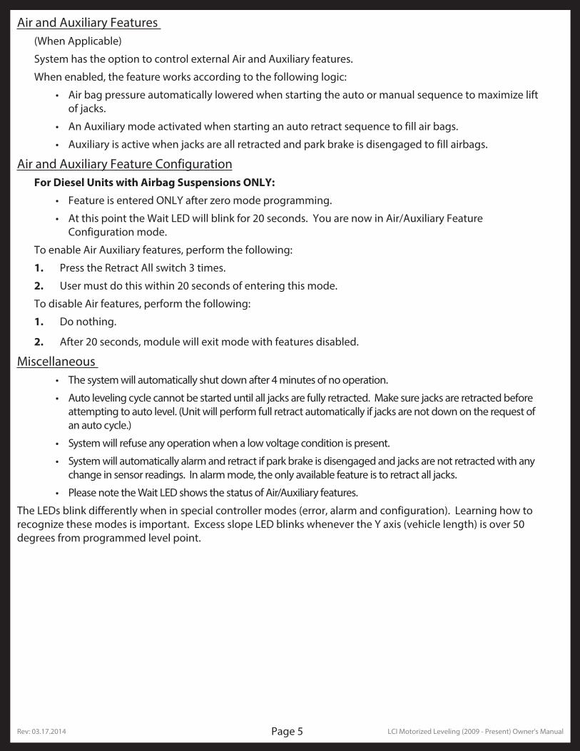
Air and Auxiliary Features (When Applicable)
System has the option to control external Air and Auxiliary features.
When enabled, the feature works according to the following logic:
• Air bag pressure automatically lowered when starting the auto or manual sequence to maximize lift of jacks.
• An Auxiliary mode activated when starting an auto retract sequence to fill air bags.
• Auxiliary is active when jacks are all retracted and park brake is disengaged to fill airbags.
Air and Auxiliary Feature ConfigurationFor Diesel Units with Airbag Suspensions ONLY:
• Feature is entered ONLY after zero mode programming.
• At this point the Wait LED will blink for 20 seconds. You are now in Air/Auxiliary Feature Configuration mode.
To enable Air Auxiliary features, perform the following:
1. Press the Retract All switch 3 times.
2. User must do this within 20 seconds of entering this mode.
To disable Air features, perform the following:
1. Do nothing.
2. After 20 seconds, module will exit mode with features disabled.
Miscellaneous • The system will automatically shut down after 4 minutes of no operation.
• Auto leveling cycle cannot be started until all jacks are fully retracted. Make sure jacks are retracted before attempting to auto level. (Unit will perform full retract automatically if jacks are not down on the request of an auto cycle.)
• System will refuse any operation when a low voltage condition is present.
• System will automatically alarm and retract if park brake is disengaged and jacks are not retracted with any change in sensor readings. In alarm mode, the only available feature is to retract all jacks.
• Please note the Wait LED shows the status of Air/Auxiliary features.
The LEDs blink differently when in special controller modes (error, alarm and configuration). Learning how to recognize these modes is important. Excess slope LED blinks whenever the Y axis (vehicle length) is over 50 degrees from programmed level point.
Rev: 03.17.2014 LCI Motorized Leveling (2009 - Present) Owner's ManualPage 6
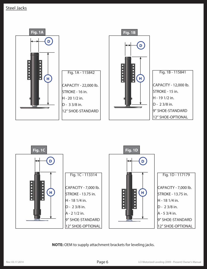
Fig. 1A Fig. 1B
Fig. 1C Fig. 1D
Fig. 1A - 115842
CAPACITY - 22,000 lb.
STROKE - 16 in.
H - 20 1/2 in.
D - 3 3/8 in.
12” SHOE-STANDARD
Fig. 1B - 115841
CAPACITY - 12,000 lb.
STROKE - 15 in.
H - 19 1/2 in.
D - 2 3/8 in.
9” SHOE-STANDARD
12” SHOE-OPTIONAL
Fig. 1C - 113314
CAPACITY - 7,000 lb.
STROKE - 13.75 in.
H - 18 1/4 in.
D - 2 3/8 in.
A - 2 1/2 in.
9” SHOE-STANDARD
12” SHOE-OPTIONAL
Fig. 1D - 117179
CAPACITY - 7,000 lb.
STROKE - 13.75 in.
H - 18 1/4 in.
D - 2 3/8 in.
A - 5 3/4 in.
9” SHOE-STANDARD
12” SHOE-OPTIONAL
NOTE: OEM to supply attachment brackets for leveling jacks.
Steel Jacks
D
H H
DD
D
H H
Rev: 03.17.2014 LCI Motorized Leveling (2009 - Present) Owner's ManualPage 7
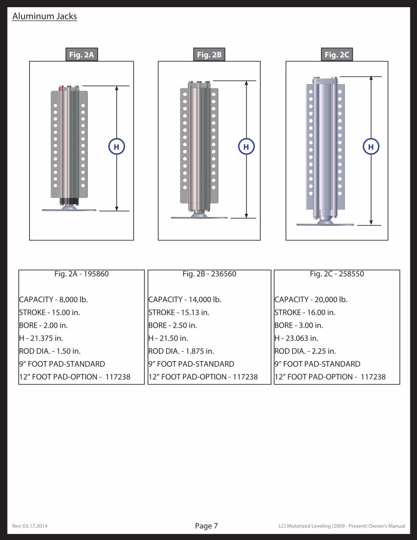
Aluminum Jacks
Fig. 2A - 195860
CAPACITY - 8,000 lb.
STROKE - 15.00 in.
BORE - 2.00 in.
H - 21.375 in.
ROD DIA. - 1.50 in.
9” FOOT PAD-STANDARD
12” FOOT PAD-OPTION - 117238
Fig. 2A Fig. 2B Fig. 2C
Fig. 2B - 236560
CAPACITY - 14,000 lb.
STROKE - 15.13 in.
BORE - 2.50 in.
H - 21.50 in.
ROD DIA. - 1.875 in.
9” FOOT PAD-STANDARD
12” FOOT PAD-OPTION - 117238
Fig. 2C - 258550
CAPACITY - 20,000 lb.
STROKE - 16.00 in.
BORE - 3.00 in.
H - 23.063 in.
ROD DIA. - 2.25 in.
9” FOOT PAD-STANDARD
12” FOOT PAD-OPTION - 117238
H H H
Rev: 03.17.2014 LCI Motorized Leveling (2009 - Present) Owner's ManualPage 8
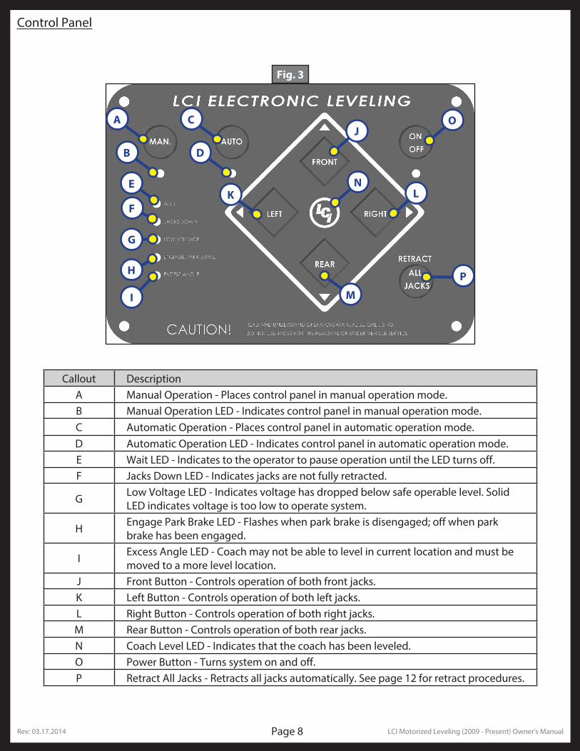
Fig. 3
A CJ
O
LK
M
P
E
F
G
I
H
N
B D
Callout DescriptionA Manual Operation - Places control panel in manual operation mode.B Manual Operation LED - Indicates control panel in manual operation mode.C Automatic Operation - Places control panel in automatic operation mode.D Automatic Operation LED - Indicates control panel in automatic operation mode.E Wait LED - Indicates to the operator to pause operation until the LED turns off. F Jacks Down LED - Indicates jacks are not fully retracted.
G Low Voltage LED - Indicates voltage has dropped below safe operable level. Solid LED indicates voltage is too low to operate system.
H Engage Park Brake LED - Flashes when park brake is disengaged; off when park brake has been engaged.
I Excess Angle LED - Coach may not be able to level in current location and must be moved to a more level location.
J Front Button - Controls operation of both front jacks.K Left Button - Controls operation of both left jacks.L Right Button - Controls operation of both right jacks.M Rear Button - Controls operation of both rear jacks.N Coach Level LED - Indicates that the coach has been leveled.O Power Button - Turns system on and off.P Retract All Jacks - Retracts all jacks automatically. See page 12 for retract procedures.
Control Panel
Rev: 03.17.2014 LCI Motorized Leveling (2009 - Present) Owner's ManualPage 9
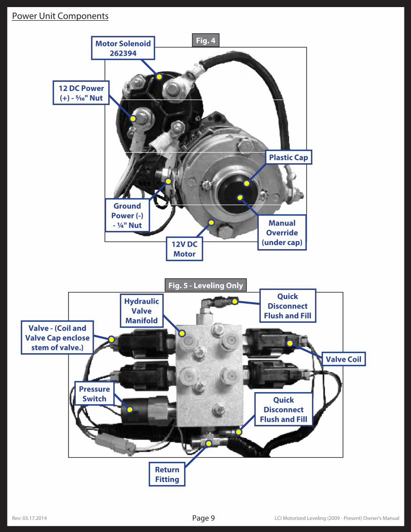
Power Unit Components
Motor Solenoid 262394
Fig. 4
12 DC Power (+) - 5/16" Nut
Ground Power (-) - 1/4" Nut
Plastic Cap
Manual Override
(under cap)12V DC Motor
Fig. 5 - Leveling Only
Hydraulic Valve
Manifold
Quick Disconnect
Flush and Fill
Valve Coil
Quick Disconnect
Flush and Fill
Pressure Switch
Valve - (Coil and Valve Cap enclose
stem of valve.)
Return Fitting
Rev: 03.17.2014 LCI Motorized Leveling (2009 - Present) Owner's ManualPage 10
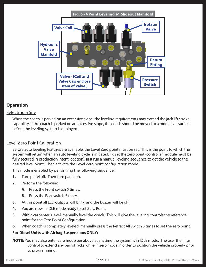
Fig. 6 - 4 Point Leveling +1 Slideout Manifold
Hydraulic Valve
Manifold
Pressure Switch
Valve - (Coil and Valve Cap enclose
stem of valve.)
Valve Coil
Return Fitting
Isolator Valve
OperationSelecting a Site
When the coach is parked on an excessive slope, the leveling requirements may exceed the jack lift stroke capability. If the coach is parked on an excessive slope, the coach should be moved to a more level surface before the leveling system is deployed.
Level Zero Point CalibrationBefore auto leveling features are available, the Level Zero point must be set. This is the point to which the system will return when an auto leveling cycle is initiated. To set the zero point (controller module must be fully secured in production intent location), first run a manual leveling sequence to get the vehicle to the desired level point. Then activate the Level Zero point configuration mode.
This mode is enabled by performing the following sequence:
1. Turn panel off. Then turn panel on.
2. Perform the following:
A. Press the Front switch 5 times.
B. Press the Rear switch 5 times.
3. At this point all LED outputs will blink, and the buzzer will be off.
4. You are now in IDLE mode ready to set Zero Point.
5. With a carpenter’s level, manually level the coach. This will give the leveling controls the reference point for the Zero Point Configuration.
6. When coach is completely leveled, manually press the Retract All switch 3 times to set the zero point.
For Diesel Units with Airbag Suspensions ONLY:
NOTE: You may also enter zero mode per above at anytime the system is in IDLE mode. The user then has control to extend any pair of jacks while in zero mode in order to position the vehicle properly prior to programming.
Rev: 03.17.2014 LCI Motorized Leveling (2009 - Present) Owner's ManualPage 11
Automatic Leveling Procedure
NOTE: Refer to Fig. 3 for questions regarding location and functions of the Lippert Components, Inc. Electronic Leveling System.
NOTE: Coach must be running and parking brake must be engaged for LCI Electronic Leveling System to operate.
1. Push ON/OFF button on Control Panel. The system is now operational and the electronic level lights will become active.
2. Check to see that the Control Pad ENGAGE PARK BRAKE light is not flashing.
3. Push the AUTO button to begin the automatic leveling cycle.
NOTE: After starting the automatic leveling cycle it is very important that you do not move around in the coach until the unit is level and the green LCI logo light illuminates in the center of the touchpad. Failure to remain still during the leveling cycle could have an affect on the performance of the leveling system.
4. If further adjustments are necessary, refer to the Manual Leveling Procedures section below.
Lifting all wheels of the ground may result in serious personal injury or death.
5. Push power button to turn off the system.
Manual Leveling Procedures
NOTE: When leveling your coach, the coach should be leveled from front to rear first (Step 2-4). When the coach is level from front to rear, then level the coach from left to right (Step 5).
NOTE: Coach must be running for LCI Electronic Leveling System to operate.
1. Push ON/OFF button on control panel. The system is now operational and the ON/OFF light will be lit.
2. Push and hold MAN button for 5 seconds.
3. Push FRONT button until jacks contact the ground and lift the front of the coach 1-2 inches.
4. Push REAR button until jacks contact the ground and lift rear of coach. Keep button depressed until bubble is centered.
5. Push LEFT or RIGHT button; if bubble is towards left of coach, push RIGHT button; if bubble is towards right of coach push LEFT button. Keep button depressed until bubble is centered in vial.
NOTE: The right and left jacks are used to level the coach side to side. Pushing the LEFT button on the control panel will extend both left jacks. Pushing the RIGHT button on the control panel will extend both right jacks. Jacks always work in pairs, both front jacks; both right side jacks, etc.
6. Repeat steps 2 through 5 if needed.
7. Turn power off to leveling system by pushing ON/OFF button.
8. Visually inspect all jacks to ensure all shoes are touching ground. Should one of the rear jack shoes not be touching the ground, press the corresponding LEFT or RIGHT rear jack buttons to lower the corresponding jack to the ground.
Lifting all wheels of the ground may result in serious personal injury or death.
Rev: 03.17.2014 LCI Motorized Leveling (2009 - Present) Owner's ManualPage 12
Jack Retract Procedures1. Energize the system by pushing ON/OFF button on control panel. The ON/OFF light will be lit.
2. Push the RETRACT ALL JACKS button. All the jacks will start to retract and return to the full retract position. When all jacks return to full retract position the JACKS DOWN light will go out.
NOTE: If you wish to stop the jacks from retracting, turn the system off and back on again by pushing the ON/OFF button twice. You can then re-level the coach by following steps 1-5 again.
3. When the JACKS DOWN light goes out, push the ON/OFF button on the Control Panel to de-energize the system. After a brief visual inspection around the coach to verify the jacks are fully retracted, you may proceed to travel.
NOTE: When in the MANUAL mode, if the RETRACT button is pushed the jacks will only retract as long as the RETRACT button is depressed. In AUTOMATIC mode, the RETRACT button need only be pressed once and released for the jacks to fully retract.
TroubleshootingAutomatic Safety Shutoff
If the control panel is left on and inactive for four minutes it will shut off automatically. To reset the system the coach ignition must be turned off, then back on and the ON/OFF button must again be pushed.
Drive Away Protection SystemIf the ignition is in the “RUN” position, jacks are down, and the operator releases the parking brake, all indicator lights will flash and the alarm beeper will activate. The system will then automatically retract the jacks until the jacks are fully retracted or the operator resets the parking brake.
The power unit will also operate to keep the jacks retracted in the event the leveling system loses pressure as the coach is being driven.
Error ModeIf any problem is detected with the jacks, the system will enter Error Mode. Error mode may be recognized by the blinking of Left, Center LCI and Right LEDs.
The following errors are detected by this system:
• Jack over current/short circuit.
• Jack under current/ open circuit.
• Jack extending too long (ground not detected after 2 min.).
• Jack retracting too long (fully retracted not detected after 2 min.).
• Out of stroke detection during auto cycle (if enabled).
The user must respond by pressing On/Off switch, which resets operation.
All normal features are disabled in Error Mode.
If panel loses communication with the controller for more than 5 seconds, the panel will blink the Jacks Down, Park Brake and ON/OFF (if included) LEDs.
Rev: 03.17.2014 LCI Motorized Leveling (2009 - Present) Owner's ManualPage 13
Fig. 7A Fig. 7B
Clockwise for manual override Counter-clockwise for normal operation
Fig. 8 Fig. 9
Plastic Cap
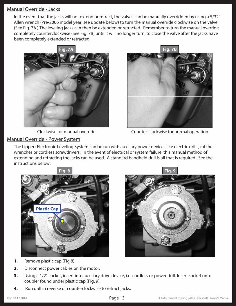
Manual Override - JacksIn the event that the jacks will not extend or retract, the valves can be manually overridden by using a 5/32” Allen wrench (Pre-2006 model year, see update below) to turn the manual override clockwise on the valve. (See Fig. 7A.) The leveling jacks can then be extended or retracted. Remember to turn the manual override completely counterclockwise (See Fig. 7B) until it will no longer turn, to close the valve after the jacks have been completely extended or retracted.
Manual Override - Power SystemThe Lippert Electronic Leveling System can be run with auxiliary power devices like electric drills, ratchet wrenches or cordless screwdrivers. In the event of electrical or system failure, this manual method of extending and retracting the jacks can be used. A standard handheld drill is all that is required. See the instructions below.
1. Remove plastic cap (Fig 8).
2. Disconnect power cables on the motor.
3. Using a 1/2” socket, insert into auxiliary drive device, i.e. cordless or power drill. Insert socket onto coupler found under plastic cap (Fig. 9).
4. Run drill in reverse or counterclockwise to retract jacks.
Rev: 03.17.2014 LCI Motorized Leveling (2009 - Present) Owner's ManualPage 14
“Jacks Down" AlarmThe Lippert Electronic Leveling System is designed to sound an alarm and illuminate the control panel in the event of two (2) possible scenarios:
A. A “RETRACT” hose leaks.
B. The pressure holding the jacks in the retracted position falls to approximately 1500 psi to sound the alarm.
If the alarm sounds and the control panel illuminates and flash while driving the vehicle:
1. Immediately find an area to safely pull the vehicle off of the roadway.
2. Set the PARKING BRAKE.
3. Inspect all jacks hoses and check valve for leaks.
If no leaks are observed;
1. Turn control panel “ON.”
2. Push “RETRACT ALL JACKS” button.
3. Wait until “JACKS DOWN” light and alarm are off.
4. Inspect jacks. If jacks are retracted and no leaks are observed, vehicle can be driven.
If system is leaking or alarm does not subside after applying the above procedure, disconnect wires from pressure switch and proceed immediately to a service center. For prolonged travel to the service center, be sure to stop and check the disposition of the leveling jacks periodically to make sure they are not extending.
User Alarm ModeIf the alarm system detects that the park brake has been disengaged while at least one jack is not fully retracted and the sensor value changes in any axis more than a predefined amount, the panel will signal this error to the user.
When in alarm mode, all LEDs will flash and the buzzer will beep. The status LEDs will show the system status.
The system performs an automatic retract.
No other features are available in this mode.
Low Voltage SignalIf LOW VOLTAGE light is on solid, it is an indication of a charging system problem. Turn ignition OFF and then back ON to reset system. If LOW VOLTAGE light persists, test battery under load at battery and at the motor solenoid on the pump unit. Check all power and ground connections at the battery, alternator and chassis.
Rev: 03.17.2014 LCI Motorized Leveling (2009 - Present) Owner's ManualPage 15
Preventative Maintenance Procedures1. Change fluid in RESERVOIR ONLY when contaminated.
A. Check fluid only when jacks are fully retracted.
B. Always fill the reservoir with the jacks in the fully retracted position. Filling reservoir when jacks are extended will cause reservoir to overflow into its compartment when jacks are retracted.
C. When checking fluid level, fluid should be within ¼” of fill spout lip.
2. Check the fluid level every month.
3. Inspect and clean all Pump Unit electrical connections every 12 months. If corrosion is evident, spray unit with WD-40 or equivalent.
4. Remove dirt and road debris from jacks as needed.
Your coach should be supported at both front and rear axles with jack stands before working underneath. Failure to do so may result in personal injury or death.
5. If jacks are down for extended periods, it is recommended to spray exposed leveling jack rods with a silicone lubricant every three months for protection. If your coach is located in a salty environment, it is recommended to spray the rods every 4 to 6 weeks.
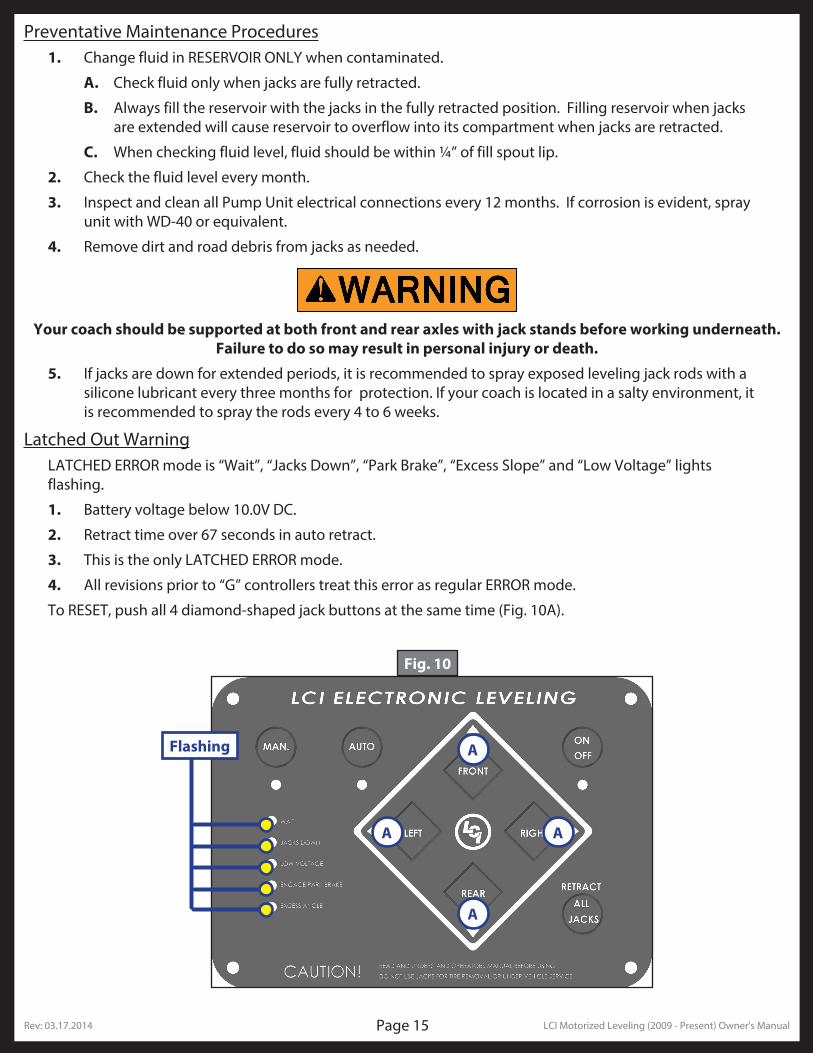
Latched Out WarningLATCHED ERROR mode is “Wait”, “Jacks Down”, “Park Brake”, “Excess Slope” and “Low Voltage” lights flashing.
1. Battery voltage below 10.0V DC.
2. Retract time over 67 seconds in auto retract.
3. This is the only LATCHED ERROR mode.
4. All revisions prior to “G” controllers treat this error as regular ERROR mode.
To RESET, push all 4 diamond-shaped jack buttons at the same time (Fig. 10A).
Fig. 10
A
A A
A
Flashing
Rev: 03.17.2014 LCI Motorized Leveling (2009 - Present) Owner's ManualPage 16
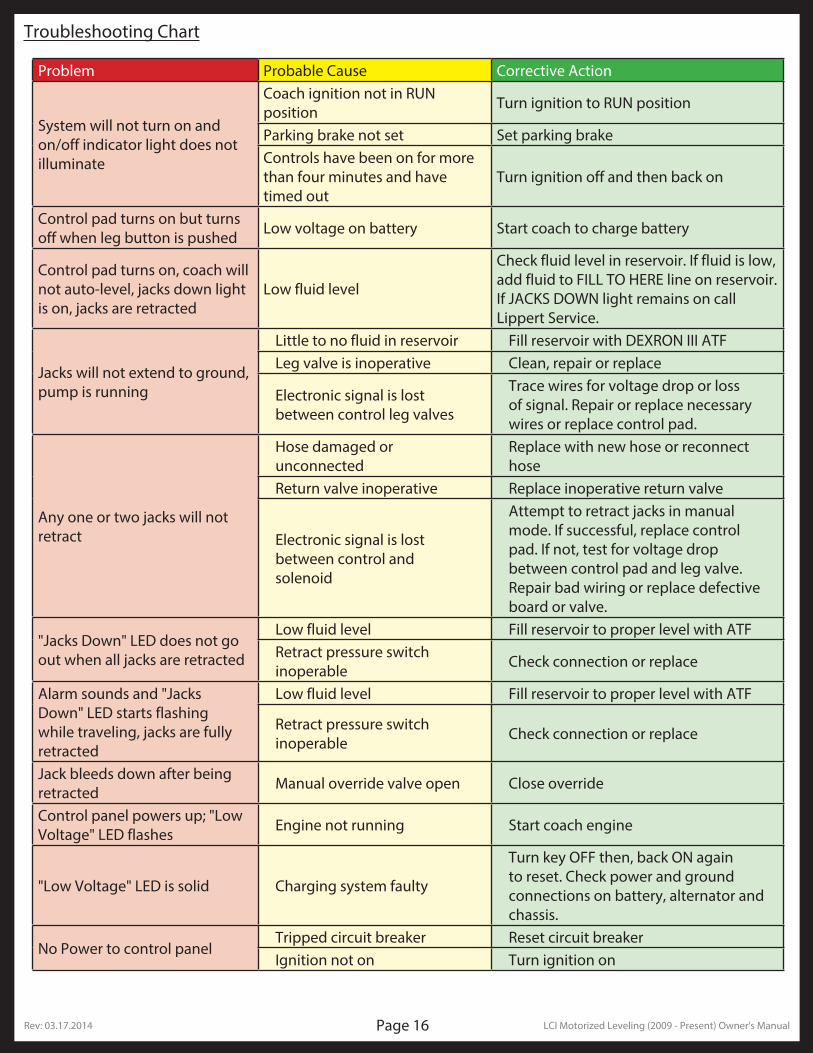
Troubleshooting Chart
Problem Probable Cause Corrective Action
System will not turn on and on/off indicator light does not illuminate
Coach ignition not in RUN position Turn ignition to RUN position
Parking brake not set Set parking brakeControls have been on for more than four minutes and have timed out
Turn ignition off and then back on
Control pad turns on but turns off when leg button is pushed Low voltage on battery Start coach to charge battery
Control pad turns on, coach will not auto-level, jacks down light is on, jacks are retracted
Low fluid level
Check fluid level in reservoir. If fluid is low, add fluid to FILL TO HERE line on reservoir. If JACKS DOWN light remains on call Lippert Service.
Jacks will not extend to ground, pump is running
Little to no fluid in reservoir Fill reservoir with DEXRON III ATFLeg valve is inoperative Clean, repair or replace
Electronic signal is lost between control leg valves
Trace wires for voltage drop or loss of signal. Repair or replace necessary wires or replace control pad.
Any one or two jacks will not retract
Hose damaged or unconnected
Replace with new hose or reconnect hose
Return valve inoperative Replace inoperative return valve
Electronic signal is lost between control and solenoid
Attempt to retract jacks in manual mode. If successful, replace control pad. If not, test for voltage drop between control pad and leg valve. Repair bad wiring or replace defective board or valve.
"Jacks Down" LED does not go out when all jacks are retracted
Low fluid level Fill reservoir to proper level with ATFRetract pressure switch inoperable Check connection or replace
Alarm sounds and "Jacks Down" LED starts flashing while traveling, jacks are fully retracted
Low fluid level Fill reservoir to proper level with ATF
Retract pressure switch inoperable Check connection or replace
Jack bleeds down after being retracted Manual override valve open Close override
Control panel powers up; "Low Voltage" LED flashes Engine not running Start coach engine
"Low Voltage" LED is solid Charging system faulty
Turn key OFF then, back ON again to reset. Check power and ground connections on battery, alternator and chassis.
No Power to control panelTripped circuit breaker Reset circuit breakerIgnition not on Turn ignition on
Rev: 03.17.2014 LCI Motorized Leveling (2009 - Present) Owner's ManualPage 17
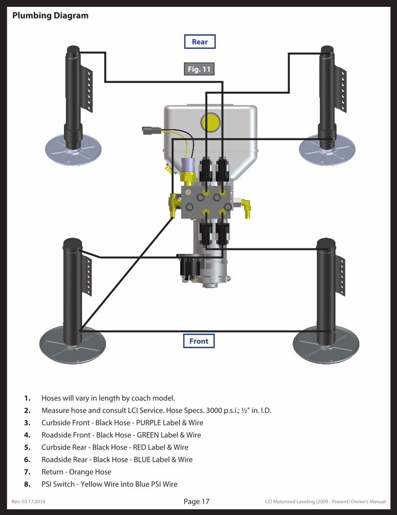
Plumbing Diagram
Fig. 11
Rear
Front
1. Hoses will vary in length by coach model.
2. Measure hose and consult LCI Service. Hose Specs. 3000 p.s.i.; ½” in. I.D.
3. Curbside Front - Black Hose - PURPLE Label & Wire
4. Roadside Front - Black Hose - GREEN Label & Wire
5. Curbside Rear - Black Hose - RED Label & Wire
6. Roadside Rear - Black Hose - BLUE Label & Wire
7. Return - Orange Hose
8. PSI Switch - Yellow Wire into Blue PSI Wire
Rev: 03.17.2014 LCI Motorized Leveling (2009 - Present) Owner's ManualPage 18
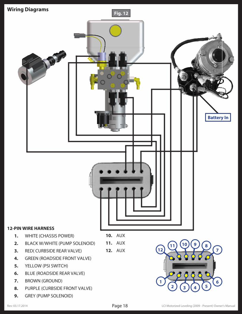
Wiring Diagrams
1211 10 9 8
7
12 3 4 5
6
12-PIN WIRE HARNESS
1. WHITE (CHASSIS POWER)
2. BLACK W/WHITE (PUMP SOLENOID)
3. RED( CURBSIDE REAR VALVE)
4. GREEN (ROADSIDE FRONT VALVE)
5. YELLOW (PSI SWITCH)
6. BLUE (ROADSIDE REAR VALVE)
7. BROWN (GROUND)
8. PURPLE (CURBSIDE FRONT VALVE)
9. GREY (PUMP SOLENOID)
10. AUX
11. AUX
12. AUX
Battery In
Fig. 12
Rev: 03.17.2014 LCI Motorized Leveling (2009 - Present) Owner's ManualPage 19
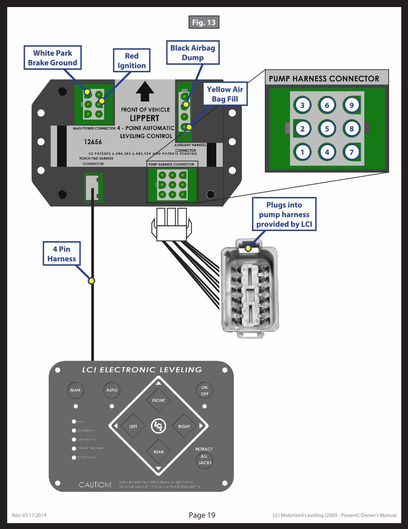
4 Pin Harness
White Park Brake Ground
Red Ignition
Black Airbag Dump
Plugs into pump harness
provided by LCI
Yellow Air Bag Fill
1
2
3 6 9
5 8
4 7
Fig. 13


![] 4§¿kU T À+ E CÄ Rc R ¨ò æ æ æ æ C P æ æ æ Rb æwP æx æ æ æ æ C æ Rbæ æ P æwP æx &r'A!Q->] ;f f3w%(]x( 1 W+ f3Jj° 0 ŧ ÅpwS§](https://img.pdfslide.net/doc/110x75/5ea63cf9fca6062015765e71/-4-ku-t-e-c-rc-r-c-p-rb-wp-x-.jpg)


![æ Y ^ æ X ä X ] Z Z æ ^ ^ æ [ a æ Z](https://img.pdfslide.net/doc/110x75/622c109c31a0050027169c57/-y-x-x-z-z-a-z.jpg)