Embed Size (px)
Citation preview

ELECTRICAL AND MECHANICAL ENGINEERING INSTRUCTIONS
TRUCK CARGO MEDIUM MC2
TRUCKCARGOMEDIUMWINCHMC2 BASE REPAIR
VEHICLE (2604-I Issue 1. Ott 84
Figure 1 Truck Three-quarter Front and Rear Views
i/ii
UN
CO
NT
RO
LLE
D W
HE
N P
RIN
TE
D
UN
CO
NT
RO
LLE
D W
HE
N P
RIN
TE
D

0 0
0
0
0
0 0
ELECTRICALANDMECHANICAL VEHICLE C604I ENGINEERING INSTRUCTIONS Issue 1, Ott 84
INTRODUCTION SPECIAL TOOLS ENGINE
Engine Repair Guide Rocker Shafts and Arms
Removal Installation
Camshaft Removal Installation
Pistons and Connecting Rods Removal Repair Installation
Crankshaft and Bearings Removal Repair Installation
Engine Tolerances TURBOCHARGER
Dismantling Inspection Assembly
MAIN TRANSMISSION Intermediate Housing - Rear
Removal Repair Installation
Intermedtate Housing - Front Removal Repair Installatron
Transfer Case Removal Repair Installation
Main Gearbox Epicyclic Gear Assembly Oil Pump Assembly Input Shaft Assembly Countershaft Mainshaft .4ssembly Reverse Idler Assembly Gear Selector ,Assembly
TABLEOFCONTENTS
Para No
I 6 7 8 9
10 I I I’ I3 I4 IS I6 I7 I8 I9 ‘0 ‘I 77 -- 23 74 ‘5 -- 26 27 28 29 30 31 32 33 34 35 36 37 38 39 40 41 42 13 44 45 36 -17 -18
. . . III
UN
CO
NT
RO
LLE
D W
HE
N P
RIN
TE
D
VEHICLE G604-1 Issue 1, Ott 84
PTO TRANSMISSION Clutch Bell Housing
Idler Gear Assembly Transfer Casing
Transfer Gear Assembly Auxiliary Gear Assembly
REAR AXLE Wheel Hubs and Half-shafts
Removal Repair Installation
Differential Removal Repair Adjustment Installation
FRONT AXLE Steering Knuckle Bearings
Removal Installation
Wheel Hubs and Halfshafts Differential
BRAKE SYSTEM Brake System Repair Guide Air Compressor
Dismantling Assembly
Tandem Master Cylinder Dismantling .4ssembly
Front Brake Calipers Dismantling Assembly
Rear Brake Calipers Dismantling Assembly
Four-circuit Protection Valve ~Boschl Dismantling ,4ssembly Testing
Trailer Brake Stretch Valve (Wabcol Dismantling Assembly Testing
Pneumatic Master Cylinder (Wabcol Dismantling Assembly Testing
ELECTRICAL AND MECHANICAL ENGINEERING INSTRUCTlONS
Para No
49 50 51 52 53 54 55 56 51 58 59 60 61 62 63 64 65 66 67 68 69 70 71 71 73 74 75 76 77 78 79 80 81 81 83 84 85 86 87 88 89 90 91 92 93 94 95 96
a l
0
l
a
iv
UN
CO
NT
RO
LLE
D W
HE
N P
RIN
TE
D

ELECTRICAL AND MECHANICAL ENGINEERING INSTRUCTIONS
VEHICLE C604-I Issue 1, Ott 84
0 0
0
Shift C..vlinder /Nabcot 97 Dismantlmg 98 Assembly 99 Testing 100
Handbrake Valve IWabcol I 0 I Dismantling IO’ Assembly IO! Testmg IO-1
Parking Brake Cyhnder (Wabco) I05 Dismantling 106 Assembly 107 Testing I08
ALB Valve (Wabcol 109 Dismantling I IO Assembly III Testing II’
Footbrake Valve (Wabco) 113 Dismantling I I4 Assembly II5 Testing I I6
Four-circuit Protection Valve (Wabco) II7 Dismantling II8 Assembly 119 Testmg I’0
Trailer Brake Control Valve IWabcot I’1 Dismantling 173 Assembly 123 Testing 124
Engine Brake Valve (Bosch) 125 Dismantlmg 126 Assembly I27 Testing 118
Pressure Limiting Valve, Brake Circuit IBosch) 129 Dismantling 130 Assembly 131 Testing I31
Dual-pressure Pressure Limiting Valve iBosch) I33 Dismantling 134 Assembly I35 Testing 136
Footbrake Valve tBosch) 137 Dismantling I38 Assembly 139 Testing 140
Pressure Regulator (Bosch) l-l1 Testing I42
Para NO
UN
CO
NT
RO
LLE
D W
HE
N P
RIN
TE
D
VEHICLE G604-1 Issue I, Ott 84
Handbrake Valve {Bosch) Testing
Engine Brake Cylinder Knorrl Dismantling Assembly Testing
Pressurisation and Venting Valve (Wabcol Assembly Instructions Testing
BODY Cab
Removal Installation
Cargo Tray Removal Installation
FUEL SYSTEM Fuel injection Pump .4ssembly
Manifold Pressure Compensator tMPCj Governor Injection Pump
Fuel Injectors Dismantling Assembly
WINCH Dismantling Assembly
ELECTRICAL AND MECHANICAL ENGINEERING INSTRUCTIONS
Para No
I52 I53 15-l I55 I56 I57 I58 159 160 I61 I63 I63 164 I65 I66 167 16s
l
0
l
a
l
l
a
vi
UN
CO
NT
RO
LLE
D W
HE
N P
RIN
TE
D

ELECTRICAL AND MECHANICAL ENGINEERING INSTRUCTIONS
0
0
l
0 l
VEHICLE G604.1 lssuc I. Ott 8-l
LIST OF FIGURES
I Truth Three-quarter Front and Rear VI<\\\
2 Spsc~al Tool> 3 Engrne - LH Side and Fronr Sec~~oneJ l’~tw\
1 C‘omprwlng the N~pplt: .\ssembl! 5 Rocher Shaft Nipple .Assembl!
6 Rocber Shaft .Assenibl) 7 Camshaft Tappet\ 8 Clamp 9 Removing the Drlw Gear and Timing .Aswiibl!
IO Camshaft Thrust Plate I OS Engine Performance Graph I I Main Seal Retaining Pin I3 Installarlon - Rear hlam Seal I3 Turbocharger Assembly 1-I Turbme Wheel Holding Fixture 15 Turbine Wheel In the Holding Fixture I6 Turbocharger Centre Houhinp - SectIoned Vie\+ I7 Mam Transmission Assembl! IS Spesdomerer Drive Spindle I9 Transfer Gears and Oil Baffle 20 Transfer Case Components 11 Bearing Shroud 27 Transfer Case End-cover Removal 23 Idler Gear and Shaft Removal 74 Idler Shaft Oil Channel ‘5 -- Removing the Selector Forh Spring Pin 26 Removal of’ Locking Pins 17 Epicyclic Gear Assembl!, 28 Planetary Gear Shafts Grub Screws 29 llleasurlng Play at Synchro Hub 30 Transmlsslon 011 Pump Assembly 31 Oil Pump Clamp and Retaining Bolt 32 Withdrawing the Oil Pump 33 End Cobers and Bearing Caps 34 Selector Rod Screw Plugs 35 Spring Pin 36 Removmg the Input Shaft Gearset 37 Input Shaft Assembl) 38 Selector Forh Measurement 39 MaInshaft Assembly 40 Remowng Istl5rh Gear dl Removing 2ndi6th Gear 42 Removing the Sun-gear 13 Reverse Idler Gear 4-1 Reverse Idler Assembly 45 PTO Transmi4on Assembl!
vii
UN
CO
NT
RO
LLE
D W
HE
N P
RIN
TE
D

VEHICLE G604-1 Issue 1, Ott 84
ELECTRICAL AND MECHANICAL ENGINEERING INSTRUCTIONS
46 47 48 49 50 51 52 53 54 55 56 57 58 59 60 61 62 63 64 65 66 67 68 69 70 71 72 73 74 75 76 77 78 79 80 81 82 83 84 85 86 87 88 89 90 91 92
Rear Axle Assembly Removing the Wheel Hub Casing Removing the Centre Bolt Removing the Hub Gear Bearing Ring Shim for Eliminating Bearing End-float Installing the Small Roller Bearing Installing the Large Roller Bearing Fitting Special Tool No. 10 Fitting the Hub Gear Differential Assembly Crownwheel and Pinion Pinion Flange Assembly Removing the Yoke Nut Installing the Short Spider Shafts Crush Ring Fitting the Shaft Seal Setting the Breakaway Torque Adjusting Dimensions - Axle and Differential Front Axle Assembly Removing the Upper Swivel Joint Bush Lower Pivot Pin Assembly Upper Pivot Pin Assembly Pre-load (shim) Measurements Wabco Special Tools Bosch Special Tools Air Compressor Assembly Tandem Master Cylinder Mounting Jig for Tandem Master Cylinder Clamping the Pistons Adjusting the Outer Pistons Adjusting the Inner Pistons Valve Plate Assembly Test Connections Trailer Brake (Stretch) Valve (Wabco) Test Connections Pneumatic Brake Master Cylinder (Wabcol Test Connections Shift Cylinder t Wabco) Test Connections Handbrake Valve (Wabcol Test Connections Parking Brake Cylinder (Wabco) Test Connections ALB Valve (Wabco) Test Connections ALB Valve, Setting Up
Page
61 62 62 63 63 63 63 64 64 64 65 66 66 67 67 68 68 68 71 73 73 74 74 75 77 78 81 83 83 85 87 87 88 89 91 92 93 93 94 94 95 96 97 98
100 101 101
l
l
l
l
l
l
l . . .
VIII
UN
CO
NT
RO
LLE
D W
HE
N P
RIN
TE
D

ELECTRICAL AND MECHANICAL VEHICLE G604-1
ENGINEERING INSTRUCTIONS Issue 1, Ott 84
a
l
l
l
0
a l
93 93 95 96 97 98 99
100 101 102 103 104 105 106 107 108 109 110 Ill 112 113 114 I15 II6 117 118 119 120 I’1 I22 123 124 125 126 127 I28 129 130 131 132 133 134 135 136 137 138 139 140 I41 I42
Footbrake Valve (Wabcoi Test Connections Footbrake Valve - Stroke Four-circuit Protection Valve (Wabcob Test Connections Trailer Brake Control Valve (Wabco) Test Connections Engine Brake Valve [Bosch, Test Connections Engine Brake Valve - Stroke Pressure Limiting Valve. Brake Circuit (Bosch1 Test Connections Dual-pressure Limiting Valve (Bosch) Test Connections Footbrake Valve /Bosch) Dimension - Stop to Seal Cup Dimension - Stop to Valve Seat Test Connections Test Connections Test Connections Engine Brake Cylinder (Knorrl Dimensions - Engine Brake Cylinder Pressurisation and Ventmg Valve IWabcol Dimensions - Pressurisation and Venting Valve Shims Test Connections Removal of the Truck Cab Cargo Tray Damper Trunnion Shells and Rubber Bushes Fuel Injection Pump Assembly Manifold Pressure Compensator Governor Assembly Locally Manufactured Auxiliary Bush Standard Flyweight Dimensions Locally Manufactured Assembly Aid Bushes Knuckle Fitting - Dimension F.I.P. Governor Pumping Elements - Sectioned View Fitting the Delivery Valve Fuel Injection Pump Fuel Injector Removing the Worm Wheel Fairland Guide Shaft - Outer Snap-ring Fairland Guide Shaft - Inner Snap-ring Fairland Guide Shaft - O-ring Releasing the Roller Spring Tension Guide Shaft Grub-screws Removing the Gear Casing Winch - Drum Assembly Winch - Gearbox Assembly Special Guide Bolt
Page
I03 I04 104 105 106 108 109 110 111 III I12 II3 II4 II6 117 118 118 I19 120 121 I’1 122 133 I24 124 1’5 I’6 I’7 128 130 132 133 I33 I34 135 137 139 I41 143 145 146 147 147 147 137 148 I48 151 I53 155
is
UN
CO
NT
RO
LLE
D W
HE
N P
RIN
TE
D

VEHICLE C604-1 Issue I, Ott 84
1 Special Tools 2 Engine Specifications 3 Engine Block Specifications 4 Crankcase Specifications 5 Crankshaft Specifications 6 Piston Specifications 7 Piston Ring Specifications 8 Connecting-rod Specifications 9 Cylinder Head Specification
IO Valve Seat Specifications 11 Valve Seat Ring Specifications 12 Valve Guide Specifications 13 Valve Clearances and Timings 14 Rocker Assembly Specification 15 Flywheel Specifications 16 Parts to be Replaced at Overhaul or Disassembly 17 Main Transmission Specifications 18 Master Cylinder Tolerances 19 Valve Test Pressures 20 Engine Brake Cylinder Test Specifications 21 Fuel Injection Pump Test Specifications
ELECTRICAL AND MECHANICAL ENGINEERING INSTRUCTIONS
LIST OF TABLES
Page
2 16 17 19 30 31 Lb 22 23 24 25 26 27 28 28 29 30 37 84 92
122 129
a l
l
a
l
l
l
X
UN
CO
NT
RO
LLE
D W
HE
N P
RIN
TE
D

a l
ELECTRICAL AND MECHANICAL VEHICLE G604-1 ENGINEERING INSTRUCTIONS Issue 1, Ott 84
TRUCK CARGO MEDIUM MC2
TRUCK CARGO MEDIUM WINCH MC2
BASE REPAIR
INTRODUCTION
1. This EMEI contains procedures for the repair and overhaul of various truck components. No machine shop procedures have been detailed. Tables detailing tolerances, clearances and specifications are included.
2. Prevent dirt, dust and foreign matter from entering or adhering to any component. Maintain a high standard of cleanliness at all repair and overhaul stages.
l ? Discard all used gaskets. seals. O-rings. cotter- pms, tab washers. lockpins. lockwire. keywashers and lock washers. Discard any contaminated fuel and oil drained from components.
4. Fasteners or fittings being tightened to pre- scribed torque loadings are to have clean. dry threads unless thread sealants or locking fluids are specified. Thread sealants or locking fluids are to be applied to oil-free. clean. dry threads only.
. 5. Do not steam-clean the internal working corn- ponents of assemblies such as the engine. transmission train, axles. final drive train and brake system. These components may be steam cleaned before dismantling. to remove external accumulated dirt and grime. Protect and seal all openings with suitable covers or plugs when steam cleaning.
SDecial Tools 0
l
0
6. Many of the procedures described require the use of special tools, jigs or fixtures. All of the special tools have been given reference numbers. Each special tool is illustrated in Figure 2; the illustration shows the tool and its Mercedes-Benz and NSN part number. Table 1 lists the special tools, the figures which show their use and the relevant paragraphs in the text.
ENGINE
7. This section contains the repair procedures and specification tables for the engine. The relevant pro- cedures are as follows:
a. rocker shafts and arms (refer to para 91.
b. camshaft (refer to para 12).
C. pistons and connecting-rods (refer to para 151. and
d. crankshaft and bearings (refer to para 19).
Tables 2 to 15 contain the engine specifications.
Engine Repair Guide
8. The following points should be noted during repair:
a.
b.
C.
d.
e.
f.
g.
h.
i.
j.
No machining procedures are detailed. Carry out machining using standard machine shop procedures.
Limits, clearances and tolerances are con- tained in tables in para 23.
A high standard of cleanliness is essen- tial when repairing or replacing engine components. Prevent dirt entering the engine during repairs.
When boring or honing cylinders, prevent the resulting dirt from entering oil and coolant passages, breather holes and other components by masking all passages and openings. Protect the crankshaft, if fitted, by covering the ex- posed journals and/or crankpins with oil- soaked rags. Remove all residue from the boring or honing process when completed.
Run a fme wire-brush through the oil passages to ensure that they are open.
Ensure that coolant circulation holes between the block and cylinder head are open and free from obstruction. Ream or drill out as necessary.
Apply a strict standard when inspecting engine components and adhere to listed tolerances and balance criteria.
Use only clean. dry compressed-air for blow-drying engine components.
If the block deck is skimmed, it is essential that replacement pistons of reduced com- pression height are fitted. These are obtainable in matched sets to accom- modate the reduced total height of the engine block.
General views of the engine are shown in Fig 3.
UN
CO
NT
RO
LLE
D W
HE
N P
RIN
TE
D

VEHICLE C604-1 ELECTRICAL AND MECHANICAL Issue 1, Ott 84 ENGINEERING INSTRUCTIONS
Table 1 Special Tools
No. Para Fig Use
I 2
3 4 5 6 7 8 9
IO II 12
13 14 15 I6 I7
18
19
20
21
10b 13i
43a 22e
46b (51 57e 5% j7g 58d 58e 59b 62b 62m 62n 6’0 620 62r 62r 6k 80b 83b 81d 84k 81d 84k 81d 83k
161~ (3)
4 Compressing the nipple assembly 9 Removing the drive gear and timing assembly
32 ,Removing the oil pump 12 Fitting the crankcase rear mam seal 42 Removing the mainshaft sun-gear 47 Removing the wheel hub casing 49 Removing the hub gear 49 Removing the hub gear 52 Installing the small roller bearing in the wheel hub casing 53 Installing the large roller bearing in the wheel hub casing 54 Pulling the hub gear into the bearing seat 59 Removing the differential yoke nut - Fitting the bearing to the pinion shaft - Fitting the bearing to the pinion shaft 62 Fitting the pinion shaft oil seal 62 Fitting the pinion shaft oil seal 63 Setting the breakaway torque 63 Setting the breakaway torque 66 Removing the upper swivel Joint bush 75 Clamping the brake caliper pistons
- Installing rubber boots and dust caps - Installing rubber boots and dust caps - Installing rubber boots and dust caps - Installing rubber boots and dust caps - Installing rubber boots and dust caps - Installing rubber boots and dust caps - Axial play measurement of camshaft end float
0 a
UN
CO
NT
RO
LLE
D W
HE
N P
RIN
TE
D

ELECTRICAL AND MECHANICAL VEHICLE G604-1 ENGINEERING INSTRUCTIONS Issue 1, Ott 84
I
M.B. N.S.N
312-589-01-37-00
M.B. 352-589-01-31-00 M.B. 425-589-00-07-00 N.S.N. N.S.N.
5 6
M.B. 425.589-02.15-OO(3 of) M.B. 000-589-35-33-00 N.S.N. N.S.N.
2
M.B. 355-589-00-33-00 N.S.N.
3
Figure 2 Special Tools (Sheet 1)
UN
CO
NT
RO
LLE
D W
HE
N P
RIN
TE
D

VEHICLE G604I Issue 1, Ott 84
7
M.B. 415589-00-3-I-00 N.S.N.
ELECTRICAL AND MECHANICAL ENGINEERING INSTRUCTIONS
a
8
MB. 435-589-01-43-00 N.S.N.
9
M.B. 4’5-589-00-43-00 N.S.N. 5120-66-l 17-2360
DRIFT: For use with Special Tools No. 8 and 9
M.B. ~06-589-Oj- 15.00 N.S.N. 5120-12-176-6853
;,\\\\”
,,,,\\“’ ,.\\$”
\\“” \,\\”
g \,\I”
3 .,’
IO
M.B. 425589-oz-33-004 Ofl N.S.N. 5 110-66. I 17-2056
I I
M.B. 425-589-00-3 l-00 N.S.N.
Figure 2 Special Tools (Sheet 2)
UN
CO
NT
RO
LLE
D W
HE
N P
RIN
TE
D

ELECTRICAL AND MECHANICAL ENGINEERING INSTRUCTIONS
I2
M.B. 425-589-00-35-00 N.S.N.
I4
M.B. 425-589-00-Z l-00 N.S.N.
I6
M.B. 425-589-00-33-00 N.S.N. 5 120-66-I 17-3057
VEHICLE G604-1 Issue 1, Ott 84
13
M.B. 325-589-04-43-00 N.S.N.
15
M.B. 000-589-67-2 I-00 N.S.N.
I7
M.B. 000-589-52-43-00 N.S.N. 5120-12-158-5319
Figure 2 Special Tools (Sheet 3)
UN
CO
NT
RO
LLE
D W
HE
N P
RIN
TE
D

VEHICLE G6041 Issue 1, Ott 84
I8
M.B. 000.589.55-43-00 N.S.N. 5 130-66-1 17.~054
20
M.B. 000-589-00-40-00 N.S.N. 5110-12-189-4550
ELECTRICAL AND MECHANICAL ENGINEERING INSTRUCTIONS
19
M.B. 000-589-56-33-00 N.S.N. 5 110-66-1 17.'055
BOSCH KDEP 2927 N.S.N.
l
a
Figure 2 Special Tools (Sheet 4
6
UN
CO
NT
RO
LLE
D W
HE
N P
RIN
TE
D

VEHICLE G6041 Issue I, Ott 84
ELECTRICAL AND MECHANICAL ENGJNEERJNG INSTRUCTIONS
30 29 28 27 26 2'5 24 23 2i 21 $0 i9
1. Air compressor 2 Thermostat housmg 3 Coolant manifold 4 Charge-air duct 5 Breather filter-houslng 6. Rocker assembly cover 7. Turbocharger assembly 8 Exhaust manifold 9 011 cooler
10 Engine brake manifold 11 Fuel lift pump 12 Fuel lnlectlon pump 13 Piston assembly 14 Fuel Injector 15 Rocker assembly
16. Valve assembly 17 Exhaust manifold clamps 18 Starter motor solenoid 19. Starter motor 20 Big-end bearmg cap 21 Main bearing cap 22 011 pump pressure-relief valve 23 011 filter assembly 24 Flywheel and ring-gear assembly 25 Rear maln beartng 26. Connectmg rod assembly 27. 011 dipstlck tube 28 Front maln beanng 29 Vibration damper 30 Crankshaft pulley
Figure 3 Engine - LH Side and Front Sectioned Views
7
UN
CO
NT
RO
LLE
D W
HE
N P
RIN
TE
D

ELECTRICAL AND MECHANICAL ENGINEERING INSTRUCTIONS
VEHICLE G604-1 Issue 1, Ott 84
Rocker Shafts and Arms
9. The rocker shafts and arms can be replaced as separate units. The relevant procedures are as follows:
a. removal (refer to para 101. and
b. Installation (refer to para I II.
IO. Removal. Remove the rocker shafts and arms as follows:
a. To gain access to the rocker assemblies refer to VEHICLE G60-I.
b. Use Special Tool No. I (see Fig 41 to com- press the nipple assembly until it can be removed from between the rocker shafts: take careful note of the position of the two nipples on the assembly for mstall- ation purposes. Remove the nipple assembly from between the rocker shafts lsee Fig 5).
Figure 5 Rocker Shaft Nipple Assemhl!
d. Mark the rocker arms for the respective inlet and exhaust val\,es: remove the two countersunk bolts from the inner rocker shaft supports: remove the clrclips from the grooves at each end of the shafts: remove the rocker arms. shaft supports and sprmgs from the rocker shafts lsee Fig 61.
Figure 4 Compressing the Nipple Assemhlj
CA UTION The two rocker shafts halIe dgJ-erenr
flanges to accommodate the nipple assembl?: Label the two shqfts in- dicatitrg their positions on the cylinder head-for later installation purposer.
C. Remove the bolts securing the rocker shaft assemblies to the cylinder head: remove the assemblies from the cylinder head. Place a clean. dry cloth cover over the cylinder head to prevent the ingress of dirt or foreign material into the engine.
Figure 6 Rocker Shaft Assembly
e. Clean all componenrs that make up the rocker assembly: inspect the shaft sup- ports for wear or damage and replace the supports if necessary lrefer to Table I -II.
UN
CO
NT
RO
LLE
D W
HE
N P
RIN
TE
D

l
a
0
VEHICLE G604-1 ELECTRICAL AND MECHANICAL Issue 1, Ott 84 ENGINEERING INSTRUCTIONS
Clean all parts that are to be used during installation. Ensure that all the oil passages in the rocker shafts. shaft sup- ports and rocker arms are clean and clear of any obstruction.
13. Removal. Remove the camshaft as follows:
a. Remove the cylinder head cover (refer to VEHICLE G603).
b. Remove the fuel injection pump (refer to VEHICLE G603).
11. Installation. Install the rocker shafts and arms as follows:
a. Lightly lubricate the rockers with clean engine oil (OMD-I 15); fit the shaft supports, springs and rocker arms to the rocker shafts: fit the counrersunk bolts to the inner rocker shaft supports and tighten the bolts: fit the circlips in the grooves in each end of the shafts.
b. Position the rocker assemblies on the cylinder head: the rocker assembly having the shaft with the large diameter flange must be positioned towards the rear of the engine over cylinders 4, 5 and 6.
C. Release the locknuts on the rocker arm adjusting bolts; unscrew the adjustmg bolts until there is sufficient clearance to withdraw the pushrods from the tunnels; remove the pushrods.
d. Remove the side cover from the engine block on the camshaft side (refer to VEHICLE G603). Withdraw the pushrod tappets from the engine block bee Fig 7).
C. Install the retaining bolts that secure the rocker assemblies to the cylinder head and hand tighten; ensure that the adjusting bolts in the rocker arms fit exactly into the cupped heads of the pushrods: tighten the retaining bolts to between 100 Nm and I IO Nm.
d. Use Special Tool No. I to compress the nipple assembly until it can be fitted between the rocker shafts: the large nipple fits the flange of the rear rocker shaft; fit the nipple assembly (see Fig 5).
Figure 7 Camshaft Tappets
e. Adjust the valve clearances with the engine temperature between 2O’T and 5O’T:
e.
I I I Inlet valves = 0.25 mm.
(2) Exhaust valves = 0.40 mm.
f. To complete the installation refer to VEHICLE G60-1.
Remove the cover from immediately below the tappet housing; remove the retaining bolt and detach the clamp from the camshaft; discard the gasket from the housing isee Fig 81.
f. Remove the oil pump (refer to VEHICLE G604.
EL
Camshaft h.
12. The camshaft and camshaft bearings are nor- mally replaced as matched components after machining. However. providing that the clearances and tolerances applicable to the camshaft and camshaft bearings are
Remove the cover from the timing gear casing [refer to VEHICLE G603).
Ensure that the timing marks on the crankshaft and camshaft drive gears are aligned: lock up the engine; remove the centre bolt from the camshaft drive gear and the camshaft.
i.
0 within specifications, the camshaft may be replaced as a separate unit. Replace the camshaft as follows:
0
a. removal (refer to para 13). and
b. installation (refer to para 141.
Use Special Tool No. 2 to remove the drive gear and timing assembly from the camshaft (see Fig 91; remove the woodruff key from the keyway in the camshaft taper; release the lock on the engine.
UN
CO
NT
RO
LLE
D W
HE
N P
RIN
TE
D

VEHICLE G6061 Issue 1, Ott 84
ELECTRICAL AND MECHANICAL ENGINEERING INSTRUCTlONS
NOTE
14.
Figure 8 Clamp
The camshaft is secured in position by a thrust plate bolted to the engine block.
j. Remove the retaining bolts and detach the thrust plate and friction washer from the engine block and camshaft (see Fig 101.
k. Withdraw the camshaft from the engine block; clean and inspect all components to be used during installation.
Installation. Install the camshaft as follows:
a. Before installation, measure the camshaft bearing journals and ensure that the jour- nal diameters are within the specifications listed in Table 3.
b. Coat the camshaft with clean engine oil (OMD-I IS1 and fit it into rhe engine block: take great care during this pro- cedure to avoid damaging the camshaft and camshaft bearings.
C. Fit the thrust plate and new friction washer to the engine block; install the re- taining bolts for the thrust plate and tighten to between 35 Nm and 40 Nm.
d. Fit the woodruff key into the keyway in the camshaft spigot: lightly coat the cam- shaft spigot with clean engine oil (OMD-I 15).
e. Fit the drive gear and timing assembly to the camshaft; ensure that the timing marks are aligned; adjust the position of the camshaft drive gear and timing
Figure 9 Removing the Drive Gear and Timing Assembly
l
0
1 lnlectlon pump dnve gear 2 Thrust plate 3. Camshaft 4 Crankshaft
Figure 10 Camshaft Thrust Plate
assembly If necessary; lock up the engine; install the centre bolt and tighten to 300 Nm.
f. Fit the cover to the timing gear casing (refer to VEHICLE G603).
g. Fit the 011 pump (refer to VEHICLE G6031.
l
l
IO
UN
CO
NT
RO
LLE
D W
HE
N P
RIN
TE
D

ELECTRICAL AND MECHANICAL VEHICLE G604-I ENGINEERING INSTRUCTIONS Issue 1, Ott 84
h. Lightly coat a new gasket with grease o(G-273); attach the gasket to the engine block immediately below the tappet hous- ing; ftt the clamp to the camshaft and tighten the retaining bolt to between IO Nm and IS Nm; fit the cover to the engine block and tighten the retatning bolts to between 4 Nm and 6 Nm.
i. Lubricate the pushrod tappets with clean engine oil tOMD- I 15); install the tappets into the tapvt tunnels in the engine block: install the pushrods: ensure that the adjusting bolts on the rocker arms fit exactly into the cupped heads of the pushrods.
j. Fit the side cover to the engine block (refer to VEHICLE G603).
Ii. Fit the fuel injection pump to the engine (refer to VEHICLE G603).
I. Bleed the fuel system (refer to VEHICLE G603).
CONTINUOL S OUTPUT RPM
Figure IOa Engine Performance Graph
m. Adjust the valve clearances with the engine temperature between 2O’C and 5OT:
16. Removal. Remove the pistons and connecting- rods as follows:
0 (I) Inlet valves = 0.25 mm
(7) Exhaust valves = 0.40 mm
n. Fit the cylinder head cover (refer to VEHICLE G603).
a. Remove the cylinder head (refer to VEHICLE G604).
b. Remove the sump (refer to VEHICLE G603).
0. Ensure that all drive belts on the engine are correctly tensioned (refer to VEHI- CLE G603); check the oil level on the dipstick ensure that all external com- ponents on the engine are secure.
NOTE Observe all standing test procedures and safety orders when performing the dynamometer test.
C. Remove the clamp bolts from the big-end caps; release and remove the big-end caps from the connecting-rods.
NOTE Do not allow the big-ends to score or scrape the cylinder bores during removal.
d.
P. Mount the engine in a suitable frame complete with engine mounts.
q. Using an absorption unit coupled to the engine. carry out a dynamometer test. Check that the results conform to those in the performance graph lsee Fig lOa).
Use a wooden drift and hammer to drive the pistons upwards out of the cylinders: lift the pistons and at the same time carefully withdraw the connecting-rods from the cylinders.
e.
0
a
Pistons and Connecting-rods
15. The big-end bearings must be replaced when the pistons are replaced. The relevant procedures are as follows:
a. removal /refer to para 161.
b. repair (refer to para 171. and
C. installation (refer to para 18).
Fit soft jaws on a bench vice; clamp the connecting-rod and piston in the vice; do not overtighten the vice as this will damage and unbalance the connecting- rod. Remove the circlips that secure the gudgeon pin in the piston and connecting-rod.
f. Remove the gudgeon pins from the pistons and the connecting-rods. If difficulty is experienced. immerse the piston crowns in hot oil or water for a period; this allows the gudgeon pin boss to expand sufficiently for the gudgeon pins to be removed.
II
UN
CO
NT
RO
LLE
D W
HE
N P
RIN
TE
D

VEHICLE C604-1 ELECTRICAL AND MECHANICAL Issue 1, Ott 84 ENGINEERING INSTRUCTIONS
Is- Remove the pistons from the connecting- rods; remove the bearing shells from the connecting-rods and big-end caps.
NOTE
h. Clean the cylinders. connecting-rods and all components to be used during repair and assembly.
In the event of repair, the maximum permissible difference in weight between any two connecting-rod assemblies is 20 g.
i. Inspect and measure the cylinder bores; if any faults or deviations from specifica- tions are noted, carry out the appropriate repair procedures.
h. Measure the thickness of the replacement big-end bearing shells (refer to Table 81.
i. Measure the length of the big-end clamp bolts; all bolts must be measured (refer to Table 51.
17. Repair. Repair the pistons and connecting-rods as follows:
k. Fit the big-end shells to the connecting- rods and big-end caps; ensure that the lugs on the shells slot into the notches in the connecting-rods and big-end caps.
NOTE Ensure that all components are clean and dry. NOTE
a. Use standard workshop practices to hone the bores where necessary: ensure that a clean and clear honing pattern is obtain- ed on each bore; do not exceed the specifications listed in Table 3.
b. Clean the bores and the engine; it is of critical importance that all dirt. dust and residue from the honing process is remov- ed from the engine and components. Measure the cylinder bores (refer to Table 31.
The big-end caps and connecting-rods have numbers stamped into the respec- tive end faces. The caps must be fit- ted to the connecting-rods. so that the numbers are matched and on the same side.
I. Fit the big-end caps to the connecting- rods; ensure that the caps are aligned on the connecting-rods; install the clamp bolts and tighten to an initial torque loading of 1 IO Nm. then tighten a fur- ther 110” or 55 of a turn.
C. Remove the top ring from one of the replacement pistons; take great care as the rings are brittle and will break if ex- tended or bent beyond limits.
d. Insert the ring into a cylinder: use an old piston without rings from the engine to press the ring into the cylinder; press the ring inwards until it is within the (upper) ring belt and squared against the bore; use a feeler gauge to determine the ring gap (refer to Table 7). Repeat this procedure for each cylinder.
m. Measure the imernal diameter of the big- end bores; measure the bores at three points, vertically and at two other points about 30” away from the parting surfaces of the big-end caps and connecting-rods.
NOTE Should any deviation in tolerances be noted, it is essential that it is rectified before proceeding further. This may involve repeating the pre-installation check procedure using another set of bearing shells, or obtaining a replace- ment set of connecting-rods.
e. Fit the ring to the piston from which it was removed; use the same care as when the ring was removed.
n. Remove the clamp bolts from the big-end caps: release and remove the big-end caps from the connecting-rods.
f. Use standard workshop practices to check the straightness of the connecting-rods; bent or twisted connecting-rods must be replaced.
NOTE I. Failure to ensure the correct clearances and tolerances applicable to the pistons and piston rings will result in ring-scuffing, excessive blow-by, ring breakage and severe wear of the cylinder bores.
g. Measure the internal diameter of the small-end bushes; if the tolerances deviate from specifications. the bushes must be replaced (refer to Table 8).
’ -. Do not file or grind chrome-plated rings. Flaking of the chrome-plating may occur. and this will lead to ring failure, and damage to the engine.
l
l
l
0
12
UN
CO
NT
RO
LLE
D W
HE
N P
RIN
TE
D

ELECTRICAL AND MECHANICAL ENGINEERING INSTRUCTIONS
VEHICLE G6041 Issue 1. Ott 84
0. Measure the replacement pistons; measure the side clearances and end clearances of the piston rings in the ring grooves; ensure that the piston rings are correctly installed, as follows:
Top ring - double Keystone with ring groove insert.
2nd ring - straight faced with inner bevel.
3rd ring - chamfered oil control ring with expander.
P. Fit the pistons to the connecting-rods. so that the arrows on the piston crowns face the front of the engine and the long webs of the big-ends are towards the camshaft side of the engine. The arrows on the connecting-rods, just above the big-ends. point in the direction of rotation of the engine crankshaft.
9. Coat the gudgeon pins with clean engine oil (OMD-I 15): install the gudgeon pins; fit the circlips that retain the gudgeon pins in position in the pistons and connecting-rods.
18. Installation. Install the pistons and connecting- rods as follows:
a. Lightly coat the cylinder bores. pistons. big-end bearing shells and crank-pins with clean engine oil (OMD- I 15). Stagger the rings on the pistons so that the ring-gaps are about 120’ apart, to prevent ex- cessive oil consumption and/or blow-by.
b. Use a piston ring compressor to compress the piston rings; insert the pistons and connecting-rods into the cylinders. from the top of the engine, in the correct sequence: the arrows on the piston crowns must point towards the front of the engine. The long web on the big-end must face the camshaft side of the engine.
NOTE Do not force the pistons into the cylinders. An excessively tight fitting piston is a good indication of an incor- rectly aligned piston ring.
C. Use a wooden drift or similar soft drift, and with a firm, steady push. install the pistons and connecting-rods in the cylinders. Do not force the pistons into the cylinders; do not force the big-ends against the crank-pins,
NOTE
NOTE
Do not scratch or score the crank-pins during this procedure.
d. Draw the connecting-rods downwards until the big-ends can be fitted over the crank-pins; fit the big-ends over the crank-pins.
Ensure that the big-end caps are cor- rectly aligned when fitted to the connecting-rods. Misalignment of the big-end caps will cause damage to the bearings and connecting-rods.
e.
f.
g.
h.
i.
k.
I.
m.
Match the big-end caps to the connecting- rods; fit the big-end caps in the correct sequence over the crank-pins to the connecting-rods; ensure that the big-end caps are aligned on the connecting rods.
Install and tighten the clamp bolts to an initial torque loading of 100 Nm then tighten a further 1 10G or l/3 of a turn.
Check the slide of the big-ends on the crank-pins.
Rotate the crankshaft a few times by hand to check free movement of com- ponents; the direction of rotation is clockwise when viewed from the front of the engine.
Rotate the crankshaft until number one piston is at T.D.C.; measure the bump clearance of the piston from the engine block deck; repeat this procedure for all pistons (refer to Table 3).
Fit the sump to the crankcase (refer to VEHICLE G603).
Fit the cylinder head to the engine (refer to VEHICLE G604.
Fill the engine with oil (OMD I 15); check the level on the dipstick: ensure that all drive belts are correctly tensioned and that all external components on the engine are secure.
Carry out a dynamometer test on the engine (refer to para 14).
Crankshaft and Bearings
19. The crankshaft main bearings, front and rear main seals and connecting-rod big-end bearings must be replaced at the same time as the crankshaft. The relevant procedures are as follows:
a. removal (refer to para 20).
b. repair (refer to para 2 1). and
C. installation (refer to para 22).
13
UN
CO
NT
RO
LLE
D W
HE
N P
RIN
TE
D

VEHICLE G6041 Issue 1, Ott 84
ELECTRICALANDMECHANICAL ENGINEERING INSTRUCTIONS
20. Removal. Remove the crankshaft and bearings as follows:
a. Remove the fuel injectors from the cylinder head (refer to VEHICLE G6031.
align with the oil holes in the main webs. The lugs on the bearing shells must slot into the notches in the main caps and webs.
b. Remove the sump from the engine (refer C. Fit the drilled shells to the main webs in to VEHICLE G603). the crankcase and fit the remaining shells
C. Remove the oil pump from the crankcase to the main caps; ensure that the shells (refer to VEHICLE G604i. are correctly seated.
d. Remove the cover from the timing gear casing (refer to VEHICLE (2603).
e. Remove the lower portion of the timing gear casing from the crankcase.
f. Remove the clutch and pressure plate assembly from the engine (refer to VEHICLE G604).
g. Remove the flywheel (refer to VEHKLE G603).
h. Remove the clamp bolts from the big- ends; release and remove the big-end caps from the connecting rods; press the con- necting rods and pistons into the cylinders until the big-ends are clear of the crank-pins.
i. Remove the clamp bolts from the main bearing caps; release and remove the main caps from the crankcase; remove the crankshaft.
j. Remove the bearing shells. big-ends, big- end caps and main caps from the crankcase.
k. Remove the rear main seal and pins from the crankcase and rear main bearing cap.
I. Clean and inspect the crankcase and all components to be used during assembly.
21. Repair. Repair the crankshaft and bearings as follows:
NOTE Ensure that all components are clean and dry.
NOTE I. The main caps and webs are numbered in sequence from 1 to 7. The main caps must be fitted so that the numbers on the caps are matched to the numbers on the webs and on the same side.
2. The clamp bolts for the main and big-end bearing caps must be measured to ensure that the elongation of the bolts falls within specifications listed in Table 5. In cases of doubt. replace all bolts.
d. Fit the main caps to the crankcase; install and tighten the clamp bolts to an initial torque loading of 60 Nm. then tighten a further I IO0 or 1/3 of a turn.
e. Measure the main bores; measure each main bore at three points, vertically and at two other points about 30’away from the parting surfaces of the main caps and crankcase; measure the crankshaft jour- nals and crank-pins (refer to Table 4).
NOTE Should any deviation in tolerances be noted. it is essential that it is rectified before proceeding further. This may involve repeating the check procedure using another set of bearing shells or having the main webs line-bored.
f. Remove the clamp bolts from the main caps; release and remove the main caps
a. Obtain a replacement crankshaft and from the crankcase; measure the length
bearing shells. of the clamp bolts for the main caps and big-ends: all bolts must be measured [refer
b. Measure the thickness of the replacement to Table 5). main bearing shells and big-end bearing shells (refer to Table 81. 22. Installation. Install the crankshaft and bearings
NOTE Shell bearings for the crankshaft are supplied ex-works ready for installa- tion after cleaning. Do not attempt to re-furbish used bearings. The bearing shells that fit into the crankcase main webs have drilled oil holes which must
as follows:
a. Insert a new woodruff key mto the keyway in the crankshaft spigot; fit the drive gear to the crankshaft with the timing mark on the drive gear facing forwards.
l
l
l
0 l
14
UN
CO
NT
RO
LLE
D W
HE
N P
RIN
TE
D

ELECTRICAL AND MECHANICAL ENGINEERING INSTRUCTIONS
VEHICLE G604 1 Issue 1. Ott 84
a 0
0 a
b. Coat the main shells. big-end shells. crankshaft journals and crank-pins with clean engine oil IOMD- I 15).
C. Fit the big-end shells to the connecting rods and to the big-end caps; ensure that the shells are correctly seated.
d. Install new retaining pins for the rear main seals into the crankcase and rear main bearing cap; a soft headed hammer may be used to drive the pins fully home bee Fig I II.
Figure 11 Main Seal Retaining Pin
e. Use Special Tool No. 3 to fn the rear main seal to the crankcase and rear main bearing cap (see Fig 121: coat the surface of the main seal with multipurpose grease IXYG-274.
f. Carefully fit the crankshaft into the crankcase: ensure that the timing marks on the crankshaft gear and camshaft gear are aligned.
g. Fit the main bearing caps in the correct sequence to the crankcase over the crankshaft; install and tighten the clamp bolts to an initial torque loading of 60 Nm, then tighten a further I lOoor 55 of a turn. Ensure that the big-ends are clear and rotate the crankshaft a few times to check free movement.
NOTE Do not scratch or score the crank-pins during this procedure.
h. Draw the connecting-rods downwards until the big-ends can be fitted over the crank-pins: fit the big-ends over the crank-pins.
Figure 12 Installation - Rear Main Seal
i.
j.
k.
I.
ni.
n.
Match the big-end caps to the connecting- rods; fit the big-end caps. in the correct sequence. over the crank-pins to the connecting-rods; ensure that the big-end caps are aligned on the connecting rods.
install and tighten the clamp bolts to an initial torque loading of I IO Nm, then tighten a further I IO0 or ‘4 of a turn. Check the float of the big-ends on the crank-pins [refer to Table 5).
Measure the crankshaft end-float in the crankcase (refer to Table 51.
Rotate the crankshaft a few trmes by hand to check the free movement of com- ponents: the direction of rotation is clockwise when viewed from the front of the engine.
Fit the flywheel. clutch and pressure plate to the engine (refer to VEHICLE G6031.
Fn the lower portion of the timing gear casing to the crankcase; fit the cover to the timing gear casing (refer to VEHICLE G603r.
Fit the oil pump to the crankcase l,refer to VEHICLE G604.
Fit the sump to the engme [refer to VEHICLE G603).
Fit the fuel injectors to the cylinder head (refer to VEHICLE G603).
Fill the engine with clean or new oil (OMD-I 15): check the oil level on the dipstick. Ensure that all drive belts are
UN
CO
NT
RO
LLE
D W
HE
N P
RIN
TE
D

VEHICLE G604-1 Issue 1, Ott 84
correctly tensioned and that all external components on the engine are secure.
S. Carry out a dynamometer test on the engine (refer to para 14).
Engine Tolerances
23. This section contains tables listing the tolerances and clearances for the engine.
The work that is required on an engine must be deter- mined by the technician to whom the job has been allocated. Although most engine blocks and working components are machined to fine tolerances by the manufacturer, slight deviations from the standard basic specifications do occur. To allow for these deviations from specifi- cations during original manufacture, additional specifications, listed as Standard Intermediate, have been
Type
Model
Displacement
Bore diameter
Stroke
Compression ratio
Compression pressure
Firing order
Valve type
Idle speed
Governed speed
Valve clearances (cold)
Inlet
Exhaust
Engine weight
ELECTRICAL AND MECHANICAL E,NGINEERING INSTRUCTIONS
included in the tables.
Where the words Standard Intermediate appear in the tables, these indicate that the component or components to which they refer could have been manufactured and machined to within the specifications listed under Standard Intermediate and so deviate slightly from Standard basic specifications.
Should any component or components fall within the Standard Intermediate specifications. it must be clearly understood that these components will not adversely affect the working and performance characteristics of the engine.
For the purposes of machining, any component or corn- ponents that fall within the Standard Intermediate specifications, should be regarded as Standard basic and machined to the repair stage determined by the tech- nician doing the repair work.
Table 2 Engine Specifications
352 A
353.959
5.675 litres
97 mm
128 mm
16:l
2.2 MPa - 2.4 MPa and 2.0 MPa mimmum measured on a warm engine.
l-5-3-6-2-4
OHV with mechanical tappets
700 r.p.m.
2800 r.p.m.
0.25 mm
0.40 mm
480 kg
l
l
l
l
l
l
l 16
UN
CO
NT
RO
LLE
D W
HE
N P
RIN
TE
D

0 l
ELECTRICAL AND MECHANICAL ENGINEERING INSTRUCTIONS
VEHICLE C604-I Issue 1, Ott 84
Table 3 Engine Block Specifications (Sheet I)
l
l
0
l
0
Total height of a Standard engine block measured from the crankcase skirt to the block face 359.05 mm ? 0.05 mm
Engine block height after shimming the face:
Reparr stage 1
Repair stage 2
358.65 mm -t 0.05 mm
358.35 mm -t 0.05 mm
Permissible warping of the face measured crossivise I
0.017 mm lmaximuml I
Permissible warping of the block face measured lengthwise
Peak-to-valley height of the block face
0.03 mm (maximum)
0.008 mm to 0.016 mm
Permissible parallel misalignment of the block face to the crankcase skirt measured lengthwise 0.1 mm Imaximunil
Piston clearance bump distances measured with the pistons at top dead centre between the top face of the piston and the underside of the cylinder head:
Pistons may recede below the block face 0.07 mm (maximum1
Pistons may protrude above the block face 0.30 mm (maximum)
NOTE: If the block face has been skimmed to either of the repair stages detailed. ensure that pistons of correspon- ding reduced compression height are installed when assembling the engine.
Diameter of the cylinder bores at:
Standard basic
Standard intermediate I
Standard intermediate 2
Diameter of the cylinder bores at:
Repalr stage I
Repair stage 2
Permissible ovality of the cylinder bores
Permlssibte eccentricity of the cylinder bores
Permissible surface roughness of the cylinder bores
97.00 mm + 0.010 mm
97.075 mm * 0.010 mm
97.125 mm 2 0.010 mm
97.500 mm + 0.010 mm
98.000 mm 4 0.010 mm
0.01 mm (maximum)
0.0 I mm Imaximunil
Maximum of 50% of the peak-to- valley height
Peak-to-valley hetght of the cylinder bores
Permissible concentricity of the cylinder bores perpendicular to the crankshaft axis. relative to 700 mm length
0.003 mm to 0.005 mm
0.03 mm (maximum)
17
UN
CO
NT
RO
LLE
D W
HE
N P
RIN
TE
D

VEHICLE G604-1 ELECTRICAL AND MECHANICAL Issue I, Ott 84 ENGINEERING INSTRUCTIONS
Table 3 Engine Block Specifications (Sheet 21
Permissible in-line wear measured at:
The top return point of the 1st piston ring 0.12 mm maximum
The centre of the cylinder bore 0.05 mm maximum
Camshaft and camshaft bearings:
Diameter of bores in the engine block 60.015 mm f 0.015 mm
OD of the camshaft bearings 60.160 mm + 0.010 mm
Bearing overlap in the engine block + 0. I45 mm _+ 0.035 mm
Hardness factor for the camshaft journals 57 to 63 HRc.
Hardness factor for the cam peaks. cam ramps and flanks 57 to 63 HRc.
Permissible radial runout of the camshaft when supported at the outer journals:
Basic cam circle 0.025 mm (maximum)
Helical gear 0.06 mm (maximum)
Journal points 0.025 mm tmaximumr
Camshaft gear set 0.02 mm lmaximuml
Camshaft float in the engine block:
Radial 0.03 mm to 0.079 mm
Axial 0.1 I mm to 0.52 mm
Backlash:
Between the camshaft and crankshaft gears 0.070 mm to 0.150 mm
Between the camshaft and injection pump gears 0.070 mm to 0.180 mm
Diameter of camshaft journals (journals numbered from the taper end):
Journal number
I 7
3
4
Journal diameter tmnil
55.950 + 0.010
55.700 2 0.010
55.450 4 0.010
55.190 2 0.010
ID of the bearings Immr
56.005 + 0.015
55.735 + 0.015
55.505 k 0.015
55.255 +- 0.015
0 l
l
l
l
l
l
18
UN
CO
NT
RO
LLE
D W
HE
N P
RIN
TE
D

VEHICLE G604-1 Issue 1. Ott 84
ELECTRICAL AND MECHANICAL ENGINEERING INSTRUCTIONS
l Table 3 Engine Block Specifications (Sheet 3)
0
Valve Tappets:
Colours Code Bore diameter in engine block
(mm1
Tappet OD (mm)
l
Standard basic nil ‘8.017 * 0.017 27.985 k 0.005
Repair stage I grey 28.217 + 0.017 28.185 + 0.005
Repair stage 2 white 28.517 f 0.017 18.485 + 0.005
Repair stage 3 yellow 28.767 + 0.017 28.735 f 0.005
Valve tappet play 0.010 mm to 0.053 mm
0
l
l
l
Table 4 Crankcase Specifications
Diameter of the main bearing bores in the crankcase:
Standard basic
Repair stage 1
Permissible ovality of the basic bore
Permissible eccentricity of the basic bore
Overlap (nip) of the main bearing shell halves in the webs and caps
Width of the thrust bearing for Standard basic and repair stages
Internal diameter of the main bearings. measured with the shell bearing halves inserted:
Standard basic
Standard intermediate
Repair stage I
Repair stage 9
Repair stage 3
Repair stage 4
Main bearing play:
radial play
axial play
93.012 mm
93.032 mm maximum
0.01 mm
0.01 mm
0.015 mm to 0.078 mm
31.77 mm to 31.81 mm
88.07 mm + 0.01 mm
87.97 mm + 0.01 mm
87.82 mm + 0.01 mm
87.57 mm ? 0.01 mm
87.32 mm f 0.01 mm
87.07 mm ? 0.01 mm
0.050 mm to 0.090 mm
0. I90 mm to 0.290 mm
19
UN
CO
NT
RO
LLE
D W
HE
N P
RIN
TE
D

VEHICLE G6041 ELECTRICAL AND MECHANICAL Issue 1, Ott 84 ENGINEERING INSTRUCTIONS
Table 5 Crankshaft Specifications (Sheet 1)
Crankshaft journals:
Standard basic
Standard intermediate
Repair stage 1
Repair stage 2
Repair stage 3
Repair stage 4
I Diameter of crankshaft I
Diameter of crankpins main journals (mm)
(mm)
88.000 f 0.010
87.900 _t 0.010
87.750 + 0.010
87.500 + 0.010
87.250 + 0.010
87.000 f 0.010
59.99 to 60.015
59.89 to 59.915
59.74 to 59.765
59.49 t0 59.5 15
59.24 to 59.265
58.99 to 59.015
Width of the thrust bearing journal I
32.03 1 mm f 0.031 mm
Width of the crankpins 38.030 mm ? 0.100 mm and permissible up to a maximum of 38.330 mm at all repair stages if necessary
Crankshaft counterweight:
Initial torque loading
Final torque loading 40 Nm
Tighten a further I 10” from the initial setting
Crankshaft bearings:
Standard basic Standard intermediate Repair stage I Repair stage 2 Repair stage 3 Repair stage 4
Thickness of crankshaft main shells
(mm)
Thickness of bigend shells (mm)
2.471 1+ 0.006 2.521 f 0.006 2.594 +_ 0.006 2.721 + 0.006 2.846 f 0.006 2.971 + 0.006
2.418 to 2.497 2.528 to 2.547 2.603 to 2.622 2.728 to 2.747 2.853 to 2.872 2.978 to 2.997
Radial runout of crankshaft main journals I 0.050 mm to 0.090 mm
Crankshaft end-float I
0.190 mm to 0.290 mm
l
0
l
l
l
l
l 20
UN
CO
NT
RO
LLE
D W
HE
N P
RIN
TE
D

ELECTRICAL AND MECHANICAL ENGINEERING INSTRUCTIONS
VEHICLE C604-1 Issue 1, Ott 84
-
l Table 5 Crankshaft Specifications (Sheet 2)
Permissible ovality ot main journal and crankpins 0.01 mm Imaximum)
I Permissible eccentricity of main journals and cranhpins I
0.01 mm lmaximuml
I I I
Permissible misalignment of the crankpms to the main journals. relative to bearing length 0.01 mm tmaxtmuml
I I
Permissible runout of the centre mam journal with the crankshaft supported at the two outer journals 0.15 mm lmaxtmuml
Permissible lateral runout of the thrust bearmg journal
Permissible vertical runout of the flywheel flange. relative to the crankshaft journals
0.02 mm lmaximuml
0.07 mm Imaximum) I
Permissible lateral runout of the flywheel flange relative to the crankshaft journals. measured at OD 0.02 mm Imaximum)
Fillets on the main journals and crankpins 3.5 mm to 4.0 mm
Fillets on the thrust journal 4.0 mm to 4.5 mm
Permissible unbalance of the crankshaft
Diameter of the pulley spigot 50 010 mm 2 0.008 mm
I Hardness factor for the main journals and crankpins 57 k 3 HRc.
Diameter of the flange for mounting the flywheel 1~9.975 mm t0 130.000 mm
Maximum elongation of main bearing bolts 123.0 mm
Maxtmum shank length of big end clamp bolts
/~~ ~
l 21
UN
CO
NT
RO
LLE
D W
HE
N P
RIN
TE
D

VEHICLE G604-1 ELECTRICAL AND MECHANICAL Issue 1, Ott 84 ENGINEERING INSTRUCTIONS
Table 6 Piston Specifications
Standard pistons: Piston diameter Compression height (mm1 (mm)
Standard 96.900 + 0.016 65.23 2 0.03
Repair stage 1 96.975 k 0.016 65.23 ~ 0.03
Repair stage 2 97.025 f 0.016 65.23 f 0.03
Pistons of reduced compression height:
Repair stage 1 97.400 + 0.016
Repair stage 2 97.900 + 0.016
Repair stage 3 98.400 t 0.016
Permissible piston slap measured at the piston skirt
64.83 k 0.03
44.63 +- 0.03
64.38 k 0.03
0.10 mm minimum 0. I I mm maximum
Gudgeon-pin float 0.002 mm to 0.0 I2 mm
Table 7 Piston Ring Specifications
Ring position on the piston
1st (top) ring
2nd ring
3rd ring
Double keystone (wedged) with ring groove insert.
Straight faced with inner bevel.
Chamfered oil control ring with expander.
End clearances
1st Itop) ring 2nd ring
3rd ring
Side clearances
1st (top1 ring 2nd ring
3rd ring
Ring groove widths
1st (top) ring 2nd ring 3rd ring
Ring gap measured with the ring in the cylinder
0.20 mm to 0.35 mm
0.20 mm to 0.35 mm
0.25 mm to 0.30 mm
0.030 mm to 0.062 mm
0.030 mm to 0.062 mm
0.030 mm to 0.062 mm
2.395 mm to 2.425 mm
2.520 mm to 2.540 mm 4.020 mm to 4.040 mm
0.20 mm to 0.35 mm
-
l
22
UN
CO
NT
RO
LLE
D W
HE
N P
RIN
TE
D

ELECTRICAL AND MECHANICAL VEHICLE G604-1 ENGlNEERlNG INSTRUCTIONS Issue 1, Ott 84
l
l
l
l
l
Table 8 Connecting-rod Specifications (Sheet 1)
General:
Permissible difference in weight between any two connectmg- rod assemblies in the engine after repair
Permissible maximum parallel misalignment (twist) of the connecting-rod relative to a length of 100 mm
Permissible maximum offset (bend) of the big-end bore from the small-end bore relative to a length of 100 mm
Length of the connecting-rod from the centre of the big-end bore to the centre of the small-end bore
Permissible ovality and eccentricity of the basic big-end and small-end bores
Big-ends:
20 g maximum
0.03 mm
0.03 mm
230.05 mm maximum
0.01 mm maximum
Diameter of the basic big-end bores
Width of the big-end boss
Overlap of the big-end bearing shells in the connecting-rods
Internal diameter of the big-end bearings. measured with the shell bearing halves inserted:
Standard basic
Standard intermediate
For crankshafts that have been reground:
Repair stage I
Repair stage 2
Repair stage 3
Repair stage 4
Bearing play for the big-ends:
Measured radially
Measured axially
65.008 mm ? 0.008 mm
37.730 mm to 37.830 mm
0.04 mm to 0.07 mm
60.075 mm f 0.010 mm
59.975 mm * 0.010 mm
59.875 mm + 0.010 mm
59.575 mm f 0.010 mm
59.325 mm + 0.010 mm
59.075 mm 2 0.010 mm
0.050 mm + 0.095 mm
0.100 mm f 0.400 mm
l
l 23
UN
CO
NT
RO
LLE
D W
HE
N P
RIN
TE
D

VEHICLE G604-1 ELECTRICAL AND MECHANICAL Issue 1, Ott 84 ENGINEERING INSTRUCTIONS
Table 8 Connecting-rod Specifications (Sheet 2)
Small-ends:
Diameter of the basic small-end bores:
Standard basic
Repair stage 1
Repair stage 2
Width of the small-end boss
Outside diameter of the small-end bushes:
Standard basic
Repair stage 1
Repair stage 2
Internal diameter of the small-end bushes:
Rough dimension
Finished dimension
Overlap of the small-end bushes in the connecting-rods
39.000 mm to 39.025 mm
39.200 mm to 39.225 mm
39.500 mm to 39.525 mm
35.500 mm to 35.600 mm
39.060 mm f 0.015 mm
39.160 mm + 0.015 mm
39.560 mm f 0.015 mm
35.275 mm + 0.025 mm
36.035 mm + 0.005 mm
0.020 mm to 0.075 mm
Table 9 Cylinder Head Specifications
92.0 mm f 0.1 mm Total height of the cylinder head
Permissible height allowance
Permissible maximum warping of the parting surface measured lengthwise
Permissible maximum warping of the parting surface measured crosswise
1.0 mm
0.05 mm
0.015 mm
Peak-to-valley height of the lower parting surface 0.008 mm to 0.016 mm
Permissible maximum parallel misalignment of the upper to lower parting surfaces measured lengthwise 0.10 mm
Injector nozzle projection relative to the lower parting surface of the cylinder head 1.8 mm to 2.5 mm
l
l
24
UN
CO
NT
RO
LLE
D W
HE
N P
RIN
TE
D

ELECTRICAL AND MECHANICAL VEHICLE C6041 ENGlNEERlNG INSTRUCTIONS Issue I, Ott 84
Table 10 Valve Seat Specifications
Valve seat diameter for new rings
Width
Reference size
Permissible maximum run-out of the valve seats
Distance between cylinder head parting surface and the valve head
Outer correction cut
2.0 mm to 2.5 mm 1.6 mm to 2.0 mm
0.7 mm f 0.5 mm 0.7 mm f 0.5 mm
25
UN
CO
NT
RO
LLE
D W
HE
N P
RIN
TE
D

VEHICLE G604-1 Issue 1, Ott 84
ELECTRICAL AND MECHANICAL ENGINEERING INSTRUCTIONS
Table I1 Valve Seat Ring Specifications
Outside diameter of the valve seat rings: Exhaust Inlet Inlet 0 (see NOTEI
Standard 38.060 mm + 0.010 mm 45.060 mm +- 0.010 mm 45.875 mm f 0.005 mm
Repair stage I 38.375 mm + 0.005 mm 45.375 mm k 0.005 mm 36. I75 mm k 0.005 mm
Repair stage Z 38.575 mm k 0.005 mm 45.575 mm k O.OO_C mm -
Diameter of the ring bores in the cylinder head:
Standard 38.01’ mm + 0.01, mm ~5.01’ mm k 0.01’ mm 45.812 mm k 0.012 mm
Repair stage I 38.312 mm + O.OlJ mm 15.312 mm t 0.012 mm 46.1 I2 mm f 0.012 mm
Repair stage 2 38.5 1’ mm t 0.012 mm ~5._51, mm + 0.01’ mm -
Distance between the cylinder head face and valve seat ring 2.7 mm + 0.1 mm 2.9 mm + 0.1 mm 1.9 mm k 0.1 mm
Height of the valve seat rings 8.45 mm + 0.05 mm 8.1_5 mm + 0.15 mm 8.15 mm + 0.15 mm
Overlap of the valve seat rings in the cylinder head (all rings1 0.045 mm to 0.080 mm
Installation depth in the cylinder head (all rings) I I. I5 mm f 0.05 mm
NOTE: Certain cylinder heads have the letter 0 stamped into the casting at the front on the right-hand side. This designation indicates that the valve seat-rings for the intake valves have different specifications. These specifications are listed under the heading 0 in cornunction with the specifications for the standard tyv of valve seat-rings.
0
0
26
UN
CO
NT
RO
LLE
D W
HE
N P
RIN
TE
D
ELECTRICALANDMECHANICAL VEHICLE G604-I ENGINEERING INSTRUCTIONS Issue I, Ott 84
a
a
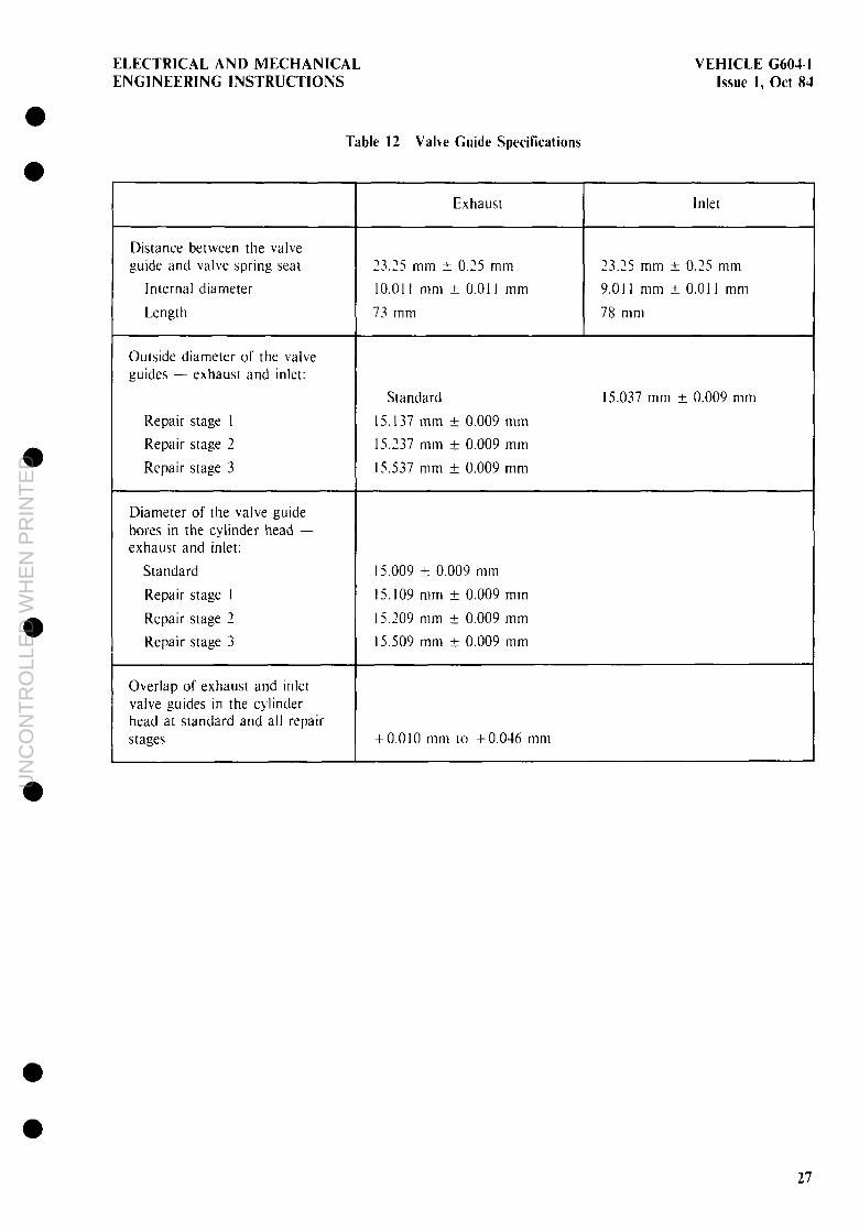
Table 12 Vahe Guide Specifications
Distance between the valve guide and valve spring seat
Internal diameter
Length
Outside diameter of the valve guides - exhaust and inlet:
Repair stage I
Repair stage 2
Repair stage 3
Diameter of the valve guide bores in the cylinder head - exhaust and inlet:
Standard
Repair stage I
Repair stage 2
Repair stage 3
Overlap of exhaust and inlet valve guides in the cylinder head at standard and all repair stages
Exhaust
?7 ‘5 mm + 0.25 mm -_ .--
IO.0 I I mm + 0.01 I mm
73 mm
Standard
IS.137 mm t 0.009 mm
IS.‘37 mm f 0.009 mm
15.537 mm +- 0.009 mm
15.009 +- 0.009 mm
15.109 mm -t 0.009 mm
15.209 mm k 0.009 mm
15.509 mm ?I 0.009 mm
Inlet
73.25 mm + 0.25 mm
9.0 I I mm + 0.01 I mm
78 mm
15.037 mm + 0.009 mm
+O.OlO mm to +0.046 mm
27
UN
CO
NT
RO
LLE
D W
HE
N P
RIN
TE
D

VEHICLE G604-1 ELECTRICAL AND MECHANICAL Issue 1, Ott 84 ENGINEERING INSTRUCTIONS
Table 13 Valve Clearances and Timings
Camshaft designation
Valve clearances set on a cold engine:
Inlet
Exhaust
Inlet valve opens
Inlet valve closes
Exhaust valve opens
Exhaust valve closes
Valve timmg check: Crankshaft angle (see NOTE)
352-S I
0.25 mm
0.40 mm
17” BTDC
II” ABDC
67” BBDC
13” ATDC
Valve lift at zero clearance
Inlet
Inlet
Exhaust
Exhaust
TDC 0.71 mm + 0.2 mm
BDC I.05 mm + 0.3 mm
TDC 0.67 mm +_ 0.1 mm
BDC 7.9, mm * 0.3 mm
NOTE: The crankshaft angles apply to valve operating clearances. Valve lift at the TDC and BDC settings is the recommended method for setting the valve timing. Checking by crankshaft angles may cause severe errors due to the shallow curves on the camshaft.
Prior to carrying out the valve timmg check. the valve operating clearances must be cancelled strip used to cancel the valve clearances must be at least 0.4 mm thick.
For practical purposes, it is usually sufficient to measure the valve timings on number I
Table I4 Rocker Assembly Specifications
The tolerance
cylinder.
Diameter of the basic bore in the rocker shaft support brackets 20.007 mm to 20.020 mm
Diameter of the rocker shafts 19.967 mm to 19.980 mm
Internal diameter of the rocker arm bushing 20.000 mm to JO.021 mm
Radial play of the rocker arms on the rocher shaft 0.02 mm to 0.054 mm
28
UN
CO
NT
RO
LLE
D W
HE
N P
RIN
TE
D

ELECTRICAL AND MECHANICAL VEHICLE G604-1 ENGINEERING INSTRUCTIONS Issue 1, Ott 84
Table I5 FI! I\ heel Specifications
Diameter I‘or the rrng-gear
Diameter for the cranhshaft flange mounrlng
Thickness of the securmg flange
335.39 mm [o 335.53 mm
130.020 mm + 0.020 mm
IS.20 mm * 0.20 mm
Distance between the clutch fact: and the flywheel securmg flange
Permissible allowable distance on the clutch face af’ter repalr
Total width of the flythee]
37.9 mm to 38.1 mm
I .O mm mauimum
51.5 mm maximum
Diameter of the fly~iheel face measured from inslde the face flange 365.OUO mm to 365.057 mm
Outslde diameter of the flywheel 375.10 mm f 0.10 mm
Permwble lateral runout of the flywheel relative to a diameter of 360.0 mm 0 1 mm maximum
Internal diameter of the ring-gear 334.860 mm + 0 030 mm
I I I I
Permwble lateral runout of the rmg.pear when fltted 10 the flywheel 0. I mm maxmium
Permiwble unbalance of the flywheel and rmg-gear measured at 1000 r.p.m. 20 grams/cm mauimuni
Permklble maxmum shanh length of the waked retaimng bolts I
26.3 mm
29
UN
CO
NT
RO
LLE
D W
HE
N P
RIN
TE
D

VEHICLE G604-1 ELECTRICAL AND MECHANICAL Issue 1, Ott 84 ENGINEERING INSTRUCTIONS
Turbocharger
24. This section details the repair procedures for the turbocharger. The relevant procedures are as follows:
Dismantling
25. Dismantle the turbocharger as follows (see Fig 131:
a. dismantling (refer to para 25).
b. inspection (refer to para 26), and
C. assembly (refer to para 271.
NOTE I. Because of the high rotational speeds and critical balance of the working parts. it is vital that a high standard of cleanliness is maintained when overhauling turbocharger com- ponents Dirt or foreign matter in the turbocharger will cause severe or ir- reparable damage to working parts.
2. Do not use abrasive cleaning materials or compounds to clean com- ponents, as machined surfaces could be damaged or destroyed. Use only recommended non-caustic solvents or cleaning agents.
3. The turbine wheel and rotor shaft are manufactured as a complete assembly and cannot be separated. The impeller wheel on the compressor side can be detached from the rotor shaft for overhaul purposes. However, because of the critical balance and weight factors involved. the turbme wheel, rotor shaft and impeller wheel must be replaced as matched components.
4. Always clean the exterior of the turbocharger before dismantling.
5. The manufacturers recommend replacement of the parts listed in Table 16 at each overhaul, or whenever the turbocharger is disassembled and these parts are removed.
a. Clean the exterior of the turbocharger; use only recommended non-caustic solvents or cleaning agents.
b. Match-mark the compressor housing ( I ). turbine housing (23),and centre housing (17) with a punch or scribe to facilitate orientating the housings during assembly.
1 I
C. Bend down the tabs on the lockplates (21): remove the bolts (3 and 20~. lockplates (21). clamps (2 and 22). and housings (I and 731.
d. Clamp a suitable socket spanner in a vice and. with the compressor wheel (5) upwards. engage the serrated end of the turbine wheel assembly (14) in the socket spanner.
NOTE If necessary. a turbine wheel-assembly holding-fixture can be fabricated to the dimensions shown in Fig I1 and used during removal of the locknut (4) (see Fig 151.
Table 16 Parts to be Replaced at Overhaul or Disassembly
Part
Bolt Lockplate Seal ring Piston ring Retaining ring Bearing
Figure 13
4. ‘0. 71 3 ” I9 -, --.
8 13. I6
II I2
e. Support the centre housing and rotatmg assembly in the vertical posttion and. us- ing a double universal and a socket span- ner to avoid imposing bending loads on the turbine wheelshaft. remove the locknut 14).
f. Lift the compressor wheel (51 off the shaft of the turbine wheel assembly ( 14) and in- vert the centre housing and turbine wheel assembly: remove the turbine wheel assembly with the piston ring ( 13) from the centre housing I 171; remove the piston ring from the turbine wheel assembly.
l
l
30
UN
CO
NT
RO
LLE
D W
HE
N P
RIN
TE
D

ELECTRICAL AND MECHANICAL ENGINEERING INSTRUCTIONS
VEHICLE C603-1 lssuc 1, Ott 83
a
0 0
1 16 15
1. Compressor housrng 2 Clamp 3 Bolt 4 Locknut 5. Compressor wheel 6 Backplate assembly 7. 011 seal 8. Thrust beanng 9. Spnng pin
10 Retalnlng ring 1 1. Bearing
12 Wheel shroud 13 Piston nng 14 Turbine wheel assembly 15 Piston nng 16. Thrust collar 17. Centre houslng 18. Lockplate 19. Bolt 20. Bolt 2 1. Lockplate 22. Clamp 23. Turbine houslng
Figure 13 Turbocharger Assembly
31
UN
CO
NT
RO
LLE
D W
HE
N P
RIN
TE
D

VEHICLE G6041 ELECTRICAL AND MECHANICAL Issue I. Ott 84 ENGINEERING INSTRUCTIONS
i. Do not remove the pins (91 from the cen-
38 tre housing ( 171 unless replacement of the
MIN pins is required. 113 b c 3
NOTE 1. Before cleaning. inspect all parts for burn-
; (--&,
ing, rubbing or other damage, that might not be evident after cleaning.
I3
1
66 6 I)”
ELEVEN HOLES IO DIA EQUALLY SPACED ON 742 PCD
7 Do not use abrasive cleaning methods -. which might damage or destroy machined surfaces.
j. Check the turbine-end oil cavity of the centre housing and remove all carbonized oil: if the centre housing includes an oil squirt hole, make sure that the hole is free
MATERIAL. HARDWOOD OR ALL~MINIUM
ASSEMBLE BLOCKS WITH SCREWS OR BOLTS
of carbonized oil or other foreign material isee Fig 161. If the hole is obstructed. clear it by running through with a wire of the same diameter as the hole.
Figure 14 Turbine Wheel Holding Fixture
Figure 15 Turbine Wheel in the Holding Fixture
l% Bend down the tabs on the lockplates I 181 and remove the bolts t 191. lockplates t 181. and backplate assembly 161.
NOTE If necessary, lightly tap the backplate assembly with a soft headed hammer to remove it from the centre housing.
h. Do not remove the spring pressed mto the backplate counterbore.
l
a
hole 2 Turbine end 011 cavity
Figure I6 Turbocharger Centre Housing - Sectioned View
Inspection
26. Inspect the turbocharger components as follows:
a. Inspect all bolts for worn. stripped or crossed threads and for corrosion. Threads must be free of corrosion and m good condition.
b. Inspect the compressor housing for damage caused by rubbing of the com- pressor wheel on the compressor housing: check all tapped holes for worn. stripped or crossed threads and for corrosion. Check the counterbore that mates with the backplate assembly for nicks. dents or warping that could prevent proper sealing with the backplate assembly.
l
32
UN
CO
NT
RO
LLE
D W
HE
N P
RIN
TE
D

ELECTRICAL AND MECHANICAL ENGINEERING INSTRUCTIONS
VEHICLE G604-1 Issue 1. Ott 84
0 a
0
l
c. Chech the compressor wheel nut for cracks and for nicked. worn. stripped. or crossed threads.
d. Check the compressor wheel for blade damage. erosion of the blade tops or foreign object Impact.
e. Check the turbine wheel assembly for rhe following defects.
III
I31
(31
I51
16)
Blade damage.
Blade tip erosion. Blade up rhlckness (for all blades1 must be not less than 0.635 mm.
Excessive wear of piston ring groove. The ring groove must be free of step wear. and the width of the groove must not exceed 1.87 mm.
Excessive wear of wheel hub adjacent to the piston ring groove. The hub diameter must be not less than 17.79 mm.
Excessike wear of bearing journals. The diameter of the Journals must be not less than IO. 145 mm. and the maximium out-of-roundness must not exceed 0.0015 mm.
Nicked. worn. stripped or crossed threads.
f. Check the wheel shroud for damage due to rubbing of the turbine wheel. for erosion. and for warping.
.Ec Inspect the backplate assembly for the following defects:
111 Worn or damaged backplate bore. The diameter of the bore between the piston rmg operating area (smaller diameter) and the com- pressor wheel must not exceed 12.725 mm. and the entire bore must be free of scratches and scores.
(2) Loose or damaged thrust spring. The spring must be securely pressed into the backplate counterbore. and it must be free of cracks, corrosion or surface damage from contact with the thrust bearing.
(3) Crached or warped backplate. The backplate-to-centre housing mounting surface must be flat
within 0.0127 mm total indicator reading.
Il. Inspect the thrust bearing for the follow- ing defects:
Scratching. scoring, galling or excessive wear of the bearing surfaces.
The bearing face that mates with the centre housing and the bearing surfaces that mate with the thrust collar must be flat withln 0 0076 mm total indicator reading.
Inspect the bearing bore for wear or damage caused by contact with the bottom of the bearing groove in the thrust collar as a secondary result of extreme journal bearing wear and radial shaft motion. The diameter of the bore must not exceed 10.972 mm.
Chech the oil passages in the thrust bearing for clogging with dirt or other foreign material. The 011 passages must be clean and free of all obstructions.
i. Inspect the thrust collar for the follow- ing defects:
(1) Scratchmg. scoring. galling or ex- cesslve wear of the sides and hot tom of the thrust bearing groove. The sides of the groove must be free of surface defects. and must be parallel to the collar face that is installed towards the centre housing. The width of the groove must not exceed 4.45 mm. The diameter of the bottom of the groove must be not less than 9.398 mm.
12) Step wear of the piston rmg groove. The width of the groove must not exceed 1.68 mm.
131 Scratching. scoring, galling or excessive wear of the thrust collar end surfaces. The end surfaces must be free of surface defects, and the) must be parallel wlthm 0.0025 mm total indicator reading.
i Inspect the centre housing bores for the following defects:
(I) All bore surfaces must be free of scratches and scores.
33
UN
CO
NT
RO
LLE
D W
HE
N P
RIN
TE
D
VEHICLE (3604-l ELECTRICAL AND MECHANICAL Issue 1, Ott 84 ENGINEERING INSTRUCTIONS
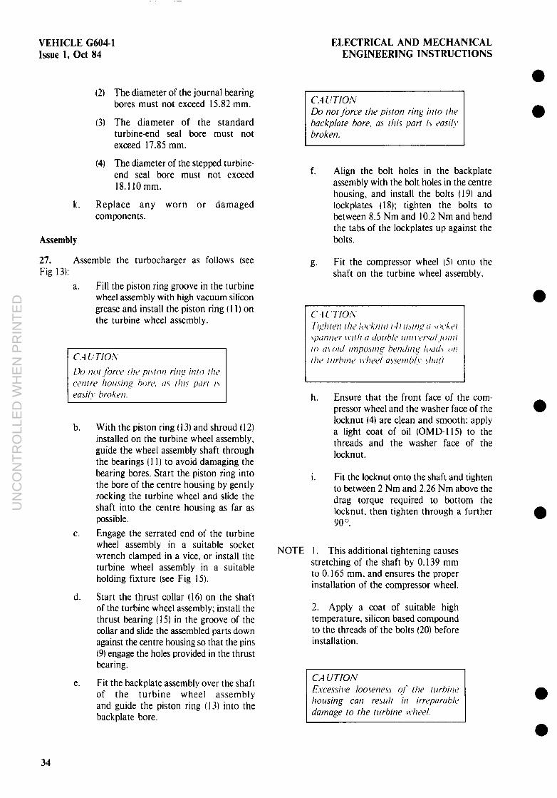
(2) The diameter of the journal bearing bores must not exceed 15.82 mm.
(3) The diameter of the standard turbine-end seal bore must not exceed 17.85 mm.
(4) The diameter of the stepped turbine- end seal bore must not exceed 18.llOmm.
k. Replace any worn or damaged components.
Assembly
27. Assemble the turbocharger as follows (see Fig 13):
Fill the piston ring groove in the turbine wheel assembly with high vacuum silicon grease and install the piston ring ( 11) on the turbine wheel assembly.
b. With the piston ring ( 13) and shroud I 12) installed on the turbine wheel assembly, guide the wheel assembly shaft through the bearings (1 1) to avoid damaging the bearing bores. Start the piston ring into the bore of the centre housing by gently rocking the turbine wheel and slide the shaft into the centre housing as far as possible.
C. Engage the serrated end of the turbine wheel assembly in a suitable socket wrench clamped in a vice, or install the turbine wheel assembly in a suitable holding fixture (see Fig 15).
d. Start the thrust collar (16) on the shaft of the turbine wheel assembly; install the thrust bearing (15) in the groove of the collar and slide the assembled parts down against the centre housing so that the pins (9) engage the holes provided in the thrust bearing.
e. Fit the backplate assembly over the shaft of the turbine wheel assembly and guide the piston ring (13) into the backplate bore.
Do nor Jbrce the pivrot? ritq irun I/W backplare bore, as this purl i\ easi!\, broken.
f. Align the bolt holes in the backplate assembly with the bolt holes in the centre housing, and install the bolts (19) and lockplates 118); tighten the bolts to between 8.5 Nm and 10.2 Nm and bend the tabs of the lockplates up against the bolts.
g. Fit the compressor wheel (51 onto the shaft on the turbine wheel assembly.
h. Ensure that the front face of the com- pressor wheel and the washer face of the locknut (4) are clean and smooth; apply a light coat of oil (OMD-I 15) to the threads and the washer face of the locknut.
i. Fit the locknut onto the shaft and tighten to between 2 Nm and 2.26 Nm above the drag torque required to bottom the locknut, then tighten through a further 90 0.
NOTE I. This additional tightening causes stretching of the shaft by 0.139 mm to 0.165 mm. and ensures the proper installation of the compressor wheel.
2. Apply a coat of suitable high temperature, silicon based compound to the threads of the bolts (20) before installation.
E.wessive looseness of rhe rurbitw
damage lo rhe turbine )~.heel.
a a
l
l
34
UN
CO
NT
RO
LLE
D W
HE
N P
RIN
TE
D

ELECTRICAL AND MECHANICAL ENGINEERING INSTRUCTIONS
VEHICLE G60d-1 Issue 1, Ott 84
0 0
0
j. After attaching the turbine housing (23) to the centre housing and rotating assembly. install and tighten the bolts (20) just enough to prevent the turbine wheel from contacting the housing, but loosely enough to permit the turbine housing to rotate with respect to the centre housing. Do not bend up the tabs of lockplates (2 I) at this time.
k. Secure the assembled parts so that the compressor wheel is facing upwards and install the compressor housing (I 1 on the backplate assembly. Install the clamps (2). and bolts (3). Tighten the bolts just enough to prevent the housing from con- tacting the compressor wheel, but loosely enough to permit the compressor housing to rotate with respect to the centre housing.
I. If match marks applied to the turbine housing and the centre housing during dismantling are visible. align these marks. Tighten the bolts (301 to between I I .3 Nm and 14.7 Nm. and bend the tabs of the lockplates up against the bolts.
m. Tighten the bolts (3) and (19) to between 15.8 Nm and 19.2 Nm.
n. Pour sufficient clean OMD-I 15 oil into the centre housing to pre-lubricate and protect the working parts. If the turbo- charger is to be stored, seal all openings with clean covers to prevent dirt entering the turbocharger.
MAIN TRANSMISSION
28. This section contams the repair procedures and specification tables for the main transmission. The main transmission assembly is made up of a number of sub- assemblies. A general view of the transmission is shown in Figure 17. For the purpose of easier explanation, the overhaul procedures for the transmission have been broken down into these sub-assemblies as follows:
a. intermediate housing - rear (refer to para 291,
b. intermediate housing - front [refer to para 331.
C. transfer case lrefer to para 371, and
d. main gearbox (refer to para 41’1
NOTE 1. A high standard of cleanliness is essential when repairmg the trans- mission. Dirt, dust or foreign matter in the gearbox acts as an abrasive and results in rapid wear of, and damage to. transmission components.
’ Clean the gearbox before &. dismantling.
3 -. Protect all breather openings and rubber or nylon lines from direct steam application with suitable covers.
4. Clearances and tolerances for the transmission are listed in Table 17.
5. Use only oil-bath or oven heatmg techniques as appropriate to heat gears or bearings. Refer to the Workshop Standing Orders applicable to these procedures.
6. Use only the correct pullers, presses and collars to remove and fit bearings and gears.
7. After cleaning and drying transmission components, lightly coat the components with clean OMD-I15 oil. Protect those components not im- mediately required. by covering with a clean, lightly oiled cloth.
8. Lubricate all bearings with clean OMD- 115 oil before mstallation.
Intermediate Housing - Rear
29. The intermediate housing with components for the drive to the rear axle can be overhauled as a separate unit as follows:
a. removal (refer to para 30).
b. repair (refer to para 311, and
C. installation (refer to para 32).
30. Removal. Remove the intermediate housing and drive components as follows:
35
UN
CO
NT
RO
LLE
D W
HE
N P
RIN
TE
D

VEHICLE G604-I Issue 1, Ott 84
ELECTRICAL AND MECHANICAL ENGINEERING INSTRUCTIONS
16
2. 3 4 5 6 7 a. 9.
Shift cylinder Power Input shaft Synchromesh mechanism Counter shaft MaInshaft assembly Selector forks Shift mechanism 412 way air valve Epqcl~c gear train
10. 11. 12 13 14 15 16 17.
9 a 7 6 5
i 10
Drive shaft to rear axle Intermediate housing - rear Intermediate drive gear Dog clutch ~ FW drive Intermediate houslng - front Idler gear Transfer gear Transfer case end cover
a
a Figure 17 Main Transmission Assembly
36
UN
CO
NT
RO
LLE
D W
HE
N P
RIN
TE
D

ELECTRICAL AND MECHANICAL VEHICLE G604-1 ENGINEERING INSTRUCTIONS Issue 1, Ott 84
0 0
0
a
Table 17 Main Transmission Specifications
Model
Type designation
Main gearbox:
Primary shaft end-float
Layshaft end-float
Mainshaft end-float
Permissible synchro-lash
Selector shaft adjustment
Epicyclic gear assembly:
717,901
UG3/40-8113.01 CPA
0.03 mm to 0.05 mm
0.06 mm + 0.02 mm
0.03 mm + 0.02 mm
0.7 mm + 0.2 mm minimum 2.0 mm maximum
100.6 mm f 0. I mm
Permissible side float for the deep-groove ball-bearing in the planetary gear carrier
Permissible synchro-lash
0.4 mm maximum
I.0 mm + 0.3 mm minimum 2.0 maximum
Shift cylinder adjustment
Selector lever angle (upwards)
Transfer case:
240.2 mm to 242.2 mm
30”
Permissible end-float for the input gear in the transfer case 0.06 mm + 0.02 mm
Permissible end-float for the idler gear 0.05 mm kO.03 mm
Permissible end-float for the intermediate gear 0.06 mm kO.02 mm
37
UN
CO
NT
RO
LLE
D W
HE
N P
RIN
TE
D

VEHICLE G604-1 ELECTRICAL AND MECHANICAL Issue 1, Ott 84 ENGINEERING INSTRUCTIONS
_- d
A---_
1
1. Transfer casing 2. Speedometer drwe spindle 3. IntermedIate houslng - rear
4 Speedometer angle drive reduction box 5 Shift mechanism
a a
a
a
a
a a Figure 18 Speedometer Drive Spindle
38
UN
CO
NT
RO
LLE
D W
HE
N P
RIN
TE
D

ELECTRICAL AND MECHANICAL VEHICLE C604-1 ENGINEERING INSTRUCTIONS Issue I, Ott 84
a
NOTE To facihtate easier handlmg and access to transmission components. secure the transmission assembly in a suitable cradle or trestle.
a
0
a 0
a. Remove the drain plugs and allow all oil to drain from the assembly.
b. Remove the bolts and the thrust plate securing the shaft flange to the mtermediate shaft for the rear axle drive.
C. Lever the flange off the intermedtate shaft.
d. Remove the speedometer drive spmdle from the intermediate housing (see Fig 18).
e. Remove the bolts securing the intermedlate housing to the transfer case; use a soft headed hammer to lightly strihe the intermediate housing around the outer flange until the bond between the two is broken; remove the intermediate housing from the transfer case.
f. Withdraw the intermediate drive shaft. gear and bearings from the transfer case; remove the 011 baffle from the transfer case (see Fig I91.
the drive shaft; take note of the position of the bearings on the shaft for repair purposes.
NOTE The spigot on the intermediate shaft for the front wheel drive, locates in a needle bearing in the tail end of the Intermediate shaft for the rear wheel drive.
I. Remove the needle bearing from the shaft and discard the bearing.
31. Repair. Repair the intermediate housing and drive components as follows:
a. Clean and inspect the intermediate housing and transfer case; ensure that no gasbet residue is left adhering to the intermediate housing and transfer case.
b. Clean and inspect all components.
Figure 19 Transfer Gears and Oil Baffle
g. Remove the drove shaft flange oil-seal from the transfer case; use a soft drift and hammer to remove the outer bearing race from the transfer case; remove the inner bearing race from the transfer case.
h. Remove the speedometer drive gear from the drive shaft; use a puller and sultable collars to remove the two bearings from
C. Use a press with suitable hollow drifts or collars to fit the bearings to the drive shaft; ensure that the bearings are correctly seated on the drive shaft: fit the needle bearing into the tail end of the shaft.
d. Fit the inner bearing race to the transfer case: fit the outer bearing race to the
39
UN
CO
NT
RO
LLE
D W
HE
N P
RIN
TE
D

VEHICLE G604-1 Issue 1, Ott 84
ELECTRICAL AND MECHANICAL ENGINEERING INSTRUCTIONS
l
a
1. Bolt 2. Lock washer 3. Thrust plate 4. Supportrng drsc 5. Taper roller beanng 6. Idler gear 7. 0-nng 8. Idler shaft 9. O-ring
10. Thrust plate 11. Shaft flange
12. 011 seal 13. Crrclrp 14. Ball beanng 15. Dog clutch 16. Spacer sham 17. Taper roller bearrng 18. Gear shaft 19. Needle roller beanng 20. Transfer gear 2 1. Taper roller beanng 22. Speedometer drive gear
Figure 20 Transfer Case Components
40
UN
CO
NT
RO
LLE
D W
HE
N P
RIN
TE
D

ELECTRICAL AND MECHANICAL ENGINEERING INSTRUCTIONS
VEHICLE G604-1 Issue I, Ott 84
intermedtate housing; ensure that the race butts fully against the buttress collar: in both instances a soft drift and hammer may be used to drive the races fully home.
e. Clean and blow dry the drive shaft assembly again; this ensures that no dirt remains in the bearings.
f. Lightly lubricate the bearings with clean OMD- I 15 oil; rotate the bearings a few times by hand to check for free movement.
32. Installation. Install the intermediate housing and drive components as follows:
a.
b.
C.
d.
e.
f.
g.
h.
I.
Lightly coat the gasket for the inter- mediate housing with XC-274 multi- purpose grease; attach the gasket to the flange on the intermediate housing.
Install the oil baffle jn the transfer case: ensure that the oil baffle slots under the retaining lugs in the opposite side of the transfer case.
Install the drive shaft assembly in the transfer case: fit the intermediate housing to the transfer case so that the hole for the speedometer drive spindle is upper- most; install and tighten the retaining bolts to 33 Nm.
Fit the speedometer drive gear to the drive shaft; a soft drift and hammer may be used to drive the speedometer drive gear fully home.
Install the speedometer drive spindle into the intermediate housing; tighten the locknut.
Coat the oil seal for the drive shaft flange with rubber grease; fit the oil seal to the transfer case; ensure that the oil seal is correctly seated in the case.
Fit the flange onto the drive shaft; do not damage the lips on the oil seal.
Install the thrust plate and retaining bolts; tighten the retaining bolts to 75 Nm.
Install and tighten the drain plugs; attach a NO OIL label to the transmission assembly; remove the assembly from the cradle or trestle.
Intermediate Housing - Front
33. The intermediate housing with components for the drive to the front axle can be overhauled as a separate unit, as follows:
a. removal (refer to para 34),
b. repair (refer to para 351, and
C. installation (refer to para 36).
34. Removal. Remove the intermediate housing and drive components as follows (see Fig 201:
NOTE To facilitate easier handling and access to transmission components. secure the transmission assembly in a suitable cradle or trestle.
a.
b.
C.
d.
Remove the drain plugs and allow all oil to drain from the assembly.
Remove the bolts (1) and the thrust plate t IO) securing the companion flange (1 1 I to the intermediate shaft for the front axle drive.
Lever the flange off the intermediate shaft.
Remove the bearing shroud from the housing: remove and discard the flange oil seal ( 12) from the shroud; remove and discard the shims.
Figure 21 Bearing Shroud
e. Remove the bolts and two nuts securing the intermediate housing to the transfer case; if necessary. use a soft headed hammer to lightly strike the housing around the outer flange until the bond between the two is broken.
f. Support the intermediate housing assembly and move the assembly away from the transfer case until clear of the two long mounting studs.
41
UN
CO
NT
RO
LLE
D W
HE
N P
RIN
TE
D

VEHICLE G604-I ELECTRICAL AND MECHANICAL Issue 1, Ott 84 ENGINEERING INSTRUCTIONS
g. Remove the retaining bolts securing the shift cylinder for the front wheel drive selector to the intermediate housing: detach the cylinder and actuating piston from the housing.
h. Remove the actuating piston from the cylinder; remove and discard the O-ring from the actuating piston.
i. Remove the drive shaft (18) from the housing: the shaft bearing I I91 will come away with the shaft during removal; use a suitable hollow drift and press to remove the bearing from the shaft.
j. Remove the selector fork return spring. selector fork and sliding dog clutch t 15) from the housing.
35. Repair. Repair the intermediate housing drive components as follows:
a. Clean and mspect the intermediate housing and transfer case; ensure that no gasket residue is left adhering to the inter- mediate housing and transfer case.
b. Clean and inspect all components; replace any worn or damaged components.
C. Coat the O-ring for the actuating piston with rubber grease; fit the O-ring to the piston and install the piston into the shift cylinder.
d. Lightly coat the shift cylinder gasket wtth KG-274 multipurpose grease: attach the gasket to the flange on the shift cylmder: position the shift cylinder on the inter- mediate housing so that the bolt holes are aligned: install and tighten the retaming bolts to 15 Nm.
e. Fit the selector fork and sliding dog clutch t 151 to the intermediate housing; ensure that the bore in the small end of the selector fork encompasses and slides smoothly over the piston shaft.
f. Fit the return spring into the spring bore in the selector fork.
g. Lightly coat the gasket for the Intermediate housing with ,XG-274 multipurpose grease; attach the gasket to the flange on the intermediate housing: lightly coat the spacer shim 1161 for the taper roller bearing (I71 with XC-374 grease; fit the shim into the groove in the intermediate housing.
h. Use a suitable hollow drift and press to fit the roller bearing onto the drive shaft
I 181; ensure that the bearing is correctly seated on the shaft.
Clean the drive shaft and bearing again; 0 this ensures that no dirt remains in the bearing.
Lightly lubricate the drive shaft and roller bearing with clean OMD- I I j oil: rotate the bearing by hand a few times to check for free movement.
36. Installation. Install the intermediate housing drive components as follows:
a. Install the drive shaft t 18) mto the inter. mediate housing.
b. Fit the intermediate housing to the transfer case: do not displace the shim or gasket during this procedure: install and tighten the retatning bolts to 33 Nm: fit a the two locknuts to the retaining studs and tighten to 33 Nm. Ensure that the spigot on the shaft fits correctly into the needle bearing t 191 m the shaft of the rear drive assembly (201.
C. Coat the drove flange oil seal (121 with rubber grease and install the seal into the housing over the drive shaft: do not damage the lips on the oil seal: ensure a that the oil seal is correctly seated m the housing.
d. Fit the flange (I I) onto the drive shaft; do not damage the lips on the oil seal.
e. Install the thrust plate t IO) and retaining bolts I II: tighten the retaining bolts to 75 Nm.
f. Install and tighten the dram plugs: attach a NO OIL label to the transmission
l assembly: remove the assembly from the cradle or trestle.
Transfer Case
37. The transfer case and gears are an integral umt within the main transmission assembly and can be overhauled separately. The relevant procedures are as follows:
38.
NOTE
a. removal (refer to para 381.
b. repair (refer to para 39). and
C. installation (refer to para 401.
Removal. Remove the transfer case as follows:
To facilitate easier handling and access to transmission components. secure the transmission assembly In a suttable cradle or trestle.
42
UN
CO
NT
RO
LLE
D W
HE
N P
RIN
TE
D

ELECTRICAL AND MECHANICAL VEHICLE C604-1 ENGINEERING INSTRUCTIONS Issue I, Ott 84
a 0
0
0 a
Remove the drain plugs and allow all oil to drain from the assembly.
Remove the Intermediate housing and components for the front wheel drive (refer to para 341.
Remove the intermediate housing and components for the rear wheel drive (refer to para 29).
Remove the bolts and nuts securing the end cover to the transfer case; detach the end cover from the transfer case (see Fig 22).
Figure 22 Transfer Case End-cover Removal
e. Rotate the transmission assembly through 9OOso that the transfer case is uppermost; screw a lifting eye-bolt and D-shackle into the centre bolt hole in the transfer case; attach the D-shackle to an overhead lifting device and carefully raise the transfer case off the main gearbox until clear of the long retaining studs. Move the transfer box to a workbench or similar level working surface, and remove the lifting eye-bolt and D-shackle from the transfer case.
NOTE Mark the assembly position of the idler gear shaft to the transfer case with a punch.
f. Remove the bolts and thrust plate securing the idler assembly in the transfer case; discard the shim (see Fig 23).
ii5 Support the idler gear assembly and remove the idler shaft from the transfer case; if difficulty is experienced, a soft headed hammer may be used to drive the idler shaft from the transfer case.
h. Remove the idler gear assembly from the transfer case: take note of the orientation of the idler gear for later installation purposes (see Fig 23).
i. Remove the taper roller bearings from the idler gear; use a soft drift and hammer to remove the bearing outer races from the idler gear; remove the O-ring from the idler shaft.
39. Repair. Repair the transfer case and com- ponents as follows:
a.
b.
C.
d.
e.
Clean and inspect the transfer case, inter- mediate housings and main gearbox: ensure that no gasket residue is left ad- hering to any components.
Clean and inspect all components; replace any worn or damaged components.
Fit the bearing outer races into the idler gear; ensure that the races are correctly seated against the inner collars in the idler gear; fit a new O-ring to the idler shaft.
Lightly lubricate the bearings with clean OMD-I I5 oil; install the bearings in the idler gear: support the two bearings in the idler gear and position the idler gear in the transfer case so that the idler shaft can be fitted.
Install the idler shaft so that the oil channel in the shaft is aligned with the oil passage in the transfer case (see Fig 24).
NOTE To obtain the specified end-float for the idler shaft, shims of appropriate thickness must be installed behind the thrust plate. To determine the thickness of the shims required, measure the end-float of the idler shaft without shims installed and then ob- tain the correct shims to bring the end- float within specifications (refer to Table 17).
f. Fit two thrust plates to the idler shaft; fitting two discs prevents distortion when tightened down and ensures the accurate measurement of end-float; install the retaining bolts and tighten to 75 Nm.
iit. Slacken off the retaining bolts and re- tighten; with the idler gear raised against the inside of the transfer case. use a dial indicator gauge attached to a magnetic base-stand to measure the end-float of the idler shaft.
43
UN
CO
NT
RO
LLE
D W
HE
N P
RIN
TE
D

VEHICLE G604-1 ELECTRICAL AND MECHANICAL Issue 1, Ott 84 ENGINEERING INSTRUCTIONS
Figure 23 Idler Gear and Shaft Removal
using a soft headed hammer. tap the Idler shaft a few times so that the assembl! beds-in.
j. Raise the idler gear agamst rhe inside of the transfer case. and measure the end- float of the idler shaft again (refer to
1 Table 17); adjust the shims if necessary.
40. Installation. Install the transfer case as follows:
a. Screa a lifting eye-bolt and D-shackle into the centre bolt hole in the transfer
2 case: attach the D-shackle to an overhead lifting device and move the transfer case into position directly above the main gearbox.
b. Lightly coat the gaskets for the trans- mlssion assembly with SC-274 multi- purpose grease and attach the gaskets to the main gearbox and transfer case.
1 Idler shaft 011 channel 2. Idler shaft 3. Idler shaft bearing
Figure 24 Idler Shaft Oil Channel
h. Remove the retaining bolts and thrust plates from the idler shaft; obtain a shim or shims of the correct thickness to bring the end-float within specifications: 0.25 mm must be added to the measure- ment to obtain the correct shim thickness.
i. Fit the shim&) and thrust plate to the idler shaft; install and tighten the retaining bolts to 75 Nm; support the idler gear from below with a lever and
C. Lower the transfer case onto the main gearbox.
d. Fit the end cover to the transfer case: in- stall the retaining bolts and nuts and. using a diagonal tightening sequence. tighten rhe bolts and nuts fo 75 Nm.
e. Rotate the transmission assembl) through a 90” so that the assembly 1s horizontal.
f. Fit the intermediate housmg and come ponents for the rear wheel drive rrefer to para 221.
g. Fit the intermediate housing and com- ponents for the front wheel drive (refer to para 36).
a
l
44
UN
CO
NT
RO
LLE
D W
HE
N P
RIN
TE
D
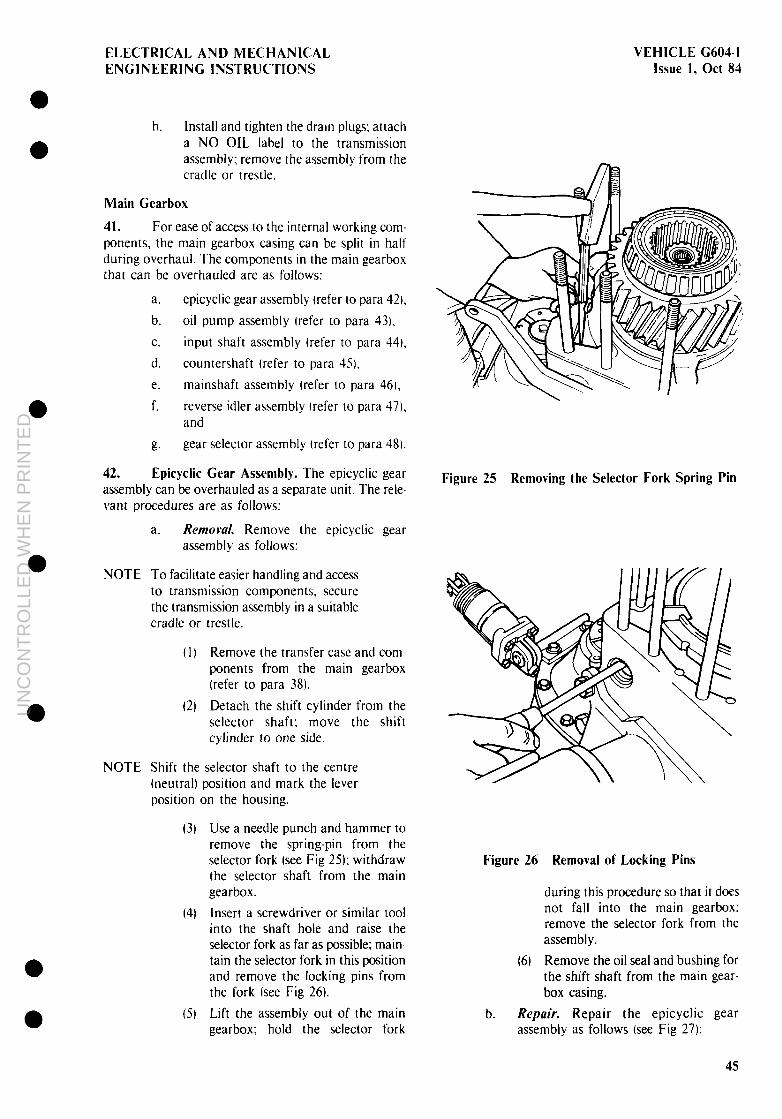
ELECTRICAL AND MECHANICAL ENGINEERING INSTRUCTIONS
VEHICLE G604-1 Issue 1, Ott 84
h. Mall and tighten the dram plugs; attach a NO OIL label to the transmission assembly; remove the assembly from the cradle or trestle.
Main Gearbox
41. For ease of access to the internal working com- ponents, the main gearbox casing can be split in half during overhaul. The components in the main gearbox that can be overhauled are as follows:
a. epicyclic gear assembly (refer to para 42).
b. oil pump assembly (refer to para 331,
C. input shaft assembly (refer to para 44.
d. countershaft (refer to para 451,
e. mainshaft assembly (refer to para 461,
f. reverse idler assembly (refer to para 47). and
g. gear selector assembly (refer to para 48).
42. Epicyclic Gear Assembly. The epicyclic gear assembly can be overhauled as a separate unit. The rele- vant procedures are as follows:
a. Removal Remove the epicyclic gear assembly as follows:
NOTE To facilitate easier handling and access to transmission components, secure the transmission assembly in a suitable cradle or trestle.
(I l Remove the transfer case and com- ponents from the main gearbox (refer to para 38).
(2) Detach the shift cylinder from the selector shaft; move the shift cylinder to one side.
NOTE Shift the selector shaft to the centre (neutral) position and mark the lever position on the housing.
(3) Use a needle punch and hammer to remove the spring-pin from the selector fork (see Fig 25); withdraw the selector shaft from the main gearbox.
(4) Insert a screwdriver or similar tool into the shaft hole and raise the selector fork as far as possible; main- tain the selector fork in this position and remove the locking pins from the fork (see Fig 26).
(51 Lift the assembly out of the main gearbox; hold the selector fork
Figure 25 Removing the Selector Fork Spring Pin
Figure 26 Removal of Locking Pins
during this procedure so that it does not fall into the main gearbox; remove the selector fork from the assembly.
(61 Remove the oil seal and bushing for the shift shaft from the main gear- box casing.
b. Repair. Repair the epicyclic gear assembly as follows (see Fig 27):
45
UN
CO
NT
RO
LLE
D W
HE
N P
RIN
TE
D

UN
CO
NT
RO
LLE
D W
HE
N P
RIN
TE
D

ELECTRICAL AND MECHANICAL ENGINEERING INSTRUCTIONS
VEHICLE G60-4.1 Issue 1, Ott 84
0 l
l
0 0
(I)
(2)
I31
(11
(61
(7)
Clean the assembly.
Remove the synchroniser 17) and the oil deflector plate from the assembl!,: remove the retaming circlip and ball bearing from the synchroniser: use a soft drift and hammer IO remove the bearmg. if necessary.
Remobe the compensating shun (9) and spacer tube (1 II from the assembly: remove the circlip securing the synchro-hub ( I3 to the annulus (14 and remove the synchro-hub from the assembly.
Fit soft jaws on a bench vice: clamp the assembly in the vice with the annulus dome I 131 uppermost: remove the snap-ring ( 191 securmg the dome to the annulus: use a soft headed hammer to knock the dome downwards off the annulus.
Remove the planetary gear carrter (171 from the annulus: remove the retaining circlip ( 161 and remove the ball bearmg (I 51 from the annulus: a soft drift and hammer may be used to drive the bearing from the annulus. if necessary.
The shafts that carry the planetary gears are locked m positton by grub- screws. located in the carrier flange (see Fig 18): remove the grub-screws; use a soft drift and hammer to remove the planetary gear shafts from the carrier: remove the planetary gears. tab-shims and frvxon washers.
Remove the needle rollers from inslde the planetary gears; clean and inspect all components. replace any worn or damaged components.
NOTE The needle rollers in the planetary gears are installed individually: when exchanging needle rollers. the entire set must be renewed; do not mix old and new rollers.
(8) Lightly coat the needle rollers with XG-774 multipurpose grease and install them in the planetary gears: lightly coat the friction washers and
Figure 28 Planetar! Gear Shafts Grub Screws
Tab-shims with XG-774 multi- purpose grease; attach the friction washers and the tab-shims to each side of the planetary gears.
(91 Install the planetary gears indivtd- ually Into the carrier; do not displace the tab-shims or friction washers during this procedure; align the gear so that the gear shaft can be installed.
1101 Install the gear shaft through the flange and gear; ensure that the recess in the shaft is aligned with the grub-screw hole in the carrier flange; install and tighten the grub-screw to lock the shaft in position: lock-up the grub-screw using a centre-punch or chisel; repeat these procedures to complete the installation of the remaining planetary gears.
(I I I Fit the ball-bearing (151 into the annulus (141; install the clrclip ( 161: fit the planetary gear carrier (I 71 to the annulus; ensure that the teeth on the annulus and planetary gears are correctly meshed.
47
UN
CO
NT
RO
LLE
D W
HE
N P
RIN
TE
D

VEHICLE G604-I Issue 1, Ott 84
ELECTRICAL AND MECHANICAL ENGINEERING INSTRUCTIONS
(12) Fit the annulus dome (131 over the annulus: install the snap-ring t 191 to secure the dome in position; fit the synchro-hub ( I21 to the assembly; press the synchro-cone onto the assembly until the circlip groove is clear; fit the circlip to secure the hub in position.
f 131 Fit the spacer tube I I I1 and compen- sating shim 19) to the assembly; ensure that the oil drilling in the spacer tube faces inwards when fitting the tube.
(Id) Install the ball bearing in the syn- chroniser (7); install the circlip to secure the ball hearing in position.
(15) Fit the synchroniser and the oil deflector plate to the assembly; fit the transfer gear and bearing to the assembly; install and tighten the centre bolt to 75 Nm.
(16) Support the assembly on two blocks (see Fig 291; use a feeler gauge to measure the play of the synchro-hub (refer to Table 17).
NOTE If the play for the synchro-hub is out- side specifications. remove the transfer gear and bearing, and install a com- pensating shim(s) of the correct thickness to bring the play within specifications.
Figure 29 Measuring Play at Synchro Hub
(I 7) Remove the centre bolt, transfer gear and bearing from the assembly: fit the bushing and oil seal for the shift shaft into the main gearbox casing.
C. Insrallarion. Install the epicyclic gear assembly as follows:
(I)
(2)
(3)
(4
Fit the selector fork to the synchro- hub: hold the selector forh m position and carefully lower the assembly into the main gearbox: do not displace the oil deflector plate.
Align the planetary gear splines with the sun-gear splines; lower the assembly until it beds fully home: ensure that the spigot on the end of the mainshaft slots exactly into the bushing in the planetary gear carrier.
Insert a screwdriver or similar tool into the shaft hole and raise the selector fork as far as possible; main tain the selector fork in this position and install the locking pins in the fork.
Fit the selector shaft to the assembly in such a way that the lever on the end of the shaft is about 30” up- wards from the horizontal positon. measured along the centre of the lever, install the spring-pin through the selector fork to secure the fork and shaft in position.
NOTE Always fit new spring-pins.
(5) Adjust the shift cylinder (refer to VEHICLE G6031; attach the shift cylinder to the selector lever.
(61 Fit the transfer case and com- ponents to the main gearbox (refer to para 40). l
(71 Install and tighten the oil drain plugs; attach a NO OIL label to the transmisston assembly; remove the assembly from the cradle or trestle.
43. Oil Pump Assembly. The oil pump assembly can be overhauled as a separate unit. The relevant procedures are as follows (see Fig 30):
a. Remowl. Remove the oil pump as follows:
(11 Remove the centre bolt II) and thrust plate (31 securing the flange 151 to the input shaft in the main gearbox; lever the flange off the input shaft. 0
(21 Remove the bolt (6) and clamp 191 securing the oil pump in the main gearbox (see Fig 3 I).
l
48
UN
CO
NT
RO
LLE
D W
HE
N P
RIN
TE
D

UN
CO
NT
RO
LLE
D W
HE
N P
RIN
TE
D

VEHICLE G604-1 ELECTRICAL AND MECHANICAL Issue 1, Ott 84 ENGINEERING INSTRUCTIONS
Figure 31 Oil Pump Clamp and Retaining Bolt
(3) Use Special Tool No. 2 to withdraw the oil pump from the gearbox (see Fig 32); remove the Woodruff key from the input shaft.
Figure 32 Withdrawing the Oil Pump
b. Repair. Repair the oil pump assembly as follows:
( I) Remove the socket head bolts ( 16) securing the housing ( 14) to the oil pump body (10); remove the hous- ing from the body; remove the O- ring (I I) and oil seal (8) from the pump body.
(2) Remove the two ring gears (II, 13) that make up the pumping element from the pump body.
(3) Clean and inspect the pump body and all components; replace any worn or damaged components.
NOTE The two ring gears must be replaced as matched components; do not mix worn and new ring gears.
(41
15)
Lightly coat the oil pump body and ring gears with clean OMD- I I5 oil; coat the O-ring and oil seal with rubber grease.
Install the two ring gears (12. 13) into the pump body ( IO); rotate the ring gears a few times by hand to en- sure free movement; install the O- ring, then fit the body into the hous- ing; install and tighten the socket head bolts.
C. Installation. install the oil pump assembly as follows:
(1)
(2)
13)
14)
Fit the oil pump over the input shaft so that the collar on the pump body is aligned with the hole for the clamp.
Press the oil pump fully home in the main gearbox; if necessary, a soft headed hammer may be used to lightly tap the oil pump to drive it fully home.
Fit the clamp (9) then install and tighten the retaining bolt (6) to 25 Nm.
Fit the Woodruff key then fit the flange (5) to the input shaft; fit the thrust plate and O-ring (3), then in- stall and tighten the flange centre bolt (1) to 75 Nm.
44. Input Shaft Assembly. The input shaft and components that make up the assembly can be removed as separate items. The relevant procedures are as follows:
NOTE
a. Remowl. Remove the input shaft assembly as follows:
To facilitate easy handling and access to components, secure the transmis- sion assembly in a suitable cradle or trestle.
( 1) Remove the drain plugs and allow all oil to drain from the transmission assembly.
(2) Remove the shift cylinder and mounting bracket (refer to VEHICLE G603).
l
a
a
50
UN
CO
NT
RO
LLE
D W
HE
N P
RIN
TE
D

ELECTRICAL AND MECHANICAL ENGINEERING INSTRUCTIONS
VEHICLE G604-I Issue I, Ott 84
(3) Remove the oil pump (refer to para 43).
(41 Remove the transfer case from the main gearbox (refer to para 381.
(51 Remove the epicyclic gear assembly (refer to para 42).
NOTE The casing for the epicyclic gear assembly is bolted to the main gear- box. The bolts that secure the two cases together are located along the flange around the outside of the epicyclic gear casing and inside the epicyclic gear casing.
(6) Remove the securing bolts from inside the epicyclic gear casing.
(7) Rotate the transmission assembly through 180 O until the main gearbox is uppermost; remove the bolts securing the end covers to the main gearbox; remove the end covers; remove the bolts securing the bearing caps in position, and remove the bearing caps (see Frg 33); remove and discard the oil seals.
NOTE
Figure 33 End Covers and Bearing Caps
(8) Remove the retaining bolts and detach the shift mechanism from the main gearbox; remove the screw plugs for the selector rods (see Fig 34).
(91 Move the forward/reverse selector fork to the reverse position; use a pin-punch and hammer to remove the spring pin from the forward/reverse selector fork (see Fig 3j).
=5
Figure 34 Selector Rod Screw Plugs
Figure 35 Spring Pin
Move the forward/reverse selector shaft to the centre (neutral1 position and mark the position on the housing.
1101 Withdraw the selector shaft from the forward/reverse selector fork.
I I I) Remove the bolts securing the main gearbox casing to the casing for the epicyclic gear assembly; raise the selector forks as much as possible and remove the main gearbox casing.
(I?) Remove the selector fork from the input shaft assembly.
t 13) Remove the gear selector assembly by lifting it upwards and out of the casing.
51
UN
CO
NT
RO
LLE
D W
HE
N P
RIN
TE
D

VEHICLE (2604-l Issue 1. Ott 84
ELECTRICAL AND MECHANICAL ENGINEERING INSTRUCTIONS
l (13) Tilt the three shafts apart; remove
the input shaft assembly; clean the input shaft assembly and all com- ponents to be used during installation.
b. Repair. Repair the input shaft assembly as follows:
t I) Use a puller to dismantle the input shaft assembly (see Fig 36); take particular note of the position of components and the sequence of removal for assembly purposes; a general view of the input shaft is shown in Fig 37.
Figure 36 Removing the Input Shaft Gearset
(3) Clean and inspect all components; replace any worn or damaged components.
13) Assemble the input shaft assembly using standard workshop practices and processes, in the reverse sequence to dismantling.
(41 Clean the assembly again. then light- ly coat the assembly with clean OMD- I I5 oil.
C. fnsralfation. install the input shaft assembly as follows:
(I) Fit the gear selector assembly for lstllnd and 3rd/4th gears.
NOTE The selector forks and rods must be adjusted before final installation.
(I!) Install the assembly in the gear box together with the gutde plate.
52
(3)
(4
(5)
(6)
(71
(8)
191
IlO)
II II
measure the distance as shown in Fig 38 and adjust if necessary, using shims of the correct thickness; a
remove the selector assembly.
Fit the main and input shaft assemblies; tilt both shafts outwards and install the countershaft; align all assemblies: ensure that all gear teeth are correctly meshed.
Fit the forward/reverse selector fork to the input shaft assembly: ensure that the thrust pads on the selector fork are correctly seated in the synchro-ring.
Install the selector assembly. guide plates and necessary shims: ensure that the selector forks are correctly seated in the synchro-rings. l Coat the parting surface of the mam gear box casing with Loctite 573: fit the main gearbox casing to the casing for the epicyclic gear assembly. install and tighten the retaining bolts.
Install the selector shaft for the forward/reverse selector fork with the selector lever in the horizontal 6 position; install the spring pins for the forward/reverse selector fork and reverse shift-lock.
Coat the selector rod screw plugs with a suitable varnish: install and tighten the adjusting screws to 5 Nm. Set the shift mechanism in the neutral position; ftt the shift mechanism to the main gearbox cas- a ing; install and tighten the retainmg bolts to 25 Nm; move the selectors to engage all gears at the same time.
Fit the bearing caps to the main- shaft. input shaft and countershaft. Measure the depth of the shim groove on the bearing caps for the input shaft, countershaft and main shaft to adjust the end float correctly. Install and tighten the retaining bolts to 50 Nm.
Rotate the transmission assembly through 180” until the casing for the epicyclic gear assembly is upper- most: mstall and tighten the inner 0 retaining bolts in the epicyclic gear casing to 75 Nm.
Install the epicyclic gear assembly l (refer to para 47).
UN
CO
NT
RO
LLE
D W
HE
N P
RIN
TE
D

ELECTRICAL AND MECHANICAL ENGINEERING INSTRUCTIONS
a
VEHICLE G604I Issue I, Ott 83
7 6
l
1 Taper roller bearrng 10 Plrl 2 Shaft key
11 Dog 3. Input shaft 12 Baulk rrng 4 011 tube 13 Reverse gear 5 Needle roller bearing 14 6 Forward
Needle roller bearrng gear 15 Bush
7. Synchro cone 16 Taper roller 8
bearrng Hub 17 Slot nut
9 Sprrng 18 Sham
Figure 37 Input Shaft Assembly
UN
CO
NT
RO
LLE
D W
HE
N P
RIN
TE
D

VEHICLE G604-1 Issue I, Ott 84
ELECTRICAL AND MECHANICAL ENGINEERING INSTRUCTIONS
casing and end cover; ensure that the bearing outer races are correct ly seated.
Lightly coat the bearings with clean OMD-I 15 oil: press the bearings onto the countershaft.
Install the countershaft in the main gearbox.
Install the input shaft assembly (refer to para 141.
- Figure 38 Selector Fork Measurement
(I?) Fit the transfer case to the main gearbox (refer to para 40).
(I 3) Fit the oil pump (refer to para 13).
(I4 Fit the shift cylinder and mountmg bracket (refer to VEHICLE G603).
I 15) Install and tighten the drain plugs: attach a NO OIL label to the transmission assembly; move the gear selectors to the neutral position and remove the transmission assembly from the cradle or trestle.
45. Countershaft. The countershaft is replaced as a complete unit and is not normally dismantled for repair. The relevant procedures are as follows:
a. Remowl. Remove the countershaft as follows:
(1)
(3)
I31
Remove the input shaft assembly (refer to para 441.
Remove the countershaft; remove the taper roller bearings from the countershaft: remove the bearing outer races for the countershaft bearings from the gearbox casing and end cover.
Clean and inspect the countershaft and all components; replace any worn or damaged components.
b. fnstullation. Install the countershaft as follows:
I1 1 Install the bearing outer races for the countershaft bearings in the gearbox
121
(3)
(4
46. Mainshaft Assembly. The mainshaft assembly can be repaired as a separate component. The relevant procedures are as follows:
a. Remowl. Remove the mainshaft assembly as follows:
(1) Remove the input shaft assembly (refer to para 44).
(2) Remove the countershaft (refer to para 35).
131 Use a suitable drift and hammer to drive the mainshaft assembly from the main gearbox: remove the main- shaft assembly.
14 Remove the bearing outer races for the mainshaft bearings from the gearbox casing and end cover.
b. Repuir. During repairs to the mainshaft assembly. tahe particular note of the position of components and the order in which the components are removed. for later assembly purposes. Repair the main- shaft as follows (see Fig 39):
a
0
0 (II
(7)
(3)
(4
Attach soft jaws to a bench vice; clamp the sun-gear !3) on the main- shaft assembly in the vice: remove the bolts securing the thrust plate (26) in position and remove the thrust plate from the assembly.
Use a suitable puller to remove the Istljth speed gear (91) and taper roller bearing (24) from the main- shaft i 161 (see Fig 301.
Use a suitable puller to remove the 2ndI6th speed gear (I 7) and synchro- hub from the mainshaft (see Fig 41 I. a
Rotate the assembly through 180” so that the sun-gear is uppermost; clamp the assembly in the vice. 0
UN
CO
NT
RO
LLE
D W
HE
N P
RIN
TE
D

ELECTRICAL AND MECHANICAL ENGINEERING INSTRUCTIONS
VEHICLE G604I Issue 1, Ott 84
J
1 Slot nut 2 Sun-gear - eplcycllc group 3 Taper roller bearing 4 Bush 5 Needle roller bearing 6. 4thEJth speed gear 7 Synchro cone 8 Hub 9 Dog
10. Plrl 1 1. Spring 12. Baulk nng 13 3rd/7th speed gear 14 Spigot peg
15 Baffle 16 MaInshaft 17. 2ndi6th speed gear 18 Synchro cone 19. Hub 20 Dog 21 Baulk nng 22 lst/5th speed gear 23. Spacer shim 24 Taper roller beanng 25 Shim 26 Thrust plate 27. Bolt
Figure 39 Mainshaft Assembly
55
UN
CO
NT
RO
LLE
D W
HE
N P
RIN
TE
D

VEHICLE G604-I Issue 1, Ott 84
ELECTRICAL AND MECHANICAL ENGINEERING INSTRUCTIONS
Figure 40 Removing Istl5th Gear
Figure 41 Removing 2nd16th Gear
(5)
(6)
Use Special Tool No. 4 to remove the slot nut (11 securing the sun-gear to the mainshaft (see Fig 42): detach the spigot peg (II) from the mainshaft.
Use a suitable puller to remove the remaining components from the mainshaft: clean and inspect the gearbox and all components: replace any worn or damaged components.
Figure 42 Removing the Sun-gear
(7) Remove the mainshaft from the vice; clean and inspect the main- shaft; ensure that the oil channels in the mainshaft are clean and free from dirt or obstructions; replace the mainshaft if any wear. scoring or damage is evident on the shaft or splines.
18, Clamp the shaft in the vice with the threaded section for the sun-gear locknut uppermost; fit the needle bearing and 3rd17th speed gear ( 13) to the shaft: fit the synchro-hub (8) to the shaft; ensure that the cones and dog teeth mesh correctly.
(9) Fit the needle bearing. 4th18th speed gear (61 and bearing bush to the shaft; ensure that the cones and dog teeth mesh correctly.
(10) Press the taper roller bearing 13) onto the mainshaft; ensure that the bearing beds fully home on the shaft: align the oil channel in the sun-gear (3) with the oil channel in the main- shaft. and fit the sun-gear to the mainshaft: use a press and drift or collar suitable for the job; ensure that the sun-gear beds fully home on the shaft.
l
l
l
l
l
l
l
56
UN
CO
NT
RO
LLE
D W
HE
N P
RIN
TE
D

ELECTRICAL AND MECHANICAL
l
a
0
l
0
ENGINEERING INSTRUCTIONS
(I I) Fit the slot nut ( I I to secure the sun- gear; tighten the slot nut to IXI Nm and secure; remove the assembly from the vice. rotate it through 180” and clamp it in the vice again.
Fit the needle bearing and 3nd16th speed gear ( 17) to the mainshaft; fit the synchro-hub (I91 to the main- shaft: ensure that the cones and dog teeth mesh correctly.
(12)
(I31
(14)
Fit the spacer shim (231, I stl5th speed gear 122). needle bearing and bearing bush to the mainshaft: fit the taper roller bearing (74) onto the end of the mainshaft; ensure that the bearing beds fully home on the shaft.
Fit the thrust plate (26): install and tighten the retaining bolts; use a centre punch and hammer to lock the bolts in position; fit the spigot peg 1141 into the mainshaft at the sun-gear end.
C. /nsfalhrion. Install the mainshaft assembly as follows:
(1)
(2)
(31
Fit the bearing outer races for the mainshaft bearings to the gearbox casing and end cover.
Install the mainshaft in the casing.
Fit the countershaft (refer to para 4%.
(4 Fit the input shaft assembly (refer to para 441.
47. Reverse Idler Assembly. The reverse idler assembly is located in the main gearbox casing and can be repaired as a separate unit. The relevant procedures are as follow:
a. Removal Remove the reverse idler assembly as follows:
4 11 Remove the main gearbox casing from the casing for the epicyclic gear assembly (refer to para 42).
(21 Use a drift and hammer to drive the idler shaft out of the gearbox casing: remove the reverse idler assembly from the gearbox casing.
b. Repair. Repair the reverse Idler assembly as follows (see Fig 43):
(I I Clean and inspect the gearbox casing and a’ll components; replace any worn or damaged components.
(2) Remove the bearing bush (I) from the reverse idler assembly: remove
VEHICLE C604-1 Issue I, Ott 84
1 Bearmg bush 2 Rollers 3. Thrust ring 4. Retamer wedge-strip
Figure 43 Reverse Idler Gear
(31
the retainer wedge-strip (4) from the idler gear and remove the thrust ring 13).
Remove the bearing rollers (21 and the remaining thrust ring from the idler gear; clean and Inspect these components: replace any worn or damaged components.
NOTE The bearing rollers must be renewed as a complete set; do not mix new and OIL bearing rollers.
(4) Install the smaller thrust ring into the idler gear; lightly coat the bearing rollers (21 with XC-274 multipurpose grease; install the bearing rollers into the idler gear.
(5) Fit the larger thrust ring (31 into the idler gear; fit the retainer wedge-strip (4) to the idler gear and knock it in until the thrust ring is locked in position; fit the bearing bush.
C. Installation. Install the reverse idler assembly as follows:
( I) Position the reverse idler in the gear- box casing so that the idler shaft can be installed; install the idler shaft; a soft headed hammer may be used to drive the shaft fully home (see Fig 44).
(21 Fit the main gearbox casing to the casing for the epicyclic gear assembly (refer to para 421.
57
UN
CO
NT
RO
LLE
D W
HE
N P
RIN
TE
D

VEHICLE G604-1 Issue 1, Ott 84
ELECTRICAL AND MECHANICAL ENGINEERING INSTRUCTIONS
Figure 44 Reverse Idler Assembly
48. Gear Selector Assembly. The gear selectors in the main gearbox can be repaired as separate com- ponents. The relevant procedures are as follows:
a. Remowl. Remove the gear selector assembly as follows:
(11 Remove the input shaft assembly (refer to para 44).
(2) Clean and inspect the main gearbox, the casing and all components; replace any worn or damaged components.
b. Repair. Repair the gear selector assembly as follows:
(11 Remove the snap-rings from the selector rods.
NOTE The shift interlock between the two selector rods consists of a ball-bearing and spring. Take care when removing the rods from the forks as the spring and ball-bearing come away with some force.
(2) Remove the shift rods from the selector forks; clean and inspect all components and replace any worn or damaged components.
13) Install and secure the springs and ball-bearings in position; install the shift rods in the selector forks: ensure that the shift interlock is operating satisfactorily: fit the snap rings to the shift rods.
C. Znstulfation. Install the gear selector assembly by reference to para 44.
PTO TRANSMISSION
49. The PTO transmission is independent of the main transmission assembly and is repaired as a separate component of the transmission train. The repair procedures for the PTO transmission are as follows:
a. clutch bell housing (refer to para 501, and
b. transfer casing (refer to para 52).
NOTE Before proceeding with repairs to the PTO transmission. read Notes I to 8 and the warning relating to repairs to the Main Transmission (refer to para 281.
Clutch Bell Housing
50. The clutch bell housing contains transmission components that can be replaced or repaired. as follows bee Fig 45):
a. clutch and pressure plate assembly (refer to VEHICLE G604).
b. clutch release bearing assembly (refer to VEHICLE G6041,
C. primary shaft assembly (refer to VEHICLE G6041, and
d. idler gear assembly (refer to para 5 I I.
51. Idler Gear Assembly. The idler gear assembly is replaced as a complete unit. The relevant procedures are as follows:
a. Removal. Remove the idler gear assembly as follows:
(1)
(21
(31
Remove the transfer casing from the clutch bell housing (refer to VEHICLE G604l.
Remove the idler gear assembly from the clutch bell housing (refer to VEHICLE G604).
Remove the bearings from the idler gear assembly: clean and inspect all components; replace all worn or damaged components.
b. Insraflution. Install the idler gear assembly as follows: t I) Fit the bearings to the idler gear
assembly: lightly coat the bearings and gears with clean OMD- I 15 oil.
(2) Install the idler gear assembly in the clutch bell housing (refer to VEHICLE G604).
13) Fit the transfer casing to the clutch bell housing (refer to VEHICLE G6W.
l
a
l
58
UN
CO
NT
RO
LLE
D W
HE
N P
RIN
TE
D

ELECTRICAL AND MECHANICAL VEHICLE G604-1 ENGINEERING INSTRUCTIONS Issue 1, Ott 84
6 7 8
1. Crankshaft 8. Transfer casing 2. Flywheel bearing 9. Output to maln transmlsslon 3. Flywheel 10. Idler gears 4 Pressure Plate 1 1. Transfer gears 5. Pnmary Shaft 12. Auxlllary gear 6. Clutch Release Beanng 13 Clutch release fork 7. Release Bearing Garner 14. Clutch slave cylmder
Figure 45 PTO Transmission Assembly
UN
CO
NT
RO
LLE
D W
HE
N P
RIN
TE
D

VEHICLE G6041 Issue 1, Ott 84
ELECTRICAL AND MECHANICAL ENGINEERING INSTRUCTIONS
Transfer Casing
52. The transfer casing is bolted directly onto the clutch bell-housing and contains components which can be replaced or repaired separately. The components in the transfer casing that can be replaced or repaired are as follows:
a. transfer gear assembly (refer to para 531, and
b. auxiliary gear assembly (refer to para 54).
53. Transfer Gear Assembly. Repair the transfer gear assembly as follows (see Fig 45):
a. Removd Remove the transfer gear assembly as follows:
(1)
(2)
(3)
Remove the bolts securing the end cover to the transfer casing and remove the end cover.
Move the PTO selector mechanism to the neutral position; remove the spring pin securing the selector fork to the selector shaft; withdraw the shaft from the selector fork and casing.
Remove the selector fork and transfer gear assembly from the casing; clean and inspect all com- ponents; replace any worn or damaged components.
b. Repair. Repair the transfer gear assembly as follow:
Remove the bolts securing the bearing cap to the transfer shaft and remove the bearing cap; remove the bearing from the shaft.
Remove the inner race for the needle bearing from the transfer shaft; remove the transfer gear and needle roller from the shaft.
Remove the selector ring-gear, thrust ring and distance piece from the shaft; clean and inspect all com- ponents; replace any worn or damaged components.
Fit the distance piece, thrust ring and selector ring-gear to the shaft.
Install the bearing inner race and needle bearing in the transfer gear; fit this assembly to the transfer shaft.
Fit the thrust bearing to the end of the transfer shaft; ensure that the bearing is correctly seated on the shaft; psitiou the bearing cap on the
assembly; install and tighten the re- taining bolts.
C. Installation. Install the transfer gear assembly as follows:
(1)
(2)
(3)
Postion the selector fork on the selector ring-gear; hold the assembly together and install it in the transfer casing; ensure that the assembly is correctly positioned.
Install the selector shaft: install the spring pin through the selector fork and shaft to retain them in position; move the selector mechanism to the neutral position.
Lightly coat the casing gasket with XG-274 multipurpose grease and fit the gasket to the transfer casing; ftt the end cover to the transfer casing; install and tighten the retaining bolts to 21 Nm.
54. Auxiliary Gear Assembly. Replace the auxiliary gear assembly as follows (see Fig 45):
a. Removal. Remove the auxiliary gear assembly as follows:
(1)
(2)
(31
i4)
(5)
(6)
Remove the bolts securing the end cover to the transfer casing and remove the end cover.
Remove the centre bolt and thrust plate securing the flange to the auxiliary shaft; remove the flange from the shaft.
Remove the auxiliary gear and shaft from the transfer casing.
Remove the flange oil seal and shaft roller bearing from the output end of the casing; clean and inspect the casing and end cover: ensure that no gasket residue is left adhering to the casing or end cover.
Remove the bearing from the gear end of the auxiliary shaft.
Clean and inspect all components; replace any worn or damaged components.
b. Instdlution. Install the auxiliary gear assembly as follows:
_ (I) Install the shaft roller bearing and -- .. flange oil seal in the output end of
the casing: ensure that the bearing and oil seal are correctly seated in the casing.
l
0
60
UN
CO
NT
RO
LLE
D W
HE
N P
RIN
TE
D

ELECTRKAL AND MECHANICAL VEHICLE G604-1 ENGINEERING INSTRUCTIONS Issue 1, Ott 84
(2)
(3)
(4)
Fit the bearing to the gear end of the auxiliary shaft; install the auxiliary shaft and gear in the transfer casing.
Lightly coat the casing gasket with XG-274 multipurpose grease: attach the gasket to the casing and fit the end cover to the casing; install and tighten the retaining bolts to 2 I Nm.
Fit the flange to the shaft; position the thrust plate inside the flange; install and tighten the centre bolt to 300 Nm.
REAR AXLE
55. This section contains the repair procedures and specifications for the rear axle. The components that make up the rear axle assembly are shown in Figure 46 and are listed in component groups as follows:
a. wheel hubs and half-shafts (refer to para 561, and
b. differential (refer to para 60).
1 2 3 4 5 6
NOTE I. A high standard of cleanliness is essentral when repairing the axle and final-drive train. Dirt, dust or foreign matter in the axle or wheel hubs acts as an abrasive and results in rapid wear of, and damage to, the drive train components.
1 -. Seal all breathers, vent holes and other openings in the axle casing and torque tube with suitable covers before steam cleaning.
3. Steam clean the axle casing, wheel hubs and torque tube before dismantling.
4. Use only the correct pullers, presses and collars to remove and fit bearings and gears. 5. After cleaning and drying, light- ly coat components with clean OEP-220 oil. Protect those com- ponents not immediately required by covering them with a clean. lightly oiled cloth.
1. Brake callper 7. Dnve pinion 2. Wheel hub 8. Torque tube 3. Half-shaft gear 9. Torque ball casing 4. Axle tube 10. Half-shaft 5. Dlfferentlal lock mechanism 11 Hub gear 6 Dlfferentlal assembly
Figure 46 Rear Axle Assembly
61
UN
CO
NT
RO
LLE
D W
HE
N P
RIN
TE
D

VEHICLE G604-1 ELECTRICAL AND MECHANICAL Issue 1, Ott 84 ENGINEERING INSTRUCTIONS
Wheel Hubs and Half-shaft
56. The wheel hubs with the final-drive com- ponents and half-shafts for the rear wheel drive can be overhauled separately. The relevant procedures are as follows:
a. removal (refer to para 57).
b. repair (refer to para 581, and
C. installation (refer to para 59).
57. Removal. Remove the wheel hubs, half-shafts and drive components as follows:
NOTE
NOTE
a. Remove the drain plugs and allow all oil to drain from the wheel-hubs: remove the backplate.
To faciliate easy handling and access to components, secure the axle in a suitable cradle or trestle.
b. Remove the brake calipers (refer to VEHICLE G603).
C. Remove the wheel hub and brake disc (refer to VEHICLE G603).
d. Remove the oil baffle and wear ring (refer to VEHICLE G603).
I. Special Tool No. 5 is locally manufactured. A construction diagram is shown as Figure I42 at the back of this EMEI.
7 -. Ensure that Special Tool No. 35. inserted in sub para d. is slipped fully home into the roller bearing.
e. Insert Special Tool No. 5 (see Fig 47) and remove the retaining nuts and bolts from the rim of the wheel hub casing and remove the outer casing.
f. Lock up the final drive by inserting a soft round drift or punch between the cogs of the half-shaft gear and hub gear; remove the centre bolt securing the half-shaft gear to the half-shaft (see Fig 48).
Support Spec,iul Tools No. 6 and 7
g. Remove the bolts securing the bearing ring in the hub casing. and remove the hub gear from the casing using Special Tools No. 6 and No. 7 (see Fig 49).
Figure 47 Removing the Wheel Hub Casing
Figure 48 Removing the Centre Bolt
h. Use Special Tool No. 6 and a puller to remove the half-shaft gear from the half- shaft: withdraw the half-shaft from the axle casing.
i. Remove all bearings and bearing races from the outer casing; remove the oil baffle. wearing sleeve and hub oil seal from the casing.
1. Remove the ball bearing from the half- shaft gear: remove the retaining circlip and remove the spacer ring and bearing from the shaft of the hub gear: remove the bearing ring (see Fig 50).
l
l
l
l
62
UN
CO
NT
RO
LLE
D W
HE
N P
RIN
TE
D
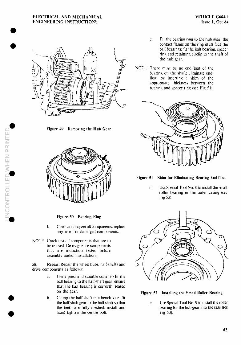
0 a
0
0
0 0
ELECTRICAL AND MECHANICAL VEHICLE C6041 ENGINEERING INSTRUCTIONS Issue 1. Ott 84
Figure 49 Removing the Hub Gear
Figure 50 Bearing Ring
k. Clean and inspect all components: replace any worn or damaged components.
NOTE Crack test all components that are to be re-used. De-magnetise components thar are induction tested before assembly and/or installation.
58. Repair. Repair the wheel hubs, half-shafts and drive components as follows:
a. Use a press and suitable collar to fit the ball bearing to the half-shaft gear: ensure that the ball bearing is correctly seated on the gear.
b. Clamp the half-shaft in a bench vice; fit the half-shaft gear to the half-shaft so that the teeth are fully meshed; install and hand tighten the centre bolt.
C. FII [he bearing rmg to the hub gear; the contact flange on the ring must face the ball bearings; fit the ball bearing. spacer ring and retainmg circlip to the shaft of the hub gear.
NOTE There must be no end-float of the bearing on the shaft; eliminate end- float by inserting a shim of the appropriate thickness between the bearmg and spacer ring (see Fig 5 I I.
Figure 51 Shim for Eliminating Bearing End-float
d. Use Special Tool No. 8 to install the small roller bearing in the outer casing isee Fig 52).
Figure 52 Installing the Small Roller Bearing
e. Use Special Tool No. 9 to install the roller bearing for the hub gear into the case (see Fig 53).
63
UN
CO
NT
RO
LLE
D W
HE
N P
RIN
TE
D

VEHICLE G6041 Issue 1. Ott 84
ELECTRICAL AND MECHANICAL ENGINEERING INSTRUCTIONS
Figure 53 Installing the Large Roller Bearing
59. Installation. Install the wheel hubs. half-shafts and drive components as follows:
a. Install the assembled half-shaft into the axle casing; a soft headed hammer may be used to drive the bearing and half-shaft fully home.
b. Screw Special Tool No. IO into the bearing ring in the hub gear (see Fig 54; fit the hub drive gear with the special tool to the hub inner casing.
Figure 51 Fitting Special Tool No. 10
C. Use Special Tool No. IO to draw the hub gear and bearing assembly evenly into the bearing seat (see Fig 55); remove the special tool and install and tighten the retaining bolts to 40 Nm.
Figure 55 Fitting the Hub Gear
d.
e.
f.
g.
h.
i.
i
k.
Differential
Lock up the final drive by inserting a soft round drift or punch between the cogs of the half-shaft gear and hub gear. Ensure that the constant-velocity joint shaft and half-shaft gear are totally engaged then tighten the centre bolt in the half-shaft gear to 600 Nm.
Screw Special Tool No. 5 into the top two holes in the wheel hub/axle casing; coat the parting surface of the outer casing with a suitable sealing compound; fit the outer casing to the wheel hub/axle casing, taking care not to dislodge the special tool holding the bearing rollers in place.
Install the retaining bolts and nuts around the casing rim and tighten to 200 Nm.
Fit the hub seal in the casing (refer to VEHICLE G603).
Fit the wear ring and oil baffle in the cas- ing (refer to VEHICLE G603).
Fit the wheel hub and brake disc (refer to VEHICLE G603).
Fit the brake calipers (refer to VEHICLE G603).
Fit the backplates; install and tighten the oil drain plugs; attach a NO OIL label to the axle casing and remove the axle from the cradle or trestle.
60. The differential is repaired as a separate com- ponent of the drive train. The differential consists of a number of separate components, which are shown in Figure 56. forming an assembly. The overhaul procedures are listed as follows:
0
0 l
63
UN
CO
NT
RO
LLE
D W
HE
N P
RIN
TE
D

ELECTRlCAL AND MECHANICAL ENGINEERING INSTRUCTIONS
VEHICLE (2604I Issue 1, Ott 84
0 0
a. removal (refer to para 611.
b. repair (refer to para 621,
C. adjustment (refer to para 631. and d. installatton (refer to para 64).
61. Removal. Remove the differential assembl>, as follows:
a. Remove the propeller shaft from the torque tube (if fitted).
NOTE For ease of handling and access to components, secure the axle and torque tube in a suitable cradle or trestle.
1. Half-shaft 11 Shim 2. Dog clutch 12. Half-shaft 3. Garner bearing 13. Exchange kit 4 Bolt 14 Thrust pad 5. Exchange kit 15. PInIon gear 6. Crownwheel 16. Long spider shaft 7. PInIon 17. Short spider shaft 8. Garner 18. Side gear 9 Locknut 19. Thrust nng
10 Carrier beanng 20. Spacer
21. Sealing ring 31 Sealing ring 22 Yoke nut 32. Pilot bearing 23 Sealing ring 33. Exchange kit 24 Tab washer 34 Air cylinder 25 Snap ring 35. Sealing ring 26 PInIon beanng 36. Piston 27. Crush ring 37. Plug 28 Sealing ring 38. Union gland 29 PinIon flange 39. Union screw 30 Shim 40 Air line
41. Bolt 42. 0-ring 43. Housing 44 0-ring 45 Beanng bush 46 Bearing joint 47 Clrclip 48 Shift fork 49. Thrust pad
Figure 56 Differential Assembly
65
UN
CO
NT
RO
LLE
D W
HE
N P
RIN
TE
D

VEHICLE G604I Issue 1, Ott 84
ELECTRICAL AND MECHANICAL ENGINEERING INSTRUCTIONS
b.
C.
d.
e.
f.
EL
h.
i.
j.
k.
Attach a wire rope or sling to an overhead lifting device; attach the free end of the sling to the torque tube at the gearbox end and raise the torque tube until it is vertical; do not lift the axle off the cradle or trestle. Remove the retaining bolts and nuts and remove the axle struts from the torque tube and axle casing: remove the brake lines, vent lines and air lines. Remove the parking brake cylinder (refer to VEHICLE G603). Remove the bolts securing the torque tube to the axle casing and using the overhead lifting device raise the torque tube until it is clear of the pinion shaft: move the torque tube to one side and lower it to the floor; remove the sling from the torque tube. Remove the brake calipers and brake discs (refer to VEHICLE G603). Remove the wheel hubs and half-shafts (refer to para 57). Attach the sling to one end of the axle so that when the axle is raised the bolts securing the two halves of the casing are uppermost; raise the axle until it is vertical. Loosen the bolts securing the two halves of the axle casing; remove the pinion assembly from the casing and remove the casing bolts; split the casing in half. Remove the crownwheel and differential from the axle casing. Remove the bolts (Fig 56. 41) securing the shift cylinder (34) for the differential lock to the axle casing and detach the
62. follows:
NOTE
cylinder from the casing; remove the shift-dog (2) from the axle casing.
I. Remove the circlip (47). from the shift- dog selector-fork 148) and remove the selector fork and the bearing joint (361 from the axle casing.
Repair. Repair the differential assembly as
I. Recause of the fine tolerances applicable to the differential assembly, the pinion and the differential are repaired as separate components before assembly into a complete working unit. However, if either the crown-wheel or the pinion are re- placed. both crown-wheel and pinion must be replaced as matched com- ponents. The numbers that are stamped into the crown-wheel and pinion must be identical (see Fig 57). 2. Repair the pinion assembly first. then repair the crown-wheel and dif- ferential assembly.
Figure 57 Crown Wheel and Pinion
a. Remove the snap ring (I 1. tab washer (3) and O-ring (3) from the yoke nut (3) on the pinion shaft (see Fig 58).
1 Snap ring 2. Tab washer 3 0-nng 4. Yoke nut 5. 011 seal 6. Spacer 7 PinIon bearing
Figure 58 Pinion Flange Assembly
8. Crush ring 9. Sealing nng
10. Pinion flange 1 1. Shim 12. Sealing ring 13. Pilot beanng 14 PInIon
l
l
a
l
66
UN
CO
NT
RO
LLE
D W
HE
N P
RIN
TE
D

ELECTRICAL AND MECHANICAL VEHICLE G604-1 ENGINEERING INSTRUCTIONS Issue 1, Ott 84
a l
b. Clamp Special Tool No. 1 I in a bench vice; fit a ring spanner of appropriate size to the yoke nut on the pinion shaft (see Fig 59).
Figure 59 Removing the Yoke Nut
0
0 0
C. Insert the pinion shaft into Special Tool No. 1 I so that the shaft is secure; unscrew the yoke nut until free of the threads on the shaft; remove the pinion assembly from Special Tool No. 1 I and remove the yoke nut from the shaft.
NOTE After removal, discard the crush ring (8). do not reuse.
d. Use a suitable press and blocks or collar to remove the pinion gear and shaft from the pinion flange; remove the shaft oil seal (51, crush ring (81, spacer (6). pinion bearing (7) and sealing ring (91 from the pinion flange (see Fig 591.
e. Use a suitable puller or soft drift and hammer to remove both bearing outer races from the pinion flange; use a suitable puller or press and collar to remove the pilot bearing (13) from the pinion shaft.
f. Use a suitable puller and collar to remove the carrier bearings from the differential carrier: remove the bolts securing the crown-wheel to the carrier and remove the crown-wheel.
I.5 Remove the dogged side-gear and thrust ring from the crown-wheel.
NOTE I. The pinion spider is not a solid k. Install the remaining thrust pads and unit. The spider consists of two pinion gears in the carrier with the two separate short shafts and one long short spider shafts, so that the spigots on shaft; spigots on both short shafts slot the shafts slot into the holes in the long into holes in the centre of the long spider shaft; use a soft headed hammer shaft, forming the spider unit. to drive the shafts fully home if necessary.
NOTE
NOTE
2. Take note of the orientation of the long shaft for later installation purposes.
h. Withdraw the two short spider shafts from the carrier; remove the thrust pads and two pinion gears from the carrier; remove the long spider shaft and the remaining thrust pads and pinion gears from the carrier; remove the remaining side gear and thrust ring from the carrier.
i. Clean and inspect all components: replace any components that are worn or damaged.
Pinion gears. thrust pads, thrust rings, side gears and spider shafts must be replaced as matched components in kit form and not as separate items.
.i. Lightly coat all components with clean OEP-220 oil; install the thrust ring and plain side-gear into the carrier; fit the two thrust pads. pinion gears and the long spider shaft to the carrier: ensure that the shaft is fitted correctly.
When installing the short spider shafts in the carrier, the recesses in the shafts must be aligned to accommodate the bolts securing the crown-wheel to the carrier (see Fig 60).
Figure 60 Installing the Short Spider Shafts
67
UN
CO
NT
RO
LLE
D W
HE
N P
RIN
TE
D
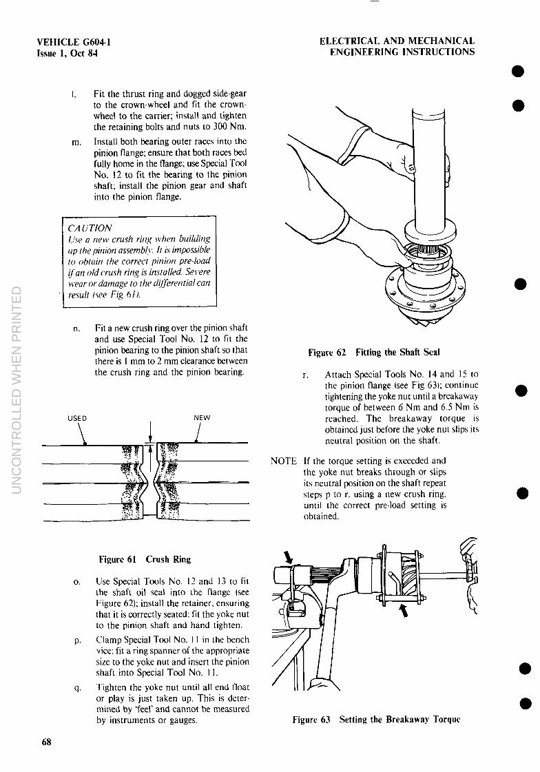
VEHICLE G604-1 Issue 1, Ott 84
ELECTRICAL AND MECHANICAL ENGINEERING INSTRUCTIONS
I. Fit the thrust ring and dogged side-gear to the crown-wheel and fit the crown- wheel to the carrier; install and tighten the retaining bolts and nuts to 300 Nm.
m. Install both bearing outer races into the pinion flange; ensure that both races bed fully home in the flange; use Special Tool No. 12 to fit the bearing to the pinion shaft; install the pinion gear and shaft into the pinion flange.
CA liTION Use a new crush ring when building up the pinion as~emb!\*. it is impossible to obtain the correct pinion pre-load fan old crush ring is installed. Serwe Iceat- or damage to the d(&erential can result /qee Fi.y 61).
n. Fit a new crush ring over the pinion shaft and use Special Tool No. 12 to fit the pinion bearing to the pinion shaft so that there is I mm to 2 mm clearance between the crush ring and the pinion bearing.
USED NEW
Figure 61 Crush Ring
0. Use Special Tools No. I2 and I3 to fit the shaft oil seal into the flange [see Figure 62); install the retainer. ensuring that it is correctly seated: fit the yoke nut to the pinion shaft and hand tighten.
P. Clamp Special Tool No. 11 in the bench vice; fit a ring spanner of the appropriate size to the yoke nut and insert the pinion shaft into Special Tool No. I I.
(2. Tighten the yoke nut until all end float or play is just taken up. This is deter- mined by ‘feel’ and cannot be measured by instruments or gauges.
Figure 62 Fitting the Shaft Seal
r. Attach Special Tools No. I3 and I5 to the pinion flange (see Fig 63,; continue tightening the yoke nut until a breakaway torque of between 6 Nm and 6.5 Nm is reached. The breakaway torque is obtained just before the yoke nut slips its neutral position on the shaft.
NOTE If the torque setting is exceeded and the yoke nut breaks through or slips its neutral position on the shaft repeat steps p to r. using a new crush ring, until the correct pre-load setting is obtained.
Figure 63 Setting the Breakaway Torque
0 0
l
68
UN
CO
NT
RO
LLE
D W
HE
N P
RIN
TE
D

0
0
0
ELECTRICAL AND MECHANICAL ENGINEERING INSTRUCTIONS
S. Fit the sealing ring. tab washer and snap ring to the yoke nut on the pinion shaft.
63. Adjustment. Determine S I shim thickness from sub-para g. Adjust the differential backlash and gear meshing pattern as follows (see Fig 64):
a. Install the outer race for the smaller carrier bearing into the axle casing half: ensure that the bearing race is bedded fully home in the casing.
b. Press the small carrier bearing into the carrier to half the width of the bearing.
C. Install the differential assembly into the axle casing; join the two half casings together and install and hand tighten the casing bolts.
d. install the pinion assembly; tighten the casing bolts to 200 Nm. in a diagonal sequence, whilst steadily rotating the crown-wheel and pinion.
e. Remove the pinion assembly from the casing.
f. Remove the casing bolts and split the casing; remove the differential assembly taking extreme care not to disturb the position of the carrier bearings.
is. Obtain the shim thickness measurement as follows:
(1 I The shim thickness SI for the larger taper bearing on the differential lock side. determines backlash and tooth meshing pattern. in conjunction with shim thickness S3.
Example: SI =J - (B+C)
J = 129.36 - (B + Cl = 127.95
SI = I.41 mm
(2) Shim thickness for the smaller taper bearing
Example: S2 = H + I H = 1.40
+ I = 0.20 (pre-load constant)
S2 = I.60 mm
(3) The shim thickness S3 for the flange of the pinion assembly determines the depth by which the pinion engages in the crown-wheel.
h.
i.
j.
k.
VEHICLE G604-1 Issue 1, Ott 84
Example: S3 = iF+G) - E
(F+GI = 194.80 -E = 193.03
S3 = 1.77 mm
Use a feeler gauge to measure gap H and add 0.2 mm to the reading to determine the shim thickness for the correct pre-load.
Remove the outer race for the smaller bearing, fit the correct shim and install the outer race; ensure that the bearing race and shim are fully bedded in the casing.
Use a soft drift and hammer to drive the smaller bearing fully home onto the differential carrier.
Check the meshing pattern of the crown- wheel and pinion, and assemble the unit referring to para 62.
64. Installation. Install the differential assembly as follows:
a.
b.
C.
d.
e.
f.
Install the bearing outer races, with shims of the required thickness. into the axle casing; ensure that the shims and races are correctly seated in the casing halves.
Install the shift dog and the selector fork for the shift dog in the axle casing.
Fit the swivel joint into the axle casing and drive it into the correct position; install the snap ring to secure the selec- tor fork in position.
Fit the shift cylinder for the differential lock; install and tighten the retaining bolts.
Install the differential in the axle casing at the lock side; coat the parting surfaces of the casing with a suitable sealing compound.
Join the two halves of the axle casing together; install and hand tighten the casing bolts; coat the parting surfaces of the pinion flange and axle casing with a suitable sealing compound.
NOTE The pilot end of the pinion flange has two oil channels drilled into the housing. Install the pinion assembly so that the oil channels are uppermost when the axle is fitted to a truck.
69
UN
CO
NT
RO
LLE
D W
HE
N P
RIN
TE
D

VEHICLE G604-1 ELECTRICAL AND MECHANICAL Issue 1, Ott 84 ENGINEERING INSTRUCTIONS
g.
h.
i.
j.
k.
I.
m.
n.
Fit the pinion assembly, with the necessary shim(s), to the axle casing; tighten the axle casing bolts. in a diagonal sequence. to 200 Nm.
Coat the outer surface of the pinion flange with a suitable seating compound; rotate the axle casing into position so that the torque tube can be fitted.
Fit a sling to an overhead lifting device; attach the free end of the sling to the torque tube at the gearbox end and raise the torque tube until it can be fitted to the axle casing.
Position the torque tube on the axle casing; install the retaining bolts and tighten to 200 Nm.
Coat the splines of the propeller shaft sliding joint with XC276 molybdenum- disulphide grease; install the propeller shaft in the torque tube.
Attach the axle struts to the torque tube and axle casing; install and tighten the retaining bolts and nuts to 350 Nm; lower the torque tube until it is in the horizontal position.
Fit the brake actuating cylinder to the axle casing; adjust the piston rod travel (refer to VEHICLE G603); fit and tighten all brake lines, vent lines and air lines.
Attach a NO OlL label to the axle casing and remove the assembly from the cradle or trestle.
FRONT AXLE
65. This section contains the repair procedures and specifications for the front axle. The components that make up the front axle assembly are shown in Figure 65 and are listed in component groups as follows:
a. steering knuckle bearings (refer to para 661,
b. wheel hubs and half-shafts (refer to para 691, and
C. differential (refer to para 70).
NOTE I. Crack test all compoilents that are to be re-used. Demagnetise com- ponents that are induction tested before assembly and/or installation.
’ -. The half-shafts and C.V. joints are an integral unit and cannot be repaired. If the half-shafts and C.V. joints show signs of damage. wear or
torsional fatigue they must be replaced.
3. Read NOTE: I to 5 in para 55 before proceeding.
Steering Knuckle Bearings
66. The steering knuckle bearings are repaired as separate components of the wheel hub assembly. The relevant procedures are as follows:
a. removal (refer to para 671, and
b. installation (refer to para 68).
67. Removal. Remove the steering knuckle bearings as follows:
NOTE For ease of handling and access to components, secure the axle assembly in a suitable cradle or trestle.
a.
b.
C.
d.
e.
f.
g.
h.
i.
j.
k.
I.
m.
Remove the track-rod and drag link if attached (refer to VEHICLE G603).
Remove the drain plugs and allow all oil to drain from the wheel hubs:
Remove the brake calipers (refer to VEHICLE G603).
Remove the brake disc and wheel hub (refer to VEHICLE G6031.
Remove the oil baffle and wear ring l,refer to VEHlCLE G603).
Remove the wheel hub casing, half-shaft gear and hub gear (refer to para 57 e. to h.t.
Remove the retaining bolts and detach the cover over the upper swivel joint on the steering knuckle; use Special Tool No. I6 to remove the swivel joint bush from the upper pivot pin (see Fig 661.
Remove the bolts securing the steering arm to the steering knuckle.
Remove the steering arm, saddle, bearing caps. bearing shells. thrust washer and thrust pad.
Remove the O-ring from the pivot arm of the steering knuckle.
Remove the constant-velocity joint shaft.
Remove the bearing assembly from the lower pivot pin.
Clean and inspect all components: replace any worn or damaged components.
l
l
a
70
UN
CO
NT
RO
LLE
D W
HE
N P
RIN
TE
D

0 0
0
0
Dimension A : etched in the centre axle casing at the differential lock side - I. (e.g. 46.04)
Dimension B : etched in the crownwheel - 2. (e.g. 95.95 mml
Dimension C : overall width of the large carrier bearing, measured in situ (e.g. 32.00 mm)
Dimension D : etched in the centre of the axle casing - 3 production measure- ment (e.g. 135.78 mm)
Dimension E : etched in the centre of the axle casing at the differential lock side - 4 (e.g. 193.03 mm)
Dimension F : measurement from the end face of the pinion to the contact sur- face of the centre of the axle casing - measurement to be deter- mined using a depth gauge (e.g. IO I .60 mm)
Dimension G : etched in the end face of the drive pinion - 5 (e.g. 93.20 mm)
Dimension H : measurement from the carrier bearing outer race to the bearing contact surface on the carrier (e.g. 1.40 mm)
Dimension 1 : pre-load constant - 0.20 mm
Dimension J : etched in the cenrre of the axle casing at the differential lock side - 6 (e.g. 129.36 mm)
NOTE As all values differ from axle to axle, the dimensions shown in this illustration are examples only. The dimensions which are etched into the axle casing must be used when setting the gear meshing pattern for the crownwheel and pinion.
6
4
“1” -J
D--83.51-+-
1
E
Figure 64 Adjostiung Dimensions - hwk rant-! IDifferePnPial
UN
CO
NT
RO
LLE
D W
HE
N P
RIN
TE
D

ELECTRICAL AND MECHANICAL ENGINEERING INSTRUCTIONS
VEHICLE (X04-1 Issue 1, Ott 84
1. Brake caliper B Drive pinion 2. Wheel hub 9 Torque tube 3. Half-shaft gear 10 Torque ball casing 4 Upper swivel joint 11 Half-shaft 5 Axle tube 12 C V Joint 6. Dlfferentlal-lock mechanism 13 Lower swivel joint 7. Dlfferentlal assembly 14 Hub gear
Figure 65 Front Axle Assembly
68. Installation. Install the steering knuchle bearing as follows:
a.
b.
C.
d.
Figure 66 Removing the Upper Swivel Joint Bush
Install the constant-velocity joint shaft. Coat the swivel pins and all bearing com- I>onents with XC-387 grease containing an extreme pressure additive (EP - Series 31.
Fit the inner seal O-ring (I) to the lower needle bearing (2) and install the complete unit (see Fig 67).
Ftt the bearing shell. thrust washer. thrust pad and bearing cap to the lower pivot pin; fit the O-ring in the bearing cap.
Fit the 0-rmg to the upper pivot pin and fit the bearing shell to the pivot pin. The extraction groove (1 j of the swivel joint
73
UN
CO
NT
RO
LLE
D W
HE
N P
RIN
TE
D

VEHICLE G6041 ELECTRICAL AND MECHANICAL Issue 1, Ott 84 ENGINEERING INSTRUCTIONS
must point upwards tsee Fig 68) and the recess on the outer race must point in the direction of the travel.
g.
h.
1. Seal nng 2 Needle bearing
Figure 67 Lower Pivot Pin Assembly j.
depth between the installed spacer ring and the contact surface of the steering knuckle; make a note of the gauge reading (see Fig 691.
Measure the depth of the groove in the end plate (see Fig 69); the difference between the two measurements, plus the permissible pre-load factor 10.2 mm to 0.3 mm), determines the thickness of the shim(s) to be installed.
Install a shim(s) of the correct thickness into the steering knuckle; fit the bearing saddle and steering arm into position on the steering knuckle; install and hand tighten the retaining bolts.
Fit the end plate in position over the upper pivot pin; install and tighten the retaining bolts; tighten the retaining bolts for the bearing saddle and steering arm to 400 Nm.
Install the hub gear, half-shaft gear and wheel hub casing (refer to para 59 b. to f.).
I. ExtractIon groove 2. Recess
Figure 68 Upper Pivot Pin Assembly
e. Hook the steering knuckle on the axle k. casing, over the upper pivot pin: install the bearing cap, spacer ring and O-ring.
I. NOTE No weight must bear on the axle or
upper pivot pin when taking measurements to determine shim thickness for pre-load.
m.
f. Support the steering knuckle assembly and, using a depth gauge, measure the
t-i.
l
0
0
Fit the hub seal in the casing (refer to VEHICLE G603).
Fit the wear ring and oil baffle into position in the casing [refer to VEHICLE G603).
Fit the wheel hub and brake disc (refer to VEHICLE C603.)
Fit the brake calipers lrefer to VEHlCLE G603). l
UN
CO
NT
RO
LLE
D W
HE
N P
RIN
TE
D

ELECTRICAL AND MECHAIVICAL ENGINEERING INSTRUCTIONS
VEHICLE G604-1 Issue 1, Ott 84
Figure 69 Pre-load (shim, Measurements
0. Fit the backplates: install and tighten the 011 dram plugs: fit the track rod and drag link if these items were orlglnally removed from the axle assembly (refer to VEHICLE G603).
P. Attach a NO OIL label to the alle casing and remove the axle from the cradle or trestle.
Wheel Hubs and Half Shafts
69. The wheel hubs with the flnal-drike com- ponents and half-shafts for the front wheel drive can be overhauled separately. The relevant procedures are as for the rear axle [refer to para 561.
Differential
70. The differenttal is repaired as a separate com- ponent of the drive train. The dtfferentlal consists of a number of separate components froming an assembly. and the overhaul procedures are as for the rear axle (refer to para 601.
BRAKE SYSTEM
71. This section contams the repair procedures and specification tables for the brake system. The relevant procedures are as follows:
a.
b.
C.
d.
e.
f.
iIT
h
i.
i
air compressor (refer to para 73).
tandem master cylmder (refer to para 761.
front brake calipers (refer to para 791.
rear brake calipers (refer to para 821.
four ctrcutt protection valve (Bosch) Irefer to para 851.
trailer brake (stretch) valve IWabco) (refer to para 891.
pneumatic master cylinder IWabcol [refer to para 931
shift cylinder lWabcol [refer to para 97).
handbrake valve tWabcol (refer to para 971.
parking brake cylinder (Wabco) [refer to para 105).
75
UN
CO
NT
RO
LLE
D W
HE
N P
RIN
TE
D

VEHICLE G604-1 Issue 1, Ott 83
ELECTRICAL AND MECHANICAL ENGINEERING INSTRUCTIONS
k.
I.
m.
n.
0.
P.
9,
r.
S.
t.
U.
v.
ALB valve (Wabco) (refer to para 109),
footbrake valve (Wabco) (refer to paral 13),
four-circuit protection valve IWabco) (refer to para I l7),
trailer brake control valve (Wabco) (refer to para 121).
engine brake valve (Bosch) (refer to para 1251.
pressure limiting valve. brake circuit (Bosch) (refer to para 1191.
dual-pressure pressure limiting valve (Bosch1 (refer to para 133).
footbrake valve (Bosch) (refer to para 137).
pressure regulator (Bosch) (refer to para 1411,
handbrake valve (Bosch) (refer to para 1431,
engine brake cylinder (Knorr) (refer to para 145), and
pressurisation and venting valve (Wabco) (refer to para 149).
Brake System Repair Guide.
72. The following Points should be noted during repair:
a. As most control valves have internal components under spring tension, take particular care when removing covers and/or retaining circlips or snap rings. As components could release with explosive force and cause injury. never use hands to try and catch or hold these com- ponents. Use suitable clamping or fixing jigs to hold and gradually release com- ponents under spring tension.
b. Use only methylated spirits or recom- mended cleaning agents to clean the com- ponents and valve housings. Do not use Carbon Tetrachloride or other degreasing agents.
C. Always renew sealing elements. O-rings and rubber cups. Lubricate these com- ponents with rubber grease prior to insrallation. Always renew gaskets.
d.
e.
f.
g.
h.
Air Compressor
It is particularly important to inspect sealing areas and valve seats in the valve bodies and dual piston assemblies. where applicable. Should score marks, gouges. scratches or signs of excessive wear be evident. renew the valve.
To avoid damaging the valve bodies in vice jaws and to facilitate easy handling and access to components, the manufac- turer recommends the use of special clamping devices: these special tools are shown in Figure 70 and Figure 7 I.
Never attempt to hone the bores in aluminium valve bodies, as the sealing or working surface is specially treated against wear. and honing destroys the surface.
Always scribe or match mark the position of end covers and ancilliary components in relation to the main body, for later assembly purposes. Take particular note of the order in which the components of a valve come apart.
Do not use screwdrivers or similar sharp instruments to remove rubber parts from grooves; use only probes with smoorh. rounded and flat tips.
73. Fig 72):
NOTE
Repair the air compressor as follows (see
a. dismantling lrefer to para 74). and
b. assembly (refer to para 75).
I. Because of the diversity and com- plexity of the various machining processes involved in overhauling the compressor. no machining procedures have been detailed. Carry out the machining work using standard machine shop practices and processes.
’ The technician must determine A. what work is required on the compressor.
3. Failure to ensure the correct clearances and tolerances applicable to the piston and piston rings will result in ring-scuffing. excessive blow-by, ring breakage and severe wear of the barrel.
l
a
a a
76
UN
CO
NT
RO
LLE
D W
HE
N P
RIN
TE
D

ELECTRICAL AND MECHANICAL VEHICLE G604-1 ENGINEERING INSTRUCTIONS Issue I, Ott 84
Bl
B3 \ (/J \ 899-709-072-4
B5
B2
899-709-096.4
899-709-035-2
Figure 70 Wabco Special Tools (Sheet 1)
77
UN
CO
NT
RO
LLE
D W
HE
N P
RIN
TE
D

VEHICLE G604-1 Issue I, Ott 84
B7
ELECTRJCAL AND MECHANJCAL ENGINEERING INSTRUCTIONS
899-709-100-0
Figure 70 Wabco Special Tools (Sheet 2)
B8
1 o-681-269-012 2. o-681-248-010
Figure 71 Bosch Special Tools
l UN
CO
NT
RO
LLE
D W
HE
N P
RIN
TE
D

ELECTRICAL AND MECHANICAL ENGINEERING INSTRUCTIONS
VEHICLE G604-1 Issue I, Ott 84
3. Check the connecting rod for nicks or gouges in the metal which could lead to fatigue and eventual rod failure. In cases of doubt. replace the connecting rod.
5, The barrel and piston must be replaced as matched components. New piston rings, obtainable in kits, may be installed on used pistons at the discretion of the technician.
6. The compressor is one of the primary components of the brake system and a high standard of cleanliness is essential when carrying out repairs. The compressor can be severly damaged by dirt or dust in the working parts.
7. The technician must determine whether the barrel bore requires honing. If the barrel bore is honed. fit new rings to the piston.
8. Do not use caustic or acid based cleaning products. Use only recom- mended cleaning agents or solvents to clean the compressor.
74. Dismantling. Dismantle the air compressor as follows (see Fig 72):
a. Remove the cylinder head bolts (2) and remove the cylinder head (3) from the barrel; detach and remove the valve plate (7) from the barrel: remove and discard the gaskets (4 or 5, 9 or 101.
b. Remove the locknuts (12) securing the barrel I 161 to the crankcase (3 I); remove the barrel by lifting it upwards and sliding it over the piston ( 181; remove and discard the barrel base flange gasket (251.
C. Remove the circlips (20) that secure the gudgeon pin (2 I I in position in the piston: press the gudgeon pin out of the piston until the piston can be removed from the connecting rod (22).
NOTE Before removing the connecting rod note the orientation of the connecting rod in relation to the crankshaft.
d. Remove the big-end cap bolts (231; remove the connecting rod: remove and discard the big-end bearing shells (331 from the connecting rod and big-end cap.
e. Remove the bolts 128) securing the bearing plate (30) to the crankcase and remove the bearing plate.
f. Wlthdraw the crankshaft from the crankcase: use an internal bearing puller to remove the bearing from the bearing plate.
g. Remove and discard the crankshaft O- ring (26) from the bearing plate; remove and discard the sealing ring (29t from the outer flange of the bearing plate.
NOTE The crankshaft roller bearing is a shrink fit on the crankshaft.
h. Remove the nut (37) and washer from the crankshaft spigot; remove the oil seal (35).
i. Use a long reach puller to remove the bearing (34) from the crankshaft.
.i. Inspect the crankshaft bearing bush m the bearing seat; replace the bush If it is damaged or worn.
k. Clean and inspect all components; replace components that are worn or damaged.
NOTE Lightly coat all components with clean OMD-I I5 oil. Protect those com- ponents not immediately required by covering them with a clean, oil soaked cloth.
75. Assembly. Assemble the air compressor as follows (see Fig 721:
a.
b.
C.
d.
e.
f.
Clamp the crankcase in a bench vice with the barrel parting surface uppermost: install the crankshaft roller bearing in the bearing plate. Install the cranhshaft O-ring (26) into the bearing plate (301; fit the sealing ring (29) to the outer flange on the bearing plate. Heat the crankshaft bearing (34) to approximately 8OoC. using oil bath or oven heating techniques.
Fit the bearing to the crankshaft; ensure that the bearing race seats fully against the buttress collar on the crankshaft: allow the assembly to air cool to ambient temperature; fit the oil seal (351, spring washer (36) and nut (371 to the crankshaft. Install the crankshaft into the crankcase; centre the crankshaft and fit the bearing plate to the crankcase; Install and tighten the retaining bolts (281; rotate the crankshaft a few times by hand to check for free movement. Fit the bearing shells 133) to the big-end cap and connecting rod big-end: ensure
79
UN
CO
NT
RO
LLE
D W
HE
N P
RIN
TE
D

VEHICLE G6041 Issue 1, Ott 84
ELECTRICAL AND MECHANICAL ENGINEERING INSTRUCTIONS
i%
h.
i.
j.
k.
I.
m.
Il.
0.
that the lugs on the bearing shells slot into the recesses in the big-end cap and connecting rod.
Rotate the crankshaft into position so that the big-end cap can be installed; install the big-end cap over the crankshaft; fit the connecting rod, ensuring that it is correctly orientated and that the big-end cap and connecting rod are number matched.
Install the big-end cap bolts (23) and tighten to 30 Nm; hold the connecting rod and rotate the crankshaft a few times by hand to check for free movement.
Position the piston over the connecting rod small-end so that the gudgeon pin can be inserted; using a steady, even pressure. press the gudgeon pin (21) through the piston and small-end bearing 139); install the retaining circlips (20) to secure the gudgeon pin in position.
Fit the barrel base-flange gasket (25) to the crankcase.
Rotate the crankshaft until the piston is at T.D.C. and lock the piston in this position by inserting a wooden wedge or block between the piston skirt and crankcase/barrel parting surface.
Compress the piston rings, slide the barrel over the piston and lower it until the bottom piston ring is inslde the barrel. Remove the ring compressor and lower the barrel onto the crankcase: install and tighten the locknuts to 30 Nm.
Fit the gasket (9 or IO) for the valve plate (7) to the barrel. then fit the valve plate to the barrel; fit the gasket (4 or 5) for the cylinder head to the valve plate.
Position the cylinder head (3) correctly over the valve plate on the barrel; install and tighten the cylinder head bolts (7) to 35 Nm.
With the compressor running at a speed of 2600 r.p.m. check that the air delivery is 100 litreslmin. and that the cut-out pressure is 18.5 bar & 0.5 bar.
Tandem Master Cylinder
76. Repalr the tandem master cylinder as follows.
a. dismantling (refer to para 771. and
b. assembly (refer to para 781.
NOTE I. Never increase the size of the master cylinder bore by more than 0.017 mm oversize of the nominal diameter 3 I .75 mm. Replace the cylinder if scratches. scoring or pit marks remain in the bore sealing area after honing.
’ -. When honing the master cylinder. a lubricant such as brake fluid must be used. Remove all traces of the fluid after honing
77. Dismantling. Dismantle the brake cylinder as follows (see Fig 731:
NOTE To facilitate easy handling and access to components in the master cylinder. the manufacturer recommends the construction of a holdinglflxing jig as illustrated in Figure 74. The Jig also obviates possible damage to the cylinder from bench-vice jaws.
l
a
master
a. Fix the master cylinder m a suitable holding/fixing jig, and clamp the jig in 3 bench vice.
b. Remove the circlip (I 1 and strike plate 121 from the flanged end of the master cylinder; the spring I 131 pushes out [he primary piston assembly: remove the assembly.
C. Remove the screw plug 171. $531 161 and strike plate r51.
d. Use a wooden or soft drift and with a steady even pressure push the remaining
80
UN
CO
NT
RO
LLE
D W
HE
N P
RIN
TE
D

ELECTRICAL AND MECHANKAL VEHPCLIE C604-% ENGHNEERING PNSTRUCTHONS Essue I, Ott 84
1 2 3 4 5 6. 7 8 9
10 11 12 13. 14. 15 16 17 18 19. 20 21 22 23 24 25 26 27 28 29 30 31 32 33 34 35 36 37 38 39
Air compressor unit Bolt Cvllnder head Gasket Gasket (alternatIve) Discharge valve Valve plate Inlet valve Gasket Gasket IalternatIve) Snap ring Bolt Spnng washer Secunng bracket Exchange kit Barrel Compresslon rungs Piston 011 control ring Clrcllps Gudgeon pin Connecting rod Big end cap bolt Locknut Gasket 0-ring Spring washer Bolt Sealing nng Bearing plate Crankcase Crankshaft Big-end bearings Ball beartng 011 seal Sprtng washer Retalnlng nut Sealing ring - alumlnlum Small-end beanng
-I-’ s?+
Q
-18
23
v-12
I 11 13
I
14
.-- /--- J /-'
y-15
Figure 72 Air Compressor hsemblg
UN
CO
NT
RO
LLE
D W
HE
N P
RIN
TE
D

0
ELECTRICAL AND MECHANICAL ENGINEERING INSTRUCTIONS
VEHICLE G6041 Issue I, Ott 84
1 2 3 4 5 67
14 ii lb 9 13 12 11 10 9 a
1. Cltcllp 6 Seal 11 Piston cup 2 Strike plate 7 Screw plug 12 Piston cups 3. Primary piston 8 Secondary piston spring 13. Prlmarv piston spring 4 Secondary piston 9 Clrcllp 14. Piston 5 Strike plate 10 Spring plate
STUD Ml0 * 20
-20
T ’ /
d
7
D , , /
I _ / /
/
’ ,’ I’
’ ,
_i
-15,
Figure 73 Tandem Master Cylinder
-
1
y 825
Figure 74 Mounting Jig for Tandem Master Cylinder
83
UN
CO
NT
RO
LLE
D W
HE
N P
RIN
TE
D

VEHICLE G604-1 ELECTRICAL AND MECHANICAL Issue 1, Ott 84 ENGINEERING INSTRUCTIONS
NOTE
NOTE
78.
internal components out of the master cylinder in the direction of the mounting flange.
e. Remove the fluid reservoirs from the master cylinder.
Inspect all seals and cups from the master cylinder. Any scoring, nicks or gouges on the seals or cups indicate burrs or some other fault in the cylinder bore which must be rectified.
f. Remove all seals and cups from the primary and secondary piston; clean and inspect all components. Examine the interior of the cylinder, checking for burrs, gouges, scoring or scratches.
is. Use an internal measuring devtce to measure the cylinder bore; measure the bore along the sealing surfaces of the primary and secondary pistons. across the bore diameter and at two other points. approximately 90” apart.
h. Measure the cylinder bore for taper and concentricity; replace the master cylinder if out of limits (refer to Table 18).
Use standard workshop practices and procedures to hone the cylinder bore. Use fine water paper or emery cloth of 100 grit or finer to polish the bore. Clean the master cylinder. ensuring that all residue and lubricant from the honing process is removed.
i. Measure the cylinder bore again, using the same procedures detailed in sub-paras g and h.
Assembly. Assemble the brake master cylinder as follows (see Fig 73):
NOTE Wherever possible. fit the cups and seals onto the primary and secondary
I Cylinder
Diameter (mm1
34.91 38.10 41.27 -12.86 44.45
NOTE
pistons by hand. Do not use sharp instruments as these damage the cups and seals, leading to eventual brake failure.
Lubricate the bore of the master cylinder with clean brake fluid OStAustj8.
Lubricate all seals and cups with clean rubber grease.
Fit the seals and cups to the primary and secondary pistons: ensure that the cups and seals are fitted facmg in the correct direction.
Install the strike plate 121 and circlip t I I in the mounting flange side of the cylinder; ensure that the circlip seats correctly in the groove.
Do not force the pistons into the master cylinder: tight fitting pistons are an indication of trapped or squeezed cups and seals. which will have to be removed and renewed.
e.
f.
h.
i.
Install the primary piston (31 in the master cylinder. pushing it fully home against the striker.
Install the primary piston spring (131, ensuring that the spring fits over the valve spigot on the primary piston.
Install the secondary piston 14); ensuring that the peg on the end of the piston fits into the primary piston spring.
Install the secondary piston spring (8) so that it fits over the valve spigot on the secondary piston; press the piston and spring into the cylinder.
Ftt the strike plate 151; fit a new copper sealing washer (61 to the screw plug 171: fit and tighten the screw plug to between 17 Nm and 21 Nm.
Table 18 Master Cylinder Tolerances
Housmg Piston
Maxtmum diameter Smallest diameter (mm1 (mm)
35.01 3-1.75 38.15 37.93 -Il.36 -11.10 42.55 42.65 44.54 44.28
Maxtmum play (mm1
0.26 0.26 0.26 0.26 0.26
l
0
l
a a
84
UN
CO
NT
RO
LLE
D W
HE
N P
RIN
TE
D

0 0
0
0
ELECTRICAL AND MECHANICAL VEHICLE (3604-l ENGINEERING INSTRUCTIONS Issue I, Ott 84
j. Ftt the fluid reservoirs to the master cylinder: bench test the operation of the master cylinder in accordance with current workshop instructions.
Front Brake Calipers
79. Repair the front brake calipers as follows:
a. dismantling (refer to para 801, and b. assembly (refer to para 8 I ).
NOTE I. If the rubber boots in the calipers are hard. brittle or crached. they must be renewed.
7 -. Calipers with scored or corroded bores and corroded or damaged pistons must be scrapped. Under no circumstances reuse corroded or damaged calipers and pistons.
3. The stepped sections in the pistons must face outwards and towards the upper sections of the calipers.
Figure 75 Clamping the Pistons
using the same procedure used for the small pistons,
80. Dismantling. Dismantle the brake calipers as follows:
f.
g.
a. Remove the brake pads from the calipers (refer to VEHICLE G604: remove the rubber boots.
Remove and discard the square-section O- rings from the piston bores.
Clean the caliper and all components to be used during assembly; remove the bleeder screw and. using a wire probe of the appropriate diameter. clean the bleeder holes; use compressed air to blow any dirt or fluid from the channels.
NOTE The removal procedure requires the use of Special Tool No. 17. a G-clamp of suttable size and a piece of metal plate about 5 mm thick and large enough to cover the bore of the large diameter pistons.
81. Assembly. Assemble the brake calipers as follows:
a. Install and tighten the bleeder screw to I4 Nm.
b.
b. Fit Special Tool No. I7 Into the caliper so that the large pistons are held in place (see Fig 751: position the metal plate over one of the smaller pistons and secure it using the G-clamp.
Coat the square-section O-rings with rubber grease and install them in the appropriate grooves in the piston bores; ensure that the O-rings are not twisted in the grooves.
C.
C. Place a ptece of wood about IO mm thick into the caliper between both sets of pistons; ensure that the bleed screw is fully closed and, using compressed air. blow the free piston out of its bore.
d. Remove the G-clamp and plate: move the plate into place over the empty piston bore and secure it with the G-clamp: repeat the steps detailed in IdI to remove the other piston. remove the special tool. G-clamp and plate.
Lubricate the piston bores with clean brake tluid OX(Aust)8; match the pistons to their respective bores and. using a steady firm pressure. push the pistons in- to the bores.
d.
e.
Fit Special Tools No. I8 or I9 to Special Tool No. 17 with Special Tool No. 20 and use the assembled tool to install the rubber boots and dust caps. Fit the brake pads to the calipers (refer to VEHICLE (2603).
e. Place the special tool mto the caliper so that the two small piston bores are blocked off; place the metal plate over one of the large pistons and clamp it with the G-clamp. Remove the large pistons
Rear Brake Calipers
82. Repair the rear brabe calipers as follows:
a. Dlsmantlmg (refer to para 83). and b. assembly (refer to para 84.
85
UN
CO
NT
RO
LLE
D W
HE
N P
RIN
TE
D

ELECTRICAL AND MECHANICAL ENGINEERING INSTRUCTIONS
VEHICLE G604-I Issue 1. Ott 84
NOTE 1. If the rubber boots in the calipers are hard, brittle or cracked, they must be renewed.
? -. Calipers with scored or corroded bores and corroded or damaged pistons must be scrapped. Under no circumstances are corroded or damaged calipers and pistons to be re-used.
3. The stepped sections in the pistons must face outwards, and towards the upper sections of the calipers.
83. Dismantling. Dismantle the brake calipers as follows:
NOTE
a. Remove the brake pads from the calipers (refer to VEHICLE G604).
The removal procedure requires the use of Special Tool No. 17, a G-clamp of suitable size and a piece of metal plate about 5 mm thick and large enough to cover the bore of the large diameter pistons.
b. Fit Special Tool No. 17 into the caliper so that the large pistons are held in place: position the metal plate over one of the smaller pistons and secure it using the G-clamp.
C. Place a piece of wood about IO mm thick into the caliper between both sets of pistons; ensure that the bleed screw is fully closed and. using compressed air, blow the free piston out of its bore.
d. Remove the G-clamp and plate; move the plate into place over the empty piston bore and secure it with the G-clamp; repeat the steps detailed in (cl to remove the other piston: remove the special tool, G-clamp and metal plate.
e. Remove the hollow shaft setscrew covering the adjusting screw for the inner pistons. Using an allen key, turn the adjusting screw clockwise until the piston is far enough out of the bore to be removed by hand; remove the piston and remove the adjusting screw from the caliper: discard the O-ring.
f. Remove the locknut from the adjusting screw for the outer pistons; using an allen hey. turn the adjusting screw counterclockwise until the piston is far enough out of the bore to be removed by
NOTE
84. follows
hand; remove the piston and remove the adjusting screw from the caliper: discard the O-ring.
If difficulty is experienced in removing the pistons by means of the adjusting screws, use compressed air to remove the pistons. using the same procedure as for the smaller pistons.
g.
h.
i.
j.
k.
I.
Remove the bleeder screw from the calipers.
Slacken the locknut securing the parkmg brake mechanism to the caliper; remove the mechanism by unscrewing it from the caliper.
Withdraw the drive spindle and com- pression spring from the caliper; remove and discard the O-ring from the drive spindle.
Remove and discard the square-section O- ring from the grooves in the piston bores.
Remove and discard the O-ring from the locknut on the parking brake mechanism.
Clean the caliper and all components to be used during assembly; use a wire probe of appropriate diameter to clean the bleeder holes; use compressed air to blow any dirt or fluid from the channels.
Assembly. Assemble the brake calipers as
a.
b.
C.
d.
e.
Install and tighten the bleeder screw to l-l Nm.
Coat the square-section O-rings with rubber grease and install them in the appropriate grooves in the piston bores: ensure that the O-rings are not twisted in the grooves.
Fit a new O-ring to the drive spindle: install the compression spring and drive spindle into the caliper.
Fit a new O-ring to the lochnut on the parking brake mechanism; move the nut towards the mechanism housing as far as it will go.
Screw the parking brake mechamsm into the caliper as far as It will go: adjust the mechanism by unscrewing it - maximum is one complete turn outwards - until the actuating lever on the mechanism is on the same side and parallel with the bleeder screw; tighten the locknut to between I50 Nm and 180 Nm.
l
l
l
86
UN
CO
NT
RO
LLE
D W
HE
N P
RIN
TE
D
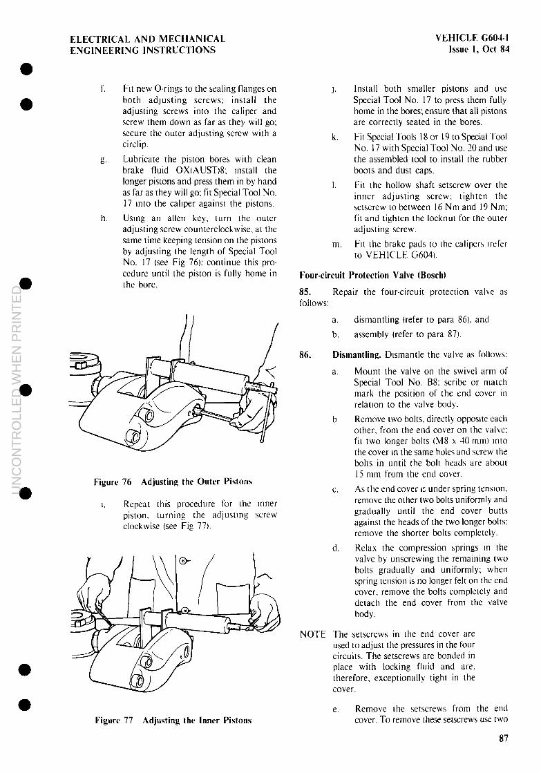
ELECTRICAL AND MECHANICAL VEHICLE G604-I ENGINEERING INSTRUCTIONS Issue 1, Ott 84
I”. Fit new O-rings to the sealing flanges on both adjusting screws; install the adjusting screws into the caliper and screw them down as far as they will go; secure the outer adjusting screw with a circlip.
k? Lubricate the piston bores with clean brake fluid OX(AUST)8; Install the longer pistons and press them in by hand as far as they will go; fit Special Tool No. I7 mto the cahper against the pistons.
h. Usmg an allen key. turn the outer adjusting screw counterclochwise. at the same time keeping tension on the pistons by adjusting the length of Special Tool No. I7 (see Fig 761; continue this pro- cedure until the piston is fully home in the bore.
Figure 76 Adjusting the Outer Pistons
I. Repeat this procedure for the Inner piston. turning the adjusting screw clockwise (see Fig 771.
k.
Install both smaller pistons and use Special Tool No. I7 to press them fully home in the bores; ensure that all pistons are correctly seated in the bores.
Fit Special Tools I8 or I9 to Special Tool No. I7 with Special Tool No. 20 and use the assembled tool to install the rubber boots and dust caps.
I. Fit the hollow shaft setscrew over the inner adjusting screw; tighten the setscrew to between 16 Nm and I9 Nm; fit and tighten the locknut for the outer adjusting screw.
m Fit the brake pads to the calipers lrefer to VEHICLE G6041.
Four-circuit Protection Valve (Bosch)
85. Repair the four-circuit protection valise as follows:
a. dismantling (refer to para 861. and
b. assembly (refer to para 87).
86. Dismantling. Dismantle the valve as follows:
Mount the valve on the swivel arm of Special Tool No. B8: scribe or match mark the position of the end cover in relation IO the valve body.
Remove two bolts. directly opposite each other, from the end cover on the valve; fi[ two longer bolts (M8 x 40 mm) info the cover In the same holes and screw the bolts in until the bolt heads are about IS mm from the end cover.
As the end cover 12 under spring tension. remove the other two bolts uniformly and gradually until the end cover butts against the heads of the two longer bolts; remove the shorter bolts completely.
Relax the compression springs m the valve by unscrewing the remaining two bolts gradually and uniformly; when spring tension is no longer felt on the end cover, remove the bolts completely and detach the end cover from the valve body.
NOTE The setscrews in the end cover are used to adjust the pressures in the four circuits. The setscrews are bonded in place with locking fluid and are, therefore. exceprionally tight in the cover.
Figure 77 Adjusting the Inner Pistons e. Remove the setscrews from the end
cover. To remove these setscrews use two
87
UN
CO
NT
RO
LLE
D W
HE
N P
RIN
TE
D

VEHICLE G604-1 Issue 1, Ott 84
nuts, locked together on the setscrews, and a spanner of the the appropriate size.
f. Remove the compression springs from the valve body; remove the gasket: remove any gasket residue adhering to the valve body or end cover; remove the spring cups from the springs.
iit. Use a piece of round wood or a soft metal round drift to remove the guide bushes. O-rings and cup seals.
h. Remove the locating pins by tilting the housing over sufficently for the pins to drop clear of the flow ports into the flow chambers; remove the pins from the valve MY.
i. Rotate the valve body through 180” so that the exhaust vent is uppermost; remove the circlip securing the support plate t I. Fig 78) in the valve body: remove the support plate and O-ring (2).
j. Withdraw the valve plate (41 from the body, remove the cup-valve O-rings (3) from the valve plate; withdraw the cup- valve (5) from the body.
87.
ELECTRICAL AND MECHANICAL ENGINEERING INSTRUCTIONS
k. Discard all sealing elements; clean and inspect the valve body and all com- ponents to be used during installation. Pay particular attention to flow ports and valve seats; if they are worn or damaged, the valve must be discarded and a replace- ment valve obtained.
Assembly. Assemble the valve as follows:
a.
b.
C.
d.
Coat all O-rings and seals with rubber grease: lightly coat the gasket and all other internal moving components with multipurpose grease XG-274. Fit the cup-valve O-rings 13. Fig 78) to the valve plate 14); install the cup-valves (5) into position in the valve body and fit the valve plate into the body over the cup-valves: ensure that the valve plate is correctly seated in the body. Fit the O-ring and support plate I I I into the valve body over the valve plate; install the retaining circlip.
Rotate the valve body through 180” so that the four air flow chambers are uppermost; insert the locating pins into the flow ports.
Figure 78 Valve Plate Assembly
88
UN
CO
NT
RO
LLE
D W
HE
N P
RIN
TE
D

ELECTRICAL AND MECHANICAL VEHICLE G604 I ENGINEERING INSTRUCTIONS Issue I, Ott 84
e. Insert the cup seals into the guide bushes and fit these components as an assembly into the flow chambers in the valve body.
f. Fit the O-rings into the body over the guide bushes: fit the spring cups into the compression springs and insert these assembled units into the guide bushes.
t.7. Position the gasket on the valve body: fit the end cover IO the body with the scribe or match marks aligned; install and screw down the end cover retaining bolts until the end cover is uniformly seated on the valve body; tighten the bolts IO between 8 Nm and IO Nm.
11. Install the adjusting setscrews and screw them down until they project by about 5 mm above the end cover.
88. Testing. Test the valve as follows:
a. Connect the valve as shown III Figure 79
b. Stopcock I open 1 to 9 closed.
C. Open stopcoch 1 and chech that the openmg pressure on gauge I is 7.0 bar -0.3 bar.
d. If the pressure is riot correct, proceed as follows
(II Turn the adjusting screw for the opened circuit until the pressure is correct.
e.
f.
g. h.
i.
j.
k.
I.
m
Il.
(21 Open stopcock 6 or 8 so that the pressure drops below the opening pressure. then close the stopcock.
(31 Repeat this procedure until the opening pressure is correct.
Close stopcock 2.
Open stopcock 4 and check that the opening pressure on gauge I is 7.0 bar -0.3 bar. If adjustment is necessary. refer to sub-para 88d.
Close stopcock 4.
Open stopcock 6 and check that the openmg pressure on gauge I is 7.0 bar -0.3 bar. If adjustment is necessary, refer to sub-para 88d.
Close stopcock 6.
Open stopcock 8 and check that the opening pressure on gauge I is 7.0 bar -0.3 bar. If adjustment is necessary. refer IO sub-para 88d.
Close stopcock 8; when all the gauges indicate 8.0 bar close stopcock I.
Open stopcock 3 and check that the closing pressure 011 gauge I IS 2 4.5 bar.
Close stopcock 3; open stopcock I; when all gauges indicate 8.0 bar. close stopcock I.
Open stopcock 5 and check that the closing pressure on gauge I is 2 4.5 bar.
NOTE RESTRICTION A IS 1 0 MM ALL
OTHER RESTRICTIONS ARE 0 5 MM
Figure 79 Test Connections
89
UN
CO
NT
RO
LLE
D W
HE
N P
RIN
TE
D

VEHICLE G604-1 Issue 1, Ott 84
ELECTRICAL AND MECHANICAL ENGINEERING INSTRUCTIONS
0. Close stopcock 5; open stopcock 1; when all the gauges indicate 8.0 bar. close stop- cock 1.
P. Open stopcock 7 and check that the closing pressure on gauge 2 is 2 4.5 bar.
Cl- Close stopcock 7; open stopcock I; when all the gauges indicate 8.0 bar, close stop- cock 1.
r. Open stopcock 9 and check that the closing pressure on gauge 3 is > 4.5 bar.
S. Close stopcock 9; open stopcock 1; when all the gauges indicate 8.0 bar. close stop- cock 1.
t. Check the readings on all gauges for leakage; leakage should be < 0.2 bar in 15 seconds.
U. Open stopcock 1; when all the gauges indicate 8.0 bar. close stopcock 1.
V. Open either stopcock 3 or stopcock 5: reduce the test pressure in circuits 2 I and 22 to 7.5 bar and check for leaks at gauges 4 and 5; leakage should be Q 0.2 bar in 15 seconds.
W. Vent all lines before disconnecting the valve.
X. Apply two or three drops of Loctite 241 to each adjusting screw: keep the valve upright for about 15 minutes to allow the compound to set.
Trailer Brake (Stretch) Valve (Wabco)
89. Repair the trailer brake (stretch) valve as follows:
a. dismantling (refer to para 90).
b. assembly (refer to para 91). and
C. testing (refer to para 92).
90. Dismantling. Dismantle the trailer brake (stretch) valve as follows (see Fig 80):
Fit the stretch valve to the mounting device Special Tool No. B61 and secure the assembly in a vice.
b. Remove the four countersunk screws (2) from the housing.
C. Carefully remove the end-plate 131 and the square nuts 11).
d.
e.
f.
&T h.
i.
j.
k.
Remove the gasket (4). spring (5 or 61 and the washer (71.
Remove the piston ( IO) and remove the O-ring ( 11) from the piston.
Unscrew and remove the threaded pin 19) and the nut (8) from the piston.
Turn the valve through 180’.
Unscrew the four screws (25) and remove the vent (241 and plate 1231.
Remove the valve guide (71) and the two O-rings i20. 21).
Remove the washer t 191, spring (181. spring seat (I 7). valve body t 16) and valve ring ( 15).
Clean all metal parts with a non- flammable cleaning agent. blow-dry the parts with compressed-air and ensure that all parts are in perfect condition. Damaged sealing surfaces can be re- worked with the tools in Special Tool No. B7.
NOTE All parts marked * in Fig 80 should be replaced.
91. Assembly. Coat all sliding surfaces and 0-rmgs with grease XC-274. (Wabco 830-502-010-31 and assemble the valve in the reverse order to dismantling (refer to para 901.
92. Testing. Test the trailer brake (stretch) valve as follows:
a. Fit the stretch valve to the mounting device (Special Tool No. B6) and secure the assembly.
b. Connect the valve to test rig as shown 111 Fig 81.
C. Set the basic posmon of the control cocks on the test rig to the positions shown.
Cock A B C DE F L V 2 3 4 6 7 II 1221” Open S N Shut xxxxxxxxxssxs xs
d. Use the fine control valve FH I to slowly pressurise port I to the appropriate pressure (see Table 191: check the valve for leaks.
e. Repeat the test several times. each time venting gauge 3 down to 0 bar.
f. Fit a 0.4 mm nozzle above control cock 3.
g. Pressurise port I to the appropriate pressure (check on gauge 1 I; open control cock 3 for five seconds and then close it.
0
l
l
0
l
l
UN
CO
NT
RO
LLE
D W
HE
N P
RIN
TE
D

VEHICLE G604-1 Issue 1, Ott 84
0 0
0
0
9 0
ELECTRICAL AND MECHANICAL ENGlNEERlNG 1NSTRUCTlONS
h. After a settling period of 30 seconds gauge 3 should read a delivery pressure as per Table 19.
I. If the pressure does not reach the correct level on gauge 3 remove the vent 1241. secure the piston with a box spanner and adjust the pressure using the adJusting screw (9). Repeat the procedure until the correct pressure is obtained on gauge 3.
/ v l----C 7 8
.4 46
5*
NOTE A quarter turn on the screw corresponds to about 0.8 bar.
i Vent the connecting lines to 0 bar and disconnect the valve.
Pneumatic Master Cylinder (Wabco)
93. Repair the pneumatic master cylinder as follows:
10
11* I I I I I
1' /' /
I / I / I /' I / / 1 /--' i /’ I,”
Figure 80 Trailer Brake (Stretch) Valve (Wabco)
91
UN
CO
NT
RO
LLE
D W
HE
N P
RIN
TE
D

VEHICLE G604-1 ELECTRICAL AND MECHANICAL Issue 1, Ott 84 ENGINEERING INSTRUCTIONS
Table 19 Valve Test Pressures
Model I Maximum I
Inlet Inlet Pressure (Bar) Pressure (Bar) I
Delivery Pressure (Bar)
975-003-003-0 10 9.5 - 9.7 4.7 - 4.95 975-003-002-0 10 9.5 - 9.7 7.0 - 7.5 975-003-001-0 10 9.5 - 9.7 6.4 - 6.9 975-003-000-0 20 15.0 - 15.2 7.0 - 7.5
Figure 81 Test Connections
a. dismantling (refer to para 941,
b. assembly (refer to para 951, and
C. testing (refer to para 96).
94. Dismantling. Dismantle the pneumatic master cylinder as follows (see Fig 82):
a. Secure the clamping device (Special Tool No. B3) in a vice and set the thrust piece (Special Tool No. B4) in the clamping device.
b. Place the master cylinder in the clamping device with the air connection side to the device; fit the clamping plate and secure it with the screw handles
C. Loosen the nuts (9) and remove the bolts I IO).
d. Release the spring tension by slowly unscrewing the screw handles.
e. Remove the cylinder cover tI2’r from the cylinder and remove the O-ring t I I) from the cover.
f. Remove the spring (8) and piston (4).
h.
i.
i
k.
Remove the spring seat (7), guide ring 16) and grooved seal ring (5) from the cylinder.
Use compressed-air to drive the piston (151 out of the cylinder.
Remove the circlip (I 71 from the sleeve (2) and remove the sleeve from the piston.
Remove the O-rings, (1.3) from the sleeve and piston.
Clean all metal parts with a non- flammable cleaning agent, blow-dry the parts with compressed-air and ensure that all the parts are in perfect condition. Damaged sealing surfaces can be re- worked with the tools in Special Tool No. B7.
NOTE All parts marked * in Fig 82 should be replaced.
95. Assembly. Coat all sliding surfaces and O-rings with grease, XG-274. t Wabco 830-502-O 1 O-4) and assem- ble the valve in the reverse order to dismantling (refer to para 94).
96. Testing. Test the pneumatic master cylinder as follows:
a. Connect the master cylinder to the test rig as shown in Fig 83.
b. Set the control cocks on the test rig to the positions shown.
Cock 4 B C D E F L V 2 3 3 6 7 II 122122 Open X x x Shut SXXSSXsNSXXs x x
C. Pressurise port I I to IO bar: check for leaks; vent port 11 to 0 bar.
d. Pressurise port 12 to 10 bar; check for leaks, vent port I2 to 0 bar.
e. Pressurise the first cylinder to 4.5 bar; the pushrod must extend (stroke - 60 mml.
a
l
a
92
UN
CO
NT
RO
LLE
D W
HE
N P
RIN
TE
D

ELECTRICAL AND MECHANICAL VEHICLE G604-1 ENGINEERING INSTRUCTlONS Issue 1. Ott 84
0 a
0 a
* * * + 1 2 3 4 5 6 7 8
16' 15
Figure 82 Pneumatic Brake Master Cylinder (Wabco)
Figure 83 Test Connections
f. Vent the first cylinder to 0 bar: the pushrod must retract smoothly.
P. Repeat the test for the second cylinder.
h. Pressurise the first cylinder IO 3.5 bar and the second to 3 bar; the pushrod must extend.
i. Vent the first cylinder to 0 bar; the pressure in the second cylinder must not fall to 0 bar.
j. Vent the connecting lines to 0 bar and disconnect the cylinder.
Shift Cylinder (Wabco)
97. Repair the shift cylinder as follows:
a. dismantling (refer to para 98)
b. assembly (refer to para 991. and
C. test (refer to para 100).
98. Dismantling. Dismantle the shift cylinder as follows (see Fig 84:
a. Remove the bellows cover (6) from the cylinder (9).
b. Secure the head of the output shaft (4); loosen the nut (31 and unscrew the head from the shaft.
C. Remove the bellows cover and the nut from the piston (IO) and remove the filters (5) from the bellows cover.
d. Unscrew the four bolts (1) from the cylinder and remove the spring washers (21 from the bolts.
e. Remove the cover (I 3) from the cylinder and remove the O-ring (13) and the bush ( 14) from the cover.
93
UN
CO
NT
RO
LLE
D W
HE
N P
RIN
TE
D

VEHICLE G604-1 Issue 1, Ott 84
ELECTRICAL AND MECHANICAL ENGINEERING INSTRUCTIONS
Figure 84 Shift Cylinder (Wabco)
f. Remove the piston ( 101 from the cylinder and the double seal t I I t from the piston.
g. Remove the grooved seal ring (7) and bush (81 from the cylinder.
h. Clean all metal parts with trichlorethylene. blow-dry the parts with compressed-air and ensure that all the parts are in perfect condition. Damaged sealing surfaces can be re-worked with the tools in Special Tool No. B7.
NOTE All parts marked * in Fig 84 should be replaced.
99. Assembly. Coat all sliding surfaces and O-rings with grease, XC-274. t Wabco 830-502-o I O-4) and assem- ble the cylinder in the reverse order to dismantling (refer to para 98).
100. Testing. Test the shift cylinder as follows:
a. Connect the cylinder to the test rig as shown in Fig 85.
11 12
I 1
Figure 85 Test Connections
b. Set the control cochs on the test rig to the positions shown.
Cock A B C D E F L V 2 3 4 6 7 II 122117 Open X s s Shut XsXsXSXXXNNs N s
C. Pressurise port I I to 10 bar; check for leaks: vent port I I to 0 bar.
d. Pressurise port I2 to 10 bar; check for leaks; vent port II to 0 bar.
e. Slowly pressurise port 1 I to IO bar; the pushrod must extend smoothly (stroke - 65 mm); vent port I I.
f. Slowly pressurise port 13; the pushrod must move back smoothly.
E. Vent the connector lines and disconnect the cylinder.
Handbrake Valve (Wabco)
101. Repair the handbrake valve as follows:
a. dismantling (refer to para 101).
b. assembly (refer to para 103). and
C. testing’trefer to para 104).
102. Dismantling. Dismantle the handbrake valve as follows (see Fig 86):
a. Clamp the valve in a vice with aluminium jaws; push back the handgrip rubber boot.
b. Loosen the nut (7) and unscrew the hand- grip (61 from the lever t IO\.
l
l
94
UN
CO
NT
RO
LLE
D W
HE
N P
RIN
TE
D

ELECTRICAL AND MECHANICAL VEHICLE G604-1 ENGINEERING INSTRUCTIONS Issue 1, Ott 84
42
41
*40
x-38
36
! 5
] 4
B-- 35
lib 34*
31 * 30 *
29*
I 28s
27s
26
24
23
6
7
8+
9
Figure 86 Handbrake Valve (Wabco)
UN
CO
NT
RO
LLE
D W
HE
N P
RIN
TE
D

VEHICLE G604-1 ELECTRlCAL AND MECHANICAL Issue 1. Ott 84 ENGINEERING INSTRUCTIONS
C.
d.
e.
f.
g.
h.
i.
j.
k.
I.
m.
n.
0.
P.
(4.
r.
Remove the boot (5).
Remove the screws (4); place the lever in the parking position and carefully remove the cover plate (3); remove the complete cover from the body.
Remove the stop plates (I, 9), the springs (2, 8) and the lever from the cover.
Remove the stop plate (14) with the square nuts (I 5) and the gasket (161. Remove the thrust piece ( 12) and lever (I 3) from the cover.
Remove the O-rings (49. 38) from the cover. Remove the piston (461 from the body and remove the inner piston (39). spring plate (43). spring (451 and washer (44) from the piston.
Remove the O-ring (401, threaded rod 141) and nut (42) from the inner piston.
Remove the spring (38) and the thrust piece (37) from the body.
Remove the valve piston (351, spring (34), sleeve (33) and O-ring (32). Turn the valve through 180”.
Remove the two screws (23~, the plate (24) and the venting connection 1221.
Remove the valve guide (26). spring (28). cap (29) and valve (3 I) from the body.
Remove the O-ring (30) from the valve and the O-rings (25, 271 from the valve guide. Remove the valve guide (2 I). spring (I 8) and the valve (I 7) from the body; remove the O-rings ( 19. 20) from the valve guide.
Clean all metal parts with trichlorethylene. blow-dry with compressed-air and ensure that all parts are in perfect condttion. Damaged sealing surfaces can be reworked with the tools in Special Tool No. B7.
NOTE All parts marked * in Fig 86 should be replaced.
103. Assembly. Coat all sliding surfaces and O-rings with grease XG-274, (Wabco 830-502-010-4) and assemble in reverse order to dismantling. taking note of the following points:
a. The lever 110) must be mounted in a clamping device as the springs (2.8) must be compressed before they are inserted.
b. Screw the threaded rod (41) about six turns into the nut (42).
104. Testing. Test the handbrake valve as follows:
a. Connect the valve to the test rig as shown in Fig 87.
b. Set the control cocks on the test rig to the positions shown.
1 L--J I
I --- -I
Figure 87 Test Connections
Cock A B C D E F L V 2 3 4 6 7 II I’21 ‘7 Open X s Shut xXSXXSSsXXXxN xx
C.
d.
e.
f.
ii?.
h.
i.
Pressurise port I I to between 9.7 bar and IO bar; put the hand lever in the parking position. Check for leaks: especially at the venting port and lower cover: minor leaks are acceptable; allow the hand lever to return to the driving position.
Operate the hand lever by about IO”: the pressure on gauges 3 and -I must fall to between 5.5 bar and 6.2 bar. Operate the hand lever again; the frrst pressure point must be reached by 67”. Put the hand lever in the parking POSI- tion (73”); gauges 3 and 4 must read 0 bar. Unlock the hand lever: the hand lever must automatically return to the driving position and at the same time the pressure at gauges 3 and 3 must rise to between 9.7 bar and IO bar. Put the hand lever in the parkmg position; gauges 3 and 4 must read 0 bar.
l
l
l
l
l
l
l
96
UN
CO
NT
RO
LLE
D W
HE
N P
RIN
TE
D

ELECTRICAL AND MECHANICAL VEHICLE G604-1 ENGINEERING INSTRUCTIONS Issue 1, Ott 84
0 l
l
l
a
l
0
j. Press the hand lever into the control position (85 “1 and release it, gauge 4 must give an immediate reading of between 9.7 bar and 10 bar and the pressure must drop to 0 bar when the lever is released: the hand lever must remain in position.
k. Return the hand lever to the driving position.
I. Vent the apparatus before disconnecting.
Parking Brake Cylinder (Wabco)
105. Repair the parking brake cylinder as follows:
a. dismantling (refer to para 106).
b. assembly (refer to para 107). and
C. testing (refer to para 108).
106. Dismantling. Dismantle the parking brake cylinder as follows (see Fig 88):
a. Remove the hose clamp ( 191.
NOTE The three bearings (2 I) in the quick- release devrce can easily fall out.
b. Push the rod-end (131 into the bush I I51 and at the same time pull the bush. rod-
C.
d.
e.
f.
.E.
h
i.
i
k.
end and bellows cover (I81 off the pushrod (4).
Loosen the hose clamp (17) and remove the hose clamp and the bellows cover from the bush I 15).
Secure the bush and rod-end in a vice fit- ted with aluminium jaws,
Push the rod-end into the bush until the circlip (12) is exposed: remove the circlip and pull the rod-end out of the bush.
Remove the spring washer (14) from the rod-end and pull the ring ( 16) off the rod-end.
Lift the O-rings t IO. I I) out of the ring and remove the second circlip I 11) from the rod-end.
Remove the spring (9) from the bush.
Place the cylinder in the clamping device (Special Tool No. B2) with the pushrod 14) upwards; set the threaded rod on the clamping device to 400 mm.
Fit the clamping plate and secure it with the screw handles.
Unscrew the nuts (61 and remove the bolts (7).
iS* 55s 24 2i* 2i 21 20 19* 18* 17-E ;6 15 14*
Figure 88 Parking Brake Cylinder (Wabco)
97
UN
CO
NT
RO
LLE
D W
HE
N P
RIN
TE
D

VEHICLE G604-1 Issue 1. Ott 84
ELECTRICAL AND MECHANICAL ENGINEERING INSTRUCTIONS
I. Turn the screw handles back slowly and equally until the tension on the spring (24) is fully released; remove the clamping plate.
m. Remove the cover 122) and the O-ring (23).
n. Take the circlip (8) out of the bush 130) and remove the bush from the cover.
0. Remove the spring and the pushrod with its guide sleeve (3) from the cylinder.
NOTE When the pushrod is pressed out, the inner sealing ring is damaged; only carry out this repair when necessary.
P. Use a hand-operated press to press the pushrod out of the sleeve.
9. Remove the piston (27) from the cylinder and the grooved seal ring (26) from the piston.
r. Clean all metal parts with trichlorethylene, blow-dry the parts with compressed-air and ensure that all the parts are in perfect condition. Damaged sealing surfaces can be reworked with the tools in Special Tool No. B7.
NOTE All parts marked * in Fig 88 should be replaced.
107. Assembly. Coat all sliding surfaces and O-rings with grease, XC-274. (Wabco 830-502-010-4) and assemble the cylinder in the reverse order to dismant- ling. Assemble the quick-release device as follows (see Fig 88):
a. Pressurise the cylinder to 8 bar and place the rod-end (13) onto the pushrod (4).
b. Set the bearings (211 in the holes in the rod-end with a thin layer of grease (SC-274).
NOTE The bearings must rest in the groove in the pushrod.
C. Place the bush ( I51 onto the rod-end and fit the spring 19) into the bush.
d. Fit new O-rings ( IO, 11 I into the ring ( 161; place the ring on the rod-end and push it into the bush.
e. Fit the circlip ( 12) into the upper groove on the rod end.
f. Place a half-round distance piece (height - 60 mm, radius - 26 mm1 between the bush (I 5) and the cover (271.
g.
h.
i.
j.
Slowly pressurise the cylinder until the rod-end with the ring (16) is drawn far enough into the bush to expose the groove for the spring washer ( 14).
Fit the spring washer into the groove and remove the distance piece.
Vent the cylinder to 0 bar.
Fit the bellows cover (18) and tighten the hose clamps (17, 19).
NOTE If the cylinder is not assembled im- mediately, the quick-release device should be secured with a wire. Thread the wire through the eye in the roc- end and the holes in the securing flange.
108. Testing. Test the parking brake cylinder as follows:
a. Connect the cylinder to the test rig as shown in Fig 89.
Figure 89 Test Connections
b. Set the control cocks on the test rig to the positions shown.
Cock ABCDEFLVl 3 46 711122122 Open X x x Shut sxxxxxxxxxxx x s
C. Pressurise the cylinder to 10 bar and check for leaks; minor leaks are per- missible: vent the cylinder to 0 bar.
d. Connect the middle (vent) hose union on the cylinder to the test rig and pressurise to 0.2 bar.
e. Soap around the bellows cover and flanges: no bubbles should form.
f. Disconnect the vent line from the test rig.
g. Pressurise the cylinder to IO bar and vent to 0 bar several times; the piston pushrod must move smoothly.
l
0
l
a a
98
UN
CO
NT
RO
LLE
D W
HE
N P
RIN
TE
D

ELECTRICAL AND MECHANICAL ENGINEERING INSTRUCTIONS
VEHICLE G604-I Issue 1, Ott 84
l
0 h. Pressurise the cylinder to between 5.35
bar and 7. I5 bar; the piston must drive out slowly.
i. Vent the cylinder to 0 bar.
j. ChecA the operation of the quick-release device by pressmg the rod-end (131 into the cylinder so that the bush (I 5) is drawn forwards.
k. The total distance whtch the rod-end and bush pull forwards should not exceed IO mm.
I. Release the bush and push the rod-end into the cylinder; the bush should automatically spring back into the off (rest1 position at the same time.
ALB Valve (Wabco) 0 109. Repair the ALB valve as follows:
a. dismantling (refer to para 1101.
b. assembly (refer to para I1 1). and
C. testing (refer to para 1121.
110. Dismantling. Dismantle the ALB valve as follows (see Fig 901:
a. Unscrew and remove the screw plug (91; remove the O-ring (81.
b. Remove the piston (101 and take the O-ring (1 I) off the piston.
C. Remove the valve thrust piece I171 corn- plete with the piston (I 2). O-ring t 13). sprtng (I-h. ring I 151 and O-ring t 16).
0
0 0
d. Remove the draw-spring (261 and rtng (27) from the lever 1181.
e. Unscrew the hexagon bolt (321 and remove the nut (33).
f. Remove the spring (291 and spring plate 1311 from the lever (2).
g. Unscrew and remove the hexagon bolt (4); remove the lever and grooved plate (I) and unhook the plate from the lever (28).
h. Remove the pin (30) with the attached washer 122). the washer (3) and circlip (201: remove the parts from the pin.
I. Remove the O-ring (19) from the body.
j. Pull the piston (181 out of the body and remove the grooved ring (51 from the piston.
k. Remove the spring (6) from the body. I. Remove the protective cap (361 from the
bleedscrew (353 and unscrew the bleedscrew from the body.
m. Remove the felt cup (34) from the body.
n. Clean all metal parts with trichlorethylene. blow-dry the parts wnh compressed-air and ensure that all the parts are in perfect condition. Damaged sealing surfaces can be reworked with the tools in Special Tool No. B7.
NOTE All parts marked * in Fig 90 should be replaced.
111. Assembly. Coat all sliding surfaces and 0-rmgs with grease. XC-274. (Wabco 830-502-029-4) and assemble the valve in the reverse order to dismantlmg.
112. Testing. Test the ALB valve as follows:
a. Obtain the following equipment:
( II a throttle valve.
(21 three isolator valves.
(3) a spring balance (O-500 NI,
(41 a hydraulic pump (O-250 bar).
b. Connect the valve and test equipment as shown in Fig 91; vent the equipment.
NOTE I, Before testing, remove the protec- tive cap (25). fitted washers (22, 23. 24). circlip 1701. spring plate (31) and spring (291.
1 Movement of the lever i28t m -. direction F [see Fig 921 closes the valve.
C.
d.
e.
f.
l%
h.
Use the spring balance to set the pull F to 450 N -t 4 N; open valves H l and H7. open valve H3.
Slowly pressurise ports I I and I2 to ! 0 bar; close valve H I.
Check for leaks; after a settling time of 20 seconds there should be no pressure drop on gauge Ml during a 10 second period; open valve Hl.
Slowly pressurise ports 1 I and I2 to I50 bar f 5 bar; observe gauges Ml and M2 and ensure that the rate at which the pressure increases does not exceed 20 bar/second; gauge M3 should read 120 bar _+ 7 bar; close valve HI.
Check for leaks; after a settling time of 20 seconds, a fall in pressure of a maximum of 0.6 bar in a 10 second period is acceptable.
Measure the stroke H (see Fig 92): limits are 3.2 mm + 0.5 mm; open valve HI.
99
UN
CO
NT
RO
LLE
D W
HE
N P
RIN
TE
D

VEHICLE G604-1 Issue 1, Ott 84
ELECTRICAL AND MECHANICAL ENGINEERING INSTRUCTIONS
25 i2 il i0 1.9 18 17 16 15 14 13 12 11 IO * * * *
* 34 35 36
Figure 90 ALB Valve (Wabco)
100
UN
CO
NT
RO
LLE
D W
HE
N P
RIN
TE
D

UN
CO
NT
RO
LLE
D W
HE
N P
RIN
TE
D

VEHICLE G604-1 Issue 1, Ott 84
ELECTRICAL AND MECHANICAL ENGINEERING INSTRUCTIONS
ensure that the rate at which the pressure increases does not exceed 20 bar/second; gauge M3 should read 10 bar f 2 bar.
t. Drop the pressure on ports 1 I and 12 to 0 bar; gauge M3 should read 7 bar.
U. Drop the pressure on ports 11 and 12 to 0 bar; set the pull F to 0 N.
V. Fit the circlip (20). springplate (3 I). spring (29) and protective cap (25).
w. Coat the pin (30) and the lever bearing with grease, XC-274, (Wabco 830-502-009-4).
X. Slowly pressurise ports 11 and 12 to 1 SO bar f 5 bar; observe gauges M 1 and M3 and ensure that the rate at which the pressure increases does not exceed 20 bar/second: gauge M3 should read 30 bar + 2 bar.
Y. If the pressure on gauge M3 does not reach 30 bar, adjust the screw 132) to obtain this value.
Z. Drop the pressure on ports 1 I and 12 to 0 bar.
aa. Secure the adjusting screw with the lock- nut 133).
ab. Vent the pressure on all equipment before disconnecting.
Footbrake Valve (Wabco)
113. Repair the footbrake valve as follows:
a. dismantling (refer to para 114). b. assembly (refer to para 1 IS), and C. testing (refer to para 1 16).
114. Dismantling. Dismantle the footbrake valve as follows (see Fig 93):
a.
b.
C.
d.
e.
I-.
Secure the mounting device ispecial Tool No. B6) in a vice and fit a M22 X 1.51Ml6 X l.lS adapter to the threaded fitting on the device. Secure the valve to the mounting device by attaching port 22 to the adapter and tightening the adapter. Remove the circlip (I) from the upper body (13).
Remove the bellows cover (21, stop ring (3) and guide ring (4).
Place a clean cloth loosely around the upper body and secure the cloth.
Slowly pressurise port 1 1 until the piston 191 is pushed out.
&.
h.
i.
j.
k.
I.
m.
Remove the O-ring (IO) and the guide ring (1 I) from the piston; remove the spring (12) from the upper body.
Remove the four bolts (27) and remove the upper body from the lower body 126).
Remove the circlip (20). one-piece stop ring (I 7). tapered spring 4 16) and the valve ( IS) from the upper body.
Remove the piston (22) and the spring (1-S) from the lower body; remove the O-rings (23, 24) from the piston.
Remove the circlip (30).
Remove the venting device (79) with the O-rings (2 I, 28) the stop ring (I 7) with the O-rings (18. 19). the tapered spring (16) and the valve (IS) from the lower body.
Clean all metal parts with trichlorethylene. blow-dry the parts with compressed-air and ensure that all the parts are in perfect condition. Damaged sealing surfaces can be reworked with the tools in Special Tool No. B7.
NOTE All parts marked * in Fig 93 should be replaced.
115. Assembly. Coat all sliding surfaces and O-rings with grease, XG-274, (Wabco 850-502-O 1 O-3) and assemble the valve in the reverse order to dismantling.
116. Testing. Test the footbrake valve as follows:
a. Mount the valve in the clamping device (Special Tool No. B I) and secure the plate (Special Tool No. BS); fit the thrust piece Gpecial Tool No. B3) between the central threaded rod on the clamping device and the top of the valve.
b. Connect the valve to the test rig as shown in Fig 94.
NOTE Only operate the valve within the following limits: Stroke - IS mm (see H in Fig 95). Pressure - 9.5 bar (maximum on each pressure gauge).
C. Pressurise ports I 1 and I2 to 9.5 bar isee gauges I and 2) and check for leaks: minor leaks are acceptable.
d. Slowly screw in the handwheel on special tool No. Bl to ascertain the null point: check the complete valve for leaks; minor leaks are acceptable.
l
0
102
UN
CO
NT
RO
LLE
D W
HE
N P
RIN
TE
D

ELECTRICAL AND MECHANICAL VEHICLE G604-1 ENGINEERING INSTRUCTIONS Issue I, Ott 83
3
4*
w7* es--+* e g3 .
a b9 10*
c3 A’ 14 *
/
(L-l "
g==& A'
63
/
,15*
/16
17
18 *
19 *
20 *
/I f /’ G” *
22
J /
23 $
24
23 rlr
26
27
*15
16
18 *
19 *
21*
28 *
l
0 Figure 93 Footbrake Valve (Wabco)
103
UN
CO
NT
RO
LLE
D W
HE
N P
RIN
TE
D

ELECTRICAL AND MECHANICAL ENGINEERING INSTRUCTIONS
Figure 94 Test Connections
I- --- \ \
7 I \ \ I -4
Pl -- +i I
Figure 95 Footbrake Valve - Stroke
e. Pressurise ports I I and 21 to 9.5 bar: adjust the handwheel for a stroke of between 2.5 mm and I.7 mm (H in Fig 951.
f. Pressure gauge 3 should read between 0 bar and 0.2 bar and gauge 3 should read 0 bar.
NOTE The pressure should only be increased with steps of a maximum 0.1 bar.
P. Adjust the handwheel for a stroke of 7.7 mm +0.9 mm; the pressure should rise smoothly to 3 bar on gauge 3 and to between 2.3 bar and 2.6 bar on gauge 4.
h.
i.
i
k.
Adjust the handwheel for a stroke of 10.6 mm k 1 mm; the pressure should rise at once to 9.5 bar on gauge 3 and to between 8.9 bar and 9.1 bar on gauge 4.
Adjust the handwheel to the start position; vent port 1 I.
Operate the handwheel through the full range of the valve.
Adjust the handwheel to the start position and vent the valve to 0 bar.
Four-circuit Protection Valve (Wabco)
117. Repair the four-circuit protection valve as follows:
a. dismantling trefer to para 1 18).
b. assembly [refer to para I 19). and
C. testing (refer to para 1201.
118. Dismantling. Dismantle the four-circuit pro- tection valve as follows (see Fig 961:
a.
b.
C.
d.
e.
f.
h.
Fasten the valve in a vice with aluniinium jaws.
Remove the protective cap I 1 I from the covers (3); remove the threaded studs (41 from the covers.
Remove the screws (2. 10) and remove the covers.
Remove connectors .4-B by removing the assembly comprising the spring plate (51. spring (6). cap (71, diaphragm 181, spring (9). valves (IO. 1 II and the spring t 12 from the valve body.
Remove connectors C-D by removing the assembly comprising the spring plate (5). spring (61, cap (71. diaphragm (81. valve I I91 and spring (12) from the body,.
Screw the valve seat (141 out of the body and remove the O-ring t 1 S) from the seat.
Remove the assembly comprising the valve I 16). spring ( 17) and guide I 18) from the body.
Clean all metal parts wrth trichlorethylene. blow-dry the parts wrth compressed-air and ensure that all parts are in perfect condition. Damaged sealmg surfaces can be reworked with the tools in Special Tool No. B7.
NOTE ,411 parts marked * in Fig 96 should be replaced.
IO4
UN
CO
NT
RO
LLE
D W
HE
N P
RIN
TE
D

a
ELECTRICAL AND MECHANICAL VEHICLE G604-1 ENGINEERING INSTRUCTIONS Issue 1, Ott 84
a 0
6
- -Black
8
Red
17 I * 16 / /
* 15 f * 14
Figure 96 Four-circuit Protection Valve Wabco)
105
UN
CO
NT
RO
LLE
D W
HE
N P
RIN
TE
D

VEHICLE G604-1 Issue 1. Ott 84
ELECTRICAL AND MECHANICAL ENGINEERING INSTRUCTIONS
119. Assembly. Coat all sliding surfaces and O-rings with grease, XG-274, (Wabco 830-501-o I O-4) and assemble the valve in reverse order to dismantling, taking note of the following points:
a. The tightening torque for the screws (2. 20) is 6 Nm.
b. Ensure that the red side of the diaphragms (8) is towards the bottom of the body.
C. The valve seat (14) is screwed in until it hits the housing.
120. Testing. Test the four-circuit protection valve as follows:
a.
b.
C.
1
Y
Mount the valve on the mounting device (Special Tool No. B6l and clamp the assembly in a vice.
Fit 0.40 mm diameter nozzles above control cocks 6 and 7.
Connect the valve to the test rig as shown in Fig 97.
Figure 97 Test Connections
d. Set the control cocks on the test rig to the positions shown.
Cock A B C D E F L V 2 3 -1 6 7 II I’21 ‘2 Open X x Shut xXxxXXXxxxNxx xx
e. Use fine control valve FHI to set a pressure of 2 bar on gauge I; gauges 3. -1, 6 and 7 should indicate pressure.
f. Use FHI to set a pressure of 20 bar on gauge I; check the valve for leahs.
g. Close FH I; vent the equipment to 0 bar using control cochs 3. -1. 6 and 7: close cocks 3.4.6 and 7: open control cock 1 1.
h.
i.
j.
k.
I.
Use fine control valve FNI to set a pressure of at least 8 bar on gauge 1.
Test circuits I and 2 as follows:
I I) Slowly close FN 1; gauges 3 and 4 must show a closing pressure of at least 4.5 bar and at most 5.5 bar for circuits I and 2.
(21 When these closing pressures are not reached. adjust the valve as per sub- para 120.1.
13, Gauges 6 and 7 must not display any fall in pressure.
Test circuit 3 as follows:
(1 I Use FN I to set a pressure of at least 6 bar on gauge I.
12) Gauges 3 and 4 must read at least 6 bar.
(3) Slowly close FN I: opn control cock 6.
(4) Gauge 3 must show a closing pressure from -1.5 bar to 5 bar for circuit 3.
(5, When this closing pressure IS not reached, adjust the valve as per sub- para 120.1.
(6) Close control cock 6.
Test circuit 4 as follows:
III Open FNI until gauges 3. -I. 6 and 7 display at least 6 bar.
(21 Slowly close FN I: open control cock 7.
131 Gauge 3 must show a closing pressure from 4.5 bar to 5 bar for circuit -1.
(4) When this closing pressure is not reached. adjust the valve as per sub- para 120.1.
151 Close control cock 7.
*Adjust the valve as follows [see Fig 97):
NOTE Screwing-in raises the pressure. screwing-out drops the pressure.
I I I Adjust A for circutt I.
(21 Adjust B for circun 3.
(3) Adjust C for circuit 3.
(4) Adjust D for circuit -I.
151 Always repeat closing pressure chechs after adjustments.
m. Vent the apparatus before dlsconnecring.
l
l
l
106
UN
CO
NT
RO
LLE
D W
HE
N P
RIN
TE
D

ELECTRICAL AND MECHANICAL ENGINEERING INSTRUCTIONS
0
Trailer Brake Control Valve Wabco)
0 121. Repair the rrarler brake control \alve a< follow\:
n drsmantlmg lrefer to para 122).
b. assembly (refer to para 1231. and . c. testing (refer to para 1241.
122. Dismantling. Dtsmantle the trawler brahe control valve as follows (see Fig 98):
a
0
0 l
a.
b.
C.
d.
e.
f
g.
h
i.
J.
k.
I.
m.
n.
0.
Fit the valve to the mounttng device (Special Tool No. B61 using a MX z I .5/M I6 x I .5 adapter: clamp the assembly in a vrce.
Remove the circlip [55) from the body 1451 and lift out the cover (54) and 0-rrng i53).
Remove the lock washer (51), cap (51). spring (50) and washer 1-191 from the piston 1481.
Remove the piston from the body and remorse the O-rings 146. 471 from the piston.
Loosen and remove the bolt 1441 and remove the protection valve body (45) from the central body (261. Remove the sleeve (31) with the O-rings (40) from the body (451: remove the sea1 rungs 1411 from the central bodk.
Remove the nuts 131 and detach the uppx hod) (31 from the central body.
Remove the tapered spring (25) and O- rmg 131 from the central bud).
Take the O-ring (61 off the ptston (51.
Unscrew the adjusttng screw 1101 from the ptston (17) and remove the O-ring (9) from the adjusting screw.
Remove the circlip (1-I). piston I 17). sprmg plate (8) and sprmg 171 from the piston 151: remove the O-ring5 II 3. 1 1 I from the piston (I?). Remove the piston (51 from the upper body and remove the 0-rtng (I I from the piston. Turn the valve through 180”’
Remove the bolts (36) and remove the flange 135) and O-ring (3-h from the lower body (371. Loosen and remove the bolts 1371 and detach the lower body from the central body; remove the O-ring 1381 from the lower body.
P.
11.
v.
VEHICLE C604-I Issue I, Ott 84
Loosen and remove the nut (391 and remove the O-ring 13 I I from the prston 1231
Remove the stop plates (29). diaphragm 1301 and seal rtng (281 from the piston.
Remove the piston (231 and the O-t-trig (2-I) from the central body.
Remove the O-ring (15) from the piston (16).
Remove the circltp (221 and piston 1231 from the ptston (I 6); remobe the 0-rmgs CO. 2 I I.
Remove the spring (I 91, sprtng seat I 18) and kalve (I 7) from the piston.
Clean all metal parts wtth trtchlorethylene. blow-dry w i I h compressed-air and ensure that all parts are in perfect condttion. Damaged sealtng surfaces can be reworked with the tools in Special Tool No. B7.
NOTE All parts marked * in Fig 98 should be replaced.
123. Assembly. Coat all sltdtng surfaces and 0. rings wvlth grease. KG-274. (Wabco 830.50?010-41 and assemble in the reverse order to dismantling.
124. Testing. Test the tratler brake control ba1ve as follows:
a. In addition to the normal equipment on the test bench the l’ollowing are required:
11, a control cock (8, (Wabco 152.002. I 14-O). and
(2) a 1.3 mm nozzle.
b. Mount the nozzle abo\:e control coch 3 and close control coch 8.
c. Connect the kalve to the test ng as shown tn Fig 99.
d. Set the control cochs on the test rig to the posttions shown.
Cock A B C D E F L V 2 3 4 6 7 I II221 22 Open s s N Shut SSNSsSSSSNXs s s
e. Pressurtse ports I I. 4 I. 42 and -I3 to 8 bar and check the valve for leaks.
f. Loosen and unscrew the hose from port 42: soap the port: connect the hose.
g. Vent port 33 to 0 bar: loosen and unscrew the hoses from parts 51 and -I?: soap the ports: connect the hoses.
107
UN
CO
NT
RO
LLE
D W
HE
N P
RIN
TE
D

VEHICLE G6041 Issue 1, Ott 84
ELECTRICAL AND MECHANICAL ENGINEERING INSTRUCTIONS
$47
$46
I ‘$20,
27 I
* -28
* -30 \
‘1.
3
r 29 \ \ 31 *
32
22 *
23
24 $
-I
Figure 98 Trailer Brake Control Valve (Wabco)
108
UN
CO
NT
RO
LLE
D W
HE
N P
RIN
TE
D

ELECTRICAL AND MECHAKICAL VEHICLE G60-4.I ENGINEERING INSTRUCTIOM Issue 1. Ott 8-l
0
9
0 0
h.
J.
k.
m.
Il.
0.
s.
Figure 99 Test Connections
Pressurise port 43 to 8 bar: check for leaks.
Vent port 13 to 0 bar and then pressurtse to 8 bar: repeat several tmles.
The changes in pressure should immedtatel! regtster on gauge 3 and at the same time venting should be heard
Vent port 43 to between 6.6 bar and 7 I bar (pressure on gauge 31. vent port 43 to 0 bar: the pressure on gauge 3 should immediately increase to between 7.2 bar and 7.8 bar.
Pressurise port 43 to 9.5 bar. gauge 3 must register a fall in pressure.
Pressurise port 13 to between 7. I bar and 7.7 bar: gauge 3 must register 0 bar: ratse the pressure at port 43 to 8 bar.
Pressurise port -II to 8 bar and vent to 0 bar: repeat several times.
The changes in pressure should tmmediately register on gauge 3 and at the same time venting should be heard.
Pressurise port 41 to 0.3 bar: gauge 3 must register the pressure.
Pressurise port 41 to 8 bar: the pressure on gauge 3 must follow m maximum steps of 0.3 bar. to between 7.7 bar and 8 bar.
Vent port 41 to 7.1 bar: gauge 3 must register a fall m pressure.
Vent port 41 to 0 bar: gauge 3 must register between 0 bar and 0. I bar
Pressurise port 42 to I.2 bar: gauge 3 must register the pressure.
U.
1'
w
x.
1,
2.
aa.
ab.
ac.
ad.
ae.
Pressurise port 11 to 8 bar: gauge 3 must regtster between 7.4 bar and 8 bar.
Pressurise port -I I to 8 bar: gauge 3 must register between 7.7 bar and 8 bar.
Vent ports I I. 41 and 42 to 0 bar.
Open control cocks 3 and 8.
Pressurtse port 41 to 5.5 bar. pressurise port I I to 5.5 bar.
Raise the pressure on port 41 until gauge 3 registers a fall m pressure of 0.2 bar: gauge I must register between 6.9 bar and 7.5 bar.
Pressurise ports I I and 43 to 8 bar.
Slovvly pressurise port 41 to between 2 bar and 3 bar.
Set the pressure registered on gauge 3 to 1 bar kO.1 bar by means of the valve adjusting screw.
Pressurise and vent port 4 I several times: repeat the test and adjust if necessar)‘.
Vent the disconnecting.
equipment before
Engine Brake Valbe (Bosch)
125. Repair the engine brahe valve as follows:
a. dismanrlmg trefer to para 1261.
b. assembly {refer to para 1271. and
C. testing (refer to para 1281.
126. Dismantling. Dismantle the engine brake valve as follows (see Ftg 1001:
NOTE Do not attempt repairs to plunger assembl! items 6. 7. and IO to 15.
Remove the ctrclip rjf. securing washer 11). spring 121. valve plate t I) and O-ring 131. Clean all parts with a non-flammable cleaning agent and blow-dry the parts wtth compressed-air.
Replace the O-ring and any worn or damaged parts.
Carry out a visual inspection of the valve seat. plunger and the threads in the bores of the connecting ports.
127. Assembly. Coat the O-ring and spring with high pressure grease. XC-274. (Bosch 5-700-O IO) and assemble the valve in the reverse order to dismantling (refer to para 1161. taking note of the following points:
109
UN
CO
NT
RO
LLE
D W
HE
N P
RIN
TE
D

UN
CO
NT
RO
LLE
D W
HE
N P
RIN
TE
D

ELECTRICAL AND MECHANICAL ENGINEERING INSTRUCTIONS
VEHICLE G603-I Issue 1, Ott 84
a 0
a
0 a
a. The dome on the securing washer should be against the sprmg.
b. The groove for the clrclip must be m perfect condmon.
128. Testing. Test the engine brake valve as follows:
a. Connect the valve to a pressure source WI an 8.0 bar pressure limiter: connect a stopcock and two pressure gauges as shoMn in Fig 101.
Figure 101 Test Connections
b Mechamcall!. check that the inlet stroke of the valve a = 2.5 mm + 0.9 mm and the outlet stroke b = 3.0 mm t 0.5 mm (see Fig 101).
Figure 102 Engine Brake Vahe - Stroke
C. Open the stopcock and check that gauge I reads 8.0 bar: the pressure drop should be < 0.2 bar in 15 seconds.
d. Press in the plunger. open the stopcock and check that gauge 2 reads 8.0 bar: close the stopcock; the pressure drop on gauge 2 should be < 0.2 bar in I5 seconds.
e. Operate the plunger slo\vly until resistance IS felt and then push right in: the operation force should be < 100 N.
f. Open the stopcock.
g. Observe the pressure on gauge 2 and rapidly press the plunger in to the stop: the pressure should rise from 0 bar to
8.0 bar in one second or less.
h. Observe the pressure on gauge 1 and release the plunger: the pressure should fall from 8.0 bar to 0 bar in one second or less.
I. Turn off the pressure source and vent the lines before disconnectmg.
Pressure Limiting Valve, Brake Circuit (Bosch)
129. Repair the pressure limiting valve as follows:
a. dismantling (refer to para 130).
b. assembly (refer to para 13 11. and C. testing (refer to para 131).
130. Dismantling. Dismantle the pressure limiting valve as follows (see Fig 103):
a.
b.
C
d.
e.
f.
g.
h.
Mount the swivel arm on the rotatable clamp (Special Tool No. 88) and mount the valve upright on the swivel arm.
Remove the bolt (19, and nut (18) and take out the securing washer I 17) and the seal ring (161. Press down on the centre of the cover (2) and use a pair of circlip phers to remove the circlip (1): remove the cover. Lift out the working piston (41 and remove the O-ring (31 from the halve body. Remove the cone valve (8). guide bush (91, spring (101. guide sleeve (1 I), washer ( 121. spring (I 31 and the spring plate (I 4.
Use a screwdriver to remove the sprmg rmg (6) from the groove; remove the seal ring (7). Clean all parts with trichlorethylene and blow-dry the parts with compressed-air.
Carry out a visual inspection of the valve body and the working piston: pay partic- ular attention to the valve seat, sliding surfaces and the threads in the connectton ports.
131. Assembly. Assemble the pressure hmitmg valve as follows /see Fig 104:
a. Grease all sliding surfaces and seal rings with high pressure grease. XG-274. {Bosch 5-700-010).
b. Place the seal ring (7). with the sealing lip leading. into the valve body.
C. Insert the spring ring 16) into the groove over the seal ring; ensure that the ring is correctly seated.
111
UN
CO
NT
RO
LLE
D W
HE
N P
RIN
TE
D

VEHICLE G604-1 Issue 1, Ott 84
ELECTRICAL AND MECHANICAL ENGINEERING INSTRUCTIONS
a
11
12
a a
Figure 103 Pressure Limiting Valve, Brake Circuit (Bosch)
112
UN
CO
NT
RO
LLE
D W
HE
N P
RIN
TE
D

ELECTRICAL AND MECHANICAL VEHICLE G603-1 ENGINEERING INSTRUCTIONS Issue I, Ott 84
a a d. Place the domed side of the spring plate
t 1 -II against the spring t 13) and insert the two components into the valve body.
e. Insert the washer t I II, guide sleeve t I 1 I. spring (IO). guide bush 191 and the cone valve (8) into the valve body.
f. Check that the groove for the O-ring in the working piston (41 is well greased wrth XG-274 and fit the O-ring (51 to the piston.
is. Insert the working piston into the valve body and frt the O-ring (31 into the body,
h. Fit and press down on the centre of the cover (2) and insert the ctrclip I 1) into the groove; ensure that the circlip is correctly
a
seated.
NOTE The hollow side of the seal ring I 16) must face into the valve.
i. Slide the seal ring into the body; position the securing washer t 171 and screw in the bolt t 19) and nut t 181 until resistance is felt.
a
a 0
NOTE Do not tighten the nut: the setting up and securing of the bolt is carried out during testing.
132. Testing. Test the pressure limiting valve as follows:
a. Connect the valve to an 18.0 bar pressure source as shown in Fig 104.
I I 1 I I
-i ’ 2
( 2
18 BAR
Figure 104 Test Connections
b. Connect two stopcocks and pressure gauges as shown in the figure.
C. Open stopcock 1 and check that the limitation pressure at gauge 2 is 7.3 bar + 0.2 bar.
d. If the pressure is outside the limits, adjust the pressure using the adjusting bolt at the base of the valve; when the pressure is correct, lock the bolt wtth the locking nut.
e.
f.
is.
h.
Briefly open stopcock 2 so that the limita- tion pressure drops by more than one bar and check that the pressure returns to the correct level; repeat three or four times.
Check that the test pressure and limita- tion pressure are correct and close stop- cock 1.
Check for leaks; pressure drop should be < 0.2 bar in 15 seconds.
Turn off the pressure source and vent the lines before disconnecting.
Dual-pressure Pressure Limiting Valve (Bosch)
133. Repair the dual-pressure limiting valve as follows:
a. dismantling (refer to para 1341,
b. assembly (refer to para 135). and
C. testing (refer to para 1361.
134. Dismantling. Dismantle the pressure limiting valve as follows (see Fig 105):
a.
b.
C.
d.
e.
f.
8.
h.
i.
i
Mount the swivel arm on the rotatable clamp ISpecial Tool No. B8) and mount the valve on the swivel arm with the pressure control connection uppermost.
Remove the bolt 173) with the nut (221 and take out the securing washer (2 11 and the seal ring (20).
Unscrew and remove the connector cov’er 01; remove the protective sleeve t I I and the O-ring (3).
Remove the valve piston and O-rings (4, 5) from the working piston (13).
Remove the working piston assembly from the valve body.
Remove the O-ring t 141, spring ring (6) and cap (7) from the working piston.
Remove the cone valve (81. guide bush (91, spring (101, guide sleeve t I I I, washer t 121. spring t 17) and spring plate ( 18).
Use a screwdriver to remove the spring ring I I51 from the groove; remove the seal ring t 161.
Clean all parts with trichlorethylene and blow-dry the parts with compressed-air.
Carry out a visual inspection of the valve body and the working piston; pay par- ticular attention to the valve seat. sliding surfaces, sealing faces and the bores of the connecting ports.
113
UN
CO
NT
RO
LLE
D W
HE
N P
RIN
TE
D

VEHICLE G604.I Issue 1, Ott 84
ELECTRICAL AND MECHANICAL ENGINEERING INSTRUCTIONS
a
!
/I ./' I f
I I
a9’ 4- 9 ’
18
-2, 0
w
22
/23
~
-
Figure 105 Dual-pressure Limiting Valve (Bosch)
114
a a
UN
CO
NT
RO
LLE
D W
HE
N P
RIN
TE
D

ELECTRICAL AND MECH.4NICAL VEHICLE G60-I.1 ESGINEERI>G INSTRUCTIONS Issue I. Ott 84
0
0
h. Carr! out a srsual ~nspectlon of the connector cover (2) and the \,alve piston II): pa) particular attention to the sliding surface and threads m the connector cover.
135. Assembl!. Assemble the pressure hmttmg valie as follo\\s tsee Fig 1051:
a. Grease all slrdinp surfaces end seal rmgs with htgh pressure grease. SG-771. (Bosch 5-700.0101.
b. Place the seal rmg I 161. I\ tth the sealmg lip leading. into the val1.e hod!,.
C. Insert the sprmg ring t Ii) into the groo\‘e over the seal rmg: ensure that the rmg is correctly seated
NOTE The dome on the sprmg plate I ISI must face the spring I 171.
d.
e.
f.
EL
h.
Fit the spring plate. sprrng. \!,asher I 121. gutde sleeve I 1 I r. spring t 101. guide bush 191 and the cone valve 18). Check that the groove for the O-ring in the workmg piston I I-1) IS well greased with KG-274 and ftt the O-ring t 14) to the ptston: fit the cup (7) and the spring rmg (6): ensure that the spring ring is correctI) seated. Place the O-rings (51 onto the valve prston (41: insert the valve piston into the working ptston and insert the whole assembly into the valve body.
Fit the 0-rmg (3) onto the connector cover (71; place the connector cover over the valve piston and screw the cover mto the valve body; tighten the cover to between 50 Nm and 60 Nm Fit the protective sleeve III
NOTE The hollow side of the seal ring (201 must face Into the valve.
i. Slide the seal ring mto the body; posrtion the securing washer (2 I I and screw in the bolt (23) and nut (221 until resistance is felt.
NOTE Do not tighten the nut: the setting up and securing of the bolt is carried out during testing.
136. Testing. Test the pressure limiting valve as follows:
a. Connect the valve to a pressure source via an 18.0 bar pressure limiter. as shown in Fig 106.
b.
c
d.
e
f.
g.
h
i.
j.
k.
I.
Connect the control connection of the va1i.e to the pressure source vta a 7.0 bar pressure limiter.
Connect three pressure gauges and stop- cods as sho\rn m Fig 106.
Close stopcocks I and 3 and open stop- cock 2: test limnatton pressure at gauge 3 should be 9.1 bar + 0.2 bar.
Briefl! open stopcock 3 so that the ln-nnatton pressure at gauge 3 drops b! more than one bar and check that the pressure returns to the correct level: repeat three or four ttmes.
Open stopcock I and check that the con- trol pressure at gauge 1 is 7.0 bar.
Briefly open stopcock 3 so that the hmttation pressure drops to below 7.0 bar and check that the pressure rises to 7.0 bar kO.2 bar at gauge 3. If the IimitatIon pressure is outside the limits. adjust the pressure using the adjusting bolt at the base of the valve: when the pressure is correct. lock the bolt with the locking nut.
Briefly open stopcock 3 so that the limitation pressure at gauge 3 drops b) more than one bar and check that the pressure returns to the correct level: repeat three to four times.
Ensure that stopcocks I and 2 are open and that the system is fully pressurised. close stopcocks 1 and 2. Check for leaks; pressure drop should be < 0.2 bar in 15 seconds.
Turn off the pressure source and vent the lines before disconnecting.
Footbrake Valve (Bosch)
137. Repair the footbrake valve as follows:
a. dismantling (refer to para 1381.
b. assembly (refer to para 139). and
C. testing (refer to para 140).
138. Dismantling. Dismantle the footbrake valve as follows (see Fig 107):
a. Manufacture a securing device as detail- ed in sub-para a. (1). (2) and (31 to mount the valve on Special Tool No. B8.
(I I Obtain a connector blanking screw plug (Bosch 2-91 l-272-7021 and cut an M8 thread in the centre of the screw plug.
115
UN
CO
NT
RO
LLE
D W
HE
N P
RIN
TE
D

VEHICLE G604-I ELECTRICAL AND MECHANICAL Issue 1, Ott 84 ENGINEERING INSTRUCTIONS
b.
d.
e.
f.
h.
7 BAR
18 BAR
Figure 106 Test Connections
(2) Screw the modified blanking screw plug into connection port 3.
(3) Obtain a MS x 30 hexagon bolt and plain washer and use this bolt to secure the valve to the swivel arm on Special Tool No. BS.
Remove the bolts and washers (1) and nuts and washers (26); lift off the cover 12) and plunger (5).
Take the valve piston assembly (7 to 12) and the shims (3,4) out of the upper body (251.
Turn the valve through 180”.
Using a 6 mm diameter rod. press in the securing plate (4 1) and remove the circlip (42).
Remove the securing plate, spring plate (40) and the spring (37).
Insert a 6 mm diameter rod into the guide bush (381, move lightly from side to side, and remove the guide bush. seal cup (36) and O-ring (39).
Remove the socket head screws and washers (35) and detach the lower body (341 from the upper body.
Take care that the \-alve seat3 at-r Tut damaged when the piuonv arc briry
i. Remove the fwo pistons (28,3 I) and their fitted O-rings (29. 301 from the lower
.i.
k.
I.
m.
n.
0.
P.
9.
r.
body: remove the O-ring \27\.
Remove the piston assembly (14 to 2-I) downwards as the valve is mounted i.e. from bottom to top of the upper body.
Remove the O-rings (23. 241 from rhe piston assembly.
Press in the securing washer I 17) with a 6 mm diameter rod and remove the circlip I 14.
Remove the nut I 151. securing washer. guide rod ( 16). O-ring (I 9). spring ( IS). guide bush (20) and the seal cup (2 1) from the piston. Press in the plunger 17) with a 6 mm diameter rod and remove the spring ring IS). Remove the plunger, guide washer 191. shims (if fitted). ring (10) and the rubber buffer (I I) from the piston.
Check the rubber buffer for damage; if no damage is evident tie together the buffer. the ring (10) and the shims, as these parts have to be mated during assembly. Clean all parts with trichlorethylene and blow-dry with compressed-air.
Visually inspect the upper body: pay par- ticular attention to the sliding surfaces and the threads in the connecting ports.
Visually inspect the lower body; pay particular attention to the threads in the connecting ports. the valve seats and the sliding surfaces.
Visually inspect the upper cover (2) and plunger (5): pay particular attention to the
a 0
0 a
116
UN
CO
NT
RO
LLE
D W
HE
N P
RIN
TE
D

ELECTRICAL AND MECHANICAL VEHICLE G604.1 ENGINEERING INSTRUCTIONS Issue 1, Ott 84
f 16 -
25
26
+ii
42
Figure 107 Footbrake Valve (Bosch)
threaded holes in the cover and the sliding surfaces on both components.
u. Replace all seal rings and any worn or damaged parts.
139. Assembly. Assemble the footbrake valve as follows (see Fig 108):
b.
0 NOTE Where grease is called up, use high
pressure grease XC-274 (Bosch 5-700-O 101.
C.
a a. Grease the seal cup (11 L guide bush (20) and the O-ring (191 and insert them into
d.
the valve piston (22); insert the spring ( 18). securing washer ( 17). guide rod ( 16’1 and nut (15).
Press in the securing washer with an appropriately sized tube and insert the circlip (14); ensure that the circlip is correctly seated in the groove.
Insert the piston assembly. without the O-ring, into the upper body; screw the guide rod in until it hits the stop; do not tighten the nut.
Place the piston (12). without its com- ponent parts, into the upper body.
I17
UN
CO
NT
RO
LLE
D W
HE
N P
RIN
TE
D

VEHICLE G6041 ELECTRICAL AND MECHANICAL Issue 1. Ott 84 ENGINEERING INSTRUCTlONS
Figure 108 Dimension - Stop to Seal Cup
e. Locate the upper cover (2) on the upper body; turn the assembly through 180” so that the upper body is standing on the upper cover.
f. Determine shim thickness as follows: (1 I Use a vernier depth gauge to
measure the distance between the stop on the upper body and the seal cup in the valve piston IA in Fig 1081; e.g. IO.5 mm.
(2) Measure the distance between the valve seat and the stop on the valve piston tB in Fig 1091 e.g. 7.9 mm.
(3) Example:
Dimension A IO.5 mm Dimension B - 7.9 mm
2.6 mm Stroke required = 0.7 mm +O. I mm - 0.7 mm
Shim thickness 1.9 mm
g. Remove the upper cover (21 and fit shims of the thickness calculated in sub-para 139.f; fit the cover.
h. Insert two bolts and washers (1) and two nuts (26) in opposite corners to secure the upper cover to the body.
i.
j.
k.
I.
m.
n. 0.
P.
q.
r.
S.
t.
U.
Grease the seal cup 1361, guide bush 1381 and the O-ring (39) and insert them into the lower body. Fit the spring 137). spring plate t-10, and securing plate (41 I; press m the securing plate and insert the circlip (42): ensure that the circlip is correctly seated in the groove.
Insert the spring (33) and the spring plate (32) into the lower body. Grease the running surfaces in the lower body. the grooves in the valve pistons (28. 311 and the O-rings (27, 29, 30).
Fit the O-rings (29.30) onto the valve pistons.
Fit the O-ring (27) to the lower body. Place the two pistons back to back and insert them into the lower body. Place the lower body on the upper body so that the connecting ports lie above each other. Fit the socket-head screws and washers to secure the two parts of the body; tighten the screws to between 8.5 Nm and 10.0 Nm. Insert a screwdriver through the top cover (2) and carefully push in the guide rod until resistance is felt; leave the guide rod in this position and remove the screwdriver.
Remove the two nuts. bolts and washers which were used to secure the upper cover to the body and remove the cover. Remove the shims (3. 4) the piston (I 2, and the piston assembly (14 to 221. Taking care not to alter the position of the guide rod. tighten the nut on the guide rod to between 2.1 Nm and 2.8 Nm.
Figure 109 Dimension - Stop to Valve Seal
l
l
118
UN
CO
NT
RO
LLE
D W
HE
N P
RIN
TE
D

ELECTRICAL AND MECHANICAL ENGINEERING INSTRUCTIONS
v. Coat the O-rings \\lth grease. SG-27-l. (23. 7-U and insert them in the grooves on the piston: grease the piston running surfaces and insert the piston mto the upper body.
NOTE I Do not grease any parts when assembling the piston assembly 17 to I II.
’ -. Insert the rubber buffer I 1 1 I and the guide washer 191 with the hollow side leading.
w. Insert the rubber buffer. ring (101 and shims.
X. Insert the guide washer and the plunger (71; press down on the plunger and insert the spring ring (8’1; ensure that the ring is correctly seated m the groove.
8 BAR
VEHICLE G604-1 Issue 1. Ott 84
y. Insert the assembled piston into the body and fit the shims (3. 4).
2. Fit the circlip 16) to the plunger (51 and fit this assembly with the circlip towards the valve piston.
aa. Fit the upper cover and secure it with the nuts. bolts and washers (I, 16); tighten the nuts to between 17 Nm and 21 Nm.
140. Testing. Test the footbrake valve as follows:
a. Connect the valve to a pressure source via an 8.0 bar pressure limiter with gauges and control cocks as shown in Fig 110.
b. Close all venting cocks, close stopcock 3 and open stopcocks 1 and 2.
C. Brake (in direction F) until gauges 3 and -I register 4.0 bar and hold in that position; close stopcocks 1 and 2.
NOTE An immediate drop in pressure may occur when the stopcocks are closed; wait until the pressure stabilises before carrying out leakage checks.
d. Check for leakage on gauges 3 and 4; per- missible leakage IS < 0.2 bar in one minute.
r-- ---
44
1
121
1 ‘I , I
I I ’
i-A /
I I I
I T 1 22
I I I
LA I
L---- J
Figure 110 Test Connections
119
UN
CO
NT
RO
LLE
D W
HE
N P
RIN
TE
D

VEHICLE G604-I ELECTRICAL AND MECHANKAL Issue 1, Ott 84 ENGINEERING INSTRUCTIONS
e. Open stopcocks 1 and 2 and brake fully so that gauges 3 and 4 register the full test pressure: close stopcocks 1 and 2.
f. Check for leakage on gauges 3 and 4; per- missible leakage is < 0.2 bar in one minute.
g. Open stopcocks I and 2.
h. Brake until gauge 3 reads 1.5 bar: gauge 4 should read between 1.3 bar and 1.6 bar.
i. Operate the brake in the pressure range 1 .O bar to 2.5 bar; check that the pressure steps on gauge 3 are < 0.5 bar.
1. Vent lines 21 and 22
k. Brake rapidly to full brake force and check that full pressure is indicated on gauges 3 and 3 in < I second.
I. Rapidly release the brake and check that the pressure falls in 6 1 second.
Pressure Regulator (Bosch)
141. Repair the pressure regulator by replacement of all worn and damaged parts. Procedures for testing the regulator are at para 132.
142. Testing. Test the pressure regulator as follows:
NOTE If the required test pressure is not available from compressed-air mains, a I25 cm> air-compressor can be used. The test speed of the air-compressor IS 500 r.p.m.
a. Connect the regulator as shown 111 Fig I I I.
b. If compressed-air mains are used ensure that the test pressure is 20.0 bar; if an air- compressor is used ensure that the cort- pressor speed is 500 r.p.m.
c. Open stopcock I; open stopcock 2 so that there is a slight leak to cause a switching rhythm.
(5 21
- - T --
I
O.-zmI'- 1 -
A
1
L--J
v Figure I I1 Test Connections
d. Check that the switch-off pressure is IS.0 bar - 0.5 bar; adjust if necessary.
e. After setting, let the regulator switch five or six times.
f. Check that the switch-in pressure is < 15.0 bar and that the switching spread is 1.7 bar to 2.6 bar.
g. Close stopcock I or stop the air- compressor and vent the equrpment before disconnecting.
Handbrake Valve (Bosch)
143. Repair the handbrake valve by replacement of all worn or damaged parts. Procedures for testing the valve are at para 144.
144. Testing. Test the handbrake valve as follows:
a.
b.
C.
d.
e.
f.
Connect the valve to a pressure source via an 8.0 bar pressure limiter and with pressure gauges and a stopcock as shown in Fig 112.
Open the stopcock; gauges I, 2 and 3 should read 8.0 bar.
Close the stopcock; check that the pressure drop on gauges I. 2 and 3 is < 0.2 bar in 15 seconds.
Open the stopcock: move the operating lever to the detent position; close the stop- cock; check that the pressure drop on gauge 1 is < 0.2 bar in I5 seconds.
Open the stopcock; move the lever to the detent position, push down on the lever, pivot it further and hold it in this position; gauges I and 3 should read 8.0 bar.
Close the stopcock; check that the pressure drop on gauges 1 and 3 is < 0.2 bar in I5 seconds.
l
0
l
l
l
0 l
120
UN
CO
NT
RO
LLE
D W
HE
N P
RIN
TE
D

UN
CO
NT
RO
LLE
D W
HE
N P
RIN
TE
D

VEHICLE G604-1 Issue 1, Ott 84
ELECTRICAL AND MECHANICAL ENGINEERING INSTRUCTIONS
e. Clean synthetic materials with warm, soapy water (30°C - 4OW and metal components with trichloroethylene; blow through with compressed-air and allow to dry.
f. Replace all components marked * in Fig 113.
147. Assembly. Assemble the engine brake cylinder as follows (see Fig I 13):
a. Ensure that there is no grease on the rubber bush (I) and insert the bush into the mounting bracket on the body 131.
b. Lubricate the cylinder sliding surfaces with grease XG-274 (standard 1.11 N 1’0061.
C. Fit the grooved seal ring (31 to the piston (4) and insert the piston assembly into the body.
d. Insert the spring (5) and the bush 16).
e. Press in the bush to expose the groove in the body for the circlip (7) and fit the circlip; ensure that it is correctly seated.
148. Testing. Test the engine brake cylinder as follows (see Fig 1141:
Type
SZI 114. 158949
SZI 114- 171431
SZI 114. I78368
SZI 124 1727 12
SZI 130. 17-1963
Pl bar
2.S 5.0
2.8 5.0
2.8 5.0
1.8 5.0
1.8 5.0
Figure 114 Dimensions - Engine Brake Cylinder
NOTE Dimensions and test figures for different models are shown in Table 20.
a. Check that dimension L is correct.
b. Apply pressure PI and check dimension HI.
C. Apply pressure P2 and check dimension HZ.
NOTE The piston rod should drive out smoothly when pressure is applied.
d. Apply the working pressure and check for leaks; minor leaks are permissible.
Table 20. Engine Brake Cylinder Test Specifications
P2 bar
Hl mm
4to 10
4to IO
4to 10
4to 10
4to IO
47.3 to 48.3
47.3 to 48.3
47.3 to 48.3
47.3 to 48.3
47.3 to 48.3
L mm
151 & 0.6 8
151 + 0.6 8
151 + 0.6 10
I57 + 0.6 8
157 f 0.6 8
Working Pressure bar
l
a
l
l
122
UN
CO
NT
RO
LLE
D W
HE
N P
RIN
TE
D

ELECTRICAL AND MECHANICAL VEHICLE G604-1 ENGINEERING INSTRUCTIONS Issue 1, Ott 84
Pressurisation and Venting Valve (Wabco) NOTE Items marked * in Fig 115 must be renewed during repairs.
149. A diagram of the pressurisation and venting valve (Wabcol is shown in Fig I 15. The assembly instruction is shown in para 150 and the test instruc- tion in para 151.
* 16
* 17
16
15
6
9*
10
Item Description I
Quantity Item Description Quantity
ScrewM5x I5 2 IO Bush I Cover 1 I1 Screw M5 x 10 2 Cover plate 1 I’ Cover I Grooved seal ring 1* I3 Spring I’ Piston I 14 Shims As req’d* Spacer 2 15 Guide I Washer 6 16 Body I Plunger I 17 Gasket 1* Seal ring 4* I8 Spring ring 4*
Figure 115 Pressurisation and Venting Valve (Wabco)
123
UN
CO
NT
RO
LLE
D W
HE
N P
RIN
TE
D

UN
CO
NT
RO
LLE
D W
HE
N P
RIN
TE
D

ELECTRICAL AND MECHANICAL ENGINEERING INSTRUCTIONS
BODY
l Cab
152. The truck cab is removed for rebuilding and major repairs after sustaining severe accident damage. The procedures are as follows:
153.
a a
a. removal (refer to para 1531. and
b. installation (refer to para 154).
Removal. Remove the truck cab as follows:
Brjbre retrm~rrlg rhr cab, etmre 1hu1 Ihe parking brake ic applied atid /he tth2el.s are chaded al lhe /‘rot71 atul wur. RernoI-e ail loose o~iecr~jrottt it?- side the cab ad ttwl’e the gear sh(fr Ie\lerjtir rhe tnam rratiwni55ioti 10 rhe neutral po.\iIroti ad cetitred iti rhp tntriille of” lhe gear gate. Givrre rhul rhe door5 arr closed utid kwre
VEHICLE C604-1 Issue 1, Ott 84
a. Remove the brushguard and bonnet (refer to VEHICLE G604).
NOTE Use an overhead lifting device and slings with a capacity greater than 500 kg.
b. Loosen the clamp and detach the air in- take line from the air cleaner.
C. Open the drain tap on the bottom of the radiator and drain the coolant.
d. Remove the access plate from the cab bulkhead: loosen the clamps and detach the heater hoses from the cab heating/cooling system.
NOTE Before disconnecting the electrical wir- ing, consult the truck wiring diagram in VEHICLE G602 for wiring colour code. Disconnect the battery.
e. Disconnect all electrical cables, hydraulic hoses and pneumatic lines from fittings on the cab bulkhead.
f. Remove the locking-pins from the cab fit- ting hinges (see Fig 118.a); rotate the
a. Cab Tdtlng Hmges
b Cab Retaming Bolts - Front C Cab Retalnlng Bolts - Rear
Figure I 18 Removal of the Truck Cab
125
UN
CO
NT
RO
LLE
D W
HE
N P
RIN
TE
D

VEHICLE C60.61 ELECTRICAL AND MECHANICAL Issue 1, Ott 84 ENGINEERING INSTRUCTIONS
hinges downwards and off the pivot-bars on the cab.
g. Reeve the slings at suitable positions around the cab and attach the slings to the lifting device. Ensure that the slings are taut.
h. Remove the cab retaining bolts in the footwell on the LH and RH sides of the cab (see Fig 118.b) and the bolts beneath the seats (see Fig I 18.~) attaching the cab to the support mounting.
i. Using the overhead device lift the cab clear of the truck mounting.
154. Installation. Install the truck cab as follows:
NOTE To avoid damaging the replacement cab, pad the lifting slings.
a. Using the overhead lifting device and slings lift the truck cab and position it over the truck mounting. Lower the cab sufficiently to enable the steering shaft to engage into the sliding joint.
NOTE The sliding joint on the steering shaft has a recess which must align with the missing tooth on the splined section of the shaft. Carry out this procedure from the front of the truck.
b. Fit the splined portion of the steering shaft into the sliding joint.
C. Lower the cab onto the support mounting and install and tighten the retaining bolts beneath the seats and footwells in the LH and RH sides of the cab (see Fig 1181. Tighten the bolts to 210 Nm.
d. Remove the lifting device and slings.
e. Remove the locking-pins from the cab tilting hinges: rotate the hinges upwards (see Fig 1 18.a) and onto the pivot-bars. Insert the locking-pins to secure the hinges.
f. Attach the air intake line to the air cleaner and tighten the clamp.
Ii5 Attach the heater hoses to the heater and tighten the clamps. Replace the bulkhead access plate.
h. Close the drain tap on the bottom of the radiator and fill the system with coolant: ensure that the expansion tank is two- thirds full.
i. Connect all electrical cables. hydraulic hoses and pneumatic lines to their
associated fittings on the cab bulkhead.
j. Install the brushguard and bonnet (refer to VEHICLE (3604).
Cargo Tray
155. The cargo tray is replaced as a separate item and the relevant procedures are as follows:
156.
NOTE
a. removal (refer to para I%). and
b. installation (refer to para 157).
Removal. Remove the cargo tray as follows:
Ensure that the canopy and bows are removed before carrying out the cargo tray removal procedures.
a. Disconnect the lighting cables from the side clearance lights on the outer corners of the cargo tray.
b. Remove the nut and bolt securing the damper to the damper yoke on the RH side cargo tray; detach the damper from the yoke lsee Fig. 1 19).
Figure I 19 Cargo Tray Damper
NOTE The cargo tray is secured to the chassis by means of two cross-members, one at the front and one at rear of the tray. and a centre trunnion.
C. Remove the nuts and bolts securing the front cross-members to the mounting brackets on the chassis rails.
d. Remove the nuts and bolts securing the rear cross-member to the chassis rails.
l
l
a
0
a
a a
126
UN
CO
NT
RO
LLE
D W
HE
N P
RIN
TE
D

ELECTRICAL AND MECHANICAL ENGINEERING INSTRUCTIONS
VEHICLE G603-I Issue 1, Ott 84
l
0 e. Remove the bolts securing the centre
trunnion shells to the trunnion and chassis cross member; detach the shells and remove the rubber bushes (see Fig 1201; replace the bushes if necessary.
Figure 120 Trunnion Shells and Rubber Bushes
0
157.
NOTE
l
a
f. Use an overhead lifting device and lifting tackle with a capacity greater than two tonnes to raise the tray; attach the lifting tackle to the tie-down loops near each corner of the tray.
g. Raise the cargo tray until it is clear of the truck; do not allow the mudguard on the LH side of the tray to hook-up or catch on the brake master cylinder: remove the tray from the truck; lower the tray to the floor and unhitch the lifting tackle from the tray.
h. Clean and inspect the chassis rails and cross-members.
Installation. Install the cargo tray as follows:
To avoid damaging the brake master cylinder when fitting the cargo tray. remove the LH side mudguard from the tray prior to installation.
a. Use an overhead lifting device and lifting tackle with a capacity greater than two tonnes to raise the cargo tray; attach the lifting tackle to the tie-down loops near each corner of the tray.
b. Raise the cargo tray until it can be fitted to the truck; position the tray on the truck chassis so that all mountings are aligned; ensure that the rubber bushes in
C.
d.
e.
the centre trunnion are not displaced during this procedure.
Install the rubber bushes in the trunnion shells, and attach the shells to the trunnion and around the centre cross- member; install and tighten the retaining bolts and nuts to 180 Nm.
Install the bolts and nuts securing the front cross-member to the mounting brackets on the chassis rails; tighten the nuts and bolts to 180 Nm.
Install the bolts and nuts securing the rear cross-member to the chassis rails; tighten the bolts and nuts to 180 Nm.
Fit the bolt eye on the damper into the damper yoke on the RH side of the cargo tray; install and tighten the securing bolts and nut to 300 Nm.
Fit the mudguard to the tray on the LH side. Check the torque loading of the centre bolts for the front and rear tray cross-members; tighten to 300 Nm if necessary.
FUEL SYSTEM
158. The following components in the fuel system are repaired at Base level:
a. fuel injection pump assembly (refer to para 1591. and
b. fuel injectors (refer to para 1631.
Fuel Injection Pump Assembly
159. The components that comprise the injection pump assembly have specific functions and the repair procedures are detailed in these functional groups as follows (see Fig 121):
a. manifold pressure compensator (MPC) i.e. smoke limiting device [refer to para 1601,
b. governor (refer to para 161).
C. injection pump assembly (refer to para 162). and
d. fuel lift pump (refer to VEHICLE G604).
NOTE I. The manufacturer recommends that a series of tests be carried out on the injection pump before dismantling for repair and the results checked against those shown in Table 21 of this EMEI. The information detailing these tests is contained in the test- bench manufacturer’s documentation.
127
UN
CO
NT
RO
LLE
D W
HE
N P
RIN
TE
D

UN
CO
NT
RO
LLE
D W
HE
N P
RIN
TE
D

ELECTRICAL AND MECHANICAL ENGINEERING INSTRUCTIONS
VEHICLE G604-1 Issue 1, Ott 84
Table 21 Fuel Injection Pump Test Specifications
NOTES 1. Numbers encwcled denote the sequence of test steps. 2. Results are shown usmg test 00 IS0 4 1 13 and Shell type 6. Figures NI brackets are for Shell type 6 where figures vary
A. Fuel-injection pump Port closing at prestroke 2.05 mm f 0.10 mm (after BDC)
Control-rod Fuel travel dellvery
cm31 mm 100
2 03
strokes
123+01
7.9-8 1
Difference Control-rod Fuel Spring pre-tenslon- travel dellvery Ing (torque-control
cm31 cm’: valve)
100 strokes mm 100 strokes mm
4 2 3 6
9.8-9 9 5.4- 5.6
7.9-8 1 0.9-1.5
r.p.m
1380 (1400) 350
B. Governor
0 1 Upper rated speed IntermedIate rated speed 3 Lower rated speed
d
Degree of control- lever deflection 7
IO 3 Toroue contra
I Control-rod1
rpm Pave’ I Control-rod travel
8 9 10
350 80
350 7 9-8 1 580- 640 2.0
11
max 14
Degree of control lever def- lectlon 1
Loose
ym I”l”IiZd!4 1/ 16
(1420-14301 11.3 (1440- 1450) 4.0 (1520-1550) 0 3-1.7 (1535-1565)
1680
approx. 60 70)
d 2a 0
C. Fuel injection pump with fitted governor
Starting fuel dellverv Idle rod
travel mm
i
0 b Full-load stop
test-011 temperature O°C
0 6 Speed 3a Fuel dellvery llmltatlon
0 charactenstlcs
r p.m
I
cm’! 1000 strokes r.p m I I r p.m. cm’:1 000 strokes 1 2 3 4 5
l 0 7 bar
1 78.0 2 1 5 180 0 + 3 0) Obar
i52Oi25 (54 0 + 2 5)
LDA 0 7 bar 1380 80 + 2.0 I1 400) (81 5 z 2 51
LDA 600 (5001 LDA 600 1500)
1420-1430 (1440- 1450)
D. Adjustment Test for Manifold Pressure Compensator Test a, ”
l
Pump/governor
PES RS 2596 6A 90D 410
Setttng Measurement Control rod travel
Gauge pressure ~- bar Gauge pressure - bar mm (11
0.70 13 3 - 13.4
0.52 0 130 11.4 - - 13 11.5 1
0.21 11.8 - 120
E. Hydraulic Start - Locking Device Lock at 0 45 - 0 55 bar Unlock at 0.25 - 0 35 bar
129
UN
CO
NT
RO
LLE
D W
HE
N P
RIN
TE
D

VEHICLE G604-I Issue 1, Ott 84
ELECTRICAL AND MECHANICAL ENGINEERING INSTRUCTIONS
2. This section contains the repair procedures for the injection pump assembly and injectors. All infor- mation dealing with the setting-up. phasing, calibrating and testing pro- cedures is contained in the test-bench manufacturer’s documentation.
3. The setting-up. phasing. calibrating and testing of injection pumps and injectors is to be carried out by qualified tradesmen only.
4. Each plunger is a lapped fit in its barrel and as such these components must be replaced as matched pairs only. and not separately.
5 -. Each delivery valve is a lapped fit in its guide and as such these com- ponents must be replaced as matched pairs only. and not separately.
6. Replace all O-rings. seals. gaskets and washers during repair.
7. Maintain the highest standards of cleanliness when repairing pump and injector components. Dirt or foreign matter of minute size and quantity entering or adhering to these com- ponents can cause severe damage and component failure during subsequent operation.
8. Exercise great care when cleaning the spray holes in the injector nozzles to prevent breaking the cleaning needle. It is extremely difficult and often impossible to remove broken pieces of needle from the spray holes.
9. Use only a suitable commercial lapping paste to lap the needles in the nozzles.
IO. Housings and components that make up the pump assembly and in- jectors must be cleaned in petrol. kerosene, clean diesel fuel, or clean IS041 I3 test oil. Do not use trichloroethylene to clean pump and injector components. Prior to assembly. apply clean IS04 113 test oil to all sliding parts in the pump and in- jectors. and clean OMD- I 15 engine oil to the governor components.
I I. Use partitioned depositing boxes or trays when repairing pump assemblies and/or injectors. to avoid mixing up components.
160. Manifold Pressure Compensator (MPC). The manifold pressure compensator must be returned to the manufacturer and repaired under contract repair con- ditions. The replacement procedure is as follows:
a . Removal. Remove the manifold pressure compensator as follows (see Fig 122):
1 Charge-air pressure 8. Control rack 2 AdlustIng setscrew 9. Bell crank lever 3 Plate washer 10. Diaphragm rod 4 Linkage 11 Guide bush 5. Fulcrum lever 12. Compresslon spring 6 Starting spring 13. Dtaphragm 7. Governor houslng
Figure 122 Manifold Pressure Compensator
130
UN
CO
NT
RO
LLE
D W
HE
N P
RIN
TE
D

ELECTRICAL AND MECHANICAL ENGINEERING INSTRUCTIONS
VEHICLE G603- 1 Issue 1, Ott 84
a
0 0
(1) Clamp the injection pump in a bench vice that has been fitted with soft jaws; remove the locking wire from the bolts that secure the MPC to the governor.
121 Remove the bolts securing the MPC to the governor and remove the MPC from the pump: do not in- terfere with or alter any control settings on the pump or governor.
b. Insruflafion. lnstall the manifold pressure compensator as follows:
NOTE The bell-crank lever in the governor must slot in between the two round plates on the diaphragm rod. To facilitate this. tilt the bell-crank lever in the governor upwards sufficiently to allow the MPC to be correctly fitted.
(1) Fit a new O-ring to the mounting flange at the base of the MPC.
(7) Position the MPC on the governor: align the rod plates and bell-crank lever and with a steady. even pressure, press the MPC fully home on the governor.
(3) Install and tighten the retaining bolts; lock-up the retaining bolts in pairs, using locking wire.
(4) Remove the pump from the bench vice.
161. Governor. Repair the governor as follows:
NOTE I. The manufacturer recommends that before dismantling the governor. it should be examined and tested whilst still fitted to the injection pump and the results checked against those shown in Table 2 1 of this EMEI. This requires the pump and governor to be tested in accordance with the test- bench manufacturer’s instructions.
? During repair, all mating com- -. ponents must be inspected for wear or damage. Replace components that are worn or damaged, to prevent excessive play having an adverse effect on the control rack because of the high lever ratios.
3. Note the sequence in which com- ponents come apart, for later assembly purposes.
4. A general view of the governor is shown at Fig 123.
a. Dismanrling. Dismantle the governor as follows (see Fig 128):
(1)
(2)
(31
(41
(9
(6)
(7)
(8)
(9)
Remove the cap-nut (100). loosen the locknut (102) and remove the idle stop assembly.
Remove the cap-nut (991, loosen the locknut (97) and remove the aux- iliary idle spring assembly.
Remove the caps (93) and the securing bolts (90, 92); remove the cover (89’1 and the O-ring (88).
Use a box spanner to loosen the locknut (I I) and remove the spring capsule (47) from the tension lever (34).
Remove the bolts (7,53) securing the governor cover (8).
Loosen the cover with light blows from a nylon headed hammer: detach the cover and hold it by hand.
Disconnect the linkage (32) from the control rack by spreading the leaf spring.
Unhook the starter spring (33) from the holding plate 184) and totally remove the governor cover.
Lock-up the pump camshaft at the drive end and use a pin spanner to remove the ring-nut (41); remove the spring washer (40).
(10) Use an extractor to remove the flyweight assembly (39): remove the Woodruff key (82) from the cam- shaft taper.
NOTE Before removing the governor housing, lift and secure the roller tap- pets and holders clear of the camshaft.
( 1 1) Remove the securing screws (8 1,853, washers (23, 86) and the holding plate (84); free the housing with light blows from a nylon headed hammer and lift it off.
( 12) Unscrew and remove the two sealing plugs (10) and push out the lever spindle (9).
(13) Manoeuvre the gutde lever (351, fulcrum lever (13). starting spring 133). knuckle (46a) and sliding sleeve
131
UN
CO
NT
RO
LLE
D W
HE
N P
RIN
TE
D

VEHICLE G6O-l-1 Issue 1. Ott 8-l
ELECTRICAL AND MECHANlCAL ENGINEERING INSTRUCTIONS
18
16
14
13
2 3. 4 5. 6 7 8 9.
M ? C (Smoke Llmlterl Governor houslng Guide lever Shut-off lever Tenston lever Auxlllary IdIe control spnng Spnng capsule Torque and Idle speed control spnng Full load stop
10. Fulcrum lever 11 FlyweIghts 12. SItdIng sleeve 13. Swwel lever 14 Startmg spring 15 Governor spnng 16. Rocker 17. Control rack 18. Llnkage
a
.6
-7
-8
l
l Figure 123 Governor Assembly
132
UN
CO
NT
RO
LLE
D W
HE
N P
RIN
TE
D

ELECTRICAL AND MECHANICAL ENGINEERING INSTRUCTIONS
VEHICLE G604-I Issue 1, Ott 84
(14)
(421 as a complete assembly downwards from under the swivel lever (37) and remove the assembly.
If required. remove the lock washers (31) and detach the fulcrum lever from the guide lever and the linkage (32) from the fulcrum lever, taking care not to lose the starting spring.
If the sliding sleeve requires replace- ment remove the circlip (45) and press out the knuckle, complete with the bearing plate (43) spacer bush (44) and shims (46) using an aux- iliary bush of the dimenstons shown in Figure 124.
Figure 124 Locally Manufactured Auxiliary-Bush
(16)
(171
118)
If the knuckle requires replacement, press it out of the bearing plate and spacer bush, taking care not to damage or lose the shims.
Manoeuvre the tension lever (34) under the swivel lever in an upwards direction and ease it out of the body; unhook the governor spring (36) from the tension lever and from the eye in the rocker on the swivel lever.
If removing the swivel lever, proceed as follows:
(a) Remove the bush 0). washer (2) and O-ring (3).
(b) Clamp the governor cover in a vice.
NOTE Use a suitable protective pad on the cover joint face to avoid damage.
IC) Use a screwdriver to remove the lock washers (6. 48).
(d) Press the swivel lever to one side so that the bearing bush (50) can be driven out of the cover; drive out the bush. O- ring (49) and sealing cap (5 1) using a hammer and a pin punch.
(e’b Press the swivel lever in the opposite direction and remove the other bearing bush (4) and O-ring (5’1; manoeuvre the swivel lever out of the bearing bores.
b. Inspection. Inspect the governor as follows (see Fig 128):
(1) Thoroughly wash all components and clean all mating surfaces.
17) Inspect the rollers, pivot pins and flyweights in the flyweight assembly; if they are worn or damaged. replace the complete assembly.
(3) Check that the flyweights move freely and can take up the positions shown in Fig 125.
WHEN FLYWEIGHT IS IN CONTACT WITH SLEEVE CLEARANCE 0 2 0.6 mm
It- CLEARANCE II
FLYWEIGHTS
ROLLER
PIVOT PIN ’ Ljqqq,;
\ ._ ____A, GUIDE BUSH TRAVEL t-l
\ FLYWEIGHTS OPENED UP TO
AT LEAST 11 mm FROM FACE STOP FACE OF KNUCKLE TO ROLLER. ON SLEEVE
Figure 125 Standard Flyweight Dimensions
(4) Inspect the flyweight roller bearing surface on the sliding sleeve; replace the sleeve if the surface is pitted or uneven.
(5) Check that the Woodruff key (82) is in perfect condition; replace if necessary.
133
UN
CO
NT
RO
LLE
D W
HE
N P
RIN
TE
D

VEHICLE G604-I Issue I, 013 84
ELECTRICALANDMECHANICAL ENGINEERINCINSTRUCTIONS
(6) Inspect the bearing plate (431, spacer bush (44) and the spigots on the knuckle (46a); replace if worn.
(7) tnspect the slotted holes in the guide lever which hold the knuckle spigots; replace the lever if the slots are worn or if the lever is twisted.
(8)
(9)
(101
(I II
Inspect the stop screw (52) for pitting: grind or replace as necessary.
Inspect the fulcrum lever (I 31 to en- sure that the bottom pin, the bearings for the guide lever pins and the linkage are not worn. There must be less than 3.0 mm side play between the fulcrum lever and the guide lever; reduce any side play by inserting ,shims as required.
Inspect the swivel lever bearing bushes (4. 50) for wear and for damage to the lock washer grooves in the bushes; replace if necessary.
Check that the rocker on the swivel lever clamps reliably so that the adjusting screw (38) engages correctly; replace as necessary.
c. Assemb!r: Assemble the governor as follows lsee Fig 128):
NOTE The pump camshaft must be centred and camshaft end-float adjusted before assembling the governor.
III
(2)
(31
(4
(5)
Provisionally fit the governor housing to the pump; tighten the screw (85) to between I2 Nm and I7 Nm and tighten the other screws (8 I) to between I7 Nm and 20 Nm.
Measure the projection distance of the camshaft taper at the drive end; this distance must be 9.5 mm + 0.5 mm. Insert shims as necessary to obtain the correct distance.
Fit special tool No. 21 (Bosch No. KDEP 2927, to the camshaft taper at the drive end; lock the camshaft by inserting a plastic or wooden block through the lift pump aperture.
Lift and secure all the roller tappets and holders clear of the camshaft.
Attach a dial indicator gauge to special tool No. 21 (Bosch No. KDEP 2927) exert a steady axial pull on the special tool and set the dial gauge to zero.
(6) Exert a steady axial pressure. which should be between 0.02 mm and 0.06 mm, on the tool and read off the measurement on the gauge. If there is excessive end-float or no end-float remove the governor hous- ing and remove the camshaft.
NOTE Adjust the camshaft end-float at the governor side, so that the prescribed end-float is obtained without changing the protrusion distance on the cam- shaft taper.
(7) install the camshaft with shims of the appropriate thickness and fit the governor housing with all the securing screws: check the end-float.
NOTE Ensure that the holding plate (83) is fitted.
(8) Fit the Woodruff key (821 into the camshaft taper. lock-up the cam- shaft at the drive end and fit the flyweight assembly (39) to the camshaft.
(9) Fit the lock washer (40) and ring-nut (4 I ) and use a pin spanner to tighten the ring-nut to between 60 Nm and 70 Nm.
(IO) lnsert the swivel lever bearing spigots into the bearing bores in the governor cover (8) with the groove in the lever uppermost.
NOTE The bearing bush (501 with the sealing cap (5 I) is installed in the bore opposite to the control lever.
(I I) Insert the bearing bushes 14. 50) from the outside. sliding them over the swivel lever bearing spigots.
(I 2) Use a vice and two assembly aid bushes (see Fig 126) to press the bushes in until the lock washer grooves are accessible: fit the lock washers (5, 48).
Figure 126 Locally Manufactured Assembly Aid Bushes
0
a l
134
UN
CO
NT
RO
LLE
D W
HE
N P
RIN
TE
D

ELECTRICAL AND MECHANICAL ENGINEERING INSTRUCTIONS
VEHICLE G604-1 Issue I, Ott 84
NOTE If there is excesswe end play on the swivel level. insert shims between the bearing bush and bearing spigot.
(131 Fit the O-ring (3). washer (21 and bush l I I. fit the control lever.
(I 4) Check the ease of movement of the swivel lever by movmg the control lever.
(I 51 Assemble and check the slrding sleeve (421 and knuckle (46al as follows:
(al Insert the bearing plate (431 and spacer bush 1441 into the guide bush and secure them with the circlip (451.
tb) Place the sliding sleeve on the flyweight rollers with the flyweights at the rest position.
(ct Use a vernier depth gauge to measure the distance from the face of the spacer bush to the contact face of the housing cover: this distance (A in Fig 1271 must be I9 mm -to.2 mm.
Figure 127 Knuckle Fitting - Dimension
(dl Select the appropriate shims to give this distance and place the shims on the shank of the knuckle.
(el Press the knuckle into the sliding sleeve; insert the knuckle spigots into the slots at the lower end of the guide lever (35).
(f) If necessary, assemble the guide lever, fulcrum lever t I31 and linkage (32) and fit the lock washer (311; insert this
assembly so that it is pushed under the swivel lever from below.
tgl Insert the fulcrum lever pivot into the sliding piece (14).
thl Insert the lever spindle (9) so that it engages in only one fork of the guide lever; hook the starting spring into the eye under the linkage on the fulcrum lever.
(il Provisionally screw the spring capsule 1471 into the tension lever 134) and secure it with the locknut (I I I.
ljl Connect the governor spring (361 between the tension lever and the rocker on the swivel lever; manoeuvre the tension arm from above under the swivel lever into the governor cover so that the stop nose is in a position just behind the full- load stop screw 152).
tkl Feed the lever spindle through the holes in the guide and ten- sion levers; insert and tighten the plugs (101.
(II Coat the mating surface of the governor cover with a suitable sealing compound and offer up the cover close to the governor housing.
(ml Hook the starter spring (33)
In)
(0)
(PI
w
b-1
into the holding plate (841; spread the leaf spring on the linkage (32) and attach the linkage to the control rack.
Fir the governor cover and in- sert and hand tighten the securing screws (7, 53).
Check the ease of movement of the control rack by pushing the control lever to the stop position and releasing it: the control rack and lever should return to the full load position. Repeat this procedure several times.
Tighten the securing screws to between 5 Nm and 7 Nm.
Fit the auxiliary idle spring assembly 194 to 99).
Fit the idle stop assembly t 100 to 104).
1351136
UN
CO
NT
RO
LLE
D W
HE
N P
RIN
TE
D

2 3 4 5 6 7. a 9
10 11. 12 13. 14. 15. 16 17 18. 19 20 21 22. 23. 24. 25 26. 27 28 29 30. 31 32 33 34 35
Bush 36. Governor spnng 70. Hexagonal socket head screw
Washer 37 Swivel lever 71 Houslng stop
0-nng 38. AdlustIng screw 72 o-ring
Bush 39. FlyweIght assembly 73 Spnng retalner
0 ring 40. Lock washer 74. Spring Lock washer 41 Round nut 75 Lock washer Fllllster head screw 42 Slldlng sleeve 76. Shim
Governor cover 43 Beartng plate 77. hexagonal nut
Lever sptndle 44 Spacer bush 78. Protective cap
Seal plug 45 Clrcllp 79 Gasket Hexagonal nut 46 Shim 80 Lead seal
Gasket 46a Knuckle 81 Fllllster head screw Fulcrum lever 47 Spring capsule 82 Woodruff key
SIBdIng piece 48 Lock washer 83 Headless setscrew
Pin 49. 0-ring 84. Holding plate
Stop pin 50 Bush 85 Flat head screw Stop pin 51 Cap 86 Washer Inlet umon screw 52. Stop screw 87 Hexagonal bolt O.rlng 53. Fllllster head screw 88. Seal ring
Co11 spnng 54. M.P.C. 89 Cover
Spnng retainer 55. Hexagonal bolt 90 Hexagonal bolt
Stop lever 56 Lock washer 91 Lock washer Lock washer 57. Washer 92. Fllllster head screw Hexagonal bolt 58. Governor housing assembly 93 Protective cap Link fork 59 Governor houslng assembly 94 Spring Spring retalner 60 Governor housing 95 Headless setscrew
Spring 61 Threaded bush 96 Flat seal ring
Sprtng 62 Threaded bush 97 Hexagonal nut Spring 63. Closure cap 98 Flat seal nng Retalnlng bracket 64 Lock washer 99 Cap nut Lock washer 65. Shaft 100 Cap nut Llnkage 66. Rocker arm 101 Flat seal ring Starter spnng 67. Spring 102 Hexagonal nut Tenslonlng lever 68 Spnng 103 Flat seal ring Guide lever 69 Protective cap 104 Headless setscrew
29-j 30 31 32
24 23
22
33 34 35 36 37 38 ,’ :
I 1
I -
8123 ’ 71
70
UN
CO
NT
RO
LLE
D W
HE
N P
RIN
TE
D

ELECTRICAL AND MECHANICAL VEHICLE G604-1 ENGINEERING INSTRUCTIONS Issue I, Ott 84
1. InjectIon pipe 2. Dellvery valve 3. Fuel gallery 4. Barrel 5 Plunger
(s) Fit a new rubber 011 seal to the pump side cover. fit the side cover, insert and tighten the securing screw5.
(t) Coat the hfr pump gasket with multipurpose grease XG-775; attach the gasket to the pump and fit the lift pump to the injection pump body; fit the securing nuts and tighten to 4 Nm.
lu) Fit the MPC to the governor (refer to para 160).
(v) Fit the O-ring (88) and cover (89) and secure the cover with the screws (90, 92); fit the pro- tective caps (93).
(w) Fit the pump and governor to the test bench and set up to manufacturer’s specification.
162. Injection Pump. A sectional view of the pumping elements is shown at Fig 129. Repair the injection pump as follows:
a. Dismanthg. Dismantle the Injection pump as follows (see Fig I3 I ):
6. Quadrant 7 Control rack 8 Control sleeve 9. Plunger control arm
10 Plunger return spring
11. Spnng seat 12. AdlustIng screw and locknuts 13. Roller tappet 14. Camshaft 15. Cam
Figure 129 Pumping Elements - Sectioned View
139
UN
CO
NT
RO
LLE
D W
HE
N P
RIN
TE
D

VEHICLE G60-4.I Issue I, Ott 84
ELECTRICAL AND MECHANICAL ENGINEERING INSTRUCTIONS
t I) Thoroughly clean the pump and governor housings (refer to para I59 Note IO): clamp the pump and governor in a suitable swivelling bench vice, using an angled clamp- ing bracket.
NOTE Place a small tray beneath the pump assembly to catch any oil draining from the pump when removing exter- nal components.
(2) Remove the MPC from the governor (refer to para 160).
(3) Remove the retaining nuts and detach the fuel lift pump from the injection pump.
(4) Remove the governor assembly from the injection pump (refer to para 161 I.
(5) Remove the bolts (79) securing the side cover to the pump body and detach the cover from the body.
NOTE The roller tappets must be lifted clear of the pump camshaft before the cam- shaft can be removed from the pump.
(6) Rotate the camshaft at the drove gear until one roller tappet is at T.D.C.; attach a holding lever to the tappet so that the fork of the lever locates between the tappet screw and locknut.
171 Press the lever downwards whilst supporting the pawl in the upper recess of the cover slot: this lifts the tappet slightly above TDC. clearing the camshaft.
181 Repeat this procedure for the remaining tappets until they are all clear of the camshaft.
19) Rotate the pump to the horizontal position in the vice; use a spanner to remove the screw plugs (27) in the base of the pump body beneath the camshaft.
t 101 If still attached. remove the drive gear from the pump camshaft; remove the flange 1461 for mounting the pump to the engine block trefer to VEHICLE G603).
(I I) Remove the camshaft securing screw.
t 12) Remove the securing screws 1701 holding the endplate 1681 in place;
I30
remove the endplate and the cam shaft 181) from the pump body.
t 13) Use tappet forceps to hold the roller tappet t 19); release the holding lever from the pump body and tappet. and withdraw the tappet from the pump; repeat this procedure to remove all remaining tappets from the pump.
(14) Withdraw the putnp plunger (I lb). lower spring plate t 18) and plunger spring from the pump body.
t 15) Push the control sleeve t II) wtth the upper spring plate (16) and control sleeve gear I 13) out of the body towards the base of the pump; repeat this procedure to remove all remaining pumping elements.
(16) Rotate the pump to the vertical position in the vice; remove the locating screw (88) for the control rack and withdraw the control rack from the pump. taking care not to damage the compensating spring.
(I 7) Remove the clatnping jaws t I. 2) from between the delivery valve holders (5): remove the delivery valve holders from the pump.
(18) Screw a valve extractor onto the delivery valve guide: withdraw the delivery assembly t IO) from the pump by turning the ring-nut on the extractor in an anticlockwise direc- tion; repeat thts procedure to remove the remaining delivery valve assemblies.
t 19) Lift the plunger barrels t I la) out of the pump body: do not remove the baffle screws.
(20) Use an extractor collet chuck and bell to remove the roller bearing (661 outer race from the end cover of the pump; use an extractor to remove the inner race from the pump camshaft.
(21) Clean the pump body and all com- ponents to be used during assembly; use petrol or clean diesel fuel or clean IS04 I I3 test oil; replace any component showing signs of wear or damage.
b. Inspection. Inspect the injectton pump as follows (see Fig I3 I I:
t I) Inspect the top of the plunger t I I b) for signs of wear tlongttudinal
a
UN
CO
NT
RO
LLE
D W
HE
N P
RIN
TE
D

ELECTRIC.4L AND MECHAUIC.~I~ EYGIKEERING INSTRl CTIO\S
VEHICLE c;604-I IWIC I, Ott 8-I
a a
a
grooves). Wash the plunger and barrel with clean IS041 I3 test oil and carry out a falling-wetght test by pulling out the plunger about one- fourth vertically upwards from the guide of the pump barrel. Release the plunger and check that it slides back slowly under its own weight as far as the stop on the plunger vane. Check that the lapped bearing sur- faces of the plungers are undam- aged. Replace the barrel and plunger as a complete unit where necessary.
(7) Inspect the delivery valve (5 to IO) and valve seat. If the valve seat is staved-in or unevenly worn or if the valve leaks. replace the delivery valve. Check the relief plunger for wear and the valve core for free movement; replace with a new valve if necessary. The bearing surface of the valve seating must be in perfect condition.
(3) Inspect the bearing surface of the roller tappets t I91 for damage; smooth out slight pressure marks and longitudinal grooving with a polishing cloth; replace the roller tappet if it is more seriously damaged.
NOTE If a new roller tappet is fitted, set the tappet screw by the old roller tappet and secure it using the locknut t25l. Final adjustment is made on the test bench.
(4) Inspect the camshaft 18 I) for serious grooving on the cams or damage to the cores; replace if necessary.
(5) Check that the control rod (89) slides
161
(71
smoothly; if the rod is grooved or if it jams. polish the rod with very fine emery paper.
Inspect the control sleeve (141 and control sleeve gear t I31 for wear or damage; replace if necessary. Check the spring seats (16, 18). the control sleeve and control sleeve gear for corrosion: buff any corroded parts or reburnish oil stained (blackened) parts.
Inspect the plunger springs II 71 for damage to surface protection: replace if any damage is present.
C. Assembly. Assemble the injection pump as follows (see Ftg I3 I ):
t I) Clamp the pump body in a swivel- ling bench vice using an angled clamping bracket.
111 Fit the plunger barrels (I la) into the pump body so that the grooves in the barrels engage the locating pins. The barrels must not jam in the body. As a check. lift the barrels slightly and allow them to drop back onto the seats under their own weight.
NOTE The delivery valve holders and guides are pre-assembled before fitting in the injection pump. This is done to obtain the correct compression specificattons for the holders and guides.
I31 Fit soft jaws to a bench vice: clamp the delivery valve holder t I. Fig I301 and the valve (31 in the vice; use the vice to compress the holder and guide until the holder butts onto the washer (21 on the guide.
Figure 130 Fitting the Delivery Valve
I41
UN
CO
NT
RO
LLE
D W
HE
N P
RIN
TE
D

VEHICLE G6O-l.l ELECTRIC.4L AND MECHANICAL Issue I, Ott 84 ENGINEERING INSTRUCTIONS
(4) Measure the outside diameter of the compressed rubber ring (4); the dimension should be between 18.4 mm and 18.6 mm; install a thrust ring (51 of appropriate thickness to obtain the correct dimensions: repeat this procedure on each holder and valve guide.
(5) Install the delivery valves into the valve guides then fit these assemblies in the pump body; fit the correct thrust rings to the holders; fit the coil springs for the delivery valves and fit the holders to the pump.
NOTE The packing or thrust rings compress slightly after tightening. To maintain the correct dimensions of the valve assembly at between 18.4 mm and 18.6 mm tighten the holders in two stages.
(6) Tighten the valve holders to an initial torque setting of 45 Nm then tighten them again to 50 Nm; fit the clamping jaws (I. 2) between the holders and tighten the securing screws (31.
(7) Rotate the pump to the vertical position in the vice; install the control rack (891 and compensating spring so that the control rack is in the central position in the pump; fit and tighten the locating screw (881 for the control rack to between 5 Nm and 6 Nm.
NOTE When assembling the control sleeve and control sleeve gear, the mark in the slot of the control sleeve or the adjusting holes must point forwards.
(81 Rotate the pump to a horizontal position in the vice: insert the control sleeves (14) and control sleeve gears ( I31 so that the clamp- ing jaws on the control sleeve gears (with the control rack in the centre position) point accurately forwards and the deflection of the clamping jaws is identical in both directions on all elements; tighten the clamping screws I, 151.
NOTE As the plungers are a lapped fit in the barrels, it is vital that the plungers are fitted to their respective barrels.
(9) Install the plungers (I lb) in their
respective barrels; fit the plunger springs (I 7) and lower spring plates I I8i to the pump.
(IO) Install the roller tappets ( 191 in the pump: attach a holding lever to each tappet. so that the lever forks locate between the tappet screws and locknuts.
(I II Press the levers downwards whilst supporting the pawls in the upper recess of the cover slot; this lifts the tappets slightly above TDC. allowing sufficient clearance for the camshaft to the installed.
(I 3) Fit the bearing outer race to the end plate of the pump; fit the bearing inner race to the pump camshaft.
NOTE The pump camshaft must be centred and camshaft end-float adjusted before assembling the governor.
( I31 Install the camshaft in the pump; fit the end plate to the pump; install and tighten the securing screws to between 7 Nm and 9 Nm: centre the camshaft and adjust the end-float (refer to para I61 cl; install and tighten the camshaft securing screw.
(14) Fit the screw plugs 1271 in the base of the pump and tighten to 65 Nm.
(15) If the pump mounting flange and drive gear for the camshaft were originally fitted to the pump, these components must now be installed (refer to VEHICLE G6041.
(161 Fit the governor assembly to the injection pump (refer to para I6 Il.
(17) Fit the MPC to the governor (refer to para 1601.
(I 8) Coat the lift-pump gasket with multipurpose grease NG-77-l; attach the gasket to the pump: fit the lift- pump to the injection pump body. and fit and tighten the retaining nuts to 4 Nm.
(191 .4djust the governor. pump and MPC, to conform with the specifica tion contained in Table 2 I.
Fuel Injectors
163. Repair the fuel injectors as follows:
a. dismantling (refer to para 16-1). and
b. assembly (refer to para 165).
l
0
l
l
UN
CO
NT
RO
LLE
D W
HE
N P
RIN
TE
D

VEWIICiLlE c&04-1 Ussue 1, Ott 84
0
0
0
l
l
1 Clamping jaw 2. Clamprng jaw 3. Frllrster head screw 4. Cap 5. Delivery-valve holder 6. Washer 7. Frller 8. Spnng 9. Rrng
10. Delrvery valve lla Plunger barrel llb Plunger 12. Control sleeve assembly 13 Control sleeve gear 14. Control sleeve 15. Locking screw 16. Upper spring seat 17. Spring 18. Lower spnng seat 19. Roller tappet assembly 20. Slidrng piece 21 Bearing pm 22. Bush 23. Roller 24. Roller tappet 25. Locknut 26. Hexagonal bolt 27. Screw plug 28. Protective sleeve 29. Overflow valve assembly 30. Valve body
31. Valve cone 32. Spring 33. Flat seal rrng 34. Screw plug 35. Screw 36. Injectron trmrng devrce 37. Gear 38. Hexagonal bolt 39. Balance weight 40. Dnve gear 41. Spnng 42. Pm 43. Thrust washer 44. W 45. Seal ring 46. Support plate 47. Gasket 48 Drive gear 49. Hexagonal nut 50 Lock washer 51. Hexagonal bolt 52. Pump housing assembly 53. Screw plug 54. Pump housing 55. Frttrng 56. Threaded bush 57. Ring 58. Threaded ring 58. Threaded ring 59 Flat seal nng 60. Frttrng
61. Gasket 62. Hexagonal bolt 63 Cap 64. Stop nng 65. Sham 66. Roller bearing 67. Gasket 68. Bearing end plate 69. 0-nng 70. Fillrster head screw 71. Lock washer 72. Stud 73. Washer 74. Hexagonal nut 75. Cover assembly 76. Gasket 77. Cover 78 Flat seal rrng 79. Hexagonal bolt 80 Cap 81. Camshaft 82. Bearing shell 83. Flat seal ring 84. Frllrster head screw 85. Stop ring 86. Shim 87. Roller bearing 88. Locating screw 89. Control rack
16
17
18
‘\ 5; 5b I I
9&J?\ qJp%:: jj7 86 85 83
84
Y!9
8d
UN
CO
NT
RO
LLE
D W
HE
N P
RIN
TE
D

ELECTRICAL AND MECHANICAL VEHICLE G604-I ENGINEERING INSTRUCTIONS Issue 1, Ott 84
l
a
164. Dismantling. Dismantle the fuel mjectors as follows (see Fig 132):
NOTE To avoid mixing components, use a partitioned tray when repairing the injectors. Do not install components from one injector into another injector.
b. Remove all individu I components from the holder; remove t e needle valve (IO) from the nozzle hod, (9).
C. Wash all components in clean diesel fuel or clean IS041 I3 test oil; use a nozzle cleaner to clean the spray holes in the tip of the nozzle and wash the nozzle again.
1. Fuel Inlet port 2. Edge-type fuel filter 3. Leak-off connectlon 4 Compression spring 5 Thrust sleeve 6 Nozzle holder 7 lndexlng dowel
a NOTE
0
8. Spacer 9. Nozzle body
70. Needle valve 11 Needle valve seat 12 Spray orlflce 13. Fuel channel 14. Splndle 15 Shim
Figure 132 Fuel Injector
a. Clamp the injector in a soft-jawed vice with the nozzle uppermost; remove the thrust sleeve (51 from the nozzle holder (6).
Handle the individual components that make up the injectors with care to prevent inadvertent damage; replace any component damaged by mishandling.
NOTE If the needle valve and nozzle body are to be re-used, invert the fuel injector and check the free slide movement of the needle valve in the body. If the needle valve fails to slide under its own weight replace both body and needle valve.
d. Inspect all components for wear or damage; replace any component showing signs of wear or damage.
165. Assembly. Assemble the fuel injectors as follows (see Fig 132):
NOTE Handle the individual components that make up the injectors with care to prevent inadvertent damage. Replace any component damaged by mishandling. Lightly oil all com- ponents with OMD-I I5 before assembly.
a. Install the needle valve (101 in the nozzle body (9); check to ensure that the needle valve slides freely in the body.
NOTE The two locating pins on the spacer, (8) must slot into the two holes in the flange of the nozzle holder (6).
b. Install all individual components cor- rectly into the nozzle holder.
C. Clamp the nozzle holder in a soft-jawed vice; fit the needle valve and nozzle body to the holder; ftt the thrust sleeve (5) to the holder and screw it down by hand; tighten the thrust sleeve to 80 Nm.
d. Remove the injector from the vice; adjust the nozzle opening pressure in accor- dance with the figure imprinted on the nozzle holder.
WINCH
166. This section details the repair procedures for the winch. The relevant procedures are as follows:
a. dismantling (refer to para 167). and
b. assembly (refer to para 168).
145
UN
CO
NT
RO
LLE
D W
HE
N P
RIN
TE
D
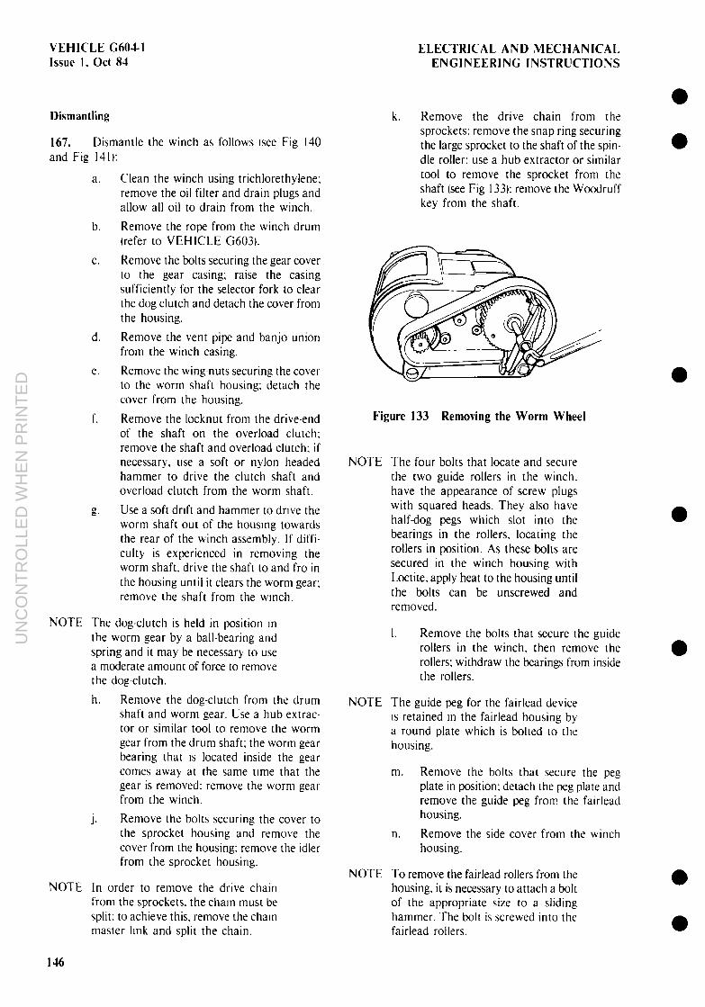
VEHICLE G6041 Issue 1. Ott 84
ELECTRICAL AND MECHANICAL ENGINEERING INSTRUCTIONS
Dismantling
167. Dismantle the winch as follows lsee Fig I40 and Fig 141):
a. Clean the winch using trichlorethylene; remove the oil filter and drain plugs and allow all oil to drain from the winch.
b. Remove the rope from the winch drum [refer to VEHICLE G6031.
C. Remove the bolts securing the gear cover to the gear casing; raise the casing sufficiently for the selector fork to clear the dog clutch and detach the cover from the housing.
d. Remove the vent pipe and banjo union from the winch casing.
e. Remove the wing-nuts securing the cover to the worm shaft housing; detach the cover from the housing.
f. Remove the locknut from the drive-end of the shaft on the overload clutch; remove the shaft and overload clutch: if necessary, use a soft or nylon headed hammer to drive the clutch shaft and overload clutch from the worm shaft.
g. Use a soft drift and hammer to drive the worm shaft out of the housmg towards the rear of the winch assembly. If diffi- culty is experienced in removing the worm shaft. drive the shaft to and fro in the housing until it clears the worm gear: remove the shaft from the wmch.
NOTE The dog-clutch is held in position m the worm gear by a ball-bearing and spring and it may be necessary to use a moderate amount of force to remove the dog-clutch.
h. Remove the dog-clutch from the drum shaft and worm gear. Use a hub extrac- tor or similar tool to remove the worm gear from the drum shaft; the worm gear bearing that IS located inside the gear comes away at the same tune that the gear is removed: remove the worm gear from the winch.
j. Remove the bolts securing the cover to the sprocket housing and remove the cover from the housing: remove the idler from the sprocket housing.
NOTE In order to remove the drive chain from the sprockets. the chain must be split: to achieve this. remove the chaln master link and split the chain.
k. Remove the drive chain from the sprockets: remove the snap ring securing the large sprocket to the shaft of the spin- dle roller: use a hub extractor or similar tool to remove the sprocket from the shaft (see Fig 133): remove the Woodruff key from the shaft.
Figure 133 Removing the Worm Wheel
NOTE
NOTE
NOTE
The four bolts that locate and secure the two guide rollers in the winch. have the appearance of screw plugs with squared heads. They also have half-dog pegs which slot into the bearings in the rollers, locating the rollers in position. As these bolts are secured in the winch housing with Loctite. apply heat to the housing until the bolts can be unscrewed and removed.
I. Remove the bolts that secure the guide rollers in the winch, then remove the rollers; withdraw the bearings from inside the rollers.
The guide peg for the fairlead device IS retained m the fairlead housing by a round plate which is bolted to the housing.
m. Remove the bolts that secure the peg plate in position; detach the peg plate and remove the guide peg from the fairlead housing.
n. Remove the side cover from the winch housing.
To remove the fairlead rollers from the housing. it is necessary to attach a bolt of the appropriate size to a sliding hammer. The bolt is screwed into the fairlead rollers.
e l
l
l
l
l
l 146
UN
CO
NT
RO
LLE
D W
HE
N P
RIN
TE
D

ELECTRICAL AND MECHANICAL ENGINEERING INSTRLICTIONS
VEHICLE C601-I l\sue 1. act 8-l
l
l
l
l
l
l
0. Use a sliding hammer to remove the fairlead rollers from the housing.
P. Remove the outer snap rmg from the farrlead guide shaft tsee Fig 134); remove the inner snap ring from the fairlead guide shaft tsee Frg 1351.
Figure 134 Fairlead guide Shaft - Outer Snap Ring
Figure 136 Fairlead Guide Shaft - O-Ring
S. Use a socket spanner and power-bar to maintain the pressure roller spring under tension whilst removing the lockbolt from the sprocket housing; slowly release the tension on the spring by turning the shaft until the spring is slack (see Fig 1371.
Figure 135 Fairlead Guide Shaft - Inner Snap Ring Figure 137 Releasing Roller Spring Tension
q. Use a sunable soft drift and hammer to drive the guide shaft out of the winch housing from the sprocket housing end; drive the shaft out of the housing until the O-ring on the end of the shaft can be removed; remove the O-ring from the shaft (see Fig I361 and remove the shaft from the fairlead housing and winch.
r. Remove the snap rings from the spindle; use a suitable soft drift and hammer to drive the spindle out of the winch housing: remove the fairlead housing from the winch.
t. Remove the grub-screw from the spring collars on either side of the spring (see Fig 1381; use a suitable soft drift and hammer to drive the shaft from the winch housing; remove the pressure roller assembly from the winch.
NOTE The control knob for the friction brake is a screw fit in the winch casing and is located above the sprocket housing.
U. Remove the control knob for the friction brake: use a pair of snipe-nosed pliers or a pointed instrument to remove the brake pad from the casing.
147
UN
CO
NT
RO
LLE
D W
HE
N P
RIN
TE
D

VEHICLE G60.4.1 Issue 1, Ott 8-l
ELECTRICAL AND MECHANICAL ENGINEERING INSTRUCTIONS
Figure 138 Guide Shaft Grub-screws
V. Remove the bolts securing the gear casing to the drum housing, remove the gear casing from the drum housing using a hub extractor or similar tool (see Fig 1391.
w. Remove the winch drum from the drum housing; clean and inspect all com- ponents, replace any components that are worn or damaged.
Figure 139 Removing the Gear Casing
Assembly
168. Assemble the winch as follows lsee Fig I-10 and Fig 141):
a. Install the winch drum in the drum housing; attach the gear casing to the drum housing and install and tighten the retaining bolts.
NOTE The control knob for the friction brake is a screw fit in the winch casing and is located above the sprocket casing.
Install the brake pad for the friction brake in the casing; install the control knob in the casing and screw it in a few turns.
Install the pressure roller assembly in the winch so that the shaft holes are aligned; install the pivot shaft about half-way into the housing.
Fit one spring collar over the shaft. then fit the spring and remaining spring collar over the shaft: push the pivot shaft fully home in the housing.
Insert the free ends of the spring into the spring collars. rotate the collars and spring until the detents in the shaft are aligned with the grub-screw holes in the collars: install and tighten the grub-screws (see Fig 138): ensure that the grub-screws lock securely into the detents in the shaft.
NOTE The spring for the pressure roller must be tensioned so that the pressure exerted by the spring on the cross shaft of the assembly maintains the pressure roller in firm contact with the winch drum.
f.
g.
h.
i.
Rotate the pivot shaft using a socket spanner and power bar until the pressure roller comes into firm contact with the winch drum. install and tighten the lockbolt.
Install the cross-threaded spindle in the winch; if necessary, use a soft drift and hammer to drive the spindle appros- imately three-quarters of the way into the winch: fit the fairlead housing over the spindle then drive the spindle fully home in the winch: fit the snap rings to the spindle shaft.
Install the guide shaft for the fairlead. from the sprocket housing end. so that the end of the shaft protrudes far enough through the fairlead to allow the 0-rmg to be fitted: fit the O-ring to the guide shaft and push the shaft fully home in the winch: fit the inner and outer snap rings to the shaft [see Fig I34 and Fig 1351.
Install the fairlead rollers in the housing; if necessary. use a nylon headed hammer to drive the rollers fully home III the housing.
l
l
l
l
l
l
l
148
UN
CO
NT
RO
LLE
D W
HE
N P
RIN
TE
D

ELECTRICAL AND MECHANICAL VEHICLE G604-1 ENGINEERING INSTRUCTIONS Issue 1, Ott 83
l
l
l
l
j. Install the guide peg m the fairlead housing; ensure that the tongue on the end of the peg slots into the grooves in the cross-threaded spindle; fit the plate to the housing, and install and tighten the plate retaining bolts.
k. Fit the bearings for the gutde rollers into the ends of the rollers; coat the threads of the roller retaining bolts with Loctite 270; fit the rollers into the winch housing. and install and tighten the retaining bolts: ensure that the half-dog pegs on the bolts slot into the inner races of the bearings in the ends of the rollers.
I. Fit the Woodruff key to the spindle shaft and fit the sprocket to the spindle shaft: if necessary, heat the sprocket in oil to expand the centre boss prior to fitting: fit the snap ring to the shaft to retain the sprocket in place.
m. Loop the split drive chain over the sprocket and drive gear: install the master link and fit the spring clip.
n. Install the chain tensioning idler in the sprocket housing; rotate the idler until the tension on the chain is correct and tighten the securing bolt.
0. Install the roller bearing in the worm gear and fit the gear and bearing to the drum shaft; if necessary, use a soft drift and hammer to drive the gear and bearing fully home on the shaft.
NOTE The dog-clutch is held m position in the worm gear by a ball hearing and spring.
P.
q.
r.
S.
t.
U.
4’
W.
Install the spring and ball bearing in the worm gear and press the dog-clutch into the worm gear; do not dislodge the ball bearing and spring during this procedure.
Fit the worm shaft into the winch; if necessary. rotate the drum and worm gear to engage the spiral on the worm shaft.
Fit the overload clutch assembly to the winch so that the shaft for the overload clutch is encompassed by the hollow worm shaft; fit and tighten the locknut to the drive end of the clutch shaft.
Fit the cover to the casing. and install and tighten the wing-nuts.
Fit the vent pipe and banjo union to the winch casing.
Fit the gear cover to the casing so that the selector fork engages in the radial groove around the dog-clutch; install and tighten the cover retaining bolts.
Fit the rope to the winch drum (refer to VEHICLE G6031.
Install and tighten the oil drain plug; fill the winch gearbox with two litres of clean OEP 220 oil; install and tighten the oil filler plug.
l
l
l 1491150
UN
CO
NT
RO
LLE
D W
HE
N P
RIN
TE
D

ELECTRICAL AND MECHANICAL VEHICLE (2604-l ENGINEERING INSTRUCTIONS Issue I, Ott 84
l
l
l
l
l
1. Retainrng bolt 2 Spnng washer 3. Srde cover 4. 0-nng 5. Tnplex drive charn 6. Bolt 7. Idler 8. Woodruff key 9. Spindle roller
10. Ball beanng 11. Snap ring 12. Farrlead devrce 13. Ball bearing 14. Fairlead rollers 15. Washer 16. Spring washer 17 Bolt 18. Grease nipple 19. Guide peg 20. Peg plate 21. Spring washer 22. Bolt 23. Snap ring 24. Farrlead guide shaft 25. O-ring 26 Compressron spnng 27. Ball bearing 28. Winch drum 29. Wire rope 30. Ball bearing
31. Drum housing 32. Shaft 33. Spring collars 34. Roller tension spring 35. Grub screw 36. Bolt 37. Grease nipple 38. Roller arm 39. Ball bearing 40. Pressure roller 41. Roller arm 42. Washer 43. Shaft 44. O-ring 45. Half-dog bolt 46. Ball bearing 47. Guide rollers 48. Winch retainrng pm 49 Safety pm 50. Locking ring 51. Sprocket 52. Control knob 53. Coil spring 54. Brake pad 55. Bolt 56. Washer 57. Nut 58 Bolt 59 Washer
11
24
. .
27
\O
\
iI
---._ pg 28
32 33 34
/-.7 42 43 4? -?
l
l Figure 140 Winch - Drum Assembly
UN
CO
NT
RO
LLE
D W
HE
N P
RIN
TE
D

h
m
-.
UN
CO
NT
RO
LLE
D W
HE
N P
RIN
TE
D

ELECTRJCAL AND MECHANICAL VEHICLE G604-1 ENGINEERING JNSTRUCTIONS Bssoe 1, 8ct 84
1
PROJECTION DO NOT SCALE
THREAD Mllr.1.5
MATERIAL : H 5
N” OFF 3
DIMENSIONS ARE IN MILLIMETRES
I ORAWING PRACTICE SCALE PROJECT NO MAINTENANCE ENBINEERINB pIB%HCV --. _ _._-__ FULL SIZE OEPARTYEYT IF OEFIA”STIWI5
--_ . ..- .- .-._. -. --. -._-- -----.-. -.-_---
C PRO, pit , I.I,““r-OLL ,
DESIGN APPROVED Pl.SlHlC. MA1 -----m-m---_-
O~lEP8lu 83_ _ IWCDN ‘.-. t-
I 5 I K
-4 MERCEDES BENZ SPECIAL GUIDE BOLTS
DRG No MEA 882 mta A2 EYE, NO
I 7 I 0
UNLESS OTHERWISE STATEQ
DIMENSIONS ARE IN YlLLII4ETRES
LINEAR TOLERANCES 2 8:88 ANGULAR TOLERANCES t
GEOYEV+Y TOLERANCING r0 AS1100 PART 10 LIMITS APPLf AFTER PLATING AN0 BEFORE PAINTING MATERIAL SPEC CONrROLS ISlOCK TOLERANCE.
3 I L
Class 26.0 Code 8 (MEA 115182A3
Figure 142 Special Guide Bolt
UN
CO
NT
RO
LLE
D W
HE
N P
RIN
TE
D