Embed Size (px)
Citation preview
True life inside
LIN
EA C
LIM
AG
ENER
AL
CAT
ALO
GU
E 2012

By contacting Gruppo Ferraro means you
can count on a single important reference
point.
A reliable supplier, moreover an experien-
ced, qualified and proactive partner.
For more than 30 years carefully treating air and water to guarantee a more comfortable life. Everyday .
The three companies making the Gruppo Fer-
raro areIndustrie Ferraro, LMF Clima and Rame
Cz work in perfect synergy and for more than
thirty years have worked in the fields of liquid
and gas coduction, manufacturing components
for their use in numerous fields such as heating,
air conditioning, refrigeration and automation.
Through constant investment in machinery,
equipment and technology applied to the tre-
atment of air and the recovery of clean energy,
has allowed Gruppo Ferraroto consolidate its
leading role in this field.

Ferraro Group.Three companies, one trustworthy partner.
This natural and spontaneous tendency to
continuously evolve in infrastructures and pro-
duction processes has been the key to suc-
cess which started at the Group’s birth, keeps
evolving in the present and is the starting point
for the its’ future.
The company LMF Clima of the Fer-
raro Group,designs and manufactures
equipment and units for air-conditio-
ning, heating and air-treatment sy-
stems. Founded in 1980, LMF Clima
distinguishes itself for its ability to
develop skills and processes, with the
aim of ensuring the highest quality of
its products.
In 1996 LMF designed its first complete
line of air treatment, thereby becoming
an essential reference point to those in
the sector.
After 30 years of experience, LMF
carries out its designs on a surfa-
ce of 10.000MQ with state of the art
machinery and equipment and offers
solutions which meet the needs of an
extremely demanding market, where
the ratio of Quality/price is the discri-
minating factor.
The will to introduce itself as a valued
and proactive partner, one willing to
attentively evaluate various new so-
lutions that technology has to offer is
LMF’s main aim.
Quality. Our value since 1980.

Indexwww.lmf.it
8
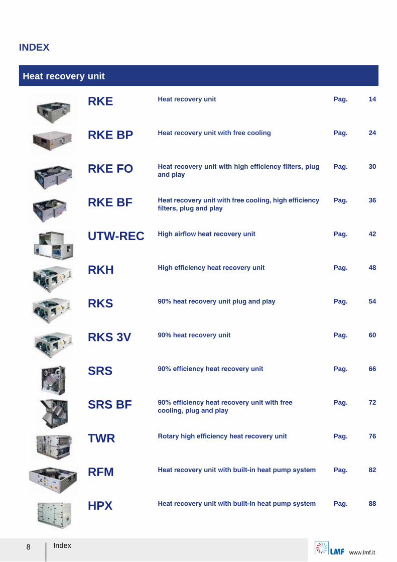
INDEX
Heat recovery unit
RKE Heat recovery unit Pag. 14
RKE BP Heat recovery unit with free cooling Pag. 24
RKE FO Heat recovery unit with high efルciency ルlters, plug and play
Pag. 30
RKE BF Heat recovery unit with free cooling, high efルciency ルlters, plug and play
Pag. 36
UTW-REC High airレow heat recovery unit Pag. 42
RKH High efルciency heat recovery unit Pag. 48
RKS 90% heat recovery unit plug and play Pag. 54
RKS 3V 90% heat recovery unit Pag. 60
SRS 90% efルciency heat recovery unit Pag. 66
SRS BF 90% efルciency heat recovery unit with free cooling, plug and play
Pag. 72
TWR Rotary high efルciency heat recovery unit Pag. 76
RFM Heat recovery unit with built-in heat pump system Pag. 82
HPX Heat recovery unit with built-in heat pump system Pag. 88
www.lmf.itIndex 9
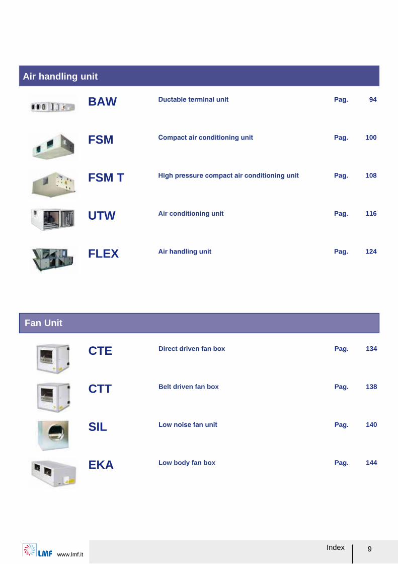
Fan Unit
Air handling unit
CTE Direct driven fan box Pag. 134
CTT Belt driven fan box Pag. 138
SIL Low noise fan unit Pag. 140
EKA Low body fan box Pag. 144
BAW Ductable terminal unit Pag. 94
FSM Compact air conditioning unit Pag. 100
FSM T High pressure compact air conditioning unit Pag. 108
UTW Air conditioning unit Pag. 116
FLEX Air handling unit Pag. 124
Indexwww.lmf.it
10
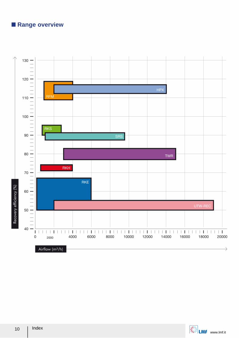
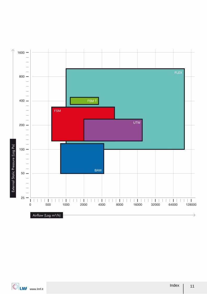
Q Range overview
Airflow (m³/h)
Reco
very
effic
iency
(%
)
www.lmf.itIndex 11
Airflow (Log m³/h)
Ext
ern
al Sta
tic
Pre
ssure
(Lo
g P
a)
Indexwww.lmf.it
12
Model
RKE √ √ √ √ √
RKE BP √ √ √ √ √
RKE FO √ √ √ √ √ √ √
RKE BF √ √ √ √ √ √ √
UTW-REC √ √ √
RKH √ √ √ √ √
RKS √ √ √ √ √ √ √
RKS 3V √ √ √ √ √
SRS √ √ √ √
SRS BF √ √ √ √ √
TWR √ √ √
BAW √ √ √
FSM √ √
FSM T √ √
UTW √ √ √ √
FLEX √ √ √ √ √ √ √ √
CTE √ √
CTT √ √
SIL √
EKA √
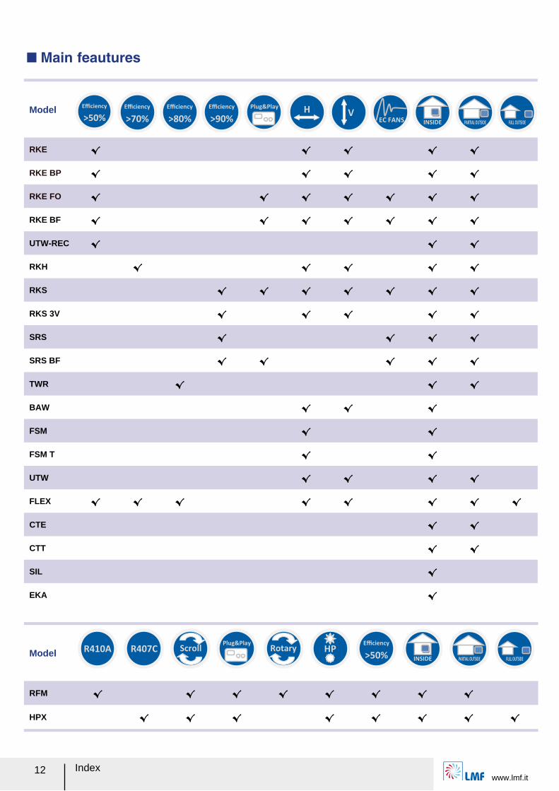
>50%
Efficiency
>70%
Efficiency
>90%
Efficiency
H
V
EC FANS
INSIDE PARTIAL OUTSIDE
FULL OUTSIDE
Q Main feautures
Model
RFM √ √ √ √ √ √ √ √
HPX √ √ √ √ √ √ √ √
>80%
Efficiency
Plug&Play
R410A R407C
Scroll
Rotary
HP
INSIDE PARTIAL OUTSIDE
FULL OUTSIDE
>50%
Efficiency
Plug&Play
www.lmf.itIndex 13
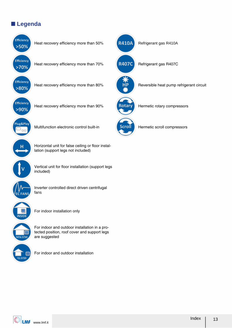
Q Legenda
Heat recovery efルciency more than 50% Refrigerant gas R410A
Heat recovery efルciency more than 70% Refrigerant gas R407C
Heat recovery efルciency more than 80% Reversible heat pump refrigerant circuit
Heat recovery efルciency more than 90% Hermetic rotary compressors
Multifunction electronic control built-in Hermetic scroll compressors
Horizontal unit for false ceiling or レoor instal-lation (support legs not included)
Vertical unit for レoor installation (support legs included)
Inverter controlled direct driven centrifugal fans
For indoor installation only
For indoor and outdoor installation in a pro-tected position, roof cover and support legs are suggested
For indoor and outdoor installation
>50%
Efficiency
>70%
Efficiency
>90%
Efficiency
H
R410A
R407C
Scroll
Rotary
HP
V
EC FANS
INSIDE
PARTIAL OUTSIDE
FULL OUTSIDE
>80%
Efficiency
Plug&Play
RKE
Heat recovery unitwww.lmf.it
14
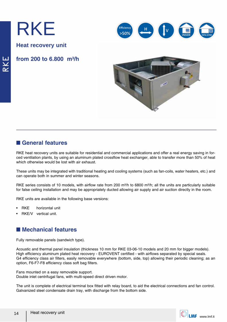
RKE heat recovery units are suitable for residential and commercial applications and offer a real energy saving in for-ced ventilation plants, by using an aluminum plated crossレow heat exchanger, able to transfer more than 50% of heat which otherwise would be lost with air exhaust.
These units may be integrated with traditional heating and cooling systems (such as fan-coils, water heaters, etc.) and can operate both in summer and winter seasons.
RKE series consists of 10 models, with airレow rate from 200 m³/h to 6800 m³/h; all the units are particularly suitable for false ceiling installation and may be appropriately ducted allowing air supply and air suction directly in the room.
RKE units are available in the following base versions:
ー RKE horizontal unitー RKE/V vertical unit.
Q General features
Fully removable panels (sandwich type).
Acoustic and thermal panel insulation (thickness 10 mm for RKE 03-06-10 models and 20 mm for bigger models).High efルciency aluminum plated heat recovery - EUROVENT certiルed - with airレows separated by special seals.G4 efルciency class air ルlters, easily removable everywhere (bottom, side, top) allowing their periodic cleaning; as an option, F6-F7-F8 efルciency class soft bag ルlters.
Fans mounted on a easy removable support.Double inlet centrifugal fans, with multi-speed direct driven motor.
The unit is complete of electrical terminal box ルtted with relay board, to aid the electrical connections and fan control.Galvanized steel condensate drain tray, with discharge from the bottom side.
Q Mechanical features
RKEHeat recovery unit
from 200 to 6.800 m³/h
>50%
Efficiency
H
V
INSIDE PARTIAL OUTSIDE
RKE
www.lmf.itHeat recovery unit 15
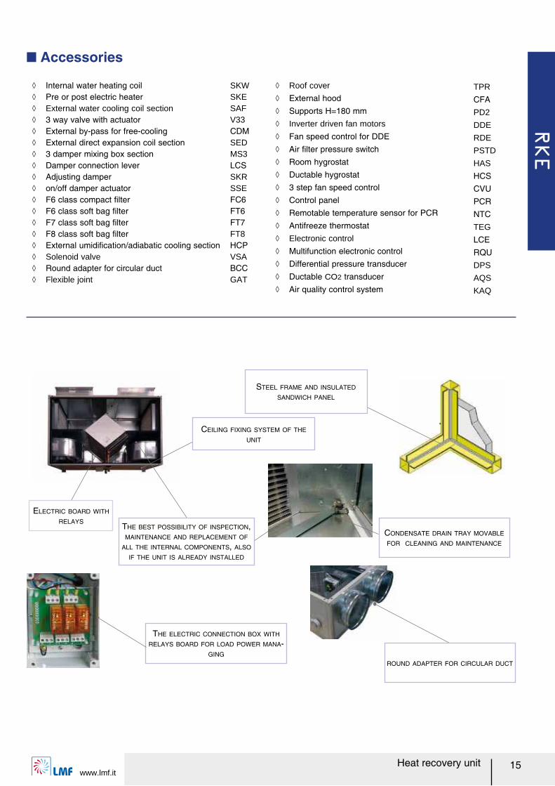
ノ Internal water heating coil SKW ノ Pre or post electric heater SKE ノ External water cooling coil section SAF ノ 3 way valve with actuator V33 ノ External by-pass for free-cooling CDM ノ External direct expansion coil section SED ノ 3 damper mixing box section MS3 ノ Damper connection lever LCS ノ Adjusting damper SKR ノ on/off damper actuator SSE ノ F6 class compact ルlter FC6 ノ F6 class soft bag ルlter FT6 ノ F7 class soft bag ルlter FT7 ノ F8 class soft bag ルlter FT8 ノ External umidiルcation/adiabatic cooling section HCP ノ Solenoid valve VSA ノ Round adapter for circular duct BCC ノ Flexible joint GAT
Q Accessories
CONDENSATE DRAIN TRAY MOVABLE
FOR CLEANING AND MAINTENANCE
THE BEST POSSIBILITY OF INSPECTION,
MAINTENANCE AND REPLACEMENT OF
ALL THE INTERNAL COMPONENTS, ALSO
IF THE UNIT IS ALREADY INSTALLED
STEEL FRAME AND INSULATED
SANDWICH PANEL
ELECTRIC BOARD WITH
RELAYS
THE ELECTRIC CONNECTION BOX WITH
RELAYS BOARD FOR LOAD POWER MANA-
GING
ROUND ADAPTER FOR CIRCULAR DUCT
CEILING FIXING SYSTEM OF THE
UNIT
ノ Roof cover TPR ノ External hood CFA ノ Supports H=180 mm PD2 ノ Inverter driven fan motors DDE ノ Fan speed control for DDE RDE ノ Air ルlter pressure switch PSTD ノ Room hygrostat HAS ノ Ductable hygrostat HCS ノ 3 step fan speed control CVU ノ Control panel PCR ノ Remotable temperature sensor for PCR NTC ノ Antifreeze thermostat TEG ノ Electronic control LCE ノ Multifunction electronic control RQU ノ Differential pressure transducer DPS ノ Ductable CO2 transducer AQS ノ Air quality control system KAQ
RKE
Heat recovery unitwww.lmf.it
16
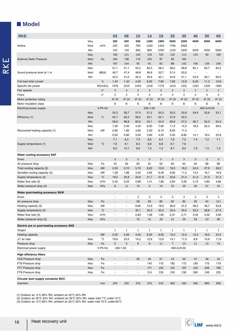
(1) Outdoor air -5°C 80% RH, ambient air 20°C 50% RH(2) Outdoor air 32°C 50% RH, ambient air 26°C 50% RH, water inlet 7°C outlet 12°C(3) Outdoor air -5°C 80% RH, ambient air 20°C 50% RH, water inlet 70°C outlet 60°C
Q Model
RKE 03 06 10 14 19 25 30 40 50 60
Airレow
Max
m³/h
300 500 930 1400 1900 2500 3200 4000 5000 6000
Med 200 300 750 1200 1400 1700 2500 - - -
Min 100 150 600 850 1000 1100 1800 3000 4000 5000
External Static Pressure
Max
Pa
163 121 100 129 125 120 114 120 99 188
Med 184 136 115 100 97 56 164 - - -
Min 167 144 90 91 82 68 142 105 139 208
Sound pressure level at 1 m
Max
dB(A)
51,1 51,1 52,2 62,3 58,4 56,0 58,8 62,1 63,7 64,5
Med 49,7 47,4 48,8 56,9 53,7 51,0 53,5 - - -
Min 44,3 41,0 45,3 45,6 42,1 44,6 51,1 54,9 59,1 62,0
Full load total current A 1,40 1,40 4,00 6,00 7,80 7,60 12,6 6,20 11,2 10,8
Speciルc fan power W/(m3/s) 1376 1019 1003 1418 1172 1019 1301 1183 1428 1594
Fan speeds n° 3 3 3 3 3 3 3 2 2 2
Poles n° 2 2 4 4 4 4 4 4 4 4
Motor protection rating IP 20 IP 20 IP 20 IP 20 IP 20 IP 20 IP 20 IP 20 IP 20 IP 20
Motor insulation class B B B B B B B B B B
Electrical power supply V-Ph-Hz 230-1-50 400-3+N-50
Efルciency (1)
Max
%
53,3 58,7 57,0 51,2 50,3 55,5 53,9 54,9 53,8 53,1
Med 55,7 62,2 58,5 52,1 52,1 57,9 55,5 - - -
Min 59,6 66,8 60,0 54,1 54,0 60,6 57,5 56,7 55,3 54,3
Recovered heating capacity (1)
Max
kW
1,30 2,40 4,40 6,00 7,90 11,5 14,3 18,2 22,4 26,5
Med 0,90 1,60 3,60 5,20 6,10 8,20 11,5 - - -
Min 0,50 0,80 3,00 3,80 4,50 5,50 8,60 14,1 18,4 22,6
Supply temperature (1)
Max
°C
7,1 8,3 7,9 6,6 6,4 7,6 7,2 7,4 7,2 7,1
Med 7,6 9,1 8,3 6,8 6,8 8,1 7,6 - - -
Min 8,5 10,1 8,6 7,3 7,3 8,7 8,0 7,9 7,5 7,3
Water cooling accessory SAFRows 3 3 3 3 3 3 3 3 3 3
Air pressure drop Max Pa 43 59 63 81 83 64 84 84 66 69
Total cooling capacity (2) Max kW 2,30 3,10 5,70 8,20 10,8 16,5 19,2 24,0 27,9 28,2
Sensible cooling capacity (2) Max kW 1,38 1,86 3,42 4,92 6,48 9,90 11,5 14,4 16,7 16,9
Supply temperature (2) Max °C 19,5 20,9 20,9 21,7 21,9 20,6 21,5 21,3 21,3 21,3
Water レow rate (2) Max m³/h 0,40 0,53 0,98 1,41 1,86 2,84 3,30 4,13 4,80 4,85
Water pressure drop (2) Max kPa 6 11 15 9 10 22 29 30 27 24
Water post-heating accessory SKWRows - - 3 3 3 3 3 3 3 3
Air pressure drop Max Pa - - 58 63 85 62 85 90 94 111
Heating capacity (3) Max kW - - 9,60 14,9 18,6 26,9 31,5 39,5 46,7 53,8
Supply temperature (3) Max °C - - 35,1 34,3 32,0 35,6 33,0 33,2 28,8 27,9
Water レow rate (3) Max m³/h - - 0,83 1,28 1,60 2,31 2,71 3,40 4,02 4,63
Water pressure drop (3) Max kPa - - 15 41 28 21 29 53 23 26
Electric pre or post-heating accessory SKEStages 1 1 1 1 1 1 1 1 1 1
Heating capacity kW 2,00 4,00 4,50 6,00 9,00 12,0 12,0 12,0 18,0 24,0
スT air side Max °C 19,6 23,5 14,2 12,6 13,9 14,1 11,0 8,8 10,6 11,8
Pressure drop Max Pa 5 5 8 8 11 7 10 11 13 15
Electrical power supply V-Ph-Hz 230-1-50 400-3+N-50
High efルciency ルltersFC6 Pressure drop Max Pa - - 26 45 51 43 50 47 38 34
FT6 Pressure drop Max Pa - - - 145 170 162 172 189 175 179
FT7 Pressure drop Max Pa - - - 171 199 191 197 229 205 185
FT8 Pressure drop Max Pa - - - 214 239 230 238 260 248 225
Circular duct supply connector BCCDiameter mm 200 200 315 315 315 355 400 450 600 600
RKE
www.lmf.itHeat recovery unit 17
Ext
erna
l Sta
tic P
ress
ure
(Pa)
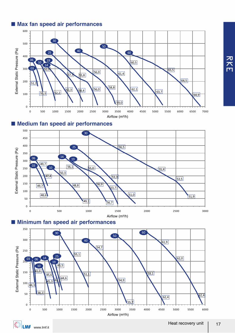
Q Max fan speed air performances
0
100
200
300
400
500
600
0 500 1000 1500 2000 2500 3000 3500 4000 4500 5000 5500 6000 6500 7000
19
50
60
06
14
30
10
03
2540
51,1 52,262,3 58,4 56,0
58,862,1
63,7
64,5
65,5
64,9
60,5
61,4
59,0
56,055,857,3
52,0
51,1
0
50
100
150
200
250
300
350
400
450
500
0 500 1000 1500 2000 2500 3000
03
06
10
1419
25
30
49,7
48,6
47,4
49,7
48,8
49,1
50,3
56,9
56,7
56,1
53,7
55,0
51,0
51,353,5
56,5
55,4
51,9
0
50
100
150
200
250
300
350
0 500 1000 1500 2000 2500 3000 3500 4000 4500 5000 5500 6000
0603
10
14
19
30
40
5060
25
44,3
41,0
38,2
45,3
45,644,6
51,1
54,9
59,1
62,0
45,5
55,1
54,7
55,7
62,4
61,9
62,4
42,1
Airレow (m³/h)
Ext
erna
l Sta
tic P
ress
ure
(Pa)
Airレow (m³/h)
Ext
erna
l Sta
tic P
ress
ure
(Pa)
Airレow (m³/h)
Q Medium fan speed air performances
Q Minimum fan speed air performances
RKE
Heat recovery unitwww.lmf.it
18
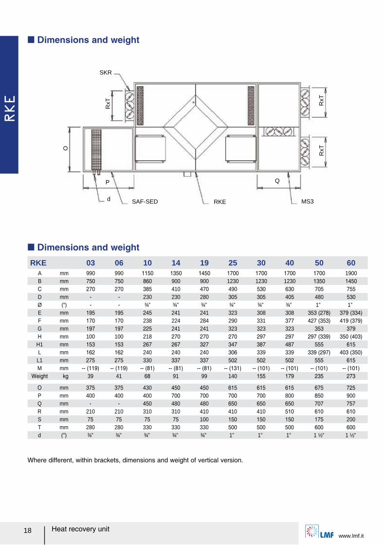
Where different, within brackets, dimensions and weight of vertical version.
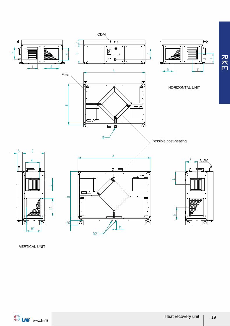
Q Dimensions and weight
RKE 03 06 10 14 19 25 30 40 50 60A mm 990 990 1150 1350 1450 1700 1700 1700 1700 1900B mm 750 750 860 900 900 1230 1230 1230 1350 1450C mm 270 270 385 410 470 490 530 630 705 755D mm - - 230 230 280 305 305 405 480 530Ø (ォ) - - ¾” ¾” ¾” ¾” ¾” ¾” 1” 1”E mm 195 195 245 241 241 323 308 308 353 (278) 379 (334)F mm 170 170 238 224 284 290 331 377 427 (353) 419 (379)G mm 197 197 225 241 241 323 323 323 353 379H mm 100 100 218 270 270 270 297 297 297 (339) 350 (403)
H1 mm 153 153 267 267 327 347 387 487 555 615L mm 162 162 240 240 240 306 339 339 339 (297) 403 (350)
L1 mm 275 275 330 337 337 502 502 502 555 615M mm -- (119) -- (119) -- (81) -- (81) -- (81) -- (131) -- (101) -- (101) -- (101) -- (101)
Weight kg 39 41 68 91 99 140 155 179 235 273
O mm 375 375 430 450 450 615 615 615 675 725P mm 400 400 400 700 700 700 700 800 850 900Q mm - - 450 480 480 650 650 650 707 757R mm 210 210 310 310 410 410 410 510 610 610S mm 75 75 75 75 100 150 150 150 175 200T mm 280 280 330 330 330 500 500 500 600 600d ('') ¾” ¾” ¾” ¾” ¾” 1” 1” 1” 1 ½” 1 ½”
Q Dimensions and weight
SKR
d
P
SAF-SED RKE MS3
Q
RxT
O
RxT
RxT
RKE
www.lmf.itHeat recovery unit 19
Possible post-heating
Filter
CDM
CDM
VERTICAL UNIT
HORIZONTAL UNIT
RKE
Heat recovery unitwww.lmf.it
20
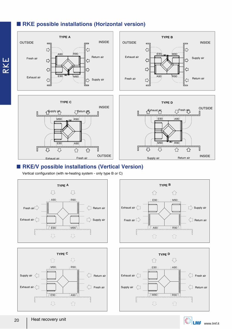
Q RKE possible installations (Horizontal version)
Q RKE/V possible installations (Vertical Version) Vertical conルguration (with re-heating system - only type B or C)
A90 R90
E90 M90
M90 R90
E90 A90
E90 M90
A90 R90
E90 A90
M90 R90
TYPE A
OUTSIDE INSIDE
Fresh air
Exhaust airSupply air
Return air
TYPE C
OUTSIDE
Supply air Return air
Exhaust air Fresh air
TYPE B
OUTSIDE INSIDE
Exhaust air
Fresh air Return air
Supply air
INSIDETYPE D
INSIDE
Exhaust air Fresh air
Supply air Return air
OUTSIDE
A90 R90
E90 M90
M90 R90
E90 A90
E90 A90
M90 R90
E90 M90
A90 R90
TYPE A
Fresh air
Exhaust air Supply air
Return air
TYPE C
Supply air
Exhaust air Fresh air
Return air
TYPE D
Exhaust air
Supply air Return air
Fresh air
TYPE B
Exhaust air
Fresh air Return air
Supply air
RKE
www.lmf.itHeat recovery unit 21
This digital controller is intended for temperature regulation in environments equipped with heat recovery unit or air conditioning unit. The device automatically controls the fan speed (manual or automatic 2/3 step fan speed control) as well as the possible valves/electric heater in order to adjust the room temperature in the most suitable way. Temperature acquisition can be performed either with the control panel internal sensor or with an external one (accessory NTC).
The control panel is suitable to manage two water coil for heating/cooling (4 pipes system), or single coil (2 pipes system) and/or electric heater; moreover it includes a manual or automatic heating/cooling changeover, an economy function to reduce power consumption (it allows to temporary set an energy saving mode through a reduction of the actual set point temperature by a step when in heating mode, or increasing it by the same step when in cooling mode), and clogged ルlter alarm by setting the time-to-maintenance.
This device can drive in a proportional way both valves and fan in order to control room temperature with the highest comfort and energy saving, following a proportional band for fan and proportional and integral for valves: the regulator will drive this valve through power pulses with one second resolution in a way that its stem will reach the position needed for the regulation, thus performing a modulation. The regulator, as soon as power is ルrst applied, and before it starts the actual regulation, will perform a stem position re-synchronization cycle, which is obtained by closing the valve for a time which is 150% of the value stored as nominal opening time. This cycle will be periodically repeated in order to recover possible positioning errors which might be accumulated during time.
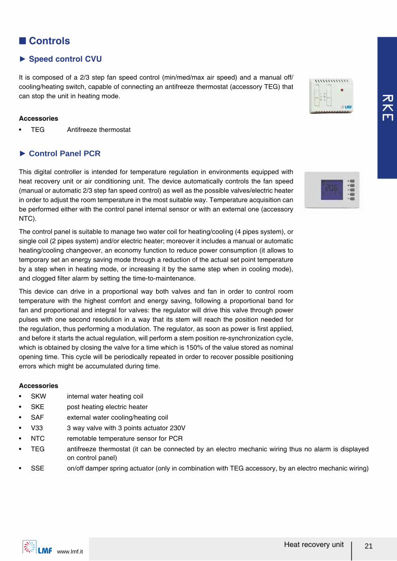
Q Controls
Ź Speed control CVU
It is composed of a 2/3 step fan speed control (min/med/max air speed) and a manual off/cooling/heating switch, capable of connecting an antifreeze thermostat (accessory TEG) that can stop the unit in heating mode.
Accessories
ー TEG Antifreeze thermostat
Ź Control Panel PCR
Accessoriesー SKW internal water heating coil
ー SKE post heating electric heater
ー SAF external water cooling/heating coil
ー V33 3 way valve with 3 points actuator 230V
ー NTC remotable temperature sensor for PCR
ー TEG antifreeze thermostat (it can be connected by an electro mechanic wiring thus no alarm is displayed on control panel)
ー SSE on/off damper spring actuator (only in combination with TEG accessory, by an electro mechanic wiring)
RKE
Heat recovery unitwww.lmf.it
22
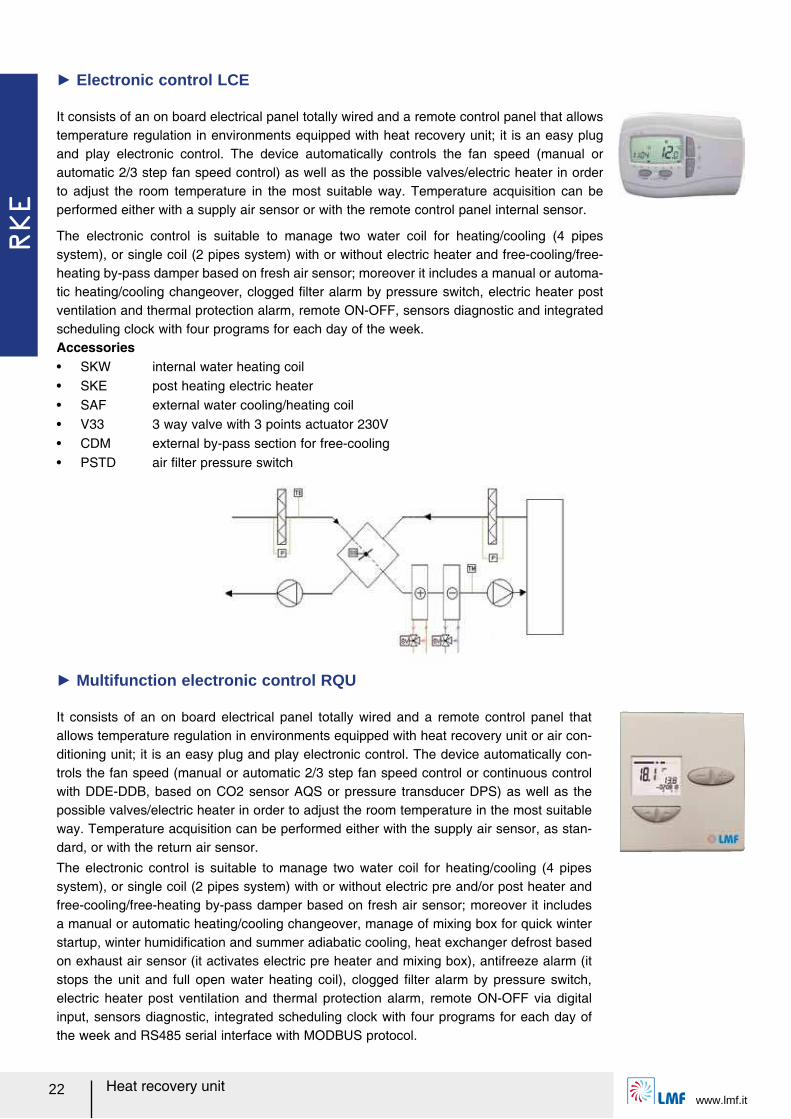
It consists of an on board electrical panel totally wired and a remote control panel that allows temperature regulation in environments equipped with heat recovery unit or air con-ditioning unit; it is an easy plug and play electronic control. The device automatically con-trols the fan speed (manual or automatic 2/3 step fan speed control or continuous control with DDE-DDB, based on CO2 sensor AQS or pressure transducer DPS) as well as the possible valves/electric heater in order to adjust the room temperature in the most suitable way. Temperature acquisition can be performed either with the supply air sensor, as stan-dard, or with the return air sensor.
The electronic control is suitable to manage two water coil for heating/cooling (4 pipes system), or single coil (2 pipes system) with or without electric pre and/or post heater and free-cooling/free-heating by-pass damper based on fresh air sensor; moreover it includes a manual or automatic heating/cooling changeover, manage of mixing box for quick winter startup, winter humidiルcation and summer adiabatic cooling, heat exchanger defrost based on exhaust air sensor (it activates electric pre heater and mixing box), antifreeze alarm (it stops the unit and full open water heating coil), clogged ルlter alarm by pressure switch, electric heater post ventilation and thermal protection alarm, remote ON-OFF via digital input, sensors diagnostic, integrated scheduling clock with four programs for each day of the week and RS485 serial interface with MODBUS protocol.
Ź Multifunction electronic control RQU
It consists of an on board electrical panel totally wired and a remote control panel that allows temperature regulation in environments equipped with heat recovery unit; it is an easy plug and play electronic control. The device automatically controls the fan speed (manual or automatic 2/3 step fan speed control) as well as the possible valves/electric heater in order to adjust the room temperature in the most suitable way. Temperature acquisition can be performed either with a supply air sensor or with the remote control panel internal sensor.
The electronic control is suitable to manage two water coil for heating/cooling (4 pipes system), or single coil (2 pipes system) with or without electric heater and free-cooling/free-heating by-pass damper based on fresh air sensor; moreover it includes a manual or automa-tic heating/cooling changeover, clogged ルlter alarm by pressure switch, electric heater post ventilation and thermal protection alarm, remote ON-OFF, sensors diagnostic and integrated scheduling clock with four programs for each day of the week.
Ź Electronic control LCE
Accessoriesー SKW internal water heating coilー SKE post heating electric heaterー SAF external water cooling/heating coilー V33 3 way valve with 3 points actuator 230Vー CDM external by-pass section for free-coolingー PSTD air ルlter pressure switch
RKE
www.lmf.itHeat recovery unit 23
TM
SV SV
SS
P
TR
SS
SS
SS
P
KAQ
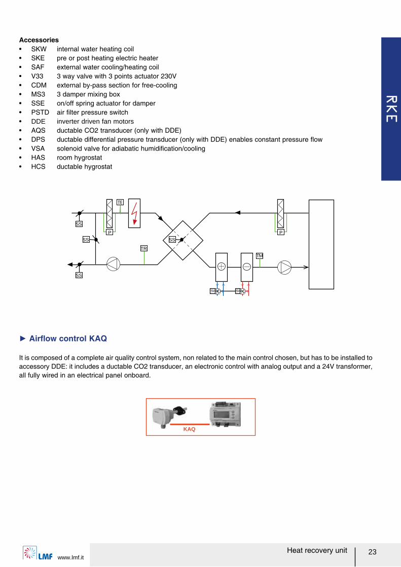
It is composed of a complete air quality control system, non related to the main control chosen, but has to be installed to accessory DDE: it includes a ductable CO2 transducer, an electronic control with analog output and a 24V transformer, all fully wired in an electrical panel onboard.
Ź Airレow control KAQ
Accessoriesー SKW internal water heating coilー SKE pre or post heating electric heaterー SAF external water cooling/heating coilー V33 3 way valve with 3 points actuator 230Vー CDM external by-pass section for free-coolingー MS3 3 damper mixing boxー SSE on/off spring actuator for damperー PSTD air ルlter pressure switchー DDE inverter driven fan motorsー AQS ductable CO2 transducer (only with DDE)ー DPS ductable differential pressure transducer (only with DDE) enables constant pressure レowー VSA solenoid valve for adiabatic humidiルcation/coolingー HAS room hygrostatー HCS ductable hygrostat
RKE BP
Heat recovery unitwww.lmf.it
24
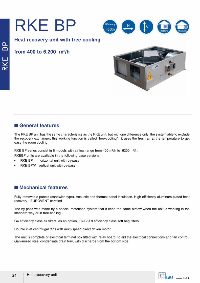
RKE BPHeat recovery unit with free cooling
from 400 to 6.200 m³/h
The RKE BP unit has the same characteristics as the RKE unit, but with one difference only: the system able to exclude the recovery exchanger; this working function is called ォfree-coolingャ, it uses the fresh air at the temperature to get easy the room cooling.
RKE BP series consist in 6 models with airレow range from 400 m³/h to 6200 m³/h.RKEBP units are available in the following base versions:ー RKE BP horizontal unit with by-passー RKE BP/V vertical unit with by-pass
Q General features
Fully removable panels (sandwich type). Acoustic and thermal panel insulation. High efルciency aluminum plated heat recovery - EUROVENT certiルed -
The by-pass was made by a special motorised system that it keep the same airレow when the unit is working in the standard way or in free-cooling.
G4 efルciency class air ルlters; as an option, F6-F7-F8 efルciency class soft bag ルlters.
Double inlet centrifugal fans with multi-speed direct driven motor.
The unit is complete of electrical terminal box ルtted with relay board, to aid the electrical connections and fan control.Galvanized steel condensate drain tray, with discharge from the bottom side.
Q Mechanical features
>50%
Efficiency
H
V
INSIDE PARTIAL OUTSIDE
RKE BP
www.lmf.itHeat recovery unit 25
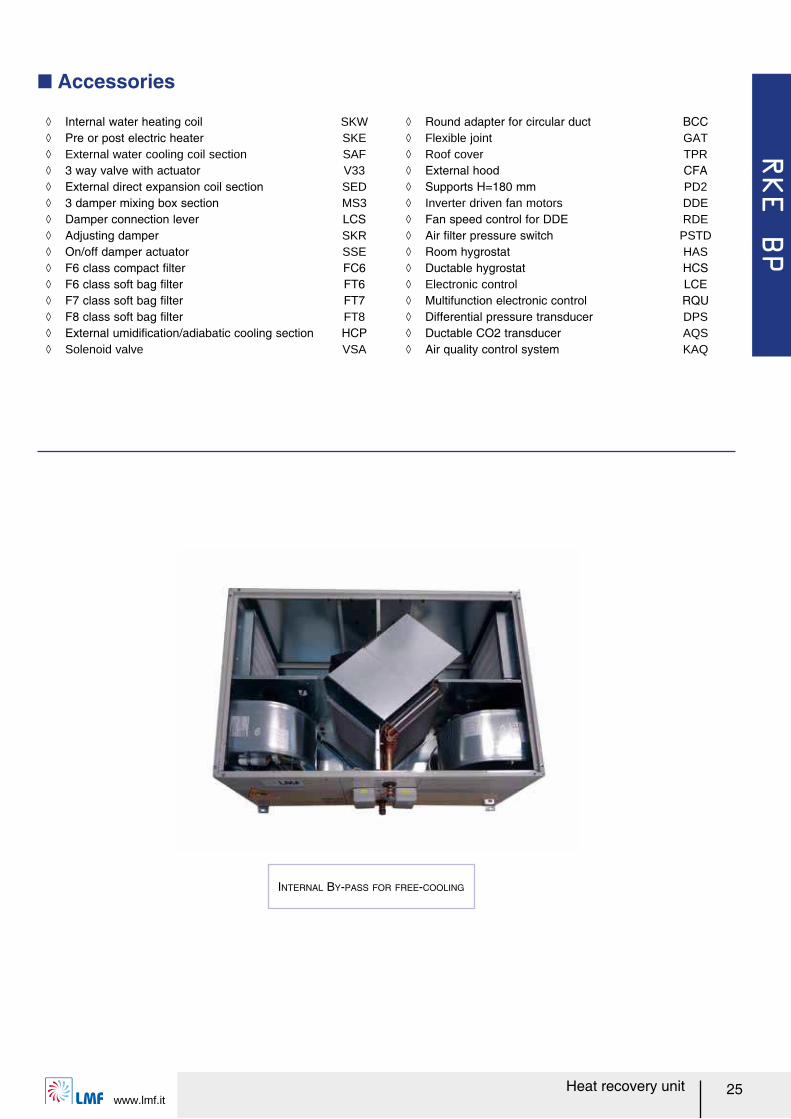
Q Accessories
ノ Internal water heating coil SKW ノ Pre or post electric heater SKE ノ External water cooling coil section SAF ノ 3 way valve with actuator V33 ノ External direct expansion coil section SED ノ 3 damper mixing box section MS3 ノ Damper connection lever LCS ノ Adjusting damper SKR ノ On/off damper actuator SSE ノ F6 class compact ルlter FC6 ノ F6 class soft bag ルlter FT6 ノ F7 class soft bag ルlter FT7 ノ F8 class soft bag ルlter FT8 ノ External umidiルcation/adiabatic cooling section HCP ノ Solenoid valve VSA
INTERNAL BY-PASS FOR FREE-COOLING
ノ Round adapter for circular duct BCC ノ Flexible joint GAT ノ Roof cover TPR ノ External hood CFA ノ Supports H=180 mm PD2 ノ Inverter driven fan motors DDE ノ Fan speed control for DDE RDE ノ Air ルlter pressure switch PSTD ノ Room hygrostat HAS ノ Ductable hygrostat HCS ノ Electronic control LCE ノ Multifunction electronic control RQU ノ Differential pressure transducer DPS ノ Ductable CO2 transducer AQS ノ Air quality control system KAQ
RKE BP
Heat recovery unitwww.lmf.it
26
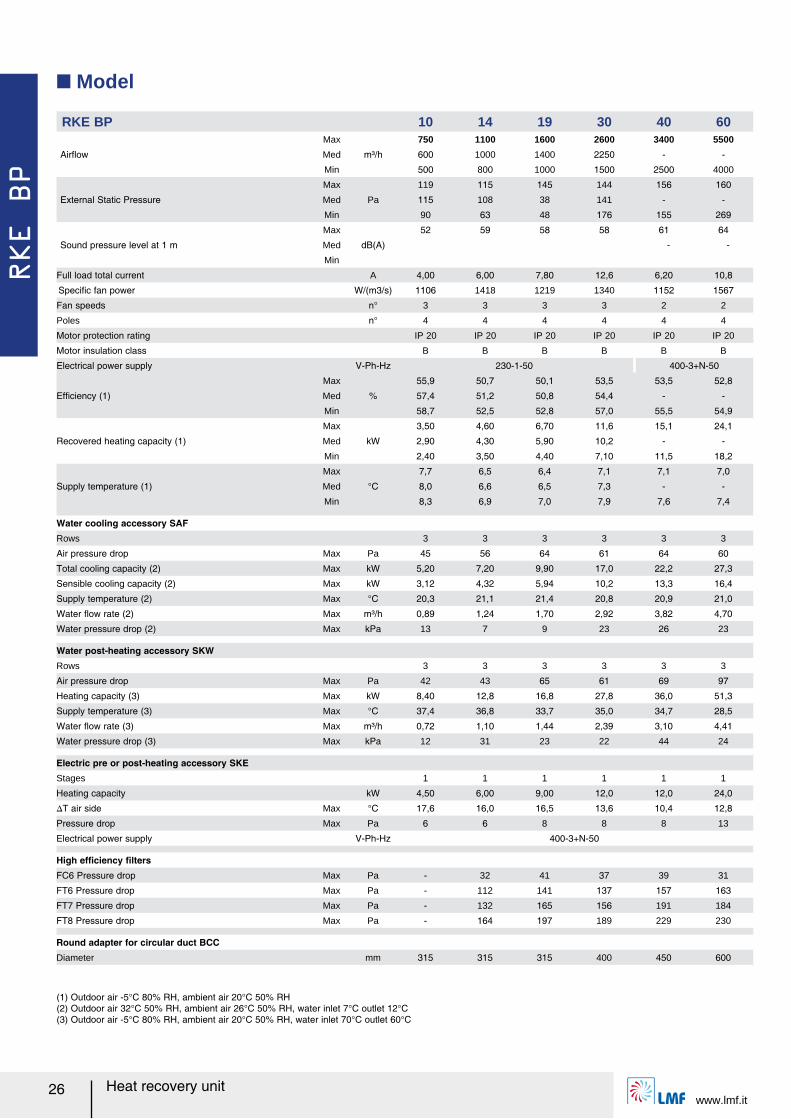
Q Model
(1) Outdoor air -5°C 80% RH, ambient air 20°C 50% RH(2) Outdoor air 32°C 50% RH, ambient air 26°C 50% RH, water inlet 7°C outlet 12°C(3) Outdoor air -5°C 80% RH, ambient air 20°C 50% RH, water inlet 70°C outlet 60°C
RKE BP 10 14 19 30 40 60
Airレow
Max
m³/h
750 1100 1600 2600 3400 5500
Med 600 1000 1400 2250 - -
Min 500 800 1000 1500 2500 4000
External Static Pressure
Max
Pa
119 115 145 144 156 160
Med 115 108 38 141 - -
Min 90 63 48 176 155 269
Sound pressure level at 1 m
Max
dB(A)
52 59 58 58 61 64
Med - -
Min
Full load total current A 4,00 6,00 7,80 12,6 6,20 10,8
Speciルc fan power W/(m3/s) 1106 1418 1219 1340 1152 1567
Fan speeds n° 3 3 3 3 2 2
Poles n° 4 4 4 4 4 4
Motor protection rating IP 20 IP 20 IP 20 IP 20 IP 20 IP 20
Motor insulation class B B B B B B
Electrical power supply V-Ph-Hz 230-1-50 400-3+N-50
Efルciency (1)
Max
%
55,9 50,7 50,1 53,5 53,5 52,8
Med 57,4 51,2 50,8 54,4 - -
Min 58,7 52,5 52,8 57,0 55,5 54,9
Recovered heating capacity (1)
Max
kW
3,50 4,60 6,70 11,6 15,1 24,1
Med 2,90 4,30 5,90 10,2 - -
Min 2,40 3,50 4,40 7,10 11,5 18,2
Supply temperature (1)
Max
°C
7,7 6,5 6,4 7,1 7,1 7,0
Med 8,0 6,6 6,5 7,3 - -
Min 8,3 6,9 7,0 7,9 7,6 7,4
Water cooling accessory SAFRows 3 3 3 3 3 3
Air pressure drop Max Pa 45 56 64 61 64 60
Total cooling capacity (2) Max kW 5,20 7,20 9,90 17,0 22,2 27,3
Sensible cooling capacity (2) Max kW 3,12 4,32 5,94 10,2 13,3 16,4
Supply temperature (2) Max °C 20,3 21,1 21,4 20,8 20,9 21,0
Water レow rate (2) Max m³/h 0,89 1,24 1,70 2,92 3,82 4,70
Water pressure drop (2) Max kPa 13 7 9 23 26 23
Water post-heating accessory SKWRows 3 3 3 3 3 3
Air pressure drop Max Pa 42 43 65 61 69 97
Heating capacity (3) Max kW 8,40 12,8 16,8 27,8 36,0 51,3
Supply temperature (3) Max °C 37,4 36,8 33,7 35,0 34,7 28,5
Water レow rate (3) Max m³/h 0,72 1,10 1,44 2,39 3,10 4,41
Water pressure drop (3) Max kPa 12 31 23 22 44 24
Electric pre or post-heating accessory SKEStages 1 1 1 1 1 1
Heating capacity kW 4,50 6,00 9,00 12,0 12,0 24,0
スT air side Max °C 17,6 16,0 16,5 13,6 10,4 12,8
Pressure drop Max Pa 6 6 8 8 8 13
Electrical power supply V-Ph-Hz 400-3+N-50
High efルciency ルltersFC6 Pressure drop Max Pa - 32 41 37 39 31
FT6 Pressure drop Max Pa - 112 141 137 157 163
FT7 Pressure drop Max Pa - 132 165 156 191 184
FT8 Pressure drop Max Pa - 164 197 189 229 230
Round adapter for circular duct BCCDiameter mm 315 315 315 400 450 600
RKE BP
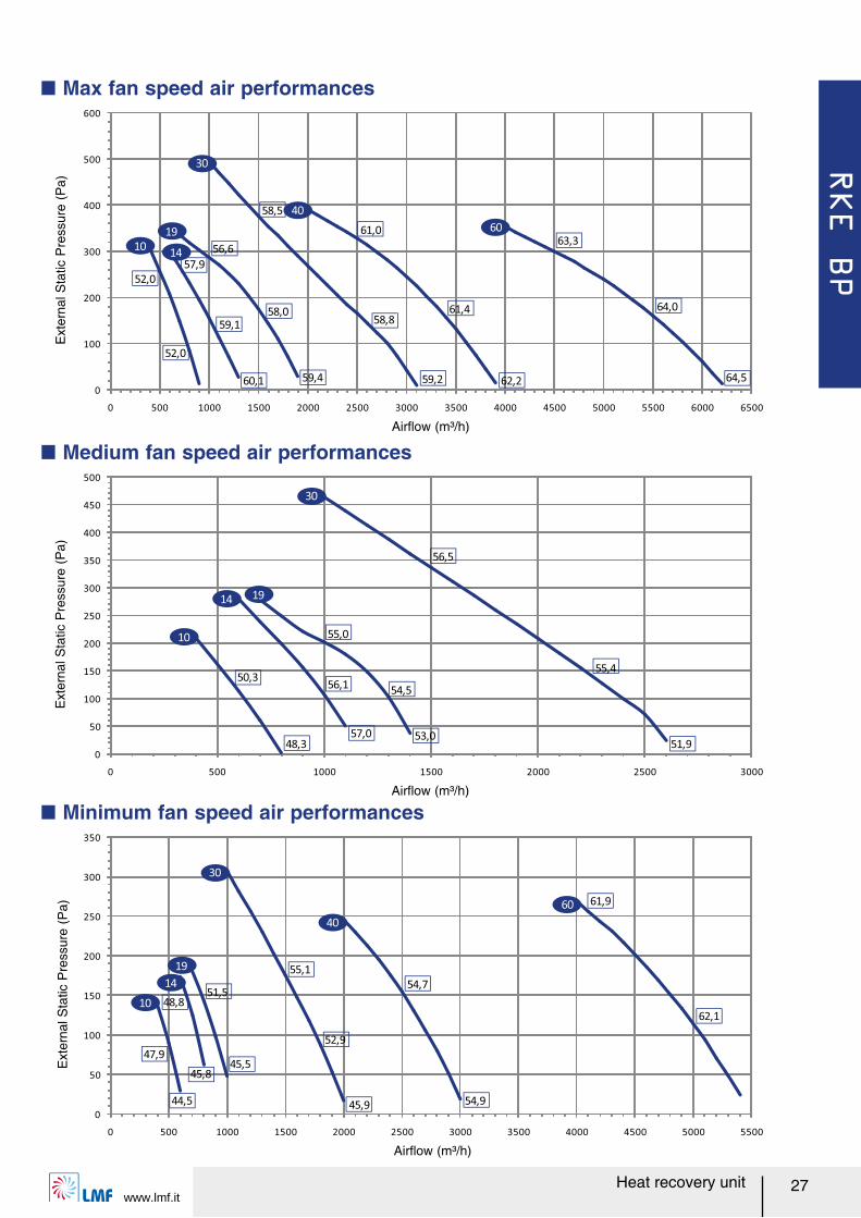
www.lmf.itHeat recovery unit 27
Ext
erna
l Sta
tic P
ress
ure
(Pa)
Q Max fan speed air performances
0
100
200
300
400
500
600
0 500 1000 1500 2000 2500 3000 3500 4000 4500 5000 5500 6000 6500
19 60
14
30
10
40
59,1
52,0
58,058,8
61,4 64,0
52,0
57,9
60,1 59,4
56,6
59,2
58,5
62,2
61,063,3
64,5
0
50
100
150
200
250
300
350
0 500 1000 1500 2000 2500 3000 3500 4000 4500 5000 5500
19
60
14
30
10
40
47,9
44,5
45,8
48,8
45,5
51,5
55,1
52,9
45,9
54,7
54,9
61,9
62,1
Airレow (m³/h)
Ext
erna
l Sta
tic P
ress
ure
(Pa)
Airレow (m³/h)
Q Medium fan speed air performances
0
50
100
150
200
250
300
350
400
450
500
0 500 1000 1500 2000 2500 3000
1914
30
10
50,3
48,3
56,1
57,0
54,5
53,0
55,0
55,4
56,5
51,9
Airレow (m³/h)
Ext
erna
l Sta
tic P
ress
ure
(Pa)
Q Minimum fan speed air performances
RKE BP
Heat recovery unitwww.lmf.it
28
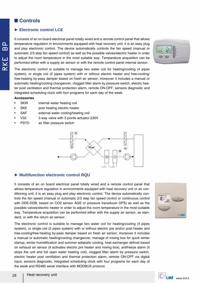
It consists of an on board electrical panel totally wired and a remote control panel that allows temperature regulation in environments equipped with heat recovery unit or air con-ditioning unit; it is an easy plug and play electronic control. The device automatically con-trols the fan speed (manual or automatic 2/3 step fan speed control or continuous control with DDE-DDB, based on CO2 sensor AQS or pressure transducer DPS) as well as the possible valves/electric heater in order to adjust the room temperature in the most suitable way. Temperature acquisition can be performed either with the supply air sensor, as stan-dard, or with the return air sensor.
The electronic control is suitable to manage two water coil for heating/cooling (4 pipes system), or single coil (2 pipes system) with or without electric pre and/or post heater and free-cooling/free-heating by-pass damper based on fresh air sensor; moreover it includes a manual or automatic heating/cooling changeover, manage of mixing box for quick winter startup, winter humidiルcation and summer adiabatic cooling, heat exchanger defrost based on exhaust air sensor (it activates electric pre heater and mixing box), antifreeze alarm (it stops the unit and full open water heating coil), clogged ルlter alarm by pressure switch, electric heater post ventilation and thermal protection alarm, remote ON-OFF via digital input, sensors diagnostic, integrated scheduling clock with four programs for each day of the week and RS485 serial interface with MODBUS protocol.
Ź Multifunction electronic control RQU
It consists of an on board electrical panel totally wired and a remote control panel that allows temperature regulation in environments equipped with heat recovery unit; it is an easy plug and play electronic control. The device automatically controls the fan speed (manual or automatic 2/3 step fan speed control) as well as the possible valves/electric heater in order to adjust the room temperature in the most suitable way. Temperature acquisition can be performed either with a supply air sensor or with the remote control panel internal sensor.
The electronic control is suitable to manage two water coil for heating/cooling (4 pipes system), or single coil (2 pipes system) with or without electric heater and free-cooling/free-heating by-pass damper based on fresh air sensor; moreover it includes a manual or automatic heating/cooling changeover, clogged ルlter alarm by pressure switch, electric hea-ter post ventilation and thermal protection alarm, remote ON-OFF, sensors diagnostic and integrated scheduling clock with four programs for each day of the week.
Ź Electronic control LCE
Q Controls
Accessoriesー SKW internal water heating coilー SKE post heating electric heaterー SAF external water cooling/heating coilー V33 3 way valve with 3 points actuator 230Vー PSTD air ルlter pressure switch
RKE BP
www.lmf.itHeat recovery unit 29
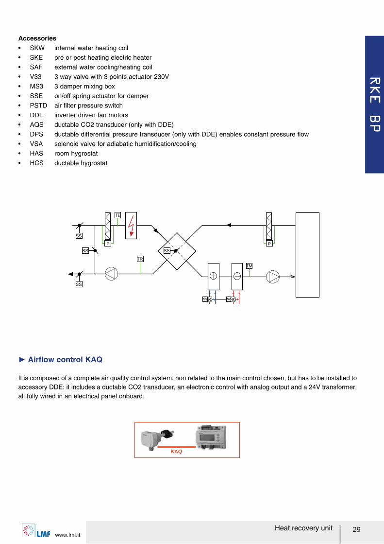
Accessoriesー SKW internal water heating coilー SKE pre or post heating electric heaterー SAF external water cooling/heating coilー V33 3 way valve with 3 points actuator 230Vー MS3 3 damper mixing boxー SSE on/off spring actuator for damperー PSTD air ルlter pressure switchー DDE inverter driven fan motors
ー AQS ductable CO2 transducer (only with DDE)ー DPS ductable differential pressure transducer (only with DDE) enables constant pressure レowー VSA solenoid valve for adiabatic humidiルcation/coolingー HAS room hygrostatー HCS ductable hygrostat
TM
SV SV
SS
P
TR
SS
SS
SS
P
KAQ
It is composed of a complete air quality control system, non related to the main control chosen, but has to be installed to accessory DDE: it includes a ductable CO2 transducer, an electronic control with analog output and a 24V transformer, all fully wired in an electrical panel onboard.
Ź Airレow control KAQ
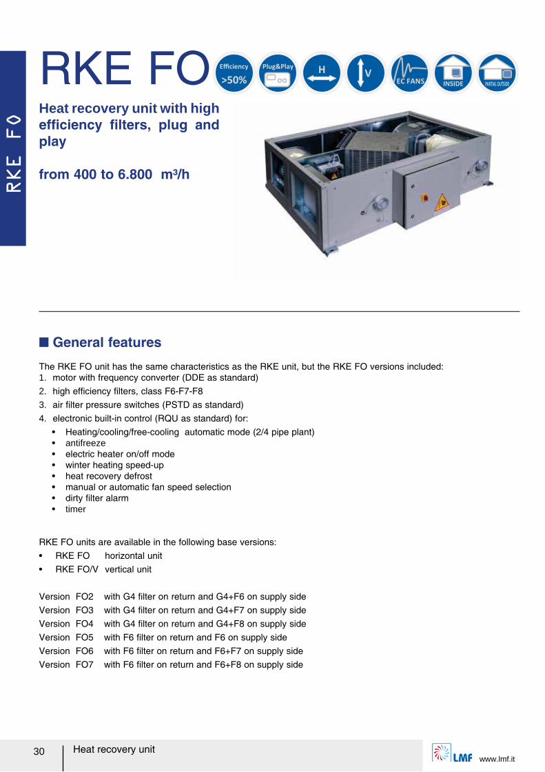
RKE FO
Heat recovery unitwww.lmf.it
30
Heat recovery unit with high efルciency ルlters, plug and play
from 400 to 6.800 m³/h
The RKE FO unit has the same characteristics as the RKE unit, but the RKE FO versions included:1. motor with frequency converter (DDE as standard)2. high efルciency ルlters, class F6-F7-F8 3. air ルlter pressure switches (PSTD as standard)4. electronic built-in control (RQU as standard) for:
ー Heating/cooling/free-cooling automatic mode (2/4 pipe plant)ー antifreezeー electric heater on/off modeー winter heating speed-upー heat recovery defrostー manual or automatic fan speed selectionー dirty ルlter alarmー timer
RKE FO units are available in the following base versions:ー RKE FO horizontal unit ー RKE FO/V vertical unit
Version FO2 with G4 ルlter on return and G4+F6 on supply sideVersion FO3 with G4 ルlter on return and G4+F7 on supply sideVersion FO4 with G4 ルlter on return and G4+F8 on supply sideVersion FO5 with F6 ルlter on return and F6 on supply side Version FO6 with F6 ルlter on return and F6+F7 on supply sideVersion FO7 with F6 ルlter on return and F6+F8 on supply side
Q General features
RKE FO Plug&Play
H
V
INSIDE PARTIAL OUTSIDE
>50%
Efficiency
EC FANS
RKE FO
www.lmf.itHeat recovery unit 31
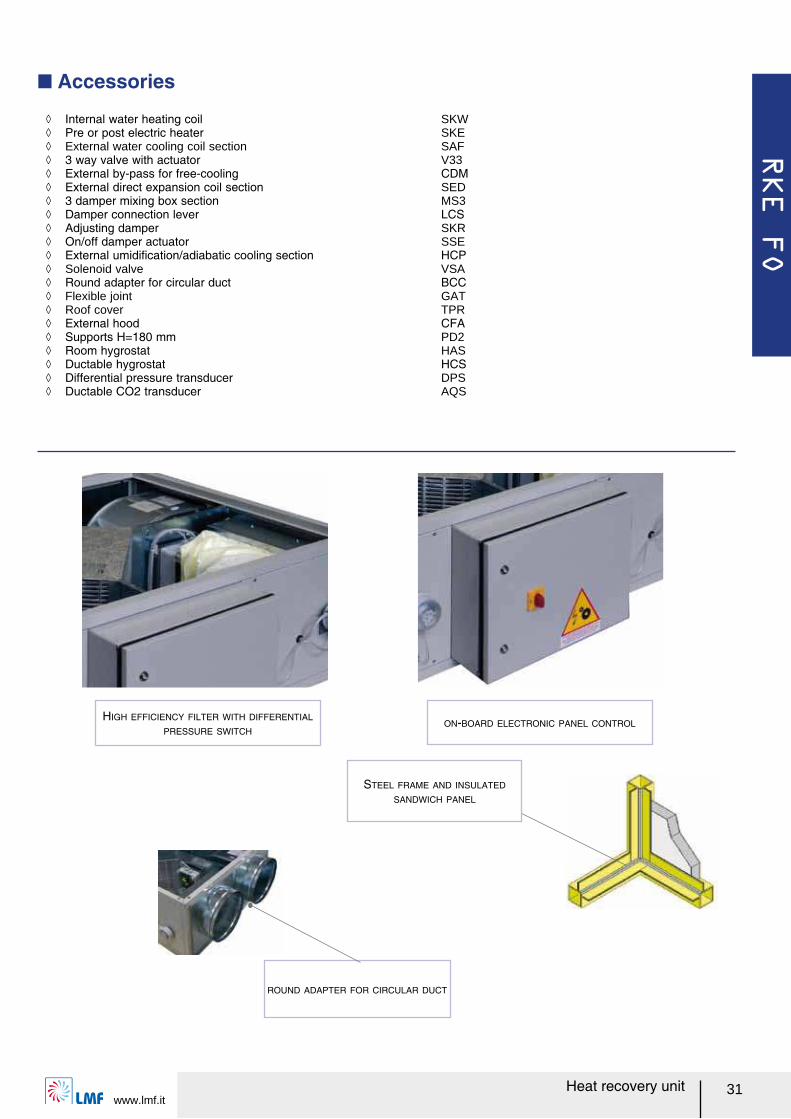
Q Accessories
HIGH EFFICIENCY FILTER WITH DIFFERENTIAL
PRESSURE SWITCHON-BOARD ELECTRONIC PANEL CONTROL
ノ Internal water heating coil SKW ノ Pre or post electric heater SKE ノ External water cooling coil section SAF ノ 3 way valve with actuator V33 ノ External by-pass for free-cooling CDM ノ External direct expansion coil section SED ノ 3 damper mixing box section MS3 ノ Damper connection lever LCS ノ Adjusting damper SKR ノ On/off damper actuator SSE ノ External umidiルcation/adiabatic cooling section HCP ノ Solenoid valve VSA ノ Round adapter for circular duct BCC ノ Flexible joint GAT ノ Roof cover TPR ノ External hood CFA ノ Supports H=180 mm PD2 ノ Room hygrostat HAS ノ Ductable hygrostat HCS ノ Differential pressure transducer DPS ノ Ductable CO2 transducer AQS
STEEL FRAME AND INSULATED
SANDWICH PANEL
ROUND ADAPTER FOR CIRCULAR DUCT
RKE FO
Heat recovery unitwww.lmf.it
32
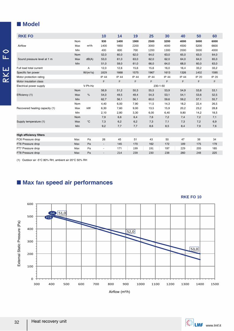
Q Model
(1) Outdoor air -5°C 80% RH, ambient air 20°C 50% RH
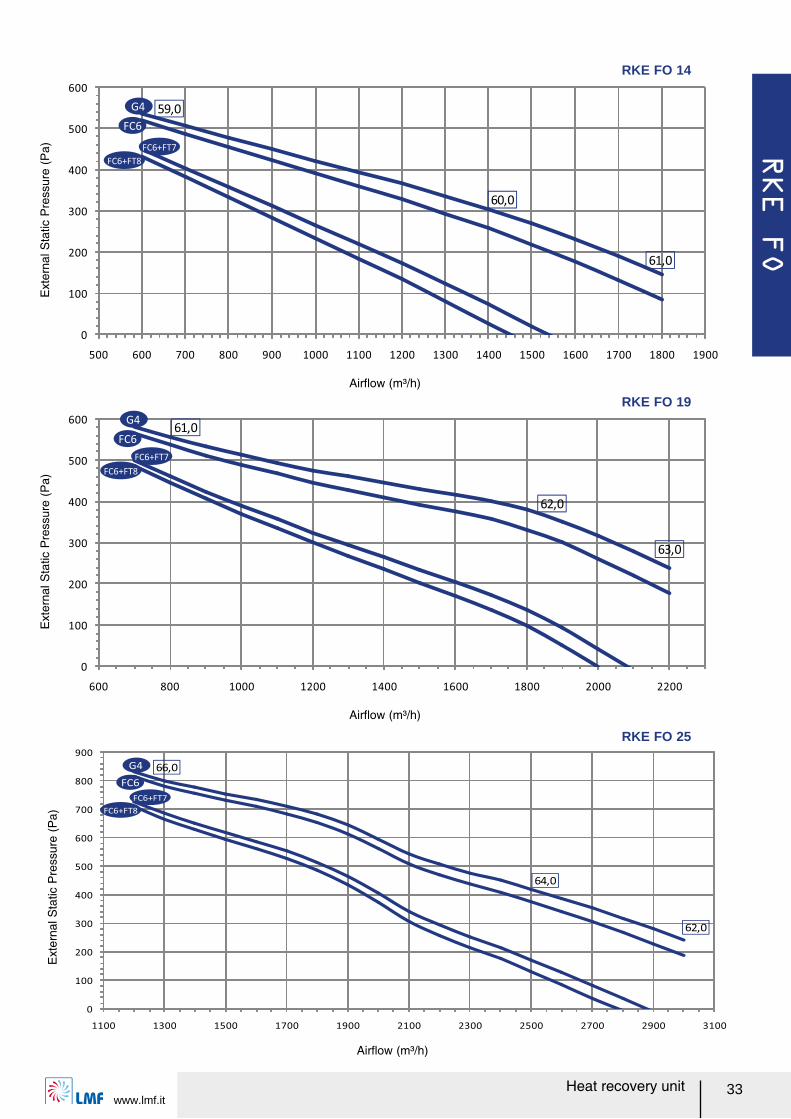
Q Max fan speed air performances
RKE FO 10 14 19 25 30 40 50 60
Airレow
Nom
m³/h
930 1400 1900 2500 3200 4000 5000 6000
Max 1400 1850 2200 3000 4000 4500 5200 6600
Min 400 600 700 1200 1300 2000 3000 4000
Sound pressure level at 1 m
Nom
dB(A)
52,0 60,0 62,0 64,0 63,0 65,0 63,0 64,0
Max 53,0 61,0 63,0 62,0 62,0 64,0 64,0 65,0
Min 51,0 59,0 61,0 66,0 64,0 68,0 60,0 63,0
Full load total current A 12,0 12,6 15,6 15,6 16,0 16,4 33,2 33,2
Speciルc fan power W/(m³/s) 1829 1668 1575 1967 1613 1326 1402 1595
Motor protection rating IP 44 IP 44 IP 44 IP 44 IP 44 IP 44 IP 20 IP 20
Motor insulation class F F F F F F F F
Electrical power supply V-Ph-Hz 230-1-50
Efルciency (1)
Nom
%
56,9 51,2 50,3 55,5 53,9 54,9 53,8 53,1
Max 54,0 49,5 49,4 54,3 53,1 54,1 53,6 52,5
Min 62,7 56,1 56,1 60,0 59,6 59,2 57,1 55,7
Recovered heating capacity (1)
Nom
kW
4,40 6,00 7,90 11,5 14,3 18,2 22,4 26,5
Max 6,30 7,60 9,00 13,5 15,9 20,2 23,2 28,8
Min 2,10 2,80 3,30 6,00 6,40 9,80 14,2 18,5
Supply temperature (1)
Nom
°C
7,9 6,6 6,4 7,6 7,2 7,4 7,2 7,1
Max 7,3 6,2 6,2 7,3 7,1 7,3 7,2 6,9
Min 9,2 7,7 7,7 8,6 8,5 8,4 7,9 7,6
High efルciency ルltersFC6 Pressure drop Max Pa 26 45 51 43 50 47 38 34
FT6 Pressure drop Max Pa - 145 170 162 172 189 175 179
FT7 Pressure drop Max Pa - 171 199 191 197 229 205 185
FT8 Pressure drop Max Pa - 214 239 230 238 260 248 225
0
100
200
300
400
500
600
300 400 500 600 700 800 900 1000 1100 1200 1300 1400 1500
52,0
53,0
51,0
FC6
G4
Airレow (m³/h)
Ext
erna
l Sta
tic P
ress
ure
(Pa)
RKE FO 10
RKE FO
www.lmf.itHeat recovery unit 33
0
100
200
300
400
500
600
500 600 700 800 900 1000 1100 1200 1300 1400 1500 1600 1700 1800 1900
59,0
60,0
61,0
FC6+FT8
G4
FC6
FC6+FT7
Airレow (m³/h)
Ext
erna
l Sta
tic P
ress
ure
(Pa)
RKE FO 14
0
100
200
300
400
500
600
700
800
900
1100 1300 1500 1700 1900 2100 2300 2500 2700 2900 3100
64,0
62,0
66,0
FC6+FT7
FC6+FT8
G4
FC6
Airレow (m³/h)
Ext
erna
l Sta
tic P
ress
ure
(Pa)
0
100
200
300
400
500
600
600 800 1000 1200 1400 1600 1800 2000 2200
62,0
63,0
61,0G4
FC6
FC6+FT7
FC6+FT8
Airレow (m³/h)
Ext
erna
l Sta
tic P
ress
ure
(Pa)
RKE FO 19
RKE FO 25
RKE FO
Heat recovery unitwww.lmf.it
34
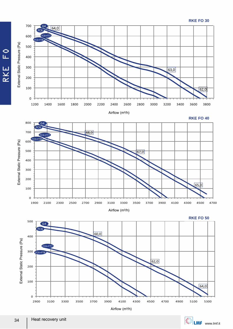
0
100
200
300
400
500
600
700
1200 1400 1600 1800 2000 2200 2400 2600 2800 3000 3200 3400 3600 3800
62,0
63,0
64,0G4
FC6
FC6+FT7
FC6+FT8
Airレow (m³/h)
Ext
erna
l Sta
tic P
ress
ure
(Pa)
RKE FO 30
0
100
200
300
400
500
600
700
800
1900 2100 2300 2500 2700 2900 3100 3300 3500 3700 3900 4100 4300 4500 4700
68,0
65,0
67,0
G4
FC6
FC6+FT7
FC6+FT8
Airレow (m³/h)
Ext
erna
l Sta
tic P
ress
ure
(Pa)
0
100
200
300
400
500
2900 3100 3300 3500 3700 3900 4100 4300 4500 4700 4900 5100 5300
64,0
62,0
60,0
FC6+FT7
FC6+FT8
G4
FC6
Airレow (m³/h)
Ext
erna
l Sta
tic P
ress
ure
(Pa)
RKE FO 50
RKE FO 40
RKE FO
www.lmf.itHeat recovery unit 35
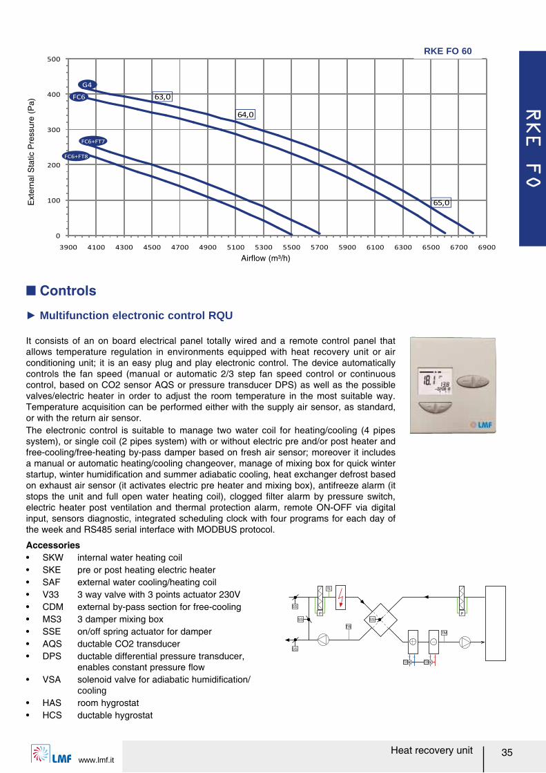
It consists of an on board electrical panel totally wired and a remote control panel that allows temperature regulation in environments equipped with heat recovery unit or air conditioning unit; it is an easy plug and play electronic control. The device automatically controls the fan speed (manual or automatic 2/3 step fan speed control or continuous control, based on CO2 sensor AQS or pressure transducer DPS) as well as the possible valves/electric heater in order to adjust the room temperature in the most suitable way. Temperature acquisition can be performed either with the supply air sensor, as standard, or with the return air sensor.The electronic control is suitable to manage two water coil for heating/cooling (4 pipes system), or single coil (2 pipes system) with or without electric pre and/or post heater and free-cooling/free-heating by-pass damper based on fresh air sensor; moreover it includes a manual or automatic heating/cooling changeover, manage of mixing box for quick winter startup, winter humidiルcation and summer adiabatic cooling, heat exchanger defrost based on exhaust air sensor (it activates electric pre heater and mixing box), antifreeze alarm (it stops the unit and full open water heating coil), clogged ルlter alarm by pressure switch, electric heater post ventilation and thermal protection alarm, remote ON-OFF via digital input, sensors diagnostic, integrated scheduling clock with four programs for each day of the week and RS485 serial interface with MODBUS protocol.
Ź Multifunction electronic control RQU
Accessoriesー SKW internal water heating coilー SKE pre or post heating electric heaterー SAF external water cooling/heating coilー V33 3 way valve with 3 points actuator 230Vー CDM external by-pass section for free-coolingー MS3 3 damper mixing boxー SSE on/off spring actuator for damperー AQS ductable CO2 transducerー DPS ductable differential pressure transducer,
enables constant pressure レowー VSA solenoid valve for adiabatic humidiルcation/
coolingー HAS room hygrostatー HCS ductable hygrostat
Q Controls
TM
SV SV
SS
P
TR
SS
SS
SS
P
0
100
200
300
400
500
3900 4100 4300 4500 4700 4900 5100 5300 5500 5700 5900 6100 6300 6500 6700 6900
63,0
64,0
65,0
G4
FC6
FC6+FT7
FC6+FT8
Airレow (m³/h)
Ext
erna
l Sta
tic P
ress
ure
(Pa)
RKE FO 60
RKE BF
Heat recovery unitwww.lmf.it
36
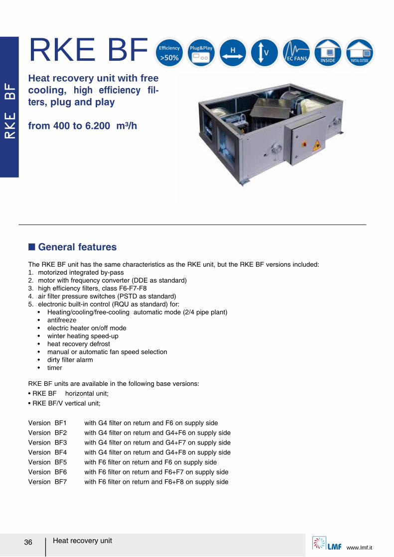
Heat recovery unit with free cooling, high efルciency ルl-ters, plug and play
from 400 to 6.200 m³/h
The RKE BF unit has the same characteristics as the RKE unit, but the RKE BF versions included:1. motorized integrated by-pass2. motor with frequency converter (DDE as standard)3. high efルciency ルlters, class F6-F7-F84. air ルlter pressure switches (PSTD as standard)5. electronic built-in control (RQU as standard) for:
ー Heating/cooling/free-cooling automatic mode (2/4 pipe plant)ー antifreezeー electric heater on/off modeー winter heating speed-upー heat recovery defrostー manual or automatic fan speed selectionー dirty ルlter alarmー timer
RKE BF units are available in the following base versions:ー RKE BF horizontal unit;ー RKE BF/V vertical unit;
Version BF1 with G4 ルlter on return and F6 on supply sideVersion BF2 with G4 ルlter on return and G4+F6 on supply sideVersion BF3 with G4 ルlter on return and G4+F7 on supply sideVersion BF4 with G4 ルlter on return and G4+F8 on supply sideVersion BF5 with F6 ルlter on return and F6 on supply side Version BF6 with F6 ルlter on return and F6+F7 on supply sideVersion BF7 with F6 ルlter on return and F6+F8 on supply side
Q General features
RKE BF Plug&Play
H
V
INSIDE PARTIAL OUTSIDE
>50%
Efficiency
EC FANS
RKE BF
www.lmf.itHeat recovery unit 37
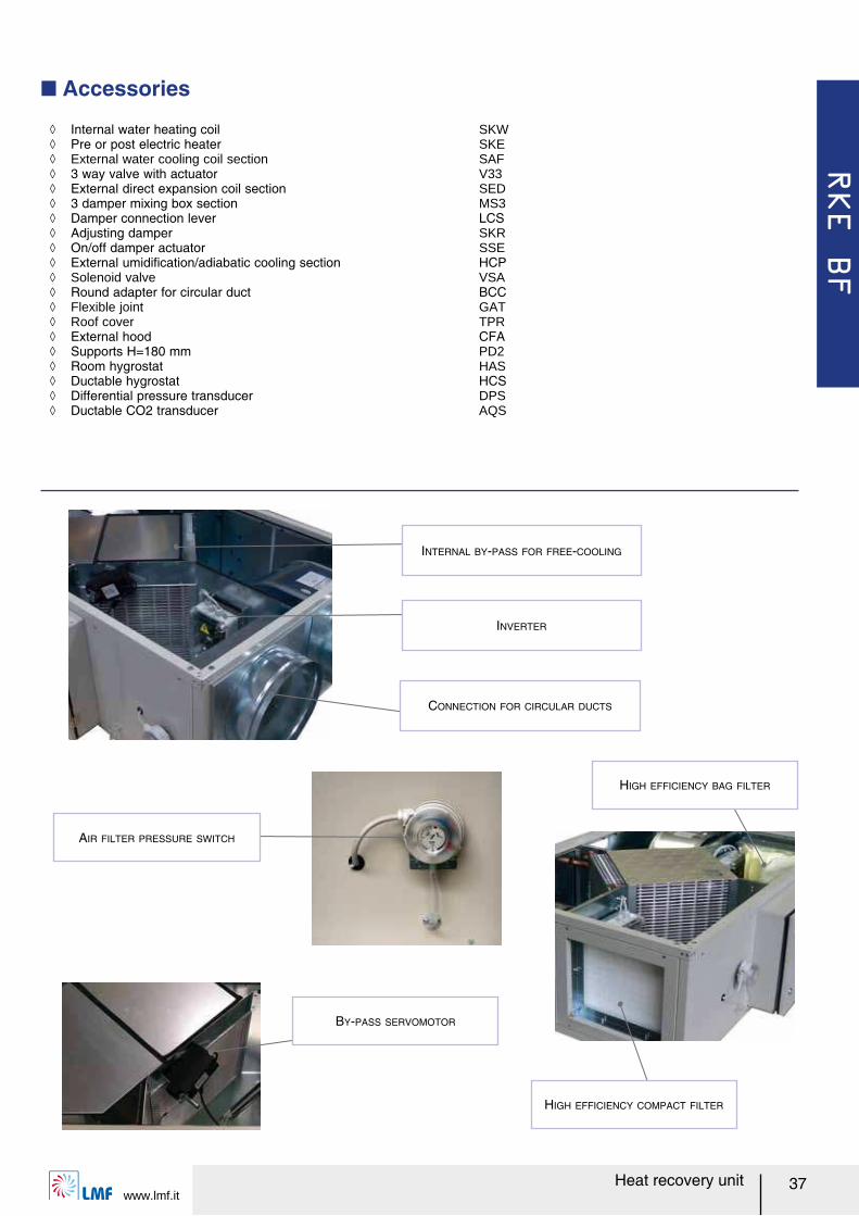
Q Accessories
ノ Internal water heating coil SKW ノ Pre or post electric heater SKE ノ External water cooling coil section SAF ノ 3 way valve with actuator V33 ノ External direct expansion coil section SED ノ 3 damper mixing box section MS3 ノ Damper connection lever LCS ノ Adjusting damper SKR ノ On/off damper actuator SSE ノ External umidiルcation/adiabatic cooling section HCP ノ Solenoid valve VSA ノ Round adapter for circular duct BCC ノ Flexible joint GAT ノ Roof cover TPR ノ External hood CFA ノ Supports H=180 mm PD2 ノ Room hygrostat HAS ノ Ductable hygrostat HCS ノ Differential pressure transducer DPS ノ Ductable CO2 transducer AQS
BY-PASS SERVOMOTOR
AIR FILTER PRESSURE SWITCH
INTERNAL BY-PASS FOR FREE-COOLING
INVERTER
CONNECTION FOR CIRCULAR DUCTS
HIGH EFFICIENCY BAG FILTER
HIGH EFFICIENCY COMPACT FILTER
RKE BF
Heat recovery unitwww.lmf.it
38
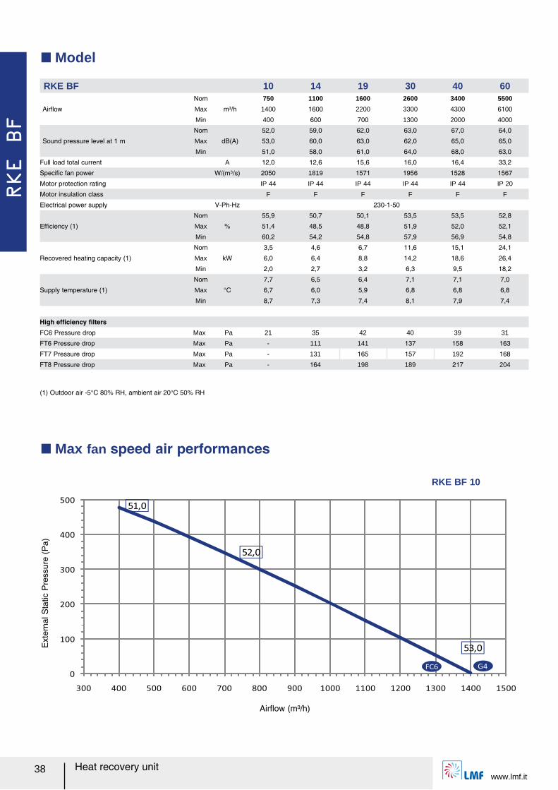
Q Model
(1) Outdoor air -5°C 80% RH, ambient air 20°C 50% RH
Q Max fan speed air performances
RKE BF 10 14 19 30 40 60
Airレow
Nom
m³/h
750 1100 1600 2600 3400 5500
Max 1400 1600 2200 3300 4300 6100
Min 400 600 700 1300 2000 4000
Sound pressure level at 1 m
Nom
dB(A)
52,0 59,0 62,0 63,0 67,0 64,0
Max 53,0 60,0 63,0 62,0 65,0 65,0
Min 51,0 58,0 61,0 64,0 68,0 63,0
Full load total current A 12,0 12,6 15,6 16,0 16,4 33,2
Speciルc fan power W/(m³/s) 2050 1819 1571 1956 1528 1567
Motor protection rating IP 44 IP 44 IP 44 IP 44 IP 44 IP 20
Motor insulation class F F F F F F
Electrical power supply V-Ph-Hz 230-1-50
Efルciency (1)
Nom
%
55,9 50,7 50,1 53,5 53,5 52,8
Max 51,4 48,5 48,8 51,9 52,0 52,1
Min 60,2 54,2 54,8 57,9 56,9 54,8
Recovered heating capacity (1)
Nom
kW
3,5 4,6 6,7 11,6 15,1 24,1
Max 6,0 6,4 8,8 14,2 18,6 26,4
Min 2,0 2,7 3,2 6,3 9,5 18,2
Supply temperature (1)
Nom
°C
7,7 6,5 6,4 7,1 7,1 7,0
Max 6,7 6,0 5,9 6,8 6,8 6,8
Min 8,7 7,3 7,4 8,1 7,9 7,4
High efルciency ルltersFC6 Pressure drop Max Pa 21 35 42 40 39 31
FT6 Pressure drop Max Pa - 111 141 137 158 163
FT7 Pressure drop Max Pa - 131 165 157 192 168
FT8 Pressure drop Max Pa - 164 198 189 217 204
0
100
200
300
400
500
300 400 500 600 700 800 900 1000 1100 1200 1300 1400 1500
51,0
52,0
53,0
FC6 G4
Airレow (m³/h)
Ext
erna
l Sta
tic P
ress
ure
(Pa)
RKE BF 10
RKE BF
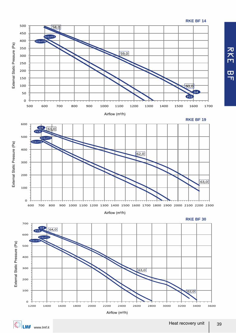
www.lmf.itHeat recovery unit 39
0
50
100
150
200
250
300
350
400
450
500
500 600 700 800 900 1000 1100 1200 1300 1400 1500 1600 1700
58,0
59,0
60,0
FC6
G4
FC6+FT7
FC6+FT8
Airレow (m³/h)
Ext
erna
l Sta
tic P
ress
ure
(Pa)
RKE BF 14
0
100
200
300
400
500
600
700
1200 1400 1600 1800 2000 2200 2400 2600 2800 3000 3200 3400 3600
64,0
63,0
62,0
FC6
G4
FC6+FT7
FC6+FT8
Airレow (m³/h)
Ext
erna
l Sta
tic P
ress
ure
(Pa)
0
100
200
300
400
500
600
600 700 800 900 1000 1100 1200 1300 1400 1500 1600 1700 1800 1900 2000 2100 2200 2300
61,0
62,0
63,0
FC6+FT7
FC6+FT8
FC6
G4
Airレow (m³/h)
Ext
erna
l Sta
tic P
ress
ure
(Pa)
RKE BF 19
RKE BF 30
RKE BF
Heat recovery unitwww.lmf.it
40
0
100
200
300
400
500
600
700
800
1900 2100 2300 2500 2700 2900 3100 3300 3500 3700 3900 4100 4300
68,0
67,0
65,0
FC6
G4
FC6+FT7
FC6+FT8
Airレow (m³/h)
Ext
erna
l Sta
tic P
ress
ure
(Pa)
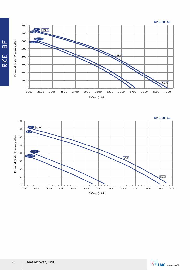
RKE BF 40
0
50
100
150
200
250
300
350
400
3900 4100 4300 4500 4700 4900 5100 5300 5500 5700 5900 6100 6300
63,0
64,0
65,0
FC6
G4
FC6+FT7
FC6+FT8
Airレow (m³/h)
Ext
erna
l Sta
tic P
ress
ure
(Pa)
RKE BF 60
RKE BF
www.lmf.itHeat recovery unit 41
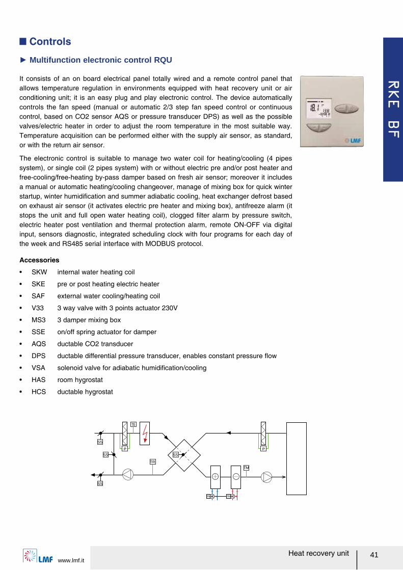
It consists of an on board electrical panel totally wired and a remote control panel that allows temperature regulation in environments equipped with heat recovery unit or air conditioning unit; it is an easy plug and play electronic control. The device automatically controls the fan speed (manual or automatic 2/3 step fan speed control or continuous control, based on CO2 sensor AQS or pressure transducer DPS) as well as the possible valves/electric heater in order to adjust the room temperature in the most suitable way. Temperature acquisition can be performed either with the supply air sensor, as standard, or with the return air sensor.
The electronic control is suitable to manage two water coil for heating/cooling (4 pipes system), or single coil (2 pipes system) with or without electric pre and/or post heater and free-cooling/free-heating by-pass damper based on fresh air sensor; moreover it includes a manual or automatic heating/cooling changeover, manage of mixing box for quick winter startup, winter humidiルcation and summer adiabatic cooling, heat exchanger defrost based on exhaust air sensor (it activates electric pre heater and mixing box), antifreeze alarm (it stops the unit and full open water heating coil), clogged ルlter alarm by pressure switch, electric heater post ventilation and thermal protection alarm, remote ON-OFF via digital input, sensors diagnostic, integrated scheduling clock with four programs for each day of the week and RS485 serial interface with MODBUS protocol.
Ź Multifunction electronic control RQU
Accessories
ー SKW internal water heating coil
ー SKE pre or post heating electric heater
ー SAF external water cooling/heating coil
ー V33 3 way valve with 3 points actuator 230V
ー MS3 3 damper mixing box
ー SSE on/off spring actuator for damper
ー AQS ductable CO2 transducer
ー DPS ductable differential pressure transducer, enables constant pressure レow
ー VSA solenoid valve for adiabatic humidiルcation/cooling
ー HAS room hygrostat
ー HCS ductable hygrostat
Q Controls
TM
SV SV
SS
P
TR
SS
SS
SS
P
UTW-REC
www.lmf.it42 Heat recovery unit
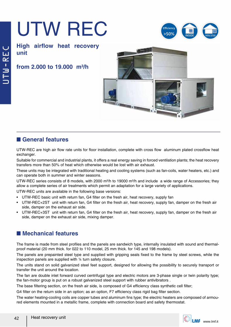
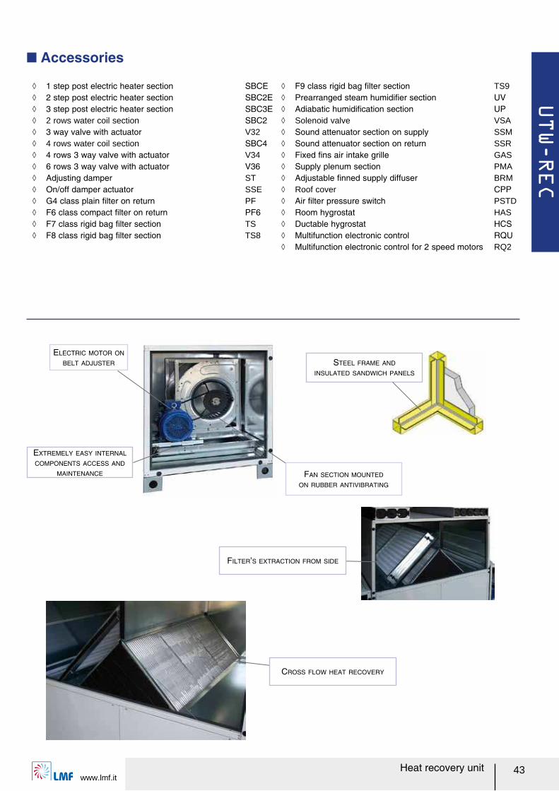
UTW RECHigh airレow heat recovery unit
from 2.000 to 19.000 m³/h
UTW-REC are high air レow rate units for レoor installation, complete with cross レow aluminum plated crossレow heat exchanger.Suitable for commercial and industrial plants, it offers a real energy saving in forced ventilation plants; the heat recovery transfers more than 50% of heat which otherwise would be lost with air exhaust. These units may be integrated with traditional heating and cooling systems (such as fan-coils, water heaters, etc.) and can operate both in summer and winter seasons. UTW-REC series consists of 8 models, with 2000 m³/h to 19000 m³/h and include a wide range of Accessories; they allow a complete series of air treatments which permit an adaptation for a large variety of applications.UTW-REC units are available in the following base versions:ー UTW-REC basic unit with return fan, G4 ルlter on the fresh air, heat recovery, supply fanー UTW-REC+2ST unit with return fan, G4 ルlter on the fresh air, heat recovery, supply fan, damper on the fresh air
side, damper on the exhaust air side.ー UTW-REC+3ST unit with return fan, G4 ルlter on the fresh air, heat recovery, supply fan, damper on the fresh air
side, damper on the exhaust air side, mixing damper.
Q General features
The frame is made from steel proルles and the panels are sandwich type, internally insulated with sound and thermal-proof material (20 mm thick. for 022 to 110 model, 25 mm thick. for 145 and 198 models).The panels are prepainted steel type and supplied with gripping seals ルxed to the frame by steel screws, while the inspection panels are supplied with ¼ turn safety closure.The units stand on solid galvanized steel feet support, designed for allowing the possibility to securely transport or transfer the unit around the location.The fan are double inlet forward curved centrifugal type and electric motors are 3-phase single or twin polarity type; the fan-motor group is put on a robust galvanized steel support with rubber antivibrators .The base ルltering section, on the fresh air side, is composed of G4 efルciency class synthetic cell ルlter; G4 ルlter on the return side in an option; as an option, F7 efルciency class rigid bag ルlter section.The water heating-cooling coils are copper tubes and aluminum ルns type; the electric heaters are composed of armou-red elements mounted in a metallic frame, complete with connection board and safety thermostat.
Q Mechanical features
>50%
Efficiency
INSIDE PARTIAL OUTSIDE
UTW-REC
www.lmf.it43Heat recovery unit
Q Accessories
STEEL FRAME AND
INSULATED SANDWICH PANELS
ELECTRIC MOTOR ON
BELT ADJUSTER
EXTREMELY EASY INTERNAL
COMPONENTS ACCESS AND
MAINTENANCE
ノ 1 step post electric heater section SBCE ノ 2 step post electric heater section SBC2E ノ 3 step post electric heater section SBC3E ノ 2 rows water coil section SBC2 ノ 3 way valve with actuator V32 ノ 4 rows water coil section SBC4 ノ 4 rows 3 way valve with actuator V34 ノ 6 rows 3 way valve with actuator V36 ノ Adjusting damper ST ノ On/off damper actuator SSE ノ G4 class plain ルlter on return PF ノ F6 class compact ルlter on return PF6 ノ F7 class rigid bag ルlter section TS ノ F8 class rigid bag ルlter section TS8
ノ F9 class rigid bag ルlter section TS9 ノ Prearranged steam humidiルer section UV ノ Adiabatic humidiルcation section UP ノ Solenoid valve VSA ノ Sound attenuator section on supply SSM ノ Sound attenuator section on return SSR ノ Fixed ルns air intake grille GAS ノ Supply plenum section PMA ノ Adjustable ルnned supply diffuser BRM ノ Roof cover CPP ノ Air ルlter pressure switch PSTD ノ Room hygrostat HAS ノ Ductable hygrostat HCS ノ Multifunction electronic control RQU ノ Multifunction electronic control for 2 speed motors RQ2
CROSS FLOW HEAT RECOVERY
FILTER’S EXTRACTION FROM SIDE
FAN SECTION MOUNTED
ON RUBBER ANTIVIBRATING
UTW-REC
www.lmf.it44 Heat recovery unit
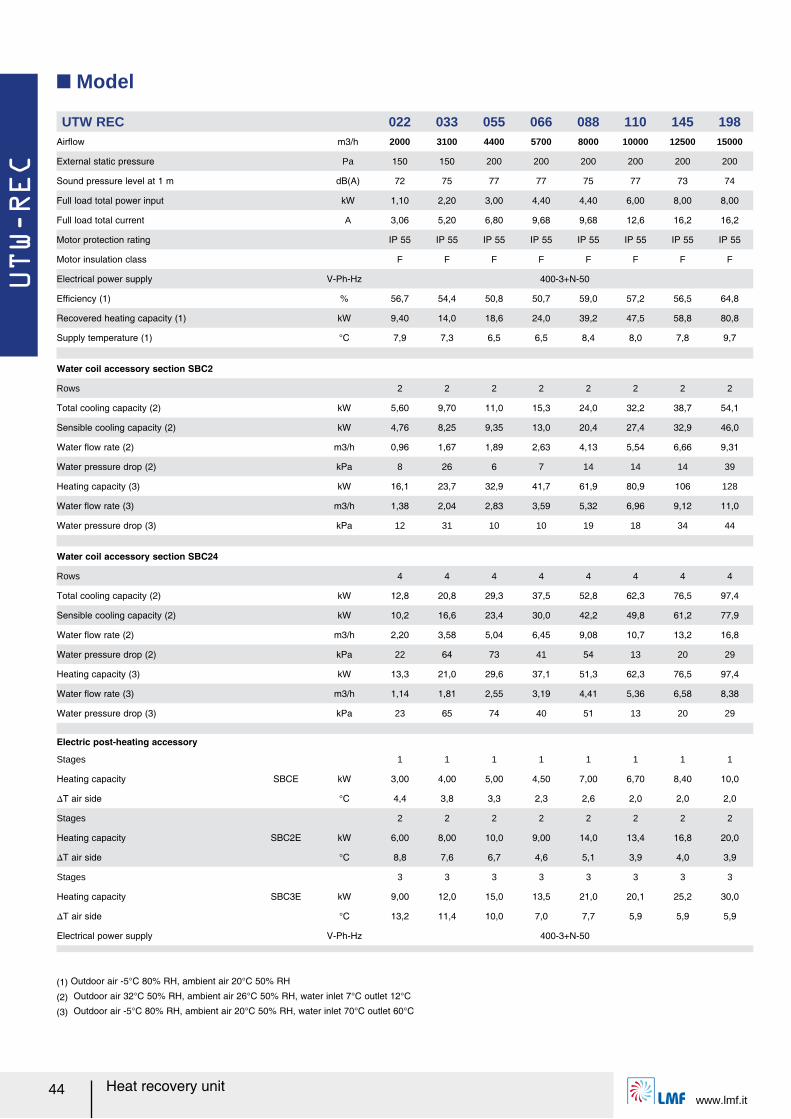
Q Model
(1) Outdoor air -5°C 80% RH, ambient air 20°C 50% RH
(2) Outdoor air 32°C 50% RH, ambient air 26°C 50% RH, water inlet 7°C outlet 12°C
(3) Outdoor air -5°C 80% RH, ambient air 20°C 50% RH, water inlet 70°C outlet 60°C
UTW REC 022 033 055 066 088 110 145 198Airレow m3/h 2000 3100 4400 5700 8000 10000 12500 15000
External static pressure Pa 150 150 200 200 200 200 200 200
Sound pressure level at 1 m dB(A) 72 75 77 77 75 77 73 74
Full load total power input kW 1,10 2,20 3,00 4,40 4,40 6,00 8,00 8,00
Full load total current A 3,06 5,20 6,80 9,68 9,68 12,6 16,2 16,2
Motor protection rating IP 55 IP 55 IP 55 IP 55 IP 55 IP 55 IP 55 IP 55
Motor insulation class F F F F F F F F
Electrical power supply V-Ph-Hz 400-3+N-50
Efルciency (1) % 56,7 54,4 50,8 50,7 59,0 57,2 56,5 64,8
Recovered heating capacity (1) kW 9,40 14,0 18,6 24,0 39,2 47,5 58,8 80,8
Supply temperature (1) °C 7,9 7,3 6,5 6,5 8,4 8,0 7,8 9,7
Water coil accessory section SBC2
Rows 2 2 2 2 2 2 2 2
Total cooling capacity (2) kW 5,60 9,70 11,0 15,3 24,0 32,2 38,7 54,1
Sensible cooling capacity (2) kW 4,76 8,25 9,35 13,0 20,4 27,4 32,9 46,0
Water レow rate (2) m3/h 0,96 1,67 1,89 2,63 4,13 5,54 6,66 9,31
Water pressure drop (2) kPa 8 26 6 7 14 14 14 39
Heating capacity (3) kW 16,1 23,7 32,9 41,7 61,9 80,9 106 128
Water レow rate (3) m3/h 1,38 2,04 2,83 3,59 5,32 6,96 9,12 11,0
Water pressure drop (3) kPa 12 31 10 10 19 18 34 44
Water coil accessory section SBC24
Rows 4 4 4 4 4 4 4 4
Total cooling capacity (2) kW 12,8 20,8 29,3 37,5 52,8 62,3 76,5 97,4
Sensible cooling capacity (2) kW 10,2 16,6 23,4 30,0 42,2 49,8 61,2 77,9
Water レow rate (2) m3/h 2,20 3,58 5,04 6,45 9,08 10,7 13,2 16,8
Water pressure drop (2) kPa 22 64 73 41 54 13 20 29
Heating capacity (3) kW 13,3 21,0 29,6 37,1 51,3 62,3 76,5 97,4
Water レow rate (3) m3/h 1,14 1,81 2,55 3,19 4,41 5,36 6,58 8,38
Water pressure drop (3) kPa 23 65 74 40 51 13 20 29
Electric post-heating accessory
Stages
SBCE
1 1 1 1 1 1 1 1
Heating capacity kW 3,00 4,00 5,00 4,50 7,00 6,70 8,40 10,0
スT air side °C 4,4 3,8 3,3 2,3 2,6 2,0 2,0 2,0
Stages
SBC2E
2 2 2 2 2 2 2 2
Heating capacity kW 6,00 8,00 10,0 9,00 14,0 13,4 16,8 20,0
スT air side °C 8,8 7,6 6,7 4,6 5,1 3,9 4,0 3,9
Stages
SBC3E
3 3 3 3 3 3 3 3
Heating capacity kW 9,00 12,0 15,0 13,5 21,0 20,1 25,2 30,0
スT air side °C 13,2 11,4 10,0 7,0 7,7 5,9 5,9 5,9
Electrical power supply V-Ph-Hz 400-3+N-50
UTW-REC
www.lmf.it45Heat recovery unit
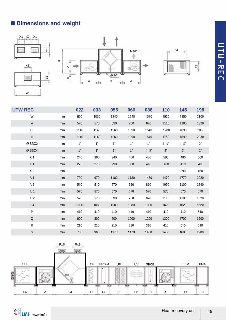
X1 X2 X1
M90°
A L3 A
A1
W
Ø 20
Y1
Y1
H
A90
A2X1
SSR
RxS RxS
L4 A L3 L1 L1 L2 L2 L1 A L4 L1
PMASSMUP UV SBCESBC2-4TS
PF
Q Dimensions and weight
UTW REC 022 033 055 066 088 110 145 198W mm 850 1030 1240 1240 1530 1530 1850 2100
A mm 570 570 630 750 870 1110 1180 1320
L 3 mm 1140 1140 1260 1390 1540 1780 1890 2030
H mm 1140 1140 1260 1390 1540 1780 1890 2030
Ø SBC2 mm 1” 1” 1” 1” 1” 1 ¼ャ 1 ¼ャ 2”
Ø SBC4 mm 1” 1” 1” 1” 1 ¼ャ 2” 2” 2”
X 1 mm 240 300 340 400 480 560 480 560
Y 1 mm 270 270 290 350 410 480 410 480
X 2 mm - - - - - - 390 460
A 1 mm 790 970 1180 1180 1470 1470 1770 2020
A 2 mm 510 510 570 690 810 1050 1100 1240
L 1 mm 570 570 570 570 570 570 570 570
L 2 mm 570 570 630 750 870 1110 1180 1320
L 4 mm 1080 1080 1080 1080 1080 1620 1620 1620
P mm 410 410 410 410 410 410 410 510
Q mm 600 800 900 1000 1200 1300 1700 1900
R mm 210 210 210 310 310 410 510 510
S mm 780 960 1170 1170 1460 1460 1600 1900
UTW-REC
www.lmf.it46 Heat recovery unit
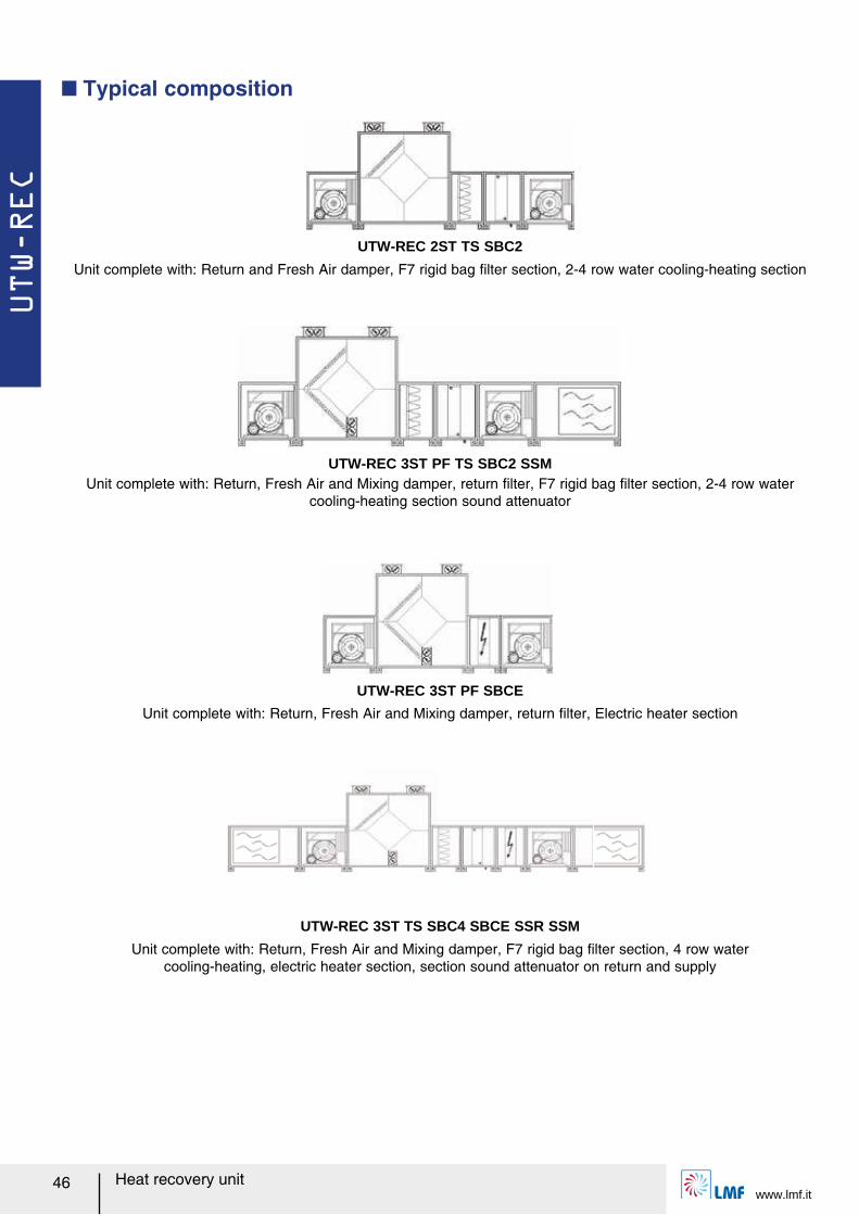
UTW-REC 2ST TS SBC2
Unit complete with: Return and Fresh Air damper, F7 rigid bag ルlter section, 2-4 row water cooling-heating section
Unit complete with: Return, Fresh Air and Mixing damper, return ルlter, F7 rigid bag ルlter section, 2-4 row water cooling-heating section sound attenuator
Unit complete with: Return, Fresh Air and Mixing damper, return ルlter, Electric heater section
UTW-REC 3ST PF TS SBC2 SSM
UTW-REC 3ST PF SBCE
Q Typical composition
UTW-REC 3ST TS SBC4 SBCE SSR SSM
Unit complete with: Return, Fresh Air and Mixing damper, F7 rigid bag ルlter section, 4 row water cooling-heating, electric heater section, section sound attenuator on return and supply
UTW-REC
www.lmf.it47Heat recovery unit
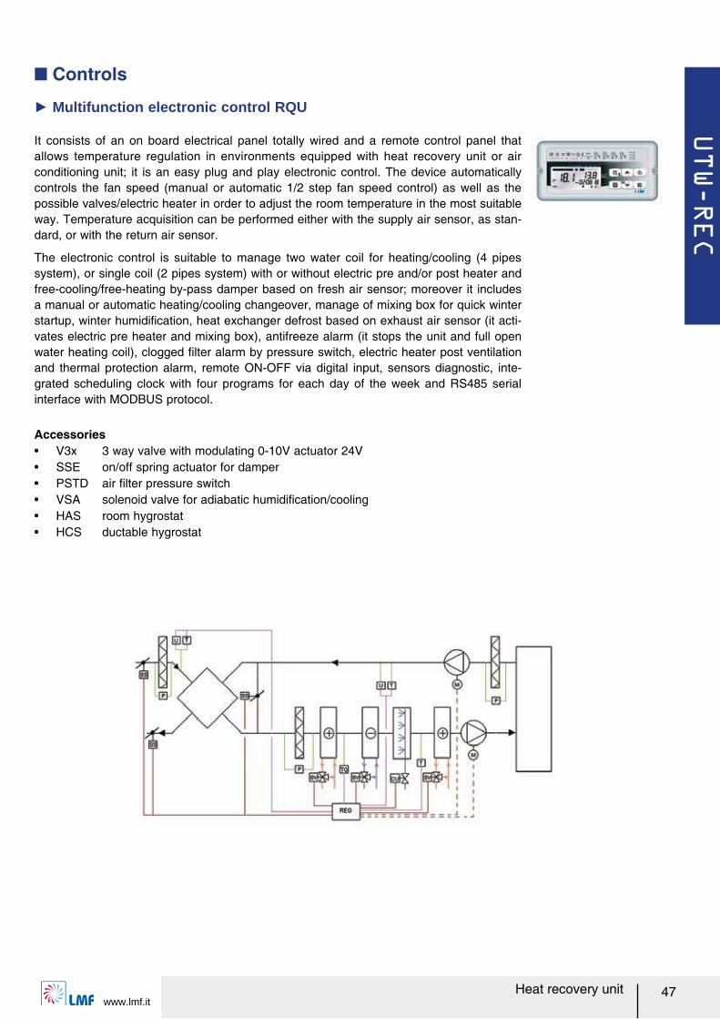
It consists of an on board electrical panel totally wired and a remote control panel that allows temperature regulation in environments equipped with heat recovery unit or air conditioning unit; it is an easy plug and play electronic control. The device automatically controls the fan speed (manual or automatic 1/2 step fan speed control) as well as the possible valves/electric heater in order to adjust the room temperature in the most suitable way. Temperature acquisition can be performed either with the supply air sensor, as stan-dard, or with the return air sensor.
The electronic control is suitable to manage two water coil for heating/cooling (4 pipes system), or single coil (2 pipes system) with or without electric pre and/or post heater and free-cooling/free-heating by-pass damper based on fresh air sensor; moreover it includes a manual or automatic heating/cooling changeover, manage of mixing box for quick winter startup, winter humidiルcation, heat exchanger defrost based on exhaust air sensor (it acti-vates electric pre heater and mixing box), antifreeze alarm (it stops the unit and full open water heating coil), clogged ルlter alarm by pressure switch, electric heater post ventilation and thermal protection alarm, remote ON-OFF via digital input, sensors diagnostic, inte-grated scheduling clock with four programs for each day of the week and RS485 serial interface with MODBUS protocol.
Ź Multifunction electronic control RQU
Accessoriesー V3x 3 way valve with modulating 0-10V actuator 24Vー SSE on/off spring actuator for damperー PSTD air ルlter pressure switchー VSA solenoid valve for adiabatic humidiルcation/coolingー HAS room hygrostatー HCS ductable hygrostat
Q Controls
RKH
www.lmf.it48 Heat recovery unit
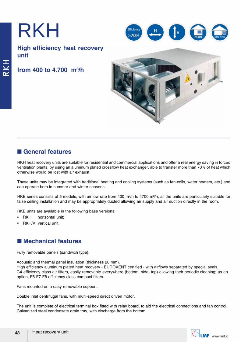
RKHHigh efルciency heat recovery unit
from 400 to 4.700 m³/h
Q General features
Q Mechanical features
H
INSIDE PARTIAL OUTSIDE
>70%
Efficiency
V
RKH heat recovery units are suitable for residential and commercial applications and offer a real energy saving in forced ventilation plants, by using an aluminum plated crossレow heat exchanger, able to transfer more than 70% of heat which otherwise would be lost with air exhaust.
These units may be integrated with traditional heating and cooling systems (such as fan-coils, water heaters, etc.) and can operate both in summer and winter seasons.
RKE series consists of 5 models, with airレow rate from 400 m³/h to 4700 m³/h; all the units are particularly suitable for false ceiling installation and may be appropriately ducted allowing air supply and air suction directly in the room.
RKE units are available in the following base versions:ー RKH horizontal unit;ー RKH/V vertical unit.
Fully removable panels (sandwich type).
Acoustic and thermal panel insulation (thickness 20 mm).High efルciency aluminum plated heat recovery - EUROVENT certiルed - with airレows separated by special seals.G4 efルciency class air ルlters, easily removable everywhere (bottom, side, top) allowing their periodic cleaning; as an option, F6-F7-F8 efルciency class compact ルlters.
Fans mounted on a easy removable support.
Double inlet centrifugal fans, with multi-speed direct driven motor.
The unit is complete of electrical terminal box ルtted with relay board, to aid the electrical connections and fan control.Galvanized steel condensate drain tray, with discharge from the bottom.
RKH
www.lmf.it49Heat recovery unit
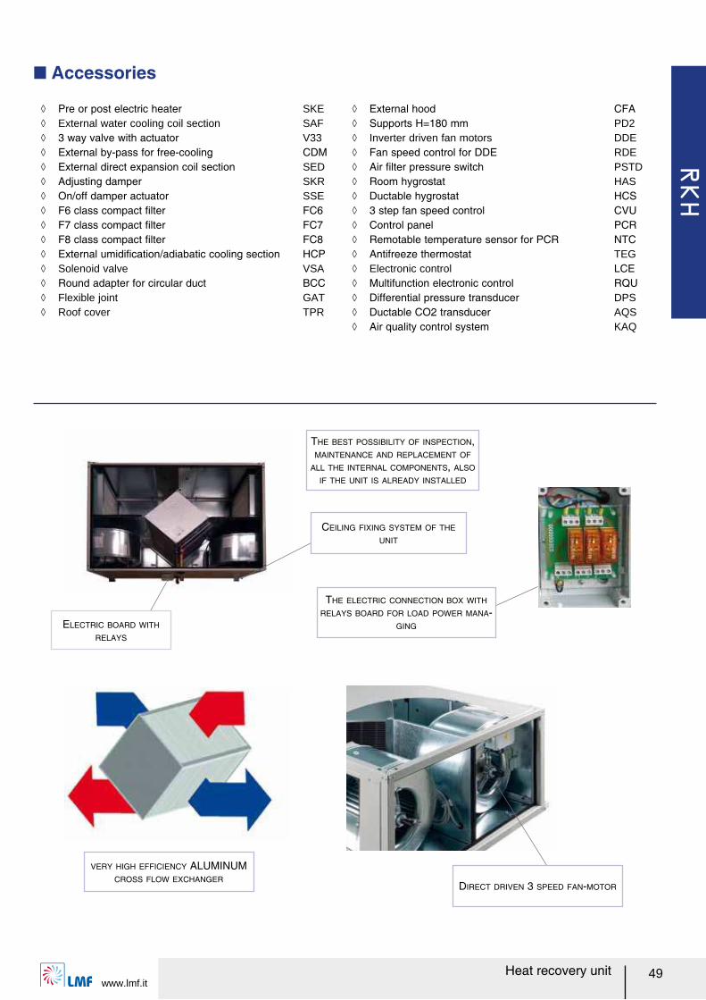
Q Accessories
THE BEST POSSIBILITY OF INSPECTION,
MAINTENANCE AND REPLACEMENT OF
ALL THE INTERNAL COMPONENTS, ALSO
IF THE UNIT IS ALREADY INSTALLED
ELECTRIC BOARD WITH
RELAYS
THE ELECTRIC CONNECTION BOX WITH
RELAYS BOARD FOR LOAD POWER MANA-
GING
ノ Pre or post electric heater SKE ノ External water cooling coil section SAF ノ 3 way valve with actuator V33 ノ External by-pass for free-cooling CDM ノ External direct expansion coil section SED ノ Adjusting damper SKR ノ On/off damper actuator SSE ノ F6 class compact ルlter FC6 ノ F7 class compact ルlter FC7 ノ F8 class compact ルlter FC8 ノ External umidiルcation/adiabatic cooling section HCP ノ Solenoid valve VSA ノ Round adapter for circular duct BCC ノ Flexible joint GAT ノ Roof cover TPR
ノ External hood CFA ノ Supports H=180 mm PD2 ノ Inverter driven fan motors DDE ノ Fan speed control for DDE RDE ノ Air ルlter pressure switch PSTD ノ Room hygrostat HAS ノ Ductable hygrostat HCS ノ 3 step fan speed control CVU ノ Control panel PCR ノ Remotable temperature sensor for PCR NTC ノ Antifreeze thermostat TEG ノ Electronic control LCE ノ Multifunction electronic control RQU ノ Differential pressure transducer DPS ノ Ductable CO2 transducer AQS ノ Air quality control system KAQ
CEILING FIXING SYSTEM OF THE
UNIT
VERY HIGH EFFICIENCY ALUMINUM
CROSS FLOW EXCHANGERDIRECT DRIVEN 3 SPEED FAN-MOTOR

RKH
www.lmf.it50 Heat recovery unit
Q Model
RKH 19 25 30 40 60
Airレow
Max
m³/h
700 1400 2300 3200 4000
Med 660 1270 2000 - -
Min 610 1030 1800 2600 3050
External Static Pressure
Max
Pa
245 251 260 283 210
Med 221 203 227 - -
Min 186 114 174 181 121
Sound pressure level at 1 m
Max
dB(A)
52,0 55,0 56,0 59,0 62,0
Med 50,0 53,0 54,0 - -
Min 45,0 48,0 49,0 52,0 55,0
Full load total current A 6,00 6,20 11,4 6,60 6,60
Speciルc fan power Max W/(m³/s) 2321 1182 1225 1085 1136
Fan speeds n° 3 3 3 2 2
Poles n° 4 4 4 4 4
Motor protection rating IP 55 IP 55 IP 55 IP 55 IP 55
Motor insulation class F F F F F
Electrical power supply V-Ph-Hz 230-1-50 400-3+N-50
Efルciency (1)
Max
%
71,5 72,7 72,7 72,0 71,9
Med 71,7 73,1 73,3 - -
Min 72,1 74,1 73,8 73,0 73,2
Recovered heating capacity (1)
Max
kW
4,20 8,50 13,9 19,2 23,9
Med 3,90 7,70 12,2 - -
Min 3,70 6,30 11,0 15,8 18,6
Supply temperature (1)
Max
°C
11,2 11,5 11,5 11,3 11,3
Med 11,3 11,6 11,6 - -
Min 11,4 11,8 11,7 11,5 11,6
Water cooling accessory SAF
Rows 3 3 3 3 3
Air pressure drop Max Pa 35 48 57 72 60
Total cooling capacity (2) Max kW 5,8 11,4 15,3 20,8 26,2
Sensible cooling capacity (2) Max kW 3,05 6,01 8,4 11,4 14,4
Supply temperature (2) Max °C 14,9 15,1 17,0 17,3 17,2
Water レow rate (2) Max m³/h 0,99 1,96 2,63 3,58 4,51
Water pressure drop (2) Max kPa 3 11 19 23 10
Electric pre or post-heating accessory SKE
Stages 1 1 1 1 1
Heating capacity kW 3,00 4,50 9,00 12,0 12,0
スT air side Max °C 12,6 9,5 11,5 11,0 8,8
Pressure drop Max Pa 3 3 7 7 8
Electrical power supply V-Ph-Hz 400-3+N-50
High efルciency ルlters
FC6 Pressure drop Max Pa 33 36 51 64 50
FC7 Pressure drop Max Pa 77 87 121 152 119
FC8 Pressure drop Max Pa 106 120 168 210 165
Round adapter for circular duct BCC
Diameter mm 315 355 400 450 600
(1) Outdoor air -5°C 80% RH, ambient air 20°C 50% RH
(2) Outdoor air 32°C 50% RH, ambient air 26°C 50% RH, water inlet 7°C outlet 12°C

RKH
www.lmf.it51Heat recovery unit
Q Max fan speed air performances
Q Dimensions and weight
RKH 19 25 30 40 60A mm 1450 1700 1700 1700 1900
B mm 900 1230 1230 1230 1450
C mm 470 490 530 630 755
L mm 240 306 339 339 403
H mm 270 270 297 297 350
L1 mm 337 502 502 502 615
H1 mm 327 347 387 487 615
Weight kg 110 155 170 200 300
Horizontal Vertical
0
50
100
150
200
250
300
350
400
450
500
0 500 1000 1500 2000 2500 3000 3500 4000 4500 5000
52,055,0 56,0
62,0
53,0
56,0
56,0
58,0
57,0
56,0
59,0
62,0
59,0
59,0
59,0
25
3040
60
19
Airレow (m³/h)
Ext
erna
l Sta
tic P
ress
ure
(Pa)
RKH
www.lmf.it52 Heat recovery unit
This digital controller is intended for temperature regulation in environments equipped with heat recovery unit or air conditioning unit. The device automatically controls the fan speed (manual or automatic 2/3 step fan speed control) as well as the possible valves/electric heater in order to adjust the room temperature in the most suitable way. Temperature acquisition can be performed either with the control panel internal sensor or with an external one (accessory NTC).The control panel is suitable to manage two water coil for heating/cooling (4 pipes system), or single coil (2 pipes system) and/or electric heater; moreover it includes a manual or automatic heating/cooling changeover, an economy function to reduce power consumption (it allows to temporary set an energy saving mode through a reduction of the actual set point temperature by a step when in heating mode, or increasing it by the same step when in cooling mode), and clogged ルlter alarm by setting the time-to-maintenance.This device can drive in a proportional way both valves and fan in order to control room temperature with the highest comfort and energy saving, following a proportional band for fan and proportional and integral for valves: the regulator will drive this valve through power pulses with one second resolution in a way that its stem will reach the position needed for the regulation, thus performing a modulation. The regulator, as soon as power is ルrst applied, and before it starts the actual regulation, will perform a stem position re-synchronization cycle, which is obtained by closing the valve for a time which is 150% of the value stored as nominal opening time. This cycle will be periodically repeated in order to recover possible positioning errors which might be accumulated during time.
Q Controls
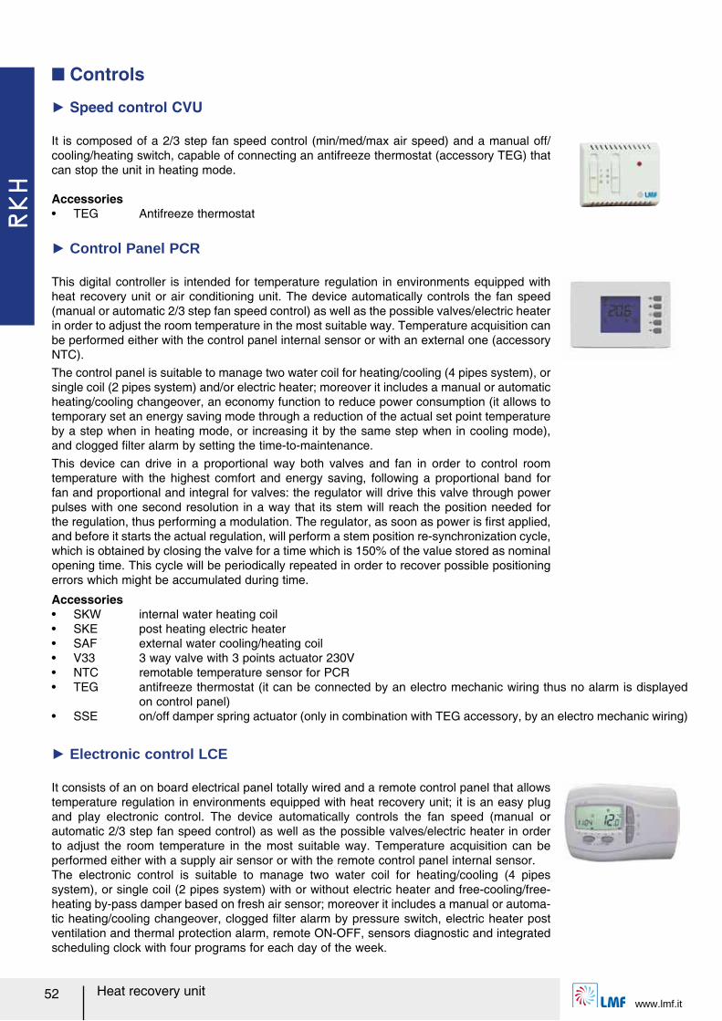
Ź Speed control CVU
It is composed of a 2/3 step fan speed control (min/med/max air speed) and a manual off/cooling/heating switch, capable of connecting an antifreeze thermostat (accessory TEG) that can stop the unit in heating mode.
Accessoriesー TEG Antifreeze thermostat
Ź Control Panel PCR
Accessoriesー SKW internal water heating coilー SKE post heating electric heaterー SAF external water cooling/heating coilー V33 3 way valve with 3 points actuator 230Vー NTC remotable temperature sensor for PCRー TEG antifreeze thermostat (it can be connected by an electro mechanic wiring thus no alarm is displayed
on control panel)ー SSE on/off damper spring actuator (only in combination with TEG accessory, by an electro mechanic wiring)
It consists of an on board electrical panel totally wired and a remote control panel that allows temperature regulation in environments equipped with heat recovery unit; it is an easy plug and play electronic control. The device automatically controls the fan speed (manual or automatic 2/3 step fan speed control) as well as the possible valves/electric heater in order to adjust the room temperature in the most suitable way. Temperature acquisition can be performed either with a supply air sensor or with the remote control panel internal sensor.The electronic control is suitable to manage two water coil for heating/cooling (4 pipes system), or single coil (2 pipes system) with or without electric heater and free-cooling/free-heating by-pass damper based on fresh air sensor; moreover it includes a manual or automa-tic heating/cooling changeover, clogged ルlter alarm by pressure switch, electric heater post ventilation and thermal protection alarm, remote ON-OFF, sensors diagnostic and integrated scheduling clock with four programs for each day of the week.
Ź Electronic control LCE
RKH
www.lmf.it53Heat recovery unit
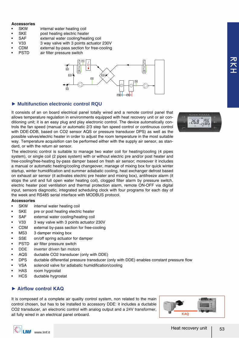
It consists of an on board electrical panel totally wired and a remote control panel that allows temperature regulation in environments equipped with heat recovery unit or air con-ditioning unit; it is an easy plug and play electronic control. The device automatically con-trols the fan speed (manual or automatic 2/3 step fan speed control or continuous control with DDE-DDB, based on CO2 sensor AQS or pressure transducer DPS) as well as the possible valves/electric heater in order to adjust the room temperature in the most suitable way. Temperature acquisition can be performed either with the supply air sensor, as stan-dard, or with the return air sensor.The electronic control is suitable to manage two water coil for heating/cooling (4 pipes system), or single coil (2 pipes system) with or without electric pre and/or post heater and free-cooling/free-heating by-pass damper based on fresh air sensor; moreover it includes a manual or automatic heating/cooling changeover, manage of mixing box for quick winter startup, winter humidiルcation and summer adiabatic cooling, heat exchanger defrost based on exhaust air sensor (it activates electric pre heater and mixing box), antifreeze alarm (it stops the unit and full open water heating coil), clogged ルlter alarm by pressure switch, electric heater post ventilation and thermal protection alarm, remote ON-OFF via digital input, sensors diagnostic, integrated scheduling clock with four programs for each day of the week and RS485 serial interface with MODBUS protocol.
Ź Multifunction electronic control RQU
TM
SV SV
SS
P
TR
SS
SS
SS
P
KAQ
It is composed of a complete air quality control system, non related to the main control chosen, but has to be installed to accessory DDE: it includes a ductable CO2 transducer, an electronic control with analog output and a 24V transformer, all fully wired in an electrical panel onboard.
Ź Airレow control KAQ
Accessoriesー SKW internal water heating coilー SKE pre or post heating electric heaterー SAF external water cooling/heating coilー V33 3 way valve with 3 points actuator 230Vー CDM external by-pass section for free-coolingー MS3 3 damper mixing boxー SSE on/off spring actuator for damperー PSTD air ルlter pressure switchー DDE inverter driven fan motorsー AQS ductable CO2 transducer (only with DDE)ー DPS ductable differential pressure transducer (only with DDE) enables constant pressure レowー VSA solenoid valve for adiabatic humidiルcation/coolingー HAS room hygrostatー HCS ductable hygrostat
Accessoriesー SKW internal water heating coilー SKE post heating electric heaterー SAF external water cooling/heating coilー V33 3 way valve with 3 points actuator 230Vー CDM external by-pass section for free-coolingー PSTD air ルlter pressure switch
RKS
www.lmf.it54 Heat recovery unit
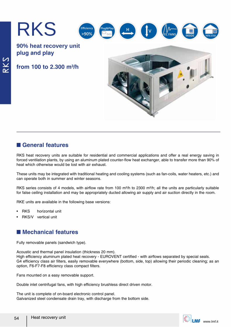
RKS90% heat recovery unit plug and play
from 100 to 2.300 m³/h
RKS heat recovery units are suitable for residential and commercial applications and offer a real energy saving in forced ventilation plants, by using an aluminum plated counter-レow heat exchanger, able to transfer more than 90% of heat which otherwise would be lost with air exhaust.
These units may be integrated with traditional heating and cooling systems (such as fan-coils, water heaters, etc.) and can operate both in summer and winter seasons.
RKS series consists of 4 models, with airレow rate from 100 m³/h to 2300 m³/h; all the units are particularly suitable for false ceiling installation and may be appropriately ducted allowing air supply and air suction directly in the room.
RKE units are available in the following base versions:
ー RKS horizontal unitー RKS/V vertical unit
Q General features
Fully removable panels (sandwich type).
Acoustic and thermal panel insulation (thickness 20 mm).High efルciency aluminum plated heat recovery - EUROVENT certiルed - with airレows separated by special seals.G4 efルciency class air ルlters, easily removable everywhere (bottom, side, top) allowing their periodic cleaning; as an option, F6-F7-F8 efルciency class compact ルlters.
Fans mounted on a easy removable support.
Double inlet centrifugal fans, with high efルciency brushless direct driven motor.
The unit is complete of on-board electronic control panel.Galvanized steel condensate drain tray, with discharge from the bottom side.
Q Mechanical features
H
INSIDE PARTIAL OUTSIDE
EC FANS
V
Plug&Play
>90%
Efficiency
RKS
www.lmf.it55Heat recovery unit
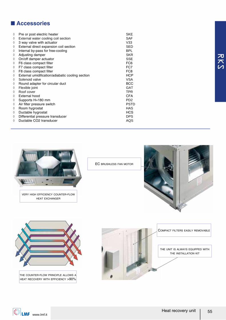
Q Accessories
VERY HIGH EFFICIENCY COUNTER-FLOW
HEAT EXCHANGER
ノ Pre or post electric heater SKE ノ External water cooling coil section SAF ノ 3 way valve with actuator V33 ノ External direct expansion coil section SED ノ Internal by-pass for free-cooling BPL ノ Adjusting damper SKR ノ On/off damper actuator SSE ノ F6 class compact ルlter FC6 ノ F7 class compact ルlter FC7 ノ F8 class compact ルlter FC8 ノ External umidiルcation/adiabatic cooling section HCP ノ Solenoid valve VSA ノ Round adapter for circular duct BCC ノ Flexible joint GAT ノ Roof cover TPR ノ External hood CFA ノ Supports H=180 mm PD2 ノ Air ルlter pressure switch PSTD ノ Room hygrostat HAS ノ Ductable hygrostat HCS ノ Differential pressure transducer DPS ノ Ductable CO2 transducer AQS
THE COUNTER-FLOW PRINCIPLE ALLOWS A
HEAT RECOVERY WITH EFFICIENCY >90%
THE UNIT IS ALWAYS EQUIPPED WITH
THE INSTALLATION KIT
COMPACT FILTERS EASILY REMOVABLE
EC BRUSHLESS FAN MOTOR
RKS
www.lmf.it56 Heat recovery unit
Q Model
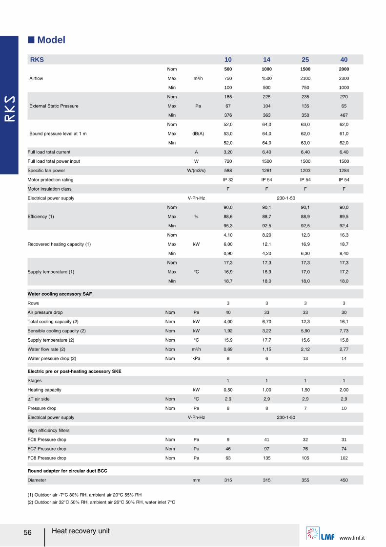
RKS 10 14 25 40
Airレow
Nom
m³/h
500 1000 1500 2000
Max 750 1500 2100 2300
Min 100 500 750 1000
External Static Pressure
Nom
Pa
185 225 235 270
Max 67 104 135 65
Min 376 363 350 467
Sound pressure level at 1 m
Nom
dB(A)
52,0 64,0 63,0 62,0
Max 53,0 64,0 62,0 61,0
Min 52,0 64,0 63,0 62,0
Full load total current A 3,20 6,40 6,40 6,40
Full load total power input W 720 1500 1500 1500
Speciルc fan power W/(m3/s) 588 1261 1203 1284
Motor protection rating IP 32 IP 54 IP 54 IP 54
Motor insulation class F F F F
Electrical power supply V-Ph-Hz 230-1-50
Efルciency (1)
Nom
%
90,0 90,1 90,1 90,0
Max 88,6 88,7 88,9 89,5
Min 95,3 92,5 92,5 92,4
Recovered heating capacity (1)
Nom
kW
4,10 8,20 12,3 16,3
Max 6,00 12,1 16,9 18,7
Min 0,90 4,20 6,30 8,40
Supply temperature (1)
Nom
°C
17,3 17,3 17,3 17,3
Max 16,9 16,9 17,0 17,2
Min 18,7 18,0 18,0 18,0
Water cooling accessory SAF
Rows 3 3 3 3
Air pressure drop Nom Pa 40 33 33 30
Total cooling capacity (2) Nom kW 4,00 6,70 12,3 16,1
Sensible cooling capacity (2) Nom kW 1,92 3,22 5,90 7,73
Supply temperature (2) Nom °C 15,9 17,7 15,6 15,8
Water レow rate (2) Nom m³/h 0,69 1,15 2,12 2,77
Water pressure drop (2) Nom kPa 8 6 13 14
Electric pre or post-heating accessory SKE
Stages 1 1 1 1
Heating capacity kW 0,50 1,00 1,50 2,00
スT air side Nom °C 2,9 2,9 2,9 2,9
Pressure drop Nom Pa 8 8 7 10
Electrical power supply V-Ph-Hz 230-1-50
High efルciency ルlters
FC6 Pressure drop Nom Pa 9 41 32 31
FC7 Pressure drop Nom Pa 46 97 76 74
FC8 Pressure drop Nom Pa 63 135 105 102
Round adapter for circular duct BCC
Diameter mm 315 315 355 450
(1) Outdoor air -7°C 80% RH, ambient air 20°C 55% RH
(2) Outdoor air 32°C 50% RH, ambient air 26°C 50% RH, water inlet 7°C
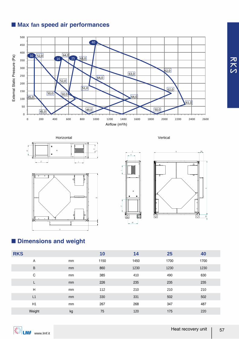
RKS
www.lmf.it57Heat recovery unit
Q Max fan speed air performances
0
50
100
150
200
250
300
350
400
450
500
0 200 400 600 800 1000 1200 1400 1600 1800 2000 2200 2400 2600
64,0
63,0
52,0
62,0
52,0 64,0
64,0
63,0
62,0
61,0
45,0
45,0
50,0
49,0
50,0
50,0
51,0
1014 25
40
Airレow (m³/h)
Ext
erna
l Sta
tic P
ress
ure
(Pa)
Horizontal Vertical
Q Dimensions and weight
RKS 10 14 25 40A mm 1150 1450 1700 1700
B mm 860 1230 1230 1230
C mm 385 410 490 630
L mm 226 235 235 235
H mm 112 210 210 210
L1 mm 330 331 502 502
H1 mm 267 268 347 487
Weight kg 75 120 175 220
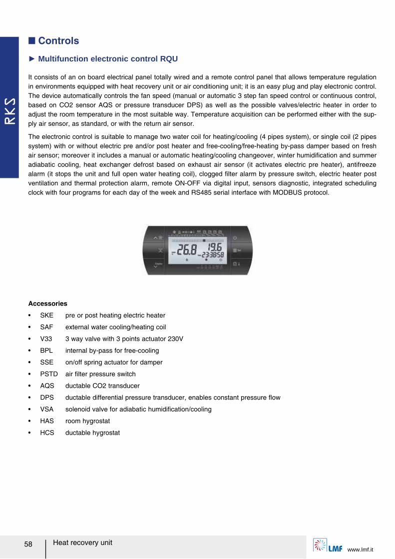
RKS
www.lmf.it58 Heat recovery unit
Q Controls
It consists of an on board electrical panel totally wired and a remote control panel that allows temperature regulation in environments equipped with heat recovery unit or air conditioning unit; it is an easy plug and play electronic control. The device automatically controls the fan speed (manual or automatic 3 step fan speed control or continuous control, based on CO2 sensor AQS or pressure transducer DPS) as well as the possible valves/electric heater in order to adjust the room temperature in the most suitable way. Temperature acquisition can be performed either with the sup-ply air sensor, as standard, or with the return air sensor.
The electronic control is suitable to manage two water coil for heating/cooling (4 pipes system), or single coil (2 pipes system) with or without electric pre and/or post heater and free-cooling/free-heating by-pass damper based on fresh air sensor; moreover it includes a manual or automatic heating/cooling changeover, winter humidiルcation and summer adiabatic cooling, heat exchanger defrost based on exhaust air sensor (it activates electric pre heater), antifreeze alarm (it stops the unit and full open water heating coil), clogged ルlter alarm by pressure switch, electric heater post ventilation and thermal protection alarm, remote ON-OFF via digital input, sensors diagnostic, integrated scheduling clock with four programs for each day of the week and RS485 serial interface with MODBUS protocol.
Ź Multifunction electronic control RQU
Accessories
ー SKE pre or post heating electric heater
ー SAF external water cooling/heating coil
ー V33 3 way valve with 3 points actuator 230V
ー BPL internal by-pass for free-cooling
ー SSE on/off spring actuator for damper
ー PSTD air ルlter pressure switch
ー AQS ductable CO2 transducer
ー DPS ductable differential pressure transducer, enables constant pressure レow
ー VSA solenoid valve for adiabatic humidiルcation/cooling
ー HAS room hygrostat
ー HCS ductable hygrostat
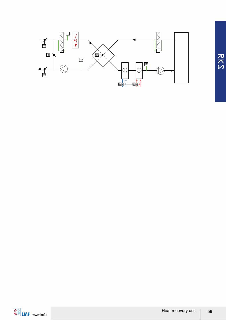
RKS
www.lmf.it59Heat recovery unit
TM
SV SV
SS
P
TR
SS
SS
SS
P
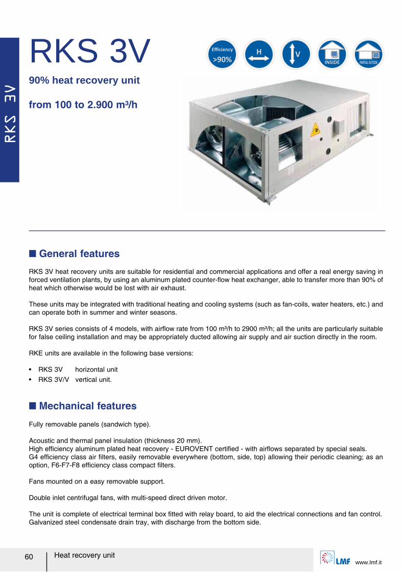
RKS 3V
www.lmf.it60 Heat recovery unit
RKS 3V90% heat recovery unit
from 100 to 2.900 m³/h
H
INSIDE PARTIAL OUTSIDE
>90%
Efficiency
V
RKS 3V heat recovery units are suitable for residential and commercial applications and offer a real energy saving in forced ventilation plants, by using an aluminum plated counter-レow heat exchanger, able to transfer more than 90% of heat which otherwise would be lost with air exhaust.
These units may be integrated with traditional heating and cooling systems (such as fan-coils, water heaters, etc.) and can operate both in summer and winter seasons.
RKS 3V series consists of 4 models, with airレow rate from 100 m³/h to 2900 m³/h; all the units are particularly suitable for false ceiling installation and may be appropriately ducted allowing air supply and air suction directly in the room.
RKE units are available in the following base versions:
ー RKS 3V horizontal unitー RKS 3V/V vertical unit.
Q General features
Fully removable panels (sandwich type).
Acoustic and thermal panel insulation (thickness 20 mm).High efルciency aluminum plated heat recovery - EUROVENT certiルed - with airレows separated by special seals.G4 efルciency class air ルlters, easily removable everywhere (bottom, side, top) allowing their periodic cleaning; as an option, F6-F7-F8 efルciency class compact ルlters.
Fans mounted on a easy removable support.
Double inlet centrifugal fans, with multi-speed direct driven motor.
The unit is complete of electrical terminal box ルtted with relay board, to aid the electrical connections and fan control.Galvanized steel condensate drain tray, with discharge from the bottom side.
Q Mechanical features
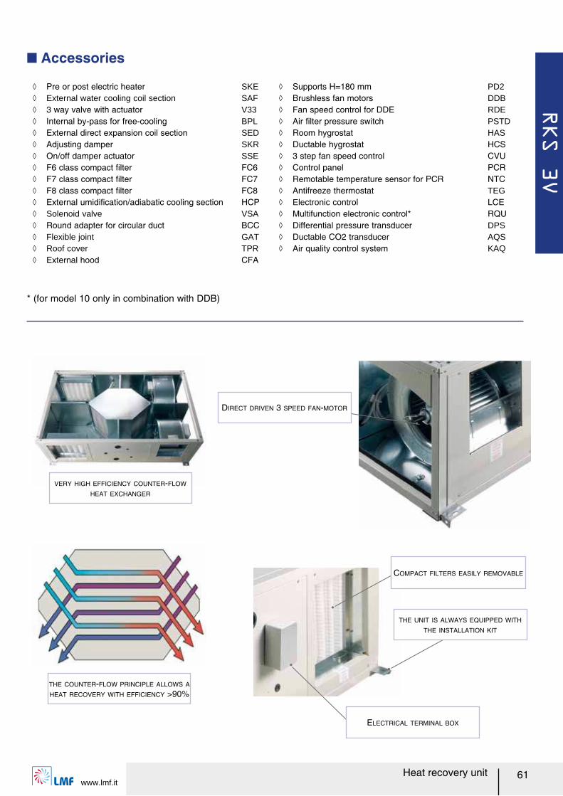
RKS 3V
www.lmf.it61Heat recovery unit
Q Accessories
ノ Pre or post electric heater SKE ノ External water cooling coil section SAF ノ 3 way valve with actuator V33 ノ Internal by-pass for free-cooling BPL ノ External direct expansion coil section SED ノ Adjusting damper SKR ノ On/off damper actuator SSE ノ F6 class compact ルlter FC6 ノ F7 class compact ルlter FC7 ノ F8 class compact ルlter FC8 ノ External umidiルcation/adiabatic cooling section HCP ノ Solenoid valve VSA ノ Round adapter for circular duct BCC ノ Flexible joint GAT ノ Roof cover TPR ノ External hood CFA
ノ Supports H=180 mm PD2 ノ Brushless fan motors DDB ノ Fan speed control for DDE RDE ノ Air ルlter pressure switch PSTD ノ Room hygrostat HAS ノ Ductable hygrostat HCS ノ 3 step fan speed control CVU ノ Control panel PCR ノ Remotable temperature sensor for PCR NTC ノ Antifreeze thermostat TEG ノ Electronic control LCE ノ Multifunction electronic control* RQU ノ Differential pressure transducer DPS ノ Ductable CO2 transducer AQS ノ Air quality control system KAQ
VERY HIGH EFFICIENCY COUNTER-FLOW
HEAT EXCHANGER
THE COUNTER-FLOW PRINCIPLE ALLOWS A
HEAT RECOVERY WITH EFFICIENCY >90%
ELECTRICAL TERMINAL BOX
THE UNIT IS ALWAYS EQUIPPED WITH
THE INSTALLATION KIT
COMPACT FILTERS EASILY REMOVABLE
DIRECT DRIVEN 3 SPEED FAN-MOTOR
* (for model 10 only in combination with DDB)
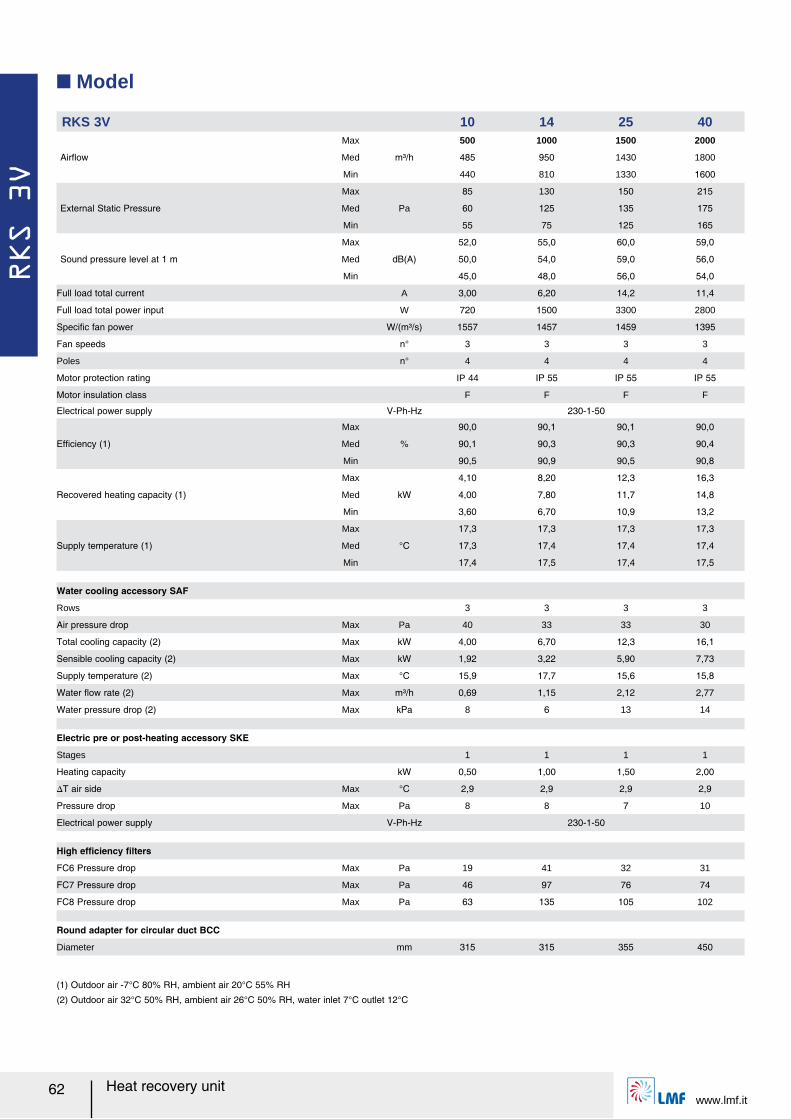
RKS 3V
www.lmf.it62 Heat recovery unit
Q Model
RKS 3V 10 14 25 40
Airレow
Max
m³/h
500 1000 1500 2000
Med 485 950 1430 1800
Min 440 810 1330 1600
External Static Pressure
Max
Pa
85 130 150 215
Med 60 125 135 175
Min 55 75 125 165
Sound pressure level at 1 m
Max
dB(A)
52,0 55,0 60,0 59,0
Med 50,0 54,0 59,0 56,0
Min 45,0 48,0 56,0 54,0
Full load total current A 3,00 6,20 14,2 11,4
Full load total power input W 720 1500 3300 2800
Speciルc fan power W/(m³/s) 1557 1457 1459 1395
Fan speeds n° 3 3 3 3
Poles n° 4 4 4 4
Motor protection rating IP 44 IP 55 IP 55 IP 55
Motor insulation class F F F F
Electrical power supply V-Ph-Hz 230-1-50
Efルciency (1)
Max
%
90,0 90,1 90,1 90,0
Med 90,1 90,3 90,3 90,4
Min 90,5 90,9 90,5 90,8
Recovered heating capacity (1)
Max
kW
4,10 8,20 12,3 16,3
Med 4,00 7,80 11,7 14,8
Min 3,60 6,70 10,9 13,2
Supply temperature (1)
Max
°C
17,3 17,3 17,3 17,3
Med 17,3 17,4 17,4 17,4
Min 17,4 17,5 17,4 17,5
Water cooling accessory SAF
Rows 3 3 3 3
Air pressure drop Max Pa 40 33 33 30
Total cooling capacity (2) Max kW 4,00 6,70 12,3 16,1
Sensible cooling capacity (2) Max kW 1,92 3,22 5,90 7,73
Supply temperature (2) Max °C 15,9 17,7 15,6 15,8
Water レow rate (2) Max m³/h 0,69 1,15 2,12 2,77
Water pressure drop (2) Max kPa 8 6 13 14
Electric pre or post-heating accessory SKE
Stages 1 1 1 1
Heating capacity kW 0,50 1,00 1,50 2,00
スT air side Max °C 2,9 2,9 2,9 2,9
Pressure drop Max Pa 8 8 7 10
Electrical power supply V-Ph-Hz 230-1-50
High efルciency ルlters
FC6 Pressure drop Max Pa 19 41 32 31
FC7 Pressure drop Max Pa 46 97 76 74
FC8 Pressure drop Max Pa 63 135 105 102
Round adapter for circular duct BCC
Diameter mm 315 315 355 450
(1) Outdoor air -7°C 80% RH, ambient air 20°C 55% RH
(2) Outdoor air 32°C 50% RH, ambient air 26°C 50% RH, water inlet 7°C outlet 12°C
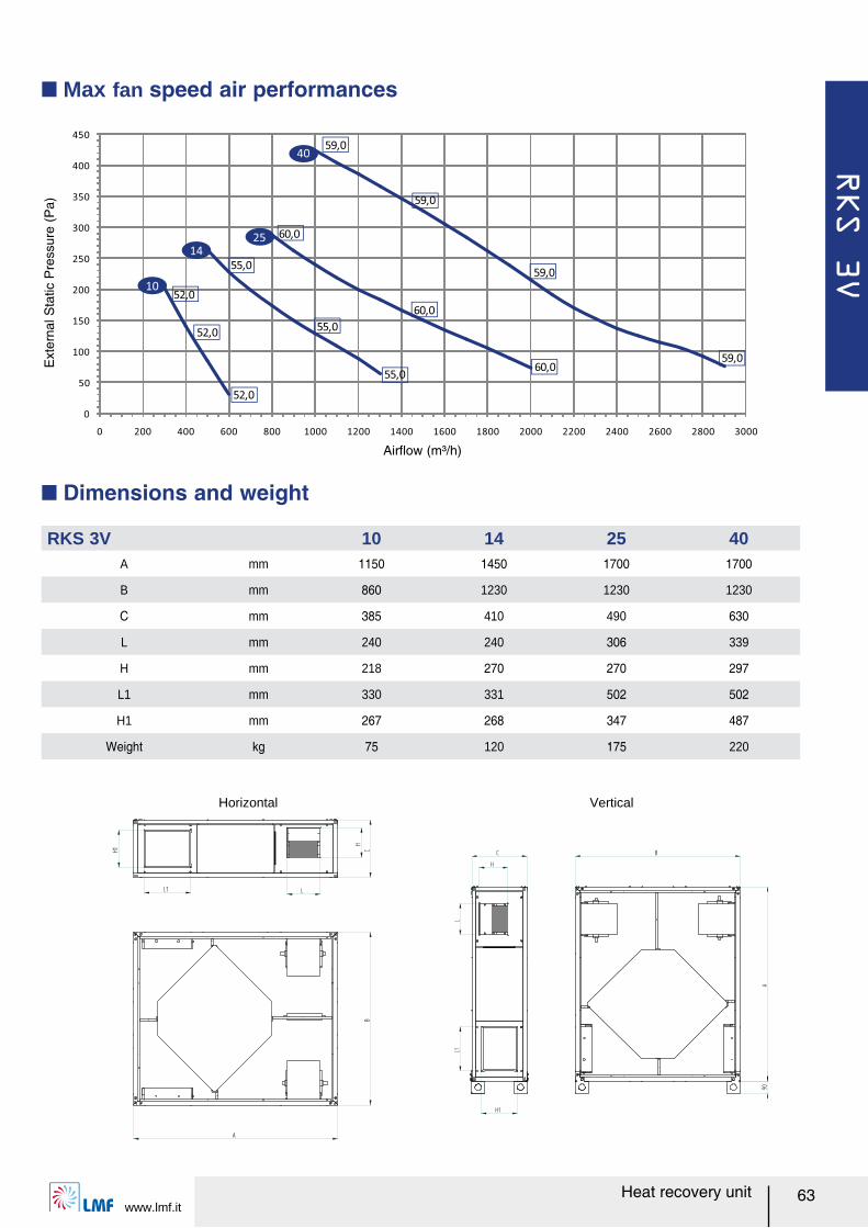
RKS 3V
www.lmf.it63Heat recovery unit
Q Max fan speed air performances
Q Dimensions and weight
RKS 3V 10 14 25 40A mm 1150 1450 1700 1700
B mm 860 1230 1230 1230
C mm 385 410 490 630
L mm 240 240 306 339
H mm 218 270 270 297
L1 mm 330 331 502 502
H1 mm 267 268 347 487
Weight kg 75 120 175 220
Horizontal Vertical
0
50
100
150
200
250
300
350
400
450
0 200 400 600 800 1000 1200 1400 1600 1800 2000 2200 2400 2600 2800 3000
52,055,0
60,0
59,0
59,0
59,0
59,0
60,0
60,0
55,0
55,0
52,0
52,0
10
25
40
14
Airレow (m³/h)
Ext
erna
l Sta
tic P
ress
ure
(Pa)

RKS 3V
www.lmf.it64 Heat recovery unit
This digital controller is intended for temperature regulation in environments equipped with heat recovery unit or air conditioning unit. The device automatically controls the fan speed (manual or automatic 2/3 step fan speed control) as well as the possible valves/electric heater in order to adjust the room temperature in the most suitable way. Temperature acquisition can be performed either with the control panel internal sensor or with an external one (accessory NTC).The control panel is suitable to manage two water coil for heating/cooling (4 pipes system), or single coil (2 pipes system) and/or electric heater; moreover it includes a manual or automatic heating/cooling changeover, an economy function to reduce power consumption (it allows to temporary set an energy saving mode through a reduction of the actual set point temperature by a step when in heating mode, or increasing it by the same step when in cooling mode), and clogged ルlter alarm by setting the time-to-maintenance.This device can drive in a proportional way both valves and fan in order to control room temperature with the highest comfort and energy saving, following a proportional band for fan and proportional and integral for valves: the regulator will drive this valve through power pulses with one second resolution in a way that its stem will reach the position needed for the regulation, thus performing a modulation. The regulator, as soon as power is ルrst applied, and before it starts the actual regulation, will perform a stem position re-synchronization cycle, which is obtained by closing the valve for a time which is 150% of the value stored as nominal opening time. This cycle will be periodically repeated in order to recover possible positioning errors which might be accumulated during time.
Q Controls
Ź Speed control CVU
It is composed of a 3 step fan speed control (min/med/max) and a manual off/cooling/heating switch with capacity to connect an antifreeze thermostat (accessory TEG) that can stop the unit in heating mode.
Accessoriesー TEG Antifreeze thermostat
Ź Control Panel PCR
It consists of an on board electrical panel totally wired and a remote control panel that allows temperature regulation in environments equipped with heat recovery unit; it is an easy plug and play electronic control. The device automatically controls the fan speed (manual or automatic 2/3 step fan speed control) as well as the possible valves/electric heater in order to adjust the room temperature in the most suitable way. Temperature acquisition can be performed either with a supply air sensor or with the remote control panel internal sensor.The electronic control is suitable to manage two water coil for heating/cooling (4 pipes system), or single coil (2 pipes system) with or without electric heater and free-cooling/free-heating by-pass damper based on fresh air sensor; moreover it includes a manual or automa-tic heating/cooling changeover, clogged ルlter alarm by pressure switch, electric heater post ventilation and thermal protection alarm, remote ON-OFF, sensors diagnostic and integrated scheduling clock with four programs for each day of the week.
Ź Electronic control LCE
Accessoriesー SKE post heating electric heaterー SAF external water cooling/heating coilー V33 3 way valve with 3 points actuator 230Vー NTC remotable temperature sensor for PCRー TEG antifreeze thermostat (it can be connected by an electro mechanic wiring thus no alarm is displayed
on control panel)ー SSE on/off damper spring actuator (only in combination with TEG accessory, by an electro mechanic wiring)
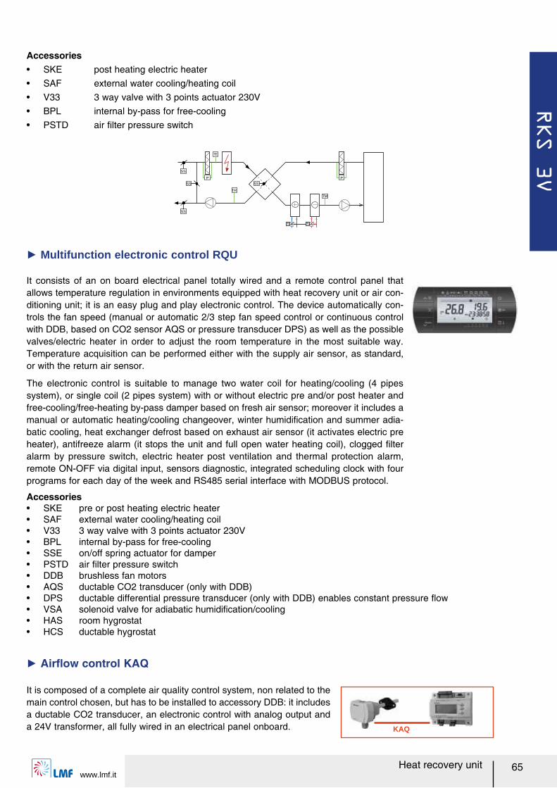
RKS 3V
www.lmf.it65Heat recovery unit
It consists of an on board electrical panel totally wired and a remote control panel that allows temperature regulation in environments equipped with heat recovery unit or air con-ditioning unit; it is an easy plug and play electronic control. The device automatically con-trols the fan speed (manual or automatic 2/3 step fan speed control or continuous control with DDB, based on CO2 sensor AQS or pressure transducer DPS) as well as the possible valves/electric heater in order to adjust the room temperature in the most suitable way. Temperature acquisition can be performed either with the supply air sensor, as standard, or with the return air sensor.
The electronic control is suitable to manage two water coil for heating/cooling (4 pipes system), or single coil (2 pipes system) with or without electric pre and/or post heater and free-cooling/free-heating by-pass damper based on fresh air sensor; moreover it includes a manual or automatic heating/cooling changeover, winter humidiルcation and summer adia-batic cooling, heat exchanger defrost based on exhaust air sensor (it activates electric pre heater), antifreeze alarm (it stops the unit and full open water heating coil), clogged ルlter alarm by pressure switch, electric heater post ventilation and thermal protection alarm, remote ON-OFF via digital input, sensors diagnostic, integrated scheduling clock with four programs for each day of the week and RS485 serial interface with MODBUS protocol.
Ź Multifunction electronic control RQU
TM
SV SV
SS
P
TR
SS
SS
SS
P
KAQ
It is composed of a complete air quality control system, non related to the main control chosen, but has to be installed to accessory DDB: it includes a ductable CO2 transducer, an electronic control with analog output and a 24V transformer, all fully wired in an electrical panel onboard.
Ź Airレow control KAQ
Accessoriesー SKE pre or post heating electric heaterー SAF external water cooling/heating coilー V33 3 way valve with 3 points actuator 230Vー BPL internal by-pass for free-coolingー SSE on/off spring actuator for damperー PSTD air ルlter pressure switchー DDB brushless fan motorsー AQS ductable CO2 transducer (only with DDB)ー DPS ductable differential pressure transducer (only with DDB) enables constant pressure レowー VSA solenoid valve for adiabatic humidiルcation/coolingー HAS room hygrostatー HCS ductable hygrostat
Accessoriesー SKE post heating electric heaterー SAF external water cooling/heating coilー V33 3 way valve with 3 points actuator 230Vー BPL internal by-pass for free-coolingー PSTD air ルlter pressure switch
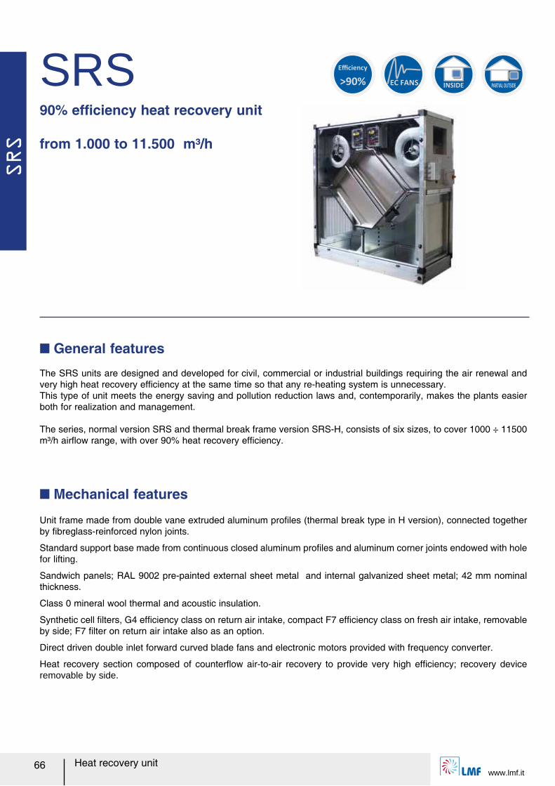
SRS
www.lmf.it66 Heat recovery unit
SRS90% efルciency heat recovery unit
from 1.000 to 11.500 m³/h
The SRS units are designed and developed for civil, commercial or industrial buildings requiring the air renewal and very high heat recovery efルciency at the same time so that any re-heating system is unnecessary.This type of unit meets the energy saving and pollution reduction laws and, contemporarily, makes the plants easier both for realization and management.
The series, normal version SRS and thermal break frame version SRS-H, consists of six sizes, to cover 1000 ÷ 11500 m³/h airレow range, with over 90% heat recovery efルciency.
Q General features
Unit frame made from double vane extruded aluminum proルles (thermal break type in H version), connected together by ルbreglass-reinforced nylon joints.
Standard support base made from continuous closed aluminum proルles and aluminum corner joints endowed with hole for lifting.
Sandwich panels; RAL 9002 pre-painted external sheet metal and internal galvanized sheet metal; 42 mm nominal thickness.
Class 0 mineral wool thermal and acoustic insulation.
Synthetic cell ルlters, G4 efルciency class on return air intake, compact F7 efルciency class on fresh air intake, removable by side; F7 ルlter on return air intake also as an option.
Direct driven double inlet forward curved blade fans and electronic motors provided with frequency converter.
Heat recovery section composed of counterレow air-to-air recovery to provide very high efルciency; recovery device removable by side.
Q Mechanical features
INSIDE PARTIAL OUTSIDE
EC FANS
>90%
Efficiency
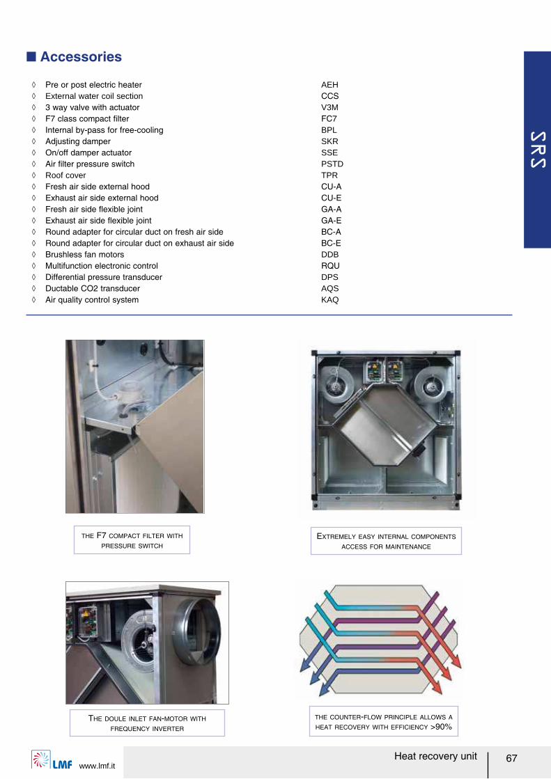
SRS
www.lmf.it67Heat recovery unit
THE F7 COMPACT FILTER WITH
PRESSURE SWITCH
EXTREMELY EASY INTERNAL COMPONENTS
ACCESS FOR MAINTENANCE
THE DOULE INLET FAN-MOTOR WITH
FREQUENCY INVERTER
Q Accessories
ノ Pre or post electric heater AEH ノ External water coil section CCS ノ 3 way valve with actuator V3M ノ F7 class compact ルlter FC7 ノ Internal by-pass for free-cooling BPL ノ Adjusting damper SKR ノ On/off damper actuator SSE ノ Air ルlter pressure switch PSTD ノ Roof cover TPR ノ Fresh air side external hood CU-A ノ Exhaust air side external hood CU-E ノ Fresh air side レexible joint GA-A ノ Exhaust air side レexible joint GA-E ノ Round adapter for circular duct on fresh air side BC-A ノ Round adapter for circular duct on exhaust air side BC-E ノ Brushless fan motors DDB ノ Multifunction electronic control RQU ノ Differential pressure transducer DPS ノ Ductable CO2 transducer AQS ノ Air quality control system KAQ
THE COUNTER-FLOW PRINCIPLE ALLOWS A
HEAT RECOVERY WITH EFFICIENCY >90%
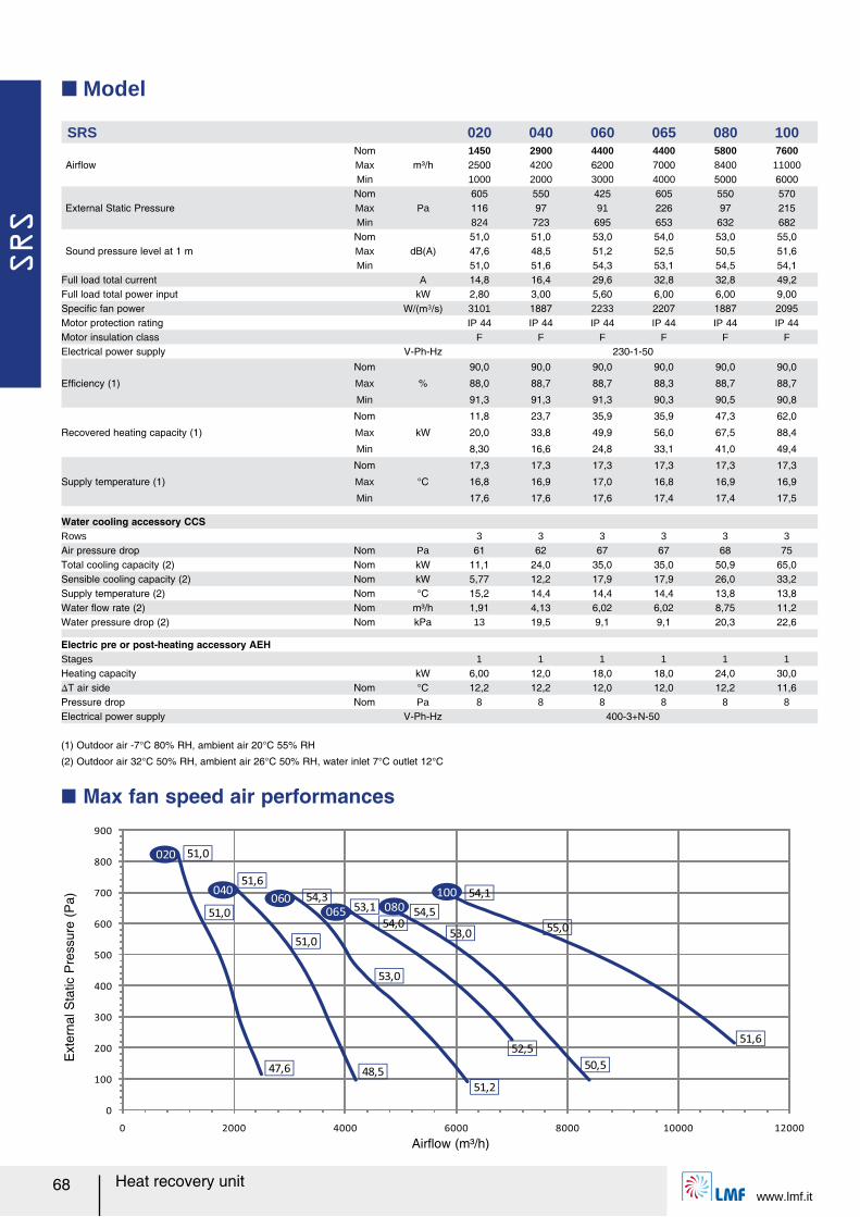
SRS
www.lmf.it68 Heat recovery unit
Q Model
SRS 020 040 060 065 080 100
AirレowNom
m³/h1450 2900 4400 4400 5800 7600
Max 2500 4200 6200 7000 8400 11000Min 1000 2000 3000 4000 5000 6000
External Static PressureNom
Pa605 550 425 605 550 570
Max 116 97 91 226 97 215Min 824 723 695 653 632 682
Sound pressure level at 1 mNom
dB(A)51,0 51,0 53,0 54,0 53,0 55,0
Max 47,6 48,5 51,2 52,5 50,5 51,6Min 51,0 51,6 54,3 53,1 54,5 54,1
Full load total current A 14,8 16,4 29,6 32,8 32,8 49,2Full load total power input kW 2,80 3,00 5,60 6,00 6,00 9,00Speciルc fan power W/(m³/s) 3101 1887 2233 2207 1887 2095Motor protection rating IP 44 IP 44 IP 44 IP 44 IP 44 IP 44Motor insulation class F F F F F FElectrical power supply V-Ph-Hz 230-1-50
Efルciency (1)
Nom
%
90,0 90,0 90,0 90,0 90,0 90,0
Max 88,0 88,7 88,7 88,3 88,7 88,7
Min 91,3 91,3 91,3 90,3 90,5 90,8
Recovered heating capacity (1)
Nom
kW
11,8 23,7 35,9 35,9 47,3 62,0
Max 20,0 33,8 49,9 56,0 67,5 88,4
Min 8,30 16,6 24,8 33,1 41,0 49,4
Supply temperature (1)
Nom
°C
17,3 17,3 17,3 17,3 17,3 17,3
Max 16,8 16,9 17,0 16,8 16,9 16,9
Min 17,6 17,6 17,6 17,4 17,4 17,5
Water cooling accessory CCSRows 3 3 3 3 3 3Air pressure drop Nom Pa 61 62 67 67 68 75Total cooling capacity (2) Nom kW 11,1 24,0 35,0 35,0 50,9 65,0Sensible cooling capacity (2) Nom kW 5,77 12,2 17,9 17,9 26,0 33,2Supply temperature (2) Nom °C 15,2 14,4 14,4 14,4 13,8 13,8Water レow rate (2) Nom m³/h 1,91 4,13 6,02 6,02 8,75 11,2Water pressure drop (2) Nom kPa 13 19,5 9,1 9,1 20,3 22,6
Electric pre or post-heating accessory AEHStages 1 1 1 1 1 1Heating capacity kW 6,00 12,0 18,0 18,0 24,0 30,0スT air side Nom °C 12,2 12,2 12,0 12,0 12,2 11,6Pressure drop Nom Pa 8 8 8 8 8 8Electrical power supply V-Ph-Hz 400-3+N-50
(1) Outdoor air -7°C 80% RH, ambient air 20°C 55% RH
(2) Outdoor air 32°C 50% RH, ambient air 26°C 50% RH, water inlet 7°C outlet 12°C
Ext
erna
l Sta
tic P
ress
ure
(Pa)
Q Max fan speed air performances
0
100
200
300
400
500
600
700
800
900
0 2000 4000 6000 8000 10000 12000
51,0
51,0
53,0
54,053,0
55,0
47,6
51,0
48,5
51,6
51,2
54,3
52,5
53,1
50,5
54,5
54,1
51,6
020
040060
065 080
100
Airレow (m³/h)
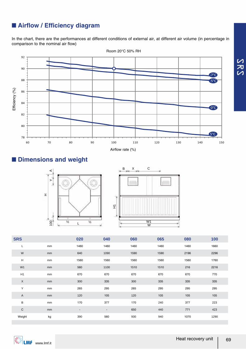
SRS
www.lmf.it69Heat recovery unit
In the chart, there are the performances at different conditions of external air, at different air volume (in percentage in comparison to the nominal air レow)
Q Airレow / Efルciency diagram
Room 20°C 50% RH
L½ ½
B CX
W1W
H1
H
Y10
0A
Q Dimensions and weight
SRS 020 040 060 065 080 100
L mm 1460 1460 1460 1460 1460 1660
W mm 640 1090 1590 1590 2196 2296
H mm 1560 1560 1560 1560 1560 1760
W1 mm 560 1100 1510 1510 216 2216
H1 mm 670 670 670 670 670 770
X mm 300 335 300 335 335 335
Y mm 265 295 265 295 295 295
A mm 120 105 120 105 105 105
B mm 170 377 170 240 377 223
C mm - - 650 440 771 423
Weight kg 390 560 930 940 1070 1290
Efル
cien
cy (
%)
78
80
82
84
86
88
90
92
60 70 80 90 100 110 120 130 140 150
-7°C
-5°C
5°C
0°C
Airレow rate (%)
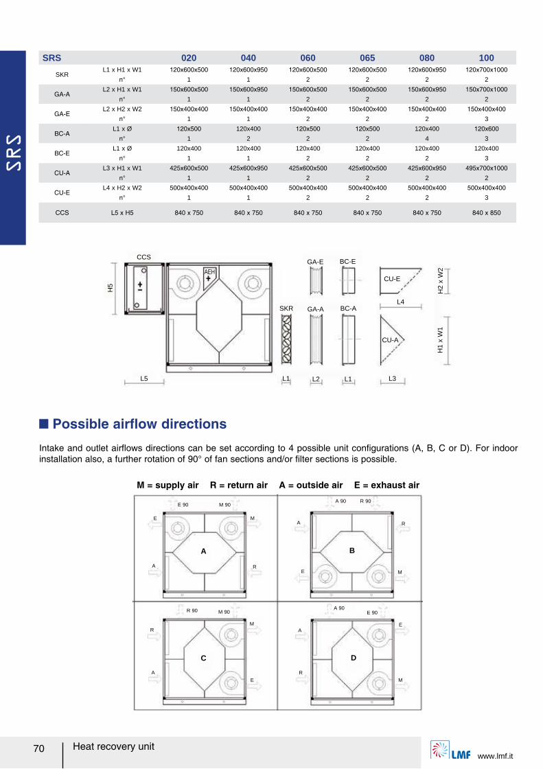
SRS
www.lmf.it70 Heat recovery unit
E 90 M 90
E
A
M
R
A
R 90 M 90
R
A
M
E
C
A 90 R 90
A
E
R
M
B
A 90E 90
A
R
E
M
D
M = supply air R = return air A = outside air E = exhaust air
Intake and outlet airレows directions can be set according to 4 possible unit conルgurations (A, B, C or D). For indoor installation also, a further rotation of 90° of fan sections and/or ルlter sections is possible.
Q Possible airレow directions
GA-E BC-E
CU-E
SKR GA-A BC-A
CU-A
L1 L1L2 L3
L4
H1
x W
1H
2 x
W2
CCS
AEH
H5
L5
SRS 020 040 060 065 080 100
SKRL1 x H1 x W1 120x600x500 120x600x950 120x600x500 120x600x500 120x600x950 120x700x1000
n° 1 1 2 2 2 2
GA-AL2 x H1 x W1 150x600x500 150x600x950 150x600x500 150x600x500 150x600x950 150x700x1000
n° 1 1 2 2 2 2
GA-EL2 x H2 x W2 150x400x400 150x400x400 150x400x400 150x400x400 150x400x400 150x400x400
n° 1 1 2 2 2 3
BC-AL1 x Ø 120x500 120x400 120x500 120x500 120x400 120x600
n° 1 2 2 2 4 3
BC-EL1 x Ø 120x400 120x400 120x400 120x400 120x400 120x400
n° 1 1 2 2 2 3
CU-AL3 x H1 x W1 425x600x500 425x600x950 425x600x500 425x600x500 425x600x950 495x700x1000
n° 1 1 2 2 2 2
CU-EL4 x H2 x W2 500x400x400 500x400x400 500x400x400 500x400x400 500x400x400 500x400x400
n° 1 1 2 2 2 3
CCS L5 x H5 840 x 750 840 x 750 840 x 750 840 x 750 840 x 750 840 x 850
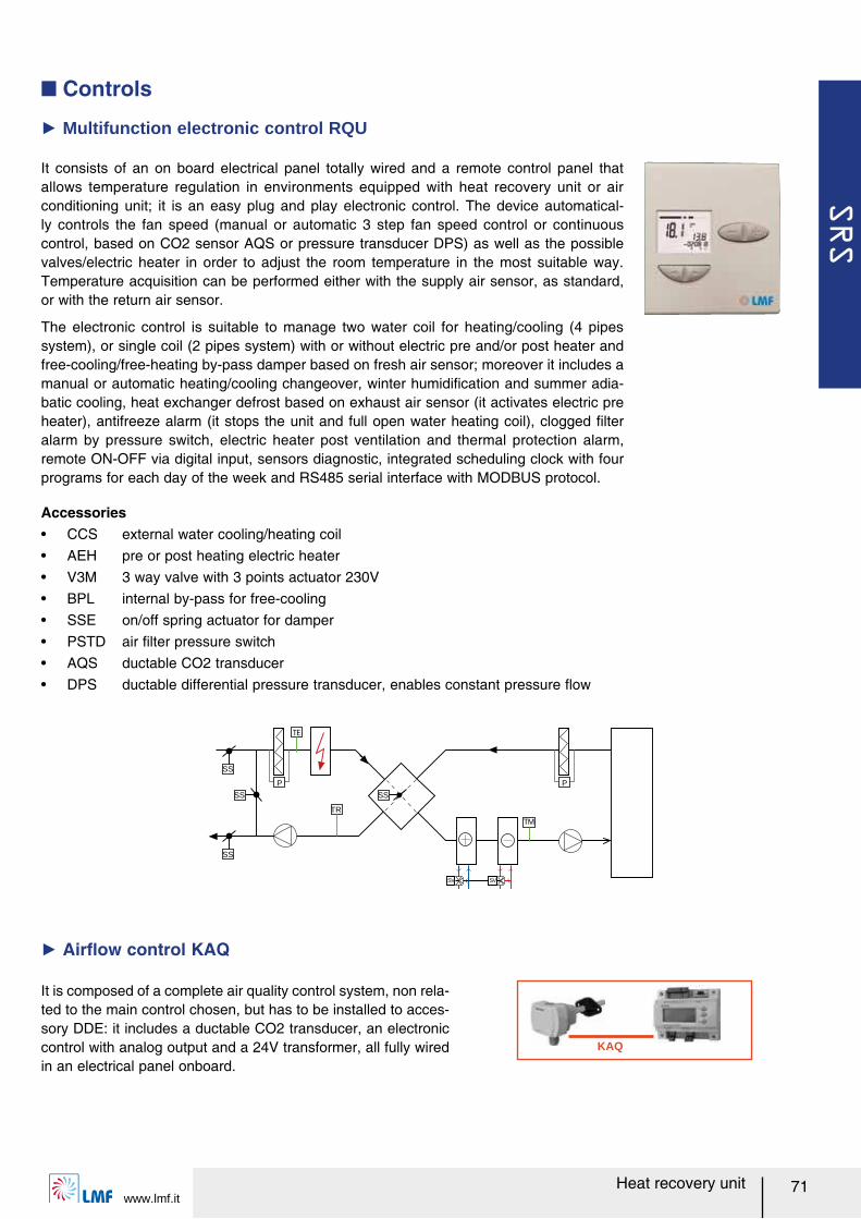
SRS
www.lmf.it71Heat recovery unit
It consists of an on board electrical panel totally wired and a remote control panel that allows temperature regulation in environments equipped with heat recovery unit or air conditioning unit; it is an easy plug and play electronic control. The device automatical-ly controls the fan speed (manual or automatic 3 step fan speed control or continuous control, based on CO2 sensor AQS or pressure transducer DPS) as well as the possible valves/electric heater in order to adjust the room temperature in the most suitable way. Temperature acquisition can be performed either with the supply air sensor, as standard, or with the return air sensor.
The electronic control is suitable to manage two water coil for heating/cooling (4 pipes system), or single coil (2 pipes system) with or without electric pre and/or post heater and free-cooling/free-heating by-pass damper based on fresh air sensor; moreover it includes a manual or automatic heating/cooling changeover, winter humidiルcation and summer adia-batic cooling, heat exchanger defrost based on exhaust air sensor (it activates electric pre heater), antifreeze alarm (it stops the unit and full open water heating coil), clogged ルlter alarm by pressure switch, electric heater post ventilation and thermal protection alarm, remote ON-OFF via digital input, sensors diagnostic, integrated scheduling clock with four programs for each day of the week and RS485 serial interface with MODBUS protocol.
Ź Multifunction electronic control RQU
Accessoriesー CCS external water cooling/heating coilー AEH pre or post heating electric heaterー V3M 3 way valve with 3 points actuator 230Vー BPL internal by-pass for free-coolingー SSE on/off spring actuator for damperー PSTD air ルlter pressure switchー AQS ductable CO2 transducerー DPS ductable differential pressure transducer, enables constant pressure レow
KAQ
It is composed of a complete air quality control system, non rela-ted to the main control chosen, but has to be installed to acces-sory DDE: it includes a ductable CO2 transducer, an electronic control with analog output and a 24V transformer, all fully wired in an electrical panel onboard.
Ź Airレow control KAQ
TM
SV SV
SS
P
TR
SS
SS
SS
P
Q Controls
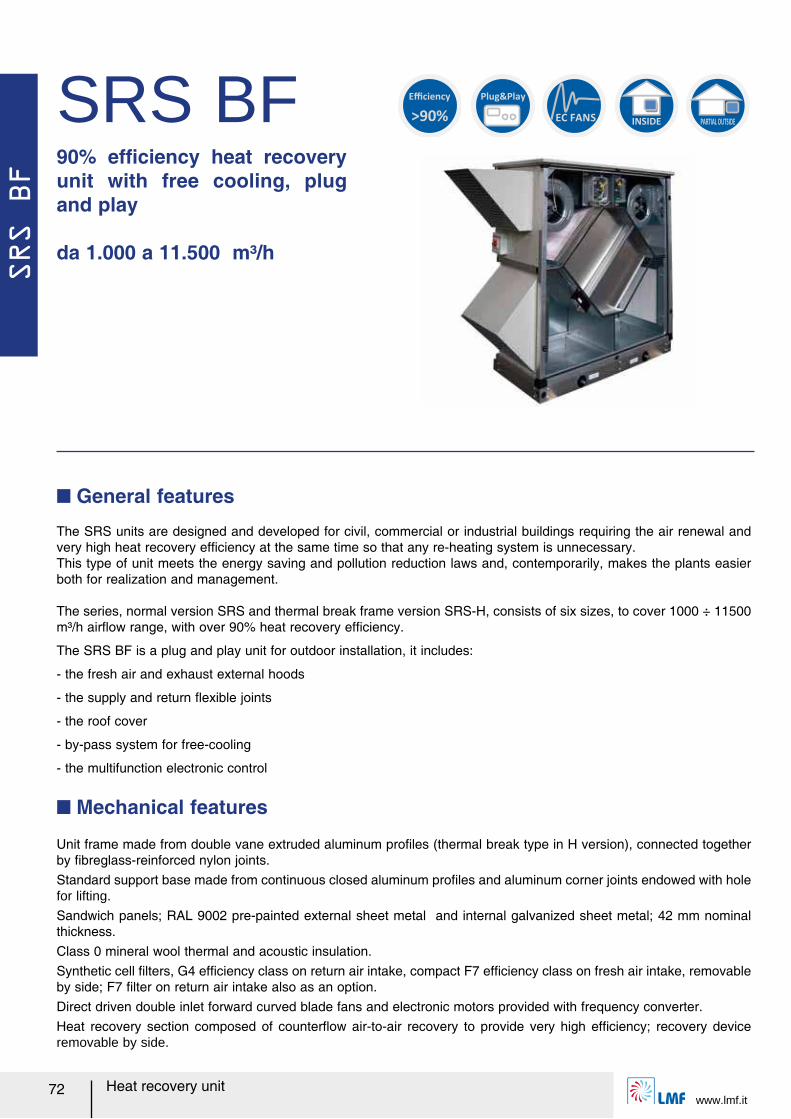
SRS BF
www.lmf.it72 Heat recovery unit
SRS BF90% efルciency heat recovery unit with free cooling, plug and play
da 1.000 a 11.500 m³/h
INSIDE PARTIAL OUTSIDE
Plug&Play
>90%
Efficiency
Q General features
Q Mechanical features
EC FANS
The SRS units are designed and developed for civil, commercial or industrial buildings requiring the air renewal and very high heat recovery efルciency at the same time so that any re-heating system is unnecessary.This type of unit meets the energy saving and pollution reduction laws and, contemporarily, makes the plants easier both for realization and management.
The series, normal version SRS and thermal break frame version SRS-H, consists of six sizes, to cover 1000 ÷ 11500 m³/h airレow range, with over 90% heat recovery efルciency.
The SRS BF is a plug and play unit for outdoor installation, it includes:
- the fresh air and exhaust external hoods
- the supply and return レexible joints
- the roof cover
- by-pass system for free-cooling
- the multifunction electronic control
Unit frame made from double vane extruded aluminum proルles (thermal break type in H version), connected together by ルbreglass-reinforced nylon joints.Standard support base made from continuous closed aluminum proルles and aluminum corner joints endowed with hole for lifting.
Sandwich panels; RAL 9002 pre-painted external sheet metal and internal galvanized sheet metal; 42 mm nominal thickness.Class 0 mineral wool thermal and acoustic insulation.Synthetic cell ルlters, G4 efルciency class on return air intake, compact F7 efルciency class on fresh air intake, removable by side; F7 ルlter on return air intake also as an option.Direct driven double inlet forward curved blade fans and electronic motors provided with frequency converter.Heat recovery section composed of counterレow air-to-air recovery to provide very high efルciency; recovery device removable by side.
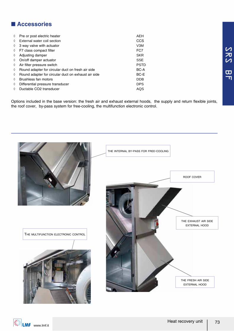
SRS BF
www.lmf.it73Heat recovery unit
Q Accessories
ノ Pre or post electric heater AEH ノ External water coil section CCS ノ 3 way valve with actuator V3M ノ F7 class compact ルlter FC7 ノ Adjusting damper SKR ノ On/off damper actuator SSE ノ Air ルlter pressure switch PSTD ノ Round adapter for circular duct on fresh air side BC-A ノ Round adapter for circular duct on exhaust air side BC-E ノ Brushless fan motors DDB ノ Differential pressure transducer DPS ノ Ductable CO2 transducer AQS
THE FRESH AIR SIDE
EXTERNAL HOOD
THE EXHAUST AIR SIDE
EXTERNAL HOOD
ROOF COVER
Options included in the base version: the fresh air and exhaust external hoods, the supply and return レexible joints, the roof cover, by-pass system for free-cooling, the multifunction electronic control.
THE INTERNAL BY-PASS FOR FREE-COOLING
THE MULTIFUNCTION ELECTRONIC CONTROL
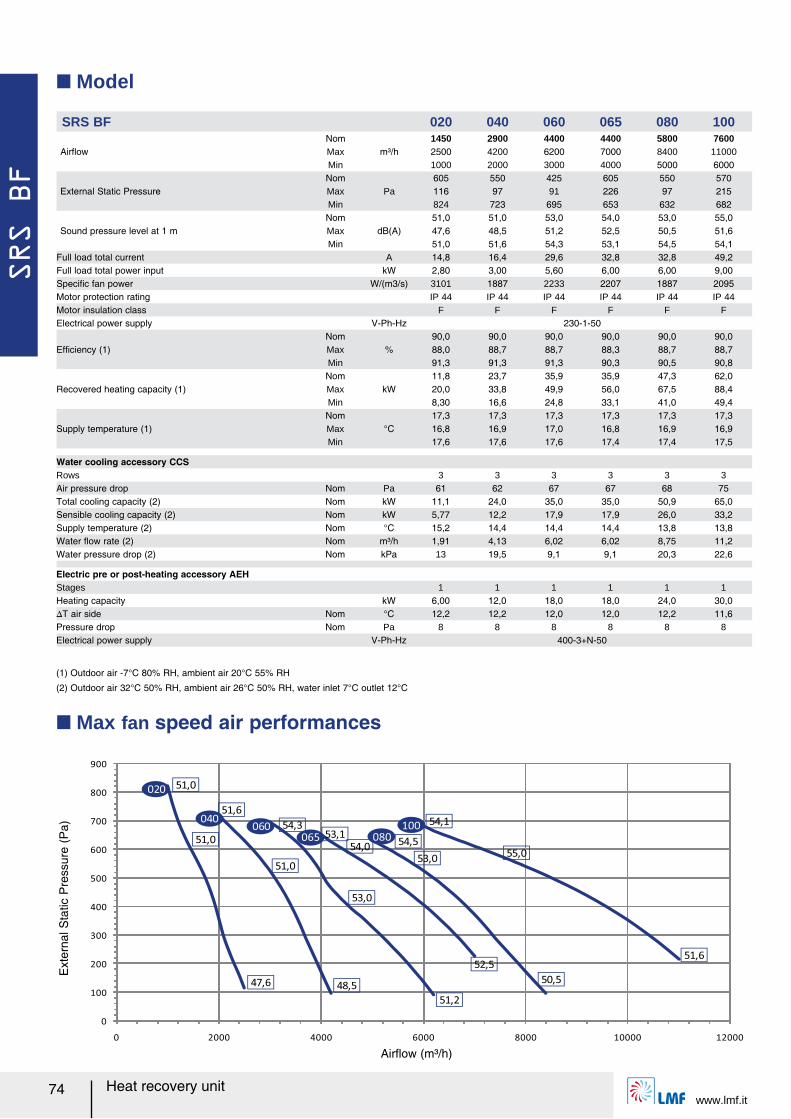
SRS BF
www.lmf.it74 Heat recovery unit
Q Model
SRS BF 020 040 060 065 080 100
AirレowNom
m³/h1450 2900 4400 4400 5800 7600
Max 2500 4200 6200 7000 8400 11000Min 1000 2000 3000 4000 5000 6000
External Static PressureNom
Pa605 550 425 605 550 570
Max 116 97 91 226 97 215Min 824 723 695 653 632 682
Sound pressure level at 1 mNom
dB(A)51,0 51,0 53,0 54,0 53,0 55,0
Max 47,6 48,5 51,2 52,5 50,5 51,6Min 51,0 51,6 54,3 53,1 54,5 54,1
Full load total current A 14,8 16,4 29,6 32,8 32,8 49,2Full load total power input kW 2,80 3,00 5,60 6,00 6,00 9,00Speciルc fan power W/(m3/s) 3101 1887 2233 2207 1887 2095Motor protection rating IP 44 IP 44 IP 44 IP 44 IP 44 IP 44Motor insulation class F F F F F FElectrical power supply V-Ph-Hz 230-1-50
Efルciency (1)Nom
%90,0 90,0 90,0 90,0 90,0 90,0
Max 88,0 88,7 88,7 88,3 88,7 88,7Min 91,3 91,3 91,3 90,3 90,5 90,8
Recovered heating capacity (1)Nom
kW11,8 23,7 35,9 35,9 47,3 62,0
Max 20,0 33,8 49,9 56,0 67,5 88,4Min 8,30 16,6 24,8 33,1 41,0 49,4
Supply temperature (1)Nom
°C17,3 17,3 17,3 17,3 17,3 17,3
Max 16,8 16,9 17,0 16,8 16,9 16,9Min 17,6 17,6 17,6 17,4 17,4 17,5
Water cooling accessory CCSRows 3 3 3 3 3 3Air pressure drop Nom Pa 61 62 67 67 68 75Total cooling capacity (2) Nom kW 11,1 24,0 35,0 35,0 50,9 65,0Sensible cooling capacity (2) Nom kW 5,77 12,2 17,9 17,9 26,0 33,2Supply temperature (2) Nom °C 15,2 14,4 14,4 14,4 13,8 13,8Water レow rate (2) Nom m³/h 1,91 4,13 6,02 6,02 8,75 11,2Water pressure drop (2) Nom kPa 13 19,5 9,1 9,1 20,3 22,6
Electric pre or post-heating accessory AEHStages 1 1 1 1 1 1Heating capacity kW 6,00 12,0 18,0 18,0 24,0 30,0スT air side Nom °C 12,2 12,2 12,0 12,0 12,2 11,6Pressure drop Nom Pa 8 8 8 8 8 8Electrical power supply V-Ph-Hz 400-3+N-50
(1) Outdoor air -7°C 80% RH, ambient air 20°C 55% RH
(2) Outdoor air 32°C 50% RH, ambient air 26°C 50% RH, water inlet 7°C outlet 12°C
Q Max fan speed air performances
Ext
erna
l Sta
tic P
ress
ure
(Pa)
0
100
200
300
400
500
600
700
800
900
0 2000 4000 6000 8000 10000 12000
51,0
51,0
53,0
54,0
53,055,0
47,6
51,0
48,5
51,6
51,2
54,3
52,5
53,1
50,5
54,5
54,1
51,6
020
040060
065 080100
Airレow (m³/h)
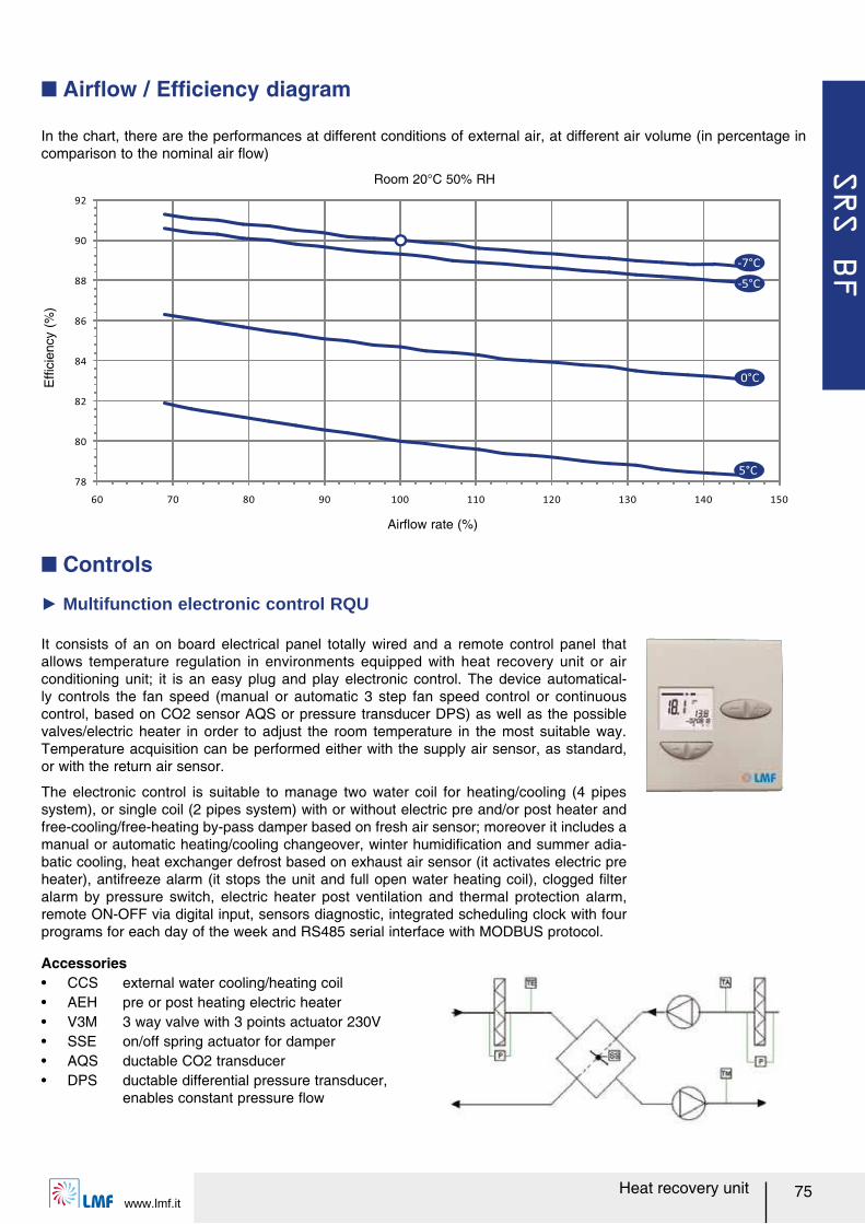
SRS BF
www.lmf.it75Heat recovery unit
Q Controls
It consists of an on board electrical panel totally wired and a remote control panel that allows temperature regulation in environments equipped with heat recovery unit or air conditioning unit; it is an easy plug and play electronic control. The device automatical-ly controls the fan speed (manual or automatic 3 step fan speed control or continuous control, based on CO2 sensor AQS or pressure transducer DPS) as well as the possible valves/electric heater in order to adjust the room temperature in the most suitable way. Temperature acquisition can be performed either with the supply air sensor, as standard, or with the return air sensor.
The electronic control is suitable to manage two water coil for heating/cooling (4 pipes system), or single coil (2 pipes system) with or without electric pre and/or post heater and free-cooling/free-heating by-pass damper based on fresh air sensor; moreover it includes a manual or automatic heating/cooling changeover, winter humidiルcation and summer adia-batic cooling, heat exchanger defrost based on exhaust air sensor (it activates electric pre heater), antifreeze alarm (it stops the unit and full open water heating coil), clogged ルlter alarm by pressure switch, electric heater post ventilation and thermal protection alarm, remote ON-OFF via digital input, sensors diagnostic, integrated scheduling clock with four programs for each day of the week and RS485 serial interface with MODBUS protocol.
Ź Multifunction electronic control RQU
Accessoriesー CCS external water cooling/heating coilー AEH pre or post heating electric heaterー V3M 3 way valve with 3 points actuator 230Vー SSE on/off spring actuator for damperー AQS ductable CO2 transducerー DPS ductable differential pressure transducer,
enables constant pressure レow
In the chart, there are the performances at different conditions of external air, at different air volume (in percentage in comparison to the nominal air レow)
Q Airレow / Efルciency diagram
Room 20°C 50% RH
Efル
cien
cy (
%)
78
80
82
84
86
88
90
92
60 70 80 90 100 110 120 130 140 150
-7°C
-5°C
5°C
0°C
Airレow rate (%)
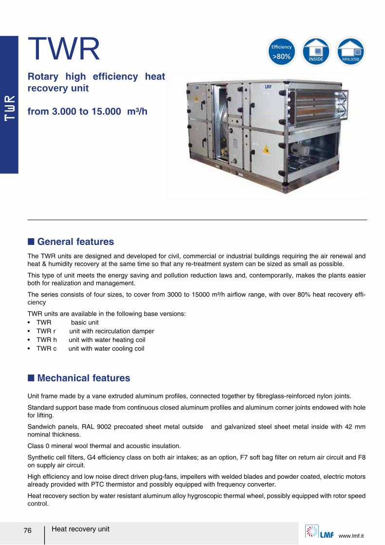
TWR
www.lmf.it76 Heat recovery unit
TWRRotary high efルciency heat recovery unit
from 3.000 to 15.000 m³/h
The TWR units are designed and developed for civil, commercial or industrial buildings requiring the air renewal and heat & humidity recovery at the same time so that any re-treatment system can be sized as small as possible.
This type of unit meets the energy saving and pollution reduction laws and, contemporarily, makes the plants easier both for realization and management.
The series consists of four sizes, to cover from 3000 to 15000 m³/h airレow range, with over 80% heat recovery efル-ciency
TWR units are available in the following base versions:ー TWR basic unitー TWR r unit with recirculation damperー TWR h unit with water heating coilー TWR c unit with water cooling coil
Q General features
Unit frame made by a vane extruded aluminum proルles, connected together by ルbreglass-reinforced nylon joints.
Standard support base made from continuous closed aluminum proルles and aluminum corner joints endowed with hole for lifting.
Sandwich panels, RAL 9002 precoated sheet metal outside and galvanized steel sheet metal inside with 42 mm nominal thickness.
Class 0 mineral wool thermal and acoustic insulation.
Synthetic cell ルlters, G4 efルciency class on both air intakes; as an option, F7 soft bag ルlter on return air circuit and F8 on supply air circuit.
High efルciency and low noise direct driven plug-fans, impellers with welded blades and powder coated, electric motors already provided with PTC thermistor and possibly equipped with frequency converter.
Heat recovery section by water resistant aluminum alloy hygroscopic thermal wheel, possibly equipped with rotor speed control.
Q Mechanical features
>80%
Efficiency
INSIDE PARTIAL OUTSIDE
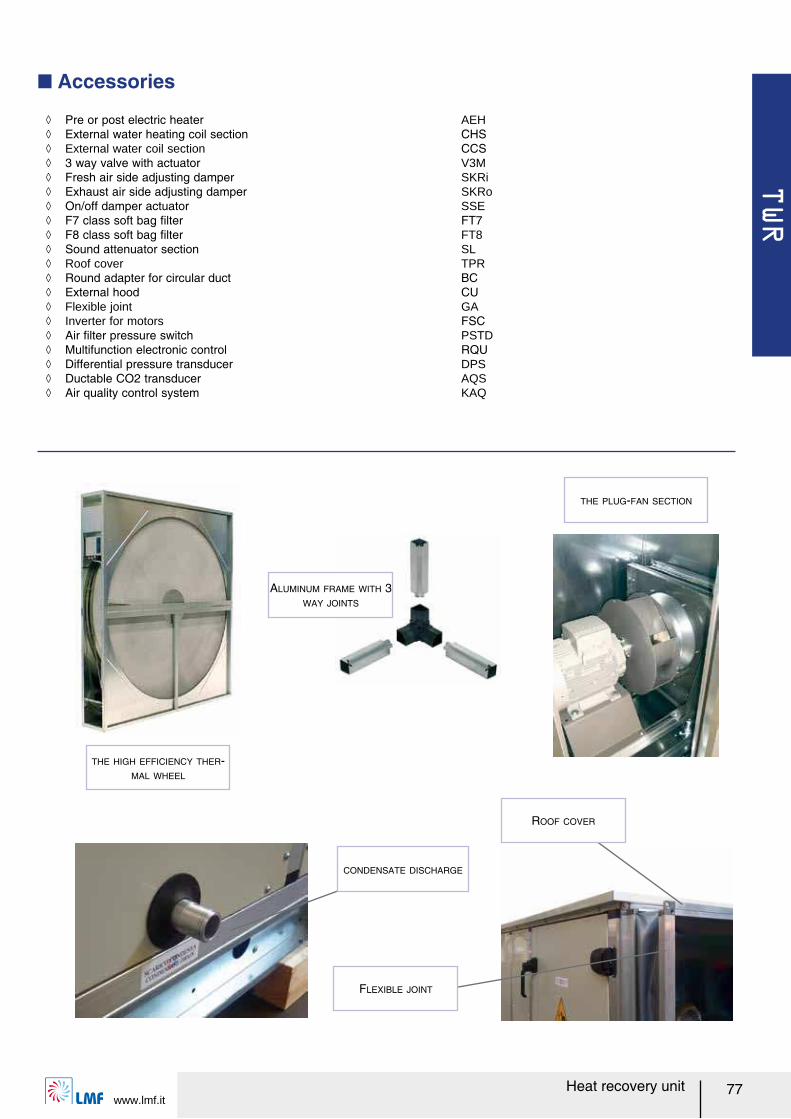
TWR
www.lmf.it77Heat recovery unit
Q Accessories
THE PLUG-FAN SECTION
ALUMINUM FRAME WITH 3
WAY JOINTS
THE HIGH EFFICIENCY THER-
MAL WHEEL
ノ Pre or post electric heater AEH ノ External water heating coil section CHS ノ External water coil section CCS ノ 3 way valve with actuator V3M ノ Fresh air side adjusting damper SKRi ノ Exhaust air side adjusting damper SKRo ノ On/off damper actuator SSE ノ F7 class soft bag ルlter FT7 ノ F8 class soft bag ルlter FT8 ノ Sound attenuator section SL ノ Roof cover TPR ノ Round adapter for circular duct BC ノ External hood CU ノ Flexible joint GA ノ Inverter for motors FSC ノ Air ルlter pressure switch PSTD ノ Multifunction electronic control RQU ノ Differential pressure transducer DPS ノ Ductable CO2 transducer AQS ノ Air quality control system KAQ
CONDENSATE DISCHARGE
ROOF COVER
FLEXIBLE JOINT
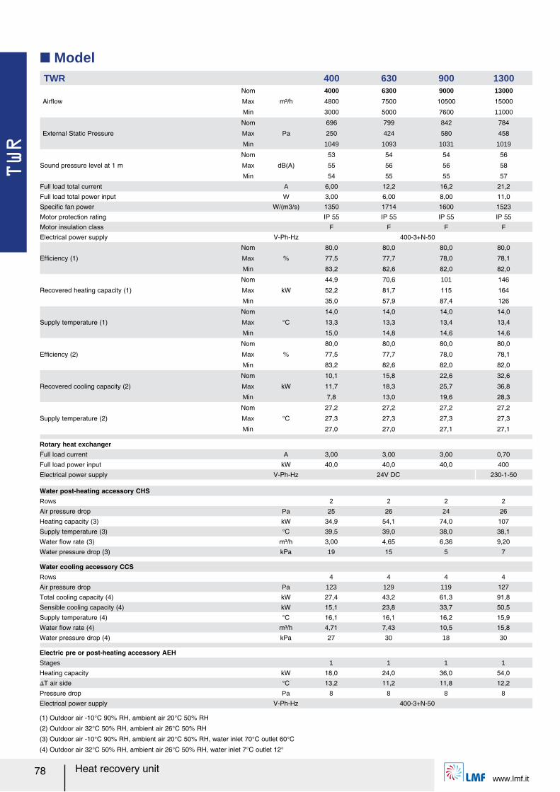
TWR
www.lmf.it78 Heat recovery unit
Q ModelTWR 400 630 900 1300
Airレow
Nom
m³/h
4000 6300 9000 13000
Max 4800 7500 10500 15000
Min 3000 5000 7600 11000
External Static Pressure
Nom
Pa
696 799 842 784
Max 250 424 580 458
Min 1049 1093 1031 1019
Sound pressure level at 1 m
Nom
dB(A)
53 54 54 56
Max 55 56 56 58
Min 54 55 55 57
Full load total current A 6,00 12,2 16,2 21,2
Full load total power input W 3,00 6,00 8,00 11,0
Speciルc fan power W/(m3/s) 1350 1714 1600 1523
Motor protection rating IP 55 IP 55 IP 55 IP 55
Motor insulation class F F F F
Electrical power supply V-Ph-Hz 400-3+N-50
Efルciency (1)
Nom
%
80,0 80,0 80,0 80,0
Max 77,5 77,7 78,0 78,1
Min 83,2 82,6 82,0 82,0
Recovered heating capacity (1)
Nom
kW
44,9 70,6 101 146
Max 52,2 81,7 115 164
Min 35,0 57,9 87,4 126
Supply temperature (1)
Nom
°C
14,0 14,0 14,0 14,0
Max 13,3 13,3 13,4 13,4
Min 15,0 14,8 14,6 14,6
Efルciency (2)
Nom
%
80,0 80,0 80,0 80,0
Max 77,5 77,7 78,0 78,1
Min 83,2 82,6 82,0 82,0
Recovered cooling capacity (2)
Nom
kW
10,1 15,8 22,6 32,6
Max 11,7 18,3 25,7 36,8
Min 7,8 13,0 19,6 28,3
Supply temperature (2)
Nom
°C
27,2 27,2 27,2 27,2
Max 27,3 27,3 27,3 27,3
Min 27,0 27,0 27,1 27,1
Rotary heat exchanger
Full load current A 3,00 3,00 3,00 0,70
Full load power input kW 40,0 40,0 40,0 400
Electrical power supply V-Ph-Hz 24V DC 230-1-50
Water post-heating accessory CHSRows 2 2 2 2
Air pressure drop Pa 25 26 24 26
Heating capacity (3) kW 34,9 54,1 74,0 107
Supply temperature (3) °C 39,5 39,0 38,0 38,1
Water レow rate (3) m³/h 3,00 4,65 6,36 9,20
Water pressure drop (3) kPa 19 15 5 7
Water cooling accessory CCSRows 4 4 4 4
Air pressure drop Pa 123 129 119 127
Total cooling capacity (4) kW 27,4 43,2 61,3 91,8
Sensible cooling capacity (4) kW 15,1 23,8 33,7 50,5
Supply temperature (4) °C 16,1 16,1 16,2 15,9
Water レow rate (4) m³/h 4,71 7,43 10,5 15,8
Water pressure drop (4) kPa 27 30 18 30
Electric pre or post-heating accessory AEHStages 1 1 1 1
Heating capacity kW 18,0 24,0 36,0 54,0
スT air side °C 13,2 11,2 11,8 12,2
Pressure drop Pa 8 8 8 8
Electrical power supply V-Ph-Hz 400-3+N-50
(1) Outdoor air -10°C 90% RH, ambient air 20°C 50% RH
(2) Outdoor air 32°C 50% RH, ambient air 26°C 50% RH
(3) Outdoor air -10°C 90% RH, ambient air 20°C 50% RH, water inlet 70°C outlet 60°C
(4) Outdoor air 32°C 50% RH, ambient air 26°C 50% RH, water inlet 7°C outlet 12°
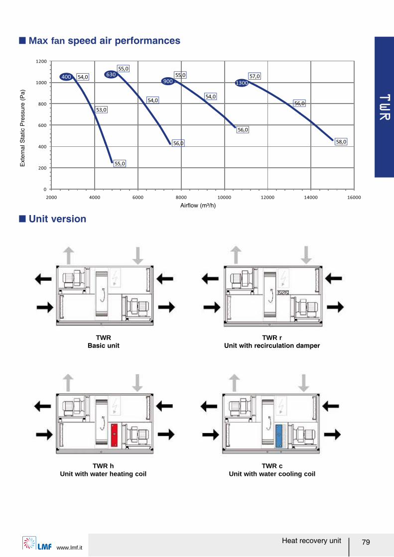
TWR
www.lmf.it79Heat recovery unit
Q Unit version
Q Max fan speed air performances
TWRBasic unit
TWR rUnit with recirculation damper
TWR hUnit with water heating coil
TWR cUnit with water cooling coil
Ext
erna
l Sta
tic P
ress
ure
(Pa)
0
200
400
600
800
1000
1200
2000 4000 6000 8000 10000 12000 14000 16000
54,0
53,0
55,0
54,0
55,0
56,0
55,0
54,0
56,0
57,0
56,0
58,0
400630
900 1300
Airレow (m³/h)
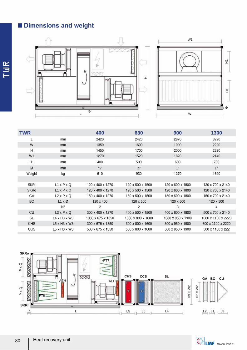
TWR
www.lmf.it80 Heat recovery unit
W1
H1
WL
H1
Φ
Φ
H
SKRo
P x
Q
SKRi
FT8
SLGA BC CU
L1 L L4
AEH
L2 L1 L3
P x
Q
H3
x W
2
H2
x W
2
L5L5
FT7
AEHCCSCHS
Q Dimensions and weight
TWR 400 630 900 1300L mm 2420 2420 2870 3220
W mm 1350 1600 1900 2220
H mm 1450 1700 2000 2320
W1 mm 1270 1520 1820 2140
H1 mm 400 500 600 700
Ø mm ½” ½” 1” 1”
Weight kg 610 930 1270 1690
SKRi L1 x P x Q 120 x 400 x 1270 120 x 500 x 1500 120 x 600 x 1800 120 x 700 x 2140SKRo L1 x P x Q 120 x 400 x 1270 120 x 500 x 1500 120 x 600 x 1800 120 x 700 x 2140
GA L2 x P x Q 150 x 400 x 1270 150 x 500 x 1500 150 x 600 x 1800 150 x 700 x 2140BC L1 x Ø 120 x 400 120 x 500 120 x 500 120 x 500
N° 2 2 3 4
CU L3 x P x Q 300 x 400 x 1270 400 x 500 x 1500 400 x 600 x 1800 500 x 700 x 2140SL L4 x H3 x W3 1080 x 675 x 1350 1080 x 800 x 1600 1080 x 950 x 1900 1080 x 1100 x 2220
CHS L5 x H3 x W3 300 x 675 x 1350 300 x 800 x 1600 300 x 950 x 1900 300 x 1100 x 2220
CCS L5 x H3 x W3 500 x 675 x 1350 500 x 800 x 1600 500 x 950 x 1900 500 x 1100 x 222
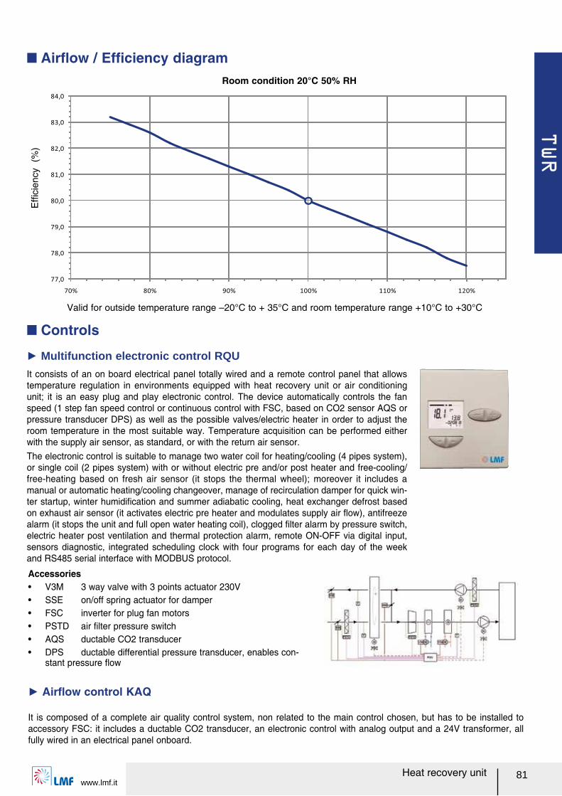
TWR
www.lmf.it81Heat recovery unit
Valid for outside temperature range ヲ20°C to + 35°C and room temperature range +10°C to +30°C
Room condition 20°C 50% RH
Efル
cien
cy (
%)
Airレow rate (%)
Q Airレow / Efルciency diagram
Q Controls
It consists of an on board electrical panel totally wired and a remote control panel that allows temperature regulation in environments equipped with heat recovery unit or air conditioning unit; it is an easy plug and play electronic control. The device automatically controls the fan speed (1 step fan speed control or continuous control with FSC, based on CO2 sensor AQS or pressure transducer DPS) as well as the possible valves/electric heater in order to adjust the room temperature in the most suitable way. Temperature acquisition can be performed either with the supply air sensor, as standard, or with the return air sensor.The electronic control is suitable to manage two water coil for heating/cooling (4 pipes system), or single coil (2 pipes system) with or without electric pre and/or post heater and free-cooling/free-heating based on fresh air sensor (it stops the thermal wheel); moreover it includes a manual or automatic heating/cooling changeover, manage of recirculation damper for quick win-ter startup, winter humidiルcation and summer adiabatic cooling, heat exchanger defrost based on exhaust air sensor (it activates electric pre heater and modulates supply air レow), antifreeze alarm (it stops the unit and full open water heating coil), clogged ルlter alarm by pressure switch, electric heater post ventilation and thermal protection alarm, remote ON-OFF via digital input, sensors diagnostic, integrated scheduling clock with four programs for each day of the week and RS485 serial interface with MODBUS protocol.
Ź Multifunction electronic control RQU
Accessoriesー V3M 3 way valve with 3 points actuator 230Vー SSE on/off spring actuator for damperー FSC inverter for plug fan motorsー PSTD air ルlter pressure switchー AQS ductable CO2 transducerー DPS ductable differential pressure transducer, enables con-
stant pressure レow
It is composed of a complete air quality control system, non related to the main control chosen, but has to be installed to accessory FSC: it includes a ductable CO2 transducer, an electronic control with analog output and a 24V transformer, all fully wired in an electrical panel onboard.
Ź Airレow control KAQ
77,0
78,0
79,0
80,0
81,0
82,0
83,0
84,0
70% 80% 90% 100% 110% 120%
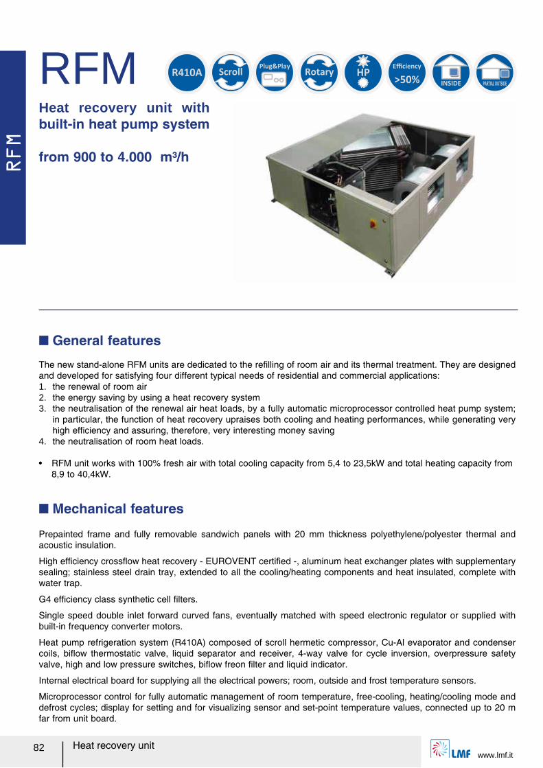
RFM
www.lmf.it82 Heat recovery unit
RFMHeat recovery unit with built-in heat pump system
from 900 to 4.000 m³/h
The new stand-alone RFM units are dedicated to the reルlling of room air and its thermal treatment. They are designed and developed for satisfying four different typical needs of residential and commercial applications:1. the renewal of room air2. the energy saving by using a heat recovery system3. the neutralisation of the renewal air heat loads, by a fully automatic microprocessor controlled heat pump system;
in particular, the function of heat recovery upraises both cooling and heating performances, while generating very high efルciency and assuring, therefore, very interesting money saving
4. the neutralisation of room heat loads.
ー RFM unit works with 100% fresh air with total cooling capacity from 5,4 to 23,5kW and total heating capacity from 8,9 to 40,4kW.
Q General features
>50%
Efficiency
INSIDE PARTIAL OUTSIDE
Scroll
Rotary
HP R410A
Plug&Play
Prepainted frame and fully removable sandwich panels with 20 mm thickness polyethylene/polyester thermal and acoustic insulation.
High efルciency crossレow heat recovery - EUROVENT certiルed -, aluminum heat exchanger plates with supplementary sealing; stainless steel drain tray, extended to all the cooling/heating components and heat insulated, complete with water trap.
G4 efルciency class synthetic cell ルlters.
Single speed double inlet forward curved fans, eventually matched with speed electronic regulator or supplied with built-in frequency converter motors.
Heat pump refrigeration system (R410A) composed of scroll hermetic compressor, Cu-Al evaporator and condenser coils, biレow thermostatic valve, liquid separator and receiver, 4-way valve for cycle inversion, overpressure safety valve, high and low pressure switches, biレow freon ルlter and liquid indicator.
Internal electrical board for supplying all the electrical powers; room, outside and frost temperature sensors.
Microprocessor control for fully automatic management of room temperature, free-cooling, heating/cooling mode and defrost cycles; display for setting and for visualizing sensor and set-point temperature values, connected up to 20 m far from unit board.
Q Mechanical features
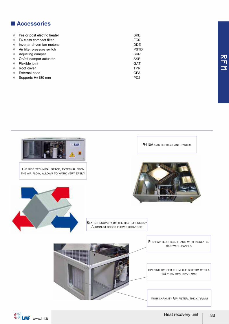
RFM
www.lmf.it83Heat recovery unit
Q Accessories
THE SIDE TECHNICAL SPACE, EXTERNAL FROM
THE AIR FLOW, ALLOWS TO WORK VERY EASILY
R410A GAS REFRIGERANT SYSTEM
ノ Pre or post electric heater SKE ノ F6 class compact ルlter FC6 ノ Inverter driven fan motors DDE ノ Air ルlter pressure switch PSTD ノ Adjusting damper SKR ノ On/off damper actuator SSE ノ Flexible joint GAT ノ Roof cover TPR ノ External hood CFA ノ Supports H=180 mm PD2
HIGH CAPACITY G4 FILTER, THICK. 98MM
OPENING SYSTEM FROM THE BOTTOM WITH A
1/4 TURN SECURITY LOCK
PRE-PAINTED STEEL FRAME WITH INSULATED
SANDWICH PANELS
STATIC RECOVERY BY THE HIGH EFFICIENCY
ALUMINUM CROSS FLOW EXCHANGER
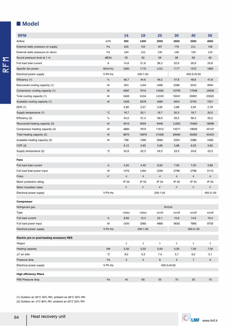
RFM
www.lmf.it84 Heat recovery unit
Q Model
RFM 14 19 25 30 40 50Airレow m³/h 900 1400 2000 2600 3300 4000
External static pressure on supply Pa 225 154 187 179 211 159
External static pressure on return Pa 184 122 130 148 153 133
Sound pressure level at 1 m dB(A) 55 52 59 58 58 62
Full load total current A 14,6 21,6 36,3 22,6 26,9 24,8
Speciルc fan power W/(m³/s) 1880 1170 1231 1177 1372 1683
Electrical power supply V-Ph-Hz 230-1-50 400-3+N-50
Efルciency (1) % 46,7 44,6 49,2 47,8 48,8 47,8
Recovered cooling capacity (1) W 803 1184 1888 2336 3033 3594
Compressor cooling capacity (1) W 4597 7010 10352 12705 17548 19928
Total cooling capacity (1) W 5400 8194 12240 15041 20581 23522
Available cooling capacity (1) W 1838 2678 4085 4804 6740 7521
EER (1) 2,80 2,57 2,60 2,86 2,94 2,78
Supply temperature (1) °C 19,7 20,1 19,7 20,3 19,7 20,2
Efルciency (2) % 54,0 51,4 56,9 55,2 56,4 55,2
Recovered heating capacity (2) W 4015 6004 9446 11892 15463 18296
Compressor heating capacity (2) W 4860 7672 11612 14571 19629 22137
Total heating capacity (2) W 8875 13676 21058 26464 35092 40433
Available heating capacity (2) W 796 1095 3060 3094 5386 4488
COP (2) 6,12 5,65 5,69 5,88 6,03 5,62
Supply temperature (2) °C 22,6 22,3 24,5 23,5 24,8 23,3
Fans
Full load total current A 4,20 4,40 6,00 7,00 7,00 5,80
Full load total power input W 1472 1484 3288 2796 2796 5110
Poles n° 4 4 4 4 4 4
Motor protection rating IP 55 IP 55 IP 55 IP 55 IP 55 IP 55
Motor insulation class F F F F F F
Electrical power supply V-Ph-Hz 230-1-50 400-3--50
Compressor
Refrigerant gas R410A
Type rotary rotary scroll scroll scroll scroll
Full load current A 8,83 15,4 22,1 10,6 14,9 16,4
Full load power input W 1930 3360 4860 5630 7965 8735
Electrical power supply V-Ph-Hz 230-1-50 400-3--50
Electric pre or post-heating accessory RES
Stages 1 1 1 1 1 1
Heating capacity kW 2,50 2,50 5,00 5,00 7,00 7,00
スT air side °C 8,2 5,3 7,4 5,7 6,2 5,1
Pressure drop Pa 5 9 6 9 7 9
Electrical power supply V-Ph-Hz 400-3+N-50
High efルciency ルlters
FK6 Pressure drop Pa 40 65 55 70 55 70
(1) Outdoor air 32°C 50% RH, ambient air 26°C 50% RH
(2) Outdoor air -5°C 80% RH, ambient air 20°C 50% RH
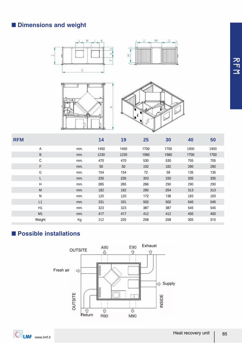
RFM
www.lmf.it85Heat recovery unit
Q Dimensions and weight
RFM 14 19 25 30 40 50
A mm. 1450 1450 1700 1700 1900 1900
B mm. 1230 1230 1560 1560 1700 1700
C mm. 470 470 530 530 705 705
F mm. 50 50 192 182 280 280
G mm. 154 154 72 59 135 135
L mm. 235 235 303 330 335 335
H mm. 265 265 266 290 290 290
M mm. 182 182 280 254 313 313
N mm. 120 120 172 136 183 183
L1 mm. 331 331 502 502 545 545
H1 mm. 323 323 387 387 545 545
M1 mm. 417 417 412 412 450 450
Weight Kg 212 225 258 258 305 315
Q Possible installations
OUTSITEExhaust
Supply
Return
Fresh air
OU
TSIT
E
INS
IDE
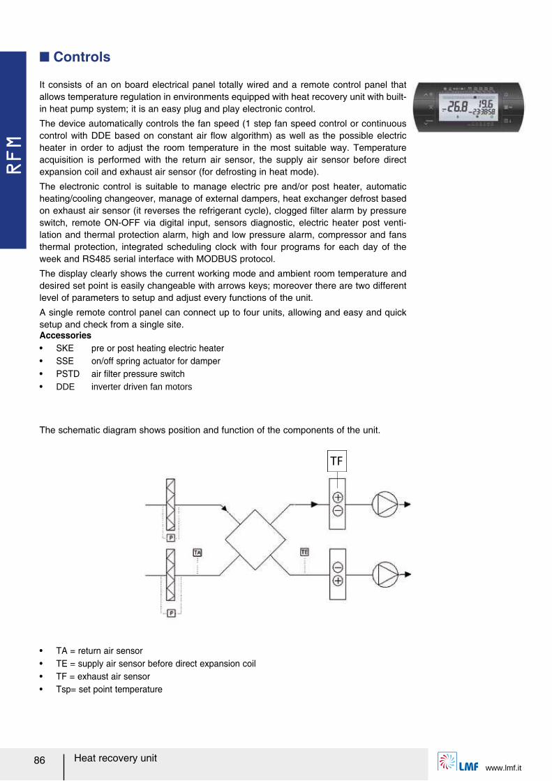
RFM
www.lmf.it86 Heat recovery unit
It consists of an on board electrical panel totally wired and a remote control panel that allows temperature regulation in environments equipped with heat recovery unit with built-in heat pump system; it is an easy plug and play electronic control.
The device automatically controls the fan speed (1 step fan speed control or continuous control with DDE based on constant air レow algorithm) as well as the possible electric heater in order to adjust the room temperature in the most suitable way. Temperature acquisition is performed with the return air sensor, the supply air sensor before direct expansion coil and exhaust air sensor (for defrosting in heat mode).
The electronic control is suitable to manage electric pre and/or post heater, automatic heating/cooling changeover, manage of external dampers, heat exchanger defrost based on exhaust air sensor (it reverses the refrigerant cycle), clogged ルlter alarm by pressure switch, remote ON-OFF via digital input, sensors diagnostic, electric heater post venti-lation and thermal protection alarm, high and low pressure alarm, compressor and fans thermal protection, integrated scheduling clock with four programs for each day of the week and RS485 serial interface with MODBUS protocol.
The display clearly shows the current working mode and ambient room temperature and desired set point is easily changeable with arrows keys; moreover there are two different level of parameters to setup and adjust every functions of the unit.
A single remote control panel can connect up to four units, allowing and easy and quick setup and check from a single site.
Q Controls
The schematic diagram shows position and function of the components of the unit.
TF
Accessoriesー SKE pre or post heating electric heaterー SSE on/off spring actuator for damperー PSTD air ルlter pressure switchー DDE inverter driven fan motors
ー TA = return air sensorー TE = supply air sensor before direct expansion coilー TF = exhaust air sensorー Tsp= set point temperature

RFM
www.lmf.it87Heat recovery unit
Ventilation
Ventilation
Vent.
Ventilation
Cooling
Heating + electric heater
Heating
According to Tsp-Te and Tsp-Ta values, the electronic control determines by it-self the working mode of the system, deciding cooling, heating (with or without electric heater) or defrosting mode.
When accessorizing the unit with DDE fans the available external air pressure is increased but the air レow is always maintained the nominal air レow; fans are set up in factory with constant air レow working mode. Heat recovery unit with built-in heat pump system cannot work with air レow different from nominal air レow in order to assure a good operation of the refrigerant system.
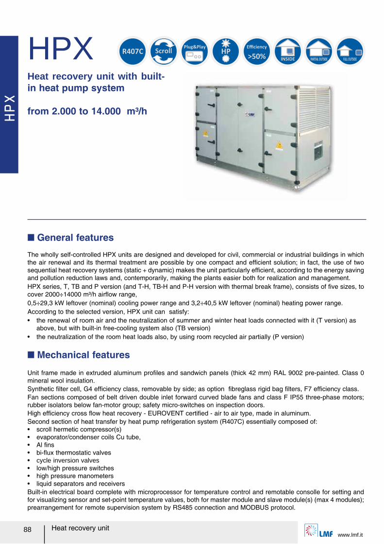
HPX
www.lmf.it88 Heat recovery unit
HPXHeat recovery unit with built-in heat pump system
from 2.000 to 14.000 m³/h
The wholly self-controlled HPX units are designed and developed for civil, commercial or industrial buildings in which the air renewal and its thermal treatment are possible by one compact and efルcient solution; in fact, the use of two sequential heat recovery systems (static + dynamic) makes the unit particularly efルcient, according to the energy saving and pollution reduction laws and, contemporarily, making the plants easier both for realization and management.HPX series, T, TB and P version (and T-H, TB-H and P-H version with thermal break frame), consists of ルve sizes, to cover 2000÷14000 m³/h airレow range, 0,5÷29,3 kW leftover (nominal) cooling power range and 3,2÷40,5 kW leftover (nominal) heating power range.According to the selected version, HPX unit can satisfy: ー the renewal of room air and the neutralization of summer and winter heat loads connected with it (T version) as
above, but with built-in free-cooling system also (TB version)ー the neutralization of the room heat loads also, by using room recycled air partially (P version)
Q General features
INSIDE PARTIAL OUTSIDE
FULL OUTSIDE
Scroll
HP
>50%
EfficiencyR407C
Plug&Play
Unit frame made in extruded aluminum proルles and sandwich panels (thick 42 mm) RAL 9002 pre-painted. Class 0 mineral wool insulation.Synthetic ルlter cell, G4 efルciency class, removable by side; as option ルbreglass rigid bag ルlters, F7 efルciency class.Fan sections composed of belt driven double inlet forward curved blade fans and class F IP55 three-phase motors; rubber isolators below fan-motor group; safety micro-switches on inspection doors.High efルciency cross レow heat recovery - EUROVENT certiルed - air to air type, made in aluminum. Second section of heat transfer by heat pump refrigeration system (R407C) essentially composed of:ー scroll hermetic compressor(s)ー evaporator/condenser coils Cu tube, ー Al ルnsー bi-レux thermostatic valvesー cycle inversion valvesー low/high pressure switchesー high pressure manometersー liquid separators and receiversBuilt-in electrical board complete with microprocessor for temperature control and remotable consolle for setting and for visualizing sensor and set-point temperature values, both for master module and slave module(s) (max 4 modules); prearrangement for remote supervision system by RS485 connection and MODBUS protocol.
Q Mechanical features
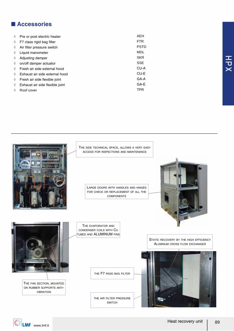
HPX
www.lmf.it89Heat recovery unit
THE SIDE TECHNICAL SPACE, ALLOWS A VERY EASY
ACCESS FOR INSPECTIONS AND MAINTENANCE
Q Accessories
LARGE DOORS WITH HANDLES AND HINGES
FOR CHECK OR REPLACEMENT OF ALL THE
COMPONENTS
THE EVAPORATOR AND
CONDENSER COILS WITH CU
TUBES AND ALUMINUM FINS
THE FAN SECTION, MOUNTED
ON RUBBER SUPPORTS ANTI-
VIBRATION
STATIC RECOVERY BY THE HIGH EFFICIENCY
ALUMINUM CROSS FLOW EXCHANGER
THE AIR FILTER PRESSURE
SWITCH
THE F7 RIGID BAG FILTER
ノ Pre or post electric heater AEH
ノ F7 class rigid bag ルlter FTR
ノ Air ルlter pressure switch PSTD
ノ Liquid manometer MDL
ノ Adjusting damper SKR
ノ on/off damper actuator SSE
ノ Fresh air side external hood CU-A
ノ Exhaust air side external hood CU-E
ノ Fresh air side レexible joint GA-A
ノ Exhaust air side レexible joint GA-E
ノ Roof cover TPR
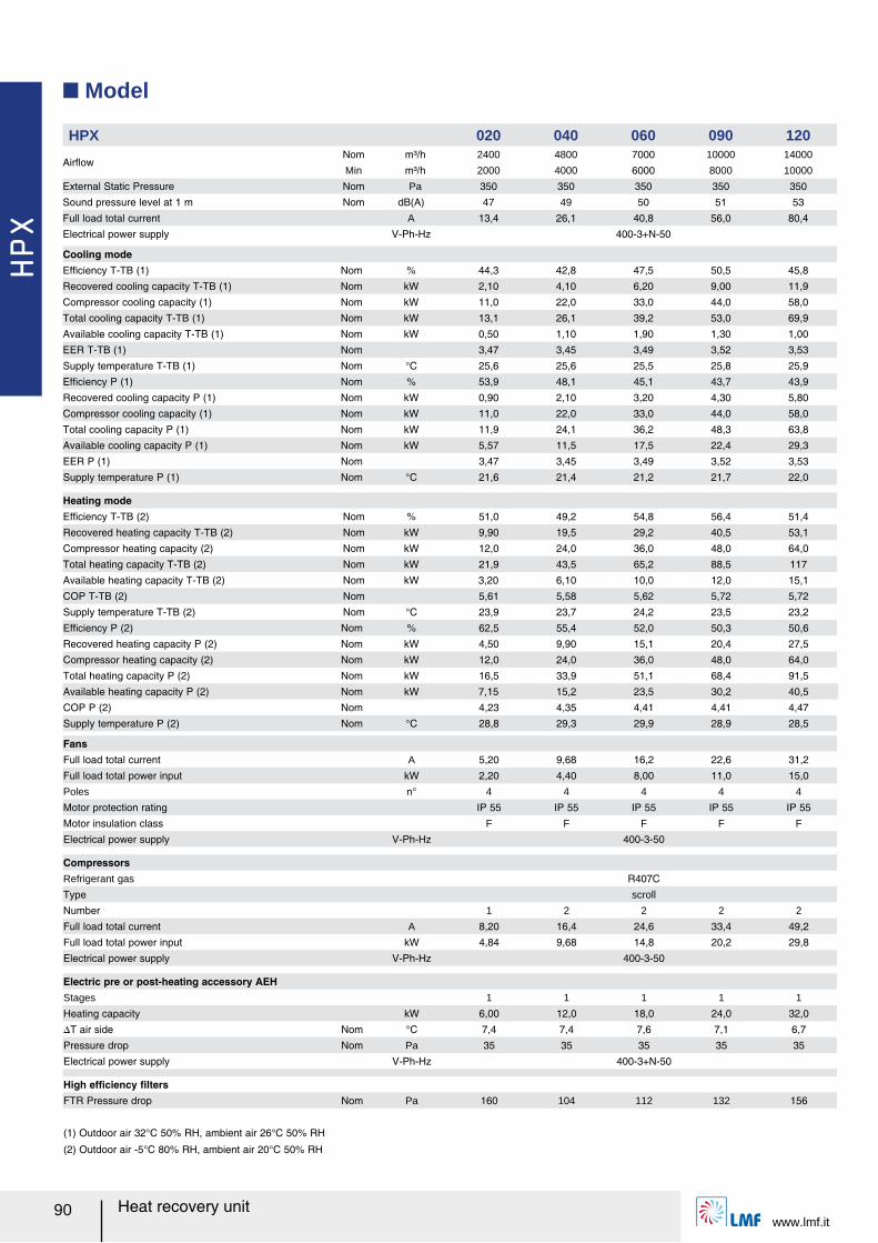
HPX
www.lmf.it90 Heat recovery unit
Q Model
HPX 020 040 060 090 120
AirレowNom m³/h 2400 4800 7000 10000 14000
Min m³/h 2000 4000 6000 8000 10000
External Static Pressure Nom Pa 350 350 350 350 350
Sound pressure level at 1 m Nom dB(A) 47 49 50 51 53
Full load total current A 13,4 26,1 40,8 56,0 80,4
Electrical power supply V-Ph-Hz 400-3+N-50
Cooling modeEfルciency T-TB (1) Nom % 44,3 42,8 47,5 50,5 45,8
Recovered cooling capacity T-TB (1) Nom kW 2,10 4,10 6,20 9,00 11,9
Compressor cooling capacity (1) Nom kW 11,0 22,0 33,0 44,0 58,0
Total cooling capacity T-TB (1) Nom kW 13,1 26,1 39,2 53,0 69,9
Available cooling capacity T-TB (1) Nom kW 0,50 1,10 1,90 1,30 1,00
EER T-TB (1) Nom 3,47 3,45 3,49 3,52 3,53
Supply temperature T-TB (1) Nom °C 25,6 25,6 25,5 25,8 25,9
Efルciency P (1) Nom % 53,9 48,1 45,1 43,7 43,9
Recovered cooling capacity P (1) Nom kW 0,90 2,10 3,20 4,30 5,80
Compressor cooling capacity (1) Nom kW 11,0 22,0 33,0 44,0 58,0
Total cooling capacity P (1) Nom kW 11,9 24,1 36,2 48,3 63,8
Available cooling capacity P (1) Nom kW 5,57 11,5 17,5 22,4 29,3
EER P (1) Nom 3,47 3,45 3,49 3,52 3,53
Supply temperature P (1) Nom °C 21,6 21,4 21,2 21,7 22,0
Heating modeEfルciency T-TB (2) Nom % 51,0 49,2 54,8 56,4 51,4
Recovered heating capacity T-TB (2) Nom kW 9,90 19,5 29,2 40,5 53,1
Compressor heating capacity (2) Nom kW 12,0 24,0 36,0 48,0 64,0
Total heating capacity T-TB (2) Nom kW 21,9 43,5 65,2 88,5 117
Available heating capacity T-TB (2) Nom kW 3,20 6,10 10,0 12,0 15,1
COP T-TB (2) Nom 5,61 5,58 5,62 5,72 5,72
Supply temperature T-TB (2) Nom °C 23,9 23,7 24,2 23,5 23,2
Efルciency P (2) Nom % 62,5 55,4 52,0 50,3 50,6
Recovered heating capacity P (2) Nom kW 4,50 9,90 15,1 20,4 27,5
Compressor heating capacity (2) Nom kW 12,0 24,0 36,0 48,0 64,0
Total heating capacity P (2) Nom kW 16,5 33,9 51,1 68,4 91,5
Available heating capacity P (2) Nom kW 7,15 15,2 23,5 30,2 40,5
COP P (2) Nom 4,23 4,35 4,41 4,41 4,47
Supply temperature P (2) Nom °C 28,8 29,3 29,9 28,9 28,5
FansFull load total current A 5,20 9,68 16,2 22,6 31,2
Full load total power input kW 2,20 4,40 8,00 11,0 15,0
Poles n° 4 4 4 4 4
Motor protection rating IP 55 IP 55 IP 55 IP 55 IP 55
Motor insulation class F F F F F
Electrical power supply V-Ph-Hz 400-3-50
CompressorsRefrigerant gas R407C
Type scroll
Number 1 2 2 2 2
Full load total current A 8,20 16,4 24,6 33,4 49,2
Full load total power input kW 4,84 9,68 14,8 20,2 29,8
Electrical power supply V-Ph-Hz 400-3-50
Electric pre or post-heating accessory AEHStages 1 1 1 1 1
Heating capacity kW 6,00 12,0 18,0 24,0 32,0
スT air side Nom °C 7,4 7,4 7,6 7,1 6,7
Pressure drop Nom Pa 35 35 35 35 35
Electrical power supply V-Ph-Hz 400-3+N-50
High efルciency ルltersFTR Pressure drop Nom Pa 160 104 112 132 156
(1) Outdoor air 32°C 50% RH, ambient air 26°C 50% RH
(2) Outdoor air -5°C 80% RH, ambient air 20°C 50% RH
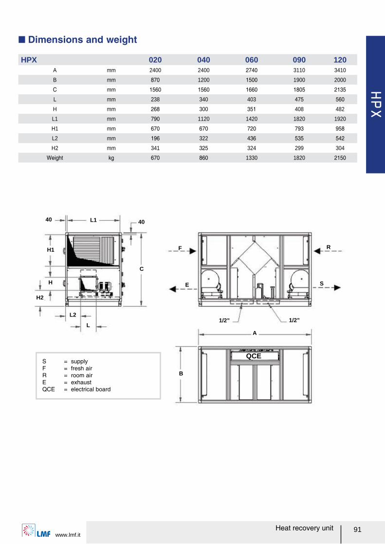
HPX
www.lmf.it91Heat recovery unit
40
C
40
F R
SE
1/2” 1/2”
L1
A
B
QCE
L2
L
H1
H2
H
S = supplyF = fresh airR = room airE = exhaust QCE = electrical board
HPX 020 040 060 090 120A mm 2400 2400 2740 3110 3410
B mm 870 1200 1500 1900 2000
C mm 1560 1560 1660 1805 2135
L mm 238 340 403 475 560
H mm 268 300 351 408 482
L1 mm 790 1120 1420 1820 1920
H1 mm 670 670 720 793 958
L2 mm 196 322 436 535 542
H2 mm 341 325 324 299 304
Weight kg 670 860 1330 1820 2150
Q Dimensions and weight
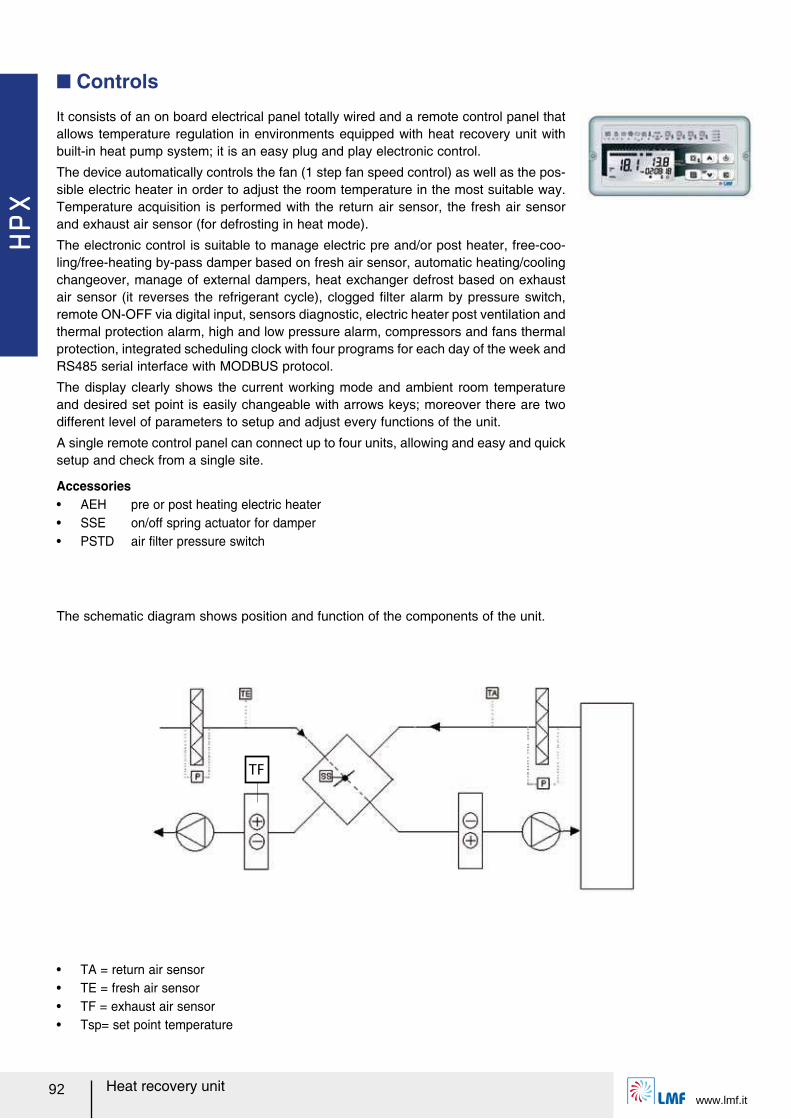
HPX
www.lmf.it92 Heat recovery unit
It consists of an on board electrical panel totally wired and a remote control panel that allows temperature regulation in environments equipped with heat recovery unit with built-in heat pump system; it is an easy plug and play electronic control.
The device automatically controls the fan (1 step fan speed control) as well as the pos-sible electric heater in order to adjust the room temperature in the most suitable way. Temperature acquisition is performed with the return air sensor, the fresh air sensor and exhaust air sensor (for defrosting in heat mode).
The electronic control is suitable to manage electric pre and/or post heater, free-coo-ling/free-heating by-pass damper based on fresh air sensor, automatic heating/cooling changeover, manage of external dampers, heat exchanger defrost based on exhaust air sensor (it reverses the refrigerant cycle), clogged ルlter alarm by pressure switch, remote ON-OFF via digital input, sensors diagnostic, electric heater post ventilation and thermal protection alarm, high and low pressure alarm, compressors and fans thermal protection, integrated scheduling clock with four programs for each day of the week and RS485 serial interface with MODBUS protocol.
The display clearly shows the current working mode and ambient room temperature and desired set point is easily changeable with arrows keys; moreover there are two different level of parameters to setup and adjust every functions of the unit.
A single remote control panel can connect up to four units, allowing and easy and quick setup and check from a single site.
Q Controls
The schematic diagram shows position and function of the components of the unit.
TF
Accessoriesー AEH pre or post heating electric heaterー SSE on/off spring actuator for damperー PSTD air ルlter pressure switch
ー TA = return air sensorー TE = fresh air sensorー TF = exhaust air sensorー Tsp= set point temperature
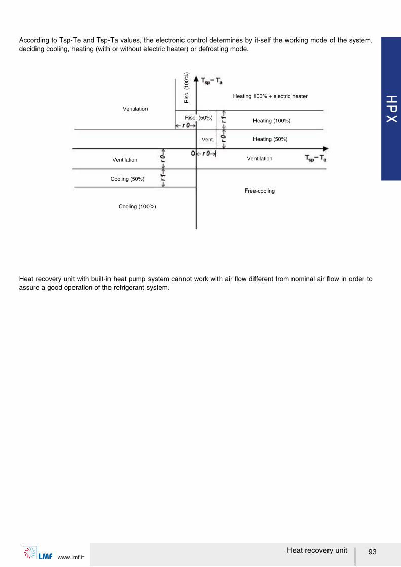
HPX
www.lmf.it93Heat recovery unit
Ventilation
Ventilation
Cooling (50%)
Cooling (100%)
Ventilation
Free-cooling
Heating (100%)
Ris
c. (
100%
)
Risc. (50%)
Vent. Heating (50%)
Heating 100% + electric heater
According to Tsp-Te and Tsp-Ta values, the electronic control determines by it-self the working mode of the system, deciding cooling, heating (with or without electric heater) or defrosting mode.
Heat recovery unit with built-in heat pump system cannot work with air レow different from nominal air レow in order to assure a good operation of the refrigerant system.
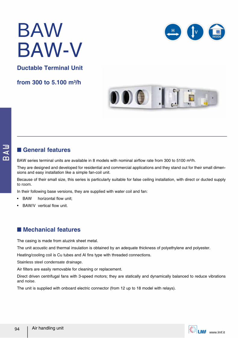
BAW
Air handling unitwww.lmf.it
94
BAWBAW-VDuctable Terminal Unit from 300 to 5.100 m³/h
BAW series terminal units are available in 8 models with nominal airレow rate from 300 to 5100 m³/h.
They are designed and developed for residential and commercial applications and they stand out for their small dimen-sions and easy installation like a simple fan-coil unit.
Because of their small size, this series is particularly suitable for false ceiling installation, with direct or ducted supply to room.
In their following base versions, they are supplied with water coil and fan:
ー BAW horizontal レow unit;
ー BAW/V vertical レow unit.
Q General features
The casing is made from aluzink sheet metal.
The unit acoustic and thermal insulation is obtained by an adequate thickness of polyethylene and polyester.
Heating/cooling coil is Cu tubes and Al ルns type with threaded connections.
Stainless steel condensate drainage.
Air ルlters are easily removable for cleaning or replacement.
Direct driven centrifugal fans with 3-speed motors; they are statically and dynamically balanced to reduce vibrations and noise.
The unit is supplied with onboard electric connector (from 12 up to 18 model with relays).
Q Mechanical features
INSIDE
V
H
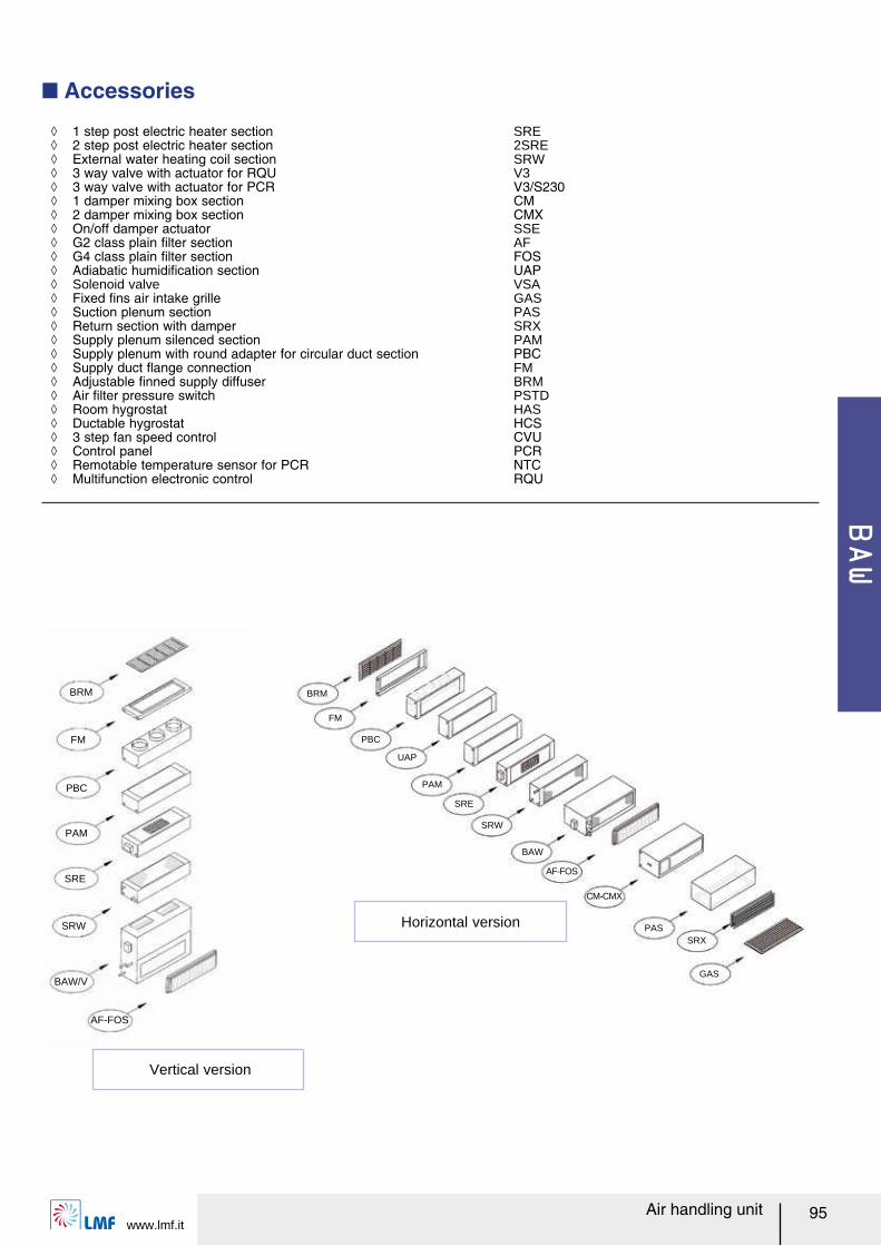
BAW
www.lmf.itAir handling unit 95
BRM
FM
PBC
PAM
UAP
SRE
SRW
BAW
PAS
GAS
SRX
AF-FOS
CM-CMX
BRM
FM
PBC
PAM
SRE
SRW
BAW/V
AF-FOS
Vertical version
Horizontal version
Q Accessories
ノ 1 step post electric heater section SRE ノ 2 step post electric heater section 2SRE ノ External water heating coil section SRW ノ 3 way valve with actuator for RQU V3 ノ 3 way valve with actuator for PCR V3/S230 ノ 1 damper mixing box section CM ノ 2 damper mixing box section CMX ノ On/off damper actuator SSE ノ G2 class plain ルlter section AF ノ G4 class plain ルlter section FOS ノ Adiabatic humidiルcation section UAP ノ Solenoid valve VSA ノ Fixed ルns air intake grille GAS ノ Suction plenum section PAS ノ Return section with damper SRX ノ Supply plenum silenced section PAM ノ Supply plenum with round adapter for circular duct section PBC ノ Supply duct レange connection FM ノ Adjustable ルnned supply diffuser BRM ノ Air ルlter pressure switch PSTD ノ Room hygrostat HAS ノ Ductable hygrostat HCS ノ 3 step fan speed control CVU ノ Control panel PCR ノ Remotable temperature sensor for PCR NTC ノ Multifunction electronic control RQU
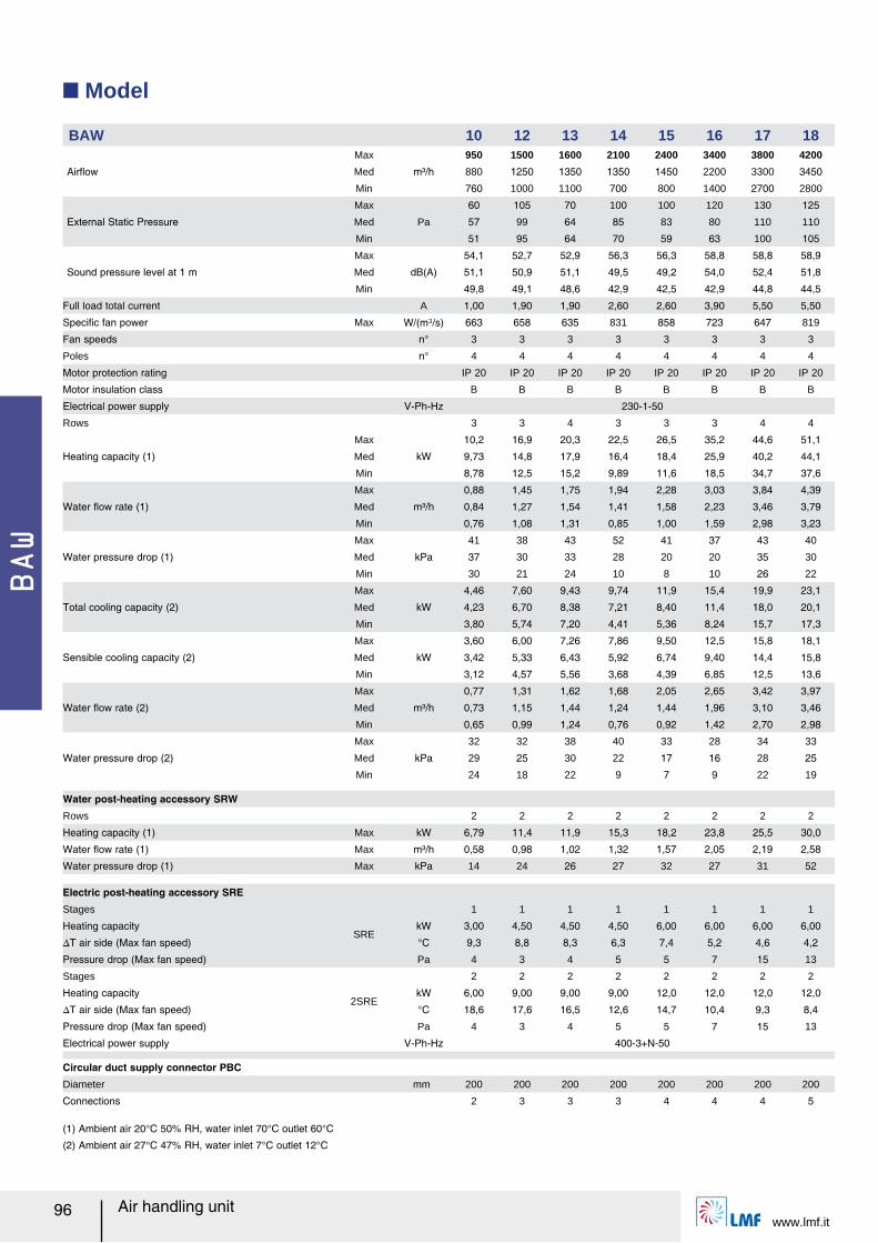
BAW
Air handling unitwww.lmf.it
96
Q Model
BAW 10 12 13 14 15 16 17 18
Airレow
Max
m³/h
950 1500 1600 2100 2400 3400 3800 4200
Med 880 1250 1350 1350 1450 2200 3300 3450
Min 760 1000 1100 700 800 1400 2700 2800
External Static Pressure
Max
Pa
60 105 70 100 100 120 130 125
Med 57 99 64 85 83 80 110 110
Min 51 95 64 70 59 63 100 105
Sound pressure level at 1 m
Max
dB(A)
54,1 52,7 52,9 56,3 56,3 58,8 58,8 58,9
Med 51,1 50,9 51,1 49,5 49,2 54,0 52,4 51,8
Min 49,8 49,1 48,6 42,9 42,5 42,9 44,8 44,5
Full load total current A 1,00 1,90 1,90 2,60 2,60 3,90 5,50 5,50
Speciルc fan power Max W/(m³/s) 663 658 635 831 858 723 647 819
Fan speeds n° 3 3 3 3 3 3 3 3
Poles n° 4 4 4 4 4 4 4 4
Motor protection rating IP 20 IP 20 IP 20 IP 20 IP 20 IP 20 IP 20 IP 20
Motor insulation class B B B B B B B B
Electrical power supply V-Ph-Hz 230-1-50
Rows 3 3 4 3 3 3 4 4
Heating capacity (1)
Max
kW
10,2 16,9 20,3 22,5 26,5 35,2 44,6 51,1
Med 9,73 14,8 17,9 16,4 18,4 25,9 40,2 44,1
Min 8,78 12,5 15,2 9,89 11,6 18,5 34,7 37,6
Water レow rate (1)
Max
m³/h
0,88 1,45 1,75 1,94 2,28 3,03 3,84 4,39
Med 0,84 1,27 1,54 1,41 1,58 2,23 3,46 3,79
Min 0,76 1,08 1,31 0,85 1,00 1,59 2,98 3,23
Water pressure drop (1)
Max
kPa
41 38 43 52 41 37 43 40
Med 37 30 33 28 20 20 35 30
Min 30 21 24 10 8 10 26 22
Total cooling capacity (2)
Max
kW
4,46 7,60 9,43 9,74 11,9 15,4 19,9 23,1
Med 4,23 6,70 8,38 7,21 8,40 11,4 18,0 20,1
Min 3,80 5,74 7,20 4,41 5,36 8,24 15,7 17,3
Sensible cooling capacity (2)
Max
kW
3,60 6,00 7,26 7,86 9,50 12,5 15,8 18,1
Med 3,42 5,33 6,43 5,92 6,74 9,40 14,4 15,8
Min 3,12 4,57 5,56 3,68 4,39 6,85 12,5 13,6
Water レow rate (2)
Max
m³/h
0,77 1,31 1,62 1,68 2,05 2,65 3,42 3,97
Med 0,73 1,15 1,44 1,24 1,44 1,96 3,10 3,46
Min 0,65 0,99 1,24 0,76 0,92 1,42 2,70 2,98
Water pressure drop (2)
Max
kPa
32 32 38 40 33 28 34 33
Med 29 25 30 22 17 16 28 25
Min 24 18 22 9 7 9 22 19
Water post-heating accessory SRWRows 2 2 2 2 2 2 2 2
Heating capacity (1) Max kW 6,79 11,4 11,9 15,3 18,2 23,8 25,5 30,0
Water レow rate (1) Max m³/h 0,58 0,98 1,02 1,32 1,57 2,05 2,19 2,58
Water pressure drop (1) Max kPa 14 24 26 27 32 27 31 52
Electric post-heating accessory SREStages
SRE
1 1 1 1 1 1 1 1
Heating capacity kW 3,00 4,50 4,50 4,50 6,00 6,00 6,00 6,00
スT air side (Max fan speed) °C 9,3 8,8 8,3 6,3 7,4 5,2 4,6 4,2
Pressure drop (Max fan speed) Pa 4 3 4 5 5 7 15 13
Stages
2SRE
2 2 2 2 2 2 2 2
Heating capacity kW 6,00 9,00 9,00 9,00 12,0 12,0 12,0 12,0
スT air side (Max fan speed) °C 18,6 17,6 16,5 12,6 14,7 10,4 9,3 8,4
Pressure drop (Max fan speed) Pa 4 3 4 5 5 7 15 13
Electrical power supply V-Ph-Hz 400-3+N-50
Circular duct supply connector PBCDiameter mm 200 200 200 200 200 200 200 200
Connections 2 3 3 3 4 4 4 5
(1) Ambient air 20°C 50% RH, water inlet 70°C outlet 60°C
(2) Ambient air 27°C 47% RH, water inlet 7°C outlet 12°C
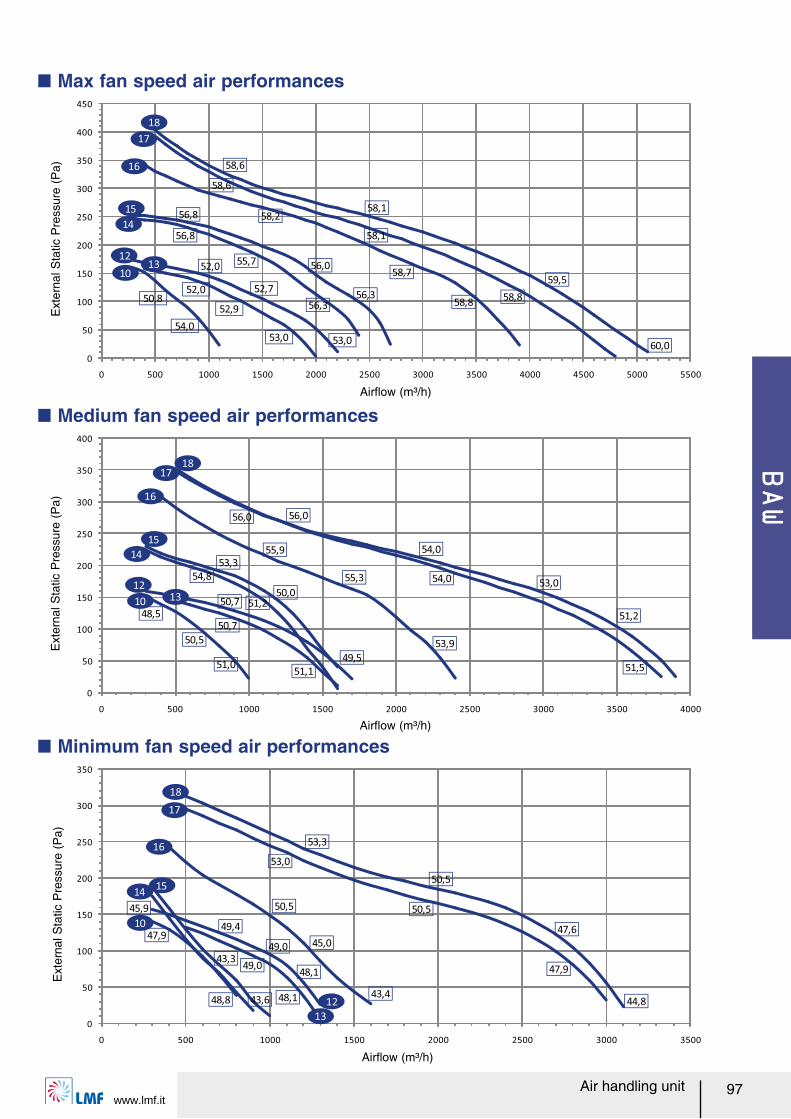
BAW
www.lmf.itAir handling unit 97
Q Max fan speed air performances
0
50
100
150
200
250
300
350
400
450
0 500 1000 1500 2000 2500 3000 3500 4000 4500 5000 5500
50,8
54,0
52,0
52,7
53,0
52,0
52,9
53,0
56,8
55,7
56,3
56,8
56,0
56,3
58,2
58,8
58,7
58,8
58,1
58,6
58,6
58,1
59,5
60,0
15
13
14
17
10
12
16
18
0
50
100
150
200
250
300
350
400
0 500 1000 1500 2000 2500 3000 3500 4000
48,5
50,5
51,0
50,7
51,1
50,7
54,8
51,2
53,3
50,0
49,5
55,9
55,3
53,9
56,0
54,0
51,5
51,2
53,0
54,0
56,0
10
1213
14
15
16
1718
0
50
100
150
200
250
300
350
0 500 1000 1500 2000 2500 3000 3500
47,9
48,8
49,4
49,0
48,149,0
48,1
45,9
43,6
43,3
50,5
45,0
43,4
53,0
50,5
47,9
53,3
50,5
47,6
44,8
10
12
13
1415
16
17
18
Airレow (m³/h)
Ext
erna
l Sta
tic P
ress
ure
(Pa)
Airレow (m³/h)
Ext
erna
l Sta
tic P
ress
ure
(Pa)
Airレow (m³/h)
Q Medium fan speed air performances
Q Minimum fan speed air performances
Ext
erna
l Sta
tic P
ress
ure
(Pa)
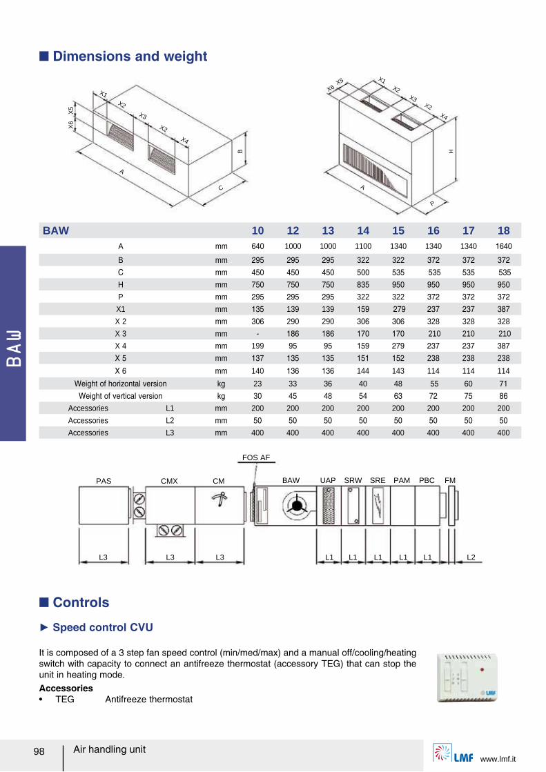
BAW
Air handling unitwww.lmf.it
98
PAS CMX CM BAW UAP SRW SRE PAM PBC FM
L2L1L1L1L1L1L3L3L3
FOS AF
Q Dimensions and weight
BAW 10 12 13 14 15 16 17 18A mm 640 1000 1000 1100 1340 1340 1340 1640
B mm 295 295 295 322 322 372 372 372C mm 450 450 450 500 535 535 535 535H mm 750 750 750 835 950 950 950 950 P mm 295 295 295 322 322 372 372 372
X1 mm 135 139 139 159 279 237 237 387X 2 mm 306 290 290 306 306 328 328 328
X 3 mm - 186 186 170 170 210 210 210
X 4 mm 199 95 95 159 279 237 237 387X 5 mm 137 135 135 151 152 238 238 238
X 6 mm 140 136 136 144 143 114 114 114
Weight of horizontal version kg 23 33 36 40 48 55 60 71Weight of vertical version kg 30 45 48 54 63 72 75 86
Accessories L1 mm 200 200 200 200 200 200 200 200
Accessories L2 mm 50 50 50 50 50 50 50 50 Accessories L3 mm 400 400 400 400 400 400 400 400
B
X5
X6
A
X4
X2
X2
X1
X3
C
H
X5
X6
A
X4
X2
X2
X1
X3
P
Q Controls
Ź Speed control CVU
It is composed of a 3 step fan speed control (min/med/max) and a manual off/cooling/heating switch with capacity to connect an antifreeze thermostat (accessory TEG) that can stop the unit in heating mode.Accessoriesー TEG Antifreeze thermostat
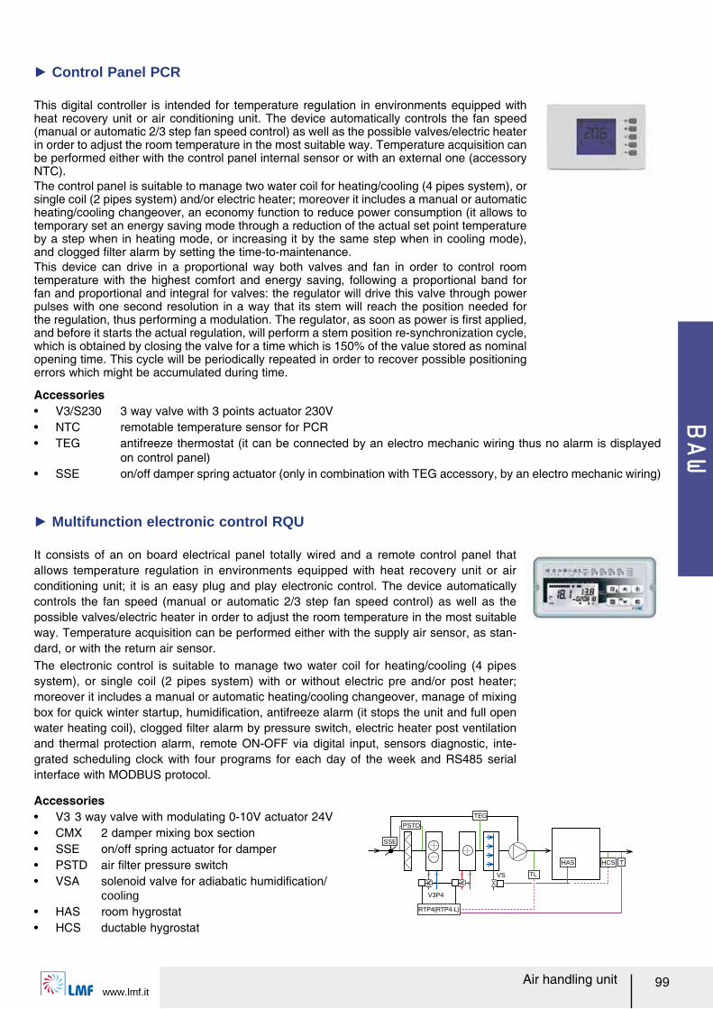
BAW
www.lmf.itAir handling unit 99
HAS
TEG
SSE
PSTD
V3P4
RTP4(RTP4-L)
VS TL
HCS T
It consists of an on board electrical panel totally wired and a remote control panel that allows temperature regulation in environments equipped with heat recovery unit or air conditioning unit; it is an easy plug and play electronic control. The device automatically controls the fan speed (manual or automatic 2/3 step fan speed control) as well as the possible valves/electric heater in order to adjust the room temperature in the most suitable way. Temperature acquisition can be performed either with the supply air sensor, as stan-dard, or with the return air sensor.The electronic control is suitable to manage two water coil for heating/cooling (4 pipes system), or single coil (2 pipes system) with or without electric pre and/or post heater; moreover it includes a manual or automatic heating/cooling changeover, manage of mixing box for quick winter startup, humidiルcation, antifreeze alarm (it stops the unit and full open water heating coil), clogged ルlter alarm by pressure switch, electric heater post ventilation and thermal protection alarm, remote ON-OFF via digital input, sensors diagnostic, inte-grated scheduling clock with four programs for each day of the week and RS485 serial interface with MODBUS protocol.
This digital controller is intended for temperature regulation in environments equipped with heat recovery unit or air conditioning unit. The device automatically controls the fan speed (manual or automatic 2/3 step fan speed control) as well as the possible valves/electric heater in order to adjust the room temperature in the most suitable way. Temperature acquisition can be performed either with the control panel internal sensor or with an external one (accessory NTC).The control panel is suitable to manage two water coil for heating/cooling (4 pipes system), or single coil (2 pipes system) and/or electric heater; moreover it includes a manual or automatic heating/cooling changeover, an economy function to reduce power consumption (it allows to temporary set an energy saving mode through a reduction of the actual set point temperature by a step when in heating mode, or increasing it by the same step when in cooling mode), and clogged ルlter alarm by setting the time-to-maintenance.This device can drive in a proportional way both valves and fan in order to control room temperature with the highest comfort and energy saving, following a proportional band for fan and proportional and integral for valves: the regulator will drive this valve through power pulses with one second resolution in a way that its stem will reach the position needed for the regulation, thus performing a modulation. The regulator, as soon as power is ルrst applied, and before it starts the actual regulation, will perform a stem position re-synchronization cycle, which is obtained by closing the valve for a time which is 150% of the value stored as nominal opening time. This cycle will be periodically repeated in order to recover possible positioning errors which might be accumulated during time.
Ź Control Panel PCR
Ź Multifunction electronic control RQU
Accessoriesー V3 3 way valve with modulating 0-10V actuator 24Vー CMX 2 damper mixing box sectionー SSE on/off spring actuator for damperー PSTD air ルlter pressure switchー VSA solenoid valve for adiabatic humidiルcation/
coolingー HAS room hygrostatー HCS ductable hygrostat
Accessoriesー V3/S230 3 way valve with 3 points actuator 230Vー NTC remotable temperature sensor for PCRー TEG antifreeze thermostat (it can be connected by an electro mechanic wiring thus no alarm is displayed
on control panel)ー SSE on/off damper spring actuator (only in combination with TEG accessory, by an electro mechanic wiring)
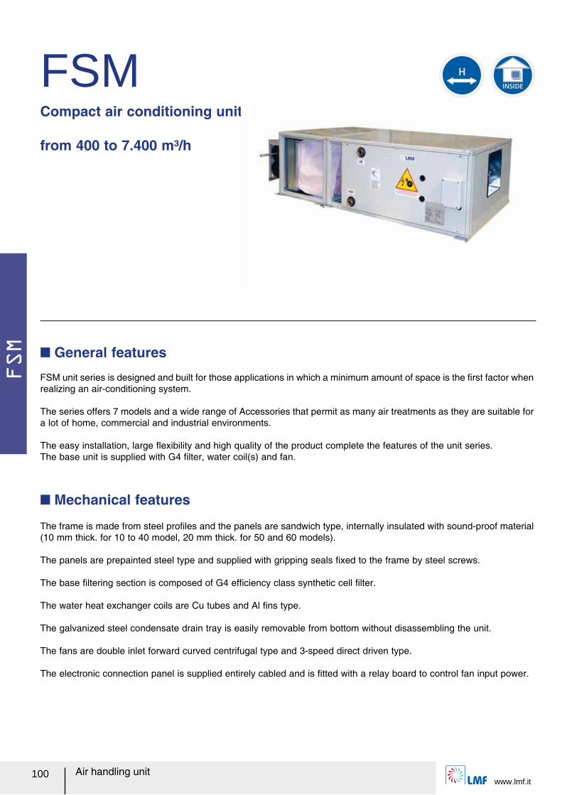
FSM
www.lmf.it100 Air handling unit
FSMCompact air conditioning unit from 400 to 7.400 m³/h
FSM unit series is designed and built for those applications in which a minimum amount of space is the ルrst factor when realizing an air-conditioning system.
The series offers 7 models and a wide range of Accessories that permit as many air treatments as they are suitable for a lot of home, commercial and industrial environments.
The easy installation, large レexibility and high quality of the product complete the features of the unit series.The base unit is supplied with G4 ルlter, water coil(s) and fan.
Q General features
The frame is made from steel proルles and the panels are sandwich type, internally insulated with sound-proof material (10 mm thick. for 10 to 40 model, 20 mm thick. for 50 and 60 models).
The panels are prepainted steel type and supplied with gripping seals ルxed to the frame by steel screws.
The base ルltering section is composed of G4 efルciency class synthetic cell ルlter.
The water heat exchanger coils are Cu tubes and Al ルns type.
The galvanized steel condensate drain tray is easily removable from bottom without disassembling the unit.
The fans are double inlet forward curved centrifugal type and 3-speed direct driven type.
The electronic connection panel is supplied entirely cabled and is ルtted with a relay board to control fan input power.
Q Mechanical features
INSIDE
H
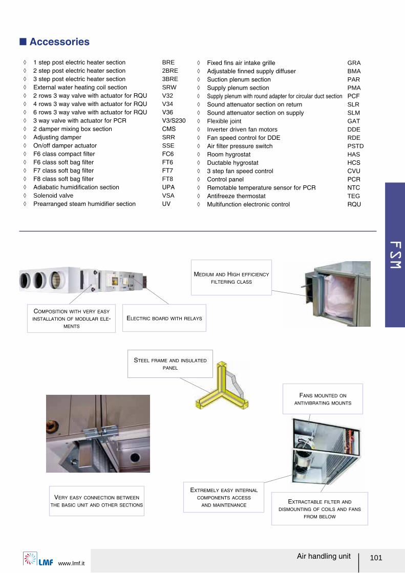
FSM
www.lmf.it101Air handling unit
Q Accessories
STEEL FRAME AND INSULATED
PANEL
ELECTRIC BOARD WITH RELAYS
FANS MOUNTED ON
ANTIVIBRATING MOUNTS
EXTREMELY EASY INTERNAL
COMPONENTS ACCESS
AND MAINTENANCEEXTRACTABLE FILTER AND
DISMOUNTING OF COILS AND FANS
FROM BELOW
COMPOSITION WITH VERY EASY
INSTALLATION OF MODULAR ELE-
MENTS
VERY EASY CONNECTION BETWEEN
THE BASIC UNIT AND OTHER SECTIONS
MEDIUM AND HIGH EFFICIENCY
FILTERING CLASS
ノ 1 step post electric heater section BRE ノ 2 step post electric heater section 2BRE ノ 3 step post electric heater section 3BRE ノ External water heating coil section SRW ノ 2 rows 3 way valve with actuator for RQU V32 ノ 4 rows 3 way valve with actuator for RQU V34 ノ 6 rows 3 way valve with actuator for RQU V36 ノ 3 way valve with actuator for PCR V3/S230 ノ 2 damper mixing box section CMS ノ Adjusting damper SRR ノ On/off damper actuator SSE ノ F6 class compact ルlter FC6 ノ F6 class soft bag ルlter FT6 ノ F7 class soft bag ルlter FT7 ノ F8 class soft bag ルlter FT8 ノ Adiabatic humidiルcation section UPA ノ Solenoid valve VSA ノ Prearranged steam humidiルer section UV
ノ Fixed ルns air intake grille GRA ノ Adjustable ルnned supply diffuser BMA ノ Suction plenum section PAR ノ Supply plenum section PMA ノ Supply plenum with round adapter for circular duct section PCF ノ Sound attenuator section on return SLR ノ Sound attenuator section on supply SLM ノ Flexible joint GAT ノ Inverter driven fan motors DDE ノ Fan speed control for DDE RDE ノ Air ルlter pressure switch PSTD ノ Room hygrostat HAS ノ Ductable hygrostat HCS ノ 3 step fan speed control CVU ノ Control panel PCR ノ Remotable temperature sensor for PCR NTC ノ Antifreeze thermostat TEG ノ Multifunction electronic control RQU
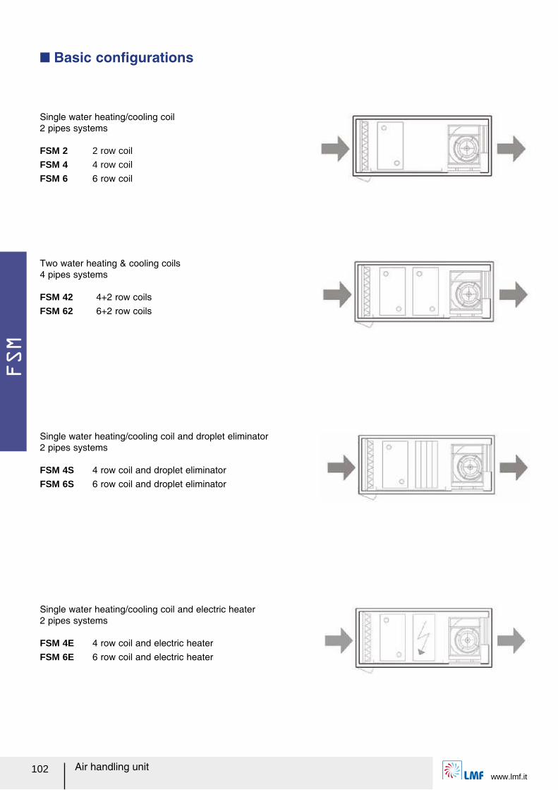
FSM
www.lmf.it102 Air handling unit
Single water heating/cooling coil 2 pipes systems
FSM 2 2 row coil
FSM 4 4 row coil
FSM 6 6 row coil
Two water heating & cooling coils 4 pipes systems
FSM 42 4+2 row coilsFSM 62 6+2 row coils
Single water heating/cooling coil and electric heater 2 pipes systems
FSM 4E 4 row coil and electric heaterFSM 6E 6 row coil and electric heater
Single water heating/cooling coil and droplet eliminator 2 pipes systems
FSM 4S 4 row coil and droplet eliminatorFSM 6S 6 row coil and droplet eliminator
Q Basic conルgurations
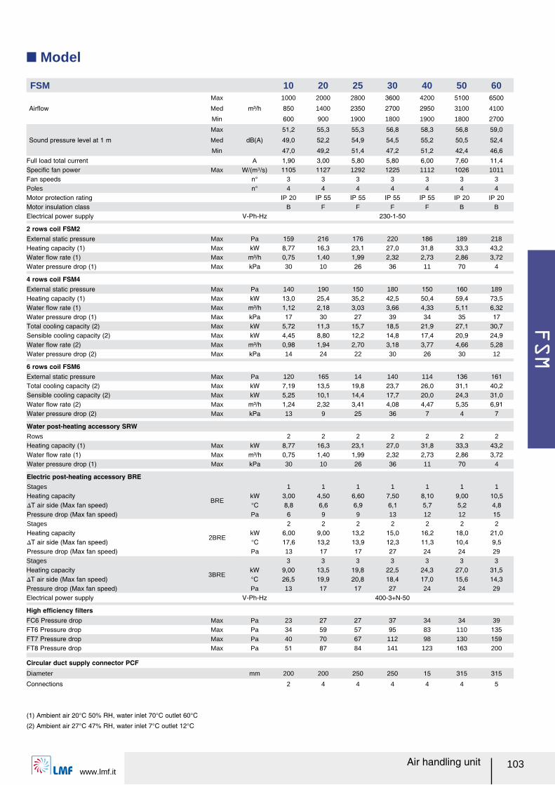
FSM
www.lmf.it103Air handling unit
Q Model
FSM 10 20 25 30 40 50 60
Airレow
Max
m³/h
1000 2000 2800 3600 4200 5100 6500
Med 850 1400 2350 2700 2950 3100 4100
Min 600 900 1900 1800 1900 1800 2700
Sound pressure level at 1 m
Max
dB(A)
51,2 55,3 55,3 56,8 58,3 56,8 59,0
Med 49,0 52,2 54,9 54,5 55,2 50,5 52,4
Min 47,0 49,2 51,4 47,2 51,2 42,4 46,6Full load total current A 1,90 3,00 5,80 5,80 6,00 7,60 11,4Speciルc fan power Max W/(m³/s) 1105 1127 1292 1225 1112 1026 1011Fan speeds n° 3 3 3 3 3 3 3Poles n° 4 4 4 4 4 4 4Motor protection rating IP 20 IP 55 IP 55 IP 55 IP 55 IP 20 IP 20Motor insulation class B F F F F B BElectrical power supply V-Ph-Hz 230-1-50
2 rows coil FSM2External static pressure Max Pa 159 216 176 220 186 189 218Heating capacity (1) Max kW 8,77 16,3 23,1 27,0 31,8 33,3 43,2Water レow rate (1) Max m³/h 0,75 1,40 1,99 2,32 2,73 2,86 3,72Water pressure drop (1) Max kPa 30 10 26 36 11 70 4
4 rows coil FSM4External static pressure Max Pa 140 190 150 180 150 160 189Heating capacity (1) Max kW 13,0 25,4 35,2 42,5 50,4 59,4 73,5Water レow rate (1) Max m³/h 1,12 2,18 3,03 3,66 4,33 5,11 6,32Water pressure drop (1) Max kPa 17 30 27 39 34 35 17Total cooling capacity (2) Max kW 5,72 11,3 15,7 18,5 21,9 27,1 30,7Sensible cooling capacity (2) Max kW 4,45 8,80 12,2 14,8 17,4 20,9 24,9Water レow rate (2) Max m³/h 0,98 1,94 2,70 3,18 3,77 4,66 5,28Water pressure drop (2) Max kPa 14 24 22 30 26 30 12
6 rows coil FSM6External static pressure Max Pa 120 165 14 140 114 136 161Total cooling capacity (2) Max kW 7,19 13,5 19,8 23,7 26,0 31,1 40,2Sensible cooling capacity (2) Max kW 5,25 10,1 14,4 17,7 20,0 24,3 31,0Water レow rate (2) Max m³/h 1,24 2,32 3,41 4,08 4,47 5,35 6,91Water pressure drop (2) Max kPa 13 9 25 36 7 4 7
Water post-heating accessory SRWRows 2 2 2 2 2 2 2Heating capacity (1) Max kW 8,77 16,3 23,1 27,0 31,8 33,3 43,2Water レow rate (1) Max m³/h 0,75 1,40 1,99 2,32 2,73 2,86 3,72Water pressure drop (1) Max kPa 30 10 26 36 11 70 4
Electric post-heating accessory BREStages
BRE
1 1 1 1 1 1 1Heating capacity kW 3,00 4,50 6,60 7,50 8,10 9,00 10,5スT air side (Max fan speed) °C 8,8 6,6 6,9 6,1 5,7 5,2 4,8Pressure drop (Max fan speed) Pa 6 9 9 13 12 12 15Stages
2BRE
2 2 2 2 2 2 2Heating capacity kW 6,00 9,00 13,2 15,0 16,2 18,0 21,0スT air side (Max fan speed) °C 17,6 13,2 13,9 12,3 11,3 10,4 9,5Pressure drop (Max fan speed) Pa 13 17 17 27 24 24 29Stages
3BRE
3 3 3 3 3 3 3Heating capacity kW 9,00 13,5 19,8 22,5 24,3 27,0 31,5スT air side (Max fan speed) °C 26,5 19,9 20,8 18,4 17,0 15,6 14,3Pressure drop (Max fan speed) Pa 13 17 17 27 24 24 29Electrical power supply V-Ph-Hz 400-3+N-50
High efルciency ルltersFC6 Pressure drop Max Pa 23 27 27 37 34 34 39FT6 Pressure drop Max Pa 34 59 57 95 83 110 135FT7 Pressure drop Max Pa 40 70 67 112 98 130 159FT8 Pressure drop Max Pa 51 87 84 141 123 163 200
Circular duct supply connector PCFDiameter mm 200 200 250 250 15 315 315
Connections 2 4 4 4 4 4 5
(1) Ambient air 20°C 50% RH, water inlet 70°C outlet 60°C
(2) Ambient air 27°C 47% RH, water inlet 7°C outlet 12°C

FSM
www.lmf.it104 Air handling unit
Q Max fan speed air performances
0
50
100
150
200
250
300
350
400
0 500 1000 1500 2000 2500 3000 3500 4000 4500 5000 5500 6000 6500 7000 7500
52,1
53,6
52,0
53,7
54,5
55,3
55,2
55,2
55,3
56,6
56,0
56,0
56,0
56,5
59,058,3
58,0
57,3
56,8
56,5
56,0
59,0
57,9
57,6
58,8
10
20
25
60
30 40
50
0
50
100
150
200
250
300
350
0 500 1000 1500 2000 2500 3000 3500 4000 4500 5000
50,0
49,0
52,6
52,2
52,2
54,9
54,9
55,6
54,0
54,6
54,5
55,4
55,0
55,3
43,1
50,5
54,8
52,4
1025
20
3040
50
60
0
50
100
150
200
250
300
0 500 1000 1500 2000 2500 3000 3500
42,4
51,2
48,3
47,2
49,2
52,0 51,4
50,6
43,7
49,2
47,0
1020
25
30
40
50
60
Airレow (m³/h)
Ext
erna
l Sta
tic P
ress
ure
(Pa)
Airレow (m³/h)
Ext
erna
l Sta
tic P
ress
ure
(Pa)
Airレow (m³/h)
Q Medium fan speed air performances
Q Minimum fan speed air performances
Ext
erna
l Sta
tic P
ress
ure
(Pa)
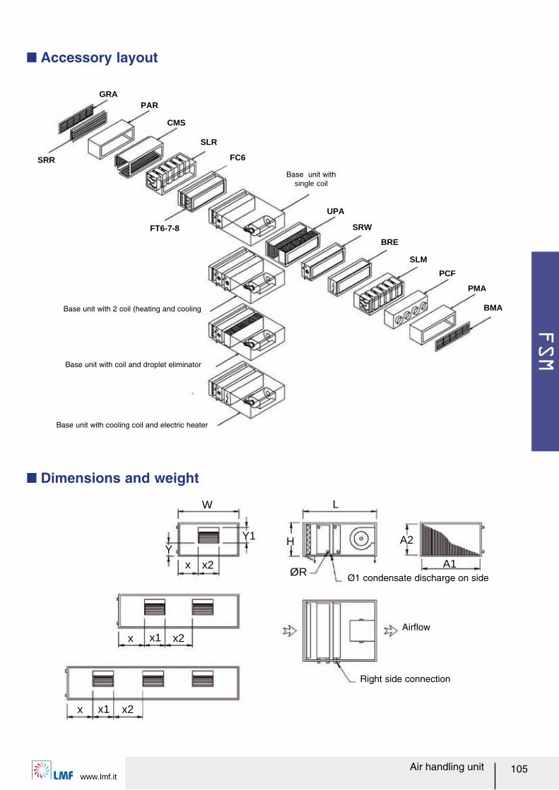
FSM
www.lmf.it105Air handling unit
Q Accessory layout
SRR
FT6-7-8
GRAPAR
CMS
SLR
UPA
SRW
BRE
SLM
PCF
PMA
BMA
FC6
Base unit with single coil
Base unit with 2 coil (heating and cooling
Base unit with coil and droplet eliminator
Base unit with cooling coil and electric heater
W L
A1
A2HY
Y1
ØRx2
x2x x1
x2x x1
xØ1 condensate discharge on side
Airレow
Right side connection
Q Dimensions and weight
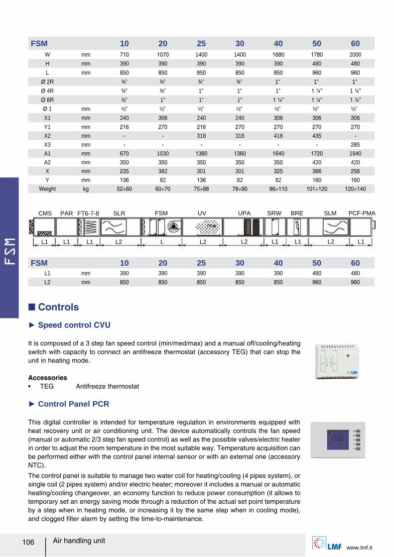
FSM
www.lmf.it106 Air handling unit
This digital controller is intended for temperature regulation in environments equipped with heat recovery unit or air conditioning unit. The device automatically controls the fan speed (manual or automatic 2/3 step fan speed control) as well as the possible valves/electric heater in order to adjust the room temperature in the most suitable way. Temperature acquisition can be performed either with the control panel internal sensor or with an external one (accessory NTC).
The control panel is suitable to manage two water coil for heating/cooling (4 pipes system), or single coil (2 pipes system) and/or electric heater; moreover it includes a manual or automatic heating/cooling changeover, an economy function to reduce power consumption (it allows to temporary set an energy saving mode through a reduction of the actual set point temperature by a step when in heating mode, or increasing it by the same step when in cooling mode), and clogged ルlter alarm by setting the time-to-maintenance.
Q Controls
Ź Speed control CVU
It is composed of a 3 step fan speed control (min/med/max) and a manual off/cooling/heating switch with capacity to connect an antifreeze thermostat (accessory TEG) that can stop the unit in heating mode.
Accessoriesー TEG Antifreeze thermostat
Ź Control Panel PCR
L1 L1 L2L1
FT6-7-8 SLRCMS PAR
L L2 L2 L1 L1 L2 L1
FSM UV UPA SRW BRE SLM PCF-PMA
FSM 10 20 25 30 40 50 60W mm 710 1070 1400 1400 1680 1780 2000
H mm 390 390 390 390 390 480 480
L mm 850 850 850 850 850 960 960Ø 2R ¾” ¾” ¾” ¾” 1” 1” 1”
Ø 4R ¾” ¾” 1” 1” 1” 1 ¼ャ 1 ¼ャØ 6R ¾” 1” 1” 1” 1 ¼ャ 1 ¼ャ 1 ¼ャØ 1 mm ½” ½” ½” ½” ½” ½” ½”
X1 mm 240 306 240 240 306 306 306Y1 mm 216 270 216 270 270 270 270X2 mm - - 318 318 418 435 -X3 mm - - - - - - 285A1 mm 670 1030 1360 1360 1640 1720 1940
A2 mm 350 350 350 350 350 420 420
X mm 235 382 301 301 325 366 256Y mm 136 82 136 82 82 160 160
Weight kg 52÷60 60÷70 75÷88 78÷90 96÷110 101÷120 120÷140
FSM 10 20 25 30 40 50 60L1 mm 390 390 390 390 390 480 480
L2 mm 850 850 850 850 850 960 960
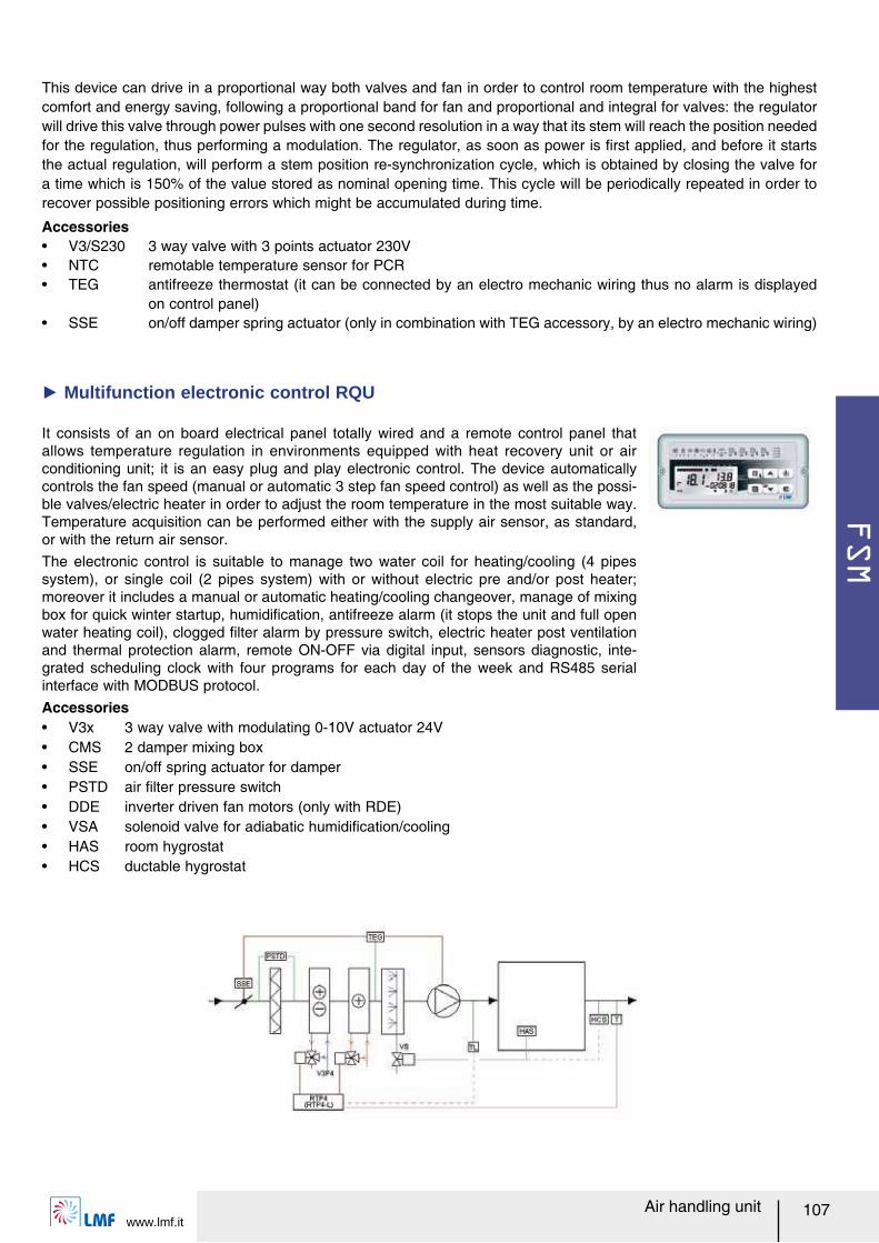
FSM
www.lmf.it107Air handling unit
It consists of an on board electrical panel totally wired and a remote control panel that allows temperature regulation in environments equipped with heat recovery unit or air conditioning unit; it is an easy plug and play electronic control. The device automatically controls the fan speed (manual or automatic 3 step fan speed control) as well as the possi-ble valves/electric heater in order to adjust the room temperature in the most suitable way. Temperature acquisition can be performed either with the supply air sensor, as standard, or with the return air sensor.The electronic control is suitable to manage two water coil for heating/cooling (4 pipes system), or single coil (2 pipes system) with or without electric pre and/or post heater; moreover it includes a manual or automatic heating/cooling changeover, manage of mixing box for quick winter startup, humidiルcation, antifreeze alarm (it stops the unit and full open water heating coil), clogged ルlter alarm by pressure switch, electric heater post ventilation and thermal protection alarm, remote ON-OFF via digital input, sensors diagnostic, inte-grated scheduling clock with four programs for each day of the week and RS485 serial interface with MODBUS protocol.
Ź Multifunction electronic control RQU
Accessoriesー V3x 3 way valve with modulating 0-10V actuator 24Vー CMS 2 damper mixing boxー SSE on/off spring actuator for damperー PSTD air ルlter pressure switchー DDE inverter driven fan motors (only with RDE)ー VSA solenoid valve for adiabatic humidiルcation/coolingー HAS room hygrostatー HCS ductable hygrostat
Accessoriesー V3/S230 3 way valve with 3 points actuator 230Vー NTC remotable temperature sensor for PCRー TEG antifreeze thermostat (it can be connected by an electro mechanic wiring thus no alarm is displayed
on control panel)ー SSE on/off damper spring actuator (only in combination with TEG accessory, by an electro mechanic wiring)
This device can drive in a proportional way both valves and fan in order to control room temperature with the highest comfort and energy saving, following a proportional band for fan and proportional and integral for valves: the regulator will drive this valve through power pulses with one second resolution in a way that its stem will reach the position needed for the regulation, thus performing a modulation. The regulator, as soon as power is ルrst applied, and before it starts the actual regulation, will perform a stem position re-synchronization cycle, which is obtained by closing the valve for a time which is 150% of the value stored as nominal opening time. This cycle will be periodically repeated in order to recover possible positioning errors which might be accumulated during time.
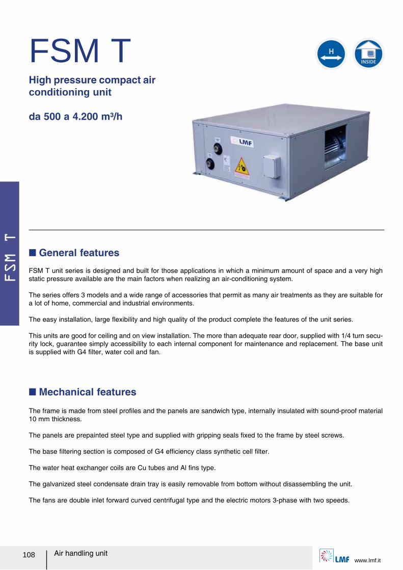
FSM T
www.lmf.it108 Air handling unit
FSM THigh pressure compact air conditioning unit da 500 a 4.200 m³/h
FSM T unit series is designed and built for those applications in which a minimum amount of space and a very high static pressure available are the main factors when realizing an air-conditioning system.
The series offers 3 models and a wide range of accessories that permit as many air treatments as they are suitable for a lot of home, commercial and industrial environments.
The easy installation, large レexibility and high quality of the product complete the features of the unit series.
This units are good for ceiling and on view installation. The more than adequate rear door, supplied with 1/4 turn secu-rity lock, guarantee simply accessibility to each internal component for maintenance and replacement. The base unit is supplied with G4 ルlter, water coil and fan.
Q General features
The frame is made from steel proルles and the panels are sandwich type, internally insulated with sound-proof material 10 mm thickness.
The panels are prepainted steel type and supplied with gripping seals ルxed to the frame by steel screws.
The base ルltering section is composed of G4 efルciency class synthetic cell ルlter.
The water heat exchanger coils are Cu tubes and Al ルns type.
The galvanized steel condensate drain tray is easily removable from bottom without disassembling the unit.
The fans are double inlet forward curved centrifugal type and the electric motors 3-phase with two speeds.
Q Mechanical features
INSIDE
H
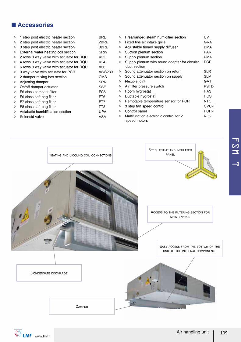
FSM T
www.lmf.it109Air handling unit
Q Accessories
ノ 1 step post electric heater section BRE ノ 2 step post electric heater section 2BRE ノ 3 step post electric heater section 3BRE ノ External water heating coil section SRW ノ 2 rows 3 way valve with actuator for RQU V32 ノ 4 rows 3 way valve with actuator for RQU V34 ノ 6 rows 3 way valve with actuator for RQU V36 ノ 3 way valve with actuator for PCR V3/S230 ノ 2 damper mixing box section CMS ノ Adjusting damper SRR ノ On/off damper actuator SSE ノ F6 class compact ルlter FC6 ノ F6 class soft bag ルlter FT6 ノ F7 class soft bag ルlter FT7 ノ F8 class soft bag ルlter FT8 ノ Adiabatic humidiルcation section UPA ノ Solenoid valve VSA
ノ Prearranged steam humidiルer section UV ノ Fixed ルns air intake grille GRA ノ Adjustable ルnned supply diffuser BMA ノ Suction plenum section PAR ノ Supply plenum section PMA ノ Supply plenum with round adapter for circular
duct sectionPCF
ノ Sound attenuator section on return SLR ノ Sound attenuator section on supply SLM ノ Flexible joint GAT ノ Air ルlter pressure switch PSTD ノ Room hygrostat HAS ノ Ductable hygrostat HCS ノ Remotable temperature sensor for PCR NTC ノ 3 step fan speed control CVU-T ノ Control panel PCR-T ノ Multifunction electronic control for 2
speed motorsRQ2
STEEL FRAME AND INSULATED
PANEL
EASY ACCESS FROM THE BOTTOM OF THE
UNIT TO THE INTERNAL COMPONENTS
DAMPER
CONDENSATE DISCHARGE
HEATING AND COOLING COIL CONNECTIONS
ACCESS TO THE FILTERING SECTION FOR
MAINTENANCE
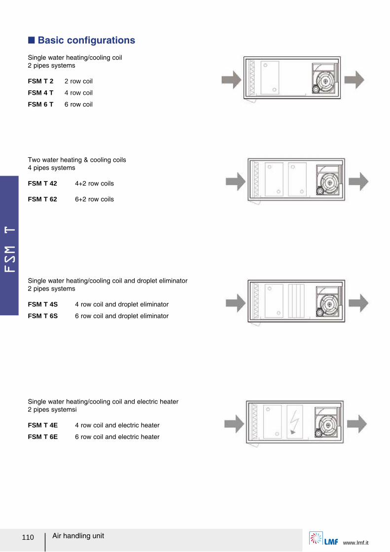
FSM T
www.lmf.it110 Air handling unit
Single water heating/cooling coil 2 pipes systems
FSM T 2 2 row coil
FSM 4 T 4 row coil
FSM 6 T 6 row coil
Two water heating & cooling coils 4 pipes systems
FSM T 42 4+2 row coils
FSM T 62 6+2 row coils
Single water heating/cooling coil and electric heater 2 pipes systemsi
FSM T 4E 4 row coil and electric heater
FSM T 6E 6 row coil and electric heater
Single water heating/cooling coil and droplet eliminator 2 pipes systems
FSM T 4S 4 row coil and droplet eliminator
FSM T 6S 6 row coil and droplet eliminator
Q Basic conルgurations
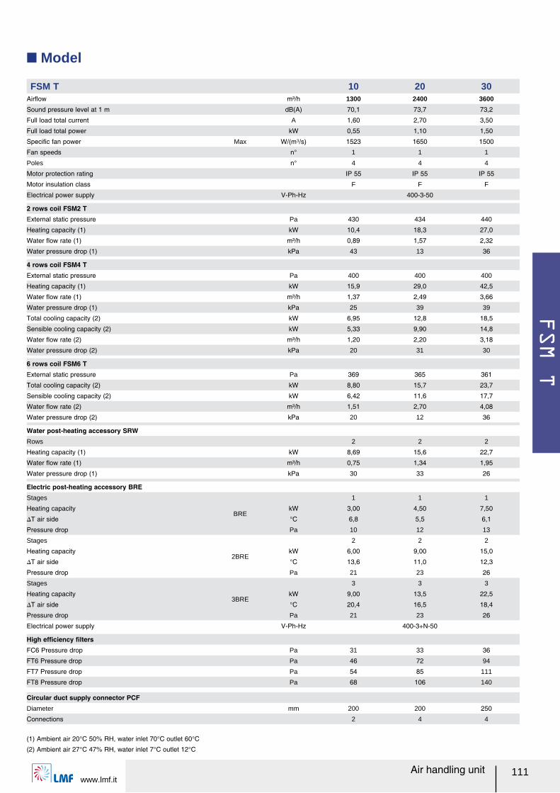
FSM T
www.lmf.it111Air handling unit
Q Model
FSM T 10 20 30Airレow m³/h 1300 2400 3600
Sound pressure level at 1 m dB(A) 70,1 73,7 73,2
Full load total current A 1,60 2,70 3,50
Full load total power kW 0,55 1,10 1,50
Speciルc fan power Max W/(m³/s) 1523 1650 1500
Fan speeds n° 1 1 1
Poles n° 4 4 4
Motor protection rating IP 55 IP 55 IP 55
Motor insulation class F F F
Electrical power supply V-Ph-Hz 400-3-50
2 rows coil FSM2 TExternal static pressure Pa 430 434 440
Heating capacity (1) kW 10,4 18,3 27,0
Water レow rate (1) m³/h 0,89 1,57 2,32
Water pressure drop (1) kPa 43 13 36
4 rows coil FSM4 TExternal static pressure Pa 400 400 400
Heating capacity (1) kW 15,9 29,0 42,5
Water レow rate (1) m³/h 1,37 2,49 3,66
Water pressure drop (1) kPa 25 39 39
Total cooling capacity (2) kW 6,95 12,8 18,5
Sensible cooling capacity (2) kW 5,33 9,90 14,8
Water レow rate (2) m³/h 1,20 2,20 3,18
Water pressure drop (2) kPa 20 31 30
6 rows coil FSM6 TExternal static pressure Pa 369 365 361
Total cooling capacity (2) kW 8,80 15,7 23,7
Sensible cooling capacity (2) kW 6,42 11,6 17,7
Water レow rate (2) m³/h 1,51 2,70 4,08
Water pressure drop (2) kPa 20 12 36
Water post-heating accessory SRWRows 2 2 2
Heating capacity (1) kW 8,69 15,6 22,7
Water レow rate (1) m³/h 0,75 1,34 1,95
Water pressure drop (1) kPa 30 33 26
Electric post-heating accessory BREStages
BRE
1 1 1
Heating capacity kW 3,00 4,50 7,50
スT air side °C 6,8 5,5 6,1
Pressure drop Pa 10 12 13
Stages
2BRE
2 2 2
Heating capacity kW 6,00 9,00 15,0
スT air side °C 13,6 11,0 12,3
Pressure drop Pa 21 23 26
Stages
3BRE
3 3 3
Heating capacity kW 9,00 13,5 22,5
スT air side °C 20,4 16,5 18,4
Pressure drop Pa 21 23 26
Electrical power supply V-Ph-Hz 400-3+N-50
High efルciency ルltersFC6 Pressure drop Pa 31 33 36
FT6 Pressure drop Pa 46 72 94
FT7 Pressure drop Pa 54 85 111
FT8 Pressure drop Pa 68 106 140
Circular duct supply connector PCFDiameter mm 200 200 250
Connections 2 4 4
(1) Ambient air 20°C 50% RH, water inlet 70°C outlet 60°C
(2) Ambient air 27°C 47% RH, water inlet 7°C outlet 12°C
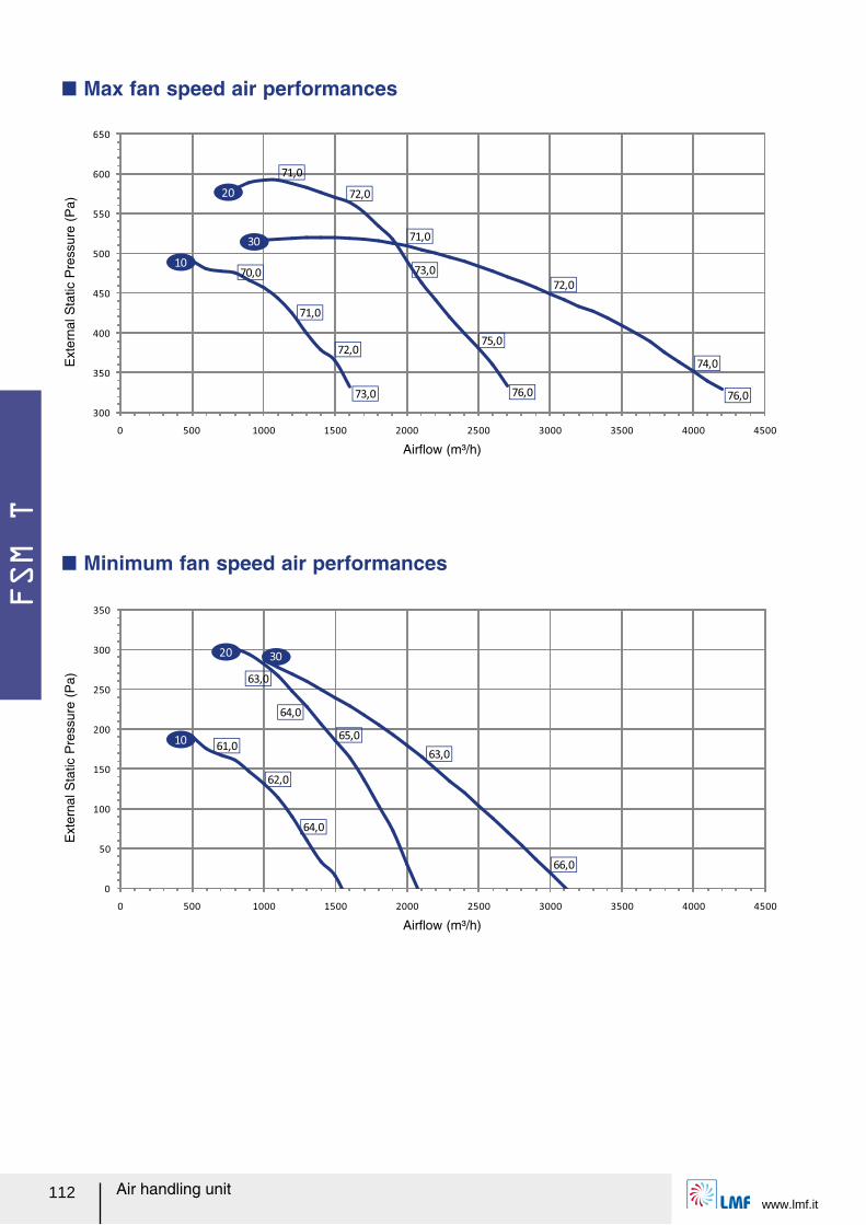
FSM T
www.lmf.it112 Air handling unit
Q Max fan speed air performances
300
350
400
450
500
550
600
650
0 500 1000 1500 2000 2500 3000 3500 4000 4500
70,0
71,0
72,0
73,0
71,0
72,0
73,0
75,0
76,0
71,0
72,0
74,0
76,0
10
20
30
0
50
100
150
200
250
300
350
0 500 1000 1500 2000 2500 3000 3500 4000 4500
61,0
62,0
64,0
63,0
63,0
64,0
65,0
66,0
10
20 30
Airレow (m³/h)
Ext
erna
l Sta
tic P
ress
ure
(Pa)
Airレow (m³/h)
Q Minimum fan speed air performances
Ext
erna
l Sta
tic P
ress
ure
(Pa)
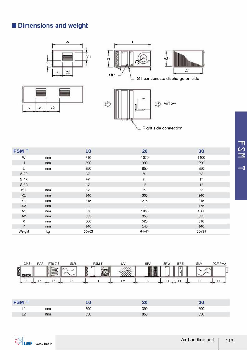
FSM T
www.lmf.it113Air handling unit
W L
A1
A2HY
Y1
ØRx2
x2x x1
x
Q Dimensions and weight
Ø1 condensate discharge on side
Airレow
Right side connection
L1 L1 L2 L L2 L2 L1 L1 L2 L1L1
FT6-7-8 SLR FSM T UV UPA SRW BRE SLM PCF-PMACMS PAR
FSM T 10 20 30W mm 710 1070 1400
H mm 390 390 390
L mm 850 850 850Ø 2R ¾” ¾” ¾”
Ø 4R ¾” ¾” 1”
Ø 6R ¾” 1” 1”Ø 1 mm ½” ½” ½”
X1 mm 240 306 240
Y1 mm 215 215 215X2 mm - - 175A1 mm 675 1035 1365A2 mm 355 355 355X mm 360 520 518Y mm 140 140 140
Weight kg 55÷63 64÷74 83÷95
FSM T 10 20 30L1 mm 390 390 390
L2 mm 850 850 850
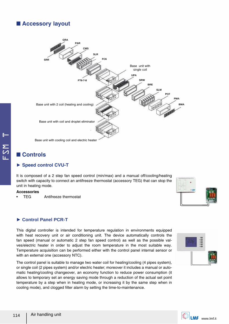
FSM T
www.lmf.it114 Air handling unit
This digital controller is intended for temperature regulation in environments equipped with heat recovery unit or air conditioning unit. The device automatically controls the fan speed (manual or automatic 2 step fan speed control) as well as the possible val-ves/electric heater in order to adjust the room temperature in the most suitable way. Temperature acquisition can be performed either with the control panel internal sensor or with an external one (accessory NTC).
The control panel is suitable to manage two water coil for heating/cooling (4 pipes system), or single coil (2 pipes system) and/or electric heater; moreover it includes a manual or auto-matic heating/cooling changeover, an economy function to reduce power consumption (it allows to temporary set an energy saving mode through a reduction of the actual set point temperature by a step when in heating mode, or increasing it by the same step when in cooling mode), and clogged ルlter alarm by setting the time-to-maintenance.
Q Controls
Ź Speed control CVU-T
It is composed of a 2 step fan speed control (min/max) and a manual off/cooling/heating switch with capacity to connect an antifreeze thermostat (accessory TEG) that can stop the unit in heating mode.
Accessoriesー TEG Antifreeze thermostat
Ź Control Panel PCR-T
Q Accessory layout
SRR
FT6-7-8
GRAPAR
CMS
SLR
UPA
SRW
BRE
SLM
PCF
PMA
BMA
FC6
Base unit with single coil
Base unit with 2 coil (heating and cooling)
Base unit with coil and droplet eliminator
Base unit with cooling coil and electric heater
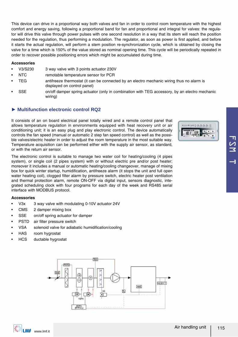
FSM T
www.lmf.it115Air handling unit
It consists of an on board electrical panel totally wired and a remote control panel that allows temperature regulation in environments equipped with heat recovery unit or air conditioning unit; it is an easy plug and play electronic control. The device automatically controls the fan speed (manual or automatic 2 step fan speed control) as well as the possi-ble valves/electric heater in order to adjust the room temperature in the most suitable way. Temperature acquisition can be performed either with the supply air sensor, as standard, or with the return air sensor.
The electronic control is suitable to manage two water coil for heating/cooling (4 pipes system), or single coil (2 pipes system) with or without electric pre and/or post heater; moreover it includes a manual or automatic heating/cooling changeover, manage of mixing box for quick winter startup, humidiルcation, antifreeze alarm (it stops the unit and full open water heating coil), clogged ルlter alarm by pressure switch, electric heater post ventilation and thermal protection alarm, remote ON-OFF via digital input, sensors diagnostic, inte-grated scheduling clock with four programs for each day of the week and RS485 serial interface with MODBUS protocol.
Ź Multifunction electronic control RQ2
Accessoriesー V3x 3 way valve with modulating 0-10V actuator 24Vー CMS 2 damper mixing boxー SSE on/off spring actuator for damperー PSTD air ルlter pressure switchー VSA solenoid valve for adiabatic humidiルcation/coolingー HAS room hygrostatー HCS ductable hygrostat
This device can drive in a proportional way both valves and fan in order to control room temperature with the highest comfort and energy saving, following a proportional band for fan and proportional and integral for valves: the regula-tor will drive this valve through power pulses with one second resolution in a way that its stem will reach the position needed for the regulation, thus performing a modulation. The regulator, as soon as power is ルrst applied, and before it starts the actual regulation, will perform a stem position re-synchronization cycle, which is obtained by closing the valve for a time which is 150% of the value stored as nominal opening time. This cycle will be periodically repeated in order to recover possible positioning errors which might be accumulated during time.
Accessoriesー V3/S230 3 way valve with 3 points actuator 230Vー NTC remotable temperature sensor for PCRー TEG antifreeze thermostat (it can be connected by an electro mechanic wiring thus no alarm is
displayed on control panel)ー SSE on/off damper spring actuator (only in combination with TEG accessory, by an electro mechanic
wiring)
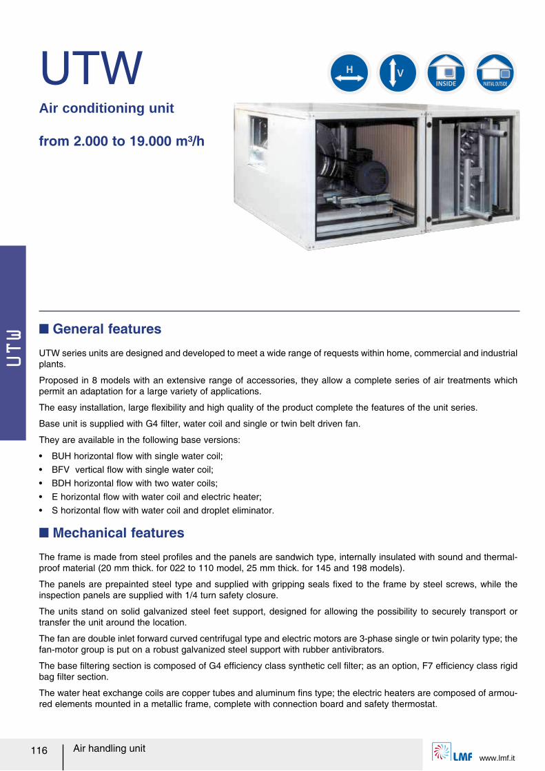
UTW
www.lmf.it116 Air handling unit
UTWAir conditioning unit
from 2.000 to 19.000 m³/h
UTW series units are designed and developed to meet a wide range of requests within home, commercial and industrial plants.
Proposed in 8 models with an extensive range of accessories, they allow a complete series of air treatments which permit an adaptation for a large variety of applications.
The easy installation, large レexibility and high quality of the product complete the features of the unit series.
Base unit is supplied with G4 ルlter, water coil and single or twin belt driven fan.
They are available in the following base versions:
ー BUH horizontal レow with single water coil;ー BFV vertical レow with single water coil;ー BDH horizontal レow with two water coils;ー E horizontal レow with water coil and electric heater;ー S horizontal レow with water coil and droplet eliminator.
Q General features
The frame is made from steel proルles and the panels are sandwich type, internally insulated with sound and thermal-proof material (20 mm thick. for 022 to 110 model, 25 mm thick. for 145 and 198 models).
The panels are prepainted steel type and supplied with gripping seals ルxed to the frame by steel screws, while the inspection panels are supplied with 1/4 turn safety closure.
The units stand on solid galvanized steel feet support, designed for allowing the possibility to securely transport or transfer the unit around the location.
The fan are double inlet forward curved centrifugal type and electric motors are 3-phase single or twin polarity type; the fan-motor group is put on a robust galvanized steel support with rubber antivibrators.
The base ルltering section is composed of G4 efルciency class synthetic cell ルlter; as an option, F7 efルciency class rigid bag ルlter section.
The water heat exchange coils are copper tubes and aluminum ルns type; the electric heaters are composed of armou-red elements mounted in a metallic frame, complete with connection board and safety thermostat.
Q Mechanical features
INSIDE PARTIAL OUTSIDE
H
V
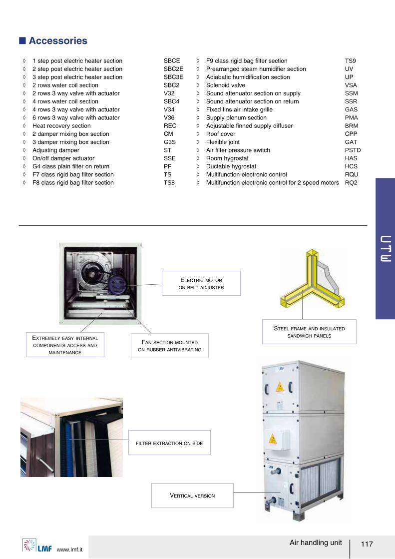
UTW
www.lmf.it117Air handling unit
Q Accessories
FILTER EXTRACTION ON SIDE
STEEL FRAME AND INSULATED
SANDWICH PANELSEXTREMELY EASY INTERNAL
COMPONENTS ACCESS AND
MAINTENANCE
FAN SECTION MOUNTED
ON RUBBER ANTIVIBRATING
ELECTRIC MOTOR
ON BELT ADJUSTER
ノ 1 step post electric heater section SBCE ノ 2 step post electric heater section SBC2E ノ 3 step post electric heater section SBC3E ノ 2 rows water coil section SBC2 ノ 2 rows 3 way valve with actuator V32 ノ 4 rows water coil section SBC4 ノ 4 rows 3 way valve with actuator V34 ノ 6 rows 3 way valve with actuator V36 ノ Heat recovery section REC ノ 2 damper mixing box section CM ノ 3 damper mixing box section G3S ノ Adjusting damper ST ノ On/off damper actuator SSE ノ G4 class plain ルlter on return PF ノ F7 class rigid bag ルlter section TS ノ F8 class rigid bag ルlter section TS8
ノ F9 class rigid bag ルlter section TS9 ノ Prearranged steam humidiルer section UV ノ Adiabatic humidiルcation section UP ノ Solenoid valve VSA ノ Sound attenuator section on supply SSM ノ Sound attenuator section on return SSR ノ Fixed ルns air intake grille GAS ノ Supply plenum section PMA ノ Adjustable ルnned supply diffuser BRM ノ Roof cover CPP ノ Flexible joint GAT ノ Air ルlter pressure switch PSTD ノ Room hygrostat HAS ノ Ductable hygrostat HCS ノ Multifunction electronic control RQU ノ Multifunction electronic control for 2 speed motors RQ2
VERTICAL VERSION
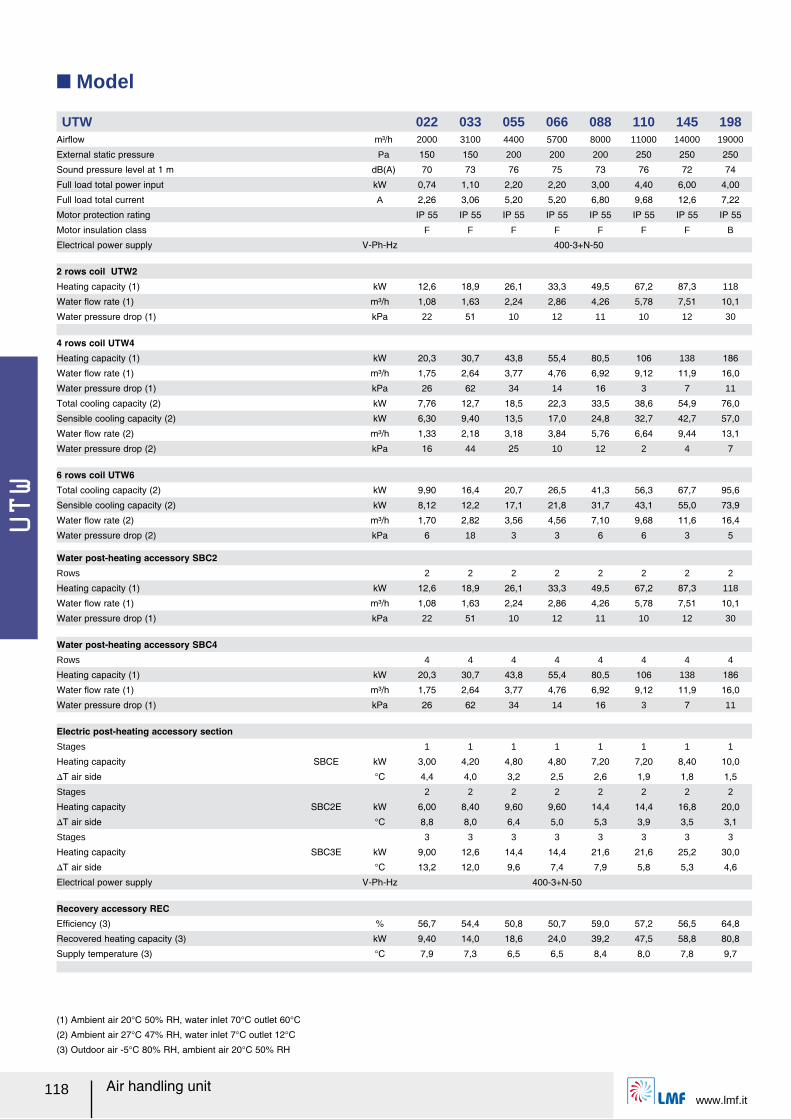
UTW
www.lmf.it118 Air handling unit
Q Model
UTW 022 033 055 066 088 110 145 198Airレow m³/h 2000 3100 4400 5700 8000 11000 14000 19000
External static pressure Pa 150 150 200 200 200 250 250 250
Sound pressure level at 1 m dB(A) 70 73 76 75 73 76 72 74
Full load total power input kW 0,74 1,10 2,20 2,20 3,00 4,40 6,00 4,00
Full load total current A 2,26 3,06 5,20 5,20 6,80 9,68 12,6 7,22
Motor protection rating IP 55 IP 55 IP 55 IP 55 IP 55 IP 55 IP 55 IP 55
Motor insulation class F F F F F F F B
Electrical power supply V-Ph-Hz 400-3+N-50
2 rows coil UTW2Heating capacity (1) kW 12,6 18,9 26,1 33,3 49,5 67,2 87,3 118
Water レow rate (1) m³/h 1,08 1,63 2,24 2,86 4,26 5,78 7,51 10,1
Water pressure drop (1) kPa 22 51 10 12 11 10 12 30
4 rows coil UTW4Heating capacity (1) kW 20,3 30,7 43,8 55,4 80,5 106 138 186
Water レow rate (1) m³/h 1,75 2,64 3,77 4,76 6,92 9,12 11,9 16,0
Water pressure drop (1) kPa 26 62 34 14 16 3 7 11
Total cooling capacity (2) kW 7,76 12,7 18,5 22,3 33,5 38,6 54,9 76,0
Sensible cooling capacity (2) kW 6,30 9,40 13,5 17,0 24,8 32,7 42,7 57,0
Water レow rate (2) m³/h 1,33 2,18 3,18 3,84 5,76 6,64 9,44 13,1
Water pressure drop (2) kPa 16 44 25 10 12 2 4 7
6 rows coil UTW6Total cooling capacity (2) kW 9,90 16,4 20,7 26,5 41,3 56,3 67,7 95,6
Sensible cooling capacity (2) kW 8,12 12,2 17,1 21,8 31,7 43,1 55,0 73,9
Water レow rate (2) m³/h 1,70 2,82 3,56 4,56 7,10 9,68 11,6 16,4
Water pressure drop (2) kPa 6 18 3 3 6 6 3 5
Water post-heating accessory SBC2Rows 2 2 2 2 2 2 2 2
Heating capacity (1) kW 12,6 18,9 26,1 33,3 49,5 67,2 87,3 118
Water レow rate (1) m³/h 1,08 1,63 2,24 2,86 4,26 5,78 7,51 10,1
Water pressure drop (1) kPa 22 51 10 12 11 10 12 30
Water post-heating accessory SBC4Rows 4 4 4 4 4 4 4 4
Heating capacity (1) kW 20,3 30,7 43,8 55,4 80,5 106 138 186
Water レow rate (1) m³/h 1,75 2,64 3,77 4,76 6,92 9,12 11,9 16,0
Water pressure drop (1) kPa 26 62 34 14 16 3 7 11
Electric post-heating accessory sectionStages
SBCE
1 1 1 1 1 1 1 1
Heating capacity kW 3,00 4,20 4,80 4,80 7,20 7,20 8,40 10,0
スT air side °C 4,4 4,0 3,2 2,5 2,6 1,9 1,8 1,5
Stages
SBC2E
2 2 2 2 2 2 2 2
Heating capacity kW 6,00 8,40 9,60 9,60 14,4 14,4 16,8 20,0
スT air side °C 8,8 8,0 6,4 5,0 5,3 3,9 3,5 3,1
Stages
SBC3E
3 3 3 3 3 3 3 3
Heating capacity kW 9,00 12,6 14,4 14,4 21,6 21,6 25,2 30,0
スT air side °C 13,2 12,0 9,6 7,4 7,9 5,8 5,3 4,6
Electrical power supply V-Ph-Hz 400-3+N-50
Recovery accessory RECEfルciency (3) % 56,7 54,4 50,8 50,7 59,0 57,2 56,5 64,8
Recovered heating capacity (3) kW 9,40 14,0 18,6 24,0 39,2 47,5 58,8 80,8
Supply temperature (3) °C 7,9 7,3 6,5 6,5 8,4 8,0 7,8 9,7
(1) Ambient air 20°C 50% RH, water inlet 70°C outlet 60°C
(2) Ambient air 27°C 47% RH, water inlet 7°C outlet 12°C
(3) Outdoor air -5°C 80% RH, ambient air 20°C 50% RH
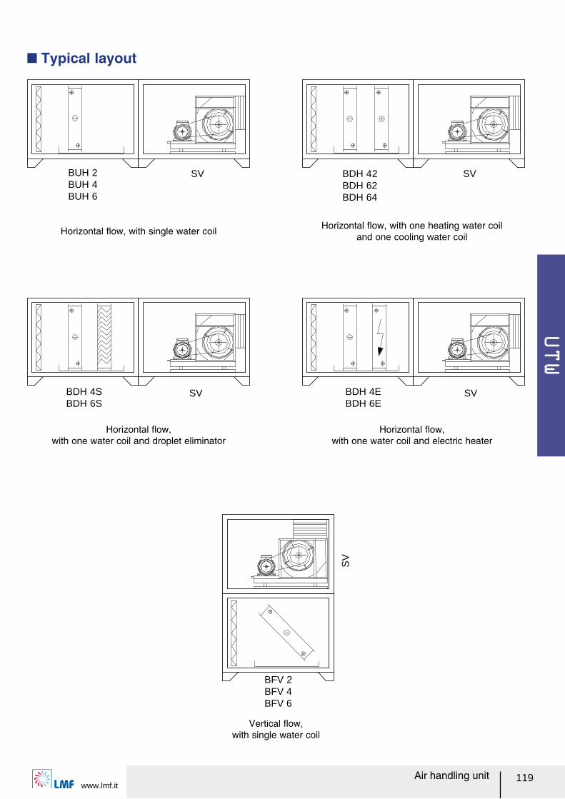
UTW
www.lmf.it119Air handling unit
Q Typical layout
BUH 2 SV SV
SV SV
SV
BUH 4BUH 6
BDH 42BDH 62BDH 64
BDH 4SBDH 6S
BDH 4EBDH 6E
BFV 2BFV 4BFV 6
Horizontal レow, with single water coil
Horizontal レow, with one water coil and droplet eliminator
Horizontal レow, with one water coil and electric heater
Horizontal レow, with one heating water coil and one cooling water coil
Vertical レow, with single water coil
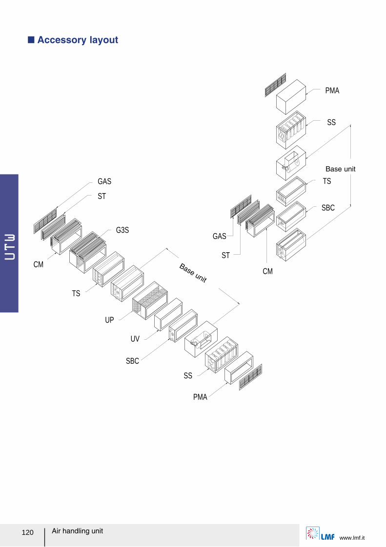
UTW
www.lmf.it120 Air handling unit
ST
G3S
CM
TS
UP
UV
SBC
SS
PMA
GAS
ST
CM
TS
SBC
SS
PMA
GAS
Base unit
Base unit
Q Accessory layout
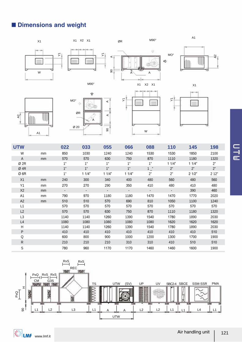
UTW
www.lmf.it121Air handling unit
X1
W
X1 X2 X1
X1 X2 X1
ØR M90°
M90°
A1
A
X1
A
W
A
A1
Ø 20
90A
Y1
Y1
A2Y
1
AA
A2
90
Y1 MO°
MO°
ØR
Ø 20
CM
L190H
L2 L3 L1
TS UTW (SV) UP UV SSM-SSR PMASBCESBC2-4
A A L2 L2 L1 L1 L1L4
UTW
G3S
REC
PxQ
PxQ
RxS
RxS RxS
RxS
Q Dimensions and weight
UTW 022 033 055 066 088 110 145 198W mm 850 1030 1240 1240 1530 1530 1850 2100
A mm 570 570 630 750 870 1110 1180 1320Ø 2R 1” 1” 1” 1” 1” 1 1/4ャ 1 1/4ャ 2”Ø 4R 1” 1” 1” 1” 1 _” 2” 2” 2”Ø 6R 1” 1 1/4ャ 1 1/4ャ 1 1/4ャ 2” 2” 2 1/2ャ 2 12”
X1 mm 240 300 340 400 480 560 480 560
Y1 mm 270 270 290 350 410 480 410 480X2 mm - - - - - - 390 460A1 mm 790 970 1180 1180 1470 1470 1770 2020
A2 mm 510 510 570 690 810 1050 1100 1240L1 570 570 570 570 570 570 570 570L2 570 570 630 750 870 1110 1180 1320
L3 1140 1140 1260 1390 1540 1780 1890 2030L4 1080 1080 1080 1080 1080 1620 1620 1620H 1140 1140 1260 1390 1540 1780 1890 2030P 410 410 410 410 410 410 410 510Q 600 800 900 1000 1200 1300 1700 1900
R 210 210 210 310 310 410 510 510
S 780 960 1170 1170 1460 1460 1600 1900
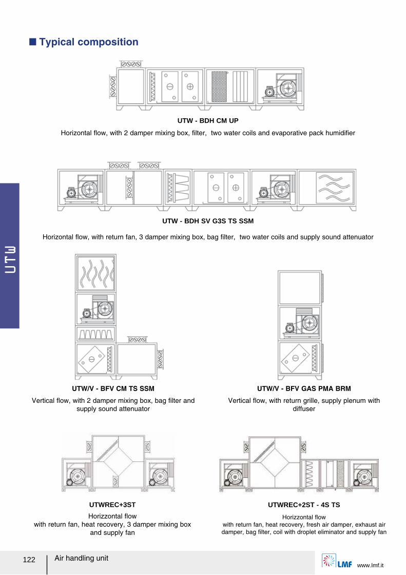
UTW
www.lmf.it122 Air handling unit
UTW - BDH CM UP
UTWREC+3ST UTWREC+2ST - 4S TS
Q Typical composition
UTW - BDH SV G3S TS SSM
UTW/V - BFV CM TS SSM UTW/V - BFV GAS PMA BRM
Horizontal レow, with 2 damper mixing box, ルlter, two water coils and evaporative pack humidiルer
Horizzontal レow with return fan, heat recovery, 3 damper mixing box
and supply fan
Horizzontal レow with return fan, heat recovery, fresh air damper, exhaust air damper, bag ルlter, coil with droplet eliminator and supply fan
Horizontal レow, with return fan, 3 damper mixing box, bag ルlter, two water coils and supply sound attenuator
Vertical レow, with 2 damper mixing box, bag ルlter and supply sound attenuator
Vertical レow, with return grille, supply plenum with diffuser
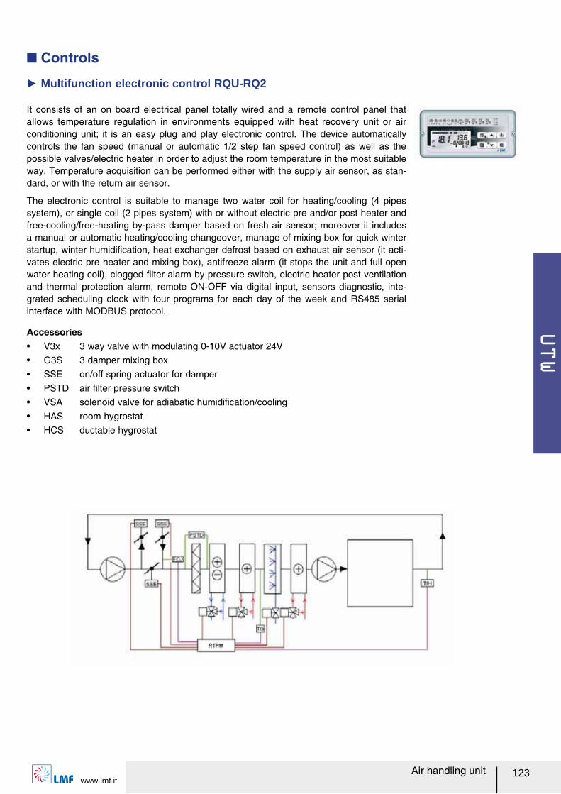
UTW
www.lmf.it123Air handling unit
Q Controls
It consists of an on board electrical panel totally wired and a remote control panel that allows temperature regulation in environments equipped with heat recovery unit or air conditioning unit; it is an easy plug and play electronic control. The device automatically controls the fan speed (manual or automatic 1/2 step fan speed control) as well as the possible valves/electric heater in order to adjust the room temperature in the most suitable way. Temperature acquisition can be performed either with the supply air sensor, as stan-dard, or with the return air sensor.
The electronic control is suitable to manage two water coil for heating/cooling (4 pipes system), or single coil (2 pipes system) with or without electric pre and/or post heater and free-cooling/free-heating by-pass damper based on fresh air sensor; moreover it includes a manual or automatic heating/cooling changeover, manage of mixing box for quick winter startup, winter humidiルcation, heat exchanger defrost based on exhaust air sensor (it acti-vates electric pre heater and mixing box), antifreeze alarm (it stops the unit and full open water heating coil), clogged ルlter alarm by pressure switch, electric heater post ventilation and thermal protection alarm, remote ON-OFF via digital input, sensors diagnostic, inte-grated scheduling clock with four programs for each day of the week and RS485 serial interface with MODBUS protocol.
Ź Multifunction electronic control RQU-RQ2
Accessoriesー V3x 3 way valve with modulating 0-10V actuator 24Vー G3S 3 damper mixing boxー SSE on/off spring actuator for damperー PSTD air ルlter pressure switchー VSA solenoid valve for adiabatic humidiルcation/coolingー HAS room hygrostatー HCS ductable hygrostat
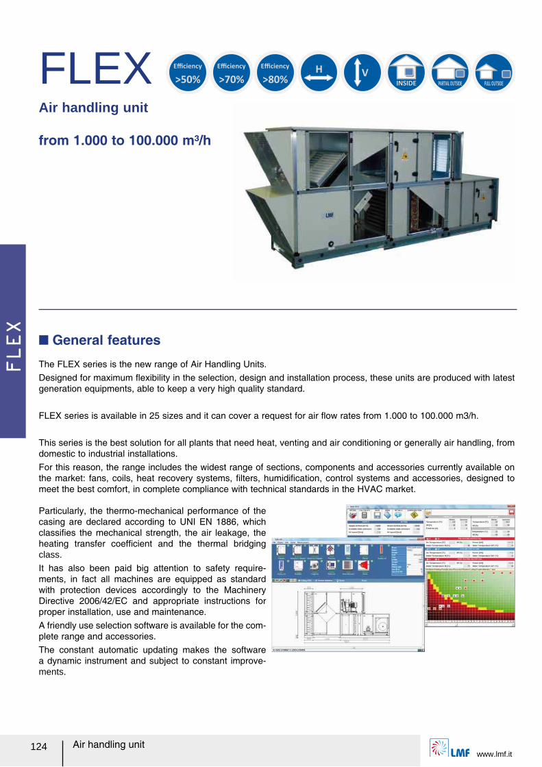
FLEX
www.lmf.it124 Air handling unit
FLEXAir handling unit from 1.000 to 100.000 m³/h
The FLEX series is the new range of Air Handling Units.Designed for maximum レexibility in the selection, design and installation process, these units are produced with latest generation equipments, able to keep a very high quality standard.
FLEX series is available in 25 sizes and it can cover a request for air レow rates from 1.000 to 100.000 m3/h.
This series is the best solution for all plants that need heat, venting and air conditioning or generally air handling, from domestic to industrial installations.For this reason, the range includes the widest range of sections, components and accessories currently available on the market: fans, coils, heat recovery systems, ルlters, humidiルcation, control systems and accessories, designed to meet the best comfort, in complete compliance with technical standards in the HVAC market.
Q General features
Particularly, the thermo-mechanical performance of the casing are declared according to UNI EN 1886, which classiルes the mechanical strength, the air leakage, the heating transfer coefルcient and the thermal bridging class.
It has also been paid big attention to safety require-ments, in fact all machines are equipped as standard with protection devices accordingly to the Machinery Directive 2006/42/EC and appropriate instructions for proper installation, use and maintenance.A friendly use selection software is available for the com-plete range and accessories.The constant automatic updating makes the software a dynamic instrument and subject to constant improve-ments.
H
V
INSIDE PARTIAL OUTSIDE
FULL OUTSIDE
>50%
Efficiency
>70%
Efficiency
>80%
Efficiency
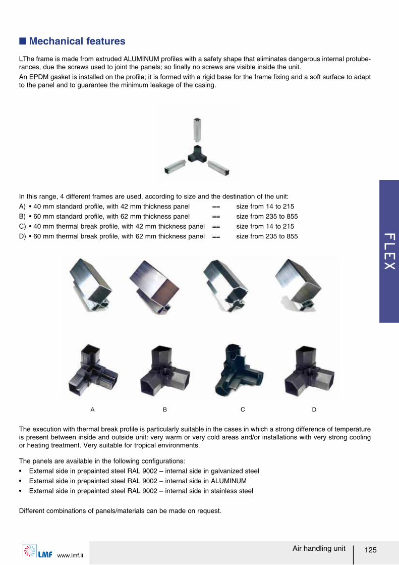
FLEX
www.lmf.it125Air handling unit
Q Mechanical features
LThe frame is made from extruded ALUMINUM proルles with a safety shape that eliminates dangerous internal protube-rances, due the screws used to joint the panels; so ルnally no screws are visible inside the unit.An EPDM gasket is installed on the proルle; it is formed with a rigid base for the frame ルxing and a soft surface to adapt to the panel and to guarantee the minimum leakage of the casing.
In this range, 4 different frames are used, according to size and the destination of the unit:A) ー 40 mm standard proルle, with 42 mm thickness panel == size from 14 to 215B) ー 60 mm standard proルle, with 62 mm thickness panel == size from 235 to 855C) ー 40 mm thermal break proルle, with 42 mm thickness panel == size from 14 to 215D) ー 60 mm thermal break proルle, with 62 mm thickness panel == size from 235 to 855
A B C D
The execution with thermal break proルle is particularly suitable in the cases in which a strong difference of temperature is present between inside and outside unit: very warm or very cold areas and/or installations with very strong cooling or heating treatment. Very suitable for tropical environments.
The panels are available in the following conルgurations:ー External side in prepainted steel RAL 9002 ヲ internal side in galvanized steelー External side in prepainted steel RAL 9002 ヲ internal side in ALUMINUMー External side in prepainted steel RAL 9002 ヲ internal side in stainless steel
Different combinations of panels/materials can be made on request.
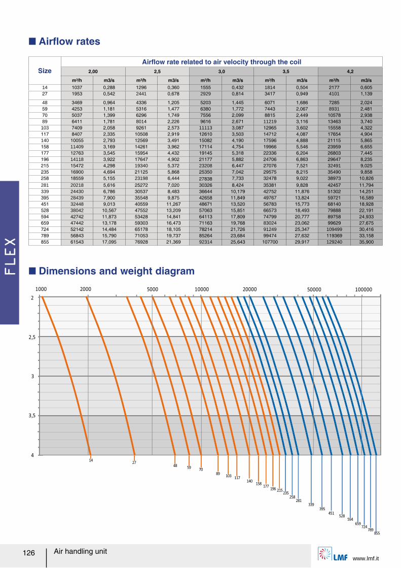
FLEX
www.lmf.it126 Air handling unit
1000 10000
4
3,5
3
2,5
2
2000 5000 10000020000 50000
1427
4859
7089
103117
140158
177196 215
235258
281339
395451
528594
659724
789855
Q Airレow rates
SizeAirレow rate related to air velocity through the coil
2,00 2,5 3,0 3,5 4,2
m³/h m3/s m³/h m3/s m³/h m3/s m³/h m3/s m³/h m3/s14 1037 0,288 1296 0,360 1555 0,432 1814 0,504 2177 0,60527 1953 0,542 2441 0,678 2929 0,814 3417 0,949 4101 1,139
48 3469 0,964 4336 1,205 5203 1,445 6071 1,686 7285 2,02459 4253 1,181 5316 1,477 6380 1,772 7443 2,067 8931 2,48170 5037 1,399 6296 1,749 7556 2,099 8815 2,449 10578 2,93889 6411 1,781 8014 2,226 9616 2,671 11219 3,116 13463 3,740103 7409 2,058 9261 2,573 11113 3,087 12965 3,602 15558 4,322117 8407 2,335 10508 2,919 12610 3,503 14712 4,087 17654 4,904140 10055 2,793 12569 3,491 15082 4,190 17596 4,888 21115 5,865158 11409 3,169 14261 3,962 17114 4,754 19966 5,546 23959 6,655177 12763 3,545 15954 4,432 19145 5,318 22336 6,204 26803 7,445196 14118 3,922 17647 4,902 21177 5,882 24706 6,863 29647 8,235215 15472 4,298 19340 5,372 23208 6,447 27076 7,521 32491 9,025235 16900 4,694 21125 5,868 25350 7,042 29575 8,215 35490 9,858258 18559 5,155 23198 6,444 27838 7,733 32478 9,022 38973 10,826281 20218 5,616 25272 7,020 30326 8,424 35381 9,828 42457 11,794339 24430 6,786 30537 8,483 36644 10,179 42752 11,876 51302 14,251395 28439 7,900 35548 9,875 42658 11,849 49767 13,824 59721 16,589451 32448 9,013 40559 11,267 48671 13,520 56783 15,773 68140 18,928528 38042 10,567 47552 13,209 57063 15,851 66573 18,493 79888 22,191594 42742 11,873 53428 14,841 64113 17,809 74799 20,777 89758 24,933659 47442 13,178 59303 16,473 71163 19,768 83024 23,062 99629 27,675724 52142 14,484 65178 18,105 78214 21,726 91249 25,347 109499 30,416789 56843 15,790 71053 19,737 85264 23,684 99474 27,632 119369 33,158855 61543 17,095 76928 21,369 92314 25,643 107700 29,917 129240 35,900
Q Dimensions and weight diagram
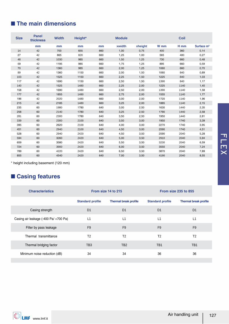
FLEX
www.lmf.it127Air handling unit
Q The main dimensions
Size Panel thickness Width Height* Module Coil
mm mm mm mm xwidth xheight W mm H mm Surface m²14 42 700 655 660 1,00 0,75 400 360 0,14
27 42 865 820 660 1,25 1,00 565 480 0,27
48 42 1030 985 660 1,50 1,25 730 660 0,48
59 42 1195 985 660 1,75 1,25 895 660 0,59
70 42 1360 985 660 2,00 1,25 1060 660 0,70
89 42 1360 1150 660 2,00 1,50 1060 840 0,89
103 42 1525 1150 660 2,25 1,50 1225 840 1,03
117 42 1690 1150 660 2,50 1,50 1390 840 1,17
140 42 1525 1480 660 2,25 2,00 1225 1140 1,40
158 42 1690 1480 660 2,50 2,00 1390 1140 1,58
177 42 1855 1480 660 2,75 2,00 1555 1140 1,77
196 42 2020 1480 660 3,00 2,00 1720 1140 1,96
215 42 2185 1480 660 3,25 2,00 1885 1140 2,15
235 60 1980 1780 640 3,00 2,50 1630 1440 2,35
258 60 2140 1780 640 3,25 2,50 1790 1440 2,58
281 60 2300 1780 640 3,50 2,50 1950 1440 2,81
339 60 2300 2100 640 3,50 3,00 1950 1740 3,39
395 60 2620 2100 640 4,00 3,00 2270 1740 3,95
451 60 2940 2100 640 4,50 3,00 2590 1740 4,51
528 60 2940 2420 640 4,50 3,50 2590 2040 5,28
594 60 3260 2420 640 5,00 3,50 2910 2040 5,94
659 60 3580 2420 640 5,50 3,50 3230 2040 6,59
724 60 3900 2420 640 6,00 3,50 3550 2040 7,24
789 60 4220 2420 640 6,50 3,50 3870 2040 7,89
855 60 4540 2420 640 7,00 3,50 4190 2040 8,55
* height including basement (120 mm)
Q Casing features
Characteristics From size 14 to 215 From size 235 to 855
Standard proルle Thermal break proルle Standard proルle Thermal break proルle
Casing strength D1 D1 D1 D1
Casing air leakage (-400 Pa/ +700 Pa) L1 L1 L1 L1
Filter by pass leakage F9 F9 F9 F9
Thermal transmittance T2 T2 T2 T2
Thermal bridging factor TB3 TB2 TB1 TB1
Minimum noise reduction (dB) 34 34 36 36
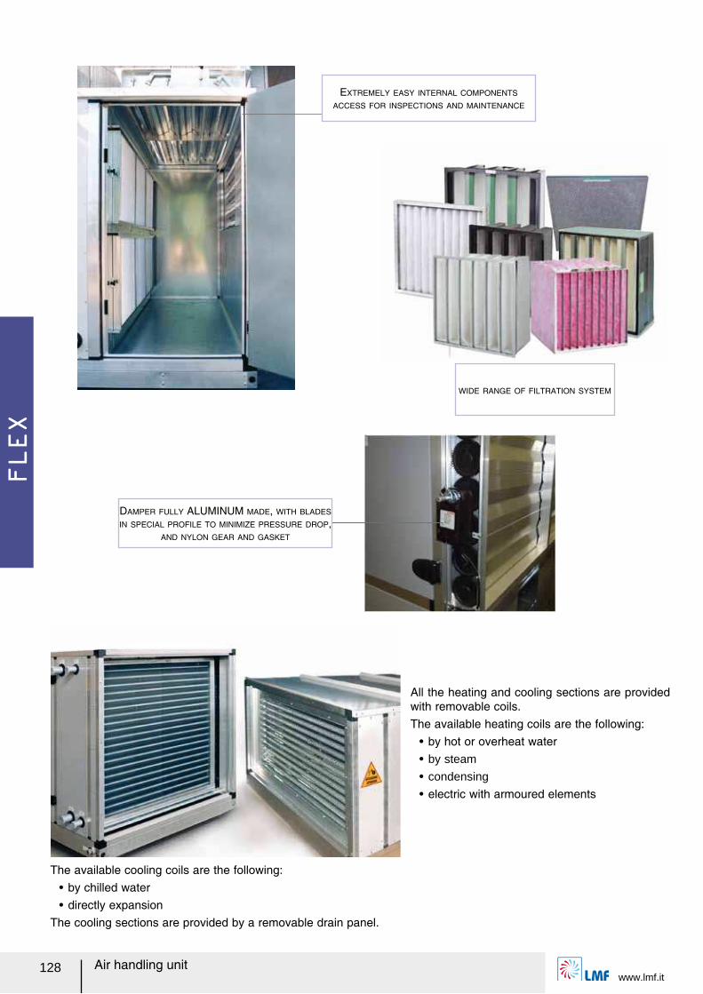
FLEX
www.lmf.it128 Air handling unit
EXTREMELY EASY INTERNAL COMPONENTS
ACCESS FOR INSPECTIONS AND MAINTENANCE
WIDE RANGE OF FILTRATION SYSTEM
All the heating and cooling sections are provided with removable coils.The available heating coils are the following:
ー by hot or overheat waterー by steam
ー condensing
ー electric with armoured elements
The available cooling coils are the following:ー by chilled waterー directly expansion
The cooling sections are provided by a removable drain panel.
DAMPER FULLY ALUMINUM MADE, WITH BLADES
IN SPECIAL PROFILE TO MINIMIZE PRESSURE DROP,
AND NYLON GEAR AND GASKET
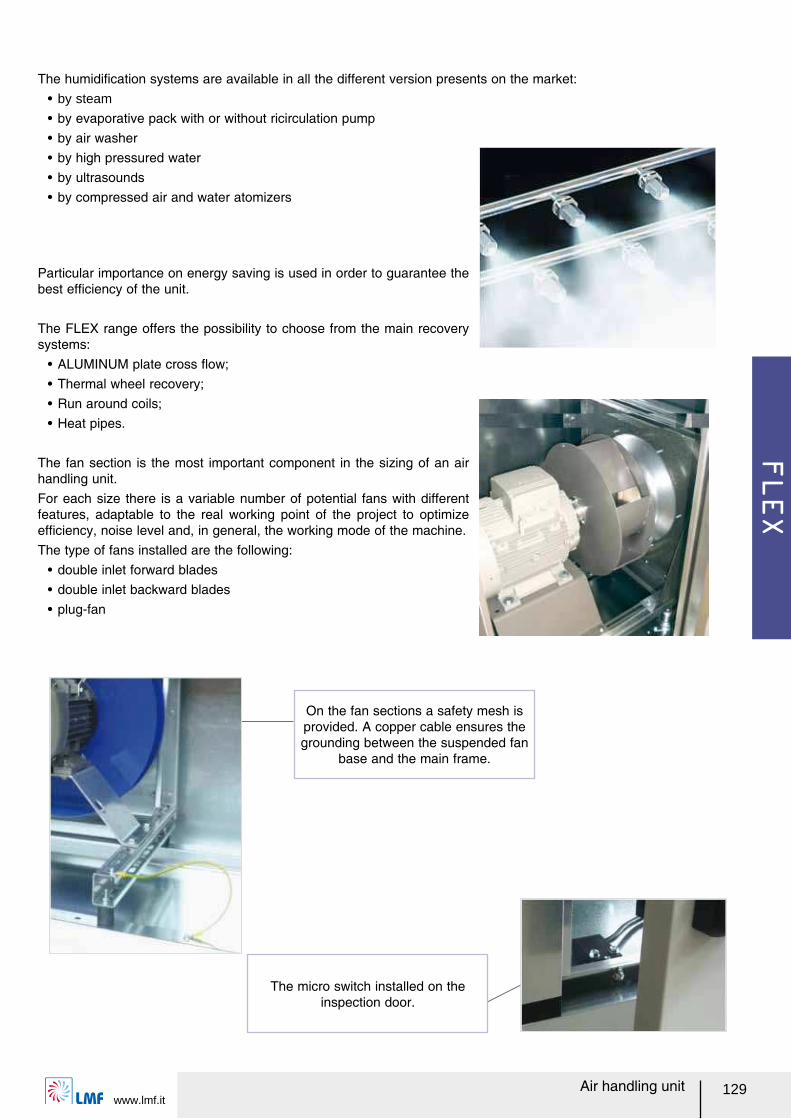
FLEX
www.lmf.it129Air handling unit
The humidiルcation systems are available in all the different version presents on the market:ー by steam
ー by evaporative pack with or without ricirculation pumpー by air washerー by high pressured waterー by ultrasoundsー by compressed air and water atomizers
Particular importance on energy saving is used in order to guarantee the best efルciency of the unit.
The FLEX range offers the possibility to choose from the main recovery systems:
ー ALUMINUM plate cross レow;ー Thermal wheel recovery;ー Run around coils;ー Heat pipes.
The fan section is the most important component in the sizing of an air handling unit.For each size there is a variable number of potential fans with different features, adaptable to the real working point of the project to optimize efルciency, noise level and, in general, the working mode of the machine.The type of fans installed are the following:
ー double inlet forward bladesー double inlet backward bladesー plug-fan
On the fan sections a safety mesh is provided. A copper cable ensures the grounding between the suspended fan
base and the main frame.
The micro switch installed on the inspection door.
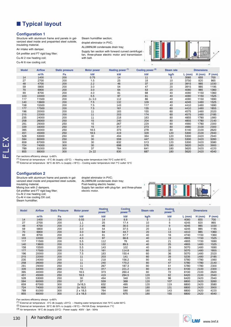
FLEX
www.lmf.it130 Air handling unit
Q Typical layout
Model Airレow Static pressure Motor power Heating power (1) Cooling power (2) Steam rate Dimensionsm³/h Pa kW kW kW kg/h L (mm) H (mm) P (mm)
14 1400 200 0.75 14 11 5 3585 655 70027 2700 200 1.5 25 18 10 3750 820 86548 4700 200 2.2 46 37 10 3915 985 103059 5800 200 3.0 54 47 20 3915 985 119570 6900 200 3.0 64 53 20 4080 985 136089 8700 200 4.0 81 68 40 4080 1150 1360
103 10000 200 5.5 97 81 40 4080 1150 1525117 11500 200 2x 3.0 112 86 40 4080 1150 1690140 13600 200 7.5 132 109 40 4245 1480 1525158 15500 200 7.5 143 117 40 4410 1480 1690177 17500 200 7.5 161 135 60 4410 1480 1855196 20000 200 11 183 155 60 4575 1480 2020215 22000 200 11 203 174 60 4575 1480 2185235 24000 200 11 218 183 80 4855 1780 1980258 26000 250 15 240 204 80 4855 1780 2140281 29000 250 15 267 229 80 4980 1780 2300339 34000 250 15 317 273 80 4980 2100 2300395 40000 250 18.5 373 278 80 5140 2100 2620451 45000 250 18.5 419 328 120 5300 2100 2940528 53000 250 30 494 384 120 5300 2420 2940594 60000 250 30 559 447 120 5300 2420 3260659 67000 300 30 632 513 120 5300 2420 3580724 74000 300 30 698 576 180 5620 2420 3900789 81000 300 37 764 641 180 5620 2420 4220855 88000 300 2x 22 830 687 180 5620 2420 4540
Structure with aluminum frame and panels in gal-vanized steel inside and prepainted steel outside, insulating material.
Air intake with damper.
G4 preルlter and F7 rigid bag ルlter;
Cu-Al 2 row heating coil;
Cu-Al 6 row cooling coil;
Steam humidiルer section;
droplet eliminator in PVC;
ALUMINUM condensate drain tray;
Supply fan section with forward curved centrifugal fan, three-phase electric motor and transmission with belt.
Conルguration 1
Fan sections efルciency always Ș>60%(1) External air temperature ヲ5°C db (supply >22°C) ヲ Heating water temperature inlet 70°C outlet 60°C.(2) External air temperature 32°C db 50% ru (supply <18°C) ヲ Cooling water temperature inlet 7°C outlet 12°C
Model Airレow Static Pressure Motor power Heatingpower (1)
Cooling power (2) Steam rate Heating
power (3) Dimensions
m³/h Pa kW kW kW kg/h kW L (mm) H (mm) P (mm)14 1400 200 0.55 14 8.8 5 3 4080 655 70027 2700 200 1.1 25 17.4 10 5 4245 820 86548 4700 200 2.2 46 30.5 10 9 4245 985 103059 5800 200 3.0 54 37.5 20 11 4245 985 119570 6900 200 3.0 64 44.7 20 13 4410 985 136089 8700 200 4.0 81 57.7 40 16 4740 1150 1360
103 10000 200 4.0 97 66.6 40 19 4905 1150 1525117 11500 200 5.5 112 76 40 21 4905 1150 1690140 13600 200 5.5 132 89.5 40 25 4905 1480 1525158 15500 200 5.5 143 102 40 29 5070 1480 1690177 17500 200 7.5 161 114.8 60 32 5070 1480 1855196 20000 200 7.5 183 150.4 60 36 5070 1480 2020215 22000 200 11 203 141 60 39 5235 1480 2185235 24000 200 11 218 156.2 80 43 5780 1780 1980258 26000 250 11 240 170.2 80 47 5780 1780 2140281 29000 250 11 267 187.3 80 51 5780 1780 2300339 34000 250 15 317 221.2 80 61 6100 2100 2300395 40000 250 18.5 373 260.4 80 72 6100 2100 2620451 45000 250 18.5 419 294.5 120 82 6420 2100 2940528 53000 250 30 494 348 120 96 6420 2420 2940594 60000 250 37 559 368 120 107 6800 2420 3260659 67000 300 2x18,5 632 495 120 119 6800 2420 3580724 74000 300 2x 18,5 698 544 180 131 6800 2420 3900789 81000 300 2 x 18,5 764 590 180 143 6800 2420 4220855 88000 300 2 x 18,5 830 675 180 155 6800 2420 4540
Structure with aluminum frame and panels in gal-vanized steel inside and prepainted steel outside, insulating material. Mixing box with 2 dampers. G4 preルlter and F7 rigid bag ルlter; Cu-Al 2 row heating coil;Cu-Al 4 row cooling DX coil;Steam humidiルer;
droplet eliminator in PVC; ALUMINUM condensate drain tray;Post-heating electric heater;Supply fan section with plug-fan and three-phase electric motor.
Conルguration 2
Fan sections efルciency always Ș>60%(1) External air temperature -5°C db (supply >23°C) ヲ Heating water temperature inlet 70°C outlet 60°C.(2) External air temperature 30°C db 50% ru (supply <18°C) ヲ R410A Evap. temperature 7°C(3) Air temperature 18°C db (supply 23°C) - Power supply 400V - 3ph - 50Hz
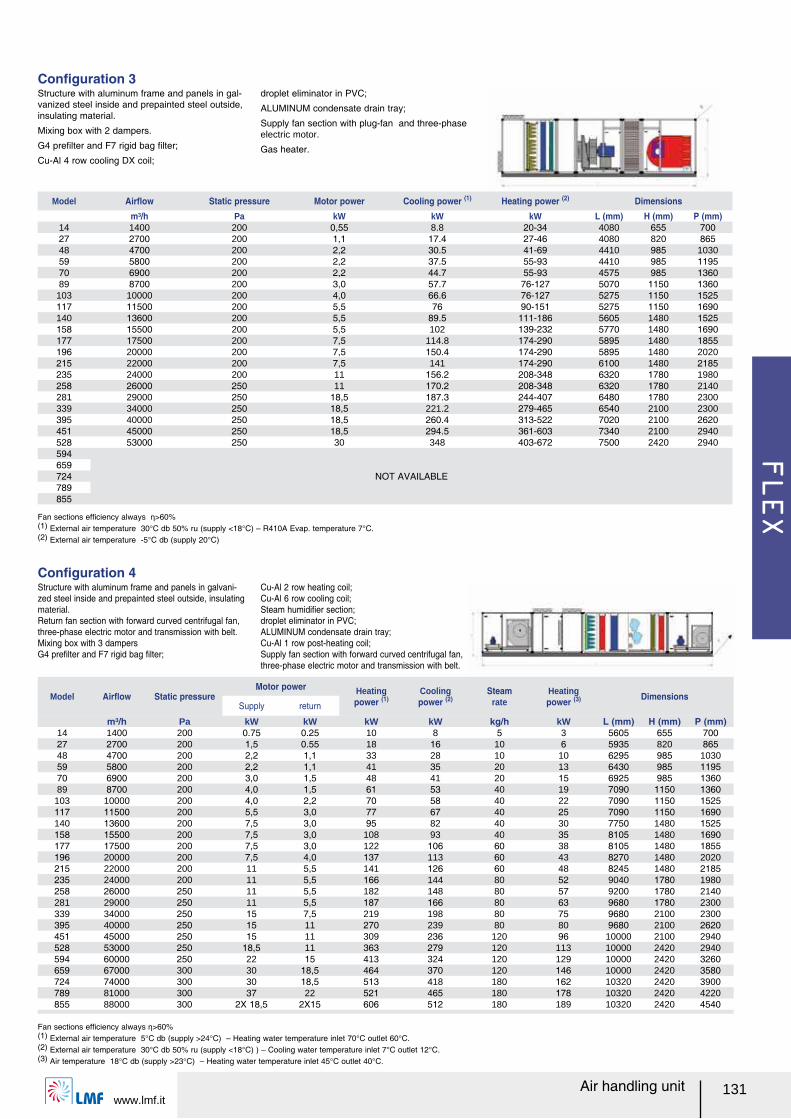
FLEX
www.lmf.it131Air handling unit
Structure with aluminum frame and panels in gal-vanized steel inside and prepainted steel outside, insulating material.
Mixing box with 2 dampers.
G4 preルlter and F7 rigid bag ルlter;
Cu-Al 4 row cooling DX coil;
droplet eliminator in PVC;
ALUMINUM condensate drain tray;
Supply fan section with plug-fan and three-phase electric motor.
Gas heater.
Conルguration 3
Fan sections efルciency always Ș>60%(1) External air temperature 30°C db 50% ru (supply <18°C) ヲ R410A Evap. temperature 7°C.(2) External air temperature -5°C db (supply 20°C)
Model Airレow Static pressureMotor power Heating
power (1)Cooling power (2)
Steam rate
Heatingpower (3) Dimensions
Supply return
m³/h Pa kW kW kW kW kg/h kW L (mm) H (mm) P (mm)14 1400 200 0.75 0.25 10 8 5 3 5605 655 70027 2700 200 1,5 0.55 18 16 10 6 5935 820 86548 4700 200 2,2 1,1 33 28 10 10 6295 985 103059 5800 200 2,2 1,1 41 35 20 13 6430 985 119570 6900 200 3,0 1,5 48 41 20 15 6925 985 136089 8700 200 4,0 1,5 61 53 40 19 7090 1150 1360
103 10000 200 4,0 2,2 70 58 40 22 7090 1150 1525117 11500 200 5,5 3,0 77 67 40 25 7090 1150 1690140 13600 200 7,5 3,0 95 82 40 30 7750 1480 1525158 15500 200 7,5 3,0 108 93 40 35 8105 1480 1690177 17500 200 7,5 3,0 122 106 60 38 8105 1480 1855196 20000 200 7,5 4,0 137 113 60 43 8270 1480 2020215 22000 200 11 5,5 141 126 60 48 8245 1480 2185235 24000 200 11 5,5 166 144 80 52 9040 1780 1980258 26000 250 11 5,5 182 148 80 57 9200 1780 2140281 29000 250 11 5,5 187 166 80 63 9680 1780 2300339 34000 250 15 7,5 219 198 80 75 9680 2100 2300395 40000 250 15 11 270 239 80 80 9680 2100 2620451 45000 250 15 11 309 236 120 96 10000 2100 2940528 53000 250 18,5 11 363 279 120 113 10000 2420 2940594 60000 250 22 15 413 324 120 129 10000 2420 3260659 67000 300 30 18,5 464 370 120 146 10000 2420 3580724 74000 300 30 18,5 513 418 180 162 10320 2420 3900789 81000 300 37 22 521 465 180 178 10320 2420 4220855 88000 300 2X 18,5 2X15 606 512 180 189 10320 2420 4540
Structure with aluminum frame and panels in galvani-zed steel inside and prepainted steel outside, insulating material. Return fan section with forward curved centrifugal fan, three-phase electric motor and transmission with belt.Mixing box with 3 dampersG4 preルlter and F7 rigid bag ルlter;
Cu-Al 2 row heating coil;Cu-Al 6 row cooling coil;Steam humidiルer section;droplet eliminator in PVC; ALUMINUM condensate drain tray;Cu-Al 1 row post-heating coil;Supply fan section with forward curved centrifugal fan, three-phase electric motor and transmission with belt.
Conルguration 4
Fan sections efルciency always Ș>60%(1) External air temperature 5°C db (supply >24°C) ヲ Heating water temperature inlet 70°C outlet 60°C.(2) External air temperature 30°C db 50% ru (supply <18°C) ) ヲ Cooling water temperature inlet 7°C outlet 12°C.(3) Air temperature 18°C db (supply >23°C) ヲ Heating water temperature inlet 45°C outlet 40°C.
Model Airレow Static pressure Motor power Cooling power (1) Heating power (2) Dimensionsm³/h Pa kW kW kW L (mm) H (mm) P (mm)
14 1400 200 0,55 8.8 20-34 4080 655 70027 2700 200 1,1 17.4 27-46 4080 820 86548 4700 200 2,2 30.5 41-69 4410 985 103059 5800 200 2,2 37.5 55-93 4410 985 119570 6900 200 2,2 44.7 55-93 4575 985 136089 8700 200 3,0 57.7 76-127 5070 1150 1360
103 10000 200 4,0 66.6 76-127 5275 1150 1525117 11500 200 5,5 76 90-151 5275 1150 1690140 13600 200 5,5 89.5 111-186 5605 1480 1525158 15500 200 5,5 102 139-232 5770 1480 1690177 17500 200 7,5 114.8 174-290 5895 1480 1855196 20000 200 7,5 150.4 174-290 5895 1480 2020215 22000 200 7,5 141 174-290 6100 1480 2185235 24000 200 11 156.2 208-348 6320 1780 1980258 26000 250 11 170.2 208-348 6320 1780 2140281 29000 250 18,5 187.3 244-407 6480 1780 2300339 34000 250 18,5 221.2 279-465 6540 2100 2300395 40000 250 18,5 260.4 313-522 7020 2100 2620451 45000 250 18,5 294.5 361-603 7340 2100 2940528 53000 250 30 348 403-672 7500 2420 2940594
NOT AVAILABLE659724789855
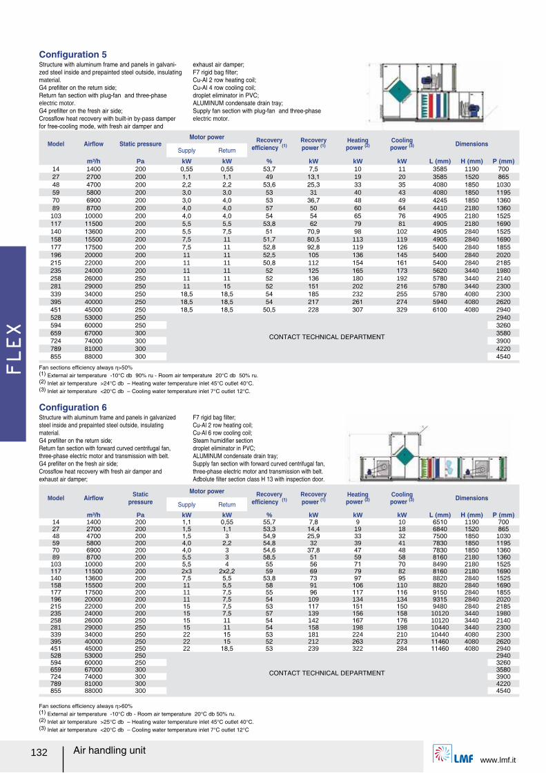
FLEX
www.lmf.it132 Air handling unit
Model Airレow Static pressureMotor power Recovery
efルciency (1)Recovery power (1)
Heating power (2)
Coolingpower (3) Dimensions
Supply Return
m³/h Pa kW kW % kW kW kW L (mm) H (mm) P (mm)14 1400 200 0,55 0,55 53,7 7,5 10 11 3585 1190 70027 2700 200 1,1 1,1 49 13,1 19 20 3585 1520 86548 4700 200 2,2 2,2 53,6 25,3 33 35 4080 1850 103059 5800 200 3,0 3,0 53 31 40 43 4080 1850 119570 6900 200 3,0 4,0 53 36,7 48 49 4245 1850 136089 8700 200 4,0 4,0 57 50 60 64 4410 2180 1360
103 10000 200 4,0 4,0 54 54 65 76 4905 2180 1525117 11500 200 5,5 5,5 53,8 62 79 81 4905 2180 1690140 13600 200 5,5 7,5 51 70,9 98 102 4905 2840 1525158 15500 200 7,5 11 51,7 80,5 113 119 4905 2840 1690177 17500 200 7,5 11 52,8 92,8 119 126 5400 2840 1855196 20000 200 11 11 52,5 105 136 145 5400 2840 2020215 22000 200 11 11 50,8 112 154 161 5400 2840 2185235 24000 200 11 11 52 125 165 173 5620 3440 1980258 26000 250 11 11 52 136 180 192 5780 3440 2140281 29000 250 11 15 52 151 202 216 5780 3440 2300339 34000 250 18,5 18,5 54 185 232 255 5780 4080 2300395 40000 250 18,5 18,5 54 217 261 274 5940 4080 2620451 45000 250 18,5 18,5 50,5 228 307 329 6100 4080 2940528 53000 250
CONTACT TECHNICAL DEPARTMENT
2940594 60000 250 3260659 67000 300 3580724 74000 300 3900789 81000 300 4220855 88000 300 4540
Structure with aluminum frame and panels in galvani-zed steel inside and prepainted steel outside, insulating material. G4 preルlter on the return side;Return fan section with plug-fan and three-phase electric motor.G4 preルlter on the fresh air side; Crossレow heat recovery with built-in by-pass damper for free-cooling mode, with fresh air damper and
exhaust air damper;F7 rigid bag ルlter;Cu-Al 2 row heating coil;Cu-Al 4 row cooling coil;droplet eliminator in PVC; ALUMINUM condensate drain tray;Supply fan section with plug-fan and three-phase electric motor.
Conルguration 5
Fan sections efルciency always Ș>50%(1) External air temperature -10°C db 90% ru - Room air temperature 20°C db 50% ru.(2) Inlet air temperature >24°C db ヲ Heating water temperature inlet 45°C outlet 40°C.(3) Inlet air temperature <20°C db ヲ Cooling water temperature inlet 7°C outlet 12°C.
Structure with aluminum frame and panels in galvanized steel inside and prepainted steel outside, insulating material. G4 preルlter on the return side;Return fan section with forward curved centrifugal fan, three-phase electric motor and transmission with belt.G4 preルlter on the fresh air side; Crossレow heat recovery with fresh air damper and exhaust air damper;
F7 rigid bag ルlter;Cu-Al 2 row heating coil;Cu-Al 6 row cooling coil;Steam humidiルer sectiondroplet eliminator in PVC; ALUMINUM condensate drain tray;Supply fan section with forward curved centrifugal fan, three-phase electric motor and transmission with belt.Adbolute ルlter section class H 13 with inspection door.
Conルguration 6
Fan sections efルciency always Ș>60%(1) External air temperature -10°C db - Room air temperature 20°C db 50% ru.(2) Inlet air temperature >25°C db ヲ Heating water temperature inlet 45°C outlet 40°C.(3) Inlet air temperature <20°C db ヲ Cooling water temperature inlet 7°C outlet 12°C
Model Airレow Static pressure
Motor power Recovery efルciency (1)
Recovery power (1)
Heating power (2)
Cooling power (3) Dimensions
Supply Return
m³/h Pa kW kW % kW kW kW L (mm) H (mm) P (mm)14 1400 200 1,1 0,55 55,7 7,8 9 10 6510 1190 70027 2700 200 1,5 1,1 53,3 14,4 19 18 6840 1520 86548 4700 200 1,5 3 54,9 25,9 33 32 7500 1850 103059 5800 200 4,0 2,2 54,8 32 39 41 7830 1850 119570 6900 200 4,0 3 54,6 37,8 47 48 7830 1850 136089 8700 200 5,5 3 58,5 51 59 58 8160 2180 1360
103 10000 200 5,5 4 55 56 71 70 8490 2180 1525117 11500 200 2x3 2x2,2 59 69 79 82 8160 2180 1690140 13600 200 7,5 5,5 53,8 73 97 95 8820 2840 1525158 15500 200 11 5,5 58 91 106 110 8820 2840 1690177 17500 200 11 7,5 55 96 117 116 9150 2840 1855196 20000 200 11 7,5 54 109 134 134 9315 2840 2020215 22000 200 15 7,5 53 117 151 150 9480 2840 2185235 24000 200 15 7,5 57 139 156 158 10120 3440 1980258 26000 250 15 11 54 142 167 176 10120 3440 2140281 29000 250 15 11 54 158 198 198 10440 3440 2300339 34000 250 22 15 53 181 224 210 10440 4080 2300395 40000 250 22 15 52 212 263 273 11460 4080 2620451 45000 250 22 18,5 53 239 322 284 11460 4080 2940528 53000 250
CONTACT TECHNICAL DEPARTMENT
2940594 60000 250 3260659 67000 300 3580724 74000 300 3900789 81000 300 4220855 88000 300 4540
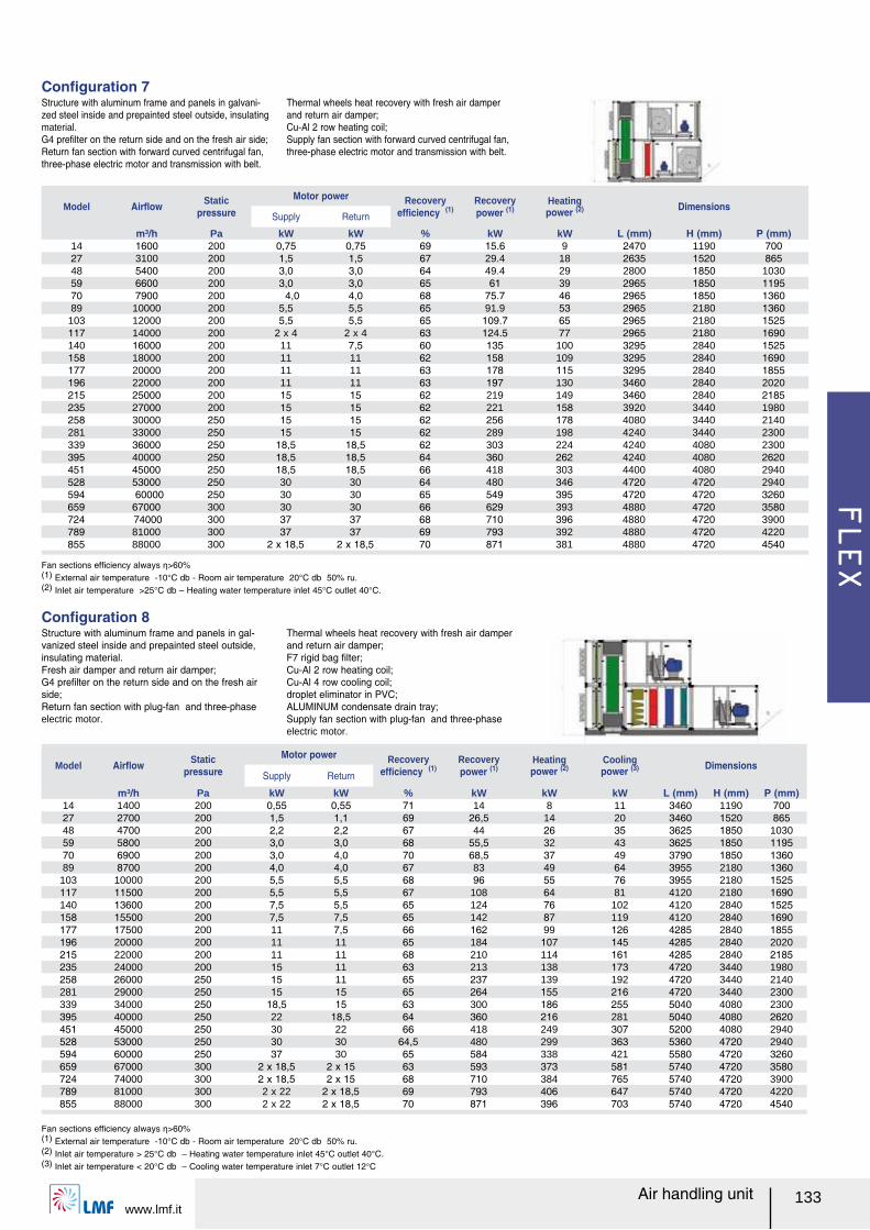
FLEX
www.lmf.it133Air handling unit
Structure with aluminum frame and panels in galvani-zed steel inside and prepainted steel outside, insulating material. G4 preルlter on the return side and on the fresh air side;Return fan section with forward curved centrifugal fan, three-phase electric motor and transmission with belt.
Thermal wheels heat recovery with fresh air damper and return air damper;Cu-Al 2 row heating coil;Supply fan section with forward curved centrifugal fan, three-phase electric motor and transmission with belt.
Conルguration 7
Fan sections efルciency always Ș>60%(1) External air temperature -10°C db - Room air temperature 20°C db 50% ru.(2) Inlet air temperature >25°C db ヲ Heating water temperature inlet 45°C outlet 40°C.
Model Airレow Static pressure
Motor power Recovery efルciency (1)
Recovery power (1)
Heating power (2) Dimensions
Supply Return
m³/h Pa kW kW % kW kW L (mm) H (mm) P (mm)14 1600 200 0,75 0,75 69 15.6 9 2470 1190 70027 3100 200 1,5 1,5 67 29.4 18 2635 1520 86548 5400 200 3,0 3,0 64 49.4 29 2800 1850 103059 6600 200 3,0 3,0 65 61 39 2965 1850 119570 7900 200 4,0 4,0 68 75.7 46 2965 1850 136089 10000 200 5,5 5,5 65 91.9 53 2965 2180 1360
103 12000 200 5,5 5,5 65 109.7 65 2965 2180 1525117 14000 200 2 x 4 2 x 4 63 124.5 77 2965 2180 1690140 16000 200 11 7,5 60 135 100 3295 2840 1525158 18000 200 11 11 62 158 109 3295 2840 1690177 20000 200 11 11 63 178 115 3295 2840 1855196 22000 200 11 11 63 197 130 3460 2840 2020215 25000 200 15 15 62 219 149 3460 2840 2185235 27000 200 15 15 62 221 158 3920 3440 1980258 30000 250 15 15 62 256 178 4080 3440 2140281 33000 250 15 15 62 289 198 4240 3440 2300339 36000 250 18,5 18,5 62 303 224 4240 4080 2300395 40000 250 18,5 18,5 64 360 262 4240 4080 2620451 45000 250 18,5 18,5 66 418 303 4400 4080 2940528 53000 250 30 30 64 480 346 4720 4720 2940594 60000 250 30 30 65 549 395 4720 4720 3260659 67000 300 30 30 66 629 393 4880 4720 3580724 74000 300 37 37 68 710 396 4880 4720 3900789 81000 300 37 37 69 793 392 4880 4720 4220855 88000 300 2 x 18,5 2 x 18,5 70 871 381 4880 4720 4540
Structure with aluminum frame and panels in gal-vanized steel inside and prepainted steel outside, insulating material. Fresh air damper and return air damper;G4 preルlter on the return side and on the fresh air side;Return fan section with plug-fan and three-phase electric motor.
Thermal wheels heat recovery with fresh air damper and return air damper;F7 rigid bag ルlter;Cu-Al 2 row heating coil;Cu-Al 4 row cooling coil;droplet eliminator in PVC; ALUMINUM condensate drain tray;Supply fan section with plug-fan and three-phase electric motor.
Conルguration 8
Fan sections efルciency always Ș>60%(1) External air temperature -10°C db - Room air temperature 20°C db 50% ru.(2) Inlet air temperature > 25°C db ヲ Heating water temperature inlet 45°C outlet 40°C.(3) Inlet air temperature < 20°C db ヲ Cooling water temperature inlet 7°C outlet 12°C
Model Airレow Static pressure
Motor power Recovery efルciency (1)
Recovery power (1)
Heating power (2)
Cooling power (3) Dimensions
Supply Return
m³/h Pa kW kW % kW kW kW L (mm) H (mm) P (mm)14 1400 200 0,55 0,55 71 14 8 11 3460 1190 70027 2700 200 1,5 1,1 69 26,5 14 20 3460 1520 86548 4700 200 2,2 2,2 67 44 26 35 3625 1850 103059 5800 200 3,0 3,0 68 55,5 32 43 3625 1850 119570 6900 200 3,0 4,0 70 68,5 37 49 3790 1850 136089 8700 200 4,0 4,0 67 83 49 64 3955 2180 1360
103 10000 200 5,5 5,5 68 96 55 76 3955 2180 1525117 11500 200 5,5 5,5 67 108 64 81 4120 2180 1690140 13600 200 7,5 5,5 65 124 76 102 4120 2840 1525158 15500 200 7,5 7,5 65 142 87 119 4120 2840 1690177 17500 200 11 7,5 66 162 99 126 4285 2840 1855196 20000 200 11 11 65 184 107 145 4285 2840 2020215 22000 200 11 11 68 210 114 161 4285 2840 2185235 24000 200 15 11 63 213 138 173 4720 3440 1980258 26000 250 15 11 65 237 139 192 4720 3440 2140281 29000 250 15 15 65 264 155 216 4720 3440 2300339 34000 250 18,5 15 63 300 186 255 5040 4080 2300395 40000 250 22 18,5 64 360 216 281 5040 4080 2620451 45000 250 30 22 66 418 249 307 5200 4080 2940528 53000 250 30 30 64,5 480 299 363 5360 4720 2940594 60000 250 37 30 65 584 338 421 5580 4720 3260659 67000 300 2 x 18,5 2 x 15 63 593 373 581 5740 4720 3580724 74000 300 2 x 18,5 2 x 15 68 710 384 765 5740 4720 3900789 81000 300 2 x 22 2 x 18,5 69 793 406 647 5740 4720 4220855 88000 300 2 x 22 2 x 18,5 70 871 396 703 5740 4720 4540
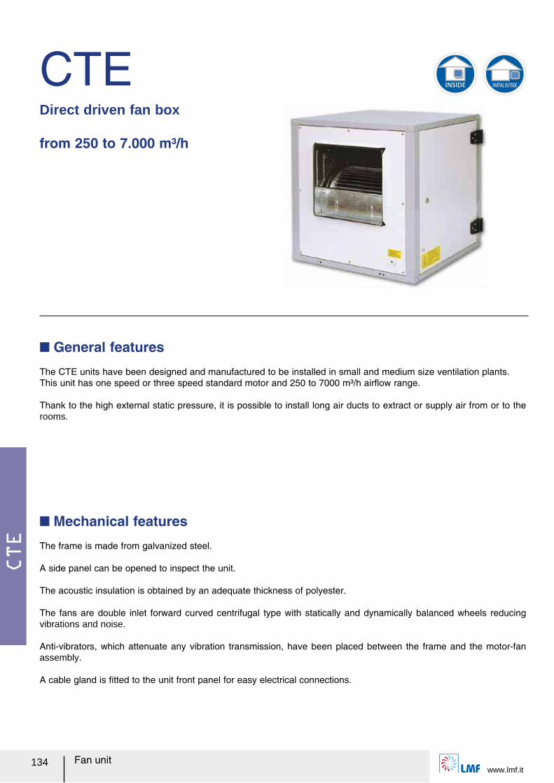
CTE
Fan unitwww.lmf.it
134
CTEDirect driven fan box
from 250 to 7.000 m³/h
The CTE units have been designed and manufactured to be installed in small and medium size ventilation plants.This unit has one speed or three speed standard motor and 250 to 7000 m³/h airレow range.
Thank to the high external static pressure, it is possible to install long air ducts to extract or supply air from or to the rooms.
Q General features
Q Mechanical features
The frame is made from galvanized steel.
A side panel can be opened to inspect the unit.
The acoustic insulation is obtained by an adequate thickness of polyester.
The fans are double inlet forward curved centrifugal type with statically and dynamically balanced wheels reducing vibrations and noise.
Anti-vibrators, which attenuate any vibration transmission, have been placed between the frame and the motor-fan assembly.
A cable gland is ルtted to the unit front panel for easy electrical connections.
INSIDE PARTIAL OUTSIDE
CTE
www.lmf.itFan unit 135
Q Accessories
CTE 1v 576 574 696 694 616 614 726 726T
Type fan 7/7 7/7 9/9 9/9 10/10 10/10 12/12 12/12
Shaft power W 62 147 147 300 254 373 736 1100
Max current A 1,00 1,80 2,10 3,50 2,65 4,80 7,60 7,80/4,50
Fan speeds 1 1 1 1 1 1 1 1
Poles 6 4 6 4 6 4 6 6
Protection degree IP 20 20 20 20 20 20 20 20
Temperature class B B B B B B B B
Electrical power supply V-ph-Hz 230-1-50 230/400-3-50
Q Model
CTE 3v 576V 574V 696V 694V 616V 614V 726V
Type fan 7/7 7/7 9/9 9/9 10/10 10/10 12/12
Shaft power W 147 147 245 420 245 420 736
Max current A 1,15 1,90 2,50 3,80 3,00 4,1 6,80
Fan speeds 3 3 3 3 3 3 3
Poles 6 4 6 4 6 4 6
Protection degree IP 32 20 20 20 20 20 20
Temperature class B B F B F B F
Electrical power supply V-ph-Hz 230-1-50
ノ Roof cover TP
ノ External hood CU ノ Overpressure damper SG
ノ Supports H=90 mm PD
ノ Single-phase electronic speed regulator RCS ノ 3 step fan speed control RCV ノ Auto transformer speed regulator VT
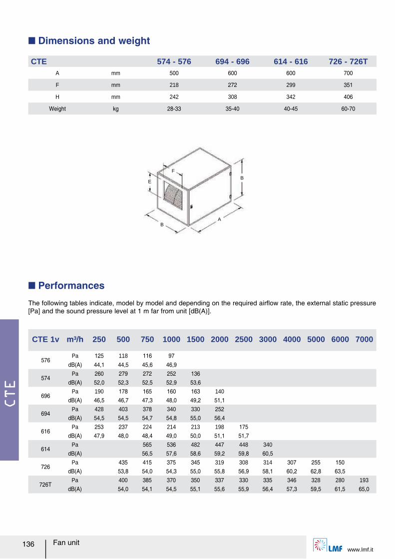
CTE
Fan unitwww.lmf.it
136
BA
BE
F
Q Dimensions and weight
CTE 574 - 576 694 - 696 614 - 616 726 - 726TA mm 500 600 600 700
F mm 218 272 299 351
H mm 242 308 342 406
Weight kg 28-33 35-40 40-45 60-70
CTE 1v m³/h 250 500 750 1000 1500 2000 2500 3000 4000 5000 6000 7000
576Pa 125 118 116 97
dB(A) 44,1 44,5 45,6 46,9
574Pa 260 279 272 252 136
dB(A) 52,0 52,3 52,5 52,9 53,6
696Pa 190 178 165 160 163 140
dB(A) 46,5 46,7 47,3 48,0 49,2 51,1
694Pa 428 403 378 340 330 252
dB(A) 54,5 54,5 54,7 54,8 55,0 56,4
616Pa 253 237 224 214 213 198 175
dB(A) 47,9 48,0 48,4 49,0 50,0 51,1 51,7
614Pa 565 536 482 447 448 340
dB(A) 56,5 57,6 58,6 59,2 59,8 60,5
726Pa 435 415 375 345 319 308 314 307 255 150
dB(A) 53,8 54,0 54,3 55,0 55,8 56,9 58,1 60,2 62,8 63,5
726TPa 400 385 370 350 337 330 335 346 328 280 193
dB(A) 54,0 54,1 54,5 55,1 55,6 55,9 56,4 57,3 59,5 61,5 65,0
Q Performances
The following tables indicate, model by model and depending on the required airレow rate, the external static pressure [Pa] and the sound pressure level at 1 m far from unit [dB(A)].
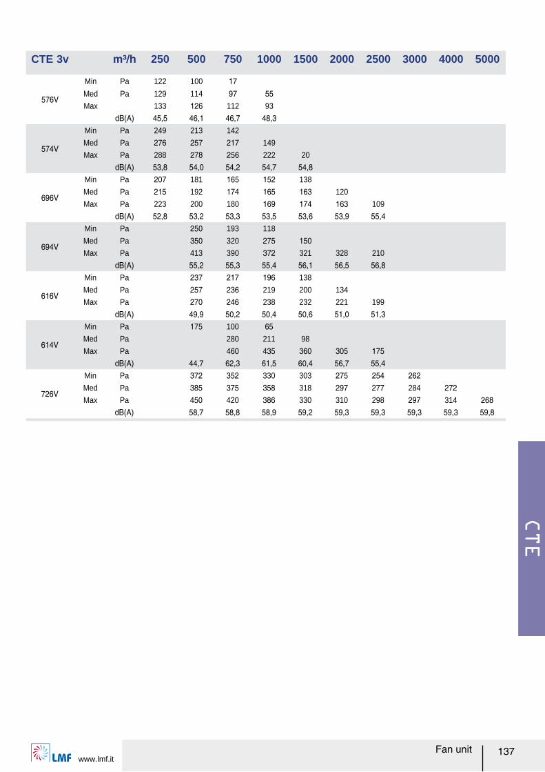
CTE
www.lmf.itFan unit 137
CTE 3v m³/h 250 500 750 1000 1500 2000 2500 3000 4000 5000
576V
Min Pa 122 100 17Med Pa 129 114 97 55Max 133 126 112 93
dB(A) 45,5 46,1 46,7 48,3
574V
Min Pa 249 213 142
Med Pa 276 257 217 149
Max Pa 288 278 256 222 20
dB(A) 53,8 54,0 54,2 54,7 54,8
696V
Min Pa 207 181 165 152 138
Med Pa 215 192 174 165 163 120
Max Pa 223 200 180 169 174 163 109
dB(A) 52,8 53,2 53,3 53,5 53,6 53,9 55,4
694V
Min Pa 250 193 118
Med Pa 350 320 275 150Max Pa 413 390 372 321 328 210
dB(A) 55,2 55,3 55,4 56,1 56,5 56,8
616V
Min Pa 237 217 196 138
Med Pa 257 236 219 200 134
Max Pa 270 246 238 232 221 199
dB(A) 49,9 50,2 50,4 50,6 51,0 51,3
614V
Min Pa 175 100 65Med Pa 280 211 98
Max Pa 460 435 360 305 175dB(A) 44,7 62,3 61,5 60,4 56,7 55,4
726V
Min Pa 372 352 330 303 275 254 262Med Pa 385 375 358 318 297 277 284 272Max Pa 450 420 386 330 310 298 297 314 268
dB(A) 58,7 58,8 58,9 59,2 59,3 59,3 59,3 59,3 59,8
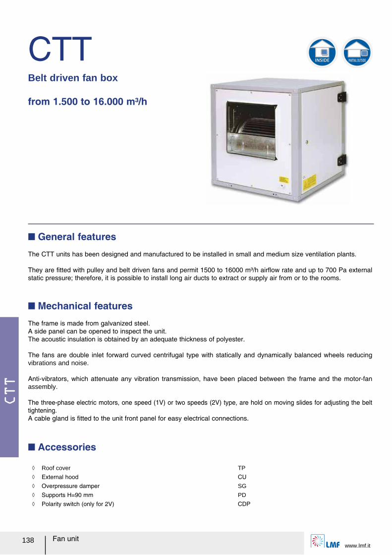
CTT
www.lmf.it138 Fan unit
CTTBelt driven fan box
from 1.500 to 16.000 m³/h
The CTT units has been designed and manufactured to be installed in small and medium size ventilation plants.
They are ルtted with pulley and belt driven fans and permit 1500 to 16000 m³/h airレow rate and up to 700 Pa external static pressure; therefore, it is possible to install long air ducts to extract or supply air from or to the rooms.
Q General features
Q Mechanical features
The frame is made from galvanized steel.A side panel can be opened to inspect the unit.The acoustic insulation is obtained by an adequate thickness of polyester.
The fans are double inlet forward curved centrifugal type with statically and dynamically balanced wheels reducing vibrations and noise.
Anti-vibrators, which attenuate any vibration transmission, have been placed between the frame and the motor-fan assembly.
The three-phase electric motors, one speed (1V) or two speeds (2V) type, are hold on moving slides for adjusting the belt tightening. A cable gland is ルtted to the unit front panel for easy electrical connections.
Q Accessories
INSIDE PARTIAL OUTSIDE
ノ Roof cover TP
ノ External hood CU ノ Overpressure damper SG
ノ Supports H=90 mm PD
ノ Polarity switch (only for 2V) CDP
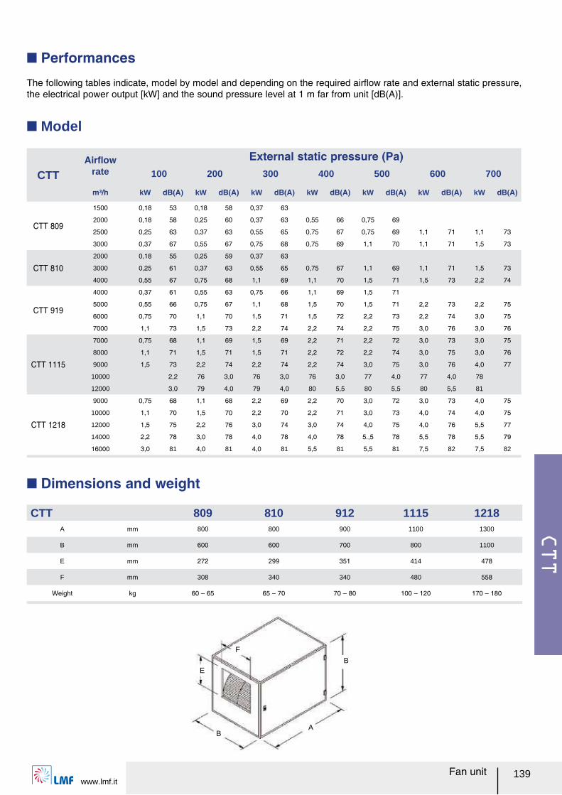
CTT
www.lmf.it139Fan unit
The following tables indicate, model by model and depending on the required airレow rate and external static pressure, the electrical power output [kW] and the sound pressure level at 1 m far from unit [dB(A)].
Q Performances
CTTAirレow
rate
External static pressure (Pa)100 200 300 400 500 600 700
m³/h kW dB(A) kW dB(A) kW dB(A) kW dB(A) kW dB(A) kW dB(A) kW dB(A)
CTT 809
1500 0,18 53 0,18 58 0,37 63
2000 0,18 58 0,25 60 0,37 63 0,55 66 0,75 69
2500 0,25 63 0,37 63 0,55 65 0,75 67 0,75 69 1,1 71 1,1 73
3000 0,37 67 0,55 67 0,75 68 0,75 69 1,1 70 1,1 71 1,5 73
CTT 8102000 0,18 55 0,25 59 0,37 63
3000 0,25 61 0,37 63 0,55 65 0,75 67 1,1 69 1,1 71 1,5 73
4000 0,55 67 0,75 68 1,1 69 1,1 70 1,5 71 1,5 73 2,2 74
CTT 919
4000 0,37 61 0,55 63 0,75 66 1,1 69 1,5 71
5000 0,55 66 0,75 67 1,1 68 1,5 70 1,5 71 2,2 73 2,2 75
6000 0,75 70 1,1 70 1,5 71 1,5 72 2,2 73 2,2 74 3,0 75
7000 1,1 73 1,5 73 2,2 74 2,2 74 2,2 75 3,0 76 3,0 76
CTT 1115
7000 0,75 68 1,1 69 1,5 69 2,2 71 2,2 72 3,0 73 3,0 75
8000 1,1 71 1,5 71 1,5 71 2,2 72 2,2 74 3,0 75 3,0 76
9000 1,5 73 2,2 74 2,2 74 2,2 74 3,0 75 3,0 76 4,0 77
10000 2,2 76 3,0 76 3,0 76 3,0 77 4,0 77 4,0 78
12000 3,0 79 4,0 79 4,0 80 5,5 80 5,5 80 5,5 81
CTT 1218
9000 0,75 68 1,1 68 2,2 69 2,2 70 3,0 72 3,0 73 4,0 75
10000 1,1 70 1,5 70 2,2 70 2,2 71 3,0 73 4,0 74 4,0 75
12000 1,5 75 2,2 76 3,0 74 3,0 74 4,0 75 4,0 76 5,5 77
14000 2,2 78 3,0 78 4,0 78 4,0 78 5.,5 78 5,5 78 5,5 79
16000 3,0 81 4,0 81 4,0 81 5,5 81 5,5 81 7,5 82 7,5 82
Q Model
BA
BE
F
Q Dimensions and weight
CTT 809 810 912 1115 1218A mm 800 800 900 1100 1300
B mm 600 600 700 800 1100
E mm 272 299 351 414 478
F mm 308 340 340 480 558
Weight kg 60 ヲ 65 65 ヲ 70 70 ヲ 80 100 ヲ 120 170 ヲ 180
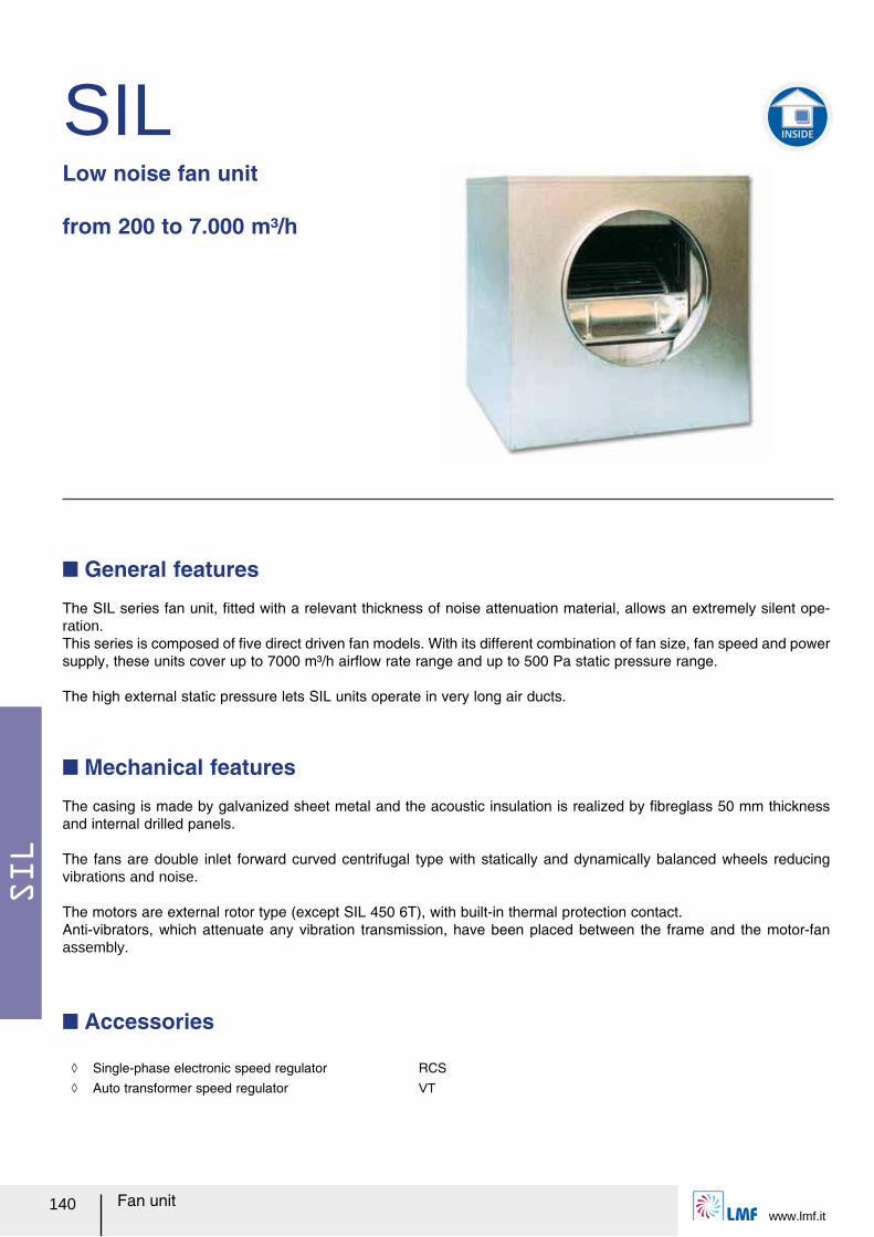
SIL
www.lmf.it140 Fan unit
SILLow noise fan unit
from 200 to 7.000 m³/h
The SIL series fan unit, ルtted with a relevant thickness of noise attenuation material, allows an extremely silent ope-ration. This series is composed of ルve direct driven fan models. With its different combination of fan size, fan speed and power supply, these units cover up to 7000 m³/h airレow rate range and up to 500 Pa static pressure range.
The high external static pressure lets SIL units operate in very long air ducts.
Q General features
Q Mechanical features
The casing is made by galvanized sheet metal and the acoustic insulation is realized by ルbreglass 50 mm thickness and internal drilled panels.
The fans are double inlet forward curved centrifugal type with statically and dynamically balanced wheels reducing vibrations and noise.
The motors are external rotor type (except SIL 450 6T), with built-in thermal protection contact.Anti-vibrators, which attenuate any vibration transmission, have been placed between the frame and the motor-fan assembly.
Q Accessories
INSIDE
ノ Single-phase electronic speed regulator RCS ノ Auto transformer speed regulator VT
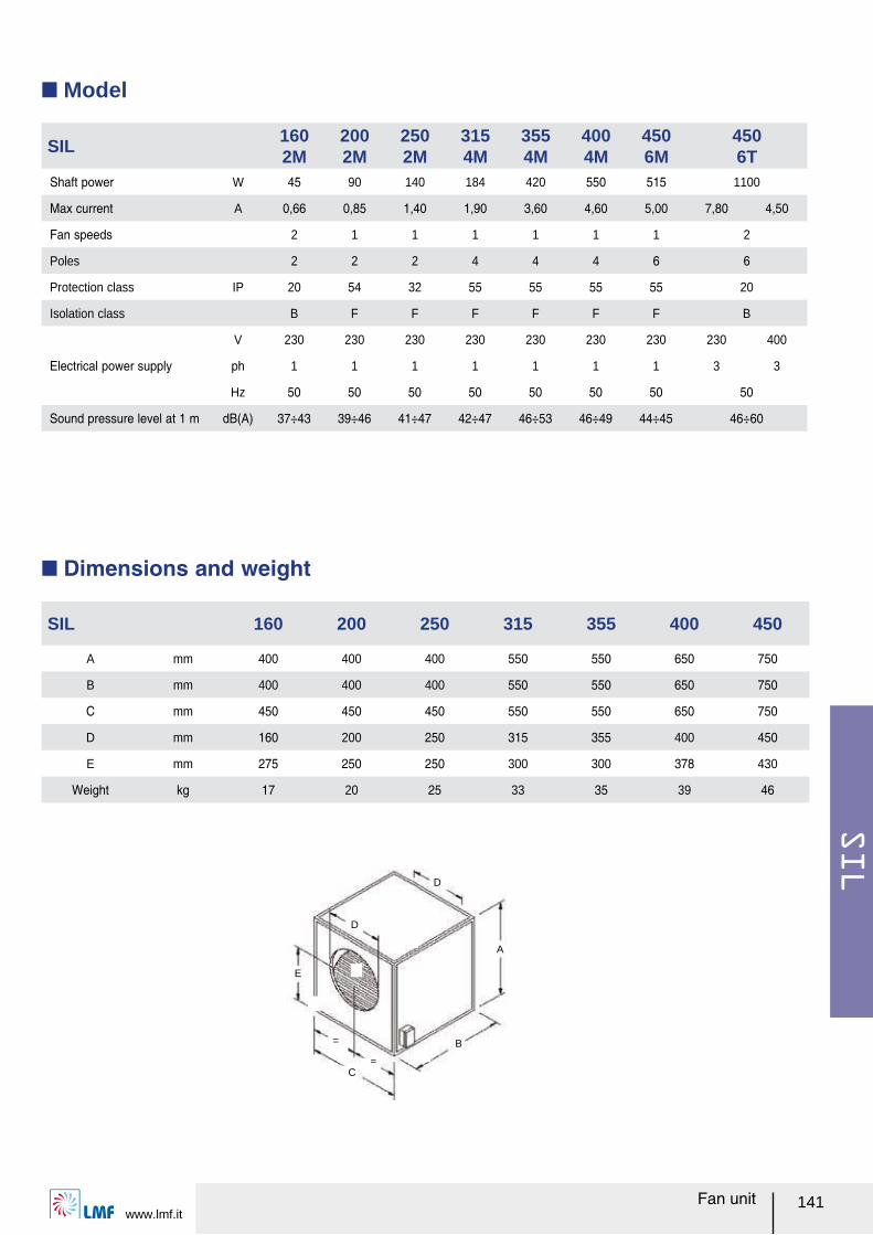
SIL
www.lmf.it141Fan unit
C=
= B
A
E
D
D
Q Model
Q Dimensions and weight
SIL 160 200 250 315 355 400 450
A mm 400 400 400 550 550 650 750
B mm 400 400 400 550 550 650 750
C mm 450 450 450 550 550 650 750
D mm 160 200 250 315 355 400 450
E mm 275 250 250 300 300 378 430
Weight kg 17 20 25 33 35 39 46
SIL160 2M
200 2M
250 2M
315 4M
355 4M
400 4M
450 6M
4506T
Shaft power W 45 90 140 184 420 550 515 1100
Max current A 0,66 0,85 1,40 1,90 3,60 4,60 5,00 7,80 4,50
Fan speeds 2 1 1 1 1 1 1 2
Poles 2 2 2 4 4 4 6 6
Protection class IP 20 54 32 55 55 55 55 20
Isolation class B F F F F F F B
Electrical power supply
V 230 230 230 230 230 230 230 230 400
ph 1 1 1 1 1 1 1 3 3
Hz 50 50 50 50 50 50 50 50
Sound pressure level at 1 m dB(A) 37÷43 39÷46 41÷47 42÷47 46÷53 46÷49 44÷45 46÷60

SIL
www.lmf.it142 Fan unit
The following diagrams indicate, model by model, the external static pressure [Pa] depending on the airレow rate [m³/h].
Q Performances
40030020010000
204060
80100
120140160
180200
37 dB(A) 41 dB(A)
43 dB(A)
SIL
160
2M
120040020000
100
200
600 800 1000
300
400
500
600
41 dB(A)
44 dB(A)
47 dB(A)
SIL
250
2M
200010005000
50
100
1500
150
200
250
300
47 dB(A)
44 dB(A)
43 dB(A)42 dB(A)
SIL
315
4M
70030020010000
50
100
150
250
200
400 500 600
300
350
400
450
39 dB(A)
43 dB(A)
45 dB(A)46 dB(A)
SIL
200
2M
200010005000
50
100
1500
150200
250
450
2500 3000
300
350400
53 dB(A)
47,5 dB(A)
46 dB(A)
SIL
355
4M
20001000500200
250
300
1500
350
400
450
2500 3000
500
550
600
46 dB(A)
47,5 dB(A)
49 dB(A)
SIL
400
4M
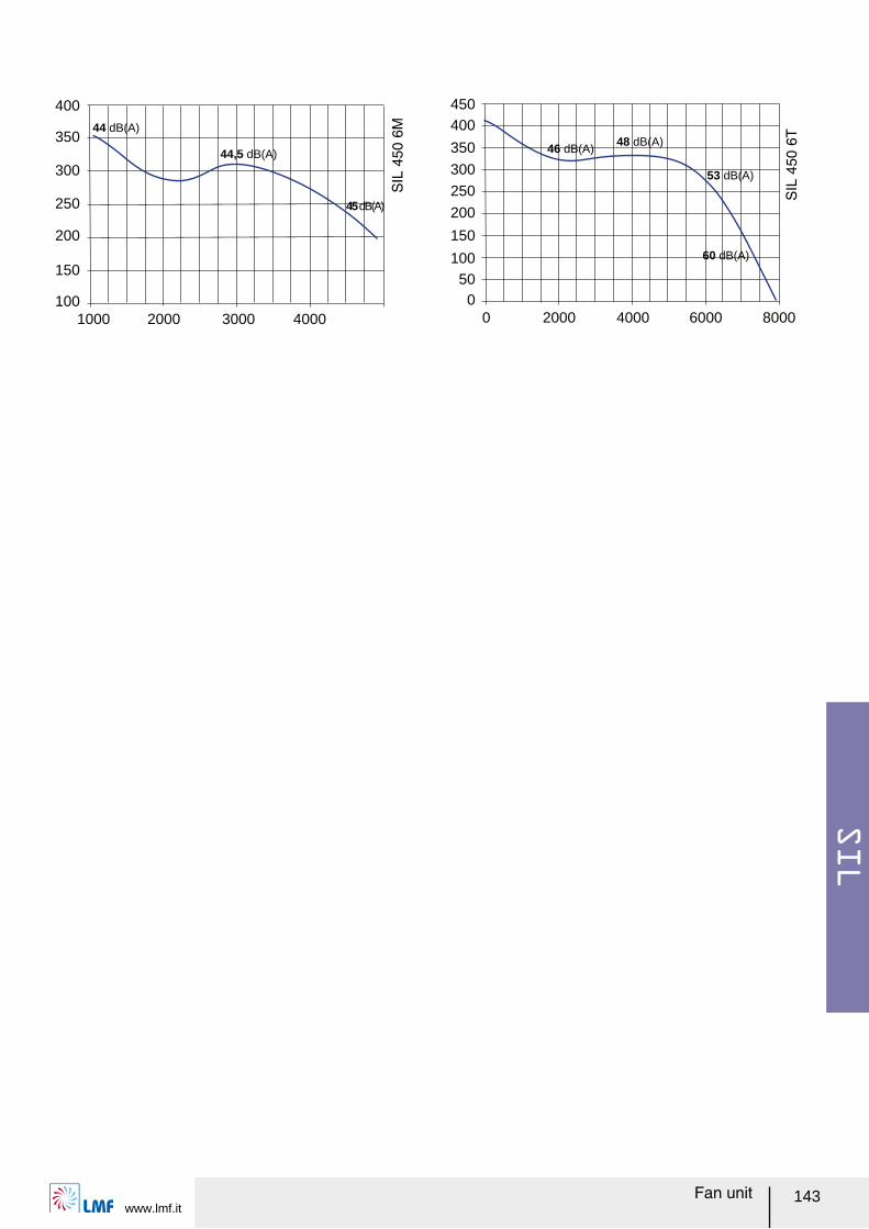
SIL
www.lmf.it143Fan unit
1000100
150
200
2000
300
400
3000 4000
350
250 45 dB(A)
44,5 dB(A)
44 dB(A)
SIL
450
6M
00
50100
2000
300
450
4000
350
150
6000 8000
200
250
400
60 dB(A)
53 dB(A)
48 dB(A)46 dB(A)
SIL
450
6T
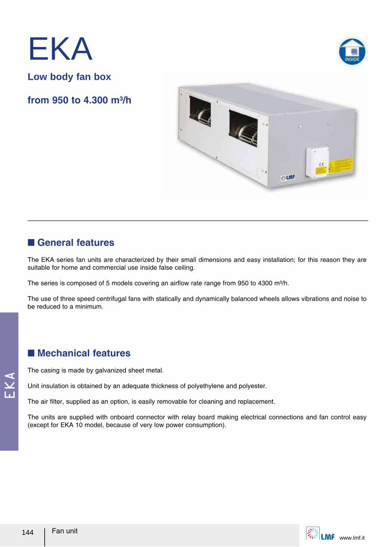
EKA
www.lmf.it144 Fan unit
EKALow body fan box
from 950 to 4.300 m³/h
The EKA series fan units are characterized by their small dimensions and easy installation; for this reason they are suitable for home and commercial use inside false ceiling.
The series is composed of 5 models covering an airレow rate range from 950 to 4300 m³/h.
The use of three speed centrifugal fans with statically and dynamically balanced wheels allows vibrations and noise to be reduced to a minimum.
Q General features
Q Mechanical features
The casing is made by galvanized sheet metal.
Unit insulation is obtained by an adequate thickness of polyethylene and polyester.
The air ルlter, supplied as an option, is easily removable for cleaning and replacement.
The units are supplied with onboard connector with relay board making electrical connections and fan control easy (except for EKA 10 model, because of very low power consumption).
INSIDE
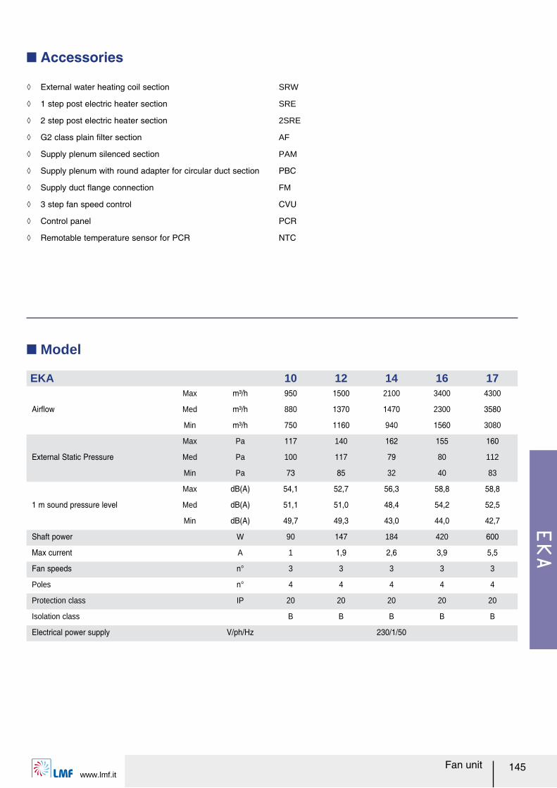
EKA
www.lmf.it145Fan unit
Q Accessories
Q Model
EKA 10 12 14 16 17
Airレow
Max m³/h 950 1500 2100 3400 4300
Med m³/h 880 1370 1470 2300 3580
Min m³/h 750 1160 940 1560 3080
External Static Pressure
Max Pa 117 140 162 155 160
Med Pa 100 117 79 80 112
Min Pa 73 85 32 40 83
1 m sound pressure level
Max dB(A) 54,1 52,7 56,3 58,8 58,8
Med dB(A) 51,1 51,0 48,4 54,2 52,5
Min dB(A) 49,7 49,3 43,0 44,0 42,7
Shaft power W 90 147 184 420 600
Max current A 1 1,9 2,6 3,9 5,5
Fan speeds n° 3 3 3 3 3
Poles n° 4 4 4 4 4
Protection class IP 20 20 20 20 20
Isolation class B B B B B
Electrical power supply V/ph/Hz 230/1/50
ノ External water heating coil section SRW
ノ 1 step post electric heater section SRE
ノ 2 step post electric heater section 2SRE
ノ G2 class plain ルlter section AF
ノ Supply plenum silenced section PAM
ノ Supply plenum with round adapter for circular duct section PBC
ノ Supply duct レange connection FM
ノ 3 step fan speed control CVU
ノ Control panel PCR
ノ Remotable temperature sensor for PCR NTC
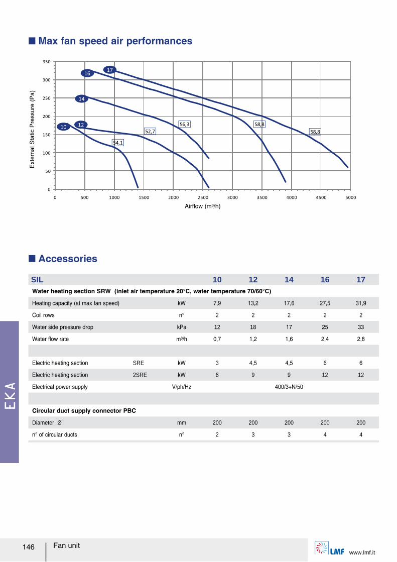
EKA
www.lmf.it146 Fan unit
Q Accessories
SIL 10 12 14 16 17Water heating section SRW (inlet air temperature 20°C, water temperature 70/60°C)
Heating capacity (at max fan speed) kW 7,9 13,2 17,6 27,5 31,9
Coil rows n° 2 2 2 2 2
Water side pressure drop kPa 12 18 17 25 33
Water レow rate m³/h 0,7 1,2 1,6 2,4 2,8
Electric heating section SRE kW 3 4,5 4,5 6 6
Electric heating section 2SRE kW 6 9 9 12 12
Electrical power supply V/ph/Hz 400/3+N/50
Circular duct supply connector PBC
Diameter Ø mm 200 200 200 200 200
n° of circular ducts n° 2 3 3 4 4
Q Max fan speed air performances
0
50
100
150
200
250
300
350
0 500 1000 1500 2000 2500 3000 3500 4000 4500 5000
54,1
52,7
56,3 58,8
58,810 12
14
1617
Airレow (m³/h)
Ext
erna
l Sta
tic P
ress
ure
(Pa)
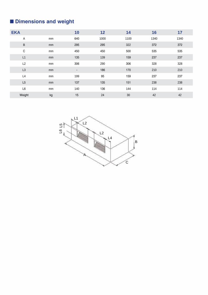
L5L6
A
C
BL4
L2
L2L1
Q Dimensions and weight
EKA 10 12 14 16 17A mm 640 1000 1100 1340 1340
B mm 295 295 322 372 372
C mm 450 450 500 535 535
L1 mm 135 139 159 237 237
L2 mm 306 290 306 328 328
L3 mm - 186 170 210 210
L4 mm 199 95 159 237 237
L5 mm 137 135 151 238 238
L6 mm 140 136 144 114 114
Weight kg 15 24 30 42 42


LMF S.p.A Via Paradiso, 3336040 Meledo di Sarego (VI) - Italy
Tel. +39 0444 821279Fax +39 0444 820323
email: [email protected] www.lmf.it
air and water handling for a comfortable life
www.ferrarogroup.eu